US8162840B2 - High power ultrasound transducer - Google Patents
High power ultrasound transducerDownload PDFInfo
- Publication number
- US8162840B2 US8162840B2US12/199,778US19977808AUS8162840B2US 8162840 B2US8162840 B2US 8162840B2US 19977808 AUS19977808 AUS 19977808AUS 8162840 B2US8162840 B2US 8162840B2
- Authority
- US
- United States
- Prior art keywords
- elements
- impedance matching
- piezoelectric
- matching plate
- high power
- Prior art date
- Legal status (The legal status is an assumption and is not a legal conclusion. Google has not performed a legal analysis and makes no representation as to the accuracy of the status listed.)
- Active, expires
Links
- 238000002604ultrasonographyMethods0.000titleclaimsabstractdescription99
- 239000000919ceramicSubstances0.000claimsabstractdescription69
- 238000000034methodMethods0.000claimsabstractdescription10
- 239000003921oilSubstances0.000claimsdescription32
- 239000011343solid materialSubstances0.000claimsdescription16
- 239000004020conductorSubstances0.000claimsdescription10
- 239000012530fluidSubstances0.000claimsdescription10
- 239000004359castor oilSubstances0.000claimsdescription9
- 235000019438castor oilNutrition0.000claimsdescription9
- ZEMPKEQAKRGZGQ-XOQCFJPHSA-Nglycerol triricinoleateNatural productsCCCCCC[C@@H](O)CC=CCCCCCCCC(=O)OC[C@@H](COC(=O)CCCCCCCC=CC[C@@H](O)CCCCCC)OC(=O)CCCCCCCC=CC[C@H](O)CCCCCCZEMPKEQAKRGZGQ-XOQCFJPHSA-N0.000claimsdescription9
- 238000003825pressingMethods0.000claimsdescription6
- OKTJSMMVPCPJKN-UHFFFAOYSA-NCarbonChemical compound[C]OKTJSMMVPCPJKN-UHFFFAOYSA-N0.000claimsdescription5
- 239000004593EpoxySubstances0.000claimsdescription4
- 229910052751metalInorganic materials0.000claimsdescription4
- 239000002184metalSubstances0.000claimsdescription4
- 239000011347resinSubstances0.000claimsdescription4
- 229920005989resinPolymers0.000claimsdescription4
- 150000001875compoundsChemical class0.000claimsdescription3
- 239000003292glueSubstances0.000claimsdescription3
- 239000002923metal particleSubstances0.000claimsdescription3
- 239000002245particleSubstances0.000claimsdescription3
- 229910000679solderInorganic materials0.000claimsdescription3
- 239000000203mixtureSubstances0.000claimsdescription2
- 239000000463materialSubstances0.000description18
- 210000001519tissueAnatomy0.000description10
- 230000008878couplingEffects0.000description7
- 238000010168coupling processMethods0.000description7
- 238000005859coupling reactionMethods0.000description7
- 230000001225therapeutic effectEffects0.000description7
- 238000007872degassingMethods0.000description4
- 238000005516engineering processMethods0.000description4
- 230000009467reductionEffects0.000description4
- 238000005476solderingMethods0.000description4
- 238000004891communicationMethods0.000description3
- 239000012809cooling fluidSubstances0.000description3
- 229910002804graphiteInorganic materials0.000description3
- 239000010439graphiteSubstances0.000description3
- 229920000642polymerPolymers0.000description3
- 239000007787solidSubstances0.000description3
- RYGMFSIKBFXOCR-UHFFFAOYSA-NCopperChemical compound[Cu]RYGMFSIKBFXOCR-UHFFFAOYSA-N0.000description2
- 238000004026adhesive bondingMethods0.000description2
- 230000000712assemblyEffects0.000description2
- 238000000429assemblyMethods0.000description2
- 230000008901benefitEffects0.000description2
- 238000001816coolingMethods0.000description2
- 229910052802copperInorganic materials0.000description2
- 239000010949copperSubstances0.000description2
- 238000011161developmentMethods0.000description2
- 230000005611electricityEffects0.000description2
- 238000003780insertionMethods0.000description2
- 230000037431insertionEffects0.000description2
- 230000002427irreversible effectEffects0.000description2
- 230000010355oscillationEffects0.000description2
- 229920002635polyurethanePolymers0.000description2
- 239000004814polyurethaneSubstances0.000description2
- 230000008569processEffects0.000description2
- 238000002560therapeutic procedureMethods0.000description2
- 239000011358absorbing materialSubstances0.000description1
- 230000009471actionEffects0.000description1
- 239000000853adhesiveSubstances0.000description1
- 230000001070adhesive effectEffects0.000description1
- 210000000577adipose tissueAnatomy0.000description1
- 229910052782aluminiumInorganic materials0.000description1
- XAGFODPZIPBFFR-UHFFFAOYSA-NaluminiumChemical compound[Al]XAGFODPZIPBFFR-UHFFFAOYSA-N0.000description1
- 230000015572biosynthetic processEffects0.000description1
- 238000004140cleaningMethods0.000description1
- 239000002537cosmeticSubstances0.000description1
- 238000005520cutting processMethods0.000description1
- 230000007547defectEffects0.000description1
- 238000001514detection methodMethods0.000description1
- 238000009826distributionMethods0.000description1
- 230000000694effectsEffects0.000description1
- 230000008030eliminationEffects0.000description1
- 238000003379elimination reactionMethods0.000description1
- 238000002474experimental methodMethods0.000description1
- 238000000605extractionMethods0.000description1
- -1for exampleSubstances0.000description1
- 239000007789gasSubstances0.000description1
- PCHJSUWPFVWCPO-UHFFFAOYSA-NgoldChemical compound[Au]PCHJSUWPFVWCPO-UHFFFAOYSA-N0.000description1
- 229910052737goldInorganic materials0.000description1
- 239000010931goldSubstances0.000description1
- 239000004519greaseSubstances0.000description1
- 230000006872improvementEffects0.000description1
- 230000001939inductive effectEffects0.000description1
- 239000012212insulatorSubstances0.000description1
- 238000004519manufacturing processMethods0.000description1
- 238000002156mixingMethods0.000description1
- 238000012986modificationMethods0.000description1
- 230000004048modificationEffects0.000description1
- 239000012811non-conductive materialSubstances0.000description1
- 244000045947parasiteSpecies0.000description1
- 229920001296polysiloxanePolymers0.000description1
- 238000004382pottingMethods0.000description1
- 230000001902propagating effectEffects0.000description1
- 238000009210therapy by ultrasoundMethods0.000description1
- 238000012546transferMethods0.000description1
- 239000002699waste materialSubstances0.000description1
- XLYOFNOQVPJJNP-UHFFFAOYSA-NwaterSubstancesOXLYOFNOQVPJJNP-UHFFFAOYSA-N0.000description1
- 230000037303wrinklesEffects0.000description1
Images


Classifications
- A—HUMAN NECESSITIES
- A61—MEDICAL OR VETERINARY SCIENCE; HYGIENE
- A61N—ELECTROTHERAPY; MAGNETOTHERAPY; RADIATION THERAPY; ULTRASOUND THERAPY
- A61N7/00—Ultrasound therapy
- A—HUMAN NECESSITIES
- A61—MEDICAL OR VETERINARY SCIENCE; HYGIENE
- A61B—DIAGNOSIS; SURGERY; IDENTIFICATION
- A61B8/00—Diagnosis using ultrasonic, sonic or infrasonic waves
- A—HUMAN NECESSITIES
- A61—MEDICAL OR VETERINARY SCIENCE; HYGIENE
- A61B—DIAGNOSIS; SURGERY; IDENTIFICATION
- A61B8/00—Diagnosis using ultrasonic, sonic or infrasonic waves
- A61B8/54—Control of the diagnostic device
- A61B8/546—Control of the diagnostic device involving monitoring or regulation of device temperature
- B—PERFORMING OPERATIONS; TRANSPORTING
- B06—GENERATING OR TRANSMITTING MECHANICAL VIBRATIONS IN GENERAL
- B06B—METHODS OR APPARATUS FOR GENERATING OR TRANSMITTING MECHANICAL VIBRATIONS OF INFRASONIC, SONIC, OR ULTRASONIC FREQUENCY, e.g. FOR PERFORMING MECHANICAL WORK IN GENERAL
- B06B1/00—Methods or apparatus for generating mechanical vibrations of infrasonic, sonic, or ultrasonic frequency
- B06B1/02—Methods or apparatus for generating mechanical vibrations of infrasonic, sonic, or ultrasonic frequency making use of electrical energy
- B06B1/06—Methods or apparatus for generating mechanical vibrations of infrasonic, sonic, or ultrasonic frequency making use of electrical energy operating with piezoelectric effect or with electrostriction
- B06B1/0607—Methods or apparatus for generating mechanical vibrations of infrasonic, sonic, or ultrasonic frequency making use of electrical energy operating with piezoelectric effect or with electrostriction using multiple elements
- B06B1/0622—Methods or apparatus for generating mechanical vibrations of infrasonic, sonic, or ultrasonic frequency making use of electrical energy operating with piezoelectric effect or with electrostriction using multiple elements on one surface
- B06B1/0629—Square array
- G—PHYSICS
- G01—MEASURING; TESTING
- G01B—MEASURING LENGTH, THICKNESS OR SIMILAR LINEAR DIMENSIONS; MEASURING ANGLES; MEASURING AREAS; MEASURING IRREGULARITIES OF SURFACES OR CONTOURS
- G01B17/00—Measuring arrangements characterised by the use of infrasonic, sonic or ultrasonic vibrations
- G—PHYSICS
- G10—MUSICAL INSTRUMENTS; ACOUSTICS
- G10K—SOUND-PRODUCING DEVICES; METHODS OR DEVICES FOR PROTECTING AGAINST, OR FOR DAMPING, NOISE OR OTHER ACOUSTIC WAVES IN GENERAL; ACOUSTICS NOT OTHERWISE PROVIDED FOR
- G10K11/00—Methods or devices for transmitting, conducting or directing sound in general; Methods or devices for protecting against, or for damping, noise or other acoustic waves in general
- G10K11/02—Mechanical acoustic impedances; Impedance matching, e.g. by horns; Acoustic resonators
- H—ELECTRICITY
- H10—SEMICONDUCTOR DEVICES; ELECTRIC SOLID-STATE DEVICES NOT OTHERWISE PROVIDED FOR
- H10N—ELECTRIC SOLID-STATE DEVICES NOT OTHERWISE PROVIDED FOR
- H10N30/00—Piezoelectric or electrostrictive devices
- H10N30/80—Constructional details
- A—HUMAN NECESSITIES
- A61—MEDICAL OR VETERINARY SCIENCE; HYGIENE
- A61N—ELECTROTHERAPY; MAGNETOTHERAPY; RADIATION THERAPY; ULTRASOUND THERAPY
- A61N7/00—Ultrasound therapy
- A61N2007/0078—Ultrasound therapy with multiple treatment transducers
Definitions
- the present transducergenerally relates to the field of high power ultrasonic transducers and particularly to transducers for high power ultrasonic therapy.
- ultrasound transduceris a device that converts electric energy into ultrasound energy or ultrasound waves. Usually, this term refers to piezoelectric transducers that convert electrical energy into ultrasound. Accordingly, advances in transducer technology play an important role in this technological area.
- Specific characteristics of a high power ultrasound transducerrelate to the ability of providing and sustaining without damage high peak power with high duty cycles; focusing ultrasound and focal spot location control; access to deeper layers of treated tissue, and providing a feedback to control equipment enabling the operator of changing treatment parameters.
- Typical high power transducers used for therapeutic treatmentare composed of piezoelectric material plates, having conducting electrodes on both sides and driven by an alternating voltage (alternating current—AC) electrical power generator.
- the typical operating frequency of these transducersis in the range from 100 kHz to 5 MHz.
- transducer side applied to the treatment locationhas an acoustic impedance matching element to compensate for the large difference between the transducer acoustic impedance and the treated subject acoustic impedance.
- the opposite side of the piezoelectric materialis coupled with either ultrasound reflecting or absorbing material. Efficient use of the energy generated by high power ultrasound transducers is imperative and therefore absorbing backings are not used.
- the absorbing backingis usually replaced by a backing having large acoustic impedance mismatch with the piezoelectric ceramics that reflects most of the ultrasound energy, since such structure reduces ultrasound energy waste.
- the reflecting materialcan be one with acoustic impedance significantly different from that of the piezoelectric material.
- Airis the best reflecting material; however, air cannot be used for high power transducers, where heat removal is a major problem.
- Piezoelectric ceramicmust be provided with a way to remove heat efficiently and air does not possess proper thermal conductivity properties. Oil or solid material with high thermal conductivity are more frequently used for high power ultrasound transducers. The efficient heat removal requirement contradicts some of the solutions used for good ultrasound coupling.
- Phased array transducersare more effective than conventional planar or curved piezoelectric transducers and they are typically used for high power ultrasound treatment applications. Phased array transducers are made by cutting the piezoelectric materials into individual piezoelectric elements—sometimes termed “pixels”, with each pixel having its own-wired connection to an allocated electrical driver. By controlling the phases of each of the electrical drivers, the ultrasound beam could be electronically scanned in the treated location.
- the phased array structurealso has the advantage of reducing parasite oscillations mode compared to a single piece transducer.
- Piezoelectric elements or pixel size and piezoelectric ceramics material thicknessare in the range of a few millimeters. They are attached to the acoustic impedance matching plate with the help of adhesives or soldering, or potting of materials one on the other. The mechanical load caused by the ultrasound vibrations is maximal at the interface of the piezoelectric ceramics with the matching plate. At high peak power, the strength of bonding is not sufficient and the bonding is damaged, so the lifetime of the transducer is short. In case of over-driving the transducer, irreversible damage can occur. Soldering provides a stronger bond than gluing and because of this, instead of the bond, the ceramic piezoelectric material fails.
- Electrodes soldered or glued to the piezoelectric ceramicstend to fail at high power. In some extreme cases, when indeed high ultrasound power is applied the voltage supplying wires may be cut by shear tension. Both direct gluing or soldering of conductive wires to the contacts of the piezoelectric ceramics of flexible printed circuits might fail at high power.
- the high power ultrasound transducerincludes piezoelectric ceramic elements located between an electrically conductive acoustic impedance matching plate and an assembly of electric contacts configured to supply voltage to each of the piezoelectric elements.
- a force generated by one or more resilient conductive elements pressing the piezoelectric ceramic elements against the impedance matching plate and the assembly of electric contacts,enables an electrically conductive path required for voltage supply to the piezoelectric elements.
- FIG. 1is a schematic illustration of a cross section of an exemplary embodiment of the present ultrasound transducer
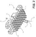
- FIG. 2is a schematic illustration of an exemplary embodiment of a multi section bin for locating and holding piezoelectric ceramic elements
- FIG. 3is a schematic illustration of another cross section of an exemplary embodiment of the present ultrasound transducer
- FIG. 4is a schematic illustration of a top view of the present ultrasound transducer.
- FIGS. 5A and 5Bare schematic illustrations of two exemplary assemblies of the present ultrasound transducer.
- Transducer 100comprises a housing 104 covered by a lid or cover 108 .
- One or more piezoelectric ceramics elements 112 having contacts deposited on the lower and upper sides 120 and 124 of the piezoelectric ceramics elements 112are arranged in a multi section bin 116 , shown in more detail in FIG. 2 , such that each of piezoelectric elements 112 is capable of operating independently and does not interfere with the operation of a neighboring piezoelectric element.
- Bin 116 with the piezoelectric elementsis located in the inner cavity 132 of housing 104 such that one of the contacts of each of piezoelectric elements is in electrical communication with a conductive acoustic impedance matching material plate 128 located in the inner cavity 132 of housing 104 .
- Impedance matching plate 128is a mixture of conductive particles, for example metal particles or graphite powder with a resin.
- Epoxymay be a sample of such resin and in particular, graphite impregnated epoxy or any other conductive material impregnated polymer possessing similar properties such as epoxy. These materials are conductive and enable voltage application to contacts 120 .
- the electrically conductive acoustic impedance matching material plate 128represents a common electrical connection to all of the piezoelectric elements 112 of transducer 100 .
- the matching platecan also be made of a non-conductive material, which is plated by a thin layer of conducting material such as copper or gold.
- An assembly of electric contacts implemented as a rigid or flexible printed wiring board 136 , metal coated ceramics, or any other form of contacts configured to provide voltage to each of piezoelectric elements 112is connected to a source of ultrasound energy 114 .
- Source 114may include one or more ultrasound generators or drivers 118 operative to provide voltage to each of said piezoelectric ceramic elements 112 and a controller 122 that synchronizes operation of ultrasound generators or drivers 118 and accordingly of piezoelectric ceramic elements 112 .
- Resilient, electrically conductive elements 140 inserted in appropriate holes of multi section bin 116are located between second contact 124 of piezoelectric element 112 and protruding or flat pads 130 ( FIG. 4 ) of the assembly of electric contacts implemented as a flexible printed circuit 136 . They enable an electric pass from flexible printed circuit 136 to piezoelectric ceramic elements 112 .
- An interim plate 142is configured to lock and slightly push circuit 136 against resilient elements 140 such that pressure applied by elements 140 is transferred to piezoelectric ceramic 112 ensuring a contact with conductive impedance matching plate 128 .
- Cover 108seals cavity 132 .
- Resilient, electrically conductive elements 140may be such as metal springs or polymeric electrically conductive materials, for example, graphite or metal particles loaded silicone or other similar polymers.
- the force developed by resilient elements 140is affecting each of the piezoelectric ceramic elements 112 by pushing them against conductive impedance matching plate 128 and enabling a reliable electric contact between first end 120 of piezoelectric elements 112 and conductive acoustic impedance matching plate 128 .
- First end of resilient elements 140is in contact with second piezoelectric electrode 124 where the second end of resilient element 140 is in contact with pads 130 of flexible printed circuit 136 .
- the space between themcould be filled with fluid.
- fluidcan be a fluid, a gel or grease.
- Most of non-solid materials with proper acoustic propertiesmay be used as coupling material. It was found that best results are obtained with different oils, and in particular with castor oil.
- the oilfills the miniscule vacancies existing at the interface of the piezoelectric-ceramic 112 and the acoustic impedance matching plate 128 and forms a thin oil layer between piezoelectric elements 112 and impedance matching plate 128 .
- the oilmay fill-in cavity 132 of transducer 100 and the piezoelectric ceramic elements 112 operate being immersed in the oil. This improves heat removal from the piezoelectric elements 112 and also prevents high voltage sparking between the elements.
- the acoustic impedance matching plate 128made as mentioned above from epoxy-impregnated graphite, in addition to being a good electric conductor is also a good heat conductor.
- the heat generated in the course of operation of the piezoelectric ceramic elements 112flows through the impedance matching plate 128 to housing 104 , which is typically made of a good heat conductor such as aluminum or copper, and through housing 104 to a thermoelectric cooler 144 .
- Thermoelectric cooler 144 located on surface 148 of cover 108operates to cool the housing and oil and maintain the desired transducer operating temperature.
- a heat sink 152 with heat distribution fins 156 and cooling fluid supply channels 160cools the hot side of thermoelectric cooler 144 .
- the cooling fluidmay be water or any other fluid suitable for the task.
- the oilincluding castor oil
- resilient electrically conducting elements 136press piezoelectric-ceramic 112 with their contact 120 being in electrical communication with impedance matching plate 128 , the electricity passes between them despite oil presence.
- the contact surfacesare not perfect and as indicated above, have miniscule vacancies and hills in the order of a fraction of a micron.
- the hills on the surface of the piezoelectric-ceramic 112are in direct contact with hills on the surface of acoustic impedance matching plate 128 and the electricity passes through these contacts.
- the overall combination of hills contacting acoustic impedance matching plate 128 and vacancies filled with oilhas relatively low electric resistance.
- the other electrode 124 of piezoelectric element/s 112is in contact with the resilient electrically conductive element 140 pushing piezoelectric-ceramic elements 112 to matching plate 128 .
- the electrical connection enabled by the resilient electrically conductive element 140generates a small, practically negligible acoustical load on the piezoelectric-ceramic 112 , but the high power ultrasound does not damage the voltage (electrical) supply path.
- the electrical connection of the piezoelectric ceramicsdoes not contain wires, soldering or other elements typically damaged by high power ultrasound.
- the acoustic impedance matching material or platemay be coated with a layer of conductive material.
- acoustic impedance matching plate 128In order to use a larger amount of the power generated by a high power ultrasound transducer, it is desired to reflect the portion of ultrasound energy propagating in the direction away from the acoustic impedance matching plate 128 , as it is illustrated by arrow A. Good ultrasound reflection may be achieved at the boundary of materials having large acoustic impedance mismatch. While air or vacuum have large acoustic impedance mismatch with the piezoelectric ceramic, both have poor thermal conductivity.
- the same oil, that fills in cavity 132 and serves as an acoustic impedance matching and transducer cooling fluidhas large mismatch of acoustic impedance with the piezoelectric-ceramics.
- the acoustic impedance of oilis about 1.4MR, much smaller than that of the piezoelectric-ceramic, which is about 33-34MR.
- FIG. 2is a schematic illustration of the multi-section bin 116 for locating and holding piezoelectric ceramic elements 112 .
- Each piezoelectric element 112is inserted into its nest 200 .
- Walls 204separate between the nests and piezoelectric elements 112 such that ultrasound emitted by one of the elements does not affect the neighboring elements.
- bin 116When bin 116 is fastened in place, it locates elements 112 such that contact 120 is enabled to be in electrical communication with acoustic impedance matching plate 128 ( FIG. 1 ).
- Arrow 208illustrates the insertion direction of piezoelectric ceramic elements 112 and arrow 212 the insertion direction of resilient conductive elements 140 shown as a spring.
- FIG. 3is a schematic illustration of an additional cross section of the present ultrasound transducer. It illustrates the location of piezoelectric ceramic elements 112 , multi-section bin 116 , walls 204 defining the nest 200 for each piezoelectric ceramic element 112 and flexible printed circuit 136 .
- impedance matching plate 128is a solid plate.
- impedance matching plate 128is a solid plate having on the side contacting piezoelectric ceramic elements 112 incisions 300 . Incisions 300 serve to reduce acoustical coupling between the elements and surface wave propagation on the matching plate. In this way efficiency, focusing and scanning capabilities of the transducer are improved.
- FIG. 4is a schematic illustration of a top view of the present ultrasound transducer.
- Transducer 100is shown without cover 108 , thermoelectric cooler 144 and other components associated with them.
- Flexible printed circuit 136contains pads 130 , that may protrude over the surface of circuit 136 enabling easier contact with resilient electrically conducting elements 140 .
- Connector 400provides electrical connection between each of piezoelectric ceramic elements 112 and their respective drivers 118 ( FIG. 1 ).
- FIGS. 5A and 5Bare schematic illustrations of two exemplary assemblies of the present ultrasound transducer for therapeutic use.
- the therapiesinclude adipose tissue reduction, skin wrinkles elimination and some other cosmetic and therapeutic applications.
- Transducer 100may be applied to tissue as a component of an ultrasound tissue treatment applicator, such as the one disclosed in U.S. provisional patent application No. 61/081,110 assigned to the same assignee and attached herein for reference purposes only as Appendix A.
- the transducer surface as shown in FIG. 5A that would be in contact with the tissuemay be slanted to match the desired tissue protrusion angle.
- a wedge 504is located between the tissue and the impedance matching plate 128 .
- the wedgeis made from a material having acoustic impedance close to that of the human body to prevent ultrasound reflection. Polyurethane or other suitable polymers may be used.
- transducer 100is adapted to contact a relatively flat portion of the tissue.
- a flat plate 508 made from polyurethane or similaris located between the tissue and the impedance matching plate 128 .
- the high power ultrasound transducer described abovemay be used in a variety of therapeutic medical application.
- the use of the transduceris not limited however, to medical applications only. It may be applied to different fluids mixing processes, different ultrasound cleaning applications, defect detection applications, and other applications that are in need of high ultrasound power.
- the piezoelectric material for the high power transducerwould typically be one of the PZT ceramics families.
- the oscillation frequency of the transduceris between 100 kHz to 5 MHz, or 100 kHz to 1 MHz, or 100 kHz to 400 kHz.
- the peak power at the transducer radiating surfacemay be between 10 W/cm 2 to 500 W/cm 2 , or 50 W/cm 2 to 200 W/cm 2 , and typical drive pulse length would be between 20 microseconds to 1 millisecond.
- Average ultrasound powermay be between 0.1 W/cm 2 to 10 W/cm 2 , or 1 W/cm 2 to 3 W/cm 2 .
- Typical number of piezoelectric ceramic elements in a transducermay be between 4 to 128, or 8 to 64, with the size of each of the elements (pixels) in the array ranging from 1 ⁇ 1 ⁇ 1 mm and up to 6 ⁇ 6 ⁇ 10 mm.
Landscapes
- Health & Medical Sciences (AREA)
- Engineering & Computer Science (AREA)
- Life Sciences & Earth Sciences (AREA)
- Biomedical Technology (AREA)
- Nuclear Medicine, Radiotherapy & Molecular Imaging (AREA)
- Radiology & Medical Imaging (AREA)
- Animal Behavior & Ethology (AREA)
- General Health & Medical Sciences (AREA)
- Public Health (AREA)
- Veterinary Medicine (AREA)
- Physics & Mathematics (AREA)
- Mechanical Engineering (AREA)
- Biophysics (AREA)
- Pathology (AREA)
- Heart & Thoracic Surgery (AREA)
- Medical Informatics (AREA)
- Molecular Biology (AREA)
- Surgery (AREA)
- Acoustics & Sound (AREA)
- Multimedia (AREA)
- General Physics & Mathematics (AREA)
- Transducers For Ultrasonic Waves (AREA)
- Surgical Instruments (AREA)
- Investigating Or Analyzing Materials By The Use Of Ultrasonic Waves (AREA)
Abstract
Description
Claims (35)
Priority Applications (10)
| Application Number | Priority Date | Filing Date | Title |
|---|---|---|---|
| US12/199,778US8162840B2 (en) | 2008-07-16 | 2008-08-27 | High power ultrasound transducer |
| PCT/IL2009/000694WO2010023653A1 (en) | 2008-08-27 | 2009-07-12 | High power ultrasound transducer |
| CN2009801332035ACN102131464A (en) | 2008-08-27 | 2009-07-12 | High power ultrasound transducer |
| AU2009286350AAU2009286350A1 (en) | 2008-08-27 | 2009-07-12 | High power ultrasound transducer |
| BRPI0916393ABRPI0916393A2 (en) | 2008-08-27 | 2009-07-12 | high power ultrasonic transducer |
| EP09809421.2AEP2317928A4 (en) | 2008-08-27 | 2009-07-12 | High power ultrasound transducer |
| KR1020117001598AKR101628411B1 (en) | 2008-08-27 | 2009-07-12 | High power ultrasound transducer |
| MX2011002103AMX2011002103A (en) | 2008-08-27 | 2009-07-12 | High power ultrasound transducer. |
| JP2011524515AJP5484466B2 (en) | 2008-08-27 | 2009-07-12 | High power ultrasonic transducer |
| IL210601AIL210601A (en) | 2008-08-27 | 2011-01-13 | High power ultrasound transducer |
Applications Claiming Priority (2)
| Application Number | Priority Date | Filing Date | Title |
|---|---|---|---|
| US8111008P | 2008-07-16 | 2008-07-16 | |
| US12/199,778US8162840B2 (en) | 2008-07-16 | 2008-08-27 | High power ultrasound transducer |
Publications (2)
| Publication Number | Publication Date |
|---|---|
| US20100016727A1 US20100016727A1 (en) | 2010-01-21 |
| US8162840B2true US8162840B2 (en) | 2012-04-24 |
Family
ID=41722755
Family Applications (1)
| Application Number | Title | Priority Date | Filing Date |
|---|---|---|---|
| US12/199,778Active2031-01-30US8162840B2 (en) | 2008-07-16 | 2008-08-27 | High power ultrasound transducer |
Country Status (10)
| Country | Link |
|---|---|
| US (1) | US8162840B2 (en) |
| EP (1) | EP2317928A4 (en) |
| JP (1) | JP5484466B2 (en) |
| KR (1) | KR101628411B1 (en) |
| CN (1) | CN102131464A (en) |
| AU (1) | AU2009286350A1 (en) |
| BR (1) | BRPI0916393A2 (en) |
| IL (1) | IL210601A (en) |
| MX (1) | MX2011002103A (en) |
| WO (1) | WO2010023653A1 (en) |
Cited By (1)
| Publication number | Priority date | Publication date | Assignee | Title |
|---|---|---|---|---|
| US20210108866A1 (en)* | 2019-10-10 | 2021-04-15 | Sunnybrook Research Institute | Systems and methods for cooling ultrasound transducers and ultrasound transducer arrays |
Families Citing this family (44)
| Publication number | Priority date | Publication date | Assignee | Title |
|---|---|---|---|---|
| US8357150B2 (en) | 2009-07-20 | 2013-01-22 | Syneron Medical Ltd. | Method and apparatus for fractional skin treatment |
| ES2563313T3 (en) | 2010-03-19 | 2016-03-14 | Enraf Nonius B.V. | Ultrasonic application device |
| EP2580922B1 (en) | 2010-06-14 | 2019-03-20 | Turtle Beach Corporation | Improved parametric signal processing and emitter systems and related methods |
| KR20140049550A (en)* | 2011-08-09 | 2014-04-25 | 시네론 뷰티 리미티드 | A method and apparatus for cosmetic skin care |
| CN102562029B (en)* | 2011-12-11 | 2015-09-09 | 贵州航天凯山石油仪器有限公司 | Ultrasonic transducer is avoided to rotate method and the ultrasonic transducer fastening structure of installation |
| US9036831B2 (en) | 2012-01-10 | 2015-05-19 | Turtle Beach Corporation | Amplification system, carrier tracking systems and related methods for use in parametric sound systems |
| US8958580B2 (en) | 2012-04-18 | 2015-02-17 | Turtle Beach Corporation | Parametric transducers and related methods |
| US8934650B1 (en) | 2012-07-03 | 2015-01-13 | Turtle Beach Corporation | Low profile parametric transducers and related methods |
| WO2014061806A1 (en)* | 2012-10-19 | 2014-04-24 | 株式会社東芝 | Ultrasonic diagnostic device and ultrasonic probe |
| US8903104B2 (en) | 2013-04-16 | 2014-12-02 | Turtle Beach Corporation | Video gaming system with ultrasonic speakers |
| GB2513884B (en) | 2013-05-08 | 2015-06-17 | Univ Bristol | Method and apparatus for producing an acoustic field |
| US9332344B2 (en) | 2013-06-13 | 2016-05-03 | Turtle Beach Corporation | Self-bias emitter circuit |
| US8988911B2 (en) | 2013-06-13 | 2015-03-24 | Turtle Beach Corporation | Self-bias emitter circuit |
| EP2992829B1 (en)* | 2014-09-02 | 2018-06-20 | Esaote S.p.A. | Ultrasound probe with optimized thermal management |
| GB2530036A (en) | 2014-09-09 | 2016-03-16 | Ultrahaptics Ltd | Method and apparatus for modulating haptic feedback |
| CN107534810B (en) | 2015-02-20 | 2019-12-20 | 超级触觉资讯处理有限公司 | Method for providing improved haptic feedback |
| CA2976312C (en) | 2015-02-20 | 2023-06-13 | Ultrahaptics Ip Limited | Perceptions in a haptic system |
| WO2016137022A1 (en)* | 2015-02-24 | 2016-09-01 | 알피니언메디칼시스템 주식회사 | Ultrasonic transducer comprising matching layer having metal layer and method for manufacturing same |
| US10888084B2 (en) | 2015-07-15 | 2021-01-12 | Nrg Systems, Inc. | Ultrasonic bat deterrent system |
| US10818162B2 (en) | 2015-07-16 | 2020-10-27 | Ultrahaptics Ip Ltd | Calibration techniques in haptic systems |
| CN105149283A (en)* | 2015-09-25 | 2015-12-16 | 无锡市博阳超声电器有限公司 | Ultrasonic cleaning machine high in cooling speed |
| CN108348158B (en) | 2015-11-03 | 2022-02-08 | Nrg系统股份有限公司 | Broadband ultrasonic transducer device for deterrence of wildlife and method of use thereof |
| DE102016101154B4 (en)* | 2016-01-22 | 2024-03-14 | Krohne Ag | Ultrasonic transducer |
| US10268275B2 (en) | 2016-08-03 | 2019-04-23 | Ultrahaptics Ip Ltd | Three-dimensional perceptions in haptic systems |
| WO2018091317A1 (en)* | 2016-11-15 | 2018-05-24 | Koninklijke Philips N.V. | Ultrasound device contacting |
| US10943578B2 (en) | 2016-12-13 | 2021-03-09 | Ultrahaptics Ip Ltd | Driving techniques for phased-array systems |
| US11531395B2 (en) | 2017-11-26 | 2022-12-20 | Ultrahaptics Ip Ltd | Haptic effects from focused acoustic fields |
| EP3729417B1 (en) | 2017-12-22 | 2025-09-10 | Ultrahaptics Ip Ltd | Tracking in haptic systems |
| EP3729418B1 (en) | 2017-12-22 | 2024-11-20 | Ultrahaptics Ip Ltd | Minimizing unwanted responses in haptic systems |
| CN108519440B (en)* | 2018-04-09 | 2024-07-26 | 河北珠峰仪器仪表设备有限公司 | Ultrasonic measurement probe suitable for online detection at high temperature |
| WO2019199978A1 (en)* | 2018-04-10 | 2019-10-17 | Nrg Systems, Inc. | Techniques for providing acoustic impedance matching for a broad-band ultrasonic transducer device and a method of wildlife deterrence using same |
| CA3098642C (en) | 2018-05-02 | 2022-04-19 | Ultrahaptics Ip Ltd | Blocking plate structure for improved acoustic transmission efficiency |
| US11098951B2 (en) | 2018-09-09 | 2021-08-24 | Ultrahaptics Ip Ltd | Ultrasonic-assisted liquid manipulation |
| US20200138512A1 (en)* | 2018-11-06 | 2020-05-07 | Biosense Webster (Israel) Ltd. | Attaining Higher Impedances for Large Indifferent Electrodes |
| EP3906462B1 (en) | 2019-01-04 | 2025-06-18 | Ultrahaptics IP Ltd | Mid-air haptic textures |
| US12373033B2 (en) | 2019-01-04 | 2025-07-29 | Ultrahaptics Ip Ltd | Mid-air haptic textures |
| US11842517B2 (en) | 2019-04-12 | 2023-12-12 | Ultrahaptics Ip Ltd | Using iterative 3D-model fitting for domain adaptation of a hand-pose-estimation neural network |
| US11553295B2 (en) | 2019-10-13 | 2023-01-10 | Ultraleap Limited | Dynamic capping with virtual microphones |
| US11374586B2 (en) | 2019-10-13 | 2022-06-28 | Ultraleap Limited | Reducing harmonic distortion by dithering |
| US11715453B2 (en) | 2019-12-25 | 2023-08-01 | Ultraleap Limited | Acoustic transducer structures |
| CN111110280A (en)* | 2020-01-14 | 2020-05-08 | 浙江艾特超声科技有限公司 | Ultrasonic diagnosis and treatment system |
| US11816267B2 (en) | 2020-06-23 | 2023-11-14 | Ultraleap Limited | Features of airborne ultrasonic fields |
| US11886639B2 (en) | 2020-09-17 | 2024-01-30 | Ultraleap Limited | Ultrahapticons |
| US20220393095A1 (en)* | 2021-06-02 | 2022-12-08 | Ultraleap Limited | Electromechanical Transducer Mount |
Citations (4)
| Publication number | Priority date | Publication date | Assignee | Title |
|---|---|---|---|---|
| US5353798A (en)* | 1991-03-13 | 1994-10-11 | Scimed Life Systems, Incorporated | Intravascular imaging apparatus and methods for use and manufacture |
| US6436051B1 (en)* | 2001-07-20 | 2002-08-20 | Ge Medical Systems Global Technology Company, Llc | Electrical connection system for ultrasonic receiver array |
| US20050075573A1 (en)* | 2002-06-27 | 2005-04-07 | Park William J. | System and method for actively cooling transducer assembly electronics |
| US20080125658A1 (en)* | 2006-09-01 | 2008-05-29 | General Electric Company | Low-profile acoustic transducer assembly |
Family Cites Families (6)
| Publication number | Priority date | Publication date | Assignee | Title |
|---|---|---|---|---|
| DE899574C (en)* | 1941-08-16 | 1953-12-14 | Siemens Ag | Piezoelectric vibration generator |
| US2728869A (en)* | 1950-01-06 | 1955-12-27 | Ultraschall A G | Piezoelectric oscillator or vibrator for ultrasonic waves, especially as an instrument for therapeutical treatment and diagnosis |
| DE1084501B (en)* | 1955-02-10 | 1960-06-30 | Siemens Ag | Sonication head for ultrasound treatment |
| JPS5234763A (en)* | 1975-09-12 | 1977-03-16 | Oki Electric Ind Co Ltd | Process for the fabrication of a compound type device for transmitting and re ceiving waves |
| JPS61161623U (en)* | 1985-03-27 | 1986-10-07 | ||
| JP2000139904A (en)* | 1998-11-06 | 2000-05-23 | Kentsu Medico Kk | Acoustic sensor and electronic stethoscope with it |
- 2008
- 2008-08-27USUS12/199,778patent/US8162840B2/enactiveActive
- 2009
- 2009-07-12MXMX2011002103Apatent/MX2011002103A/ennot_activeApplication Discontinuation
- 2009-07-12AUAU2009286350Apatent/AU2009286350A1/ennot_activeAbandoned
- 2009-07-12KRKR1020117001598Apatent/KR101628411B1/ennot_activeExpired - Fee Related
- 2009-07-12CNCN2009801332035Apatent/CN102131464A/enactivePending
- 2009-07-12EPEP09809421.2Apatent/EP2317928A4/ennot_activeWithdrawn
- 2009-07-12JPJP2011524515Apatent/JP5484466B2/ennot_activeExpired - Fee Related
- 2009-07-12WOPCT/IL2009/000694patent/WO2010023653A1/enactiveApplication Filing
- 2009-07-12BRBRPI0916393Apatent/BRPI0916393A2/ennot_activeIP Right Cessation
- 2011
- 2011-01-13ILIL210601Apatent/IL210601A/ennot_activeIP Right Cessation
Patent Citations (4)
| Publication number | Priority date | Publication date | Assignee | Title |
|---|---|---|---|---|
| US5353798A (en)* | 1991-03-13 | 1994-10-11 | Scimed Life Systems, Incorporated | Intravascular imaging apparatus and methods for use and manufacture |
| US6436051B1 (en)* | 2001-07-20 | 2002-08-20 | Ge Medical Systems Global Technology Company, Llc | Electrical connection system for ultrasonic receiver array |
| US20050075573A1 (en)* | 2002-06-27 | 2005-04-07 | Park William J. | System and method for actively cooling transducer assembly electronics |
| US20080125658A1 (en)* | 2006-09-01 | 2008-05-29 | General Electric Company | Low-profile acoustic transducer assembly |
Cited By (2)
| Publication number | Priority date | Publication date | Assignee | Title |
|---|---|---|---|---|
| US20210108866A1 (en)* | 2019-10-10 | 2021-04-15 | Sunnybrook Research Institute | Systems and methods for cooling ultrasound transducers and ultrasound transducer arrays |
| US11959707B2 (en)* | 2019-10-10 | 2024-04-16 | Sunnybrook Research Institute | Systems and methods for cooling ultrasound transducers and ultrasound transducer arrays |
Also Published As
| Publication number | Publication date |
|---|---|
| IL210601A (en) | 2014-01-30 |
| KR101628411B1 (en) | 2016-06-08 |
| MX2011002103A (en) | 2011-04-07 |
| BRPI0916393A2 (en) | 2016-02-16 |
| EP2317928A1 (en) | 2011-05-11 |
| EP2317928A4 (en) | 2015-04-08 |
| KR20110047187A (en) | 2011-05-06 |
| IL210601A0 (en) | 2011-03-31 |
| JP5484466B2 (en) | 2014-05-07 |
| JP2012511938A (en) | 2012-05-31 |
| CN102131464A (en) | 2011-07-20 |
| US20100016727A1 (en) | 2010-01-21 |
| AU2009286350A1 (en) | 2010-03-04 |
| WO2010023653A1 (en) | 2010-03-04 |
Similar Documents
| Publication | Publication Date | Title |
|---|---|---|
| US8162840B2 (en) | High power ultrasound transducer | |
| US7902728B2 (en) | Thermally enhanced piezoelectric element | |
| US8446071B2 (en) | Thermally enhanced ultrasound transducer system | |
| JP4843395B2 (en) | Ultrasonic probe | |
| CN104010740B (en) | Backing components, ultrasound probe and ultrasonograph display device | |
| CN114555247B (en) | System and method for cooling ultrasound transducers and ultrasound transducer arrays | |
| CN104755032B (en) | Ultrasonic probe | |
| US7378779B2 (en) | Thermally enhanced piezoelectric composite system and method | |
| US20190282207A1 (en) | High intensity focused ultrasound (hifu) device and system | |
| JP2001104356A (en) | Ultrasound therapy equipment | |
| US20250256131A1 (en) | Ultrasound-focusing transducer used in high intensity focused ultrasound device for multifocal treatment, and device comprising same | |
| RU2379125C2 (en) | Ultrasonic transducer, and leather treatment device using it | |
| JP2023502230A (en) | Ultrasonic transducer, backing structure and related method | |
| US8237335B2 (en) | Thermally enhanced ultrasound transducer means | |
| JP2005347804A (en) | Ultrasonic probe | |
| US20070055182A1 (en) | Thermally enhanced ultrasound transducer method | |
| CN221951633U (en) | A piezoelectric ceramic vibrator | |
| US20210121159A1 (en) | Ultrasound probe with improved thermal management | |
| KR20220165421A (en) | Array-type ultrasonic oscillation probe | |
| JP3494578B2 (en) | Ultrasonic probe and manufacturing method thereof | |
| JP2001518386A (en) | Equipment for the generation of ultrasonic sound fields | |
| US20180042580A1 (en) | Ultrasonic probe | |
| JPH06319746A (en) | Ultrasonic therapeutic apparatus | |
| JP5605567B2 (en) | Array type ultrasonic transmitter | |
| KR101651878B1 (en) | Portable skin care apparatus with color therapy function |
Legal Events
| Date | Code | Title | Description |
|---|---|---|---|
| AS | Assignment | Owner name:SYNERON MEDICAL LTD.,ISRAEL Free format text:ASSIGNMENT OF ASSIGNORS INTEREST;ASSIGNOR:ROSENBERG, AVNER;REEL/FRAME:021844/0486 Effective date:20081022 Owner name:SYNERON MEDICAL LTD., ISRAEL Free format text:ASSIGNMENT OF ASSIGNORS INTEREST;ASSIGNOR:ROSENBERG, AVNER;REEL/FRAME:021844/0486 Effective date:20081022 | |
| STCF | Information on status: patent grant | Free format text:PATENTED CASE | |
| FEPP | Fee payment procedure | Free format text:PAYOR NUMBER ASSIGNED (ORIGINAL EVENT CODE: ASPN); ENTITY STATUS OF PATENT OWNER: LARGE ENTITY | |
| FEPP | Fee payment procedure | Free format text:PAT HOLDER NO LONGER CLAIMS SMALL ENTITY STATUS, ENTITY STATUS SET TO UNDISCOUNTED (ORIGINAL EVENT CODE: STOL); ENTITY STATUS OF PATENT OWNER: LARGE ENTITY | |
| FPAY | Fee payment | Year of fee payment:4 | |
| AS | Assignment | Owner name:ING CAPITAL LLC, AS COLLATERAL AGENT, NEW YORK Free format text:SECURITY AGREEMENT;ASSIGNORS:SYNERON MEDICAL LTD.;CANDELA CORPORATION;PRIMAEVA CORPORATION;REEL/FRAME:043925/0001 Effective date:20170920 | |
| MAFP | Maintenance fee payment | Free format text:PAYMENT OF MAINTENANCE FEE, 8TH YEAR, LARGE ENTITY (ORIGINAL EVENT CODE: M1552); ENTITY STATUS OF PATENT OWNER: LARGE ENTITY Year of fee payment:8 | |
| AS | Assignment | Owner name:PRIMAEVA CORPORATION, MASSACHUSETTS Free format text:RELEASE (REEL 043925 / FRAME 0001);ASSIGNOR:ING CAPITAL LLC;REEL/FRAME:059593/0131 Effective date:20220401 Owner name:CANDELA CORPORATION, MASSACHUSETTS Free format text:RELEASE (REEL 043925 / FRAME 0001);ASSIGNOR:ING CAPITAL LLC;REEL/FRAME:059593/0131 Effective date:20220401 Owner name:SYNERON MEDICAL LTD., ISRAEL Free format text:RELEASE (REEL 043925 / FRAME 0001);ASSIGNOR:ING CAPITAL LLC;REEL/FRAME:059593/0131 Effective date:20220401 Owner name:BARCLAYS BANK PLC, AS COLLATERAL AGENT, NEW YORK Free format text:SECURITY AGREEMENT;ASSIGNORS:CANDELA CORPORATION;SYNERON MEDICAL LTD.;REEL/FRAME:059593/0269 Effective date:20220401 | |
| MAFP | Maintenance fee payment | Free format text:PAYMENT OF MAINTENANCE FEE, 12TH YEAR, LARGE ENTITY (ORIGINAL EVENT CODE: M1553); ENTITY STATUS OF PATENT OWNER: LARGE ENTITY Year of fee payment:12 |