US8162516B2 - LED reading lamp - Google Patents
LED reading lampDownload PDFInfo
- Publication number
- US8162516B2 US8162516B2US12/477,114US47711409AUS8162516B2US 8162516 B2US8162516 B2US 8162516B2US 47711409 AUS47711409 AUS 47711409AUS 8162516 B2US8162516 B2US 8162516B2
- Authority
- US
- United States
- Prior art keywords
- supporting bracket
- heat sink
- horizontal part
- opening
- lamp
- Prior art date
- Legal status (The legal status is an assumption and is not a legal conclusion. Google has not performed a legal analysis and makes no representation as to the accuracy of the status listed.)
- Expired - Fee Related, expires
Links
- 238000005452bendingMethods0.000claimsdescription3
- 239000012780transparent materialSubstances0.000claimsdescription3
- 238000010438heat treatmentMethods0.000description2
- WABPQHHGFIMREM-UHFFFAOYSA-Nlead(0)Chemical compound[Pb]WABPQHHGFIMREM-UHFFFAOYSA-N0.000description2
- 230000002411adverseEffects0.000description1
- 230000020169heat generationEffects0.000description1
- 238000005286illuminationMethods0.000description1
- 239000007769metal materialSubstances0.000description1
Images


Classifications
- F—MECHANICAL ENGINEERING; LIGHTING; HEATING; WEAPONS; BLASTING
- F21—LIGHTING
- F21S—NON-PORTABLE LIGHTING DEVICES; SYSTEMS THEREOF; VEHICLE LIGHTING DEVICES SPECIALLY ADAPTED FOR VEHICLE EXTERIORS
- F21S6/00—Lighting devices intended to be free-standing
- F21S6/002—Table lamps, e.g. for ambient lighting
- F21S6/003—Table lamps, e.g. for ambient lighting for task lighting, e.g. for reading or desk work, e.g. angle poise lamps
- F—MECHANICAL ENGINEERING; LIGHTING; HEATING; WEAPONS; BLASTING
- F21—LIGHTING
- F21Y—INDEXING SCHEME ASSOCIATED WITH SUBCLASSES F21K, F21L, F21S and F21V, RELATING TO THE FORM OR THE KIND OF THE LIGHT SOURCES OR OF THE COLOUR OF THE LIGHT EMITTED
- F21Y2115/00—Light-generating elements of semiconductor light sources
- F21Y2115/10—Light-emitting diodes [LED]
Definitions
- the present disclosurerelates to a reading lamp and, more particularly, to a LED (light emitting diode) reading lamp which utilizes an LED module as a light source.
- incandescent and fluorescent lightsare quite inefficient.
- An incandescent and fluorescent lightconverts a large amount of energy to heat rather than light, and fluorescent lamps have a relative high start up power consumption. Accordingly, new ways to provide more efficient lighting use are desired in reading lamp.
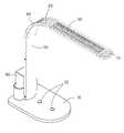
- FIG. 1is an assembled, isometric view of an LED reading lamp in accordance with an embodiment of the present disclosure.
- FIG. 2is an exploded view of the LED reading lamp of FIG. 1 .
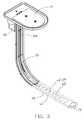
- FIG. 3is an inverted view of the LED reading lamp of FIG. 1 , with a cover taken away.
- the LED reading lampadapted for being placed on a desk to provide comfortable light for reading is illustrated.
- the LED reading lampcomprises a base 10 , a supporting bracket 20 fixed on a top of the base 10 , a heat sink 30 mounted on the supporting bracket 20 , an LED module 40 attached to a bottom surface of the heat sink 30 , a lamp cover 50 mounted to an inner face of the supporting bracket 20 , two clipping members 60 clipping the lamp cover 50 and the supporting bracket 20 together, and an end cap 70 mounted to an upper free end of the supporting bracket 20 .
- the base 10is provided with two switches 12 thereon to turn on/off the LED reading lamp and defines a plurality of mounting holes 14 therein for allowing screws 100 extending upwardly therethrough to engage with the supporting bracket 20 .
- the supporting bracket 20is formed by bending an elongated plastic or metallic plate and substantially L-shaped.
- the supporting bracket 20comprises a vertical part 22 vertically standing on the base 10 and a horizontal part 24 bent from an upper end of the vertical part 22 and parallel to the base 10 .
- a round corneris formed at a joint of the vertical part 22 and the horizontal part 24 .
- a plurality of spaced protruding strips 26are arranged on an outer surface of the supporting bracket 20 along a lengthwise direction of the supporting bracket 20 and parallel to two opposite lateral sides of the supporting bracket 20 .
- the horizontal part 24defines an elongated opening 242 in a central portion along the lengthwise direction thereof.
- a rectangular, annular and flat supporting part 244is formed on a top surface of the horizontal part 24 and surrounds the opening 242 .
- a plurality of fixing holes 28are defined in the two opposite lateral sides of the supporting bracket 20 for engagingly receiving screws (not shown) extending through the clipping members 60 to couple the two clipping members 60 to the lateral sides of the supporting bracket 20 .
- the heat sink 30comprises a base plate 32 and a plurality of spaced fins 34 extending upwardly from a top surface of the base plate 32 .
- the base plate 32is constructed to perfectly match the supporting part 244 of the supporting bracket 20 .
- the fins 34 parallel to each otherare arranged in a direction consistent to that of the protruding strips 26 of the supporting bracket 20 and have top ends coplanar with top ends of the protruding strips 26 of the horizontal part 24 of the bracket 20 .
- a central part of a bottom surface of the base plate 32is corresponding to the opening 242 of the horizontal part 24 and exposed to the opening 242 .
- the LED module 40is accommodated in the opening 242 of the supporting bracket 20 and attached to the central part of the bottom surface of the base plate 32 of the heat sink 30 .
- the LED module 40comprises an elongated printed circuit board 42 having one side engaging with the central part of the bottom surface of the base plate 32 and a plurality of LED components 44 mounted on another side of the printed circuit board 42 and facing downwards.
- the lamp cover 50is made of semi-transparent or transparent material and bent into an L-shape to match and cover the inner face of the supporting bracket 20 .
- the lamp cover 50has two flatted engaging flanges 52 formed at two lateral portions thereof.
- the two engaging flanges 52are intimately attached to two corresponding lateral portions of the inner face of the supporting bracket 20 .
- a middle portion of the lamp cover 50 connected to two facing inner edges of the two engaging flanges 52plumps up to form a covering space between the lamp cover 50 and the supporting bracket 20 .
- the clipping members 60are fixed to opposite lateral sides of the supporting bracket 20 and the lamp cover 50 .
- Each clipping member 60comprises a connecting strip 62 and two clipping flanges 64 extending perpendicularly from two opposite long edges of the connecting strip 62 .
- the connecting strip 62is L-shaped and fitly attached to the lateral sides of the supporting bracket 20 and the lamp cover 50 at a same side.
- the connecting strip 62defines a plurality of through holes 65 therein for the screws extending therethrough and being screwed into the corresponding fixing holes 28 in the lateral side of the supporting bracket 20 to fix the clipping member 60 at the lateral sides of the supporting bracket 20 and the lamp cover 50 .
- the clipping flanges 62 of each clipping member 60sandwich the corresponding lateral portions of the supporting bracket 20 and the engaging flange 52 of the lamp cover 50 therebetween to securely clip the supporting bracket 20 and the lamp cover 50 together.
- the end cap 70is connected to the free ends of the supporting bracket 20 and the lamp cover 50 and has a plurality of protruding strips (not labeled) formed on a top surface thereof and joining the protruding strips 26 of the supporting bracket 20 .
- the LED reading lampfurther includes an accessional member 80 placed on the base 10 and located at an outer side of the vertical part 22 of the supporting bracket 20 .
- the accessional member 80comprises a receiving box 82 for receiving related electronic components such as driving and controlling circuit boards, etc. and two semi-cylindrical pencil vases 84 formed at two opposite lateral sides of the receiving box 82 .
- a lead wire 200extends along the inner face of the supporting bracket 20 to electrically connect the related electronic components in the receiving box 82 and the LED module 40 .
- the LED module 40In use, light generated by the LED module 40 passes through the lamp cover 50 to provide readers with comfortable illumination for reading. Heat generated by the LED module 40 is directly adsorbed by the base plate 32 of the heat sink 30 and then distributed over the fins 34 of the heat sink 30 to dissipate into ambient environment.
- the supporting bracket 20can be made of metallic material and also can be in thermal conducting relationship with the base plate 32 of the heat sink 30 , the heat accumulated in the base plate 32 also can be simultaneously conducted to the protruding strips 26 formed on the outer face of the supporting bracket 20 to dissipate into ambient environment.
- the lifespan of the LED components 44 of the LED module 40has at least 100,000 working hours; therefore, the LED reading lamp can provide a relatively longer usage than the conventional reading lamp using bulb or fluorescent light.
Landscapes
- Engineering & Computer Science (AREA)
- General Engineering & Computer Science (AREA)
- Arrangement Of Elements, Cooling, Sealing, Or The Like Of Lighting Devices (AREA)
- Non-Portable Lighting Devices Or Systems Thereof (AREA)
Abstract
Description
Claims (19)
Applications Claiming Priority (3)
| Application Number | Priority Date | Filing Date | Title |
|---|---|---|---|
| CN2008103065661ACN101769471B (en) | 2008-12-26 | 2008-12-26 | Light-emitting diode table lamp |
| CN200810306566.1 | 2008-12-26 | ||
| CN200810306566 | 2008-12-26 |
Publications (2)
| Publication Number | Publication Date |
|---|---|
| US20100165644A1 US20100165644A1 (en) | 2010-07-01 |
| US8162516B2true US8162516B2 (en) | 2012-04-24 |
Family
ID=42284730
Family Applications (1)
| Application Number | Title | Priority Date | Filing Date |
|---|---|---|---|
| US12/477,114Expired - Fee RelatedUS8162516B2 (en) | 2008-12-26 | 2009-06-02 | LED reading lamp |
Country Status (2)
| Country | Link |
|---|---|
| US (1) | US8162516B2 (en) |
| CN (1) | CN101769471B (en) |
Cited By (3)
| Publication number | Priority date | Publication date | Assignee | Title |
|---|---|---|---|---|
| USD696806S1 (en)* | 2012-07-27 | 2013-12-31 | Koninklijke Philips N.V. | Luminaire for road lighting |
| USD696807S1 (en)* | 2012-07-27 | 2013-12-31 | Koninklijke Philips N.V. | Luminaire for road lighting |
| USD744154S1 (en)* | 2014-03-14 | 2015-11-24 | Koncept, Inc. | Lamp |
Families Citing this family (4)
| Publication number | Priority date | Publication date | Assignee | Title |
|---|---|---|---|---|
| CN101769471B (en)* | 2008-12-26 | 2012-11-21 | 富准精密工业(深圳)有限公司 | Light-emitting diode table lamp |
| US10539278B2 (en)* | 2014-08-31 | 2020-01-21 | Abl Ip Holding, Llc | Luminaire for creating effective proximity lighting in a low ambient lighting environment |
| USD1001347S1 (en)* | 2019-10-16 | 2023-10-10 | Dong Guan Jia Sheng Lighting Technology Co., Ltd. China | Magnetically levitation acoustics lamp |
| JP1722171S (en)* | 2021-11-05 | 2022-08-10 | table lamp |
Citations (7)
| Publication number | Priority date | Publication date | Assignee | Title |
|---|---|---|---|---|
| US4654762A (en)* | 1985-04-01 | 1987-03-31 | Wizer Equipment, Inc. | Light table |
| CN101109498A (en) | 2007-08-11 | 2008-01-23 | 石明峰 | Desk lamp |
| US20080062687A1 (en)* | 2006-05-09 | 2008-03-13 | Herman Miller, Inc. | Lamp |
| CN201041338Y (en) | 2007-06-06 | 2008-03-26 | 奥古斯丁科技股份有限公司 | Light emitting diode lighting device |
| CN201057395Y (en) | 2007-05-29 | 2008-05-07 | 福建嘉能光电科技有限公司 | LED industrial desk lamp |
| US20090180284A1 (en)* | 2008-01-10 | 2009-07-16 | Chung Yiu Lin | Light emitting diode lamp |
| US7845824B2 (en)* | 2008-02-19 | 2010-12-07 | Robotham Creative, Inc. | Virtual single light source having variable color temperature with integral thermal management |
Family Cites Families (5)
| Publication number | Priority date | Publication date | Assignee | Title |
|---|---|---|---|---|
| CN101072481A (en)* | 2006-05-08 | 2007-11-14 | 沈育浓 | heat sink |
| CN101255964A (en)* | 2007-03-01 | 2008-09-03 | 华信精密股份有限公司 | Light-emitting diode desk lamp |
| CN100590352C (en)* | 2007-06-22 | 2010-02-17 | 陈桂芳 | lighting device |
| CN201081116Y (en)* | 2007-08-21 | 2008-07-02 | 浩然科技股份有限公司 | LED street light |
| CN101769471B (en)* | 2008-12-26 | 2012-11-21 | 富准精密工业(深圳)有限公司 | Light-emitting diode table lamp |
- 2008
- 2008-12-26CNCN2008103065661Apatent/CN101769471B/ennot_activeExpired - Fee Related
- 2009
- 2009-06-02USUS12/477,114patent/US8162516B2/ennot_activeExpired - Fee Related
Patent Citations (7)
| Publication number | Priority date | Publication date | Assignee | Title |
|---|---|---|---|---|
| US4654762A (en)* | 1985-04-01 | 1987-03-31 | Wizer Equipment, Inc. | Light table |
| US20080062687A1 (en)* | 2006-05-09 | 2008-03-13 | Herman Miller, Inc. | Lamp |
| CN201057395Y (en) | 2007-05-29 | 2008-05-07 | 福建嘉能光电科技有限公司 | LED industrial desk lamp |
| CN201041338Y (en) | 2007-06-06 | 2008-03-26 | 奥古斯丁科技股份有限公司 | Light emitting diode lighting device |
| CN101109498A (en) | 2007-08-11 | 2008-01-23 | 石明峰 | Desk lamp |
| US20090180284A1 (en)* | 2008-01-10 | 2009-07-16 | Chung Yiu Lin | Light emitting diode lamp |
| US7845824B2 (en)* | 2008-02-19 | 2010-12-07 | Robotham Creative, Inc. | Virtual single light source having variable color temperature with integral thermal management |
Cited By (3)
| Publication number | Priority date | Publication date | Assignee | Title |
|---|---|---|---|---|
| USD696806S1 (en)* | 2012-07-27 | 2013-12-31 | Koninklijke Philips N.V. | Luminaire for road lighting |
| USD696807S1 (en)* | 2012-07-27 | 2013-12-31 | Koninklijke Philips N.V. | Luminaire for road lighting |
| USD744154S1 (en)* | 2014-03-14 | 2015-11-24 | Koncept, Inc. | Lamp |
Also Published As
| Publication number | Publication date |
|---|---|
| CN101769471B (en) | 2012-11-21 |
| US20100165644A1 (en) | 2010-07-01 |
| CN101769471A (en) | 2010-07-07 |
Similar Documents
| Publication | Publication Date | Title |
|---|---|---|
| US7699498B2 (en) | LED lamp | |
| US8162516B2 (en) | LED reading lamp | |
| US8764249B2 (en) | Lamp device and luminaire | |
| US8317363B2 (en) | LED lamp | |
| US8052301B2 (en) | LED lamp | |
| US7758207B1 (en) | Lightweight LED lamp | |
| US7967469B2 (en) | LED lamp | |
| US8740405B2 (en) | Lighting apparatus | |
| JP2013062163A (en) | Luminaire | |
| CA2889834C (en) | Light emitting diode spotlight | |
| JP2012204162A (en) | Lighting device and lighting fixture | |
| CN202813127U (en) | Illumination device | |
| US20140347849A1 (en) | Light-emitting diode lamp | |
| US7988330B2 (en) | LED lamp | |
| JP2013062107A (en) | Luminaire | |
| JP6297299B2 (en) | lighting equipment | |
| JP2014216116A (en) | Led illumination device | |
| KR200471587Y1 (en) | LED Luminaires With Spiral PCB | |
| JP5835560B2 (en) | Lighting device | |
| JP6741986B2 (en) | lighting equipment | |
| CN102563406A (en) | Lighting fixture | |
| JP5950153B2 (en) | Light emitting device, lighting device, and lighting fixture | |
| US7661845B2 (en) | LED lamp | |
| KR101588857B1 (en) | Led lighting apparatus | |
| CN102086984B (en) | LED lamps |
Legal Events
| Date | Code | Title | Description |
|---|---|---|---|
| AS | Assignment | Owner name:FU ZHUN PRECISION INDUSTRY (SHEN ZHEN) CO., LTD.,C Free format text:ASSIGNMENT OF ASSIGNORS INTEREST;ASSIGNOR:ZHENG, SHI-SONG;REEL/FRAME:022770/0567 Effective date:20090527 Owner name:FOXCONN TECHNOLOGY CO., LTD.,TAIWAN Free format text:ASSIGNMENT OF ASSIGNORS INTEREST;ASSIGNOR:ZHENG, SHI-SONG;REEL/FRAME:022770/0567 Effective date:20090527 Owner name:FU ZHUN PRECISION INDUSTRY (SHEN ZHEN) CO., LTD., Free format text:ASSIGNMENT OF ASSIGNORS INTEREST;ASSIGNOR:ZHENG, SHI-SONG;REEL/FRAME:022770/0567 Effective date:20090527 Owner name:FOXCONN TECHNOLOGY CO., LTD., TAIWAN Free format text:ASSIGNMENT OF ASSIGNORS INTEREST;ASSIGNOR:ZHENG, SHI-SONG;REEL/FRAME:022770/0567 Effective date:20090527 | |
| REMI | Maintenance fee reminder mailed | ||
| LAPS | Lapse for failure to pay maintenance fees | ||
| STCH | Information on status: patent discontinuation | Free format text:PATENT EXPIRED DUE TO NONPAYMENT OF MAINTENANCE FEES UNDER 37 CFR 1.362 | |
| FP | Lapsed due to failure to pay maintenance fee | Effective date:20160424 |