US8162398B2 - Zone lumbar massage system - Google Patents
Zone lumbar massage systemDownload PDFInfo
- Publication number
- US8162398B2 US8162398B2US12/412,229US41222909AUS8162398B2US 8162398 B2US8162398 B2US 8162398B2US 41222909 AUS41222909 AUS 41222909AUS 8162398 B2US8162398 B2US 8162398B2
- Authority
- US
- United States
- Prior art keywords
- frame
- air
- lumbar
- seat
- control module
- Prior art date
- Legal status (The legal status is an assumption and is not a legal conclusion. Google has not performed a legal analysis and makes no representation as to the accuracy of the status listed.)
- Expired - Fee Related, expires
Links
- 238000004891communicationMethods0.000claimsabstractdescription19
- 230000008878couplingEffects0.000claimsabstractdescription10
- 238000010168coupling processMethods0.000claimsabstractdescription10
- 238000005859coupling reactionMethods0.000claimsabstractdescription10
- 230000003068static effectEffects0.000claimsdescription23
- 238000001816coolingMethods0.000claimsdescription4
- 238000010438heat treatmentMethods0.000claimsdescription4
- 210000004712air sacAnatomy0.000claims1
- 239000003570airSubstances0.000description121
- 230000033001locomotionEffects0.000description12
- 239000000463materialSubstances0.000description5
- 239000006260foamSubstances0.000description3
- 230000008859changeEffects0.000description2
- 230000000694effectsEffects0.000description2
- 238000009434installationMethods0.000description2
- 239000007787solidSubstances0.000description2
- 239000000758substrateSubstances0.000description2
- 239000000853adhesiveSubstances0.000description1
- 230000001070adhesive effectEffects0.000description1
- 239000012080ambient airSubstances0.000description1
- 238000010276constructionMethods0.000description1
- 230000001351cycling effectEffects0.000description1
- 238000006073displacement reactionMethods0.000description1
- 239000004744fabricSubstances0.000description1
- -1for exampleSubstances0.000description1
- 230000006870functionEffects0.000description1
- 239000002184metalSubstances0.000description1
- 238000012986modificationMethods0.000description1
- 230000004048modificationEffects0.000description1
- 238000004806packaging method and processMethods0.000description1
- 230000008447perceptionEffects0.000description1
- 230000001105regulatory effectEffects0.000description1
- 230000035807sensationEffects0.000description1
- 239000000725suspensionSubstances0.000description1
- 239000002023woodSubstances0.000description1
Images


Classifications
- B—PERFORMING OPERATIONS; TRANSPORTING
- B60—VEHICLES IN GENERAL
- B60N—SEATS SPECIALLY ADAPTED FOR VEHICLES; VEHICLE PASSENGER ACCOMMODATION NOT OTHERWISE PROVIDED FOR
- B60N2/00—Seats specially adapted for vehicles; Arrangement or mounting of seats in vehicles
- B60N2/90—Details or parts not otherwise provided for
- B60N2/914—Hydro-pneumatic adjustments of the shape
- A—HUMAN NECESSITIES
- A61—MEDICAL OR VETERINARY SCIENCE; HYGIENE
- A61H—PHYSICAL THERAPY APPARATUS, e.g. DEVICES FOR LOCATING OR STIMULATING REFLEX POINTS IN THE BODY; ARTIFICIAL RESPIRATION; MASSAGE; BATHING DEVICES FOR SPECIAL THERAPEUTIC OR HYGIENIC PURPOSES OR SPECIFIC PARTS OF THE BODY
- A61H9/00—Pneumatic or hydraulic massage
- A61H9/005—Pneumatic massage
- A61H9/0078—Pneumatic massage with intermittent or alternately inflated bladders or cuffs
- B—PERFORMING OPERATIONS; TRANSPORTING
- B60—VEHICLES IN GENERAL
- B60N—SEATS SPECIALLY ADAPTED FOR VEHICLES; VEHICLE PASSENGER ACCOMMODATION NOT OTHERWISE PROVIDED FOR
- B60N2/00—Seats specially adapted for vehicles; Arrangement or mounting of seats in vehicles
- B60N2/64—Back-rests or cushions
- B60N2/66—Lumbar supports
- B60N2/665—Lumbar supports using inflatable bladders
- B—PERFORMING OPERATIONS; TRANSPORTING
- B60—VEHICLES IN GENERAL
- B60N—SEATS SPECIALLY ADAPTED FOR VEHICLES; VEHICLE PASSENGER ACCOMMODATION NOT OTHERWISE PROVIDED FOR
- B60N2/00—Seats specially adapted for vehicles; Arrangement or mounting of seats in vehicles
- B60N2/90—Details or parts not otherwise provided for
- B60N2/976—Details or parts not otherwise provided for massaging systems
- A—HUMAN NECESSITIES
- A61—MEDICAL OR VETERINARY SCIENCE; HYGIENE
- A61H—PHYSICAL THERAPY APPARATUS, e.g. DEVICES FOR LOCATING OR STIMULATING REFLEX POINTS IN THE BODY; ARTIFICIAL RESPIRATION; MASSAGE; BATHING DEVICES FOR SPECIAL THERAPEUTIC OR HYGIENIC PURPOSES OR SPECIFIC PARTS OF THE BODY
- A61H2201/00—Characteristics of apparatus not provided for in the preceding codes
- A61H2201/01—Constructive details
- A61H2201/0119—Support for the device
- A61H2201/0134—Cushion or similar support
- A—HUMAN NECESSITIES
- A61—MEDICAL OR VETERINARY SCIENCE; HYGIENE
- A61H—PHYSICAL THERAPY APPARATUS, e.g. DEVICES FOR LOCATING OR STIMULATING REFLEX POINTS IN THE BODY; ARTIFICIAL RESPIRATION; MASSAGE; BATHING DEVICES FOR SPECIAL THERAPEUTIC OR HYGIENIC PURPOSES OR SPECIFIC PARTS OF THE BODY
- A61H2201/00—Characteristics of apparatus not provided for in the preceding codes
- A61H2201/01—Constructive details
- A61H2201/0119—Support for the device
- A61H2201/0138—Support for the device incorporated in furniture
- A61H2201/0149—Seat or chair
- A—HUMAN NECESSITIES
- A61—MEDICAL OR VETERINARY SCIENCE; HYGIENE
- A61H—PHYSICAL THERAPY APPARATUS, e.g. DEVICES FOR LOCATING OR STIMULATING REFLEX POINTS IN THE BODY; ARTIFICIAL RESPIRATION; MASSAGE; BATHING DEVICES FOR SPECIAL THERAPEUTIC OR HYGIENIC PURPOSES OR SPECIFIC PARTS OF THE BODY
- A61H2201/00—Characteristics of apparatus not provided for in the preceding codes
- A61H2201/02—Characteristics of apparatus not provided for in the preceding codes heated or cooled
- A61H2201/0207—Characteristics of apparatus not provided for in the preceding codes heated or cooled heated
- A—HUMAN NECESSITIES
- A61—MEDICAL OR VETERINARY SCIENCE; HYGIENE
- A61H—PHYSICAL THERAPY APPARATUS, e.g. DEVICES FOR LOCATING OR STIMULATING REFLEX POINTS IN THE BODY; ARTIFICIAL RESPIRATION; MASSAGE; BATHING DEVICES FOR SPECIAL THERAPEUTIC OR HYGIENIC PURPOSES OR SPECIFIC PARTS OF THE BODY
- A61H2201/00—Characteristics of apparatus not provided for in the preceding codes
- A61H2201/02—Characteristics of apparatus not provided for in the preceding codes heated or cooled
- A61H2201/0214—Characteristics of apparatus not provided for in the preceding codes heated or cooled cooled
- A—HUMAN NECESSITIES
- A61—MEDICAL OR VETERINARY SCIENCE; HYGIENE
- A61H—PHYSICAL THERAPY APPARATUS, e.g. DEVICES FOR LOCATING OR STIMULATING REFLEX POINTS IN THE BODY; ARTIFICIAL RESPIRATION; MASSAGE; BATHING DEVICES FOR SPECIAL THERAPEUTIC OR HYGIENIC PURPOSES OR SPECIFIC PARTS OF THE BODY
- A61H2201/00—Characteristics of apparatus not provided for in the preceding codes
- A61H2201/16—Physical interface with patient
- A61H2201/1602—Physical interface with patient kind of interface, e.g. head rest, knee support or lumbar support
- A61H2201/1623—Back
- A—HUMAN NECESSITIES
- A61—MEDICAL OR VETERINARY SCIENCE; HYGIENE
- A61H—PHYSICAL THERAPY APPARATUS, e.g. DEVICES FOR LOCATING OR STIMULATING REFLEX POINTS IN THE BODY; ARTIFICIAL RESPIRATION; MASSAGE; BATHING DEVICES FOR SPECIAL THERAPEUTIC OR HYGIENIC PURPOSES OR SPECIFIC PARTS OF THE BODY
- A61H2201/00—Characteristics of apparatus not provided for in the preceding codes
- A61H2201/16—Physical interface with patient
- A61H2201/1602—Physical interface with patient kind of interface, e.g. head rest, knee support or lumbar support
- A61H2201/1628—Pelvis
- A—HUMAN NECESSITIES
- A61—MEDICAL OR VETERINARY SCIENCE; HYGIENE
- A61H—PHYSICAL THERAPY APPARATUS, e.g. DEVICES FOR LOCATING OR STIMULATING REFLEX POINTS IN THE BODY; ARTIFICIAL RESPIRATION; MASSAGE; BATHING DEVICES FOR SPECIAL THERAPEUTIC OR HYGIENIC PURPOSES OR SPECIFIC PARTS OF THE BODY
- A61H2201/00—Characteristics of apparatus not provided for in the preceding codes
- A61H2201/16—Physical interface with patient
- A61H2201/1602—Physical interface with patient kind of interface, e.g. head rest, knee support or lumbar support
- A61H2201/1654—Layer between the skin and massage elements, e.g. fluid or ball
- A—HUMAN NECESSITIES
- A61—MEDICAL OR VETERINARY SCIENCE; HYGIENE
- A61H—PHYSICAL THERAPY APPARATUS, e.g. DEVICES FOR LOCATING OR STIMULATING REFLEX POINTS IN THE BODY; ARTIFICIAL RESPIRATION; MASSAGE; BATHING DEVICES FOR SPECIAL THERAPEUTIC OR HYGIENIC PURPOSES OR SPECIFIC PARTS OF THE BODY
- A61H2201/00—Characteristics of apparatus not provided for in the preceding codes
- A61H2201/50—Control means thereof
- A61H2201/5023—Interfaces to the user
- A61H2201/5035—Several programs selectable
- A—HUMAN NECESSITIES
- A61—MEDICAL OR VETERINARY SCIENCE; HYGIENE
- A61H—PHYSICAL THERAPY APPARATUS, e.g. DEVICES FOR LOCATING OR STIMULATING REFLEX POINTS IN THE BODY; ARTIFICIAL RESPIRATION; MASSAGE; BATHING DEVICES FOR SPECIAL THERAPEUTIC OR HYGIENIC PURPOSES OR SPECIFIC PARTS OF THE BODY
- A61H2201/00—Characteristics of apparatus not provided for in the preceding codes
- A61H2201/50—Control means thereof
- A61H2201/5023—Interfaces to the user
- A61H2201/5038—Interfaces to the user freely programmable by the user
- A—HUMAN NECESSITIES
- A61—MEDICAL OR VETERINARY SCIENCE; HYGIENE
- A61H—PHYSICAL THERAPY APPARATUS, e.g. DEVICES FOR LOCATING OR STIMULATING REFLEX POINTS IN THE BODY; ARTIFICIAL RESPIRATION; MASSAGE; BATHING DEVICES FOR SPECIAL THERAPEUTIC OR HYGIENIC PURPOSES OR SPECIFIC PARTS OF THE BODY
- A61H2201/00—Characteristics of apparatus not provided for in the preceding codes
- A61H2201/50—Control means thereof
- A61H2201/5058—Sensors or detectors
- A61H2201/5071—Pressure sensors
- A—HUMAN NECESSITIES
- A61—MEDICAL OR VETERINARY SCIENCE; HYGIENE
- A61H—PHYSICAL THERAPY APPARATUS, e.g. DEVICES FOR LOCATING OR STIMULATING REFLEX POINTS IN THE BODY; ARTIFICIAL RESPIRATION; MASSAGE; BATHING DEVICES FOR SPECIAL THERAPEUTIC OR HYGIENIC PURPOSES OR SPECIFIC PARTS OF THE BODY
- A61H2205/00—Devices for specific parts of the body
- A61H2205/08—Trunk
- A61H2205/081—Back
Definitions
- the present inventionrelates to lumbar systems and, more particularly, to zone lumbar massage systems.
- lumbar systemsare used in seats (e.g., car seats, airplane seats, train seats, etc.) to increase comfort for seat occupants while sitting.
- seatse.g., car seats, airplane seats, train seats, etc.
- such lumbar systemstypically have limited variable motion control and, if the systems are designed to provide massaging effects, the massaging motions are usually in a symmetrical direction.
- existing lumbar systemstypically do not allow seat occupants to vary the timing, speed, or direction of travel of the massaging motions.
- Lumbar systemsare also difficult to position within seats due to packaging constraints. Lumbar systems commonly include several separate components or parts that must each be individually positioned within the seats, increasing the cost of installation and reducing design flexibility.
- a lumbar system for use in a seatincludes a frame having a first side and a second side substantially opposite the first side, a pump mounted to the second side of the frame and operable to pressurize air, and a control module mounted to the second side of the frame.
- the control moduleis in communication with the pump to receive pressurized air.
- the lumbar systemalso includes a plurality of air cells mounted to the first side of the frame. Each of the plurality of air cells individually communicates with the control module to receive variable amounts of pressurized air provided by the pump such that each air cell is independently inflatable.
- the frame, the pump, the control module, and the plurality of air cellsare installable in the seat as a single unit by coupling the frame to the seat.
- the lumbar systemin another embodiment, includes a frame installable within a portion of the seat, a pump operable to pressurize air, and a plurality of air cells mounted to the frame. Each air cell is operable to receive pressurized air from the pump and is infinitely adjustable between a deflated state and a fully inflated state.
- the lumbar systemalso includes a control module having a manifold in communication between the pump and the plurality of air cells. The control module is operable to independently and variably inflate each air cell in both a static support mode and a dynamic massage mode.
- the static support modeincludes multiple static support positions.
- a seatin yet another embodiment, includes a seat frame and a lumbar system.
- the lumbar systemincludes a lumbar frame having a first side and a second side substantially opposite the first side, a pump mounted to the second side of the lumbar frame and operable to pressurize air, and a plurality of air cells mounted to the first side of the lumbar frame. Each air cell is operable to receive variable amounts of pressurized air provided by the pump such that each air cell is independently inflatable.
- the seatalso includes a control module mounted to the second side of the lumbar frame and having a manifold in communication between the pump and the plurality of air cells. The control module is operable to independently and variably inflate each air cell in both a static support mode and a dynamic massage mode.
- the static support modeincludes multiple static support positions.
- the seatfurther includes a blower mounted to the lumbar frame to propel an air flow into a space between the first side of the frame and an outer surface of the seat.
- the lumbar frame, the pump, the control module, the plurality of air cells, and the blowerare installed in the seat as a single unit by coupling the lumbar frame to the seat frame.
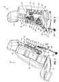
- FIG. 1is a front perspective, partial sectional view of a seat including a zone lumbar system embodying the invention.
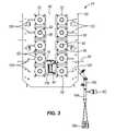
- FIG. 2is a rear perspective, partial sectional view of the seat and the zone lumbar system shown in FIG. 1 .
- FIG. 3is a front view of the zone lumbar system shown in FIG. 1 .
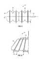
- FIG. 4is a side view of an air cell for use with the zone lumbar system of FIG. 1 in a deflated state.
- FIG. 5is a side view of the air cell of FIG. 4 in a partially inflated state.
- FIG. 6is a side view of the air cell of FIG. 4 in a fully inflated state.
- FIG. 7is a side view of a comfort button for use with the air cell of FIG. 5 .
- FIG. 8is a side view of another embodiment of an air cell for use with the zone lumbar system of FIG. 1 .
- FIG. 9is an enlarged rear perspective view of a portion of the zone lumbar system shown in FIG. 1 .
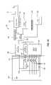
- FIG. 10is a schematic of a control module for use with the zone lumbar system shown in FIG. 1 .
- FIG. 11is a front perspective view of the zone lumbar system shown in FIG. 1 including a plurality of air cells in different inflation states.
- FIGS. 12A-12Fillustrate different inflation states of the zone lumbar system shown in FIG. 1 .
- FIG. 13is a front view of another embodiment of a zone lumbar system.
- FIG. 14is a front view of yet another embodiment of a zone lumbar system.
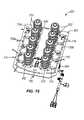
- FIG. 15is a front perspective view of still another embodiment of a zone lumbar system.
- FIGS. 1 and 2illustrate a seat 20 including a zone lumbar system 24 embodying the invention.
- the seat 20is a driver or passenger seat of an automobile and includes a frame 28 , a bottom portion 32 , a back support portion 36 , and a head rest 40 .
- the seat 20may be, for example, an airplane seat, a train seat, a home recliner, or the like.
- the lumbar system 24is installed within a cavity 44 in the back support portion 36 to provide support to a seat occupant sitting in the seat 20 .
- another zone lumbar systemmay additionally or alternatively be positioned and installed within the bottom portion 32 of the seat 20 .
- the illustrated lumbar system 24is a zone lumbar massage system operable to function in both a static support mode and in a dynamic massage mode.
- the lumbar system 24includes a frame 48 , a plurality of air cells 52 , a pump 56 , a control module 60 , and a blower 64 .
- the frame 48is coupled to the seat 20 and includes a first side 68 that faces a seat occupant sitting in the seat 20 and a second side 72 that faces away from the seat occupant.
- the frame 48or mat, is a generally flat and solid substrate that may be composed of, for example, wood, metal, and/or a polymeric material.
- the frame 48may be a wire frame (see FIG. 13 ) or may be composed of a different material or combination of materials.
- the illustrated frame 48is shaped and sized to fit within the cavity 44 in the back support portion 36 and provides a mounting location for the other components of the lumbar system 24 .
- An opening 76extends through the frame 48 from the first side 68 to the second side 72 , and allows the blower 64 to provide an air flow between the first side 68 of the frame 48 and an outer surface 80 of the seat 20 .
- the frame 48also includes a suspension system 84 (e.g., wire hooks and/or support members) extending across and outwardly from the frame 48 to provide additional support to the frame 48 and to facilitate coupling the lumbar system 24 to the frame 28 of the seat 20 .
- a suspension system 84e.g., wire hooks and/or support members
- the air cells 52are mounted to the first side 68 of the lumbar frame 48 and face the outer surface 80 of the seat 20 .
- the illustrated air cells 52may be coupled to the frame 48 by, for example, rivets, staples, adhesives, VELCRO, tape, stitching, and/or loop and lock fasteners. Additionally or alternatively, the air cells 52 may be pocketed in foam that is coupled to the frame 48 . In the illustrated embodiment, ten air cells 52 are coupled to the frame 48 . In other embodiments, fewer or more air cells 52 may be coupled to the frame 48 . In the embodiment shown in FIG. 3 , the air cells 52 are generally symmetrically arranged in two columns along the first side 68 of the frame 48 .
- the air cells 52may be arranged in other generally symmetrical patterns on the first side 68 of the frame 48 (see FIG. 14 ). In still other embodiments, the air cells 52 may be arranged asymmetrically or randomly on the first side 68 of the frame 48 .
- each air cell 52is generally cylindrically shaped and includes a plurality of bladders 88 .
- the air cells 52may be other shapes (e.g., cubical, pyramidal, conical, dog-bone, oblong, or the like) and/or each air cell 52 may have a different shape.
- the illustrated air cells 52are inflatable from a fully deflated state ( FIG. 4 ) to a fully inflated state ( FIG. 6 ).
- the bladders 88are in communication with one another and are variably inflatable to an infinite number of intermediate states or positions, such as the position shown in FIG. 5 , in an accordion-like manner.
- each air cell 52includes four bladders 88 .
- each air cell 52may include fewer or more bladders 88 such that the air cells 52 may extend away from the frame 48 by a greater or lesser amount.
- the illustrated air cells 52may also include a comfort button 92 ( FIG. 3 ) coupled to an end face 96 of the corresponding air cell 52 .
- the comfort buttons 92generally face a seat occupant sitting in the seat 20 and provide a soft pad at the end faces 96 of the cells 52 .
- the illustrated comfort buttons 92are generally hemi-spherically shaped and are composed of a relatively soft, compressible material such as, for example, foam.
- the comfort buttons 92may have, for example, generally cylindrical, pyramidal, or cubical shapes, or may be composed of a more rigid material to provide more localized pressure, particularly during massage operations.
- the comfort buttons 92are variably inflatable with the air cells 52 between a fully deflated state ( FIG. 5 ) and a fully inflated state ( FIG. 7 ).
- balancing straps 100are coupled (e.g., stitched, glued, stapled, etc.) to one of the air cells 52 and to the frame 48 .
- the balancing, or limiter, straps 100control expansion of the corresponding air cell 52 as the cell 52 inflates from the deflated state to the fully inflated state.
- the lumbar system 24may include separate balancing straps 100 coupled to each air cell 52 , to some of the air cells 52 , or to none of the air cells 52 . As shown in FIG.
- the balancing straps 100control expansion of the air cell 52 in a direction that is non-perpendicular and non-linear relative to the frame 48 .
- the end face 96 of the air cell 52is non-parallel to the first side 68 of the frame 48 when the cell 52 is inflated, contouring at least a portion of the lumbar system 24 for a seat occupant sitting in the seat 20 .
- the pump 56is mounted to the second side 72 of the frame 48 adjacent to the control module 60 , although the pump 56 could also be mounted to another portion of the frame 48 or seat 20 that is hidden from view of vehicle passengers.
- the illustrated pump 56may be, for example, any suitable positive displacement pump, diaphragm pump, reciprocating pump, or the like that is operable to pressurize air.
- An air supply hose 104or conduit, extends from the pump 56 and is in communication with the control module 60 to direct pressurized air from the pump 56 to the control module 60 .
- a motor driver 108FIG. 10 ) of the control module 60 supplies power to and controls the pump 56 to activate and deactivate the pump 56 as needed.
- the illustrated control module 60is also mounted to the second side 72 of the frame 48 adjacent to the pump 56 , but could also be mounted to another portion of the frame 56 or seat 20 that is hidden from view of vehicle passengers.
- the control module 60includes a manifold 112 to receive pressurized air from the pump 56 and a plurality of valves 116 (e.g., solenoid valves) coupled to the manifold 112 .
- the illustrated valves 116are coupled directly to the manifold 112 and are independently actuated (e.g., opened or closed) to independently inflate and/or deflate the corresponding air cell 52 .
- control module 60may include two separate valves 116 for each air cell 52 such that each valve 116 either inflates or deflates the corresponding cell 52 .
- some air cells 52may be fluidly linked such that multiple air cells 52 may be operated by the same valve or valves 116 .
- a plurality of air outlet conduits 120extends from the valves 116 to direct pressurized air from the manifold 112 to each of the air cells 52 independently.
- the conduits 120are flexible hoses that are removably coupled to the air cells 52 and the control module 60 .
- the conduits 120may be passageways that are integrally formed or molded into the frame 48 .
- a single air outlet conduitmay extend from the manifold 112 and direct air to valves that are coupled directly to the air cells 52 (see FIG. 15 ).
- the control module 60includes a microcontroller 124 , a voltage regulator 128 , the motor driver 108 , a current feed 132 , a valve controller 136 , an analog input circuit 140 , and a digital input circuit 144 .
- the microcontroller 124sends and receives signals to and from the other components of the control module 60 to control operation of the lumbar system 24 and, in particular, inflation and deflation of the air cells 52 .
- the voltage regulator 128is electrically coupled to the microcontroller 124 , the analog input circuit 140 , and the digital input circuit 144 .
- the regulator 128helps maintain a constant or appropriate input voltage to the microcontroller 124 and the circuits 140 , 144 from a power supply 148 (e.g., a car battery or alternator).
- the current feed 132is electrically coupled to the microcontroller 124 and the motor driver 108 .
- the current feed 132regulates power to the pump 56 through the motor driver 108 such that the driver 108 powers (e.g., turns on) the pump 56 on as desired.
- the valve controller 136is electrically coupled to the microcontroller 124 and the valves 116 ( FIG. 9 ).
- the controller 136controls actuation of the valves 116 between an open position and a closed position to help inflate, deflate, or maintain the air pressure within the cells 52 .
- the valve controller 136may independently control the actuation of the valves 116 to each position.
- the control module 60includes a second valve controller 152 to control the actuation of valves on a remote or second lumbar system (e.g., valves located on a lumbar system in the bottom portion 32 of the seat 20 ).
- the second valve controller 152allows multiple lumbar systems within the seat 20 to be controlled and regulated by a single control module.
- the analog and digital input circuits 140 , 144are electrically coupled to the microcontroller 124 and receive input signals from an operator control 156 .
- the operator control 156is an external device that is mounted to the seat 20 , a dashboard, or another vehicle panel and includes a plurality of switches 160 that are actuatable by a seat occupant using the seat 20 .
- the switches 160adjust the current settings of the zone lumbar system 24 to change between the static support mode and the dynamic massage mode.
- the switches 160also allow the seat occupant to make many changes to the lumbar system 24 while in either mode.
- the seat occupantwhen in the support mode, can actuate one or more of the switches 160 to adjust the inflation amount in one or more of the air cells 52 in a particular zone (e.g., upper back, lower back, sides, etc.). Actuating one of the switches 160 can also change the current inflation states of the air cells 52 to a preset or saved static support position.
- the seat occupantcan actuate one or more of the switches 160 to adjust the speed of the massaging motion, the timing of the massaging motion, the direction of the massaging motion, or the like. Actuating one of the switches 160 can also freeze (i.e., stop) the massaging motion at a static position that the seat occupant finds particularly comfortable.
- the illustrated control module 60further includes two pressure sensors 164 , 168 .
- the pressure sensors 164 , 168are electrically connected to the microcontroller 124 and monitor air pressure within the lumbar system 24 .
- each pressure sensor 164 , 168may monitor the pressure within one particular air cell 52 or group of air cells 52 .
- the air pressureprovides an indication of the amount of inflation of the air cells 52 .
- the pressure sensors 164 , 168may therefore help set the inflation amount of the air cells 52 at each of the various static support positions and during the dynamic massage motions. For example, if the pressure exceeds a predetermined threshold, the microcontroller 124 can activate a relief valve to relieve pressure from the cell 52 or group of cells 52 .
- the pressure sensors 164 , 168can notify the microcontroller 124 if the pressure in the cell 52 or group of cells 52 drops below the desired or programmed pressure level. The microcontroller 124 can then activate the pump 56 and the corresponding valve(s) 116 to increase the pressure within the cell(s) 52 .
- the control module 60may include a separate pressure sensor for each air cell 52 .
- the blower 64is mounted to the second side 72 of the frame 48 adjacent to the opening 76 ( FIG. 3 ). Similar to the pump 56 , the blower 64 is coupled to and controlled by the control module 60 , but may alternatively be coupled directly to and controlled by the operator control 156 ( FIG. 10 ). In some embodiments, the blower 64 may be omitted entirely.
- the illustrated blower 64includes a housing 172 , a fan (not shown) positioned within the housing 172 , and a nozzle 176 coupled to the housing 172 in communication with the fan. The fan draws ambient air into the housing 172 and propels an air flow into the nozzle 176 .
- the nozzle 176directs the air flow through the opening 76 in the frame 48 toward the outer surface 80 of the seat 20 .
- the air flow between the first side 68 of the frame 48 and the outer surface 80ventilates the seat 20 for enhanced seat occupant comfort.
- the blower 64includes a heating element and/or a cooling element positioned in the housing 172 or the nozzle 176 .
- the heating and cooling elementsheat, cool, or otherwise condition the air flow as the fan propels the air flow out of the nozzle 176 .
- a wiring harness 180is coupled to the control module 60 and extends outwardly from the lumbar frame 48 .
- the wiring harness 180provides a single point connection for the power supply 148 ( FIG. 10 ) and the operator control 156 ( FIG. 10 ) to electrically connect to the pump 56 , the control module 60 , and the blower 64 .
- the illustrated wiring harness 180includes a connector portion 184 that extends away from the frame 48 .
- the connector portion 184includes a first electrical connector 188 that connects to the power supply 148 and a second electrical connector 192 that connects to the operator control 156 .
- the connectors 188 , 192are standard sized electrical plugs that removably couple to the power supply 148 and the controller 156 to facilitate installation of the lumbar system 24 in the seat 20 .
- FIGS. 11-12Fillustrate by way of example the zone lumbar system 24 in different operating positions.
- each of the air cells 52is independently inflatable to a variety of different states.
- the illustrated air cells 52are only inflated to three different states (e.g., fully deflated, halfway inflated, and fully inflated), it should be readily apparent that the air cells 52 are inflatable to an infinite number of positions between the fully deflated state and the fully inflated state.
- the air cells 52are inflated to various static support positions to provide support to particular areas or zones for a seat occupant. For example, the support position shown in FIG. 12D provides extra support to the lower back of the seat occupant, the support position shown in FIG. 12E provides extra support to the mid back of the seat occupant, and the support position shown in FIG. 12F provides extra support to the upper back of the seat occupant.
- cycling through the static positions shown in FIGS. 12D-12F (and/or the static positions shown in FIGS. 12A-12C ) in substantially any orderprovides different types of massaging motions or effects for a seat occupant.
- the massaging motionsmay occur in a preset pattern or may be relatively random.
- the operator control 156FIG. 10 ) allows the seat occupant to adjust the speed, timing, and direction of the massaging motions and even freeze the massaging motion at a comfortable static support position.
- the zone lumbar system 24includes a flexible contour member 196 .
- the flexible contour member 196is coupled to the frame 48 and substantially covers the air cells 52 .
- the contour member 196may be, for example, a fabric layer or a foam pad that stretches and deflects to generally match the current positions of the air cells 52 .
- the contour member 196evenly and smoothly distributes the support provided by the air cells 52 to the outer surface 80 of the seat 20 to reduce a seat occupant's perception of each individual air cell 52 , thereby providing the sensation of a smooth area of support.
- FIG. 13illustrates a zone lumbar 224 system according to another embodiment of the invention.
- the illustrated lumbar system 224is similar to the lumbar system 24 shown in FIGS. 1-12 and like parts have been given the same reference numbers plus 200 .
- the illustrated zone lumbar system 224includes a frame 248 , a plurality of air cells 252 , a pump 256 , a control module 260 , and a blower 264 .
- the air cells 252are mounted to a first side 268 of the frame 248 .
- the pump 256 , the control module 260 , and the blower 264are mounted to a second side of the frame 248 substantially opposite the first side 268 .
- the frame 248is a wire frame such that the air cells 252 , the pump 256 , the control module 260 , and the blower 264 are mounted directly to wire cross members rather than to a substantially solid substrate.
- the wire frame 248reduces the overall size and weight of the lumbar system 224 .
- the wire frame 248also facilitates running air conduits 320 between the air cells 252 and the control module 260 by not requiring clearance holes to be manufactured or formed in the frame 248 .
- FIG. 14illustrates a zone lumbar system 424 according to another embodiment of the invention.
- the illustrated lumbar system 424is similar to the lumbar system 24 shown in FIGS. 1-12 and like parts have been given the same reference numbers plus 400 .
- the illustrated zone lumbar system 424includes a frame 448 , a plurality of air cells 452 , a pump (not shown), a control module (not shown), and a blower 464 .
- the air cells 452are mounted to a first side 468 of the frame 448 .
- the pump, the control module, and the blower 464are mounted to a second side of the frame 448 substantially opposite the first side 468 .
- the lumbar system 424includes twelve air cells 452 that are symmetrically arranged in a non-linear pattern on the frame 448 . Similar to the lumbar system 24 discussed above, in other embodiments, the lumbar system 424 may alternatively include fewer or more air cells 452 that are symmetrically or asymmetrical arranged in other patterns on the first side 468 of the frame 448 .
- FIG. 15illustrates a zone lumbar system 624 according to another embodiment of the invention.
- the illustrated lumbar system 624is similar to the lumbar system 24 shown in FIGS. 1-12 and like parts have been given the same reference numbers plus 600 .
- the illustrated zone lumbar system 624includes a frame 648 , a plurality of air cells 652 , a pump (not shown), a control module (not shown), and a blower 664 .
- the air cells 652are mounted to a first side 668 of the frame 648 .
- the pump, the control module, and the blower 664are mounted to a second side of the frame 648 substantially opposite the first side 668 .
- the control moduleincludes a single air outlet conduit 720 that extends from a manifold of the control module toward the air cells 652 .
- the outlet conduit 720includes two branch conduits 720 A, 720 B that run substantially parallel to the air cells 652 positioned on the first side 668 of the frame 648 .
- Valves 716are mounted to the first side 668 of the frame 648 adjacent to each air cell 652 .
- Each valve 716regulates communication between one of the branches 720 A, 720 B and a corresponding air cell 652 .
- the illustrated valves 716are independently actuatable to inflate and/or deflate the air cells 652 .
- the illustrated lumbar system 624includes ten valves 716 corresponding to the ten air cells 652 . In other embodiments, the lumbar system 624 may include fewer or more valves 716 to match the number of air cells 652 mounted to the frame 648 .
- the lumbar system 624may include twice as many valves 716 as air cells 652 such that one valve is in communication with one of the air cells 652 to inflate the cell 652 and a second valve is in communication with the same air cell 652 to deflate the cell 652 .
Landscapes
- Engineering & Computer Science (AREA)
- Aviation & Aerospace Engineering (AREA)
- Transportation (AREA)
- Mechanical Engineering (AREA)
- Health & Medical Sciences (AREA)
- Rehabilitation Therapy (AREA)
- Pain & Pain Management (AREA)
- Physical Education & Sports Medicine (AREA)
- Epidemiology (AREA)
- Life Sciences & Earth Sciences (AREA)
- Animal Behavior & Ethology (AREA)
- General Health & Medical Sciences (AREA)
- Public Health (AREA)
- Veterinary Medicine (AREA)
- Chair Legs, Seat Parts, And Backrests (AREA)
- Seats For Vehicles (AREA)
- Massaging Devices (AREA)
Abstract
Description
Claims (37)
Priority Applications (2)
| Application Number | Priority Date | Filing Date | Title |
|---|---|---|---|
| US12/412,229US8162398B2 (en) | 2009-03-26 | 2009-03-26 | Zone lumbar massage system |
| PCT/CA2010/000350WO2010108254A1 (en) | 2009-03-26 | 2010-03-15 | Single-unit installable air bladder lumbar massage system for chair |
Applications Claiming Priority (1)
| Application Number | Priority Date | Filing Date | Title |
|---|---|---|---|
| US12/412,229US8162398B2 (en) | 2009-03-26 | 2009-03-26 | Zone lumbar massage system |
Publications (2)
| Publication Number | Publication Date |
|---|---|
| US20100244504A1 US20100244504A1 (en) | 2010-09-30 |
| US8162398B2true US8162398B2 (en) | 2012-04-24 |
Family
ID=42780091
Family Applications (1)
| Application Number | Title | Priority Date | Filing Date |
|---|---|---|---|
| US12/412,229Expired - Fee RelatedUS8162398B2 (en) | 2009-03-26 | 2009-03-26 | Zone lumbar massage system |
Country Status (2)
| Country | Link |
|---|---|
| US (1) | US8162398B2 (en) |
| WO (1) | WO2010108254A1 (en) |
Cited By (24)
| Publication number | Priority date | Publication date | Assignee | Title |
|---|---|---|---|---|
| US20110068611A1 (en)* | 2009-09-24 | 2011-03-24 | Toyota Boshoku Kabushiki Kaisha | Vehicle seat |
| US20170028163A1 (en)* | 2015-07-30 | 2017-02-02 | Toyota Jidosha Kabushiki Kaisha | Vehicle seat |
| CN106564412A (en)* | 2015-10-08 | 2017-04-19 | 李尔公司 | Adjustable seat assembly |
| CN108297771A (en)* | 2016-09-23 | 2018-07-20 | 丰田自动车株式会社 | car seat |
| US20190106040A1 (en)* | 2017-10-10 | 2019-04-11 | Continental Automotive Gmbh | Pneumatic device and method for manufacturing the same |
| US10293725B2 (en) | 2016-05-27 | 2019-05-21 | Lear Corporation | Seat support layer assembly |
| US20190255977A1 (en)* | 2016-07-11 | 2019-08-22 | Continental Automotive Gmbh | Method for producing an adjusting device for a vehicle seat, and adjusting device |
| US20190308537A1 (en)* | 2016-07-11 | 2019-10-10 | Conti Temic Microelectronic Gmbh | Pneumatic device |
| US10743668B2 (en)* | 2016-09-23 | 2020-08-18 | Aisin Seiki Kabushiki Kaisha | Intake/exhaust valve device and vehicular seat device |
| DE102019220267A1 (en)* | 2019-12-19 | 2021-06-24 | Volkswagen Aktiengesellschaft | Vehicle seat for a motor vehicle |
| US11135946B2 (en)* | 2018-05-16 | 2021-10-05 | Autodesk, Inc. | Extensively reconfigurable vehicle seat design |
| US11369203B2 (en) | 2020-02-10 | 2022-06-28 | X-Chair, LLC | Chair assemblies, systems, and apparatuses having integrated technologies, and related methods |
| US20220203879A1 (en)* | 2019-04-29 | 2022-06-30 | Conti Temic Microelectronic Gmbh | Seat control device and vehicle seat having such a seat control device |
| US20220348125A1 (en)* | 2021-04-30 | 2022-11-03 | Ford Global Technologies, Llc | Polyhedral body of an articulation assembly for a vehicle seat |
| US11648859B2 (en)* | 2014-05-19 | 2023-05-16 | Ts Tech Co., Ltd. | Vehicle seat |
| US20240198880A1 (en)* | 2022-12-20 | 2024-06-20 | Lear Corporation | Alternative width massage |
| US20240217419A1 (en)* | 2023-01-02 | 2024-07-04 | Faurecia Autositze Gmbh | Module support arrangement |
| US12139057B1 (en)* | 2023-10-18 | 2024-11-12 | Gentherm Incorporated | Comfort assembly for a vehicle seat |
| DE102023205618A1 (en)* | 2023-06-15 | 2024-12-19 | Volkswagen Aktiengesellschaft | Seat part arrangement for a vehicle seat, vehicle seat, motor vehicle |
| DE102023118190A1 (en)* | 2023-07-10 | 2025-01-16 | Faurecia Autositze Gmbh | vehicle seat |
| US20250178506A1 (en)* | 2023-11-30 | 2025-06-05 | Lear Corporation | Massage bladder assembly |
| US12326742B2 (en) | 2022-12-22 | 2025-06-10 | Lear Corporation | Valve and actuator assembly for a fluid system in a vehicle seat assembly |
| US12337738B2 (en) | 2022-11-09 | 2025-06-24 | Lear Corporation | Fluid system for a vehicle seat assembly |
| WO2025188939A1 (en) | 2024-03-06 | 2025-09-12 | Gentherm Incorporated | Suspension plate assembly for pneumatics |
Families Citing this family (73)
| Publication number | Priority date | Publication date | Assignee | Title |
|---|---|---|---|---|
| DE102007053119A1 (en)* | 2007-11-08 | 2009-05-14 | Bayerische Motoren Werke Aktiengesellschaft | Method and device for adjusting a seat and seat |
| WO2009089647A1 (en)* | 2008-01-14 | 2009-07-23 | Han-Chung Hsu | Chair adapted to adjust according to person's sitting-posture vertebral curve (i) |
| DE102010000390A1 (en)* | 2010-02-11 | 2011-08-11 | Forschungszentrum Jülich GmbH, 52428 | Apparatus and method for treating a patient with vibration, tactile and / or thermal implants |
| US8969703B2 (en) | 2010-09-13 | 2015-03-03 | Tempronics, Inc. | Distributed thermoelectric string and insulating panel |
| KR20130116322A (en)* | 2011-01-25 | 2013-10-23 | 광동 자오칭 엘앤브이 코. 엘티디. | Inflatable massage head and massage device comprising the same |
| KR101305565B1 (en) | 2011-06-08 | 2013-09-09 | 현대다이모스(주) | Acoustic Active Seat Apparatus |
| KR20140045408A (en) | 2011-07-06 | 2014-04-16 | 템프로닉스, 인크. | Integration of distributed thermoelectric heating and cooling |
| DE102011117927B4 (en)* | 2011-11-09 | 2017-06-14 | Faurecia Autositze Gmbh | Automotive seat |
| LU92011B1 (en) | 2012-05-30 | 2013-12-02 | Iee Sarl | Vehicle seat suspension mat |
| LU92012B1 (en)* | 2012-05-30 | 2013-12-02 | Iee Sarl | Vehicle seat suspension mat |
| DE102012211392B4 (en)* | 2012-07-02 | 2022-07-21 | Conti Temic Microelectronic Gmbh | Control element for a vehicle seat, vehicle seat and method for producing a control element |
| US9638442B2 (en) | 2012-08-07 | 2017-05-02 | Tempronics, Inc. | Medical, topper, pet wireless, and automated manufacturing of distributed thermoelectric heating and cooling |
| US9676310B2 (en) | 2012-09-25 | 2017-06-13 | Faurecia Automotive Seating, Llc | Vehicle seat with thermal device |
| JP5962490B2 (en)* | 2012-12-19 | 2016-08-03 | トヨタ紡織株式会社 | Vehicle seat |
| GB2512136A (en)* | 2013-03-21 | 2014-09-24 | Daimler Ag | Seat apparatus for a vehicle |
| CN105848964B (en) | 2013-11-04 | 2020-01-03 | 坦普罗尼克斯公司 | Design of thermoelectric strings, plates and envelopes for function and durability |
| US9987961B2 (en) | 2014-06-09 | 2018-06-05 | Lear Corporation | Adjustable seat assembly |
| US10328823B2 (en) | 2014-06-09 | 2019-06-25 | Lear Corporation | Adjustable seat assembly |
| FR3024683B1 (en) | 2014-08-08 | 2018-02-23 | Faurecia Sieges D'automobile | THERMAL DEVICE FOR SEAT OF MOTOR VEHICLE |
| CN104354618A (en)* | 2014-10-24 | 2015-02-18 | 苏州中航中振汽车饰件有限公司 | Car seat with circulating airbag groups |
| US9333889B1 (en)* | 2014-11-10 | 2016-05-10 | Lear Corporation | Seat assembly having an inflatable bladder and a method of assembly |
| US9981577B2 (en) | 2015-01-19 | 2018-05-29 | Lear Corporation | Thoracic air bladder assembly |
| WO2016138364A1 (en)* | 2015-02-27 | 2016-09-01 | Faurecia Automotive Seating, Llc | Seats with thermal devices |
| WO2016141501A1 (en)* | 2015-03-12 | 2016-09-15 | 惠州市唐群电子有限公司 | Gradual adjustment system of lumbar support of seat |
| CN106032117B (en)* | 2015-03-12 | 2018-05-08 | 惠州市唐群座椅科技股份有限公司 | The progressive adjustments system of Seat lumbar |
| US10004655B2 (en)* | 2015-04-17 | 2018-06-26 | Neurobotics Llc | Robotic sports performance enhancement and rehabilitation apparatus |
| US9845026B2 (en) | 2015-05-19 | 2017-12-19 | Lear Corporation | Adjustable seat assembly |
| US9884570B2 (en) | 2015-05-19 | 2018-02-06 | Lear Corporation | Adjustable seat assembly |
| DE102015217989B4 (en)* | 2015-06-17 | 2021-07-22 | Adient Luxembourg Holding S.À R.L. | Vehicle seat |
| US9661928B2 (en) | 2015-09-29 | 2017-05-30 | Lear Corporation | Air bladder assembly for seat bottoms of seat assemblies |
| CH711796A1 (en)* | 2015-11-18 | 2017-05-31 | Lantal Textiles Ag | Pneumatic cushion with pump unit. |
| US9827888B2 (en) | 2016-01-04 | 2017-11-28 | Lear Corporation | Seat assemblies with adjustable side bolster actuators |
| JP6788179B2 (en)* | 2016-05-31 | 2020-11-25 | テイ・エス テック株式会社 | Vehicle seat |
| US10363852B2 (en)* | 2016-09-15 | 2019-07-30 | Ford Global Technologies, Llc | Apparatus and method for customizing a vehicle seat |
| CA3013671C (en)* | 2016-10-19 | 2023-01-24 | B/E Aerospace, Inc. | Passenger seat having side sleep support assembly |
| US11504293B2 (en) | 2016-11-08 | 2022-11-22 | Lear Corporation | Seat assembly having massage bladders with reduced pressure sensor count |
| US10358065B2 (en) | 2016-12-23 | 2019-07-23 | Leggett & Platt Canada Co. | Pneumatic four way lumbar |
| DE102017103315B4 (en)* | 2017-02-17 | 2024-12-12 | Lear Corporation | Pneumatic linear drive for contour or shape adjustment of a vehicle component and vehicle component with a corresponding pneumatic linear drive |
| US10518685B2 (en)* | 2017-03-08 | 2019-12-31 | Ts Tech Co., Ltd. | Conveyance seat |
| US10434918B2 (en)* | 2017-04-11 | 2019-10-08 | Ford Global Technologies, Llc | Pneumatically actuated seat bolster |
| DE102017111429B4 (en)* | 2017-05-24 | 2023-10-26 | Alfmeier Präzision SE | Device for adjusting the contour of a seat, in particular a vehicle seat, and seat, in particular a vehicle seat, with such a device |
| DE102017213484B4 (en)* | 2017-08-03 | 2021-07-15 | Lear Corporation | Seat assembly and method of forming a seat assembly |
| DE102017117856A1 (en)* | 2017-08-07 | 2019-02-07 | Joyson Safety Systems Germany Gmbh | Vehicle seat arrangements for a motor vehicle |
| US20190143856A1 (en)* | 2017-11-13 | 2019-05-16 | Gulfstream Aerospace Corporation | Seat assembly that includes a modular foam arrangement and a pneumatic bladder sub-assembly and method for fabricating the same |
| CA3028693C (en)* | 2018-01-02 | 2021-06-08 | Dowco, Inc. | Adjustable seat for a vehicle |
| US11883358B2 (en) | 2018-03-05 | 2024-01-30 | Leggett & Platt Canada Co. | Pneumatic massage system |
| JP7065992B2 (en)* | 2018-03-05 | 2022-05-12 | レゲット・アンド・プラット・カナダ・カンパニー | Pneumatic massage system |
| US11432995B2 (en) | 2018-08-29 | 2022-09-06 | Leggett & Platt Canada Co. | Pneumatic massage |
| JP6935785B2 (en)* | 2018-05-21 | 2021-09-15 | トヨタ紡織株式会社 | Air bag air supply / exhaust device |
| KR102096379B1 (en)* | 2018-08-28 | 2020-04-03 | 주식회사 디에스시동탄 | Lumbar support assembly |
| US11039975B2 (en) | 2018-08-29 | 2021-06-22 | Leggett & Platt Canada Co. | Pneumatic massage |
| KR102654936B1 (en)* | 2018-11-19 | 2024-04-04 | 현대자동차주식회사 | Multi-function footrest apparatus for vehicle |
| DE102019201591B4 (en)* | 2019-02-07 | 2025-05-28 | Bühler Motor GmbH | Airplane seat massage system and airplane seat with a massage system |
| EP3705348B1 (en)* | 2019-03-04 | 2021-05-19 | KA Group AG | Massage cell stack for a vehicle seat |
| US10765219B1 (en)* | 2019-04-17 | 2020-09-08 | Ka Group Ag | Lounger having a pneumatic lounging system |
| KR102750653B1 (en)* | 2019-06-11 | 2025-01-06 | 현대자동차주식회사 | System and method for reducing fatigue of driver in the seat of vehicle |
| CN110329516A (en)* | 2019-07-31 | 2019-10-15 | 苏州标图高级座椅有限公司 | A kind of aircraft seat with neck massaging function |
| US11787319B2 (en)* | 2019-09-02 | 2023-10-17 | Adient Us Llc | Apparatus for a seat, more particularly a vehicle seat, for mobilizing at least one region of a spinal column of a seat occupant, method for sequentially driving an apparatus and seat, more particularly vehicle seat |
| EP4110649A1 (en) | 2020-02-24 | 2023-01-04 | Schukra Berndorf GmbH | Pneumatic bladder arrangement for a seat and method for manufacturing the same |
| CN113942468A (en)* | 2020-07-15 | 2022-01-18 | 采埃孚汽车科技(上海)有限公司 | Pneumatic seat control system, control method, and computer-readable medium for vehicle |
| CN112109612A (en)* | 2020-09-29 | 2020-12-22 | 微赛技术(北京)有限公司 | A car seat pneumatic lumbar massage system |
| US11524613B2 (en)* | 2020-12-28 | 2022-12-13 | Lear Corporation | Ventilated seat with low pressure zone induced airflow |
| US20220273105A1 (en)* | 2021-03-01 | 2022-09-01 | Hhc Changzhou Corporation | Heat and massage system for a furniture piece and a method of operating the same |
| CN114987302A (en)* | 2021-03-01 | 2022-09-02 | 东风安道拓汽车座椅有限公司 | Multifunctional comfortable automobile seat |
| GB2609984B (en) | 2021-08-20 | 2024-05-29 | Thompson Aero Seating Ltd | A vehicle seat |
| KR20230073824A (en)* | 2021-11-19 | 2023-05-26 | 현대자동차주식회사 | Mesh integrated seat pad assembly |
| CN217286269U (en)* | 2021-12-28 | 2022-08-26 | 厦门睿康科技有限公司 | Multifunctional massage device |
| CN114668626B (en)* | 2022-02-15 | 2023-06-20 | 燕山大学 | A pose-adjustable rigid-flexible coupling waist rehabilitation robot |
| US12214707B2 (en)* | 2022-03-29 | 2025-02-04 | Lear Corporation | Seat assembly with massage |
| US12358411B2 (en)* | 2022-04-01 | 2025-07-15 | Lear Corporation | Vehicle seat subassemblies |
| DE112023003256T5 (en)* | 2022-07-29 | 2025-05-15 | Lear Corporation | Reusable lumbar support system |
| US12319180B2 (en)* | 2023-04-06 | 2025-06-03 | Rivian Ip Holdings, Llc | Integrated lumbar mat system |
| DE102023136243A1 (en)* | 2023-12-21 | 2025-06-26 | Faurecia Autositze Gmbh | Module carrier arrangement |
Citations (32)
| Publication number | Priority date | Publication date | Assignee | Title |
|---|---|---|---|---|
| US3983640A (en) | 1974-11-06 | 1976-10-05 | The Singer Company | Advanced G seat for aircraft simulation |
| US4629253A (en)* | 1986-01-15 | 1986-12-16 | Williams Theodore M | Seat occupant-activated underseat support air-cushion |
| US4634179A (en) | 1982-07-31 | 1987-01-06 | Aisin Seiki Kabushiki Kaisha | Air lumbar support device |
| US4655505A (en) | 1984-12-13 | 1987-04-07 | Nhk Spring Co., Ltd. | Pneumatically controlled seat for vehicle |
| US4707027A (en) | 1986-02-28 | 1987-11-17 | General Motors Corporation | Pneumatically cushioned vehicle seat(s) and apparatus and method to adjust the same |
| US4981131A (en) | 1988-03-14 | 1991-01-01 | Hazard Rowland G | Passive motion back support |
| US5076643A (en) | 1990-08-20 | 1991-12-31 | Lear Seating Corporation | Lumbar support |
| US5135282A (en) | 1989-08-18 | 1992-08-04 | Man Nutzfahrzeuge Aktiengesellschaft | Motor vehicle seat back |
| US5320409A (en) | 1990-11-29 | 1994-06-14 | Nissan Motor Co., Ltd. | Seat apparatus for vehicle |
| US5379471A (en) | 1991-01-28 | 1995-01-10 | Holdredge; Terry K. | Pneumatic wheel chair cushion for reducing ischemic injury |
| US5467489A (en)* | 1994-01-21 | 1995-11-21 | Cchen; Cchung-Pao | Air permeable cushion |
| US5509155A (en)* | 1994-08-04 | 1996-04-23 | Creative Medical, Inc. | Alternating low air loss pressure overlay for patient bedside chair |
| US5558398A (en) | 1993-11-08 | 1996-09-24 | Santos; James P. | Self-adjusting seating system |
| US5678891A (en) | 1995-11-14 | 1997-10-21 | Peter W. Linley | Dynamic combination seating and backrest support system |
| US5762618A (en) | 1995-06-14 | 1998-06-09 | Kabushiki Kaisha Fuji Iryoki | Chair-type air massage device |
| US5806115A (en)* | 1992-07-22 | 1998-09-15 | Princeton Products | Portable, integrated, universally adjustable position control system |
| US5836647A (en) | 1997-05-20 | 1998-11-17 | Turman; Ben | Vehicle seat with shock absorption |
| US5967608A (en) | 1998-05-06 | 1999-10-19 | Bytec Incorporated | Pneumatic lumbar adjustment system |
| US6074006A (en) | 1999-05-21 | 2000-06-13 | Magna Interior Systems, Inc. | Automotive seat with pneumatic pelvic stabilization |
| US6088643A (en) | 1994-06-24 | 2000-07-11 | Mccord Winn Textron Inc. | Interactive, individually controlled, multiple bladder seating comfort adjustment system |
| US6203105B1 (en) | 1999-08-20 | 2001-03-20 | Mccord Winn Textron Inc. | Vehicle impact responsive multiple bladder seating and headrest system and method |
| US6212719B1 (en) | 1997-10-10 | 2001-04-10 | D2Rm Corp. | Air massager cushioning device |
| US6551450B1 (en) | 1997-10-10 | 2003-04-22 | D2Rm Corp. | Unique air and sonic massaging apparatus |
| US20030230917A1 (en) | 2002-06-18 | 2003-12-18 | Erich Dorfler | Contour-adjustable seat and modular support unit |
| EP1447070A1 (en) | 2003-02-11 | 2004-08-18 | Johnson Controls Seating Cap S.r.l. | Seat with massaging apparatus and process for performing a massage |
| US20040174056A1 (en) | 2003-03-06 | 2004-09-09 | Sears Manufacturing Company | Inflatable seat cushion |
| US6823549B1 (en)* | 2003-05-14 | 2004-11-30 | Donna N. Hampton | Alternating pressure cushion with inflatable lumbar support |
| US6916300B2 (en) | 2002-11-14 | 2005-07-12 | Bowles Fluidics Corporation | Seat massager |
| US20060049678A1 (en) | 2002-09-14 | 2006-03-09 | Daimlerchrysler Ag | Vehicle seat having a massage function and contour adjustment |
| US20060217644A1 (en) | 2005-01-19 | 2006-09-28 | Takashi Ozaki | Vehicle seats |
| US7267404B2 (en)* | 2003-09-27 | 2007-09-11 | Alfmeier Praezision Ag | Arrangement for controlling a fluid volume in shape changing elements of seats |
| WO2007121874A1 (en) | 2006-04-19 | 2007-11-01 | Bayerische Motoren Werke Aktiengesellschaft | Seat |
- 2009
- 2009-03-26USUS12/412,229patent/US8162398B2/ennot_activeExpired - Fee Related
- 2010
- 2010-03-15WOPCT/CA2010/000350patent/WO2010108254A1/enactiveApplication Filing
Patent Citations (33)
| Publication number | Priority date | Publication date | Assignee | Title |
|---|---|---|---|---|
| US3983640A (en) | 1974-11-06 | 1976-10-05 | The Singer Company | Advanced G seat for aircraft simulation |
| US4634179A (en) | 1982-07-31 | 1987-01-06 | Aisin Seiki Kabushiki Kaisha | Air lumbar support device |
| US4655505A (en) | 1984-12-13 | 1987-04-07 | Nhk Spring Co., Ltd. | Pneumatically controlled seat for vehicle |
| US4629253A (en)* | 1986-01-15 | 1986-12-16 | Williams Theodore M | Seat occupant-activated underseat support air-cushion |
| US4707027A (en) | 1986-02-28 | 1987-11-17 | General Motors Corporation | Pneumatically cushioned vehicle seat(s) and apparatus and method to adjust the same |
| US4981131A (en) | 1988-03-14 | 1991-01-01 | Hazard Rowland G | Passive motion back support |
| US5135282A (en) | 1989-08-18 | 1992-08-04 | Man Nutzfahrzeuge Aktiengesellschaft | Motor vehicle seat back |
| US5076643A (en) | 1990-08-20 | 1991-12-31 | Lear Seating Corporation | Lumbar support |
| US5320409A (en) | 1990-11-29 | 1994-06-14 | Nissan Motor Co., Ltd. | Seat apparatus for vehicle |
| US5379471A (en) | 1991-01-28 | 1995-01-10 | Holdredge; Terry K. | Pneumatic wheel chair cushion for reducing ischemic injury |
| US5806115A (en)* | 1992-07-22 | 1998-09-15 | Princeton Products | Portable, integrated, universally adjustable position control system |
| US5558398A (en) | 1993-11-08 | 1996-09-24 | Santos; James P. | Self-adjusting seating system |
| US5467489A (en)* | 1994-01-21 | 1995-11-21 | Cchen; Cchung-Pao | Air permeable cushion |
| US6088643A (en) | 1994-06-24 | 2000-07-11 | Mccord Winn Textron Inc. | Interactive, individually controlled, multiple bladder seating comfort adjustment system |
| US6098000A (en) | 1994-06-24 | 2000-08-01 | Mccord Winn Textron Inc. | Interactive, individually controlled, multiple bladder seating comfort adjustment system and method |
| US5509155A (en)* | 1994-08-04 | 1996-04-23 | Creative Medical, Inc. | Alternating low air loss pressure overlay for patient bedside chair |
| US5762618A (en) | 1995-06-14 | 1998-06-09 | Kabushiki Kaisha Fuji Iryoki | Chair-type air massage device |
| US5678891A (en) | 1995-11-14 | 1997-10-21 | Peter W. Linley | Dynamic combination seating and backrest support system |
| US5836647A (en) | 1997-05-20 | 1998-11-17 | Turman; Ben | Vehicle seat with shock absorption |
| US6212719B1 (en) | 1997-10-10 | 2001-04-10 | D2Rm Corp. | Air massager cushioning device |
| US6551450B1 (en) | 1997-10-10 | 2003-04-22 | D2Rm Corp. | Unique air and sonic massaging apparatus |
| US5967608A (en) | 1998-05-06 | 1999-10-19 | Bytec Incorporated | Pneumatic lumbar adjustment system |
| US6074006A (en) | 1999-05-21 | 2000-06-13 | Magna Interior Systems, Inc. | Automotive seat with pneumatic pelvic stabilization |
| US6203105B1 (en) | 1999-08-20 | 2001-03-20 | Mccord Winn Textron Inc. | Vehicle impact responsive multiple bladder seating and headrest system and method |
| US20030230917A1 (en) | 2002-06-18 | 2003-12-18 | Erich Dorfler | Contour-adjustable seat and modular support unit |
| US20060049678A1 (en) | 2002-09-14 | 2006-03-09 | Daimlerchrysler Ag | Vehicle seat having a massage function and contour adjustment |
| US6916300B2 (en) | 2002-11-14 | 2005-07-12 | Bowles Fluidics Corporation | Seat massager |
| EP1447070A1 (en) | 2003-02-11 | 2004-08-18 | Johnson Controls Seating Cap S.r.l. | Seat with massaging apparatus and process for performing a massage |
| US20040174056A1 (en) | 2003-03-06 | 2004-09-09 | Sears Manufacturing Company | Inflatable seat cushion |
| US6823549B1 (en)* | 2003-05-14 | 2004-11-30 | Donna N. Hampton | Alternating pressure cushion with inflatable lumbar support |
| US7267404B2 (en)* | 2003-09-27 | 2007-09-11 | Alfmeier Praezision Ag | Arrangement for controlling a fluid volume in shape changing elements of seats |
| US20060217644A1 (en) | 2005-01-19 | 2006-09-28 | Takashi Ozaki | Vehicle seats |
| WO2007121874A1 (en) | 2006-04-19 | 2007-11-01 | Bayerische Motoren Werke Aktiengesellschaft | Seat |
Non-Patent Citations (1)
| Title |
|---|
| International Search Report and Written Opinion of the International Searching Authority, International Patent Application No. PCT/CA2010/000350, mailed Jun. 25, 2010. |
Cited By (40)
| Publication number | Priority date | Publication date | Assignee | Title |
|---|---|---|---|---|
| US8608243B2 (en)* | 2009-09-24 | 2013-12-17 | Toyota Boshoku Kabushiki Kaisha | Vehicle seat |
| US20110068611A1 (en)* | 2009-09-24 | 2011-03-24 | Toyota Boshoku Kabushiki Kaisha | Vehicle seat |
| US11648859B2 (en)* | 2014-05-19 | 2023-05-16 | Ts Tech Co., Ltd. | Vehicle seat |
| US11945350B2 (en) | 2014-05-19 | 2024-04-02 | Ts Tech Co., Ltd. | Vehicle seat |
| US20170028163A1 (en)* | 2015-07-30 | 2017-02-02 | Toyota Jidosha Kabushiki Kaisha | Vehicle seat |
| US9814859B2 (en)* | 2015-07-30 | 2017-11-14 | Toyota Jidosha Kabushiki Kaisha | Vehicle seat |
| CN106564412A (en)* | 2015-10-08 | 2017-04-19 | 李尔公司 | Adjustable seat assembly |
| US9758079B2 (en)* | 2015-10-08 | 2017-09-12 | Lear Corporation | Adjustable seat assembly |
| CN106564412B (en)* | 2015-10-08 | 2019-01-18 | 李尔公司 | Adjustable Seat Assembly |
| US10293725B2 (en) | 2016-05-27 | 2019-05-21 | Lear Corporation | Seat support layer assembly |
| US11014478B2 (en) | 2016-05-27 | 2021-05-25 | Lear Corporation | Seat support layer assembly |
| US20190255977A1 (en)* | 2016-07-11 | 2019-08-22 | Continental Automotive Gmbh | Method for producing an adjusting device for a vehicle seat, and adjusting device |
| US20190308537A1 (en)* | 2016-07-11 | 2019-10-10 | Conti Temic Microelectronic Gmbh | Pneumatic device |
| US10752145B2 (en)* | 2016-07-11 | 2020-08-25 | Conti Temic Microelectronic Gmbh | Pneumatic device |
| US10793041B2 (en)* | 2016-07-11 | 2020-10-06 | Continental Automotive Gmbh | Method for producing an adjusting device for a vehicle seat, and adjusting device |
| CN108297771B (en)* | 2016-09-23 | 2020-07-07 | 丰田自动车株式会社 | Vehicle seat |
| US10743668B2 (en)* | 2016-09-23 | 2020-08-18 | Aisin Seiki Kabushiki Kaisha | Intake/exhaust valve device and vehicular seat device |
| US10220756B2 (en)* | 2016-09-23 | 2019-03-05 | Toyota Jidosha Kabushiki Kaisha | Vehicle seat |
| CN108297771A (en)* | 2016-09-23 | 2018-07-20 | 丰田自动车株式会社 | car seat |
| US20190106040A1 (en)* | 2017-10-10 | 2019-04-11 | Continental Automotive Gmbh | Pneumatic device and method for manufacturing the same |
| US10696202B2 (en)* | 2017-10-10 | 2020-06-30 | Continental Automotive Gmbh | Pneumatic device and method for manufacturing the same |
| US11135946B2 (en)* | 2018-05-16 | 2021-10-05 | Autodesk, Inc. | Extensively reconfigurable vehicle seat design |
| US11548411B2 (en) | 2018-05-16 | 2023-01-10 | Autodesk, Inc. | Extensively reconfigurable vehicle seat design |
| US20220203879A1 (en)* | 2019-04-29 | 2022-06-30 | Conti Temic Microelectronic Gmbh | Seat control device and vehicle seat having such a seat control device |
| US11865950B2 (en)* | 2019-04-29 | 2024-01-09 | Conti Temic Microelectronic Gmbh | Seat control device and vehicle seat having such a seat control device |
| DE102019220267B4 (en) | 2019-12-19 | 2022-03-17 | Volkswagen Aktiengesellschaft | Vehicle seat for a motor vehicle |
| DE102019220267A1 (en)* | 2019-12-19 | 2021-06-24 | Volkswagen Aktiengesellschaft | Vehicle seat for a motor vehicle |
| US11369203B2 (en) | 2020-02-10 | 2022-06-28 | X-Chair, LLC | Chair assemblies, systems, and apparatuses having integrated technologies, and related methods |
| US12376681B2 (en) | 2020-02-10 | 2025-08-05 | X-Chair, LLC | Chair assemblies, systems, and apparatuses having integrated technologies, and related methods |
| US20220348125A1 (en)* | 2021-04-30 | 2022-11-03 | Ford Global Technologies, Llc | Polyhedral body of an articulation assembly for a vehicle seat |
| US11590872B2 (en)* | 2021-04-30 | 2023-02-28 | Ford Global Technologies, Llc | Polyhedral body of an articulation assembly for a vehicle seat |
| US12337738B2 (en) | 2022-11-09 | 2025-06-24 | Lear Corporation | Fluid system for a vehicle seat assembly |
| US20240198880A1 (en)* | 2022-12-20 | 2024-06-20 | Lear Corporation | Alternative width massage |
| US12326742B2 (en) | 2022-12-22 | 2025-06-10 | Lear Corporation | Valve and actuator assembly for a fluid system in a vehicle seat assembly |
| US20240217419A1 (en)* | 2023-01-02 | 2024-07-04 | Faurecia Autositze Gmbh | Module support arrangement |
| DE102023205618A1 (en)* | 2023-06-15 | 2024-12-19 | Volkswagen Aktiengesellschaft | Seat part arrangement for a vehicle seat, vehicle seat, motor vehicle |
| DE102023118190A1 (en)* | 2023-07-10 | 2025-01-16 | Faurecia Autositze Gmbh | vehicle seat |
| US12139057B1 (en)* | 2023-10-18 | 2024-11-12 | Gentherm Incorporated | Comfort assembly for a vehicle seat |
| US20250178506A1 (en)* | 2023-11-30 | 2025-06-05 | Lear Corporation | Massage bladder assembly |
| WO2025188939A1 (en) | 2024-03-06 | 2025-09-12 | Gentherm Incorporated | Suspension plate assembly for pneumatics |
Also Published As
| Publication number | Publication date |
|---|---|
| WO2010108254A1 (en) | 2010-09-30 |
| US20100244504A1 (en) | 2010-09-30 |
Similar Documents
| Publication | Publication Date | Title |
|---|---|---|
| US8162398B2 (en) | Zone lumbar massage system | |
| US8226166B2 (en) | Seating element and seating system | |
| US5860699A (en) | Adjustable lumbar seating system | |
| CA2244955C (en) | Adjustable comfort seat | |
| US9340131B1 (en) | Head restraint with a multi-cell bladder assembly | |
| US8011729B2 (en) | Seating element and seating system | |
| US20030030319A1 (en) | Cellular cushion vehicle seat system | |
| US11766961B2 (en) | Device for adjusting softness of seat, device for adjusting comfort of seat, and vehicle seat | |
| CN109318770A (en) | A kind of more air bag comfort systems of seat of integrated lumbar support and multiple spot massage | |
| EP3575144A1 (en) | Dynamic pneumatic support system | |
| JP2000510029A (en) | Interactive multi-cell seat comfort adjustment system | |
| CN112477716A (en) | Automobile seat with self-adaptive adjusting function and control method thereof | |
| US20250303948A1 (en) | Vehicle seat having a heater and a plurality of air cells, and a method for manufacturing the same | |
| CN111728839B (en) | Waist holds in palm massage system and contains its massage armchair | |
| EP3526076B1 (en) | Adjustable seat | |
| JPH08224137A (en) | Air mat for seat | |
| CN209581238U (en) | A kind of more air bag comfort systems of seat of integrated lumbar support and multiple spot massage | |
| JP5139937B2 (en) | Car interior massage device | |
| CN212593015U (en) | Waist support massage system and massage seat comprising same | |
| CN215204561U (en) | Automobile seat with self-adaptive adjusting function | |
| JP2001252316A (en) | Air massage equipment | |
| CN221340324U (en) | Integrated automobile seat controller | |
| US11964601B2 (en) | Vehicle seat having a fluid chamber unit | |
| CN216231861U (en) | Sleeping berth device and vehicle | |
| KR20240133103A (en) | Device for providing air pressure and vibration on the vehicle seat |
Legal Events
| Date | Code | Title | Description |
|---|---|---|---|
| AS | Assignment | Owner name:SCHUKRA OF NORTH AMERICA LTD., ONTARIO Free format text:ASSIGNMENT OF ASSIGNORS INTEREST;ASSIGNORS:COLJA, RENATO;MCMILLEN, ROBERT J.;KOOPMAN, JOHN;REEL/FRAME:022590/0119 Effective date:20090325 | |
| AS | Assignment | Owner name:SCHUKRA OF NORTH AMERICA CO., ONTARIO Free format text:CHANGE OF NAME;ASSIGNOR:SCHUKRA OF NORTH AMERICA LTD.;REEL/FRAME:027553/0526 Effective date:20110929 | |
| STCF | Information on status: patent grant | Free format text:PATENTED CASE | |
| AS | Assignment | Owner name:LEGGETT & PLATT CANADA CO., CANADA Free format text:MERGER;ASSIGNOR:SCHUKRA OF NORTH AMERICA CO.;REEL/FRAME:032298/0300 Effective date:20130101 | |
| FPAY | Fee payment | Year of fee payment:4 | |
| FEPP | Fee payment procedure | Free format text:MAINTENANCE FEE REMINDER MAILED (ORIGINAL EVENT CODE: REM.); ENTITY STATUS OF PATENT OWNER: LARGE ENTITY | |
| LAPS | Lapse for failure to pay maintenance fees | Free format text:PATENT EXPIRED FOR FAILURE TO PAY MAINTENANCE FEES (ORIGINAL EVENT CODE: EXP.); ENTITY STATUS OF PATENT OWNER: LARGE ENTITY | |
| STCH | Information on status: patent discontinuation | Free format text:PATENT EXPIRED DUE TO NONPAYMENT OF MAINTENANCE FEES UNDER 37 CFR 1.362 | |
| FP | Lapsed due to failure to pay maintenance fee | Effective date:20200424 |