US8162085B2 - Hydro-mechanical clutch for a hybrid transmission and method for operating the same - Google Patents
Hydro-mechanical clutch for a hybrid transmission and method for operating the sameDownload PDFInfo
- Publication number
- US8162085B2 US8162085B2US12/427,844US42784409AUS8162085B2US 8162085 B2US8162085 B2US 8162085B2US 42784409 AUS42784409 AUS 42784409AUS 8162085 B2US8162085 B2US 8162085B2
- Authority
- US
- United States
- Prior art keywords
- clutch
- engine
- recited
- actuator
- assembly
- Prior art date
- Legal status (The legal status is an assumption and is not a legal conclusion. Google has not performed a legal analysis and makes no representation as to the accuracy of the status listed.)
- Expired - Fee Related, expires
Links
Images


Classifications
- B—PERFORMING OPERATIONS; TRANSPORTING
- B60—VEHICLES IN GENERAL
- B60W—CONJOINT CONTROL OF VEHICLE SUB-UNITS OF DIFFERENT TYPE OR DIFFERENT FUNCTION; CONTROL SYSTEMS SPECIALLY ADAPTED FOR HYBRID VEHICLES; ROAD VEHICLE DRIVE CONTROL SYSTEMS FOR PURPOSES NOT RELATED TO THE CONTROL OF A PARTICULAR SUB-UNIT
- B60W20/00—Control systems specially adapted for hybrid vehicles
- B—PERFORMING OPERATIONS; TRANSPORTING
- B60—VEHICLES IN GENERAL
- B60K—ARRANGEMENT OR MOUNTING OF PROPULSION UNITS OR OF TRANSMISSIONS IN VEHICLES; ARRANGEMENT OR MOUNTING OF PLURAL DIVERSE PRIME-MOVERS IN VEHICLES; AUXILIARY DRIVES FOR VEHICLES; INSTRUMENTATION OR DASHBOARDS FOR VEHICLES; ARRANGEMENTS IN CONNECTION WITH COOLING, AIR INTAKE, GAS EXHAUST OR FUEL SUPPLY OF PROPULSION UNITS IN VEHICLES
- B60K6/00—Arrangement or mounting of plural diverse prime-movers for mutual or common propulsion, e.g. hybrid propulsion systems comprising electric motors and internal combustion engines
- B60K6/20—Arrangement or mounting of plural diverse prime-movers for mutual or common propulsion, e.g. hybrid propulsion systems comprising electric motors and internal combustion engines the prime-movers consisting of electric motors and internal combustion engines, e.g. HEVs
- B60K6/22—Arrangement or mounting of plural diverse prime-movers for mutual or common propulsion, e.g. hybrid propulsion systems comprising electric motors and internal combustion engines the prime-movers consisting of electric motors and internal combustion engines, e.g. HEVs characterised by apparatus, components or means specially adapted for HEVs
- B60K6/38—Arrangement or mounting of plural diverse prime-movers for mutual or common propulsion, e.g. hybrid propulsion systems comprising electric motors and internal combustion engines the prime-movers consisting of electric motors and internal combustion engines, e.g. HEVs characterised by apparatus, components or means specially adapted for HEVs characterised by the driveline clutches
- B60K6/387—Actuated clutches, i.e. clutches engaged or disengaged by electric, hydraulic or mechanical actuating means
- B—PERFORMING OPERATIONS; TRANSPORTING
- B60—VEHICLES IN GENERAL
- B60K—ARRANGEMENT OR MOUNTING OF PROPULSION UNITS OR OF TRANSMISSIONS IN VEHICLES; ARRANGEMENT OR MOUNTING OF PLURAL DIVERSE PRIME-MOVERS IN VEHICLES; AUXILIARY DRIVES FOR VEHICLES; INSTRUMENTATION OR DASHBOARDS FOR VEHICLES; ARRANGEMENTS IN CONNECTION WITH COOLING, AIR INTAKE, GAS EXHAUST OR FUEL SUPPLY OF PROPULSION UNITS IN VEHICLES
- B60K6/00—Arrangement or mounting of plural diverse prime-movers for mutual or common propulsion, e.g. hybrid propulsion systems comprising electric motors and internal combustion engines
- B60K6/20—Arrangement or mounting of plural diverse prime-movers for mutual or common propulsion, e.g. hybrid propulsion systems comprising electric motors and internal combustion engines the prime-movers consisting of electric motors and internal combustion engines, e.g. HEVs
- B60K6/42—Arrangement or mounting of plural diverse prime-movers for mutual or common propulsion, e.g. hybrid propulsion systems comprising electric motors and internal combustion engines the prime-movers consisting of electric motors and internal combustion engines, e.g. HEVs characterised by the architecture of the hybrid electric vehicle
- B60K6/48—Parallel type
- B—PERFORMING OPERATIONS; TRANSPORTING
- B60—VEHICLES IN GENERAL
- B60W—CONJOINT CONTROL OF VEHICLE SUB-UNITS OF DIFFERENT TYPE OR DIFFERENT FUNCTION; CONTROL SYSTEMS SPECIALLY ADAPTED FOR HYBRID VEHICLES; ROAD VEHICLE DRIVE CONTROL SYSTEMS FOR PURPOSES NOT RELATED TO THE CONTROL OF A PARTICULAR SUB-UNIT
- B60W10/00—Conjoint control of vehicle sub-units of different type or different function
- B60W10/02—Conjoint control of vehicle sub-units of different type or different function including control of driveline clutches
- B60W10/023—Fluid clutches
- B—PERFORMING OPERATIONS; TRANSPORTING
- B60—VEHICLES IN GENERAL
- B60W—CONJOINT CONTROL OF VEHICLE SUB-UNITS OF DIFFERENT TYPE OR DIFFERENT FUNCTION; CONTROL SYSTEMS SPECIALLY ADAPTED FOR HYBRID VEHICLES; ROAD VEHICLE DRIVE CONTROL SYSTEMS FOR PURPOSES NOT RELATED TO THE CONTROL OF A PARTICULAR SUB-UNIT
- B60W10/00—Conjoint control of vehicle sub-units of different type or different function
- B60W10/04—Conjoint control of vehicle sub-units of different type or different function including control of propulsion units
- B60W10/06—Conjoint control of vehicle sub-units of different type or different function including control of propulsion units including control of combustion engines
- B—PERFORMING OPERATIONS; TRANSPORTING
- B60—VEHICLES IN GENERAL
- B60W—CONJOINT CONTROL OF VEHICLE SUB-UNITS OF DIFFERENT TYPE OR DIFFERENT FUNCTION; CONTROL SYSTEMS SPECIALLY ADAPTED FOR HYBRID VEHICLES; ROAD VEHICLE DRIVE CONTROL SYSTEMS FOR PURPOSES NOT RELATED TO THE CONTROL OF A PARTICULAR SUB-UNIT
- B60W10/00—Conjoint control of vehicle sub-units of different type or different function
- B60W10/04—Conjoint control of vehicle sub-units of different type or different function including control of propulsion units
- B60W10/08—Conjoint control of vehicle sub-units of different type or different function including control of propulsion units including control of electric propulsion units, e.g. motors or generators
- B—PERFORMING OPERATIONS; TRANSPORTING
- B60—VEHICLES IN GENERAL
- B60W—CONJOINT CONTROL OF VEHICLE SUB-UNITS OF DIFFERENT TYPE OR DIFFERENT FUNCTION; CONTROL SYSTEMS SPECIALLY ADAPTED FOR HYBRID VEHICLES; ROAD VEHICLE DRIVE CONTROL SYSTEMS FOR PURPOSES NOT RELATED TO THE CONTROL OF A PARTICULAR SUB-UNIT
- B60W30/00—Purposes of road vehicle drive control systems not related to the control of a particular sub-unit, e.g. of systems using conjoint control of vehicle sub-units
- B60W30/18—Propelling the vehicle
- B60W30/18009—Propelling the vehicle related to particular drive situations
- B60W30/18027—Drive off, accelerating from standstill
- B—PERFORMING OPERATIONS; TRANSPORTING
- B60—VEHICLES IN GENERAL
- B60W—CONJOINT CONTROL OF VEHICLE SUB-UNITS OF DIFFERENT TYPE OR DIFFERENT FUNCTION; CONTROL SYSTEMS SPECIALLY ADAPTED FOR HYBRID VEHICLES; ROAD VEHICLE DRIVE CONTROL SYSTEMS FOR PURPOSES NOT RELATED TO THE CONTROL OF A PARTICULAR SUB-UNIT
- B60W30/00—Purposes of road vehicle drive control systems not related to the control of a particular sub-unit, e.g. of systems using conjoint control of vehicle sub-units
- B60W30/18—Propelling the vehicle
- B60W30/192—Mitigating problems related to power-up or power-down of the driveline, e.g. start-up of a cold engine
- F—MECHANICAL ENGINEERING; LIGHTING; HEATING; WEAPONS; BLASTING
- F16—ENGINEERING ELEMENTS AND UNITS; GENERAL MEASURES FOR PRODUCING AND MAINTAINING EFFECTIVE FUNCTIONING OF MACHINES OR INSTALLATIONS; THERMAL INSULATION IN GENERAL
- F16D—COUPLINGS FOR TRANSMITTING ROTATION; CLUTCHES; BRAKES
- F16D25/00—Fluid-actuated clutches
- F16D25/06—Fluid-actuated clutches in which the fluid actuates a piston incorporated in, i.e. rotating with the clutch
- F16D25/062—Fluid-actuated clutches in which the fluid actuates a piston incorporated in, i.e. rotating with the clutch the clutch having friction surfaces
- F16D25/063—Fluid-actuated clutches in which the fluid actuates a piston incorporated in, i.e. rotating with the clutch the clutch having friction surfaces with clutch members exclusively moving axially
- F16D25/0635—Fluid-actuated clutches in which the fluid actuates a piston incorporated in, i.e. rotating with the clutch the clutch having friction surfaces with clutch members exclusively moving axially with flat friction surfaces, e.g. discs
- F16D25/0638—Fluid-actuated clutches in which the fluid actuates a piston incorporated in, i.e. rotating with the clutch the clutch having friction surfaces with clutch members exclusively moving axially with flat friction surfaces, e.g. discs with more than two discs, e.g. multiple lamellae
- F—MECHANICAL ENGINEERING; LIGHTING; HEATING; WEAPONS; BLASTING
- F16—ENGINEERING ELEMENTS AND UNITS; GENERAL MEASURES FOR PRODUCING AND MAINTAINING EFFECTIVE FUNCTIONING OF MACHINES OR INSTALLATIONS; THERMAL INSULATION IN GENERAL
- F16D—COUPLINGS FOR TRANSMITTING ROTATION; CLUTCHES; BRAKES
- F16D25/00—Fluid-actuated clutches
- F16D25/10—Clutch systems with a plurality of fluid-actuated clutches
- F—MECHANICAL ENGINEERING; LIGHTING; HEATING; WEAPONS; BLASTING
- F16—ENGINEERING ELEMENTS AND UNITS; GENERAL MEASURES FOR PRODUCING AND MAINTAINING EFFECTIVE FUNCTIONING OF MACHINES OR INSTALLATIONS; THERMAL INSULATION IN GENERAL
- F16H—GEARING
- F16H63/00—Control outputs from the control unit to change-speed- or reversing-gearings for conveying rotary motion or to other devices than the final output mechanism
- F16H63/02—Final output mechanisms therefor; Actuating means for the final output mechanisms
- F16H63/30—Constructional features of the final output mechanisms
- F16H63/3023—Constructional features of the final output mechanisms the final output mechanisms comprising elements moved by fluid pressure
- F16H63/3026—Constructional features of the final output mechanisms the final output mechanisms comprising elements moved by fluid pressure comprising friction clutches or brakes
- B—PERFORMING OPERATIONS; TRANSPORTING
- B60—VEHICLES IN GENERAL
- B60K—ARRANGEMENT OR MOUNTING OF PROPULSION UNITS OR OF TRANSMISSIONS IN VEHICLES; ARRANGEMENT OR MOUNTING OF PLURAL DIVERSE PRIME-MOVERS IN VEHICLES; AUXILIARY DRIVES FOR VEHICLES; INSTRUMENTATION OR DASHBOARDS FOR VEHICLES; ARRANGEMENTS IN CONNECTION WITH COOLING, AIR INTAKE, GAS EXHAUST OR FUEL SUPPLY OF PROPULSION UNITS IN VEHICLES
- B60K6/00—Arrangement or mounting of plural diverse prime-movers for mutual or common propulsion, e.g. hybrid propulsion systems comprising electric motors and internal combustion engines
- B60K6/20—Arrangement or mounting of plural diverse prime-movers for mutual or common propulsion, e.g. hybrid propulsion systems comprising electric motors and internal combustion engines the prime-movers consisting of electric motors and internal combustion engines, e.g. HEVs
- B60K6/22—Arrangement or mounting of plural diverse prime-movers for mutual or common propulsion, e.g. hybrid propulsion systems comprising electric motors and internal combustion engines the prime-movers consisting of electric motors and internal combustion engines, e.g. HEVs characterised by apparatus, components or means specially adapted for HEVs
- B60K6/26—Arrangement or mounting of plural diverse prime-movers for mutual or common propulsion, e.g. hybrid propulsion systems comprising electric motors and internal combustion engines the prime-movers consisting of electric motors and internal combustion engines, e.g. HEVs characterised by apparatus, components or means specially adapted for HEVs characterised by the motors or the generators
- B60K2006/268—Electric drive motor starts the engine, i.e. used as starter motor
- B—PERFORMING OPERATIONS; TRANSPORTING
- B60—VEHICLES IN GENERAL
- B60L—PROPULSION OF ELECTRICALLY-PROPELLED VEHICLES; SUPPLYING ELECTRIC POWER FOR AUXILIARY EQUIPMENT OF ELECTRICALLY-PROPELLED VEHICLES; ELECTRODYNAMIC BRAKE SYSTEMS FOR VEHICLES IN GENERAL; MAGNETIC SUSPENSION OR LEVITATION FOR VEHICLES; MONITORING OPERATING VARIABLES OF ELECTRICALLY-PROPELLED VEHICLES; ELECTRIC SAFETY DEVICES FOR ELECTRICALLY-PROPELLED VEHICLES
- B60L2240/00—Control parameters of input or output; Target parameters
- B60L2240/40—Drive Train control parameters
- B60L2240/42—Drive Train control parameters related to electric machines
- B60L2240/423—Torque
- B—PERFORMING OPERATIONS; TRANSPORTING
- B60—VEHICLES IN GENERAL
- B60W—CONJOINT CONTROL OF VEHICLE SUB-UNITS OF DIFFERENT TYPE OR DIFFERENT FUNCTION; CONTROL SYSTEMS SPECIALLY ADAPTED FOR HYBRID VEHICLES; ROAD VEHICLE DRIVE CONTROL SYSTEMS FOR PURPOSES NOT RELATED TO THE CONTROL OF A PARTICULAR SUB-UNIT
- B60W2510/00—Input parameters relating to a particular sub-units
- B60W2510/02—Clutches
- B—PERFORMING OPERATIONS; TRANSPORTING
- B60—VEHICLES IN GENERAL
- B60W—CONJOINT CONTROL OF VEHICLE SUB-UNITS OF DIFFERENT TYPE OR DIFFERENT FUNCTION; CONTROL SYSTEMS SPECIALLY ADAPTED FOR HYBRID VEHICLES; ROAD VEHICLE DRIVE CONTROL SYSTEMS FOR PURPOSES NOT RELATED TO THE CONTROL OF A PARTICULAR SUB-UNIT
- B60W2510/00—Input parameters relating to a particular sub-units
- B60W2510/06—Combustion engines, Gas turbines
- B60W2510/0685—Engine crank angle
- B—PERFORMING OPERATIONS; TRANSPORTING
- B60—VEHICLES IN GENERAL
- B60W—CONJOINT CONTROL OF VEHICLE SUB-UNITS OF DIFFERENT TYPE OR DIFFERENT FUNCTION; CONTROL SYSTEMS SPECIALLY ADAPTED FOR HYBRID VEHICLES; ROAD VEHICLE DRIVE CONTROL SYSTEMS FOR PURPOSES NOT RELATED TO THE CONTROL OF A PARTICULAR SUB-UNIT
- B60W2710/00—Output or target parameters relating to a particular sub-units
- B60W2710/06—Combustion engines, Gas turbines
- B60W2710/0666—Engine torque
- B—PERFORMING OPERATIONS; TRANSPORTING
- B60—VEHICLES IN GENERAL
- B60W—CONJOINT CONTROL OF VEHICLE SUB-UNITS OF DIFFERENT TYPE OR DIFFERENT FUNCTION; CONTROL SYSTEMS SPECIALLY ADAPTED FOR HYBRID VEHICLES; ROAD VEHICLE DRIVE CONTROL SYSTEMS FOR PURPOSES NOT RELATED TO THE CONTROL OF A PARTICULAR SUB-UNIT
- B60W2710/00—Output or target parameters relating to a particular sub-units
- B60W2710/08—Electric propulsion units
- B60W2710/083—Torque
- B—PERFORMING OPERATIONS; TRANSPORTING
- B60—VEHICLES IN GENERAL
- B60Y—INDEXING SCHEME RELATING TO ASPECTS CROSS-CUTTING VEHICLE TECHNOLOGY
- B60Y2400/00—Special features of vehicle units
- B60Y2400/43—Engines
- B60Y2400/435—Supercharger or turbochargers
- F—MECHANICAL ENGINEERING; LIGHTING; HEATING; WEAPONS; BLASTING
- F16—ENGINEERING ELEMENTS AND UNITS; GENERAL MEASURES FOR PRODUCING AND MAINTAINING EFFECTIVE FUNCTIONING OF MACHINES OR INSTALLATIONS; THERMAL INSULATION IN GENERAL
- F16H—GEARING
- F16H63/00—Control outputs from the control unit to change-speed- or reversing-gearings for conveying rotary motion or to other devices than the final output mechanism
- F16H63/02—Final output mechanisms therefor; Actuating means for the final output mechanisms
- F16H63/30—Constructional features of the final output mechanisms
- F16H63/3023—Constructional features of the final output mechanisms the final output mechanisms comprising elements moved by fluid pressure
- F16H63/3026—Constructional features of the final output mechanisms the final output mechanisms comprising elements moved by fluid pressure comprising friction clutches or brakes
- F16H2063/3036—Constructional features of the final output mechanisms the final output mechanisms comprising elements moved by fluid pressure comprising friction clutches or brakes the clutch is actuated by springs and released by a fluid pressure
- Y—GENERAL TAGGING OF NEW TECHNOLOGICAL DEVELOPMENTS; GENERAL TAGGING OF CROSS-SECTIONAL TECHNOLOGIES SPANNING OVER SEVERAL SECTIONS OF THE IPC; TECHNICAL SUBJECTS COVERED BY FORMER USPC CROSS-REFERENCE ART COLLECTIONS [XRACs] AND DIGESTS
- Y02—TECHNOLOGIES OR APPLICATIONS FOR MITIGATION OR ADAPTATION AGAINST CLIMATE CHANGE
- Y02T—CLIMATE CHANGE MITIGATION TECHNOLOGIES RELATED TO TRANSPORTATION
- Y02T10/00—Road transport of goods or passengers
- Y02T10/60—Other road transportation technologies with climate change mitigation effect
- Y02T10/62—Hybrid vehicles
- Y—GENERAL TAGGING OF NEW TECHNOLOGICAL DEVELOPMENTS; GENERAL TAGGING OF CROSS-SECTIONAL TECHNOLOGIES SPANNING OVER SEVERAL SECTIONS OF THE IPC; TECHNICAL SUBJECTS COVERED BY FORMER USPC CROSS-REFERENCE ART COLLECTIONS [XRACs] AND DIGESTS
- Y02—TECHNOLOGIES OR APPLICATIONS FOR MITIGATION OR ADAPTATION AGAINST CLIMATE CHANGE
- Y02T—CLIMATE CHANGE MITIGATION TECHNOLOGIES RELATED TO TRANSPORTATION
- Y02T10/00—Road transport of goods or passengers
- Y02T10/60—Other road transportation technologies with climate change mitigation effect
- Y02T10/64—Electric machine technologies in electromobility
Definitions
- the present inventionrelates generally to transmissions and, more particularly, to a clutch configuration for use in a hybrid transmission
- Air flow into gasoline enginesis regulated via a throttle. More specifically, the throttle adjusts throttle area, which increases or decreases air flow into the engine. As the throttle area increases, the air flow into the engine increases.
- a fuel control systemadjusts the rate that fuel is injected to provide a desired air/fuel mixture to the cylinders. Increasing the amount of air and fuel provided to the cylinders increases the torque output of the engine.
- Hybrid vehiclesare increasing in popularity.
- Hybrid vehiclesgenerally have two power sources.
- the internal combustion engineis a first power source and an electric motor is a second power source.
- the electric motoris used as a power source in city driving where vehicle kinetic energy can be recovered by regenerative braking, converted to electric and chemical form, and stored in a battery, from which the motor is driven.
- the internal combustion engineis most suitable in highway driving, during which wheel braking and opportunities for energy recovery are infrequent, and the engine operates at its greatest efficiency.
- the electric motor and combustion enginemay be used together to transmit power to a transmission input shaft, depending on driving conditions and the magnitude of the battery capacity.
- an enginetypically includes a separate starter motor used for starting the engine when the engine is stopped. Reducing the amount of components in a vehicle reduces the vehicle weight and, therefore, increases the overall range or gas mileage of the vehicle.
- the present disclosureeliminates a conventional starter motor from the vehicle and uses the hybrid electric motor and actuators to start the engine of the vehicle.
- a clutch assemblyincludes a clutch assembly including a first housing comprising a first clutch, a first clutch actuator and a second housing having the first clutch actuator at least partially disposed therein so that said first clutch actuator selectively engages the first clutch.
- the clutch assemblymay be incorporated into a transmission having at least one electric motor therein.
- the motorsmay be used to operate a hybrid electric vehicle.
- a clutch assemblyin one aspect of the disclosure, includes a first clutch and a first clutch actuator for selectively engaging the first clutch.
- the first actuatorhas a first at-rest position engaging the clutch and a hydraulically charged position disengaged from the first clutch.
- the clutch assemblyfurther includes a second clutch actuator having a second at-rest position away disengaged from the first clutch and a second hydraulically charged position engaged with the first clutch.
- a method of starting a vehicle having an engineincludes engaging a first clutch in a transmission with a first clutch actuator when the engine is not started, starting the engine, generating a hydraulic force to move the first clutch actuator after starting the engine, and operating the transmission with a second clutch actuator.
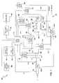
- FIG. 1is a functional block diagram of an exemplary engine system according to the principles of the present disclosure
- FIG. 2is a block diagrammatic view of a hybrid vehicle system
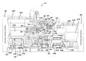
- FIG. 3is an end view of a transmission according to the present disclosure
- FIG. 4is a cutaway view of a transmission wherein the transmission is in the off state and the transmission is starting the engine;
- FIG. 5is a cutaway view of a transmission for the clutch positions after starting of the vehicle
- FIG. 6is a cross-sectional view of a secondary housing according to the present disclosure.
- FIG. 7is a flowchart of a method for starting a hybrid vehicle using the hybrid transmission.
- modulerefers to an Application Specific Integrated Circuit (ASIC), an electronic circuit, a processor (shared, dedicated, or group) and memory that execute one or more software or firmware programs, a combinational logic circuit, and/or other suitable components that provide the described functionality.
- ASICApplication Specific Integrated Circuit
- processorshared, dedicated, or group
- memorythat execute one or more software or firmware programs, a combinational logic circuit, and/or other suitable components that provide the described functionality.
- the engine system 100includes an engine 102 that combusts an air/fuel mixture to produce drive torque for a vehicle based on a driver input module 104 .
- Airis drawn into an intake manifold 110 through a throttle valve 112 .
- the throttle valve 112may include a butterfly valve having a rotatable blade.
- An engine control module (ECM) 114controls a throttle actuator module 116 , which regulates opening of the throttle valve 112 to control the amount of air drawn into the intake manifold 110 .
- ECMengine control module
- Air from the intake manifold 110is drawn into cylinders of the engine 102 .
- the engine 102may include multiple cylinders, for illustration purposes a single representative cylinder 118 is shown.
- the engine 102may include 2, 3, 4, 5, 6, 8, 10, and/or 12 cylinders.
- the ECM 114may instruct a cylinder actuator module 120 to selectively deactivate some of the cylinders, which may improve fuel economy under certain engine operating conditions.
- Air from the intake manifold 110is drawn into the cylinder 118 through an intake valve 122 .
- the ECM 114controls a fuel actuator module 124 , which regulates fuel injection to achieve a desired air/fuel ratio.
- Fuelmay be injected into the intake manifold 110 at a central location or at multiple locations, such as near the intake valve of each of the cylinders. In various implementations not depicted in FIG. 1 , fuel may be injected directly into the cylinders or into mixing chambers associated with the cylinders.
- the fuel actuator module 124may halt injection of fuel to cylinders that are deactivated.
- the injected fuelmixes with air and creates an air/fuel mixture in the cylinder 118 .
- a piston(not shown) within the cylinder 118 compresses the air/fuel mixture.
- a spark actuator module 126energizes a spark plug 128 in the cylinder 118 , which ignites the air/fuel mixture.
- the timing of the sparkmay be specified relative to the time when the piston is at its topmost position, referred to as top dead center (TDC).
- the combustion of the air/fuel mixturedrives the piston down, thereby driving a rotating crankshaft (not shown).
- the pistonthen begins moving up again and expels the byproducts of combustion through an exhaust valve 130 .
- the byproducts of combustionare exhausted from the vehicle via an exhaust system 134 .
- the spark actuator module 126may be controlled by a timing signal indicating how far before or after TDC the spark should be provided. Operation of the spark actuator module 126 may therefore be synchronized with crankshaft rotation. In various implementations, the spark actuator module 126 may halt provision of spark to deactivated cylinders.
- the intake valve 122may be controlled by an intake camshaft 140
- the exhaust valve 130may be controlled by an exhaust camshaft 142 .
- multiple intake camshaftsmay control multiple intake valves per cylinder and/or may control the intake valves of multiple banks of cylinders.
- multiple exhaust camshaftsmay control multiple exhaust valves per cylinder and/or may control exhaust valves for multiple banks of cylinders.
- the cylinder actuator module 120may deactivate the cylinder 118 by disabling opening of the intake valve 122 and/or the exhaust valve 130 .
- the time at which the intake valve 122 is openedmay be varied with respect to piston TDC by an intake cam phaser 148 .
- the time at which the exhaust valve 130 is openedmay be varied with respect to piston TDC by an exhaust cam phaser 150 .
- a phaser actuator module 158controls the intake cam phaser 148 and the exhaust cam phaser 150 based on signals from the ECM 114 . When implemented, variable valve lift may also be controlled by the phaser actuator module 158 .
- the engine system 100may include a boost device that provides pressurized air to the intake manifold 110 .
- FIG. 1shows a turbocharger 160 that includes a hot turbine 160 - 1 that is powered by hot exhaust gases flowing through the exhaust system 134 .
- the turbocharger 160also includes a cold air compressor 160 - 2 , driven by the turbine 160 - 1 , that compresses air leading into the throttle valve 112 .
- a superchargerdriven by the crankshaft, may compress air from the throttle valve 112 and deliver the compressed air to the intake manifold 110 .
- a waste gate 162may allow exhaust gas to bypass the turbocharger 160 , thereby reducing the boost (the amount of intake air compression) of the turbocharger 160 .
- the ECM 114controls the turbocharger 160 via a boost actuator module 164 .
- the boost actuator module 164may modulate the boost of the turbocharger 160 by controlling the position of the waste gate 162 .
- multiple turbochargersmay be controlled by the boost actuator module 164 .
- the turbocharger 160may have variable geometry, which may be controlled by the boost actuator module 164 .
- An intercoolermay dissipate some of the compressed air charge's heat, which is generated as the air is compressed.
- the compressed air chargemay also have absorbed heat because of the air's proximity to the exhaust system 134 .
- the turbine 160 - 1 and the compressor 160 - 2are often attached to each other, placing intake air in close proximity to hot exhaust.
- the engine system 100may include an exhaust gas recirculation (EGR) valve 170 , which selectively redirects exhaust gas back to the intake manifold 110 .
- the EGR valve 170may be located upstream of the turbocharger 160 .
- the EGR valve 170may be controlled by an EGR actuator module 172 .
- the engine system 100may measure the speed of the crankshaft in revolutions per minute (RPM) using an RPM sensor 180 .
- the temperature of the engine coolantmay be measured using an engine coolant temperature (ECT) sensor 182 .
- ECTengine coolant temperature
- the ECT sensor 182may be located within the engine 102 or at other locations where the coolant is circulated, such as a radiator (not shown).
- the pressure within the intake manifold 110may be measured using a manifold absolute pressure (MAP) sensor 184 .
- MAPmanifold absolute pressure
- engine vacuumwhich is the difference between ambient air pressure and the pressure within the intake manifold 110 , may be measured.
- the mass flow rate of air flowing into the intake manifold 110may be measured using a mass air flow (MAF) sensor 186 .
- the MAF sensor 186may be located in a housing that also includes the throttle valve 112 .
- the throttle actuator module 116may monitor the position of the throttle valve 112 using one or more throttle position sensors (TPS) 190 .
- TPSthrottle position sensors
- the ambient temperature of air being drawn into the engine 102may be measured using an intake air temperature (IAT) sensor 192 .
- IATintake air temperature
- the ECM 114may use signals from the sensors to make control decisions for the engine system 100 .
- the ECM 114may communicate with a transmission control module 194 to coordinate shifting gears in a transmission (not shown). For example, the ECM 114 may reduce engine torque during a gear shift.
- the ECM 114may communicate with a hybrid control module 196 to coordinate operation of the engine 102 and an electric motor 198 .
- the hybrid control module 196may control for fuel economy or performance. The vehicle operator may be able to select the mode of operation.
- the electric motor 198may also function as a generator, and may be used to produce electrical energy for use by vehicle electrical systems and/or for storage in a battery.
- various functions of the ECM 114 , the transmission control module 194 , and the hybrid control module 196may be integrated into one or more modules.
- An electronic brake control module 200may also communicate with the engine control module 114 .
- Various torques associated with the electronic braking systemmay be factored into the torque control as will be described below.
- Each system that varies an engine parametermay be referred to as an actuator that receives an actuator value.
- the throttle actuator module 116may be referred to as an actuator and the throttle opening area may be referred to as the actuator value.
- the throttle actuator module 116achieves the throttle opening area by adjusting the angle of the blade of the throttle valve 112 .
- the spark actuator module 126may be referred to as an actuator, while the corresponding actuator value may be the amount of spark advance relative to cylinder TDC.
- Other actuatorsmay include the boost actuator module 164 , the EGR actuator module 172 , the phaser actuator module 158 , the fuel actuator module 124 , and the cylinder actuator module 120 .
- the actuator valuesmay correspond to boost pressure, EGR valve opening area, intake and exhaust cam phaser angles, fueling rate, and number of cylinders activated, respectively.
- the ECM 114may control actuator values in order to generate a desired torque from the engine 102 .
- the vehicleincludes the engine system 100 that includes a crankshaft 212 that is in communication with a hybrid transmission system 214 .
- the hybrid transmission system 214communicates torque to the wheels of a vehicle through a driveline 216 .
- the hybrid transmission system 214includes at least one electric motor 220 , actuators 222 , which may include clutches or the like for engaging and disengaging gears within a transmission 230 . Both the transmission control module 194 and the hybrid control module 196 may be used together to control the hybrid transmission system 214 .
- the transmission control module 194 and the hybrid control module 196are shown as separate elements in FIGS. 1 and 2 . However, the two may be combined as a single control module 240 .
- FIG. 3an end view of a transmission having a main housing 310 and a plurality of secondary housing 312 A, 312 B, and 312 C.
- the secondary housingsare used for stationary piston assemblies. Three secondary housings are illustrated. However, various members of housings may be provided.
- the transmission 214has a first electric motor 220 A and a second electric motor 220 B.
- the motor 220 Aincludes a stator 410 A and a rotor 412 A.
- Motor 220 Bincludes a stator 410 B and a rotor 412 B.
- the hybrid transmission system 214also includes a first planetary gear set 414 A that includes a ring gear 416 A, a sun gear 418 A and planetary gears 420 A.
- the gear set 414 Ais in communication with the transmission shaft 430 through various support components 432 .
- a second gear set 414 Bis provided for communicating torque between the electric motor 220 B and the transmission shaft 430 .
- the second gear setmay also be a planetary gear set that includes a ring gear 416 B, a sun gear 418 B and planetary gears 420 B. The operation of the gear sets 414 A and 414 B will be further described below.
- the hybrid transmission system 214includes a first clutch assembly 440 and a second clutch assembly 442 .
- the first clutch assembly 440is used for both starting the engine 102 of FIG. 1 and for operating the transmission 214 .
- the clutch assembly 442is also used for operating the transmission 214 .
- the first clutch assembly 440includes a spring 444 that acts upon an actuator or piston 446 .
- the spring 444pushes the piston 446 away from the clutch pack 448 . This is the at-rest position.
- the clutch pack 448has disks coupled to a clutch housing 450 and disks 452 in communication with a clutch support 454 .
- the secondary housing 312 Aincludes a pressure port 456 for providing pressure into a cavity formed between the piston 446 and the piston cavity 458 .
- the piston 446is illustrated in a retracted at-rest position so the cavity is not present. The cavity will be illustrated below in FIG. 5 .
- a seal 460seals the piston to the cavity 458 . When hydraulically
- a second piston assembly 470is illustrated.
- the second piston assembly 470includes a spring 472 disposed within a piston cavity 474 .
- the piston cavity 474also includes a spring cavity 476 .
- the piston cavity 474includes a fluid port 478 for providing hydraulic fluid into a piston chamber 480 formed between a first piston 482 and a second piston 484 .
- a first seal 486 disposed on the first piston 482forms a seal within the piston cavity 474 .
- a second seal 488fluidically seals the piston chamber 480 and the piston 484 between the first piston 482 and the outer wall of the piston cavity 474 .
- the piston 484is prevented from moving axially toward the motor B by a stop 492 .
- the spring 472biases the piston 482 axially to engage the disks 448 and 452 to engage. Extension of the spring and thus the housing is an at-rest condition. As will be described below, engagement of the clutch disks 448 and 452 ultimately allow the gear assembly 414 B to provide a starting torque to the engine. Also, the gear assembly 414 A also provides an electric starting torque to the transmission shaft 430 for providing starting torque to the engine.
- a second clutch assembly 500also includes disks 502 and 504 used for engaging and disengaging various gears in the gear set 414 B to provide various drive ratios in a conventional manner. The hydraulically charged position of the piston is away from the clutch.
- the piston assembly 470is illustrated in a retracted position. That is, the piston 482 is retracted from the disks 448 .
- the piston 486is retracted axially towards motor 410 A by providing hydraulic fluid through the port 478 .
- the hydraulic fluid chamber 480expands due to the hydraulic forces therein, the force of the spring 472 is overcome and thus the clutch is in a normal operating position.
- the piston 446is thus allowed to operate the clutch assembly 440 by moving the piston 446 so that the clutch disks 448 , 452 engage.
- the operation of the clutch assembly 440 and 500allow various drive ratios to be provided by the transmission shaft 430 .
- the spring 472pushes the piston 482 into engagement so that the clutch disks 448 and 452 have sufficient friction therebetween.
- the ring gear 416 Bis also fixed into position.
- the sun gear 418 Bis driven by the motor B and thus torque is provided to the transmission shaft 430 .
- the motor Adrives the sun gear 418 A so that torque is transmitted to the transmission shaft 430 .
- the torque provided by the motor 220 A and motor 220 Bprovides a sufficient amount of torque to start the engine system 100 illustrated in FIG. 2 .
- the hybrid transmission system 214ultimately couples the transmission shaft 430 to the crankshaft 212 of the engine system 100 .
- hydraulic fluidis provided through the port 478 to provide a sufficient hydraulic pressure between the pistons 482 and 484 to overcome the force of the spring 472 and thus allow the piston 482 to disengage the disks 448 , 452 .
- the clutches 440 and 500thereafter are allowed to operate the transmission and the gearing in a desired manner.
- a third piston assembly 510is illustrated having a spring 512 that pushes pistons 514 and 516 apart. Hydraulic fluid enters a chamber through a port 518 to move the piston 516 into engagement with the clutch assembly 500 .
- the piston 514remains stationary while the piston 516 moves axially.
- FIG. 6a side view of the secondary housing 312 is illustrated in further detail. This view is provided to illustrate the relative positions of the first piston cavity 458 and the second piston cavity 474 .
- the housing 312may be located using dowel pins or other locating methods.
- the dowel pinsmay be located on the main housing 310 or the secondary housing 312 .
- the dowel pinsnot shown, transfer the torque and the thrust load created when the clutch is applied.
- increased clutch capacity with the same transmission boundary conditionsmay be provided.
- a reduced number of clutch plates or disksare provided in the clutch packs 440 and 500 . Spin loss is also reduced while increasing the fuel efficiency of the vehicle.
- the additional housingallows three pistons to be stacked radially decreasing the transmission length.
- step 610the vehicle is not in use, meaning that the engine is not started.
- step 612the first piston is biased with a first spring torque force to engage the first clutch against a first clutch pack. This essentially prevents the clutch support 454 from moving. A sufficient spring force is provided to prevent the clutch support from moving and therefore the second motor is in communication with the transmission shaft 430 of FIGS. 4 and 5 . Thus, the at-rest position is with the clutch engaged.
- step 614the vehicle is started with the first spring force engaging the disks 448 , 452 of the first clutch 440 .
- step 616when the vehicle is not started, step 614 is again performed in which the first spring force is engaged with the first clutch.
- step 618generates hydraulic pressure to overcome the first spring force.
- the hydraulic pressureis provided between the first piston 482 and the second piston 484 into the hydraulic chamber 480 .
- Enough hydraulic fluidis provided to overcome the spring force and thus retract the piston 482 from engagement with the clutch disks so that the clutch disks 448 and 452 of FIGS. 4 and 5 turn freely. This engagement of the clutch is performed in step 620 .
- step 622the transmission is operated in a normal manner. That is, the piston 446 engages and disengages the first clutch 440 and the second piston 516 engages and disengages the clutch assembly 500 .
- the gear ratio of the transmission shaft 430may be changed relative to an input shaft of the transmission.
Landscapes
- Engineering & Computer Science (AREA)
- Mechanical Engineering (AREA)
- Chemical & Material Sciences (AREA)
- Combustion & Propulsion (AREA)
- Transportation (AREA)
- General Engineering & Computer Science (AREA)
- Automation & Control Theory (AREA)
- Physics & Mathematics (AREA)
- Fluid Mechanics (AREA)
- Hybrid Electric Vehicles (AREA)
Abstract
Description
Claims (20)
Priority Applications (3)
| Application Number | Priority Date | Filing Date | Title |
|---|---|---|---|
| US12/427,844US8162085B2 (en) | 2008-12-24 | 2009-04-22 | Hydro-mechanical clutch for a hybrid transmission and method for operating the same |
| DE102009058732.2ADE102009058732B4 (en) | 2008-12-24 | 2009-12-17 | hybrid vehicle |
| CN200910266376.6ACN101761590B (en) | 2008-12-24 | 2009-12-24 | Hydro-mechanical clutch for a hybrid transmission and method for operating the same |
Applications Claiming Priority (2)
| Application Number | Priority Date | Filing Date | Title |
|---|---|---|---|
| US14066908P | 2008-12-24 | 2008-12-24 | |
| US12/427,844US8162085B2 (en) | 2008-12-24 | 2009-04-22 | Hydro-mechanical clutch for a hybrid transmission and method for operating the same |
Publications (2)
| Publication Number | Publication Date |
|---|---|
| US20100155159A1 US20100155159A1 (en) | 2010-06-24 |
| US8162085B2true US8162085B2 (en) | 2012-04-24 |
Family
ID=42264433
Family Applications (1)
| Application Number | Title | Priority Date | Filing Date |
|---|---|---|---|
| US12/427,844Expired - Fee RelatedUS8162085B2 (en) | 2008-12-24 | 2009-04-22 | Hydro-mechanical clutch for a hybrid transmission and method for operating the same |
Country Status (2)
| Country | Link |
|---|---|
| US (1) | US8162085B2 (en) |
| CN (1) | CN101761590B (en) |
Cited By (3)
| Publication number | Priority date | Publication date | Assignee | Title |
|---|---|---|---|---|
| US20140096641A1 (en)* | 2012-10-05 | 2014-04-10 | Honda Motor Co., Ltd. | Drive device for vehicle |
| US10203005B2 (en) | 2016-11-01 | 2019-02-12 | GM Global Technology Operations LLC | Passive opening low loss clutch pack |
| US10865836B2 (en) | 2015-08-20 | 2020-12-15 | Schaeffler Technologies AG & Co. KG | Clutch device for a hybrid drive system |
Families Citing this family (6)
| Publication number | Priority date | Publication date | Assignee | Title |
|---|---|---|---|---|
| US20140320060A1 (en)* | 2013-04-24 | 2014-10-30 | Aleksander Hrnjak | Vehicle having wind-powered generator |
| JP5942941B2 (en)* | 2013-07-30 | 2016-06-29 | トヨタ自動車株式会社 | Hybrid system |
| DE102015215900A1 (en)* | 2015-08-20 | 2017-02-23 | Schaeffler Technologies AG & Co. KG | Coupling device for hybrid drive |
| USD837851S1 (en)* | 2017-02-17 | 2019-01-08 | Scott A. Schneider | RPM sensor for an automated clutch system |
| KR101834924B1 (en)* | 2017-04-26 | 2018-03-06 | 콘티넨탈 오토모티브 게엠베하 | Method for diagnosing clutch stuck and apparatus thereof |
| USD894248S1 (en)* | 2018-08-31 | 2020-08-25 | Roborus Co., Ltd. | Robot |
Citations (13)
| Publication number | Priority date | Publication date | Assignee | Title |
|---|---|---|---|---|
| US6571654B2 (en)* | 2001-04-05 | 2003-06-03 | New Venture Gear, Inc. | Automated manual transmission with upshift ball ramp synchronizer clutch and downshift ball ramp synchronizer clutch |
| US6672180B2 (en)* | 2001-04-05 | 2004-01-06 | New Venture Gear, Inc. | Manual transmission with upshift and downshift synchronization clutches |
| US6948604B2 (en)* | 2004-01-30 | 2005-09-27 | Magna Drivetrain Of America, Inc. | Hydraulically-actuated pilot clutch type clutch assembly |
| US7002267B2 (en)* | 2004-03-22 | 2006-02-21 | General Motors Corporation | Method and apparatus for cooling a hybrid transmission electric motor |
| US20060199697A1 (en)* | 2003-02-21 | 2006-09-07 | Kirkwood Malcolm E | Torque vectoring device having an electric motor/brake actuator and friction clutch |
| US7189182B2 (en)* | 2001-11-15 | 2007-03-13 | General Motors Corporation | Transmission clutch control system |
| US7194350B2 (en)* | 2002-07-16 | 2007-03-20 | Magna Powertrain Usa, Inc. | Power transfer system regulated using a dithered control signal |
| US7204166B2 (en)* | 2004-11-08 | 2007-04-17 | Eaton Corporation | Dual clutch assembly for a heavy-duty automotive powertrain |
| CN101029663A (en) | 2006-02-28 | 2007-09-05 | 赫尔曼—哈根迈尔Getrag传动机构和齿轮工厂有限公司&两合公司 | Dual clutch device for a dual clutch transmission |
| US7281617B2 (en)* | 2004-02-04 | 2007-10-16 | Magna Powertrain Usa, Inc. | Active torque coupling with hydraulically-actuated rotary clutch actuator |
| US7337886B2 (en)* | 2004-10-19 | 2008-03-04 | Magna Powertrain Usa, Inc. | Torque transfer mechanisms with power-operated clutch actuator |
| US20090250307A1 (en)* | 2008-04-04 | 2009-10-08 | Gm Global Technology Operations, Inc. | Dual apply clutch apparatus for compact electro-mechanical transmission |
| US7896146B2 (en)* | 2006-12-20 | 2011-03-01 | Borgwarner, Inc. | Clutch device utilizing brushless motor |
Family Cites Families (11)
| Publication number | Priority date | Publication date | Assignee | Title |
|---|---|---|---|---|
| DE4239233C2 (en)* | 1992-11-21 | 1997-05-22 | Daimler Benz Ag | Pressure fluid operated, axially engaging and disengaging friction clutch |
| DE10119748A1 (en)* | 2000-04-28 | 2001-10-31 | Luk Lamellen & Kupplungsbau | Actuator for gearbox has actuating element that can engage gear ratio and, while this ratio is engaged, can operate other change element(s) to engage other ratios, especially in another gear train |
| DE10143833B4 (en)* | 2001-09-07 | 2013-06-06 | Zf Friedrichshafen Ag | Coupling system in a drive train between a drive unit and a transmission |
| EP1298339B1 (en)* | 2001-09-28 | 2004-03-10 | ZF Sachs AG | Multiple clutch assembly, in particular double clutch |
| EP1302688A3 (en)* | 2001-10-09 | 2004-07-28 | ZF Sachs AG | Actuating device for a friction clutch, possibly for a dual or multiple friction clutch assembly |
| FR2851626B1 (en)* | 2003-02-20 | 2005-04-01 | Valeo Embrayages | TORQUE TRANSMISSION DEVICE WITH DOUBLE DAMPER FLYWHEEL, ESPECIALLY FOR A MOTOR VEHICLE. |
| US20050167228A1 (en)* | 2004-01-29 | 2005-08-04 | Baxter Ralph W.Jr. | Hydraulic clutch actuator for limited slip differential assembly |
| EP1596104B1 (en)* | 2004-05-15 | 2009-01-21 | LuK Lamellen und Kupplungsbau Beteiligungs KG | Control device for a plurality of shift cylinders and hydraulic supply system for a dual clutch transmission |
| JP2008546972A (en)* | 2005-07-01 | 2008-12-25 | ルーク ラメレン ウント クツプルングスバウ ベタイリグングス コマンディートゲゼルシャフト | Method and apparatus for operating a vehicle clutch |
| US7908063B2 (en)* | 2006-05-03 | 2011-03-15 | GM Global Technology Operations LLC | Synchronous shift execution for hybrid transmission |
| JP5216785B2 (en)* | 2007-03-02 | 2013-06-19 | ボーグワーナー インコーポレーテッド | Hydraulically operated valve device for dual clutch transmission |
- 2009
- 2009-04-22USUS12/427,844patent/US8162085B2/ennot_activeExpired - Fee Related
- 2009-12-24CNCN200910266376.6Apatent/CN101761590B/ennot_activeExpired - Fee Related
Patent Citations (13)
| Publication number | Priority date | Publication date | Assignee | Title |
|---|---|---|---|---|
| US6672180B2 (en)* | 2001-04-05 | 2004-01-06 | New Venture Gear, Inc. | Manual transmission with upshift and downshift synchronization clutches |
| US6571654B2 (en)* | 2001-04-05 | 2003-06-03 | New Venture Gear, Inc. | Automated manual transmission with upshift ball ramp synchronizer clutch and downshift ball ramp synchronizer clutch |
| US7189182B2 (en)* | 2001-11-15 | 2007-03-13 | General Motors Corporation | Transmission clutch control system |
| US7194350B2 (en)* | 2002-07-16 | 2007-03-20 | Magna Powertrain Usa, Inc. | Power transfer system regulated using a dithered control signal |
| US20060199697A1 (en)* | 2003-02-21 | 2006-09-07 | Kirkwood Malcolm E | Torque vectoring device having an electric motor/brake actuator and friction clutch |
| US6948604B2 (en)* | 2004-01-30 | 2005-09-27 | Magna Drivetrain Of America, Inc. | Hydraulically-actuated pilot clutch type clutch assembly |
| US7281617B2 (en)* | 2004-02-04 | 2007-10-16 | Magna Powertrain Usa, Inc. | Active torque coupling with hydraulically-actuated rotary clutch actuator |
| US7002267B2 (en)* | 2004-03-22 | 2006-02-21 | General Motors Corporation | Method and apparatus for cooling a hybrid transmission electric motor |
| US7337886B2 (en)* | 2004-10-19 | 2008-03-04 | Magna Powertrain Usa, Inc. | Torque transfer mechanisms with power-operated clutch actuator |
| US7204166B2 (en)* | 2004-11-08 | 2007-04-17 | Eaton Corporation | Dual clutch assembly for a heavy-duty automotive powertrain |
| CN101029663A (en) | 2006-02-28 | 2007-09-05 | 赫尔曼—哈根迈尔Getrag传动机构和齿轮工厂有限公司&两合公司 | Dual clutch device for a dual clutch transmission |
| US7896146B2 (en)* | 2006-12-20 | 2011-03-01 | Borgwarner, Inc. | Clutch device utilizing brushless motor |
| US20090250307A1 (en)* | 2008-04-04 | 2009-10-08 | Gm Global Technology Operations, Inc. | Dual apply clutch apparatus for compact electro-mechanical transmission |
Non-Patent Citations (1)
| Title |
|---|
| U.S. Appl. No. 12/427,987, filed Apr. 2009, Burchett et al. |
Cited By (4)
| Publication number | Priority date | Publication date | Assignee | Title |
|---|---|---|---|---|
| US20140096641A1 (en)* | 2012-10-05 | 2014-04-10 | Honda Motor Co., Ltd. | Drive device for vehicle |
| US9193258B2 (en)* | 2012-10-05 | 2015-11-24 | Honda Motor Co., Ltd. | Drive device for vehicle |
| US10865836B2 (en) | 2015-08-20 | 2020-12-15 | Schaeffler Technologies AG & Co. KG | Clutch device for a hybrid drive system |
| US10203005B2 (en) | 2016-11-01 | 2019-02-12 | GM Global Technology Operations LLC | Passive opening low loss clutch pack |
Also Published As
| Publication number | Publication date |
|---|---|
| CN101761590B (en) | 2014-07-23 |
| US20100155159A1 (en) | 2010-06-24 |
| CN101761590A (en) | 2010-06-30 |
Similar Documents
| Publication | Publication Date | Title |
|---|---|---|
| US8162085B2 (en) | Hydro-mechanical clutch for a hybrid transmission and method for operating the same | |
| EP2772397B1 (en) | Hybrid vehicle control apparatus | |
| US8731751B2 (en) | Method and system for controlling a hybrid vehicle | |
| US8499734B2 (en) | System and method for controlling torque during engine start operations in hybrid vehicles | |
| US7765806B2 (en) | Atkinson cycle powertrain | |
| CN101498247B (en) | Rotational speed control in torque-based systems | |
| US8626424B2 (en) | Active coast and cruise control system and methods | |
| US8727050B2 (en) | System and method for controlling an electrically heated catalyst for a hybrid vehicle | |
| US10023177B2 (en) | System and method for engine starting in a hybrid vehicle based on engine stop position | |
| US8657721B2 (en) | Driveline stiffness relaxation systems and methods for DFCO operation | |
| US7757665B2 (en) | Fuel-cut manifold absolute pressure control | |
| CN103863327B (en) | For improving the method and system of motor vehicle driven by mixed power gear shift | |
| US20120130609A1 (en) | Torque control system and method for shift assist | |
| RU2701632C2 (en) | Hybrid vehicle starting method (embodiments) | |
| US8307970B2 (en) | Dual housing clutch assembly for a hybrid vehicle | |
| US9127603B2 (en) | Deceleration fuel cutoff control systems and methods | |
| CN109779767B (en) | Method and controller for engine torque control in a vehicle during a default throttle condition | |
| US9057333B2 (en) | System and method for controlling the amount of torque provided to wheels of a vehicle to improve drivability | |
| DE102009058734B4 (en) | Coupling assembly with double housing for a hybrid vehicle | |
| US11761400B2 (en) | Engine device | |
| JP7643355B2 (en) | Vehicle control device | |
| DE102009058732B4 (en) | hybrid vehicle | |
| JP7666320B2 (en) | Vehicle control device | |
| JP5218387B2 (en) | Fluid transmission device |
Legal Events
| Date | Code | Title | Description |
|---|---|---|---|
| AS | Assignment | Owner name:GM GLOBAL TECHNOLOGY OPERATIONS, INC.,MICHIGAN Free format text:ASSIGNMENT OF ASSIGNORS INTEREST;ASSIGNORS:BURCHETT, DOUGLAS SCOTT;SCHOCH, KENNETH D.;BECKNER, KEVIN C.;AND OTHERS;REEL/FRAME:022580/0717 Effective date:20090331 Owner name:GM GLOBAL TECHNOLOGY OPERATIONS, INC., MICHIGAN Free format text:ASSIGNMENT OF ASSIGNORS INTEREST;ASSIGNORS:BURCHETT, DOUGLAS SCOTT;SCHOCH, KENNETH D.;BECKNER, KEVIN C.;AND OTHERS;REEL/FRAME:022580/0717 Effective date:20090331 | |
| AS | Assignment | Owner name:UNITED STATES DEPARTMENT OF THE TREASURY,DISTRICT Free format text:SECURITY AGREEMENT;ASSIGNOR:GM GLOBAL TECHNOLOGY OPERATIONS, INC.;REEL/FRAME:023201/0118 Effective date:20090710 Owner name:UNITED STATES DEPARTMENT OF THE TREASURY, DISTRICT Free format text:SECURITY AGREEMENT;ASSIGNOR:GM GLOBAL TECHNOLOGY OPERATIONS, INC.;REEL/FRAME:023201/0118 Effective date:20090710 | |
| AS | Assignment | Owner name:UAW RETIREE MEDICAL BENEFITS TRUST,MICHIGAN Free format text:SECURITY AGREEMENT;ASSIGNOR:GM GLOBAL TECHNOLOGY OPERATIONS, INC.;REEL/FRAME:023162/0048 Effective date:20090710 Owner name:UAW RETIREE MEDICAL BENEFITS TRUST, MICHIGAN Free format text:SECURITY AGREEMENT;ASSIGNOR:GM GLOBAL TECHNOLOGY OPERATIONS, INC.;REEL/FRAME:023162/0048 Effective date:20090710 | |
| AS | Assignment | Owner name:GM GLOBAL TECHNOLOGY OPERATIONS, INC., MICHIGAN Free format text:RELEASE BY SECURED PARTY;ASSIGNOR:UNITED STATES DEPARTMENT OF THE TREASURY;REEL/FRAME:025246/0056 Effective date:20100420 | |
| AS | Assignment | Owner name:GM GLOBAL TECHNOLOGY OPERATIONS, INC., MICHIGAN Free format text:RELEASE BY SECURED PARTY;ASSIGNOR:UAW RETIREE MEDICAL BENEFITS TRUST;REEL/FRAME:025315/0091 Effective date:20101026 | |
| AS | Assignment | Owner name:WILMINGTON TRUST COMPANY, DELAWARE Free format text:SECURITY AGREEMENT;ASSIGNOR:GM GLOBAL TECHNOLOGY OPERATIONS, INC.;REEL/FRAME:025324/0555 Effective date:20101027 | |
| AS | Assignment | Owner name:GM GLOBAL TECHNOLOGY OPERATIONS LLC, MICHIGAN Free format text:CHANGE OF NAME;ASSIGNOR:GM GLOBAL TECHNOLOGY OPERATIONS, INC.;REEL/FRAME:025781/0245 Effective date:20101202 | |
| FEPP | Fee payment procedure | Free format text:PAYOR NUMBER ASSIGNED (ORIGINAL EVENT CODE: ASPN); ENTITY STATUS OF PATENT OWNER: LARGE ENTITY | |
| STCF | Information on status: patent grant | Free format text:PATENTED CASE | |
| AS | Assignment | Owner name:GM GLOBAL TECHNOLOGY OPERATIONS LLC, MICHIGAN Free format text:RELEASE BY SECURED PARTY;ASSIGNOR:WILMINGTON TRUST COMPANY;REEL/FRAME:034185/0789 Effective date:20141017 | |
| FPAY | Fee payment | Year of fee payment:4 | |
| MAFP | Maintenance fee payment | Free format text:PAYMENT OF MAINTENANCE FEE, 8TH YEAR, LARGE ENTITY (ORIGINAL EVENT CODE: M1552); ENTITY STATUS OF PATENT OWNER: LARGE ENTITY Year of fee payment:8 | |
| FEPP | Fee payment procedure | Free format text:MAINTENANCE FEE REMINDER MAILED (ORIGINAL EVENT CODE: REM.); ENTITY STATUS OF PATENT OWNER: LARGE ENTITY | |
| LAPS | Lapse for failure to pay maintenance fees | Free format text:PATENT EXPIRED FOR FAILURE TO PAY MAINTENANCE FEES (ORIGINAL EVENT CODE: EXP.); ENTITY STATUS OF PATENT OWNER: LARGE ENTITY | |
| STCH | Information on status: patent discontinuation | Free format text:PATENT EXPIRED DUE TO NONPAYMENT OF MAINTENANCE FEES UNDER 37 CFR 1.362 | |
| FP | Lapsed due to failure to pay maintenance fee | Effective date:20240424 |