US8162055B2 - Methods of activating compositions in subterranean zones - Google Patents
Methods of activating compositions in subterranean zonesDownload PDFInfo
- Publication number
- US8162055B2 US8162055B2US12/547,233US54723309AUS8162055B2US 8162055 B2US8162055 B2US 8162055B2US 54723309 AUS54723309 AUS 54723309AUS 8162055 B2US8162055 B2US 8162055B2
- Authority
- US
- United States
- Prior art keywords
- signal
- cement
- activation
- wellbore
- activation device
- Prior art date
- Legal status (The legal status is an assumption and is not a legal conclusion. Google has not performed a legal analysis and makes no representation as to the accuracy of the status listed.)
- Active, expires
Links
Images


Classifications
- C—CHEMISTRY; METALLURGY
- C04—CEMENTS; CONCRETE; ARTIFICIAL STONE; CERAMICS; REFRACTORIES
- C04B—LIME, MAGNESIA; SLAG; CEMENTS; COMPOSITIONS THEREOF, e.g. MORTARS, CONCRETE OR LIKE BUILDING MATERIALS; ARTIFICIAL STONE; CERAMICS; REFRACTORIES; TREATMENT OF NATURAL STONE
- C04B28/00—Compositions of mortars, concrete or artificial stone, containing inorganic binders or the reaction product of an inorganic and an organic binder, e.g. polycarboxylate cements
- C04B28/02—Compositions of mortars, concrete or artificial stone, containing inorganic binders or the reaction product of an inorganic and an organic binder, e.g. polycarboxylate cements containing hydraulic cements other than calcium sulfates
- E—FIXED CONSTRUCTIONS
- E21—EARTH OR ROCK DRILLING; MINING
- E21B—EARTH OR ROCK DRILLING; OBTAINING OIL, GAS, WATER, SOLUBLE OR MELTABLE MATERIALS OR A SLURRY OF MINERALS FROM WELLS
- E21B33/00—Sealing or packing boreholes or wells
- E21B33/10—Sealing or packing boreholes or wells in the borehole
- E21B33/13—Methods or devices for cementing, for plugging holes, crevices or the like
- E21B33/14—Methods or devices for cementing, for plugging holes, crevices or the like for cementing casings into boreholes
- C—CHEMISTRY; METALLURGY
- C04—CEMENTS; CONCRETE; ARTIFICIAL STONE; CERAMICS; REFRACTORIES
- C04B—LIME, MAGNESIA; SLAG; CEMENTS; COMPOSITIONS THEREOF, e.g. MORTARS, CONCRETE OR LIKE BUILDING MATERIALS; ARTIFICIAL STONE; CERAMICS; REFRACTORIES; TREATMENT OF NATURAL STONE
- C04B28/00—Compositions of mortars, concrete or artificial stone, containing inorganic binders or the reaction product of an inorganic and an organic binder, e.g. polycarboxylate cements
- C04B28/02—Compositions of mortars, concrete or artificial stone, containing inorganic binders or the reaction product of an inorganic and an organic binder, e.g. polycarboxylate cements containing hydraulic cements other than calcium sulfates
- C04B28/06—Aluminous cements
- C—CHEMISTRY; METALLURGY
- C04—CEMENTS; CONCRETE; ARTIFICIAL STONE; CERAMICS; REFRACTORIES
- C04B—LIME, MAGNESIA; SLAG; CEMENTS; COMPOSITIONS THEREOF, e.g. MORTARS, CONCRETE OR LIKE BUILDING MATERIALS; ARTIFICIAL STONE; CERAMICS; REFRACTORIES; TREATMENT OF NATURAL STONE
- C04B40/00—Processes, in general, for influencing or modifying the properties of mortars, concrete or artificial stone compositions, e.g. their setting or hardening ability
- C04B40/06—Inhibiting the setting, e.g. mortars of the deferred action type containing water in breakable containers ; Inhibiting the action of active ingredients
- C04B40/0633—Chemical separation of ingredients, e.g. slowly soluble activator
- C—CHEMISTRY; METALLURGY
- C04—CEMENTS; CONCRETE; ARTIFICIAL STONE; CERAMICS; REFRACTORIES
- C04B—LIME, MAGNESIA; SLAG; CEMENTS; COMPOSITIONS THEREOF, e.g. MORTARS, CONCRETE OR LIKE BUILDING MATERIALS; ARTIFICIAL STONE; CERAMICS; REFRACTORIES; TREATMENT OF NATURAL STONE
- C04B40/00—Processes, in general, for influencing or modifying the properties of mortars, concrete or artificial stone compositions, e.g. their setting or hardening ability
- C04B40/06—Inhibiting the setting, e.g. mortars of the deferred action type containing water in breakable containers ; Inhibiting the action of active ingredients
- C04B40/0641—Mechanical separation of ingredients, e.g. accelerator in breakable microcapsules
- C—CHEMISTRY; METALLURGY
- C09—DYES; PAINTS; POLISHES; NATURAL RESINS; ADHESIVES; COMPOSITIONS NOT OTHERWISE PROVIDED FOR; APPLICATIONS OF MATERIALS NOT OTHERWISE PROVIDED FOR
- C09K—MATERIALS FOR MISCELLANEOUS APPLICATIONS, NOT PROVIDED FOR ELSEWHERE
- C09K8/00—Compositions for drilling of boreholes or wells; Compositions for treating boreholes or wells, e.g. for completion or for remedial operations
- C09K8/42—Compositions for cementing, e.g. for cementing casings into boreholes; Compositions for plugging, e.g. for killing wells
- C09K8/426—Compositions for cementing, e.g. for cementing casings into boreholes; Compositions for plugging, e.g. for killing wells for plugging
- C—CHEMISTRY; METALLURGY
- C09—DYES; PAINTS; POLISHES; NATURAL RESINS; ADHESIVES; COMPOSITIONS NOT OTHERWISE PROVIDED FOR; APPLICATIONS OF MATERIALS NOT OTHERWISE PROVIDED FOR
- C09K—MATERIALS FOR MISCELLANEOUS APPLICATIONS, NOT PROVIDED FOR ELSEWHERE
- C09K8/00—Compositions for drilling of boreholes or wells; Compositions for treating boreholes or wells, e.g. for completion or for remedial operations
- C09K8/42—Compositions for cementing, e.g. for cementing casings into boreholes; Compositions for plugging, e.g. for killing wells
- C09K8/428—Compositions for cementing, e.g. for cementing casings into boreholes; Compositions for plugging, e.g. for killing wells for squeeze cementing, e.g. for repairing
- E—FIXED CONSTRUCTIONS
- E21—EARTH OR ROCK DRILLING; MINING
- E21B—EARTH OR ROCK DRILLING; OBTAINING OIL, GAS, WATER, SOLUBLE OR MELTABLE MATERIALS OR A SLURRY OF MINERALS FROM WELLS
- E21B23/00—Apparatus for displacing, setting, locking, releasing or removing tools, packers or the like in boreholes or wells
- E—FIXED CONSTRUCTIONS
- E21—EARTH OR ROCK DRILLING; MINING
- E21B—EARTH OR ROCK DRILLING; OBTAINING OIL, GAS, WATER, SOLUBLE OR MELTABLE MATERIALS OR A SLURRY OF MINERALS FROM WELLS
- E21B27/00—Containers for collecting or depositing substances in boreholes or wells, e.g. bailers, baskets or buckets for collecting mud or sand; Drill bits with means for collecting substances, e.g. valve drill bits
- E21B27/02—Dump bailers, i.e. containers for depositing substances, e.g. cement or acids
- E—FIXED CONSTRUCTIONS
- E21—EARTH OR ROCK DRILLING; MINING
- E21B—EARTH OR ROCK DRILLING; OBTAINING OIL, GAS, WATER, SOLUBLE OR MELTABLE MATERIALS OR A SLURRY OF MINERALS FROM WELLS
- E21B33/00—Sealing or packing boreholes or wells
- E21B33/10—Sealing or packing boreholes or wells in the borehole
- E21B33/13—Methods or devices for cementing, for plugging holes, crevices or the like
- E—FIXED CONSTRUCTIONS
- E21—EARTH OR ROCK DRILLING; MINING
- E21B—EARTH OR ROCK DRILLING; OBTAINING OIL, GAS, WATER, SOLUBLE OR MELTABLE MATERIALS OR A SLURRY OF MINERALS FROM WELLS
- E21B47/00—Survey of boreholes or wells
- E21B47/005—Monitoring or checking of cementation quality or level
- E—FIXED CONSTRUCTIONS
- E21—EARTH OR ROCK DRILLING; MINING
- E21B—EARTH OR ROCK DRILLING; OBTAINING OIL, GAS, WATER, SOLUBLE OR MELTABLE MATERIALS OR A SLURRY OF MINERALS FROM WELLS
- E21B47/00—Survey of boreholes or wells
- E21B47/12—Means for transmitting measuring-signals or control signals from the well to the surface, or from the surface to the well, e.g. for logging while drilling
- E21B47/13—Means for transmitting measuring-signals or control signals from the well to the surface, or from the surface to the well, e.g. for logging while drilling by electromagnetic energy, e.g. radio frequency
- Y—GENERAL TAGGING OF NEW TECHNOLOGICAL DEVELOPMENTS; GENERAL TAGGING OF CROSS-SECTIONAL TECHNOLOGIES SPANNING OVER SEVERAL SECTIONS OF THE IPC; TECHNICAL SUBJECTS COVERED BY FORMER USPC CROSS-REFERENCE ART COLLECTIONS [XRACs] AND DIGESTS
- Y02—TECHNOLOGIES OR APPLICATIONS FOR MITIGATION OR ADAPTATION AGAINST CLIMATE CHANGE
- Y02W—CLIMATE CHANGE MITIGATION TECHNOLOGIES RELATED TO WASTEWATER TREATMENT OR WASTE MANAGEMENT
- Y02W30/00—Technologies for solid waste management
- Y02W30/50—Reuse, recycling or recovery technologies
- Y02W30/91—Use of waste materials as fillers for mortars or concrete
Definitions
- This inventionrelates to cementing operations and, more particularly, to methods of activating cement in subterranean zones.
- Natural resources such as gas, oil, and water residing in a subterranean formation or zoneare usually recovered by drilling a wellbore into the subterranean formation while circulating a drilling fluid in the wellbore.
- a string of pipee.g., casing
- the drilling fluidis then usually circulated downward through the interior of the pipe and upward through the annulus, which is located between the exterior of the pipe and the walls of the wellbore.
- Some wellbores, for example, those of some oil and gas wells,are lined with a casing. The casing stabilizes the sides of the wellbore.
- primary cementingis typically performed whereby a cement slurry is placed in the annulus and permitted to set into a hard mass (i.e., sheath) to thereby attach the string of pipe to the walls of the wellbore and seal the annulus.
- cementis introduced down the wellbore and into an annular space between the casing and the surrounding earth. The cement secures the casing in the wellbore, and prevents fluids from flowing vertically in the annulus between the casing and the surrounding earth.
- Different cement formulationsare designed for a variety of wellbore conditions, which may be above ambient temperature and pressure. In designing a cement formulation, a number of potential mixtures may be evaluated to determine their mechanical properties under various conditions. Subsequent secondary cementing operations may also be performed.
- One example of a secondary cementing operationis squeeze cementing whereby a cement slurry is employed to plug and seal off undesirable flow passages in the cement sheath and/or the casing.
- Non-cementitious sealantsare also utilized in preparing a wellbore. For example, polymer, resin, or latex-based sealants may be desirable for placement behind casing.
- sealant slurriesare chosen based on calculated stresses and characteristics of the formation to be serviced. Suitable sealants are selected based on the conditions that are expected to be encountered during the sealant service life. Once a sealant is chosen, it is desirable to monitor and/or evaluate the health of the sealant so that timely maintenance can be performed and the service life maximized.
- the integrity of sealantcan be adversely affected by conditions in the well. For example, cracks in cement may allow water influx while acid conditions may degrade cement. The initial strength and the service life of cement can be significantly affected by its moisture content from the time that it is placed.
- it is desirable to measure one or more sealant parameterse.g., moisture content, temperature, pH and ion concentration
- one or more sealant parameterse.g., moisture content, temperature, pH and ion concentration
- Active, embeddable sensorscan involve drawbacks that make them undesirable for use in a wellbore environment.
- low-powered (e.g., nanowatt) electronic moisture sensorsare available, but have inherent limitations when embedded within cement.
- the highly alkali environmentcan damage their electronics, and they are sensitive to electromagnetic noise.
- powermust be provided from an internal battery to activate the sensor and transmit data, which increases sensor size and decreases useful life of the sensor.
- a method of cementing in a subterranean formationincludes positioning a cement slurry including a plurality of activation devices in a wellbore.
- the activation devicesconfigured to release an activator that increases a setting rate of the cement slurry.
- a signalis transmitted to at least a portion of the cement slurry to activate the activation devices.
- the activation devicereleases the activator in response to at least the signal.
- a methodcomprising placing a sealant composition comprising one or more MEMS sensors in a wellbore and allowing the sealant composition to set.
- Also disclosed hereinis a method of servicing a wellbore comprising placing a MEMS interrogator tool in the wellbore, beginning placement of a sealant composition comprising one or more MEMS sensors into the wellbore, and terminating placement of the sealant composition into the wellbore upon the interrogator tool coming into close proximity with the one or more MEMS sensors.
- a methodcomprising placing a plurality of MEMS sensors in a wellbore servicing fluid.
- a wellbore compositioncomprising one or more MEMS sensors, wherein the wellbore composition is a drilling fluid, a spacer fluid, a sealant, or combinations thereof.
- FIG. 1is an example well system for producing fluids from a production zone
- FIGS. 2A and 2Bare example cementing process in the well system of FIG. 1 ;
- FIG. 3illustrates an example activation device for activating cement slurry in a wellbore
- FIGS. 4A-Cillustrate example processes for releasing activators in cement slurries
- FIG. 5is a flow chart illustrating an example method for activating deposited cement slurry
- FIG. 6is a flow chart illustrating an example method for fabricating activation devices
- FIG. 7is an example well system for transmitting activation signals to the cement slurry
- FIGS. 8A and 8Billustrated an example power module for activation devices in a cement slurry
- FIG. 9is a flowchart illustrating an implementation of a method in accordance with the present disclosure.
- FIG. 10is a flowchart detailing a method for determining when a reverse cementing operation is complete and for subsequent optional activation of a downhole tool.
- FIG. 11is a flowchart of a method for selecting between a group of sealant compositions according to one implementation of the present disclosure.
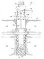
- FIG. 1is a cross-sectional view of an example well system 100 for managing cement in a subterranean zone.
- the system 100may include a cement slurry with devices that executes one or more operations associated with managing the setting of the cement slurry. Operations may include determining one or more parameters of the cement and/or cement slurry (e.g., moisture content, temperature, pH, ion concentration), releasing an activator that initiates or accelerates the setting process, and/or others.
- the system 100may periodically interrogate sensors in the cement to detect operating conditions over a period of time. For example, the system 100 may detect properties of cement to evaluate a status of, for example, an operating wellbore.
- the system 100may having an on-command cement delivery system that selectively controls setting of a cement slurry.
- the system 100may include a cement slurry with devices that release an activator into the cement slurry in response to at least an activation signal.
- An activatortypically includes any chemicals that activate and/or accelerate the setting process for a cement slurry in the system 100 .
- An activatormay also retard or otherwise effect the setting or properties of the cement slurry.
- the system 100may include one or more of the following activators: sodium hydroxide, sodium carbonate, calcium chloride, calcium nitrite, calcium nitrate, and/or others.
- the system 100may include devices with sensors and activators such that the devices release the activators in response to at least detecting predefined criteria in the cement slurry such as the pH reaching a specified threshold.
- the activation devicesmay include elements that substantially enclose one or more activators and that release the activator in response to at least an event.
- the activation devicesmay receive a signal (e.g., infrared signal), and in response to the signal, the enclosing element may release the one or more activators.
- the system 100may mechanically move the enclosing element, chemically remove at least a portion of the enclosing element, resistively heat the enclosing element to form an opening, and/or other processes for releasing the one or more activators.
- the system 100may include Micro-Electro-Mechanical System (MEMS) devices in the cement slurry that mechanically releases the activators.
- MEMSMicro-Electro-Mechanical System
- the system 100includes a cement slurry in an annulus formed between a casing and a wellbore, and when the cement is set, the cement secures the casing in place.
- the system 100may allow cement properties to be tailored once the cement slurry has been pumped down the borehole.
- the system 100may monitor the cement during normal operation conditions.
- the well system 100includes a production zone 102 , a non-production zone 104 , a wellbore 106 , a cement slurry 108 , and devices 110 .
- the production zone 102may be a subterranean formation including resources (e.g., oil, gas, water).
- the non-production zone 104may be one or more formations that are isolated from the wellbore 106 using the cement slurry 108 .
- the zone 104may include contaminants that, if mixed with the resources, may result in requiring additional processing of the resources and/or make production economically unviable.
- the cement slurry 108may be pumped or selectively positioned in the wellbore 106 .
- the properties of the cement slurry 108may be monitored using the devices 110 .
- the setting of the cement slurry 108may be activated or accelerated using the devices 110 .
- the devices 110may release an activator in response to a signal initiated by, for example, a user of the system 100 and/or the devices 110 detecting specified operating conditions.
- a usermay configure the system 100 without substantial interference from the setting of the cement slurry 108 .
- the wellbore 106extends from a surface 112 to the production zone 102 .
- the wellbore 106may include a rig 114 that is disposed proximate to the surface 112 .
- the rig 114may be coupled to a tubing string 116 that extends a substantial portion of the length of the wellbore 106 from about the surface 112 towards the production zones 102 (e.g., hydrocarbon-containing reservoir).
- the tubing string 116can extend past the production zone 102 .
- the tubing string 116may extend to proximate a terminus 118 of the wellbore 106 .
- the well 106may be completed with the tubing string 116 extending to a predetermined depth proximate to the production zone 102 .
- the wellbore 106initially extends in a substantially vertical direction toward the production zone 102 .
- the wellbore 106may include other portions that are horizontal, slanted or otherwise deviated from vertical.
- the rig 114may be centered over a subterranean oil or gas formation 102 located below the earth's surface 112 .
- the rig 114includes a work deck 124 that supports a derrick 126 .
- the derrick 126supports a hoisting apparatus 128 for raising and lowering pipe strings such as tubing string 116 .
- Pump 130is capable of pumping a variety of wellbore compositions (e.g., drilling fluid, cement) into the well and includes a pressure measurement device that provides a pressure reading at the pump discharge.
- the wellbore 106has been drilled through the various earth strata, including formation 102 .
- the tubing string 116is often placed in the wellbore 106 to facilitate the production of oil and gas from the formation 102 .
- the tubing string 116is a string of pipes that extends down wellbore 106 , through which oil and gas may be extracted.
- a cement or casing shoe 132is typically attached to the end of the casing string when the casing string is run into the wellbore. The casing shoe 132 guides the tubing string 116 toward the center of the hole and may minimize or otherwise decrease problems associated with hitting rock ledges or washouts in the wellbore 106 as the casing string is lowered into the well.
- the casing shoe 132may be a guide shoe or a float shoe, and typically comprises a tapered, often bullet-nosed piece of equipment found on the bottom of the casing string 116 .
- the casing shoe 132may be a float shoe fitted with an open bottom and a valve that serves to prevent reverse flow, or U-tubing, of cement slurry 108 from annulus 122 into tubing string 116 as tubing string 116 is run into wellbore 106 .
- the region between tubing string 116 and the wall of wellbore 106is known as the casing annulus 122 .
- tubing string 116is usually “cemented” in wellbore 106 , which is referred to as “primary cementing.”
- the cement slurry 108may be injected into the wellbore 106 through one or more perforations 134 .
- the cement slurry 108may flow through a hose 136 into the tubing string 116 .
- the tubing string 116may rest or otherwise abut a lip 138 of the surface casing 120 .
- the system 100may activate the setting of the cement slurry 108 using the activator devices 110 during, for example, conventional primary cementing operation.
- the devices 110may mixed into the cement slurry 108 prior to entering the tubing string 116 , and the cement slurry 108 may then be pumped down the inside of the tubing string 116 .
- the devices 110may be mixed in the cement slurry 108 at a density in the range of 4-24 pound per gallon (ppg). As the slurry 108 reaches the bottom of tubing string 116 , it flows out of tubing string 116 and into casing annulus 122 between tubing string 116 and the wall of wellbore 106 .
- a wellbore servicing fluide.g., drilling mud
- the wipercontacts the inside surface of tubing string 116 and pushes any remaining slurry 108 out of tubing string 116 .
- a signalmay be transmitted to the devices 110 before, during, and/or after the pumping is complete.
- the signalmay request detected operating conditions, initiate release of activators, and/or other operations.
- the devices 110may release activators that initiate and/or accelerating the setting of the cement slurry 108 in the annulus 122 in response to at least the signal.
- the tubing string 116may be affixed to the adjacent ground material with a cement jacket as illustrated in FIGS. 2A and 2B .
- the tubing string 116comprises a metal.
- the tubing string 116may be configured to carry a fluid, such as air, water, natural gas, or to carry an electrical line, tubular string, or other elements.
- a cement slurry 108 including devices 110may be pumped into annulus 122 by a pump truck (not illustrated).
- Example cement slurries 110are discussed in more detail below.
- the devices 110may release activators to activate or otherwise increase the setting rate of the cement slurry 108 in response to at least a signal.
- the devices 110may activate the cement slurry 108 to set cement in the annulus 122 .
- the devices 110may detect one or more attributes of the cement slurry 108 such as moisture content, temperature, pH, ion concentration, and/or other parameters.
- substantially all of the cement sets in the annulus 122 , and only a limited portion, if any, of the cemententers the interior of the tubing string 116 . In some implementations, all the cement sets in the annulus 122 , and no portion of the cement slurry 108 enters the interior of the tubing string 116 .
- the activation devices 110may release an activator that initiates or accelerates the setting of the cement slurry 108 .
- the cement slurry 108may remain in a substantially slurry state for a specified period of time, and the activation devices 110 may activate the cement slurry in response to at least a signal.
- the activation devices 110may receive a signal and, in response to the signal, release activators.
- the activation devices 110enclose the activations with, for example, a membrane.
- the membranemay be metal, a polymer, and/or other element.
- Suitable polymers for creating such a membraneinclude polystyrene, ethylene/vinyl acetate copolymer, polymethylmethacrylate polyurethanes, polylactic acid, polyglycolic acid, polyvinylalcohol, polyvinylacetate, hydrolyzed ethylene/vinyl acetate, silicones, and combinations or copolymers of each.
- the activation device 110may form an opening in the membrane.
- the activation device 110may form an opening by mechanically moving a portion of the membrane and/or by releasing a chemical that removes a portion of the membrane.
- the activation signalmay directly activate the membrane.
- the activation signalmay be an ultrasonic signal that vibrates the membrane to form an opening.
- the activation device 110may include a polymer membrane that ultrasonically degrades to release the enclosed activators.
- an ultrasonic signalmay structural change the membrane to release the activators such as, for example, opening the membrane as a flap.
- the signalincludes at least one of an electromagnetic signal, a pressure signal, a magnetic signal, an electric signal, an acoustic signal, an ultrasonic signal, or a radiation signal, and wherein the radiation signal comprises at least one of neutrons, alpha particles, or beta particles.
- the cement compositionmay sets in a range from one hour to one day after reacting with the activator.
- the activation devicemay includes at least one dimension in a range from about 1 ⁇ m to about 10,000 ⁇ m.
- the release activatormay include sodium hydroxide, sodium carbonate, amine compounds, salts comprising calcium, sodium, magnesium, aluminum, and/or a mixture thereof.
- the activation device 110may release a calcium salt such as calcium chloride.
- the activation device 110may release a sodium salt such as sodium chloride, sodium aluminate, and/or sodium silicate.
- the activation device 110may release a magnesium salt such as magnesium chloride.
- the activation device 110may release amine compounds such as triethanol amine, tripropanol amine, tri-isopropanol amine, and/or diethanol amine.
- the activation device 110may release the activator in a sufficient amount to set the cement slurry 108 within about 1 minute to about 2 hours. Alternatively, the activator may be present in a sufficient amount to set the slurry within about an hour to about a day.
- the concentrationmay be in the range of from about 3% to about 15% by weight of the cement in the cement slurry 108 .
- the concentrationmay be in the range of from about 0.5% to about 5% by weight of the cement in the cement slurry 108 .
- the activation device 110may “flash-set” the cement slurry 108 .
- flash-setwill be understood to mean the initiation of setting of the cement slurry 108 within about 1 minute to about 5 minutes after contacting the released activator.
- the previously identified activatorsmay flash set the cement slurry 108 .
- Flash-set activatorsmay include sodium hydroxide, sodium carbonate, potassium carbonate, bicarbonate salts of sodium or potassium, sodium silicate salts, sodium aluminate salts, ferrous and ferric salts (e.g., ferric chloride and ferric sulfate), polyacrylic acid salts, and/or others.
- the following activatorscan flash-set the cement slurry 108 based on these activators exceeding a specified concentration: calcium nitrate, calcium acetate, calcium chloride, and/or calcium nitrite.
- the activation device 110may release a solid activator.
- the devices 110comprise MEMS devices containing an array of microreservoirs lined with an ultrasound sensitive polymer (e.g., polyanhydrides, polyglycolides, polylactides, ethylene vinyl acetate copolymers, silicones) membranes.
- the microreservoirsmay be loaded with one or multiple cement additives (e.g., accelerator, retarder).
- acoustic wavese.g., ultrasonic waves
- the polymer membranemay begin to degrade/breakdown and cause the release of the desired additives. Release rate of the additives may be controlled by the intensity of the ultrasound and its duration.
- a MEMS devicebe fabricated to have microreservoirs but may include micropumps as well.
- the desired additivemay be dispersed the pumps.
- MEMS device 110may have an acoustic/ultrasonic sensor/transducer/detector that once to ultrasound, the additive may be pumped via cavitation.
- the MEMS triggermay cause a cascade of events (e.g., temperature increase and/or pressure) resulting in the release of the additives.
- the sensorsmay be positioned within the wellbore 106 .
- the sensors 110may extend along all or a portion of the length of the wellbore 106 adjacent the tubing string 116 .
- the sealant slurry 108may be placed downhole as part of a primary cementing, secondary cementing, or other sealant operation as described in more detail herein.
- a data interrogator toolcan be positioned in an operable location to gather data from the sensors 110 , for example lowered within the wellbore 106 proximate the sensors 110 .
- the data interrogator toolmay interrogate the data sensors 110 (e.g., by sending out an RF signal) while the data interrogator tool traverses all or a portion of the wellbore 106 containing the sensors 110 .
- the data sensors 110may be activated to record and/or transmit data the signal from the data interrogator tool.
- the data interrogator toolmay communicate the data to one or more computer components (e.g., memory and/or microprocessor) that may be located within the tool, at the surface 112 , or both.
- the datamay be used locally or remotely from the tool to calculate the location of each data sensor and correlate the measured parameter(s) to such locations to evaluate sealant performance.
- the sensors 110include MEMS sensors that, for example, detect conditions during drilling (e.g., drilling fluid comprising MEMS sensors) or during cementing (e.g., cement slurry 108 comprising MEMS sensors) as described in more detail below. Additionally or alternatively, data gathering may be carried out at one or more times subsequent to the initial placement in the composition 108 comprising MEMS sensors 110 . For example, data gathering may be carried out at the time of initial placement in the well of the composition 108 comprising MEMS sensors 110 or shortly thereafter to provide a baseline data set. As the well is operated for recovery of natural resources over a period of time, data gathering may be performed additional times, for example at regular maintenance intervals such as every 1 year, 5 years, or 10 years.
- the data recovered during subsequent monitoring intervalscan be compared to the baseline data as well as any other data obtained from previous monitoring intervals, and such comparisons may indicate the overall condition of the wellbore 106 .
- changes in one or more sensed parametersmay indicate one or more problems in the wellbore.
- consistency or uniformity in sensed parametersmay indicate no substantive problems in the wellbore 106 .
- data (e.g., sealant parameters) from a plurality of monitoring intervalsis plotted over a period of time, and a resultant graph may be provided showing an operating or trend line for the sensed parameters.
- Atypical changes in the graph as indicated for example by a sharp change in slope or a step change on the graphmay provide an indication of one or more present problems or the potential for a future problem. Accordingly, remedial and/or preventive treatments or services may be applied to the wellbore 106 to address present or potential problems.
- the MEMS sensors 110can be contained within a sealant composition 108 placed substantially within the annular space 122 between a tubing string and the wellbore wall. That is, substantially all of the MEMS sensors 110 may be located within or in close proximity to the annular space 122 . In some implementations, the wellbore servicing fluid comprising the MEMS sensors 110 (and thus likewise the MEMS sensors 110 ) may not substantially penetrate, migrate, or travel into the formation from the wellbore 106 . In an alternative embodiment, substantially all of the MEMS sensors 110 are located within, adjacent to, or in close proximity to the wellbore 106 , for example less than or equal to about 1 foot, 3 feet, 5 feet, or 10 feet from the wellbore 106 .
- Such adjacent or close proximity positioning of the MEMS sensors 110 with respect to the wellbore 106may be in contrast to placing MEMS sensors 110 in a fluid that is pumped into the formation 102 in large volumes and substantially penetrates, migrates, or travels into or through the formation 102 , for example as occurs with a fracturing fluid or a flooding fluid.
- the MEMS sensors 110may be placed proximate or adjacent to the wellbore 106 (in contrast to the formation at large), and provide information relevant to the wellbore itself and compositions (e.g., sealants 108 ) used therein (again in contrast to the formation or a producing zone at large).
- the data sensors 110 added to the sealant slurry 108can be passive sensors that do not require continuous power from a battery or an external source in order to transmit real-time data.
- the data sensors 110are micro-electromechanical systems (MEMS) comprising one or more (and typically a plurality of) MEMS devices, referred to herein as MEMS sensors 110 .
- MEMS devices 110are well known, e.g., a semiconductor device with mechanical features on the micrometer scale.
- MEMSembody the integration of mechanical elements, sensors, actuators, and electronics on a common substrate.
- the substratecomprises silicon.
- MEMS elementsinclude mechanical elements which are movable by an input energy (electrical energy or other type of energy).
- a sensor 110may be designed to emit a detectable signal based on a number of physical phenomena, including thermal, biological, optical, chemical, and magnetic effects or stimulation.
- MEMS devices 110are minute in size, have low power requirements, are relatively inexpensive and are rugged, and thus are well suited for use in wellbore servicing operations.
- the data sensors 110comprise an active material connected to (e.g., mounted within or mounted on the surface of) an enclosure, the active material being liable to respond to a wellbore parameter, and the active material being operably connected to (e.g., in physical contact with, surrounding, or coating) a capacitive MEMS element.
- the MEMS sensors 110sense one or more parameters within the wellbore 106 .
- the parametermay include temperature, pH, moisture content, ion concentration (e.g., chloride, sodium, and/or potassium ions), and/or others.
- the MEMS sensors 110may also sense well cement characteristic data such as stress, strain, or combinations thereof.
- the MEMS sensors 110 of the present disclosuremay comprise active materials that respond to two or more measurands. In such a way, two or more parameters may be monitored.
- Suitable active materialssuch as dielectric materials, that respond in a predictable and stable manner to changes in parameters over a long period may be identified according to methods well known in the art, for example see, e.g., Ong, Zeng and Grimes. “A Wireless, Passive Carbon Nanotube-based Gas Sensor,” IEEE Sensors Journal, 2, 2, (2002) 82-88; Ong, Grimes, Robbins and Singl, “Design and application of a wireless, passive, resonant-circuit environmental monitoring sensor,” Sensors and Actuators A, 93 (2001) 33-43, each of which is incorporated by reference herein in its entirety.
- MEMS sensors 110 suitable for the methods of the present disclosure that respond to various wellbore parametersare disclosed in U.S. Pat. No. 7,038,470 B1 that is incorporated herein by reference in its entirety.
- the MEMS sensors 110can be coupled with radio frequency identification devices (RFIDs) and can detect and transmit parameters and/or well cement characteristic data for monitoring the cement during its service life.
- RFIDscombine a microchip with an antenna (the RFID chip and the antenna are collectively referred to as the “transponder” or the “tag”).
- the antennaprovides the RFID chip with power when exposed to a narrow band, high frequency electromagnetic field from a transceiver.
- a dipole antenna or a coil, depending on the operating frequency, connected to the RFID chippowers the transponder when current is induced in the antenna by an RF signal from the transceiver's antenna.
- Such a devicemay return a unique identification “ID” number by modulating and re-radiating the radio frequency (RF) wave.
- RFradio frequency
- the MEMS sensor and RFID tagare preferably integrated into a single component 110 (e.g., chip or substrate), or may alternatively be separate components 110 operably coupled to each other.
- an integrated, passive MEMS/RFID sensor 110can contain a data sensing component, an optional memory, and an RFID antenna, whereby excitation energy is received and powers up the sensor, thereby sensing a present condition and/or accessing one or more stored sensed conditions from memory and transmitting same via the RFID antenna.
- the data sensors 110may form a network using wireless links to neighboring data sensors and have location and positioning capability through, for example, local positioning algorithms as are known in the art.
- the sensors 110may organize themselves into a network by listening to one another, therefore allowing communication of signals from the farthest sensors towards the sensors closest to the interrogator to allow uninterrupted transmission and capture of data.
- the interrogator toolmay not need to traverse the entire section of the wellbore containing MEMS sensors in order to read data gathered by such sensors. For example, the interrogator tool may only need to be lowered about half-way along the vertical length of the wellbore containing MEMS sensors.
- the interrogator toolmay be lowered vertically within the wellbore to a location adjacent to a horizontal arm of a well 106 , whereby MEMS sensors 110 may be located in the horizontal arm may be read without the need for the interrogator tool to traverse the horizontal arm.
- the interrogator toolmay be used at or near the surface and read the data gathered by the sensors distributed along all or a portion of the wellbore.
- sensors 110may be located distal to the interrogator may communicate via a network formed by the sensors as described previously.
- the MEMS sensors 110are ultra-small, e.g., 1 mm 2 , such that they are pumpable in a sealant slurry.
- the MEMS device 110can be approximately 1 ⁇ m 2 to 1 mm 2 , 1 mm 2 to 3 mm 2 , 3 mm 2 to 5 mm 2 , 5 mm 2 to 100 mm 2 , and/or other dimensions.
- the data sensors 110may be capable of providing data throughout the cement service life. In implementations, the data sensors 110 can provide data for up to 100 years.
- the wellbore composition 108may comprise an amount of MEMS effective to measure one or more desired parameters.
- the wellbore composition 108may comprises an effective amount of MEMS such that sensed readings may be obtained at intervals of about 1 foot, 6 inches, 1 inch, and/or other interval along the portion of the wellbore 106 containing the MEMS 110 .
- the MEMSmay be present in the wellbore composition 108 in an amount of from about 0.01 to about 50 weight percent.
- the MEMS sensors 110may comprise passive (remain unpowered when not being interrogated) sensors energized by energy radiated from a data interrogator tool.
- the data interrogator toolmay comprise an energy transceiver sending energy (e.g., radio waves) to and receiving signals from the MEMS sensors 110 and a processor processing the received signals.
- the data interrogator toolmay further comprise a memory component, a communications component, or both.
- the memory componentmay store raw and/or processed data received from the MEMS sensors 110
- the communications componentmay transmit raw data to the processor and/or transmit processed data to another receiver, for example located at the surface.
- the tool componentse.g., transceiver, processor, memory component, and communications component
- one or more of the data interrogator (not illustrated) componentsmay be integrated into a tool or unit that is temporarily or permanently placed downhole (e.g., a downhole module).
- a removable downhole modulecomprises a transceiver and a memory component, and the downhole module is placed into the wellbore, reads data from the MEMS sensors, stores the data in the memory component, is removed from the wellbore, and the raw data is accessed.
- the removable downhole modulemay have a processor to process and store data in the memory component, which is subsequently accessed at the surface when the tool is removed from the wellbore.
- the removable downhole modulemay have a communications component to transmit raw data to a processor and/or transmit processed data to another receiver, for example located at the surface.
- the communications componentmay communicate via wired or wireless communications.
- the downhole componentmay communicate with a component or other node on the surface via a cable or other communications/telemetry device such as a radio frequency, electromagnetic telemetry device or an acoustic telemetry device.
- the removable downhole componentmay be intermittently positioned downhole via any suitable conveyance, for example wire-line, coiled tubing, straight tubing, gravity, pumping, etc., to monitor conditions at various times during the life of the well.
- the data interrogator toolcomprises a permanent or semi-permanent downhole component that remains downhole for extended periods of time.
- a semi-permanent downhole modulemay be retrieved and data downloaded once every few years.
- a permanent downhole modulemay remain in the well throughout the service life of well.
- a permanent or semi-permanent downhole modulecomprises a transceiver and a memory component, and the downhole module is placed into the wellbore, reads data from the MEMS sensors, optionally stores the data in the memory component, and transmits the read and optionally stored data to the surface.
- the permanent or semi-permanent downhole modulemay have a processor to process and sensed data into processed data, which may be stored in memory and/or transmit to the surface.
- the permanent or semi-permanent downhole modulemay have a communications component to transmit raw data to a processor and/or transmit processed data to another receiver, for example located at the surface.
- the communications componentmay communicate via wired or wireless communications.
- the downhole componentmay communicate with a component or other node on the surface via a cable or other communications/telemetry device such as an radio frequency, electromagnetic telemetry device or an acoustic telemetry device.
- the data interrogator toolcomprises an RF energy source incorporated into its internal circuitry and the data sensors are passively energized using an RF antenna, which picks up energy from the RF energy source.
- the data interrogator toolmay be integrated with an RF transceiver.
- the MEMS sensorse.g., MEMS/RFID sensors
- the RF transceiverare empowered and interrogated by the RF transceiver from a distance, for example a distance of greater than 10 m, or alternatively from the surface or from an adjacent offset well.
- the data interrogator tooltraverses within a casing in the well and reads MEMS sensors located in a sealant (e.g., cement) sheath surrounding the casing and located in the annular space between the casing and the wellbore wall.
- the interrogatorsenses the MEMS sensors when in close proximity with the sensors, typically via traversing a removable downhole component along a length of the wellbore comprising the MEMS sensors.
- close proximitycomprises a radial distance from a point within the casing to a planar point within an annular space between the casing and the wellbore.
- close proximitycomprises a distance of 0.1 m to 1 m, 1 m to 5 m, 5 m to 10 m, or other ranges.
- the transceiverinterrogates the sensor with RF energy at 125 kHz and close proximity comprises 0.1 m to 0.25 m.
- the transceiverinterrogates the sensor with RF energy at 13.5 MHz and close proximity comprises 0.25 m to 0.5 m.
- the transceiverinterrogates the sensor with RF energy at 915 MHz and close proximity comprises 0.5 m to 1 m.
- the transceiverinterrogates the sensor with RF energy at 2.4 GHz and close proximity comprises 1 m to 2 m.
- the slurry 108may include cementitious and/or non-cementitious sealants without departing from the scope of this disclosure.
- non-cementitious sealantscomprise resin based systems, latex based systems, or combinations thereof.
- the sealantcomprises a cement slurry with styrene-butadiene latex (e.g., as disclosed in U.S. Pat. No. 5,588,488 incorporated by reference herein in its entirety). Sealants may be utilized in setting expandable casing, which is further described hereinbelow.
- the sealantcan be a cement utilized for primary or secondary wellbore cementing operations, as discussed further hereinbelow.
- the sealant 108can be cementitious and comprises a hydraulic cement that sets and hardens by reaction with water.
- hydraulic cementsinclude but are not limited to Portland cements (e.g., classes A, B, C, G, and H Portland cements), pozzolana cements, gypsum cements, phosphate cements, high alumina content cements, silica cements, high alkalinity cements, shale cements, acid/base cements, magnesia cements, fly ash cement, zeolite cement systems, cement kiln dust cement systems, slag cements, micro-fine cement, metakaolin, and combinations thereof.
- sealantsare disclosed in U.S. Pat. Nos.
- the sealant 108may comprise a sorel cement composition, which typically comprises magnesium oxide and a chloride or phosphate salt which together form for example magnesium oxychloride.
- a sorel cement compositiontypically comprises magnesium oxide and a chloride or phosphate salt which together form for example magnesium oxychloride.
- magnesium oxychloride sealantsare disclosed in U.S. Pat. Nos. 6,664,215 and 7,044,222, each of which is incorporated herein by reference in its entirety.
- the wellbore composition 108may include a sufficient amount of water to form a pumpable slurry.
- the watermay be fresh water or salt water (e.g., an unsaturated aqueous salt solution or a saturated aqueous salt solution such as brine or seawater).
- the cement slurry 108may be a lightweight cement slurry containing foam (e.g., foamed cement) and/or hollow beads/microspheres.
- the MEMS sensors 110can be incorporated into or attached to all or a portion of the hollow microspheres. Thus, the MEMS sensors 110 may be dispersed within the cement along with the microspheres. Examples of sealants containing microspheres are disclosed in U.S. Pat.
- the MEMS sensors 110are incorporated into a foamed cement such as those described in more detail in U.S. Pat. Nos. 6,063,738; 6,367,550; 6,547,871; and 7,174,962, each of which is incorporated by reference herein in its entirety.
- additivesmay be included in the cement composition for improving or changing the properties thereof.
- additivesinclude but are not limited to accelerators, set retarders, defoamers, fluid loss agents, weighting materials, dispersants, density-reducing agents, formation conditioning agents, lost circulation materials, thixotropic agents, suspension aids, or combinations thereof.
- Other mechanical property modifying additivesfor example, fibers, polymers, resins, latexes, and the like can be added to further modify the mechanical properties. These additives may be included singularly or in combination. Methods for introducing these additives and their effective amounts are known to one of ordinary skill in the art.
- the cement slurry 108may comprise a “delayed set” cement compositions that remain in a slurry state (e.g., resistant to gelatinizing) for an extended period of time.
- a delay-set cement slurry 108may include a cement, a base fluid, and a set retarder.
- activationmay change the state of the cement slurry from delay set to neutral, to accelerated, or to less delayed.
- the cement slurry 108may include other additives.
- the delayed-set cement slurry 108typically remains in a slurry state for in range of about 6 hours to about 7 days under downhole or other conditions.
- the cement slurry 108may include components that result in a slurry state for a greater, or shorter, amount of time.
- the cement slurry 108may be mixed or otherwise made well ahead of positioning the slurry 108 in the annulus 122 .
- the delayed-set cement slurry 108can, in some implementations, include a cement, a base fluid, and a set retarder.
- the delayed-set cement slurry 108may be set at a desired time, such as after placement, by activating the activation devices 110 to release one or more activators.
- delayed-set cement slurry 108may include a hydraulic cement.
- hydraulic cementstypically include calcium, aluminum, silicon, oxygen, and/or sulfur and may set and harden by reaction with water.
- Hydraulic cementsinclude, but are not limited to, Portland cements, pozzolanic cements, high aluminate cements, gypsum cements, silica cements, and high alkalinity cements.
- the delayed-set cement slurry 108may include cements based on shale or blast furnace slag. In these instances, the shale may include vitrified shale, raw shale (e.g., unfired shale), and/or a mixture of raw shale and vitrified shale.
- the delayed-set cement slurry 108may include one or more base fluids such as, for example, an aqueous-based base fluid, a nonaqueous-based base fluid, or mixtures thereof.
- Aqueous-basedmay include water from any source that does not contain an excess of compounds (e.g., dissolved organics, such as tannins) that may adversely affect other compounds in the cement slurry 108 .
- the delayed-set cement slurry 108may include fresh water, salt water (e.g., water containing one or more salts), brine (e.g., saturated salt water), and/or seawater.
- Nonaqueous-basedmay include one or more organic liquids such as, for example, mineral oils, synthetic oils, esters, and/or others.
- any organic liquid in which a water solution of salts can be emulsifiedmay be suitable for use as a base fluid in the delayed-set cement slurry 108 .
- the base fluidexceeds a concentration sufficient to form a pumpable slurry.
- the base fluidmay be water in an amount in the range of from about 25% to about 150% by weight of cement (“bwoc”) such as one or more of the following ranges: about 30% to about 75% bwoc; about 35% to about 50% bwoc; about 38% to about 46% bwoc; and/or others.
- the cement slurry 108may include one or more different types of set retarders such as, for example, phosphonic acid, phosphonic acid derivatives, lignosulfonates, salts, organic acids, carboxymethylated hydroxyethylated celluloses, synthetic co- or ter-polymers comprising sulfonate and carboxylic acid groups, and/or borate compounds.
- the set retarders used in the present inventionare phosphonic acid derivatives. Examples of set retarders may include phosphonic acid derivatives commercially available from, for example, Solutia Corporation of St. Louis, Mo.
- Example borate compoundsmay include sodium tetraborate, potassium pentaborate, and/or others.
- a commercially available example of a suitable set retarder comprising potassium pentaborateis available from Halliburton Energy Services, Inc. under the trade name “Component R.”
- Example organic acidsmay include gluconic acid, tartaric acid, and/or others.
- An example of a suitable organic acidmay be commercially available from Halliburton Energy Services, Inc. under the trade name “HR® 25.”
- Other examples of set retardersmay be commercially available from Halliburton Energy Services, Inc.
- the set retarder in the delayed-set cement slurry 108may be in an amount sufficient to delay the setting in a subterranean formation for a specified time.
- the amount of the set retarder included in the cement slurry 108may be in one or more of the following ranges: about 0.1% to about 10% bwoc; about 0.5% to about 4% bwoc; and/or others.
- the cement slurry 108may not include a set retarder.
- the system slurry 108may include high aluminate cements and/or phosphate cements independent of a set retarder.
- the activatorsmay initiate setting of the slurry 108 .
- these activatorsmay include alkali metal phosphate salts.
- High aluminate cementmay comprise calcium aluminate in an amount in the range of from about 15% to about 45% by weight of the high aluminate cement, Class F fly ash in an amount in the range of from about 25% to about 45% by weight of the high aluminate cement, and sodium polyphosphate in an amount in the range of from about 5% to about 15% by weight of the high aluminate cement.
- a reactive component of the cement compositione.g., the alkali metal phosphate salt
- the alkali metal phosphate saltmay be used as an activator.
- FIGS. 2A and 2Billustrate a cross sectional view of the well system 100 including set cement 202 in at least a portion of the annulus 122 .
- the activation devices 110released activators in at least a portion of the cement slurry 108 to form the set cement 202 .
- the cement slurry 108flowed into the annulus 122 through the tubing string 116 , and in response to at least a signal, the activation devices 110 in the slurry 108 released an activator.
- substantially all devices 110 in the annulus 122released activators to form the set cement 202 along substantially the entire length of the annulus 122 . Referring to FIG.
- the cement slurry 108flowed into the annulus 122 through the tubing string 116 , and in response to at least a signal, the activation devices 110 in the slurry 108 released activators within a specified location 204 .
- the region or location 204is located proximate the zone 102 .
- the activation devices 110 proximate the zone 102may release activators and form the set cement 202 located in the region 204 .
- the activation signalmay be localized to the region identified by 204 , and in response to at least the localized signal, the set cement 204 forms.
- an initial amount of the cement slurry 108may be exposed to an activation signal such that the setting period may be substantially equal to a period of time for the setting cement slurry 108 to flow to the location 204 .
- the cement slurry 108may be exposed to the activation signal as the slurry 108 including the devices 110 enters the tubing string 116 .
- fluid flow through the annulus 122may become more restricted and may eventually ceases.
- the cement slurry 108may be substantially prevented from flowing onto the surface 112 through the annulus 122 .
- the remainder of the cement slurry 108may set in the annulus 122 behind the leading edge as illustrated in FIG. 2A or the cement slurry 108 may set at a later time as illustrated in FIG. 2B . In the later, the remaining cement slurry 108 may be exposed to activation signals at a later time to initiate or accelerate the setting processes.
- FIG. 3illustrates an example activator device 110 of FIG. 1 in accordance with some implementations of the present disclosure.
- the activator device 110releases one or more stored activators in response to at least a wireless signal.
- the illustrated device 110is for example purposes only, and the device 110 may include some, none, or all of the illustrated elements without departing from the scope of this disclosure.
- the activator device 110includes a substrate 302 and a passivation layer 304 formed on the substrate 302 .
- the passivation layer 304includes or is otherwise adjacent an activator module 306 for releasing activators, a transducer 308 for receiving wireless signals, logic 310 for controlling the activator module 306 , and a power module 312 for supplying power to the device 110 .
- the substrate 302may provide a mechanical structure to support the device elements and/or a surface for routing electrical and/or fluidic signals.
- the substrate 302may be silicon, quartz, glass, organic (e.g., kapton tape or other flexible material), FR-4, duroid, and/or other materials.
- the passivation layer 304can protect one or more modules from the surrounding cement slurry 108 and/or may provide direct access to the cement slurry 108 to, for example, release the activators.
- the activator module 306may release one or more activators to initiate or accelerate the setting of the cement slurry 108 .
- the activator module 306may receive one or more signals from the logic 310 and execute a process to initiate a reaction with, for example, the cement slurry 108 .
- the activator module 306may include a membrane or other element that encloses the activators. In these examples, the activator module 306 may move, remove, or otherwise open the element to release the activators into the cement slurry 108 .
- the activator module 306may include a heating element in the enclosing element that encloses a unitary chemical, a binary chemical set with a rupture membrane, unitary chemical with a rupture membrane, and/or other configures that release enclosed activators.
- the transducer 308may convert external stimulus into one or more transduction signals that are processed by the logic 310 .
- the transducer 308may detect signals such as ultrasonic, pressure, magnetic, electric, electromagnetic (e.g., RF, infrared, x-rays), acoustic, optical, VCF, nuclear (e.g., gamma, alpha, beta, neutron), and/or other signals.
- the logic 310may generate voltages for operating the activator module 306 using the power module 312 and in response to at least the transducer signal. For example, the logic 310 may dynamically switch between a “go” and a “no go” state in response to at least the transducer signals. In some implementations, the logic 310 may execute one or more of the following: receive power from the power module 312 ; receive one or more transducer signals from the transducer 308 ; generate one or more signals for the activator module 306 using the received power; transmit one or more signals to the activator module 306 to activate the release of one or more activators; and/or other processes.
- the logic 310may be complementary metal-oxide-semiconductor (CMOS), Transistor-transistor logic (TTL), bipolar, Radio Frequency (RF), and/or other type of device.
- CMOScomplementary metal-oxide-semiconductor
- TTLTransistor-transistor logic
- RFRadio Frequency
- the power module 312provides power to the device 110 .
- the power module 312may be a voltage generator that provides sufficient current to operate the logic 310 .
- the power module 312may be a battery in thin and/or thick film, components of a battery, one or more capacitors, one or more induction pick-up coils, and/or other elements that store power.
- FIGS. 4A-Cillustrate example implementations of the activator devices 110 releasing one or more activators.
- the device 110may comprise an acoustic trigger MEMS for controlled delivery of on command additives into a cement slurry.
- the devices 110may enable cement properties to be tailored once the cement slurry has been pumped downhole (e.g., retarded, accelerated in situ).
- the devices 110may release activators by moving one or more elements, resistively heating one or more elements to form at least one opening, chemically etching away one or more elements, and/or other processes.
- each device 110may re-transmit the activation signals to other devices 110 .
- the following implementationsare for illustration purposes only, and the devices 110 may release activators using some, all or none of these processes.
- the activator device 110mechanically moves the element 402 to release the activators 404 .
- the device 110may include a MEM device that encloses the activators 404 when the element 402 is in a first position.
- the element 402may rotate about an axis to a second position that releases the activators 404 into the cement slurry 108 .
- the activation signalmay directly move the element 402 .
- the activation signalmay structurally change the form of the element 402 through, for example, an ultrasonic signal.
- the device 110may switch the element 402 between the two positions at a specified frequency to assist or otherwise increase the dispersion rate of the activators 404 into the cement slurry 108 .
- the activator device 110resistively heats the element 402 to form an opening that releases the activators 404 .
- the element 402may be a gold membrane including a tungsten filament that generates heat from an applied current. In these instances, the generated heat may melt or otherwise deform the membrane to form an opening that releases the activators 404 .
- the element 402may be other materials such as a polymer. Referring to FIG.
- the device 110includes the activators 404 and release chemicals 406 that remove at least a portion of the element 402 to release the activators.
- the device 110includes a first reservoir 412 enclosing the activators 404 and a second reservoir 414 enclosing the release chemicals 406 using a retaining element 410 .
- the first reservoir 412 and the second reservoir 414may be configured to fluidly communicate case through the valve system 408 .
- the valve system 408may be substantially prevent the flow of the release chemicals 406 into the first reservoir 412 .
- the release chemicals 406may flow from the second reservoir 414 to the first reservoir 412 through the valve system 408 .
- the release chemicals 406reacts with the element 402 to form an opening that releases the activators 404 into the cement slurry 108 .
- the release chemicals 406may etch or otherwise dissolve the element 402 .
- FIGS. 5 and 6are flow diagrams illustrating example methods 500 and 600 for implementing and manufacturing devices including one or more activators.
- the illustrated methodsare described with respect to well system 100 of FIG. 1 , but these methods could be used by any other system.
- well system 100may use any other techniques for performing these tasks. Thus, many of the steps in these flowcharts may take place simultaneously and/or in different order than as shown.
- the well system 100may also use methods with additional steps, fewer steps, and/or different steps, so long as the methods remain appropriate.
- method 500begins at step 502 where activation devices are selected based, at least in part, on one or more parameters.
- the activation devices 110 and the enclosed activatorsmay be based, at least in part, on components of the cement slurry 108 .
- the activation devices 110may be selected based on downhole conditions (e.g., temperature).
- the selected activation devicesare mixed with a cement slurry.
- the activation devices 110may be mixed with the cement slurry 108 as the truck 130 pumps the slurry into the annulus 122 .
- the activation devices 110may be mixed with dry cement prior to generating the cement slurry 108 .
- the cement slurry including the activation devicesare pumped downhole.
- the cement slurry 108 including the activation devices 110may be pumped into the annulus 122 at a specified rate.
- One or more activation signalsare transmitted to the at least a portion of the downhole cement slurry at step 508 .
- the transmittermay be lowered into the casing to transmit signals at a portion of the cement slurry 108 .
- the transmitted signalsmay activate the devices 110 proximate the shoe 140 to set that portion of the cement slurry 108 as illustrated in FIG. 2B .
- the tubing string 116may be moved (e.g., up/down) to assist in distributing the activators as desired.
- the method 600begins at step 602 where a substrate with a passivation layer is identified.
- the substrate 302 including the passivation layer 304 of FIG. 3may be identified.
- the power, transducer, and logic modules and at least a portion of the activation moduleare fabricated.
- a reservoir in the activation moduleis also fabricated.
- the transducer 308 , the logic 310 , the power module 312 , and at least a portion of the activation module 306is fabricated.
- a reservoir for enclosing at least a portion of the activatorssuch as the reservoirs illustrated in FIGS. 4A-C .
- activatorsare deposited in the reservoir.
- the activators 404may be deposited in the reservoirs illustrated in FIGS. 4A-C .
- a membraneis fabricated over the reservoir to substantially enclose the activators.
- the element 402may be fabricated to enclose the activators 404 in the reservoir.
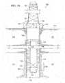
- FIG. 7illustrates an example well system 100 in connection with transmitting activation signals to the cement slurry 122 .
- the system 100may wireless transmit electromagnetic signals to the cement slurry 108 including a request to release activators in the cement slurry 108 .
- the system 100includes an interior medium 702 and a signal source 706 connected to the interior medium 702 and the tubing string 116 through the connections 708 a and 708 b , respectively.
- the connections 708may be ohmic contacts, capacitively coupled, and/or others.
- the tubing string 116may be a “hot patch” for signals.
- the tubing string 116may be a continuous metal path or a metal path with a finite number of discontinuities. In the later, each portion may result in a modest step attenuation.
- the interior medium 702may be at least partially enclosed in one or more shells or interior pipe 704 .
- the system 100may enable signal transduction down a long pipe using leaky feeder principles (LP-LF).
- the system 100may transducer a signal using one or more of the following: the tubing string 116 ; the surface casing 124 ; and/or one or more interior pipes 704 .
- the surface tubing string 116may have a length of 100 m or greater.
- the interior pipe 704may have a length of 100 m or less.
- the interior medium 702may be metal, air, and/or a liquid.
- the surface tubing string 116 and/or the interior pipe 704may be used as an additional hot path that is out of phase with the casing signal and/or a different signaling waveform.
- the signal source 706can be any hardware, software and/or firmware that generates an electrical signal.
- a connection between the signal source 706 and the tubing string 116may include return paths through one or more of the following: the cement slurry 108 ; the surface casing 120 ; the non-production zone 104 ; the interior medium 702 ; shells of the pipe 704 ; and/or others.
- the cement slurry 108may be very basic (e.g., pH 13) and a loss medium that attenuates the return signal.
- the signal source 706may produce time-varying voltages that are propagated down conduits such as the tubing string 116 .
- the signal source 706may propagate one or more of the following frequencies: Ultra Low Frequency (ULF) such as 0.1 Hz to 10 Hz; Very low frequency (VLF) such as 10 Hz to 30 kHz; Low Frequency (LF) such as 30 kHz to 30 MHz; High Frequency (HF) such as 3 MHz to 30 MHz; Very High Frequency (VHF) such as 30 MHz to 300 MHz; and/or Ultra High Frequency (UHF) such as greater than 300 MHz.
- the signal source 706may directly drives the tubing string 116 and drive the surface casing 120 180° out of phase.
- the interior pipe 704may not be driven and the connections 706 may be capacitively coupled.
- FIGS. 8A and 8Billustrated an example power module 312 of FIG. 3 in accordance with some implementations of the present disclosure.
- the power module 312can use an alkaline or acidic environment generated by, for example, the cement slurry 108 .
- the power module 312may generate a voltage difference using the cement slurry 108 and independent of storing power using, for example, a battery or capacitor.
- the power module 312may be fabricated using thin and/or thick film photolithography techniques to create sub-millimeter (sub-mm) scale batteries.
- the example power module 312is for illustration purposes only, and the module 312 may include some, all or none of the illustrated elements without departing from the scope of this disclosure.
- the illustrated power module 312includes a first metallic element 802 and a second metallic element 804 that form the terminals of the power module 312 .
- the first metallic element 802 and the second metallic element 804react with the surrounding cement slurry 108 to generate a voltage different between the two terminals.
- the first metallic element 802 and the second metallic element 804are at least partially enclosed by the passivation layer 304 and the substrate 302 .
- the substrate 302may comprise silicon, glass, sapphire, organic flexible material, and/or other materials.
- the passivation layer 304includes a first aperture 806 a that exposes at least a surface or portion of the first metallic element 802 and a second aperture 806 b that exposes at least a surface or portion of the second metallic element 804 .
- a voltage differenceis generated between these terminals.
- this voltage differencesupplies power to the load 808 such as the logic 310 .
- the terminalare connected to the load 808 through the leads 810 a and 810 b .
- the apertures 806 a and 806 bmay be formed, for example, by photolithography or a thick film printing process.
- the substrate 302may be silicon and about 1 mm by 1 mm by 100 ⁇ m, and the cement slurry 108 may be in a pre-cured wet state.
- the first metallic element 802may be a metal such as zinc
- the second metallic element 804may be a metallic salt such as manganese dioxide.
- the elements 802 and 804may be deposited using thick film screening printing and may be each about 150 ⁇ m by 150 ⁇ m by 50 ⁇ m.
- the apertures 806 a and 806 bmay be 100 ⁇ m by 100 ⁇ m
- the layer 304may be photoimageable BCB.
- the leads or connections 810 a and 810 bmay be thin film metallizations.
- FIGS. 9-11methods for detecting and/or monitoring the position and/or condition of wellbore compositions are illustrated such as, for example, sealant conditions (e.g., cement) using MEMS-based data sensors 110 , previously discussed with respect to FIG. 1 . Still more particularly, the present disclosure describes methods of monitoring the integrity and performance of wellbore compositions over the life of the well using MEMS-based data sensors. Performance may be indicated by changes, for example, in various parameters, including, but not limited to, moisture content, temperature, pH, and various ion concentrations (e.g., sodium, chloride, and potassium ions) of the cement.
- sealant conditionse.g., cement
- MEMS-based data sensors 110previously discussed with respect to FIG. 1 .
- Performancemay be indicated by changes, for example, in various parameters, including, but not limited to, moisture content, temperature, pH, and various ion concentrations (e.g., sodium, chloride, and potassium ions) of the cement.
- the methodscomprise the use of embeddable data sensors 110 capable of detecting parameters in a wellbore composition 108 , for example a sealant such as cement.
- the methodsprovide for evaluation of sealant 108 during mixing, placement, and/or curing of the sealant 108 within the wellbore 106 .
- the methodcan be used for sealant evaluation from placement and curing throughout its useful service life, and where applicable to a period of deterioration and repair.
- the methods of this disclosuremay be used to prolong the service life of the sealant, lower costs, and/or enhance creation of improved methods of remediation.
- methodsmay be used to determine the location of sealant 108 within a wellbore 106 , such as for determining the location of a cement slurry 108 during primary cementing of a wellbore 106 as discussed further hereinbelow.
- wellbore compositionincludes any composition that may be prepared or otherwise provided at the surface and placed down the wellbore 106 , typically by pumping.
- a “sealant”refers to a fluid used to secure components within a wellbore or to plug or seal a void space within the wellbore 106 .
- Sealants 108and in particular cement slurries and non-cementitious compositions, are used as wellbore compositions in several implementations described herein, and it is to be understood that the methods described herein are applicable for use with other wellbore compositions.
- servicing fluidrefers to a fluid used to drill, complete, work over, fracture, repair, treat, or in any way prepare or service a wellbore 106 for the recovery of materials residing in a subterranean formation 102 penetrated by the wellbore 106 .
- servicing fluidsinclude, but are not limited to, cement slurries, non-cementitious sealants, drilling fluids or muds, spacer fluids, fracturing fluids or completion fluids, all of which are well known in the art.
- the servicing fluidis for use in a wellbore 106 that penetrates a subterranean formation 102 .
- subterranean formationencompasses both areas below exposed earth and areas below earth covered by water such as ocean or fresh water.
- the wellbore 106may be a substantially vertical wellbore and/or may contain one or more lateral wellbores, for example as produced via directional drilling.
- componentsare referred to as being “integrated” if they are formed on a common support structure placed in packaging of relatively small size, or otherwise assembled in close proximity to one another.
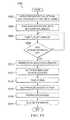
- method 900is an example method of placing MEMS sensors in a wellbore and gathering data.
- data sensorsare selected based on the parameter(s) or other conditions to be determined or sensed within the wellbore.
- a quantity of data sensorsis mixed with a wellbore composition, for example a sealant slurry.
- data sensorsare added to a sealant by any methods known to those of skill in the art.
- the sensorsmay be mixed with a dry material, mixed with one more liquid components (e.g., water or a non-aqueous fluid), or combinations thereof. The mixing may occur onsite, for example addition of the sensors into a bulk mixer such as a cement slurry mixer.
- the sensorsmay be added directly to the mixer, may be added to one or more component streams and subsequently fed to the mixer, may be added downstream of the mixer, or combinations thereof.
- data sensorscan be added after a blending unit and slurry pump, for example, through a lateral by-pass.
- the sensorsmay be metered in and mixed at the well site, or may be pre-mixed into the composition (or one or more components thereof) and subsequently transported to the well site.
- the sensorsmay be dry mixed with dry cement and transported to the well site where a cement slurry is formed comprising the sensors.
- the sensorsmay be pre-mixed with one or more liquid components (e.g., mix water) and transported to the well site where a cement slurry is formed comprising the sensors.
- liquid componentse.g., mix water
- the properties of the wellbore composition or components thereofmay be such that the sensors distributed or dispersed therein do not substantially settle during transport or placement.
- the sealant slurryis then pumped downhole at block 906 , whereby the sensors are positioned within the wellbore.
- the sensorsmay extend along all or a portion of the length of the wellbore adjacent the casing.
- the sealant slurrymay be placed downhole as part of a primary cementing, secondary cementing, or other sealant operation as described in more detail herein.
- a data interrogator toolis positioned in an operable location to gather data from the sensors, for example lowered within the wellbore proximate the sensors.
- the data interrogator toolinterrogates the data sensors (e.g., by sending out an RF signal) while the data interrogator tool traverses all or a portion of the wellbore containing the sensors.
- the data sensorsare activated to record and/or transmit data at block 912 via the signal from the data interrogator tool.
- the data interrogator toolcommunicates the data to one or more computer components (e.g., memory and/or microprocessor) that may be located within the tool, at the surface, or both.
- the datamay be used locally or remotely from the tool to calculate the location of each data sensor and correlate the measured parameter(s) to such locations to evaluate sealant performance.
- a data interrogator toolmay be positioned in wellbore 106 , as at block 908 of FIG. 9 .
- the wipermay be equipped with a data interrogator tool and may read data from the MEMS while being pumped downhole and transmit same to the surface.
- an interrogator toolmay be run into the wellbore following completion of cementing a segment of casing, for example as part of the drill string during resumed drilling operations.
- the interrogator toolmay be run downhole via a wireline or other conveyance. The data interrogator tool may then be signaled to interrogate the sensors (block 910 of FIG.
- the data interrogator toolcommunicates the data to a processor 914 whereby data sensor (and likewise cement slurry) position and cement integrity may be determined via analyzing sensed parameters for changes, trends, expected values, etc. For example, such data may reveal conditions that may be adverse to cement curing.
- the sensorsmay provide a temperature profile over the length of the cement sheath, with a uniform temperature profile likewise indicating a uniform cure (e.g., produced via heat of hydration of the cement during curing) or a cooler zone might indicate the presence of water that may degrade the cement during the transition from slurry to set cement.
- such datamay indicate a zone of reduced, minimal, or missing sensors, which would indicate a loss of cement corresponding to the area (e.g., a loss/void zone or water influx/washout).
- a loss/void zone or water influx/washoute.g., a loss/void zone or water influx/washout.
- fluid from the cement slurrymay leak off into existing low pressure zones traversed by the wellbore. This may adversely affect the cement, and incur undesirable expense for remedial cementing operations (e.g., squeeze cementing as discussed hereinbelow) to position the cement in the annulus. Such leak off may be detected via the present disclosure as described previously. Additionally, conventional circulating cementing may be time-consuming, and therefore relatively expensive, because cement is pumped all the way down tubing string 116 and back up annulus 122 .
- Reverse circulation cementingis a term of art used to describe a method where a cement slurry is pumped down casing annulus 122 instead of into tubing string 116 .
- the cement slurrydisplaces any fluid as it is pumped down annulus 122 .
- Fluid in the annulusis forced down annulus 122 , into tubing string 116 (along with any fluid in the casing), and then back up to earth's surface 112 .
- casing shoe 132comprises a valve that is adjusted to allow flow into the tubing string 116 and then sealed after the cementing operation is complete.
- sealant slurriescomprising MEMS data sensors are pumped down the annulus in reverse circulation applications, a data interrogator is located within the wellbore (e.g., integrated into the casing shoe) and sealant performance is monitored as described with respect to the conventional primary sealing method disclosed hereinabove. Additionally, the data sensors of the present disclosure may also be used to determine completion of a reverse circulation operation, as further discussed hereinbelow.
- Secondary cementing within a wellboremay be carried out subsequent to primary cementing operations.
- a common example of secondary cementingis squeeze cementing wherein a sealant such as a cement composition is forced under pressure into one or more permeable zones within the wellbore to seal such zones.
- permeable zonesinclude fissures, cracks, fractures, streaks, flow channels, voids, high permeability streaks, annular voids, or combinations thereof.
- the permeable zonesmay be present in the cement column residing in the annulus, a wall of the conduit in the wellbore, a microannulus between the cement column and the subterranean formation, and/or a microannulus between the cement column and the conduit.
- the sealant(e.g., secondary cement composition) sets within the permeable zones, thereby forming a hard mass to plug those zones and prevent fluid from passing therethrough, i.e., substantially prevents communication of fluids between the wellbore and the formation via the permeable zone.
- a sealant compositioncomprising MEMS sensors is used to repair holes, channels, voids, and microannuli in casing, cement sheath, gravel packs, and the like as described in U.S. Pat. Nos. 5,121,795; 5,123,487; and 5,127,473, each of which is incorporated by reference herein in its entirety.
- the method of the present disclosuremay be employed in a secondary cementing operation.
- data sensorsare mixed with a sealant composition (e.g., a secondary cement slurry) at block 904 of FIG. 9 and subsequent or during positioning and hardening of the cement, the sensors are interrogated to monitor the performance of the secondary cement in an analogous manner to the incorporation and monitoring of the data sensors in primary cementing methods disclosed hereinabove.
- the MEMS sensorsmay be used to verify that the secondary sealant is functioning properly and/or to monitor its long-term integrity.
- the methods of the present disclosureare utilized for monitoring cementitious sealants (e.g., hydraulic cement), non-cementitious (e.g., polymer, latex or resin systems), or combinations thereof, which may be used in primary, secondary, or other sealing applications.
- cementitious sealantse.g., hydraulic cement
- non-cementitiouse.g., polymer, latex or resin systems
- combinations thereofwhich may be used in primary, secondary, or other sealing applications.
- expandable tubularssuch as pipe, pipe string, casing, liner, or the like are often sealed in a subterranean formation.
- the expandable tubulare.g., casing
- a sealing compositionis placed into the wellbore
- the expandable tubularis expanded, and the sealing composition is allowed to set in the wellbore.
- a mandrelmay be run through the casing to expand the casing diametrically, with expansions up to 25% possible.
- the expandable tubularmay be placed in the wellbore before or after placing the sealing composition in the wellbore.
- the expandable tubularmay be expanded before, during, or after the set of the sealing composition.
- resilient compositionswill remain competent due to their elasticity and compressibility.
- Additional tubularsmay be used to extend the wellbore into the subterranean formation below the first tubular as is known to those of skill in the art. Sealant compositions and methods of using the compositions with expandable tubulars are disclosed in U.S. Pat. Nos.
- the sealantsmay comprise compressible hydraulic cement compositions and/or non-cementitious compositions.
- Compressible hydraulic cement compositionshave been developed which remain competent (continue to support and seal the pipe) when compressed, and such compositions may comprise MEMS sensors.
- the sealant compositionis placed in the annulus between the wellbore and the pipe or pipe string, the sealant is allowed to harden into an impermeable mass, and thereafter, the expandable pipe or pipe string is expanded whereby the hardened sealant composition is compressed.
- the compressible foamed sealant compositioncomprises a hydraulic cement, a rubber latex, a rubber latex stabilizer, a gas and a mixture of foaming and foam stabilizing surfactants.
- Suitable hydraulic cementsinclude, but are not limited to, Portland cement and calcium aluminate cement.
- the settable compositionmay include a polymeric additive.
- the polymer additivemay be a monomer, a pre-polymer, an oligomer, or a short chain polymer that polymerizes in response to the sonic signal.
- activatorsmay include a free-radical dopant that releases autocatalytic free radicals in response to the sonic signal such that the released autocatalytic free radicals initiate polymerization of at least a portion of the settable composition.
- non-cementitious resilient sealantswith comparable strength to cement, but greater elasticity and compressibility, are required for cementing expandable casing.
- these sealantscomprise polymeric sealing compositions, and such compositions may comprise MEMS sensors.
- the sealants compositioncomprises a polymer and a metal containing compound.
- the polymercomprises copolymers, terpolymers, and interpolymers.
- the metal-containing compoundsmay comprise zinc, tin, iron, selenium magnesium, chromium, or cadmium.
- the compoundsmay be in the form of an oxide, carboxylic acid salt, a complex with dithiocarbamate ligand, or a complex with mercaptobenzothiazole ligand.
- the sealantcomprises a mixture of latex, dithio carbamate, zinc oxide, and sulfur.
- the methods of the present disclosurecomprise adding data sensors to a sealant to be used behind expandable casing to monitor the integrity of the sealant upon expansion of the casing and during the service life of the sealant.
- the sensorsmay comprise MEMS sensors capable of measuring, for example, moisture and/or temperature change. If the sealant develops cracks, water influx may thus be detected via moisture and/or temperature indication.
- the MEMS sensorare added to one or more wellbore servicing compositions used or placed downhole in drilling or completing a monodiameter wellbore as disclosed in U.S. Pat. No. 7,066,284 and U.S. Pat. Pub. No. 2005/0241855, each of which is incorporated by reference herein in its entirety.
- the MEMS sensorsare included in a chemical casing composition used in a monodiameter wellbore.
- the MEMS sensorsare included in compositions (e.g., sealants) used to place expandable casing or tubulars in a monodiameter wellbore. Examples of chemical casings are disclosed in U.S. Pat. Nos. 6,702,044; 6,823,940; and 6,848,519, each of which is incorporated herein by reference in its entirety.
- the MEMS sensorsare used to gather sealant data and monitor the long-term integrity of the sealant composition placed in a wellbore, for example a wellbore for the recovery of natural resources such as water or hydrocarbons or an injection well for disposal or storage.
- data/information gathered and/or derived from MEMS sensors in a downhole wellbore sealantcomprises at least a portion of the input and/or output to into one or more calculators, simulations, or models used to predict, select, and/or monitor the performance of wellbore sealant compositions over the life of a well.
- Such models and simulatorsmay be used to select a sealant composition comprising MEMS for use in a wellbore.
- the MEMS sensorsmay provide data that can be used to refine, recalibrate, or correct the models and simulators. Furthermore, the MEMS sensors can be used to monitor and record the downhole conditions that the sealant is subjected to, and sealant performance may be correlated to such long term data to provide an indication of problems or the potential for problems in the same or different wellbores. In various implementations, data gathered from MEMS sensors is used to select a sealant composition or otherwise evaluate or monitor such sealants, as disclosed in U.S. Pat. Nos. 6,697,738; 6,922,637; and 7,133,778, each of which is incorporated by reference herein in its entirety.
- actual measured conditions experienced during the life of the wellin addition to or in lieu of the estimated conditions, may be used. Such actual measured conditions may be obtained for example via sealant compositions comprising MEMS sensors as described herein.
- Effectiveness considerationsinclude concerns that the sealant composition be stable under downhole conditions of pressure and temperature, resist downhole chemicals, and possess the mechanical properties to withstand stresses from various downhole operations to provide zonal isolation for the life of the well.
- step 1102well input data for a particular well is determined.
- Well input dataincludes routinely measurable or calculable parameters inherent in a well, including vertical depth of the well, overburden gradient, pore pressure, maximum and minimum horizontal stresses, hole size, casing outer diameter, casing inner diameter, density of drilling fluid, desired density of sealant slurry for pumping, density of completion fluid, and top of sealant.
- the wellcan be computer modeled. In modeling, the stress state in the well at the end of drilling, and before the sealant slurry is pumped into the annular space, affects the stress state for the interface boundary between the rock and the sealant composition.
- well input dataincludes data that is obtained via sealant compositions comprising MEMS sensors as described herein.
- the well events applicable to the wellare determined.
- cement hydration(setting) is a well event.
- Other well eventsinclude pressure testing, well completions, hydraulic fracturing, hydrocarbon production, fluid injection, perforation, subsequent drilling, formation movement as a result of producing hydrocarbons at high rates from unconsolidated formation, and tectonic movement after the sealant composition has been pumped in place.
- Well eventsinclude those events that are certain to happen during the life of the well, such as cement hydration, and those events that are readily predicted to occur during the life of the well, given a particular well's location, rock type, and other factors well known in the art.
- well events and data associated therewithmay be obtained via sealant compositions comprising MEMS sensors as described herein.
- Each well eventis associated with a certain type of stress, for example, cement hydration is associated with shrinkage, pressure testing is associated with pressure, well completions, hydraulic fracturing, and hydrocarbon production are associated with pressure and temperature, fluid injection is associated with temperature, formation movement is associated with load, and perforation and subsequent drilling are associated with dynamic load.
- each type of stresscan be characterized by an equation for the stress state (collectively “well event stress states”), as described in more detail in U.S. Pat. No. 7,133,778 which is incorporated herein by reference in its entirety.
- step 1106the well input data, the well event stress states, and the sealant data are used to determine the effect of well events on the integrity of the sealant sheath during the life of the well for each of the sealant compositions.
- the sealant compositions that would be effective for sealing the subterranean zone and their capacity from its elastic limitare determined.
- the estimated effects over the life of the wellare compared to and/or corrected in comparison to corresponding actual data gathered over the life of the well via sealant compositions comprising MEMS sensors as described herein.
- Step 1106concludes by determining which sealant compositions would be effective in maintaining the integrity of the resulting cement sheath for the life of the well.
- step 1108parameters for risk of sealant failure for the effective sealant compositions are determined. For example, even though a sealant composition is deemed effective, one sealant composition may be more effective than another.
- the risk parametersare calculated as percentages of sealant competency during the determination of effectiveness in step 1106 .
- the risk parametersare compared to and/or corrected in comparison to actual data gathered over the life of the well via sealant compositions comprising MEMS sensors as described herein.
- Step 1108provides data that allows a user to perform a cost benefit analysis. Due to the high cost of remedial operations, it is important that an effective sealant composition is selected for the conditions anticipated to be experienced during the life of the well. It is understood that each of the sealant compositions has a readily calculable monetary cost. Under certain conditions, several sealant compositions may be equally efficacious, yet one may have the added virtue of being less expensive. Thus, it should be used to minimize costs. More commonly, one sealant composition will be more efficacious, but also more expensive. Accordingly, in step 1110 , an effective sealant composition with acceptable risk parameters is selected given the desired cost.
- steps 1102 - 1110can be compared to actual data that is obtained via sealant compositions comprising MEMS sensors as described herein, and such data may be used to modify and/or correct the inputs and/or outputs to the various steps 1102 - 1110 to improve the accuracy of same.
- wipersare often utilized during conventional primary cementing to force cement slurry out of the casing.
- the wiper plugalso serves another purpose: typically, the end of a cementing operation is signaled when the wiper plug contacts a restriction (e.g., casing shoe) inside the tubing string 116 at the bottom of the string. When the plug contacts the restriction, a sudden pressure increase at pump 130 is registered. In this way, it can be determined when the cement has been displaced from the tubing string 116 and fluid flow returning to the surface via casing annulus 122 stops.
- a restrictione.g., casing shoe
- the methods disclosed hereinmay be utilized to determine when cement slurry has been appropriately positioned downhole. Furthermore, as discussed hereinbelow, the methods of the present disclosure may additionally comprise using a MEMS sensor to actuate a valve or other mechanical means to close and prevent cement from entering the casing upon determination of completion of a cementing operation.
- FIG. 10is a flowchart of a method for determining completion of a cementing operation and optionally further actuating a downhole tool upon completion (or to initiate completion) of the cementing operation. This description will reference the flowchart of FIG. 10 , as well as the wellbore depiction of FIG. 1 .
- a data interrogator tool as described hereinaboveis positioned at the far end of tubing string 116 .
- the data interrogator toolis incorporated with or adjacent to a casing shoe positioned at the bottom end of the casing and in communication with operators at the surface.
- MEMS sensorsare added to a fluid (e.g., cement slurry, spacer fluid, displacement fluid, etc.) to be pumped into annulus 122 .
- cement slurryis pumped into annulus 122 .
- MEMS sensorsmay be placed in substantially all of the cement slurry pumped into the wellbore.
- MEMS sensorsmay be placed in a leading plug or otherwise placed in an initial portion of the cement to indicate a leading edge of the cement slurry.
- MEMS sensorsare placed in leading and trailing plugs to signal the beginning and end of the cement slurry.
- the data interrogator toolDIT
- the data interrogator tooldetects whether the data sensors are in communicative proximity with the data interrogator tool. As long as no data sensors are detected, the pumping of additional cement into the annulus continues.
- the interrogator tooldetects the sensors at block 1010 indicating that the leading edge of the cement has reached the bottom of the casing, the interrogator sends a signal to terminate pumping.
- the cement in the annulusis allowed to set and form a substantially impermeable mass which physically supports and positions the casing in the wellbore and bonds the casing to the walls of the wellbore in block 1020 .
- MEMS-based data sensorsare incorporated within the set cement, and parameters of the cement (e.g., temperature, pressure, ion concentration, stress, strain, etc.) can be monitored during placement and for the duration of the service life of the cement according to methods disclosed hereinabove.
- the data sensorsmay be added to an interface fluid (e.g., spacer fluid or other fluid plug) introduced into the annulus prior to and/or after introduction of cement slurry into the annulus.
- a valve or other toolmay be operably associated with a data interrogator tool at the far end of the casing.
- This valvemay be contained within float shoe 132 , for example, as disclosed hereinabove.
- float shoe 132may contain an integral data interrogator tool, or may otherwise be coupled to a data interrogator tool.
- the data interrogator toolmay be positioned between tubing string 116 and float shoe 132 .
- pumpingcontinues as the data interrogator tool detects the presence or absence of data sensors in close proximity to the interrogator tool (dependent upon the specific method cementing method being employed, e.g., reverse circulation, and the positioning of the sensors within the cement flow).
- the data interrogator toolUpon detection of a determinative presence or absence of sensors in close proximity indicating the termination of the cement slurry, the data interrogator tool sends a signal to actuate the tool (e.g., valve) at block 1012 .
- the valvecloses, sealing the casing and preventing cement from entering the portion of casing string above the valve in a reverse cementing operation.
- the closing of the valve at 1016causes an increase in back pressure that is detected at the hydraulic pump 130 .
- pumpingis discontinued, and cement is allowed to set in the annulus at block 1020 .
- parameters of the cementcan additionally be monitored during placement and for the duration of the service life of the cement according to methods disclosed hereinabove.
- Improved methods of monitoring wellbore sealant condition from placement through the service lifetime of the sealant as disclosed hereinprovide a number of advantages. Such methods are capable of detecting changes in parameters in wellbore sealant such as moisture content, temperature, pH, and the concentration of ions (e.g., chloride, sodium, and potassium ions). Such methods provide this data for monitoring the condition of sealant from the initial quality control period during mixing and/or placement, through the sealant's useful service life, and through its period of deterioration and/or repair. Such methods are cost efficient and allow determination of real-time data using sensors capable of functioning without the need for a direct power source (i.e., passive rather than active sensors), such that sensor size be minimal to maintain sealant strength and sealant slurry pumpability.
- ionse.g., chloride, sodium, and potassium ions
- MEMS sensorsfor determining wellbore characteristics or parameters may also be utilized in methods of pricing a well servicing treatment, selecting a treatment for the well servicing operation, and/or monitoring a well servicing treatment during real-time performance thereof, for example, as described in U.S. Pat. Pub. No. 2006/0047527 A1, which is incorporated by reference herein in its entirety.
Landscapes
- Engineering & Computer Science (AREA)
- Chemical & Material Sciences (AREA)
- Life Sciences & Earth Sciences (AREA)
- Mining & Mineral Resources (AREA)
- Geology (AREA)
- General Life Sciences & Earth Sciences (AREA)
- Physics & Mathematics (AREA)
- Ceramic Engineering (AREA)
- Materials Engineering (AREA)
- Organic Chemistry (AREA)
- Geochemistry & Mineralogy (AREA)
- Environmental & Geological Engineering (AREA)
- Fluid Mechanics (AREA)
- Structural Engineering (AREA)
- Inorganic Chemistry (AREA)
- Chemical Kinetics & Catalysis (AREA)
- Analytical Chemistry (AREA)
- Geophysics (AREA)
- Remote Sensing (AREA)
- Quality & Reliability (AREA)
- Electromagnetism (AREA)
- Preparation Of Clay, And Manufacture Of Mixtures Containing Clay Or Cement (AREA)
- Investigating Or Analyzing Materials By The Use Of Ultrasonic Waves (AREA)
- Soil Conditioners And Soil-Stabilizing Materials (AREA)
- Treatment Of Sludge (AREA)
- Consolidation Of Soil By Introduction Of Solidifying Substances Into Soil (AREA)
- Sealing Material Composition (AREA)
- Processing Of Solid Wastes (AREA)
- Branch Pipes, Bends, And The Like (AREA)
- Excavating Of Shafts Or Tunnels (AREA)
Abstract
Description
Claims (22)
Priority Applications (8)
| Application Number | Priority Date | Filing Date | Title |
|---|---|---|---|
| US12/547,233US8162055B2 (en) | 2007-04-02 | 2009-08-25 | Methods of activating compositions in subterranean zones |
| PCT/GB2010/001590WO2011023942A2 (en) | 2009-08-25 | 2010-08-23 | Methods of activating compositions in subterranean zones |
| CA 2771626CA2771626C (en) | 2009-08-25 | 2010-08-23 | Methods of activating compositions in subterranean zones |
| BR112012004180-0ABR112012004180B1 (en) | 2009-08-25 | 2010-08-23 | METHOD TO TREAT UNDERGROUND TRAINING AND ACTIVATION DEVICE |
| MX2012002397AMX339042B (en) | 2009-08-25 | 2010-08-23 | Methods of activating compositions in subterranean zones. |
| GB1205235.3AGB2486138B (en) | 2009-08-25 | 2010-08-23 | Methods of activating compositions in subterranean zones |
| ARP100103082AR077946A1 (en) | 2009-08-25 | 2010-08-24 | METHODS TO ACTIVATE COMPOSITIONS IN UNDERGROUND AREAS |
| NO20120198ANO344321B1 (en) | 2009-08-25 | 2012-02-24 | A method of treating an underground formation and activating device for use in the method |
Applications Claiming Priority (2)
| Application Number | Priority Date | Filing Date | Title |
|---|---|---|---|
| US11/695,329US7712527B2 (en) | 2007-04-02 | 2007-04-02 | Use of micro-electro-mechanical systems (MEMS) in well treatments |
| US12/547,233US8162055B2 (en) | 2007-04-02 | 2009-08-25 | Methods of activating compositions in subterranean zones |
Related Parent Applications (1)
| Application Number | Title | Priority Date | Filing Date |
|---|---|---|---|
| US11/695,329Continuation-In-PartUS7712527B2 (en) | 2007-04-02 | 2007-04-02 | Use of micro-electro-mechanical systems (MEMS) in well treatments |
Publications (2)
| Publication Number | Publication Date |
|---|---|
| US20100051275A1 US20100051275A1 (en) | 2010-03-04 |
| US8162055B2true US8162055B2 (en) | 2012-04-24 |
Family
ID=43628485
Family Applications (1)
| Application Number | Title | Priority Date | Filing Date |
|---|---|---|---|
| US12/547,233Active2028-08-05US8162055B2 (en) | 2007-04-02 | 2009-08-25 | Methods of activating compositions in subterranean zones |
Country Status (8)
| Country | Link |
|---|---|
| US (1) | US8162055B2 (en) |
| AR (1) | AR077946A1 (en) |
| BR (1) | BR112012004180B1 (en) |
| CA (1) | CA2771626C (en) |
| GB (1) | GB2486138B (en) |
| MX (1) | MX339042B (en) |
| NO (1) | NO344321B1 (en) |
| WO (1) | WO2011023942A2 (en) |
Cited By (22)
| Publication number | Priority date | Publication date | Assignee | Title |
|---|---|---|---|---|
| US20110158050A1 (en)* | 2009-12-28 | 2011-06-30 | Carlos Merino | Wireless network discovery algorithm and system |
| US20110214853A1 (en)* | 2010-03-03 | 2011-09-08 | Blackhawk Specialty Tools , LLC | Tattle-tale apparatus |
| US9006154B2 (en) | 2005-09-09 | 2015-04-14 | Halliburton Energy Services, Inc. | Methods for determining reactive index for cement kiln dust, associated compositions and methods of use |
| US9006155B2 (en) | 2005-09-09 | 2015-04-14 | Halliburton Energy Services, Inc. | Placing a fluid comprising kiln dust in a wellbore through a bottom hole assembly |
| US9051505B2 (en) | 2005-09-09 | 2015-06-09 | Halliburton Energy Services, Inc. | Placing a fluid comprising kiln dust in a wellbore through a bottom hole assembly |
| US9150773B2 (en) | 2005-09-09 | 2015-10-06 | Halliburton Energy Services, Inc. | Compositions comprising kiln dust and wollastonite and methods of use in subterranean formations |
| US9194207B2 (en) | 2007-04-02 | 2015-11-24 | Halliburton Energy Services, Inc. | Surface wellbore operating equipment utilizing MEMS sensors |
| US9200500B2 (en) | 2007-04-02 | 2015-12-01 | Halliburton Energy Services, Inc. | Use of sensors coated with elastomer for subterranean operations |
| US9376609B2 (en) | 2010-12-21 | 2016-06-28 | Halliburton Energy Services, Inc. | Settable compositions comprising interground perlite and hydraulic cement |
| US9686021B2 (en) | 2011-03-30 | 2017-06-20 | Schlumberger Technology Corporation | Wireless network discovery and path optimization algorithm and system |
| US9822631B2 (en) | 2007-04-02 | 2017-11-21 | Halliburton Energy Services, Inc. | Monitoring downhole parameters using MEMS |
| US9903184B2 (en) | 2005-09-09 | 2018-02-27 | Halliburton Energy Services, Inc. | Consolidating spacer fluids and methods of use |
| US20180238168A1 (en)* | 2015-09-18 | 2018-08-23 | Halliburton Energy Services, Inc. | Contrast enhancement agents for subterranean treatment fluids |
| US10323509B2 (en) | 2015-03-20 | 2019-06-18 | Halliburton Energy Services, Inc. | Repeater for a wellbore |
| US10465499B2 (en)* | 2015-03-31 | 2019-11-05 | Halliburton Energy Services, Inc. | Underground GPS for use in plug tracking |
| US10519765B2 (en)* | 2015-03-31 | 2019-12-31 | Halliburton Energy Services, Inc. | Plug tracking using through-the-earth communication system |
| US10662728B2 (en)* | 2018-07-09 | 2020-05-26 | Saudi Arabian Oil Company | Method and apparatus for stuck pipe mitigation |
| US10738590B2 (en) | 2015-03-20 | 2020-08-11 | Halliburton Energy Services Inc. | Dynamic sensing of the top of cement (TOC) during cementing of a well casing in a well bore |
| US10961845B2 (en) | 2015-03-27 | 2021-03-30 | Halliburton Energy Services, Inc. | Casing coupling having communication unit for evaluating downhole conditions |
| US11519263B2 (en) | 2015-01-26 | 2022-12-06 | Halliburton Energy Services, Inc. | Traceable micro-electro-mechanical systems for use in subterranean formations |
| US20240167360A1 (en)* | 2020-10-14 | 2024-05-23 | John Tyler Thomason | Payload deployment tools and methods of using same |
| WO2025137165A1 (en) | 2023-12-20 | 2025-06-26 | Shell Usa, Inc. | Method for subsea cementing |
Families Citing this family (91)
| Publication number | Priority date | Publication date | Assignee | Title |
|---|---|---|---|---|
| US8522873B2 (en) | 2005-09-09 | 2013-09-03 | Halliburton Energy Services, Inc. | Spacer fluids containing cement kiln dust and methods of use |
| US8950486B2 (en) | 2005-09-09 | 2015-02-10 | Halliburton Energy Services, Inc. | Acid-soluble cement compositions comprising cement kiln dust and methods of use |
| US9023150B2 (en) | 2005-09-09 | 2015-05-05 | Halliburton Energy Services, Inc. | Acid-soluble cement compositions comprising cement kiln dust and/or a natural pozzolan and methods of use |
| US8555967B2 (en)* | 2005-09-09 | 2013-10-15 | Halliburton Energy Services, Inc. | Methods and systems for evaluating a boundary between a consolidating spacer fluid and a cement composition |
| US8281859B2 (en) | 2005-09-09 | 2012-10-09 | Halliburton Energy Services Inc. | Methods and compositions comprising cement kiln dust having an altered particle size |
| US9809737B2 (en) | 2005-09-09 | 2017-11-07 | Halliburton Energy Services, Inc. | Compositions containing kiln dust and/or biowaste ash and methods of use |
| US8505629B2 (en) | 2005-09-09 | 2013-08-13 | Halliburton Energy Services, Inc. | Foamed spacer fluids containing cement kiln dust and methods of use |
| US9676989B2 (en) | 2005-09-09 | 2017-06-13 | Halliburton Energy Services, Inc. | Sealant compositions comprising cement kiln dust and tire-rubber particles and method of use |
| US8770261B2 (en) | 2006-02-09 | 2014-07-08 | Schlumberger Technology Corporation | Methods of manufacturing degradable alloys and products made from degradable alloys |
| US20110067889A1 (en)* | 2006-02-09 | 2011-03-24 | Schlumberger Technology Corporation | Expandable and degradable downhole hydraulic regulating assembly |
| US8316936B2 (en) | 2007-04-02 | 2012-11-27 | Halliburton Energy Services Inc. | Use of micro-electro-mechanical systems (MEMS) in well treatments |
| US9394756B2 (en)* | 2007-04-02 | 2016-07-19 | Halliburton Energy Services, Inc. | Timeline from slumber to collection of RFID tags in a well environment |
| US8342242B2 (en) | 2007-04-02 | 2013-01-01 | Halliburton Energy Services, Inc. | Use of micro-electro-mechanical systems MEMS in well treatments |
| US9732584B2 (en) | 2007-04-02 | 2017-08-15 | Halliburton Energy Services, Inc. | Use of micro-electro-mechanical systems (MEMS) in well treatments |
| US8302686B2 (en) | 2007-04-02 | 2012-11-06 | Halliburton Energy Services Inc. | Use of micro-electro-mechanical systems (MEMS) in well treatments |
| US8297352B2 (en) | 2007-04-02 | 2012-10-30 | Halliburton Energy Services, Inc. | Use of micro-electro-mechanical systems (MEMS) in well treatments |
| US10358914B2 (en) | 2007-04-02 | 2019-07-23 | Halliburton Energy Services, Inc. | Methods and systems for detecting RFID tags in a borehole environment |
| US9394784B2 (en)* | 2007-04-02 | 2016-07-19 | Halliburton Energy Services, Inc. | Algorithm for zonal fault detection in a well environment |
| US9879519B2 (en) | 2007-04-02 | 2018-01-30 | Halliburton Energy Services, Inc. | Methods and apparatus for evaluating downhole conditions through fluid sensing |
| US9394785B2 (en)* | 2007-04-02 | 2016-07-19 | Halliburton Energy Services, Inc. | Methods and apparatus for evaluating downhole conditions through RFID sensing |
| US8297353B2 (en) | 2007-04-02 | 2012-10-30 | Halliburton Energy Services, Inc. | Use of micro-electro-mechanical systems (MEMS) in well treatments |
| US8291975B2 (en) | 2007-04-02 | 2012-10-23 | Halliburton Energy Services Inc. | Use of micro-electro-mechanical systems (MEMS) in well treatments |
| US8162050B2 (en) | 2007-04-02 | 2012-04-24 | Halliburton Energy Services Inc. | Use of micro-electro-mechanical systems (MEMS) in well treatments |
| US9494032B2 (en) | 2007-04-02 | 2016-11-15 | Halliburton Energy Services, Inc. | Methods and apparatus for evaluating downhole conditions with RFID MEMS sensors |
| US8083849B2 (en)* | 2007-04-02 | 2011-12-27 | Halliburton Energy Services, Inc. | Activating compositions in subterranean zones |
| US8162055B2 (en) | 2007-04-02 | 2012-04-24 | Halliburton Energy Services Inc. | Methods of activating compositions in subterranean zones |
| US8397810B2 (en)* | 2007-06-25 | 2013-03-19 | Turbo-Chem International, Inc. | Wireless tag tracer method |
| US20080316049A1 (en)* | 2007-06-25 | 2008-12-25 | Turbo-Chem International, Inc. | RFID Tag Tracer Method and Apparatus |
| US8047282B2 (en)* | 2009-08-25 | 2011-11-01 | Halliburton Energy Services Inc. | Methods of sonically activating cement compositions |
| US8215393B2 (en)* | 2009-10-06 | 2012-07-10 | Schlumberger Technology Corporation | Method for treating well bore within a subterranean formation |
| US8424598B2 (en)* | 2010-09-21 | 2013-04-23 | Halliburton Energy Services, Inc. | Magnetically controlled delivery of subterranean fluid additives for use in subterranean applications |
| US8662173B2 (en) | 2011-04-11 | 2014-03-04 | Saudi Arabian Oil Company | Plugging thief zones and fractures by in-situ and in-depth crystallization for improving water sweep efficiency of sandstone and carbonate reservoirs |
| GB201108098D0 (en) | 2011-05-16 | 2011-06-29 | Intelligent Well Controls Ltd | Determining whether a wellbore cementation operation has been performed correctly |
| US20130002268A1 (en)* | 2011-06-30 | 2013-01-03 | Baker Hughes Incorporated | Distributed sensors to measure cement state |
| US9261461B2 (en) | 2011-08-05 | 2016-02-16 | Halliburton Energy Services, Inc. | Systems and methods for monitoring oil/gas separation processes |
| US8997860B2 (en) | 2011-08-05 | 2015-04-07 | Halliburton Energy Services, Inc. | Methods for monitoring the formation and transport of a fracturing fluid using opticoanalytical devices |
| US8960294B2 (en) | 2011-08-05 | 2015-02-24 | Halliburton Energy Services, Inc. | Methods for monitoring fluids within or produced from a subterranean formation during fracturing operations using opticoanalytical devices |
| US9222892B2 (en) | 2011-08-05 | 2015-12-29 | Halliburton Energy Services, Inc. | Systems and methods for monitoring the quality of a fluid |
| US9222348B2 (en) | 2011-08-05 | 2015-12-29 | Halliburton Energy Services, Inc. | Methods for monitoring the formation and transport of an acidizing fluid using opticoanalytical devices |
| US9182355B2 (en) | 2011-08-05 | 2015-11-10 | Halliburton Energy Services, Inc. | Systems and methods for monitoring a flow path |
| US9206386B2 (en) | 2011-08-05 | 2015-12-08 | Halliburton Energy Services, Inc. | Systems and methods for analyzing microbiological substances |
| US9395306B2 (en) | 2011-08-05 | 2016-07-19 | Halliburton Energy Services, Inc. | Methods for monitoring fluids within or produced from a subterranean formation during acidizing operations using opticoanalytical devices |
| US9297254B2 (en) | 2011-08-05 | 2016-03-29 | Halliburton Energy Services, Inc. | Methods for monitoring fluids within or produced from a subterranean formation using opticoanalytical devices |
| US9441149B2 (en) | 2011-08-05 | 2016-09-13 | Halliburton Energy Services, Inc. | Methods for monitoring the formation and transport of a treatment fluid using opticoanalytical devices |
| US8908165B2 (en) | 2011-08-05 | 2014-12-09 | Halliburton Energy Services, Inc. | Systems and methods for monitoring oil/gas separation processes |
| US20130043027A1 (en)* | 2011-08-18 | 2013-02-21 | Schlumberger Technology Corporation | Zonal Isolation Systems For Subterranean Wells |
| US20130136539A1 (en)* | 2011-11-30 | 2013-05-30 | James Alvin Aardema | Paving system utilizing embedded measuring devices |
| US20130136535A1 (en)* | 2011-11-30 | 2013-05-30 | James A. Aardema | Paving system utilizing capsules enclosing a dye |
| US9227872B2 (en) | 2012-03-09 | 2016-01-05 | Halliburton Energy Services, Inc. | Cement set activators for set-delayed cement compositions and associated methods |
| US9796904B2 (en)* | 2012-03-09 | 2017-10-24 | Halliburton Energy Services, Inc. | Use of MEMS in set-delayed cement compositions comprising pumice |
| US9019501B2 (en) | 2012-04-26 | 2015-04-28 | Halliburton Energy Services, Inc. | Methods and devices for optically determining a characteristic of a substance |
| US8912477B2 (en) | 2012-04-26 | 2014-12-16 | Halliburton Energy Services, Inc. | Methods and devices for optically determining a characteristic of a substance |
| US8941046B2 (en) | 2012-04-26 | 2015-01-27 | Halliburton Energy Services, Inc. | Methods and devices for optically determining a characteristic of a substance |
| US9013702B2 (en) | 2012-04-26 | 2015-04-21 | Halliburton Energy Services, Inc. | Imaging systems for optical computing devices |
| US9080943B2 (en) | 2012-04-26 | 2015-07-14 | Halliburton Energy Services, Inc. | Methods and devices for optically determining a characteristic of a substance |
| US9013698B2 (en) | 2012-04-26 | 2015-04-21 | Halliburton Energy Services, Inc. | Imaging systems for optical computing devices |
| US9702811B2 (en) | 2012-04-26 | 2017-07-11 | Halliburton Energy Services, Inc. | Methods and devices for optically determining a characteristic of a substance using integrated computational elements |
| US8879053B2 (en) | 2012-04-26 | 2014-11-04 | Halliburton Energy Services, Inc. | Devices having an integrated computational element and a proximal interferent monitor and methods for determining a characteristic of a sample therewith |
| US8780352B2 (en) | 2012-04-26 | 2014-07-15 | Halliburton Energy Services, Inc. | Methods and devices for optically determining a characteristic of a substance |
| US8823939B2 (en) | 2012-04-26 | 2014-09-02 | Halliburton Energy Services, Inc. | Methods and devices for optically determining a characteristic of a substance |
| US9383307B2 (en) | 2012-04-26 | 2016-07-05 | Halliburton Energy Services, Inc. | Methods and devices for optically determining a characteristic of a substance |
| US9658149B2 (en) | 2012-04-26 | 2017-05-23 | Halliburton Energy Services, Inc. | Devices having one or more integrated computational elements and methods for determining a characteristic of a sample by computationally combining signals produced therewith |
| US9170208B2 (en) | 2012-08-31 | 2015-10-27 | Halliburton Energy Services, Inc. | Handheld characteristic analyzer and methods of using the same |
| US9103716B2 (en) | 2012-08-31 | 2015-08-11 | Halliburton Energy Services, Inc. | Handheld characteristic analyzer and methods of using the same |
| US9176052B2 (en) | 2012-09-14 | 2015-11-03 | Halliburton Energy Services, Inc. | Systems and methods for inspecting and monitoring a pipeline |
| US9228940B2 (en) | 2012-09-14 | 2016-01-05 | Halliburton Energy Services, Inc. | Systems, methods, and apparatuses for in situ monitoring of cement fluid compositions and setting processes thereof |
| US9086383B2 (en) | 2012-09-14 | 2015-07-21 | Halliburton Energy Services, Inc. | Systems and methods for monitoring chemical processes |
| US9222896B2 (en) | 2012-09-14 | 2015-12-29 | Halliburton Energy Services, Inc. | Systems and methods for inspecting and monitoring a pipeline |
| US8765061B2 (en) | 2012-09-14 | 2014-07-01 | Halliburton Energy Services, Inc. | Systems and methods for inspecting and monitoring a pipeline |
| US8619256B1 (en) | 2012-09-14 | 2013-12-31 | Halliburton Energy Services, Inc. | Systems and methods for monitoring the properties of a fluid cement composition in a flow path |
| MY200336A (en) | 2013-03-31 | 2023-12-20 | Halliburton Energy Services Inc | Cement set activators for set-delayed cement compositions and associated methods |
| MX364526B (en) | 2013-07-09 | 2019-04-30 | Halliburton Energy Services Inc | Integrated computational elements with frequency selective surface. |
| EP2994740A4 (en) | 2013-07-09 | 2016-12-28 | Halliburton Energy Services Inc | Integrated computational elements with laterally-distributed spectral filters |
| NO346301B1 (en) | 2013-09-25 | 2022-05-30 | Halliburton Energy Services Inc | Systems and methods for real time measurement of gas content in drilling fluids |
| CA2929576C (en)* | 2013-12-12 | 2019-03-05 | Halliburton Energy Services, Inc. | Settable compositions comprising cement kiln dust and methods of use |
| US9708908B2 (en) | 2014-06-13 | 2017-07-18 | Halliburton Energy Services, Inc. | Integrated computational element with multiple frequency selective surfaces |
| WO2016032437A1 (en) | 2014-08-26 | 2016-03-03 | Halliburton Energy Services, Inc. | Systems and methods for in situ monitoring of cement slurry locations and setting processes thereof |
| GB2542309B (en)* | 2014-08-26 | 2021-10-06 | Halliburton Energy Services Inc | Systems and methods for analyzing the characteristics and compositions of cement additives |
| MY187103A (en)* | 2015-02-28 | 2021-08-31 | Halliburton Energy Services Inc | Use of mems in set-delayed cement compositions comprising pumice |
| AU2015390014B2 (en) | 2015-03-31 | 2018-09-20 | Halliburton Energy Services, Inc. | Plug tracking through surface mounted equipment |
| US10927287B2 (en) | 2015-07-06 | 2021-02-23 | Halliburton Energy Services, Inc. | Extended-life calcium aluminophosphate cement compositions |
| WO2017007455A1 (en)* | 2015-07-07 | 2017-01-12 | 1/Halliburton Energy Services, Inc. | Plugging and abandoning a well using extended-life cement compositions |
| US10125604B2 (en)* | 2015-10-27 | 2018-11-13 | Baker Hughes, A Ge Company, Llc | Downhole zonal isolation detection system having conductor and method |
| US10815768B2 (en)* | 2016-02-15 | 2020-10-27 | Halliburton Energy Services, Inc. | Method of detecting presence of RFID tags and determining properties of surrounding environment in subterranean formation |
| NO20171578A1 (en)* | 2017-10-03 | 2019-04-04 | Experwell As | Method and system for preventing leakage from a well |
| KR102522289B1 (en) | 2018-05-14 | 2023-04-17 | 미쓰이 가가쿠 가부시키가이샤 | Method for injecting thiourethane based monomer in mold for manufacturing optical material |
| CA3112341A1 (en)* | 2018-09-11 | 2020-03-19 | Abb Schweiz Ag | Cable conduit with integrated sensors |
| US11208867B2 (en)* | 2019-07-02 | 2021-12-28 | Halliburton Energy Services, Inc. | System and device for use in performing reverse-cementing operations in downhole well environments |
| US11686196B2 (en) | 2019-12-19 | 2023-06-27 | Saudi Arabian Oil Company | Downhole actuation system and methods with dissolvable ball bearing |
| WO2023101893A1 (en)* | 2021-12-03 | 2023-06-08 | Saudi Arabian Oil Company | Magnetically controlled release of chemicals in a downhole environment |
| US12060764B2 (en) | 2022-09-30 | 2024-08-13 | Halliburton Energy Services, Inc. | Activation of wellbore sealants with ultrasonic waves after placement in a wellbore |
Citations (95)
| Publication number | Priority date | Publication date | Assignee | Title |
|---|---|---|---|---|
| US3239005A (en) | 1964-01-28 | 1966-03-08 | Jr Albert G Bodine | Method of molding well liners and the like |
| US4377087A (en)* | 1979-10-11 | 1983-03-22 | Societe Nationale Elf Aquitaine (Production) | Device for acoustically controlling the setting and hardening characteristics of cements |
| US4512401A (en) | 1982-02-01 | 1985-04-23 | Bodine Albert G | Method for forming a cement annulus for a well |
| US4653587A (en) | 1986-02-19 | 1987-03-31 | Bodine Albert G | Method and apparatus for the sonic cementing of wells in porous formations |
| US4736794A (en) | 1986-02-19 | 1988-04-12 | Bodine Albert G | Method for the sonic cementing of down hole well casings |
| US5204426A (en)* | 1989-04-27 | 1993-04-20 | National Research Development Corporation | Command-curable composition |
| US5261492A (en) | 1992-03-31 | 1993-11-16 | Halliburton Company | Well casing apparatus and method |
| US5277253A (en) | 1992-04-03 | 1994-01-11 | Halliburton Company | Hydraulic set casing packer |
| US5368103A (en) | 1993-09-28 | 1994-11-29 | Halliburton Company | Method of setting a balanced cement plug in a borehole |
| US5437329A (en) | 1994-01-25 | 1995-08-01 | Baker Hughes Incorporated | Method and apparatus for activation of furnace slag base cement |
| US5566757A (en) | 1995-03-23 | 1996-10-22 | Halliburton Company | Method and apparatus for setting sidetrack plugs in open or cased well bores |
| US5613558A (en)* | 1995-06-02 | 1997-03-25 | Bj Services Company | Method for controlling the set time of cement |
| US5829522A (en) | 1996-07-18 | 1998-11-03 | Halliburton Energy Services, Inc. | Sand control screen having increased erosion and collapse resistance |
| US6444316B1 (en)* | 2000-05-05 | 2002-09-03 | Halliburton Energy Services, Inc. | Encapsulated chemicals for use in controlled time release applications and methods |
| US6457524B1 (en) | 2000-09-15 | 2002-10-01 | Halliburton Energy Services, Inc. | Well cementing compositions and methods |
| US20030200903A1 (en)* | 2002-04-29 | 2003-10-30 | Mattus Alfred J. | Controlling the set of carbon-fiber embedded cement with electric current |
| US20030221831A1 (en) | 2002-05-31 | 2003-12-04 | Reddy B. Raghava | Methods of generating gas in well treating fluids |
| US20040047534A1 (en) | 2002-09-09 | 2004-03-11 | Shah Vimal V. | Downhole sensing with fiber in exterior annulus |
| US6739806B1 (en) | 2003-06-13 | 2004-05-25 | Halliburton Energy Services, Inc. | Cement compositions with improved fluid loss characteristics and methods of cementing in subterranean formations |
| US20040180793A1 (en) | 2000-09-09 | 2004-09-16 | Schlumberger Technology Corporation | Method and system for cement lining a wellbore |
| US6818594B1 (en)* | 1999-11-12 | 2004-11-16 | M-I L.L.C. | Method for the triggered release of polymer-degrading agents for oil field use |
| US20050006020A1 (en) | 2001-11-12 | 2005-01-13 | Technische Universiteit Delft | Method of hardening a fluid mass |
| US6868908B2 (en) | 2002-07-23 | 2005-03-22 | Halliburton Energy Services, Inc. | Anti-rotation method and apparatus for limiting rotation of cementing plugs |
| US20050139353A1 (en) | 2003-07-03 | 2005-06-30 | Johnson Howard E.Jr. | Earth loop installation with sonic drilling |
| US6973969B2 (en) | 2003-08-08 | 2005-12-13 | Halliburton Energy Services, Inc. | Apparatus and methods for preventing or limiting rotation of cementing plugs |
| US6978834B1 (en) | 2004-05-26 | 2005-12-27 | Halliburton Energy Services, Inc. | Foamed and non-foamed cement compositions including silane treated amorphous silica and methods |
| GB2391565B (en) | 2002-07-30 | 2006-01-11 | Schlumberger Holdings | Downhole tool control apparatus and methods |
| US20060081372A1 (en) | 2004-10-20 | 2006-04-20 | Halliburton Energy Services, Inc. | Treatment fluids comprising vitrified shale and methods of using such fluids in subterranean formations |
| US20060086503A1 (en) | 2004-10-26 | 2006-04-27 | Halliburton Energy Services | Casing strings and methods of using such strings in subterranean cementing operations |
| US20060086502A1 (en) | 2004-10-26 | 2006-04-27 | Halliburton Energy Services | Casing strings and methods of using such strings in subterranean cementing operations |
| US20060086499A1 (en) | 2004-10-26 | 2006-04-27 | Halliburton Energy Services | Methods and systems for reverse-circulation cementing in subterranean formations |
| US7036586B2 (en) | 2004-01-30 | 2006-05-02 | Halliburton Energy Services, Inc. | Methods of cementing in subterranean formations using crack resistant cement compositions |
| US7067000B1 (en) | 2005-02-22 | 2006-06-27 | Halliburton Energy Services, Inc. | Methods of cementing using a fluid loss control additive |
| US7077203B1 (en) | 2005-09-09 | 2006-07-18 | Halliburton Energy Services, Inc. | Methods of using settable compositions comprising cement kiln dust |
| US20060166834A1 (en) | 2004-02-10 | 2006-07-27 | Halliburton Energy Services, Inc. | Subterranean treatment fluids comprising substantially hydrated cement particulates |
| US20060162926A1 (en) | 2004-02-10 | 2006-07-27 | Halliburton Energy Services, Inc. | Methods of using substantially hydrated cement particulates in subterranean applications |
| US7086466B2 (en) | 2004-02-10 | 2006-08-08 | Halliburton Energy Services, Inc. | Use of substantially hydrated cement particulates in drilling and subterranean applications |
| US20060180309A1 (en) | 2005-02-15 | 2006-08-17 | Halliburton Energy Services, Inc. | Viscoelastic surfactant fluids and associated diverting methods |
| US20060180310A1 (en) | 2005-02-15 | 2006-08-17 | Halliburton Energy Services, Inc. | Viscoelastic surfactant fluids and associated methods |
| US20060180308A1 (en) | 2005-02-15 | 2006-08-17 | Halliburton Energy Services, Inc. | Viscoelastic surfactant fluids and associated acidizing methods |
| US20060183646A1 (en) | 2005-02-15 | 2006-08-17 | Halliburton Energy Services, Inc. | Viscoelastic surfactant fluids and associated methods |
| US20060189487A1 (en) | 2005-02-22 | 2006-08-24 | Halliburton Energy Services, Inc. | Fluid loss control additive and cement compositions comprising same |
| US20060250243A1 (en) | 2005-05-06 | 2006-11-09 | Halliburton Energy Services, Inc. | Data retrieval tags |
| US7150322B2 (en) | 2004-08-24 | 2006-12-19 | Halliburton Energy Services, Inc. | Cement compositions comprising environmentally compatible defoamers and methods of use |
| US7156174B2 (en) | 2004-01-30 | 2007-01-02 | Halliburton Energy Services, Inc. | Contained micro-particles for use in well bore operations |
| US20070032550A1 (en) | 2005-08-05 | 2007-02-08 | Halliburton Energy Services, Inc. | Novel salts and methods for their preparation |
| US20070028810A1 (en) | 2005-08-05 | 2007-02-08 | Halliburton Energy Services, Inc. | Cementing compositions including salts |
| US20070029089A1 (en) | 2005-08-05 | 2007-02-08 | Halliburton Energy Services, Inc. | Methods for cementing using compositions containing salts |
| US7174962B1 (en) | 2005-09-09 | 2007-02-13 | Halliburton Energy Services, Inc. | Methods of using lightweight settable compositions comprising cement kiln dust |
| US20070056734A1 (en) | 2005-09-09 | 2007-03-15 | Halliburton Energy Services, Inc. | Methods of using settable compositions comprising cement kiln dust and additive(s) |
| US20070056476A1 (en) | 2005-09-09 | 2007-03-15 | Halliburton Energy Services, Inc. | Lightweight settable compositions comprising cement kiln dust |
| US20070056474A1 (en) | 2005-09-09 | 2007-03-15 | Halliburton Energy Services, Inc. | Foamed settable compositions comprising cement kiln dust |
| US20070056475A1 (en) | 2005-09-09 | 2007-03-15 | Halliburton Energy Services, Inc. | Settable compositions comprising cement kiln dust and additive(s) |
| US20070056732A1 (en) | 2005-09-09 | 2007-03-15 | Halliburton Energy Services, Inc. | Cementing compositions comprising cement kiln dust, vitrified shale, zeolite, and/or amorphous silica utilizing a packing volume fraction, and associated methods |
| US7191834B2 (en) | 2004-09-22 | 2007-03-20 | Halliburton Energy Services, Inc. | Foamed cement compositions and associated methods of use |
| US7199086B1 (en) | 2005-11-10 | 2007-04-03 | Halliburton Energy Services, Inc. | Settable spotting compositions comprising cement kiln dust |
| US7204310B1 (en) | 2006-04-11 | 2007-04-17 | Halliburton Energy Services, Inc. | Methods of use settable drilling fluids comprising cement kiln dust |
| US7204312B2 (en) | 2004-01-30 | 2007-04-17 | Halliburton Energy Services, Inc. | Compositions and methods for the delivery of chemical components in subterranean well bores |
| GB2431400A (en) | 2005-10-19 | 2007-04-25 | Bpb Plc | Method for accelerating the setting reaction of a calcium sulphate hemihydrate and water slurry |
| US20070089880A1 (en) | 2005-10-24 | 2007-04-26 | Halliburton Energy Services, Inc. | Methods of using cement compositions comprising high alumina cement and cement kiln dust |
| US20070089643A1 (en) | 2005-10-24 | 2007-04-26 | Halliburton Energy Services, Inc. | Cement compositions comprising high alumina cement and cement kiln dust |
| US20070102157A1 (en) | 2005-11-10 | 2007-05-10 | Halliburton Energy Services, Inc. | Methods of using settable spotting compositions comprising cement kiln dust |
| US20070125534A1 (en) | 2005-12-01 | 2007-06-07 | Halliburton Energy Services, Inc. | Methods of using wellbore sealant compositions containing cationic latexes |
| US20070125276A1 (en) | 2005-12-01 | 2007-06-07 | Halliburton Energy Services, Inc. | Wellbore sealant compositions containing cationic latexes |
| US20070155629A1 (en) | 2006-01-04 | 2007-07-05 | Halliburton Energy Services, Inc. | Organophilic clays and methods for the preparation and use thereof |
| US7240732B2 (en) | 2003-10-31 | 2007-07-10 | Halliburton Energy Services, Inc. | Dispersant compositions for cement compositions and related methods |
| US7252147B2 (en) | 2004-07-22 | 2007-08-07 | Halliburton Energy Services, Inc. | Cementing methods and systems for initiating fluid flow with reduced pumping pressure |
| US20070203028A1 (en) | 2006-02-28 | 2007-08-30 | Halliburton Energy Services, Inc. | Salt water stable latex cement slurries |
| US20070238621A1 (en) | 2006-04-11 | 2007-10-11 | Halliburton Energy Services, Inc. | Settable drilling fluids comprising cement kiln dust |
| US7290611B2 (en) | 2004-07-22 | 2007-11-06 | Halliburton Energy Services, Inc. | Methods and systems for cementing wells that lack surface casing |
| US7322412B2 (en) | 2004-08-30 | 2008-01-29 | Halliburton Energy Services, Inc. | Casing shoes and methods of reverse-circulation cementing of casing |
| US7350575B1 (en) | 2007-01-11 | 2008-04-01 | Halliburton Energy Services, Inc. | Methods of servicing a wellbore with compositions comprising Sorel cements and oil based fluids |
| US7360598B1 (en) | 2007-02-05 | 2008-04-22 | Halliburton Energy Services, Inc, | Method of using lignite grafted fluid loss control additives in cementing operations |
| US7388045B1 (en) | 2007-02-05 | 2008-06-17 | Halliburton Energy Services, Inc. | Cement compositions comprising lignite grafted fluid loss control additives |
| EP1933004A1 (en)* | 2006-12-12 | 2008-06-18 | Shell Internationale Researchmaatschappij B.V. | Method of controlling hardening of a compound in a wellbore |
| US20080171673A1 (en) | 2007-01-11 | 2008-07-17 | Halliburton Energy Services, Inc. | Compositions comprising sorel cements and oil based fluids |
| US20080171806A1 (en) | 2007-01-11 | 2008-07-17 | Halliburton Energy Services, Inc. | Cement compositions comprising humic acid grafted fluid loss control additives |
| US20080169100A1 (en) | 2007-01-11 | 2008-07-17 | Halliburton Energy Services, Inc. | Methods of servicing a wellbore with compositions comprising quaternary material and sorel cements |
| US20080169101A1 (en) | 2007-01-11 | 2008-07-17 | Halliburton Energy Services, Inc. | Method of using humic acid grafted fluid loss control additives in cementing operations |
| US20080171674A1 (en) | 2007-01-11 | 2008-07-17 | Halliburton Energy Services, Inc. | Compositions comprising quaternary material and sorel cements |
| US20080277116A1 (en) | 2007-05-10 | 2008-11-13 | Halliburton Energy Services, Inc. | Well Treatment Compositions and Methods Utilizing Nano-Particles |
| US20080305343A1 (en) | 2007-06-08 | 2008-12-11 | Toohey Kathleen S | Self-healing materials with microfluidic networks |
| WO2009008735A1 (en) | 2007-07-06 | 2009-01-15 | Hallvar Eide | Method and apparatus for microwave aided setting of settable compositions |
| US7478675B2 (en) | 2005-09-09 | 2009-01-20 | Halliburton Energy Services, Inc. | Extended settable compositions comprising cement kiln dust and associated methods |
| US20090088348A1 (en) | 2005-09-09 | 2009-04-02 | Halliburton Energy Services, Inc. | Settable compositions comprising cement kiln dust and swellable particles |
| US20090139719A1 (en) | 2004-02-10 | 2009-06-04 | Halliburton Energy Services, Inc. | Cement-based particulates and methods of use |
| US20090159282A1 (en) | 2007-12-20 | 2009-06-25 | Earl Webb | Methods for Introducing Pulsing to Cementing Operations |
| US20090200029A1 (en) | 2005-09-09 | 2009-08-13 | Halliburton Energy Services, Inc. | Settable Compositions Comprising a Natural Pozzolan and Associated Methods |
| US20090236097A1 (en) | 2007-05-10 | 2009-09-24 | Halliburton Energy Services, Inc. | Cement Compositions Comprising Latex and a Nano-Particle and Associated Methods |
| US7607484B2 (en) | 2005-09-09 | 2009-10-27 | Halliburton Energy Services, Inc. | Foamed cement compositions comprising oil-swellable particles and methods of use |
| US7617870B1 (en) | 2008-05-14 | 2009-11-17 | Halliburton Energy Services, Inc. | Extended cement compositions comprising oil-swellable particles and associated methods |
| US7636671B2 (en) | 2004-08-30 | 2009-12-22 | Halliburton Energy Services, Inc. | Determining, pricing, and/or providing well servicing treatments and data processing systems therefor |
| US20100016183A1 (en) | 2007-05-10 | 2010-01-21 | Halliburton Energy Services, Inc. | Sealant Compositions and Methods Utilizing Nano-Particles |
| US20100051275A1 (en) | 2007-04-02 | 2010-03-04 | Sam Lewis | Methods of activating compositions in subterranean zones |
| US20100050905A1 (en) | 2007-04-02 | 2010-03-04 | Sam Lewis | Activating compositions in subterranean zones |
Family Cites Families (18)
| Publication number | Priority date | Publication date | Assignee | Title |
|---|---|---|---|---|
| US4234344A (en) | 1979-05-18 | 1980-11-18 | Halliburton Company | Lightweight cement and method of cementing therewith |
| US5127473A (en) | 1991-01-08 | 1992-07-07 | Halliburton Services | Repair of microannuli and cement sheath |
| US5121795A (en) | 1991-01-08 | 1992-06-16 | Halliburton Company | Squeeze cementing |
| US5123487A (en) | 1991-01-08 | 1992-06-23 | Halliburton Services | Repairing leaks in casings |
| US5346012A (en) | 1993-02-01 | 1994-09-13 | Halliburton Company | Fine particle size cement compositions and methods |
| US5588488A (en) | 1995-08-22 | 1996-12-31 | Halliburton Company | Cementing multi-lateral wells |
| US6063738A (en) | 1999-04-19 | 2000-05-16 | Halliburton Energy Services, Inc. | Foamed well cement slurries, additives and methods |
| US6244342B1 (en) | 1999-09-01 | 2001-06-12 | Halliburton Energy Services, Inc. | Reverse-cementing method and apparatus |
| US6664215B1 (en) | 2000-06-06 | 2003-12-16 | Brian H. Tomlinson | Composition for controlling wellbore fluid and gas invasion and method for using same |
| US6367550B1 (en) | 2000-10-25 | 2002-04-09 | Halliburton Energy Service, Inc. | Foamed well cement slurries, additives and methods |
| US7066284B2 (en) | 2001-11-14 | 2006-06-27 | Halliburton Energy Services, Inc. | Method and apparatus for a monodiameter wellbore, monodiameter casing, monobore, and/or monowell |
| US7040404B2 (en) | 2001-12-04 | 2006-05-09 | Halliburton Energy Services, Inc. | Methods and compositions for sealing an expandable tubular in a wellbore |
| US6697738B2 (en) | 2002-02-22 | 2004-02-24 | Halliburton Energy Services, Inc. | Method for selection of cementing composition |
| US6702044B2 (en) | 2002-06-13 | 2004-03-09 | Halliburton Energy Services, Inc. | Methods of consolidating formations or forming chemical casing or both while drilling |
| US6722433B2 (en) | 2002-06-21 | 2004-04-20 | Halliburton Energy Services, Inc. | Methods of sealing expandable pipe in well bores and sealing compositions |
| US6920929B2 (en) | 2003-03-12 | 2005-07-26 | Halliburton Energy Services, Inc. | Reverse circulation cementing system and method |
| US7551058B1 (en) | 2003-12-10 | 2009-06-23 | Advanced Design Consulting Usa, Inc. | Sensor for monitoring environmental parameters in concrete |
| CA2626589C (en)* | 2005-11-01 | 2010-05-04 | Research In Motion Limited | Mobile wireless communications device including a wrap-around antenna assembly and related methods |
- 2009
- 2009-08-25USUS12/547,233patent/US8162055B2/enactiveActive
- 2010
- 2010-08-23MXMX2012002397Apatent/MX339042B/enactiveIP Right Grant
- 2010-08-23WOPCT/GB2010/001590patent/WO2011023942A2/enactiveApplication Filing
- 2010-08-23GBGB1205235.3Apatent/GB2486138B/ennot_activeExpired - Fee Related
- 2010-08-23BRBR112012004180-0Apatent/BR112012004180B1/ennot_activeIP Right Cessation
- 2010-08-23CACA 2771626patent/CA2771626C/ennot_activeExpired - Fee Related
- 2010-08-24ARARP100103082patent/AR077946A1/enactiveIP Right Grant
- 2012
- 2012-02-24NONO20120198Apatent/NO344321B1/enunknown
Patent Citations (151)
| Publication number | Priority date | Publication date | Assignee | Title |
|---|---|---|---|---|
| US3239005A (en) | 1964-01-28 | 1966-03-08 | Jr Albert G Bodine | Method of molding well liners and the like |
| US4377087A (en)* | 1979-10-11 | 1983-03-22 | Societe Nationale Elf Aquitaine (Production) | Device for acoustically controlling the setting and hardening characteristics of cements |
| US4512401A (en) | 1982-02-01 | 1985-04-23 | Bodine Albert G | Method for forming a cement annulus for a well |
| US4653587A (en) | 1986-02-19 | 1987-03-31 | Bodine Albert G | Method and apparatus for the sonic cementing of wells in porous formations |
| US4736794A (en) | 1986-02-19 | 1988-04-12 | Bodine Albert G | Method for the sonic cementing of down hole well casings |
| US5204426A (en)* | 1989-04-27 | 1993-04-20 | National Research Development Corporation | Command-curable composition |
| US5261492A (en) | 1992-03-31 | 1993-11-16 | Halliburton Company | Well casing apparatus and method |
| US5277253A (en) | 1992-04-03 | 1994-01-11 | Halliburton Company | Hydraulic set casing packer |
| US5368103A (en) | 1993-09-28 | 1994-11-29 | Halliburton Company | Method of setting a balanced cement plug in a borehole |
| US5437329A (en) | 1994-01-25 | 1995-08-01 | Baker Hughes Incorporated | Method and apparatus for activation of furnace slag base cement |
| US5566757A (en) | 1995-03-23 | 1996-10-22 | Halliburton Company | Method and apparatus for setting sidetrack plugs in open or cased well bores |
| US5613558A (en)* | 1995-06-02 | 1997-03-25 | Bj Services Company | Method for controlling the set time of cement |
| US5829522A (en) | 1996-07-18 | 1998-11-03 | Halliburton Energy Services, Inc. | Sand control screen having increased erosion and collapse resistance |
| US6818594B1 (en)* | 1999-11-12 | 2004-11-16 | M-I L.L.C. | Method for the triggered release of polymer-degrading agents for oil field use |
| US6444316B1 (en)* | 2000-05-05 | 2002-09-03 | Halliburton Energy Services, Inc. | Encapsulated chemicals for use in controlled time release applications and methods |
| US20040180793A1 (en) | 2000-09-09 | 2004-09-16 | Schlumberger Technology Corporation | Method and system for cement lining a wellbore |
| US6457524B1 (en) | 2000-09-15 | 2002-10-01 | Halliburton Energy Services, Inc. | Well cementing compositions and methods |
| US20050006020A1 (en) | 2001-11-12 | 2005-01-13 | Technische Universiteit Delft | Method of hardening a fluid mass |
| US20030200903A1 (en)* | 2002-04-29 | 2003-10-30 | Mattus Alfred J. | Controlling the set of carbon-fiber embedded cement with electric current |
| US20030221831A1 (en) | 2002-05-31 | 2003-12-04 | Reddy B. Raghava | Methods of generating gas in well treating fluids |
| US6868908B2 (en) | 2002-07-23 | 2005-03-22 | Halliburton Energy Services, Inc. | Anti-rotation method and apparatus for limiting rotation of cementing plugs |
| GB2391565B (en) | 2002-07-30 | 2006-01-11 | Schlumberger Holdings | Downhole tool control apparatus and methods |
| US20040047534A1 (en) | 2002-09-09 | 2004-03-11 | Shah Vimal V. | Downhole sensing with fiber in exterior annulus |
| US6739806B1 (en) | 2003-06-13 | 2004-05-25 | Halliburton Energy Services, Inc. | Cement compositions with improved fluid loss characteristics and methods of cementing in subterranean formations |
| US20050139353A1 (en) | 2003-07-03 | 2005-06-30 | Johnson Howard E.Jr. | Earth loop installation with sonic drilling |
| US6973969B2 (en) | 2003-08-08 | 2005-12-13 | Halliburton Energy Services, Inc. | Apparatus and methods for preventing or limiting rotation of cementing plugs |
| US7240732B2 (en) | 2003-10-31 | 2007-07-10 | Halliburton Energy Services, Inc. | Dispersant compositions for cement compositions and related methods |
| US7204312B2 (en) | 2004-01-30 | 2007-04-17 | Halliburton Energy Services, Inc. | Compositions and methods for the delivery of chemical components in subterranean well bores |
| US7156174B2 (en) | 2004-01-30 | 2007-01-02 | Halliburton Energy Services, Inc. | Contained micro-particles for use in well bore operations |
| US7036586B2 (en) | 2004-01-30 | 2006-05-02 | Halliburton Energy Services, Inc. | Methods of cementing in subterranean formations using crack resistant cement compositions |
| US7341104B2 (en) | 2004-02-10 | 2008-03-11 | Halliburton Energy Services, Inc. | Methods of using substantially hydrated cement particulates in subterranean applications |
| US7424913B2 (en) | 2004-02-10 | 2008-09-16 | Halliburton Energy Services, Inc. | Methods of using substantially hydrated cement particulates in subterranean applications |
| US20090139719A1 (en) | 2004-02-10 | 2009-06-04 | Halliburton Energy Services, Inc. | Cement-based particulates and methods of use |
| US20060166834A1 (en) | 2004-02-10 | 2006-07-27 | Halliburton Energy Services, Inc. | Subterranean treatment fluids comprising substantially hydrated cement particulates |
| US20060162926A1 (en) | 2004-02-10 | 2006-07-27 | Halliburton Energy Services, Inc. | Methods of using substantially hydrated cement particulates in subterranean applications |
| US7086466B2 (en) | 2004-02-10 | 2006-08-08 | Halliburton Energy Services, Inc. | Use of substantially hydrated cement particulates in drilling and subterranean applications |
| US6982000B2 (en) | 2004-05-26 | 2006-01-03 | Halliburton Energy Services, Inc. | Cement compositions including silane treated amorphous silica |
| US6978834B1 (en) | 2004-05-26 | 2005-12-27 | Halliburton Energy Services, Inc. | Foamed and non-foamed cement compositions including silane treated amorphous silica and methods |
| US7252147B2 (en) | 2004-07-22 | 2007-08-07 | Halliburton Energy Services, Inc. | Cementing methods and systems for initiating fluid flow with reduced pumping pressure |
| US7290611B2 (en) | 2004-07-22 | 2007-11-06 | Halliburton Energy Services, Inc. | Methods and systems for cementing wells that lack surface casing |
| US7150322B2 (en) | 2004-08-24 | 2006-12-19 | Halliburton Energy Services, Inc. | Cement compositions comprising environmentally compatible defoamers and methods of use |
| US7503399B2 (en) | 2004-08-30 | 2009-03-17 | Halliburton Energy Services, Inc. | Casing shoes and methods of reverse-circulation cementing of casing |
| US7322412B2 (en) | 2004-08-30 | 2008-01-29 | Halliburton Energy Services, Inc. | Casing shoes and methods of reverse-circulation cementing of casing |
| US7621337B2 (en) | 2004-08-30 | 2009-11-24 | Halliburton Energy Services, Inc. | Casing shoes and methods of reverse-circulation cementing of casing |
| US7636671B2 (en) | 2004-08-30 | 2009-12-22 | Halliburton Energy Services, Inc. | Determining, pricing, and/or providing well servicing treatments and data processing systems therefor |
| US7621336B2 (en) | 2004-08-30 | 2009-11-24 | Halliburton Energy Services, Inc. | Casing shoes and methods of reverse-circulation cementing of casing |
| US20070119346A1 (en) | 2004-09-22 | 2007-05-31 | Halliburton Energy Services, Inc. | Foamed cement compositions and associated methods of use |
| US20070123434A1 (en) | 2004-09-22 | 2007-05-31 | Halliburton Energy Services, Inc. | Foamed cement compositions and associated methods of use |
| US7191834B2 (en) | 2004-09-22 | 2007-03-20 | Halliburton Energy Services, Inc. | Foamed cement compositions and associated methods of use |
| US7445670B2 (en) | 2004-09-22 | 2008-11-04 | Halliburton Energy Services, Inc. | Foamed cement compositions and associated methods of use |
| US7293609B2 (en) | 2004-10-20 | 2007-11-13 | Halliburton Energy Services, Inc. | Treatment fluids comprising vitrified shale and methods of using such fluids in subterranean formations |
| US20060081372A1 (en) | 2004-10-20 | 2006-04-20 | Halliburton Energy Services, Inc. | Treatment fluids comprising vitrified shale and methods of using such fluids in subterranean formations |
| US20060086499A1 (en) | 2004-10-26 | 2006-04-27 | Halliburton Energy Services | Methods and systems for reverse-circulation cementing in subterranean formations |
| US20080011481A1 (en) | 2004-10-26 | 2008-01-17 | Halliburton Energy Services | Methods for Reverse-Circulation Cementing in Subterranean Formations |
| US7303008B2 (en) | 2004-10-26 | 2007-12-04 | Halliburton Energy Services, Inc. | Methods and systems for reverse-circulation cementing in subterranean formations |
| US7451817B2 (en) | 2004-10-26 | 2008-11-18 | Halliburton Energy Services, Inc. | Methods of using casing strings in subterranean cementing operations |
| US7284608B2 (en) | 2004-10-26 | 2007-10-23 | Halliburton Energy Services, Inc. | Casing strings and methods of using such strings in subterranean cementing operations |
| US20080011482A1 (en) | 2004-10-26 | 2008-01-17 | Halliburton Energy Services | Systems for Reverse-Circulation Cementing in Subterranean Formations |
| US7303014B2 (en) | 2004-10-26 | 2007-12-04 | Halliburton Energy Services, Inc. | Casing strings and methods of using such strings in subterranean cementing operations |
| US20060086503A1 (en) | 2004-10-26 | 2006-04-27 | Halliburton Energy Services | Casing strings and methods of using such strings in subterranean cementing operations |
| US7409991B2 (en) | 2004-10-26 | 2008-08-12 | Halliburton Energy Services, Inc. | Methods of using casing strings in subterranean cementing operations |
| US7404440B2 (en) | 2004-10-26 | 2008-07-29 | Halliburton Energy Services, Inc. | Methods of using casing strings in subterranean cementing operations |
| US7401646B2 (en) | 2004-10-26 | 2008-07-22 | Halliburton Energy Services Inc. | Methods for reverse-circulation cementing in subterranean formations |
| US20080041585A1 (en) | 2004-10-26 | 2008-02-21 | Halliburton Energy Services | Methods of Using Casing Strings in Subterranean Cementing Operations |
| US7389815B2 (en) | 2004-10-26 | 2008-06-24 | Halliburton Energy Services, Inc. | Methods for reverse-circulation cementing in subterranean formations |
| US20060086502A1 (en) | 2004-10-26 | 2006-04-27 | Halliburton Energy Services | Casing strings and methods of using such strings in subterranean cementing operations |
| US20080041590A1 (en) | 2004-10-26 | 2008-02-21 | Halliburton Energy Services | Methods for Reverse-Circulation Cementing in Subterranean Formations |
| US20080041591A1 (en) | 2004-10-26 | 2008-02-21 | Halliburton Energy Services | Methods of Using Casing Strings in Subterranean Cementing Operations |
| US20080041584A1 (en) | 2004-10-26 | 2008-02-21 | Halliburton Energy Services | Methods of Using Casing Strings in Subterranean Cementing Operations |
| US20060183646A1 (en) | 2005-02-15 | 2006-08-17 | Halliburton Energy Services, Inc. | Viscoelastic surfactant fluids and associated methods |
| US20060180309A1 (en) | 2005-02-15 | 2006-08-17 | Halliburton Energy Services, Inc. | Viscoelastic surfactant fluids and associated diverting methods |
| US20060180310A1 (en) | 2005-02-15 | 2006-08-17 | Halliburton Energy Services, Inc. | Viscoelastic surfactant fluids and associated methods |
| US7159659B2 (en) | 2005-02-15 | 2007-01-09 | Halliburton Energy Services, Inc. | Viscoelastic surfactant fluids and associated acidizing methods |
| US7303019B2 (en) | 2005-02-15 | 2007-12-04 | Halliburton Energy Services, Inc. | Viscoelastic surfactant fluids and associated diverting methods |
| US7299874B2 (en) | 2005-02-15 | 2007-11-27 | Halliburton Energy Services, Inc. | Viscoelastic surfactant fluids and associated methods |
| US20060180308A1 (en) | 2005-02-15 | 2006-08-17 | Halliburton Energy Services, Inc. | Viscoelastic surfactant fluids and associated acidizing methods |
| US7399355B2 (en) | 2005-02-22 | 2008-07-15 | Halliburton Energy Services, Inc. | Fluid loss control additive and cement compositions comprising same |
| US20060189487A1 (en) | 2005-02-22 | 2006-08-24 | Halliburton Energy Services, Inc. | Fluid loss control additive and cement compositions comprising same |
| US7067000B1 (en) | 2005-02-22 | 2006-06-27 | Halliburton Energy Services, Inc. | Methods of cementing using a fluid loss control additive |
| US20080227667A1 (en) | 2005-02-22 | 2008-09-18 | Halliburton Energy Services, Inc. | Fluid Loss Control Additive and Cement Compositions Comprising Same |
| US20060250243A1 (en) | 2005-05-06 | 2006-11-09 | Halliburton Energy Services, Inc. | Data retrieval tags |
| US20070029089A1 (en) | 2005-08-05 | 2007-02-08 | Halliburton Energy Services, Inc. | Methods for cementing using compositions containing salts |
| US20070028810A1 (en) | 2005-08-05 | 2007-02-08 | Halliburton Energy Services, Inc. | Cementing compositions including salts |
| US7293941B2 (en) | 2005-08-05 | 2007-11-13 | Halliburton Energy Services, Inc. | Methods for cementing using compositions containing salts |
| US20070032550A1 (en) | 2005-08-05 | 2007-02-08 | Halliburton Energy Services, Inc. | Novel salts and methods for their preparation |
| US7273949B2 (en) | 2005-08-05 | 2007-09-25 | Halliburton Energy Services, Inc. | Salts and methods for their preparation |
| US7258738B2 (en) | 2005-08-05 | 2007-08-21 | Halliburton Energy Services, Inc. | Cementing compositions including salts |
| US7213646B2 (en) | 2005-09-09 | 2007-05-08 | Halliburton Energy Services, Inc. | Cementing compositions comprising cement kiln dust, vitrified shale, zeolite, and/or amorphous silica utilizing a packing volume fraction, and associated methods |
| US20090320720A1 (en) | 2005-09-09 | 2009-12-31 | Halliburton Energy Services, Inc. | Settable Compositions Comprising Cement Kiln Dust and Swellable Particles |
| US20070056728A1 (en) | 2005-09-09 | 2007-03-15 | Halliburton Energy Services, Inc. | Methods of using settable compositions comprising cement kiln dust |
| US7478675B2 (en) | 2005-09-09 | 2009-01-20 | Halliburton Energy Services, Inc. | Extended settable compositions comprising cement kiln dust and associated methods |
| US20070056474A1 (en) | 2005-09-09 | 2007-03-15 | Halliburton Energy Services, Inc. | Foamed settable compositions comprising cement kiln dust |
| US20090200029A1 (en) | 2005-09-09 | 2009-08-13 | Halliburton Energy Services, Inc. | Settable Compositions Comprising a Natural Pozzolan and Associated Methods |
| US20070056475A1 (en) | 2005-09-09 | 2007-03-15 | Halliburton Energy Services, Inc. | Settable compositions comprising cement kiln dust and additive(s) |
| US7445669B2 (en) | 2005-09-09 | 2008-11-04 | Halliburton Energy Services, Inc. | Settable compositions comprising cement kiln dust and additive(s) |
| US20070056733A1 (en) | 2005-09-09 | 2007-03-15 | Halliburton Energy Services, Inc. | Methods of using foamed settable compositions comprising cement kiln dust |
| US7335252B2 (en) | 2005-09-09 | 2008-02-26 | Halliburton Energy Services, Inc. | Lightweight settable compositions comprising cement kiln dust |
| US20070056732A1 (en) | 2005-09-09 | 2007-03-15 | Halliburton Energy Services, Inc. | Cementing compositions comprising cement kiln dust, vitrified shale, zeolite, and/or amorphous silica utilizing a packing volume fraction, and associated methods |
| US20090088348A1 (en) | 2005-09-09 | 2009-04-02 | Halliburton Energy Services, Inc. | Settable compositions comprising cement kiln dust and swellable particles |
| US7077203B1 (en) | 2005-09-09 | 2006-07-18 | Halliburton Energy Services, Inc. | Methods of using settable compositions comprising cement kiln dust |
| US20070056476A1 (en) | 2005-09-09 | 2007-03-15 | Halliburton Energy Services, Inc. | Lightweight settable compositions comprising cement kiln dust |
| US7353870B2 (en) | 2005-09-09 | 2008-04-08 | Halliburton Energy Services, Inc. | Methods of using settable compositions comprising cement kiln dust and additive(s) |
| US7174962B1 (en) | 2005-09-09 | 2007-02-13 | Halliburton Energy Services, Inc. | Methods of using lightweight settable compositions comprising cement kiln dust |
| US7204307B2 (en) | 2005-09-09 | 2007-04-17 | Halliburton Energy Services, Inc. | Methods of using settable compositions comprising cement kiln dust |
| US20090312445A1 (en) | 2005-09-09 | 2009-12-17 | Halliburton Energy Services, Inc. | Foamed Cement Compositions Comprising Oil-Swellable Particles |
| US7387675B2 (en) | 2005-09-09 | 2008-06-17 | Halliburton Energy Services, Inc. | Foamed settable compositions comprising cement kiln dust |
| US7607484B2 (en) | 2005-09-09 | 2009-10-27 | Halliburton Energy Services, Inc. | Foamed cement compositions comprising oil-swellable particles and methods of use |
| US7607482B2 (en) | 2005-09-09 | 2009-10-27 | Halliburton Energy Services, Inc. | Settable compositions comprising cement kiln dust and swellable particles |
| US7395860B2 (en) | 2005-09-09 | 2008-07-08 | Halliburton Energy Services, Inc. | Methods of using foamed settable compositions comprising cement kiln dust |
| US20070056734A1 (en) | 2005-09-09 | 2007-03-15 | Halliburton Energy Services, Inc. | Methods of using settable compositions comprising cement kiln dust and additive(s) |
| US7631692B2 (en) | 2005-09-09 | 2009-12-15 | Halliburton Energy Services, Inc. | Settable compositions comprising a natural pozzolan and associated methods |
| GB2431400A (en) | 2005-10-19 | 2007-04-25 | Bpb Plc | Method for accelerating the setting reaction of a calcium sulphate hemihydrate and water slurry |
| US7337842B2 (en) | 2005-10-24 | 2008-03-04 | Halliburton Energy Services, Inc. | Methods of using cement compositions comprising high alumina cement and cement kiln dust |
| US20070089880A1 (en) | 2005-10-24 | 2007-04-26 | Halliburton Energy Services, Inc. | Methods of using cement compositions comprising high alumina cement and cement kiln dust |
| US7381263B2 (en) | 2005-10-24 | 2008-06-03 | Halliburton Energy Services, Inc. | Cement compositions comprising high alumina cement and cement kiln dust |
| US20070089643A1 (en) | 2005-10-24 | 2007-04-26 | Halliburton Energy Services, Inc. | Cement compositions comprising high alumina cement and cement kiln dust |
| US20070102157A1 (en) | 2005-11-10 | 2007-05-10 | Halliburton Energy Services, Inc. | Methods of using settable spotting compositions comprising cement kiln dust |
| US7199086B1 (en) | 2005-11-10 | 2007-04-03 | Halliburton Energy Services, Inc. | Settable spotting compositions comprising cement kiln dust |
| US7284609B2 (en) | 2005-11-10 | 2007-10-23 | Halliburton Energy Services, Inc. | Methods of using settable spotting compositions comprising cement kiln dust |
| US20070125276A1 (en) | 2005-12-01 | 2007-06-07 | Halliburton Energy Services, Inc. | Wellbore sealant compositions containing cationic latexes |
| US20070125534A1 (en) | 2005-12-01 | 2007-06-07 | Halliburton Energy Services, Inc. | Methods of using wellbore sealant compositions containing cationic latexes |
| US20070155629A1 (en) | 2006-01-04 | 2007-07-05 | Halliburton Energy Services, Inc. | Organophilic clays and methods for the preparation and use thereof |
| US20070155982A1 (en) | 2006-01-04 | 2007-07-05 | Halliburton Energy Services, Inc. | Organophilic clays and methods for the preparation and use thereof |
| US7576042B2 (en) | 2006-02-28 | 2009-08-18 | Halliburton Energy Services, Inc. | Salt water stable latex cement slurries |
| US20070203028A1 (en) | 2006-02-28 | 2007-08-30 | Halliburton Energy Services, Inc. | Salt water stable latex cement slurries |
| US7338923B2 (en) | 2006-04-11 | 2008-03-04 | Halliburton Energy Services, Inc. | Settable drilling fluids comprising cement kiln dust |
| US7204310B1 (en) | 2006-04-11 | 2007-04-17 | Halliburton Energy Services, Inc. | Methods of use settable drilling fluids comprising cement kiln dust |
| US20070238621A1 (en) | 2006-04-11 | 2007-10-11 | Halliburton Energy Services, Inc. | Settable drilling fluids comprising cement kiln dust |
| EP1933004A1 (en)* | 2006-12-12 | 2008-06-18 | Shell Internationale Researchmaatschappij B.V. | Method of controlling hardening of a compound in a wellbore |
| US7576040B2 (en) | 2007-01-11 | 2009-08-18 | Halliburton Energy Services, Inc. | Cement compositions comprising humic acid grafted fluid loss control additives |
| US20080169101A1 (en) | 2007-01-11 | 2008-07-17 | Halliburton Energy Services, Inc. | Method of using humic acid grafted fluid loss control additives in cementing operations |
| US7350575B1 (en) | 2007-01-11 | 2008-04-01 | Halliburton Energy Services, Inc. | Methods of servicing a wellbore with compositions comprising Sorel cements and oil based fluids |
| US20080171673A1 (en) | 2007-01-11 | 2008-07-17 | Halliburton Energy Services, Inc. | Compositions comprising sorel cements and oil based fluids |
| US20080171806A1 (en) | 2007-01-11 | 2008-07-17 | Halliburton Energy Services, Inc. | Cement compositions comprising humic acid grafted fluid loss control additives |
| US20080169100A1 (en) | 2007-01-11 | 2008-07-17 | Halliburton Energy Services, Inc. | Methods of servicing a wellbore with compositions comprising quaternary material and sorel cements |
| US7431086B2 (en) | 2007-01-11 | 2008-10-07 | Halliburton Energy Services, Inc. | Methods of servicing a wellbore with compositions comprising quaternary material and sorel cements |
| US7523784B2 (en) | 2007-01-11 | 2009-04-28 | Halliburton Energy Services, Inc. | Method of using humic acid grafted fluid loss control additives in cementing operations |
| US20080171674A1 (en) | 2007-01-11 | 2008-07-17 | Halliburton Energy Services, Inc. | Compositions comprising quaternary material and sorel cements |
| US20090264557A1 (en) | 2007-01-11 | 2009-10-22 | Halliburton Energy Services, Inc. | Cement Compositions Comprising Humic Acid Grafted Fluid Loss Control Additives |
| US7388045B1 (en) | 2007-02-05 | 2008-06-17 | Halliburton Energy Services, Inc. | Cement compositions comprising lignite grafted fluid loss control additives |
| US7360598B1 (en) | 2007-02-05 | 2008-04-22 | Halliburton Energy Services, Inc, | Method of using lignite grafted fluid loss control additives in cementing operations |
| US20100051275A1 (en) | 2007-04-02 | 2010-03-04 | Sam Lewis | Methods of activating compositions in subterranean zones |
| US20100050905A1 (en) | 2007-04-02 | 2010-03-04 | Sam Lewis | Activating compositions in subterranean zones |
| US20090260544A1 (en) | 2007-05-10 | 2009-10-22 | Halliburton Energy Services, Inc. | Well Treatment Compositions and Methods Utilizing Nano-Particles |
| US20090236097A1 (en) | 2007-05-10 | 2009-09-24 | Halliburton Energy Services, Inc. | Cement Compositions Comprising Latex and a Nano-Particle and Associated Methods |
| US20080277116A1 (en) | 2007-05-10 | 2008-11-13 | Halliburton Energy Services, Inc. | Well Treatment Compositions and Methods Utilizing Nano-Particles |
| US20100016183A1 (en) | 2007-05-10 | 2010-01-21 | Halliburton Energy Services, Inc. | Sealant Compositions and Methods Utilizing Nano-Particles |
| US20080305343A1 (en) | 2007-06-08 | 2008-12-11 | Toohey Kathleen S | Self-healing materials with microfluidic networks |
| WO2009008735A1 (en) | 2007-07-06 | 2009-01-15 | Hallvar Eide | Method and apparatus for microwave aided setting of settable compositions |
| US20090159282A1 (en) | 2007-12-20 | 2009-06-25 | Earl Webb | Methods for Introducing Pulsing to Cementing Operations |
| US7617870B1 (en) | 2008-05-14 | 2009-11-17 | Halliburton Energy Services, Inc. | Extended cement compositions comprising oil-swellable particles and associated methods |
Non-Patent Citations (12)
| Title |
|---|
| "A Bubble-Driven Microfluidic Transport Element for Bioengineering" Proc. Natl. Acad. Sci. USA, 2004, vol. 101, pp. 9523-9527. |
| "BioMEMS Review: MEMS Technology for Physiologically Integred Devices" Proc IEEE, 2004, vol. 92(1), pp. 6-21. |
| "Microfluidics with Ultrasound-Driven Bubbles" J. Fluid Mech., 2006, vol. 568, pp. 109-118. |
| "Ultrasound-Enhanced Polymer Degradation and Release of Incorporated Substances" Proc. Natl. Acad. Sci. USA 1989, vol. 86, pp. 7663-7666. |
| Dmitrij Krylov et al., "Method of Cementing Oil-Gas Bore Hole" Thomson Scientific, London, AN 1978-61785A, XP002633100, Sep. 30, 1977 (1 page). |
| European Search Report (4 pages) issued May 19, 2011, for related European application 11159483.4. |
| European Search Report (4 pages) issued May 19, 2011, for related European application 11159484.2. |
| Frim, J.A. et al., "Sonochemical Destruction of Free and Metal-Binding Ethylenediaminetetraacetic Acid" Water Research, 2003, 37, 3155-3163. |
| Notification of Transmittal of the International Search Report and the Written Opinion of the Internaitonal Searching Authority, or Declaration (1 page); International Search Report (4 pages); and Written Opinion of the International Searching Authority (5 pages), mailed Apr. 21, 2011, for related international application PCT/GB2010/001590. |
| Notification of Transmittal of the International Search Report and the Written Opinion of the International Searching Authority, or Declaration (1 page); International Search Report (4 pages); and Written Opinion of the International Searching Authority (5 pages), mailed Apr. 21, 2011, for related international application PCT/GB2010/001580. |
| Notification of Transmittal of the International Search Report and the Written Opinion of the International Searching Authority, or Declaration (1 page); International Search Report (4 pages); and Written Opinion of the International Searching Authority (7 pages), mailed Apr. 28, 2011, for related international application PCT/GB2010/001560. |
| USPTO Office Action (16 pages) dated Jul. 12, 2011, for related U.S. Appl. No. 12/547,275. |
Cited By (28)
| Publication number | Priority date | Publication date | Assignee | Title |
|---|---|---|---|---|
| US9150773B2 (en) | 2005-09-09 | 2015-10-06 | Halliburton Energy Services, Inc. | Compositions comprising kiln dust and wollastonite and methods of use in subterranean formations |
| US9903184B2 (en) | 2005-09-09 | 2018-02-27 | Halliburton Energy Services, Inc. | Consolidating spacer fluids and methods of use |
| US9644132B2 (en) | 2005-09-09 | 2017-05-09 | Halliburton Energy Services, Inc. | Methods for determining reactive index for cement kiln dust, associated compositions and methods of use |
| US9006154B2 (en) | 2005-09-09 | 2015-04-14 | Halliburton Energy Services, Inc. | Methods for determining reactive index for cement kiln dust, associated compositions and methods of use |
| US9006155B2 (en) | 2005-09-09 | 2015-04-14 | Halliburton Energy Services, Inc. | Placing a fluid comprising kiln dust in a wellbore through a bottom hole assembly |
| US9051505B2 (en) | 2005-09-09 | 2015-06-09 | Halliburton Energy Services, Inc. | Placing a fluid comprising kiln dust in a wellbore through a bottom hole assembly |
| US9157020B2 (en) | 2005-09-09 | 2015-10-13 | Halliburton Energy Services, Inc. | Compositions comprising kiln dust and wollastonite and methods of use in subterranean formations |
| US9822631B2 (en) | 2007-04-02 | 2017-11-21 | Halliburton Energy Services, Inc. | Monitoring downhole parameters using MEMS |
| US9194207B2 (en) | 2007-04-02 | 2015-11-24 | Halliburton Energy Services, Inc. | Surface wellbore operating equipment utilizing MEMS sensors |
| US9200500B2 (en) | 2007-04-02 | 2015-12-01 | Halliburton Energy Services, Inc. | Use of sensors coated with elastomer for subterranean operations |
| US20110158050A1 (en)* | 2009-12-28 | 2011-06-30 | Carlos Merino | Wireless network discovery algorithm and system |
| US9062535B2 (en)* | 2009-12-28 | 2015-06-23 | Schlumberger Technology Corporation | Wireless network discovery algorithm and system |
| US8887799B2 (en)* | 2010-03-03 | 2014-11-18 | Blackhawk Specialty Tools, Llc | Tattle-tale apparatus |
| US20110214853A1 (en)* | 2010-03-03 | 2011-09-08 | Blackhawk Specialty Tools , LLC | Tattle-tale apparatus |
| US9376609B2 (en) | 2010-12-21 | 2016-06-28 | Halliburton Energy Services, Inc. | Settable compositions comprising interground perlite and hydraulic cement |
| US9686021B2 (en) | 2011-03-30 | 2017-06-20 | Schlumberger Technology Corporation | Wireless network discovery and path optimization algorithm and system |
| US11519263B2 (en) | 2015-01-26 | 2022-12-06 | Halliburton Energy Services, Inc. | Traceable micro-electro-mechanical systems for use in subterranean formations |
| US10738590B2 (en) | 2015-03-20 | 2020-08-11 | Halliburton Energy Services Inc. | Dynamic sensing of the top of cement (TOC) during cementing of a well casing in a well bore |
| US10323509B2 (en) | 2015-03-20 | 2019-06-18 | Halliburton Energy Services, Inc. | Repeater for a wellbore |
| US10961845B2 (en) | 2015-03-27 | 2021-03-30 | Halliburton Energy Services, Inc. | Casing coupling having communication unit for evaluating downhole conditions |
| US10519765B2 (en)* | 2015-03-31 | 2019-12-31 | Halliburton Energy Services, Inc. | Plug tracking using through-the-earth communication system |
| US10465499B2 (en)* | 2015-03-31 | 2019-11-05 | Halliburton Energy Services, Inc. | Underground GPS for use in plug tracking |
| US10641084B2 (en)* | 2015-09-18 | 2020-05-05 | Halliburton Energy Services, Inc. | Contrast enhancement agents for subterranean treatment fluids |
| US11319801B2 (en) | 2015-09-18 | 2022-05-03 | Halliburton Energy Services, Inc. | Contrast enhancement agents for subterranean treatment fluids |
| US20180238168A1 (en)* | 2015-09-18 | 2018-08-23 | Halliburton Energy Services, Inc. | Contrast enhancement agents for subterranean treatment fluids |
| US10662728B2 (en)* | 2018-07-09 | 2020-05-26 | Saudi Arabian Oil Company | Method and apparatus for stuck pipe mitigation |
| US20240167360A1 (en)* | 2020-10-14 | 2024-05-23 | John Tyler Thomason | Payload deployment tools and methods of using same |
| WO2025137165A1 (en) | 2023-12-20 | 2025-06-26 | Shell Usa, Inc. | Method for subsea cementing |
Also Published As
| Publication number | Publication date |
|---|---|
| NO344321B1 (en) | 2019-11-04 |
| AR077946A1 (en) | 2011-10-05 |
| BR112012004180A2 (en) | 2016-03-29 |
| WO2011023942A3 (en) | 2011-06-16 |
| BR112012004180B1 (en) | 2019-09-24 |
| CA2771626C (en) | 2014-02-25 |
| WO2011023942A2 (en) | 2011-03-03 |
| CA2771626A1 (en) | 2011-03-03 |
| US20100051275A1 (en) | 2010-03-04 |
| MX339042B (en) | 2016-05-05 |
| MX2012002397A (en) | 2012-04-11 |
| NO20120198A1 (en) | 2012-05-25 |
| GB2486138B (en) | 2014-05-28 |
| GB201205235D0 (en) | 2012-05-09 |
| GB2486138A (en) | 2012-06-06 |
Similar Documents
| Publication | Publication Date | Title |
|---|---|---|
| US8162055B2 (en) | Methods of activating compositions in subterranean zones | |
| US8083849B2 (en) | Activating compositions in subterranean zones | |
| EP2343434B1 (en) | Use of micro-electro-mechanical systems (MEMS) in well treatments | |
| US8342242B2 (en) | Use of micro-electro-mechanical systems MEMS in well treatments | |
| US9194207B2 (en) | Surface wellbore operating equipment utilizing MEMS sensors | |
| US9200500B2 (en) | Use of sensors coated with elastomer for subterranean operations | |
| CA2902590C (en) | Surface wellbore operating equipment utilizing mems sensors | |
| CA2889056C (en) | Use of sensors coated with elastomer for subterranean operations | |
| NO345780B1 (en) | Monitoring downhole parameters using mems |
Legal Events
| Date | Code | Title | Description |
|---|---|---|---|
| AS | Assignment | Owner name:HALLIBURTON ENERGY SERVICES, INC.,TEXAS Free format text:ASSIGNMENT OF ASSIGNORS INTEREST;ASSIGNORS:LEWIS, SAM;REYES, PRISCILLA T.;RODDY, CRAIG;AND OTHERS;SIGNING DATES FROM 20090828 TO 20090901;REEL/FRAME:023707/0726 Owner name:RESEARCH TRIANGLE INSTITUTE,NORTH CAROLINA Free format text:ASSIGNMENT OF ASSIGNORS INTEREST;ASSIGNORS:DAVIS, LYNN;ROBERSON, MARK;SIGNING DATES FROM 20091030 TO 20091104;REEL/FRAME:023707/0834 Owner name:HALLIBURTON ENERGY SERVICES, INC.,TEXAS Free format text:ASSIGNMENT OF ASSIGNORS INTEREST;ASSIGNOR:RESEARCH TRIANGLE INSTITUTE;REEL/FRAME:023707/0965 Effective date:20091113 Owner name:HALLIBURTON ENERGY SERVICES, INC., TEXAS Free format text:ASSIGNMENT OF ASSIGNORS INTEREST;ASSIGNORS:LEWIS, SAM;REYES, PRISCILLA T.;RODDY, CRAIG;AND OTHERS;SIGNING DATES FROM 20090828 TO 20090901;REEL/FRAME:023707/0726 Owner name:RESEARCH TRIANGLE INSTITUTE, NORTH CAROLINA Free format text:ASSIGNMENT OF ASSIGNORS INTEREST;ASSIGNORS:DAVIS, LYNN;ROBERSON, MARK;SIGNING DATES FROM 20091030 TO 20091104;REEL/FRAME:023707/0834 Owner name:HALLIBURTON ENERGY SERVICES, INC., TEXAS Free format text:ASSIGNMENT OF ASSIGNORS INTEREST;ASSIGNOR:RESEARCH TRIANGLE INSTITUTE;REEL/FRAME:023707/0965 Effective date:20091113 | |
| STCF | Information on status: patent grant | Free format text:PATENTED CASE | |
| FPAY | Fee payment | Year of fee payment:4 | |
| MAFP | Maintenance fee payment | Free format text:PAYMENT OF MAINTENANCE FEE, 8TH YEAR, LARGE ENTITY (ORIGINAL EVENT CODE: M1552); ENTITY STATUS OF PATENT OWNER: LARGE ENTITY Year of fee payment:8 | |
| MAFP | Maintenance fee payment | Free format text:PAYMENT OF MAINTENANCE FEE, 12TH YEAR, LARGE ENTITY (ORIGINAL EVENT CODE: M1553); ENTITY STATUS OF PATENT OWNER: LARGE ENTITY Year of fee payment:12 |