US8161826B1 - Elastically stretchable fabric force sensor arrays and methods of making - Google Patents
Elastically stretchable fabric force sensor arrays and methods of makingDownload PDFInfo
- Publication number
- US8161826B1 US8161826B1US12/380,845US38084509AUS8161826B1US 8161826 B1US8161826 B1US 8161826B1US 38084509 AUS38084509 AUS 38084509AUS 8161826 B1US8161826 B1US 8161826B1
- Authority
- US
- United States
- Prior art keywords
- threads
- row
- column
- conductive
- force sensing
- Prior art date
- Legal status (The legal status is an assumption and is not a legal conclusion. Google has not performed a legal analysis and makes no representation as to the accuracy of the status listed.)
- Active, expires
Links
Images


Classifications
- A—HUMAN NECESSITIES
- A47—FURNITURE; DOMESTIC ARTICLES OR APPLIANCES; COFFEE MILLS; SPICE MILLS; SUCTION CLEANERS IN GENERAL
- A47C—CHAIRS; SOFAS; BEDS
- A47C27/00—Spring, stuffed or fluid mattresses or cushions specially adapted for chairs, beds or sofas
- A47C27/08—Fluid mattresses
- A47C27/081—Fluid mattresses of pneumatic type
- A47C27/082—Fluid mattresses of pneumatic type with non-manual inflation, e.g. with electric pumps
- G—PHYSICS
- G01—MEASURING; TESTING
- G01L—MEASURING FORCE, STRESS, TORQUE, WORK, MECHANICAL POWER, MECHANICAL EFFICIENCY, OR FLUID PRESSURE
- G01L1/00—Measuring force or stress, in general
- G01L1/18—Measuring force or stress, in general using properties of piezo-resistive materials, i.e. materials of which the ohmic resistance varies according to changes in magnitude or direction of force applied to the material
- G—PHYSICS
- G01—MEASURING; TESTING
- G01L—MEASURING FORCE, STRESS, TORQUE, WORK, MECHANICAL POWER, MECHANICAL EFFICIENCY, OR FLUID PRESSURE
- G01L1/00—Measuring force or stress, in general
- G01L1/20—Measuring force or stress, in general by measuring variations in ohmic resistance of solid materials or of electrically-conductive fluids; by making use of electrokinetic cells, i.e. liquid-containing cells wherein an electrical potential is produced or varied upon the application of stress
- G01L1/205—Measuring force or stress, in general by measuring variations in ohmic resistance of solid materials or of electrically-conductive fluids; by making use of electrokinetic cells, i.e. liquid-containing cells wherein an electrical potential is produced or varied upon the application of stress using distributed sensing elements
- G—PHYSICS
- G01—MEASURING; TESTING
- G01N—INVESTIGATING OR ANALYSING MATERIALS BY DETERMINING THEIR CHEMICAL OR PHYSICAL PROPERTIES
- G01N3/00—Investigating strength properties of solid materials by application of mechanical stress
- G01N3/08—Investigating strength properties of solid materials by application of mechanical stress by applying steady tensile or compressive forces
- H—ELECTRICITY
- H10—SEMICONDUCTOR DEVICES; ELECTRIC SOLID-STATE DEVICES NOT OTHERWISE PROVIDED FOR
- H10D—INORGANIC ELECTRIC SEMICONDUCTOR DEVICES
- H10D48/00—Individual devices not covered by groups H10D1/00 - H10D44/00
- H10D48/50—Devices controlled by mechanical forces, e.g. pressure
- A—HUMAN NECESSITIES
- A61—MEDICAL OR VETERINARY SCIENCE; HYGIENE
- A61B—DIAGNOSIS; SURGERY; IDENTIFICATION
- A61B2562/00—Details of sensors; Constructional details of sensor housings or probes; Accessories for sensors
- A61B2562/02—Details of sensors specially adapted for in-vivo measurements
- A61B2562/0247—Pressure sensors
- A—HUMAN NECESSITIES
- A61—MEDICAL OR VETERINARY SCIENCE; HYGIENE
- A61B—DIAGNOSIS; SURGERY; IDENTIFICATION
- A61B2562/00—Details of sensors; Constructional details of sensor housings or probes; Accessories for sensors
- A61B2562/04—Arrangements of multiple sensors of the same type
- A61B2562/046—Arrangements of multiple sensors of the same type in a matrix array
- A—HUMAN NECESSITIES
- A61—MEDICAL OR VETERINARY SCIENCE; HYGIENE
- A61B—DIAGNOSIS; SURGERY; IDENTIFICATION
- A61B5/00—Measuring for diagnostic purposes; Identification of persons
- A61B5/103—Measuring devices for testing the shape, pattern, colour, size or movement of the body or parts thereof, for diagnostic purposes
- A61B5/1036—Measuring load distribution, e.g. podologic studies
- A—HUMAN NECESSITIES
- A61—MEDICAL OR VETERINARY SCIENCE; HYGIENE
- A61B—DIAGNOSIS; SURGERY; IDENTIFICATION
- A61B5/00—Measuring for diagnostic purposes; Identification of persons
- A61B5/68—Arrangements of detecting, measuring or recording means, e.g. sensors, in relation to patient
- A61B5/6887—Arrangements of detecting, measuring or recording means, e.g. sensors, in relation to patient mounted on external non-worn devices, e.g. non-medical devices
- A61B5/6892—Mats
- G—PHYSICS
- G01—MEASURING; TESTING
- G01L—MEASURING FORCE, STRESS, TORQUE, WORK, MECHANICAL POWER, MECHANICAL EFFICIENCY, OR FLUID PRESSURE
- G01L1/00—Measuring force or stress, in general
- G01L1/16—Measuring force or stress, in general using properties of piezoelectric devices
- G—PHYSICS
- G01—MEASURING; TESTING
- G01L—MEASURING FORCE, STRESS, TORQUE, WORK, MECHANICAL POWER, MECHANICAL EFFICIENCY, OR FLUID PRESSURE
- G01L1/00—Measuring force or stress, in general
- G01L1/20—Measuring force or stress, in general by measuring variations in ohmic resistance of solid materials or of electrically-conductive fluids; by making use of electrokinetic cells, i.e. liquid-containing cells wherein an electrical potential is produced or varied upon the application of stress
- G—PHYSICS
- G01—MEASURING; TESTING
- G01L—MEASURING FORCE, STRESS, TORQUE, WORK, MECHANICAL POWER, MECHANICAL EFFICIENCY, OR FLUID PRESSURE
- G01L5/00—Apparatus for, or methods of, measuring force, work, mechanical power, or torque, specially adapted for specific purposes
- G01L5/22—Apparatus for, or methods of, measuring force, work, mechanical power, or torque, specially adapted for specific purposes for measuring the force applied to control members, e.g. control members of vehicles, triggers
- G01L5/226—Apparatus for, or methods of, measuring force, work, mechanical power, or torque, specially adapted for specific purposes for measuring the force applied to control members, e.g. control members of vehicles, triggers to manipulators, e.g. the force due to gripping
- G01L5/228—Apparatus for, or methods of, measuring force, work, mechanical power, or torque, specially adapted for specific purposes for measuring the force applied to control members, e.g. control members of vehicles, triggers to manipulators, e.g. the force due to gripping using tactile array force sensors
- G—PHYSICS
- G01—MEASURING; TESTING
- G01N—INVESTIGATING OR ANALYSING MATERIALS BY DETERMINING THEIR CHEMICAL OR PHYSICAL PROPERTIES
- G01N2203/00—Investigating strength properties of solid materials by application of mechanical stress
- G01N2203/02—Details not specific for a particular testing method
- G01N2203/06—Indicating or recording means; Sensing means
- G01N2203/0617—Electrical or magnetic indicating, recording or sensing means
- G01N2203/0623—Electrical or magnetic indicating, recording or sensing means using piezoelectric gauges
Definitions
- the present inventionrelates to transducers or sensors used to measure forces or pressures exerted on a surface. More particularly, the invention relates to fabric force sensor arrays which use elastically stretchable piezoresistive thread sensor elements and are sufficiently conformable to irregularly-shaped objects to be incorporated into clothing wearable by people, and methods of making such arrays.
- a matrix of upper and lower conductive elements in electrical contact with upper and lower sides of each sensor padenables separate measurements to be made of the electrical resistance of each pad.
- Pressure exerted on each pade.g., in response to a normal force exerted on the sensor matrix by a person's body, reduces the thickness of the sensor pad, and therefore its electrical resistance by a bulk or volume piezoresistive effect.
- the present inventoralso disclosed a novel method and apparatus for measuring pressures exerted on human feet or horses' hooves in U.S. Pat. No. 6,216,545, Apr. 17, 2001, Piezoresistive Foot Pressure Measurement.
- the novel apparatus disclosed in the '545 patentincludes a rectangular array of piezoresistive force sensor elements encapsulated in a thin, flexible polymer package. Each sensor element includes a polymer fabric mesh impregnated with conductive particles suspended in an elastomeric matrix such as silicone rubber.
- the piezoresistive mesh layeris sandwiched between an array of row and column conductor strip laminations, preferably made of a nylon mesh impregnated with printed metallic paths.
- Each region of piezoresistive material sandwiched between a row conductor and column conductorcomprises an individually addressable normal force or pressure sensor in a rectangular array of sensors, the resistance of which varies inversely in a pre-determined way as a function of pressure exerted on the sensors, and thus enabling the force or pressure distribution exerted by an object contacting the array to be mapped.
- the present inventordisclosed a transducer sensor array for measuring forces or pressures exerted on a surface, the array including a fabric-like, two-dimensional lattice of individual force or pressure sensor transducer elements comprising intersecting regions of pairs of elongated, flexible threads, each consisting of a central electrically conductive wire core covered by a layer of piezoresistive material which has an electrical resistivity that varies inversely with pressure exerted on the material.
- the present inventordisclosed a normal force gradient/shear force sensor device and measurement method for measuring internal stresses in tissues of a person supported by a chair or bed.
- the deviceincludes a planar matrix array of peripheral normal force sensors radially spaced from central shear force sensors, each including an electrically conductive disk located within a circular opening bordered by circumferentially spaced apart electrodes.
- the disk and electrodesare located between upper and lower cover sheets made of a stretchable material such as polyurethane, one cover sheet being adhered to the disk and the other sheet being adhered to a support sheet for the electrodes.
- Each normal force sensorincludes an electrically conductive film pressed between row and column conductors. Measurements of conductance values of pairs of sensor, which vary proportionally to normal forces exerted on the sensor, are used to calculate a gradient vector of normal forces exerted by a body part on the sensor array, which is combined with the shear force vectors in an algorithm to calculate internal reaction shear forces, e.g., on flesh near a bony prominence.
- That apparatusincluded an adaptive cushion for placement on a mattress or chair, the cushion having a matrix of air bladder cells which are individually pressurizable to variable pressures by means of an air compressor and valves.
- the apparatus disclosed in that applicationalso included a flexible, stretchable planar array of force sensor transducers of novel construction, which is preferably positioned on the upper surface of the cushion, the array having at least one sensor in vertical alignment with each air bladder cell of the cushion.
- the sensor array disclosed in the above-cited patent applicationincluded stretchable fabric row and column conductors which have sandwiched between inner facing conductive surfaces thereof a stretchable fabric sheet coated with a piezoresistive material.
- the planar sensor arrayis elastically deformable in response to forces exerted on the array by the weight of a human body supported on the upper surface of the sensor array overlying the air bladder cells.
- the sensor arrayis placed on the upper surfaces of the air bladder cells and maintained in that position by a form-fitting, waterproof, contour sheet.
- the fabric matrices for both row and column conductors, as well as the central piezoresistive layer,are all made of a material which is elastically deformable in any direction within the plane of the material.
- the fabric matrices or the row conductor sheet and column conductor sheetare plated with a copper base coat and nickle cover coat.
- the central piezoresistive sheetconsists of a synthetic fabric matrix coated with piezoresistive coating.
- the sensor arrayalso has an upper cover sheet which is made of a fabric such as Lycra which has a two-way stretch characteristic, i.e., is elastically stretchable in orthogonal directions.
- the sensorswere constructed in a novel way which gave them non-bilateral, asymmetric current-versus-voltage impedance characteristics.
- the sensorswere modified to have a diode-like characteristic by altering either the upper or lower surface of the central piezoresistive sheet to form thereon a P-N, semiconductor-type junction, by a novel method described in detail in the disclosure of that application.
- a sensor arraywhich was similar to clothing fabric in its ability to readily conform to complex, compoundly curved objects such as a human foot.
- Such sensor arrayscould be incorporated into articles of clothing, such as socks.
- the present inventionwas conceived of at least partially in response to the unavailability of present sensor arrays to fulfill the requirements described above.
- An object of the present inventionis to provide elastically stretchable arrays of force or pressure sensing transducers which are conformable to objects having complex, compoundly curved shapes such as human body parts, to facilitate measuring and mapping forces or pressures exerted on such objects.
- Another object of the inventionis to provide elastically stretchable fabric-like pressure or force sensor arrays which are sufficiently light in weight and conformally drapable to be incorporated into an article of clothing wearable by a human being.
- Another object of the inventionis to provide pressure or force sensor arrays which include a matrix of thin, flexible individual force sensors which are incorporated into an elastically stretchable fabric matrix.
- Another object of the inventionis to provide thin, elastically stretchable drapable planar arrays of piezoresistive force or pressure sensors which are incorporated into a sock or other article of clothing.
- Another object of the inventionis to provide a thin, elastically stretchable drapable array of piezoresistive force or pressure sensors and an electronic control module electrically coupled to the array which is effective in measuring electrical resistance of individual sensors and thus facilitate mapping of forces or pressures exerted on various parts of the array.
- Another object of the inventionis to provide a force or pressure measurement system including an elastically stretchable fabric-like array of individual piezoresistive pressure or force sensor elements arranged in a matrix of rows and columns and connected by row and column electrodes to a resistance measurement electronic module, conductive paths to each sensor element including a diode-like circuit element to thus minimize cross talk in the matrix addressing of individual sensors.
- Another object of the inventionis to provide methods for making elastically stretchable flexible, fabric-like force or pressure sensor arrays using groups of electrically conductive threads arranged into rows and columns.
- Another object of the inventionis to provide methods for fabricating flexible, elastically stretchable fabric-like force or pressure sensors arranged into X-Y matrices, the sensors including a piezoresistive substance contacted by intersecting conductive threads.
- Another object of the inventionis to provide methods for fabricating fabric-like force or pressure sensor arrays which include elastically stretchable flexible electrically conductive threads that are coated with a piezoresistive material.
- Another object of the inventionis to provide methods for fabricating fabric-like force or pressure sensor arrays in which elastically stretchable electrically conductive threads are sewn to a fabric matrix using non-conductive threads.
- Another object of the inventionis to provide methods for fabricating elastically stretchable electrically conductive threads which have a piezoresistive characteristic.
- Another object of the inventionis to provide methods for fabricating elastically stretchable piezoresistive conductive threads which have a diode-like, non-bilateral electrical impedance characteristic.
- Another object of the inventionis to provide elastically stretchable flexible force or pressure sensor arrays which use electrically conductive threads that are elastically stretchable to thereby enhance stretchability of the arrays.
- Another object of the inventionis to provide elastically stretchable flexible force or pressure sensor arrays which use electrically conductive threads that are sinuously disposed and attached to an elastically stretchable substrate to thereby enhance elastic stretchability of the array.
- the present inventioncomprehends novel pressure or force sensing transducers which include individual force sensing elements that are arranged in planar arrays on or within a substrate consisting of a thin, flexible polymer sheet or a thin sheet of woven or non-woven fabric.
- Pressure or force sensor arrays according to the present inventionutilize elastically stretchable electrically conductive threads which are attached to a thin, elastically flexible substrate sheet consisting of an insulating polymer sheet or fabric sheet using a novel fabrication technique.
- the arraysare sufficiently flexible, drapable and elastically stretchable to be incorporated into articles of clothing such as socks.
- This novel constructionenables elastically stretchable, conformally drapable pressure or force sensor arrays according to the present invention to be used to measure and map force or pressure distributions on compoundly curved, complexly shaped objects such as a human foot.
- Pressure sensor arrays according to the present inventionmay, for example, be advantageously used to measure and map pressure or force concentrations exerted by an ill-fitting shoe on the foot of a patient who has lost feeling sensations in the foot because of diabetes or other medical ailment.
- Using information provided by pressure maps producible using the conformable sensor arrays according to the present inventionenables re-sizing, modifying or replacing an ill-fitting shoe to reduce pressure concentrations on a patient's foot to values sufficiently low as to preclude the formation of health-threatening ulcers on the foot.
- Basic embodiments of elastically stretchable force or pressure sensor arraysutilize flexible, electrically conductive threads having a relatively small diameter, e.g., in a range of about 2 mm to 4 mm.
- each sensor element in an arrayis formed by the intersection of a first, e.g., upper, row conductive thread attached to the lower surface of an upper thin, insulating polymer substrate sheet, and a second, lower column conductive thread attached to the upper surface of a lower thin, insulating polymer substrate sheet.
- both upper and lower polymer substrate sheetsare made of a material which is flexible and elastically stretchable, such as 0.05-0.076 mm thick, elastomeric polyvinyl chloride (PVC).
- the intersection of each pair of conductive threads in a sensor arrayincludes sandwiched between the threads a layer, coating, or small dot made of a piezoresistive material, the electrical resistance of which varies inversely with force or pressure exerted on it.
- the piezoresistive materialhas an elastic or elastomeric characteristic so that cyclical pressure variations on the sensor do not cause excessive hysterisis effects in the electrical resistance versus pressure transfer function of the sensor.
- a suitable piezoresistive material which meets the foregoing requirementsconsists of a solid solution of silicone rubber filled with conductive particles such as carbon black or carbon fibers.
- the electrical resistance measured between the pair of conductive threadsdecreases in proportion to the magnitude of force or pressure.
- the decrease in resistanceis believed to be due to a combination of surface and volume piezoresistive effects.
- the size of the interacting contact area between a pair of conductive threads and a piezoresistive spotincreases when the threads are pressed together, thus increasing electrical conductance between the threads. Compression of the elastomeric piezoresistive material apparently increases electrical conductance by a volume piezoresistive effect, a result of conductive particles in the elastomeric matrix of the piezoresistive spot being urged more closely together, and the thickness of the spot being decreased.
- a basic embodiment of the invention using polymer sheet substratesemploys a thin sheet of piezoresistive material sandwiched between upper and lower polymer sheets to which are attached row and column conductive threads, respectively.
- This embodiment of the inventionhas three discrete layers.
- piezoresistive materialis coated directly onto the outer surfaces of the row conductive threads, the column conductive threads, or, preferably, both row and column conductive threads, thus eliminating the requirement for a third, intermediate substrate sheet containing piezoresistive material
- each of Q sensor elementsmay have one terminal of a sensor element connected to a common conductive lead-out conductor, and a separate lead-out conductor connected to an opposite terminal of each sensor element.
- sensors according to the present inventionare preferably fabricated to have an asymmetric, diode-like current-versus-voltage transfer function.
- the diode-like transfer functionis achieved by treating the piezoresistive coatings on the surface of the conductive threads to form thereon a P-N junction.
- either or both upper and lower surfaces of a piezoresistive film between row and column conductive threadsis treated to give it a P-N junction characteristic.
- the P-N junction characteristicis provided by depositing an electroless coating containing an oxide of copper or other metal to a surface of a piezoresistive, carbon-containing layer.
- Preferred embodiments of pressure sensor arrays according to the present inventionare preferably fabricated using sheets of a woven elastic fabric, rather than sheets of polymer film.
- the woven fabricresults in sensor arrays which are more stretchable and drapable, and hence more readily conformable to irregularly curved surfaces.
- laterally spaced apart, longitudinally disposed conductive threadsare fastened to the lower surface of a first, upper fabric sheet.
- the conductor threadsare fastened to the upper fabric substrate sheet by sewed, zig-zag stitching using non-conductive threads of smaller diameter than the conductive threads.
- a second, lower fabric substrate sheetis prepared in the same way as the upper sheet, with the conductive threads located on the upper side of the lower sheet.
- Upper and lower sheetsmay optionally be fabricated from a single substrate fabric sheet that has conductive threads sewn onto one surface thereof, the sheet cut in two and one of the halves reversed and rotated 90 degrees so that confronting surfaces of the two half sheets form a matrix of intersections, consisting of rows of conductive threads and columns of conductive threads.
- a piezoresistive film layeris then positioned between upper and lower fabric substrate sheets, and the three sheets fastened together along their peripheral edges to thus form a two-dimensional planar array containing a matrix of individual sensor elements.
- the piezoresistive film layer positioned between row and column conductive threads of the sensorconsists of coatings of a piezoresistive substance which are applied to outer surfaces of the conductive threads.
- the piezoresistive coatingmay be applied to the outer surface of row or column conductors by a novel process according to the invention, but is preferably applied to both row and column threads.
- Sensor arrays having the novel construction according to the present inventionwhich use highly flexible, elastically stretchable row and column conductor threads stitched to the inner facing surface of a pair of confronting substrate panels made of a light-weight drapable fabric are readily conformable to irregular surfaces, thus facilitating measurement of forces exerted on surfaces of irregularly shaped objects.
- Preferred embodiments of fabric substrate piezoresistive force sensor arrays according to the present inventionare given an enhanced stretchability, drapability and conformability by utilizing a stretchable fabric which contains Spandex or Lycra as the substrate material.
- the stretchable fabric substrateshave an isotropic, or at least two-way stretch characteristic, so that the sensor array may be elastically stretched to conform to an irregularly shaped object with equal compliance in all directions, or at least two perpendicular directions, respectively.
- the conductive threadsthemselves may limit stretchability of the sensor array.
- the stretchability and conformability of sensor arrays according to the present inventionis preferably increased by either of the following two methods.
- stretchability of an arrayis increased by using a stretchy conductive yarn rather than a monofilament thread for the row and column conductive threads.
- the conductive yarnmay be used as a core for either row or column piezoresistive threads, but is preferably used for both row and column conductor threads, to provide enhanced two-way stretchability.
- either or both row and column piezoresistive threadsare arranged in a serpentine or sinuously disposed lines with respect to a straight base line between opposite ends of a row or column thread, rather than remaining on the base lines.
- the slack formed by transversely disposed portions of a conductive threadenables the longitudinal spacing between peaks and valleys of the sinuously curved thread to increase when the fabric is stretched in the direction of the thread base line, and decrease when the fabric relaxes to an unstretched state.
- the spatial wavelength of the sinuously curved conductive threadincreases when the sensor array is elastically stretched, and decreases when stretching forces on the array are relaxed to thus allow the array to elastically recover its unstretched shape.
- sensor arrays according to the present inventionmay utilize both stretchy elastic conductive threads, and sinuously curved arrangements of the threads, to maximize elastic stretchability of the arrays.
- a single layer fabric substrate sensor arraywhich is light in weight and highly conformable.
- This embodiment of sensor arrays according to the present inventionuses a single fabric substrate panel which has been impregnated with a piezoresistive substances. Row and column conductive threads are sewn to opposite outer surfaces of the fabric substrate. Enhanced stretchability and conformability for this embodiment may optionally be provided by using either or both stretchy yearn and sinuously curving of the conductive threads, as described above.
- FIG. 1is a partly broken away perspective view of a basic embodiment of a three-layer piezoresistive thread pressure sensor array according to the present invention, which uses a pair of polymer film outer substrates and a central piezoresistive layer.
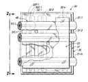
- FIG. 2is a vertical transverse sectional view or end view of the sensor array of FIG. 1 taken in the direction 2 - 2 .
- FIG. 3is a partly broken-away, upper perspective view of a second, two-layer embodiment of a piezoresistive thread pressure sensor array according to the invention, in which the central piezoresistive layer shown in the basic embodiment of FIGS. 1 and 2 is replaced by a piezoresistive coating on conductive threads of the sensor array.
- FIG. 4is a vertical transverse sectional or end view of the sensor array of FIG. 3 , taken in the direction 4 - 4 .
- FIG. 5is a fragmentary perspective view of a modification of the sensor array of FIGS. 1 and 3 in which adjacent pairs of more closely packed row and column conductor threads are spatially and electrically isolated from each other by non-conductive threads.
- FIG. 6Ais a fragmentary transverse sectional view of the sensor array of FIGS. 1 and 2 , on a further enlarged scale, showing the disposition of crossed row and column conductive threads contacting a central piezoresistive layer to form force sensing elements, with no external force applied to the elements.
- FIG. 6Bis a view similar to that of FIG. 6A , but with a moderate normal force applied to the sensor elements.
- FIG. 6Cshows the sensor elements with a larger external force applied thereto.
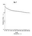
- FIG. 7is a graph showing electrical resistance plotted as a function of force or pressure exerted on sensor elements of the sensor arrays shown in FIGS. 1 and 3 .
- FIG. 8Ais a fragmentary transverse sectional view of the sensor array of FIGS. 3 and 4 on a further enlarged scale, showing the disposition of row and column piezoresistive threads to form force sensing elements, with no external force applied to the array.
- FIG. 8Bis a view similar to that of FIG. 8A , but with a moderate normal force applied to the sensor elements.
- FIG. 8Cshows the sensor element with a larger external force applied thereto.
- FIG. 9is a partly broken-away perspective view of a third, three-layer embodiment of a piezoresistive threads pressure sensor array according to the invention, which uses a pair of fabric outer substrates and a central piezoresistive layer.
- FIG. 10is a fragmentary view of the sensor array of FIG. 9 on an enlarged scale and showing a lower plan view of an upper, horizontal row conductor part of the sensor array.
- FIG. 11is a fragmentary view of the sensor array of FIG. 9 , on an enlarged scale and showing an upper plan view of a lower, vertical column conductor part of the sensor array.
- FIG. 12is a vertical transverse sectional view, of the sensor array of FIG. 9 , taken in the direction 12 - 12 .
- FIG. 13Ais a partly broken-away, exploded upper perspective view of a fourth, two-layer piezoresistive thread pressure sensor array using fabric substrates, according to the invention, in which the central piezoresistive layer of the embodiment shown in FIG. 9 is replaced by a piezoresistive coating on conductive threads of the sensor array.
- FIG. 13Bis a vertical transverse sectional view of the sensor array of FIG. 13A , taken in the direction 13 B- 13 B.
- FIG. 14is a partly broken-away upper perspective view of a fifth, single layer embodiment of a piezoresistive thread pressure sensor array according to the invention which has a single fabric substrate, in which both row and column piezoresistive threads are fastened to the same side of a single insulating substrate sheet.
- FIG. 15is an upper plan view of the sensor array of FIG. 14 .
- FIG. 16is a vertical transverse sectional view of the sensor array of FIG. 14 , taken in the direction 16 - 16 .
- FIG. 17is partly broken-away, exploded upper perspective view of a modification of the fabric substrate sensor arrays of FIG. 9 , 13 or 14 in which lower column conductive threads of the sensor array are disposed in a sinuous arrangement on the fabric lower substrate panel.
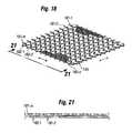
- FIG. 18is an upper perspective view of another modification of the single layer fabric substrate sensor array of FIG. 14 in which both the row and column conductive threads are sinuously arranged and located on opposite sides of a piezoresistive substrate sheet.
- FIG. 19is an upper plan view of the sensor array of FIG. 18 .
- FIG. 20is a lower plan view of the sensor array of FIG. 18 .
- FIG. 21is a vertical transverse sectional view of the sensor array of FIG. 19
- FIG. 21Ais a fragmentary upper perspective view of a single layer fabric substrate sensor array in which both upper row and lower column piezoresistive threads are sinuously arranged and fastened to the same side of a single insulating substrate sheet.
- FIG. 22Ais a schematic diagram showing the number of conductive lead-outs required to measure the resistance of individual sensor elements in a linear array.
- FIG. 22Bshows sensor elements which do not have to be in a linear arrangement.
- FIG. 23is a schematic diagram showing a reduced number of lead-outs required for matrix addressing an array of sensor elements arranged in a matrix array.
- FIG. 24is a schematic diagram showing sensor elements of the array of FIG. 23 modified to include a diode junction.
- FIG. 25is an upper perspective view of a force measuring sensor apparatus using two-layer sensor arrays of the type shown in FIG. 5 .
- FIG. 26is a block diagram showing the sensor array of FIGS. 1 and 3 interconnected with signal processing and display circuitry to comprise a force measurement system.
- FIG. 27Ais a perspective view of a sock incorporating the sensory array of FIG. 14-16 or 17 - 20 .
- FIG. 27Bis a horizontal transverse sectional view of the sock of FIG. 27A .
- FIG. 28is a typical electrical resistance-versus-normal force diagram for sensors according to the present invention.
- FIG. 29is a partly schematic view of a preferred modification of sensor elements of the array of FIG. 1 , in which sensor elements of the array have been modified to provide them with P-N, diode-type junctions.
- FIG. 30is a current-versus-voltage diagram for the sensor elements of FIG. 27 .
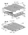
- FIG. 31is an exploded perspective view of another embodiment of a force sensor array according to the present invention.
- FIG. 32is a perspective view of the sensor array of FIG. 31 .
- FIG. 33is an exploded perspective view of components of another embodiment of a force sensor array according to the present invention.
- FIG. 34is a perspective view of the sensor array of FIG. 33 .
- FIGS. 1-34illustrate various aspects of elastically stretchable, conformable fabric force sensor arrays, and methods for making the arrays, according to the present invention.
- FIGS. 1 and 2a first, basic, three-layer embodiment of a force sensor array according to the present invention is shown.
- a three-layer force sensor array 30includes a plurality m of elongated, straight thin conductive row threads 31 - l through 31 - m and a plurality n of elongated, straight thin, conductive column threads 32 - l through 32 - n.
- the electrically conductive row threads 31 and column threads 32consist of an elastically stretchable monofilament or woven polymer core 31 C, 32 C, which has been treated to make the threads electrically conductive, as by silver plating the core to form coatings 31 P, 32 P on cores 31 C, 32 C, respectively.
- One type of example embodiment of a sensor array 30 according to the present inventionused row and column conductive threads 31 , 32 made from silver plated nylon thread, 117/17 2 ply, catalog #A264, obtained from LESS EMF, 809 Madison Avenue, Albany, N.Y. 12208, USA. That conductive thread had a lineal resistivity of about 75 ohms per foot, and an elastic stretchability of about 1 percent, i.e., at least 10 times greater than that of a stainless steel wire of a similar diameter.
- a second type of example embodiment of a sensor array according to the present inventionuses row and column conductive threads made from silver plated stretchy nylon yarn, that plated yarn having the designation Shieldex, ®Lycra dtex 20, obtained from W.Zimmerman, GmbH & Co. K6, Riederstrasse 7, D-88171, Roth-Simmerberg, Germany. That conductive thread had a lineal resistivity of about 500 ohms per foot.
- the elastic stretchability of that conductive yarnis greater than 30 percent, i.e., at least 300 times greater than that of a stainless steel wire of a similar diameter.
- a row threads 31 and column threads 32lie in parallel planes but are inclined with respect to one another, such as at an angle of ninety-degrees.
- row conductive threads 31are fastened to the lower surface 34 on an upper substrate sheet 33
- column conductive threads 32are fastened to the upper surface 36 of a lower substrate sheet 35 .
- sensor array 30includes a thin central lamination or sheet 37 made of a piezoresistive material.
- opposed inner facing outer surfaces 38 , 39 of row and column conductive threadstangentially contact upper and lower surfaces 40 , 41 , respectively, of central piezoresistive sheet 37 .
- each crossing point or intersection of a row conductive thread 31 and a column conductive thread 32forms a piezoresistive sensor element 48 which consists of a small portion of central piezoresistive sheet 37 that is electrically conductively contacted by a row conductive thread and a column conductive thread.
- piezoresistive sheet 37was fabricated by coating a stretchy,” i.e., elastically stretchable thin Lycra-like fabric sheet with a piezoresistive material.
- a suitable fabric sheet, which forms a matrix for supporting the piezoresistive materialwas a fabric known by the trade name Platinum, Milliken, Style #247579, obtained from the manufacturer, Milliken & Company, Spartenburg, S.C., USA. That fabric had a fiber content of 69 percent nylon and 31 percent Spandex, a thread count of about 88 threads per inch, and aa thickness of 0.010 inch.
- the piezoresistive material used to coat the fabric matrixis made as follows:
- a solution of graphite, carbon powder, nickel powder and acrylic binderare mixed in proportions as required to obtain the desired resistance and piezoresistive properties.
- Silver coated nickel flakeis used to achieve force response in the low force range of 0 to 1 psi
- graphiteis used for the mid range of 1 to 5 psi
- Charcoal Lamp Blackis used for high force range of 5 to 1000 psi.
- Example IIIfor forces in the range of 0-1000 psi
- the fabric matrix for piezoresistive sheet 37is submerged in the piezoresistive coating mixture. Excess material is rolled off and the sheet is hung and allowed to air dry.
- upper and lower substrate sheets 33 , 34are made of a thin, flexible insulating material, such as 0.002 inch thick polyurethane or polyvinyl chloride (PVC).
- the substrate sheets 33 , 34are made of an elastomeric material which has a relatively high degree of elastic stretchability, so that sensor array 30 is readily stretchable and conformable to the surface of an irregularly-shaped object.
- conductive threads 31 , 32should also be elastically stretchable to facilitate stretchability of sensor array 30 . This is because conductive threads 31 , 32 are affixed to substrate sheet 33 , 34 , respectively, by, for example, blobs of adhesive 42 , as shown in FIG. 2 .
- Piezoresistive sheet 37is also fixed to upper and lower substrate sheets 33 , 34 by blobs of glue 42 .
- FIGS. 6A-6Cillustrate how the arrangement of row and column conductive threads 31 , 32 , in combination with central piezoresistive layer 37 of sensor array 30 shown in FIGS. 1 and 2 , form individual force sensing elements 48 .
- Each force sensor element 48is located at the cross-over or intersection point 49 of a row conductive thread, e.g., 31 - 1 , 31 - 2 , . . . 31 - m , with a column conductive thread, e.g., 32 - 1 , 32 - 2 , . . . 32 - n , for a M ⁇ N matrix of sensor elements.
- individual sensor elementsmay be identified by the nomenclature 48 -XXX-YYY, where XXX denotes row number and YYY denotes column number.
- the electrical resistance between a row conductive thread 31 and column conductive thread 32which consists of the series resistance of upper contact region 43 , lower contact region 44 , and the effective resistance of piezoresistive material 45 of piezoresistive layer 37 between the upper and lower contact regions is relatively high.
- the relatively high resistanceresults from the fact that in this case, tangential contact regions 43 and 44 are relatively small, and the thickness of uncompressed piezoresistive volume 45 is at its maximum value.
- FIGS. 6B and 6Cillustrate the effects of increasing external normal forces or pressures exerted on sensor array 30 .
- sensor array 30is placed with its lower surface 46 supported on a surface S and a force N is exerted perpendicularly downwards on upper surface 47 of the array, resulting in a reaction force U being exerted upwardly by supporting surface S on lower surface 46 of the array.
- central piezoresistive layer 37is resiliently deformable, the compressive force on it decreases the thickness T of the part of the layer between a row conductive thread 31 and a column conductive thread 32 . This reduction in path length through piezoresistive layer 37 between a row conductive thread 31 and a column conductive thread 32 causes the electrical resistance R between the threads to decrease in value.
- FIG. 6BFor moderate values of normal force N, as shown in FIG. 6B , resilient deformation of central piezoresistive layer 37 is relatively small, resulting in a relative small reduction in electrical resistance R between the threads. Larger forces N exerted on sensor array 30 cause a larger deformation of the central piezoresistive layer, as shown in FIG. 6C , resulting in a larger percentage reduction in resistance R.
- FIG. 7illustrates in a general way the reduction in electrical resistance measurable between a row conductive thread 31 and a column conductive thread 32 , as a function of normal force or pressure exerted on array 30 at these points.
- FIGS. 3 and 4illustrate another embodiment 50 of a piezoresistive thread pressure sensor array according to the present invention, in which the central piezoresistive layer shown in FIGS. 1 and 2 and described above is replaced by a piezoresistive coating on either, or preferably both, row conductive threads 51 and column conductive threads 52 .
- Sensor array 50is facially similar to sensor array 20 disclosed and shown in FIGS. 1 and 2 of U.S. Pat. No. 6,543,299, but differs from that sensor array in important ways.
- row and column piezoresistive threads 51 , 52 of sensor array 50are made of elastically stretchable polymer cores 51 C, 52 C which have been treated by silver plating the cores to form on the threads electrically conductive coatings 51 P, 52 P, respectively.
- the coatings on either or both cores 51 C, 52 Care clad with a layer 51 R, 52 R, respectively, of a material which has a piezoresistive characteristic.
- the piezoresistive material used to form cladding layers 51 R, 52 R on plated surfaces 51 P, 52 P of cores 51 C, 52 C of piezoresistive conductive threads 51 , 52may have a composition similar to that described above for making piezoresistive sheet layer 37 .
- a method for making piezoresistive sensor threads by cladding conductive threads with a layer of a piezoresistive material according to the present inventionincludes preparing a slurry of piezoresistive material having a composition described in examples 1, 2 and 3 above.
- a highly conductive polymer threadsuch as silver plated nylon thread 117/17 2 play, Cat #124 available from LESS EMF Inc., 804 Madison Avenue, Albany, N.Y. 12208, is then immersed in a container holding the slurry, for a period of about 10 seconds. The end of a thread which has been immersed is withdrawn from the container, and while it is still wet, drawn through a circular aperture through a scraper plate.
- a conductive thread having a core diameter of 0.25 mm and wet-coated diameter in the range of about 0.4 mm to 0.5 mmwas drawn through a #360 scraper having a diameter of 0.45 mm, thus resulting in a wet scraped diameter of about 0.45 mm.
- the scraped threadwas then fed through a stream of air heated to a temperature of 70 degrees C. at a linear travel speed of 100 mm/minute for a period of 5 minutes, to thus form a solidified coating having a diameter of about 0.4 mm.
- piezoresistive row and column threads 51 , 52are fastened to upper and lower substrate sheets 63 , 65 , by suitable means such as adhesive blobs 74 .
- Substrate sheets 63 , 64are made of a thin, flexible material such as 0.003 inch thick elastomeric polyurethane or polyvinyl chloride (PVC) that has a relatively high degree of elasticity.
- FIGS. 3 and 8 A- 8 Cillustrate how the arrangement of row and column piezoresistive threads 51 , 52 of sensor array 50 form individual force sensing elements 69 .
- piezoresistive cladding layers 51 R, 52 R on row and column conductive core threads 51 C, 52 Care progressively compressed into oval cross-sectional shapes of smaller diameter.
- the electrical resistance of each sensor element 70decreases in inverse proportion to applied pressure, as shown in FIG. 7 .
- FIG. 5illustrates a modification 70 of the sensor arrays shown in FIGS. 1 and 3 and described above.
- Modified sensor array 70may alternatively employ the three-layer construction of sensor array 30 shown in FIG. 1 , or the two-layer construction of sensor array 50 shown in FIG. 3 .
- the modificationconsists of fabricating sensor array 70 with electrically insulating material between adjacent rows and/or columns of conductive threads.
- the modification 70 of two-layer sensor 50 shown in FIG. 3includes elongated insulating threads 71 , made for example of 0.012 inch diameter polyester disposed between each pair of adjacent row conductive threads 51 and each pair of adjacent column conductive threads 52 .
- the insulating threads 71are secured in place by any suitable means, such as adhesively bonding the threads to substrate sheets 63 , 65 (see FIGS. 2 and 4 ).
- This constructingenables sensor array 70 to be substantially wrinkled or otherwise deformed to conform to an irregularly shaped surface, without the possibility of pairs adjacent row or column conductive threads 51 or 52 contacting one another to thus cause an electrical short circuit which would result in erroneous sensor element resistance measurements and force determinations.
- insulation between adjacent pairs of row and column conductive threadscould be applied by lightly spraying an aerosol insulation acrylic paint to hold the conductive threads in place.
- FIGS. 9-12illustrate a three-layer embodiment 80 of a piezoresistive thread force sensor array according to the present invention.
- Sensor array 80is similar to the basic embodiment 30 of sensor array shown in FIGS. 1-2 and described above.
- sensor array 80uses upper and lower substrate sheets 83 , 85 which are made of woven fabric rather than polymer films. This construction, in conjunction with the use of stretchy conductive row and column threads 81 , 82 made of plated nylon or Lycra cores, results in a sensor array that is even more flexible, elastically stretchable and drapable than sensor array 30 .
- sensor array 80includes a plurality of parallel, laterally spaced apart conductive row threads 81 which are fastened to the lower surface 84 of upper fabric substrate sheet 83 .
- the row conductive threads 81are fastened to lower surface 84 of upper substrate sheet 83 by any suitable means.
- each row conductive thread 81is fastened to a substrate sheet by sewing the thread to fabric substrate sheet 83 by a smaller diameter, non-conductive thread 90 arranged in an elongated zig-zag stitching pattern.
- threads 90consisted of 0.005-0.010 inch diameter, 100% polyester woven thread.
- threads 90may optionally be monofilaments.
- upper and lower substrate sheets 83 , 85were made from a light-weight, elastically stretchable fabric, both of the two following fabrics were tested and found suitable for substrate sheets 83 , 85 .
- Both of the foregoing fabricsare available from Miliken & Company, 23 Fiddler's Way, Lafayette, N.J. 07848.
- lower column conductive threads 82are fastened to the upper surface 86 of lower fabric substrate sheet 85 by non-conductive threads 91 of the same type as non-conductive threads 90 and in the same zig-zag stitching manner.
- three-layer fabric substrate sensor array 80includes a central piezoresistive sheet 87 , which may have a composition and construction similar to that of central piezoresistive sheet 37 of sensor array 30 described above.
- upper, row piezoresistive threads 101are attached to lower surface 114 of upper fabric substrate sheet 113 by insulating sewn threads 90 arranged in zig-zag stitches.
- lower, column piezoresistive threads 102are attached to the upper surface 116 of lower substrate sheet 115 by sewn threads 91 arranged in zig-zag stitches.
- FIGS. 13A and 13Billustrate another two-layer embodiment 100 of a piezoresistive thread force sensor array according to the present invention.
- Sensor array 100is similar to sensor array 80 .
- conductive row and column threads 81 , 82are replaced by piezoresistive threads 101 , 102 which have the same characteristics as piezoresistive threads 51 , 52 of the two-layer polymer film substrate sensor array 50 shown in FIGS. 3 and 4 and described above.
- This constructioneliminates the requirement for the central piezoresistive sheet 87 of three-layer fabric sensor array 80 described above.
- FIGS. 14-16illustrate a fifth, single layer embodiment 120 of a force sensor array in which row and column piezoresistive threads are attached to a single side of a single insulating fabric substrate sheet 127 .
- single layer fabric force sensor array 120has a single substrate sheet 127 which is made from a light-weight, elastically stretchable fabric. Both of the two following fabric were listed and found suitable for making substrate sheet 127 .
- a plurality of parallel, laterally spaced apart column piezoresistive threads 122are fastened to the upper surface 130 of the substrate sheet.
- the column piezoresistive threadsare made from silver-plated nylon thread, Catalog #A-264 obtained from LESS EMF, or preferably from silver-plated stretchy nylon yarn, both of which are described in detail above in conjunction with the description of sensor array 30 .
- each column piezoresistive thread 122is fastened to substrate sheet 127 by a smaller diameter, non-conductive thread 91 arranged in an elongated zig-zag stitching pattern.
- threads 91consisted of 0.005-0.010 diameter, 100% polyester.
- sensor array 120includes a plurality of parallel, laterally spaced apart piezoresistive row threads 121 which are also fastened to the upper surface 130 of substrate sheet 127 .
- m row piezoresistive threads 121are fastened to substrate sheet 127 by non-conductive threads 90 of the same type as threads 91 and in the same zig-zag stitching manner.
- each crossing of a row piezoresistive thread 121 with a column piezoresistive thread 122forms a piezoresistive sensor element 138 which consists of a small portion of piezoresistive coatings of a row and column piezoresistive thread tangentially contacting one another.
- FIG. 17illustrates a modification of the force sensor arrays using fabric substrate sheets shown in FIG. 9 , 13 or 14 and described above.
- a lower fabric substrate sheet 145 of modified force sensor array 140has attached thereto lower, column conductive piezoresistive threads 142 which are sinuously curved with respect to parallel straight base lines between opposite ends of each thread, rather than lying directly on the base lines, as are the column conductive threads 82 of sensor array 80 shown in FIG. 11 .
- lower fabric substrate sheet 145is even more readily elastically stretchable in directions parallel to the column thread base lines because longitudinally spaced apart points on the fabric substrate sheet are not constrained to be at maximum lengths by the less elastically stretchable conductive threads.
- the stretchability of the column substrate sheet 145is limited only by its intrinsic stretchability since the arrangement of column conductive threads 142 allows them to conform readily to size of the substrate sheet by changing spacing between peaks and valleys of the sinuously curved conductive threads, i.e., altering the spatial wavelengths of the sinuous curves formed by threads.
- upper row piezoresistive threads 141may also be sinuously arranged in the same manner as lower column piezoresistive threads shown in FIG. 17 , to thus enhance elastic compliance, or stretchability, of sensor array 140 is in directions parallel to the row conductive threads as well as in directions .parallel to the column piezoresistive threads.
- either or both row and column conductive threads of three-layer sensor arrayssuch as those of the type shown in FIG. 1 may be sinuously arranged to provide enhanced uniaxial or biaxial stretchability.
- FIGS. 18-21illustrate another modification 180 of the single fabric substrate sheet sensor array 120 of FIG. 14 .
- Sensor array 180has upper, row conductive threads 181 and lower, column conductive threads 182 which are both sinuously arranged on opposite sides of a fabric piezoresistive central substrate sheet 187 . This construction gives array 180 greater elasticity in directions parallel to the column conductive threads 182 as well as in directions parallel to row conductive threads 181 .
- FIG. 21Aillustrates another modification 200 , which row and column piezoresistive threads 201 , 202 are both sinuously arranged and attached to the upper surface 211 of an insulating substrate sheet 210 , in the manner shown in FIG. 16 .
- FIG. 22Aillustrates the number of conductive leads required to measure the resistance of individual elements of a linear array of sensor elements, to thus determine numerical values of force or pressure exerted on each sensor element.
- a single common lead-out conductor Cis connected to a linear array of intersecting lead-out conductors Li through Ln to form a plurality of sensor elements SI through Sn, by piezoresistive material at each intersection point.
- n sensors Sthere are required a total R equal to n+1 lead-out conductors to measure the individual resistance of each sensor element SI through Sn and hence determine the forces F 1 through Fn exerted on each individual sensor element.
- FIG. 22Bshows a plurality of sensor elements Sn+1, Sn+2, Sn+3 which are not necessarily arranged in a linear array, being located, for example, on individual finger tips. As shown in FIG. 22B , n+1 lead-out conductors are also required for this configuration.
- FIG. 7illustrates the electrical resistance of a one-inch square piezoresistive force sensor element 48 using a piezoresistive sheet 37 having the formulation listed for an example sensor array 30 shown in FIGS. 1 and 2 , and fabricated as described above, as a function of normal force or pressure exerted on the upper surface 47 of upper substrate sheet 33 of sensor array 30 .
- the resistancevaries inversely as a function of normal force.
- row conductive threads 31 - 1 through 31 - min vertical alignment with column conductive threads 32 - 1 through 32 - n form with piezoresistive layer sheet 37 between the column and row conductive threads a m ⁇ n rectangular matrix array of m ⁇ n force elements 48 .
- each sensor element 48would be electrically isolated from connections to each other sensor element, a separate pair of lead-out conductors for each of the sensors, would be required, i.e., a total of 2Qlead-out conductors for Q sensor elements or, if a single common electrode lead-out were employed as shown in FIG. 22 , a total of Q+1 lead-outs would be required.
- FIG. 23if matrix addressing of sensor array 30 is used to measure the resistance of individual sensors 48 to thereby determine normal forces exerted on the sensors, there is a substantial cross-talk between the resistance on an addressed sensor 48 and non-selected sensors because of parallel current paths to non-addressed sensors.
- the present inventorhas developed a method for modifying sensors 48 to give them a diode-like characteristic. As may be confirmed by referring to FIG. 24 , the cross-talk between sensor elements 40 which have a non-bilateral, polarity-sensitive transfer function, mitigates the cross-talk problem present in the matrix of symmetrically conductive sensors 48 shown in FIG. 23 .
- Sensor elements 48are modified to have a diode-like characteristic by modifying the preparation of piezoresistive layer sheet 37 , as follows: First, a piezoresistive layer sheet 37 is prepared by the process described above. Then, either the upper surface 40 or the lower surface 41 of the piezoresistive coating 37 A of piezoresistive sheet 37 is modified to form thereon a P-N, semiconductor-type junction.
- Modification of piezoresistive coating 37 A to form a P-N junctionis performed by first preparing a slurry which has the composition of one of the three example mixtures described above, but modified by the addition of 5 ml each of copper oxide (CuO) in the form of a fine powder of 50-micron size particles, and 5 ml of cuprous oxide (Cu 2 O) in the form of a fine powder of 50-micron size particles and thoroughly stir-mixing the foregoing ingredients.
- the resultant solutionis then reduced using about 30 mg of solution of sodium borohydride, also known as sodium tetrahydroborate (NaBH 4 ) or ammonium phosphate, to form a solution having a pH of about 5.5.
- sodium borohydridealso known as sodium tetrahydroborate (NaBH 4 ) or ammonium phosphate
- the solutionis then coated onto the upper surface 40 or lower surface 41 of piezoresistive coating 37 B on piezoresistive sheet 37 .
- This coating processis performed using a roller coating process which results in about 0.5 ml of solution per square centimeters being applied.
- the surface coatingis then allowed to air-dry at room temperature and a relative humidity of less than 20%, for 4 hours. After the coated surface has dried, it functions as a P-type semiconductor, while the uncoated side of coating 37 B functions as an N-type semiconductor of P-N junction diode.
- FIG. 29illustrates a sensor element 48 which has been prepared as described above to give the sensor a diode-like characteristic, and a circuit for obtaining the I-V (current versus voltage) transfer function of the sensor.
- FIG. 30shows a typical I-V curve for sensor elements 48 of FIG. 29 .
- the advantage of modifying sensor elements 48 of sensor array 30 by adding a semi-conductive layer that acts like a diodeis that it reduces cross talk between sensors. As is shown in FIG. 23 , this cross-talk occurs because of the so-called “completing the square” phenomenon, in which three connections are made in a square matrix array of three non-addressed resistors that form the three corners of a square. Thus, any two connections in a vertical column and a third one in the same row function as either connection in an X-Y array of conductors.
- the resistor at the fourth corner of the squareshows up as a phantom in parallel with an addressed resistor because the current can travel backwards through that resistor, and forward through the other resistors.
- the measured value of R 11would be:
- each sensor element 48to include a p-n junction thereby give the sensor element a diode-like characteristic electrically isolates, i.e., prevents backward current flow, through each sensor element 48 .
- Thisenables the correct value of electrical resistance of each sensor element 48 and hence forces exerted thereon to be measured accurately R x1 y 1 using row and column matrix addressing rather than requiring a separate pair of conductors for each sensor element.
- FIG. 25illustrates a force measuring apparatus 150 according to the present invention.
- the apparatusmay use any of the types of sensor arrays described above, but in a particular example shown in FIG. 25 uses a sensor array 70 of the type shown in FIG. 5 .
- force measuring apparatus 150used four sensor arrays 70 - 1 , 70 - 2 , 70 - 3 and 70 - 4 , each having a matrix of 16 row conductive threads by 16 column conductive threads.
- FIG. 25force measuring apparatus 150 used four sensor arrays 70 - 1 , 70 - 2 , 70 - 3 and 70 - 4 , each having a matrix of 16 row conductive threads by 16 column conductive threads.
- each of the 32 row conductive thread lead-out wires and each of the 32 column conductive thread lead-outsis connected to a separate electrically conductive connector pin of a plurality of connector pins 154 - 1 through 154 - 64 of a pair of electrical interface connectors 153 - 1 , 153 - 2 .
- FIG. 26illustrates a force measurement system 160 which utilizes the force 6 sensor apparatus 150 described above.
- force measurement system 160includes a computer 161 which is bidirectionally coupled to force sensor array 70 of force sensor apparatus 160 through a force sensor interface module 162 .
- the sensor interface module 162includes a Digital-to-Analog Converter (DAC) 163 for generating in response to control signals from computer 161 test voltages or currents which are directed to matrix-addressed individual force sensors 88 .
- DACDigital-to-Analog Converter
- individual force sensor elements 88are addressed by connecting one terminal of a current or voltage source controlled by DAC 163 to a selected one of X-row conductors 51 - l - 51 - m by an X multiplexer 164 , and connecting the other terminal of the source to a selected one of Y-column conductors 52 - l - 52 - m by a Y multiplexer 165 .
- Sensor interface module 162also included an Analog-to-Digital Converter (ADC) 166 which measures the voltage drop or current through a sensor element 88 resulting from application of a test current or voltage, and inputs the measured value to computer 161 .
- ADCAnalog-to-Digital Converter
- computer 161calculates the instantaneous value of electrical resistance of a selected addressed sensor element 88 , and from that resistance value, a corresponding normal force instantaneously exerted on the addressed sensor.
- Measurement system 160includes an operator interface block 167 which enables values of force or pressures measured by sensor elements 88 to be displayed as numerical values and/or a graph or pressure/force map on the display screen of a computer monitor 168 , or outputted to a peripheral device such as a printer, or a network such as the internet, through an I/O block 169 .
- FIGS. 27A and 27Billustrate a sock 170 which includes one of the novel sensor arrays employing conductive threads which were described above, such as the single layer, fabric substrate piezoresistive thread sensor array shown in FIG. 14-16 or 17 - 20 .
- sock 170which includes a single layer fabric force sensor array 180 that is a modification of the planar force sensor array 120 shown in FIGS. 14-16 and described above.
- the modification of force sensor array 120 to form force sensor array 180may be best visualized by considering that the left and right side edges of the array 120 are brought upwards from the plane of the page to meet and form a hollow cylindrical tube.
- Row conductor threads protruding 121 from the aligned edges of the arrayare then electrically conductively fastened to a first, row conductor ribbon cable 181 .
- Column conductive threads protruding from one edge of the rolled-up arrayare electrically conductively fastened to a second, column conductor ribbon cable 182 .
- Outer ends 183 , 184 who protrude from an edge of array 120are electrically connected to a resistance measuring circuit as shown in FIG. 26 and described above.
- FIGS. 31-34illustrate modifications of fabric substrate force sensor arrays using conductive threads according to the present invention, in which the conductive threads are fixed to a fabric substrate sheet without the use of sewn stitching by adhesive applied directly to a conductive thread.
- a first, three-layer fabric sensor array 190includes a plurality of parallel, spaced apart row conductive elastic threads 191 which are adhesively bonded to the lower surface 194 of an upper stretchable fabric substrate sheet 193 made of 3 mil thick polyester or either of the two Milliken fabrics described above.
- Sensor array 190also includes a plurality of parallel spaced apart column conductive elastic threads 192 which are adhesively bonded to an upper surface 196 of a lower stretchable fabric substrate sheet 195 .
- a thin sheet of stretchable fabric prepared to give it a piezoresistive property in the manner described abovecomprises a central piezoresistive layer 197 which is positioned between row and column conductive threads 191 , 192 .
- the foregoing three layersare then stacked on top of one another and dots of glue injected through the mesh openings of the fabric substrate of all three layers to adhere them together and thus form a completed sensor array 190 .
- Sensor array 200utilizes a single substrate sheet 207 .
- Conductive row and column threads 191 , 192are adhered to upper surface 212 and lower surface 213 of sheet 207 by double-stick tape strips 213 , 214 .
Landscapes
- Physics & Mathematics (AREA)
- General Physics & Mathematics (AREA)
- Health & Medical Sciences (AREA)
- Life Sciences & Earth Sciences (AREA)
- Chemical & Material Sciences (AREA)
- Analytical Chemistry (AREA)
- Biochemistry (AREA)
- General Health & Medical Sciences (AREA)
- Immunology (AREA)
- Pathology (AREA)
- Force Measurement Appropriate To Specific Purposes (AREA)
Abstract
Description
- Platelets approximately one micron thick and 5 microns in diameter.
- Screen Analysis (−325 Mesh) 95%.
- Apparent Density 2.8.
- Microtrac d50/microns 12-17.
- Available from: Novamet Specialty Products Corporation,
- 681 Lawlins Road, Wyckoff, N.J. 07481
- Synthetic graphite, AC-4722T
- Available from: Anachemia Science
- 4-214 DeBaets Street
- Winnipeg, MB R2J 3W6
- Anachemia Part number AC-2155
- Available from: Anachemia Science
- 4-214 DeBaets Street
- Winnipeg, MB R2J 3W6
- Staticide Acrylic High Performance Floor Finish
- P/N 4000-1 Ph 8.4 to 9.0
- Available from: Static Specialties Co. Ltd.
- 1371-4 Church Street
- Bohemia, N.Y. 11716
- 200 ml of acrylic binder
- 10 ml of nickel flake powder
- 10 ml of graphite powder
- 20 ml of carbon black
- 200 ml of acrylic binder
- 5 ml of nickel flake powder
- 5 ml of graphite powder
- 30 ml of carbon black
- 200 ml of acrylic binder
- 1 ml of nickel flake powder
- 1 ml of graphite powder
- 40 ml of carbon black
Rx1y1=R11//(R12+[R22]+R21),Rx1y1=R11(R13+[R22]+R21)/(R11+R12+[R22]+R21),
where brackets around a resistance value indicate current flow in a counterclockwise direction through that resistor, rather than clockwise, i.e., diagonally downwards towards the left. Thus, for example, if each of the four resistances listed above had a value of 10 ohms, the measured value of R11would be:
Claims (38)
Priority Applications (13)
| Application Number | Priority Date | Filing Date | Title |
|---|---|---|---|
| US12/380,845US8161826B1 (en) | 2009-03-05 | 2009-03-05 | Elastically stretchable fabric force sensor arrays and methods of making |
| DK10749047.6TDK2404148T3 (en) | 2009-03-05 | 2010-03-03 | ROWS OF ELASTICALLY EXTENSIBLE FABRIC POWER SENSORS AND METHODS OF PRODUCING THEM |
| BRPI1009292ABRPI1009292A2 (en) | 2009-03-05 | 2010-03-03 | Elastic Stretchable Fabric Force Sensor Arrangements and Manufacturing Methods |
| CN2010800189615ACN102414546A (en) | 2009-03-05 | 2010-03-03 | Elastically stretchable fabric force sensor array and method of manufacture |
| AU2010221753AAU2010221753B9 (en) | 2009-03-05 | 2010-03-03 | Elastically stretchable fabric force sensor arrays and methods of making |
| ES10749047TES2703749T3 (en) | 2009-03-05 | 2010-03-03 | Elastic tensile fabric force sensor sets and manufacturing procedures |
| PCT/US2010/000645WO2010101633A2 (en) | 2009-03-05 | 2010-03-03 | Elastically stretchable fabric force sensor arrays and methods of making |
| CA2753535ACA2753535A1 (en) | 2009-03-05 | 2010-03-03 | Elastically stretchable fabric force sensor arrays and methods of making |
| EP10749047.6AEP2404148B1 (en) | 2009-03-05 | 2010-03-03 | Elastically stretchable fabric force sensor arrays and methods of making |
| JP2011552938AJP2012519846A (en) | 2009-03-05 | 2010-03-03 | Elastically stretchable fabric-like force sensor array and manufacturing method thereof |
| US13/453,461US8661915B2 (en) | 2009-03-05 | 2012-04-23 | Elastically stretchable fabric force sensor arrays and methods of making |
| US13/724,889US8800386B2 (en) | 2008-03-15 | 2012-12-21 | Force sensing sheet |
| US14/341,328US9642470B2 (en) | 2008-03-15 | 2014-07-25 | Force sensing sheet |
Applications Claiming Priority (1)
| Application Number | Priority Date | Filing Date | Title |
|---|---|---|---|
| US12/380,845US8161826B1 (en) | 2009-03-05 | 2009-03-05 | Elastically stretchable fabric force sensor arrays and methods of making |
Related Child Applications (2)
| Application Number | Title | Priority Date | Filing Date |
|---|---|---|---|
| US12/075,937ContinuationUS8533879B1 (en) | 2008-03-15 | 2008-03-15 | Adaptive cushion method and apparatus for minimizing force concentrations on a human body |
| US13/453,461ContinuationUS8661915B2 (en) | 2008-03-15 | 2012-04-23 | Elastically stretchable fabric force sensor arrays and methods of making |
Publications (1)
| Publication Number | Publication Date |
|---|---|
| US8161826B1true US8161826B1 (en) | 2012-04-24 |
Family
ID=42710152
Family Applications (4)
| Application Number | Title | Priority Date | Filing Date |
|---|---|---|---|
| US12/380,845Active2030-07-04US8161826B1 (en) | 2008-03-15 | 2009-03-05 | Elastically stretchable fabric force sensor arrays and methods of making |
| US13/453,461Active2029-04-15US8661915B2 (en) | 2008-03-15 | 2012-04-23 | Elastically stretchable fabric force sensor arrays and methods of making |
| US13/724,889ActiveUS8800386B2 (en) | 2008-03-15 | 2012-12-21 | Force sensing sheet |
| US14/341,328Active2029-06-20US9642470B2 (en) | 2008-03-15 | 2014-07-25 | Force sensing sheet |
Family Applications After (3)
| Application Number | Title | Priority Date | Filing Date |
|---|---|---|---|
| US13/453,461Active2029-04-15US8661915B2 (en) | 2008-03-15 | 2012-04-23 | Elastically stretchable fabric force sensor arrays and methods of making |
| US13/724,889ActiveUS8800386B2 (en) | 2008-03-15 | 2012-12-21 | Force sensing sheet |
| US14/341,328Active2029-06-20US9642470B2 (en) | 2008-03-15 | 2014-07-25 | Force sensing sheet |
Country Status (10)
| Country | Link |
|---|---|
| US (4) | US8161826B1 (en) |
| EP (1) | EP2404148B1 (en) |
| JP (1) | JP2012519846A (en) |
| CN (1) | CN102414546A (en) |
| AU (1) | AU2010221753B9 (en) |
| BR (1) | BRPI1009292A2 (en) |
| CA (1) | CA2753535A1 (en) |
| DK (1) | DK2404148T3 (en) |
| ES (1) | ES2703749T3 (en) |
| WO (1) | WO2010101633A2 (en) |
Cited By (102)
| Publication number | Priority date | Publication date | Assignee | Title |
|---|---|---|---|---|
| US20110140723A1 (en)* | 2009-12-10 | 2011-06-16 | Electronics And Telecommunications Research Institute | Seating sensing device and method of the same |
| US20110203390A1 (en)* | 2010-02-24 | 2011-08-25 | The Hong Kong Research Institute Of Textiles And Apparel Limited | Soft pressure sensing device |
| US20120053424A1 (en)* | 2010-08-24 | 2012-03-01 | Evacusled Inc. | Smart mattress |
| US20120091990A1 (en)* | 2010-10-19 | 2012-04-19 | Shohei Tsukada | Contact sensor, driver device, and care bed |
| US20120323501A1 (en)* | 2011-05-20 | 2012-12-20 | The Regents Of The University Of California | Fabric-based pressure sensor arrays and methods for data analysis |
| US20130160183A1 (en)* | 2011-12-23 | 2013-06-27 | Akseli Reho | Textile arrangement and method for manufacturing |
| US20130174345A1 (en)* | 2012-01-05 | 2013-07-11 | MyWellnessGuard Inc. | Occupant monitoring system |
| US20140026682A1 (en)* | 2012-07-27 | 2014-01-30 | Seda Chemical Products Co., Ltd. | Imperceptible motion sensing device having conductive elastomer |
| EP2702973A1 (en) | 2012-08-30 | 2014-03-05 | Hill-Rom Services, Inc. | Interface pressure sensing mattress |
| US20140130593A1 (en)* | 2012-11-13 | 2014-05-15 | Industrial Technology Research Institute | Pressure measurement structure |
| EP2745745A1 (en) | 2012-12-19 | 2014-06-25 | Stjernfjädrar AB | Bed with automatically adjustable properties |
| EP2762042A1 (en) | 2013-02-01 | 2014-08-06 | Stjernfjädrar AB | Bed having zones with adjustable height/firmness |
| US8884913B2 (en) | 2010-03-19 | 2014-11-11 | Smart Skin Technologies | Systems and methods for determining the location and pressure of a touchload applied to a touchpad |
| US20140331412A1 (en)* | 2008-03-15 | 2014-11-13 | Stryker Corporation | Force sensing sheet |
| US8904876B2 (en) | 2012-09-29 | 2014-12-09 | Stryker Corporation | Flexible piezocapacitive and piezoresistive force and pressure sensors |
| US8966997B2 (en) | 2011-10-12 | 2015-03-03 | Stryker Corporation | Pressure sensing mat |
| US8997588B2 (en) | 2012-09-29 | 2015-04-07 | Stryker Corporation | Force detecting mat with multiple sensor types |
| US20150280102A1 (en)* | 2012-10-12 | 2015-10-01 | Kansai University | Piezoelectric element |
| US20150292964A1 (en)* | 2012-10-08 | 2015-10-15 | Stc.Unm | Pliable Pressure-Sensing Fabric |
| US20150331512A1 (en)* | 2014-05-15 | 2015-11-19 | Bebop Sensors, Inc. | Promoting sensor isolation and performance in flexible sensor arrays |
| WO2016037172A1 (en)* | 2014-09-05 | 2016-03-10 | Lsi Solutions, Inc. | System and method for evaluating surgical knot formation |
| US9453774B2 (en) | 2013-12-17 | 2016-09-27 | The Board Of Trustees Of The Leland Stanford Junior University | Surface area-based pressure sensing |
| US20160327441A1 (en)* | 2014-12-24 | 2016-11-10 | Nippon Mektron, Ltd. | Pressure sensing element and pressure sensor |
| US9539155B2 (en) | 2012-10-26 | 2017-01-10 | Hill-Rom Services, Inc. | Control system for patient support apparatus |
| US9546921B2 (en) | 2009-10-16 | 2017-01-17 | Bebop Sensors, Inc. | Piezoresistive sensors and sensor arrays |
| US20170029985A1 (en)* | 2014-04-16 | 2017-02-02 | Teijin Limited | Transducer including fibers and outputting and inputting an electric signal |
| US20170036066A1 (en)* | 2015-08-05 | 2017-02-09 | Tony CHAHINE | Garment with stretch sensors |
| US9582035B2 (en) | 2014-02-25 | 2017-02-28 | Medibotics Llc | Wearable computing devices and methods for the wrist and/or forearm |
| US9582072B2 (en) | 2013-09-17 | 2017-02-28 | Medibotics Llc | Motion recognition clothing [TM] with flexible electromagnetic, light, or sonic energy pathways |
| US9588582B2 (en) | 2013-09-17 | 2017-03-07 | Medibotics Llc | Motion recognition clothing (TM) with two different sets of tubes spanning a body joint |
| US20170066136A1 (en)* | 2015-09-04 | 2017-03-09 | University Of Maryland | All-elastomer 3-axis contact resistive tactile sensor arrays and micromilled manufacturing methods thereof |
| US9625330B2 (en) | 2014-08-01 | 2017-04-18 | The Board Of Trustees Of The Leland Stanford Junior University | Methods and apparatus concerning multi-tactile sensitive (E-skin) pressure sensors |
| US9648915B2 (en) | 2012-10-06 | 2017-05-16 | James Edward Jennings | Smart fibre armor |
| US9652101B2 (en) | 2014-05-15 | 2017-05-16 | Bebop Sensors, Inc. | Two-dimensional sensor arrays |
| EP3171146A1 (en) | 2015-11-17 | 2017-05-24 | Eidgenössische Materialprüfungs- und Forschungsanstalt EMPA | Sandwich-like pressure sensitive sensor array |
| US9710060B2 (en) | 2014-06-09 | 2017-07-18 | BeBop Senors, Inc. | Sensor system integrated with a glove |
| US9721553B2 (en) | 2015-10-14 | 2017-08-01 | Bebop Sensors, Inc. | Sensor-based percussion device |
| US9753568B2 (en) | 2014-05-15 | 2017-09-05 | Bebop Sensors, Inc. | Flexible sensors and applications |
| US9827996B2 (en) | 2015-06-25 | 2017-11-28 | Bebop Sensors, Inc. | Sensor systems integrated with steering wheels |
| US9836151B2 (en) | 2012-03-14 | 2017-12-05 | Bebop Sensors, Inc. | Multi-touch pad controller |
| US9863823B2 (en) | 2015-02-27 | 2018-01-09 | Bebop Sensors, Inc. | Sensor systems integrated with footwear |
| US9875633B2 (en) | 2014-09-11 | 2018-01-23 | Hill-Rom Sas | Patient support apparatus |
| US9942979B2 (en) | 2014-11-03 | 2018-04-10 | Samsung Electronics Co., Ltd. | Flexible printed circuit board |
| US9949685B2 (en) | 2013-01-25 | 2018-04-24 | Howmedica Osteonics Corp. | Instrumented sleeve |
| US9955910B2 (en) | 2005-10-14 | 2018-05-01 | Aranz Healthcare Limited | Method of monitoring a surface feature and apparatus therefor |
| US9965076B2 (en) | 2014-05-15 | 2018-05-08 | Bebop Sensors, Inc. | Piezoresistive sensors and applications |
| US10013527B2 (en) | 2016-05-02 | 2018-07-03 | Aranz Healthcare Limited | Automatically assessing an anatomical surface feature and securely managing information related to the same |
| US20180266908A1 (en)* | 2014-12-18 | 2018-09-20 | Nitta Corporation | Sensor sheet |
| US10082381B2 (en) | 2015-04-30 | 2018-09-25 | Bebop Sensors, Inc. | Sensor systems integrated with vehicle tires |
| US20180325446A1 (en)* | 2017-05-12 | 2018-11-15 | Medicustek Inc. | Wearable physiological monitoring device |
| WO2018217585A1 (en)* | 2017-05-22 | 2018-11-29 | Apple Inc. | Multi-element piezo sensors for physiological measurements |
| US20190021650A1 (en)* | 2016-01-15 | 2019-01-24 | The Regents Of The University Of California | Systems and Methods for Monitoring a Patient |
| US10314492B2 (en) | 2013-05-23 | 2019-06-11 | Medibotics Llc | Wearable spectroscopic sensor to measure food consumption based on interaction between light and the human body |
| US10321873B2 (en) | 2013-09-17 | 2019-06-18 | Medibotics Llc | Smart clothing for ambulatory human motion capture |
| US10347815B1 (en)* | 2015-12-22 | 2019-07-09 | X Development Llc | Piezoelectric strands for tactile sensing |
| US10362989B2 (en) | 2014-06-09 | 2019-07-30 | Bebop Sensors, Inc. | Sensor system integrated with a glove |
| US10368799B2 (en) | 2015-01-27 | 2019-08-06 | Apple Inc. | System for determining the quality of sleep |
| US10386224B2 (en) | 2016-10-25 | 2019-08-20 | Studio 1 Labs Inc. | Flexible conductive apparatus and systems for detecting pressure |
| US10393599B2 (en) | 2014-10-16 | 2019-08-27 | Nokia Technologies Oy | Deformable apparatus and method |
| US20190271603A1 (en)* | 2018-03-05 | 2019-09-05 | Southern Taiwan University Of Science And Technology | Woven article and method for detecting stress distribution of woven article under stress |
| US10429888B2 (en) | 2014-02-25 | 2019-10-01 | Medibotics Llc | Wearable computer display devices for the forearm, wrist, and/or hand |
| US10435289B2 (en) | 2014-10-16 | 2019-10-08 | Nokia Technoloiges Oy | Deformable apparatus and method |
| US10512432B2 (en) | 2016-08-12 | 2019-12-24 | Apple Inc. | Vital signs monitoring system |
| US10568579B2 (en)* | 2015-04-02 | 2020-02-25 | Korea Institute Of Science And Technology | Pressure sensor including hybrid electronic sheet and wearable device including the pressure sensor |
| US10602965B2 (en) | 2013-09-17 | 2020-03-31 | Medibotics | Wearable deformable conductive sensors for human motion capture including trans-joint pitch, yaw, and roll |
| US10624249B1 (en)* | 2017-01-01 | 2020-04-14 | Andrea Zemberyová | Electromagnetic radiation shielding in garments |
| US20200180264A1 (en)* | 2017-04-19 | 2020-06-11 | University Of Delaware | Carbon nanotube based sensor |
| US10716510B2 (en) | 2013-09-17 | 2020-07-21 | Medibotics | Smart clothing with converging/diverging bend or stretch sensors for measuring body motion or configuration |
| US10722174B2 (en) | 2014-07-11 | 2020-07-28 | The Board Of Trustees Of The Leland Stanford Junior University | Skin-conformal sensors |
| US10758160B2 (en) | 2017-01-20 | 2020-09-01 | Figur8, Inc. | Body part motion analysis with wearable sensors |
| US10874302B2 (en) | 2011-11-28 | 2020-12-29 | Aranz Healthcare Limited | Handheld skin measuring or monitoring device |
| US10884496B2 (en) | 2018-07-05 | 2021-01-05 | Bebop Sensors, Inc. | One-size-fits-all data glove |
| WO2021071915A1 (en)* | 2019-10-08 | 2021-04-15 | Unlimited Tomorrow, Inc. | Biometric sensor array |
| US10989612B2 (en)* | 2014-03-31 | 2021-04-27 | Institut Francais Des Sciences Et Technologies Des Transport, De L'amenagement Et Des Reseaux | Sensor with a plurality of acquisition devices that measure force using impedance |
| CN113147648A (en)* | 2021-03-03 | 2021-07-23 | 西华大学 | Dot-matrix airbag popping judgment system and judgment method for unmanned vehicle |
| US11116407B2 (en) | 2016-11-17 | 2021-09-14 | Aranz Healthcare Limited | Anatomical surface assessment methods, devices and systems |
| US20210285837A1 (en)* | 2020-03-16 | 2021-09-16 | TE Connectivity Services Gmbh | Compressible Element For A Sensor Assembly |
| US11150147B2 (en)* | 2016-04-04 | 2021-10-19 | Pilz Gmbh & Co. Kg | Woven fabric having a plurality of woven fabric layers |
| US11173274B2 (en) | 2018-05-01 | 2021-11-16 | Bryte, Inc. | Sleeper detection and configuration of sleep environments and learning methods to optimize sleep quality |
| US11172892B2 (en) | 2017-01-04 | 2021-11-16 | Hill-Rom Services, Inc. | Patient support apparatus having vital signs monitoring and alerting |
| US20210356339A1 (en)* | 2020-05-14 | 2021-11-18 | Medx Technology Inc. | Fabric strain gauge, fabric pressure gauge and smart clothing |
| US20210372866A1 (en)* | 2020-05-28 | 2021-12-02 | Nano And Advanced Materials Institute Limited | Flexible pressure sensor array and method for fabrciating the same |
| US20220026296A1 (en)* | 2020-07-27 | 2022-01-27 | Tronics MEMS, Inc. | Flexible two-dimensional sheet array of electronic sensor devices |
| US11262873B2 (en)* | 2018-10-22 | 2022-03-01 | Google Llc | Conductive fibers with custom placement conformal to embroidered patterns |
| US20220066441A1 (en)* | 2020-08-28 | 2022-03-03 | Board Of Trustees Of Michigan State University | Flexible sensor |
| US20220163415A1 (en)* | 2020-11-24 | 2022-05-26 | Universal Cement Corporation | Piezosensitive Sensor Having Criss-Crossed Electrodes |
| US11351335B2 (en) | 2018-05-01 | 2022-06-07 | Bryte, Inc. | Sleep phase dependent pressure control and learning methods to optimize sleep quality |
| US11369207B2 (en) | 2016-07-29 | 2022-06-28 | Bryte, Inc. | Adaptive sleep system using data analytics and learning techniques to improve individual sleep conditions based on a therapy profile |
| US11385083B2 (en)* | 2018-12-07 | 2022-07-12 | Mohammad Kabany | Method for measuring and/or processing measured pressure and/or humidity values |
| US11412609B2 (en)* | 2018-05-08 | 2022-08-09 | W. L. Gore & Associates, Inc. | Flexible and stretchable printed circuits on stretchable substrates |
| US20220273115A1 (en)* | 2021-03-01 | 2022-09-01 | Sleep Number Corporation | Bed sensors |
| US11480481B2 (en) | 2019-03-13 | 2022-10-25 | Bebop Sensors, Inc. | Alignment mechanisms sensor systems employing piezoresistive materials |
| US11503918B2 (en) | 2018-05-01 | 2022-11-22 | Bryte, Inc. | Sleep phase dependent temperature control and learning methods to optimize sleep quality |
| US20230221193A1 (en)* | 2022-01-10 | 2023-07-13 | Wellsense, Inc. | Anti-crinkling pressure sensing mat |
| US20230218233A1 (en)* | 2022-01-10 | 2023-07-13 | Wellsense, Inc. | Pressure sensing mat with vent holes |
| US11717182B2 (en) | 2017-08-25 | 2023-08-08 | Mayo Foundation For Medical Education And Research | Abdominal measurement apparatuses and related methods |
| US11772760B2 (en) | 2020-12-11 | 2023-10-03 | William T. Myslinski | Smart wetsuit, surfboard and backpack system |
| US20240044729A1 (en)* | 2020-12-22 | 2024-02-08 | MAX-PLANCK-Gesellschaft zur Förderung der Wissenschaften e.V. | System and Method for Simultaneously Sensing Contact Force and Lateral Strain |
| US11903723B2 (en) | 2017-04-04 | 2024-02-20 | Aranz Healthcare Limited | Anatomical surface assessment methods, devices and systems |
| US11999864B2 (en) | 2020-01-30 | 2024-06-04 | Liquid X Printed Metals, Inc. | Molecular ink and method for printing resistive film coatings |
| US12039726B2 (en) | 2019-05-20 | 2024-07-16 | Aranz Healthcare Limited | Automated or partially automated anatomical surface assessment methods, devices and systems |
| US20240268558A1 (en)* | 2021-06-15 | 2024-08-15 | Tarta Design S.R.L. | Padding for support devices |
Families Citing this family (134)
| Publication number | Priority date | Publication date | Assignee | Title |
|---|---|---|---|---|
| US10512575B2 (en)* | 2007-02-06 | 2019-12-24 | Deka Products Limited Partnership | Dynamic support apparatus |
| EP2185070A1 (en)* | 2007-08-22 | 2010-05-19 | Commonwealth Scientific And Industrial Research Organisation | A system, garment and method |
| US8366692B2 (en) | 2008-01-08 | 2013-02-05 | Richard Scott Weston | Sustained variable negative pressure wound treatment and method of controlling same |
| AU2009223037A1 (en) | 2008-03-12 | 2009-09-17 | Smith & Nephew Plc | Negative pressure dressing and method of using same |
| WO2012170412A2 (en)* | 2011-06-07 | 2012-12-13 | Nanocomposites Inc. | Force sensing device and methods for preparing and uses thereof |
| KR101326796B1 (en) | 2012-01-10 | 2013-11-11 | 상명대학교서울산학협력단 | Textile touch sensor |
| CN104219999A (en)* | 2012-01-30 | 2014-12-17 | 感官系统公司 | Sensors, interfaces and sensor systems for data collection and integrated remote monitoring of conditions at or near body surfaces |
| JP5871129B2 (en)* | 2012-02-13 | 2016-03-01 | 日産自動車株式会社 | Cloth pressure sensor |
| JP2015521303A (en)* | 2012-03-30 | 2015-07-27 | ザ ボード オブ トラスティーズ オブ ザ ユニヴァーシ | An electronic device that can be attached to the surface and can be attached to an accessory |
| ES2981310T3 (en)* | 2012-05-30 | 2024-10-08 | Abena Holding As | System and method for detecting fluids in a diaper |
| ES2437718B1 (en)* | 2012-07-04 | 2014-08-27 | Sensing Tex, S.L. | Large area extensible pressure sensor for textile surfaces |
| EP3235426A3 (en) | 2012-10-15 | 2018-02-21 | Jordan Neuroscience, Inc. | Wireless eeg unit |
| GB201317746D0 (en) | 2013-10-08 | 2013-11-20 | Smith & Nephew | PH indicator |
| WO2014117724A1 (en)* | 2013-01-29 | 2014-08-07 | 中国科学院苏州纳米技术与纳米仿生研究所 | Electronic skin, preparation method and use thereof |
| US20140243709A1 (en)* | 2013-02-28 | 2014-08-28 | Hill-Rom Services, Inc. | Pressure Sensing Pad, Method of Making the Same, Pressure Sensing System, and Pressure Map Display |
| WO2014204323A1 (en)* | 2013-06-17 | 2014-12-24 | Stretchsense Limited | Stretchable fabric sensors |
| EP3013166B1 (en) | 2013-06-26 | 2018-02-07 | IMEC vzw | Methods for electrically connecting textile integrated conductive yarns |
| WO2015014950A1 (en)* | 2013-07-31 | 2015-02-05 | Universita' Degli Studi Di Cagliari | Textile pressure sensor and method for fabricating the same |
| CN104764412B (en)* | 2014-01-06 | 2019-04-05 | 中国计量学院 | Two-dimensional strain flexible high temperature fiber-optic grating sensor based on braiding structure |
| WO2015175317A1 (en)* | 2014-05-15 | 2015-11-19 | Bebop Sensors, Inc. | Piezoresistive sensors and applications |
| DE102014008446A1 (en)* | 2014-06-06 | 2015-12-17 | Fresenius Medical Care Deutschland Gmbh | Device for non-invasive measurement of blood flow |
| US10750997B2 (en) | 2014-07-09 | 2020-08-25 | Suunto Oy | Biometric sensor package for integration with a garment |
| US11684163B2 (en)* | 2014-08-27 | 2023-06-27 | Dewertokin Technology Group Co., Ltd | Electromotive furniture drive, and item of functional furniture having an electromotive furniture drive |
| JP6383919B2 (en)* | 2014-10-31 | 2018-09-05 | 国立大学法人鳥取大学 | Flat pressure sensor |
| US10945663B2 (en) | 2014-11-04 | 2021-03-16 | North Carolina State University | Smart sensing systems and related methods |
| JP7055965B2 (en) | 2014-12-30 | 2022-04-19 | スリーエム イノベイティブ プロパティズ カンパニー | Electrical conductor |
| KR101722064B1 (en)* | 2015-02-25 | 2017-03-31 | 한국패션산업연구원 | Stretchable strain sensor and sensing methode of vital siganl by using the same |
| WO2016146889A1 (en)* | 2015-03-13 | 2016-09-22 | Emfit Oy | Mattress for resting or sleeping of a person |
| US10248241B2 (en)* | 2015-05-07 | 2019-04-02 | Ricoh Company, Ltd. | Digital signage system |
| US9836118B2 (en) | 2015-06-16 | 2017-12-05 | Wilson Steele | Method and system for analyzing a movement of a person |
| CN105054953A (en)* | 2015-07-28 | 2015-11-18 | 安徽机电职业技术学院 | Clinical treatment effect evaluation system based on sole pressure distribution |
| CN108139282B (en)* | 2015-07-29 | 2020-10-16 | 小利兰·斯坦福大学托管委员会 | Method and apparatus relating to a sensitive force sensor |
| US10067007B2 (en) | 2015-09-02 | 2018-09-04 | Oculus Vr, Llc | Resistive-capacitive deformation sensor |
| KR102432009B1 (en)* | 2015-09-03 | 2022-08-12 | 엘지이노텍 주식회사 | Pressure sensor |
| CA2996886A1 (en)* | 2015-09-15 | 2017-03-23 | Sencorables Llc | Floor contact sensor system and methods for using same |
| US10416031B2 (en)* | 2015-09-25 | 2019-09-17 | MedicusTek, Inc. | Pressure sensing device |
| WO2017061799A1 (en)* | 2015-10-06 | 2017-04-13 | 엘지이노텍 주식회사 | Pressure-sensing chair |
| JP6675285B2 (en)* | 2016-08-15 | 2020-04-01 | 日本発條株式会社 | Load sensor, load detection device and seat for seating |
| WO2017065283A1 (en)* | 2015-10-15 | 2017-04-20 | 日本発條株式会社 | Load sensor, load detecting device and seat for sitting |
| JP6570007B2 (en)* | 2015-10-29 | 2019-09-04 | 国立大学法人鳥取大学 | Pressure sensor, surgical instrument and surgical device |
| KR102404474B1 (en)* | 2015-11-27 | 2022-06-07 | 한국재료연구원 | Textile sensor array structure, textile structure and devices comprising the same, and sensing metod using the same |
| US9816799B2 (en) | 2015-12-18 | 2017-11-14 | Oculus Vr, Llc | Embroidered strain sensing elements |
| US9817439B2 (en) | 2016-02-29 | 2017-11-14 | JumpStartCSR, Inc. | System, method and device for designing, manufacturing, and monitoring custom human-interfacing devices |
| US10054503B2 (en)* | 2016-03-11 | 2018-08-21 | Microsoft Technology Licensing, Llc | Force sensor |
| DE102016104725B4 (en) | 2016-03-15 | 2019-01-17 | Technische Hochschule Köln | A method of monitoring the structure of a fiber reinforced composite having a sensor array of a plurality of sensors for structure monitoring of the composite |
| US10470674B2 (en)* | 2016-03-17 | 2019-11-12 | Intel Corporation | Technologies for a fabric acoustic sensor |
| DE102016106071A1 (en)* | 2016-04-04 | 2017-10-05 | Pilz Gmbh & Co. Kg | Tissue with multiple layers of fabric and process for its preparation |
| CN105841601B (en)* | 2016-04-26 | 2019-04-23 | 清华大学 | A kind of fabric-based flexible wearable strain sensor and preparation method |
| KR101841827B1 (en) | 2016-05-12 | 2018-03-23 | 금호타이어 주식회사 | Intelligent Tire with Smart Wearable Sensors |
| CA3023772A1 (en) | 2016-05-13 | 2017-11-16 | Smith & Nephew Plc | Sensor enabled wound monitoring and therapy apparatus |
| US10314528B2 (en)* | 2016-05-20 | 2019-06-11 | American Sterilizer Company | Patient support pad |
| CN106092389A (en)* | 2016-05-27 | 2016-11-09 | 电子科技大学 | A kind of novel array-type flexible pressure transducer |
| US10473539B2 (en)* | 2016-06-30 | 2019-11-12 | Tekscan, Inc. | Stretchable force sensor having undulating patterned electrodes |
| WO2018044227A1 (en)* | 2016-06-30 | 2018-03-08 | Yoggzee Corporation Pte Ltd | Stretchable pressure mapping sysytem |
| US10918187B2 (en)* | 2016-07-20 | 2021-02-16 | Zen Design Solutions Limited | Cosmetic case |
| CN106289591B (en)* | 2016-08-09 | 2022-03-11 | 浙江大学昆山创新中心 | Involute type flexible capacitive pressure sensor and preparation method thereof |
| US10401239B2 (en)* | 2016-11-01 | 2019-09-03 | The Boeing Company | Integrated hyper-redundant tactile sensor network based on structural fibers |
| WO2018128583A1 (en)* | 2017-01-04 | 2018-07-12 | Mas Innovation (Private) Limited | Wearable touch button assembly |
| KR101997327B1 (en)* | 2017-01-16 | 2019-07-08 | 국민대학교산학협력단 | Resistance-switching stretch sensor including knitted conductive fibers |
| DE102017100786B4 (en)* | 2017-01-17 | 2018-09-06 | Pilz Gmbh & Co. Kg | Tactile sensor with housing |
| DE102017100791B4 (en)* | 2017-01-17 | 2018-09-06 | Pilz Gmbh & Co. Kg | Multi-layer, tactile sensor with fastening means |
| EP3592230A1 (en) | 2017-03-09 | 2020-01-15 | Smith & Nephew PLC | Apparatus and method for imaging blood in a target region of tissue |
| JP7091356B2 (en) | 2017-03-09 | 2022-06-27 | スミス アンド ネフュー ピーエルシー | Devices, devices, and methods for determining skin perfusion pressure |
| US11690570B2 (en) | 2017-03-09 | 2023-07-04 | Smith & Nephew Plc | Wound dressing, patch member and method of sensing one or more wound parameters |
| US11083652B2 (en) | 2017-04-03 | 2021-08-10 | United States Government As Represented By The Department Of Veterans Affairs | Smart foot position sensor for power wheelchair users, and systems and methods of using same |
| CA3059516A1 (en) | 2017-04-11 | 2018-10-18 | Smith & Nephew Plc | Component positioning and stress relief for sensor enabled wound dressings |
| DE102017109487B4 (en)* | 2017-05-03 | 2021-09-23 | Pilz Gmbh & Co. Kg | Multi-layer, tactile sensor |
| FI11690U1 (en)* | 2017-05-05 | 2017-06-09 | Valmet Technologies Oy | Measurement block for a fiber web machine |
| AU2018269112B2 (en) | 2017-05-15 | 2024-05-02 | Smith & Nephew Plc | Wound analysis device and method |
| EP3635733A1 (en) | 2017-05-15 | 2020-04-15 | Smith & Nephew plc | Negative pressure wound therapy system using eulerian video magnification |
| EP3632304A4 (en)* | 2017-05-29 | 2021-03-03 | Toyobo Co., Ltd. | BIOMETRIC INFORMATION MEASUREMENT CLOTHING |
| US10180721B2 (en)* | 2017-06-14 | 2019-01-15 | Apple Inc. | Fabric-based devices with force sensing |
| JP7189159B2 (en) | 2017-06-23 | 2022-12-13 | スミス アンド ネフュー ピーエルシー | Sensor placement for sensor-enabled wound monitoring or therapy |
| GB201809007D0 (en) | 2018-06-01 | 2018-07-18 | Smith & Nephew | Restriction of sensor-monitored region for sensor-enabled wound dressings |
| GB201804502D0 (en) | 2018-03-21 | 2018-05-02 | Smith & Nephew | Biocompatible encapsulation and component stress relief for sensor enabled negative pressure wound therapy dressings |
| SG11202000913XA (en) | 2017-08-10 | 2020-02-27 | Smith & Nephew | Positioning of sensors for sensor enabled wound monitoring or therapy |
| CN111093477B (en) | 2017-09-10 | 2023-09-12 | 史密夫及内修公开有限公司 | Systems and methods for inspecting packages and components in sensor-equipped wound dressings |
| GB201804971D0 (en) | 2018-03-28 | 2018-05-09 | Smith & Nephew | Electrostatic discharge protection for sensors in wound therapy |
| GB201718870D0 (en) | 2017-11-15 | 2017-12-27 | Smith & Nephew Inc | Sensor enabled wound therapy dressings and systems |
| CN107560768A (en)* | 2017-09-26 | 2018-01-09 | 浙江理工大学 | A kind of curved surface pressure sensor device based on fibre reinforced composites |
| GB201718859D0 (en) | 2017-11-15 | 2017-12-27 | Smith & Nephew | Sensor positioning for sensor enabled wound therapy dressings and systems |
| WO2019063481A1 (en) | 2017-09-27 | 2019-04-04 | Smith & Nephew Plc | Ph sensing for sensor enabled negative pressure wound monitoring and therapy apparatuses |
| WO2019072531A1 (en) | 2017-09-28 | 2019-04-18 | Smith & Nephew Plc | Neurostimulation and monitoring using sensor enabled wound monitoring and therapy apparatus |
| US11559438B2 (en) | 2017-11-15 | 2023-01-24 | Smith & Nephew Plc | Integrated sensor enabled wound monitoring and/or therapy dressings and systems |
| KR102021035B1 (en)* | 2017-11-28 | 2019-09-11 | 울산과학기술원 | Load cell |
| KR101998322B1 (en)* | 2017-11-28 | 2019-07-09 | 울산과학기술원 | Load cell and load cell array comprising the same |
| US11134789B2 (en)* | 2018-01-08 | 2021-10-05 | Dreamwell, Ltd. | Active comfort controlled bedding systems |
| CN110612437A (en)* | 2018-02-28 | 2019-12-24 | 住友理工株式会社 | Sensor electrode and planar sensor using same |
| US10325472B1 (en) | 2018-03-16 | 2019-06-18 | Palarum Llc | Mount for a patient monitoring device |
| WO2019200487A1 (en)* | 2018-04-19 | 2019-10-24 | Peyman Servati | Methods of and systems for estimating a topography of at least two parts of a body |
| CN110403592B (en)* | 2018-04-28 | 2022-03-29 | 五邑大学 | Wrist strap type heart rate meter |
| CN110411626B (en)* | 2018-04-28 | 2021-05-11 | 五邑大学 | A dynamometer based on cross structure |
| TR201808005A2 (en)* | 2018-06-05 | 2018-06-21 | Zeynep Akcasiz | WEARABLE TEXTILE USED FOR DIAGNOSIS OF BREAST CANCER AT HOME |
| RU2698073C1 (en)* | 2018-08-08 | 2019-08-21 | Федеральное государственное бюджетное образовательное учреждение высшего образования "Волгоградский государственный технический университет" (ВолгГТУ) | Sensitive element |
| CN109307565A (en)* | 2018-08-21 | 2019-02-05 | 厦门大学 | A flexible electronic skin capable of sensing pressure and preparation method thereof |
| GB201814011D0 (en) | 2018-08-29 | 2018-10-10 | Smith & Nephew | Componet positioning and encapsulation for sensor enabled wound dressings |
| EP3849401A1 (en) | 2018-09-12 | 2021-07-21 | Smith & Nephew plc | Device, apparatus and method of determining skin perfusion pressure |
| WO2020064937A1 (en) | 2018-09-28 | 2020-04-02 | T.J.Smith And Nephew,Limited | Optical fibers for optically sensing through wound dressings |
| GB201816838D0 (en) | 2018-10-16 | 2018-11-28 | Smith & Nephew | Systems and method for applying biocompatible encapsulation to sensor enabled wound monitoring and therapy dressings |
| WO2020079995A1 (en)* | 2018-10-18 | 2020-04-23 | パナソニックIpマネジメント株式会社 | Pressure-sensitive element and electronic equipment |
| WO2020081908A1 (en)* | 2018-10-18 | 2020-04-23 | Unisoft Medical Corporation | Cell bladder, expandable bladder, port system and attachment system |
| KR102268310B1 (en)* | 2019-05-13 | 2021-06-23 | 중앙대학교 산학협력단 | Fabric type multi sensor sheet |
| MX2021006276A (en) | 2018-11-29 | 2021-10-13 | Grote Industries Inc | INTELLIGENT CABLE SYSTEM FOR A TRUCK TRAILER. |
| GB201820927D0 (en) | 2018-12-21 | 2019-02-06 | Smith & Nephew | Wound therapy systems and methods with supercapacitors |
| WO2020172763A1 (en)* | 2019-02-25 | 2020-09-03 | 原见精机股份有限公司 | Force sensing device, force array sensing module and force sensing element thereof |
| JP7529681B2 (en) | 2019-03-18 | 2024-08-06 | スミス アンド ネフュー ピーエルシー | Design rules for sensor integrated boards |
| WO2020243610A1 (en)* | 2019-05-31 | 2020-12-03 | Mat Ipsum LLC | Earth ground enhancing systems |
| EP3980739A4 (en)* | 2019-06-05 | 2023-05-10 | Liquid Wire Inc. | DEFORMABLE SENSORS WITH SELECTIVE MOUNTING |
| CN112082675B (en)* | 2019-06-14 | 2022-01-18 | 武汉纺织大学 | Elastic array pressure sensor |
| TWI723467B (en)* | 2019-07-18 | 2021-04-01 | 美宸科技股份有限公司 | Pressure sensing device and manufacturing method thereof |
| US11460362B2 (en)* | 2019-07-23 | 2022-10-04 | Toyota Motor Engineering & Manufacturing North America, Inc. | Flexible printed pressure transducer with sensor diffusion stack materials and methods incorporating the same |
| GB201910563D0 (en) | 2019-07-24 | 2019-09-04 | Hussein Zakareya Elmo | A compliant tri-axial force sensor and method of fabricating the same |
| DE102019120191B3 (en) | 2019-07-25 | 2020-12-24 | Deutsche Institute Für Textil- Und Faserforschung Denkendorf | Embroidered sensor |
| CN110438829B (en)* | 2019-07-31 | 2021-07-30 | 太仓碧奇新材料研发有限公司 | Preparation method of composite conductive polymer flexible sensing array |
| GB201914443D0 (en) | 2019-10-07 | 2019-11-20 | Smith & Nephew | Sensor enabled negative pressure wound monitoring apparatus with different impedances inks |
| KR102237664B1 (en)* | 2019-10-16 | 2021-04-08 | 한국생산기술연구원 | Conductive fiber for pressure sensors with a signal transmissive yarn and manufacturing method therefor |
| CN110907501A (en)* | 2019-12-10 | 2020-03-24 | 新余学院 | Flexible stretchable temperature/humidity sensor insensitive to strain and preparation method thereof |
| KR102338298B1 (en)* | 2020-01-08 | 2021-12-13 | 한국전자기술연구원 | Conductive Thread based Pressure Sensor |
| BR112022015840A2 (en)* | 2020-02-18 | 2022-09-27 | Jk Holding Gmbh | STRUCTURE FOR THERAPEUTIC APPLICATIONS, CARPET, HYDROMASSAGE DEVICE WITH A MOBILE JET AND METHODS |
| US12232864B2 (en)* | 2020-04-09 | 2025-02-25 | Massachusetts Institute Of Technology | Systems and methods for estimating 3D position and movement from tactile signals |
| EP4139904A1 (en) | 2020-04-21 | 2023-03-01 | T.J. Smith and Nephew, Limited | Wound treatment management using augmented reality overlay |
| EP3936030B1 (en)* | 2020-07-07 | 2025-10-01 | von Lilienfeld-Toal, Sophie | Non-invasive blood pressure monitor |
| CN112515326A (en)* | 2020-12-02 | 2021-03-19 | 王铭衡 | Backpack with point-contact-type wearable pressure sensor |
| EP4269673A4 (en)* | 2020-12-23 | 2024-07-10 | Asahi Kasei Advance Corporation | SENSOR FIBER ELEMENT |
| US11796401B2 (en)* | 2021-04-07 | 2023-10-24 | Nano And Advanced Materials Institute Limited | Textile pressure sensor array and pressure distribution mapping system |
| US20220332513A1 (en)* | 2021-04-19 | 2022-10-20 | Flexible Steel Lacing Company | Carryback assessment mat |
| CN113358248B (en)* | 2021-06-11 | 2022-09-30 | 中国科学技术大学 | A fabric-type tension sensor array, driving method and smart object |
| WO2023052497A1 (en)* | 2021-09-30 | 2023-04-06 | Karma Technologies Ag | Method and pressure sensor unit |
| US11993498B2 (en)* | 2021-10-28 | 2024-05-28 | Toyota Research Institute, Inc. | Structures and sensor assemblies having engagement structures for securing a compliant substrate assembly |
| CN118829856A (en)* | 2022-03-18 | 2024-10-22 | 乐耐莎科技有限责任公司 | Systems, methods and apparatus for detecting pressure on a surface |
| WO2023249634A1 (en)* | 2022-06-24 | 2023-12-28 | Piana Nonwovens, Llc | Nonwoven smart cushion with in-place functionalized pressure sensing and thermoplastic heat sealed multi-region measurement coupling |
| DE102022122870A1 (en)* | 2022-09-08 | 2024-03-14 | Bellicon Ag | Jumping mat arrangement |
| CN115574705B (en)* | 2022-09-26 | 2025-04-25 | 沈阳飞机工业(集团)有限公司 | Aircraft panel assembly deformation monitoring method based on smart surface |
| US12178725B1 (en) | 2024-01-16 | 2024-12-31 | Vessl Prosthetics Inc. | Self-adjusting socket for lower limb prosthesis |
Citations (154)
| Publication number | Priority date | Publication date | Assignee | Title |
|---|---|---|---|---|
| US3818756A (en) | 1971-09-07 | 1974-06-25 | E Barron | Load profile analyzer in the attached specification |
| US3996922A (en) | 1973-08-17 | 1976-12-14 | Electronic Monitors, Inc. | Flexible force responsive transducer |
| US4033332A (en) | 1972-09-11 | 1977-07-05 | Cavitron Corporation | Activity and respiration monitor |
| US4267728A (en) | 1978-07-04 | 1981-05-19 | Manley Michael T | Apparatus for analyzing the forces acting on a human foot |
| US4308872A (en) | 1977-04-07 | 1982-01-05 | Respitrace Corporation | Method and apparatus for monitoring respiration |
| US4438771A (en) | 1982-04-26 | 1984-03-27 | University Of Virginia Alumni Patents Foundation | Passive contactless monitor for detecting cessation of cardiopulmonary |
| US4509527A (en) | 1983-04-08 | 1985-04-09 | Timex Medical Products Corporation | Cardio-respiration transducer |
| USRE32180E (en) | 1980-02-12 | 1986-06-10 | Composite sheets constituting electromechanical transducers and transducers equipped with such sheets | |
| US4633237A (en) | 1984-07-11 | 1986-12-30 | Kenneth A. Tucknott | Patient bed alarm system |
| US4657026A (en) | 1986-07-14 | 1987-04-14 | Tagg James R | Apnea alarm systems |
| US4738266A (en) | 1983-05-09 | 1988-04-19 | Thatcher John B | Apnoea monitor |
| US4827763A (en) | 1986-04-11 | 1989-05-09 | Purdue Research Foundation | Pressure mapping system with capacitive measuring pad |
| US4986277A (en) | 1988-08-24 | 1991-01-22 | Sackner Marvin A | Method and apparatus for non-invasive monitoring of central venous pressure |
| US5002060A (en) | 1988-06-16 | 1991-03-26 | Dror Nedivi | Medical monitoring system |
| US5010772A (en) | 1986-04-11 | 1991-04-30 | Purdue Research Foundation | Pressure mapping system with capacitive measuring pad |
| US5025795A (en) | 1989-06-28 | 1991-06-25 | Kunig Horst E | Non-invasive cardiac performance monitoring device and method |
| US5060174A (en) | 1990-04-18 | 1991-10-22 | Biomechanics Corporation Of America | Method and apparatus for evaluating a load bearing surface such as a seat |
| US5062169A (en) | 1990-03-09 | 1991-11-05 | Leggett & Platt, Incorporated | Clinical bed |
| US5079949A (en)* | 1990-07-06 | 1992-01-14 | Enix Corporation | Surface pressure distribution detecting element |
| US5128880A (en) | 1990-05-11 | 1992-07-07 | Foot Image Technology, Inc. | Foot measurement and footwear sizing system |
| US5178151A (en) | 1988-04-20 | 1993-01-12 | Sackner Marvin A | System for non-invasive detection of changes of cardiac volumes and aortic pulses |
| US5184112A (en) | 1991-09-11 | 1993-02-02 | Gaymar Industries, Inc. | Bed patient position monitor |
| US5209126A (en) | 1991-01-04 | 1993-05-11 | Bonneville Scientific | Force sensor |
| US5253656A (en) | 1991-05-23 | 1993-10-19 | Rincoe Richard G | Apparatus and method for monitoring contact pressure between body parts and contact surfaces |
| US5276432A (en) | 1992-01-15 | 1994-01-04 | Stryker Corporation | Patient exit detection mechanism for hospital bed |
| US5448996A (en) | 1990-02-02 | 1995-09-12 | Lifesigns, Inc. | Patient monitor sheets |
| US5471198A (en) | 1994-11-22 | 1995-11-28 | Newham; Paul | Device for monitoring the presence of a person using a reflective energy beam |
| US5479932A (en) | 1993-08-16 | 1996-01-02 | Higgins; Joseph | Infant health monitoring system |
| US5515738A (en)* | 1993-10-19 | 1996-05-14 | Enix Corporation | Piezoelectric surface pressure input panel |
| US5571973A (en)* | 1994-06-06 | 1996-11-05 | Taylot; Geoffrey L. | Multi-directional piezoresistive shear and normal force sensors for hospital mattresses and seat cushions |
| US5571142A (en) | 1994-08-30 | 1996-11-05 | The Ohio State University Research Foundation | Non-invasive monitoring and treatment of subjects in cardiac arrest using ECG parameters predictive of outcome |
| US5590650A (en) | 1994-11-16 | 1997-01-07 | Raven, Inc. | Non-invasive medical monitor system |
| US5600108A (en) | 1994-08-29 | 1997-02-04 | Bed-Check Corporation | Docking module enclosure including connectors and power switching |
| US5623760A (en) | 1994-07-27 | 1997-04-29 | Bed-Check Corporation | Pressure sensitive switch |
| US5633627A (en) | 1994-09-23 | 1997-05-27 | Bed-Check Corporation | Hard-wired monitoring system for hospital bed or short term care patients |
| US5640145A (en) | 1994-10-11 | 1997-06-17 | Bed-Check Corporation | Remote controlled system for monitoring the occupancy of an infant bearing device |
| US5654694A (en) | 1994-09-23 | 1997-08-05 | Bed-Check Corporation | Mobile battery powered patient bed and chair occupancy monitoring system |
| US5684460A (en) | 1994-04-22 | 1997-11-04 | The United States Of America As Represented By The Secretary Of The Army | Motion and sound monitor and stimulator |
| US5722287A (en) | 1995-05-31 | 1998-03-03 | Forstein; Micah Aaron | Video pedobarograph system |
| US5800480A (en)* | 1996-08-30 | 1998-09-01 | Augustine Medical, Inc. | Support apparatus with a plurality of thermal zones providing localized cooling |
| US5800360A (en) | 1992-02-11 | 1998-09-01 | Spectrum Medical Technologies, Inc. | Apparatus and method for respiratory monitoring |
| US5865755A (en) | 1996-10-11 | 1999-02-02 | Dxtek, Inc. | Method and apparatus for non-invasive, cuffless, continuous blood pressure determination |
| US5964720A (en) | 1996-11-29 | 1999-10-12 | Adaptivity Devices Ltd. | Method and system for monitoring the physiological condition of a patient |
| US5967979A (en) | 1995-11-14 | 1999-10-19 | Verg, Inc. | Method and apparatus for photogrammetric assessment of biological tissue |
| US6011477A (en) | 1997-07-23 | 2000-01-04 | Sensitive Technologies, Llc | Respiration and movement monitoring system |
| JP2000000214A (en) | 1998-06-15 | 2000-01-07 | Arata Nemoto | Sleeping monitor device |
| US6025782A (en) | 1996-09-04 | 2000-02-15 | Newham; Paul | Device for monitoring the presence of a person using proximity induced dielectric shift sensing |
| US6047203A (en) | 1997-03-17 | 2000-04-04 | Nims, Inc. | Physiologic signs feedback system |
| JP2000175904A (en) | 1998-12-16 | 2000-06-27 | Toshiba Corp | Respiration sensor |
| US6147592A (en) | 1993-07-12 | 2000-11-14 | Hill-Rom, Inc. | Bed status information system for hospital beds |
| US6155120A (en) | 1995-11-14 | 2000-12-05 | Taylor; Geoffrey L. | Piezoresistive foot pressure measurement method and apparatus |
| JP2001000401A (en) | 1999-06-24 | 2001-01-09 | Denso Corp | Apparatus for monitoring physical conditions while sleeping |
| US6180893B1 (en) | 1999-03-03 | 2001-01-30 | Peter Salgo | Patient weighing apparatus |
| JP2001037821A (en) | 1999-07-14 | 2001-02-13 | Sensor Care Systems Ltd | Sensor device of bed and bed using it |
| US6279183B1 (en) | 1995-08-04 | 2001-08-28 | Hill-Rom, Inc. | Communication network for a hospital bed |
| US6280392B1 (en) | 1998-07-29 | 2001-08-28 | Denso Corporation | Infant condition monitoring system and method using load cell sensor sheet |
| US6307168B1 (en) | 1999-03-23 | 2001-10-23 | Paul Newham | Linear spaced dielectric dot separator pressure sensing array incorporating strain release stabilized releasable electric snap stud connectors |
| US20010042412A1 (en)* | 1998-11-04 | 2001-11-22 | Bogdan Serban | Passenger detector |
| USD451604S1 (en) | 2000-09-25 | 2001-12-04 | Bodymedia, Inc. | Vest having physiological monitoring system |
| US6341504B1 (en) | 2001-01-31 | 2002-01-29 | Vivometrics, Inc. | Composite elastic and wire fabric for physiological monitoring apparel |
| US6377177B1 (en) | 2000-01-31 | 2002-04-23 | Rose Broussard | Baby blanket with baby monitoring system |
| US6413225B1 (en) | 1999-06-18 | 2002-07-02 | Vivometrics, Inc. | Quantitative calibration of breathing monitors with transducers placed on both rib cage and abdomen |
| US6447457B1 (en) | 1999-11-16 | 2002-09-10 | Microlife Intellectual Property Gmbh | Non invasive blood pressure monitor and a method for the non-invasive measurement of the blood pressure |
| US6450957B1 (en) | 1999-08-02 | 2002-09-17 | Denso Corporation | Respiratory disease monitoring system |
| US6468234B1 (en) | 2000-07-14 | 2002-10-22 | The Board Of Trustees Of The Leland Stanford Junior University | SleepSmart |
| US6478744B2 (en) | 1996-12-18 | 2002-11-12 | Sonomedica, Llc | Method of using an acoustic coupling for determining a physiologic signal |
| US6485441B2 (en) | 2000-07-14 | 2002-11-26 | The Board Of Trustees Of The Leland Stanford Junior University | SensorBed |
| US6493568B1 (en) | 1994-07-19 | 2002-12-10 | Kci Licensing, Inc. | Patient interface system |
| US6491647B1 (en) | 1998-09-23 | 2002-12-10 | Active Signal Technologies, Inc. | Physiological sensing device |
| US6498652B1 (en) | 2000-02-08 | 2002-12-24 | Deepak Varshneya | Fiber optic monitor using interferometry for detecting vital signs of a patient |
| US20020194934A1 (en)* | 2001-06-26 | 2002-12-26 | Taylor Geoffrey L. | Pressure measurement sensor with piezoresistive thread lattice |
| US20030004423A1 (en) | 2000-03-02 | 2003-01-02 | Itamar Medical Ltd. | Method and apparatus for the non-invasive detection of particular sleep-state conditions by monitoring the peripheral vascular system |
| US6524239B1 (en) | 1999-11-05 | 2003-02-25 | Wcr Company | Apparatus for non-instrusively measuring health parameters of a subject and method of use thereof |
| US6546813B2 (en) | 1997-01-08 | 2003-04-15 | The Trustees Of Boston University | Patient monitoring system employing array of force sensors on a bedsheet or similar substrate |
| US6547743B2 (en) | 1997-05-16 | 2003-04-15 | Resmed Limited | Respiratory-analysis systems |
| US6551251B2 (en) | 2000-02-14 | 2003-04-22 | The United States Of America As Represented By The Administrator Of The National Aeronautics And Space Administration | Passive fetal heart monitoring system |
| US6551252B2 (en) | 2000-04-17 | 2003-04-22 | Vivometrics, Inc. | Systems and methods for ambulatory monitoring of physiological signs |
| US6577897B1 (en) | 1998-06-17 | 2003-06-10 | Nimeda Ltd. | Non-invasive monitoring of physiological parameters |
| US6585328B1 (en) | 1999-04-07 | 2003-07-01 | L&P Property Management Company | Customized mattress evaluation system |
| US6647289B2 (en) | 1998-02-06 | 2003-11-11 | Intermedics Inc. | Non-invasive cardiorespiratory monitor with synchronized bioimpedance sensing |
| US6684418B2 (en) | 2000-05-22 | 2004-02-03 | Keun Seob Choi | Infant's chamber pot having health checking function |
| US6685635B2 (en) | 1999-07-26 | 2004-02-03 | Cardiosense Ltd. | Non-invasive method and apparatus to detect and monitor early medical shock, and related conditions |
| US6721980B1 (en) | 1998-10-28 | 2004-04-20 | Hill-Fom Services, Inc. | Force optimization surface apparatus and method |
| US20040087865A1 (en) | 2002-10-17 | 2004-05-06 | Kelly Craig A. | Non-invasive health monitor |
| JP2004180804A (en) | 2002-12-02 | 2004-07-02 | Paramount Bed Co Ltd | Bed device with biological information collection function |
| US20040167418A1 (en) | 2001-02-28 | 2004-08-26 | Hung Nguyen | Non-invasive method and apparatus for determining onset of physiological conditions |
| US20040186380A1 (en) | 2001-05-19 | 2004-09-23 | Kristiansen Niels Kristian | Method and an apparatus for recording bladder volume |
| US20040210155A1 (en) | 2001-06-15 | 2004-10-21 | Yasuhiro Takemura | Monitoring apparatus |
| US6829501B2 (en) | 2001-12-20 | 2004-12-07 | Ge Medical Systems Information Technologies, Inc. | Patient monitor and method with non-invasive cardiac output monitoring |
| US6840907B1 (en) | 1999-04-14 | 2005-01-11 | Resmed Limited | Detection and classification of breathing patterns |
| JP2005013259A (en) | 2003-06-23 | 2005-01-20 | Matsushita Electric Ind Co Ltd | Bed pad and bed using the same |
| US20050075542A1 (en) | 2000-12-27 | 2005-04-07 | Rami Goldreich | System and method for automatic monitoring of the health of a user |
| US20050101875A1 (en) | 2001-10-04 | 2005-05-12 | Right Corporation | Non-invasive body composition monitor, system and method |
| WO2005000108A3 (en) | 2003-06-26 | 2005-05-12 | Hoana Medical Inc | Radiation stress non-invasive blood pressure method |
| US20050124864A1 (en) | 2003-10-27 | 2005-06-09 | Mack David C. | System and process for non-invasive collection and analysis of physiological signals |
| US6921365B2 (en) | 2003-04-14 | 2005-07-26 | Clinictech, Inc. | Remote non-invasive biofeedback diagnostic system based on patient image |
| US20050171443A1 (en) | 2002-09-03 | 2005-08-04 | Miguel Gorenberg | Apparatus and method for non-invasive monitoring of cardiac performance |
| JP2005204930A (en) | 2004-01-22 | 2005-08-04 | Gunze Ltd | Bed monitoring device |
| JP2005218604A (en) | 2004-02-05 | 2005-08-18 | Hitachi Engineering & Services Co Ltd | Subject health condition monitoring device |
| US6932774B2 (en) | 2002-06-27 | 2005-08-23 | Denso Corporation | Respiratory monitoring system |
| US20050190068A1 (en) | 2004-02-18 | 2005-09-01 | Gentry Jason M. | Method and system for integrating a passive sensor array with a mattress for patient monitoring |
| US20050241409A1 (en)* | 2004-04-30 | 2005-11-03 | Taylor Geoffrey L | Normal force gradient/shear force sensors and method of measuring internal biological tissue stress |
| US20050245839A1 (en) | 2002-08-22 | 2005-11-03 | John Stivoric | Non-invasive temperature monitoring device |
| US20050268962A1 (en)* | 2000-04-27 | 2005-12-08 | Russell Gaudiana | Flexible Photovoltaic cells, systems and methods |
| US20060028350A1 (en) | 2004-08-09 | 2006-02-09 | Bhai Aziz A | Apparatus and method for monitoring a patient in a hospital bed |
| US20060065060A1 (en) | 2004-09-28 | 2006-03-30 | Pentax Corporation | Pressure detecting mat and antidecubitus system provided with the same |
| US20060066449A1 (en) | 2004-09-08 | 2006-03-30 | Industrial Widget Works Company | RFMON: devices and methods for wireless monitoring of patient vital signs through medical sensor readings from passive RFID tags |
| US7030764B2 (en) | 2000-06-09 | 2006-04-18 | Bed-Check Corporation | Apparatus and method for reducing the risk of decubitus ulcers |
| US20060100534A1 (en) | 2004-07-09 | 2006-05-11 | Ansar, Inc. | Methods for real-time autonomic nervous system monitoring using total heart rate variability, and notched windowing |
| US20060100530A1 (en) | 2000-11-28 | 2006-05-11 | Allez Physionix Limited | Systems and methods for non-invasive detection and monitoring of cardiac and blood parameters |
| US7054679B2 (en) | 2001-10-31 | 2006-05-30 | Robert Hirsh | Non-invasive method and device to monitor cardiac parameters |
| US20060129047A1 (en) | 2002-08-21 | 2006-06-15 | Heikki Ruotoistenmaki | Force or pressure sensor and method for applying the same |
| US7065396B2 (en) | 2001-07-30 | 2006-06-20 | The Curavita Corporation | System and method for non-invasive monitoring of physiological parameters |
| US7076371B2 (en) | 2001-03-03 | 2006-07-11 | Chi Yung Fu | Non-invasive diagnostic and monitoring method and apparatus based on odor detection |
| US20060173363A1 (en) | 2003-04-03 | 2006-08-03 | Felder Robin A | System and method for passive monitoring of blood pressure and pulse rate |
| US20060195035A1 (en) | 2005-02-28 | 2006-08-31 | Dehchuan Sun | Non-invasive radial artery blood pressure waveform measuring apparatus system and uses thereof |
| US20060224072A1 (en) | 2005-03-31 | 2006-10-05 | Cardiovu, Inc. | Disposable extended wear heart monitor patch |
| US20060224076A1 (en) | 2004-02-05 | 2006-10-05 | Earlysense Ltd. | Techniques for prediction and monitoring of respiration-manifested clinical episodes |
| US7125383B2 (en) | 2003-12-30 | 2006-10-24 | General Electric Company | Method and apparatus for ultrasonic continuous, non-invasive blood pressure monitoring |
| US20060241510A1 (en) | 2005-04-25 | 2006-10-26 | Earlysense Ltd. | Techniques for prediction and monitoring of clinical episodes |
| US20060258914A1 (en) | 2005-04-20 | 2006-11-16 | Derchak P A | Systems and methods for non-invasive physiological monitoring of non-human animals |
| US20060264767A1 (en) | 2005-05-17 | 2006-11-23 | Cardiovu, Inc. | Programmable ECG sensor patch |
| US20060260417A1 (en)* | 2005-05-18 | 2006-11-23 | Son Jae S | Hybrid tactile sensor |
| US7155281B1 (en) | 2004-12-03 | 2006-12-26 | Pacesetter, Inc. | Complimentary activity sensor network for disease monitoring and therapy modulation in an implantable device |
| US7155273B2 (en) | 2002-07-29 | 2006-12-26 | Taylor Geoffrey L | Blanching response pressure sore detector apparatus and method |
| US7173437B2 (en) | 2004-06-10 | 2007-02-06 | Quantum Applied Science And Research, Inc. | Garment incorporating embedded physiological sensors |
| US20070083096A1 (en) | 2003-12-03 | 2007-04-12 | Rita Paradiso | Knitted textile for the monitoring of vital signals |
| US7204808B1 (en) | 2005-10-13 | 2007-04-17 | The General Electric Company | Apparatus, system and method for collecting non-invasive blood pressure readings |
| US7211053B2 (en) | 2001-10-26 | 2007-05-01 | Koninklijke Philips Electronics, N.V. | Selectively applied wearable medical sensors |
| US20070118054A1 (en) | 2005-11-01 | 2007-05-24 | Earlysense Ltd. | Methods and systems for monitoring patients for clinical episodes |
| US20070125181A1 (en)* | 2005-11-21 | 2007-06-07 | Physical Logic Ag | Polymer Nanosensor Device |
| US20070149883A1 (en) | 2004-02-10 | 2007-06-28 | Yesha Itshak B | Method for detecting heart beat and determining heart and respiration rate |
| US20070156031A1 (en) | 2003-12-04 | 2007-07-05 | Hoana Medical, Inc. | Systems and methods for intelligent medical vigilance |
| US7245956B2 (en) | 2004-07-15 | 2007-07-17 | Quantum Applied Science & Research, Inc. | Unobtrusive measurement system for bioelectric signals |
| US7282654B2 (en) | 2005-06-08 | 2007-10-16 | Peter Salgo | Patient weighing system |
| US7319386B2 (en) | 2004-08-02 | 2008-01-15 | Hill-Rom Services, Inc. | Configurable system for alerting caregivers |
| JP2008049023A (en) | 2006-08-28 | 2008-03-06 | Japan Radio Co Ltd | Nursing care support system |
| US7365031B2 (en)* | 2000-04-03 | 2008-04-29 | Intelligent Textiles Limited | Conductive pressure sensitive textile |
| US20080200085A1 (en)* | 2005-05-31 | 2008-08-21 | Koninklijke Philips Electronics, N.V. | Textile or Fabric |
| US7459645B2 (en) | 2003-12-12 | 2008-12-02 | Hill-Rom Services, Inc. | Seat force sensor for a patient support |
| US7480953B2 (en) | 1998-05-06 | 2009-01-27 | Hill-Rom Services, Inc. | Patient support |
| WO2009013981A1 (en) | 2007-07-26 | 2009-01-29 | Nitta Corporation | Sensor sheet |
| US20090056027A1 (en) | 2007-08-29 | 2009-03-05 | Hill-Rom Services, Inc. | Mattress for a hospital bed for use in a healthcare facility and management of same |
| US7500280B2 (en) | 2002-03-18 | 2009-03-10 | Hill-Rom Services, Inc. | Hospital bed control apparatus |
| US20090093990A1 (en) | 2007-10-05 | 2009-04-09 | Mcguire Daniel J | Mobile body mapping and mattress testing |
| US20090099480A1 (en) | 2007-05-24 | 2009-04-16 | Peter Salgo | System and method for patient monitoring |
| US7557718B2 (en) | 2004-04-30 | 2009-07-07 | Hill-Rom Services, Inc. | Lack of patient movement monitor and method |
| US7568246B2 (en) | 1995-08-04 | 2009-08-04 | Hill-Rom Services, Inc. | Bed with a networked alarm |
| US7631557B2 (en) | 2007-01-24 | 2009-12-15 | Debeliso Mark | Grip force transducer and grip force assessment system and method |
| US7646294B2 (en) | 2006-05-22 | 2010-01-12 | Honeywell International Inc. | Alarm maps to facilitate root cause analysis through spatial and pattern recognition |
| US7656299B2 (en) | 2007-01-17 | 2010-02-02 | Hoana Medical, Inc. | Bed exit and patient detection system |
| US7657956B2 (en) | 2006-08-04 | 2010-02-09 | Hill-Rom Services, Inc. | Patient support |
| US20100045454A1 (en) | 2008-03-03 | 2010-02-25 | Heather-Marie Callanan Knight | Wheelchair Alarm System and Method |
| US7699784B2 (en) | 2006-07-05 | 2010-04-20 | Stryker Corporation | System for detecting and monitoring vital signs |
Family Cites Families (120)
| Publication number | Priority date | Publication date | Assignee | Title |
|---|---|---|---|---|
| US2194809A (en)* | 1939-05-20 | 1940-03-26 | Jr Daniel William Powell | Diaphragmeter |
| US3325799A (en)* | 1964-07-13 | 1967-06-13 | Edwia Greines Cohen | Mattress alarm |
| US3836900A (en)* | 1973-01-26 | 1974-09-17 | Fleet Electronics Ltd | Recording or alarm devices |
| US4175263A (en)* | 1977-04-25 | 1979-11-20 | Triad & Associates, Inc. | Technique for monitoring whether an individual is moving from a particular area |
| US4195287A (en)* | 1977-11-28 | 1980-03-25 | Mathis James C | Fire and absence detection and alarm system for bed occupants |
| US4245651A (en)* | 1979-03-13 | 1981-01-20 | Frost James K | Detecting body movements |
| JPS56142430A (en)* | 1980-03-24 | 1981-11-06 | Morita Mfg Co Ltd | Biting pressure sensor |
| US4595023A (en)* | 1981-11-16 | 1986-06-17 | Kenneth Bonnet | Apparatus and method for detecting body vibrations |
| IL72736A0 (en)* | 1984-08-21 | 1984-11-30 | Cybertronics Ltd | Surface-area pressure transducers |
| US4745930A (en)* | 1986-10-16 | 1988-05-24 | Chattanooga Corporation | Force sensing insole for electro-goniometer |
| ATE65319T1 (en)* | 1986-11-07 | 1991-08-15 | Kristal Instr Ag | MULTI-COMPONENT DYNAMOMETER. |
| DE3642088A1 (en)* | 1986-12-10 | 1988-06-23 | Wolfgang Brunner | ARRANGEMENT FOR MEASURING POWER DISTRIBUTION |
| DE3729409A1 (en)* | 1987-09-03 | 1989-03-16 | Nitsche Wolfgang Priv Doz Dr I | METHOD FOR MEASURING PRESSURES AND FORCES ACTING ON ANY MOLDED BODY |
| WO1993014386A1 (en)* | 1987-11-05 | 1993-07-22 | Kikuo Kanaya | Distribution-type touch sensor |
| US5054323A (en)* | 1989-04-04 | 1991-10-08 | The Charles Stark Draper Laboratory, Inc. | Pressure distribution characterization system |
| US5083467A (en)* | 1989-08-25 | 1992-01-28 | Murata Manufacturing Co. Ltd. | Piezo-electric type of pressure sensor and pressure-detecting device employing the same |
| US5033291A (en)* | 1989-12-11 | 1991-07-23 | Tekscan, Inc. | Flexible tactile sensor for measuring foot pressure distributions and for gaskets |
| US5060527A (en)* | 1990-02-14 | 1991-10-29 | Burgess Lester E | Tactile sensing transducer |
| JPH0436627A (en)* | 1990-05-31 | 1992-02-06 | Nitta Ind Corp | Pressure-sensitive and conductive elastomer composition and pressure sensor using same |
| US5237879A (en)* | 1991-10-11 | 1993-08-24 | At&T Bell Laboratories | Apparatus for dynamically varying the resolution of a tactile sensor array |
| JPH0758234B2 (en)* | 1992-04-16 | 1995-06-21 | 株式会社エニックス | Semiconductor matrix type fine surface pressure distribution sensor |
| US5341687A (en)* | 1992-11-16 | 1994-08-30 | The Goodyear Tire & Rubber Company | 3-dimensional pressure sensor |
| US5410297A (en)* | 1993-01-11 | 1995-04-25 | R. F. Technologies, Inc. | Capacitive patient presence monitor |
| US5323650A (en)* | 1993-01-14 | 1994-06-28 | Fullen Systems, Inc. | System for continuously measuring forces applied to the foot |
| JP2557795B2 (en)* | 1993-10-08 | 1996-11-27 | 株式会社エニックス | Active matrix type surface pressure input panel |
| US5408873A (en)* | 1994-07-25 | 1995-04-25 | Cleveland Medical Devices, Inc. | Foot force sensor |
| US5606136A (en)* | 1995-04-10 | 1997-02-25 | Breed Automotive Technology, Inc. | Electrical lead crossover, sensing cell with electrical lead crossover, and method for making same |
| US5970789A (en)* | 1996-11-20 | 1999-10-26 | Hill-Rom, Inc. | Method and apparatus for evaluating a support surface |
| US5991676A (en)* | 1996-11-22 | 1999-11-23 | Breed Automotive Technology, Inc. | Seat occupant sensing system |
| DE19826484A1 (en)* | 1998-06-13 | 1999-12-16 | Volkswagen Ag | Sensor for location and / or time-resolving force or pressure measurement |
| US6165142A (en)* | 1998-09-21 | 2000-12-26 | Roho, Inc. | Biomedical apparatus |
| US6252512B1 (en)* | 1999-03-05 | 2001-06-26 | Hill-Rom, Inc. | Monitoring system and method |
| DE19910194C2 (en)* | 1999-03-09 | 2001-06-28 | Bosch Gmbh Robert | Circuit arrangement for measuring the resistances of a pressure-sensitive resistance mat |
| US6386051B1 (en)* | 1999-03-15 | 2002-05-14 | Denso Corporation | Load detection sensor unit for bedding with single output line |
| US6287253B1 (en)* | 1999-06-25 | 2001-09-11 | Sabolich Research & Development | Pressure ulcer condition sensing and monitoring |
| JP3939984B2 (en)* | 2000-01-19 | 2007-07-04 | ポーラ化成工業株式会社 | Measuring device for physical properties of elastic bodies |
| US7316167B2 (en)* | 2000-05-16 | 2008-01-08 | Fidelica, Microsystems, Inc. | Method and apparatus for protection of contour sensing devices |
| US7378975B1 (en)* | 2000-06-09 | 2008-05-27 | Bed-Check Corporation | Method and apparatus for mitigating the risk of pressure sores |
| JP2002131155A (en)* | 2000-10-30 | 2002-05-09 | Denso Corp | Pressure sensitive resistance sensor |
| JP2002298110A (en)* | 2001-03-30 | 2002-10-11 | Oji Paper Co Ltd | Antenna base material, resonance label, IC package and manufacturing method thereof |
| US6769313B2 (en)* | 2001-09-14 | 2004-08-03 | Paricon Technologies Corporation | Flexible tactile sensor |
| JPWO2003036247A1 (en)* | 2001-10-22 | 2005-09-29 | マイクロジェニックス株式会社 | Pressure sensor and monitor using the pressure sensor |
| TWI224964B (en)* | 2002-03-25 | 2004-12-11 | Molten Corp | Detecting device for cause of pressure sores |
| JP2003317905A (en)* | 2002-04-25 | 2003-11-07 | Matsushita Electric Ind Co Ltd | Planar heating element for steering wheel |
| JP2004028883A (en)* | 2002-06-27 | 2004-01-29 | Denso Corp | Pressure-sensitive sensor |
| EP1539028A2 (en)* | 2002-07-08 | 2005-06-15 | Ossur Engineering Inc. | Socket liner incorporating sensors to monitor amputee progress |
| CA2393880A1 (en)* | 2002-07-17 | 2004-01-17 | Tactex Controls Inc. | Bed occupant monitoring system |
| CN100523341C (en) | 2002-09-14 | 2009-08-05 | W·齐默尔曼两合公司 | conductive yarn |
| JP2004132765A (en)* | 2002-10-09 | 2004-04-30 | Fukui Prefecture | Pressure sensitive sheet for load distribution measurement |
| US6736015B1 (en)* | 2002-11-04 | 2004-05-18 | The United States Of America As Represented By The Secretary Of The Air Force | Robust, wireless microelectro mechanical system (MEMS) shear force sensor |
| WO2004055483A1 (en)* | 2002-12-13 | 2004-07-01 | Kantro Scott R | System and method for measuring plantar foot pressure |
| US6931938B2 (en)* | 2002-12-16 | 2005-08-23 | Jeffrey G. Knirck | Measuring pressure exerted by a rigid surface |
| US6912914B2 (en)* | 2003-07-01 | 2005-07-05 | The Goodyear Tire & Rubber Company | Three dimensional stress vector sensor array and method therefor |
| US6955094B1 (en)* | 2003-07-18 | 2005-10-18 | Cleveland Medical Devices Inc. | Sensor for measuring shear forces |
| EP1694202B1 (en)* | 2003-12-04 | 2014-12-31 | Hoana Medical, Inc. | Intelligent medical vigilance system |
| US6964205B2 (en)* | 2003-12-30 | 2005-11-15 | Tekscan Incorporated | Sensor with plurality of sensor elements arranged with respect to a substrate |
| JP2007535378A (en)* | 2004-04-30 | 2007-12-06 | ヒル−ロム サービシーズ,インコーポレイティド | Patient support |
| US7581454B2 (en)* | 2004-05-28 | 2009-09-01 | össur hf | Method of measuring the performance of a prosthetic foot |
| US7849751B2 (en)* | 2005-02-15 | 2010-12-14 | Clemson University Research Foundation | Contact sensors and methods for making same |
| EP1859243A1 (en)* | 2005-02-23 | 2007-11-28 | Christopher P. Chiodo | Foot pressure detection device |
| US20060287140A1 (en)* | 2005-06-16 | 2006-12-21 | Brandt Richard A | Automated line calling system |
| JP4632086B2 (en)* | 2005-06-21 | 2011-02-16 | アイシン精機株式会社 | Load detection device and load detection method |
| EP2937070B1 (en)* | 2005-07-26 | 2017-02-22 | Hill-Rom Services, Inc. | System and method of controlling an air mattress |
| JP4868347B2 (en)* | 2005-09-12 | 2012-02-01 | 国立大学法人 東京大学 | Tactile sensor module and tactile sensor mounting method |
| GB0523667D0 (en)* | 2005-11-21 | 2005-12-28 | In2Tec Ltd | Displacement sensor |
| US7331245B2 (en)* | 2005-11-22 | 2008-02-19 | Avago Technologies Ecbu Ip Pte Ltd | Pressure distribution sensor and sensing method |
| DE102005055842A1 (en)* | 2005-11-23 | 2007-05-24 | Alpha-Fit Gmbh | Pressure sensor for incorporation in clinical test socks or stockings incorporates pressure-sensitive threads or ribbons |
| US7460027B2 (en)* | 2006-01-19 | 2008-12-02 | Progressive Engineering Technologies Corp. | Sensor cord array and method with conductive sensors for detecting activity on or around an object |
| US7301351B2 (en)* | 2006-02-10 | 2007-11-27 | Milliken & Company | Printed capacitive sensor |
| US8583272B2 (en)* | 2006-04-21 | 2013-11-12 | Donald Spector | Orthopods and equipment to generate orthopedic supports from computerized data inputs |
| JP2007333412A (en)* | 2006-06-12 | 2007-12-27 | Nissan Motor Co Ltd | Pressure distribution measuring device and pressure distribution measuring method |
| JP2008002927A (en)* | 2006-06-22 | 2008-01-10 | Nissan Motor Co Ltd | Pressure measuring device and pressure measuring method |
| US7493810B2 (en)* | 2006-08-18 | 2009-02-24 | Rensselaer Polytechnic Institute | Device for mechanical weight bearing indication with load range capability |
| JP5568206B2 (en)* | 2006-09-15 | 2014-08-06 | 東海ゴム工業株式会社 | Deformation sensor |
| US7694582B2 (en)* | 2006-10-25 | 2010-04-13 | Tokai Rubber Industries, Ltd. | Deformation sensor |
| GB2443208A (en)* | 2006-10-27 | 2008-04-30 | Studio 1 Ventures Ltd | Textile pressure sensor |
| US7726206B2 (en)* | 2006-11-02 | 2010-06-01 | The Regents Of The University Of California | Foot pressure alert and sensing system |
| CN101621963B (en)* | 2007-02-28 | 2012-05-23 | 皇家飞利浦电子股份有限公司 | System and method for obtaining physiological data of a patient |
| FR2920535B1 (en)* | 2007-08-30 | 2009-11-27 | Hill Rom Ind Sa | PRESSURE DETECTION AND MEASURING SENSOR INCORPORATING AT LEAST ONE RESISTIVE FORCE DETECTION CELL |
| JP4855373B2 (en)* | 2007-10-30 | 2012-01-18 | ミネベア株式会社 | Bending sensor |
| US20090287120A1 (en)* | 2007-12-18 | 2009-11-19 | Searete Llc, A Limited Liability Corporation Of The State Of Delaware | Circulatory monitoring systems and methods |
| US8636670B2 (en)* | 2008-05-13 | 2014-01-28 | The Invention Science Fund I, Llc | Circulatory monitoring systems and methods |
| US8533879B1 (en)* | 2008-03-15 | 2013-09-17 | Stryker Corporation | Adaptive cushion method and apparatus for minimizing force concentrations on a human body |
| US8161826B1 (en)* | 2009-03-05 | 2012-04-24 | Stryker Corporation | Elastically stretchable fabric force sensor arrays and methods of making |
| US9018030B2 (en)* | 2008-03-20 | 2015-04-28 | Symbol Technologies, Inc. | Transparent force sensor and method of fabrication |
| US8191433B2 (en)* | 2008-05-19 | 2012-06-05 | The Hong Kong Polytechnic University | Method for manufacturing fabric strain sensors |
| US7765880B2 (en)* | 2008-05-19 | 2010-08-03 | Hong Kong Polytechnic University | Flexible piezoresistive interfacial shear and normal force sensor and sensor array |
| TW201007149A (en)* | 2008-08-13 | 2010-02-16 | Ind Tech Res Inst | Array type pressure sensing apparatus and pressure measurement method |
| EP2346404A4 (en)* | 2008-10-24 | 2013-12-18 | Hill Rom Services Inc | Apparatuses for supporting and monitoring a person |
| US8287452B2 (en)* | 2009-01-07 | 2012-10-16 | Bam Labs, Inc. | Apparatus for monitoring vital signs of an emergency victim |
| US9462978B2 (en)* | 2009-01-24 | 2016-10-11 | Ming Young Biomedical Corp. | Sensing device |
| WO2010102309A1 (en)* | 2009-03-06 | 2010-09-10 | Sensortech Corporation | Contact sensors and methods for making same |
| US8448530B2 (en)* | 2009-03-27 | 2013-05-28 | CSEM Centre Suisee d'Electronique et de Microtechnique SA-Recherche et Developpement | Roll-to-roll compatible pressure sensitive event sensing label |
| WO2010119441A2 (en)* | 2009-04-13 | 2010-10-21 | Wellsense Technologies | System and method for preventing decubitus ulcers |
| US9095275B2 (en)* | 2009-06-03 | 2015-08-04 | Andrew C. Clark | Contact sensors and methods for making same |
| US8525680B2 (en)* | 2009-09-18 | 2013-09-03 | Hill-Rom Services, Inc. | Apparatuses for supporting and monitoring a condition of a person |
| US8531307B2 (en)* | 2009-09-18 | 2013-09-10 | Hill-Rom Services, Inc. | Patient support surface index control |
| JP4896198B2 (en)* | 2009-10-14 | 2012-03-14 | 国立大学法人東北大学 | Tactile sensor system |
| KR101317181B1 (en)* | 2009-12-10 | 2013-10-15 | 한국전자통신연구원 | The seat embedded apparatus and method for classifying seat occupant |
| US8393229B2 (en)* | 2010-02-24 | 2013-03-12 | The Hong Kong Research Institute Of Textiles And Apparel Limited | Soft pressure sensing device |
| JP2013522588A (en)* | 2010-03-12 | 2013-06-13 | エンハンスド サーフェイス ダイナミクス,インコーポレイテッド | System and method for fast collection of data from pressure sensors in a pressure sensing system |
| US8528135B2 (en)* | 2010-03-31 | 2013-09-10 | Anthony Michael Turo | Systems for relieving pressure sores and methods therefor |
| US8844073B2 (en)* | 2010-06-07 | 2014-09-30 | Hill-Rom Services, Inc. | Apparatus for supporting and monitoring a person |
| US8672842B2 (en)* | 2010-08-24 | 2014-03-18 | Evacusled Inc. | Smart mattress |
| US8479585B2 (en)* | 2010-09-08 | 2013-07-09 | Micropen Technologies Corporation | Pressure sensing or force generating device |
| FR2970566B1 (en)* | 2011-01-13 | 2013-11-15 | Francis Cannard | DEVICE FOR MEASURING PRESSURE FROM A FLEXIBLE, FOLDABLE AND / OR EXTENSIBLE OBJECT PRODUCED FROM TEXTILE MATERIAL COMPRISING A MEASURING DEVICE |
| US9295600B2 (en)* | 2011-04-08 | 2016-03-29 | Hill-Rom Services, Inc. | Person support apparatus with activity and mobility sensing |
| US9271665B2 (en)* | 2011-05-20 | 2016-03-01 | The Regents Of The University Of California | Fabric-based pressure sensor arrays and methods for data analysis |
| US8966997B2 (en)* | 2011-10-12 | 2015-03-03 | Stryker Corporation | Pressure sensing mat |
| US8973186B2 (en)* | 2011-12-08 | 2015-03-10 | Hill-Rom Services, Inc. | Optimization of the operation of a patient-support apparatus based on patient response |
| CN104219999A (en)* | 2012-01-30 | 2014-12-17 | 感官系统公司 | Sensors, interfaces and sensor systems for data collection and integrated remote monitoring of conditions at or near body surfaces |
| TWM444569U (en)* | 2012-07-27 | 2013-01-01 | Seda Chemical Products Co Ltd | Non aware type activity sensing device with conductive elastomer |
| US8904876B2 (en)* | 2012-09-29 | 2014-12-09 | Stryker Corporation | Flexible piezocapacitive and piezoresistive force and pressure sensors |
| US8997588B2 (en)* | 2012-09-29 | 2015-04-07 | Stryker Corporation | Force detecting mat with multiple sensor types |
| US9140614B2 (en)* | 2012-11-12 | 2015-09-22 | Paul Lecat | Conductive cloth sensor |
| WO2014143634A1 (en)* | 2013-03-14 | 2014-09-18 | Nunn Rob | Inflatable air mattress system with detection techniques |
| JP6110008B2 (en)* | 2013-03-14 | 2017-04-05 | セレクト コンフォート コーポレーションSelect Comfort Corporation | Inflatable air mattress snoring detection and response |
| US9445751B2 (en)* | 2013-07-18 | 2016-09-20 | Sleepiq Labs, Inc. | Device and method of monitoring a position and predicting an exit of a subject on or from a substrate |
| US9129513B1 (en)* | 2013-07-31 | 2015-09-08 | Ronald P. Clarke | Floor mat system |
| US9005101B1 (en)* | 2014-01-04 | 2015-04-14 | Julian Van Erlach | Smart surface biological sensor and therapy administration |
- 2009
- 2009-03-05USUS12/380,845patent/US8161826B1/enactiveActive
- 2010
- 2010-03-03AUAU2010221753Apatent/AU2010221753B9/ennot_activeCeased
- 2010-03-03BRBRPI1009292Apatent/BRPI1009292A2/ennot_activeIP Right Cessation
- 2010-03-03EPEP10749047.6Apatent/EP2404148B1/enactiveActive
- 2010-03-03CNCN2010800189615Apatent/CN102414546A/enactivePending
- 2010-03-03JPJP2011552938Apatent/JP2012519846A/enactivePending
- 2010-03-03DKDK10749047.6Tpatent/DK2404148T3/enactive
- 2010-03-03CACA2753535Apatent/CA2753535A1/ennot_activeAbandoned
- 2010-03-03WOPCT/US2010/000645patent/WO2010101633A2/enactiveApplication Filing
- 2010-03-03ESES10749047Tpatent/ES2703749T3/enactiveActive
- 2012
- 2012-04-23USUS13/453,461patent/US8661915B2/enactiveActive
- 2012-12-21USUS13/724,889patent/US8800386B2/enactiveActive
- 2014
- 2014-07-25USUS14/341,328patent/US9642470B2/enactiveActive
Patent Citations (170)
| Publication number | Priority date | Publication date | Assignee | Title |
|---|---|---|---|---|
| US3818756A (en) | 1971-09-07 | 1974-06-25 | E Barron | Load profile analyzer in the attached specification |
| US4033332A (en) | 1972-09-11 | 1977-07-05 | Cavitron Corporation | Activity and respiration monitor |
| US3996922A (en) | 1973-08-17 | 1976-12-14 | Electronic Monitors, Inc. | Flexible force responsive transducer |
| US4308872A (en) | 1977-04-07 | 1982-01-05 | Respitrace Corporation | Method and apparatus for monitoring respiration |
| US4267728A (en) | 1978-07-04 | 1981-05-19 | Manley Michael T | Apparatus for analyzing the forces acting on a human foot |
| USRE32180E (en) | 1980-02-12 | 1986-06-10 | Composite sheets constituting electromechanical transducers and transducers equipped with such sheets | |
| US4438771A (en) | 1982-04-26 | 1984-03-27 | University Of Virginia Alumni Patents Foundation | Passive contactless monitor for detecting cessation of cardiopulmonary |
| US4509527A (en) | 1983-04-08 | 1985-04-09 | Timex Medical Products Corporation | Cardio-respiration transducer |
| US4738266A (en) | 1983-05-09 | 1988-04-19 | Thatcher John B | Apnoea monitor |
| US4633237A (en) | 1984-07-11 | 1986-12-30 | Kenneth A. Tucknott | Patient bed alarm system |
| US4827763A (en) | 1986-04-11 | 1989-05-09 | Purdue Research Foundation | Pressure mapping system with capacitive measuring pad |
| US5010772A (en) | 1986-04-11 | 1991-04-30 | Purdue Research Foundation | Pressure mapping system with capacitive measuring pad |
| US4657026A (en) | 1986-07-14 | 1987-04-14 | Tagg James R | Apnea alarm systems |
| US5178151A (en) | 1988-04-20 | 1993-01-12 | Sackner Marvin A | System for non-invasive detection of changes of cardiac volumes and aortic pulses |
| US5002060A (en) | 1988-06-16 | 1991-03-26 | Dror Nedivi | Medical monitoring system |
| US4986277A (en) | 1988-08-24 | 1991-01-22 | Sackner Marvin A | Method and apparatus for non-invasive monitoring of central venous pressure |
| US5025795A (en) | 1989-06-28 | 1991-06-25 | Kunig Horst E | Non-invasive cardiac performance monitoring device and method |
| US5448996A (en) | 1990-02-02 | 1995-09-12 | Lifesigns, Inc. | Patient monitor sheets |
| US5062169A (en) | 1990-03-09 | 1991-11-05 | Leggett & Platt, Incorporated | Clinical bed |
| US5060174A (en) | 1990-04-18 | 1991-10-22 | Biomechanics Corporation Of America | Method and apparatus for evaluating a load bearing surface such as a seat |
| US5128880A (en) | 1990-05-11 | 1992-07-07 | Foot Image Technology, Inc. | Foot measurement and footwear sizing system |
| US5079949A (en)* | 1990-07-06 | 1992-01-14 | Enix Corporation | Surface pressure distribution detecting element |
| US5209126A (en) | 1991-01-04 | 1993-05-11 | Bonneville Scientific | Force sensor |
| US5993400A (en) | 1991-05-23 | 1999-11-30 | Rincoe; Richard G. | Apparatus and method for monitoring contact pressure between body parts and contact surfaces |
| US5253656A (en) | 1991-05-23 | 1993-10-19 | Rincoe Richard G | Apparatus and method for monitoring contact pressure between body parts and contact surfaces |
| US5184112A (en) | 1991-09-11 | 1993-02-02 | Gaymar Industries, Inc. | Bed patient position monitor |
| US5276432A (en) | 1992-01-15 | 1994-01-04 | Stryker Corporation | Patient exit detection mechanism for hospital bed |
| US5800360A (en) | 1992-02-11 | 1998-09-01 | Spectrum Medical Technologies, Inc. | Apparatus and method for respiratory monitoring |
| US6147592A (en) | 1993-07-12 | 2000-11-14 | Hill-Rom, Inc. | Bed status information system for hospital beds |
| US5479932A (en) | 1993-08-16 | 1996-01-02 | Higgins; Joseph | Infant health monitoring system |
| US5515738A (en)* | 1993-10-19 | 1996-05-14 | Enix Corporation | Piezoelectric surface pressure input panel |
| US5684460A (en) | 1994-04-22 | 1997-11-04 | The United States Of America As Represented By The Secretary Of The Army | Motion and sound monitor and stimulator |
| US5571973A (en)* | 1994-06-06 | 1996-11-05 | Taylot; Geoffrey L. | Multi-directional piezoresistive shear and normal force sensors for hospital mattresses and seat cushions |
| US6493568B1 (en) | 1994-07-19 | 2002-12-10 | Kci Licensing, Inc. | Patient interface system |
| US5623760A (en) | 1994-07-27 | 1997-04-29 | Bed-Check Corporation | Pressure sensitive switch |
| US5600108A (en) | 1994-08-29 | 1997-02-04 | Bed-Check Corporation | Docking module enclosure including connectors and power switching |
| US5571142A (en) | 1994-08-30 | 1996-11-05 | The Ohio State University Research Foundation | Non-invasive monitoring and treatment of subjects in cardiac arrest using ECG parameters predictive of outcome |
| US5654694A (en) | 1994-09-23 | 1997-08-05 | Bed-Check Corporation | Mobile battery powered patient bed and chair occupancy monitoring system |
| US5633627A (en) | 1994-09-23 | 1997-05-27 | Bed-Check Corporation | Hard-wired monitoring system for hospital bed or short term care patients |
| US5640145A (en) | 1994-10-11 | 1997-06-17 | Bed-Check Corporation | Remote controlled system for monitoring the occupancy of an infant bearing device |
| US5590650A (en) | 1994-11-16 | 1997-01-07 | Raven, Inc. | Non-invasive medical monitor system |
| US5471198A (en) | 1994-11-22 | 1995-11-28 | Newham; Paul | Device for monitoring the presence of a person using a reflective energy beam |
| US5722287A (en) | 1995-05-31 | 1998-03-03 | Forstein; Micah Aaron | Video pedobarograph system |
| US7568246B2 (en) | 1995-08-04 | 2009-08-04 | Hill-Rom Services, Inc. | Bed with a networked alarm |
| US6279183B1 (en) | 1995-08-04 | 2001-08-28 | Hill-Rom, Inc. | Communication network for a hospital bed |
| US5967979A (en) | 1995-11-14 | 1999-10-19 | Verg, Inc. | Method and apparatus for photogrammetric assessment of biological tissue |
| US6155120A (en) | 1995-11-14 | 2000-12-05 | Taylor; Geoffrey L. | Piezoresistive foot pressure measurement method and apparatus |
| US6216545B1 (en) | 1995-11-14 | 2001-04-17 | Geoffrey L. Taylor | Piezoresistive foot pressure measurement |
| US5800480A (en)* | 1996-08-30 | 1998-09-01 | Augustine Medical, Inc. | Support apparatus with a plurality of thermal zones providing localized cooling |
| US6033432A (en)* | 1996-08-30 | 2000-03-07 | Augustine Medical, Inc. | Support apparatus with a plurality of thermal zones providing localized cooling |
| US6497720B1 (en)* | 1996-08-30 | 2002-12-24 | Augustine Medical, Inc. | Support apparatus with a plurality of thermal zones providing localized cooling |
| US6210427B1 (en)* | 1996-08-30 | 2001-04-03 | Augustine Medical, Inc. | Support apparatus with a plurality of thermal zones providing localized cooling |
| US6297738B1 (en) | 1996-09-04 | 2001-10-02 | Paul Newham | Modular system for monitoring the presence of a person using a variety of sensing devices |
| US6025782A (en) | 1996-09-04 | 2000-02-15 | Newham; Paul | Device for monitoring the presence of a person using proximity induced dielectric shift sensing |
| GB2332063B (en) | 1996-09-04 | 2000-11-01 | Paul F Newham | Device for monitoring the presence of a person using proximity induced dielectric shift sensing |
| US5865755A (en) | 1996-10-11 | 1999-02-02 | Dxtek, Inc. | Method and apparatus for non-invasive, cuffless, continuous blood pressure determination |
| US5964720A (en) | 1996-11-29 | 1999-10-12 | Adaptivity Devices Ltd. | Method and system for monitoring the physiological condition of a patient |
| US6478744B2 (en) | 1996-12-18 | 2002-11-12 | Sonomedica, Llc | Method of using an acoustic coupling for determining a physiologic signal |
| US6546813B2 (en) | 1997-01-08 | 2003-04-15 | The Trustees Of Boston University | Patient monitoring system employing array of force sensors on a bedsheet or similar substrate |
| US6840117B2 (en) | 1997-01-08 | 2005-01-11 | The Trustees Of Boston University | Patient monitoring system employing array of force sensors on a bedsheet or similar substrate |
| US6047203A (en) | 1997-03-17 | 2000-04-04 | Nims, Inc. | Physiologic signs feedback system |
| US6547743B2 (en) | 1997-05-16 | 2003-04-15 | Resmed Limited | Respiratory-analysis systems |
| US6011477A (en) | 1997-07-23 | 2000-01-04 | Sensitive Technologies, Llc | Respiration and movement monitoring system |
| US6647289B2 (en) | 1998-02-06 | 2003-11-11 | Intermedics Inc. | Non-invasive cardiorespiratory monitor with synchronized bioimpedance sensing |
| US7480953B2 (en) | 1998-05-06 | 2009-01-27 | Hill-Rom Services, Inc. | Patient support |
| JP2000000214A (en) | 1998-06-15 | 2000-01-07 | Arata Nemoto | Sleeping monitor device |
| US6577897B1 (en) | 1998-06-17 | 2003-06-10 | Nimeda Ltd. | Non-invasive monitoring of physiological parameters |
| US6280392B1 (en) | 1998-07-29 | 2001-08-28 | Denso Corporation | Infant condition monitoring system and method using load cell sensor sheet |
| US6491647B1 (en) | 1998-09-23 | 2002-12-10 | Active Signal Technologies, Inc. | Physiological sensing device |
| US6721980B1 (en) | 1998-10-28 | 2004-04-20 | Hill-Fom Services, Inc. | Force optimization surface apparatus and method |
| US7515059B2 (en) | 1998-10-28 | 2009-04-07 | Hill-Rom Services, Inc. | Patient support surface with physiological sensors |
| US20090183312A1 (en) | 1998-10-28 | 2009-07-23 | Price James H | Patient support surface with vital signs sensors |
| US7330127B2 (en) | 1998-10-28 | 2008-02-12 | Hill-Rom Services, Inc. | Force optimization surface apparatus and method |
| US20010042412A1 (en)* | 1998-11-04 | 2001-11-22 | Bogdan Serban | Passenger detector |
| JP2000175904A (en) | 1998-12-16 | 2000-06-27 | Toshiba Corp | Respiration sensor |
| US6396004B2 (en) | 1999-03-03 | 2002-05-28 | Peter Salgo | Patient weighing apparatus |
| US6180893B1 (en) | 1999-03-03 | 2001-01-30 | Peter Salgo | Patient weighing apparatus |
| US6307168B1 (en) | 1999-03-23 | 2001-10-23 | Paul Newham | Linear spaced dielectric dot separator pressure sensing array incorporating strain release stabilized releasable electric snap stud connectors |
| US6585328B1 (en) | 1999-04-07 | 2003-07-01 | L&P Property Management Company | Customized mattress evaluation system |
| US6840907B1 (en) | 1999-04-14 | 2005-01-11 | Resmed Limited | Detection and classification of breathing patterns |
| US6413225B1 (en) | 1999-06-18 | 2002-07-02 | Vivometrics, Inc. | Quantitative calibration of breathing monitors with transducers placed on both rib cage and abdomen |
| JP2001000401A (en) | 1999-06-24 | 2001-01-09 | Denso Corp | Apparatus for monitoring physical conditions while sleeping |
| JP2001037821A (en) | 1999-07-14 | 2001-02-13 | Sensor Care Systems Ltd | Sensor device of bed and bed using it |
| US6685635B2 (en) | 1999-07-26 | 2004-02-03 | Cardiosense Ltd. | Non-invasive method and apparatus to detect and monitor early medical shock, and related conditions |
| US6450957B1 (en) | 1999-08-02 | 2002-09-17 | Denso Corporation | Respiratory disease monitoring system |
| US6524239B1 (en) | 1999-11-05 | 2003-02-25 | Wcr Company | Apparatus for non-instrusively measuring health parameters of a subject and method of use thereof |
| US7001334B2 (en) | 1999-11-05 | 2006-02-21 | Wcr Company | Apparatus for non-intrusively measuring health parameters of a subject and method of use thereof |
| US6447457B1 (en) | 1999-11-16 | 2002-09-10 | Microlife Intellectual Property Gmbh | Non invasive blood pressure monitor and a method for the non-invasive measurement of the blood pressure |
| US6377177B1 (en) | 2000-01-31 | 2002-04-23 | Rose Broussard | Baby blanket with baby monitoring system |
| US6498652B1 (en) | 2000-02-08 | 2002-12-24 | Deepak Varshneya | Fiber optic monitor using interferometry for detecting vital signs of a patient |
| US6551251B2 (en) | 2000-02-14 | 2003-04-22 | The United States Of America As Represented By The Administrator Of The National Aeronautics And Space Administration | Passive fetal heart monitoring system |
| US20030004423A1 (en) | 2000-03-02 | 2003-01-02 | Itamar Medical Ltd. | Method and apparatus for the non-invasive detection of particular sleep-state conditions by monitoring the peripheral vascular system |
| US7365031B2 (en)* | 2000-04-03 | 2008-04-29 | Intelligent Textiles Limited | Conductive pressure sensitive textile |
| US6551252B2 (en) | 2000-04-17 | 2003-04-22 | Vivometrics, Inc. | Systems and methods for ambulatory monitoring of physiological signs |
| US20050268962A1 (en)* | 2000-04-27 | 2005-12-08 | Russell Gaudiana | Flexible Photovoltaic cells, systems and methods |
| US6684418B2 (en) | 2000-05-22 | 2004-02-03 | Keun Seob Choi | Infant's chamber pot having health checking function |
| US7030764B2 (en) | 2000-06-09 | 2006-04-18 | Bed-Check Corporation | Apparatus and method for reducing the risk of decubitus ulcers |
| US6485441B2 (en) | 2000-07-14 | 2002-11-26 | The Board Of Trustees Of The Leland Stanford Junior University | SensorBed |
| US6468234B1 (en) | 2000-07-14 | 2002-10-22 | The Board Of Trustees Of The Leland Stanford Junior University | SleepSmart |
| USD451604S1 (en) | 2000-09-25 | 2001-12-04 | Bodymedia, Inc. | Vest having physiological monitoring system |
| US20060100530A1 (en) | 2000-11-28 | 2006-05-11 | Allez Physionix Limited | Systems and methods for non-invasive detection and monitoring of cardiac and blood parameters |
| US20050075542A1 (en) | 2000-12-27 | 2005-04-07 | Rami Goldreich | System and method for automatic monitoring of the health of a user |
| US6341504B1 (en) | 2001-01-31 | 2002-01-29 | Vivometrics, Inc. | Composite elastic and wire fabric for physiological monitoring apparel |
| US20040167418A1 (en) | 2001-02-28 | 2004-08-26 | Hung Nguyen | Non-invasive method and apparatus for determining onset of physiological conditions |
| US7076371B2 (en) | 2001-03-03 | 2006-07-11 | Chi Yung Fu | Non-invasive diagnostic and monitoring method and apparatus based on odor detection |
| US20040186380A1 (en) | 2001-05-19 | 2004-09-23 | Kristiansen Niels Kristian | Method and an apparatus for recording bladder volume |
| US20040210155A1 (en) | 2001-06-15 | 2004-10-21 | Yasuhiro Takemura | Monitoring apparatus |
| US20020194934A1 (en)* | 2001-06-26 | 2002-12-26 | Taylor Geoffrey L. | Pressure measurement sensor with piezoresistive thread lattice |
| US6543299B2 (en) | 2001-06-26 | 2003-04-08 | Geoffrey L. Taylor | Pressure measurement sensor with piezoresistive thread lattice |
| US7065396B2 (en) | 2001-07-30 | 2006-06-20 | The Curavita Corporation | System and method for non-invasive monitoring of physiological parameters |
| US20050101875A1 (en) | 2001-10-04 | 2005-05-12 | Right Corporation | Non-invasive body composition monitor, system and method |
| US7211053B2 (en) | 2001-10-26 | 2007-05-01 | Koninklijke Philips Electronics, N.V. | Selectively applied wearable medical sensors |
| US7054679B2 (en) | 2001-10-31 | 2006-05-30 | Robert Hirsh | Non-invasive method and device to monitor cardiac parameters |
| US6829501B2 (en) | 2001-12-20 | 2004-12-07 | Ge Medical Systems Information Technologies, Inc. | Patient monitor and method with non-invasive cardiac output monitoring |
| US7500280B2 (en) | 2002-03-18 | 2009-03-10 | Hill-Rom Services, Inc. | Hospital bed control apparatus |
| US6932774B2 (en) | 2002-06-27 | 2005-08-23 | Denso Corporation | Respiratory monitoring system |
| US7155273B2 (en) | 2002-07-29 | 2006-12-26 | Taylor Geoffrey L | Blanching response pressure sore detector apparatus and method |
| US20060129047A1 (en) | 2002-08-21 | 2006-06-15 | Heikki Ruotoistenmaki | Force or pressure sensor and method for applying the same |
| US20050245839A1 (en) | 2002-08-22 | 2005-11-03 | John Stivoric | Non-invasive temperature monitoring device |
| US20050171443A1 (en) | 2002-09-03 | 2005-08-04 | Miguel Gorenberg | Apparatus and method for non-invasive monitoring of cardiac performance |
| US20040087865A1 (en) | 2002-10-17 | 2004-05-06 | Kelly Craig A. | Non-invasive health monitor |
| JP2004180804A (en) | 2002-12-02 | 2004-07-02 | Paramount Bed Co Ltd | Bed device with biological information collection function |
| US20060173363A1 (en) | 2003-04-03 | 2006-08-03 | Felder Robin A | System and method for passive monitoring of blood pressure and pulse rate |
| US6921365B2 (en) | 2003-04-14 | 2005-07-26 | Clinictech, Inc. | Remote non-invasive biofeedback diagnostic system based on patient image |
| JP2005013259A (en) | 2003-06-23 | 2005-01-20 | Matsushita Electric Ind Co Ltd | Bed pad and bed using the same |
| WO2005000108A3 (en) | 2003-06-26 | 2005-05-12 | Hoana Medical Inc | Radiation stress non-invasive blood pressure method |
| US20050124864A1 (en) | 2003-10-27 | 2005-06-09 | Mack David C. | System and process for non-invasive collection and analysis of physiological signals |
| US20070083096A1 (en) | 2003-12-03 | 2007-04-12 | Rita Paradiso | Knitted textile for the monitoring of vital signals |
| US20070156031A1 (en) | 2003-12-04 | 2007-07-05 | Hoana Medical, Inc. | Systems and methods for intelligent medical vigilance |
| US7459645B2 (en) | 2003-12-12 | 2008-12-02 | Hill-Rom Services, Inc. | Seat force sensor for a patient support |
| US7125383B2 (en) | 2003-12-30 | 2006-10-24 | General Electric Company | Method and apparatus for ultrasonic continuous, non-invasive blood pressure monitoring |
| JP2005204930A (en) | 2004-01-22 | 2005-08-04 | Gunze Ltd | Bed monitoring device |
| US20060224076A1 (en) | 2004-02-05 | 2006-10-05 | Earlysense Ltd. | Techniques for prediction and monitoring of respiration-manifested clinical episodes |
| JP2005218604A (en) | 2004-02-05 | 2005-08-18 | Hitachi Engineering & Services Co Ltd | Subject health condition monitoring device |
| US20070149883A1 (en) | 2004-02-10 | 2007-06-28 | Yesha Itshak B | Method for detecting heart beat and determining heart and respiration rate |
| US20050190068A1 (en) | 2004-02-18 | 2005-09-01 | Gentry Jason M. | Method and system for integrating a passive sensor array with a mattress for patient monitoring |
| US7557718B2 (en) | 2004-04-30 | 2009-07-07 | Hill-Rom Services, Inc. | Lack of patient movement monitor and method |
| US7201063B2 (en) | 2004-04-30 | 2007-04-10 | Taylor Geoffrey L | Normal force gradient/shear force sensors and method of measuring internal biological tissue stress |
| US20050241409A1 (en)* | 2004-04-30 | 2005-11-03 | Taylor Geoffrey L | Normal force gradient/shear force sensors and method of measuring internal biological tissue stress |
| US7173437B2 (en) | 2004-06-10 | 2007-02-06 | Quantum Applied Science And Research, Inc. | Garment incorporating embedded physiological sensors |
| US20060100534A1 (en) | 2004-07-09 | 2006-05-11 | Ansar, Inc. | Methods for real-time autonomic nervous system monitoring using total heart rate variability, and notched windowing |
| US7245956B2 (en) | 2004-07-15 | 2007-07-17 | Quantum Applied Science & Research, Inc. | Unobtrusive measurement system for bioelectric signals |
| US7319386B2 (en) | 2004-08-02 | 2008-01-15 | Hill-Rom Services, Inc. | Configurable system for alerting caregivers |
| US20060028350A1 (en) | 2004-08-09 | 2006-02-09 | Bhai Aziz A | Apparatus and method for monitoring a patient in a hospital bed |
| US7437787B2 (en) | 2004-08-09 | 2008-10-21 | Hill-Rom Services, Inc. | Load-cell based hospital bed control |
| US20060066449A1 (en) | 2004-09-08 | 2006-03-30 | Industrial Widget Works Company | RFMON: devices and methods for wireless monitoring of patient vital signs through medical sensor readings from passive RFID tags |
| US20060065060A1 (en) | 2004-09-28 | 2006-03-30 | Pentax Corporation | Pressure detecting mat and antidecubitus system provided with the same |
| US7155281B1 (en) | 2004-12-03 | 2006-12-26 | Pacesetter, Inc. | Complimentary activity sensor network for disease monitoring and therapy modulation in an implantable device |
| US20060195035A1 (en) | 2005-02-28 | 2006-08-31 | Dehchuan Sun | Non-invasive radial artery blood pressure waveform measuring apparatus system and uses thereof |
| US20060224072A1 (en) | 2005-03-31 | 2006-10-05 | Cardiovu, Inc. | Disposable extended wear heart monitor patch |
| US20060258914A1 (en) | 2005-04-20 | 2006-11-16 | Derchak P A | Systems and methods for non-invasive physiological monitoring of non-human animals |
| US20060241510A1 (en) | 2005-04-25 | 2006-10-26 | Earlysense Ltd. | Techniques for prediction and monitoring of clinical episodes |
| US20060264767A1 (en) | 2005-05-17 | 2006-11-23 | Cardiovu, Inc. | Programmable ECG sensor patch |
| US20060260417A1 (en)* | 2005-05-18 | 2006-11-23 | Son Jae S | Hybrid tactile sensor |
| US20080200085A1 (en)* | 2005-05-31 | 2008-08-21 | Koninklijke Philips Electronics, N.V. | Textile or Fabric |
| US7282654B2 (en) | 2005-06-08 | 2007-10-16 | Peter Salgo | Patient weighing system |
| US7204808B1 (en) | 2005-10-13 | 2007-04-17 | The General Electric Company | Apparatus, system and method for collecting non-invasive blood pressure readings |
| US20070118054A1 (en) | 2005-11-01 | 2007-05-24 | Earlysense Ltd. | Methods and systems for monitoring patients for clinical episodes |
| US20070125181A1 (en)* | 2005-11-21 | 2007-06-07 | Physical Logic Ag | Polymer Nanosensor Device |
| US7646294B2 (en) | 2006-05-22 | 2010-01-12 | Honeywell International Inc. | Alarm maps to facilitate root cause analysis through spatial and pattern recognition |
| US7699784B2 (en) | 2006-07-05 | 2010-04-20 | Stryker Corporation | System for detecting and monitoring vital signs |
| US7657956B2 (en) | 2006-08-04 | 2010-02-09 | Hill-Rom Services, Inc. | Patient support |
| JP2008049023A (en) | 2006-08-28 | 2008-03-06 | Japan Radio Co Ltd | Nursing care support system |
| US7656299B2 (en) | 2007-01-17 | 2010-02-02 | Hoana Medical, Inc. | Bed exit and patient detection system |
| US7631557B2 (en) | 2007-01-24 | 2009-12-15 | Debeliso Mark | Grip force transducer and grip force assessment system and method |
| US20090099480A1 (en) | 2007-05-24 | 2009-04-16 | Peter Salgo | System and method for patient monitoring |
| WO2009013981A1 (en) | 2007-07-26 | 2009-01-29 | Nitta Corporation | Sensor sheet |
| US20090056027A1 (en) | 2007-08-29 | 2009-03-05 | Hill-Rom Services, Inc. | Mattress for a hospital bed for use in a healthcare facility and management of same |
| US20090093990A1 (en) | 2007-10-05 | 2009-04-09 | Mcguire Daniel J | Mobile body mapping and mattress testing |
| US20100045454A1 (en) | 2008-03-03 | 2010-02-25 | Heather-Marie Callanan Knight | Wheelchair Alarm System and Method |
Non-Patent Citations (8)
| Title |
|---|
| Bergen Cable Technology. Cable 101. <Accessed Online> Sep. 7, 2011. <http://www.bergencable.com/technology/technology—cable101.html>.* |
| Bergen Cable Technology. Cable 101. Sep. 7, 2011. .* |
| Charles F. Babbs, et al., "A Pressure-Sensitive Mat for Measuring Contact Pressure Distributions . . .", Biomedical Instrumentation and Technology, pp. 363-370, Sep./Oct. 1990. |
| J.C. Barbenal et al., "Monitoring the mobility of patients in bed", Medical and Biological Engineering and Computing, pp. 466-468, Sep. 1985. |
| Laird Technologies. Nickel/Copper Polyester Taffeta. Product Specification for 3035-213. <Accessed Online> Sep. 6, 2011. <http://www.stockwell.com/data—sheets/esd—emi/3035213—nickel—polyester—taffeta.pdf>.* |
| Laird Technologies. Nickel/Copper Polyester Taffeta. Product Specification for 3035-213. Sep. 6, 2011. <http://www.stockwell.com/data-sheets/esd-emi/3035213-nickel-polyester-taffeta.pdf>.* |
| PCT Search Report of the International Searching Authority regarding PCT/US2009/001620, the international counterpart to the present application that includes the same claims as the present application, Oct. 1, 2009. |
| Pending U.S. Appl. No. 12/075,937, filed Mar. 13, 2009, which is commonly assigned to the assignee of the present application. |
Cited By (162)
| Publication number | Priority date | Publication date | Assignee | Title |
|---|---|---|---|---|
| US10827970B2 (en) | 2005-10-14 | 2020-11-10 | Aranz Healthcare Limited | Method of monitoring a surface feature and apparatus therefor |
| US9955910B2 (en) | 2005-10-14 | 2018-05-01 | Aranz Healthcare Limited | Method of monitoring a surface feature and apparatus therefor |
| US20140331412A1 (en)* | 2008-03-15 | 2014-11-13 | Stryker Corporation | Force sensing sheet |
| US9642470B2 (en)* | 2008-03-15 | 2017-05-09 | Stryker Corporation | Force sensing sheet |
| US10753814B2 (en) | 2009-10-16 | 2020-08-25 | Bebop Sensors, Inc. | Piezoresistive sensors and sensor arrays |
| US9546921B2 (en) | 2009-10-16 | 2017-01-17 | Bebop Sensors, Inc. | Piezoresistive sensors and sensor arrays |
| US10288507B2 (en) | 2009-10-16 | 2019-05-14 | Bebop Sensors, Inc. | Piezoresistive sensors and sensor arrays |
| US8493082B2 (en)* | 2009-12-10 | 2013-07-23 | Electronics And Telecommunications Research Institute | Seating sensing device and method of the same |
| US20110140723A1 (en)* | 2009-12-10 | 2011-06-16 | Electronics And Telecommunications Research Institute | Seating sensing device and method of the same |
| US8393229B2 (en)* | 2010-02-24 | 2013-03-12 | The Hong Kong Research Institute Of Textiles And Apparel Limited | Soft pressure sensing device |
| US20110203390A1 (en)* | 2010-02-24 | 2011-08-25 | The Hong Kong Research Institute Of Textiles And Apparel Limited | Soft pressure sensing device |
| US8884913B2 (en) | 2010-03-19 | 2014-11-11 | Smart Skin Technologies | Systems and methods for determining the location and pressure of a touchload applied to a touchpad |
| US20120053424A1 (en)* | 2010-08-24 | 2012-03-01 | Evacusled Inc. | Smart mattress |
| US8672842B2 (en)* | 2010-08-24 | 2014-03-18 | Evacusled Inc. | Smart mattress |
| US8710823B2 (en)* | 2010-10-19 | 2014-04-29 | Panasonic Corporation | Contact sensor, driver device, and care bed |
| US20120091990A1 (en)* | 2010-10-19 | 2012-04-19 | Shohei Tsukada | Contact sensor, driver device, and care bed |
| US11617537B2 (en) | 2011-05-20 | 2023-04-04 | The Regent Of The University Of California | Fabric-based pressure sensor arrays including intersecting elongated conductive strips on opposite sides of a textile sheet |
| US9271665B2 (en)* | 2011-05-20 | 2016-03-01 | The Regents Of The University Of California | Fabric-based pressure sensor arrays and methods for data analysis |
| US20120323501A1 (en)* | 2011-05-20 | 2012-12-20 | The Regents Of The University Of California | Fabric-based pressure sensor arrays and methods for data analysis |
| US8966997B2 (en) | 2011-10-12 | 2015-03-03 | Stryker Corporation | Pressure sensing mat |
| US10874302B2 (en) | 2011-11-28 | 2020-12-29 | Aranz Healthcare Limited | Handheld skin measuring or monitoring device |
| US11850025B2 (en) | 2011-11-28 | 2023-12-26 | Aranz Healthcare Limited | Handheld skin measuring or monitoring device |
| US20130160183A1 (en)* | 2011-12-23 | 2013-06-27 | Akseli Reho | Textile arrangement and method for manufacturing |
| US20130174345A1 (en)* | 2012-01-05 | 2013-07-11 | MyWellnessGuard Inc. | Occupant monitoring system |
| US9836151B2 (en) | 2012-03-14 | 2017-12-05 | Bebop Sensors, Inc. | Multi-touch pad controller |
| US10802641B2 (en) | 2012-03-14 | 2020-10-13 | Bebop Sensors, Inc. | Piezoresistive sensors and applications |
| US11204664B2 (en) | 2012-03-14 | 2021-12-21 | Bebop Sensors, Inc | Piezoresistive sensors and applications |
| US10114493B2 (en) | 2012-03-14 | 2018-10-30 | Bebop Sensors, Inc. | Multi-touch pad controller |
| US8943908B2 (en)* | 2012-07-27 | 2015-02-03 | Seda Chemical Products Co., Ltd. | Imperceptible motion sensing device having conductive elastomer |
| US20140026682A1 (en)* | 2012-07-27 | 2014-01-30 | Seda Chemical Products Co., Ltd. | Imperceptible motion sensing device having conductive elastomer |
| EP2702973A1 (en) | 2012-08-30 | 2014-03-05 | Hill-Rom Services, Inc. | Interface pressure sensing mattress |
| US8904876B2 (en) | 2012-09-29 | 2014-12-09 | Stryker Corporation | Flexible piezocapacitive and piezoresistive force and pressure sensors |
| US8997588B2 (en) | 2012-09-29 | 2015-04-07 | Stryker Corporation | Force detecting mat with multiple sensor types |
| US9648915B2 (en) | 2012-10-06 | 2017-05-16 | James Edward Jennings | Smart fibre armor |
| US9671297B2 (en)* | 2012-10-08 | 2017-06-06 | Stc. Unm | Pliable pressure-sensing fabric |
| US20150292964A1 (en)* | 2012-10-08 | 2015-10-15 | Stc.Unm | Pliable Pressure-Sensing Fabric |
| US20150280102A1 (en)* | 2012-10-12 | 2015-10-01 | Kansai University | Piezoelectric element |
| US9539155B2 (en) | 2012-10-26 | 2017-01-10 | Hill-Rom Services, Inc. | Control system for patient support apparatus |
| US10512573B2 (en) | 2012-10-26 | 2019-12-24 | Hill-Rom Services, Inc. | Control system for patient support apparatus |
| US20140130593A1 (en)* | 2012-11-13 | 2014-05-15 | Industrial Technology Research Institute | Pressure measurement structure |
| EP2745745A1 (en) | 2012-12-19 | 2014-06-25 | Stjernfjädrar AB | Bed with automatically adjustable properties |
| WO2014095552A1 (en) | 2012-12-19 | 2014-06-26 | Stjernfjädrar Ab | Bed with automatically adjustable properties |
| US10278512B2 (en) | 2012-12-19 | 2019-05-07 | Starsprings Ab | Bed with automatically adjustable properties |
| US9949685B2 (en) | 2013-01-25 | 2018-04-24 | Howmedica Osteonics Corp. | Instrumented sleeve |
| EP2762042A1 (en) | 2013-02-01 | 2014-08-06 | Stjernfjädrar AB | Bed having zones with adjustable height/firmness |
| US10314492B2 (en) | 2013-05-23 | 2019-06-11 | Medibotics Llc | Wearable spectroscopic sensor to measure food consumption based on interaction between light and the human body |
| US10321873B2 (en) | 2013-09-17 | 2019-06-18 | Medibotics Llc | Smart clothing for ambulatory human motion capture |
| US10716510B2 (en) | 2013-09-17 | 2020-07-21 | Medibotics | Smart clothing with converging/diverging bend or stretch sensors for measuring body motion or configuration |
| US10602965B2 (en) | 2013-09-17 | 2020-03-31 | Medibotics | Wearable deformable conductive sensors for human motion capture including trans-joint pitch, yaw, and roll |
| US10234934B2 (en) | 2013-09-17 | 2019-03-19 | Medibotics Llc | Sensor array spanning multiple radial quadrants to measure body joint movement |
| US9588582B2 (en) | 2013-09-17 | 2017-03-07 | Medibotics Llc | Motion recognition clothing (TM) with two different sets of tubes spanning a body joint |
| US9582072B2 (en) | 2013-09-17 | 2017-02-28 | Medibotics Llc | Motion recognition clothing [TM] with flexible electromagnetic, light, or sonic energy pathways |
| US9453774B2 (en) | 2013-12-17 | 2016-09-27 | The Board Of Trustees Of The Leland Stanford Junior University | Surface area-based pressure sensing |
| US9582035B2 (en) | 2014-02-25 | 2017-02-28 | Medibotics Llc | Wearable computing devices and methods for the wrist and/or forearm |
| US10429888B2 (en) | 2014-02-25 | 2019-10-01 | Medibotics Llc | Wearable computer display devices for the forearm, wrist, and/or hand |
| US10989612B2 (en)* | 2014-03-31 | 2021-04-27 | Institut Francais Des Sciences Et Technologies Des Transport, De L'amenagement Et Des Reseaux | Sensor with a plurality of acquisition devices that measure force using impedance |
| US20170029985A1 (en)* | 2014-04-16 | 2017-02-02 | Teijin Limited | Transducer including fibers and outputting and inputting an electric signal |
| US10268315B2 (en) | 2014-05-15 | 2019-04-23 | Bebop Sensors, Inc. | Two-dimensional sensor arrays |
| US9965076B2 (en) | 2014-05-15 | 2018-05-08 | Bebop Sensors, Inc. | Piezoresistive sensors and applications |
| US20150331512A1 (en)* | 2014-05-15 | 2015-11-19 | Bebop Sensors, Inc. | Promoting sensor isolation and performance in flexible sensor arrays |
| US9696833B2 (en)* | 2014-05-15 | 2017-07-04 | Bebop Sensors, Inc. | Promoting sensor isolation and performance in flexible sensor arrays |
| US10282011B2 (en)* | 2014-05-15 | 2019-05-07 | Bebop Sensors, Inc. | Flexible sensors and applications |
| US9753568B2 (en) | 2014-05-15 | 2017-09-05 | Bebop Sensors, Inc. | Flexible sensors and applications |
| US9652101B2 (en) | 2014-05-15 | 2017-05-16 | Bebop Sensors, Inc. | Two-dimensional sensor arrays |
| US9710060B2 (en) | 2014-06-09 | 2017-07-18 | BeBop Senors, Inc. | Sensor system integrated with a glove |
| US10362989B2 (en) | 2014-06-09 | 2019-07-30 | Bebop Sensors, Inc. | Sensor system integrated with a glove |
| US11147510B2 (en) | 2014-06-09 | 2021-10-19 | Bebop Sensors, Inc. | Flexible sensors and sensor systems |
| US10722174B2 (en) | 2014-07-11 | 2020-07-28 | The Board Of Trustees Of The Leland Stanford Junior University | Skin-conformal sensors |
| US9625330B2 (en) | 2014-08-01 | 2017-04-18 | The Board Of Trustees Of The Leland Stanford Junior University | Methods and apparatus concerning multi-tactile sensitive (E-skin) pressure sensors |
| WO2016037172A1 (en)* | 2014-09-05 | 2016-03-10 | Lsi Solutions, Inc. | System and method for evaluating surgical knot formation |
| US10276021B2 (en) | 2014-09-11 | 2019-04-30 | Hill-Rom Sas | Patient support apparatus having articulated mattress support deck with load sensors |
| US9875633B2 (en) | 2014-09-11 | 2018-01-23 | Hill-Rom Sas | Patient support apparatus |
| US10435289B2 (en) | 2014-10-16 | 2019-10-08 | Nokia Technoloiges Oy | Deformable apparatus and method |
| US10393599B2 (en) | 2014-10-16 | 2019-08-27 | Nokia Technologies Oy | Deformable apparatus and method |
| US9942979B2 (en) | 2014-11-03 | 2018-04-10 | Samsung Electronics Co., Ltd. | Flexible printed circuit board |
| US10718680B2 (en)* | 2014-12-18 | 2020-07-21 | Nitta Corporation | Sensor sheet |
| US20180266908A1 (en)* | 2014-12-18 | 2018-09-20 | Nitta Corporation | Sensor sheet |
| US20160327441A1 (en)* | 2014-12-24 | 2016-11-10 | Nippon Mektron, Ltd. | Pressure sensing element and pressure sensor |
| US10048141B2 (en)* | 2014-12-24 | 2018-08-14 | Nippon Mektron, Ltd. | Pressure sensing element and pressure sensor |
| US10368799B2 (en) | 2015-01-27 | 2019-08-06 | Apple Inc. | System for determining the quality of sleep |
| US10352787B2 (en)* | 2015-02-27 | 2019-07-16 | Bebop Sensors, Inc. | Sensor systems integrated with footwear |
| US9863823B2 (en) | 2015-02-27 | 2018-01-09 | Bebop Sensors, Inc. | Sensor systems integrated with footwear |
| US20180094991A1 (en)* | 2015-02-27 | 2018-04-05 | Bebop Sensors, Inc. | Sensor systems integrated with footwear |
| US10568579B2 (en)* | 2015-04-02 | 2020-02-25 | Korea Institute Of Science And Technology | Pressure sensor including hybrid electronic sheet and wearable device including the pressure sensor |
| US10082381B2 (en) | 2015-04-30 | 2018-09-25 | Bebop Sensors, Inc. | Sensor systems integrated with vehicle tires |
| US9827996B2 (en) | 2015-06-25 | 2017-11-28 | Bebop Sensors, Inc. | Sensor systems integrated with steering wheels |
| US10654486B2 (en) | 2015-06-25 | 2020-05-19 | Bebop Sensors, Inc. | Sensor systems integrated with steering wheels |
| US11037462B2 (en)* | 2015-08-05 | 2021-06-15 | Myant Inc. | Garment with stretch sensors |
| US20170036066A1 (en)* | 2015-08-05 | 2017-02-09 | Tony CHAHINE | Garment with stretch sensors |
| US10535278B2 (en)* | 2015-08-05 | 2020-01-14 | Myant, Inc. | Garment with stretch sensors |
| US9868217B2 (en)* | 2015-09-04 | 2018-01-16 | Univeristy Of Maryland | All-elastomer 3-axis contact resistive tactile sensor arrays and micromilled manufacturing methods thereof |
| US20170066136A1 (en)* | 2015-09-04 | 2017-03-09 | University Of Maryland | All-elastomer 3-axis contact resistive tactile sensor arrays and micromilled manufacturing methods thereof |
| US10293490B2 (en) | 2015-09-04 | 2019-05-21 | University Of Maryland, College Park | All-elastomer 3-axis contact resistive tactile sensor arrays and micromilled manufacturing methods thereof |
| US9721553B2 (en) | 2015-10-14 | 2017-08-01 | Bebop Sensors, Inc. | Sensor-based percussion device |
| EP3171146A1 (en) | 2015-11-17 | 2017-05-24 | Eidgenössische Materialprüfungs- und Forschungsanstalt EMPA | Sandwich-like pressure sensitive sensor array |
| WO2017085123A1 (en) | 2015-11-17 | 2017-05-26 | Empa Eidgenössische Materialprüfungs- Und Forschungsanstalt | Sandwich-like pressure sensitive sensor array |
| US10347815B1 (en)* | 2015-12-22 | 2019-07-09 | X Development Llc | Piezoelectric strands for tactile sensing |
| US20210330246A1 (en)* | 2016-01-15 | 2021-10-28 | The Regents Of The University Of California | Systems and Methods for Monitoring a Patient |
| US11020046B2 (en)* | 2016-01-15 | 2021-06-01 | The Regents Of The University Of California | Systems and methods for monitoring a patient |
| US20190021650A1 (en)* | 2016-01-15 | 2019-01-24 | The Regents Of The University Of California | Systems and Methods for Monitoring a Patient |
| US11890107B2 (en)* | 2016-01-15 | 2024-02-06 | The Regents Of The University Of California | Systems and methods for monitoring a patient |
| US11150147B2 (en)* | 2016-04-04 | 2021-10-19 | Pilz Gmbh & Co. Kg | Woven fabric having a plurality of woven fabric layers |
| US11250945B2 (en) | 2016-05-02 | 2022-02-15 | Aranz Healthcare Limited | Automatically assessing an anatomical surface feature and securely managing information related to the same |
| US11923073B2 (en) | 2016-05-02 | 2024-03-05 | Aranz Healthcare Limited | Automatically assessing an anatomical surface feature and securely managing information related to the same |
| US10013527B2 (en) | 2016-05-02 | 2018-07-03 | Aranz Healthcare Limited | Automatically assessing an anatomical surface feature and securely managing information related to the same |
| US10777317B2 (en) | 2016-05-02 | 2020-09-15 | Aranz Healthcare Limited | Automatically assessing an anatomical surface feature and securely managing information related to the same |
| US12029324B2 (en) | 2016-07-29 | 2024-07-09 | Bryte, Inc. | Adaptive sleep system using data analytics and learning techniques to improve individual sleep conditions |
| US11369207B2 (en) | 2016-07-29 | 2022-06-28 | Bryte, Inc. | Adaptive sleep system using data analytics and learning techniques to improve individual sleep conditions based on a therapy profile |
| US10512432B2 (en) | 2016-08-12 | 2019-12-24 | Apple Inc. | Vital signs monitoring system |
| US11375957B2 (en) | 2016-08-12 | 2022-07-05 | Apple Inc. | Vital signs monitoring system |
| US11918381B2 (en) | 2016-08-12 | 2024-03-05 | Apple Inc. | Vital signs monitoring system |
| US10386224B2 (en) | 2016-10-25 | 2019-08-20 | Studio 1 Labs Inc. | Flexible conductive apparatus and systems for detecting pressure |
| US11116407B2 (en) | 2016-11-17 | 2021-09-14 | Aranz Healthcare Limited | Anatomical surface assessment methods, devices and systems |
| US12268472B2 (en) | 2016-11-17 | 2025-04-08 | ARANZ Medical Limited | Anatomical surface assessment methods, devices and systems |
| US10624249B1 (en)* | 2017-01-01 | 2020-04-14 | Andrea Zemberyová | Electromagnetic radiation shielding in garments |
| US11172892B2 (en) | 2017-01-04 | 2021-11-16 | Hill-Rom Services, Inc. | Patient support apparatus having vital signs monitoring and alerting |
| US11896406B2 (en) | 2017-01-04 | 2024-02-13 | Hill-Rom Services, Inc. | Patient support apparatus having vital signs monitoring and alerting |
| US10758160B2 (en) | 2017-01-20 | 2020-09-01 | Figur8, Inc. | Body part motion analysis with wearable sensors |
| US11903723B2 (en) | 2017-04-04 | 2024-02-20 | Aranz Healthcare Limited | Anatomical surface assessment methods, devices and systems |
| US12279883B2 (en) | 2017-04-04 | 2025-04-22 | ARANZ Medical Limited | Anatomical surface assessment methods, devices and systems |
| US20200180264A1 (en)* | 2017-04-19 | 2020-06-11 | University Of Delaware | Carbon nanotube based sensor |
| US10687755B2 (en)* | 2017-05-12 | 2020-06-23 | Medicustek Inc. | Wearable physiological monitoring device |
| US20180325446A1 (en)* | 2017-05-12 | 2018-11-15 | Medicustek Inc. | Wearable physiological monitoring device |
| WO2018217585A1 (en)* | 2017-05-22 | 2018-11-29 | Apple Inc. | Multi-element piezo sensors for physiological measurements |
| US12219877B2 (en) | 2017-05-22 | 2025-02-04 | Apple Inc. | Multi-element piezo sensors for physiological measurements |
| US11349063B2 (en) | 2017-05-22 | 2022-05-31 | Apple Inc. | Multi-element piezo sensor for in-bed physiological measurements |
| US11717182B2 (en) | 2017-08-25 | 2023-08-08 | Mayo Foundation For Medical Education And Research | Abdominal measurement apparatuses and related methods |
| US20190271603A1 (en)* | 2018-03-05 | 2019-09-05 | Southern Taiwan University Of Science And Technology | Woven article and method for detecting stress distribution of woven article under stress |
| US11351335B2 (en) | 2018-05-01 | 2022-06-07 | Bryte, Inc. | Sleep phase dependent pressure control and learning methods to optimize sleep quality |
| US11503918B2 (en) | 2018-05-01 | 2022-11-22 | Bryte, Inc. | Sleep phase dependent temperature control and learning methods to optimize sleep quality |
| US11173274B2 (en) | 2018-05-01 | 2021-11-16 | Bryte, Inc. | Sleeper detection and configuration of sleep environments and learning methods to optimize sleep quality |
| US11412609B2 (en)* | 2018-05-08 | 2022-08-09 | W. L. Gore & Associates, Inc. | Flexible and stretchable printed circuits on stretchable substrates |
| US10884496B2 (en) | 2018-07-05 | 2021-01-05 | Bebop Sensors, Inc. | One-size-fits-all data glove |
| US11262873B2 (en)* | 2018-10-22 | 2022-03-01 | Google Llc | Conductive fibers with custom placement conformal to embroidered patterns |
| US11385083B2 (en)* | 2018-12-07 | 2022-07-12 | Mohammad Kabany | Method for measuring and/or processing measured pressure and/or humidity values |
| US11480481B2 (en) | 2019-03-13 | 2022-10-25 | Bebop Sensors, Inc. | Alignment mechanisms sensor systems employing piezoresistive materials |
| US12039726B2 (en) | 2019-05-20 | 2024-07-16 | Aranz Healthcare Limited | Automated or partially automated anatomical surface assessment methods, devices and systems |
| US11974857B2 (en) | 2019-10-08 | 2024-05-07 | Unlimited Tomorrow, Inc. | Biometric sensor array |
| WO2021071915A1 (en)* | 2019-10-08 | 2021-04-15 | Unlimited Tomorrow, Inc. | Biometric sensor array |
| US11999864B2 (en) | 2020-01-30 | 2024-06-04 | Liquid X Printed Metals, Inc. | Molecular ink and method for printing resistive film coatings |
| US20210285837A1 (en)* | 2020-03-16 | 2021-09-16 | TE Connectivity Services Gmbh | Compressible Element For A Sensor Assembly |
| US11193846B2 (en)* | 2020-03-16 | 2021-12-07 | TE Connectivity Services Gmbh | Compressible element for a sensor assembly |
| US20210356339A1 (en)* | 2020-05-14 | 2021-11-18 | Medx Technology Inc. | Fabric strain gauge, fabric pressure gauge and smart clothing |
| US20210372866A1 (en)* | 2020-05-28 | 2021-12-02 | Nano And Advanced Materials Institute Limited | Flexible pressure sensor array and method for fabrciating the same |
| US11740143B2 (en)* | 2020-05-28 | 2023-08-29 | Nano And Advanced Materials Institute Limited | Flexible pressure sensor array and method for fabricating the same |
| US20220026296A1 (en)* | 2020-07-27 | 2022-01-27 | Tronics MEMS, Inc. | Flexible two-dimensional sheet array of electronic sensor devices |
| US11885704B2 (en)* | 2020-07-27 | 2024-01-30 | Precision Biomems Corporation | Flexible two-dimensional sheet array of electronic sensor devices |
| US12055449B2 (en)* | 2020-08-28 | 2024-08-06 | Board Of Trustees Of Michigan State University | Flexible sensor |
| US20220066441A1 (en)* | 2020-08-28 | 2022-03-03 | Board Of Trustees Of Michigan State University | Flexible sensor |
| US20220163415A1 (en)* | 2020-11-24 | 2022-05-26 | Universal Cement Corporation | Piezosensitive Sensor Having Criss-Crossed Electrodes |
| US11772760B2 (en) | 2020-12-11 | 2023-10-03 | William T. Myslinski | Smart wetsuit, surfboard and backpack system |
| US11952087B2 (en) | 2020-12-11 | 2024-04-09 | Alessandra E. Myslinski | Smart apparel and backpack system |
| US20240044729A1 (en)* | 2020-12-22 | 2024-02-08 | MAX-PLANCK-Gesellschaft zur Förderung der Wissenschaften e.V. | System and Method for Simultaneously Sensing Contact Force and Lateral Strain |
| US20220273115A1 (en)* | 2021-03-01 | 2022-09-01 | Sleep Number Corporation | Bed sensors |
| US12239232B2 (en)* | 2021-03-01 | 2025-03-04 | Sleep Number Corporation | Bed sensors |
| CN113147648B (en)* | 2021-03-03 | 2022-07-01 | 西华大学 | Self-driving car dot matrix airbag deployment judgment system and judgment method |
| CN113147648A (en)* | 2021-03-03 | 2021-07-23 | 西华大学 | Dot-matrix airbag popping judgment system and judgment method for unmanned vehicle |
| US20240268558A1 (en)* | 2021-06-15 | 2024-08-15 | Tarta Design S.R.L. | Padding for support devices |
| US20230221193A1 (en)* | 2022-01-10 | 2023-07-13 | Wellsense, Inc. | Anti-crinkling pressure sensing mat |
| US20230218233A1 (en)* | 2022-01-10 | 2023-07-13 | Wellsense, Inc. | Pressure sensing mat with vent holes |
| US11776375B2 (en)* | 2022-01-10 | 2023-10-03 | Wellsense, Inc. | Pressure sensing mat with vent holes |
| US11892363B2 (en)* | 2022-01-10 | 2024-02-06 | Wellsense, Inc. | Anti-crinkling pressure sensing mat |
Also Published As
| Publication number | Publication date |
|---|---|
| US8800386B2 (en) | 2014-08-12 |
| CA2753535A1 (en) | 2010-09-10 |
| EP2404148A2 (en) | 2012-01-11 |
| US20130113057A1 (en) | 2013-05-09 |
| EP2404148A4 (en) | 2017-08-02 |
| WO2010101633A3 (en) | 2010-10-28 |
| CN102414546A (en) | 2012-04-11 |
| JP2012519846A (en) | 2012-08-30 |
| US8661915B2 (en) | 2014-03-04 |
| BRPI1009292A2 (en) | 2016-03-08 |
| US20140331412A1 (en) | 2014-11-13 |
| ES2703749T3 (en) | 2019-03-12 |
| WO2010101633A2 (en) | 2010-09-10 |
| EP2404148B1 (en) | 2018-09-12 |
| AU2010221753B9 (en) | 2013-03-14 |
| AU2010221753B2 (en) | 2013-02-14 |
| DK2404148T3 (en) | 2019-01-07 |
| AU2010221753A1 (en) | 2011-10-27 |
| US9642470B2 (en) | 2017-05-09 |
| US20120234105A1 (en) | 2012-09-20 |
Similar Documents
| Publication | Publication Date | Title |
|---|---|---|
| US8161826B1 (en) | Elastically stretchable fabric force sensor arrays and methods of making | |
| US8904876B2 (en) | Flexible piezocapacitive and piezoresistive force and pressure sensors | |
| US7201063B2 (en) | Normal force gradient/shear force sensors and method of measuring internal biological tissue stress | |
| CA2718267C (en) | Adaptive cushion method and apparatus for minimizing force concentrations on a human body | |
| US6543299B2 (en) | Pressure measurement sensor with piezoresistive thread lattice | |
| US8997588B2 (en) | Force detecting mat with multiple sensor types | |
| US5571973A (en) | Multi-directional piezoresistive shear and normal force sensors for hospital mattresses and seat cushions | |
| JP7515837B2 (en) | Biometric data measuring device | |
| US20060107762A1 (en) | Manually deformable input device | |
| WO1997018450A1 (en) | Piezoresistive foot pressure measurement method and apparatus | |
| WO2023181466A1 (en) | Biological information acquisition system and electrode sheet | |
| Wu et al. | Development and Application of Flexible Pressure Sensor Pad |
Legal Events
| Date | Code | Title | Description |
|---|---|---|---|
| AS | Assignment | Owner name:VISTA MEDICAL, LTD., CANADA Free format text:ASSIGNMENT OF ASSIGNORS INTEREST;ASSIGNOR:TAYLOR, GEOFFREY L.;REEL/FRAME:024821/0694 Effective date:20100806 | |
| AS | Assignment | Owner name:STRYKER CORPORATION, MICHIGAN Free format text:ASSIGNMENT OF ASSIGNORS INTEREST;ASSIGNOR:VISTA MEDICAL, LTD.;REEL/FRAME:024932/0278 Effective date:20100818 | |
| STCF | Information on status: patent grant | Free format text:PATENTED CASE | |
| FPAY | Fee payment | Year of fee payment:4 | |
| AS | Assignment | Owner name:STRYKER CORPORATION, MICHIGAN Free format text:SECURITY INTEREST;ASSIGNOR:PATIENTECH, LLC;REEL/FRAME:043218/0667 Effective date:20170807 | |
| AS | Assignment | Owner name:PATIENTECH LLC, KENTUCKY Free format text:ASSIGNMENT OF ASSIGNORS INTEREST;ASSIGNOR:STRYKER CORPORATION;REEL/FRAME:043256/0963 Effective date:20170807 | |
| FEPP | Fee payment procedure | Free format text:MAINTENANCE FEE REMINDER MAILED (ORIGINAL EVENT CODE: REM.); ENTITY STATUS OF PATENT OWNER: LARGE ENTITY Free format text:7.5 YR SURCHARGE - LATE PMT W/IN 6 MO, LARGE ENTITY (ORIGINAL EVENT CODE: M1555); ENTITY STATUS OF PATENT OWNER: LARGE ENTITY | |
| MAFP | Maintenance fee payment | Free format text:PAYMENT OF MAINTENANCE FEE, 8TH YEAR, LARGE ENTITY (ORIGINAL EVENT CODE: M1552); ENTITY STATUS OF PATENT OWNER: LARGE ENTITY Year of fee payment:8 | |
| FEPP | Fee payment procedure | Free format text:MAINTENANCE FEE REMINDER MAILED (ORIGINAL EVENT CODE: REM.); ENTITY STATUS OF PATENT OWNER: LARGE ENTITY | |
| FEPP | Fee payment procedure | Free format text:11.5 YR SURCHARGE- LATE PMT W/IN 6 MO, LARGE ENTITY (ORIGINAL EVENT CODE: M1556); ENTITY STATUS OF PATENT OWNER: LARGE ENTITY | |
| MAFP | Maintenance fee payment | Free format text:PAYMENT OF MAINTENANCE FEE, 12TH YEAR, LARGE ENTITY (ORIGINAL EVENT CODE: M1553); ENTITY STATUS OF PATENT OWNER: LARGE ENTITY Year of fee payment:12 |