US8161810B2 - Syringe imaging systems - Google Patents
Syringe imaging systemsDownload PDFInfo
- Publication number
- US8161810B2 US8161810B2US12/021,786US2178608AUS8161810B2US 8161810 B2US8161810 B2US 8161810B2US 2178608 AUS2178608 AUS 2178608AUS 8161810 B2US8161810 B2US 8161810B2
- Authority
- US
- United States
- Prior art keywords
- syringe
- imaging device
- motor
- infusion pump
- processor
- Prior art date
- Legal status (The legal status is an assumption and is not a legal conclusion. Google has not performed a legal analysis and makes no representation as to the accuracy of the status listed.)
- Active, expires
Links
Images


Classifications
- A—HUMAN NECESSITIES
- A61—MEDICAL OR VETERINARY SCIENCE; HYGIENE
- A61M—DEVICES FOR INTRODUCING MEDIA INTO, OR ONTO, THE BODY; DEVICES FOR TRANSDUCING BODY MEDIA OR FOR TAKING MEDIA FROM THE BODY; DEVICES FOR PRODUCING OR ENDING SLEEP OR STUPOR
- A61M5/00—Devices for bringing media into the body in a subcutaneous, intra-vascular or intramuscular way; Accessories therefor, e.g. filling or cleaning devices, arm-rests
- A61M5/14—Infusion devices, e.g. infusing by gravity; Blood infusion; Accessories therefor
- A61M5/168—Means for controlling media flow to the body or for metering media to the body, e.g. drip meters, counters ; Monitoring media flow to the body
- A61M5/16831—Monitoring, detecting, signalling or eliminating infusion flow anomalies
- A61M5/1684—Monitoring, detecting, signalling or eliminating infusion flow anomalies by detecting the amount of infusate remaining, e.g. signalling end of infusion
- A—HUMAN NECESSITIES
- A61—MEDICAL OR VETERINARY SCIENCE; HYGIENE
- A61M—DEVICES FOR INTRODUCING MEDIA INTO, OR ONTO, THE BODY; DEVICES FOR TRANSDUCING BODY MEDIA OR FOR TAKING MEDIA FROM THE BODY; DEVICES FOR PRODUCING OR ENDING SLEEP OR STUPOR
- A61M5/00—Devices for bringing media into the body in a subcutaneous, intra-vascular or intramuscular way; Accessories therefor, e.g. filling or cleaning devices, arm-rests
- A61M5/14—Infusion devices, e.g. infusing by gravity; Blood infusion; Accessories therefor
- A61M5/142—Pressure infusion, e.g. using pumps
- A61M5/145—Pressure infusion, e.g. using pumps using pressurised reservoirs, e.g. pressurised by means of pistons
- A61M5/1452—Pressure infusion, e.g. using pumps using pressurised reservoirs, e.g. pressurised by means of pistons pressurised by means of pistons
- A61M5/14546—Front-loading type injectors
- G—PHYSICS
- G01—MEASURING; TESTING
- G01F—MEASURING VOLUME, VOLUME FLOW, MASS FLOW OR LIQUID LEVEL; METERING BY VOLUME
- G01F22/00—Methods or apparatus for measuring volume of fluids or fluent solid material, not otherwise provided for
- G—PHYSICS
- G01—MEASURING; TESTING
- G01F—MEASURING VOLUME, VOLUME FLOW, MASS FLOW OR LIQUID LEVEL; METERING BY VOLUME
- G01F25/00—Testing or calibration of apparatus for measuring volume, volume flow or liquid level or for metering by volume
- G01F25/0092—Testing or calibration of apparatus for measuring volume, volume flow or liquid level or for metering by volume for metering by volume
- A—HUMAN NECESSITIES
- A61—MEDICAL OR VETERINARY SCIENCE; HYGIENE
- A61M—DEVICES FOR INTRODUCING MEDIA INTO, OR ONTO, THE BODY; DEVICES FOR TRANSDUCING BODY MEDIA OR FOR TAKING MEDIA FROM THE BODY; DEVICES FOR PRODUCING OR ENDING SLEEP OR STUPOR
- A61M2205/00—General characteristics of the apparatus
- A61M2205/33—Controlling, regulating or measuring
- A61M2205/3306—Optical measuring means
- A—HUMAN NECESSITIES
- A61—MEDICAL OR VETERINARY SCIENCE; HYGIENE
- A61M—DEVICES FOR INTRODUCING MEDIA INTO, OR ONTO, THE BODY; DEVICES FOR TRANSDUCING BODY MEDIA OR FOR TAKING MEDIA FROM THE BODY; DEVICES FOR PRODUCING OR ENDING SLEEP OR STUPOR
- A61M2205/00—General characteristics of the apparatus
- A61M2205/33—Controlling, regulating or measuring
- A61M2205/3379—Masses, volumes, levels of fluids in reservoirs, flow rates
- A61M2205/3389—Continuous level detection
- A—HUMAN NECESSITIES
- A61—MEDICAL OR VETERINARY SCIENCE; HYGIENE
- A61M—DEVICES FOR INTRODUCING MEDIA INTO, OR ONTO, THE BODY; DEVICES FOR TRANSDUCING BODY MEDIA OR FOR TAKING MEDIA FROM THE BODY; DEVICES FOR PRODUCING OR ENDING SLEEP OR STUPOR
- A61M2205/00—General characteristics of the apparatus
- A61M2205/60—General characteristics of the apparatus with identification means
- A61M2205/6063—Optical identification systems
Definitions
- Embodiments of the present inventiongenerally relate to medical devices and, in particular, relate to syringe imaging systems.
- Syringe infusion pumpsare often used to provide precise dosages of drugs injected for medical treatment via disposable syringes. They are especially effective for long-term injection of small volumes of solution where great accuracy is required, as the solution can be accurately delivered by precisely driving the plunger of a syringe down the syringe barrel at a continuous rate.
- the internal diameter of the syringeIn many syringe infusion pumps, user intervention is required to provide this information to the pump. For example, in some systems, the outside diameter of a syringe is measured with a linear potentiometer, and the system presents the user with a list of predetermined syringes known to have that outside diameter. The user then must either select or at least confirm the syringe type provided. Because the parameters of each syringe must be pre-programmed into the pump system, only a limited number of syringes are compatible with such a system.
- a syringe plungerit is desirable to know the remaining distance a syringe plunger has to travel before the bung of the syringe meets the bottom of the syringe barrel.
- Some methods for determining the remaining plunger travel of a syringehave employed linear potentiometers to sense the position of the syringe plunger, based upon a user-selected hard-height for the particular syringe. These approaches are subject to error either from incorrectly selected syringes or from syringe variation (e.g., due to unacceptably large manufacturing tolerances). Still other approaches may measure the amount of force necessary to depress the plunger, and determine the syringe to be empty when the force exceeds a predetermined threshold. If the flow rate is low, however, such a system may result in long periods of non-delivery before the system determines the syringe to be empty.
- Embodiments described hereinaddress the foregoing problems by providing a syringe imaging system that can automatically detect the internal diameter of a syringe, as well as the distance between the bung and the syringe barrel bottom. Based on this information, the syringe imaging system can calculate the remaining volume of the syringe. Accordingly, a syringe infusion pump utilizing such an imaging system is not limited to a predetermined list of compatible syringes, but can rather utilize any syringe physically compatible with the pump system. Moreover, by removing the need for operator input to determine the type of syringe provided, the safety and accuracy of the system is greatly improved.
- Certain embodimentsprovide a syringe imaging system for a syringe infusion pump.
- the systemcomprises an imaging device configured to capture one or more images of a syringe in the syringe infusion pump, and a processor.
- the processoris configured to determine, based on the one or more captured images from the imaging device, an internal diameter of the syringe and a distance between a bung and a bottom of the syringe, and to calculate a remaining volume of the syringe based upon the determined internal diameter and distance.
- Certain embodimentsprovide a syringe imaging system for a syringe infusion pump.
- the systemcomprises an imaging device configured to capture an image of a syringe, and a processor.
- the processoris configured to detect, in the captured image, a first internal wall of the syringe and a second internal wall of the syringe with an edge-detection algorithm, and to measure a distance between the first internal wall and the second internal wall to determine an internal diameter of the syringe.
- a syringe infusion pumpcomprising a housing having a bracket configured to receive a syringe, a syringe driver configured to actuate a plunger of the syringe, an imaging device configured to capture one or more images of the syringe, and a processor.
- the processoris configured to determine, based on the one or more captured images from the imaging device, an internal diameter of the syringe and a distance between a bung and a bottom of the syringe, and to calculate a remaining volume of the syringe based upon the determined internal diameter and distance.
- FIG. 1is a block diagram illustrating a syringe imaging system in accordance with certain embodiments
- FIG. 2is a block diagram illustrating a syringe imaging system in accordance with certain embodiments
- FIG. 3is a block diagram illustrating a syringe infusion pump in accordance with certain embodiments
- FIG. 4is a flowchart illustrating a method for determining the remaining volume of a syringe in accordance with certain embodiments.
- FIG. 5is a block diagram that illustrates a computer system upon which certain embodiments may be implemented.
- a syringe imaging systemprovides a number of benefits in the administration of medication by a syringe infusion pump. For example, by automating syringe identification in an infusion pump, an accurate flow rate can be provided for any syringe which is physically compatible with the device. Moreover, removing user intervention from the syringe identification process can reduce the likelihood of misidentification and the resultant errors in medication dosage. Finally, by accurately tracking the remaining volume of medication in a syringe, the likelihood of an infusion pump attempting to continue to dispense medication from an exhausted syringe is also reduced.
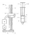
- FIG. 1is a block diagram illustrating syringe imaging system 100 in accordance with certain embodiments.
- Syringe imaging system 100includes an imaging device 101 for capturing images of a syringe 150 .
- the captured imagesare provided to a processor 105 , which evaluates the image to determine the internal diameter D i of syringe 150 and the distance L between the bung 152 on the plunger 151 and the bottom 154 of the barrel 153 of syringe 150 .
- the term “bung,” as used herein,may refer either to a gasket provided at the bottom of a plunger of a syringe, or alternatively, to the bottom surface of the plunger (e.g., where there is no gasket provided).
- imaging device 101may be mounted on a motor-driven carriage 102 , which carries imaging device 101 in a path parallel to syringe 150 along a guide rail 103 when driven by lead screw 104 .
- a motor 106 operably coupled to processor 105may be used to rotate lead screw 104 via one or more gears, such as gears 108 and 109 .
- processor 105may employ an edge detection algorithm.
- the processorevaluates the image in a predetermined horizontal orientation to locate internal surfaces (e.g., opposite sides of a circular barrel) or “walls” of barrel 153 , based upon detected sharp changes in the luminous intensity of the captured image along the horizontal orientation.
- edge detection algorithmsmay compute a derivative of this intensity change, and determine, based upon a predetermined threshold, whether the rate of change of intensity represents an internal wall of barrel 153 .
- barrel 153 of syringe 150should be transparent or at least translucent in a wavelength that imaging device 101 is capable of recording.
- syringes which are transparent to visible lightcan be easily imaged with a commercial, off-the-shelf (“COTS”) charge-coupled device (“CCD”) or a complementary metal oxide semiconductor (“CMOS”) camera module.
- COTScommercial, off-the-shelf
- CMOScomplementary metal oxide semiconductor
- Other syringes, which are transparent or translucent in other wavelengthsmay also be utilized with appropriate imaging devices (e.g., ultraviolet, infrared, etc.).
- imaging device 101may be configured to capture images of syringe 150 in any wavelength in the electromagnetic spectrum, and the scope of the present invention is not limited by the foregoing exemplary embodiments.
- syringe 150is sufficiently small, or if imaging device 101 can capture a sufficiently large field of view, a single captured image may be processed by processor 105 , in a similar manner to that described above, to determine the location of bung 152 and bottom 154 using an edge detection algorithm. For larger syringes, however, it may be preferable to move imaging device 101 (via motor-driven carriage 102 ) along the length of syringe 150 , capturing multiple images along the way.
- processor 105is provided with information about the position of motor-driven carriage 102 by linear potentiometer 110 . Accordingly, a captured image of bung 152 may be associated with a first linear position on guide rail 103 , while a captured image of bottom 154 may be associated with a second linear position on guide rail 103 , such that processor 105 can determine, based upon the distance traveled by motor-driven carriage (as determined by linear potentiometer 110 ), the distance L between bung 152 and bottom 154 .
- any one of a number of devices for sensing linear displacementmay be used to provide information about the position of imaging device 101 to processor 105 .
- a rotary encodermay be used in conjunction with one of motor 106 or gears 108 and 109 to determine a position of motor-driven carriage 102 based upon a known pitch of lead screw 103 .
- Other similar deviceswill be readily apparent to those of skill in the art, and are, for the sake of brevity, not recited herein.
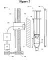
- FIG. 2illustrates a syringe imaging system 200 in accordance with certain embodiments, in which a graduated window 210 is used to determine the position of an imaging device 201 with respect to a syringe 250 .
- syringe imaging system 200includes imaging device 201 for capturing images of syringe 250 .
- the captured imagesare provided to a processor 205 , which evaluates the image to determine the internal diameter D i of syringe 150 and the distance L between the bung and the bottom of syringe 250 .
- Imaging device 201is mounted on a motor-driven carriage 202 , which carries imaging device 201 in a path parallel to syringe 250 along a guide rail 203 when driven by lead screw 204 .
- a motor 206 operably coupled to processor 205is used to rotate lead screw 204 via gears 208 and 209 .
- syringe imaging system 200includes graduated window 210 , through which imaging device 201 views syringe 250 .
- graduated window 210includes a number of graduations 211 , which are visible in the images captured by imaging device 201 .
- Graduations 211may be, for example, etchings in window 210 , or markings upon a surface of window 210 .
- Processor 205is configured to detect graduations 211 in the captured images, and to determine therefrom the vertical position of motor-driven carriage 202 and imaging device 201 . With this information, processor 205 can determine the distance L between the bung 252 and the bottom 254 of the barrel 253 of syringe 250 .
- a light source 260may be provided opposite syringe 250 from imaging device 201 .
- Light source 260may provide illumination at a wavelength in which syringe 250 is transparent or at least translucent (e.g., not opaque), and in which imaging device 201 is capable of capturing images.
- a syringeneed not be a simple cylinder for a syringe imaging system to calculate the remaining volume thereof.
- syringe 250has a barrel with a circular cross section, but a bung and a bottom with a partially conic shape.
- a 2-D imaging arraymay be utilized, without a motor-driven carriage, to capture one or more images of a syringe from which a processor can determine both the internal diameter and remaining plunger travel of a syringe.
- a combination of several 2-D and/or linear arraysmay be utilized, one oriented parallel to the barrel of the syringe to determine the remaining plunger travel thereof, and another oriented perpendicular to the barrel to determine the internal diameter thereof.
- Syringe infusion pump 300includes a housing 320 , on which is mounted a bracket 321 .
- the bracketis configured to receive a syringe 350 , and to retain syringe 350 by a flange 355 thereof.
- Syringe infusion pump 300further includes a syringe driver 322 which is configured to actuate a plunger 351 of syringe 350 in response to commands from a processor 305 .
- Syringe infusion pump 300further includes an imaging device 301 configured to capture one or more images of syringe 350 .
- the captured imagesare provided to processor 305 , which evaluates the images to determine the internal diameter and remaining plunger travel of syringe 350 .
- Imaging device 301is mounted on a motor-driven carriage 302 , which carries imaging device 301 in a path parallel to syringe 350 along a guide rail 303 when driven by lead screw 304 . This facilitates capturing multiple images of syringe 350 with imaging device 301 in various positions.
- motor-driven carriage 302travels along guide rail 303 parallel to syringe 350 , carrying imaging device 301 and allowing imaging device 301 to take several images of the length of syringe 350 . As set forth above, these images are used by processor 305 to determine the internal diameter and remaining plunger travel of syringe 350 .
- Motor 306may be used to rotate lead screw 304 via one or more gears to move motor-driven carriage 302 along guide rail 303 .
- motor 306may be directly coupled to lead screw 304 , bypassing the need for gears.
- motor 306may also be configured to actuate syringe driver 322 .
- a separate motormay be used for actuating syringe driver 322 .
- a motor-driven carriagemay be moved by any one of a number of devices, including, for example, a drive belt, a drive chain, a rack-and-pinion gear arrangement, etc.
- FIG. 4is a flowchart illustrating a method of determining the remaining volume of a syringe, according to certain embodiments.
- the methodbegins with step 401 , in which the image captured by imaging device 301 is provided to processor 305 .
- processor 305evaluates the image in a predetermined horizontal orientation to locate internal surfaces (e.g., opposite sides of a circular barrel) or “walls” of syringe 350 , using an edge detection algorithm.
- processor 305measures the distance between the walls located in step 402 .
- processor 305may be pre-programmed with information regarding the focal distance of imaging device 301 , such that the scale for the captured image is known, to assist in the determination of distance between the walls.
- processor 305evaluates the image in a predetermined vertical orientation to locate the bung and the bottom of the barrel of syringe 350 , using an edge detection algorithm.
- processor 305measures the distance between the bung and the bottom located in step 404 . Based upon the distances measured in steps 403 and 405 , processor 305 calculates the remaining volume of syringe 350 in step 406 .
- a method of determining the remaining volume of a syringehas application to any number of different syringe imaging systems, such as, for example, the syringe imaging systems illustrated in FIGS. 1 and 2 .
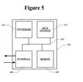
- FIG. 5is a block diagram that illustrates a computer system 500 upon which an embodiment may be implemented.
- Computer system 500includes a bus 502 or other communication mechanism for communicating information, and a processor 504 coupled with bus 502 for processing information.
- Computer system 500also includes a memory 506 , such as a random access memory (“RAM”) or other dynamic storage device, coupled to bus 502 for storing information and instructions to be executed by processor 504 .
- Memory 506may also be used for storing temporary variable or other intermediate information during execution of instructions to be executed by processor 504 .
- Computer system 500further includes a data storage device 510 , such as a magnetic disk or optical disk, coupled to bus 502 for storing information and instructions.
- Computer system 500may be coupled via I/O module 508 to a display device (not illustrated), such as a cathode ray tube (“CRT”) or liquid crystal display (“LCD”) for displaying information to a computer user.
- a display devicesuch as a cathode ray tube (“CRT”) or liquid crystal display (“LCD”) for displaying information to a computer user.
- An input devicesuch as, for example, a keyboard or a mouse may also be coupled to computer system 500 via I/O module 508 for communicating information and command selections to processor 504 .
- calculating the remaining volume of a syringeis performed by a computer system 500 in response to processor 504 executing one or more sequences of one or more instructions contained in memory 506 .
- Such instructionsmay be read into memory 506 from another machine-readable medium, such as data storage device 510 .
- Execution of the sequences of instructions contained in main memory 506causes processor 504 to perform the process steps described herein.
- processors in a multi-processing arrangementmay also be employed to execute the sequences of instructions contained in memory 506 .
- hard-wired circuitrymay be used in place of or in combination with software instructions to implement various embodiments. Thus, embodiments are not limited to any specific combination of hardware circuitry and software.
- machine-readable mediumrefers to any medium that participates in providing instructions to processor 504 for execution. Such a medium may take many forms, including, but not limited to, non-volatile media, volatile media, and transmission media.
- Non-volatile mediainclude, for example, optical or magnetic disks, such as data storage device 510 .
- Volatile mediainclude dynamic memory, such as memory 506 .
- Transmission mediainclude coaxial cables, copper wire, and fiber optics, including the wires that comprise bus 502 . Transmission media can also take the form of acoustic or light waves, such as those generated during radio frequency and infrared data communications.
- Machine-readable mediainclude, for example, floppy disk, a flexible disk, hard disk, magnetic tape, any other magnetic medium, a CD-ROM, DVD, any other optical medium, punch cards, paper tape, any other physical medium with patterns of holes, a RAM, a PROM, an EPROM, a FLASH EPROM, any other memory chip or cartridge, a carrier wave, or any other medium from which a computer can read.
Landscapes
- Health & Medical Sciences (AREA)
- Heart & Thoracic Surgery (AREA)
- Life Sciences & Earth Sciences (AREA)
- Veterinary Medicine (AREA)
- Vascular Medicine (AREA)
- Engineering & Computer Science (AREA)
- Anesthesiology (AREA)
- Public Health (AREA)
- Biomedical Technology (AREA)
- Hematology (AREA)
- General Health & Medical Sciences (AREA)
- Animal Behavior & Ethology (AREA)
- Physics & Mathematics (AREA)
- General Physics & Mathematics (AREA)
- Fluid Mechanics (AREA)
- Infusion, Injection, And Reservoir Apparatuses (AREA)
- Endoscopes (AREA)
Abstract
Description
Claims (24)
Priority Applications (12)
| Application Number | Priority Date | Filing Date | Title |
|---|---|---|---|
| US12/021,786US8161810B2 (en) | 2008-01-29 | 2008-01-29 | Syringe imaging systems |
| JP2010545166AJP2011510749A (en) | 2008-01-29 | 2009-01-29 | Syringe imaging system |
| PCT/US2009/032453WO2009097441A1 (en) | 2008-01-29 | 2009-01-29 | Syringe imaging systems |
| ES09706470TES2386417T3 (en) | 2008-01-29 | 2009-01-29 | Imaging systems of a syringe |
| BRPI0906431-1ABRPI0906431A2 (en) | 2008-01-29 | 2009-01-29 | Syringe Imaging Systems |
| AU2009209094AAU2009209094A1 (en) | 2008-01-29 | 2009-01-29 | Syringe imaging systems |
| RU2010136289/14ARU2010136289A (en) | 2008-01-29 | 2009-01-29 | SYRINGE IMAGE SYSTEM |
| CN2009801113606ACN101980732A (en) | 2008-01-29 | 2009-01-29 | Syringe imaging systems |
| CA2714294ACA2714294A1 (en) | 2008-01-29 | 2009-01-29 | Syringe imaging systems |
| EP09706470AEP2247324B1 (en) | 2008-01-29 | 2009-01-29 | Syringe imaging systems |
| AT09706470TATE554812T1 (en) | 2008-01-29 | 2009-01-29 | SYRINGE IMAGING SYSTEMS |
| ZA2010/06072AZA201006072B (en) | 2008-01-29 | 2010-08-25 | Syringe imaging systems |
Applications Claiming Priority (1)
| Application Number | Priority Date | Filing Date | Title |
|---|---|---|---|
| US12/021,786US8161810B2 (en) | 2008-01-29 | 2008-01-29 | Syringe imaging systems |
Publications (2)
| Publication Number | Publication Date |
|---|---|
| US20090188311A1 US20090188311A1 (en) | 2009-07-30 |
| US8161810B2true US8161810B2 (en) | 2012-04-24 |
Family
ID=40527940
Family Applications (1)
| Application Number | Title | Priority Date | Filing Date |
|---|---|---|---|
| US12/021,786Active2031-02-24US8161810B2 (en) | 2008-01-29 | 2008-01-29 | Syringe imaging systems |
Country Status (12)
| Country | Link |
|---|---|
| US (1) | US8161810B2 (en) |
| EP (1) | EP2247324B1 (en) |
| JP (1) | JP2011510749A (en) |
| CN (1) | CN101980732A (en) |
| AT (1) | ATE554812T1 (en) |
| AU (1) | AU2009209094A1 (en) |
| BR (1) | BRPI0906431A2 (en) |
| CA (1) | CA2714294A1 (en) |
| ES (1) | ES2386417T3 (en) |
| RU (1) | RU2010136289A (en) |
| WO (1) | WO2009097441A1 (en) |
| ZA (1) | ZA201006072B (en) |
Cited By (20)
| Publication number | Priority date | Publication date | Assignee | Title |
|---|---|---|---|---|
| US20130057677A1 (en)* | 2010-04-26 | 2013-03-07 | Becton Dickinson France | Device, kit and method for inspection of an article |
| US20150253289A1 (en)* | 2012-10-12 | 2015-09-10 | Abbvie Inc. | Characterization and/or detection of structural characteristics associated with syringes and/or automatic injection devices based on acoustics |
| US9295778B2 (en) | 2011-12-21 | 2016-03-29 | Deka Products Limited Partnership | Syringe pump |
| US9514518B2 (en) | 2002-06-14 | 2016-12-06 | Baxter International Inc. | Infusion pump including syringe plunger position sensor |
| US9744300B2 (en) | 2011-12-21 | 2017-08-29 | Deka Products Limited Partnership | Syringe pump and related method |
| US9789247B2 (en) | 2011-12-21 | 2017-10-17 | Deka Products Limited Partnership | Syringe pump, and related method and system |
| US9976551B2 (en) | 2012-12-07 | 2018-05-22 | Smiths Medical Asd, Inc. | Syringe characterization |
| US10391241B2 (en) | 2010-01-22 | 2019-08-27 | Deka Products Limited Partnership | Syringe pump having a pressure sensor assembly |
| US10722645B2 (en) | 2011-12-21 | 2020-07-28 | Deka Products Limited Partnership | Syringe pump, and related method and system |
| EP3727525A1 (en)* | 2017-12-18 | 2020-10-28 | Patients Pending Ltd. | Liquid delivery cap devices, systems, and methods |
| US11183284B2 (en) | 2015-06-01 | 2021-11-23 | Digital Hospital, Inc. | Dosage confirmation apparatus |
| US11217340B2 (en) | 2011-12-21 | 2022-01-04 | Deka Products Limited Partnership | Syringe pump having a pressure sensor assembly |
| US11358148B2 (en) | 2018-03-30 | 2022-06-14 | Idexx Laboratories, Inc. | Point-of-care diagnostic systems and containers for same |
| US11441997B2 (en) | 2018-03-30 | 2022-09-13 | Idexx Laboratories, Inc. | Quality control for point-of-care diagnostic systems |
| US11541396B2 (en) | 2018-03-30 | 2023-01-03 | Idexx Laboratories, Inc. | Point-of-care diagnostic systems and containers for same |
| US11801342B2 (en) | 2017-07-19 | 2023-10-31 | Smiths Medical Asd, Inc. | Housing arrangements for infusion pumps |
| US12048830B2 (en) | 2019-03-07 | 2024-07-30 | Kpr U.S., Llc | Delivery of fluid from a syringe |
| US12098738B2 (en) | 2011-12-21 | 2024-09-24 | Deka Products Limited Partnership | System, method, and apparatus for clamping |
| US12131826B2 (en) | 2011-12-21 | 2024-10-29 | Deka Products Limited Partnership | Syringe pump and related method |
| US12214158B2 (en) | 2018-05-03 | 2025-02-04 | Smiths Medical Asd, Inc. | Systems and methods for syringe handling |
Families Citing this family (42)
| Publication number | Priority date | Publication date | Assignee | Title |
|---|---|---|---|---|
| USD1031029S1 (en) | 2003-11-25 | 2024-06-11 | Bayer Healthcare Llc | Syringe plunger |
| US8381581B2 (en)* | 2009-09-23 | 2013-02-26 | Brooks Automation, Inc. | Volumetric measurement |
| EP2327431A1 (en)* | 2009-11-25 | 2011-06-01 | Letcat Aktiebolag | Medical delivery device |
| EP2526986B1 (en)* | 2010-03-01 | 2016-11-30 | Panasonic Healthcare Holdings Co., Ltd. | Medicine administering device |
| TWI633902B (en)* | 2010-03-22 | 2018-09-01 | 賽諾菲阿凡提斯德意志有限公司 | Device, method, system and computer program for determining information related to a medical device |
| PL2696848T3 (en) | 2011-04-15 | 2020-12-28 | Janssen Pharmaceutica N.V. | Freeze dried drug nanosuspensions |
| CN103293157B (en)* | 2012-03-02 | 2015-12-16 | 厚美德生物科技股份有限公司 | Optical measuring device, optical measuring system and optical measuring method |
| JP5875469B2 (en)* | 2012-06-05 | 2016-03-02 | 株式会社トーショー | Syringe weighing system |
| JP6108270B2 (en)* | 2012-06-26 | 2017-04-05 | パナソニックIpマネジメント株式会社 | Chemical inspection device |
| DK2945668T3 (en) | 2013-01-15 | 2018-09-03 | Sanofi Aventis Deutschland | ASSEMBLY ASSEMBLY FOR A MEDICAL INJECTION DEVICE FOR GENERATION OF USE REPORTS ON THE USE OF THE DIGITAL IMAGE INJECTION DEVICE |
| WO2015066342A1 (en)* | 2013-11-04 | 2015-05-07 | Siemens Healthcare Diagnostics Inc. | Methods and apparatus for determining aspiration and/or dispensing volume and/or pipette positioning |
| AU2015231396B2 (en) | 2014-03-19 | 2018-12-06 | Bayer Healthcare Llc | System for syringe engagement to an injector |
| EP3197535B1 (en)* | 2014-09-23 | 2018-11-14 | Romaltek Medical, S.L. | Monitoring manually operated syringes |
| WO2016062605A1 (en) | 2014-10-21 | 2016-04-28 | Sanofi-Aventis Deutschland Gmbh | Recording dose data from drug injection devices using optical character recognition (ocr) |
| DK3341048T3 (en) | 2015-08-28 | 2023-08-21 | Bayer Healthcare Llc | SYSTEM AND METHOD FOR VERIFYING INJECTION FLUID FILLING AND IMAGE RECOGNITION OF POWER INJECTOR SYSTEM TRAITS |
| WO2017209899A1 (en)* | 2016-06-03 | 2017-12-07 | Amgen Inc. | Impact testing apparatuses and methods for drug delivery devices |
| US10532166B2 (en) | 2016-07-08 | 2020-01-14 | Bayer Heatlhcare Llc | System and method for identifying a fill volume of a fluid chamber |
| KR101725457B1 (en)* | 2016-11-03 | 2017-04-11 | (주)스마트코리아 | individual control multi-axis syringe pump having monitoring function |
| ES3010641T3 (en)* | 2017-08-09 | 2025-04-04 | Amgen Inc | Image processing techniques for plunger depth measurement |
| US10991264B2 (en)* | 2017-11-23 | 2021-04-27 | Omnicell, Inc. | Multi-camera imaging for IV compounding |
| US10596319B2 (en) | 2017-11-23 | 2020-03-24 | Aesynt Incorporated | Compounding device system |
| US11335444B2 (en) | 2017-11-30 | 2022-05-17 | Omnicell, Inc. | IV compounding systems and methods |
| FI127724B (en)* | 2017-12-22 | 2019-01-15 | Salecron Oy | Device and method for measuring and recording a dose of medicine in a medicine dosing device |
| US10869800B2 (en) | 2018-03-26 | 2020-12-22 | Augustine Biomedical + Design, LLC | Relocation module and methods for surgical equipment |
| US10507153B2 (en) | 2018-03-26 | 2019-12-17 | Augustine Biomedical + Design, LLC | Relocation modules and methods for surgical field |
| US11426318B2 (en) | 2020-05-20 | 2022-08-30 | Augustine Biomedical + Design, LLC | Medical module including automated dose-response record system |
| US11160710B1 (en) | 2020-05-20 | 2021-11-02 | Augustine Biomedical + Design, LLC | Relocation module and methods for surgical equipment |
| US11219570B2 (en) | 2018-03-26 | 2022-01-11 | Augustine Biomedical + Design, LLC | Relocation module and methods for surgical equipment |
| US11446196B2 (en) | 2018-03-26 | 2022-09-20 | Augustine Biomedical + Design, LLC | Relocation module and methods for surgical equipment |
| US11291602B2 (en) | 2018-03-26 | 2022-04-05 | Augustine Biomedical + Design, LLC | Relocation module and methods for surgical equipment |
| US11432982B2 (en) | 2018-03-26 | 2022-09-06 | Augustine Biomedical + Design, LLC | Relocation module and methods for surgical equipment |
| TWI678219B (en)* | 2018-04-10 | 2019-12-01 | 程揚生技有限公司 | Soft tissue automatic injection device |
| FR3092494B1 (en)* | 2019-02-08 | 2021-09-24 | Ceclean | System for cleaning and / or disinfecting a hollow tube, in particular a door handle crutch |
| JP6777334B2 (en)* | 2019-05-29 | 2020-10-28 | ロマルテック メディカル,エス.エル. | Monitoring of manually operated syringes |
| KR102421966B1 (en)* | 2019-12-27 | 2022-07-19 | 지피헬스 주식회사 | Portable auto injection apparatus with short length |
| EP4153267A4 (en)* | 2020-05-20 | 2023-10-18 | Augustine Biomedical + Design, LLC | IV MEDICATION AND FLUID DELIVERY SYSTEMS |
| BR112022023788A2 (en) | 2020-06-18 | 2022-12-27 | Bayer Healthcare Llc | SYSTEM AND METHOD OF COUPLING A SYRINGE PLUNGER WITH AN INJECTOR |
| MX2023011513A (en)* | 2021-04-22 | 2023-10-05 | Amgen Inc | Methods and systems for automated syringe quality evaluation. |
| US20250242111A1 (en)* | 2021-09-09 | 2025-07-31 | Brighter Sight Inc. | Method for providing information on dosage of medication for administration using a syringe |
| WO2023055780A1 (en)* | 2021-09-29 | 2023-04-06 | Amgen Inc. | Apparatuses, systems and methods for plunger-stopper depth measurement in pre-filled syringes |
| EP4184517A1 (en)* | 2021-11-17 | 2023-05-24 | Augustine Biomedical and Design, LLC | Relocation module and methods for surgical equipment |
| GB202211146D0 (en)* | 2022-07-29 | 2022-09-14 | Augmenticon Gmbh | Automated syringe fill state measurement |
Citations (19)
| Publication number | Priority date | Publication date | Assignee | Title |
|---|---|---|---|---|
| US4838857A (en) | 1985-05-29 | 1989-06-13 | Becton, Dickinson And Company | Medical infusion device |
| US5237309A (en) | 1987-07-20 | 1993-08-17 | Frantz Medical Development, Ltd. | Pump cassette and method of pumping |
| US5425716A (en) | 1991-08-09 | 1995-06-20 | Atom Kabushiki Kaisha | Infusion apparatus |
| WO1996025963A1 (en) | 1995-02-24 | 1996-08-29 | Harvard Clinical Technology, Inc. | Infusion pump for at least one syringe |
| US5615007A (en) | 1994-05-20 | 1997-03-25 | Eisai Co., Ltd. | Method of detecting crack and chip in flange of syringe |
| US5651775A (en)* | 1995-07-12 | 1997-07-29 | Walker; Richard Bradley | Medication delivery and monitoring system and methods |
| US5747350A (en)* | 1993-04-02 | 1998-05-05 | Boehringer Mannheim Gmbh | System for dosing liquids |
| US5928197A (en) | 1993-11-24 | 1999-07-27 | Liebel-Flarsheim Company | Controlling plunger drives for fluid injections in animals |
| EP1049258A2 (en) | 1999-04-28 | 2000-11-02 | Smiths Industries Public Limited Company | Syringe pump |
| EP1279410A1 (en) | 1994-10-06 | 2003-01-29 | Baxter International Inc. | A syringe infusion pump having a syringe plunger sensor |
| US20030233069A1 (en) | 2002-06-14 | 2003-12-18 | John Gillespie | Infusion pump |
| US20040024361A1 (en)* | 2002-08-02 | 2004-02-05 | Mallinckrodt Inc. | Injector |
| EP1433456A1 (en) | 2001-09-12 | 2004-06-30 | Terumo Kabushiki Kaisha | Medicine container and medicine injector comprising the same |
| WO2005004952A1 (en) | 2003-07-09 | 2005-01-20 | Smiths Group Plc | Syringe pump with plunger head detector |
| US20050217476A1 (en) | 2004-04-06 | 2005-10-06 | Liang Dong C | Robotic syringe system utilizing a liquid piston for the measurement and dispensing of fluid samples |
| US20060129104A1 (en)* | 2001-01-18 | 2006-06-15 | Cowan Kevin P | Encoding and sensing of syringe information |
| US20060144942A1 (en) | 2000-03-22 | 2006-07-06 | Docusys, Inc. | Drug delivery and monitoring system |
| US20060178578A1 (en) | 2005-02-10 | 2006-08-10 | Dennis Tribble | Vision system to calculate a fluid volume in a container |
| US7169135B2 (en)* | 2000-04-04 | 2007-01-30 | Acist Medical Systems, Inc. | Fluid management and component detection system |
Family Cites Families (6)
| Publication number | Priority date | Publication date | Assignee | Title |
|---|---|---|---|---|
| JP3203570B2 (en)* | 1992-11-27 | 2001-08-27 | 日本光電工業株式会社 | Syringe pump |
| JP3381301B2 (en)* | 1993-04-14 | 2003-02-24 | 株式会社ジェイ・エム・エス | Syringe pump |
| JP2000070365A (en)* | 1998-08-27 | 2000-03-07 | Japan Servo Co Ltd | Infusion device |
| JP2006132984A (en)* | 2004-11-02 | 2006-05-25 | Sumitomo Heavy Ind Ltd | Method and apparatus for dispensing radioactive liquid |
| JP2007132774A (en)* | 2005-11-10 | 2007-05-31 | Nippon Electric Glass Co Ltd | Apparatus for measuring glass tube diameter |
| JP2007167791A (en)* | 2005-12-22 | 2007-07-05 | Shibaura Mechatronics Corp | Paste coating apparatus, display panel manufacturing apparatus using the same, and paste coating method |
- 2008
- 2008-01-29USUS12/021,786patent/US8161810B2/enactiveActive
- 2009
- 2009-01-29WOPCT/US2009/032453patent/WO2009097441A1/enactiveApplication Filing
- 2009-01-29RURU2010136289/14Apatent/RU2010136289A/ennot_activeApplication Discontinuation
- 2009-01-29BRBRPI0906431-1Apatent/BRPI0906431A2/ennot_activeIP Right Cessation
- 2009-01-29AUAU2009209094Apatent/AU2009209094A1/ennot_activeAbandoned
- 2009-01-29ESES09706470Tpatent/ES2386417T3/enactiveActive
- 2009-01-29CNCN2009801113606Apatent/CN101980732A/enactivePending
- 2009-01-29EPEP09706470Apatent/EP2247324B1/enactiveActive
- 2009-01-29JPJP2010545166Apatent/JP2011510749A/enactivePending
- 2009-01-29CACA2714294Apatent/CA2714294A1/ennot_activeAbandoned
- 2009-01-29ATAT09706470Tpatent/ATE554812T1/enactive
- 2010
- 2010-08-25ZAZA2010/06072Apatent/ZA201006072B/enunknown
Patent Citations (22)
| Publication number | Priority date | Publication date | Assignee | Title |
|---|---|---|---|---|
| US4838857A (en) | 1985-05-29 | 1989-06-13 | Becton, Dickinson And Company | Medical infusion device |
| US5237309A (en) | 1987-07-20 | 1993-08-17 | Frantz Medical Development, Ltd. | Pump cassette and method of pumping |
| US5425716A (en) | 1991-08-09 | 1995-06-20 | Atom Kabushiki Kaisha | Infusion apparatus |
| US5747350A (en)* | 1993-04-02 | 1998-05-05 | Boehringer Mannheim Gmbh | System for dosing liquids |
| US5928197A (en) | 1993-11-24 | 1999-07-27 | Liebel-Flarsheim Company | Controlling plunger drives for fluid injections in animals |
| US5615007A (en) | 1994-05-20 | 1997-03-25 | Eisai Co., Ltd. | Method of detecting crack and chip in flange of syringe |
| EP1279410A1 (en) | 1994-10-06 | 2003-01-29 | Baxter International Inc. | A syringe infusion pump having a syringe plunger sensor |
| WO1996025963A1 (en) | 1995-02-24 | 1996-08-29 | Harvard Clinical Technology, Inc. | Infusion pump for at least one syringe |
| US5651775A (en)* | 1995-07-12 | 1997-07-29 | Walker; Richard Bradley | Medication delivery and monitoring system and methods |
| USRE38189E1 (en) | 1995-07-12 | 2003-07-15 | Docusys, Inc. | Medication delivery and monitoring system and methods |
| EP1049258A2 (en) | 1999-04-28 | 2000-11-02 | Smiths Industries Public Limited Company | Syringe pump |
| US6500151B1 (en) | 1999-04-28 | 2002-12-31 | Smiths Group Plc | Syringe pump |
| US20060144942A1 (en) | 2000-03-22 | 2006-07-06 | Docusys, Inc. | Drug delivery and monitoring system |
| US7169135B2 (en)* | 2000-04-04 | 2007-01-30 | Acist Medical Systems, Inc. | Fluid management and component detection system |
| US20060129104A1 (en)* | 2001-01-18 | 2006-06-15 | Cowan Kevin P | Encoding and sensing of syringe information |
| EP1433456A1 (en) | 2001-09-12 | 2004-06-30 | Terumo Kabushiki Kaisha | Medicine container and medicine injector comprising the same |
| US20030233069A1 (en) | 2002-06-14 | 2003-12-18 | John Gillespie | Infusion pump |
| US20040024361A1 (en)* | 2002-08-02 | 2004-02-05 | Mallinckrodt Inc. | Injector |
| WO2005004952A1 (en) | 2003-07-09 | 2005-01-20 | Smiths Group Plc | Syringe pump with plunger head detector |
| US20060167414A1 (en) | 2003-07-09 | 2006-07-27 | Scott Adrian P | Syringe pump with barrel size sensor arm |
| US20050217476A1 (en) | 2004-04-06 | 2005-10-06 | Liang Dong C | Robotic syringe system utilizing a liquid piston for the measurement and dispensing of fluid samples |
| US20060178578A1 (en) | 2005-02-10 | 2006-08-10 | Dennis Tribble | Vision system to calculate a fluid volume in a container |
Non-Patent Citations (1)
| Title |
|---|
| PCT International Search Report/Written Opinion for International Application No. PCT/US2009/032453, mailed May 4, 2009. |
Cited By (35)
| Publication number | Priority date | Publication date | Assignee | Title |
|---|---|---|---|---|
| US10092690B2 (en) | 2002-06-14 | 2018-10-09 | Baxter International Inc. | Infusion pump including syringe sensing |
| US9514518B2 (en) | 2002-06-14 | 2016-12-06 | Baxter International Inc. | Infusion pump including syringe plunger position sensor |
| US10391241B2 (en) | 2010-01-22 | 2019-08-27 | Deka Products Limited Partnership | Syringe pump having a pressure sensor assembly |
| US20130057677A1 (en)* | 2010-04-26 | 2013-03-07 | Becton Dickinson France | Device, kit and method for inspection of an article |
| US9176071B2 (en)* | 2010-04-26 | 2015-11-03 | Becton Dickinson France | Device, kit and method for inspection of an article |
| US10245374B2 (en) | 2011-12-21 | 2019-04-02 | Deka Products Limited Partnership | Syringe pump |
| US12431231B2 (en) | 2011-12-21 | 2025-09-30 | DEKA Products Limited Parternship | Syringe pump |
| US9789247B2 (en) | 2011-12-21 | 2017-10-17 | Deka Products Limited Partnership | Syringe pump, and related method and system |
| US9744300B2 (en) | 2011-12-21 | 2017-08-29 | Deka Products Limited Partnership | Syringe pump and related method |
| US9295778B2 (en) | 2011-12-21 | 2016-03-29 | Deka Products Limited Partnership | Syringe pump |
| US11664106B2 (en) | 2011-12-21 | 2023-05-30 | Deka Products Limited Partnership | Syringe pump |
| US11615886B2 (en) | 2011-12-21 | 2023-03-28 | Deka Products Limited Partnership | Syringe pump and related method |
| US10561787B2 (en) | 2011-12-21 | 2020-02-18 | Deka Products Limited Partnership | Syringe pump and related method |
| US10722645B2 (en) | 2011-12-21 | 2020-07-28 | Deka Products Limited Partnership | Syringe pump, and related method and system |
| US11826543B2 (en) | 2011-12-21 | 2023-11-28 | Deka Products Limited Partneship | Syringe pump, and related method and system |
| US11129933B2 (en) | 2011-12-21 | 2021-09-28 | Deka Products Limited Partnership | Syringe pump, and related method and system |
| US12131826B2 (en) | 2011-12-21 | 2024-10-29 | Deka Products Limited Partnership | Syringe pump and related method |
| US11217340B2 (en) | 2011-12-21 | 2022-01-04 | Deka Products Limited Partnership | Syringe pump having a pressure sensor assembly |
| US12098738B2 (en) | 2011-12-21 | 2024-09-24 | Deka Products Limited Partnership | System, method, and apparatus for clamping |
| US12080400B2 (en) | 2011-12-21 | 2024-09-03 | Deka Products Limited Partnership | Syringe pump having a pressure sensor assembly |
| US9753015B2 (en)* | 2012-10-12 | 2017-09-05 | Abbvie Inc. | Characterization and/or detection of structural characteristics associated with syringes and/or automatic injection devices based on acoustics |
| US20150253289A1 (en)* | 2012-10-12 | 2015-09-10 | Abbvie Inc. | Characterization and/or detection of structural characteristics associated with syringes and/or automatic injection devices based on acoustics |
| US9976551B2 (en) | 2012-12-07 | 2018-05-22 | Smiths Medical Asd, Inc. | Syringe characterization |
| US11183284B2 (en) | 2015-06-01 | 2021-11-23 | Digital Hospital, Inc. | Dosage confirmation apparatus |
| US11801342B2 (en) | 2017-07-19 | 2023-10-31 | Smiths Medical Asd, Inc. | Housing arrangements for infusion pumps |
| EP4559494A3 (en)* | 2017-12-18 | 2025-08-06 | Patients Pending Ltd. | Liquid delivery cap devices, systems, and methods |
| EP3727525A1 (en)* | 2017-12-18 | 2020-10-28 | Patients Pending Ltd. | Liquid delivery cap devices, systems, and methods |
| US11541396B2 (en) | 2018-03-30 | 2023-01-03 | Idexx Laboratories, Inc. | Point-of-care diagnostic systems and containers for same |
| US11887727B2 (en) | 2018-03-30 | 2024-01-30 | Idexx Laboratories, Inc. | Quality control for point-of-care diagnostic systems |
| US11441997B2 (en) | 2018-03-30 | 2022-09-13 | Idexx Laboratories, Inc. | Quality control for point-of-care diagnostic systems |
| US11358148B2 (en) | 2018-03-30 | 2022-06-14 | Idexx Laboratories, Inc. | Point-of-care diagnostic systems and containers for same |
| US12303902B2 (en) | 2018-03-30 | 2025-05-20 | Idexx Laboratories Inc. | Point-of-care diagnostic systems and containers for same |
| US12374448B2 (en) | 2018-03-30 | 2025-07-29 | Idexx Laboratories, Inc. | Quality control for point-of-care diagnostic systems |
| US12214158B2 (en) | 2018-05-03 | 2025-02-04 | Smiths Medical Asd, Inc. | Systems and methods for syringe handling |
| US12048830B2 (en) | 2019-03-07 | 2024-07-30 | Kpr U.S., Llc | Delivery of fluid from a syringe |
Also Published As
| Publication number | Publication date |
|---|---|
| CN101980732A (en) | 2011-02-23 |
| EP2247324B1 (en) | 2012-04-25 |
| AU2009209094A1 (en) | 2009-08-06 |
| ZA201006072B (en) | 2013-01-30 |
| BRPI0906431A2 (en) | 2015-07-14 |
| ATE554812T1 (en) | 2012-05-15 |
| CA2714294A1 (en) | 2009-08-06 |
| EP2247324A1 (en) | 2010-11-10 |
| US20090188311A1 (en) | 2009-07-30 |
| ES2386417T3 (en) | 2012-08-20 |
| WO2009097441A1 (en) | 2009-08-06 |
| JP2011510749A (en) | 2011-04-07 |
| RU2010136289A (en) | 2012-03-10 |
Similar Documents
| Publication | Publication Date | Title |
|---|---|---|
| US8161810B2 (en) | Syringe imaging systems | |
| US20220296806A1 (en) | Infusion system and method which utilizes dual wavelength optical air-in-line detection | |
| JP4658599B2 (en) | Optical deflection sensor for injection devices. | |
| US9134735B2 (en) | Intravenous flow rate controller | |
| US11392781B2 (en) | Systems and methods for inductive identification | |
| US20140142537A1 (en) | Injection System with Capacitive Sensing | |
| EP3219345A1 (en) | Apparatus and method for recording the amount of medicament ejected from an injection device | |
| EP2680903A1 (en) | Smart medication waste disposal | |
| EP3197535A1 (en) | Monitoring manually operated syringes | |
| US20170213012A1 (en) | Systems and methods for capacitive identification | |
| US11833333B2 (en) | Drug tracking device | |
| US20200080929A1 (en) | Matter tracking system | |
| CN218652701U (en) | Detection device for measuring catheter/guide wire movement | |
| US20230004256A1 (en) | Detection device and infusion pump | |
| CN102905738B (en) | Ophthalmic surgical cassettes with identification features | |
| CN117338427B (en) | A photodynamic interventional catheter end positioning system and method | |
| CN119524256A (en) | Pipe blockage detection method and pipe blockage detection device | |
| WO2024137557A1 (en) | Manual bolus volume estimation | |
| CN119147172A (en) | Liquid level detection method, system, device, storage medium and electronic equipment |
Legal Events
| Date | Code | Title | Description |
|---|---|---|---|
| AS | Assignment | Owner name:CARDINAL HEALTH 303, INC., CALIFORNIA Free format text:ASSIGNMENT OF ASSIGNORS INTEREST;ASSIGNORS:CADIEUX, IAN;MORRIS, MATT;REEL/FRAME:020801/0039 Effective date:20080320 | |
| AS | Assignment | Owner name:CAREFUSION 303, INC.,CALIFORNIA Free format text:CHANGE OF NAME;ASSIGNOR:CARDINAL HEALTH 303, INC.;REEL/FRAME:023730/0406 Effective date:20090729 Owner name:CAREFUSION 303, INC., CALIFORNIA Free format text:CHANGE OF NAME;ASSIGNOR:CARDINAL HEALTH 303, INC.;REEL/FRAME:023730/0406 Effective date:20090729 | |
| AS | Assignment | Owner name:CAREFUSION 303, INC.,CALIFORNIA Free format text:CHANGE OF NAME;ASSIGNOR:CARDINAL HEALTH 303, INC.;REEL/FRAME:023800/0598 Effective date:20090801 Owner name:CAREFUSION 303, INC., CALIFORNIA Free format text:CHANGE OF NAME;ASSIGNOR:CARDINAL HEALTH 303, INC.;REEL/FRAME:023800/0598 Effective date:20090801 | |
| STCF | Information on status: patent grant | Free format text:PATENTED CASE | |
| FPAY | Fee payment | Year of fee payment:4 | |
| MAFP | Maintenance fee payment | Free format text:PAYMENT OF MAINTENANCE FEE, 8TH YEAR, LARGE ENTITY (ORIGINAL EVENT CODE: M1552); ENTITY STATUS OF PATENT OWNER: LARGE ENTITY Year of fee payment:8 | |
| MAFP | Maintenance fee payment | Free format text:PAYMENT OF MAINTENANCE FEE, 12TH YEAR, LARGE ENTITY (ORIGINAL EVENT CODE: M1553); ENTITY STATUS OF PATENT OWNER: LARGE ENTITY Year of fee payment:12 |