US8161780B1 - Thumb operated door lock assembly - Google Patents
Thumb operated door lock assemblyDownload PDFInfo
- Publication number
- US8161780B1 US8161780B1US12/657,375US65737510AUS8161780B1US 8161780 B1US8161780 B1US 8161780B1US 65737510 AUS65737510 AUS 65737510AUS 8161780 B1US8161780 B1US 8161780B1
- Authority
- US
- United States
- Prior art keywords
- lever
- connector
- interior
- plate
- door
- Prior art date
- Legal status (The legal status is an assumption and is not a legal conclusion. Google has not performed a legal analysis and makes no representation as to the accuracy of the status listed.)
- Active
Links
Images


Classifications
- E—FIXED CONSTRUCTIONS
- E05—LOCKS; KEYS; WINDOW OR DOOR FITTINGS; SAFES
- E05B—LOCKS; ACCESSORIES THEREFOR; HANDCUFFS
- E05B59/00—Locks with latches separate from the lock-bolts or with a plurality of latches or lock-bolts
- E—FIXED CONSTRUCTIONS
- E05—LOCKS; KEYS; WINDOW OR DOOR FITTINGS; SAFES
- E05B—LOCKS; ACCESSORIES THEREFOR; HANDCUFFS
- E05B15/00—Other details of locks; Parts for engagement by bolts of fastening devices
- E05B15/02—Striking-plates; Keepers; Bolt staples; Escutcheons
- E—FIXED CONSTRUCTIONS
- E05—LOCKS; KEYS; WINDOW OR DOOR FITTINGS; SAFES
- E05B—LOCKS; ACCESSORIES THEREFOR; HANDCUFFS
- E05B63/00—Locks or fastenings with special structural characteristics
- E05B63/16—Locks or fastenings with special structural characteristics with the handles on opposite sides moving independently
- E—FIXED CONSTRUCTIONS
- E05—LOCKS; KEYS; WINDOW OR DOOR FITTINGS; SAFES
- E05B—LOCKS; ACCESSORIES THEREFOR; HANDCUFFS
- E05B65/00—Locks or fastenings for special use
- E05B65/10—Locks or fastenings for special use for panic or emergency doors
- E05B65/1086—Locks with panic function, e.g. allowing opening from the inside without a ley even when locked from the outside
- E—FIXED CONSTRUCTIONS
- E05—LOCKS; KEYS; WINDOW OR DOOR FITTINGS; SAFES
- E05C—BOLTS OR FASTENING DEVICES FOR WINGS, SPECIALLY FOR DOORS OR WINDOWS
- E05C9/00—Arrangements of simultaneously actuated bolts or other securing devices at well-separated positions on the same wing
- E05C9/004—Faceplates ; Fixing the faceplates to the wing
- E—FIXED CONSTRUCTIONS
- E05—LOCKS; KEYS; WINDOW OR DOOR FITTINGS; SAFES
- E05C—BOLTS OR FASTENING DEVICES FOR WINGS, SPECIALLY FOR DOORS OR WINDOWS
- E05C9/00—Arrangements of simultaneously actuated bolts or other securing devices at well-separated positions on the same wing
- E05C9/02—Arrangements of simultaneously actuated bolts or other securing devices at well-separated positions on the same wing with one sliding bar for fastening when moved in one direction and unfastening when moved in opposite direction; with two sliding bars moved in the same direction when fastening or unfastening
- E05C9/026—Arrangements of simultaneously actuated bolts or other securing devices at well-separated positions on the same wing with one sliding bar for fastening when moved in one direction and unfastening when moved in opposite direction; with two sliding bars moved in the same direction when fastening or unfastening comprising key-operated locks, e.g. a lock cylinder to drive auxiliary deadbolts or latch bolts
- E—FIXED CONSTRUCTIONS
- E05—LOCKS; KEYS; WINDOW OR DOOR FITTINGS; SAFES
- E05B—LOCKS; ACCESSORIES THEREFOR; HANDCUFFS
- E05B1/00—Knobs or handles for wings; Knobs, handles, or press buttons for locks or latches on wings
- E05B1/0015—Knobs or handles which do not operate the bolt or lock, e.g. non-movable; Mounting thereof
- E—FIXED CONSTRUCTIONS
- E05—LOCKS; KEYS; WINDOW OR DOOR FITTINGS; SAFES
- E05B—LOCKS; ACCESSORIES THEREFOR; HANDCUFFS
- E05B15/00—Other details of locks; Parts for engagement by bolts of fastening devices
- E05B15/0033—Spindles for handles, e.g. square spindles
- Y—GENERAL TAGGING OF NEW TECHNOLOGICAL DEVELOPMENTS; GENERAL TAGGING OF CROSS-SECTIONAL TECHNOLOGIES SPANNING OVER SEVERAL SECTIONS OF THE IPC; TECHNICAL SUBJECTS COVERED BY FORMER USPC CROSS-REFERENCE ART COLLECTIONS [XRACs] AND DIGESTS
- Y10—TECHNICAL SUBJECTS COVERED BY FORMER USPC
- Y10S—TECHNICAL SUBJECTS COVERED BY FORMER USPC CROSS-REFERENCE ART COLLECTIONS [XRACs] AND DIGESTS
- Y10S70/00—Locks
- Y10S70/42—Lost motion devices
- Y—GENERAL TAGGING OF NEW TECHNOLOGICAL DEVELOPMENTS; GENERAL TAGGING OF CROSS-SECTIONAL TECHNOLOGIES SPANNING OVER SEVERAL SECTIONS OF THE IPC; TECHNICAL SUBJECTS COVERED BY FORMER USPC CROSS-REFERENCE ART COLLECTIONS [XRACs] AND DIGESTS
- Y10—TECHNICAL SUBJECTS COVERED BY FORMER USPC
- Y10T—TECHNICAL SUBJECTS COVERED BY FORMER US CLASSIFICATION
- Y10T292/00—Closure fasteners
- Y10T292/08—Bolts
- Y10T292/0801—Multiple
- Y10T292/0834—Sliding
- Y10T292/0836—Operating means
- Y10T292/0837—Cam and lever
- Y—GENERAL TAGGING OF NEW TECHNOLOGICAL DEVELOPMENTS; GENERAL TAGGING OF CROSS-SECTIONAL TECHNOLOGIES SPANNING OVER SEVERAL SECTIONS OF THE IPC; TECHNICAL SUBJECTS COVERED BY FORMER USPC CROSS-REFERENCE ART COLLECTIONS [XRACs] AND DIGESTS
- Y10—TECHNICAL SUBJECTS COVERED BY FORMER USPC
- Y10T—TECHNICAL SUBJECTS COVERED BY FORMER US CLASSIFICATION
- Y10T292/00—Closure fasteners
- Y10T292/08—Bolts
- Y10T292/0801—Multiple
- Y10T292/0834—Sliding
- Y10T292/0836—Operating means
- Y10T292/0843—Gear
- Y—GENERAL TAGGING OF NEW TECHNOLOGICAL DEVELOPMENTS; GENERAL TAGGING OF CROSS-SECTIONAL TECHNOLOGIES SPANNING OVER SEVERAL SECTIONS OF THE IPC; TECHNICAL SUBJECTS COVERED BY FORMER USPC CROSS-REFERENCE ART COLLECTIONS [XRACs] AND DIGESTS
- Y10—TECHNICAL SUBJECTS COVERED BY FORMER USPC
- Y10T—TECHNICAL SUBJECTS COVERED BY FORMER US CLASSIFICATION
- Y10T292/00—Closure fasteners
- Y10T292/08—Bolts
- Y10T292/096—Sliding
- Y10T292/1014—Operating means
- Y10T292/1018—Gear
- Y—GENERAL TAGGING OF NEW TECHNOLOGICAL DEVELOPMENTS; GENERAL TAGGING OF CROSS-SECTIONAL TECHNOLOGIES SPANNING OVER SEVERAL SECTIONS OF THE IPC; TECHNICAL SUBJECTS COVERED BY FORMER USPC CROSS-REFERENCE ART COLLECTIONS [XRACs] AND DIGESTS
- Y10—TECHNICAL SUBJECTS COVERED BY FORMER USPC
- Y10T—TECHNICAL SUBJECTS COVERED BY FORMER US CLASSIFICATION
- Y10T70/00—Locks
- Y10T70/50—Special application
- Y10T70/5093—For closures
- Y10T70/5155—Door
- Y10T70/5199—Swinging door
- Y10T70/5226—Combined dead bolt and latching bolt
- Y10T70/5235—Multiple latch bolts
Definitions
- the new grip-setuses the traditional thumb-operated exterior thumb lever, which retracts the multi-point latching gear.
- the in-door latch and deadbolt gear operatorsare already patented by G-U Germany.
- the new total system and the new elementsare the subject of this invention.
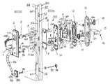
- FIG. 1is an exploded perspective view of the thumb operated door lock.
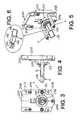
- FIGS. 2A , 2 B and 2 Cshow details of the limited engagement interior hub collar and limited engagement drive spindle shown in FIG. 1 .
- FIG. 3is a door-side rear elevational view of the exterior latch withdrawal assembly and the limited engagement drive spindle shown in FIGS. 1 and 2 .
- FIG. 4is a right side elevational view of the exterior latch withdrawal assembly and limited engagement drive spindle, shown in FIGS. 1-3 .
- FIG. 5is a perspective view showing the back, right side and top of the exterior latch withdrawal assembly and limited engagement drive spindle shown in FIGS. 3 and 4 .
- FIG. 6is a detail of the limited engagement drive spindle shown in FIGS. 1-5 .
- a multi-point latch and deadbolt system 50is shown mounted in an edge 82 of a door 80 .
- Door 80is pulled shut allowing spring mounted latches 52 to be pushed inward and then to extend outward into receivers in a door jamb from housing 54 of the G-U Hardware Eagle Multi-Point Gear Assembly 18 , as shown, for example, in U.S. Pat. No. 6,389,855.
- a deadboltis extended through opening 56 by turning a key 58 in key lock cylinder 3 or by turning interior locking knob 14 . Extending the deadbolt also operates within the patented assembly 18 to prevent unintended inward movement of the latches, holding the latches 52 in extended position.
- the main body 60 of the latch and deadbolt Multi-Point Gear Assembly 18holds the latch and deadbolt operator for extending and withdrawing a deadbolt through opening 56 .
- Auxiliary upper and lower bodies 62 and 64 and main body 60hold the operator mechanisms for extending, locking and withdrawing the upper, lower and central latches 52 .
- Turnable receiver 66 in main body 60 of assembly 18turns an operator to withdraw latches 52 .
- Turnable receiver 68 in body 60turns an operator in assembly 18 to move the deadbolt out or in through opening 56 .
- assembly 18prevents inward movement of the latches 52 , providing a four-point lock. Withdrawing the deadbolt permits inward movement of the latches 52 by thumb lever 1 or interior lever 15 .
- the assembly 18may be configured so that the deadbolt extension does not prevent inward movement of the latches. Interior lever 15 simultaneously withdraws the latches and deadbolt.
- An exterior escutcheon plate 2 and grip handle assemblyis mounted on the outside 84 of door 80 .
- a thumb lever 1is mounted directly above the fixed grip handle 86 .
- Bolt 90extends from the inner side of plate 2 to secure the top of handle 86 .
- the bottom of handle 86is secured to a bottom plate 88 by a long screw 92 , which extends through an interior cup 94 , the door 80 , a sleeve 96 and plate 88 . Screw 92 engages nut 98 secured to the bottom of handle 86 .
- Thumb lever 1has an extension 100 which extends through opening 101 in plate 2 . Thumb lever 1 is pivoted on a pin extending through a hole in extension 100 on the inside of plate 2 .
- a linear to rotary motion converterfor example a rack connected to extension 100 and a pinion connected to the rack, turn the limited engagement drive spindle 4 and its extended tongue 104 when thumb lever 1 is depressed.
- Tongue 104fits diagonally through the square opening 67 of receiver 66 , and a square cross section base 190 of spindle 104 fits in the square opening 67 in receiver 66 to turn the operator in assembly 18 for withdrawing latches 52 .
- Tongue 102extends from lock cylinder 3 through the rectangular opening in receiver 68 and turns the receiver to move the deadbolt operator in assembly 18 to extend or withdraw the deadbolt.
- Key cylinder mounting screw supports 5 and lever drive hub screw supports 6fit through the door 80 and through openings 106 and recesses 108 in the main body 60 of assembly 18 to receive interior mounting screws 8 , which secure interior mounting support plate 7 and exterior escutcheon plate 2 to each other and to the door, strengthening the door.
- Limited engagement interior hub collar 9has a square cross section extension 119 which fits in the square opening 121 in interior latch operating lever 15 and is held there by lever mounting set screw 16 .
- collar 9has a main cylindrical body 120 with outer part 122 and inner part 124 separated by a flange 126 .
- Flange 126 on collar 9is received in complementary recess 127 in plate 10 .
- the body 120 and its extension and outer and inner partsrotate together.
- the outer part 122has a generally radially opposite sectoral FIG. 8 shaped recess 128 which receives tongue 104 of limited engagement drive spindle 4 .
- the sectoral recessespermit interior lever 15 to be raised, turning the body 120 so that radial faces of the recess 128 are spaced from tongue 104 to prevent latches 52 to be withdrawn by moving thumb lever 1 .
- thumb lever 1is disabled when interior lever 15 is raised.
- Sectoral recess 128prevent turning of the element 120 by the thumb lever 1 sufficiently to raise plate 160 and withdraw the deadbolt.
- Diametrically opposite slots 129 in the cylindrical body inner part 124receive projections 132 , 142 which extend inward from rotating elements 130 and 140 in interior simultaneous retraction assembly 11 .
- Assembly 11has two plates, interior simultaneous retraction inside base plate 10 and interior simultaneous retraction outside base plate 12 . Plates 10 and 12 are held together by lugs 152 fitted into slots 154 . Short assembly screws 17 are connected through openings in the plates 10 and 12 to threaded openings or nuts in interior mounting support plate 7 to hold plates 10 and 12 assembled on the support plate 7 .
- Element 130has a segmental gear 134 .
- Gear 134engages a gear on an axle (not shown) extending between large openings 133 and 135 in plates 10 and 12 to provide smooth operation of the interior simultaneous retraction assembly 11 .
- Element 130 , sliding plate 160 and lever 169turn connector 170 , tongue 102 and receiver 68 to withdraw the deadbolt, if it is extended, when the interior operating lever 15 is turned to withdraw latches 52 .
- Upper edges 136 of element 130engage lower edges 162 of sliding plate 160 and lift the sliding plate when lever 15 turns element 130 .
- Upper curved edges 164 of sliding plate 160engage edges 166 of lock turner lever 169 in interior simultaneous retraction assembly 11 .
- element 130is rotated.
- One of its edges 136lifts an edge 162 and sliding plate 160 .
- An upper edge 164 of sliding plate 160moves an edge 166 and lock lever 169 to simultaneously turn receiver 68 to withdraw the deadbolt, as lever 15 withdraws latches 52 .
- Springs 180keep sliding plate 160 in contact with element 130 and keep element 130 level.
- Springs 182 on element 140keep element 140 centered, keeping interior operating lever 15 horizontal and latches 52 in outward positions.
- Square opening 168 of lock lever 169 in assembly 11engages the square extension 172 of lock connector 170 .
- the same square extension 172is received in the square axial opening 184 in the interior locking knob 14 .
- the outer facing end 174 of connector 170has a rectangular slot opening 178 to receive tongue 102 which extends from key lock cylinder through turnable lock operating receiver 68 and into opening 178 .
- the limited engagement drive spindle 4has a square cross section base 190 which is mounted in a turning mechanism 192 .
- the turning mechanismconverts the linear arcuate motions of the thumb lever 1 and its extension 100 to rotary motion for turning drive spindle 4 .
- the linear to rotary motionmay be provided by a rack gear attached to the inner end of the thumb lever extension 100 and a pinion gear having a central recess for receiving end 194 of spindle 4 .
- Spring clip 196fits in groove 198 of the spindle to hold the spindle in the turning assembly 192 .
- Lever drive hub screw supports 6are shown connected to the casing 200 , which is attached to outside exterior escutcheon plate 2 with screws 8 .
- Casing 200has a body 202 and a cover 204 which is attached to the body by screws 206 .
- Ears 208 on the body 202have openings 210 for screws to secure the turning assembly 192 to plate 2 .
Landscapes
- Engineering & Computer Science (AREA)
- Mechanical Engineering (AREA)
- Business, Economics & Management (AREA)
- Emergency Management (AREA)
- Structural Engineering (AREA)
- Lock And Its Accessories (AREA)
Abstract
Description
This application claims the benefit of U.S. Provisional Application No. 61/205,462, filed Jan. 16, 2009, which is hereby incorporated by reference in its entirety as if fully set forth herein.
The disclosures of U.S. Pat. Nos. 6,327,881 and 6,389,855 are hereby incorporated by reference in their entirety as if fully set forth herein.
The new grip-set uses the traditional thumb-operated exterior thumb lever, which retracts the multi-point latching gear. The in-door latch and deadbolt gear operators are already patented by G-U Germany. The new total system and the new elements are the subject of this invention.
Features of the invention include:
1. Multi-point door locking system with thumb operated retraction
2. Simultaneous retraction of the deadbolt when the interior lever is operated (panic mode)
3. Reduced warping of exterior entry door panels
4. Independent deadbolt operation from multi-point gear operation.
These and further and other objects and features of the invention are apparent in the disclosure, which includes the above and ongoing written specification, with the drawings.
InFIGS. 1 and 2A ,2B and2C, a multi-point latch anddeadbolt system 50 is shown mounted in anedge 82 of adoor 80.Door 80 is pulled shut allowing spring mountedlatches 52 to be pushed inward and then to extend outward into receivers in a door jamb fromhousing 54 of the G-U Hardware Eagle Multi-Point Gear Assembly18, as shown, for example, in U.S. Pat. No. 6,389,855. A deadbolt is extended through opening56 by turning akey 58 inkey lock cylinder 3 or by turning interior locking knob14. Extending the deadbolt also operates within the patentedassembly 18 to prevent unintended inward movement of the latches, holding thelatches 52 in extended position.
Themain body 60 of the latch and deadbolt Multi-Point Gear Assembly18 holds the latch and deadbolt operator for extending and withdrawing a deadbolt through opening56. Auxiliary upper andlower bodies main body 60 hold the operator mechanisms for extending, locking and withdrawing the upper, lower andcentral latches 52.
Turnable receiver66 inmain body 60 ofassembly 18 turns an operator to withdrawlatches 52.Turnable receiver 68 inbody 60 turns an operator inassembly 18 to move the deadbolt out or in through opening56. When the deadbolt is extended,assembly 18 prevents inward movement of thelatches 52, providing a four-point lock. Withdrawing the deadbolt permits inward movement of thelatches 52 by thumb lever1 orinterior lever 15. Theassembly 18 may be configured so that the deadbolt extension does not prevent inward movement of the latches. Interior lever15 simultaneously withdraws the latches and deadbolt.
Anexterior escutcheon plate 2 and grip handle assembly is mounted on the outside84 ofdoor 80. A thumb lever1 is mounted directly above thefixed grip handle 86. Bolt90 extends from the inner side ofplate 2 to secure the top ofhandle 86. The bottom ofhandle 86 is secured to abottom plate 88 by along screw 92, which extends through aninterior cup 94, thedoor 80, asleeve 96 andplate 88. Screw92 engagesnut 98 secured to the bottom ofhandle 86.
Thumb lever1 has anextension 100 which extends through opening101 inplate 2. Thumb lever1 is pivoted on a pin extending through a hole inextension 100 on the inside ofplate 2. A linear to rotary motion converter, for example a rack connected toextension 100 and a pinion connected to the rack, turn the limitedengagement drive spindle 4 and its extendedtongue 104 when thumb lever1 is depressed.Tongue 104 fits diagonally through the square opening67 of receiver66, and a squarecross section base 190 ofspindle 104 fits in the square opening67 in receiver66 to turn the operator inassembly 18 for withdrawinglatches 52.
Key cylinder mounting screw supports5 and lever drive hub screw supports6 fit through thedoor 80 and throughopenings 106 andrecesses 108 in themain body 60 ofassembly 18 to receiveinterior mounting screws 8, which secure interiormounting support plate 7 andexterior escutcheon plate 2 to each other and to the door, strengthening the door.
Limited engagementinterior hub collar 9 has a squarecross section extension 119 which fits in the square opening121 in interiorlatch operating lever 15 and is held there by levermounting set screw 16.
As shown inFIGS. 2A and 2B ,collar 9 has a maincylindrical body 120 withouter part 122 and inner part124 separated by aflange 126.Flange 126 oncollar 9 is received in complementary recess127 inplate 10. Thebody 120 and its extension and outer and inner parts rotate together. Theouter part 122 has a generally radially opposite sectoralFIG. 8 shaped recess 128 which receivestongue 104 of limitedengagement drive spindle 4. The sectoral recesses permitinterior lever 15 to be raised, turning thebody 120 so that radial faces of therecess 128 are spaced fromtongue 104 to preventlatches 52 to be withdrawn by moving thumb lever1. Thus, thumb lever1 is disabled wheninterior lever 15 is raised.Sectoral recess 128 prevent turning of theelement 120 by the thumb lever1 sufficiently to raise plate160 and withdraw the deadbolt.
Diametrically opposite slots129 in the cylindrical body inner part124 receiveprojections 132,142 which extend inward from rotatingelements simultaneous retraction assembly 11.
Springs180 keep sliding plate160 in contact withelement 130 and keepelement 130 level.Springs 182 onelement 140 keepelement 140 centered, keepinginterior operating lever 15 horizontal and latches52 in outward positions.
The outer facingend 174 ofconnector 170 has a rectangular slot opening178 to receivetongue 102 which extends from key lock cylinder through turnablelock operating receiver 68 and into opening178.
As shown inFIGS. 2A-6 , the limitedengagement drive spindle 4 has a squarecross section base 190 which is mounted in aturning mechanism 192. The turning mechanism converts the linear arcuate motions of the thumb lever1 and itsextension 100 to rotary motion for turningdrive spindle 4. The linear to rotary motion may be provided by a rack gear attached to the inner end of thethumb lever extension 100 and a pinion gear having a central recess for receiving end194 ofspindle 4.Spring clip 196 fits in groove198 of the spindle to hold the spindle in the turningassembly 192. Lever drive hub screw supports6 are shown connected to thecasing 200, which is attached to outsideexterior escutcheon plate 2 withscrews 8.
Casing200 has abody 202 and acover 204 which is attached to the body by screws206.Ears 208 on thebody 202 haveopenings 210 for screws to secure the turningassembly 192 toplate 2.
In the drawings, the following numbers refer to the following elements.
| Item Number | Description |
| 1 | |
| 2 | Exterior Escutcheon Plate & |
| 3 | |
| 4 | Limited |
| 5 | Key Cylinder mounting screw supports |
| 6 | Lever Drive Hub screw supports |
| 7 | Interior |
| 8 | |
| 9 | Limited Engagement |
| 10 | Interior Simultaneous Retraction Inside |
| 11 | Interior |
| 12 | Interior Simultaneous Retraction |
| 13 | Interior Escutcheon Plate |
| 14 | Interior |
| 15 | |
| 16 | Lever Mounting Set- |
| 17 | Interior Simultaneous Retraction assembly screws |
| 18 | G-U Hardware Eagle Multi-Point Door Gear Assembly |
While the invention has been described with reference to specific embodiments, modifications and variations of the invention may be constructed without departing from the scope of the invention.
Claims (8)
1. A thumb operated door lock apparatus for an entry door comprising:
an in-door housing having door latches and a deadbolt,
a first turnable receiver in the housing for operating the deadbolt,
a second turnable receiver in the housing for operating the latches,
an outer escutcheon plate and a grip handle for mounting on the outside of the entry door,
an inner mounting support plate for mounting inside the entry door opposite the outer escutcheon plate,
screws extending through the inner mounting support plate, through the door, through the in-door housing and into the outer escutcheon plate for holding the inner plate and the outer escutcheon plate and grip handle tight against the entry door for strengthening the entry door,
a key cylinder mounted between the outer escutcheon plate and the in-door housing, the key cylinder having a first turnable tongue extending through the first receiver for turning the first receiver and operating the deadbolt,
a thumb lever extending outward from an opening in the outer escutcheon plate,
an extension on the thumb lever extending inward through the opening,
a horizontal pin extending through a hole in the extension for allowing the thumb lever and extension to pivot around the pin,
a motion converter connected to the extension for converting up and down motion of an end portion of the extension to a rotary motion,
a second turnable tongue extending inward from the motion converter through the second receiver,
first and second base plates connected to the inner mounting support plate,
a slide plate mounted between the base plates,
a slide operator mounted between the base plates,
a first connector mounted between the base plates and receiving the first tongue,
a second connector mounted between the base plates for receiving the second tongue,
an interior escutcheon plate mounted on the base plates,
an interior locking knob mounted on the first connector,
an interior operating lever mounted on the second connector, for turning the slide operator mounted on the second connector for lifting the slide plate,
a lock lever mounted on the first connector and operably connected to the slide plate for turning the first connector and operating the deadbolt when the slide plate is lifted by turning the interior operating lever.
2. The apparatus ofclaim 1 , wherein extension of the deadbolt prevents inward movement of the latches.
3. The apparatus ofclaim 1 , wherein extension of the deadbolt is independent of operation of the latches.
4. The apparatus ofclaim 1 , wherein the second connector has aFIG. 8 shaped segmented opening for receiving the second tongue, wherein movement of the interior operating lever turns the second connector for separating sides of the segmented opening away from the second tongue and preventing movement of the second connector by the second tongue.
5. The apparatus ofclaim 1 , wherein the second connector has a first part which extends through the slide operator into the interior lever.
6. The apparatus ofclaim 5 , wherein the first part of the second connector has opposite longitudinal grooves and wherein the slide operator has inward extensions fitting in the grooves for turning the slide operator with the second connector.
7. The apparatus ofclaim 6 , further comprising springs mounting between the base plates for moving the slide plate downward against the slide operator.
8. The apparatus ofclaim 6 , further comprising a ring mounted on the first part of the second connector between the interior escutcheon plate and one of the base plates, the ring having inward extensions fitted in the opposite grooves and springs connected to the ring for returning the interior operating lever to horizontal position.
Priority Applications (1)
| Application Number | Priority Date | Filing Date | Title |
|---|---|---|---|
| US12/657,375US8161780B1 (en) | 2009-01-16 | 2010-01-19 | Thumb operated door lock assembly |
Applications Claiming Priority (2)
| Application Number | Priority Date | Filing Date | Title |
|---|---|---|---|
| US20546209P | 2009-01-16 | 2009-01-16 | |
| US12/657,375US8161780B1 (en) | 2009-01-16 | 2010-01-19 | Thumb operated door lock assembly |
Publications (1)
| Publication Number | Publication Date |
|---|---|
| US8161780B1true US8161780B1 (en) | 2012-04-24 |
Family
ID=45953389
Family Applications (1)
| Application Number | Title | Priority Date | Filing Date |
|---|---|---|---|
| US12/657,375ActiveUS8161780B1 (en) | 2009-01-16 | 2010-01-19 | Thumb operated door lock assembly |
Country Status (1)
| Country | Link |
|---|---|
| US (1) | US8161780B1 (en) |
Cited By (31)
| Publication number | Priority date | Publication date | Assignee | Title |
|---|---|---|---|---|
| US20110314877A1 (en)* | 2010-06-29 | 2011-12-29 | Guan-Chen Fang | Locking Assembly for a Door |
| US20110314876A1 (en)* | 2010-06-29 | 2011-12-29 | Guan-Chen Fang | Locking Assembly for a Door |
| CN102817498A (en)* | 2012-08-24 | 2012-12-12 | 无锡格瑞特金属制品有限公司 | Escape fire-proof lock |
| US20130000364A1 (en)* | 2011-06-30 | 2013-01-03 | Tsung-Chung Huang | Mortise lock |
| CN103001125A (en)* | 2012-12-07 | 2013-03-27 | 益和电气集团股份有限公司 | Novel switching cabinet |
| CN102995983A (en)* | 2012-12-07 | 2013-03-27 | 益和电气集团股份有限公司 | Novel door lock structure |
| US20130291606A1 (en)* | 2012-05-07 | 2013-11-07 | Remi Emiel Van Parys | Panic lock |
| US20140084601A1 (en)* | 2011-05-09 | 2014-03-27 | Stendals El Ab | Shaft arrangement for a locking device and a locking device |
| US20160083976A1 (en)* | 2014-09-23 | 2016-03-24 | Amesbury Group, Inc. | Entry door latch actuator system |
| US9388611B2 (en)* | 2012-01-03 | 2016-07-12 | Hoppe Holding Ag | Multi-point lock having a flush-mount cylinder |
| US20160340930A1 (en)* | 2015-05-21 | 2016-11-24 | Yale Security Inc. | Escutcheon mounting plate |
| US10662675B2 (en) | 2017-04-18 | 2020-05-26 | Amesbury Group, Inc. | Modular electronic deadbolt systems |
| US10669755B2 (en) | 2018-03-22 | 2020-06-02 | Pella Corporation | Multipoint locks and associated systems and methods |
| US10760303B2 (en) | 2016-03-28 | 2020-09-01 | Hoppe Holding Ag | Multi-point lock with single actuation and mishandling device and self-aligning engagement |
| US10808424B2 (en) | 2017-05-01 | 2020-10-20 | Amesbury Group, Inc. | Modular multi-point lock |
| US10876324B2 (en) | 2017-01-19 | 2020-12-29 | Endura Products, Llc | Multipoint lock |
| US10968661B2 (en) | 2016-08-17 | 2021-04-06 | Amesbury Group, Inc. | Locking system having an electronic deadbolt |
| US11066850B2 (en) | 2017-07-25 | 2021-07-20 | Amesbury Group, Inc | Access handle for sliding doors |
| US11111698B2 (en) | 2016-12-05 | 2021-09-07 | Endura Products, Llc | Multipoint lock |
| SE2050711A1 (en)* | 2020-06-12 | 2021-12-13 | Stendals El Ab | Adapter for a locking device |
| US20220042346A1 (en)* | 2019-09-11 | 2022-02-10 | Carrier Corporation | Hub assembly for door handle |
| US11359413B2 (en)* | 2019-10-17 | 2022-06-14 | S.P.E.P. Acquisition Corp. | Expansion adjusting dual action door latch assembly |
| US11441333B2 (en) | 2018-03-12 | 2022-09-13 | Amesbury Group, Inc. | Electronic deadbolt systems |
| US20220362426A1 (en)* | 2020-09-04 | 2022-11-17 | Microlumix Llc | Decontamination of germs on human touch points |
| US11661771B2 (en) | 2018-11-13 | 2023-05-30 | Amesbury Group, Inc. | Electronic drive for door locks |
| US11746565B2 (en) | 2019-05-01 | 2023-09-05 | Endura Products, Llc | Multipoint lock assembly for a swinging door panel |
| US11834866B2 (en) | 2018-11-06 | 2023-12-05 | Amesbury Group, Inc. | Flexible coupling for electronic deadbolt systems |
| USD1036962S1 (en)* | 2022-07-29 | 2024-07-30 | Assa Abloy Americas Residential Inc. | Handleset |
| USD1041287S1 (en)* | 2022-03-21 | 2024-09-10 | Qiang Chen | Electronic handleset |
| USD1041288S1 (en)* | 2022-03-22 | 2024-09-10 | Qiang Chen | Handleset |
| USD1042082S1 (en)* | 2022-11-22 | 2024-09-17 | Assa Abloy Americas Residential Inc. | Handleset |
Citations (44)
| Publication number | Priority date | Publication date | Assignee | Title |
|---|---|---|---|---|
| US3390558A (en)* | 1965-08-09 | 1968-07-02 | Schlage Lock Co | High security lock |
| US4052092A (en)* | 1976-11-19 | 1977-10-04 | Emhart Industries, Inc. | Latch operating device including operating and latch connection improvements |
| US4156541A (en)* | 1977-08-22 | 1979-05-29 | Kysor Industrial Corporation | Lock assembly |
| US4418552A (en)* | 1979-10-22 | 1983-12-06 | Nolin Roger J | Simultaneously locking and unlocking dead bolt and lock latch with panic unlocking |
| US4709565A (en)* | 1986-10-28 | 1987-12-01 | Lin Jui C | United opening device for a double-locked door |
| US4838053A (en)* | 1988-03-21 | 1989-06-13 | Richard Shen | Heavy-duty panic proof lock unit |
| GB2229488A (en) | 1989-03-04 | 1990-09-26 | Abt Hardware Limited | Multipoint lock |
| US4979767A (en)* | 1990-01-08 | 1990-12-25 | Taiwan Fu Hsing Industry Co., Ltd. | Opening device for a double lock |
| US4999950A (en) | 1988-03-11 | 1991-03-19 | Andersen Corporation | Inwardly swinging hinged door assembly |
| US5161837A (en)* | 1991-07-23 | 1992-11-10 | Thomas Industries Inc., Builders Brass Works Div. | Rod and case assembly and panic exit device |
| US5184852A (en)* | 1991-07-23 | 1993-02-09 | Thomas Industries Inc., Builders Brass Works Division | Rod and case assembly |
| US5290077A (en) | 1992-01-14 | 1994-03-01 | W&F Manufacturing, Inc. | Multipoint door lock assembly |
| US5498038A (en) | 1993-02-16 | 1996-03-12 | Marvin Lumber And Cedar Co. | Multi-point door lock system |
| US5611227A (en) | 1996-06-27 | 1997-03-18 | Emhart Inc. | Handleset with thumb piece and rack |
| US5655393A (en)* | 1995-03-07 | 1997-08-12 | Tong-Lung Metal Industry Co., Ltd. | Door lock set with simultaneously retractable deadbolt and latch |
| US5697654A (en) | 1995-02-06 | 1997-12-16 | Macdonald; Edwin A. | Security door assembly |
| US5787741A (en)* | 1997-08-28 | 1998-08-04 | Shen; Mu-Lin | Cartridge assembly of a panic proof lock |
| US5820173A (en) | 1992-10-30 | 1998-10-13 | Fuller; Mark Weston | Lock mechanism |
| US5881585A (en)* | 1997-03-31 | 1999-03-16 | Hyundae Metal Co., Ltd. | Apparatus for simultaneously unlocking a door lock and a dead bolt |
| US5911763A (en) | 1998-01-12 | 1999-06-15 | Quesada; Flavio R. | Three point lock mechanism |
| WO2000075466A1 (en) | 1999-06-09 | 2000-12-14 | Therma-Tru Corporation | Thumb-operated multilatch door lock |
| US6209931B1 (en) | 1999-02-22 | 2001-04-03 | Newell Operating Company | Multi-point door locking system |
| WO2001059237A2 (en) | 2000-02-10 | 2001-08-16 | Sargent Manufacturing Company | Multipoint mortise lock |
| US6327881B1 (en) | 1997-10-24 | 2001-12-11 | Gretsch-Unitas Gmbh Baubeschlage | Locking device |
| US6386602B1 (en)* | 2000-10-26 | 2002-05-14 | Tawain Fu Hsing Industrial Co., Ltd. | Lever handle structure for lock |
| US6389855B2 (en)* | 1996-03-26 | 2002-05-21 | Gretsch-Unitas Gmbh Baubeschlage | Locking device for a door, window or the like |
| US6564596B2 (en) | 2001-10-12 | 2003-05-20 | Taiwan Fu Hsing Industrial Co., Ltd. | Door lock assembly with multiple latch devices |
| US20040004359A1 (en) | 2002-07-02 | 2004-01-08 | George Wartian | Door latch mechanism |
| US20050092040A1 (en)* | 2003-10-29 | 2005-05-05 | Ya-Yun Chuang | Door lock with a coupling mechanism for simultaneous movement of latch bolt and deadbolt |
| EP1533452A2 (en) | 2003-11-18 | 2005-05-25 | Assa Abloy Financial Services AB | A multipoint lock |
| US20050262906A1 (en)* | 2004-02-17 | 2005-12-01 | Oscar Romero | Chassis for a lock set |
| US20060053846A1 (en)* | 2004-09-10 | 2006-03-16 | Lan-Shi Huang | Control mechanism for lock assembly |
| US7025394B1 (en) | 2005-03-23 | 2006-04-11 | Hunt Harry C | Lock system for integrating into an entry door having a vertical expanse and providing simultaneous multi-point locking along the vertical expanse of the entry door |
| US7036856B2 (en)* | 2003-03-05 | 2006-05-02 | Schlage Lock Company | Spring cage assembly |
| US20070080541A1 (en) | 2005-10-06 | 2007-04-12 | W & F Manufacturing | Lever actuated door latch operator |
| US20070137267A1 (en)* | 2005-12-16 | 2007-06-21 | Newfrey Llc | Lock set to deadbolt interlock |
| WO2007082022A2 (en) | 2006-01-11 | 2007-07-19 | Stanley Chung | Multi point door lock assembly |
| US7287787B1 (en) | 2007-01-24 | 2007-10-30 | Sargent Manufacturing Company | Linear thumb-piece actuation latch mechanism |
| US7290808B2 (en)* | 2004-01-16 | 2007-11-06 | Schlage Lock Company | Adjustable door handle |
| US7364212B1 (en)* | 2006-11-28 | 2008-04-29 | Eversafety Precision Industry (Tianjin) Co., Ltd. | Door lock |
| US7404306B2 (en) | 2004-01-29 | 2008-07-29 | Newell Operating Company | Multi-point door lock and offset extension bolt assembly |
| US7421868B2 (en) | 2003-03-19 | 2008-09-09 | Mul-T-Lock Technologies Ltd. | Enhanced extendable multipoint lock |
| US7523971B2 (en)* | 2005-06-10 | 2009-04-28 | Newfrey, Llc | Spindle assembly with captive spring for use in a door handle assembly |
| US7748759B2 (en)* | 2006-06-16 | 2010-07-06 | Tong-Lung Metal Industry Co., Ltd. | Door lock having an unlocking mechanism for simultaneously unlatching latch-bolt and deadbolt mechanisms |
- 2010
- 2010-01-19USUS12/657,375patent/US8161780B1/enactiveActive
Patent Citations (49)
| Publication number | Priority date | Publication date | Assignee | Title |
|---|---|---|---|---|
| US3390558A (en)* | 1965-08-09 | 1968-07-02 | Schlage Lock Co | High security lock |
| US4052092A (en)* | 1976-11-19 | 1977-10-04 | Emhart Industries, Inc. | Latch operating device including operating and latch connection improvements |
| US4156541A (en)* | 1977-08-22 | 1979-05-29 | Kysor Industrial Corporation | Lock assembly |
| US4418552A (en)* | 1979-10-22 | 1983-12-06 | Nolin Roger J | Simultaneously locking and unlocking dead bolt and lock latch with panic unlocking |
| US4709565A (en)* | 1986-10-28 | 1987-12-01 | Lin Jui C | United opening device for a double-locked door |
| US4999950A (en) | 1988-03-11 | 1991-03-19 | Andersen Corporation | Inwardly swinging hinged door assembly |
| US4838053A (en)* | 1988-03-21 | 1989-06-13 | Richard Shen | Heavy-duty panic proof lock unit |
| GB2229488A (en) | 1989-03-04 | 1990-09-26 | Abt Hardware Limited | Multipoint lock |
| US4979767A (en)* | 1990-01-08 | 1990-12-25 | Taiwan Fu Hsing Industry Co., Ltd. | Opening device for a double lock |
| US5161837A (en)* | 1991-07-23 | 1992-11-10 | Thomas Industries Inc., Builders Brass Works Div. | Rod and case assembly and panic exit device |
| US5184852A (en)* | 1991-07-23 | 1993-02-09 | Thomas Industries Inc., Builders Brass Works Division | Rod and case assembly |
| US5290077A (en) | 1992-01-14 | 1994-03-01 | W&F Manufacturing, Inc. | Multipoint door lock assembly |
| US5820173A (en) | 1992-10-30 | 1998-10-13 | Fuller; Mark Weston | Lock mechanism |
| US5498038A (en) | 1993-02-16 | 1996-03-12 | Marvin Lumber And Cedar Co. | Multi-point door lock system |
| US5697654A (en) | 1995-02-06 | 1997-12-16 | Macdonald; Edwin A. | Security door assembly |
| US5915764A (en) | 1995-02-06 | 1999-06-29 | Macdonald; Edwin A. | Security door assembly |
| US5655393A (en)* | 1995-03-07 | 1997-08-12 | Tong-Lung Metal Industry Co., Ltd. | Door lock set with simultaneously retractable deadbolt and latch |
| US6389855B2 (en)* | 1996-03-26 | 2002-05-21 | Gretsch-Unitas Gmbh Baubeschlage | Locking device for a door, window or the like |
| US5611227A (en) | 1996-06-27 | 1997-03-18 | Emhart Inc. | Handleset with thumb piece and rack |
| US5881585A (en)* | 1997-03-31 | 1999-03-16 | Hyundae Metal Co., Ltd. | Apparatus for simultaneously unlocking a door lock and a dead bolt |
| US5787741A (en)* | 1997-08-28 | 1998-08-04 | Shen; Mu-Lin | Cartridge assembly of a panic proof lock |
| US6327881B1 (en) | 1997-10-24 | 2001-12-11 | Gretsch-Unitas Gmbh Baubeschlage | Locking device |
| US5911763A (en) | 1998-01-12 | 1999-06-15 | Quesada; Flavio R. | Three point lock mechanism |
| US6209931B1 (en) | 1999-02-22 | 2001-04-03 | Newell Operating Company | Multi-point door locking system |
| WO2000075466A1 (en) | 1999-06-09 | 2000-12-14 | Therma-Tru Corporation | Thumb-operated multilatch door lock |
| US6257030B1 (en) | 1999-06-09 | 2001-07-10 | Therma-Tru Corporation | Thumb-operated multilatch door lock |
| WO2001059237A2 (en) | 2000-02-10 | 2001-08-16 | Sargent Manufacturing Company | Multipoint mortise lock |
| US6282929B1 (en) | 2000-02-10 | 2001-09-04 | Sargent Manufacturing Company | Multipoint mortise lock |
| US6386602B1 (en)* | 2000-10-26 | 2002-05-14 | Tawain Fu Hsing Industrial Co., Ltd. | Lever handle structure for lock |
| US6564596B2 (en) | 2001-10-12 | 2003-05-20 | Taiwan Fu Hsing Industrial Co., Ltd. | Door lock assembly with multiple latch devices |
| US20040004359A1 (en) | 2002-07-02 | 2004-01-08 | George Wartian | Door latch mechanism |
| US7036856B2 (en)* | 2003-03-05 | 2006-05-02 | Schlage Lock Company | Spring cage assembly |
| US7421868B2 (en) | 2003-03-19 | 2008-09-09 | Mul-T-Lock Technologies Ltd. | Enhanced extendable multipoint lock |
| US20050092040A1 (en)* | 2003-10-29 | 2005-05-05 | Ya-Yun Chuang | Door lock with a coupling mechanism for simultaneous movement of latch bolt and deadbolt |
| EP1533452A2 (en) | 2003-11-18 | 2005-05-25 | Assa Abloy Financial Services AB | A multipoint lock |
| US7290808B2 (en)* | 2004-01-16 | 2007-11-06 | Schlage Lock Company | Adjustable door handle |
| US20080256994A1 (en) | 2004-01-29 | 2008-10-23 | Newell Operating Company | Multi-Point Door Lock and Offset Extension Bolt Assembly |
| US7404306B2 (en) | 2004-01-29 | 2008-07-29 | Newell Operating Company | Multi-point door lock and offset extension bolt assembly |
| US7257973B2 (en)* | 2004-02-17 | 2007-08-21 | Newfrey, Llc | Chassis for a lock set |
| US20050262906A1 (en)* | 2004-02-17 | 2005-12-01 | Oscar Romero | Chassis for a lock set |
| US20060053846A1 (en)* | 2004-09-10 | 2006-03-16 | Lan-Shi Huang | Control mechanism for lock assembly |
| US7025394B1 (en) | 2005-03-23 | 2006-04-11 | Hunt Harry C | Lock system for integrating into an entry door having a vertical expanse and providing simultaneous multi-point locking along the vertical expanse of the entry door |
| US7523971B2 (en)* | 2005-06-10 | 2009-04-28 | Newfrey, Llc | Spindle assembly with captive spring for use in a door handle assembly |
| US20070080541A1 (en) | 2005-10-06 | 2007-04-12 | W & F Manufacturing | Lever actuated door latch operator |
| US20070137267A1 (en)* | 2005-12-16 | 2007-06-21 | Newfrey Llc | Lock set to deadbolt interlock |
| WO2007082022A2 (en) | 2006-01-11 | 2007-07-19 | Stanley Chung | Multi point door lock assembly |
| US7748759B2 (en)* | 2006-06-16 | 2010-07-06 | Tong-Lung Metal Industry Co., Ltd. | Door lock having an unlocking mechanism for simultaneously unlatching latch-bolt and deadbolt mechanisms |
| US7364212B1 (en)* | 2006-11-28 | 2008-04-29 | Eversafety Precision Industry (Tianjin) Co., Ltd. | Door lock |
| US7287787B1 (en) | 2007-01-24 | 2007-10-30 | Sargent Manufacturing Company | Linear thumb-piece actuation latch mechanism |
Cited By (46)
| Publication number | Priority date | Publication date | Assignee | Title |
|---|---|---|---|---|
| US20110314876A1 (en)* | 2010-06-29 | 2011-12-29 | Guan-Chen Fang | Locking Assembly for a Door |
| US8302437B2 (en)* | 2010-06-29 | 2012-11-06 | Eversafety Precision Industry (Tainjin) Co., Ltd. | Locking assembly for a door |
| US20110314877A1 (en)* | 2010-06-29 | 2011-12-29 | Guan-Chen Fang | Locking Assembly for a Door |
| US9404284B2 (en)* | 2011-05-09 | 2016-08-02 | Stendals El Ab | Shaft arrangement for a locking device and a locking device |
| US20140084601A1 (en)* | 2011-05-09 | 2014-03-27 | Stendals El Ab | Shaft arrangement for a locking device and a locking device |
| US20130000364A1 (en)* | 2011-06-30 | 2013-01-03 | Tsung-Chung Huang | Mortise lock |
| US8881562B2 (en)* | 2011-06-30 | 2014-11-11 | Stanley Security Solutions Taiwan Ltd | Mortise lock |
| US9388611B2 (en)* | 2012-01-03 | 2016-07-12 | Hoppe Holding Ag | Multi-point lock having a flush-mount cylinder |
| US9074391B2 (en)* | 2012-05-07 | 2015-07-07 | Remi Emiel Van Parys | Panic lock |
| US20130291606A1 (en)* | 2012-05-07 | 2013-11-07 | Remi Emiel Van Parys | Panic lock |
| CN102817498A (en)* | 2012-08-24 | 2012-12-12 | 无锡格瑞特金属制品有限公司 | Escape fire-proof lock |
| CN103001125B (en)* | 2012-12-07 | 2015-01-28 | 益和电气集团股份有限公司 | Novel switching cabinet |
| CN102995983A (en)* | 2012-12-07 | 2013-03-27 | 益和电气集团股份有限公司 | Novel door lock structure |
| CN103001125A (en)* | 2012-12-07 | 2013-03-27 | 益和电气集团股份有限公司 | Novel switching cabinet |
| US20160083976A1 (en)* | 2014-09-23 | 2016-03-24 | Amesbury Group, Inc. | Entry door latch actuator system |
| US9605444B2 (en)* | 2014-09-23 | 2017-03-28 | Amesbury Group, Inc. | Entry door latch actuator system |
| US20160340930A1 (en)* | 2015-05-21 | 2016-11-24 | Yale Security Inc. | Escutcheon mounting plate |
| US10161162B2 (en)* | 2015-05-21 | 2018-12-25 | Yale Security Inc. | Escutcheon mounting plate |
| US10760303B2 (en) | 2016-03-28 | 2020-09-01 | Hoppe Holding Ag | Multi-point lock with single actuation and mishandling device and self-aligning engagement |
| US10968661B2 (en) | 2016-08-17 | 2021-04-06 | Amesbury Group, Inc. | Locking system having an electronic deadbolt |
| US11111698B2 (en) | 2016-12-05 | 2021-09-07 | Endura Products, Llc | Multipoint lock |
| US10876324B2 (en) | 2017-01-19 | 2020-12-29 | Endura Products, Llc | Multipoint lock |
| US12104409B2 (en) | 2017-01-19 | 2024-10-01 | Endura Products, Llc | Multipoint lock |
| USD1026613S1 (en) | 2017-01-19 | 2024-05-14 | Endura Products, Llc | Locking device |
| US12146344B2 (en) | 2017-01-19 | 2024-11-19 | Endura Products, Llc | Multipoint lock |
| US11634931B2 (en) | 2017-04-18 | 2023-04-25 | Amesbury Group, Inc. | Modular electronic deadbolt systems |
| US10662675B2 (en) | 2017-04-18 | 2020-05-26 | Amesbury Group, Inc. | Modular electronic deadbolt systems |
| US10808424B2 (en) | 2017-05-01 | 2020-10-20 | Amesbury Group, Inc. | Modular multi-point lock |
| US11066850B2 (en) | 2017-07-25 | 2021-07-20 | Amesbury Group, Inc | Access handle for sliding doors |
| US11441333B2 (en) | 2018-03-12 | 2022-09-13 | Amesbury Group, Inc. | Electronic deadbolt systems |
| US10669755B2 (en) | 2018-03-22 | 2020-06-02 | Pella Corporation | Multipoint locks and associated systems and methods |
| US11834866B2 (en) | 2018-11-06 | 2023-12-05 | Amesbury Group, Inc. | Flexible coupling for electronic deadbolt systems |
| US11661771B2 (en) | 2018-11-13 | 2023-05-30 | Amesbury Group, Inc. | Electronic drive for door locks |
| US12331553B2 (en) | 2019-05-01 | 2025-06-17 | Endura Products, Llc | Multipoint lock assembly for a swinging door panel |
| US11746565B2 (en) | 2019-05-01 | 2023-09-05 | Endura Products, Llc | Multipoint lock assembly for a swinging door panel |
| US12352074B2 (en)* | 2019-09-11 | 2025-07-08 | Honeywell International Inc. | Hub assembly for door handle |
| US20220042346A1 (en)* | 2019-09-11 | 2022-02-10 | Carrier Corporation | Hub assembly for door handle |
| US11359413B2 (en)* | 2019-10-17 | 2022-06-14 | S.P.E.P. Acquisition Corp. | Expansion adjusting dual action door latch assembly |
| SE545946C2 (en)* | 2020-06-12 | 2024-03-19 | Stendals El Ab | Adapter for a locking device for unlocking by an inner handle in an emergency function |
| SE2050711A1 (en)* | 2020-06-12 | 2021-12-13 | Stendals El Ab | Adapter for a locking device |
| US12151044B2 (en)* | 2020-09-04 | 2024-11-26 | Microlumix Llc | Decontamination of germs on human touch points |
| US20220362426A1 (en)* | 2020-09-04 | 2022-11-17 | Microlumix Llc | Decontamination of germs on human touch points |
| USD1041287S1 (en)* | 2022-03-21 | 2024-09-10 | Qiang Chen | Electronic handleset |
| USD1041288S1 (en)* | 2022-03-22 | 2024-09-10 | Qiang Chen | Handleset |
| USD1036962S1 (en)* | 2022-07-29 | 2024-07-30 | Assa Abloy Americas Residential Inc. | Handleset |
| USD1042082S1 (en)* | 2022-11-22 | 2024-09-17 | Assa Abloy Americas Residential Inc. | Handleset |
Similar Documents
| Publication | Publication Date | Title |
|---|---|---|
| US8161780B1 (en) | Thumb operated door lock assembly | |
| US4418552A (en) | Simultaneously locking and unlocking dead bolt and lock latch with panic unlocking | |
| CN103608535B (en) | Clutch mechanism for lock assembly | |
| US7866713B2 (en) | Locker structure | |
| US7201030B2 (en) | Gate lock device | |
| US20090025438A1 (en) | Lockset having an electrically operated clutch to control transmission of rotation from an outside handle to an outside spindle | |
| CA2895036C (en) | Recessed lock actuating device for sliding doors | |
| US6857300B1 (en) | Door locking device | |
| US9074391B2 (en) | Panic lock | |
| US8833120B2 (en) | Locking mechanism with integral egress release | |
| US20130175811A1 (en) | Door latch operator apparatus | |
| US4864835A (en) | Door latch mechanism | |
| US9284749B2 (en) | Door lock assembly | |
| CA2615585C (en) | Linear thumb-piece actuation latch mechanism | |
| CA2888909C (en) | Self-lock module | |
| CN112262246B (en) | Electric drive mechanism for operating the lock | |
| US7870772B1 (en) | Exterior lever lock device with a clutch assembly | |
| EP1977062B1 (en) | Multi point door lock assembly | |
| CN201214944Y (en) | Auto-locking sliding window | |
| KR101718993B1 (en) | Doorlock having Lever Cam Direct Driving Type Push-Pull Handle | |
| CA2762882C (en) | Thumb operated door lock assembly | |
| US20230212884A1 (en) | Lock with a clutch driving mechanism | |
| CN212336930U (en) | Anti-cat eye unlocking device | |
| CA2709057C (en) | Locking assembly for a door | |
| EP3115530B1 (en) | Lock for an interior door |
Legal Events
| Date | Code | Title | Description |
|---|---|---|---|
| AS | Assignment | Owner name:G-U HARDWARE, INC., VIRGINIA Free format text:ASSIGNMENT OF ASSIGNORS INTEREST;ASSIGNOR:HUML, JAN M.;REEL/FRAME:024063/0153 Effective date:20100126 | |
| STCF | Information on status: patent grant | Free format text:PATENTED CASE | |
| FPAY | Fee payment | Year of fee payment:4 | |
| MAFP | Maintenance fee payment | Free format text:PAYMENT OF MAINTENANCE FEE, 8TH YR, SMALL ENTITY (ORIGINAL EVENT CODE: M2552); ENTITY STATUS OF PATENT OWNER: SMALL ENTITY Year of fee payment:8 | |
| MAFP | Maintenance fee payment | Free format text:PAYMENT OF MAINTENANCE FEE, 12TH YR, SMALL ENTITY (ORIGINAL EVENT CODE: M2553); ENTITY STATUS OF PATENT OWNER: SMALL ENTITY Year of fee payment:12 |