US8161351B2 - Systems and methods for efficient data storage - Google Patents
Systems and methods for efficient data storageDownload PDFInfo
- Publication number
- US8161351B2 US8161351B2US12/750,654US75065410AUS8161351B2US 8161351 B2US8161351 B2US 8161351B2US 75065410 AUS75065410 AUS 75065410AUS 8161351 B2US8161351 B2US 8161351B2
- Authority
- US
- United States
- Prior art keywords
- data
- codeword
- circuit
- data set
- super sector
- Prior art date
- Legal status (The legal status is an assumption and is not a legal conclusion. Google has not performed a legal analysis and makes no representation as to the accuracy of the status listed.)
- Expired - Fee Related, expires
Links
- 238000013500data storageMethods0.000titleclaimsabstractdescription9
- 238000000034methodMethods0.000titleabstractdescription27
- 238000012545processingMethods0.000claimsdescription32
- 238000010586diagramMethods0.000description7
- 238000000926separation methodMethods0.000description5
- 238000013459approachMethods0.000description2
- 238000003780insertionMethods0.000description2
- 230000037431insertionEffects0.000description2
- 238000012546transferMethods0.000description2
- 238000011144upstream manufacturingMethods0.000description2
- 238000001514detection methodMethods0.000description1
- 230000000694effectsEffects0.000description1
- 238000012986modificationMethods0.000description1
- 230000004048modificationEffects0.000description1
- 230000001360synchronised effectEffects0.000description1
Images


Classifications
- G—PHYSICS
- G11—INFORMATION STORAGE
- G11B—INFORMATION STORAGE BASED ON RELATIVE MOVEMENT BETWEEN RECORD CARRIER AND TRANSDUCER
- G11B20/00—Signal processing not specific to the method of recording or reproducing; Circuits therefor
- G11B20/10—Digital recording or reproducing
- G11B20/12—Formatting, e.g. arrangement of data block or words on the record carriers
- G11B20/1217—Formatting, e.g. arrangement of data block or words on the record carriers on discs
- G—PHYSICS
- G11—INFORMATION STORAGE
- G11B—INFORMATION STORAGE BASED ON RELATIVE MOVEMENT BETWEEN RECORD CARRIER AND TRANSDUCER
- G11B5/00—Recording by magnetisation or demagnetisation of a record carrier; Reproducing by magnetic means; Record carriers therefor
- G11B5/48—Disposition or mounting of heads or head supports relative to record carriers ; arrangements of heads, e.g. for scanning the record carrier to increase the relative speed
- G11B5/58—Disposition or mounting of heads or head supports relative to record carriers ; arrangements of heads, e.g. for scanning the record carrier to increase the relative speed with provision for moving the head for the purpose of maintaining alignment of the head relative to the record carrier during transducing operation, e.g. to compensate for surface irregularities of the latter or for track following
- G11B5/596—Disposition or mounting of heads or head supports relative to record carriers ; arrangements of heads, e.g. for scanning the record carrier to increase the relative speed with provision for moving the head for the purpose of maintaining alignment of the head relative to the record carrier during transducing operation, e.g. to compensate for surface irregularities of the latter or for track following for track following on disks
- G11B5/59633—Servo formatting
- G11B5/59655—Sector, sample or burst servo format
- G—PHYSICS
- G11—INFORMATION STORAGE
- G11B—INFORMATION STORAGE BASED ON RELATIVE MOVEMENT BETWEEN RECORD CARRIER AND TRANSDUCER
- G11B20/00—Signal processing not specific to the method of recording or reproducing; Circuits therefor
- G11B20/10—Digital recording or reproducing
- G11B20/12—Formatting, e.g. arrangement of data block or words on the record carriers
- G11B20/1217—Formatting, e.g. arrangement of data block or words on the record carriers on discs
- G11B2020/1218—Formatting, e.g. arrangement of data block or words on the record carriers on discs wherein the formatting concerns a specific area of the disc
- G11B2020/1222—ECC block, i.e. a block of error correction encoded symbols which includes all parity data needed for decoding
- G—PHYSICS
- G11—INFORMATION STORAGE
- G11B—INFORMATION STORAGE BASED ON RELATIVE MOVEMENT BETWEEN RECORD CARRIER AND TRANSDUCER
- G11B20/00—Signal processing not specific to the method of recording or reproducing; Circuits therefor
- G11B20/10—Digital recording or reproducing
- G11B20/12—Formatting, e.g. arrangement of data block or words on the record carriers
- G11B20/1217—Formatting, e.g. arrangement of data block or words on the record carriers on discs
- G11B2020/1218—Formatting, e.g. arrangement of data block or words on the record carriers on discs wherein the formatting concerns a specific area of the disc
- G11B2020/1232—Formatting, e.g. arrangement of data block or words on the record carriers on discs wherein the formatting concerns a specific area of the disc sector, i.e. the minimal addressable physical data unit
- G—PHYSICS
- G11—INFORMATION STORAGE
- G11B—INFORMATION STORAGE BASED ON RELATIVE MOVEMENT BETWEEN RECORD CARRIER AND TRANSDUCER
- G11B20/00—Signal processing not specific to the method of recording or reproducing; Circuits therefor
- G11B20/10—Digital recording or reproducing
- G11B20/12—Formatting, e.g. arrangement of data block or words on the record carriers
- G11B2020/1264—Formatting, e.g. arrangement of data block or words on the record carriers wherein the formatting concerns a specific kind of data
- G11B2020/1265—Control data, system data or management information, i.e. data used to access or process user data
- G11B2020/1281—Servo information
- G11B2020/1284—Servo information in servo fields which split data fields
- G—PHYSICS
- G11—INFORMATION STORAGE
- G11B—INFORMATION STORAGE BASED ON RELATIVE MOVEMENT BETWEEN RECORD CARRIER AND TRANSDUCER
- G11B20/00—Signal processing not specific to the method of recording or reproducing; Circuits therefor
- G11B20/10—Digital recording or reproducing
- G11B20/12—Formatting, e.g. arrangement of data block or words on the record carriers
- G11B2020/1264—Formatting, e.g. arrangement of data block or words on the record carriers wherein the formatting concerns a specific kind of data
- G11B2020/1289—Formatting of user data
- G—PHYSICS
- G11—INFORMATION STORAGE
- G11B—INFORMATION STORAGE BASED ON RELATIVE MOVEMENT BETWEEN RECORD CARRIER AND TRANSDUCER
- G11B20/00—Signal processing not specific to the method of recording or reproducing; Circuits therefor
- G11B20/10—Digital recording or reproducing
- G11B20/12—Formatting, e.g. arrangement of data block or words on the record carriers
- G11B2020/1291—Formatting, e.g. arrangement of data block or words on the record carriers wherein the formatting serves a specific purpose
- G11B2020/1292—Enhancement of the total storage capacity
- G—PHYSICS
- G11—INFORMATION STORAGE
- G11B—INFORMATION STORAGE BASED ON RELATIVE MOVEMENT BETWEEN RECORD CARRIER AND TRANSDUCER
- G11B20/00—Signal processing not specific to the method of recording or reproducing; Circuits therefor
- G11B20/10—Digital recording or reproducing
- G11B20/18—Error detection or correction; Testing, e.g. of drop-outs
- G11B20/1833—Error detection or correction; Testing, e.g. of drop-outs by adding special lists or symbols to the coded information
- G11B2020/185—Error detection or correction; Testing, e.g. of drop-outs by adding special lists or symbols to the coded information using an low density parity check [LDPC] code
- G—PHYSICS
- G11—INFORMATION STORAGE
- G11B—INFORMATION STORAGE BASED ON RELATIVE MOVEMENT BETWEEN RECORD CARRIER AND TRANSDUCER
- G11B2220/00—Record carriers by type
- G11B2220/20—Disc-shaped record carriers
- G11B2220/25—Disc-shaped record carriers characterised in that the disc is based on a specific recording technology
- G11B2220/2508—Magnetic discs
- G11B2220/2516—Hard disks
Definitions
- the present inventionsare related to storing data, and more particularly to formats, systems and methods for storing data to a storage medium.
- a read channel integrated circuitis a component of a magnetic storage device.
- a read channel componentconverts and encodes data to enable a read/write head assembly to write data to a disk and to subsequently read data back.
- the disktypically includes many tracks containing encoded data that extend around the disk in a radial pattern. Each track includes one or more user data regions as well as intervening servo data regions. The information of the servo data regions is used to position the read/write head assembly in relation to the disks so that the information stored in the user data regions may be retrieved accurately.
- FIG. 1shows a storage medium 100 with two exemplary tracks 150 , 155 indicated as dashed lines.
- the tracksare segregated by servo data written within wedges 160 , 165 .
- These wedgesinclude data and supporting bit patterns 110 that are used for control and synchronization of the read/write head assembly over a desired location on storage medium 100 .
- these wedgesgenerally include a preamble pattern 152 followed by a sector address mark 154 (SAM).
- SAMsector address mark 154
- Sector address mark 154is followed by a Gray code 156
- Gray code 156is followed by burst information 158 .
- burst information 158burst information
- a servo data setmay have two or more fields of burst information.
- a user data region 184is provided between the bit patterns 110 .
- Such user data regions 184include substantial overhead and wasted areas resulting in a reduction in the density of data maintained in the user data region 184 .
- the present inventionsare related to storing data, and more particularly to formats, systems and methods for storing data to a storage medium.
- Various embodiments of the present inventionprovide data storage systems that include a storage medium.
- the storage mediumincludes a first servo data region and a second servo data region separated by a user data region.
- the user data regionincludes at least a portion of a first codeword and a portion of a second codeword that are together associated with a common header data.
- the first codeword and the second codewordare low density parity check encoded codewords.
- the portion of the first codewordis all of the first codeword, and the portion of the second codeword is less than all of the second codeword. In such a case, the remaining part of the second codeword is included in another user data region.
- the data storage systemfurther includes an encoder circuit operable to: receive write data; encode the write data into the first codeword and the second codeword; and combine the portion of the first codeword with the portion of the second codeword and the common header data to form a super sector data set.
- the encoder circuitincludes a low density parity check encoder, and the first codeword and the second codeword are low density parity check encoded codewords.
- the encoder circuitfurther includes a user data region matching circuit that is operable to combine the portion of the first codeword with the portion of the second codeword and the common header data into the super sector data set.
- the super sector data setincludes greater than two times the number of bit periods in the first codeword, and less than the number of bit periods of the user data region.
- the portion of a first codeword, the portion of a second codeword and the common header dataare assembled in a super sector data set.
- the systemsfurther include a decoder circuit operable to: receive the super sector data set; synchronize to the super sector data set using the common header data; divide the super sector data set to yield the portion of the first codeword and the portion of the second codeword; and decode the first codeword and the second codeword to yield the write data.
- the decoder circuitincludes a low density parity check decoder, and the first codeword and the second codeword are low density parity check encoded codewords.
- the codeword boundary matching circuitis operable to: receive a super sector data set having a first codeword, a second codeword and a common header data; and divide the super sector data set to yield the first codeword and the second codeword.
- the data processing circuitoperable to: apply a decoding algorithm to the first codeword to yield a first data set, and apply the decoding algorithm to the second codeword to yield a second data set.
- the first codeword and the second codewordare low density parity check encoded data
- the data processing circuitincludes a low density parity check decoder circuit.
- FIG. 1depicts an existing storage medium including servo data
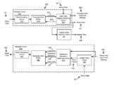
- FIG. 2depicts a storage device including a read channel capable of reading and writing a concatenated user data set in accordance with one or more embodiments of the present invention
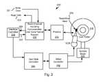
- FIG. 3 adepicts a read channel circuit operable to read and write concatenated user data sets in accordance with various embodiments of the present invention
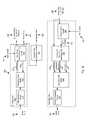
- FIG. 3 bdepicts another read channel circuit operable to read and write concatenated user data sets in accordance with other embodiments of the present invention
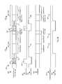
- FIG. 4 ais a timing diagram depicting an exemplary write operation of the read channel of FIG. 3 in accordance with some embodiments of the present invention
- FIG. 4 bis a timing diagram depicting an exemplary read operation of the read channel of FIG. 3 in accordance with some embodiments of the present invention.
- FIG. 5is a flow diagram showing a method for accessing a storage medium using a concatenated user data set in accordance with some embodiments of the present invention.
- the present inventionsare related to storing data, and more particularly to formats, systems and methods for storing data to a storage medium.
- Various embodiments of the present inventionprovide improved format efficiency for user data maintained on a storage medium. Such embodiments provide for concatenating codewords into a super sector data set that is stored to a storage medium.
- the phrase “super sector data set”is used in its broadest sense to mean a data set that includes more than one codeword assembled together with a common header data. Such concatenation, among other things, reduces the amount of overhead associated with maintaining data on a storage medium.
- Various instances of the aforementioned embodimentssupport split codewords allowing for utilization of orphan regions of a storage medium.
- a single preamble field and synchronization patternis included in each user data region to synchronize to the data maintained in the user data region. As such, only a single preamble and synchronization pattern may be used to synchronize to multiple codewords within the user data region.
- the data received from the user data regionis re-assembled into codewords for processing by a read channel circuit.
- Storage system 200may be, for example, a hard disk drive.
- Read channel 210may include support for concatenated user data (i.e., super data sets) consistent with that discussed below in relation to FIG. 3 , and/or may operate consistent with one or more of FIGS. 4-5 .
- read channel 210includes a data detector, such as, for example, a Viterbi algorithm data detector.
- storage system 200includes a preamplifier 270 that amplifies a minute electrical signal received from a read/write head assembly 276 .
- Read/write head assembly 276is disposed in relation to a disk platter 278 .
- Storage system 200also includes an interface controller 220 , a hard disk controller 266 , a motor controller 268 , and a spindle motor 272 .
- Interface controller 220controls addressing and timing of data to/from disk platter 278 .
- the data on disk platter 278consists of groups of magnetic signals that may be detected by read/write head assembly 276 when the assembly is properly positioned over disk platter 278 .
- disk platter 278includes magnetic signals recorded in accordance with a perpendicular recording scheme. In other embodiments of the present invention, disk platter 278 includes magnetic signals recorded in accordance with a longitudinal recording scheme.
- read/write head assembly 276is accurately positioned by motor controller 268 over a desired data track on disk platter 278 .
- Motor controller 268both positions read/write head assembly 276 in relation to disk platter 278 and drives spindle motor 272 by moving read/write head assembly to the proper data track on disk platter 278 under the direction of hard disk controller 266 .
- Spindle motor 272spins disk platter 278 at a determined spin rate (RPMs).
- the sensed magnetic signalsare provided as a continuous, minute analog signal representative of the magnetic data on disk platter 278 .
- This minute analog signalis transferred from read/write head assembly 276 to read channel 210 via preamplifier 270 .
- Preamplifier 270is operable to amplify the minute analog signals accessed from disk platter 278 .
- read channel 210decodes and digitizes the received analog signal to recreate the information originally written to disk platter 278 .
- This datais provided as read data 203 to a receiving circuit.
- a write operationis substantially the opposite of the preceding read operation with write data 201 being provided to read channel module 210 . This data is then encoded and written to disk platter 278 .
- Read channel circuit 205that is operable to read and write concatenated user data sets (i.e., super sector data sets) is shown in accordance with various embodiments of the present invention.
- Read channel circuit 205includes an encoder circuit 233 and a decoder circuit 273 .
- Encoder circuit 233includes a data encoding circuit 213 , an encoded data buffer 219 , and a user data region matching circuit 223 .
- Write data 201is provided to data encoding circuit 213 .
- Write data 201may be received from any data source known in the art, and may be received either via a parallel data bus or via a serial data bus as are known in the art.
- write data 201is received from an upstream processor (not shown).
- Write data 201is assembled by data encoding circuit 213 into codewords that are provided to encoded data buffer 219 .
- data encoding circuit 213is a low density parity check (LDPC) encoder circuit as are known in the art.
- LDPClow density parity check
- data encoding circuit 213provides a series of LDPC codewords to encoded data buffer 219 .
- Such LDPC codewordsinclude portions of write data 201 along with various encoding information as are known in the art.
- the codewordsmay each be four thousand, ninety six user bits plus a number of encoding bits (e.g., parity bits). In some cases, the number of encoding bits may be between forty and four hundred depending upon the robustness of the encoding that is performed.
- Encoded data buffer 219may be any data storage device capable of storing the produced codewords from data encoding circuit 213 until the codewords can be processed and written to a storage medium.
- encoded data buffer 219may be a first in, first out memory that provides portions of stored codewords via a codeword interface 227 to user data region matching circuit 223 upon assertion of a request signal 228 .
- User data region matching circuit 223is operable to assemble two or more codewords into a super sector data set that is provided as an encoded data output 293 to a storage medium.
- Encoded data output 293is provided after write gate signal 287 has been asserted sufficient time for a header data 388 to be written to the storage medium.
- a header data insertion circuit 241provides header data 288 one bit at a time during a header period that directly precedes the writing of encoded data output 293 to the storage medium.
- Header data 288may be any header data known in the art. Providing header data 288 directly preceding encoded data output 293 is controlled based upon assertion of write gate 293 . Header data 288 becomes part of the super sector data set written to the storage medium.
- header data 288includes a preamble and synchronization field that may be used to identify the beginning of the user data and to synchronize to the super sector data set upon read back from the storage medium. Based upon the disclosure provided herein, one of ordinary skill in the art will recognize a variety of header data that may be used in relation to different embodiments of the present invention.
- the number of codewords and portions of codewords assembled into the super sector data setmay be matched to the size of the user data region of the storage medium.
- the following equationrepresents the amount of data incorporated in the super sector data set:
- Number ⁇ ⁇ of ⁇ ⁇ CodewordsSize ⁇ ⁇ of ⁇ ⁇ User ⁇ ⁇ Data ⁇ ⁇ Region - Size ⁇ ⁇ of ⁇ ⁇ Header ⁇ ⁇ Data Size ⁇ ⁇ of ⁇ ⁇ Codewords .
- the size of the user data regionis ten thousand, seven hundred fifty bits
- the size of the header datais one hundred bits
- the size of the codewordsis four thousand, ninety six bits
- the number of codewords calculated by the preceding equationis 2.6.
- the succeeding super sector data setstarts with the header data followed by the next two complete codewords available from encoded data buffer 219 , and a portion of the next codeword from encoded data buffer 219 equivalent to 0.6 of the codeword.
- the remaining portion (i.e., the last 0.4 codeword) of the partial codewordis written after the header data in the succeeding super sector data set.
- User data region matching circuit 223receives a servo gate signal 251 from a servo data processing circuit (not shown) that indicates the location of a user data region relative to intervening servo data regions. Once the super sector data set is assembled as discussed above and servo gate signal 251 indicates the beginning of the user data region, user data region matching circuit 223 asserts a write gate signal 287 and serially provides the assembled super sector data set one bit at a time via encoded data output 293 . This information is provided to a write circuit (not shown) that is responsible for writing the data to the incorporated storage medium.
- Decoder circuit 273includes a header synchronization circuit 252 , a codeword boundary matching circuit 253 , a decoded data buffer 256 , and a data processing circuit 263 .
- Header synchronization circuit 252receives a read data input 296 derived from the storage medium, and synchronizes to the frequency and phase of the received data stream using the preamble and synchronization information included in the header data associated with the received data. This attempt to synchronize begins when servo gate signal 251 indicates that the servo data region has ended and the user data region has begun.
- header synchronization circuit 252asserts a sync found signal 254 indicating that the data received via read data input 296 is valid user data.
- Header synchronization circuit 252may be any circuit known in the art that is capable of synchronizing to a data set derived from a user data region of a storage medium, and asserting a data available indicator signal.
- Codeword boundary matching circuit 253receives read gate input 254 and read data input 296 , and based thereon assembles the received data into full codewords. Thus, for example, where the end of a user data region includes the first portion of a codeword, codeword boundary matching circuit 253 waits to receive the second portion of the codeword from the beginning of the succeeding user data region before providing the completed codeword. Codeword boundary matching circuit 253 uses the information provided via indicator 297 from codeword concatenation table circuit 283 to identify the location of codewords within the data provided via read data input 296 . In some implementations, one or more counters synchronized to sync found signal 254 are used to count bits of codewords and codeword portions derived from a given user data region.
- Codeword boundary matching circuit 253provides codewords or portions of codewords to decoded data buffer 256 , along with a codeword boundary signal 258 indicating a separation between codewords and a data valid signal 257 that is used to indicate that data on any given clock cycle is valid. The combination of these signals are used to write assembled codewords in decoded data buffer 256 . Based upon the disclosure provided herein, one of ordinary skill in the art will recognize other interfaces that may be used to transfer data from codeword boundary matching circuit 253 .
- Decoded data buffer 256may be any data storage device capable of storing the codewords from codeword boundary matching circuit 253 until the codewords can be processed by data processing circuit 263 .
- decoded data buffer 256may be a first in, first out memory that provides codewords from codeword boundary matching circuit 253 to data processing circuit 263 .
- Data processing circuit 263processes the received data and provides read data 203 . Where no processing errors are incurred, read data 203 corresponds to the information originally received as write data 201 .
- Data processing circuit 263may be any circuit known in the art operable to process encoded data derived from a storage medium in an attempt to recover the original data set that was encoded and written to the storage medium.
- data processing circuit 263may be implemented including a decoder circuit as are known in the art that is operable to reverse the encoding applied by data encoding circuit 213 .
- Such a data decoder circuitmay be, but is not limited to an LDPC decoder circuit. Based upon the disclosure provided herein, one of ordinary skill in the art will recognize a myriad of data processing circuits that may be used in relation to different embodiments of the present invention.
- Read channel circuit 306that is operable to read and write concatenated user data sets (i.e., super sector data sets) is shown in accordance with various embodiments of the present invention.
- Read channel circuit 306includes an encoder circuit 334 and a decoder circuit 374 .
- Encoder circuit 334includes a user data matching circuit 324 , a data encoding circuit 314 , and a data write circuit 304 .
- Write data 301is provided to user data region matching circuit 324 .
- Write data 301may be received from any data source known in the art, and may be received either via a parallel data bus or via a serial data bus as are known in the art.
- write data 301is received from an upstream processor (not shown).
- Write data 301is assembled by user data region matching circuit 324 to include enough data to fill an entire user data region on a storage medium.
- the amount of user data assembledis approximately equal to the size of the user data region less the number of encoding bits that are applied to the data and the amount of header data that will precede the data on the storage medium.
- the assembled datais interleaved (i.e., shuffled) by user data matching circuit 324 to reduce the impact of any localized noise on the later recovered data set.
- the assembled and interleaved user datais provided to a data encoding circuit 314 that performs a data encoding on the received user data.
- the data encodingmay be, for example, LDPC encoding as is known in the art.
- Data encoding circuit 314provides the encoded data as a super sector data set to a data write circuit 304 .
- Data write circuit 304receives servo gate 251 from a servo data processing circuit (not shown) that indicates the location of a user data region relative to intervening servo data regions. Once the servo gate 251 is asserted, data write circuit 304 asserts write gate signal 387 .
- a header data insertion circuit 341begins spooling out header data 388 that will become part of the super sector data set on the storage medium.
- data write circuit 304begins writing the encoded data out as encoded data output 394 to the storage medium.
- Header data 388 and encoded data output 394is provided to a downstream write circuit (not shown) that is responsible for writing the data to the incorporated storage medium.
- Decoder circuit 374includes a header synchronization circuit 352 , a detect/decode circuit 353 , and a user data separating circuit 356 .
- Header synchronization circuit 353receives a read data input 396 derived from the storage medium, and synchronizes to the frequency and phase of the received data stream using the preamble and synchronization information included in the header data associated with the received data. This attempt to synchronize begins when servo gate signal 251 indicates that the servo data region has ended and the user data region has begun.
- header synchronization circuit 352asserts a sync found signal 354 indicating that the data received via read data input 396 is valid user data.
- Header synchronization circuit 352may be any circuit known in the art that is capable of synchronizing to a data set derived from a user data region of a storage medium, and asserting a data available indicator signal.
- Data processing circuit 353may be any circuit known in the art operable to process encoded data derived from a storage medium in an attempt to recover the original data set that was encoded and written to the storage medium.
- data processing circuit 353may be implemented including a data detector circuit and a data decoder circuit as are known in the art.
- a data detector circuitmay be, but is not limited to, a Viterbi algorithm detector circuit.
- the decoder circuitmay be, but is not limited to an LDPC decoder circuit.
- data processing circuit 353may be one of the data processing circuits disclosed in U.S.
- data processing circuit 263may be one of the data processing circuits disclosed in U.S. patent application Ser. No. 12/430,927 entitled “Systems and Methods for Hard Decision Assisted Decoding”, and filed Apr. 28, 2009 by Zhong et al. The entirety of the aforementioned reference is incorporated herein by reference for all purposes.
- data processing circuit 263may be one of the data processing circuits disclosed in U.S. patent application Ser. No. 11/341,963 entitled “Systems and Methods for Error Reduction Associated with Information Transfer”, and filed Jan. 26, 2006 by Song et al. The entirety of the aforementioned reference is incorporated herein by reference for all purposes.
- Data processing circuit 353provides a decoded data set to a user data separation circuit 356 .
- User data separation circuit 356is operable to receive the decoded data and to perform any de-interleaving that may be required to assemble the data in the form originally provided as write data 301 . In some cases, such interleaving is applied by data encoding circuit 314 to limit the effects of any localized noise in the data by interleaving or mixing up the user data.
- the de-interleaved datais then provided by user data separating circuit 356 as read data 303 .
- encoded data output 293is a series of data bits corresponding to different regions to be written to a storage medium.
- encoded data output 293is null for a period corresponding to a servo data region 403 that is placed on the storage medium as a reference for where a read/write head assembly exists in relation to the storage medium.
- servo gate signal 251is asserted at a level 425 indicating to user data region matching circuit 223 that no data can be written to the storage medium.
- servo gate signal 251de-asserts.
- user data region matching circuit 223Upon de-assertion of servo gate signal 251 , user data region matching circuit 223 asserts write gate signal 287 at a level 437 while at the same time providing a series of data bits corresponding to user data region 405 .
- user data region matching circuit 223provides bits corresponding to a header 415 .
- Header 415may be used to synchronize to the data written in user data region 405 . This header may include, for example, a preamble followed by a synchronization pattern as is known in the art.
- user data region matching circuit 223begins writing the next codeword.
- user data region matching circuit 223accesses the next code word (i.e., codeword B) from encoded data buffer 219 and provides it in serial as encoded data output 293 .
- user data region matching circuit 223begins accessing the next code word (i.e., codeword C) from encoded data buffer 219 and provides a portion of the codeword as encoded data output 293 .
- codeword Ccode word
- user data region matching circuit 223cuts off the writing of the codeword and subsequently writes a post-amble pattern 491 .
- Such a post-amble patternindicates the end of the codewords that were written to user data region 405 .
- post-amble pattern 491is written, user data region matching circuit 223 de-asserts write gate signal 287 .
- servo gate signal 251is again asserted corresponding to a servo data region 407 that is placed on the storage medium as a reference for where a read/write head assembly exists in relation to the storage medium. Assertion of servo gate signal 251 at a level 427 indicates to user data region matching circuit 223 that no data can be written to the storage medium. Once the servo data region 407 completes, servo gate signal 251 de-asserts.
- user data region matching circuit 223Upon de-assertion of servo gate signal 251 , user data region matching circuit 223 asserts write gate signal 287 at a level 439 while at the same time providing a series of data bits corresponding to a user data region 409 .
- user data region matching circuit 223provides bits corresponding to a header 417 .
- Header 417may be used to synchronize to the data written in user data region 409 . This header may include, for example, a preamble followed by a synchronization pattern as is known in the art.
- User data region matching circuit 223continues writing this codeword until it completes. Once complete, user data region matching circuit 223 accesses the next codeword (i.e., codeword D) from encoded data buffer 219 and provides it as encoded data output 293 to be written to the storage medium. This process continues until near the end of user data region 409 where another post-amble pattern is written and user data region 409 completes.
- codeword Dcodeword D
- Such an approachassembles one or more codewords into a super sector data set that is written to a user data region of the storage medium.
- use of a common header to synchronize to the super sector data setincreases usable bit density of the user data regions.
- a timing diagram 401depicts an exemplary read operation of read channel circuit 205 of FIG. 3 in accordance with some embodiments of the present invention.
- read data input 296is the same series of data bits written to the storage medium in the example of FIG. 4 a .
- read input 296includes servo data 403 read from the storage medium and used to determine the location of a read/write head assembly relative to the storage medium.
- servo gate signal 251is asserted at level 425 indicating to header synchronization circuit 252 that a header from user data region 405 is soon to follow.
- header synchronization circuit 252begins the process of identifying a preamble pattern and synchronization pattern of header 415 . Once header 415 is identified, header synchronization circuit 252 asserts sync found signal 254 at a level 457 .
- codeword boundary matching circuit 253asserts codeword boundary signal 258 (indicated as 463 ) indicating the end of codeword A, and the beginning of the next codeword (i.e., codeword B). Codeword B is then provided as codeword output 259 to decoded data buffer 256 .
- codeword boundary signal 258(indicated as 465 ) is asserted indicating the end of the codeword, and the beginning of the next codeword (i.e., codeword C).
- Codeword Cis then provided as codeword output 259 to decoded data buffer 256 until post-amble 491 is identified and data valid signal 257 is de-asserted by codeword boundary matching circuit 253 .
- the number of received codeword bits(the number of bits in codeword C first part) is less than the number of bits in a codeword. Thus, the count will be maintained and continued in the succeeding user data region 409 .
- Read input 296includes servo data 407 read from the storage medium and used to determine the location of a read/write head assembly relative to the storage medium.
- servo gate signal 251is asserted at level 427 indicating to header synchronization circuit 252 that a header from user data region 409 is soon to follow.
- header synchronization circuit 252begins the process of identifying a preamble pattern and synchronization pattern of header 417 . Once header 417 is identified, header synchronization circuit 252 asserts sync found signal 254 at a level 459 .
- codeword boundary matching circuit 253asserts data valid signal 257 . With data valid signal 257 asserted, the data bits provided as codeword output 259 are stored to decoded data buffer 256 . Codeword boundary matching circuit 253 counts the remaining portion of codeword C (i.e., codeword C second part) at which point codeword boundary matching circuit 253 asserts codeword boundary signal 258 (indicated as 467 ) indicating the end of codeword C, and the beginning of the next codeword (i.e., codeword D). This process continues until the desired read data is obtained from the storage medium.
- FIG. 5a flow diagram 500 showing a method for accessing a storage medium using a concatenated user data set in accordance with some embodiments of the present invention.
- a requesting device or systemmay be, but is not limited to, a processor.
- a read requestmay include an address and/or data range on the storage medium from which data is to be read by a requesting device or system.
- a write requestmay indicate an address and include a data set that is to be written to the storage medium.
- the access and retrieve processesmay be any access and retrieve process known in the art.
- the received dataincludes super sector data set(s) that are received and divided into individual codewords (block 525 ). Such division into individual codewords includes synchronizing using a header data and counting the bits received after the end of the header data. A counter is maintained that counts up to the number of bits per codeword. Where a codeword is spread across a sector boundary, the counter continues until the end of the user data region and continues once bits corresponding to the codeword begin being received in the subsequent user data region.
- the individual codewordsare provided to a data processing circuit where the codewords are decoded to recover the data originally encoded to make the codewords (block 530 ).
- This processingmay include, but is not limited to, one or more iterations through a data detector circuit and a data decoder circuit as is known in the art.
- the aforementioned data detector circuitis a Viterbi algorithm data detector circuit and the data decoder circuit is an LDPC decoder circuit. Based upon the disclosure provided herein, one of ordinary skill in the art will recognize various data processing circuits that may be used in relation to different embodiments of the present invention.
- the decoded codewordsare then provided to the requesting device or system (block 535 ).
- a write requestis received (block 510 )
- the write datais encoded into individual codewords (block 580 ). For example, where a codeword is four thousand, ninety six bits including sixty added encoding bits, four thousand, thirty bits of the write data are encoded to a yield four thousand, ninety six bit codeword.
- the applied encodingis an LDPC encoding and the added encoding bits are parity bits that are calculated and incorporated in the codeword as is known in the art.
- Header datais prepared (block 585 ).
- This header datamay include a preamble pattern and a synchronization pattern. This header data is used upon a read back to synchronize to the data written to the storage medium. Based upon the disclosure provided herein, one of ordinary skill in the art will recognize a variety of header data that may be used in relation to different embodiments of the present invention.
- One or more of the individual codewordsare concatenated to the header data to yield a super sector data set (block 590 ). Where the amount of data to be written is greater than that which can be stored in a single sector, another header data is generated and remaining portions of the data to be written is concatenated to the next header data to yield another super sector data set. The number of header data and codewords that are assembled into super sector data sets is determined based upon the amount of data that is to be written as part of the received write request.
- the prepared super sector data set(s)are written to the selected sector(s) (block 595 ). This may be done using any write process known in the art. In one particular case, this is done by asserting a write gate at a time corresponding to a user data region of a storage medium at which time a read/write head assembly generates a write field in proximity to the storage medium resulting in magnetic information being stored to the storage medium. Based upon the disclosure provided herein, one of ordinary skill in the art will recognize a variety of approaches that may be used to store data to the storage medium.
- a post-amble patternis written to the storage medium (block 597 ). This post-amble pattern is used on a read back to identify the end of the user data.
- the sector(s) where the data was originally writtenare accessed (block 545 ) and the data from the sectors is retrieved (block 550 ).
- the received dataincludes super sector data set(s) that are received and divided into individual codewords (block 555 ). Such division into individual codewords includes synchronizing using a header data and counting the bits received after the end of the header data. A counter is maintained that counts up to the number of bits per codeword.
- the countercontinues until the end of the user data region and continues once bits corresponding to the codeword begin being received in the subsequent user data region. As the counter reaches the number of bits per codeword, an indication of a separation between the codewords is asserted, and the next codeword begins to be assembled from the received data. This process continues until all of the codewords from the retrieved data are separated into individual codewords.
- the individual codewordsare provided to a data processing circuit where the codewords are decoded to recover the data originally encoded to make the codewords (block 560 ). This processing may include, but is not limited to, one or more iterations through a data detector circuit and a data decoder circuit as is known in the art.
- the original datais then overwritten to match the write data associated with the write request (block 565 ). This may include, for example, modifying portions of the data that was read back to match the data provided as part of the write request.
- One or more of the previously written sectors or one or more new sectorsare selected to receive the prepared data set (block 570 ). Once the sector(s) to be written are selected (block 570 ), the processes of blocks 580 through 597 discussed above are performed to write the modified data back to the storage medium.
- the inventionprovides novel systems, devices, methods, formats and arrangements for data storage. While detailed descriptions of one or more embodiments of the invention have been given above, various alternatives, modifications, and equivalents will be apparent to those skilled in the art without varying from the spirit of the invention. Therefore, the above description should not be taken as limiting the scope of the invention, which is defined by the appended claims.
Landscapes
- Engineering & Computer Science (AREA)
- Signal Processing (AREA)
- Signal Processing For Digital Recording And Reproducing (AREA)
Abstract
Description
As an example, where the super sector data set ended on a codeword boundary for the last user data region, the size of the user data region is ten thousand, seven hundred fifty bits, the size of the header data is one hundred bits, and the size of the codewords is four thousand, ninety six bits, the number of codewords calculated by the preceding equation is 2.6. In this case, the succeeding super sector data set starts with the header data followed by the next two complete codewords available from encoded
Number of Remaining Bits=Number of Bits in a Codeword−Number of Received Codeword Bits.
For example, where the total number of bits per codeword is four thousand, ninety six bits, and one thousand of the bits were received from a preceding user data region, the number of remaining bits is three thousand, ninety six bits. Alternatively, where the preceding user data region ended on a codeword boundary, the number of received codeword bits is zero, and the number of remaining bits is four thousand, ninety six bits. Once the number of remaining bits of codeword A have been received, codeword
Claims (26)
Priority Applications (7)
| Application Number | Priority Date | Filing Date | Title |
|---|---|---|---|
| US12/750,654US8161351B2 (en) | 2010-03-30 | 2010-03-30 | Systems and methods for efficient data storage |
| EP10170182AEP2372713A1 (en) | 2010-03-30 | 2010-07-20 | Systems and methods for efficient data storage |
| TW099141736ATWI529705B (en) | 2010-03-30 | 2010-12-01 | Data decoder circuit, data encoder circuit and data processing circuit |
| CN201010599523.4ACN102207908B (en) | 2010-03-30 | 2010-12-22 | system and method for efficient data storage |
| KR1020110008165AKR20110109819A (en) | 2010-03-30 | 2011-01-27 | Systems and Methods for Effective Data Storage |
| JP2011028453AJP2011210353A (en) | 2010-03-30 | 2011-02-14 | System and method for efficient data storage |
| US13/422,742US8321755B2 (en) | 2010-03-30 | 2012-03-16 | Systems and methods for efficient data storage |
Applications Claiming Priority (1)
| Application Number | Priority Date | Filing Date | Title |
|---|---|---|---|
| US12/750,654US8161351B2 (en) | 2010-03-30 | 2010-03-30 | Systems and methods for efficient data storage |
Related Child Applications (1)
| Application Number | Title | Priority Date | Filing Date |
|---|---|---|---|
| US13/422,742ContinuationUS8321755B2 (en) | 2010-03-30 | 2012-03-16 | Systems and methods for efficient data storage |
Publications (2)
| Publication Number | Publication Date |
|---|---|
| US20110246856A1 US20110246856A1 (en) | 2011-10-06 |
| US8161351B2true US8161351B2 (en) | 2012-04-17 |
Family
ID=44175818
Family Applications (2)
| Application Number | Title | Priority Date | Filing Date |
|---|---|---|---|
| US12/750,654Expired - Fee RelatedUS8161351B2 (en) | 2010-03-30 | 2010-03-30 | Systems and methods for efficient data storage |
| US13/422,742ActiveUS8321755B2 (en) | 2010-03-30 | 2012-03-16 | Systems and methods for efficient data storage |
Family Applications After (1)
| Application Number | Title | Priority Date | Filing Date |
|---|---|---|---|
| US13/422,742ActiveUS8321755B2 (en) | 2010-03-30 | 2012-03-16 | Systems and methods for efficient data storage |
Country Status (6)
| Country | Link |
|---|---|
| US (2) | US8161351B2 (en) |
| EP (1) | EP2372713A1 (en) |
| JP (1) | JP2011210353A (en) |
| KR (1) | KR20110109819A (en) |
| CN (1) | CN102207908B (en) |
| TW (1) | TWI529705B (en) |
Families Citing this family (10)
| Publication number | Priority date | Publication date | Assignee | Title |
|---|---|---|---|---|
| US8566666B2 (en)* | 2011-07-11 | 2013-10-22 | Lsi Corporation | Min-sum based non-binary LDPC decoder |
| US8953267B2 (en)* | 2011-11-01 | 2015-02-10 | Lsi Corporation | Digital input detector and associated adaptive power supply |
| GB2509073B (en)* | 2012-12-19 | 2015-05-20 | Broadcom Corp | Methods and apparatus for error coding |
| US9047882B2 (en)* | 2013-08-30 | 2015-06-02 | Lsi Corporation | Systems and methods for multi-level encoding and decoding |
| WO2017059290A1 (en)* | 2015-10-02 | 2017-04-06 | Google Inc. | Peer-to-peer syncable storage system |
| JP6885028B2 (en)* | 2016-11-18 | 2021-06-09 | ソニーグループ株式会社 | Transmission device and transmission method |
| JP2019053802A (en)* | 2017-09-14 | 2019-04-04 | 株式会社東芝 | Storage device and control method |
| US10417088B2 (en)* | 2017-11-09 | 2019-09-17 | International Business Machines Corporation | Data protection techniques for a non-volatile memory array |
| TWI695378B (en)* | 2017-12-15 | 2020-06-01 | 群聯電子股份有限公司 | Bit tagging method, memory controlling circuit unit and memory storage device |
| CN108417181B (en)* | 2018-01-19 | 2021-05-25 | 昆山国显光电有限公司 | Interface definition method and device of driving circuit |
Citations (118)
| Publication number | Priority date | Publication date | Assignee | Title |
|---|---|---|---|---|
| EP0522578A2 (en) | 1991-07-12 | 1993-01-13 | Pioneer Electronic Corporation | Noise removing circuit |
| US5182682A (en) | 1989-09-29 | 1993-01-26 | Seagate Technology, Inc. | Sectored servo disk formatting |
| US5278846A (en) | 1990-06-11 | 1994-01-11 | Matsushita Electric Industrial Co., Ltd. | Digital signal decoder |
| US5278703A (en) | 1991-06-21 | 1994-01-11 | Digital Equipment Corp. | Embedded servo banded format for magnetic disks for use with a data processing system |
| US5325402A (en) | 1991-04-30 | 1994-06-28 | Nec Corporation | Method and arrangement for estimating data sequences transmsitted using Viterbi algorithm |
| US5392299A (en) | 1992-01-15 | 1995-02-21 | E-Systems, Inc. | Triple orthogonally interleaed error correction system |
| EP0631277A3 (en) | 1993-06-22 | 1995-02-22 | Quantum Corp | ID-less data sector format and data controller for disk drive. |
| US5471500A (en) | 1994-03-08 | 1995-11-28 | At&T Ipm Corp. | Soft symbol decoding |
| US5513192A (en) | 1992-08-28 | 1996-04-30 | Sun Microsystems, Inc. | Fault tolerant disk drive system with error detection and correction |
| US5523903A (en) | 1993-12-23 | 1996-06-04 | International Business Machines Corporation | Sector architecture for fixed block disk drive |
| US5550870A (en) | 1994-03-02 | 1996-08-27 | Lucent Technologies Inc. | Viterbi processor |
| US5612964A (en) | 1991-04-08 | 1997-03-18 | Haraszti; Tegze P. | High performance, fault tolerant orthogonal shuffle memory and method |
| US5701314A (en) | 1995-12-21 | 1997-12-23 | Cirrus Logic, Inc. | On-the-fly error correction using thermal asperity erasure pointers from a sampled amplitude read channel in a magnetic disk drive |
| US5710784A (en) | 1993-09-24 | 1998-01-20 | Qualcomm Incorporated | Multirate serial viterbi decoder for code division multiple access system applications |
| US5712861A (en) | 1994-07-12 | 1998-01-27 | Mitsubishi Denki Kabushiki Kaisha | Error correcting method and decoder with improved reliability |
| US5717706A (en) | 1994-03-04 | 1998-02-10 | Sony Corporation | Apparatus and method for detecting signal points using signal point-mapping |
| US5802118A (en) | 1996-07-29 | 1998-09-01 | Cirrus Logic, Inc. | Sub-sampled discrete time read channel for computer storage systems |
| US5818654A (en) | 1994-06-13 | 1998-10-06 | Seagate Technology, Inc. | Apparatus and process for managing defective headerless sectors |
| US5844945A (en) | 1994-04-12 | 1998-12-01 | Goldstar Co., Ltd. | Viterbi decoder for a high definition television |
| US5898710A (en) | 1995-06-06 | 1999-04-27 | Globespan Technologies, Inc. | Implied interleaving, a family of systematic interleavers and deinterleavers |
| US5923713A (en) | 1996-02-28 | 1999-07-13 | Sony Corporation | Viterbi decoder |
| US5978414A (en) | 1996-07-03 | 1999-11-02 | Matsushita Electric Industrial Co., Ltd. | Transmission rate judging unit |
| US5983383A (en) | 1997-01-17 | 1999-11-09 | Qualcom Incorporated | Method and apparatus for transmitting and receiving concatenated code data |
| US5999110A (en)* | 1998-02-17 | 1999-12-07 | International Business Machines Corporation | Defect tolerant binary synchronization mark |
| US6005897A (en) | 1997-12-16 | 1999-12-21 | Mccallister; Ronald D. | Data communication system and method therefor |
| US6023783A (en) | 1996-05-15 | 2000-02-08 | California Institute Of Technology | Hybrid concatenated codes and iterative decoding |
| US6029264A (en) | 1997-04-28 | 2000-02-22 | The Trustees Of Princeton University | System and method for error correcting a received data stream in a concatenated system |
| US6065149A (en) | 1996-11-21 | 2000-05-16 | Matsushita Electric Industrial Co., Ltd. | Error correction device for a communication system |
| US6145110A (en) | 1998-06-22 | 2000-11-07 | Ericsson Inc. | Digital data decoder that derives codeword estimates from soft data |
| US6216249B1 (en) | 1999-03-03 | 2001-04-10 | Cirrus Logic, Inc. | Simplified branch metric for reducing the cost of a trellis sequence detector in a sampled amplitude read channel |
| US6216251B1 (en) | 1999-04-30 | 2001-04-10 | Motorola Inc | On-chip error detection and correction system for an embedded non-volatile memory array and method of operation |
| US6229467B1 (en) | 1999-05-28 | 2001-05-08 | Telefonaktiebolaget Lm Ericsson (Publ) | Correction static errors in a/d-converter |
| US6266795B1 (en) | 1999-05-28 | 2001-07-24 | Lucent Technologies Inc. | Turbo code termination |
| US6317472B1 (en) | 1997-08-07 | 2001-11-13 | Samsung Electronics Co., Ltd. | Viterbi decoder |
| US6351832B1 (en) | 1999-05-28 | 2002-02-26 | Lucent Technologies Inc. | Turbo code symbol interleaver |
| US6377610B1 (en) | 1997-04-25 | 2002-04-23 | Deutsche Telekom Ag | Decoding method and decoding device for a CDMA transmission system for demodulating a received signal available in serial code concatenation |
| US6381726B1 (en) | 1999-01-04 | 2002-04-30 | Maxtor Corporation | Architecture for soft decision decoding of linear block error correcting codes |
| US20020073270A1 (en) | 2000-12-07 | 2002-06-13 | Benson William E. | Headerless split sector format for optical disk drives |
| US6438717B1 (en) | 1999-05-26 | 2002-08-20 | 3Com Corporation | High speed parallel bit error rate tester |
| US6473878B1 (en) | 1999-05-28 | 2002-10-29 | Lucent Technologies Inc. | Serial-concatenated turbo codes |
| US6476989B1 (en) | 1996-07-09 | 2002-11-05 | International Business Machines Corporation | Radial self-propagation pattern generation for disk file servowriting |
| US20030063405A1 (en) | 2001-10-02 | 2003-04-03 | Ming Jin | Method and apparatus for detecting media defects |
| US20030081693A1 (en) | 2001-07-11 | 2003-05-01 | Raghavan Sreen A. | Low complexity high-speed communications transceiver |
| US20030087634A1 (en) | 2001-07-11 | 2003-05-08 | Raghavan Sreen A. | 10165368High-speed multi-channel communications transceiver with inter-channel interference filter |
| US20030112896A1 (en) | 2001-07-11 | 2003-06-19 | Raghavan Sreen A. | Multi-channel communications transceiver |
| US6625775B1 (en) | 1998-12-10 | 2003-09-23 | Samsung Electronics Co., Ltd. | Encoder/decoder with serial concatenated structure in communication system |
| US6657803B1 (en) | 1999-11-22 | 2003-12-02 | Seagate Technology Llc | Method and apparatus for data error recovery using defect threshold detector and viterbi gain |
| US6667701B1 (en)* | 2002-07-16 | 2003-12-23 | Motorola, Inc. | Variable length decoder |
| US6671404B1 (en) | 1997-02-14 | 2003-12-30 | Hewlett-Packard Development Company, L.P. | Method and apparatus for recognizing patterns |
| US20040071206A1 (en) | 2002-08-13 | 2004-04-15 | Fujitsu Limited. | Digital filter adaptively learning filter coefficient |
| US20040098659A1 (en) | 2002-11-18 | 2004-05-20 | Bjerke Bjorn A. | Rate-compatible LDPC codes |
| US6748034B2 (en) | 1997-12-19 | 2004-06-08 | Sony Corporation | Viterbi decoding apparatus and viterbi decoding method |
| US6757862B1 (en) | 2000-08-21 | 2004-06-29 | Handspring, Inc. | Method and apparatus for digital data error correction coding |
| US6785863B2 (en) | 2002-09-18 | 2004-08-31 | Motorola, Inc. | Method and apparatus for generating parity-check bits from a symbol set |
| US6788654B1 (en) | 1998-01-29 | 2004-09-07 | Nippon Hoso Kyokai | Digital data receiver |
| US6810502B2 (en) | 2000-01-28 | 2004-10-26 | Conexant Systems, Inc. | Iteractive decoder employing multiple external code error checks to lower the error floor |
| US20050010855A1 (en) | 2003-07-09 | 2005-01-13 | Itay Lusky | Reduced complexity decoding for trellis coded modulation |
| US20050078399A1 (en) | 2003-10-10 | 2005-04-14 | Seagate Technology Llc | Using data compression to achieve lower linear bit densities on a storage medium |
| US20050111540A1 (en) | 2001-11-21 | 2005-05-26 | David Modrie | Adaptive equalizer operating at a sampling rate asynchronous to the data rate |
| US20050157780A1 (en) | 2003-12-17 | 2005-07-21 | Werner Carl W. | Signaling system with selectively-inhibited adaptive equalization |
| US20050195749A1 (en) | 2004-03-05 | 2005-09-08 | Elmasry George F. | Method and system for capacity analysis for On The Move adhoc wireless packet-switched networks |
| US20050216819A1 (en) | 2004-02-19 | 2005-09-29 | Trellisware Technologies, Inc. | Method and apparatus for communications using turbo like codes |
| US20050273688A1 (en) | 2004-06-02 | 2005-12-08 | Cenk Argon | Data communication system with multi-dimensional error-correction product codes |
| US6980382B2 (en) | 2001-11-09 | 2005-12-27 | Fujitsu Limited | Magnetic disk drive system |
| US6986098B2 (en) | 2001-11-20 | 2006-01-10 | Lsi Logic Corporation | Method of reducing miscorrections in a post-processor using column parity checks |
| US20060020872A1 (en) | 2004-07-21 | 2006-01-26 | Tom Richardson | LDPC encoding methods and apparatus |
| US20060031630A1 (en) | 2004-08-05 | 2006-02-09 | Batchelor Gary W | Apparatus and method to convert a plurality of sectors from a first sector format to a second sector format |
| US20060031737A1 (en) | 2004-02-19 | 2006-02-09 | Trellisware Technologies, Inc. | Method and apparatus for communications using improved turbo like codes |
| US7010051B2 (en) | 2000-03-24 | 2006-03-07 | Sony Corporation | Coding apparatus, coding method and recording medium having coded program recorded therein, and decoding apparatus, decoding method and recording medium having decoded program recorded therein |
| US7047474B2 (en) | 2002-12-23 | 2006-05-16 | Do-Jun Rhee | Decoding concatenated codes via parity bit recycling |
| US7058873B2 (en) | 2002-11-07 | 2006-06-06 | Carnegie Mellon University | Encoding method using a low density parity check code with a column weight of two |
| US20060123285A1 (en) | 2004-11-16 | 2006-06-08 | De Araujo Daniel F | Dynamic threshold scaling in a communication system |
| US20060140311A1 (en) | 2004-12-23 | 2006-06-29 | Agere Systems Inc. | Composite data detector and a method for detecting data |
| US7073118B2 (en) | 2001-09-17 | 2006-07-04 | Digeo, Inc. | Apparatus and method for saturating decoder values |
| US20060168493A1 (en) | 2005-01-24 | 2006-07-27 | Agere Systems Inc. | Data detection and decoding system and method |
| US7093179B2 (en) | 2001-03-22 | 2006-08-15 | University Of Florida | Method and coding means for error-correction utilizing concatenated parity and turbo codes |
| US20060195772A1 (en) | 2005-02-28 | 2006-08-31 | Nils Graef | Method and apparatus for evaluating performance of a read channel |
| US7113356B1 (en) | 2002-09-10 | 2006-09-26 | Marvell International Ltd. | Method for checking the quality of servo gray codes |
| US20060248435A1 (en) | 2005-04-29 | 2006-11-02 | Haratsch Erich F | Method and apparatus for iterative error-erasure decoding |
| US20060256670A1 (en) | 2005-05-16 | 2006-11-16 | Samsung Electronics Co., Ltd. | Signal-to-noise ratio measurement apparatus and method for signal read out of optical disc |
| US20070011569A1 (en) | 2005-06-20 | 2007-01-11 | The Regents Of The University Of California | Variable-rate low-density parity check codes with constant blocklength |
| US7173783B1 (en) | 2001-09-21 | 2007-02-06 | Maxtor Corporation | Media noise optimized detector for magnetic recording |
| US7184486B1 (en) | 2000-04-27 | 2007-02-27 | Marvell International Ltd. | LDPC encoder and decoder and method thereof |
| US20070047635A1 (en) | 2005-08-24 | 2007-03-01 | Stojanovic Vladimir M | Signaling system with data correlation detection |
| US7191378B2 (en) | 2002-07-03 | 2007-03-13 | The Directv Group, Inc. | Method and system for providing low density parity check (LDPC) encoding |
| US7203015B2 (en) | 2003-07-31 | 2007-04-10 | Kabushiki Kaisha Toshiba | Method and apparatus for decoding sync marks in a disk |
| US20070110200A1 (en) | 2005-11-15 | 2007-05-17 | Gokhan Mergen | Equalizer for a receiver in a wireless communication system |
| US7257764B2 (en) | 2003-11-03 | 2007-08-14 | Broadcom Corporation | FEC (Forward Error Correction) decoder with dynamic parameters |
| US20070230407A1 (en) | 2006-03-31 | 2007-10-04 | Petrie Michael C | Dynamic, adaptive power control for a half-duplex wireless communication system |
| US20070234117A1 (en) | 2004-08-05 | 2007-10-04 | International Business Machines Corporation | Apparatus and method to convert data from a first sector format to a second sector format |
| US20070286270A1 (en) | 2001-09-05 | 2007-12-13 | Mediatek Inc. | Read channel apparatus and method for an optical storage system |
| US7313750B1 (en) | 2003-08-06 | 2007-12-25 | Ralink Technology, Inc. | Efficient soft decision demapper to minimize viterbi decoder complexity |
| US20080049825A1 (en) | 2006-08-25 | 2008-02-28 | Broadcom Corporation | Equalizer with reorder |
| US20080055122A1 (en) | 2006-07-31 | 2008-03-06 | Agere Systems Inc. | Systems and Methods for Code Based Error Reduction |
| US20080065970A1 (en) | 2006-07-31 | 2008-03-13 | Agere Systems Inc. | Systems and Methods for Code Dependency Reduction |
| US20080069373A1 (en) | 2006-09-20 | 2008-03-20 | Broadcom Corporation | Low frequency noise reduction circuit architecture for communications applications |
| US20080095074A1 (en)* | 2006-10-24 | 2008-04-24 | Samsung Electronics Co., Ltd. | Method and apparatus for configuring channel node tree in an ofdma wireless communication system |
| US7370258B2 (en) | 2005-04-28 | 2008-05-06 | Sandbridge Technologies Inc. | Iterative concatenated convolutional Reed-Solomon decoding method |
| US20080168330A1 (en) | 2007-01-08 | 2008-07-10 | Agere Systems Inc. | Systems and methods for prioritizing error correction data |
| US7430256B2 (en) | 2003-09-26 | 2008-09-30 | Samsung Electronics Co., Ltd. | Method and apparatus for providing channel state information |
| EP1814108B1 (en) | 2005-09-12 | 2008-11-26 | Sony Corporation | Noise reducing apparatus, method and program and sound pickup apparatus for electronic equipment |
| US7502189B2 (en) | 2000-10-23 | 2009-03-10 | Hitachi Global Storage Technologies Japan, Ltd. | Apparatus, signal-processing circuit and device for magnetic recording system |
| US7505537B1 (en) | 2003-03-25 | 2009-03-17 | Marvell International Ltd. | System and method for controlling gain and timing phase in a presence of a first least mean square filter using a second adaptive filter |
| US7523375B2 (en) | 2005-09-21 | 2009-04-21 | Distribution Control Systems | Set of irregular LDPC codes with random structure and low encoding complexity |
| US20090199071A1 (en) | 2008-02-05 | 2009-08-06 | Agere Systems Inc. | Systems and Methods for Low Cost LDPC Decoding |
| US7590914B2 (en)* | 2004-04-13 | 2009-09-15 | Electronics And Telecommunications Research Institute | Decoding apparatus for low-density parity-check codes using sequential decoding, and method thereof |
| US20090235146A1 (en) | 2008-03-17 | 2009-09-17 | Agere Systems Inc. | Systems and Methods for Using Intrinsic Data for Regenerating Data from a Defective Medium |
| US20090235116A1 (en) | 2008-03-17 | 2009-09-17 | Agere Systems Inc. | Systems and Methods for Regenerating Data from a Defective Medium |
| US20090259915A1 (en) | 2004-10-12 | 2009-10-15 | Michael Livshitz | Structured low-density parity-check (ldpc) code |
| US20090273492A1 (en) | 2008-05-02 | 2009-11-05 | Lsi Corporation | Systems and Methods for Queue Based Data Detection and Decoding |
| US20090274247A1 (en) | 2008-04-30 | 2009-11-05 | Richard Leo Galbraith | Detection of synchronization mark from output of matched filter upstream of viterbi detector |
| US20100061492A1 (en) | 2008-09-05 | 2010-03-11 | Lsi Corporation | Reduced Frequency Data Processing Using a Matched Filter Set Front End |
| US20100070837A1 (en) | 2008-09-17 | 2010-03-18 | LSI Corporatrion | Power Reduced Queue Based Data Detection and Decoding Systems and Methods for Using Such |
| US7702989B2 (en) | 2006-09-27 | 2010-04-20 | Agere Systems Inc. | Systems and methods for generating erasure flags |
| US7712008B2 (en) | 2006-01-26 | 2010-05-04 | Agere Systems Inc. | Systems and methods for error reduction associated with information transfer |
| US20100164764A1 (en) | 2008-05-19 | 2010-07-01 | Ratnakar Aravind Nayak | Systems and Methods for Mitigating Latency in a Data Detector Feedback Loop |
| US20100185914A1 (en) | 2007-09-28 | 2010-07-22 | Weijun Tan | Systems and Methods for Reduced Complexity Data Processing |
| US7831887B2 (en)* | 2005-12-15 | 2010-11-09 | General Instrument Corporation | Method and apparatus for using long forward error correcting codes in a content distribution system |
Family Cites Families (11)
| Publication number | Priority date | Publication date | Assignee | Title |
|---|---|---|---|---|
| US5737632A (en)* | 1989-12-19 | 1998-04-07 | Hitachi, Ltd. | Magnetic disc control apparatus with parallel data transfer between disc control unit and encoder/decoder circuit |
| US5216656A (en)* | 1990-06-15 | 1993-06-01 | Sony Corporation | Method for recording a cd-ram which is compatible with a conventional cd recording format while allowing fast accessing |
| KR0143532B1 (en)* | 1994-12-21 | 1998-07-15 | 김광호 | Magnetic disk of constant-density recording type, its driving device and access method |
| JP3300628B2 (en)* | 1997-03-04 | 2002-07-08 | 富士通株式会社 | Information storage device and information storage medium |
| JP2000187942A (en)* | 1998-12-18 | 2000-07-04 | Hitachi Ltd | Disc playback device |
| JP4340380B2 (en)* | 1999-09-27 | 2009-10-07 | 株式会社日立グローバルストレージテクノロジーズ | Data playback device |
| US6965652B1 (en)* | 2000-06-28 | 2005-11-15 | Marvell International Ltd. | Address generator for LDPC encoder and decoder and method thereof |
| JP2002288943A (en)* | 2001-03-26 | 2002-10-04 | Hitachi Ltd | Information recording / reproducing apparatus and data reproducing method |
| JP2007102960A (en)* | 2005-10-06 | 2007-04-19 | Hitachi Global Storage Technologies Netherlands Bv | Magnetic disk unit |
| JP2007193876A (en)* | 2006-01-18 | 2007-08-02 | Hitachi Global Storage Technologies Netherlands Bv | Recording disk drive and defect area management method thereof |
| US7990648B1 (en)* | 2009-12-09 | 2011-08-02 | Western Digital Technologies, Inc. | Disk drive margining read channel using predictable disturbance samples generated as a function of a written pattern |
- 2010
- 2010-03-30USUS12/750,654patent/US8161351B2/ennot_activeExpired - Fee Related
- 2010-07-20EPEP10170182Apatent/EP2372713A1/ennot_activeCeased
- 2010-12-01TWTW099141736Apatent/TWI529705B/ennot_activeIP Right Cessation
- 2010-12-22CNCN201010599523.4Apatent/CN102207908B/enactiveActive
- 2011
- 2011-01-27KRKR1020110008165Apatent/KR20110109819A/ennot_activeWithdrawn
- 2011-02-14JPJP2011028453Apatent/JP2011210353A/enactivePending
- 2012
- 2012-03-16USUS13/422,742patent/US8321755B2/enactiveActive
Patent Citations (131)
| Publication number | Priority date | Publication date | Assignee | Title |
|---|---|---|---|---|
| US5182682A (en) | 1989-09-29 | 1993-01-26 | Seagate Technology, Inc. | Sectored servo disk formatting |
| US5278846A (en) | 1990-06-11 | 1994-01-11 | Matsushita Electric Industrial Co., Ltd. | Digital signal decoder |
| US5612964A (en) | 1991-04-08 | 1997-03-18 | Haraszti; Tegze P. | High performance, fault tolerant orthogonal shuffle memory and method |
| US5325402A (en) | 1991-04-30 | 1994-06-28 | Nec Corporation | Method and arrangement for estimating data sequences transmsitted using Viterbi algorithm |
| US5278703A (en) | 1991-06-21 | 1994-01-11 | Digital Equipment Corp. | Embedded servo banded format for magnetic disks for use with a data processing system |
| EP0522578A2 (en) | 1991-07-12 | 1993-01-13 | Pioneer Electronic Corporation | Noise removing circuit |
| US5392299A (en) | 1992-01-15 | 1995-02-21 | E-Systems, Inc. | Triple orthogonally interleaed error correction system |
| US5513192A (en) | 1992-08-28 | 1996-04-30 | Sun Microsystems, Inc. | Fault tolerant disk drive system with error detection and correction |
| EP0631277A3 (en) | 1993-06-22 | 1995-02-22 | Quantum Corp | ID-less data sector format and data controller for disk drive. |
| US5710784A (en) | 1993-09-24 | 1998-01-20 | Qualcomm Incorporated | Multirate serial viterbi decoder for code division multiple access system applications |
| US5768044A (en) | 1993-12-23 | 1998-06-16 | International Business Machines Corporation | Zoned recording embedded servo disk drive having no data identification fields and reduced rotational latency |
| US5523903A (en) | 1993-12-23 | 1996-06-04 | International Business Machines Corporation | Sector architecture for fixed block disk drive |
| US5550870A (en) | 1994-03-02 | 1996-08-27 | Lucent Technologies Inc. | Viterbi processor |
| US5717706A (en) | 1994-03-04 | 1998-02-10 | Sony Corporation | Apparatus and method for detecting signal points using signal point-mapping |
| US6041432A (en) | 1994-03-04 | 2000-03-21 | Sony Corporation | Apparatus and method for detecting signal points using signal point-mapping |
| US5471500A (en) | 1994-03-08 | 1995-11-28 | At&T Ipm Corp. | Soft symbol decoding |
| US5844945A (en) | 1994-04-12 | 1998-12-01 | Goldstar Co., Ltd. | Viterbi decoder for a high definition television |
| US5818654A (en) | 1994-06-13 | 1998-10-06 | Seagate Technology, Inc. | Apparatus and process for managing defective headerless sectors |
| US5712861A (en) | 1994-07-12 | 1998-01-27 | Mitsubishi Denki Kabushiki Kaisha | Error correcting method and decoder with improved reliability |
| US5898710A (en) | 1995-06-06 | 1999-04-27 | Globespan Technologies, Inc. | Implied interleaving, a family of systematic interleavers and deinterleavers |
| US5701314A (en) | 1995-12-21 | 1997-12-23 | Cirrus Logic, Inc. | On-the-fly error correction using thermal asperity erasure pointers from a sampled amplitude read channel in a magnetic disk drive |
| US5923713A (en) | 1996-02-28 | 1999-07-13 | Sony Corporation | Viterbi decoder |
| US6023783A (en) | 1996-05-15 | 2000-02-08 | California Institute Of Technology | Hybrid concatenated codes and iterative decoding |
| US5978414A (en) | 1996-07-03 | 1999-11-02 | Matsushita Electric Industrial Co., Ltd. | Transmission rate judging unit |
| US6476989B1 (en) | 1996-07-09 | 2002-11-05 | International Business Machines Corporation | Radial self-propagation pattern generation for disk file servowriting |
| US5802118A (en) | 1996-07-29 | 1998-09-01 | Cirrus Logic, Inc. | Sub-sampled discrete time read channel for computer storage systems |
| US6065149A (en) | 1996-11-21 | 2000-05-16 | Matsushita Electric Industrial Co., Ltd. | Error correction device for a communication system |
| US5983383A (en) | 1997-01-17 | 1999-11-09 | Qualcom Incorporated | Method and apparatus for transmitting and receiving concatenated code data |
| US6671404B1 (en) | 1997-02-14 | 2003-12-30 | Hewlett-Packard Development Company, L.P. | Method and apparatus for recognizing patterns |
| US6377610B1 (en) | 1997-04-25 | 2002-04-23 | Deutsche Telekom Ag | Decoding method and decoding device for a CDMA transmission system for demodulating a received signal available in serial code concatenation |
| US6029264A (en) | 1997-04-28 | 2000-02-22 | The Trustees Of Princeton University | System and method for error correcting a received data stream in a concatenated system |
| US6317472B1 (en) | 1997-08-07 | 2001-11-13 | Samsung Electronics Co., Ltd. | Viterbi decoder |
| US6005897A (en) | 1997-12-16 | 1999-12-21 | Mccallister; Ronald D. | Data communication system and method therefor |
| US6097764A (en) | 1997-12-16 | 2000-08-01 | Sicom, Inc. | Pragmatic trellis-coded modulation system and method therefor |
| US6748034B2 (en) | 1997-12-19 | 2004-06-08 | Sony Corporation | Viterbi decoding apparatus and viterbi decoding method |
| US6788654B1 (en) | 1998-01-29 | 2004-09-07 | Nippon Hoso Kyokai | Digital data receiver |
| US5999110A (en)* | 1998-02-17 | 1999-12-07 | International Business Machines Corporation | Defect tolerant binary synchronization mark |
| US6145110A (en) | 1998-06-22 | 2000-11-07 | Ericsson Inc. | Digital data decoder that derives codeword estimates from soft data |
| US6625775B1 (en) | 1998-12-10 | 2003-09-23 | Samsung Electronics Co., Ltd. | Encoder/decoder with serial concatenated structure in communication system |
| US6381726B1 (en) | 1999-01-04 | 2002-04-30 | Maxtor Corporation | Architecture for soft decision decoding of linear block error correcting codes |
| US6216249B1 (en) | 1999-03-03 | 2001-04-10 | Cirrus Logic, Inc. | Simplified branch metric for reducing the cost of a trellis sequence detector in a sampled amplitude read channel |
| US6216251B1 (en) | 1999-04-30 | 2001-04-10 | Motorola Inc | On-chip error detection and correction system for an embedded non-volatile memory array and method of operation |
| US6438717B1 (en) | 1999-05-26 | 2002-08-20 | 3Com Corporation | High speed parallel bit error rate tester |
| US6473878B1 (en) | 1999-05-28 | 2002-10-29 | Lucent Technologies Inc. | Serial-concatenated turbo codes |
| US6229467B1 (en) | 1999-05-28 | 2001-05-08 | Telefonaktiebolaget Lm Ericsson (Publ) | Correction static errors in a/d-converter |
| US6266795B1 (en) | 1999-05-28 | 2001-07-24 | Lucent Technologies Inc. | Turbo code termination |
| US6351832B1 (en) | 1999-05-28 | 2002-02-26 | Lucent Technologies Inc. | Turbo code symbol interleaver |
| US6657803B1 (en) | 1999-11-22 | 2003-12-02 | Seagate Technology Llc | Method and apparatus for data error recovery using defect threshold detector and viterbi gain |
| US7310768B2 (en) | 2000-01-28 | 2007-12-18 | Conexant Systems, Inc. | Iterative decoder employing multiple external code error checks to lower the error floor |
| US6810502B2 (en) | 2000-01-28 | 2004-10-26 | Conexant Systems, Inc. | Iteractive decoder employing multiple external code error checks to lower the error floor |
| US7010051B2 (en) | 2000-03-24 | 2006-03-07 | Sony Corporation | Coding apparatus, coding method and recording medium having coded program recorded therein, and decoding apparatus, decoding method and recording medium having decoded program recorded therein |
| US7184486B1 (en) | 2000-04-27 | 2007-02-27 | Marvell International Ltd. | LDPC encoder and decoder and method thereof |
| US6757862B1 (en) | 2000-08-21 | 2004-06-29 | Handspring, Inc. | Method and apparatus for digital data error correction coding |
| US7502189B2 (en) | 2000-10-23 | 2009-03-10 | Hitachi Global Storage Technologies Japan, Ltd. | Apparatus, signal-processing circuit and device for magnetic recording system |
| US20020073270A1 (en) | 2000-12-07 | 2002-06-13 | Benson William E. | Headerless split sector format for optical disk drives |
| US7093179B2 (en) | 2001-03-22 | 2006-08-15 | University Of Florida | Method and coding means for error-correction utilizing concatenated parity and turbo codes |
| US20030087634A1 (en) | 2001-07-11 | 2003-05-08 | Raghavan Sreen A. | 10165368High-speed multi-channel communications transceiver with inter-channel interference filter |
| US7403752B2 (en) | 2001-07-11 | 2008-07-22 | Vativ Technologies, Inc. | Multi-channel communications transceiver |
| US7590168B2 (en) | 2001-07-11 | 2009-09-15 | Entropic Communications, Inc. | Low complexity high-speed communications transceiver |
| US20030134607A1 (en) | 2001-07-11 | 2003-07-17 | Raghavan Sreeen A. | Multi-channel communications transceiver |
| US20030112896A1 (en) | 2001-07-11 | 2003-06-19 | Raghavan Sreen A. | Multi-channel communications transceiver |
| US7236757B2 (en) | 2001-07-11 | 2007-06-26 | Vativ Technologies, Inc. | High-speed multi-channel communications transceiver with inter-channel interference filter |
| US20030081693A1 (en) | 2001-07-11 | 2003-05-01 | Raghavan Sreen A. | Low complexity high-speed communications transceiver |
| US20100002795A1 (en) | 2001-07-11 | 2010-01-07 | Entropic Communications, Inc. | Low Complexity High-Speed Communications Transceiver |
| US20070286270A1 (en) | 2001-09-05 | 2007-12-13 | Mediatek Inc. | Read channel apparatus and method for an optical storage system |
| US7073118B2 (en) | 2001-09-17 | 2006-07-04 | Digeo, Inc. | Apparatus and method for saturating decoder values |
| US7173783B1 (en) | 2001-09-21 | 2007-02-06 | Maxtor Corporation | Media noise optimized detector for magnetic recording |
| US20030063405A1 (en) | 2001-10-02 | 2003-04-03 | Ming Jin | Method and apparatus for detecting media defects |
| US6980382B2 (en) | 2001-11-09 | 2005-12-27 | Fujitsu Limited | Magnetic disk drive system |
| US6986098B2 (en) | 2001-11-20 | 2006-01-10 | Lsi Logic Corporation | Method of reducing miscorrections in a post-processor using column parity checks |
| US20050111540A1 (en) | 2001-11-21 | 2005-05-26 | David Modrie | Adaptive equalizer operating at a sampling rate asynchronous to the data rate |
| US7191378B2 (en) | 2002-07-03 | 2007-03-13 | The Directv Group, Inc. | Method and system for providing low density parity check (LDPC) encoding |
| US7203887B2 (en) | 2002-07-03 | 2007-04-10 | The Directtv Group, Inc. | Method and system for routing in low density parity check (LDPC) decoders |
| US6667701B1 (en)* | 2002-07-16 | 2003-12-23 | Motorola, Inc. | Variable length decoder |
| US20040071206A1 (en) | 2002-08-13 | 2004-04-15 | Fujitsu Limited. | Digital filter adaptively learning filter coefficient |
| US7113356B1 (en) | 2002-09-10 | 2006-09-26 | Marvell International Ltd. | Method for checking the quality of servo gray codes |
| US6785863B2 (en) | 2002-09-18 | 2004-08-31 | Motorola, Inc. | Method and apparatus for generating parity-check bits from a symbol set |
| US7058873B2 (en) | 2002-11-07 | 2006-06-06 | Carnegie Mellon University | Encoding method using a low density parity check code with a column weight of two |
| US20040098659A1 (en) | 2002-11-18 | 2004-05-20 | Bjerke Bjorn A. | Rate-compatible LDPC codes |
| US7047474B2 (en) | 2002-12-23 | 2006-05-16 | Do-Jun Rhee | Decoding concatenated codes via parity bit recycling |
| US7505537B1 (en) | 2003-03-25 | 2009-03-17 | Marvell International Ltd. | System and method for controlling gain and timing phase in a presence of a first least mean square filter using a second adaptive filter |
| US20050010855A1 (en) | 2003-07-09 | 2005-01-13 | Itay Lusky | Reduced complexity decoding for trellis coded modulation |
| US7203015B2 (en) | 2003-07-31 | 2007-04-10 | Kabushiki Kaisha Toshiba | Method and apparatus for decoding sync marks in a disk |
| US7313750B1 (en) | 2003-08-06 | 2007-12-25 | Ralink Technology, Inc. | Efficient soft decision demapper to minimize viterbi decoder complexity |
| US7430256B2 (en) | 2003-09-26 | 2008-09-30 | Samsung Electronics Co., Ltd. | Method and apparatus for providing channel state information |
| US20050078399A1 (en) | 2003-10-10 | 2005-04-14 | Seagate Technology Llc | Using data compression to achieve lower linear bit densities on a storage medium |
| US7257764B2 (en) | 2003-11-03 | 2007-08-14 | Broadcom Corporation | FEC (Forward Error Correction) decoder with dynamic parameters |
| US20050157780A1 (en) | 2003-12-17 | 2005-07-21 | Werner Carl W. | Signaling system with selectively-inhibited adaptive equalization |
| US20060031737A1 (en) | 2004-02-19 | 2006-02-09 | Trellisware Technologies, Inc. | Method and apparatus for communications using improved turbo like codes |
| US20050216819A1 (en) | 2004-02-19 | 2005-09-29 | Trellisware Technologies, Inc. | Method and apparatus for communications using turbo like codes |
| US20050195749A1 (en) | 2004-03-05 | 2005-09-08 | Elmasry George F. | Method and system for capacity analysis for On The Move adhoc wireless packet-switched networks |
| US7590914B2 (en)* | 2004-04-13 | 2009-09-15 | Electronics And Telecommunications Research Institute | Decoding apparatus for low-density parity-check codes using sequential decoding, and method thereof |
| US20050273688A1 (en) | 2004-06-02 | 2005-12-08 | Cenk Argon | Data communication system with multi-dimensional error-correction product codes |
| US20060020872A1 (en) | 2004-07-21 | 2006-01-26 | Tom Richardson | LDPC encoding methods and apparatus |
| US20070234117A1 (en) | 2004-08-05 | 2007-10-04 | International Business Machines Corporation | Apparatus and method to convert data from a first sector format to a second sector format |
| US20060031630A1 (en) | 2004-08-05 | 2006-02-09 | Batchelor Gary W | Apparatus and method to convert a plurality of sectors from a first sector format to a second sector format |
| US20090259915A1 (en) | 2004-10-12 | 2009-10-15 | Michael Livshitz | Structured low-density parity-check (ldpc) code |
| US20060123285A1 (en) | 2004-11-16 | 2006-06-08 | De Araujo Daniel F | Dynamic threshold scaling in a communication system |
| US20060140311A1 (en) | 2004-12-23 | 2006-06-29 | Agere Systems Inc. | Composite data detector and a method for detecting data |
| US20060168493A1 (en) | 2005-01-24 | 2006-07-27 | Agere Systems Inc. | Data detection and decoding system and method |
| US20060195772A1 (en) | 2005-02-28 | 2006-08-31 | Nils Graef | Method and apparatus for evaluating performance of a read channel |
| US7370258B2 (en) | 2005-04-28 | 2008-05-06 | Sandbridge Technologies Inc. | Iterative concatenated convolutional Reed-Solomon decoding method |
| US7587657B2 (en) | 2005-04-29 | 2009-09-08 | Agere Systems Inc. | Method and apparatus for iterative error-erasure decoding |
| US20060248435A1 (en) | 2005-04-29 | 2006-11-02 | Haratsch Erich F | Method and apparatus for iterative error-erasure decoding |
| US20060256670A1 (en) | 2005-05-16 | 2006-11-16 | Samsung Electronics Co., Ltd. | Signal-to-noise ratio measurement apparatus and method for signal read out of optical disc |
| US20070011569A1 (en) | 2005-06-20 | 2007-01-11 | The Regents Of The University Of California | Variable-rate low-density parity check codes with constant blocklength |
| US20070047635A1 (en) | 2005-08-24 | 2007-03-01 | Stojanovic Vladimir M | Signaling system with data correlation detection |
| EP1814108B1 (en) | 2005-09-12 | 2008-11-26 | Sony Corporation | Noise reducing apparatus, method and program and sound pickup apparatus for electronic equipment |
| US7523375B2 (en) | 2005-09-21 | 2009-04-21 | Distribution Control Systems | Set of irregular LDPC codes with random structure and low encoding complexity |
| US20070110200A1 (en) | 2005-11-15 | 2007-05-17 | Gokhan Mergen | Equalizer for a receiver in a wireless communication system |
| US7831887B2 (en)* | 2005-12-15 | 2010-11-09 | General Instrument Corporation | Method and apparatus for using long forward error correcting codes in a content distribution system |
| US7712008B2 (en) | 2006-01-26 | 2010-05-04 | Agere Systems Inc. | Systems and methods for error reduction associated with information transfer |
| US20070230407A1 (en) | 2006-03-31 | 2007-10-04 | Petrie Michael C | Dynamic, adaptive power control for a half-duplex wireless communication system |
| US20080055122A1 (en) | 2006-07-31 | 2008-03-06 | Agere Systems Inc. | Systems and Methods for Code Based Error Reduction |
| US7802163B2 (en) | 2006-07-31 | 2010-09-21 | Agere Systems Inc. | Systems and methods for code based error reduction |
| US7801200B2 (en) | 2006-07-31 | 2010-09-21 | Agere Systems Inc. | Systems and methods for code dependency reduction |
| US20080065970A1 (en) | 2006-07-31 | 2008-03-13 | Agere Systems Inc. | Systems and Methods for Code Dependency Reduction |
| US20080049825A1 (en) | 2006-08-25 | 2008-02-28 | Broadcom Corporation | Equalizer with reorder |
| US20080069373A1 (en) | 2006-09-20 | 2008-03-20 | Broadcom Corporation | Low frequency noise reduction circuit architecture for communications applications |
| US7702989B2 (en) | 2006-09-27 | 2010-04-20 | Agere Systems Inc. | Systems and methods for generating erasure flags |
| US20080095074A1 (en)* | 2006-10-24 | 2008-04-24 | Samsung Electronics Co., Ltd. | Method and apparatus for configuring channel node tree in an ofdma wireless communication system |
| US20080168330A1 (en) | 2007-01-08 | 2008-07-10 | Agere Systems Inc. | Systems and methods for prioritizing error correction data |
| US20100185914A1 (en) | 2007-09-28 | 2010-07-22 | Weijun Tan | Systems and Methods for Reduced Complexity Data Processing |
| US20090199071A1 (en) | 2008-02-05 | 2009-08-06 | Agere Systems Inc. | Systems and Methods for Low Cost LDPC Decoding |
| US20090235116A1 (en) | 2008-03-17 | 2009-09-17 | Agere Systems Inc. | Systems and Methods for Regenerating Data from a Defective Medium |
| US20090235146A1 (en) | 2008-03-17 | 2009-09-17 | Agere Systems Inc. | Systems and Methods for Using Intrinsic Data for Regenerating Data from a Defective Medium |
| US20090274247A1 (en) | 2008-04-30 | 2009-11-05 | Richard Leo Galbraith | Detection of synchronization mark from output of matched filter upstream of viterbi detector |
| US20090273492A1 (en) | 2008-05-02 | 2009-11-05 | Lsi Corporation | Systems and Methods for Queue Based Data Detection and Decoding |
| US20100164764A1 (en) | 2008-05-19 | 2010-07-01 | Ratnakar Aravind Nayak | Systems and Methods for Mitigating Latency in a Data Detector Feedback Loop |
| US20100061492A1 (en) | 2008-09-05 | 2010-03-11 | Lsi Corporation | Reduced Frequency Data Processing Using a Matched Filter Set Front End |
| US20100070837A1 (en) | 2008-09-17 | 2010-03-18 | LSI Corporatrion | Power Reduced Queue Based Data Detection and Decoding Systems and Methods for Using Such |
Non-Patent Citations (40)
| Title |
|---|
| Casado et al., Multiple-rate low- denstiy parity-check codes with constant blocklength, IEEE Transations on communications, Jan. 2009, vol. 57, pp. 75-83. |
| Collins and Hizlan, "Determinate State Convolutional Codes" IEEE Transactions on Communications, Dec. 1993. |
| Eleftheriou, E. et al., "Low Density Parity-Check Codes for Digital Subscriber Lines", Proc ICC 2002, pp. 1752-1757. |
| Fisher, R et al., "Adaptive Thresholding"[online] 2003 [retrieved on May 28, 2010] Retrieved from the Internet <URL:http://homepages.inf.ed.ac.uk/rbf/HIPR2/adpthrsh.htm. |
| Fossnorier, Marc P.C. "Quasi-Cyclic Low-Density Parity-Check Codes From Circulant Permutation Maricies" IEEE Transactions on Information Theory, vol. 50, No. 8 Aug. 8, 2004. |
| Gunnam, K et al. "Tech. Note on Iterative LDPC Solutions for Turbo Equal.", K. Gunnam, G. Choi and M. Yeary, TX A&M Tech. Note, Rpt. Dt: Jul. 2006 Avail. online dropzone.tamu.edu. |
| Han and Ryan, "Pinning Techniques for Low-Floor Detection/Decoding of LDPC-Coded Partial Response Channels", 5th International Symposium on Turbo Codes &Related Topics, 2008. |
| K. Gunnam et al., "Next Generation iterative LDPC solutions for magnetic recording storage,"invited paper. The Asilomar Conference on Signals, Systems, and Computers, Nov. 2008. |
| Lee et al., "Partial Zero-Forcing Adaptive MMSE Receiver for DS-CDMA Uplink in Multicell Environments" IEEE Transactions on Vehicular Tech. vol. 51, No. 5, Sep. 2002. |
| Mohsenin et al., "Split Row: A Reduced Complexity, High Throughput LDPC Decoder Architecture", pp. 1-6, printed from www.ece.ucdavis.edu on Jul. 9, 2007. |
| Sari H et al., "Transmission Techniques for Digital Terrestrial TV Broadcasting" IEEE Communications Magazine, IEEE Service Center Ny, NY vol. 33, No. 2 Feb. 1995. |
| U.S. Appl. No. 11/461,026, filed Jul. 31, 2006, Tan, Weijun. |
| U.S. Appl. No. 11/461,198, filed Jul. 31, 2006, Tan, Weijun. |
| U.S. Appl. No. 11/461,283, filed Jul. 31, 2006, Tan, Weijun. |
| U.S. Appl. No. 12/540,283, filed Aug. 12, 2009, Liu, et al. |
| U.S. Appl. No. 12/652,201, filed Jan. 5, 2010, Mathew, et al. |
| U.S. Appl. No. 12/763,050, filed Apr. 19, 2010, Ivkovic, et al. |
| U.S. Appl. No. 12/792,555, filed Jun. 2, 2101, Liu, et al. |
| U.S. Appl. No. 12/887,330, filed Sep. 21, 2010, Zhang, et al. |
| U.S. Appl. No. 12/887,369, filed Sep. 21, 2010, Liu et al. |
| U.S. Appl. No. 12/901,816, filed Oct. 11, 2010, Li et al. |
| U.S. Appl. No. 12/917,756, filed Nov. 2, 2010, Miladinovic et al. |
| U.S. Appl. No. 12/947,931, filed Nov. 17, 2010, Yang, Shaohua. |
| U.S. Appl. No. 12/947,947, filed Nov. 17, 2010, Ivkovic et al. |
| U.S. Appl. No. 12/972,942, filed Dec. 20, 2010, Liao et al. |
| Unk, "Auto threshold and Auto Local Threshold" [online] [retr. May 28, 2010] Retr. from the Internet www.dentristy.bham.ac.uk/landinig/software/autothreshold/autothreshold.html. |
| Vasic, B., "High-Rate Girth-Eight Codes on Rectangular Integer Lattices", IEEE Trans. Communications, vol. 52, Aug. 2004, pp. 1248-1252. |
| Vasic, B., "High-Rate Low-Density Parity-Check Codes Based on Anti-Pasch Affine Geometries," Proc ICC 2002, pp. 1332-1336. |
| Wang Y et al., "A Soft Decision Decoding Scheme for Wireless COFDM With App. to DVB-T" IEEE Transactions on Consumer elect., IEEE Service Center, NY,NY vo. 50, No. 1 Feb. 2004. |
| Weon-Cheol L. et al., "Vitierbi Decoding Method Using Channel State Information in COFDM System" IEEE Trans. on Consumer Elect., IEEE Service Center, NY, NY vol. 45 No. 3 Aug. 1999. |
| Yeo et al., "VLSI Architecture for Iterative Decoders in Magnetic Storage Channels", Mar. 2001, pp. 748-755, IEEE trans. Magnetics, vol. 37, No. 2. |
| Youn, "BER Perf. Due to Irreg. of Row-Weoght Distr. of the Parity-Check Matirx in Irregular LDPC Codes for 10-Gb/s Optical Signals" Journal of Lightwave Tech., vol. 23 Sep. 9, 2005. |
| Zhong et al., "Area-Efficient Min-Sum Decoder VLSI Architecture for High-Rate QC-LDPC Codes in Magnetic Recording", pp. 1-15, Submitted 2006, not yet published. |
| Zhong et al., "Design of VLSI Implementation-Oriented LDPC Codes", IEEE, pp. 670-673, 2003. |
| Zhong et al., "High-Rate Quasi-Cyclic LDPC Codes for Magnetic Recording Channel with Low Error Floor", ISCAS, IEEE pp. 3546-3549, May 2006. |
| Zhong et al., "Iterative MAX-LOG-MAP and LDPC Detector/Decoder Hardware Implementation for Magnetic Read Channel", SRC Techron, pp. 1-4, Oct. 2005. |
| Zhong et al., "Joint Code-Encoder Design for LDPC Coding System VLSI Implementation", ISCAS, IEEE pp. 389-392, May 2004. |
| Zhong et al., "Quasi Cyclic LDPC Codes for the Magnetic Recording Channel: Code Design and VSLI Implementation", IEEE Transactions on Magnetics, v. 43, pp. 1118-1123, Mar. 2007. |
| Zhong, "Block-LDPC: A Practical LDPC Coding System Design Approach", IEEE Trans. on Circuits, Regular Papers, vol. 5, No. 4, pp. 766-775, Apr. 2005. |
| Zhong, "VLSI Architecture of LDPC Based Signal Detection and Coding System for Magnetic Recording Channel", Thesis, RPI, Troy, NY, pp. 1-95, May 2006. |
Also Published As
| Publication number | Publication date |
|---|---|
| US8321755B2 (en) | 2012-11-27 |
| CN102207908A (en) | 2011-10-05 |
| KR20110109819A (en) | 2011-10-06 |
| TWI529705B (en) | 2016-04-11 |
| US20120173950A1 (en) | 2012-07-05 |
| EP2372713A1 (en) | 2011-10-05 |
| CN102207908B (en) | 2016-06-08 |
| TW201140564A (en) | 2011-11-16 |
| US20110246856A1 (en) | 2011-10-06 |
| JP2011210353A (en) | 2011-10-20 |
Similar Documents
| Publication | Publication Date | Title |
|---|---|---|
| US8161351B2 (en) | Systems and methods for efficient data storage | |
| US8250434B2 (en) | Systems and methods for codec usage control during storage pre-read | |
| US8385014B2 (en) | Systems and methods for identifying potential media failure | |
| US7499238B2 (en) | Systems and methods for improving disk drive synchronization | |
| KR101507639B1 (en) | Rewriting codeword objects to magnetic data tape upon detection of an error | |
| JPH05342766A (en) | Storage medium specifying unique bit shift tolerant address mark pattern for indicating start of data block stored inside data storage device | |
| JP2003141822A (en) | Data storage, and apparatus and method for processing read data | |
| US8274749B1 (en) | Data wedge format table synchronization | |
| JP2000011565A (en) | Disk driving device having information encoded into position error signal field | |
| US9047882B2 (en) | Systems and methods for multi-level encoding and decoding | |
| US7322003B2 (en) | Information storage device | |
| US8930780B2 (en) | Systems and methods for non-zero syndrome based processing | |
| JP2000021105A (en) | Data storage disk having encoded information in position error signal field | |
| US7199954B2 (en) | Method, apparatus and program storage device for determining sector block sizes using existing controller signals | |
| US8386888B2 (en) | Error correcting circuit and disk storage device for detecting and correcting insertion and/or deletion errors | |
| US9019644B2 (en) | Systems and methods for data addressing in a storage device | |
| US12198724B1 (en) | Codeword interleaving over magnetic media surfaces | |
| US11948602B2 (en) | Offset spiral data track format for data storage devices | |
| US9640217B1 (en) | Systems and methods for flaw scan with interleaved sectors | |
| US9536562B1 (en) | Method and apparatus for imitating a defect in a read-back signal received from a rotating storage medium | |
| US20140146413A1 (en) | Systems and Methods for Enhanced Servo Data Processing | |
| US20100284508A1 (en) | Systems and Methods for Signal Delay and Alignment | |
| JP2001052454A (en) | Disk drive device and servo information detecting method | |
| JPH0724146B2 (en) | Signal reproduction method |
Legal Events
| Date | Code | Title | Description |
|---|---|---|---|
| AS | Assignment | Owner name:LSI CORPORATION, CALIFORNIA Free format text:ASSIGNMENT OF ASSIGNORS INTEREST;ASSIGNORS:JIN, MING;YANG, SHAOHUA;REEL/FRAME:024163/0856 Effective date:20100318 | |
| STCF | Information on status: patent grant | Free format text:PATENTED CASE | |
| AS | Assignment | Owner name:DEUTSCHE BANK AG NEW YORK BRANCH, AS COLLATERAL AG Free format text:PATENT SECURITY AGREEMENT;ASSIGNORS:LSI CORPORATION;AGERE SYSTEMS LLC;REEL/FRAME:032856/0031 Effective date:20140506 | |
| AS | Assignment | Owner name:AVAGO TECHNOLOGIES GENERAL IP (SINGAPORE) PTE. LTD Free format text:ASSIGNMENT OF ASSIGNORS INTEREST;ASSIGNOR:LSI CORPORATION;REEL/FRAME:035390/0388 Effective date:20140814 | |
| FPAY | Fee payment | Year of fee payment:4 | |
| AS | Assignment | Owner name:AGERE SYSTEMS LLC, PENNSYLVANIA Free format text:TERMINATION AND RELEASE OF SECURITY INTEREST IN PATENT RIGHTS (RELEASES RF 032856-0031);ASSIGNOR:DEUTSCHE BANK AG NEW YORK BRANCH, AS COLLATERAL AGENT;REEL/FRAME:037684/0039 Effective date:20160201 Owner name:LSI CORPORATION, CALIFORNIA Free format text:TERMINATION AND RELEASE OF SECURITY INTEREST IN PATENT RIGHTS (RELEASES RF 032856-0031);ASSIGNOR:DEUTSCHE BANK AG NEW YORK BRANCH, AS COLLATERAL AGENT;REEL/FRAME:037684/0039 Effective date:20160201 | |
| AS | Assignment | Owner name:BANK OF AMERICA, N.A., AS COLLATERAL AGENT, NORTH CAROLINA Free format text:PATENT SECURITY AGREEMENT;ASSIGNOR:AVAGO TECHNOLOGIES GENERAL IP (SINGAPORE) PTE. LTD.;REEL/FRAME:037808/0001 Effective date:20160201 Owner name:BANK OF AMERICA, N.A., AS COLLATERAL AGENT, NORTH Free format text:PATENT SECURITY AGREEMENT;ASSIGNOR:AVAGO TECHNOLOGIES GENERAL IP (SINGAPORE) PTE. LTD.;REEL/FRAME:037808/0001 Effective date:20160201 | |
| AS | Assignment | Owner name:AVAGO TECHNOLOGIES GENERAL IP (SINGAPORE) PTE. LTD., SINGAPORE Free format text:TERMINATION AND RELEASE OF SECURITY INTEREST IN PATENTS;ASSIGNOR:BANK OF AMERICA, N.A., AS COLLATERAL AGENT;REEL/FRAME:041710/0001 Effective date:20170119 Owner name:AVAGO TECHNOLOGIES GENERAL IP (SINGAPORE) PTE. LTD Free format text:TERMINATION AND RELEASE OF SECURITY INTEREST IN PATENTS;ASSIGNOR:BANK OF AMERICA, N.A., AS COLLATERAL AGENT;REEL/FRAME:041710/0001 Effective date:20170119 | |
| AS | Assignment | Owner name:AVAGO TECHNOLOGIES INTERNATIONAL SALES PTE. LIMITE Free format text:MERGER;ASSIGNOR:AVAGO TECHNOLOGIES GENERAL IP (SINGAPORE) PTE. LTD.;REEL/FRAME:047230/0133 Effective date:20180509 | |
| AS | Assignment | Owner name:AVAGO TECHNOLOGIES INTERNATIONAL SALES PTE. LIMITE Free format text:CORRECTIVE ASSIGNMENT TO CORRECT THE EFFECTIVE DATE OF MERGER TO 09/05/2018 PREVIOUSLY RECORDED AT REEL: 047230 FRAME: 0133. ASSIGNOR(S) HEREBY CONFIRMS THE MERGER;ASSIGNOR:AVAGO TECHNOLOGIES GENERAL IP (SINGAPORE) PTE. LTD.;REEL/FRAME:047630/0456 Effective date:20180905 | |
| MAFP | Maintenance fee payment | Free format text:PAYMENT OF MAINTENANCE FEE, 8TH YEAR, LARGE ENTITY (ORIGINAL EVENT CODE: M1552); ENTITY STATUS OF PATENT OWNER: LARGE ENTITY Year of fee payment:8 | |
| AS | Assignment | Owner name:BROADCOM INTERNATIONAL PTE. LTD., SINGAPORE Free format text:ASSIGNMENT OF ASSIGNORS INTEREST;ASSIGNOR:AVAGO TECHNOLOGIES INTERNATIONAL SALES PTE. LIMITED;REEL/FRAME:053771/0901 Effective date:20200826 | |
| AS | Assignment | Owner name:AVAGO TECHNOLOGIES INTERNATIONAL SALES PTE. LIMITED, SINGAPORE Free format text:MERGER;ASSIGNORS:AVAGO TECHNOLOGIES INTERNATIONAL SALES PTE. LIMITED;BROADCOM INTERNATIONAL PTE. LTD.;REEL/FRAME:062952/0850 Effective date:20230202 | |
| FEPP | Fee payment procedure | Free format text:MAINTENANCE FEE REMINDER MAILED (ORIGINAL EVENT CODE: REM.); ENTITY STATUS OF PATENT OWNER: LARGE ENTITY | |
| LAPS | Lapse for failure to pay maintenance fees | Free format text:PATENT EXPIRED FOR FAILURE TO PAY MAINTENANCE FEES (ORIGINAL EVENT CODE: EXP.); ENTITY STATUS OF PATENT OWNER: LARGE ENTITY | |
| STCH | Information on status: patent discontinuation | Free format text:PATENT EXPIRED DUE TO NONPAYMENT OF MAINTENANCE FEES UNDER 37 CFR 1.362 | |
| FP | Lapsed due to failure to pay maintenance fee | Effective date:20240417 |