US8160631B2 - Power control for reverse link - Google Patents
Power control for reverse linkDownload PDFInfo
- Publication number
- US8160631B2 US8160631B2US12/350,156US35015609AUS8160631B2US 8160631 B2US8160631 B2US 8160631B2US 35015609 AUS35015609 AUS 35015609AUS 8160631 B2US8160631 B2US 8160631B2
- Authority
- US
- United States
- Prior art keywords
- wireless communication
- power level
- power
- communication system
- interference
- Prior art date
- Legal status (The legal status is an assumption and is not a legal conclusion. Google has not performed a legal analysis and makes no representation as to the accuracy of the status listed.)
- Expired - Fee Related, expires
Links
Images


Classifications
- H—ELECTRICITY
- H04—ELECTRIC COMMUNICATION TECHNIQUE
- H04W—WIRELESS COMMUNICATION NETWORKS
- H04W52/00—Power management, e.g. Transmission Power Control [TPC] or power classes
- H04W52/04—Transmission power control [TPC]
- H04W52/30—Transmission power control [TPC] using constraints in the total amount of available transmission power
- H04W52/34—TPC management, i.e. sharing limited amount of power among users or channels or data types, e.g. cell loading
- H04W52/343—TPC management, i.e. sharing limited amount of power among users or channels or data types, e.g. cell loading taking into account loading or congestion level
- H—ELECTRICITY
- H04—ELECTRIC COMMUNICATION TECHNIQUE
- H04W—WIRELESS COMMUNICATION NETWORKS
- H04W52/00—Power management, e.g. Transmission Power Control [TPC] or power classes
- H04W52/04—Transmission power control [TPC]
- H04W52/06—TPC algorithms
- H04W52/14—Separate analysis of uplink or downlink
- H04W52/146—Uplink power control
- H—ELECTRICITY
- H04—ELECTRIC COMMUNICATION TECHNIQUE
- H04W—WIRELESS COMMUNICATION NETWORKS
- H04W52/00—Power management, e.g. Transmission Power Control [TPC] or power classes
- H04W52/04—Transmission power control [TPC]
- H04W52/18—TPC being performed according to specific parameters
- H04W52/24—TPC being performed according to specific parameters using SIR [Signal to Interference Ratio] or other wireless path parameters
- H04W52/241—TPC being performed according to specific parameters using SIR [Signal to Interference Ratio] or other wireless path parameters taking into account channel quality metrics, e.g. SIR, SNR, CIR or Eb/lo
- H—ELECTRICITY
- H04—ELECTRIC COMMUNICATION TECHNIQUE
- H04W—WIRELESS COMMUNICATION NETWORKS
- H04W52/00—Power management, e.g. Transmission Power Control [TPC] or power classes
- H04W52/04—Transmission power control [TPC]
- H04W52/18—TPC being performed according to specific parameters
- H04W52/24—TPC being performed according to specific parameters using SIR [Signal to Interference Ratio] or other wireless path parameters
- H04W52/245—TPC being performed according to specific parameters using SIR [Signal to Interference Ratio] or other wireless path parameters taking into account received signal strength
Definitions
- This descriptionrelates to reverse link power control in wireless networks.
- Capacity of a wireless communication systemmay represent data throughput that can be supported by the system. Capacity can be an important factor for cellular service providers, because it directly impacts revenue. Code-Division Multiple Access (CDMA) wireless communications systems offer improved capacity and reliable communications for cellular and PCS systems.
- CDMACode-Division Multiple Access
- each access terminal (AT) transmit signalutilizes a different pseudo random sequence signal that appears as noise to other ATs. This enables many ATs to transmit on the same frequency.
- each AT's transmitted signalcontributes to interference in the transmitted signal of all other users.
- the total number of users supported by the systemis limited by interference. Therefore, reducing the amount of interference in a CDMA wireless communications system increases capacity.
- a typical problem in a CDMA cellular environmentis the near/far problem. This entails the scenario where the transmit power of an AT near a radio node (RN) or a base station may drown out an AT which is far from the RN. This is effectively mitigated by controlling the transmit power of each AT via a power control scheme implemented by the access network (AN). AN continuously commands each AT to increase or decrease its transmit power to keep them all transmitting at the minimal power required to achieved the configured error rate for the operating data rate and maintain an overall balance of power while reducing the interference in the area of coverage.
- RNradio node
- ANaccess network
- CDMA 1x-EV-DOIn a CDMA 1x-EV-DO system (see e.g., CDMA2000 High Data Rate Packet Data Air Interface Specification, 3GPP2 C.S0024, Version 4.0, Oct. 25, 2002), the reverse link operates in CDMA and hence reverse link power control is needed.
- subject matter described in this specificationcan be embodied in a method that is performed in a wireless communication system having radio frequency burst transmission interference.
- the methodincludes obtaining a first power level of noise and interference signals in an environment of at least one of a plurality of wireless communication devices serviced by an access point, and estimating a second power level by filtering the first power level.
- the first power levelmay include a difference between a Received Signal Strength Indication (RSSI) and a sum of received power level of all wireless communication devices serviced by the access point. Filtering the first power level may include tracking a ramp-up of filtered noise and interference at an onset of a burst. Filtering the first power level may include providing a gradual damping of filtered noise and interference at the end of a burst. Filtering the first power level may include using a time-based filtering function.
- RSSIReceived Signal Strength Indication
- the methodmay also include determining a virtual pilot signal-to-interference-plus-noise-ratio (SINR) of the wireless communication system based on the second power level; and issuing a power level command to at least one of the plurality of wireless communication devices based on the virtual pilot SINR.
- SINRvirtual pilot signal-to-interference-plus-noise-ratio
- subject matter described in this specificationcan be embodied in a method that is performed in a wireless communication system.
- the methodincludes determining a first power level for one or more wireless communication devices served by an access point and operating under a minimum power constraint, the first power level being a difference between a received power level from at least one wireless communication device and a second power level that would be received if the at least one wireless communication device were not under a minimum power constraint.
- the methodmay also include obtaining a third power level of noise and interference signals in the environment of the one or more wireless communication devices serviced by the access point; and estimating a fourth power level by filtering the third power level.
- the methodmay also include determining a sum of the third power level and the first power level of all the wireless communication devices serviced by the access point.
- the methodmay also include setting a dynamic threshold value that is a product of a static rise-over-thermal threshold value and the sum, and setting a reverse activity bit when a Received Signal Strength Indication (RSSI) exceeds the dynamic threshold value.
- RSSIReceived Signal Strength Indication
- subject matter described in this specificationcan be embodied in a computer program product, encoded on a computer-readable medium, operable to cause data processing apparatus to perform operations including obtaining a first power level of noise and interference signals in an environment of at least one of a plurality of wireless communication devices serviced by an access point; and estimating a second power level by filtering the first power level.
- the first power levelmay include a difference between a Received Signal Strength Indication (RSSI) and a sum of received power level of all wireless communication devices serviced by the access point. Filtering the first power level may include tracking a ramp-up of filtered noise and interference at an onset of a burst. Filtering the first power level may include providing a gradual damping of filtered noise and interference at the end of a burst. Filtering the first power level may also include using a time-based filtering function.
- RSSIReceived Signal Strength Indication
- the computer program productmay also include determining a virtual pilot signal-to-interference-plus-noise-ratio (SINR) of the wireless communication system based on the second power level; and issuing a power level command to at least one of the plurality of wireless communication devices based on the virtual pilot SINR.
- SINRvirtual pilot signal-to-interference-plus-noise-ratio
- subject matter described in this specificationcan be embodied in a computer program product, encoded on a computer-readable medium, operable to cause data processing apparatus to perform operations including determining a first power level for one or more wireless communication devices served by an access point and operating under a minimum power constraint, the first power level being a difference between a received power level from at least one wireless communication device and a second power level that would be received if the at least one wireless communication device were not under a minimum power constraint.
- the computer program productmay also include obtaining a third power level of noise and interference signals in the environment of the one or more wireless communication devices serviced by the access point; and estimating a fourth power level by filtering the third power level.
- the computer program productmay include determining a sum of the third power level and the first power level of all the wireless communication devices serviced by the access point; setting a dynamic threshold value that is a product of a static rise-over-thermal threshold value and the sum; and setting a reverse activity bit when a Received Signal Strength Indication (RSSI) exceeds the dynamic threshold value.
- RSSIReceived Signal Strength Indication
- FIG. 1is a diagram of a radio access network (RAN).
- RANradio access network
- FIG. 2is a diagram of a cell in the cellular network.
- FIG. 3is an illustration of RRM functionalities within a CDMA network.
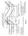
- FIG. 5is a graph in connection with issues when an access terminal operates in a strong busty interference environment.
- FIG. 6is a graph in connection with a power control approach for an access terminal operating in a strong interference environment.
- the geographic areas served by access pointsmay vary in size, may include smaller service areas, and/or may be located within larger service areas. Larger geographic areas that include one or more smaller service areas are referred to as “macrocell areas,” and an access point that serves a macrocell area is referred to as a “macrocell.” Macrocells can comprise one or several sectors by using multiple antennas.
- one or more access pointsmay be located to serve smaller geographic areas, referred to as “femtocell areas.”
- An access point that serves a femtocell areais referred to as a “femtocell access point.”
- a macrocellfor example, may provide coverage to an area of a few blocks, while a femtocell access point may provide coverage to an area spanning a floor of a building, a house, or an office space.
- a private access pointmay include, for example, a femtocell access point or a picocell access point.
- a private access pointmay be installed anywhere, for example, a home, an office, a public space, or a restaurant.
- private access pointswill be described hereinafter as femtocell access points or FAPs.
- a radio access network (RAN) 100includes multiple macro access points or “macrocells” 108 , 110 , and 112 located in macrocell areas 102 , 104 , and 106 , respectively.
- the macrocell areas 102 , 104 , and 106can include one or more femtocell access points (FAPs).
- FAPsfemtocell access points
- the macrocells 108 , 110 , and 112are each configured to communicate with an access terminal over an airlink.
- macrocell 108communicates with access terminal (AT) 116 over an airlink 109 .
- ATaccess terminal
- Macrocells 108 , 110 , and 112are connected over a backhaul connection (e.g., backhaul connection 118 a or 118 b ) to a radio network controller (RNC) which in turn communicates with the service provider's core network 122 , e.g., via RNC 120 a or 120 b , which may be one or more physical devices at different locations.
- RNCradio network controller
- the RAN 100is configured to support various mobile wireless access technologies, examples of which include Universal Mobile Telecommunications System (UMTS) and Code Division Multiple Access (CDMA) 2000.
- UMTSUniversal Mobile Telecommunications System
- CDMACode Division Multiple Access
- the 1xEV-DO protocolhas been standardized by the Telecommunication Industry Association (TIA) as TIA/EIA/IS-856, “CDMA2000 High Rate Packet Data Air Interface Specification,” 3GPP2 C.S0024-0, Version 4.0, Oct. 25, 2002, which is incorporated herein by reference.
- Revision A to this specificationhas been published as TIA/EIA/IS-856A, “CDMA2000 High Rate Packet Data Air Interface Specification,” 3GPP2 C.S0024-A, Version 2.0, July 2005. Revision A is also incorporated herein by reference.
- a radio network access point 202may be deployed in a user's home 200 in a similar manner as a WiFi® access point.
- a radio network access pointis referred to as a private access point.
- the private access point 202may use an available high-speed internet connection, such as a DSL or cable modem 204 , as the backhaul, with the RNC functionality implemented in the private access point 202 .
- Such a private access pointmay be installed anywhere, for example, in an office, a public space, or a restaurant. When this description refers to a private access point being in a “home,” that encompasses any such location.
- Private access pointsmay include, for example, femtocells or picocells.
- a private access pointmay be integrated into a cable modem or other network hardware, such as a router or WiFi access point.
- a neighboring home 210may have its own private access point 212 connected to its cable modem 214 for use by its owner's authorized access terminal 216 .
- Neighboring private access pointsmay operate independently, in part because real-time communication is difficult between neighboring private access points. Private access points may also operate in a licensed spectrum.
- AT 116 and 216are referred to as femto ATs that are served by 202 and 212 , respectively. There is no communication between the macro RNC 120 and the femto ATs 116 and 216 .
- a reverse link power control schemeincludes open loop power control (also referred to “autonomous power control”) and closed loop power control.
- Open loop power controlis used when a call is initiated. That is, ATs in idle mode autonomously set their power levels based on received signal strength from a BTS.
- Closed loop power controlincludes inner loop power control (ILPC) and outer loop power control (OLPC), both of which are usually performed by the access network.
- ILPCinner loop power control
- OLPCouter loop power control
- the outer loopmay evaluate the current frame error rate and adjust a target signal-to-interference-plus-noise ratio (SINR) threshold accordingly, based on the pilot signal from the AT.
- SINRtarget signal-to-interference-plus-noise ratio
- the normal SINR valueusually lies in a fairly narrow range of a few dBs.
- the BTSmay compare the received signal level of each AT with the outer loop threshold in order to track the desired SINR and issue “Power Up” or “Power Down” command to the AT.
- soft handovercan achieve smoother transmission and less ping-pong effects (i.e., the phenomenon that, when a mobile moves in and out of cell's boundary, frequent hard handover occurs).
- macro systemit has been shown that the individual link quality can be improved by soft handover.
- macro ATscan be served simultaneously by several BTSs and all serving BTSs issue “Power Up” and “Power Down” commands. When the commands differ, the ATs obey the Power Down command so as to minimize reverse link power.
- a radio nodesuch as base station 108 in FIGS. 1 and 2
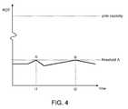
- the amount of data traffic supported by a radio node in a sectoris referred to as the pole capacity.
- pole capacityis a theoretical maximum that is limited by radio frequency (RF) interference present in the sector, which may be caused by multiple ATs transmitting in the sector, ATs from adjacent sectors, and ATs from other networks.
- RFradio frequency
- ROTRadio over-thermal
- a radio access networkcan monitor the rise in thermal noise (ROT) at the radio receiver for each sector. If the ROT reaches some threshold value indicating that the sector is becoming overloaded, the radio access network will command the access terminals in the sector to reduce or freeze transmission power and/or transmission data rate. As the ROT falls below the threshold value, the network may authorize the ATs to increase power and/or transmission rate.
- ROTthermal noise
- a radio access networkmonitors ROT of a RN's radio receiver for a particular sector. If the ROT reaches a certain threshold A below the pole capacity of the sector (e.g., such as when the ROT reaches points A and B at times t 1 and t 2 respectively), the radio access network commands ATs within the sector to reduce or freeze their transmission power and/or transmission data rate. As the ROT falls below the threshold, the radio may permit ATs to increase their transmission power or rate. While a single threshold is illustrated in FIG. 4 , in some implementations, a radio access network may be configured to have multiple thresholds which each trigger an increasingly stringent power control algorithm.
- a wireless communication systemcan control transmission rate of ATs in a sector by setting (or clearing) the reverse activity bit (RAB) in the reverse activity channel on the forward link.
- RABreverse activity bit
- the radio node for the affected sectorsets the RAB. If the ROT value is below the threshold, the RAB is cleared.
- the ATWhen an AT receives data on a multi-access communication channel with the RAB set, the AT becomes aware that the sector is over-loaded and executes an algorithm to determine whether to freeze or reduce its transmit rate. If the algorithm has a first outcome, the AT freezes its transmit rate.
- the ATdecreases its rate from its current rate to the next lowest rate defined by the 1xEV-DO standard. By reducing the rate at which ATs transmit on the reverse link, ATs transmit at less power and cause less interference in the sector, which decreases the ATs usage of the sector's capacity.
- an ATWhen an AT is in soft handover, it receives RABs from all its serving BTSs and uses a restrictive setting.
- the Universal Mobile Telecommunication Systemis a third generation (3G) mobile communications system that provides a range of broadband services to wireless and mobile communications.
- the power of the reverse link pilot channelis controlled by OLPC and ILPC loops, following the same principles as in CDMA.
- the UMTSuses a base station (BS)-driven (i.e., scheduled) approach in its uplink. That is, a UMTS BS may use an Access Grant Channel (AGCH) and/or Relative Grant Channel (RGCH) to allocate power for reverse link data transmission to one or more simultaneous operative ATs.
- BSbase station
- BSbase station
- BSbase station
- a UMTS BSmay use an Access Grant Channel (AGCH) and/or Relative Grant Channel (RGCH) to allocate power for reverse link data transmission to one or more simultaneous operative ATs.
- AGCHAccess Grant Channel
- RGCHRelative Grant Channel
- the schedulerinsures that the power level of ROT (measured in dB) does not exceed
- various geographically dispersed FAPscan be transmitting signals at substantially the same time. These signals are received and combined at each individual AT in different sectors or cells. It is useful for each AT to determine received power on a per sector basis so that the AT can set a transmit power at a level that is not too high, thereby causing excessive interference, and not too low which might result in the FAP not receiving a signal from the AT.
- the primary sources of interference with a particular AT's transmissionsare other ATs in the same sector (i.e., in sector interference or intra-cell interference) or different sectors (i.e., out-of-sector interference or inter-cell interference).
- an AT's tolerance on inter-cell interferencecan impact the SINR thereby requiring proper power control.
- thisis done by using soft handover, which allows a base station to control ATs in neighboring sectors.
- soft handoveris not used with femtocells and strong uncontrolled interference can originate from nearby ATs served by macro cells or by nearby FAPs.
- bursty uplink interferencei.e., primarily out-of-sector inference (I oc ) may be present in transmissions from a macro AT connected to a macro cell, while impacting nearby femtocells and links to femto attached ATs.
- the RAB thresholdmay be triggered to force a particular AT exposed to strong interference to, e.g., its minimum data rate. This is especially true when a macro AT is nearby, i.e., a femto AT's performance can be greatly impacted.
- macro AT interferencemay be uncontrollable if there is no cooperation (e.g., soft handoff) between the femto ATs and macro ATs.
- Such interferencecan also vary in a wide range, and can be as high as 40 dB above the thermal noise level under some conditions.
- a macro ATmay generate strong bursty interference.
- a femto ATmay accordingly experience a rapid and dramatic power change of the out-of-sector interference I oc at the beginning of every burst (see, e.g., 502 a , 502 b ), causing the SINR to be reduced.
- the femto ATmay suffer lost frames due to insufficient SINR and call quality degradation.
- a FAPmay use the ILPC to try to maintain the SINR at a target level by issuing “Power Up” commands. This results in a gradual adjustment 504 to the AT transmission power level of, e.g., true pilot power and traffic power.
- This adjustment processis usually a function of time.
- the base stationmay also use the OLPC to raise the target SINR.
- vI oc ⁇ ( k )max ⁇ [ ( 1 - 1 ⁇ ) ⁇ vI oc ⁇ ( k - 1 ) + 1 ⁇ ⁇ I oc ⁇ ( k ) , I oc ⁇ ( k ) ] Eq . ⁇ ( 2 ) where k denotes the time of the update.
- vPilotSINRvirtual pilot SINR
- ILPCinner loop power control
- vPilotSINR ⁇ ( i )pilotRxPower ⁇ ( i ) vI oc + InSectorLoad - SelfLoad ⁇ ( i ) Eq . ⁇ ( 3 )
- InSectorLoadis the obtained by measuring the sum of received power of all ATs serviced by the femto, and
- ExcessPower ⁇ ( i )ExcessPilotPower ⁇ ( i ) + ExcessTrafficPower ⁇ ( i ) , Eq . ⁇ ( 5 )
- ExcessPilotPower ⁇ ( i )max ( 0 , ( PilotPower ⁇ ( i ) - PilotPower ⁇ ( i ) ⁇ TargetPilotSINR PilotSINR ⁇ ( i ) ) ) , Eq .
- ExcessTrafficPower ⁇ ( i )ExcessPilotPower ⁇ ( i ) ⁇ TrafficToPilotRatio ⁇ ( PacketSize ⁇ ( i ) ) , Eq . ⁇ ( 7 )
- the TargetPilotSINR term in Eq. (6)is the typical SINR at which the pilot channel of an AT may be operating when the AT is operating above its minimum power
- the PilotSINR(i)is the SINR at which the pilot is currently being received.
- PilotPower ⁇ ( i ) ⁇ TargetPilotSINR PilotSINR ⁇ ( i ) ⁇ ⁇ in ⁇ ⁇ Eq . ⁇ ( 6 )would be the typical pilot received power at the base station if the AT i was operating above its minimum power level. The difference between the PilotPower(i) and
- PilotPower ⁇ ( i ) ⁇ TargetPilotSINR PilotSINR ⁇ ( i )yields the ExcessPilotPower(i).
- the Max operation in Eq. (6)may restrict the ExcessPilotPower from being a negative number.
- the ExcessTrafficPoweris also known based on Eq. (7) because the pilot and traffic power bear a deterministic relation at any given data packet size. As a result, the SINR per bit is practically maintained at a level appropriate to ensure a satisfactory throughput of the AT. A high throughput of the system may correspondingly result in a greater packet size or fewer transmissions.
- the granted power from a base station to an ATmay take into account the interference potentially caused by the femto AT to neighboring macros and femtos, and make sure the interference is not excessive.
- the received signal poweris a function of the separation between transmit and receive antennas.
- the received power at the base stationexpressed in terms of transmitted power is attenuated by a factor referred to as pathloss.
- an uplink data rate and power control schemecan estimate the path loss between the femto AT and the femtocells/macrocells using measurement reports from the femto AT.
- the power level of each femto AT powercan be obtained either directly from measurement reports or indirectly by measuring the Dedicated Physical Control Channel (DPCCH) power at the FAP and the path loss between the FAP and the femto AT. Subsequently, the power control scheme can make sure the granted power and path loss does not exceed a predetermined threshold.
- DPCCHDedicated Physical Control Channel
- I ocmay be defined as the sum of the equivalent noise and the received power from UEs connected to the macro Node-Bs (i.e., base stations in UMTS) and other Home Node-Bs (HNBs) (i.e., a 3GPP's term for 3G femtocells), computed over one transmission time interval (TTI).
- HNBsHome Node-Bs
- TTItransmission time interval
- HNBsmay compute a virtual pilot SINR as given in Eq. (3) and use this value for inner loop power control.
- other suitable filtering functionsmay not be precluded.
- the approach presented for excessive power computation in the case of an AT operating with reduced powermay still be applicable to HSUPA. Rather than computing the RAB threshold in EV-DO, that approach can be modified to compute granted power. Specifically, in assigning power grants to multiple ATs, the HNB may need to recognize if some of them are transmitting at their minimum power and hence will be transmitting at a much higher SINR than necessary. The HNB may need to take into account the excess power when computing grants for the remaining ATs.
- the techniques described aboveemploy the 1xRTT, EV-DO, UMTS, and HSDPA air interface standards, the techniques are also applicable to other air interface technologies in which access terminals determine which access points to communicate with.
- the techniques described hereincan be implemented in digital electronic circuitry, or in computer hardware, firmware, software, or in combinations of them.
- the techniquescan be implemented as a computer program product, i.e., a computer program tangibly embodied in an information carrier, e.g., in a machine-readable storage device or in a propagated signal, for execution by, or to control the operation of, data processing apparatus, e.g., a programmable processor, a computer, or multiple computers.
- a computer programcan be written in any form of programming language, including compiled or interpreted languages, and it can be deployed in any form, including as a stand-alone program or as a module, component, subroutine, or other unit suitable for use in a computing environment.
- a computer programcan be deployed to be executed on one computer or on multiple computers at one site or distributed across multiple sites and interconnected by a communication network.
- Method steps of the techniques described hereincan be performed by one or more programmable processors executing a computer program to perform functions of the invention by operating on input data and generating output. Method steps can also be performed by, and apparatus of the invention can be implemented as, special purpose logic circuitry, e.g., an FPGA (field programmable gate array) or an ASIC (application-specific integrated circuit). Modules can refer to portions of the computer program and/or the processor/special circuitry that implements that functionality.
- FPGAfield programmable gate array
- ASICapplication-specific integrated circuit
- processors suitable for the execution of a computer programinclude, by way of example, both general and special purpose microprocessors, and any one or more processors of any kind of digital computer.
- a processorwill receive instructions and data from a read-only memory or a random access memory or both.
- the essential elements of a computerare a processor for executing instructions and one or more memory devices for storing instructions and data.
- a computerwill also include, or be operatively coupled to receive data from or transfer data to, or both, one or more mass storage devices for storing data, e.g., magnetic, magneto-optical disks, or optical disks.
- Information carriers suitable for embodying computer program instructions and datainclude all forms of non-volatile memory, including by way of example semiconductor memory devices, e.g., EPROM, EEPROM, and flash memory devices; magnetic disks, e.g., internal hard disks or removable disks; magneto-optical disks; and CD-ROM and DVD-ROM disks.
- semiconductor memory devicese.g., EPROM, EEPROM, and flash memory devices
- magnetic diskse.g., internal hard disks or removable disks
- magneto-optical diskse.g., CD-ROM and DVD-ROM disks.
- the processor and the memorycan be supplemented by, or incorporated in special purpose logic circuitry.
- the techniques described hereincan be implemented on a computer having a display device, e.g., a CRT (cathode ray tube) or LCD (liquid crystal display) monitor, for displaying information to the user and a keyboard and a pointing device, e.g., a mouse or a trackball, by which the user can provide input to the computer (e.g., interact with a user interface element, for example, by clicking a button on such a pointing device).
- a display devicee.g., a CRT (cathode ray tube) or LCD (liquid crystal display) monitor
- a keyboard and a pointing devicee.g., a mouse or a trackball
- feedback provided to the usercan be any form of sensory feedback, e.g., visual feedback, auditory feedback, or tactile feedback; and input from the user can be received in any form, including acoustic, speech, or tactile input.
- the techniques described hereincan be implemented in a distributed computing system that includes a back-end component, e.g., as a data server, and/or a middleware component, e.g., an application server, and/or a front-end component, e.g., a client computer having a graphical user interface and/or a Web browser through which a user can interact with an implementation of the invention, or any combination of such back-end, middleware, or front-end components.
- the components of the systemcan be interconnected by any form or medium of digital data communication, e.g., a communication network. Examples of communication networks include a local area network (“LAN”) and a wide area network (“WAN”), e.g., the Internet, and include both wired and wireless networks.
- LANlocal area network
- WANwide area network
- the computing systemcan include clients and servers.
- a client and serverare generally remote from each other and typically interact over a communication network.
- the relationship of client and serverarises by virtue of computer programs running on the respective computers and having a client-server relationship to each other.
Landscapes
- Engineering & Computer Science (AREA)
- Computer Networks & Wireless Communication (AREA)
- Signal Processing (AREA)
- Quality & Reliability (AREA)
- Mobile Radio Communication Systems (AREA)
Abstract
Description
- 3GPP Technical Specification 25.331 version 8.3.0 Release 8, 2008-07, Universal Mobile Telecommunications System (UMTS); Radio Resource Control (RRC); Protocol specification;
- 3GPP Technical Specification 25.304 version 7.6.0 Release 7, 2008-07, Universal Mobile Telecommunications System (UMTS); User Equipment (UE) procedures in idle mode and procedures for cell reselection in connected mode;
- 3GPP Technical Specification 25.133 version 8.3.0 Release 8, 2008-06, Universal Mobile Telecommunications System (UMTS); Requirements for support of radio resource management (FDD);
- 3GPP Technical Specification 24.008 version 7.9.0 Release 7, 2007-10, Digital cellular telecommunications system (Phase 2+); Universal Mobile Telecommunications System (UMTS); Mobile radio interface Layer 3 specification; Core network protocols; Stage 3; and
- 3GPP Technical Specification 23.122 version 7.9.0 Release 7, 2007-06, Digital cellular telecommunications system (Phase 2+); Universal Mobile Telecommunications System (UMTS); Non-Access-Stratus (NAS) functions related to Mobile Station (MS) in idle mode.
ROT(t)=S(t)/N(t)
where, S(t) is the total signal power received at time ‘t’ at the radio node from all ATs in the sector (i.e., traffic power), and N(t) is the baseline noise power of the radio node's receiver at time ‘t’.
Ioc=RSSI−InSectorLoad Eq. (1)
where InSectorLoad is the sum of received powers of all ATs serviced by a FAP.
where k denotes the time of the update.
where InSectorLoad is the obtained by measuring the sum of received power of all ATs serviced by the femto, and
- SelfLoad=received power from the particular AT i.
RABThreshold=(vIoc+ΣiExcessPower(i))×RoTThresholdstatic Eq. (4)
where RoTThresholdstaticis a predetermined ROT threshold value (e.g., a linear value equivalent to 5-10 dB), and the term ΣiExcessPower(i) is obtained by summing over all ATs serviced by the FAP.
Here, the TargetPilotSINR term in Eq. (6) is the typical SINR at which the pilot channel of an AT may be operating when the AT is operating above its minimum power, and the PilotSINR(i) is the SINR at which the pilot is currently being received. Hence the term
would be the typical pilot received power at the base station if the AT i was operating above its minimum power level. The difference between the PilotPower(i) and
yields the ExcessPilotPower(i). The Max operation in Eq. (6) may restrict the ExcessPilotPower from being a negative number. Once the ExcessPilotPower for each AT is determined, the ExcessTrafficPower is also known based on Eq. (7) because the pilot and traffic power bear a deterministic relation at any given data packet size. As a result, the SINR per bit is practically maintained at a level appropriate to ensure a satisfactory throughput of the AT. A high throughput of the system may correspondingly result in a greater packet size or fewer transmissions.
Claims (18)
Priority Applications (1)
| Application Number | Priority Date | Filing Date | Title |
|---|---|---|---|
| US12/350,156US8160631B2 (en) | 2008-12-30 | 2009-01-07 | Power control for reverse link |
Applications Claiming Priority (2)
| Application Number | Priority Date | Filing Date | Title |
|---|---|---|---|
| US12/346,272US20100167777A1 (en) | 2008-12-30 | 2008-12-30 | Power control for reverse link |
| US12/350,156US8160631B2 (en) | 2008-12-30 | 2009-01-07 | Power control for reverse link |
Related Parent Applications (1)
| Application Number | Title | Priority Date | Filing Date |
|---|---|---|---|
| US12/346,272Continuation-In-PartUS20100167777A1 (en) | 2008-12-30 | 2008-12-30 | Power control for reverse link |
Publications (2)
| Publication Number | Publication Date |
|---|---|
| US20100167778A1 US20100167778A1 (en) | 2010-07-01 |
| US8160631B2true US8160631B2 (en) | 2012-04-17 |
Family
ID=42285606
Family Applications (1)
| Application Number | Title | Priority Date | Filing Date |
|---|---|---|---|
| US12/350,156Expired - Fee RelatedUS8160631B2 (en) | 2008-12-30 | 2009-01-07 | Power control for reverse link |
Country Status (1)
| Country | Link |
|---|---|
| US (1) | US8160631B2 (en) |
Cited By (23)
| Publication number | Priority date | Publication date | Assignee | Title |
|---|---|---|---|---|
| US20100303030A1 (en)* | 2007-11-26 | 2010-12-02 | Andreas Andersson | Dpcch and hs-dpcch control at low grants for e-dch |
| US20110003611A1 (en)* | 2009-07-01 | 2011-01-06 | Ntt Docomo, Inc. | Mobile and base station transceiver apparatus for communicating |
| US20110003559A1 (en)* | 2008-03-31 | 2011-01-06 | Motoki Morita | Radio station apparatus, radio resource control method, recording medium storing radio station control program, and radio communication system |
| US20110021197A1 (en)* | 2009-07-24 | 2011-01-27 | Qualcomm Incorporated | Apparatus and method for facilitating transfer to a secondary cell |
| US20120127954A1 (en)* | 2009-06-30 | 2012-05-24 | Lg Electronics Inc. | Femto base station and method for allocating radio resource thereof |
| US8886249B2 (en) | 2004-07-30 | 2014-11-11 | Airvana Lp | Method and system of setting transmitter power levels |
| US9237492B2 (en) | 2012-05-31 | 2016-01-12 | Commscope Technologies Llc | Providing circuit switched service |
| US9380466B2 (en) | 2013-02-07 | 2016-06-28 | Commscope Technologies Llc | Radio access networks |
| US20160197686A1 (en)* | 2015-01-06 | 2016-07-07 | Hughes Network Systems, Llc | Systems and methods for satellite noise and interference calibration using terminal measurements |
| US9414399B2 (en) | 2013-02-07 | 2016-08-09 | Commscope Technologies Llc | Radio access networks |
| TWI565225B (en)* | 2015-07-09 | 2017-01-01 | 國立中山大學 | Demodulation technique with power tracking |
| US9596322B2 (en) | 2014-06-11 | 2017-03-14 | Commscope Technologies Llc | Bitrate efficient transport through distributed antenna systems |
| US9936470B2 (en) | 2013-02-07 | 2018-04-03 | Commscope Technologies Llc | Radio access networks |
| US10057916B2 (en) | 2014-06-09 | 2018-08-21 | Commscope Technologies Llc | Radio access networks in which mobile devices in the same communication cell can be scheduled to use the same airlink resource |
| US10244507B2 (en) | 2013-09-24 | 2019-03-26 | Andrew Wireless Systems Gmbh | Distributed processing in a centralized radio access network |
| US10785791B1 (en) | 2015-12-07 | 2020-09-22 | Commscope Technologies Llc | Controlling data transmission in radio access networks |
| US10798667B2 (en) | 2018-06-08 | 2020-10-06 | Commscope Technologies Llc | Automatic transmit power control for radio points of a centralized radio access network that primarily provide wireless service to users located in an event area of a venue |
| US11219083B2 (en) | 2017-12-15 | 2022-01-04 | Google Llc | Establishing and terminating wireless links |
| US11304213B2 (en) | 2018-05-16 | 2022-04-12 | Commscope Technologies Llc | Dynamic uplink reuse in a C-RAN |
| US11395259B2 (en) | 2018-05-16 | 2022-07-19 | Commscope Technologies Llc | Downlink multicast for efficient front-haul utilization in a C-RAN |
| US11627497B2 (en) | 2018-09-04 | 2023-04-11 | Commscope Technologies Llc | Front-haul rate reduction for use in a centralized radio access network |
| US11678358B2 (en) | 2017-10-03 | 2023-06-13 | Commscope Technologies Llc | Dynamic downlink reuse in a C-RAN |
| US12219510B2 (en) | 2018-08-29 | 2025-02-04 | Commscope Technologies Llc | Clock synchronization in a centralized radio access network having multiple controllers |
Families Citing this family (27)
| Publication number | Priority date | Publication date | Assignee | Title |
|---|---|---|---|---|
| US6807405B1 (en) | 1999-04-28 | 2004-10-19 | Isco International, Inc. | Method and a device for maintaining the performance quality of a code-division multiple access system in the presence of narrow band interference |
| US8195187B2 (en) | 2001-06-25 | 2012-06-05 | Airvana Network Solutions, Inc. | Radio network control |
| US7603127B2 (en)* | 2001-10-12 | 2009-10-13 | Airvana, Inc. | Boosting a signal-to-interference ratio of a mobile station |
| US7926098B2 (en) | 2006-12-29 | 2011-04-12 | Airvana, Corp. | Handoff of a secure connection among gateways |
| US20100195553A1 (en) | 2008-03-18 | 2010-08-05 | Myers Theodore J | Controlling power in a spread spectrum system |
| US8958460B2 (en) | 2008-03-18 | 2015-02-17 | On-Ramp Wireless, Inc. | Forward error correction media access control system |
| US8520721B2 (en) | 2008-03-18 | 2013-08-27 | On-Ramp Wireless, Inc. | RSSI measurement mechanism in the presence of pulsed jammers |
| US8477830B2 (en) | 2008-03-18 | 2013-07-02 | On-Ramp Wireless, Inc. | Light monitoring system using a random phase multiple access system |
| US8385483B2 (en) | 2008-11-11 | 2013-02-26 | Isco International, Llc | Self-adaptive digital RF bandpass and bandstop filter architecture |
| US8160631B2 (en) | 2008-12-30 | 2012-04-17 | Airvana, Corp. | Power control for reverse link |
| EP2377345B1 (en)* | 2009-01-14 | 2015-09-16 | Nec Corporation | Method for interference mitigation for femtocell base stations of a wimax network |
| US8548455B2 (en)* | 2009-01-16 | 2013-10-01 | Broadcom Corporation | Method and system for installation and configuration of a femtocell |
| US8363699B2 (en) | 2009-03-20 | 2013-01-29 | On-Ramp Wireless, Inc. | Random timing offset determination |
| US20110030635A1 (en)* | 2009-08-04 | 2011-02-10 | International Engine Intellectual Property Company, Llc | Fuel injector nozzle for reduced coking |
| KR20110091093A (en)* | 2010-02-05 | 2011-08-11 | 삼성전자주식회사 | Uplink interference control method and apparatus in wireless mobile communication system |
| US8676216B2 (en)* | 2010-06-29 | 2014-03-18 | Qualcomm Incorporated | Method and apparatus for mitigating interference in femtocell deployments |
| US9008714B2 (en)* | 2010-12-23 | 2015-04-14 | Qualcomm Incorporated | Method and apparatus for dynamically adjusting a rise-over-thermal or noise rise threshold |
| US9319916B2 (en) | 2013-03-15 | 2016-04-19 | Isco International, Llc | Method and appartus for signal interference processing |
| US9148805B2 (en)* | 2013-05-10 | 2015-09-29 | Broadcom Corporation | Small cell base station DTX mode |
| US9794888B2 (en) | 2014-05-05 | 2017-10-17 | Isco International, Llc | Method and apparatus for increasing performance of a communication link of a communication node |
| EP3651386B1 (en) | 2015-05-04 | 2023-08-23 | ISCO International, LLC | Method and apparatus for increasing the performance of communication paths for communication nodes |
| WO2017210056A1 (en) | 2016-06-01 | 2017-12-07 | Isco International, Llc | Method and apparatus for performing signal conditioning to mitigate interference detected in a communication system |
| US10298279B2 (en) | 2017-04-05 | 2019-05-21 | Isco International, Llc | Method and apparatus for increasing performance of communication paths for communication nodes |
| US10812121B2 (en) | 2017-08-09 | 2020-10-20 | Isco International, Llc | Method and apparatus for detecting and analyzing passive intermodulation interference in a communication system |
| US10284313B2 (en) | 2017-08-09 | 2019-05-07 | Isco International, Llc | Method and apparatus for monitoring, detecting, testing, diagnosing and/or mitigating interference in a communication system |
| EP3682564A4 (en)* | 2017-09-11 | 2021-04-21 | INTEL Corporation | INTERFERENCE MITIGATION SCHEMES FOR FULL-DUPLEX CELLULAR SYSTEMS |
| KR102414927B1 (en)* | 2018-03-21 | 2022-06-30 | 삼성전자 주식회사 | Method and apparatus for authenticating a device using wireless local area network service |
Citations (58)
| Publication number | Priority date | Publication date | Assignee | Title |
|---|---|---|---|---|
| US5369789A (en)* | 1991-01-10 | 1994-11-29 | Matsushita Electric Industrial Co. Ltd. | Burst signal transmitter |
| US20020196749A1 (en) | 2001-06-25 | 2002-12-26 | Eyuboglu M. Vedat | Radio network control |
| US20030100311A1 (en) | 2001-10-12 | 2003-05-29 | Sae-Young Chung | Boosting a signal-to-interference ratio of a mobile station |
| US6711144B1 (en) | 2000-09-15 | 2004-03-23 | Airvana, Inc. | Multi-user communication of voice and data |
| US6731618B1 (en) | 2000-10-20 | 2004-05-04 | Airvana, Inc. | Coding for multi-user communication |
| US6741862B2 (en) | 2001-02-07 | 2004-05-25 | Airvana, Inc. | Enhanced reverse-link rate control in wireless communication |
| US6781999B2 (en) | 2001-07-23 | 2004-08-24 | Airvana, Inc. | Broadcasting and multicasting in wireless communication |
| US20050213555A1 (en) | 2001-06-25 | 2005-09-29 | Vedat Eyuboglu | Radio network control |
| US20050243749A1 (en) | 2004-04-28 | 2005-11-03 | Sepehr Mehrabanzad | Reverse link power control |
| US20050245279A1 (en) | 2004-04-28 | 2005-11-03 | Sepehr Mehrabanzad | Reverse link power control |
| US20060067422A1 (en) | 2004-09-30 | 2006-03-30 | Sae-Young Chung | Modulation for broadcasting from multiple transmitters |
| US20060067451A1 (en) | 2004-09-30 | 2006-03-30 | Pollman Michael D | Providing global positioning system timing signals to remote cellular base stations |
| US20060079196A1 (en)* | 2004-10-08 | 2006-04-13 | Oki Electric Industry Co., Ltd. | Data receiver adaptive to RSSI and a method of determining its threshold |
| US20060084460A1 (en)* | 2004-10-20 | 2006-04-20 | Toshiba America Research Inc. (Tari) | Terminal transmit power control with link adaptation |
| US20060126509A1 (en) | 2004-12-09 | 2006-06-15 | Firas Abi-Nassif | Traffic management in a wireless data network |
| US20060159045A1 (en) | 2005-01-18 | 2006-07-20 | Satish Ananthaiyer | Reverse link rate and stability control |
| US20060240782A1 (en) | 2005-04-26 | 2006-10-26 | Pollman Michael D | Measuring interference in radio networks |
| US20060246939A1 (en)* | 2005-04-27 | 2006-11-02 | Alcatel | Transmission power control for HSDPA connections |
| US20060294241A1 (en) | 2005-06-24 | 2006-12-28 | Sanjay Cherian | Preserving sessions in a wireless network |
| US20060291420A1 (en) | 2005-06-27 | 2006-12-28 | Dennis Ng | Network-initiated dormant handoffs |
| US20070026884A1 (en) | 2005-07-28 | 2007-02-01 | Prashanth Rao | Controlling usage capacity in a radio access network |
| US20070058628A1 (en) | 2005-09-15 | 2007-03-15 | Palnati Prasasth R | Broadcasting in wireless systems |
| US7200391B2 (en) | 2002-12-06 | 2007-04-03 | Airvana, Inc. | Capacity enhancement schemes for forward and reverse links of distributed cellular base stations |
| US20070077948A1 (en) | 2005-10-04 | 2007-04-05 | Vivek Sharma | Non-circular paging areas |
| US20070115896A1 (en) | 2005-11-18 | 2007-05-24 | Philip To | Resource allocation in a radio access network |
| US20070140184A1 (en) | 2005-12-16 | 2007-06-21 | Deepak Garg | Radio frequency dragging prevention |
| US20070140172A1 (en) | 2005-12-16 | 2007-06-21 | Deepak Garg | Radio network control |
| US20070140218A1 (en) | 2005-12-16 | 2007-06-21 | Nair Girish R | Managing backhaul connections in radio access networks |
| US20070140185A1 (en) | 2005-12-16 | 2007-06-21 | Deepak Garg | Radio network communication |
| US20070155329A1 (en) | 2005-12-29 | 2007-07-05 | Sepehr Mehrabanzad | Detection of radio frequency interference in wireless communication systems |
| US20070207811A1 (en)* | 2004-09-13 | 2007-09-06 | Suman Das | A method for controlling paging and registration of a mobile device in a wireless communications system |
| US20070220573A1 (en) | 2006-03-20 | 2007-09-20 | Chiussi Fabio M | Unicasting and multicasting multimedia services |
| US7277446B1 (en) | 2000-11-02 | 2007-10-02 | Airvana, Inc. | Communication of digital data over a wireless transmission medium |
| US20070230419A1 (en) | 2006-03-31 | 2007-10-04 | Sundar Raman | QoS signaling to support fairness |
| US20070238442A1 (en) | 2006-03-31 | 2007-10-11 | Amit Mate | Signaling for push-to-talk |
| US20070238476A1 (en) | 2006-03-28 | 2007-10-11 | Vivek Sharma | Managing page cycle periods of access terminals |
| US20070242648A1 (en) | 2006-04-12 | 2007-10-18 | Deepak Garg | Managing dormant handoffs in radio access networks |
| US20070248042A1 (en) | 2006-04-19 | 2007-10-25 | Gopal Harikumar | Channel assignment in wireless communication |
| US7299278B2 (en) | 2002-01-16 | 2007-11-20 | Airvana, Inc. | Managing network faults |
| US20070280170A1 (en)* | 2005-02-18 | 2007-12-06 | Yoshihiro Kawasaki | Base station and interference reduction method in base station |
| US20080003988A1 (en) | 2004-07-30 | 2008-01-03 | Andrew Richardson | Local Network Node |
| US20080013488A1 (en) | 2006-07-14 | 2008-01-17 | Deepak Garg | Dynamic modification of route update protocols |
| US20080062925A1 (en) | 2006-09-07 | 2008-03-13 | Amit Mate | Controlling reverse link interference in private access points for wireless networking |
| US20080065752A1 (en) | 2006-09-07 | 2008-03-13 | Ch Ng Shi Baw | Provisioning private access points for wireless networking |
| US20080069020A1 (en) | 2004-07-30 | 2008-03-20 | Andrew Richardson | Signal Transmission Method from a Local Network Node |
| US20080069028A1 (en) | 2004-07-30 | 2008-03-20 | Andrew Richardson | Power Control in a Local Network Node (Lln) |
| US20080076398A1 (en) | 2006-09-07 | 2008-03-27 | Amit Mate | Configuring preferred user zone lists for private access points for wireless networking |
| US20080117842A1 (en) | 2006-11-20 | 2008-05-22 | Rao Roshan M | Multicast Flow Distribution |
| US20080119172A1 (en) | 2006-11-20 | 2008-05-22 | Rao Roshan M | Multicasting Push-To-Media Content |
| US20080120417A1 (en) | 2006-11-22 | 2008-05-22 | Gopal Harikumar | Network-Initiated Session Recovery |
| US20080139203A1 (en) | 2006-12-12 | 2008-06-12 | Dennis Ng | Access Terminal Session Authentication |
| US20080146232A1 (en) | 2006-12-19 | 2008-06-19 | Douglas Norman Knisely | Neighbor list provision in a communication network |
| US20080151843A1 (en) | 2006-12-20 | 2008-06-26 | Ravi Valmikam | Communication group configuration in a network |
| US20080162924A1 (en) | 2006-12-29 | 2008-07-03 | Airvana, Inc. | Handoff of a secure connection among gateways |
| US20080159236A1 (en) | 2006-12-28 | 2008-07-03 | Airvana, Inc. | Assigning code space to portable base stations |
| US20080162926A1 (en) | 2006-12-27 | 2008-07-03 | Jay Xiong | Authentication protocol |
| US20100167777A1 (en) | 2008-12-30 | 2010-07-01 | Airvana, Inc. | Power control for reverse link |
| US20100167778A1 (en) | 2008-12-30 | 2010-07-01 | Balaji Raghothaman | Power control for reverse link |
- 2009
- 2009-01-07USUS12/350,156patent/US8160631B2/ennot_activeExpired - Fee Related
Patent Citations (61)
| Publication number | Priority date | Publication date | Assignee | Title |
|---|---|---|---|---|
| US5369789A (en)* | 1991-01-10 | 1994-11-29 | Matsushita Electric Industrial Co. Ltd. | Burst signal transmitter |
| US6711144B1 (en) | 2000-09-15 | 2004-03-23 | Airvana, Inc. | Multi-user communication of voice and data |
| US6731618B1 (en) | 2000-10-20 | 2004-05-04 | Airvana, Inc. | Coding for multi-user communication |
| US7277446B1 (en) | 2000-11-02 | 2007-10-02 | Airvana, Inc. | Communication of digital data over a wireless transmission medium |
| US6741862B2 (en) | 2001-02-07 | 2004-05-25 | Airvana, Inc. | Enhanced reverse-link rate control in wireless communication |
| US20020196749A1 (en) | 2001-06-25 | 2002-12-26 | Eyuboglu M. Vedat | Radio network control |
| US20050213555A1 (en) | 2001-06-25 | 2005-09-29 | Vedat Eyuboglu | Radio network control |
| US7170871B2 (en) | 2001-06-25 | 2007-01-30 | Airvana, Inc. | Radio network control |
| US20070097916A1 (en) | 2001-06-25 | 2007-05-03 | Airvana, Inc., A Massachusetts Corporation | Radio network control |
| US6781999B2 (en) | 2001-07-23 | 2004-08-24 | Airvana, Inc. | Broadcasting and multicasting in wireless communication |
| US20030100311A1 (en) | 2001-10-12 | 2003-05-29 | Sae-Young Chung | Boosting a signal-to-interference ratio of a mobile station |
| US7242958B2 (en) | 2001-10-12 | 2007-07-10 | Airvana, Inc. | Boosting a signal-to-interference ratio of a mobile station |
| US7299278B2 (en) | 2002-01-16 | 2007-11-20 | Airvana, Inc. | Managing network faults |
| US7200391B2 (en) | 2002-12-06 | 2007-04-03 | Airvana, Inc. | Capacity enhancement schemes for forward and reverse links of distributed cellular base stations |
| US20050245279A1 (en) | 2004-04-28 | 2005-11-03 | Sepehr Mehrabanzad | Reverse link power control |
| US20050243749A1 (en) | 2004-04-28 | 2005-11-03 | Sepehr Mehrabanzad | Reverse link power control |
| US20080069028A1 (en) | 2004-07-30 | 2008-03-20 | Andrew Richardson | Power Control in a Local Network Node (Lln) |
| US20080069020A1 (en) | 2004-07-30 | 2008-03-20 | Andrew Richardson | Signal Transmission Method from a Local Network Node |
| US20080003988A1 (en) | 2004-07-30 | 2008-01-03 | Andrew Richardson | Local Network Node |
| US20070207811A1 (en)* | 2004-09-13 | 2007-09-06 | Suman Das | A method for controlling paging and registration of a mobile device in a wireless communications system |
| US20060067451A1 (en) | 2004-09-30 | 2006-03-30 | Pollman Michael D | Providing global positioning system timing signals to remote cellular base stations |
| US20060067422A1 (en) | 2004-09-30 | 2006-03-30 | Sae-Young Chung | Modulation for broadcasting from multiple transmitters |
| US20060079196A1 (en)* | 2004-10-08 | 2006-04-13 | Oki Electric Industry Co., Ltd. | Data receiver adaptive to RSSI and a method of determining its threshold |
| US20060084460A1 (en)* | 2004-10-20 | 2006-04-20 | Toshiba America Research Inc. (Tari) | Terminal transmit power control with link adaptation |
| US20060126509A1 (en) | 2004-12-09 | 2006-06-15 | Firas Abi-Nassif | Traffic management in a wireless data network |
| US20060159045A1 (en) | 2005-01-18 | 2006-07-20 | Satish Ananthaiyer | Reverse link rate and stability control |
| US20070280170A1 (en)* | 2005-02-18 | 2007-12-06 | Yoshihiro Kawasaki | Base station and interference reduction method in base station |
| US20060240782A1 (en) | 2005-04-26 | 2006-10-26 | Pollman Michael D | Measuring interference in radio networks |
| US20060246939A1 (en)* | 2005-04-27 | 2006-11-02 | Alcatel | Transmission power control for HSDPA connections |
| US20060294241A1 (en) | 2005-06-24 | 2006-12-28 | Sanjay Cherian | Preserving sessions in a wireless network |
| US20060291420A1 (en) | 2005-06-27 | 2006-12-28 | Dennis Ng | Network-initiated dormant handoffs |
| US20070026884A1 (en) | 2005-07-28 | 2007-02-01 | Prashanth Rao | Controlling usage capacity in a radio access network |
| US20070058628A1 (en) | 2005-09-15 | 2007-03-15 | Palnati Prasasth R | Broadcasting in wireless systems |
| US20070077948A1 (en) | 2005-10-04 | 2007-04-05 | Vivek Sharma | Non-circular paging areas |
| US20070115896A1 (en) | 2005-11-18 | 2007-05-24 | Philip To | Resource allocation in a radio access network |
| US20070140185A1 (en) | 2005-12-16 | 2007-06-21 | Deepak Garg | Radio network communication |
| US20070140218A1 (en) | 2005-12-16 | 2007-06-21 | Nair Girish R | Managing backhaul connections in radio access networks |
| US20070140184A1 (en) | 2005-12-16 | 2007-06-21 | Deepak Garg | Radio frequency dragging prevention |
| US20070140172A1 (en) | 2005-12-16 | 2007-06-21 | Deepak Garg | Radio network control |
| US20070155329A1 (en) | 2005-12-29 | 2007-07-05 | Sepehr Mehrabanzad | Detection of radio frequency interference in wireless communication systems |
| US20070220573A1 (en) | 2006-03-20 | 2007-09-20 | Chiussi Fabio M | Unicasting and multicasting multimedia services |
| US20070238476A1 (en) | 2006-03-28 | 2007-10-11 | Vivek Sharma | Managing page cycle periods of access terminals |
| US20070230419A1 (en) | 2006-03-31 | 2007-10-04 | Sundar Raman | QoS signaling to support fairness |
| US20070238442A1 (en) | 2006-03-31 | 2007-10-11 | Amit Mate | Signaling for push-to-talk |
| US20070242648A1 (en) | 2006-04-12 | 2007-10-18 | Deepak Garg | Managing dormant handoffs in radio access networks |
| US20070248042A1 (en) | 2006-04-19 | 2007-10-25 | Gopal Harikumar | Channel assignment in wireless communication |
| US20080013488A1 (en) | 2006-07-14 | 2008-01-17 | Deepak Garg | Dynamic modification of route update protocols |
| US20080062925A1 (en) | 2006-09-07 | 2008-03-13 | Amit Mate | Controlling reverse link interference in private access points for wireless networking |
| US20080065752A1 (en) | 2006-09-07 | 2008-03-13 | Ch Ng Shi Baw | Provisioning private access points for wireless networking |
| US20080076398A1 (en) | 2006-09-07 | 2008-03-27 | Amit Mate | Configuring preferred user zone lists for private access points for wireless networking |
| US20080117842A1 (en) | 2006-11-20 | 2008-05-22 | Rao Roshan M | Multicast Flow Distribution |
| US20080119172A1 (en) | 2006-11-20 | 2008-05-22 | Rao Roshan M | Multicasting Push-To-Media Content |
| US20080120417A1 (en) | 2006-11-22 | 2008-05-22 | Gopal Harikumar | Network-Initiated Session Recovery |
| US20080139203A1 (en) | 2006-12-12 | 2008-06-12 | Dennis Ng | Access Terminal Session Authentication |
| US20080146232A1 (en) | 2006-12-19 | 2008-06-19 | Douglas Norman Knisely | Neighbor list provision in a communication network |
| US20080151843A1 (en) | 2006-12-20 | 2008-06-26 | Ravi Valmikam | Communication group configuration in a network |
| US20080162926A1 (en) | 2006-12-27 | 2008-07-03 | Jay Xiong | Authentication protocol |
| US20080159236A1 (en) | 2006-12-28 | 2008-07-03 | Airvana, Inc. | Assigning code space to portable base stations |
| US20080162924A1 (en) | 2006-12-29 | 2008-07-03 | Airvana, Inc. | Handoff of a secure connection among gateways |
| US20100167777A1 (en) | 2008-12-30 | 2010-07-01 | Airvana, Inc. | Power control for reverse link |
| US20100167778A1 (en) | 2008-12-30 | 2010-07-01 | Balaji Raghothaman | Power control for reverse link |
Non-Patent Citations (6)
| Title |
|---|
| 3rd Generation Partnership Project "3GPP2", "cdma2000 High Rate Data Air Interface Specification", C.S0024-A, version 2.0, Jul. 2005 (1227 pages). |
| 3rd Generation Partnership Project "3GPP2", "cdma2000 High Rate Data Air Interface Specification", C.S0024-B, version 1.0, Apr. 2006 (1623 pages). |
| 3rd Generation Partnership Project "3GPP2", "cdma2000 High Rate Data Air Interface Specification", C.S0024-B, version 2.0, Mar. 2007 (1627 pages). |
| 3rd Generation Partnership Project "3GPP2", "cdma2000 High Rate Packet Data Air Interface Specification", C.S0024, version 4.0, Oct. 25, 2002 (548 pages). |
| 3rd Generation Partnership Project "3GPP2", "cdma2000 High Rate Packet Data Air Interface Specification", C.S0024-A, version 1.0, Mar. 2004 (1083 pages). |
| USPTO Non Final Office Action in U.S. Appl. No. 12/346,272, mailed Jul. 21, 2011 (25 pages). |
Cited By (54)
| Publication number | Priority date | Publication date | Assignee | Title |
|---|---|---|---|---|
| US8886249B2 (en) | 2004-07-30 | 2014-11-11 | Airvana Lp | Method and system of setting transmitter power levels |
| US20100303030A1 (en)* | 2007-11-26 | 2010-12-02 | Andreas Andersson | Dpcch and hs-dpcch control at low grants for e-dch |
| US8284728B2 (en)* | 2007-11-26 | 2012-10-09 | Telefonaktiebolaget Lm Ericsson (Publ) | DPCCH and HS-DPCCH control at low grants for E-DCH |
| US20110003559A1 (en)* | 2008-03-31 | 2011-01-06 | Motoki Morita | Radio station apparatus, radio resource control method, recording medium storing radio station control program, and radio communication system |
| US8554262B2 (en)* | 2008-03-31 | 2013-10-08 | Nec Corporation | Radio station apparatus, radio resource control method, recording medium storing radio station control program, and radio communication system |
| US20120127954A1 (en)* | 2009-06-30 | 2012-05-24 | Lg Electronics Inc. | Femto base station and method for allocating radio resource thereof |
| US8599784B2 (en)* | 2009-06-30 | 2013-12-03 | Lg Electronics Inc. | Femto base station and method for allocating radio resource thereof |
| US20110003611A1 (en)* | 2009-07-01 | 2011-01-06 | Ntt Docomo, Inc. | Mobile and base station transceiver apparatus for communicating |
| US8472886B2 (en)* | 2009-07-01 | 2013-06-25 | Ntt Docomo, Inc. | Mobile and base station transceiver apparatus for communicating |
| US20110021197A1 (en)* | 2009-07-24 | 2011-01-27 | Qualcomm Incorporated | Apparatus and method for facilitating transfer to a secondary cell |
| US9237492B2 (en) | 2012-05-31 | 2016-01-12 | Commscope Technologies Llc | Providing circuit switched service |
| US9936470B2 (en) | 2013-02-07 | 2018-04-03 | Commscope Technologies Llc | Radio access networks |
| US10764846B2 (en) | 2013-02-07 | 2020-09-01 | Commscope Technologies Llc | Radio access networks |
| US9414399B2 (en) | 2013-02-07 | 2016-08-09 | Commscope Technologies Llc | Radio access networks |
| US12418907B2 (en) | 2013-02-07 | 2025-09-16 | Outdoor Wireless Networks LLC | Radio access networks |
| US11700602B2 (en) | 2013-02-07 | 2023-07-11 | Commscope Technologies Llc | Radio access networks |
| US11706640B2 (en) | 2013-02-07 | 2023-07-18 | Commscope Technologies Llc | Radio access networks |
| US12170973B2 (en) | 2013-02-07 | 2024-12-17 | Commscope Technologies Llc | Radio access networks |
| US11445455B2 (en) | 2013-02-07 | 2022-09-13 | Commscope Technologies Llc | Radio access networks |
| US11729758B2 (en) | 2013-02-07 | 2023-08-15 | Commscope Technologies Llc | Radio access networks |
| US11122447B2 (en) | 2013-02-07 | 2021-09-14 | Commscope Technologies Llc | Radio access networks |
| US11102663B2 (en) | 2013-02-07 | 2021-08-24 | Commscope Technologies Llc | Radio access networks |
| US10064072B2 (en) | 2013-02-07 | 2018-08-28 | Commscope Technologies Llc | Radio access networks |
| US10142858B2 (en) | 2013-02-07 | 2018-11-27 | Commscope Technologies Llc | Radio access networks |
| US12047933B2 (en) | 2013-02-07 | 2024-07-23 | Commscope Technologies Llc | Radio access networks |
| US10292175B2 (en) | 2013-02-07 | 2019-05-14 | Commscope Technologies Llc | Radio access networks |
| US9380466B2 (en) | 2013-02-07 | 2016-06-28 | Commscope Technologies Llc | Radio access networks |
| US12156048B2 (en) | 2013-02-07 | 2024-11-26 | Commscope Technologies Llc | Radio access networks |
| US10455597B2 (en) | 2013-02-07 | 2019-10-22 | Commscope Technologies Llc | Radio access networks |
| US10244507B2 (en) | 2013-09-24 | 2019-03-26 | Andrew Wireless Systems Gmbh | Distributed processing in a centralized radio access network |
| US10536959B2 (en) | 2014-06-09 | 2020-01-14 | Commscope Technologies Llc | Radio access networks in which remote units are configured to perform at least some baseband processing |
| US11974269B2 (en) | 2014-06-09 | 2024-04-30 | Commscope Technologies Llc | Radio access networks |
| US11082997B2 (en) | 2014-06-09 | 2021-08-03 | Commscope Technologies Llc | Radio access networks in which mobile devices can be scheduled to use the same time-frequency resource |
| US10057916B2 (en) | 2014-06-09 | 2018-08-21 | Commscope Technologies Llc | Radio access networks in which mobile devices in the same communication cell can be scheduled to use the same airlink resource |
| US10333591B2 (en) | 2014-06-11 | 2019-06-25 | Commscope Technologies Llc | Bitrate efficient transport through distributed antenna systems |
| US10020851B2 (en) | 2014-06-11 | 2018-07-10 | Commscope Technologies Llc | Bitrate efficient transport through distributed antenna systems |
| US9954584B2 (en) | 2014-06-11 | 2018-04-24 | Commscope Technologies Llc | Bitrate efficient transport through distributed antenna systems |
| US9686379B2 (en) | 2014-06-11 | 2017-06-20 | Commscope Technologies Llc | Bitrate efficient transport through distributed antenna systems |
| US9596322B2 (en) | 2014-06-11 | 2017-03-14 | Commscope Technologies Llc | Bitrate efficient transport through distributed antenna systems |
| US20160197686A1 (en)* | 2015-01-06 | 2016-07-07 | Hughes Network Systems, Llc | Systems and methods for satellite noise and interference calibration using terminal measurements |
| US10361796B2 (en) | 2015-01-06 | 2019-07-23 | Hughes Network Systems, Llc | Systems and methods for satellite noise and interference calibration using terminal measurements |
| US9749067B2 (en)* | 2015-01-06 | 2017-08-29 | Hughes Network Systems, Llc | Systems and methods for satellite noise and interference calibration using terminal measurements |
| TWI565225B (en)* | 2015-07-09 | 2017-01-01 | 國立中山大學 | Demodulation technique with power tracking |
| US10785791B1 (en) | 2015-12-07 | 2020-09-22 | Commscope Technologies Llc | Controlling data transmission in radio access networks |
| US11678358B2 (en) | 2017-10-03 | 2023-06-13 | Commscope Technologies Llc | Dynamic downlink reuse in a C-RAN |
| US12426075B2 (en) | 2017-10-03 | 2025-09-23 | Outdoor Wireless Networks LLC | Dynamic downlink reuse in a C-RAN |
| US11690125B2 (en) | 2017-12-15 | 2023-06-27 | Google Llc | Establishing and terminating wireless links |
| US11219083B2 (en) | 2017-12-15 | 2022-01-04 | Google Llc | Establishing and terminating wireless links |
| US12052789B2 (en) | 2017-12-15 | 2024-07-30 | Google Llc | Establishing and terminating wireless links |
| US11395259B2 (en) | 2018-05-16 | 2022-07-19 | Commscope Technologies Llc | Downlink multicast for efficient front-haul utilization in a C-RAN |
| US11304213B2 (en) | 2018-05-16 | 2022-04-12 | Commscope Technologies Llc | Dynamic uplink reuse in a C-RAN |
| US10798667B2 (en) | 2018-06-08 | 2020-10-06 | Commscope Technologies Llc | Automatic transmit power control for radio points of a centralized radio access network that primarily provide wireless service to users located in an event area of a venue |
| US12219510B2 (en) | 2018-08-29 | 2025-02-04 | Commscope Technologies Llc | Clock synchronization in a centralized radio access network having multiple controllers |
| US11627497B2 (en) | 2018-09-04 | 2023-04-11 | Commscope Technologies Llc | Front-haul rate reduction for use in a centralized radio access network |
Also Published As
| Publication number | Publication date |
|---|---|
| US20100167778A1 (en) | 2010-07-01 |
Similar Documents
| Publication | Publication Date | Title |
|---|---|---|
| US8160631B2 (en) | Power control for reverse link | |
| US20100167777A1 (en) | Power control for reverse link | |
| US11564175B2 (en) | Method and apparatus for controlling uplink power in wireless communication system | |
| RU2471315C2 (en) | Tuning of transfer capacity based on channel quality | |
| EP2268072B1 (en) | Radio station device, radio resource control method, recording medium containing radio station control program | |
| US8385832B2 (en) | Inter-cell interference control in an uplink multi-carrier radio communications system | |
| EP2147506B1 (en) | Signal to interference ratio error as a load instability indicator for load control in cellular systems | |
| US8126403B2 (en) | Estimating and limiting inter-cell interference | |
| WO2013108315A1 (en) | Wireless communication system, transmission power control device, base station device, parameter supply device, and transmission power control method | |
| US20120142364A1 (en) | Interference-control method and femto base station | |
| US8989036B2 (en) | Uplink load prediction using kalman filters | |
| EP2564642B1 (en) | Methods for management of macro network key performance indicators impacts for a mass deployment of femtocells | |
| KR20190005614A (en) | Apparatus and method for load distribution of base station in wireless communication system | |
| US20130094374A1 (en) | Method and apparatus for virtual adaptive uplink attenuation | |
| US9801091B2 (en) | Uplink load control method and apparatus used in a wireless communication system | |
| WO2012130310A1 (en) | Method for calculating a transmit power for a user equipment | |
| US9392559B2 (en) | Uplink interference suppression in a wireless communication network | |
| US20150117407A1 (en) | Adapting Uplink Transmissions in a Wireless Telecommunications Network | |
| CN105554862B (en) | A kind of enhanced uplink fractional rating control method for Microcell in heterogeneous network | |
| US11259253B2 (en) | Victim aware power control method and apparatus in wireless communication system | |
| US8958321B2 (en) | Power management of user equipment located on a femtocell base station | |
| RU2481740C2 (en) | Self-calibration of downlink transmission power | |
| Ali et al. | Cell edge detection based interference avoidance scheme for closed mode lte femtocells | |
| Almugheid et al. | Performance Evaluation of Quality Metrics for Single and Multi Cell Admission Control with Heterogeneous Traffic in WCDMA Networks | |
| Qiu et al. | A Novel Handover Strategy in LTE Networks with Hybrid Access Femtocells |
Legal Events
| Date | Code | Title | Description |
|---|---|---|---|
| AS | Assignment | Owner name:AIRVANA, INC.,MASSACHUSETTS Free format text:ASSIGNMENT OF ASSIGNORS INTEREST;ASSIGNORS:RAGHOTHAMAN, BALAJI;HUMBLET, PIERRE A.;REEL/FRAME:022503/0840 Effective date:20090403 Owner name:AIRVANA, INC., MASSACHUSETTS Free format text:ASSIGNMENT OF ASSIGNORS INTEREST;ASSIGNORS:RAGHOTHAMAN, BALAJI;HUMBLET, PIERRE A.;REEL/FRAME:022503/0840 Effective date:20090403 | |
| AS | Assignment | Owner name:WILMINGTON TRUST FSB,NEW YORK Free format text:PATENT SECURITY AGREEMENT;ASSIGNOR:AIRVANA, INC.;REEL/FRAME:024213/0355 Effective date:20100409 Owner name:WILMINGTON TRUST FSB, NEW YORK Free format text:PATENT SECURITY AGREEMENT;ASSIGNOR:AIRVANA, INC.;REEL/FRAME:024213/0355 Effective date:20100409 | |
| AS | Assignment | Owner name:AIRVANA NETWORK SOLUTIONS, INC., MASSACHUSETTS Free format text:CHANGE OF NAME;ASSIGNOR:AIRVANA, INC.;REEL/FRAME:024804/0404 Effective date:20100716 | |
| AS | Assignment | Owner name:AIRVANA CORP., MASSACHUSETTS Free format text:CHANGE OF NAME;ASSIGNOR:AIRVANA NETWORK SOLUTIONS, INC.;REEL/FRAME:024822/0680 Effective date:20100719 | |
| AS | Assignment | Owner name:AIRVANA, CORP., MASSACHUSETTS Free format text:CORRECTIVE ASSIGNMENT TO CORRECT THE BRIEF DESCRIPTION AND EXECUTION DATE OF ASSIGNOR PREVIOUSLY RECORDED ON REEL 024822 FRAME 0680. ASSIGNOR(S) HEREBY CONFIRMS THE BRIEF: ASSIGNMENT OF ASSIGNOR'S INTEREST AND THE DOC DATE: 07/23/2010;ASSIGNOR:AIRVANA NETWORK SOLUTIONS, INC.;REEL/FRAME:024841/0287 Effective date:20100723 | |
| AS | Assignment | Owner name:AIRVANA, INC., MASSACHUSETTS Free format text:RELEASE BY SECURED PARTY;ASSIGNOR:WILMINGTON TRUST FSB, AS ADMINISTRATIVE AGENT AND COLLATERAL AGENT;REEL/FRAME:024892/0924 Effective date:20100827 | |
| STCF | Information on status: patent grant | Free format text:PATENTED CASE | |
| CC | Certificate of correction | ||
| AS | Assignment | Owner name:AIRVANA LLC, MASSACHUSETTS Free format text:CHANGE OF NAME;ASSIGNOR:AIRVANA CORP.;REEL/FRAME:030802/0191 Effective date:20110502 | |
| AS | Assignment | Owner name:AIRVANA LP, MASSACHUSETTS Free format text:CONVERSION;ASSIGNOR:AIRVANA LLC;REEL/FRAME:031814/0063 Effective date:20130828 | |
| FPAY | Fee payment | Year of fee payment:4 | |
| AS | Assignment | Owner name:COMMSCOPE TECHNOLOGIES LLC, NORTH CAROLINA Free format text:ASSIGNMENT OF ASSIGNORS INTEREST;ASSIGNOR:AIRVANA LP;REEL/FRAME:036927/0544 Effective date:20151001 | |
| FEPP | Fee payment procedure | Free format text:PAYOR NUMBER ASSIGNED (ORIGINAL EVENT CODE: ASPN); ENTITY STATUS OF PATENT OWNER: LARGE ENTITY | |
| AS | Assignment | Owner name:JPMORGAN CHASE BANK, N.A., ILLINOIS Free format text:PATENT SECURITY AGREEMENT (TERM);ASSIGNOR:COMMSCOPE TECHNOLOGIES LLC;REEL/FRAME:037268/0488 Effective date:20151110 Owner name:JPMORGAN CHASE BANK, N.A., ILLINOIS Free format text:PATENT SECURITY AGREEMENT (ABL);ASSIGNOR:COMMSCOPE TECHNOLOGIES LLC;REEL/FRAME:037268/0524 Effective date:20151110 | |
| AS | Assignment | Owner name:REDWOOD SYSTEMS, INC., NORTH CAROLINA Free format text:RELEASE BY SECURED PARTY;ASSIGNOR:JPMORGAN CHASE BANK, N.A.;REEL/FRAME:048840/0001 Effective date:20190404 Owner name:ALLEN TELECOM LLC, ILLINOIS Free format text:RELEASE BY SECURED PARTY;ASSIGNOR:JPMORGAN CHASE BANK, N.A.;REEL/FRAME:048840/0001 Effective date:20190404 Owner name:COMMSCOPE, INC. OF NORTH CAROLINA, NORTH CAROLINA Free format text:RELEASE BY SECURED PARTY;ASSIGNOR:JPMORGAN CHASE BANK, N.A.;REEL/FRAME:048840/0001 Effective date:20190404 Owner name:COMMSCOPE TECHNOLOGIES LLC, NORTH CAROLINA Free format text:RELEASE BY SECURED PARTY;ASSIGNOR:JPMORGAN CHASE BANK, N.A.;REEL/FRAME:048840/0001 Effective date:20190404 Owner name:ANDREW LLC, NORTH CAROLINA Free format text:RELEASE BY SECURED PARTY;ASSIGNOR:JPMORGAN CHASE BANK, N.A.;REEL/FRAME:048840/0001 Effective date:20190404 Owner name:ANDREW LLC, NORTH CAROLINA Free format text:RELEASE BY SECURED PARTY;ASSIGNOR:JPMORGAN CHASE BANK, N.A.;REEL/FRAME:049260/0001 Effective date:20190404 Owner name:COMMSCOPE, INC. OF NORTH CAROLINA, NORTH CAROLINA Free format text:RELEASE BY SECURED PARTY;ASSIGNOR:JPMORGAN CHASE BANK, N.A.;REEL/FRAME:049260/0001 Effective date:20190404 Owner name:COMMSCOPE TECHNOLOGIES LLC, NORTH CAROLINA Free format text:RELEASE BY SECURED PARTY;ASSIGNOR:JPMORGAN CHASE BANK, N.A.;REEL/FRAME:049260/0001 Effective date:20190404 Owner name:ALLEN TELECOM LLC, ILLINOIS Free format text:RELEASE BY SECURED PARTY;ASSIGNOR:JPMORGAN CHASE BANK, N.A.;REEL/FRAME:049260/0001 Effective date:20190404 Owner name:REDWOOD SYSTEMS, INC., NORTH CAROLINA Free format text:RELEASE BY SECURED PARTY;ASSIGNOR:JPMORGAN CHASE BANK, N.A.;REEL/FRAME:049260/0001 Effective date:20190404 | |
| AS | Assignment | Owner name:JPMORGAN CHASE BANK, N.A., NEW YORK Free format text:ABL SECURITY AGREEMENT;ASSIGNORS:COMMSCOPE, INC. OF NORTH CAROLINA;COMMSCOPE TECHNOLOGIES LLC;ARRIS ENTERPRISES LLC;AND OTHERS;REEL/FRAME:049892/0396 Effective date:20190404 Owner name:JPMORGAN CHASE BANK, N.A., NEW YORK Free format text:TERM LOAN SECURITY AGREEMENT;ASSIGNORS:COMMSCOPE, INC. OF NORTH CAROLINA;COMMSCOPE TECHNOLOGIES LLC;ARRIS ENTERPRISES LLC;AND OTHERS;REEL/FRAME:049905/0504 Effective date:20190404 Owner name:WILMINGTON TRUST, NATIONAL ASSOCIATION, AS COLLATE Free format text:PATENT SECURITY AGREEMENT;ASSIGNOR:COMMSCOPE TECHNOLOGIES LLC;REEL/FRAME:049892/0051 Effective date:20190404 Owner name:WILMINGTON TRUST, NATIONAL ASSOCIATION, AS COLLATERAL AGENT, CONNECTICUT Free format text:PATENT SECURITY AGREEMENT;ASSIGNOR:COMMSCOPE TECHNOLOGIES LLC;REEL/FRAME:049892/0051 Effective date:20190404 | |
| MAFP | Maintenance fee payment | Free format text:PAYMENT OF MAINTENANCE FEE, 8TH YEAR, LARGE ENTITY (ORIGINAL EVENT CODE: M1552); ENTITY STATUS OF PATENT OWNER: LARGE ENTITY Year of fee payment:8 | |
| AS | Assignment | Owner name:WILMINGTON TRUST, DELAWARE Free format text:SECURITY INTEREST;ASSIGNORS:ARRIS SOLUTIONS, INC.;ARRIS ENTERPRISES LLC;COMMSCOPE TECHNOLOGIES LLC;AND OTHERS;REEL/FRAME:060752/0001 Effective date:20211115 | |
| FEPP | Fee payment procedure | Free format text:MAINTENANCE FEE REMINDER MAILED (ORIGINAL EVENT CODE: REM.); ENTITY STATUS OF PATENT OWNER: LARGE ENTITY | |
| LAPS | Lapse for failure to pay maintenance fees | Free format text:PATENT EXPIRED FOR FAILURE TO PAY MAINTENANCE FEES (ORIGINAL EVENT CODE: EXP.); ENTITY STATUS OF PATENT OWNER: LARGE ENTITY | |
| STCH | Information on status: patent discontinuation | Free format text:PATENT EXPIRED DUE TO NONPAYMENT OF MAINTENANCE FEES UNDER 37 CFR 1.362 | |
| FP | Lapsed due to failure to pay maintenance fee | Effective date:20240417 | |
| AS | Assignment | Owner name:RUCKUS WIRELESS, LLC (F/K/A RUCKUS WIRELESS, INC.), NORTH CAROLINA Free format text:RELEASE OF SECURITY INTEREST AT REEL/FRAME 049905/0504;ASSIGNOR:JPMORGAN CHASE BANK, N.A., AS COLLATERAL AGENT;REEL/FRAME:071477/0255 Effective date:20241217 Owner name:COMMSCOPE TECHNOLOGIES LLC, NORTH CAROLINA Free format text:RELEASE OF SECURITY INTEREST AT REEL/FRAME 049905/0504;ASSIGNOR:JPMORGAN CHASE BANK, N.A., AS COLLATERAL AGENT;REEL/FRAME:071477/0255 Effective date:20241217 Owner name:COMMSCOPE, INC. OF NORTH CAROLINA, NORTH CAROLINA Free format text:RELEASE OF SECURITY INTEREST AT REEL/FRAME 049905/0504;ASSIGNOR:JPMORGAN CHASE BANK, N.A., AS COLLATERAL AGENT;REEL/FRAME:071477/0255 Effective date:20241217 Owner name:ARRIS SOLUTIONS, INC., NORTH CAROLINA Free format text:RELEASE OF SECURITY INTEREST AT REEL/FRAME 049905/0504;ASSIGNOR:JPMORGAN CHASE BANK, N.A., AS COLLATERAL AGENT;REEL/FRAME:071477/0255 Effective date:20241217 Owner name:ARRIS TECHNOLOGY, INC., NORTH CAROLINA Free format text:RELEASE OF SECURITY INTEREST AT REEL/FRAME 049905/0504;ASSIGNOR:JPMORGAN CHASE BANK, N.A., AS COLLATERAL AGENT;REEL/FRAME:071477/0255 Effective date:20241217 Owner name:ARRIS ENTERPRISES LLC (F/K/A ARRIS ENTERPRISES, INC.), NORTH CAROLINA Free format text:RELEASE OF SECURITY INTEREST AT REEL/FRAME 049905/0504;ASSIGNOR:JPMORGAN CHASE BANK, N.A., AS COLLATERAL AGENT;REEL/FRAME:071477/0255 Effective date:20241217 |