US8159363B2 - Using gravity to direct a rotatable camera in a handheld electronic device - Google Patents
Using gravity to direct a rotatable camera in a handheld electronic deviceDownload PDFInfo
- Publication number
- US8159363B2 US8159363B2US12/371,768US37176809AUS8159363B2US 8159363 B2US8159363 B2US 8159363B2US 37176809 AUS37176809 AUS 37176809AUS 8159363 B2US8159363 B2US 8159363B2
- Authority
- US
- United States
- Prior art keywords
- sight
- line
- electronic device
- handheld electronic
- camera module
- Prior art date
- Legal status (The legal status is an assumption and is not a legal conclusion. Google has not performed a legal analysis and makes no representation as to the accuracy of the status listed.)
- Active, expires
Links
- 230000005484gravityEffects0.000titleclaimsabstractdescription25
- 238000000034methodMethods0.000claimsdescription20
- 230000000007visual effectEffects0.000claimsdescription15
- 230000000694effectsEffects0.000claimsdescription7
- 238000001514detection methodMethods0.000claimsdescription4
- 230000006870functionEffects0.000claims4
- 238000004891communicationMethods0.000description12
- 238000005516engineering processMethods0.000description8
- 238000012545processingMethods0.000description8
- 230000001413cellular effectEffects0.000description5
- 230000005043peripheral visionEffects0.000description5
- 230000000875corresponding effectEffects0.000description3
- 238000013479data entryMethods0.000description3
- 230000004438eyesightEffects0.000description3
- 238000003825pressingMethods0.000description3
- 238000010586diagramMethods0.000description2
- 230000003292diminished effectEffects0.000description2
- 238000005259measurementMethods0.000description2
- 230000007246mechanismEffects0.000description2
- 238000012986modificationMethods0.000description2
- 230000004048modificationEffects0.000description2
- 230000008569processEffects0.000description2
- 239000004065semiconductorSubstances0.000description2
- 239000000919ceramicSubstances0.000description1
- 230000008859changeEffects0.000description1
- 230000000295complement effectEffects0.000description1
- 230000002596correlated effectEffects0.000description1
- 238000013461designMethods0.000description1
- 230000009977dual effectEffects0.000description1
- 230000036541healthEffects0.000description1
- 238000004519manufacturing processMethods0.000description1
- 238000010295mobile communicationMethods0.000description1
- 230000005404monopoleEffects0.000description1
- 230000003287optical effectEffects0.000description1
- 230000004044responseEffects0.000description1
- 230000003068static effectEffects0.000description1
- 238000006467substitution reactionMethods0.000description1
- 230000001360synchronised effectEffects0.000description1
- 238000012549trainingMethods0.000description1
Images


Classifications
- H—ELECTRICITY
- H04—ELECTRIC COMMUNICATION TECHNIQUE
- H04N—PICTORIAL COMMUNICATION, e.g. TELEVISION
- H04N23/00—Cameras or camera modules comprising electronic image sensors; Control thereof
- H04N23/57—Mechanical or electrical details of cameras or camera modules specially adapted for being embedded in other devices
- H—ELECTRICITY
- H04—ELECTRIC COMMUNICATION TECHNIQUE
- H04N—PICTORIAL COMMUNICATION, e.g. TELEVISION
- H04N23/00—Cameras or camera modules comprising electronic image sensors; Control thereof
- H04N23/60—Control of cameras or camera modules
- H04N23/695—Control of camera direction for changing a field of view, e.g. pan, tilt or based on tracking of objects
- H—ELECTRICITY
- H04—ELECTRIC COMMUNICATION TECHNIQUE
- H04N—PICTORIAL COMMUNICATION, e.g. TELEVISION
- H04N23/00—Cameras or camera modules comprising electronic image sensors; Control thereof
- H04N23/60—Control of cameras or camera modules
- H04N23/61—Control of cameras or camera modules based on recognised objects
- H—ELECTRICITY
- H04—ELECTRIC COMMUNICATION TECHNIQUE
- H04N—PICTORIAL COMMUNICATION, e.g. TELEVISION
- H04N23/00—Cameras or camera modules comprising electronic image sensors; Control thereof
- H04N23/60—Control of cameras or camera modules
- H04N23/63—Control of cameras or camera modules by using electronic viewfinders
- H04N23/631—Graphical user interfaces [GUI] specially adapted for controlling image capture or setting capture parameters
Definitions
- FIGS. 1 , 2 - 1 and 2 - 2are simplified schematic illustrations of a person, holding and using a handheld electronic device having a rotatable image sensor;
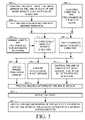
- FIG. 3is a simplified flowchart of a method in a handheld electronic device
- FIGS. 4-1 , 4 - 2 and 4 - 3are simplified illustrations of different display modes for images from the image sensor
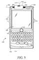
- FIG. 5is a simplified front view illustration of an exemplary handheld electronic device having a rotatable image sensor
- FIG. 6is a simplified side view illustration of the handheld electronic device of FIG. 5 along a section A to A′;
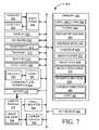
- FIG. 7is a simplified block diagram of an exemplary handheld electronic device
- a camera moduleis partially embedded in the housing of a handheld electronic device.
- An image sensorable to sense an image in a field of view that is centered around a line of sight is embedded in the camera module.
- the line of sightis perpendicular to a rotation axis of the camera module.
- a motor in the handheld electronic deviceis controllable by a processor of the handheld electronic device to adjust an angle of rotation of the camera module, and hence the line of sight, about the rotation axis.
- An image sensed by the image sensormay be displayed in a display of the handheld device.
- the handheld electronic devicemay comprise a tilt sensor to sense an orientation of the housing relative to a direction of gravity.
- the motormay be controlled to rotate the camera module, and hence the line of sight, about the rotation axis to achieve a particular angle between the line of sight and the direction of gravity.
- the motormay be further controlled to rotate the camera module, and hence the line of sight, about the rotation axis as the orientation changes to maintain the particular angle between the line of sight and the direction of gravity.
- the particular anglemay be preprogrammed to memory or may be set according to input received at a user-input element of the device.
- Image processingmay be employed to process the image sensed by the image sensor.
- One or more eventsmay be detected as a result of the image processing.
- the eventmay be appearance of an object or an obstacle or the detection of motion in the field of view.
- An audible effect or visual effect or bothmay be produced in response to detecting one or more events, in order to alert a user of the device to the detected event.
- FIG. 1is a simplified schematic illustration of a person 100 , the “user”, on a terrain 102 , holding and using a handheld electronic device 104 .
- a non-exhaustive list of examples for handheld electronic device 104includes a personal digital assistant (PDA), a mobile phone, a pager, a handheld gaming device, a handheld media player, a smartphone, an electronic mail client, an instant messaging client, and the like.
- PDApersonal digital assistant
- Line of sight 106While the user's attention and concentration are directed toward a display 108 of device 104 , this defines a line of sight 106 that is also directed toward display 108 .
- Peripheral visionis the ability to see objects and movement outside of the direct line of vision, and this ability varies from person to person due to factors such as age, training and eye health.
- Arrows 110 and 112illustrate the limits of the user's peripheral vision while the direct line of vision is line of sight 106 , and correspond to a portion 114 of terrain 102 .
- the length of portion 114 and its distance from the userare related to the angle of line of sight 106 .
- line of sight 106is such that portion 114 is only a few meters in length and is very close to the user.
- obstacle 116is illustrated as an object, in other examples obstacle 116 may be stairs, a hole, an animal or person, uneven terrain, or any other obstacle.
- the technology described hereinmay provide a user with enhanced visual awareness of his or her surroundings while the user's vision is directed to a display of a handheld electronic device.
- the enhanced visual awarenessmay relate to surroundings that would be within the user's peripheral vision if not obscured by the handheld electronic device.
- the technologymay provide the user with enhanced visual awareness of parts of portion 114 that are obscured by device 104 .
- the enhanced visual awarenessmay relate to surroundings that would not be within the user's peripheral vision.
- the technologymay provide the user with visual awareness of a portion 118 of terrain 102 that is further away from him or her than portion 114 .
- the technologymay provide the user with visual awareness of what is in front of him or her, as indicated by an arrow 120 .
- Device 104comprises an image sensor 122 that is able to sense images in its field of view, which is centered around the image sensor's line of sight. Images sensed by image sensor 122 may be displayed on display 108 .
- image sensor 122includes a charge-coupled device (CCD) sensor, a complementary metal-oxide-semiconductor (CMOS) sensor, and any other suitable image sensor.
- CCDcharge-coupled device
- CMOScomplementary metal-oxide-semiconductor
- Device 104also comprises a motor (not shown), with which device 104 can control the rotation of image sensor 122 about a rotation axis that is perpendicular to the image sensor's line of sight. Consequently, device 104 can change the line of sight of image sensor 122 “up” and “down” relative to the angle at which device 104 is held by the user.
- FIG. 1Three exemplary directions 124 , 126 and 128 for the line of sight of image sensor 122 are illustrated in FIG. 1 : a substantially “down” direction 124 , a substantially “down and forward” direction 126 , and a substantially “forward” direction 128 .
- image sensor 122may provide a view of portion 114 .
- image sensor 122may provide a view of farther portion 118 .
- image sensor 122provides a view in the direction of arrow 120 .
- the line of sight of image sensor 122may be controlled by device 104 in other directions not explicitly illustrated in FIG. 1 . Displaying the images sensed by image sensor 122 on display 108 may enhance the visual awareness of the surroundings of the user using device 104 .
- the usermay be able to control the rotation of image sensor 122 using any suitable user-input element of device 104 , for example, by rotating a trackball or a wheel, by pressing buttons, by pressing keys of a keyboard, by providing voice commands, by touching a touch screen or by sliding a finger on the touch screen.
- FIGS. 2-1 and 2 - 2illustrate device 104 being held by the user in different positions than the position in which it is held by the user in FIG. 1 .
- the technology described hereinmay enable device 104 to control the line of sight of image sensor 122 to be in a desired direction, regardless of the position of device 104 .
- the line of sightpoints in substantially “forward” direction 128 to provide a view in the direction of arrow 120 .
- other directions for the line of sight of image sensor 122are also contemplated.
- device 104may include a control mechanism, and may use the direction of gravity as a reference for this control mechanism.
- FIG. 3is a simplified flowchart of a method in a handheld device. As shown in FIG. 3 , one or more desired directions may be recorded in device 104 to indicate the angles between one or more desired directions and the direction of gravity.
- Device 104may enable the user to set one or more desired directions using any suitable user-input element of device 104 .
- device 104may enable the user to first control the rotation of image sensor 122 so the line of sight of image sensor 122 is in a particular direction, as explained hereinabove.
- device 104may enable the user to use a suitable user-input element of device 104 to set the particular direction as a desired direction, for example, by pressing a trackball, a wheel, a button or a key, by providing voice commands or by touching a touch screen.
- one or more desired directionsmay be preprogrammed in device 104 , for example, during manufacturing or with a downloadable software update downloaded to device 104 .
- device 104may enable the user to select which desired direction to use, as shown in 308 , for example via a graphical user interface displayed on display 108 .
- device 104may be able to automatically select between desired directions according to predefined criteria. For example, device 104 may select a substantially “down” direction if device 104 senses that it is stationary, and device 104 may select a substantially “forward” direction if device 104 senses that it is not stationary. In another example, device 104 may select a substantially “forward” direction if device 104 senses that it is stationary, and device 104 may select a substantially “down” direction if device 104 senses that it is not stationary. As shown in 312 , device 104 may enable the user to define the way in which device 104 is to select between desired directions according to the user's individual preferences, for example, via a graphical user interface displayed on display 108 .
- device 104may aim to control the line of sight of image sensor 122 to be in the selected desired direction, and may operate image sensor 122 to capture images, as shown in 316 .
- Device 104may optionally display images captured by image sensor 122 on display 108 , as shown in 318 .
- FIGS. 4-1 , 4 - 2 and 4 - 3Three examples are illustrated in FIGS. 4-1 , 4 - 2 and 4 - 3 , respectively.
- FIG. 4-1illustrates an exemplary “full screen” display mode in which an image 400 from image sensor 122 occupies most or all of display 108 .
- FIG. 4-2illustrates a “small window” display mode, applicable when the user is operating an application running on device 104 that has a graphical user interface (GUI) 402 .
- GUIgraphical user interface
- image 400 from image sensor 122occupies a smaller area of display 108 than the area occupied by the graphical user interface 402 of the application.
- FIG. 4-3illustrates a “picture in picture” display mode, applicable when the user is operating an application running on device 104 that has GUI 402 .
- image 400 from image sensor 122is displayed in “picture in picture” fashion, so that it obscures a portion of the area occupied by GUI 402 on display 108 .
- image 400is shown in FIG. 4-3 in the top left corner of display 108 , device 104 may place image 400 in a different portion of display 108 so as to minimize interference with the operation of the application having GUI 402 .
- GUI 402includes an area designated for data entry and the application is awaiting input from the user
- device 104may assess whether image 400 obscures the area designated for data entry and may place image 400 in different portion of display 108 so as not to obscure or to obscure less of the area designated for data entry.
- the usermay be able to select a display mode or to switch between different display modes using any suitable user-input element of device 104 , such as, for example, a trackball, a wheel, a button, a key, an audio input element or a touch screen.
- any suitable user-input element of device 104such as, for example, a trackball, a wheel, a button, a key, an audio input element or a touch screen.
- Device 104may incorporate image processing technology and as shown at 320 , device 104 may use this image processing technology to process images captured by image sensor 122 . Using the image processing technology, device 104 may be able to detect events that appear in images captured by image sensor 122 . Such events may be, for example, appearance of an object, detection of motion of an object, detection of an obstacle and so forth.
- device 104detects such an event, and at 324 , device 104 aims to increase awareness of the user to the event by producing one or more visual effects or one or more audible effects or both.
- a non-exhaustive list of examples of visual effectsincludes: displaying image 400 on display 108 , if not yet displayed; displaying a visual alert on display 108 , for example, a flickering image 404 , shown in FIG. 4-2 , or by flashing an edge 406 of image 400 ; switching between display modes of image 400 ; or resizing image 400 on display 108 .
- device 104may set the size of image 400 to a relatively large size if motion of an object is captured in image 400 or if a potential obstacle is captured in image 400 or both, and may set the size of image 400 to a relatively small size otherwise.
- Other suitable visual effectsare also contemplated.
- a non-exhaustive list of examples of audible effectsincludes sounding an audible alert via an audio output element of device 104 .
- FIG. 5is a simplified front view illustration of an exemplary handheld electronic device 500
- FIG. 6is a simplified side view illustration of device 500 along a section A-A′
- FIG. 7is a simplified block diagram of device 500 .
- Device 500is an example of device 104 .
- Device 500has a housing 502 that encloses the different components of device 500 .
- FIGS. 5 and 6show housing 502 as made of a single piece.
- housing 502may be made of one, two or more pieces connected together.
- a keyboardmay slide in and out on a main part of the housing.
- housing 502may have two or more sections that fold via a hinge.
- Device 500includes a processor 504 enclosed within housing 502 .
- Device 500also includes a memory 506 , a display 508 and a keyboard 510 , all coupled to processor 504 .
- Keyboard 510may be embedded in full or in part within display 508 , i.e. display 508 may be a “touch screen”.
- Device 500may include one or more tactile user-input elements devices coupled to processor 504 .
- a non-exhaustive list of examples for such tactile user-input elementsincludes a trackball 512 that is rollable and pressable, a wheel 514 that is rotatable and pressable, and buttons 516 that may have programmable functionality.
- Device 500may include an audio coder-decoder (codec) 518 coupled to processor 504 .
- Device 500may include an audio input element 520 , for example a microphone, and an audio output element 522 , for example, a speaker, both coupled to codec 518 .
- Device 500may include one or more connectors (not shown) to connect to an external audio input element or an external audio output element or both. The one or more connectors may be included in device 500 instead of, or in addition to, audio input element 520 or audio output element 522 or both.
- Device 500may include additional user interface elements that are not shown in FIGS. 5 , 6 and 7 .
- Device 500includes a camera module 524 that is partially embedded in housing 502 and is rotatable about a rotation axis 526 .
- An image sensor 528 embedded in camera module 524has a line of sight 530 that is perpendicular to rotation axis 526 at any rotational position of camera module 524 about rotation axis 526 .
- FIG. 6shows camera module 524 in an exemplary rotational position in which image sensor 528 has a line of sight 530 .
- a second exemplary line of sight 532 for another rotational position of camera module 524is also shown in FIG. 6 .
- Section A-A′ shown in FIG. 5is a plane defined by lines of sight 530 and 532 .
- Rotation of camera module 524can be expressed by an angle 534 between line of sight 530 and an arbitrary reference axis 536 that is perpendicular to rotation axis 526 .
- Device 500includes a motor 538 that is coupled to housing 502 and to camera module 524 , and is controllable by processor 504 to manipulate angle 534 .
- Device 500includes an angle indicator 540 , for example an encoder, which can sense angle 534 and report its value or a correlated value to processor 504 . It may be noted that many different mechanical implementations are possible for elements 524 , 528 , 538 and 540 . For clarity of the description, elements 524 , 528 , 538 and 540 are presented in FIGS. 5 and 6 in a simplified manner that does not presume any particular mechanical implementation.
- Device 500includes a tilt sensor 541 , for example, an accelerometer or a gyroscope.
- Tilt sensor 541may be a Micro Electrical Mechanical System (MEMS) device.
- MEMSMicro Electrical Mechanical System
- Analog Devices, Inc. of Norwood, Mass., USAproduces a family of integrated MEMS accelerometers and a family of integrated MEMS gyroscopes.
- Tilt sensor 541provides measurements in at least two perpendicular axes and is mounted in device 500 so that these two axes are parallel to the plane defined by lines of sight 530 and 532 .
- FIG. 6shows two perpendicular axes 542 and 544 in which orientation sensor 542 provide measurements.
- axis 544is shown parallel to an edge of housing 502 and intersecting with rotation axis 526 , but this relationship between axis 544 , housing 502 and rotation axis 526 is not an essential requirement.
- Tilt sensor 541is able to indicate a direction of gravity 546 relative to axis 542 and 544 .
- the type of indicationmay vary according to the design of tilt sensor 541 .
- tilt sensor 541may output a rectangular wave and may use pulse width modulation (PWM) to reflect an angle 548 between axis 542 and direction of gravity 546 .
- PWMpulse width modulation
- Processor 504may calculate an angle 550 between the direction of gravity 546 and line of sight 530 from the following information: a) angle 548 corresponding to the orientation of housing 502 relative to the direction of gravity 546 , b) an angle 551 between axis 544 and reference axis 536 , and c) angle 534 corresponding to the rotation of camera module 524 about rotation axis 526 relative to reference axis 536 .
- Device 500includes a camera control module 552 that operates image sensor 528 for capturing video images, still images, or both.
- Device 500may optionally include a wireless communication interface 554 , compatible with a wireless communication standard, coupled to processor 504 and including at least a radio 556 and one or more antennae 558 .
- wireless communication interface 554and a communication infrastructure (not shown) that is external to device 500 , device 500 may be able to establish voice, video and/or data communication sessions with other devices (not shown).
- a non-exhaustive list of examples for data communication sessionsincludes sending and receiving electronic mail (email), instant messages, paging messages, short message service (SMS) messages, and any other suitable data communication sessions.
- memory 506may store respective software modules to be executed by processor 504 , for example, an email software module 560 , an SMS software module 562 , a paging software module 564 and an instant messaging software module 566 .
- Memory 506may store application modules, for example, an “address book” application module 568 to manage information related to individuals and organizations, a “calendar” application module 570 to manage information related to calendar events such as appointments and meetings, and a media player module 572 .
- Memory 504may store media files 574 including audio, video, and/or stills pictures information. Any of media files 574 may include information captured by image sensor 528 .
- Media player 572may be able to play media files 574 using display 508 or audio output element 522 or both, as appropriate.
- Memory 506may store an image processing module 576 able to detect motion and/or potential obstacles in images captured by image sensor 528 .
- Memory 104may store one or more desired directions 578 so to indicate the angles between a plurality of desired directions of the line of sight of image sensor 122 and the direction of gravity.
- Memory 104may store an indication 580 of the direction of a current line of sight of image sensor 122 and the direction of gravity.
- Memory 104may store executable code 582 which, when executed by processor 504 , causes device 500 to perform any of the methods described herein.
- a non-exhaustive list of examples for standards with which wireless communication interface 544 may complyincludes Direct Sequence-Code Division Multiple Access (DS-CDMA) cellular radiotelephone communication, Global System for Mobile Communications (GSM) cellular radiotelephone, North American Digital Cellular (NADC) cellular radiotelephone, Time Division Multiple Access (TDMA), Extended-TDMA (E-TDMA) cellular radiotelephone, wideband CDMA (WCDMA), General Packet Radio Service (GPRS), Enhanced Data for GSM Evolution (EDGE), 3G and 4G communication.
- DS-CDMADirect Sequence-Code Division Multiple Access
- GSMGlobal System for Mobile Communications
- NADCNorth American Digital Cellular
- TDMATime Division Multiple Access
- E-TDMAExtended-TDMA
- WCDMAWideband CDMA
- GPRSGeneral Packet Radio Service
- EDGEEnhanced Data for GSM Evolution
- device 500may be “802.11-enabled”, and wireless communication interface 544 may comply with one or more standards of the 802.11 family of standards defined by the Institute of Electrical and Electronic Engineers (IEEE) for Wireless LAN MAC and Physical layer (PHY) specifications.
- IEEEInstitute of Electrical and Electronic Engineers
- PHYPhysical layer
- processor 504includes microprocessors, microcontrollers, central processing units (CPU), digital signal processors (DSP), reduced instruction set computers (RISC), complex instruction set computers (CISC) and the like.
- processor 502may comprise more than one processing unit, may be part of an application specific integrated circuit (ASIC) or may be a part of an application specific standard product (ASSP).
- ASICapplication specific integrated circuit
- ASSPapplication specific standard product
- a non-exhaustive list of examples for memory 506includes any combination of the following:
- a) semiconductor devicessuch as registers, latches, read only memory (ROM), mask ROM, electrically erasable programmable read only memory devices (EEPROM), flash memory devices, non-volatile random access memory devices (NVRAM), synchronous dynamic random access memory (SDRAM) devices, RAMBUS dynamic random access memory (RDRAM) devices, double data rate (DDR) memory devices, static random access memory (SRAM), universal serial bus (USB) removable memory, and the like;
- optical devicessuch as compact disk read only memory (CD ROM), and the like;
- c) magnetic devicessuch as a hard disk, a floppy disk, a magnetic tape, and the like.
- antennae 558includes dipole antennae, monopole antennae, multilayer ceramic antennae, planar inverted-F antennae, loop antennae, shot antennae, dual antennae, omnidirectional antennae and any other suitable antennae.
Landscapes
- Engineering & Computer Science (AREA)
- Multimedia (AREA)
- Signal Processing (AREA)
- Human Computer Interaction (AREA)
- User Interface Of Digital Computer (AREA)
Abstract
Description
Claims (21)
Priority Applications (1)
| Application Number | Priority Date | Filing Date | Title |
|---|---|---|---|
| US12/371,768US8159363B2 (en) | 2009-02-16 | 2009-02-16 | Using gravity to direct a rotatable camera in a handheld electronic device |
Applications Claiming Priority (1)
| Application Number | Priority Date | Filing Date | Title |
|---|---|---|---|
| US12/371,768US8159363B2 (en) | 2009-02-16 | 2009-02-16 | Using gravity to direct a rotatable camera in a handheld electronic device |
Publications (2)
| Publication Number | Publication Date |
|---|---|
| US20100207774A1 US20100207774A1 (en) | 2010-08-19 |
| US8159363B2true US8159363B2 (en) | 2012-04-17 |
Family
ID=42559388
Family Applications (1)
| Application Number | Title | Priority Date | Filing Date |
|---|---|---|---|
| US12/371,768Active2030-12-21US8159363B2 (en) | 2009-02-16 | 2009-02-16 | Using gravity to direct a rotatable camera in a handheld electronic device |
Country Status (1)
| Country | Link |
|---|---|
| US (1) | US8159363B2 (en) |
Cited By (9)
| Publication number | Priority date | Publication date | Assignee | Title |
|---|---|---|---|---|
| US20120229447A1 (en)* | 2011-03-08 | 2012-09-13 | Nokia Corporation | Apparatus and associated methods |
| US8979398B2 (en) | 2013-04-16 | 2015-03-17 | Microsoft Technology Licensing, Llc | Wearable camera |
| US9282244B2 (en) | 2013-03-14 | 2016-03-08 | Microsoft Technology Licensing, Llc | Camera non-touch switch |
| US9444996B2 (en) | 2013-04-26 | 2016-09-13 | Microsoft Technology Licensing, Llc | Camera tap switch |
| US9451178B2 (en) | 2014-05-22 | 2016-09-20 | Microsoft Technology Licensing, Llc | Automatic insertion of video into a photo story |
| TWI556156B (en)* | 2012-08-20 | 2016-11-01 | 宏達國際電子股份有限公司 | Method of adjusting image display direction and related device thereof |
| US9503644B2 (en) | 2014-05-22 | 2016-11-22 | Microsoft Technology Licensing, Llc | Using image properties for processing and editing of multiple resolution images |
| US10750116B2 (en) | 2014-05-22 | 2020-08-18 | Microsoft Technology Licensing, Llc | Automatically curating video to fit display time |
| US11568566B2 (en) | 2016-07-08 | 2023-01-31 | Toyota Motor Engineering & Manufacturing North America. Inc. | Aligning vision-assist device cameras based on physical characteristics of a user |
Families Citing this family (20)
| Publication number | Priority date | Publication date | Assignee | Title |
|---|---|---|---|---|
| US8485179B1 (en) | 2009-02-23 | 2013-07-16 | Trudell Medical International | Oscillating positive expiratory pressure device |
| US9149589B2 (en)* | 2009-02-23 | 2015-10-06 | Trudell Medical International | Method and device for performing orientation dependent oscillating positive expiratory pressure therapy |
| CN101827212A (en)* | 2009-03-02 | 2010-09-08 | 鸿富锦精密工业(深圳)有限公司 | Image pick-up device and imaging angle adjusting method thereof |
| US9460029B2 (en) | 2012-03-02 | 2016-10-04 | Microsoft Technology Licensing, Llc | Pressure sensitive keys |
| US9298236B2 (en) | 2012-03-02 | 2016-03-29 | Microsoft Technology Licensing, Llc | Multi-stage power adapter configured to provide a first power level upon initial connection of the power adapter to the host device and a second power level thereafter upon notification from the host device to the power adapter |
| US9075566B2 (en) | 2012-03-02 | 2015-07-07 | Microsoft Technoogy Licensing, LLC | Flexible hinge spine |
| US9706089B2 (en) | 2012-03-02 | 2017-07-11 | Microsoft Technology Licensing, Llc | Shifted lens camera for mobile computing devices |
| US9870066B2 (en) | 2012-03-02 | 2018-01-16 | Microsoft Technology Licensing, Llc | Method of manufacturing an input device |
| US20130300590A1 (en) | 2012-05-14 | 2013-11-14 | Paul Henry Dietz | Audio Feedback |
| US10031556B2 (en) | 2012-06-08 | 2018-07-24 | Microsoft Technology Licensing, Llc | User experience adaptation |
| US9137517B2 (en)* | 2012-10-05 | 2015-09-15 | Blackberry Limited | Methods and devices for generating a stereoscopic image |
| US9148651B2 (en)* | 2012-10-05 | 2015-09-29 | Blackberry Limited | Methods and devices for generating a stereoscopic image |
| US9304549B2 (en) | 2013-03-28 | 2016-04-05 | Microsoft Technology Licensing, Llc | Hinge mechanism for rotatable component attachment |
| WO2014166521A1 (en)* | 2013-04-09 | 2014-10-16 | Huawei Technologies Co., Ltd. | Mobile electronic device with a rotatable camera |
| KR20150042574A (en)* | 2013-10-11 | 2015-04-21 | 엘지전자 주식회사 | Mobile terminal and method for controlling thereof |
| US10171729B2 (en)* | 2015-02-28 | 2019-01-01 | Huawei Technologies Co., Ltd. | Directional adjustment for a camera based on exposure quality information |
| CN105049813A (en)* | 2015-08-11 | 2015-11-11 | 小米科技有限责任公司 | Method, device and terminal controlling video image |
| WO2019033289A1 (en)* | 2017-08-16 | 2019-02-21 | 天彩电子(深圳)有限公司 | System and method for expanding field of view of video camera |
| CN109981827B (en)* | 2017-12-28 | 2021-02-26 | Oppo广东移动通信有限公司 | Terminal equipment and its camera assembly |
| CN115480632A (en)* | 2021-05-31 | 2022-12-16 | 华为技术有限公司 | A display device with a camera component and a camera angle adjustment method |
Citations (30)
| Publication number | Priority date | Publication date | Assignee | Title |
|---|---|---|---|---|
| US5412417A (en) | 1992-04-17 | 1995-05-02 | Toshiba Corporation | Video telephone device with automatic video camera angle adjustment |
| US5963749A (en) | 1998-02-09 | 1999-10-05 | Nicholson; Lynn | Self-leveling invertible camera stabilizer |
| US6097423A (en) | 1997-06-06 | 2000-08-01 | Karl Storz Imaging, Inc. | Image orientation for endoscopic video displays |
| JP2002050978A (en) | 2000-02-29 | 2002-02-15 | Kddi Corp | Portable information terminal, digital camera for portable information terminal, and digital camera device connected to portable information terminal |
| EP1220143A2 (en) | 2000-12-25 | 2002-07-03 | Hitachi, Ltd. | Electronics device applying an image sensor |
| US6535114B1 (en) | 2000-03-22 | 2003-03-18 | Toyota Jidosha Kabushiki Kaisha | Method and apparatus for environment recognition |
| US6611661B2 (en) | 2001-02-14 | 2003-08-26 | Clean Line Incorporated | Self-leveling camera |
| US20030227564A1 (en)* | 2002-06-05 | 2003-12-11 | Samsung Electro-Mechanics Co., Ltd. | Camera drive unit and cellular phone equipped with camera drive unit |
| US20040100479A1 (en)* | 2002-05-13 | 2004-05-27 | Masao Nakano | Portable information terminal, display control device, display control method, and computer readable program therefor |
| US6747690B2 (en) | 2000-07-11 | 2004-06-08 | Phase One A/S | Digital camera with integrated accelerometers |
| US6751410B1 (en) | 2003-07-10 | 2004-06-15 | Hewlett-Packard Development Company, L.P. | Inertial camera stabilization apparatus and method |
| US20040119836A1 (en) | 1998-06-26 | 2004-06-24 | Takashi Kitaguchi | Apparatus and method for correction of a deviation of digital camera |
| US6820980B1 (en) | 2001-03-23 | 2004-11-23 | Panavision, Inc. | Automatic pan and tilt compensation system for a camera support structure |
| US20050007467A1 (en) | 2003-07-07 | 2005-01-13 | Battles Amy E. | System and method for setting an image capture device to an operational mode |
| US20050264653A1 (en) | 2004-05-27 | 2005-12-01 | Starkweather James A | Portable electronic device with adjustable image capture orientation and method therefore |
| US20060074549A1 (en)* | 2004-10-01 | 2006-04-06 | Hitachi, Ltd. | Navigation apparatus |
| US7054552B2 (en) | 2004-06-25 | 2006-05-30 | Nokia Corporation | Vertical and horizontal pictures taken without camera rotation |
| US20060177103A1 (en) | 2005-01-07 | 2006-08-10 | Evan Hildreth | Optical flow based tilt sensor |
| US20060204232A1 (en) | 2005-02-01 | 2006-09-14 | Harvey Weinberg | Camera with acceleration sensor |
| US20060206003A1 (en) | 2005-02-17 | 2006-09-14 | Hoeg Hans D | Image orienting coupling assembly |
| JP2006301838A (en) | 2005-04-19 | 2006-11-02 | Hitachi Omron Terminal Solutions Corp | Content display control system, content display device, content display control method, and computer software |
| US7134992B2 (en) | 2004-01-09 | 2006-11-14 | Karl Storz Development Corp. | Gravity referenced endoscopic image orientation |
| US7138979B2 (en) | 2004-08-27 | 2006-11-21 | Motorola, Inc. | Device orientation based input signal generation |
| JP2007027950A (en) | 2005-07-13 | 2007-02-01 | Sanyo Electric Co Ltd | Portable telephone, photography method and program |
| US20070071438A1 (en) | 2005-09-27 | 2007-03-29 | Universal Scientific Industrial Co., Ltd. | Handheld electronic device including a rotatable camera unit |
| JP2007121491A (en) | 2005-10-26 | 2007-05-17 | Konica Minolta Medical & Graphic Inc | Processing method for heat developable silver salt photosensitive material |
| US20070120960A1 (en) | 2005-11-11 | 2007-05-31 | Hon Hai Precision Industry Co., Ltd. | Portable electronic device with a rotatable camera module |
| US20070273752A1 (en) | 2004-04-15 | 2007-11-29 | Agere Systems Incorporated | Retractable rotatable camera module for mobile communication device and method of operation thereof |
| US7307653B2 (en) | 2001-10-19 | 2007-12-11 | Nokia Corporation | Image stabilizer for a microcamera module of a handheld device, and method for stabilizing a microcamera module of a handheld device |
| US20110141254A1 (en)* | 2009-11-17 | 2011-06-16 | Roebke Mark J | Systems and methods for augmented reality |
- 2009
- 2009-02-16USUS12/371,768patent/US8159363B2/enactiveActive
Patent Citations (30)
| Publication number | Priority date | Publication date | Assignee | Title |
|---|---|---|---|---|
| US5412417A (en) | 1992-04-17 | 1995-05-02 | Toshiba Corporation | Video telephone device with automatic video camera angle adjustment |
| US6097423A (en) | 1997-06-06 | 2000-08-01 | Karl Storz Imaging, Inc. | Image orientation for endoscopic video displays |
| US5963749A (en) | 1998-02-09 | 1999-10-05 | Nicholson; Lynn | Self-leveling invertible camera stabilizer |
| US20040119836A1 (en) | 1998-06-26 | 2004-06-24 | Takashi Kitaguchi | Apparatus and method for correction of a deviation of digital camera |
| JP2002050978A (en) | 2000-02-29 | 2002-02-15 | Kddi Corp | Portable information terminal, digital camera for portable information terminal, and digital camera device connected to portable information terminal |
| US6535114B1 (en) | 2000-03-22 | 2003-03-18 | Toyota Jidosha Kabushiki Kaisha | Method and apparatus for environment recognition |
| US6747690B2 (en) | 2000-07-11 | 2004-06-08 | Phase One A/S | Digital camera with integrated accelerometers |
| EP1220143A2 (en) | 2000-12-25 | 2002-07-03 | Hitachi, Ltd. | Electronics device applying an image sensor |
| US6611661B2 (en) | 2001-02-14 | 2003-08-26 | Clean Line Incorporated | Self-leveling camera |
| US6820980B1 (en) | 2001-03-23 | 2004-11-23 | Panavision, Inc. | Automatic pan and tilt compensation system for a camera support structure |
| US7307653B2 (en) | 2001-10-19 | 2007-12-11 | Nokia Corporation | Image stabilizer for a microcamera module of a handheld device, and method for stabilizing a microcamera module of a handheld device |
| US20040100479A1 (en)* | 2002-05-13 | 2004-05-27 | Masao Nakano | Portable information terminal, display control device, display control method, and computer readable program therefor |
| US20030227564A1 (en)* | 2002-06-05 | 2003-12-11 | Samsung Electro-Mechanics Co., Ltd. | Camera drive unit and cellular phone equipped with camera drive unit |
| US20050007467A1 (en) | 2003-07-07 | 2005-01-13 | Battles Amy E. | System and method for setting an image capture device to an operational mode |
| US6751410B1 (en) | 2003-07-10 | 2004-06-15 | Hewlett-Packard Development Company, L.P. | Inertial camera stabilization apparatus and method |
| US7134992B2 (en) | 2004-01-09 | 2006-11-14 | Karl Storz Development Corp. | Gravity referenced endoscopic image orientation |
| US20070273752A1 (en) | 2004-04-15 | 2007-11-29 | Agere Systems Incorporated | Retractable rotatable camera module for mobile communication device and method of operation thereof |
| US20050264653A1 (en) | 2004-05-27 | 2005-12-01 | Starkweather James A | Portable electronic device with adjustable image capture orientation and method therefore |
| US7054552B2 (en) | 2004-06-25 | 2006-05-30 | Nokia Corporation | Vertical and horizontal pictures taken without camera rotation |
| US7138979B2 (en) | 2004-08-27 | 2006-11-21 | Motorola, Inc. | Device orientation based input signal generation |
| US20060074549A1 (en)* | 2004-10-01 | 2006-04-06 | Hitachi, Ltd. | Navigation apparatus |
| US20060177103A1 (en) | 2005-01-07 | 2006-08-10 | Evan Hildreth | Optical flow based tilt sensor |
| US20060204232A1 (en) | 2005-02-01 | 2006-09-14 | Harvey Weinberg | Camera with acceleration sensor |
| US20060206003A1 (en) | 2005-02-17 | 2006-09-14 | Hoeg Hans D | Image orienting coupling assembly |
| JP2006301838A (en) | 2005-04-19 | 2006-11-02 | Hitachi Omron Terminal Solutions Corp | Content display control system, content display device, content display control method, and computer software |
| JP2007027950A (en) | 2005-07-13 | 2007-02-01 | Sanyo Electric Co Ltd | Portable telephone, photography method and program |
| US20070071438A1 (en) | 2005-09-27 | 2007-03-29 | Universal Scientific Industrial Co., Ltd. | Handheld electronic device including a rotatable camera unit |
| JP2007121491A (en) | 2005-10-26 | 2007-05-17 | Konica Minolta Medical & Graphic Inc | Processing method for heat developable silver salt photosensitive material |
| US20070120960A1 (en) | 2005-11-11 | 2007-05-31 | Hon Hai Precision Industry Co., Ltd. | Portable electronic device with a rotatable camera module |
| US20110141254A1 (en)* | 2009-11-17 | 2011-06-16 | Roebke Mark J | Systems and methods for augmented reality |
Non-Patent Citations (4)
| Title |
|---|
| Adam Pash , "Email 'n Walk lets you multitask without getting hit by a car", May 15, 2009. |
| Dolezel, Tomas, Extended European Search Report for E09152957.8, Jun. 9, 2009. |
| Steves Digicams, "Nikon Coolpix S4 Review", Nov. 16, 2005. |
| The Imaging Resource, "Quick Review-Nikon Coolpix 2500 Digital Camera", The most interesting design feature is the rotating lens, which swivels approximately 230 degrees inside the camera's frame, to a range of shooting angles. Feb. 21, 2002. |
Cited By (12)
| Publication number | Priority date | Publication date | Assignee | Title |
|---|---|---|---|---|
| US20120229447A1 (en)* | 2011-03-08 | 2012-09-13 | Nokia Corporation | Apparatus and associated methods |
| US9035940B2 (en)* | 2011-03-08 | 2015-05-19 | Nokia Corporation | Apparatus and associated methods |
| TWI556156B (en)* | 2012-08-20 | 2016-11-01 | 宏達國際電子股份有限公司 | Method of adjusting image display direction and related device thereof |
| US9282244B2 (en) | 2013-03-14 | 2016-03-08 | Microsoft Technology Licensing, Llc | Camera non-touch switch |
| US9516227B2 (en) | 2013-03-14 | 2016-12-06 | Microsoft Technology Licensing, Llc | Camera non-touch switch |
| US8979398B2 (en) | 2013-04-16 | 2015-03-17 | Microsoft Technology Licensing, Llc | Wearable camera |
| US9444996B2 (en) | 2013-04-26 | 2016-09-13 | Microsoft Technology Licensing, Llc | Camera tap switch |
| US9451178B2 (en) | 2014-05-22 | 2016-09-20 | Microsoft Technology Licensing, Llc | Automatic insertion of video into a photo story |
| US9503644B2 (en) | 2014-05-22 | 2016-11-22 | Microsoft Technology Licensing, Llc | Using image properties for processing and editing of multiple resolution images |
| US10750116B2 (en) | 2014-05-22 | 2020-08-18 | Microsoft Technology Licensing, Llc | Automatically curating video to fit display time |
| US11184580B2 (en) | 2014-05-22 | 2021-11-23 | Microsoft Technology Licensing, Llc | Automatically curating video to fit display time |
| US11568566B2 (en) | 2016-07-08 | 2023-01-31 | Toyota Motor Engineering & Manufacturing North America. Inc. | Aligning vision-assist device cameras based on physical characteristics of a user |
Also Published As
| Publication number | Publication date |
|---|---|
| US20100207774A1 (en) | 2010-08-19 |
Similar Documents
| Publication | Publication Date | Title |
|---|---|---|
| US8159363B2 (en) | Using gravity to direct a rotatable camera in a handheld electronic device | |
| CA2691671C (en) | Using gravity to direct a rotatable camera in a mobile device | |
| EP3671406B1 (en) | Method, apparatus and storage medium for displaying shortcut operation panel | |
| US20150213580A1 (en) | Display control apparatus, display control method, program, and display device | |
| EP2428864B1 (en) | Camera-based orientation fix from portrait to landscape | |
| US8111247B2 (en) | System and method for changing touch screen functionality | |
| JP5370259B2 (en) | Portable electronic devices | |
| JP5925656B2 (en) | Image display control device, image display device, program, and image display method | |
| US20100330912A1 (en) | Method and apparatus for activating one or more remote features | |
| US11150794B2 (en) | Electronic device control in response to finger rotation upon fingerprint sensor and corresponding methods | |
| CN107515669B (en) | Display method and device | |
| KR20160079444A (en) | Digital device and controlling method thereof | |
| CN110753196A (en) | A terminal device and audio output method | |
| JP2020017218A (en) | Electronic device, control program, and display control method |
Legal Events
| Date | Code | Title | Description |
|---|---|---|---|
| AS | Assignment | Owner name:RESEARCH IN MOTION LIMITED, CANADA Free format text:ASSIGNMENT OF ASSIGNORS INTEREST;ASSIGNOR:SONG, JAE RYEE;REEL/FRAME:022287/0224 Effective date:20080923 | |
| STCF | Information on status: patent grant | Free format text:PATENTED CASE | |
| FEPP | Fee payment procedure | Free format text:PAYOR NUMBER ASSIGNED (ORIGINAL EVENT CODE: ASPN); ENTITY STATUS OF PATENT OWNER: LARGE ENTITY | |
| FPAY | Fee payment | Year of fee payment:4 | |
| AS | Assignment | Owner name:BLACKBERRY LIMITED, ONTARIO Free format text:CHANGE OF NAME;ASSIGNOR:RESEARCH IN MOTION LIMITED;REEL/FRAME:037893/0239 Effective date:20130709 | |
| MAFP | Maintenance fee payment | Free format text:PAYMENT OF MAINTENANCE FEE, 8TH YEAR, LARGE ENTITY (ORIGINAL EVENT CODE: M1552); ENTITY STATUS OF PATENT OWNER: LARGE ENTITY Year of fee payment:8 | |
| AS | Assignment | Owner name:MALIKIE INNOVATIONS LIMITED, IRELAND Free format text:ASSIGNMENT OF ASSIGNORS INTEREST;ASSIGNOR:BLACKBERRY LIMITED;REEL/FRAME:064104/0103 Effective date:20230511 | |
| AS | Assignment | Owner name:MALIKIE INNOVATIONS LIMITED, IRELAND Free format text:NUNC PRO TUNC ASSIGNMENT;ASSIGNOR:BLACKBERRY LIMITED;REEL/FRAME:064270/0001 Effective date:20230511 | |
| MAFP | Maintenance fee payment | Free format text:PAYMENT OF MAINTENANCE FEE, 12TH YEAR, LARGE ENTITY (ORIGINAL EVENT CODE: M1553); ENTITY STATUS OF PATENT OWNER: LARGE ENTITY Year of fee payment:12 |