US8159153B2 - LED light sources with improved thermal compensation - Google Patents
LED light sources with improved thermal compensationDownload PDFInfo
- Publication number
- US8159153B2 US8159153B2US12/896,615US89661510AUS8159153B2US 8159153 B2US8159153 B2US 8159153B2US 89661510 AUS89661510 AUS 89661510AUS 8159153 B2US8159153 B2US 8159153B2
- Authority
- US
- United States
- Prior art keywords
- light source
- temperature
- light
- led
- primary
- Prior art date
- Legal status (The legal status is an assumption and is not a legal conclusion. Google has not performed a legal analysis and makes no representation as to the accuracy of the status listed.)
- Expired - Fee Related
Links
Images


Classifications
- H—ELECTRICITY
- H05—ELECTRIC TECHNIQUES NOT OTHERWISE PROVIDED FOR
- H05B—ELECTRIC HEATING; ELECTRIC LIGHT SOURCES NOT OTHERWISE PROVIDED FOR; CIRCUIT ARRANGEMENTS FOR ELECTRIC LIGHT SOURCES, IN GENERAL
- H05B45/00—Circuit arrangements for operating light-emitting diodes [LED]
- H05B45/30—Driver circuits
- H05B45/395—Linear regulators
- H—ELECTRICITY
- H05—ELECTRIC TECHNIQUES NOT OTHERWISE PROVIDED FOR
- H05B—ELECTRIC HEATING; ELECTRIC LIGHT SOURCES NOT OTHERWISE PROVIDED FOR; CIRCUIT ARRANGEMENTS FOR ELECTRIC LIGHT SOURCES, IN GENERAL
- H05B45/00—Circuit arrangements for operating light-emitting diodes [LED]
- H05B45/20—Controlling the colour of the light
- H05B45/28—Controlling the colour of the light using temperature feedback
- Y—GENERAL TAGGING OF NEW TECHNOLOGICAL DEVELOPMENTS; GENERAL TAGGING OF CROSS-SECTIONAL TECHNOLOGIES SPANNING OVER SEVERAL SECTIONS OF THE IPC; TECHNICAL SUBJECTS COVERED BY FORMER USPC CROSS-REFERENCE ART COLLECTIONS [XRACs] AND DIGESTS
- Y02—TECHNOLOGIES OR APPLICATIONS FOR MITIGATION OR ADAPTATION AGAINST CLIMATE CHANGE
- Y02B—CLIMATE CHANGE MITIGATION TECHNOLOGIES RELATED TO BUILDINGS, e.g. HOUSING, HOUSE APPLIANCES OR RELATED END-USER APPLICATIONS
- Y02B20/00—Energy efficient lighting technologies, e.g. halogen lamps or gas discharge lamps
- Y02B20/30—Semiconductor lamps, e.g. solid state lamps [SSL] light emitting diodes [LED] or organic LED [OLED]
Definitions
- LEDsLight emitting diodes
- Improvements in these deviceshave resulted in their use in light fixtures designed to replace conventional incandescent and fluorescent light sources.
- the LEDshave significantly longer lifetimes and, in some cases, significantly higher efficiency for converting electric energy to light.
- LED-based light sourcesthat are designed to replace conventional white light sources utilize a “white LED” in combination with a red LED.
- the white LEDis typically constructed from a blue LED that is covered with a phosphor layer that converts a portion of the blue light to yellow light. If the ratio of blue to yellow light in the output spectrum is correct, the light appears to be “white” to a human observer. For some applications, the “color temperature” of the resulting light source is too high. In addition, the output spectrum is less than ideal in terms of its color-rendering index. Accordingly, a red LED can be incorporated with the white LED to fill in the spectrum at long wavelengths and to shift the perceived color of the light source to a lower color temperature.
- a light source constructed from two different types of LEDswill be referred to as a compound light source.
- the electrical conversion efficiency of an LEDtypically decreases with increasing temperature. For any given increase in operating temperature, the amount of the decrease depends on the particular type of LED.
- the electrical conversion efficiency of red LEDsdecreases with temperature faster than the electrical conversion efficiency of blue LEDs.
- the ratio of red light to blue light in the above-described white light sourcechanges with temperature. This leads to a color shift as the temperature of operation increases.
- the LEDsIn light sources that are designed to replace conventional incandescent or fluorescent sources, the LEDs often operate at temperatures that are significantly above ambient. The exact operating temperature depends on the specific light source fixture and the ambient temperature.
- the output wavelength of the LEDsalso shifts with temperature.
- the wavelength of light from red LEDsincreases with increasing temperature. This shift results in an additional shift in the color temperature of the light source. Accordingly, providing a compound light source that produces light of a predetermined color temperature at all operating temperatures presents engineering challenges.
- the present inventionincludes a compound light source that compensates for changes in electrical conversion efficiency with increasing operating temperature.
- the compound light sourcegenerates light of a design intensity at a design temperature in response to a drive current flowing through the light source.
- the light sourceincludes a primary light source and a compensating light source.
- the primary and compensating light sourcesconvert an electrical current passing therethrough to light, each light source being characterized by an electrical conversion efficiency that decreases with increasing temperature and that also decreases with increasing current.
- the compound light sourcealso includes a temperature sensor that measures the temperature of the primary light source and a current splitting circuit that divides the drive current between the primary and compensating light sources in response to the measured temperature to compensate for the decrease in efficiency of the primary light source with temperature above the design temperature.
- FIG. 1illustrates a prior art white light source that utilizes a red LED to enhance the output spectrum.
- FIG. 2is a schematic diagram of one embodiment of a light source according to the present invention.
- FIG. 3is a schematic drawing of another embodiment of a light according to the present invention.
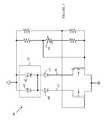
- FIG. 4illustrates another embodiment of a light source according to the present invention.
- Light source 20includes a blue-emitting LED 21 that is covered by a layer of phosphor 22 that converts part of the blue light to light in the yellow region of the optical spectrum.
- Light source 20also includes a red-emitting LED 23 .
- LEDs 21 and 23are connected in series and powered by a constant current source 25 .
- the various components of light source 20are mounted on a substrate 24 that dissipates the heat generated by the LEDs either to the surrounding air or to a surface on which substrate 24 is mounted.
- the operating temperature of light source 20depends on the details of the heat dissipating arrangement. Hence, the shifts in the color temperature arising from the operating temperature cannot always be predicted.
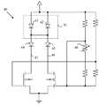
- FIG. 2is a schematic diagram of one embodiment of a light source according to the present invention.
- Light source 30includes a blue-emitting LED 31 and two red-emitting LEDs shown at 33 and 34 .
- the blue-emitting LEDis covered by a layer of phosphor in a manner analogous to that described above with reference to FIG. 1 .
- the LEDsare powered by a current source connected to lead 36 .
- the current ratio that traverses LED 31is split between LEDs 33 and 34 by a current control circuit 35 .
- the percentage of the current that goes through each LEDis adjusted in response to a temperature sensor 32 .
- LED 33is sized such that when all of the current flows through LED 33 at a predetermined ambient design temperature, the output of light source 30 has the correct color temperature. In this case, no current flows through LED 34 . Accordingly, LED 33 will be referred to as the primary LED in the following discussion. As the temperature rises, the efficiency with which LED 33 converts power to light decreases. This would result in the color temperature of light source 30 decreasing if no action were taken. The present invention is based on the observation that if some of the current is shifted to LED 34 , the power being dissipated in LED 33 will decrease, and hence, temperature of LED 33 will also decrease. As a result, the electrical conversion efficiency of LED 33 will increase. The light generated by LED 34 provides the light that is lost by running LED 33 at the lower current.
- the two LEDswere merely run such that half the current flowed through each LED all of the time, the light source would be too red.
- the electrical conversion efficiencydecreases with current under the operating conditions that are typically used to drive the red LEDs. If half of the current goes through each LED and the temperature remains at the ambient design temperature, the electrical conversion efficiency will be too high. Hence, the current is shifted to the second LED only as the temperature of LED 33 increases to make up for the loss in electrical conversion efficiency.
- LED 34is chosen such that the wavelength of the light generated by LED 34 is somewhat lower than that of the light generated by LED 33 .
- the average wavelength of the combination of LED 33 and LED 34is more nearly constant.
- the output wavelength of LED 34could be chosen such that when half of the current is flowing through LED 34 , the average wavelength of the light from LEDs 33 and 34 is the same as the average wavelength of the light from LED 33 when that LED is operating at the ambient design temperature.
- a red LED having a wavelength that is longer than that of the primary LEDcould be provided by sorting the LEDs from the manufacturing run and utilizing the LEDs wavelengths that are above the average for LED 34 .
- LED 31could be replaced by a plurality of blue-emitting LEDs connected in parallel, in series, or in a combination of parallel and series connections.
- LED 33could be replaced by a plurality of red-emitting LEDs connected in parallel, in series, or in a combination of parallel and series connections.
- the number of red-emitting LEDs that replace LED 33could be different than the number of blue LEDs that replace LED 31 .
- the number of LEDs that replace LED 34could be different than the number of LEDs used to replace LED 33 .
- Light source 40includes a blue light source 41 constructed from two blue LEDs 42 and 43 that are connected in parallel. The blue LEDs are covered by a phosphor layer such that light source 41 generates white light of a first color temperature.
- a primary red LED 44alters the color temperature to the desired design color temperature when light source 40 is at a predetermined first temperature.
- a thermal compensating red LED 45is utilized to correct for the loss in electrical conversion efficiency of LED 44 with increasing temperature.
- the temperature sensing functionis provided by thermistor 46 that sets the relative currents on paths 47 and 48 .
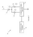
- Light source 50includes a primary light source 51 that has a decreasing electrical conversion efficiency with temperature and which is driven from a constant current source 53 .
- Light source 50also includes a compensating light source 52 that generates light in substantially the same output wavelength band as light source 51 .
- Light sources 51 and 52are connected to a current control circuit 54 that determines the fraction of the current from source 53 that traverses each light source.
- a temperature sensor 55senses the temperature of light 51 and causes current control circuit 54 to transfer current from light source 51 to light source 52 as the temperature increases to compensate for the reduction in electrical conversion efficiency in light source 51 . If the output spectrum of light source 51 also changes with increasing temperature, light source 52 can be selected such that light source 52 also compensates for the spectral shift by providing light at wavelengths that cause the average wavelength of the output of light source 50 to be more nearly the same as the average wavelength of the output of light source 51 at the lower temperature.
- the compensating LEDis only turned on in response to the temperature rising above the ambient temperature.
- embodiments in which some current flows through the compensating LED even at ambient temperaturecan also be advantageously utilized.
- the present inventionwill provide an improvement as long as the compensating LED current does not exceed the current in the primary LED at temperatures below the maximum operating temperature.
Landscapes
- Led Device Packages (AREA)
- Led Devices (AREA)
Abstract
Description
Claims (12)
Priority Applications (1)
| Application Number | Priority Date | Filing Date | Title |
|---|---|---|---|
| US12/896,615US8159153B2 (en) | 2010-10-01 | 2010-10-01 | LED light sources with improved thermal compensation |
Applications Claiming Priority (1)
| Application Number | Priority Date | Filing Date | Title |
|---|---|---|---|
| US12/896,615US8159153B2 (en) | 2010-10-01 | 2010-10-01 | LED light sources with improved thermal compensation |
Publications (2)
| Publication Number | Publication Date |
|---|---|
| US20110068715A1 US20110068715A1 (en) | 2011-03-24 |
| US8159153B2true US8159153B2 (en) | 2012-04-17 |
Family
ID=43756046
Family Applications (1)
| Application Number | Title | Priority Date | Filing Date |
|---|---|---|---|
| US12/896,615Expired - Fee RelatedUS8159153B2 (en) | 2010-10-01 | 2010-10-01 | LED light sources with improved thermal compensation |
Country Status (1)
| Country | Link |
|---|---|
| US (1) | US8159153B2 (en) |
Cited By (3)
| Publication number | Priority date | Publication date | Assignee | Title |
|---|---|---|---|---|
| US8944596B2 (en) | 2011-11-09 | 2015-02-03 | Welch Allyn, Inc. | Digital-based medical devices |
| US10078226B2 (en) | 2013-10-14 | 2018-09-18 | Welch Allyn, Inc. | Portable eye viewing device enabled for enhanced field of view |
| US11147441B2 (en) | 2018-01-16 | 2021-10-19 | Welch Allyn, Inc. | Physical assessment device |
Families Citing this family (8)
| Publication number | Priority date | Publication date | Assignee | Title |
|---|---|---|---|---|
| US9326346B2 (en) | 2009-01-13 | 2016-04-26 | Terralux, Inc. | Method and device for remote sensing and control of LED lights |
| US8358085B2 (en) | 2009-01-13 | 2013-01-22 | Terralux, Inc. | Method and device for remote sensing and control of LED lights |
| CA2781077A1 (en) | 2009-11-17 | 2012-06-28 | Terralux, Inc. | Led power-supply detection and control |
| CA2810026A1 (en) | 2010-09-16 | 2012-03-22 | Terralux, Inc. | Communication with lighting units over a power bus |
| DE102011085659A1 (en) | 2011-11-03 | 2013-05-08 | Tridonic Gmbh & Co. Kg | Clocked heating circuit for control gear for lamps |
| WO2013090904A1 (en) | 2011-12-16 | 2013-06-20 | Terralux, Inc. | System and methods of applying bleed circuits in led lamps |
| DE102012107796A1 (en)* | 2012-08-23 | 2014-03-27 | Osram Opto Semiconductors Gmbh | Light-emitting semiconductor component e.g. LED chip has semiconductor chip whose characteristic wavelength is smaller than another characteristic wavelength and forward voltage has greater temperature dependence than forward voltage |
| US9265119B2 (en) | 2013-06-17 | 2016-02-16 | Terralux, Inc. | Systems and methods for providing thermal fold-back to LED lights |
Citations (9)
| Publication number | Priority date | Publication date | Assignee | Title |
|---|---|---|---|---|
| US5803579A (en)* | 1996-06-13 | 1998-09-08 | Gentex Corporation | Illuminator assembly incorporating light emitting diodes |
| US20070278974A1 (en)* | 2006-05-31 | 2007-12-06 | Led Lighting Fixtures, Inc. | Lighting device with color control, and method of lighting |
| US20080191642A1 (en)* | 2005-04-08 | 2008-08-14 | Wart Hog Ii Holding B.V. | Methods and Apparatus for Operating Groups of High-Power Leds |
| US20090135866A1 (en)* | 2006-03-09 | 2009-05-28 | Kazuko Nishimura | Optical transmission circuit |
| US7557524B2 (en)* | 2000-12-20 | 2009-07-07 | Gestion Proche Inc. | Lighting device |
| US20100046221A1 (en)* | 2008-08-19 | 2010-02-25 | Jason Loomis Posselt | LED Source Adapted for Light Bulbs and the Like |
| US7796324B2 (en)* | 2006-10-10 | 2010-09-14 | Panasonic Corporation | Wavelength converting apparatus and image displaying apparatus |
| US20100270580A1 (en)* | 2009-04-22 | 2010-10-28 | Jason Loomis Posselt | Substrate based light source package with electrical leads |
| US20100277077A1 (en)* | 2009-05-04 | 2010-11-04 | Man Hay Pong | Apparatus and method to enhance the life of Light Emitting diode (LED) devices in an LED matrix |
- 2010
- 2010-10-01USUS12/896,615patent/US8159153B2/ennot_activeExpired - Fee Related
Patent Citations (9)
| Publication number | Priority date | Publication date | Assignee | Title |
|---|---|---|---|---|
| US5803579A (en)* | 1996-06-13 | 1998-09-08 | Gentex Corporation | Illuminator assembly incorporating light emitting diodes |
| US7557524B2 (en)* | 2000-12-20 | 2009-07-07 | Gestion Proche Inc. | Lighting device |
| US20080191642A1 (en)* | 2005-04-08 | 2008-08-14 | Wart Hog Ii Holding B.V. | Methods and Apparatus for Operating Groups of High-Power Leds |
| US20090135866A1 (en)* | 2006-03-09 | 2009-05-28 | Kazuko Nishimura | Optical transmission circuit |
| US20070278974A1 (en)* | 2006-05-31 | 2007-12-06 | Led Lighting Fixtures, Inc. | Lighting device with color control, and method of lighting |
| US7796324B2 (en)* | 2006-10-10 | 2010-09-14 | Panasonic Corporation | Wavelength converting apparatus and image displaying apparatus |
| US20100046221A1 (en)* | 2008-08-19 | 2010-02-25 | Jason Loomis Posselt | LED Source Adapted for Light Bulbs and the Like |
| US20100270580A1 (en)* | 2009-04-22 | 2010-10-28 | Jason Loomis Posselt | Substrate based light source package with electrical leads |
| US20100277077A1 (en)* | 2009-05-04 | 2010-11-04 | Man Hay Pong | Apparatus and method to enhance the life of Light Emitting diode (LED) devices in an LED matrix |
Cited By (7)
| Publication number | Priority date | Publication date | Assignee | Title |
|---|---|---|---|---|
| US8944596B2 (en) | 2011-11-09 | 2015-02-03 | Welch Allyn, Inc. | Digital-based medical devices |
| US9642517B2 (en) | 2011-11-09 | 2017-05-09 | Welch Allyn, Inc. | Digital-based medical devices |
| US10238462B2 (en) | 2011-11-09 | 2019-03-26 | Welch Allyn, Inc. | Digital-based medical devices |
| US11553981B2 (en) | 2011-11-09 | 2023-01-17 | Welch Allyn, Inc. | Digital-based medical devices |
| US10078226B2 (en) | 2013-10-14 | 2018-09-18 | Welch Allyn, Inc. | Portable eye viewing device enabled for enhanced field of view |
| US11147441B2 (en) | 2018-01-16 | 2021-10-19 | Welch Allyn, Inc. | Physical assessment device |
| USD959661S1 (en) | 2018-01-16 | 2022-08-02 | Welch Allyn, Inc. | Medical viewing device |
Also Published As
| Publication number | Publication date |
|---|---|
| US20110068715A1 (en) | 2011-03-24 |
Similar Documents
| Publication | Publication Date | Title |
|---|---|---|
| US8159153B2 (en) | LED light sources with improved thermal compensation | |
| US8395312B2 (en) | Phosphor converted light source having an additional LED to provide long wavelength light | |
| US7350933B2 (en) | Phosphor converted light source | |
| US8403531B2 (en) | Lighting device and method of lighting | |
| KR101507755B1 (en) | Light source comprising light-emitting clusters | |
| US9773776B2 (en) | Lighting module for emitting mixed light | |
| US10074781B2 (en) | Semiconductor light emitting devices including multiple red phosphors that exhibit good color rendering properties with increased brightness | |
| US9164001B2 (en) | Using an LED die to measure temperature inside silicone that encapsulates an LED array | |
| US20080297054A1 (en) | White Light Luminaire with Adjustable Correlated Colour Temperature | |
| KR20090082449A (en) | Light source comprising a light-excitable medium | |
| JPWO2011004796A1 (en) | Light emitting device | |
| US11230664B2 (en) | Dimmable light source | |
| US20120176047A1 (en) | Lighting Apparatus and Light Emitting Diode Device Thereof | |
| KR20100134779A (en) | Light emitting device | |
| RU2651794C2 (en) | Dimable light emitting arrangement | |
| US20130271974A1 (en) | Light-emitting diode module with a first component and a second component and method for the production thereof | |
| JP6481245B2 (en) | Light emitting device | |
| US9078331B2 (en) | Phosphor-converted white LED with low deviation of correlated color temperature and color coordinates and method of preparing the same | |
| US9599294B2 (en) | LED lighting device with mint, amber and yellow colored light-emitting diodes | |
| US11805579B2 (en) | Light fixture with at least one LED | |
| US9258867B2 (en) | Light emitting apparatus and method of operating thereof | |
| US20140001494A1 (en) | Light emitting diode | |
| TWI509845B (en) | Light source module | |
| US20140131749A1 (en) | Lighting apparatuses and driving methods regarding to light-emitting diodes | |
| WO2009138894A1 (en) | Light source having light-emitting clusters |
Legal Events
| Date | Code | Title | Description |
|---|---|---|---|
| AS | Assignment | Owner name:BRIDGELUX, INC., CALIFORNIA Free format text:ASSIGNMENT OF ASSIGNORS INTEREST;ASSIGNOR:HUM, DAVID;REEL/FRAME:025080/0945 Effective date:20100811 | |
| STCF | Information on status: patent grant | Free format text:PATENTED CASE | |
| AS | Assignment | Owner name:WHITE OAK GLOBAL ADVISORS, LLC, AS COLLATERAL AGEN Free format text:SECURITY AGREEMENT;ASSIGNOR:BRIDGELUX, INC.;REEL/FRAME:029281/0844 Effective date:20121109 | |
| AS | Assignment | Owner name:BRIDGELUX, INC., CALIFORNIA Free format text:TERMINATION AND RELEASE OF SECURITY INTEREST IN PATENT COLLATERAL RECORDED AT REEL/FRAME 029281/0844 ON NOVEMBER 12, 2012;ASSIGNOR:WELLS FARGO BANK, NATIONAL ASSOCIATION (SUCCESSOR BY ASSIGNMENT FROM WHITE OAK GLOBAL ADVISORS, LLC, AS COLLATERAL AGENT);REEL/FRAME:031560/0102 Effective date:20131029 | |
| FPAY | Fee payment | Year of fee payment:4 | |
| AS | Assignment | Owner name:XENIO CORPORATION, CALIFORNIA Free format text:ASSIGNMENT OF ASSIGNORS INTEREST;ASSIGNOR:BRIDGELUX, INC.;REEL/FRAME:038974/0307 Effective date:20160524 | |
| AS | Assignment | Owner name:XENIO SYSTEMS, INC., CALIFORNIA Free format text:CHANGE OF NAME;ASSIGNOR:XENIO CORPORATION;REEL/FRAME:044980/0188 Effective date:20170224 | |
| AS | Assignment | Owner name:PHILIPS LIGHTING HOLDING B.V., NETHERLANDS Free format text:ASSIGNMENT OF ASSIGNORS INTEREST;ASSIGNOR:XENIO SYSTEMS, INC.;REEL/FRAME:050288/0925 Effective date:20181231 | |
| MAFP | Maintenance fee payment | Free format text:PAYMENT OF MAINTENANCE FEE, 8TH YEAR, LARGE ENTITY (ORIGINAL EVENT CODE: M1552); ENTITY STATUS OF PATENT OWNER: LARGE ENTITY Year of fee payment:8 | |
| AS | Assignment | Owner name:SIGNIFY HOLDING B.V., NETHERLANDS Free format text:CHANGE OF NAME;ASSIGNOR:PHILIPS LIGHTING HOLDING B.V.;REEL/FRAME:050837/0576 Effective date:20190201 | |
| FEPP | Fee payment procedure | Free format text:MAINTENANCE FEE REMINDER MAILED (ORIGINAL EVENT CODE: REM.); ENTITY STATUS OF PATENT OWNER: LARGE ENTITY | |
| LAPS | Lapse for failure to pay maintenance fees | Free format text:PATENT EXPIRED FOR FAILURE TO PAY MAINTENANCE FEES (ORIGINAL EVENT CODE: EXP.); ENTITY STATUS OF PATENT OWNER: LARGE ENTITY | |
| STCH | Information on status: patent discontinuation | Free format text:PATENT EXPIRED DUE TO NONPAYMENT OF MAINTENANCE FEES UNDER 37 CFR 1.362 | |
| FP | Lapsed due to failure to pay maintenance fee | Effective date:20240417 |