US8159146B1 - Apparatus and method for pulsed L.E.D. illumination - Google Patents
Apparatus and method for pulsed L.E.D. illuminationDownload PDFInfo
- Publication number
- US8159146B1 US8159146B1US12/820,139US82013910AUS8159146B1US 8159146 B1US8159146 B1US 8159146B1US 82013910 AUS82013910 AUS 82013910AUS 8159146 B1US8159146 B1US 8159146B1
- Authority
- US
- United States
- Prior art keywords
- led
- light
- pulse
- leds
- voltage source
- Prior art date
- Legal status (The legal status is an assumption and is not a legal conclusion. Google has not performed a legal analysis and makes no representation as to the accuracy of the status listed.)
- Expired - Fee Related
Links
Images


Classifications
- F—MECHANICAL ENGINEERING; LIGHTING; HEATING; WEAPONS; BLASTING
- F21—LIGHTING
- F21L—LIGHTING DEVICES OR SYSTEMS THEREOF, BEING PORTABLE OR SPECIALLY ADAPTED FOR TRANSPORTATION
- F21L4/00—Electric lighting devices with self-contained electric batteries or cells
- F21L4/02—Electric lighting devices with self-contained electric batteries or cells characterised by the provision of two or more light sources
- F21L4/022—Pocket lamps
- F21L4/027—Pocket lamps the light sources being a LED
- H—ELECTRICITY
- H04—ELECTRIC COMMUNICATION TECHNIQUE
- H04N—PICTORIAL COMMUNICATION, e.g. TELEVISION
- H04N23/00—Cameras or camera modules comprising electronic image sensors; Control thereof
- H04N23/50—Constructional details
- H04N23/51—Housings
- H—ELECTRICITY
- H04—ELECTRIC COMMUNICATION TECHNIQUE
- H04N—PICTORIAL COMMUNICATION, e.g. TELEVISION
- H04N23/00—Cameras or camera modules comprising electronic image sensors; Control thereof
- H04N23/56—Cameras or camera modules comprising electronic image sensors; Control thereof provided with illuminating means
- H—ELECTRICITY
- H04—ELECTRIC COMMUNICATION TECHNIQUE
- H04N—PICTORIAL COMMUNICATION, e.g. TELEVISION
- H04N23/00—Cameras or camera modules comprising electronic image sensors; Control thereof
- H04N23/70—Circuitry for compensating brightness variation in the scene
- H04N23/74—Circuitry for compensating brightness variation in the scene by influencing the scene brightness using illuminating means
- H—ELECTRICITY
- H05—ELECTRIC TECHNIQUES NOT OTHERWISE PROVIDED FOR
- H05B—ELECTRIC HEATING; ELECTRIC LIGHT SOURCES NOT OTHERWISE PROVIDED FOR; CIRCUIT ARRANGEMENTS FOR ELECTRIC LIGHT SOURCES, IN GENERAL
- H05B45/00—Circuit arrangements for operating light-emitting diodes [LED]
- H05B45/10—Controlling the intensity of the light
- H—ELECTRICITY
- H05—ELECTRIC TECHNIQUES NOT OTHERWISE PROVIDED FOR
- H05B—ELECTRIC HEATING; ELECTRIC LIGHT SOURCES NOT OTHERWISE PROVIDED FOR; CIRCUIT ARRANGEMENTS FOR ELECTRIC LIGHT SOURCES, IN GENERAL
- H05B45/00—Circuit arrangements for operating light-emitting diodes [LED]
- H05B45/20—Controlling the colour of the light
- H05B45/22—Controlling the colour of the light using optical feedback
- H—ELECTRICITY
- H05—ELECTRIC TECHNIQUES NOT OTHERWISE PROVIDED FOR
- H05B—ELECTRIC HEATING; ELECTRIC LIGHT SOURCES NOT OTHERWISE PROVIDED FOR; CIRCUIT ARRANGEMENTS FOR ELECTRIC LIGHT SOURCES, IN GENERAL
- H05B47/00—Circuit arrangements for operating light sources in general, i.e. where the type of light source is not relevant
- H05B47/10—Controlling the light source
- F—MECHANICAL ENGINEERING; LIGHTING; HEATING; WEAPONS; BLASTING
- F21—LIGHTING
- F21Y—INDEXING SCHEME ASSOCIATED WITH SUBCLASSES F21K, F21L, F21S and F21V, RELATING TO THE FORM OR THE KIND OF THE LIGHT SOURCES OR OF THE COLOUR OF THE LIGHT EMITTED
- F21Y2101/00—Point-like light sources
- F—MECHANICAL ENGINEERING; LIGHTING; HEATING; WEAPONS; BLASTING
- F21—LIGHTING
- F21Y—INDEXING SCHEME ASSOCIATED WITH SUBCLASSES F21K, F21L, F21S and F21V, RELATING TO THE FORM OR THE KIND OF THE LIGHT SOURCES OR OF THE COLOUR OF THE LIGHT EMITTED
- F21Y2115/00—Light-generating elements of semiconductor light sources
- F21Y2115/10—Light-emitting diodes [LED]
- H—ELECTRICITY
- H05—ELECTRIC TECHNIQUES NOT OTHERWISE PROVIDED FOR
- H05B—ELECTRIC HEATING; ELECTRIC LIGHT SOURCES NOT OTHERWISE PROVIDED FOR; CIRCUIT ARRANGEMENTS FOR ELECTRIC LIGHT SOURCES, IN GENERAL
- H05B45/00—Circuit arrangements for operating light-emitting diodes [LED]
- H05B45/10—Controlling the intensity of the light
- H05B45/12—Controlling the intensity of the light using optical feedback
- H—ELECTRICITY
- H05—ELECTRIC TECHNIQUES NOT OTHERWISE PROVIDED FOR
- H05B—ELECTRIC HEATING; ELECTRIC LIGHT SOURCES NOT OTHERWISE PROVIDED FOR; CIRCUIT ARRANGEMENTS FOR ELECTRIC LIGHT SOURCES, IN GENERAL
- H05B45/00—Circuit arrangements for operating light-emitting diodes [LED]
- H05B45/30—Driver circuits
- H05B45/32—Pulse-control circuits
- H—ELECTRICITY
- H05—ELECTRIC TECHNIQUES NOT OTHERWISE PROVIDED FOR
- H05B—ELECTRIC HEATING; ELECTRIC LIGHT SOURCES NOT OTHERWISE PROVIDED FOR; CIRCUIT ARRANGEMENTS FOR ELECTRIC LIGHT SOURCES, IN GENERAL
- H05B45/00—Circuit arrangements for operating light-emitting diodes [LED]
- H05B45/30—Driver circuits
- H05B45/395—Linear regulators
- H05B45/397—Current mirror circuits
- Y—GENERAL TAGGING OF NEW TECHNOLOGICAL DEVELOPMENTS; GENERAL TAGGING OF CROSS-SECTIONAL TECHNOLOGIES SPANNING OVER SEVERAL SECTIONS OF THE IPC; TECHNICAL SUBJECTS COVERED BY FORMER USPC CROSS-REFERENCE ART COLLECTIONS [XRACs] AND DIGESTS
- Y02—TECHNOLOGIES OR APPLICATIONS FOR MITIGATION OR ADAPTATION AGAINST CLIMATE CHANGE
- Y02B—CLIMATE CHANGE MITIGATION TECHNOLOGIES RELATED TO BUILDINGS, e.g. HOUSING, HOUSE APPLIANCES OR RELATED END-USER APPLICATIONS
- Y02B20/00—Energy efficient lighting technologies, e.g. halogen lamps or gas discharge lamps
- Y02B20/30—Semiconductor lamps, e.g. solid state lamps [SSL] light emitting diodes [LED] or organic LED [OLED]
- Y—GENERAL TAGGING OF NEW TECHNOLOGICAL DEVELOPMENTS; GENERAL TAGGING OF CROSS-SECTIONAL TECHNOLOGIES SPANNING OVER SEVERAL SECTIONS OF THE IPC; TECHNICAL SUBJECTS COVERED BY FORMER USPC CROSS-REFERENCE ART COLLECTIONS [XRACs] AND DIGESTS
- Y10—TECHNICAL SUBJECTS COVERED BY FORMER USPC
- Y10S—TECHNICAL SUBJECTS COVERED BY FORMER USPC CROSS-REFERENCE ART COLLECTIONS [XRACs] AND DIGESTS
- Y10S362/00—Illumination
- Y10S362/80—Light emitting diode
- Y—GENERAL TAGGING OF NEW TECHNOLOGICAL DEVELOPMENTS; GENERAL TAGGING OF CROSS-SECTIONAL TECHNOLOGIES SPANNING OVER SEVERAL SECTIONS OF THE IPC; TECHNICAL SUBJECTS COVERED BY FORMER USPC CROSS-REFERENCE ART COLLECTIONS [XRACs] AND DIGESTS
- Y10—TECHNICAL SUBJECTS COVERED BY FORMER USPC
- Y10S—TECHNICAL SUBJECTS COVERED BY FORMER USPC CROSS-REFERENCE ART COLLECTIONS [XRACs] AND DIGESTS
- Y10S362/00—Illumination
- Y10S362/802—Position or condition responsive switch
Definitions
- This inventionrelates to the field of lighting, and more specifically to a method and apparatus of controlling and powering a solid-state light source such as a light-emitting diode or LED, for a portable battery-powered flashlight.
- a solid-state light sourcesuch as a light-emitting diode or LED
- One common flashlightincludes a two-cell battery for power, an incandescent lamp to emit light, and a simple single-pole switch to connect and disconnect the battery to the lamp.
- Other flashlightsuse other numbers of battery cells in order to provide a voltage suitable for various particular conditions.
- Lanternsoften use a fluorescent tube to emit light.
- Certain keychain fobsuse a pair of hearing-aid cells and a red-light light-emitting diode (LED) in order to provide short-range lighting such as might be needed to find a keyhole in the dark.
- LEDred-light light-emitting diode
- Battery technologyis such that as electrical power is withdrawn from a battery cell, the voltage available across a given current load will decrease. This decreased available voltage across the given load causes reduced light output, gradually dimming the light as the battery charge depletes.
- LEDshave voltage, current, and power parameters that must be controlled in order to maximize device life.
- a current-limiting resistoris placed in series with an LED in order that only a portion of the voltage drop from the battery is across the LED and the rest of the voltage drop is across the resistor. This voltage drop and corresponding power loss in the resistor is dissipated as waste heat, which is inefficient for a flashlight which should be designed to emit light.
- Some embodimentsprovide a method of providing changeable illumination of such compact size and low weight as to be suitable for single-handed portable operation by a user.
- the methodincludes providing one or more LEDs having a first characteristic color spectrum output and one or more LEDs having a second characteristic color spectrum output, wherein the first characteristic color spectrum output is different from the second characteristic color spectrum output, selectively applying pulsed power from a DC voltage source to the LEDs, wherein the pulses are of high-enough frequency such that the human eye does not perceive the pulses, and changing a pulse characteristic of the pulsed power in order to change a proportion of light output having the first characteristic color spectrum output to that having the second characteristic color spectrum output.
- Some embodimentsprovide a portable pulsed LED illumination source of such compact size and low weight as to be suitable for single-handed portable operation by a user.
- the sourceinclude one or more LEDs having a first characteristic color spectrum output, one or more LEDs having a second characteristic color spectrum output, wherein the first characteristic color spectrum output different from the second characteristic color spectrum output, and a control circuit that controls a pulse characteristic to the one or more LEDs having a first characteristic color spectrum output in order to change a proportion of light output having the first characteristic color spectrum output to that having the second characteristic color spectrum output.
- the present inventionprovides a method and apparatus for an L.E.D. flashlight or other LED illumination source.
- a flashlightis described.
- the flashlightincludes a flashlight housing suitable for receiving therein and/or mounting thereon at least one DC voltage source such as a battery.
- the flashlightalso includes a light-emitting diode (LED) housing connected to the flashlight housing, the LED housing including a first plurality of LED units that each emit light and have a reflector for collimating the emitted light forwardly therefrom generally along an LED optical axis, the first plurality of LED units including at least seven individual LED units.
- LEDlight-emitting diode
- the flashlightalso includes a first electrical circuit that selectively applies power from the DC voltage source to the LED units, wherein the flashlight is of such compact size and low weight as to be suitable for single handed portable operation by a user, the flashlight further having a purpose of providing general-purpose illumination.
- the LED optical axes of the first plurality of LED units in the flashlightare substantially parallel to one another.
- the flashlightfurther includes a second plurality of LED units that each emit light and have a reflector for collimating the emitted light forwardly therefrom generally along an LED optical axis, wherein the LED optical axes of the second plurality of LED units converge or diverge from one another forwardly from the housing.
- an optical spread angle of the first plurality of LED units in the flashlightare substantially equal to one another.
- the flashlightfurther includes a second plurality of LED units that each emit light and have a reflector for collimating the emitted light forwardly therefrom generally along an LED optical axis, wherein an optical spread angle of the second plurality of LED units are substantially equal to one another, and different than the optical spread angle of the first plurality of LED units.
- the LED unitsare connected in a parallel-series configuration with at least two LED units coupled in parallel to one another and in series with at least one other LED unit, and the DC voltage source includes at least three battery cells connected in series.
- the first electrical circuitfurther includes a control circuit for maintaining a predetermined light output level of the LED units as a charge on the battery cell varies.
- the control circuitmaintains an average predetermined light output level of the LED units as the charge on the battery cell varies by increasing a pulse width or a pulse frequency as the charge on the battery cell decreases.
- the control circuitmaintains an average predetermined light output level of the LED units by measuring a battery voltage and adjusting a pulse width or a pulse frequency or both to maintain the average light output at the predetermined level.
- the control circuitmaintains an average predetermined light output level of the LED units by measuring an average light output and adjusting a pulse width or a pulse frequency or both to maintain the measured average light output at the predetermined level.
- a flashlightincluding: (a) a flashlight housing, the housing being suitable for at least one of receiving therein and mounting thereon at least one DC voltage source that includes at least one battery cell; (b) a light-emitting diode (LED) housing connected to the flashlight housing, the LED housing including one or more first LED units that each emit light and have a reflector for collimating the emitted light forwardly therefrom generally along an LED optical axis; and (c) a first electrical circuit that selectively applies power from the DC voltage source to the LED units, the first electrical circuit further including a control circuit for maintaining a predetermined light output level of the LED units as a charge on the battery cell varies; wherein the flashlight is of such compact size and low weight as to be suitable for single handed portable operation by a user, the flashlight further having a purpose of providing general-purpose illumination.
- a flashlight housingbeing suitable for at least one of receiving therein and mounting thereon at least one DC voltage source that includes at least one battery cell
- the first LED unitsbeing a first plurality of LED units, wherein the LED optical axes of the first plurality of LED units are substantially parallel to one another.
- the flashlightfurther includes a second plurality of LED units that each emit light and have a reflector for collimating the emitted light forwardly therefrom generally along an LED optical axis, wherein the LED optical axes of the second plurality of LED units converge or diverge from one another forwardly from the housing.
- the first LED unitsare a first plurality of LED units, wherein an optical spread angle of the first plurality of LED units are substantially equal to one another.
- the flashlightfurther includes a second plurality of LED units that each emit light and have a reflector for collimating the emitted light forwardly therefrom generally along an LED optical axis, wherein an optical spread angle of the second plurality of LED units are substantially equal to one another, and different than the optical spread angle of the first plurality of LED units.
- Another aspect of the present inventionprovides a method of providing general-purpose illumination of such compact size and low weight as to be suitable for single handed portable operation by a user, including the steps of: (a) providing one or more first LED units that each emit light and have a reflector for collimating the emitted light forwardly therefrom generally along an LED optical axis; (b) selectively applying power from a DC voltage source to the LED units; and (c) maintaining a predetermined light output level of the LED units as a charge on the battery cell varies by controlling the step (b).
- the step of maintainingmaintains an average predetermined light output level of the LED units as the charge on the battery cell varies by increasing a pulse energy or a pulse frequency as the charge on the battery cell decreases. In another embodiment, the step of maintaining maintains an average predetermined light output level of the LED units by measuring a battery voltage and adjusting a pulse width or a pulse frequency or both to maintain the average light output at the predetermined level. In still another embodiment, the step of maintaining maintains an average predetermined light output level of the LED units by measuring a light output and adjusting a pulse energy or a pulse frequency or both to maintain an average light output at the predetermined level.
- an illumination sourcethat includes (a) a light-emitting diode (LED) housing including one or more LEDs; and (b) a control circuit that selectively applies power from a source of electric power to the LEDs, the control circuit substantially maintaining a light output characteristic of the LEDs as a voltage of the voltage source varies over a range that would otherwise vary the light output characteristic.
- the light output characteristic that is maintainedis light output intensity.
- the control circuitmaintains the light output intensity of the LED units as the voltage of the DC voltage source varies by increasing a pulse width, a pulse energy, or a pulse frequency as the voltage of the DC voltage source decreases.
- control circuitmaintains an average predetermined light output level of the LED units by measuring a voltage and adjusting a pulse energy or a pulse frequency or both to maintain the average light output at the predetermined level. In yet another such embodiment, the control circuit maintains an average predetermined light output level of the LED units by measuring an average light output and adjusting a pulse width or a pulse frequency or both to maintain the measured average light output at the predetermined level.
- a battery-powered portable flashlightincluding: a casing ( 110 ) suitable to hold a battery; one or more light-emitting devices (LEDs) ( 150 ) mounted to the casing; a switch ( 140 ) mounted to the casing; and a control circuit ( 130 ) coupled to the battery, the LEDs, and the switch, wherein the control circuit drives the LEDs with electrical pulses at a frequency high enough that light produced by the LEDs has an appearance to a human user of being continuous rather than pulsed, and wherein the LEDs have proportion of on-time that increases as remaining battery power decreases.
- a battery-powered portable flashlight100 including: a casing ( 110 ) suitable to hold a battery; one or more light-emitting devices (LEDs) ( 150 ) mounted to the casing; a switch ( 140 ) mounted to the casing; and a control circuit ( 130 ) coupled to the battery, the LEDs, and the switch, wherein the control circuit drives the LEDs with electrical pulses at a frequency high enough that light produced by the
- One such embodimentfurther includes a feedback circuit that controls the pulses so that light intensity produced by the LEDs, as perceived by the human user, is substantially constant across a greater range of battery power or voltage than a corresponding range for which light intensity is equally constant without the feedback circuit.
- the feedback circuitmeasures a light output of the LEDs.
- Another such embodimentfurther includes a battery-voltage-measuring circuit coupled to the control circuit.
- Yet another aspect of the present inventionprovides a method for driving battery-powered portable flashlight ( 100 ) having a casing ( 110 ), a DC power source mounted to the casing, one or more solid-state light-emitting device (LEDs) ( 150 ) mounted to the casing, the method including the steps of: receiving input from a user; and based on the received input, generating a series of pulses to drive the LEDs such that the LEDs have proportion of on-time that increases as remaining battery power decreases.
- a method for driving battery-powered portable flashlight ( 100 )having a casing ( 110 ), a DC power source mounted to the casing, one or more solid-state light-emitting device (LEDs) ( 150 ) mounted to the casing, the method including the steps of: receiving input from a user; and based on the received input, generating a series of pulses to drive the LEDs such that the LEDs have proportion of on-time that increases as remaining battery power decreases.
- LEDssolid-state light-emitting device
- Still another aspect of the present inventionprovides an illumination source including (a) a light-emitting diode (LED) housing including one or more LEDs; and (b) a control circuit that selectively applies power from a source of electric power to the one or more LEDs, the control circuit maintaining a predetermined light output color spectrum of the one or more LEDs as a voltage of the source of electric power varies.
- the one or more LEDscomprise one or more LEDs having a first characteristic color spectrum output and one or more LEDs having a second characteristic color spectrum output, the first characteristic color spectrum output different from the second characteristic color spectrum output, and the control circuit controls a pulse characteristic in order to control the proportion of light output having the first characteristic color spectrum output to that having the second characteristic color spectrum output.
- the one or more LEDscomprise one or more LEDs having a characteristic color spectrum output that varies based on applied current, and the control circuit controls a pulse current in order to control the characteristic color spectrum output.
- an illumination sourcethat includes (a) a light-emitting diode (LED) housing including one or more LEDs; and (b) a control circuit that selectively applies power from a source of electric power to the LEDs to adjust a light output color spectrum of the one or more LEDs.
- LEDlight-emitting diode
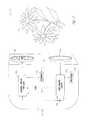
- FIG. 1shows one embodiment of the present invention, a schematic representation of a handheld LED flashlight 100 .
- FIG. 2is a circuit block diagram of an LED flashlight circuit 200 , which circuit is used in some embodiments of LED flashlight 100 of FIG. 1 or LED light source in camcorder 500 of FIG. 5 or other devices such as machine-vision systems.
- FIG. 3a circuit block diagram of an LED flashlight circuit 300 , which circuit is used in some embodiments of LED flashlight 100 of FIG. 1 or LED light source in camcorder 500 of FIG. 5 or other devices such as machine-vision systems.
- FIG. 4a circuit block diagram of an LED flashlight circuit 400 , which circuit is used in some embodiments of LED flashlight 100 of FIG. 1 or LED light source in camcorder 500 of FIG. 5 or other devices such as machine-vision systems.
- FIG. 5is a diagram showing a controlled LED light source is integrated into a handheld camcorder 500 .
- FIG. 6is a graph of color spectrum versus current for an LED to be used in one embodiment of the present invention.
- FIG. 7is circuit block diagram of an LED illumination device circuit 700 , which circuit is used in some embodiments of LED flashlight 100 of FIG. 1 or LED light source in camcorder 500 of FIG. 5 or other devices such as machine-vision systems.
- FIG. 8is circuit block diagram of an LED illumination device circuit 700 that uses a current mirror.
- FIG. 9is a graph of color spectrum (photoluminescence) versus temperature for an LED to be used in one embodiment of the present invention.
- FIG. 10is circuit block diagram of a machine vision system using an LED illumination device according to the present invention.
- FIG. 11is circuit block diagram of an LED illumination device according to the present invention.
- the present inventiontakes advantage of the efficiency of high-intensity, light-emitting diodes (LEDs) in the visible spectrum and/or infra-red (IR) or ultra-violet (UV), arranged in various patterns, the low-voltage properties of CMOS integrated circuits and components, and the efficiency derived from switching the current to and limiting the duration of current to the LEDs to project light efficiently and with constant brightness even as the battery supply voltage decays over time.
- the inventiontakes advantage of the dynamic impedance of the LEDs which causes the voltage across the LED to rise rapidly relative to the current flow through the LED to limit the initial current flow to the LED, when battery voltage is highest, to prevent wire bond heating from causing premature failure of the LEDs.
- the present inventioncontrols the current flow duration (pulse width) to limit power dissipation in the LEDs during the LEDs' on state, and increasing the pulse width as the battery voltage decreases over time to maintain substantially constant perceived or average LED intensity over the course of the battery's life.
- the inventioncontrols the switching frequency of the pulse width to further control the LED intensity and power dissipation while maintaining a constant light output from the LEDs as perceived or visible to the human eye, or a light-sensing device, e.g., camera, night-vision scope, CMOS and CCD sensor and pixel arrays.
- the present inventionprovides a compact, portable light source, preferably sized to be readily hand-held, for illuminating an object, several objects, or areas for human use and/or machine operation.
- the inventionmeasures battery voltage and in turn regulates the LED intensity.
- the present inventionuses a light-sensing device such as a light-sensing transistor or light-detecting diode (LDD) in proximity to the output LED(s) to measure the average brightness and further regulate the LEDs' output.
- a light-sensing devicesuch as a light-sensing transistor or light-detecting diode (LDD) in proximity to the output LED(s) to measure the average brightness and further regulate the LEDs' output.
- LDDlight-detecting diode
- Another embodiment of the present inventionprovides operator-selectable control of the pulse frequency and/or the pulse width to provide a reduced apparent brightness in order to increase battery life in situations when maximum brightness is not required.
- the apparent (visible) pulse frequencywould provide a stroboscope effect for safety or entertainment.
- the visibly interrupted or pulsed pulse trainmay include repetitive pulses or a coded sequence as in Morse code “SOS” or a predetermined password or security string of pulses that may then be used as a key or identifier.
- SOSMorse code
- a further refinement of this embodimentwould provide the user with a method for strobing out a message.
- a single visible pulsemay actually include a high-frequency series of pulses in order to increase the apparent brightness of a single pulse while also protecting the LEDs from excessive power dissipation.
- a variable or adjustable constant sequence pulse trainis established for the accurate measurement of the velocity or frequency of an object in motion or vibration.
- LEDsfor specialized purposes.
- long-wavelength LEDs660 nm or longer, are used to provide underwater divers or aquarium enthusiasts a light source for observing undersea life at night without adversely affecting the nocturnal activities of such wildlife. This functionality is also useful for tropical aquarium owners who also wish to observe the nocturnal activities of the occupants of their aquariums.
- short-wavelength blue LEDsare used with a UV filter to view fluorescing materials, including but not limited to: taggants, stamps, security codes and security seals. As UV LEDs become readily available (such as those announced as made by IBM Corporation in the Mar.
- a suitable LED normally emitting in the blue spectrumfor example made from GaN (gallium nitride) or InGaN (indium gallium nitride), is pulsed by pulses of sufficiently high current to blue-shift the output and sufficiently short duration to not destroy the LED in order to maintain a constant light intensity while shifting the color spectrum from blue to ultraviolet.
- IR LEDsfor military or police use to enhance the usefulness of night-vision equipment and for friend-or-foe identification, multiple color LEDs to produce a white light source, and combinations of colored LEDs to enhance the ability of color-blind individuals to perceive colors.
- Other usesinclude LEDs chosen for use in photographic darkrooms wherein the LED wavelength is chosen to prevent undesired exposure of light-sensitive materials.
- Another embodiment of the present inventionuses LEDs of various “viewing” angles to achieve wide-angle viewing versus narrow-angle, long-range viewing and combinations thereof.
- a further refinement of this embodimentutilizes a Fresnel lens (or other lens or reflector arrangement) to provide a focusable light source.
- Another embodimentuses polarizers to reduce specular reflections for enhanced viewing or for use in machine-vision applications.
- Another embodimentutilizes quickly and easily pluggable/replaceable LED arrays or heads of various shapes, colors, and/or viewing angles for different applications.
- the light outputis momentarily interrupted repetitively, or strobed, to indicate low battery condition with some estimation of time to battery failure, e.g., the number of pulses could indicate the estimated number of minutes of battery time. As the estimation of time to battery failure changes, the repetition rate is varied to indicate impending battery failure. It is understood that this operational mode is easily distinguished from other operational modes by the duration of on time versus off time. In strobe mode, low battery condition is indicated by dropping pulses; e.g., every fourth output pulse is dropped, or three of four pulses is dropped creating an easily distinguishable variance in visible output of the invention.
- a switchis utilized to control the functions (and/or brightness) of the invention.
- a variance of this embodimentuses a thumb-wheel, or rotary switch to vary the switching characteristics to produce a variable light output.
- a programmable microprocessoris utilized to provide control functionality.
- FIG. 1shows one embodiment of the present invention (a schematic representation of a LED flashlight 100 ) having a case 110 , a battery 120 or other portable DC power supply, a power supply and control circuit 130 , a switch circuit 140 , a plurality of LEDs 150 , and optionally a feedback circuit 160 .
- feedback circuit 160controls pulse width and/or frequency as a function of parameters such as battery voltage, LED light output intensity, power dissipation or device temperature, or LED color spectrum output.
- Case 110is any convenient size and shape, and is typically designed to hold the battery, provide a suitable grip to be handheld, and provide a housing for the circuitry and LEDs.
- battery 120includes one or more cells which can be any suitable technology such as alkaline dry cells or rechargeable cells. Alternatively, other portable DC electrical power sources can be used as desired in place of battery 120 .
- Power supply and control circuit (PSCC) 130responds to switch circuit to apply electrical power from battery 120 to LEDs 150 , controlled in order to prevent overloading and premature destruction of LEDs 150 while minimizing power dissipation within PSCC 130 , thus maximizing battery life, providing the desired accuracy or level of the amount of light emitted at different battery voltages or other environmental conditions that would otherwise vary the light output.
- PSCCPower supply and control circuit
- Switch circuit 140allows the user to control various flashlight functions such as, for example, on/off, setting light level, setting light color, setting pulse or strobe frequency, and checking battery voltage or remaining power.
- PSCC 130provides a pulse train, in which pulse frequency, pulse width, or pulse shape/height, and/or the number of LEDs that are driven, is controlled in order to provide a relatively constant light output level even as battery voltage declines and power is drained.
- feedback 160measures the light output of LEDs 150 (e.g., using a photo diode or other suitable light detecting device) and provides a signal that allows PSCC 130 to adjust the light output to a desired level (typically providing a constant light output even as battery voltage declines as power is drained).
- the width of each pulseis adjusted to keep a constant average light output (widening each pulse as the intensity of light decreases, in order to obtain a constant light output).
- flashlight 100is used in conjunction with a portable video camcorder or other video camera, and feedback 160 measures the overall ambient light and provides a signal that allows generation of flashlight pulses to compensate for lack of light, in order to provide optimal lighting for the video camera.
- the pulses to the LEDsare synchronized to the video camera frame rate using optional pulse synchronization (sync) signal 170 in order that the light pulse from LEDs 150 is only on when the video camera shutter is collecting light (avoiding light output when the camera will not benefit from it).
- feedback 160measures battery voltage, and increases pulse width, frequency, or height as battery voltage or power declines. In yet another embodiment, feedback 160 measures the current going through LEDs 150 , and makes the appropriate adjustment to pulse width or frequency in order to maintain constant or desired light output.
- FIG. 2is a schematic of one embodiment of a circuit used for flashlight 100 .
- momentary contact switch 146is momentarily closed by a user to activate light output.
- Power-switch circuit 132in one embodiment, a TK114 circuit by Toko America available from Digikey Corporation of Thief River Falls, Minn.
- Voutvoltage to Vout, which is applied through resistor divider 138 - 138 to transistor 136 .
- circuit 132is replaced by a simple slide switch as is used in conventional flashlights, and which, when closed, connects Vin to Vout (eliminating the need for resistors 137 , 138 , and 139 , switch 146 , and transistor 136 ). Transistor 136 and resistor 137 then maintain the control voltage low enough to keep power circuit 132 turned on even after switch 146 is released by the user to its open position (transistor 136 is “on” as long as circuit 132 is on and applying battery voltage to Vout).
- microprocessor 134is any suitable microprocessor, such as a PIC16C62X microcontroller by Microchip and available from Digikey Corp. of Thief River Falls, Minn., 56701.
- the PIC16C62Xincludes two analog comparators with a programmable on-chip voltage reference, a timer, and 13 input/output (I/O) pins each capable of direct LED driving of 25 mA source or sink.
- MP 134is programmed to receive a feedback signal 260 from feedback circuit 160 , and on the basis of the feedback signal, adjust the drive signal(s) 250 to LEDs 150 , thus adjusting the light output.
- a lookup table 234is used to convert a digital value derived from feedback signal 260 into a digital value used to control drive signal 250 .
- optional feature switches 142are provided to control various parameters of light output such as, for example, intensity, color, duration (i.e., time until automatic power down), frequency (i.e., a strobe control), etc.
- an external pulse sync signal 170is provided, isolated though a standard opto-isolator circuit 171 , and provided as an input to pulse sync input pin 270 of MP 134 .
- pulse sync signal 170is driven from a video camera (such as a camcorder or a machine-vision video camera), in order to synchronize light output with the light gathering/shutter open times of the camera.
- pulse sync signal 170is driven from a spark-plug-wire pickup in order to provide a timing strobe of light pulses for tuning an internal combustion engine.
- feature switches 142include momentary contact switches in pairs, one switch of the pair used to increase a particular parameter, and the other switch of the pair used to decrease the particular parameter (such as is done commonly in television remote control devices).
- a pair of switchesincreases/decreases overall light output intensity.
- coloris adjusted, e.g., using one pair of buttons for blue LED output, another pair for green LED output, and a third pair for red LED output; or using one pair to control the X-coordinate and another pair to control the Y-coordinate of chromaticity (such as a CIE chromaticity diagram's X and Y coordinates).
- a pair of switch buttonsincreases/decreases the remaining timeout value.
- the number of LEDs that are “on”are varied to provide a visual indication to the user of the value of that parameter, for example the timeout value could be varied from one to ten minutes until power off, and as the button to increase that parameter is held down, the timeout parameter is increased successively from one to ten, and a corresponding number of LEDs (one to ten) are turned on to provide this visual indication.
- audible indications of such parametersare provided, e.g., by providing variable pitch or numbers of clicks to give the user feedback as to the value of the parameters being adjusted or measured.
- a primary feature of some embodiments of the present inventionis to provide a large number of individual LEDs in order to provide sufficient generalized and/or focused illumination to be useful as a handheld flashlight, or in particular, as an illumination source for a scene or object to be imaged by a video camera (e.g., in a camcorder or machine-vision system).
- a video camerae.g., in a camcorder or machine-vision system.
- high intensity LEDshaving a luminous intensity of, say 2 cd, twenty to fifty LEDs are typically needed to provide a good flashlight, although in some applications as few as seven LEDs provide desirable results.
- each individual LEDis separately packaged in a transparent encapsulant (e.g., a T 13 ⁇ 4 package) that provides manufacturing efficiencies and provides better heat dissipation by spreading the active light emitting chips apart from one another.
- a transparent encapsulante.g., a T 13 ⁇ 4 package
- white LEDsare used (such as white LEDs that utilize a blue LED chip and a YAG phosphor that converts a portion of the blue light to yellow, thus yielding a white-appearing light output, such as part number NSPW 310AS available from Nichia Chemical Industries Ltd. of Japan and Nichia America Corp., 3775 Hempland Road, Mountville Pa., 17554).
- standard high-efficiency colored LEDs of red, yellow, green, and/or blueare used to provide light of the desired intensity and color.
- LEDs of each colorare controlled separately in order to provide the desired overall hue or whiteness of the combined light output.
- feedback circuit 160measures the video output signal from the camera and provides a feedback signal 260 that allows adjustment of the light output of LEDs 150 in order to optimize the video signal.
- the controlled LED light sourceis integrated into a handheld camcorder 500 .
- the video camera circuitalso provides pulse sync signal 170 in order to synchronize the light output to the video light gathering time windows.
- feedback circuit 160measures the color balance of the video output signal, and provides separate feedback intensity control for each of a plurality of (e.g., two or three) separate groups of color LEDs, for example, red, green, and blue.
- green LEDssuch as part number NSPG 500S and blue LEDs such as part number NSPB 500S, both available from Nichia Chemical Industries Ltd. of Japan and Nichia America Corp., 3775 Hempland Road, Mountville Pa., 17554 are used, and red LEDs such as part number HLMP-C115 available from Hewlett Packard Company.
- FIG. 3a circuit block diagram of an LED flashlight circuit 300 , which circuit is used in some embodiments of LED flashlight 100 of FIG. 1 or LED light source in video camera 500 of FIG. 5 .
- Circuit 331replaces circuit 132 and 134 of FIG. 2 using similar circuit concepts (however, in one embodiment, the entire circuitry of circuit 331 is integrated onto a single integrated circuit chip).
- switch 146When switch 146 is momentarily closed, circuit 331 draws output pin 332 low, turning on PNP transistor 133 , which remains turned on until circuit 331 again detects that switch 146 is momentarily closed, at which time pin 332 is allowed to float high, turning off the flashlight circuit 300 .
- One or more output pins 336drive one or more low-threshold high-power MOSFETs 350 (e.g., a plurality of MOSFETs 350 are used to drive groups of LEDs of different colors, as described above).
- pin 336provides a variable pulse control signal to vary pulse width, pulse frequency, or both in order to control light output as described above.
- output pin 333is driven low to turn on LED 152 , and in one such embodiment, pulses LED 152 in a manner that the pulses are perceptible to the human eye, and varying the pulse pattern or timing in order to indicate the estimated remaining battery power.
- LED 152is repeated pulsed in this manner, e.g., ten pulses spaced at 1 ⁇ 3 second, then a 3 second period of time when LED 152 is off, ten pulses spaced at 1 ⁇ 3 second, then a 3 second period of time when LED 152 is off, in a repeating pattern as long as the flashlight is on.
- thisprovides the user with the only indication of remaining battery life, since LEDs 151 are driven to provide constant illumination, regardless of battery voltage variations or other factors that would otherwise vary light output.
- feedback circuit 160is omitted, and such factors do affect light output.
- Feedback circuit 160is as described above, and measures light emitted by the LEDs, battery voltage, LED current, and/or other parameters in order to provide circuit 331 with information to be used to control output pin 336 , and thus light output.
- the width of the pulse needed to obtain a certain level of light outputprovides indirect information regarding remaining battery power, and is measured and converted into the visual indication of remaining power to be displayed by LED 152 .
- the amount of remaining battery poweris visually indicated by turning on a proportional number of the LEDs 151 as power is initially applied, so the user, by seeing how many LEDs are lit during this initial power-indication mode, can determine the remaining battery power.
- the remaining battery powercan be conveyed to the user.
- FIG. 4a circuit block diagram of an LED flashlight circuit 400 , which circuit is used in some embodiments of LED flashlight 100 of FIG. 1 or LED light source in video camera 500 of FIG. 5 .
- switch 147applies (and removes) power to the circuit 400 .
- circuit 433provides a continuous series of very short pulses (e.g., 10 microseconds wide each) at a frequency much higher than the flicker rate of the human eye (e.g., between 100 Hz to 50 KHz) that drive the trigger input of circuit 434 (in this embodiment, circuits 433 and 434 are each 555-type timer circuits, or each are one-half of a 556 dual timer).
- Resistor 431 and constant voltage circuit 432provide a fixed voltage to control pin 5 of circuit 555 . Since circuit 434 will operate over a wide range of voltage, as the voltage of Vout decreases, the constant voltage at pin 5 (from circuit 432 ) will be relatively higher, thus increasing the pulse width generated by circuit 434 and output on its pin 3 . As in FIG. 3 , MOSFET 350 shorts the anodes of LEDs 151 to ground for the duration that pulse from circuit 434 is high. This can provide 100 milliamps or more through each LED 151 when the battery is fully charged, but only for a very short pulse. While the 100 mA, if constant, would overload the LEDs, the short pulses are tolerated.
- LED 452is driven directly from output pin 3 of circuit 434 though current limiting resistor 153 .
- LEDs 151are “on” for proportionally longer as the pulse width increases, however, LED 452 is on proportionally shorter as pulse width increases, thus LED 452 becomes dimmer as voltage decreases, providing a visual indication of remaining battery power.
- FIG. 5is a diagram showing a controlled LED light source is integrated into a handheld camcorder 500 .
- camcorder 500includes lens 520 , case 510 , video circuit 570 , recorder apparatus 580 , battery 120 , control circuit 130 , feedback circuit 160 , and LEDs 150 .
- lens 520forms an image of object 599 onto a CCD imaging array that is part of video circuit 570 (i.e., lens 520 and video circuit 570 form a video camera), and the corresponding video signal is recorded onto media (such as video tape or recordable digital video disk (DVD)) in recorder 580 .
- mediasuch as video tape or recordable digital video disk (DVD)
- the video signalis coupled to an image processor that in turn controls some manufacturing process, for example, and part inspection or robot arm control is accomplished.
- feedback circuit 160takes input from the video signal only in order to control the amount of light emitted from LEDs 150 .
- feedback circuit 160instead of or in addition to input from the video signal, takes feedback input 165 from a photosensor in order to control LED light output.
- FIG. 6is a graph of color spectrum versus current for an LED to be used in one embodiment of the present invention. As is seen in the graph, as the LED current increases from 10 mA to 35 mA, the color spectrum of this exemplary LED shifts from centered at approximately 440 nanometers (blue) to centered at approximately at 380 nanometers (ultraviolet), and the overall intensity increases with increasing current.
- Such an LEDis described by M Schauler et al, “GaN based LED's with different recombination zones”, MRS Internet Journal of Nitride Research, Volume 2 Article 44, Oct. 8, 1997 (internet address: nsr.mij.mrs.org/2/44/complete.html).
- the above described pulse-width control or frequency control circuits(such as feedback circuit 160 and control circuit 134 ) are used to maintain a desired illumination intensity as the color spectrum is changed by changing the current through the LED.
- color balance as measured by feedback circuit 160is used to change the current of each pulse and thus the color spectrum in order to control or maintain color balance.
- the color spectrum of the output lightcan be adjusted (i.e., for the above described LED, the color spectrum center wavelength is adjustable from 440 nm blue to 380 nm ultraviolet), and by simultaneously controlling pulse width and/or pulse frequency, the intensity can also be controlled (i.e., one can vary the intensity, or even keep a constant intensity as the pulse height is adjusted to change color output), e.g., by varying pulse width to provide a constant perceived or average intensity even as the color changes.
- FIG. 7shows one circuit 700 to accomplish such control. The user controls the color desired via switches 140 coupled to control circuit 730 .
- Circuit 730then controls the current of transistor 755 by well-known techniques such as a current mirror, and the pulse width or frequency to transistor 750 as described above (in one embodiment, a lookup table is used to choose a predetermined pulse width based on the user-selected or set color, and the current is determined by another corresponding lookup table is used to choose an appropriate current).
- well-known techniquessuch as a current mirror, and the pulse width or frequency to transistor 750 as described above (in one embodiment, a lookup table is used to choose a predetermined pulse width based on the user-selected or set color, and the current is determined by another corresponding lookup table is used to choose an appropriate current).
- FIG. 8shows another circuit 800 to accomplish such control.
- Feedback circuit 840is adjusted to controls the color desired based on a detected color signal from color detector 841 in control circuit 830 .
- Control circuit 830then controls the current of transistor 755 by a current mirror with transistor 754 .
- the pulse width or frequency to gated register 842is optionally controlled by one or more feedback circuits 860 (which is controlled by a signal indicating supply voltage, the temperature of LEDs 151 , measured light output intensity or any other parameter over which control is desired) as described above (in one embodiment, a lookup table is used to choose a predetermined pulse width based on the user-selected or set color, and the current is determined by another corresponding lookup table is used to choose an appropriate current).
- gated register 842receives and stores a binary number value from feedback circuit 840 , and receives a variable-frequency and/or variable-width output-enable pulse 835 from pulse-width modulator (PWM) circuit 834 .
- PWM circuit 834is driven by frequency generator 833 .
- both PWM circuit 834 and frequency generator 833are set to provide fixed frequency and fixed width pulses (i.e., no feedback used).
- one or both of frequency and pulse widthare variable, and in some embodiments, the variability is controlled by feedback, and in other embodiments these parameters are set-able to values chosen by a user.
- a maximum frequency for a given pulse width, or a maximum pulse width for a given frequencyis predetermined in order to prevent destruction of LEDs 151 from excessive power.
- a temperature feedback signal indicating the temperature of LEDs 151is coupled to feedback circuit 860 to prevent overheating of LEDs 151 .
- feedback circuit 860simply inhibits and/or shortens pulses based on temperature feedback or on a predetermined maximum rate limit or pulse-width limit.
- FET transistors 851 , 852 , 853 , and 854 , and their respective resistors R, 2 R, 4 R, and 8 R, along with trimming resistor 859form a controllable variable current source, which is multiplied by approximately the factor ⁇ ( ⁇ +2) by the current mirror of transistors 754 and 755 to get the sum of the current though LEDs 151 .
- transistors 754 and 755are formed as s single integrated three-terminal device on a single substrate, in order to achieve matched betas and temperature dependence.
- transistor 755is formed of multiple individual transistors wired in parallel in order to achieve higher output current (at the collector of transistor 755 ) for a given input current (at the collector of transistor 754 and the bases of the two transistors).
- this current mirrorallows circuit 830 to determine the current through transistor 755 substantially independent of the voltage of Vcc and the voltage-current relationships of LEDs 151 .
- LEDs 151are wired in parallel, however, in other embodiments a single LED device is used, or a plurality of LEDs 151 are instead wired in series, or in a series-parallel arrangement as is shown in FIG. 10 .
- FIG. 9is a graph of color spectrum (photoluminescence) versus temperature for an LED to be used in one embodiment of the present invention.
- an LEDis described by B. Monemar et al, “Free Excitons in GaN”, MRS Internet Journal of Nitride Research, Volume 1 Article 2, Jul. 8, 1996 (internet address: nsr.mij.mrs.org/1/2/complete.html).
- a GaN or InGaN LEDthat exhibits a temperature-dependent color spectrum light output (i.e., electroluminescence, or light output due to a current flowing through the LED which also exhibits color-temperature dependence, as opposed to the photoluminescence graphed in FIG.
- color 9has its color spectrum controlled by one of the circuits described for FIG. 1 , 2 , 3 , 4 , 5 , 7 , or 8 .
- feedbackreduces or eliminates color changes that would otherwise occur as temperature of the LED changed.
- color changesare purposely induced by changing the temperature of the LED, either by heating or cooling the LED with an external temperature-change device such as a resistor, or by inducing internal temperature changes by changing the average driving current to effect a change in junction temperature in the LED.
- a color detectorsuch as are well known in the art is used to provide a signal to provide feedback to control temperature.
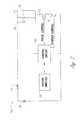
- FIG. 10is a block diagram of the control circuit 130 for one embodiment of illumination system 100 .
- An Oscillator 15(in the embodiment shown, oscillator 15 is part of an image processor as shown which is coupled to an electronic camera 14 , e.g., a charge-coupled device (CCD)), controlled by pulse-frequency circuit (such as circuit 833 of FIG. 8 or frequency generator 433 of FIG. 4 ), sends a trigger signal to power supply 20 .
- the image processor 15generates one pulse or a plurality of pulses for each CCD frame, wherein the number of pulses generated is sufficient to provide a desired accumulation of light received by camera 14 for each frame.
- the trigger signalactivates pulse generator 201 to generate a control pulse of a length determined by pulse-length circuit (such as PWM circuit 834 of FIG. 8 or PWM 434 of FIG. 4 )
- the control pulseis used to turn on transistor Q 1 to generate a flash on LEDs 25 , which is current-limited by resistor R 3 .
- the control pulsealso activates the maximum-rate-limit circuit 202 , which inhibits any further control pulses from pulse generator 201 for a predetermined amount of time.
- the 12 volt signal from power supply 20is filtered by the low-pass filter comprising C 1 , L 1 , D 1 , and R 1 , and charges capacitors C 2 through C N (in one embodiment, N is 12).
- C 1 through C 12are each 2200 ⁇ F
- L 1is 40 ⁇ H iron-core
- D 1as a 1N4001 diode
- R 1is a 0 ohm conductor.
- C 2 through C Nare discharged through fifteen series-wired LEDs 25 , which in this embodiment are wired in a parallel-series manner as shown, and R 3 and Q 1 , as activated by the above-described control pulse.
- R 3is replaced by a zero-ohm conductor, and the voltage drop across the LEDs and Q 1 is used to self-limit the current through the LEDs.
- the control pulseis fed across resistor R 2 , which in one embodiment is 100 K ⁇ , to develop the necessary voltage for driving transistor Q 1 , which in this embodiment is a MTP75NO5HD MOSFET.
- FIG. 11is a more-detailed schematic diagram of power supply 20 .
- the input triggeris fed through resistor R 2 to drive the input of opto-isolator OI 1
- the output of opto-isolator OI 1is coupled through capacitor C 12 (and the associated circuit R 4 , R 6 and D 2 ) to the TRG input of timer circuit 1 C 1 A .
- timers 1 C 1 A and 1 C 1 Bare each 1 ⁇ 2 of a 556-type dual timer.
- the timing constant of timer 1 C 1 Ais set by C 14 and R 1 - x , (where x is selected from 1 through N), and determines the pulse width of the control pulse driving Q 1 , and thus the LEDs.
- five selectable pulse widthsare predetermined and selected by SW 1 , which is a five-way exclusive dual-pole-single-throw switch, wherein one resistor of the set R 1 - 1 through R 1 -N is selected for connection to the DIS input pin of 1 C 1 A , and a corresponding one resistor of the set R 2 - 1 through R 2 -N is selected for connection to the DIS input pin of 1 C 1 B .
- the timing constant of timer 1 C 1 Bis set by C 17 and R 2 - x , (where x is selected from 1 through N), and determines the minimum time between control pulses driving Q 1 , and thus the LEDs.
- the five selectable predetermined pulse widthsare 25 microseconds ( ⁇ s), 50 ⁇ s, 100 ⁇ s, 200 ⁇ s and 500 ⁇ s; the corresponding maximum pulse rates controlled by maximum rate limit circuit 202 are 200 Hz, 120 Hz, 60 Hz, 30 Hz, and 10 Hz, respectively, and are predetermined and selected by SW 1 .
- 100 ⁇ s-long control pulsesare used to activate LEDs 25 .
- a shroudis used to reduce the ambient light, and a red filter (substantially transparent to the peak wavelength of illumination source 18 ) is placed over the lens of imaging device 14 in order to reduce ambient light and pass the light of illumination source 18 .
- the control pulse output signalis driven through resistor R 3 .
- opto-isolator OI 1is a 4N37-type part
- resistor R 2is 100 ⁇
- resistor R 3is 100 ⁇
- resistor R 7is 1 M ⁇
- resistor R 8is 1 K ⁇
- visible-color LED D 3indicates when the circuit is active
- resistor R 4is 4700 ⁇
- resistor R 5is 10 ⁇
- resistor R 6is 10 K ⁇
- diode D 2is a 1N914
- resistor R 1 - 1is 2.26 K ⁇
- resistor R 1 - 2is 4.53 K ⁇
- resistor R 1 - 3is 9.1 K ⁇
- resistor R 1 - 4is 18.2K ⁇
- resistor R 1 - 5is 45.3 K ⁇
- resistor R 2 - 1is 37.4 K ⁇
- resistor R 2 - 2is 75 K ⁇
- resistor R 2 - 3is 150 K ⁇
- resistor R 2 - 4is 301 K ⁇
- resistor R 2 - 5is 909 K ⁇
Landscapes
- Engineering & Computer Science (AREA)
- Multimedia (AREA)
- Signal Processing (AREA)
- General Engineering & Computer Science (AREA)
- Led Devices (AREA)
- Circuit Arrangement For Electric Light Sources In General (AREA)
- Studio Devices (AREA)
Abstract
Description
Claims (20)
Priority Applications (6)
| Application Number | Priority Date | Filing Date | Title |
|---|---|---|---|
| US12/820,139US8159146B1 (en) | 1998-03-19 | 2010-06-22 | Apparatus and method for pulsed L.E.D. illumination |
| US13/244,481US8362712B1 (en) | 1998-03-19 | 2011-09-25 | Apparatus and method for L.E.D. illumination |
| US13/736,865US8643305B2 (en) | 1998-03-19 | 2013-01-08 | Apparatus for L.E.D. illumination |
| US14/049,188US8829808B1 (en) | 1998-03-19 | 2013-10-08 | Apparatus and method for pulsed L.E.D. illumination |
| US14/480,630US9119266B1 (en) | 1998-03-19 | 2014-09-08 | Pulsed L.E.D. illumination apparatus and method |
| US14/835,432US9907137B1 (en) | 1998-03-19 | 2015-08-25 | Pulsed L.E.D. illumination |
Applications Claiming Priority (8)
| Application Number | Priority Date | Filing Date | Title |
|---|---|---|---|
| US09/044,559US6095661A (en) | 1998-03-19 | 1998-03-19 | Method and apparatus for an L.E.D. flashlight |
| US09/627,268US6305818B1 (en) | 1998-03-19 | 2000-07-28 | Method and apparatus for L.E.D. illumination |
| US09/978,760US6488390B1 (en) | 1998-03-19 | 2001-10-16 | Color-adjusted camera light and method |
| US10/299,609US6808287B2 (en) | 1998-03-19 | 2002-11-18 | Method and apparatus for a pulsed L.E.D. illumination source |
| US10/945,801US7186000B2 (en) | 1998-03-19 | 2004-09-20 | Method and apparatus for a variable intensity pulsed L.E.D. light |
| US11/674,143US7393119B2 (en) | 1998-03-19 | 2007-02-12 | Method and apparatus for constant light output pulsed L.E.D. illumination |
| US12/166,315US7740371B1 (en) | 1998-03-19 | 2008-07-01 | Method and apparatus for pulsed L.E.D. illumination for a camera |
| US12/820,139US8159146B1 (en) | 1998-03-19 | 2010-06-22 | Apparatus and method for pulsed L.E.D. illumination |
Related Parent Applications (1)
| Application Number | Title | Priority Date | Filing Date |
|---|---|---|---|
| US12/166,315DivisionUS7740371B1 (en) | 1998-03-19 | 2008-07-01 | Method and apparatus for pulsed L.E.D. illumination for a camera |
Related Child Applications (1)
| Application Number | Title | Priority Date | Filing Date |
|---|---|---|---|
| US13/244,481DivisionUS8362712B1 (en) | 1998-03-19 | 2011-09-25 | Apparatus and method for L.E.D. illumination |
Publications (1)
| Publication Number | Publication Date |
|---|---|
| US8159146B1true US8159146B1 (en) | 2012-04-17 |
Family
ID=38139067
Family Applications (7)
| Application Number | Title | Priority Date | Filing Date |
|---|---|---|---|
| US12/166,315Expired - Fee RelatedUS7740371B1 (en) | 1998-03-19 | 2008-07-01 | Method and apparatus for pulsed L.E.D. illumination for a camera |
| US12/820,139Expired - Fee RelatedUS8159146B1 (en) | 1998-03-19 | 2010-06-22 | Apparatus and method for pulsed L.E.D. illumination |
| US13/244,481Expired - Fee RelatedUS8362712B1 (en) | 1998-03-19 | 2011-09-25 | Apparatus and method for L.E.D. illumination |
| US13/736,865Expired - Fee RelatedUS8643305B2 (en) | 1998-03-19 | 2013-01-08 | Apparatus for L.E.D. illumination |
| US14/049,188Expired - Fee RelatedUS8829808B1 (en) | 1998-03-19 | 2013-10-08 | Apparatus and method for pulsed L.E.D. illumination |
| US14/480,630Expired - Fee RelatedUS9119266B1 (en) | 1998-03-19 | 2014-09-08 | Pulsed L.E.D. illumination apparatus and method |
| US14/835,432Expired - Fee RelatedUS9907137B1 (en) | 1998-03-19 | 2015-08-25 | Pulsed L.E.D. illumination |
Family Applications Before (1)
| Application Number | Title | Priority Date | Filing Date |
|---|---|---|---|
| US12/166,315Expired - Fee RelatedUS7740371B1 (en) | 1998-03-19 | 2008-07-01 | Method and apparatus for pulsed L.E.D. illumination for a camera |
Family Applications After (5)
| Application Number | Title | Priority Date | Filing Date |
|---|---|---|---|
| US13/244,481Expired - Fee RelatedUS8362712B1 (en) | 1998-03-19 | 2011-09-25 | Apparatus and method for L.E.D. illumination |
| US13/736,865Expired - Fee RelatedUS8643305B2 (en) | 1998-03-19 | 2013-01-08 | Apparatus for L.E.D. illumination |
| US14/049,188Expired - Fee RelatedUS8829808B1 (en) | 1998-03-19 | 2013-10-08 | Apparatus and method for pulsed L.E.D. illumination |
| US14/480,630Expired - Fee RelatedUS9119266B1 (en) | 1998-03-19 | 2014-09-08 | Pulsed L.E.D. illumination apparatus and method |
| US14/835,432Expired - Fee RelatedUS9907137B1 (en) | 1998-03-19 | 2015-08-25 | Pulsed L.E.D. illumination |
Country Status (1)
| Country | Link |
|---|---|
| US (7) | US7740371B1 (en) |
Cited By (15)
| Publication number | Priority date | Publication date | Assignee | Title |
|---|---|---|---|---|
| US20080232079A1 (en)* | 2007-03-19 | 2008-09-25 | Fujifilm Corporation | Illumination device and method, and apparatus for image taking |
| US20110025139A1 (en)* | 2009-08-03 | 2011-02-03 | Schulte David J | Power generator |
| US20110127776A1 (en)* | 2009-08-03 | 2011-06-02 | Schulte David J | Power generator |
| US20120133205A1 (en)* | 2010-11-30 | 2012-05-31 | Bayco Products, Ltd. | Programmed Control of a Handheld Battery Operated Device |
| US20130010468A1 (en)* | 2009-05-28 | 2013-01-10 | Zon Led Llc | Led assembly for a signage illumination |
| US8362712B1 (en)* | 1998-03-19 | 2013-01-29 | Led Tech Development, Llc | Apparatus and method for L.E.D. illumination |
| WO2014067830A1 (en)* | 2012-10-31 | 2014-05-08 | Tridonic Jennersdorf Gmbh | Method and arrangement for the temperature-corrected control of leds using look-up tables |
| EP3038433A3 (en)* | 2014-12-23 | 2016-07-27 | PINTSCH BAMAG Antriebs- und Verkehrstechnik GmbH | Led light module, signal light with such a light module and method for operating such a light module |
| CN109358766A (en)* | 2012-09-26 | 2019-02-19 | 谷歌有限责任公司 | The progress of handwriting input is shown |
| USD904657S1 (en) | 2018-04-27 | 2020-12-08 | Milwaukee Electric Tool Corporation | Light |
| US11035556B2 (en) | 2018-04-27 | 2021-06-15 | Milwaukee Electric Tool Corporation | Portable lighting device |
| US11448372B2 (en) | 2019-11-22 | 2022-09-20 | Milwaukee Electric Tool Corporation | Work light |
| US11589434B2 (en) | 2018-11-30 | 2023-02-21 | Milwaukee Electric Tool Corporation | Portable lighting device |
| US11672068B2 (en) | 2020-12-22 | 2023-06-06 | Milwaukee Electric Tool Corporation | Lighting device with state of charge based control |
| USD1032902S1 (en) | 2020-06-22 | 2024-06-25 | Milwaukee Electric Tool Corporation | Work light |
Families Citing this family (53)
| Publication number | Priority date | Publication date | Assignee | Title |
|---|---|---|---|---|
| CN101400201A (en)* | 2007-09-27 | 2009-04-01 | 佛山普立华科技有限公司 | Light source control device and method |
| TWI395511B (en)* | 2008-08-07 | 2013-05-01 | Orise Technology Co Ltd | Display module, LED driver and power control circuit |
| US7965048B2 (en)* | 2008-10-16 | 2011-06-21 | Capella Microsystems, Corp. | Switching converter for lighting with light intensity as feedback and light emitting apparatus using the same |
| JP2012124478A (en) | 2010-11-19 | 2012-06-28 | Semiconductor Energy Lab Co Ltd | Illuminating device |
| US9633584B2 (en)* | 2011-07-05 | 2017-04-25 | Jeffrey L. Underwood | Electrical outlet cover plate with signage feature |
| EP2735211B1 (en)* | 2011-07-20 | 2018-04-18 | Philips Lighting Holding B.V. | Light source comprising a led strip |
| JP5800192B2 (en)* | 2011-10-11 | 2015-10-28 | 富士電機株式会社 | Photocoupler output signal receiving circuit |
| US9553034B1 (en)* | 2012-03-27 | 2017-01-24 | Kla-Tencor Corporation | Combined semiconductor metrology system |
| JP5806972B2 (en)* | 2012-04-27 | 2015-11-10 | セイコーインスツル株式会社 | Output driver circuit |
| CO6820274A1 (en)* | 2012-06-26 | 2013-12-31 | Velez Juan Camilo Diaz | LED light of ultra low consumption multiplexed |
| TWM444531U (en)* | 2012-08-10 | 2013-01-01 | Vivotek Inc | Photographing apparatus |
| CN102917516B (en)* | 2012-11-14 | 2015-04-29 | 深圳市华星光电技术有限公司 | Method for resolving excess temperature of constant current driving chips and light-emitting diode (LED) lamp bar driving circuit |
| US9538593B2 (en)* | 2012-11-14 | 2017-01-03 | Shenzhen China Star Optoelectronics Technology Co., Ltd. | Method for multiplying current of LED light bar and associated driving circuit thereof |
| US9060404B2 (en)* | 2012-11-20 | 2015-06-16 | RedBeard Ventures LLC | Synchronized light source for rolling shutter imagers |
| US9307600B2 (en) | 2012-11-20 | 2016-04-05 | RedBeard Ventures LLC | Synchronized light source for rolling shutter imagers |
| US20140152186A1 (en)* | 2012-11-30 | 2014-06-05 | Shenzhen China Star Optoelectronics Co., Ltd | Led backlight driving circuit, backlight module, and lcd device |
| US20140191667A1 (en)* | 2013-01-08 | 2014-07-10 | Oldenburg Group Incorporated | Light source controller |
| WO2014189247A1 (en)* | 2013-05-20 | 2014-11-27 | Sohn Dae Up | Portable lantern |
| KR101623804B1 (en) | 2013-05-20 | 2016-05-25 | 손대업 | Portable lantern |
| US9335109B2 (en)* | 2013-08-16 | 2016-05-10 | Maiquel Bensayan | Realtime memorialization firearm attachment |
| JP6471883B2 (en)* | 2013-10-02 | 2019-02-20 | パナソニックIpマネジメント株式会社 | Lighting device |
| WO2015061236A1 (en)* | 2013-10-21 | 2015-04-30 | Heinz Grether Pc | A video and lighting control synchronizing system |
| US9474118B2 (en)* | 2013-11-22 | 2016-10-18 | Microchip Technology Inc. | Cascode-type dimming switch using a bipolar junction transistor for driving a string of light emitting diodes |
| DE102013113053B4 (en)* | 2013-11-26 | 2019-03-28 | Schott Ag | Driver circuit with a semiconductor light source and method for operating a driver circuit |
| US20160302271A1 (en)* | 2014-04-10 | 2016-10-13 | Clinton O. Fruitman | Power Conserving Method for Electric Lighting Supply |
| US9474128B2 (en)* | 2014-08-15 | 2016-10-18 | Phase Final, Inc. | Lighting device with ambient light sensor |
| AU2014408234A1 (en)* | 2014-10-28 | 2016-05-12 | Taolight Company Limited | A dimmable LED module and method of using same |
| WO2016118149A1 (en)* | 2015-01-23 | 2016-07-28 | Ramin Soheili | Programming leds in embedded devices |
| ES2868777T3 (en) | 2015-03-06 | 2021-10-21 | The Trustees For The Time Being Of Junior Barnes Family Trust | Image capture system and method for obtaining images of objects in cyclical movement |
| US10078055B2 (en)* | 2015-05-19 | 2018-09-18 | AVID Labs, LLC | LED strobe |
| US9528692B2 (en)* | 2015-05-22 | 2016-12-27 | Gabriel S. Kohn | Personal lighting system |
| US10057964B2 (en) | 2015-07-02 | 2018-08-21 | Hayward Industries, Inc. | Lighting system for an environment and a control module for use therein |
| CN106375705B (en)* | 2015-07-21 | 2019-09-17 | 杭州海康威视数字技术股份有限公司 | Prevent the mthods, systems and devices that thermal camera is restarted |
| US10015412B2 (en) | 2016-09-06 | 2018-07-03 | The Trustees For The Time Being Of Junior Barnes Family Trust | Video capturing system and method for imaging cyclically moving objects |
| JPWO2018101394A1 (en)* | 2016-12-01 | 2019-10-24 | ソニー株式会社 | Information processing apparatus, information processing method, and program |
| US10278254B2 (en) | 2016-12-02 | 2019-04-30 | Sterno Home Inc. | Illumination system with color-changing lights |
| AU2017395528B2 (en) | 2017-01-27 | 2020-05-14 | HotaluX, Ltd. | Chained flashlight system |
| PL3426007T3 (en)* | 2017-07-07 | 2023-05-08 | Burkhard Herbach | Vehicle lighting device with power control |
| US10904449B2 (en)* | 2017-07-31 | 2021-01-26 | Disney Enterprises, Inc. | Intrinsic color camera |
| CN115695769A (en)* | 2018-03-09 | 2023-02-03 | 马克斯-普朗克科学促进学会 | System for displaying information to a user |
| JP6893287B2 (en)* | 2018-09-06 | 2021-06-23 | 株式会社Fuji | Lighting equipment for imaging and component mounting machine |
| US10996543B2 (en) | 2018-09-24 | 2021-05-04 | Light & Motion Industries | Combination high power LED strobe and continuous light |
| UA118644C2 (en)* | 2018-09-25 | 2019-02-11 | Василь Олександрович Руських | PORTABLE PORTABLE LIGHTING DEVICE FOR UNDERWATER PHOTOS AND VIDEOS |
| KR102553487B1 (en)* | 2018-10-26 | 2023-07-07 | 엘지전자 주식회사 | Camera, and terminal including the same |
| JP7204456B2 (en)* | 2018-12-04 | 2023-01-16 | キヤノン株式会社 | Strobe device and its control method and program |
| CN109819553A (en)* | 2019-03-21 | 2019-05-28 | 马艺 | LED light adaptive model regulating system |
| CN113133164B (en)* | 2019-12-30 | 2023-04-25 | 苏州佳世达光电有限公司 | Brightness adjusting circuit |
| DE102020116008A1 (en)* | 2020-06-17 | 2021-12-23 | ABUS August Bremicker Söhne Kommanditgesellschaft | Portable electronic lock |
| US11212892B1 (en)* | 2020-06-18 | 2021-12-28 | Streamlight, Inc. | Variable frequency PWM LED control circuit and method |
| US12022583B2 (en)* | 2020-07-10 | 2024-06-25 | Asiatelco Technologies, Inc. | Portable devices, systems and methods with automated heat control assembly |
| EP4396488B1 (en)* | 2021-08-30 | 2025-06-11 | Signify Holding B.V. | A lighting device |
| US12170841B2 (en)* | 2022-08-29 | 2024-12-17 | Cisco Technology, Inc. | Power reduction for LEDs based on infrared pulsing |
| CN116204868A (en)* | 2022-12-30 | 2023-06-02 | 支付宝(杭州)信息技术有限公司 | A security verification device, a security verification method, device and medium |
Citations (55)
| Publication number | Priority date | Publication date | Assignee | Title |
|---|---|---|---|---|
| US1445245A (en) | 1921-12-19 | 1923-02-13 | Winchester Repeating Arms Co | Spotlight |
| US3001185A (en) | 1959-09-14 | 1961-09-19 | Charles L Cleek | Morse code hand signaling devices |
| US3693060A (en) | 1971-04-13 | 1972-09-19 | Philips Corp | Solid-state relay using light-emitting diodes |
| US3902806A (en) | 1974-04-22 | 1975-09-02 | American Optical Corp | Constant current-pulse led drive circuit |
| US4068148A (en) | 1975-10-14 | 1978-01-10 | Hitachi, Ltd. | Constant current driving circuit |
| US4139348A (en) | 1975-11-28 | 1979-02-13 | Massachusetts Institute Of Technology | Electrochemical process and apparatus to control the chemical state of a material |
| US4208579A (en) | 1978-02-02 | 1980-06-17 | Vicon Products Corp. | Electrically isolated control means for the illuminating source of a dental drill |
| US4212073A (en) | 1978-12-13 | 1980-07-08 | Balasubramanian N | Method and system for surface contouring |
| US4290095A (en) | 1979-08-27 | 1981-09-15 | Schmidt Robert C H | Aiming post light |
| US4346329A (en) | 1979-08-27 | 1982-08-24 | Schmidt Robert C H | Aiming post light |
| US4347499A (en) | 1981-01-02 | 1982-08-31 | Thomas F. Burkman, Sr. | Emergency guidance system |
| US4403157A (en) | 1982-02-08 | 1983-09-06 | Teledyne Industries, Inc. | Control circuit for light emitting diode |
| US4447150A (en) | 1981-02-27 | 1984-05-08 | Bentley Laboratories | Apparatus and method for measuring blood oxygen saturation |
| US4509266A (en) | 1982-06-14 | 1985-04-09 | Gte Valeron Corporation | Touch probe |
| US4592147A (en) | 1983-05-31 | 1986-06-03 | Herman Robert D | Electrically actuated angular orientation indicating device |
| US4626765A (en)* | 1983-05-25 | 1986-12-02 | Japan Storage Battery Company Limited | Apparatus for indicating remaining battery capacity |
| US4641972A (en) | 1984-09-14 | 1987-02-10 | New York Institute Of Technology | Method and apparatus for surface profilometry |
| US4644342A (en) | 1984-03-29 | 1987-02-17 | Eastman Kodak Company | Array of light emitting diodes for producing gray scale light images |
| US4748350A (en) | 1980-12-20 | 1988-05-31 | Fujitsu Limited | Emitter-coupled logic circuit |
| US4820229A (en) | 1987-02-17 | 1989-04-11 | Spraggins Gary L | Amusement device |
| US4831504A (en) | 1985-11-13 | 1989-05-16 | Junichi Nishizawa | Holder with semiconductor lighting device |
| US4845481A (en) | 1986-01-08 | 1989-07-04 | Karel Havel | Continuously variable color display device |
| US4882498A (en) | 1987-10-09 | 1989-11-21 | Pressco, Inc. | Pulsed-array video inspection lighting system |
| US4893815A (en) | 1987-08-27 | 1990-01-16 | Larry Rowan | Interactive transector device commercial and military grade |
| US4914289A (en) | 1988-10-26 | 1990-04-03 | Inex-Vistech Technologies Incorporated | Article inspection system for analyzing end and adjacent sides |
| US4962347A (en) | 1988-02-25 | 1990-10-09 | Strategic Energy, Ltd. | Flashlight with battery tester |
| US4965665A (en) | 1989-10-25 | 1990-10-23 | At&T Bell Laboratories | 3D imaging of a substrate using perpendicular scanning directions |
| US4972093A (en) | 1987-10-09 | 1990-11-20 | Pressco Inc. | Inspection lighting system |
| US4978857A (en) | 1981-04-30 | 1990-12-18 | Gte Valenite Corporation | Optical data system having flash/receiver head for energizing/receiving information from a battery operated transmitter |
| US5008788A (en) | 1990-04-02 | 1991-04-16 | Electronic Research Associates, Inc. | Multi-color illumination apparatus |
| US5010412A (en) | 1988-12-27 | 1991-04-23 | The Boeing Company | High frequency, low power light source for video camera |
| US5015918A (en) | 1988-07-22 | 1991-05-14 | John Copeland | Bicycle single-wire lighting system with steady-flashing-reflector rear warning device |
| US5051825A (en) | 1989-04-07 | 1991-09-24 | Pressco, Inc. | Dual image video inspection apparatus |
| US5065035A (en) | 1981-04-30 | 1991-11-12 | Gte Valenite Corporation | Optical data system having flash/receiver head for energizing/receiving information from a battery operated transmitter |
| US5072127A (en) | 1987-10-09 | 1991-12-10 | Pressco, Inc. | Engineered video inspecting lighting array |
| US5099139A (en) | 1989-05-24 | 1992-03-24 | Nec Corporation | Voltage-current converting circuit having an output switching function |
| US5172005A (en) | 1991-02-20 | 1992-12-15 | Pressco Technology, Inc. | Engineered lighting system for tdi inspection comprising means for controlling lighting elements in accordance with specimen displacement |
| US5179335A (en) | 1987-10-09 | 1993-01-12 | Norvik Inc. | Battery charger |
| US5279513A (en) | 1991-11-27 | 1994-01-18 | I & K Trading Corporation | Illuminating toy |
| US5299227A (en) | 1993-04-13 | 1994-03-29 | American Electronics, Inc. | Individual beacon identification system |
| US5355221A (en) | 1991-06-12 | 1994-10-11 | Wyko Corporation | Rough surface profiler and method |
| US5398113A (en) | 1993-02-08 | 1995-03-14 | Zygo Corporation | Method and apparatus for surface topography measurement by spatial-frequency analysis of interferograms |
| US5424927A (en) | 1991-06-27 | 1995-06-13 | Rayovac Corporation | Electro-optic flashlight electro-optically controlling the emitted light |
| US5563703A (en) | 1994-06-20 | 1996-10-08 | Motorola, Inc. | Lead coplanarity inspection apparatus and method thereof |
| US5646733A (en) | 1996-01-29 | 1997-07-08 | Medar, Inc. | Scanning phase measuring method and system for an object at a vision station |
| US5745176A (en) | 1995-10-12 | 1998-04-28 | Ppt Vision, Inc. | Machine-vision illumination system and method for delineating a lighted volume from an unlighted volume |
| US5783909A (en)* | 1997-01-10 | 1998-07-21 | Relume Corporation | Maintaining LED luminous intensity |
| US5815018A (en) | 1996-07-16 | 1998-09-29 | Systech Solutions, Inc. | Pulse modulator circuit for an illuminator system |
| US5838247A (en) | 1997-04-01 | 1998-11-17 | Bladowski; Witold S. | Solid state light system |
| US5890794A (en) | 1996-04-03 | 1999-04-06 | Abtahi; Homayoon | Lighting units |
| US6016038A (en) | 1997-08-26 | 2000-01-18 | Color Kinetics, Inc. | Multicolored LED lighting method and apparatus |
| US6095661A (en) | 1998-03-19 | 2000-08-01 | Ppt Vision, Inc. | Method and apparatus for an L.E.D. flashlight |
| US6263099B1 (en) | 1994-10-07 | 2001-07-17 | Hitachi, Ltd. | Manufacturing method of semiconductor substrate and method and apparatus for inspecting defects of patterns of an object to be inspected |
| US6357893B1 (en) | 2000-03-15 | 2002-03-19 | Richard S. Belliveau | Lighting devices using a plurality of light sources |
| US8044815B2 (en)* | 2006-03-03 | 2011-10-25 | O2Micro Inc | Systems and methods for battery status indication |
Family Cites Families (78)
| Publication number | Priority date | Publication date | Assignee | Title |
|---|---|---|---|---|
| DE1804756A1 (en) | 1968-10-23 | 1970-08-06 | Dr Ernst Froeschle | Optical mass storage for digital computers |
| US3617859A (en) | 1970-03-23 | 1971-11-02 | Nat Semiconductor Corp | Electrical regulator apparatus including a zero temperature coefficient voltage reference circuit |
| GB1383548A (en) | 1972-06-29 | 1974-02-12 | Plessey Co Ltd | Light emitting diode assembly |
| US3764862A (en) | 1972-10-19 | 1973-10-09 | Fairchild Camera Instr Co | Lead frame for light-emitting diodes |
| US3914786A (en) | 1974-04-19 | 1975-10-21 | Hewlett Packard Co | In-line reflective lead-pair for light-emitting diodes |
| US4237405A (en) | 1978-03-10 | 1980-12-02 | Lear Siegler, Inc. | Method and apparatus for conserving energy |
| US4326161A (en) | 1979-10-17 | 1982-04-20 | Protection Services, Inc. | Battery regulation circuit |
| US4368406A (en) | 1980-12-29 | 1983-01-11 | Ford Motor Company | Lamp dimmer control with integral ambient sensor |
| US4409645A (en) | 1981-10-09 | 1983-10-11 | Sloan Francis J | Combination flashlight and auxiliary power pack |
| US4499525A (en) | 1981-12-16 | 1985-02-12 | Duracell Inc. | Constant illumination flashlight |
| JPS58149033A (en) | 1982-03-02 | 1983-09-05 | Minolta Camera Co Ltd | Flash emitting device |
| US4409643A (en) | 1982-03-23 | 1983-10-11 | Frank Alan M | Long lifetime, low intensity light source for use in nighttime viewing of equipment maps and other writings |
| US4514727A (en) | 1982-06-28 | 1985-04-30 | Trw Inc. | Automatic brightness control apparatus |
| US5184114A (en) | 1982-11-04 | 1993-02-02 | Integrated Systems Engineering, Inc. | Solid state color display system and light emitting diode pixels therefor |
| JPH0670682B2 (en) | 1983-08-19 | 1994-09-07 | 日照技研株式会社 | Lighting equipment |
| US4743773A (en) | 1984-08-23 | 1988-05-10 | Nippon Electric Industry Co., Ltd. | Bar code scanner with diffusion filter and plural linear light source arrays |
| FR2587614B1 (en) | 1985-09-23 | 1988-01-15 | Biomasys Sa | PROSTHETIC HEART VALVE |
| US4639139A (en) | 1985-09-27 | 1987-01-27 | Wyko Corporation | Optical profiler using improved phase shifting interferometry |
| JPS62104363A (en) | 1985-10-31 | 1987-05-14 | Yokogawa Medical Syst Ltd | Multi-frame photographing device |
| US4673865A (en) | 1986-04-04 | 1987-06-16 | Motorola, Inc. | Charge coupled LED driver circuit |
| US4698730A (en) | 1986-08-01 | 1987-10-06 | Stanley Electric Co., Ltd. | Light-emitting diode |
| US4847680A (en) | 1986-09-24 | 1989-07-11 | Canon Kabushiki Kaisha | Image pickup apparatus with white balance control |
| US6323832B1 (en) | 1986-09-27 | 2001-11-27 | Junichi Nishizawa | Color display device |
| US5085502A (en) | 1987-04-30 | 1992-02-04 | Eastman Kodak Company | Method and apparatus for digital morie profilometry calibrated for accurate conversion of phase information into distance measurements in a plurality of directions |
| US4967284A (en) | 1987-10-19 | 1990-10-30 | Ricoh Company, Ltd. | Image forming apparatus and method of controlling output of semiconductor laser |
| US4841198A (en) | 1987-10-19 | 1989-06-20 | Nartron Corporation | Head lamp control method and apparatus, with PWM output regulation |
| US4877326A (en) | 1988-02-19 | 1989-10-31 | Kla Instruments Corporation | Method and apparatus for optical inspection of substrates |
| US5059013A (en) | 1988-08-29 | 1991-10-22 | Kantilal Jain | Illumination system to produce self-luminous light beam of selected cross-section, uniform intensity and selected numerical aperture |
| US4959755A (en) | 1989-02-13 | 1990-09-25 | Hochstein Peter A | Automatic battery powered video light |
| US5012392A (en) | 1989-02-13 | 1991-04-30 | Hochstein Peter A | Automatic battery powered video light |
| US4992704A (en)* | 1989-04-17 | 1991-02-12 | Basic Electronics, Inc. | Variable color light emitting diode |
| US5058982A (en) | 1989-06-21 | 1991-10-22 | Orbot Systems Ltd. | Illumination system and inspection apparatus including same |
| US5175528A (en) | 1989-10-11 | 1992-12-29 | Grace Technology, Inc. | Double oscillator battery powered flashing superluminescent light emitting diode safety warning light |
| US5134387A (en) | 1989-11-06 | 1992-07-28 | Texas Digital Systems, Inc. | Multicolor display system |
| US5060065A (en) | 1990-02-23 | 1991-10-22 | Cimflex Teknowledge Corporation | Apparatus and method for illuminating a printed circuit board for inspection |
| KR940001691B1 (en) | 1990-06-25 | 1994-03-05 | 가부시기가이샤 도시바 | Battery-operated personal computer |
| JP3263924B2 (en)* | 1990-09-14 | 2002-03-11 | ソニー株式会社 | Color imaging device |
| US5488623A (en) | 1990-11-07 | 1996-01-30 | Fuji Electric Co., Ltd. | Mold-type semiconductor laser device with reduced light-emitting point displacement during operation |
| US5179474A (en) | 1991-03-21 | 1993-01-12 | Delta Technology Corporation | Viewer for a sorting machine |
| EP0539640A1 (en)* | 1991-10-30 | 1993-05-05 | Texas Instruments Limited | Improvements in or relating to batteries |
| US5354977A (en)* | 1992-02-27 | 1994-10-11 | Alex Roustaei | Optical scanning head |
| US5636025A (en) | 1992-04-23 | 1997-06-03 | Medar, Inc. | System for optically measuring the surface contour of a part using more fringe techniques |
| US5359185A (en) | 1992-05-11 | 1994-10-25 | Norand Corporation | Chromatic ranging method and apparatus for reading optically readable information over a substantial range of distances |
| US5272327A (en) | 1992-05-26 | 1993-12-21 | Compaq Computer Corporation | Constant brightness liquid crystal display backlight control system |
| US5485201A (en) | 1992-08-28 | 1996-01-16 | Asahi Kogaku Kogyo Kabushiki Kaisha | Fill-in light emitting apparatus and still video camera |
| JP2858430B2 (en) | 1993-04-22 | 1999-02-17 | キヤノン株式会社 | Camera with automatic flash function |
| JP3384035B2 (en) | 1993-06-21 | 2003-03-10 | ソニー株式会社 | Lamp drive |
| JP3517903B2 (en) | 1993-06-21 | 2004-04-12 | 株式会社ニコン | Interferometer |
| KR100269731B1 (en) | 1993-07-15 | 2000-10-16 | 하루타 히로시 | Light source device for image processor |
| JPH0750775A (en) | 1993-08-09 | 1995-02-21 | Hitachi Ltd | VTR integrated video camera |
| EP0638801B1 (en) | 1993-08-12 | 1998-12-23 | International Business Machines Corporation | Method of inspecting the array of balls of an integrated circuit module |
| US5815204A (en) | 1993-10-04 | 1998-09-29 | Asahi Kogaku Kogyo Kabushiki Kaisha | Strobe apparatus of a still video camera with adjustable color temperature |
| US5373387A (en) | 1993-10-14 | 1994-12-13 | At&T Corp. | Method for controlling the amplitude of an optical signal |
| US5489771A (en) | 1993-10-15 | 1996-02-06 | University Of Virginia Patent Foundation | LED light standard for photo- and videomicroscopy |
| US5471052A (en)* | 1993-10-25 | 1995-11-28 | Eaton Corporation | Color sensor system using a secondary light receiver |
| US5451979A (en) | 1993-11-04 | 1995-09-19 | Adaptive Micro Systems, Inc. | Display driver with duty cycle control |
| US5546189A (en) | 1994-05-19 | 1996-08-13 | View Engineering, Inc. | Triangulation-based 3D imaging and processing method and system |
| US5465152A (en) | 1994-06-03 | 1995-11-07 | Robotic Vision Systems, Inc. | Method for coplanarity inspection of package or substrate warpage for ball grid arrays, column arrays, and similar structures |
| US5604550A (en) | 1994-10-31 | 1997-02-18 | Northeast Robotics, Inc. | Illumination device for indirectly illuminating an object with continuous diffuse light |
| US5825495A (en) | 1995-02-27 | 1998-10-20 | Lockheed Martin Corporation | Bright field illumination system |
| US5680215A (en) | 1995-02-27 | 1997-10-21 | Lockheed Missiles & Space Company, Inc. | Vision inspection system and method |
| JPH0974224A (en) | 1995-09-05 | 1997-03-18 | Canon Inc | Lighting circuit |
| US5921568A (en) | 1995-10-27 | 1999-07-13 | Chrysler Corporation | Front suspension system with substantially horizontal shock absorber |
| US5765940A (en) | 1995-10-31 | 1998-06-16 | Dialight Corporation | LED-illuminated stop/tail lamp assembly |
| US5758942A (en) | 1995-12-18 | 1998-06-02 | Micron Technology, Inc. | Mechanical vision system using selective wavelength and brightness illumination |
| JPH09322191A (en) | 1996-03-29 | 1997-12-12 | Ricoh Co Ltd | Image input device |
| US5803579A (en) | 1996-06-13 | 1998-09-08 | Gentex Corporation | Illuminator assembly incorporating light emitting diodes |
| US5859924A (en) | 1996-07-12 | 1999-01-12 | Robotic Vision Systems, Inc. | Method and system for measuring object features |
| JPH1093856A (en) | 1996-08-07 | 1998-04-10 | Hewlett Packard Co <Hp> | Solid-state image pickup device |
| US6677936B2 (en) | 1996-10-31 | 2004-01-13 | Kopin Corporation | Color display system for a camera |
| JPH10206942A (en) | 1997-01-21 | 1998-08-07 | Minolta Co Ltd | Flash light emitting device and camera provided with the same |
| US5828449A (en) | 1997-02-26 | 1998-10-27 | Acuity Imaging, Llc | Ring illumination reflective elements on a generally planar surface |
| US5912568A (en) | 1997-03-21 | 1999-06-15 | Lucent Technologies Inc. | Led drive circuit |
| US7038398B1 (en) | 1997-08-26 | 2006-05-02 | Color Kinetics, Incorporated | Kinetic illumination system and methods |
| US5994844A (en) | 1997-12-12 | 1999-11-30 | Frezzolini Electronics, Inc. | Video lighthead with dimmer control and stabilized intensity |
| US6222172B1 (en) | 1998-02-04 | 2001-04-24 | Photobit Corporation | Pulse-controlled light emitting diode source |
| US6236331B1 (en) | 1998-02-20 | 2001-05-22 | Newled Technologies Inc. | LED traffic light intensity controller |
| US7740371B1 (en)* | 1998-03-19 | 2010-06-22 | Charles A. Lemaire | Method and apparatus for pulsed L.E.D. illumination for a camera |
- 2008
- 2008-07-01USUS12/166,315patent/US7740371B1/ennot_activeExpired - Fee Related
- 2010
- 2010-06-22USUS12/820,139patent/US8159146B1/ennot_activeExpired - Fee Related
- 2011
- 2011-09-25USUS13/244,481patent/US8362712B1/ennot_activeExpired - Fee Related
- 2013
- 2013-01-08USUS13/736,865patent/US8643305B2/ennot_activeExpired - Fee Related
- 2013-10-08USUS14/049,188patent/US8829808B1/ennot_activeExpired - Fee Related
- 2014
- 2014-09-08USUS14/480,630patent/US9119266B1/ennot_activeExpired - Fee Related
- 2015
- 2015-08-25USUS14/835,432patent/US9907137B1/ennot_activeExpired - Fee Related
Patent Citations (57)
| Publication number | Priority date | Publication date | Assignee | Title |
|---|---|---|---|---|
| US1445245A (en) | 1921-12-19 | 1923-02-13 | Winchester Repeating Arms Co | Spotlight |
| US3001185A (en) | 1959-09-14 | 1961-09-19 | Charles L Cleek | Morse code hand signaling devices |
| US3693060A (en) | 1971-04-13 | 1972-09-19 | Philips Corp | Solid-state relay using light-emitting diodes |
| US3902806A (en) | 1974-04-22 | 1975-09-02 | American Optical Corp | Constant current-pulse led drive circuit |
| US4068148A (en) | 1975-10-14 | 1978-01-10 | Hitachi, Ltd. | Constant current driving circuit |
| US4139348A (en) | 1975-11-28 | 1979-02-13 | Massachusetts Institute Of Technology | Electrochemical process and apparatus to control the chemical state of a material |
| US4208579A (en) | 1978-02-02 | 1980-06-17 | Vicon Products Corp. | Electrically isolated control means for the illuminating source of a dental drill |
| US4212073A (en) | 1978-12-13 | 1980-07-08 | Balasubramanian N | Method and system for surface contouring |
| US4290095A (en) | 1979-08-27 | 1981-09-15 | Schmidt Robert C H | Aiming post light |
| US4346329A (en) | 1979-08-27 | 1982-08-24 | Schmidt Robert C H | Aiming post light |
| US4748350A (en) | 1980-12-20 | 1988-05-31 | Fujitsu Limited | Emitter-coupled logic circuit |
| US4347499A (en) | 1981-01-02 | 1982-08-31 | Thomas F. Burkman, Sr. | Emergency guidance system |
| US4447150A (en) | 1981-02-27 | 1984-05-08 | Bentley Laboratories | Apparatus and method for measuring blood oxygen saturation |
| US5065035A (en) | 1981-04-30 | 1991-11-12 | Gte Valenite Corporation | Optical data system having flash/receiver head for energizing/receiving information from a battery operated transmitter |
| US4978857A (en) | 1981-04-30 | 1990-12-18 | Gte Valenite Corporation | Optical data system having flash/receiver head for energizing/receiving information from a battery operated transmitter |
| US4403157A (en) | 1982-02-08 | 1983-09-06 | Teledyne Industries, Inc. | Control circuit for light emitting diode |
| US4509266A (en) | 1982-06-14 | 1985-04-09 | Gte Valeron Corporation | Touch probe |
| US4626765A (en)* | 1983-05-25 | 1986-12-02 | Japan Storage Battery Company Limited | Apparatus for indicating remaining battery capacity |
| US4592147A (en) | 1983-05-31 | 1986-06-03 | Herman Robert D | Electrically actuated angular orientation indicating device |
| US4644342A (en) | 1984-03-29 | 1987-02-17 | Eastman Kodak Company | Array of light emitting diodes for producing gray scale light images |
| US4641972A (en) | 1984-09-14 | 1987-02-10 | New York Institute Of Technology | Method and apparatus for surface profilometry |
| US4831504A (en) | 1985-11-13 | 1989-05-16 | Junichi Nishizawa | Holder with semiconductor lighting device |
| US4964023A (en) | 1985-11-13 | 1990-10-16 | Junichi Nishizawa | Holder with semiconductor lighting device |
| US4845481A (en) | 1986-01-08 | 1989-07-04 | Karel Havel | Continuously variable color display device |
| US4820229A (en) | 1987-02-17 | 1989-04-11 | Spraggins Gary L | Amusement device |
| US4893815A (en) | 1987-08-27 | 1990-01-16 | Larry Rowan | Interactive transector device commercial and military grade |
| US4972093A (en) | 1987-10-09 | 1990-11-20 | Pressco Inc. | Inspection lighting system |
| US4882498A (en) | 1987-10-09 | 1989-11-21 | Pressco, Inc. | Pulsed-array video inspection lighting system |
| US5072127A (en) | 1987-10-09 | 1991-12-10 | Pressco, Inc. | Engineered video inspecting lighting array |
| US5179335A (en) | 1987-10-09 | 1993-01-12 | Norvik Inc. | Battery charger |
| US4962347A (en) | 1988-02-25 | 1990-10-09 | Strategic Energy, Ltd. | Flashlight with battery tester |
| US5015918A (en) | 1988-07-22 | 1991-05-14 | John Copeland | Bicycle single-wire lighting system with steady-flashing-reflector rear warning device |
| US4914289A (en) | 1988-10-26 | 1990-04-03 | Inex-Vistech Technologies Incorporated | Article inspection system for analyzing end and adjacent sides |
| US5010412A (en) | 1988-12-27 | 1991-04-23 | The Boeing Company | High frequency, low power light source for video camera |
| US5051825A (en) | 1989-04-07 | 1991-09-24 | Pressco, Inc. | Dual image video inspection apparatus |
| US5099139A (en) | 1989-05-24 | 1992-03-24 | Nec Corporation | Voltage-current converting circuit having an output switching function |
| US4965665A (en) | 1989-10-25 | 1990-10-23 | At&T Bell Laboratories | 3D imaging of a substrate using perpendicular scanning directions |
| US5008788A (en) | 1990-04-02 | 1991-04-16 | Electronic Research Associates, Inc. | Multi-color illumination apparatus |
| US5172005A (en) | 1991-02-20 | 1992-12-15 | Pressco Technology, Inc. | Engineered lighting system for tdi inspection comprising means for controlling lighting elements in accordance with specimen displacement |
| US5355221A (en) | 1991-06-12 | 1994-10-11 | Wyko Corporation | Rough surface profiler and method |
| US5424927A (en) | 1991-06-27 | 1995-06-13 | Rayovac Corporation | Electro-optic flashlight electro-optically controlling the emitted light |
| US5279513A (en) | 1991-11-27 | 1994-01-18 | I & K Trading Corporation | Illuminating toy |
| US5398113A (en) | 1993-02-08 | 1995-03-14 | Zygo Corporation | Method and apparatus for surface topography measurement by spatial-frequency analysis of interferograms |
| US5299227A (en) | 1993-04-13 | 1994-03-29 | American Electronics, Inc. | Individual beacon identification system |
| US5563703A (en) | 1994-06-20 | 1996-10-08 | Motorola, Inc. | Lead coplanarity inspection apparatus and method thereof |
| US6263099B1 (en) | 1994-10-07 | 2001-07-17 | Hitachi, Ltd. | Manufacturing method of semiconductor substrate and method and apparatus for inspecting defects of patterns of an object to be inspected |
| US5745176A (en) | 1995-10-12 | 1998-04-28 | Ppt Vision, Inc. | Machine-vision illumination system and method for delineating a lighted volume from an unlighted volume |
| US5646733A (en) | 1996-01-29 | 1997-07-08 | Medar, Inc. | Scanning phase measuring method and system for an object at a vision station |
| US5890794A (en) | 1996-04-03 | 1999-04-06 | Abtahi; Homayoon | Lighting units |
| US5815018A (en) | 1996-07-16 | 1998-09-29 | Systech Solutions, Inc. | Pulse modulator circuit for an illuminator system |
| US5783909A (en)* | 1997-01-10 | 1998-07-21 | Relume Corporation | Maintaining LED luminous intensity |
| US5838247A (en) | 1997-04-01 | 1998-11-17 | Bladowski; Witold S. | Solid state light system |
| US6016038A (en) | 1997-08-26 | 2000-01-18 | Color Kinetics, Inc. | Multicolored LED lighting method and apparatus |
| US6095661A (en) | 1998-03-19 | 2000-08-01 | Ppt Vision, Inc. | Method and apparatus for an L.E.D. flashlight |
| US6305818B1 (en) | 1998-03-19 | 2001-10-23 | Ppt Vision, Inc. | Method and apparatus for L.E.D. illumination |
| US6357893B1 (en) | 2000-03-15 | 2002-03-19 | Richard S. Belliveau | Lighting devices using a plurality of light sources |
| US8044815B2 (en)* | 2006-03-03 | 2011-10-25 | O2Micro Inc | Systems and methods for battery status indication |
Non-Patent Citations (13)
Cited By (23)
| Publication number | Priority date | Publication date | Assignee | Title |
|---|---|---|---|---|
| US8362712B1 (en)* | 1998-03-19 | 2013-01-29 | Led Tech Development, Llc | Apparatus and method for L.E.D. illumination |
| US20080232079A1 (en)* | 2007-03-19 | 2008-09-25 | Fujifilm Corporation | Illumination device and method, and apparatus for image taking |
| US8385735B2 (en)* | 2007-03-19 | 2013-02-26 | Fujifilm Corporation | Illumination device and method, and apparatus for image taking |
| US20130010468A1 (en)* | 2009-05-28 | 2013-01-10 | Zon Led Llc | Led assembly for a signage illumination |
| US8610357B2 (en)* | 2009-05-28 | 2013-12-17 | Zon Led, Llc | LED assembly for a signage illumination |
| US20110025139A1 (en)* | 2009-08-03 | 2011-02-03 | Schulte David J | Power generator |
| US20110127776A1 (en)* | 2009-08-03 | 2011-06-02 | Schulte David J | Power generator |
| US8203224B2 (en)* | 2009-08-03 | 2012-06-19 | Schulte David J | Power generator |
| US8508057B2 (en)* | 2009-08-03 | 2013-08-13 | David J. Schulte | Power generator |
| US20120133205A1 (en)* | 2010-11-30 | 2012-05-31 | Bayco Products, Ltd. | Programmed Control of a Handheld Battery Operated Device |
| CN109358766B (en)* | 2012-09-26 | 2021-12-21 | 谷歌有限责任公司 | Progress display of handwriting input |
| CN109358766A (en)* | 2012-09-26 | 2019-02-19 | 谷歌有限责任公司 | The progress of handwriting input is shown |
| WO2014067830A1 (en)* | 2012-10-31 | 2014-05-08 | Tridonic Jennersdorf Gmbh | Method and arrangement for the temperature-corrected control of leds using look-up tables |
| EP3038433A3 (en)* | 2014-12-23 | 2016-07-27 | PINTSCH BAMAG Antriebs- und Verkehrstechnik GmbH | Led light module, signal light with such a light module and method for operating such a light module |
| USD904657S1 (en) | 2018-04-27 | 2020-12-08 | Milwaukee Electric Tool Corporation | Light |
| US11035556B2 (en) | 2018-04-27 | 2021-06-15 | Milwaukee Electric Tool Corporation | Portable lighting device |
| US11589434B2 (en) | 2018-11-30 | 2023-02-21 | Milwaukee Electric Tool Corporation | Portable lighting device |
| US11871487B2 (en) | 2018-11-30 | 2024-01-09 | Milwaukee Electric Tool Corporation | Portable lighting device |
| US11448372B2 (en) | 2019-11-22 | 2022-09-20 | Milwaukee Electric Tool Corporation | Work light |
| US11879603B2 (en) | 2019-11-22 | 2024-01-23 | Milwaukee Electric Tool Corporation | Work light |
| US12281762B2 (en) | 2019-11-22 | 2025-04-22 | Milwaukee Electric Tool Corporation | Work light |
| USD1032902S1 (en) | 2020-06-22 | 2024-06-25 | Milwaukee Electric Tool Corporation | Work light |
| US11672068B2 (en) | 2020-12-22 | 2023-06-06 | Milwaukee Electric Tool Corporation | Lighting device with state of charge based control |
Also Published As
| Publication number | Publication date |
|---|---|
| US20130141635A1 (en) | 2013-06-06 |
| US7740371B1 (en) | 2010-06-22 |
| US8643305B2 (en) | 2014-02-04 |
| US9119266B1 (en) | 2015-08-25 |
| US8829808B1 (en) | 2014-09-09 |
| US9907137B1 (en) | 2018-02-27 |
| US8362712B1 (en) | 2013-01-29 |
Similar Documents
| Publication | Publication Date | Title |
|---|---|---|
| US9907137B1 (en) | Pulsed L.E.D. illumination | |
| US6488390B1 (en) | Color-adjusted camera light and method | |
| KR100743254B1 (en) | Infrared dimmer | |
| US5313187A (en) | Battery-powered flashing superluminescent light emitting diode safety warning light | |
| US7923935B2 (en) | Illumination control system for light emitters | |
| US7639219B2 (en) | Burst pulse circuit for signal lights and method | |
| US7938556B2 (en) | Torch | |
| CN111917990B (en) | Video camera | |
| US20080290250A1 (en) | Color Lighting Device | |
| TW200829082A (en) | LED driving circuit | |
| JP3063067U (en) | Portable electric light | |
| CN107219707A (en) | Small-power focusing under water and the LED lamplight control device and method of high-power flash of light switching control | |
| KR0163640B1 (en) | Strobe dimmer with adjustable light intensity and color temperature | |
| US7372441B2 (en) | Burst pulse circuit for signal lights and method | |
| JP5937329B2 (en) | Toning type LED lighting fixture | |
| JP2005340832A (en) | Apparatus and method for controlling spectral content of laser diode light source | |
| CN113853833B (en) | DC-DC converter circuit, LED lighting system and method of operating an LED driver | |
| JP2006010745A (en) | Illuminator | |
| KR970006543B1 (en) | Strobo light -illuminating apparatus capable of controlling light intensity and color temperature | |
| AU2008100631A4 (en) | Improved High Intensity LED Flashlight | |
| JP2005017389A (en) | Lighting system for camera | |
| JP2003084345A (en) | Flash device, camera device including the same, and method for driving light emitting element of flash device |
Legal Events
| Date | Code | Title | Description |
|---|---|---|---|
| AS | Assignment | Owner name:LEMAIRE ILLUMINATION TECHNOLOGIES, LLC, TEXAS Free format text:ASSIGNMENT OF ASSIGNORS INTEREST;ASSIGNOR:LEMAIRE, CHARLES A.;REEL/FRAME:027257/0056 Effective date:20110908 | |
| STCF | Information on status: patent grant | Free format text:PATENTED CASE | |
| AS | Assignment | Owner name:LED TECH DEVELOPMENT, LLC, TEXAS Free format text:ASSIGNMENT OF ASSIGNORS INTEREST;ASSIGNOR:LEMAIRE ILLUMINATION TECHNOLOGIES, LLC;REEL/FRAME:027989/0001 Effective date:20120330 | |
| AS | Assignment | Owner name:LED TECH DEVELOPMENT, LLC, TEXAS Free format text:MERGER;ASSIGNOR:LED TECH DEVELOPMENT, LLC;REEL/FRAME:028268/0337 Effective date:20120516 | |
| FEPP | Fee payment procedure | Free format text:PAT HOLDER NO LONGER CLAIMS SMALL ENTITY STATUS, ENTITY STATUS SET TO UNDISCOUNTED (ORIGINAL EVENT CODE: STOL); ENTITY STATUS OF PATENT OWNER: LARGE ENTITY | |
| FPAY | Fee payment | Year of fee payment:4 | |
| AS | Assignment | Owner name:LEMAIRE ILLUMINATION TECHNOLOGIES, LLC, TEXAS Free format text:ASSIGNMENT OF ASSIGNORS INTEREST;ASSIGNOR:LED TECH DEVELOPMENT, LLC;REEL/FRAME:038505/0128 Effective date:20160506 | |
| FEPP | Fee payment procedure | Free format text:MAINTENANCE FEE REMINDER MAILED (ORIGINAL EVENT CODE: REM.); ENTITY STATUS OF PATENT OWNER: LARGE ENTITY | |
| LAPS | Lapse for failure to pay maintenance fees | Free format text:PATENT EXPIRED FOR FAILURE TO PAY MAINTENANCE FEES (ORIGINAL EVENT CODE: EXP.); ENTITY STATUS OF PATENT OWNER: LARGE ENTITY | |
| STCH | Information on status: patent discontinuation | Free format text:PATENT EXPIRED DUE TO NONPAYMENT OF MAINTENANCE FEES UNDER 37 CFR 1.362 | |
| FP | Lapsed due to failure to pay maintenance fee | Effective date:20200417 |