US8157851B2 - Apparatus and methods for deployment of multiple custom-length prostheses - Google Patents
Apparatus and methods for deployment of multiple custom-length prosthesesDownload PDFInfo
- Publication number
- US8157851B2 US8157851B2US11/148,545US14854505AUS8157851B2US 8157851 B2US8157851 B2US 8157851B2US 14854505 AUS14854505 AUS 14854505AUS 8157851 B2US8157851 B2US 8157851B2
- Authority
- US
- United States
- Prior art keywords
- sheath
- stent
- guidewire
- slider
- catheter shaft
- Prior art date
- Legal status (The legal status is an assumption and is not a legal conclusion. Google has not performed a legal analysis and makes no representation as to the accuracy of the status listed.)
- Active, expires
Links
- 238000000034methodMethods0.000titleabstractdescription19
- 239000000463materialSubstances0.000claimsdescription51
- 238000007789sealingMethods0.000claimsdescription15
- 230000002439hemostatic effectEffects0.000claimsdescription4
- 230000000717retained effectEffects0.000claimsdescription4
- 229920001296polysiloxanePolymers0.000claimsdescription3
- 150000001875compoundsChemical class0.000claimsdescription2
- 239000013536elastomeric materialSubstances0.000claimsdescription2
- 238000013152interventional procedureMethods0.000claims1
- 230000003902lesionEffects0.000description32
- 239000003550markerSubstances0.000description15
- 238000000576coating methodMethods0.000description14
- 239000012530fluidSubstances0.000description14
- 229910001220stainless steelInorganic materials0.000description12
- 229920000642polymerPolymers0.000description11
- 239000010935stainless steelSubstances0.000description11
- 239000011248coating agentSubstances0.000description9
- 238000002594fluoroscopyMethods0.000description9
- 229910052751metalInorganic materials0.000description9
- 239000002184metalSubstances0.000description9
- 229910001182Mo alloyInorganic materials0.000description8
- 210000004351coronary vesselAnatomy0.000description8
- 239000004810polytetrafluoroethyleneSubstances0.000description8
- 229920001343polytetrafluoroethylenePolymers0.000description8
- 229920002614Polyether block amidePolymers0.000description7
- 230000002792vascularEffects0.000description7
- ZOKXTWBITQBERF-UHFFFAOYSA-NMolybdenumChemical compound[Mo]ZOKXTWBITQBERF-UHFFFAOYSA-N0.000description6
- 239000004642PolyimideSubstances0.000description6
- 229910001000nickel titaniumInorganic materials0.000description6
- 229920001721polyimidePolymers0.000description6
- 239000004812Fluorinated ethylene propyleneSubstances0.000description5
- 210000001367arteryAnatomy0.000description5
- 229910052750molybdenumInorganic materials0.000description5
- 239000011733molybdenumSubstances0.000description5
- HLXZNVUGXRDIFK-UHFFFAOYSA-Nnickel titaniumChemical compound[Ti].[Ti].[Ti].[Ti].[Ti].[Ti].[Ti].[Ti].[Ti].[Ti].[Ti].[Ni].[Ni].[Ni].[Ni].[Ni].[Ni].[Ni].[Ni].[Ni].[Ni].[Ni].[Ni].[Ni].[Ni]HLXZNVUGXRDIFK-UHFFFAOYSA-N0.000description5
- 229920009441perflouroethylene propylenePolymers0.000description5
- 238000012800visualizationMethods0.000description5
- 239000004677NylonSubstances0.000description4
- 229910000756V alloyInorganic materials0.000description4
- 239000000853adhesiveSubstances0.000description4
- 230000001070adhesive effectEffects0.000description4
- 238000002399angioplastyMethods0.000description4
- 239000003795chemical substances by applicationSubstances0.000description4
- 238000004891communicationMethods0.000description4
- 238000013461designMethods0.000description4
- 238000010438heat treatmentMethods0.000description4
- 229920001778nylonPolymers0.000description4
- BASFCYQUMIYNBI-UHFFFAOYSA-NplatinumChemical compound[Pt]BASFCYQUMIYNBI-UHFFFAOYSA-N0.000description4
- 238000004904shorteningMethods0.000description4
- RTAQQCXQSZGOHL-UHFFFAOYSA-NTitaniumChemical compound[Ti]RTAQQCXQSZGOHL-UHFFFAOYSA-N0.000description3
- 229910045601alloyInorganic materials0.000description3
- 239000000956alloySubstances0.000description3
- 230000008878couplingEffects0.000description3
- 238000010168coupling processMethods0.000description3
- 238000005859coupling reactionMethods0.000description3
- 238000005516engineering processMethods0.000description3
- 238000011065in-situ storageMethods0.000description3
- 229920002635polyurethanePolymers0.000description3
- 239000004814polyurethaneSubstances0.000description3
- 208000037803restenosisDiseases0.000description3
- 210000005166vasculatureAnatomy0.000description3
- IJGRMHOSHXDMSA-UHFFFAOYSA-NAtomic nitrogenChemical compoundN#NIJGRMHOSHXDMSA-UHFFFAOYSA-N0.000description2
- 229910000640Fe alloyInorganic materials0.000description2
- 229910000990Ni alloyInorganic materials0.000description2
- 238000002583angiographyMethods0.000description2
- 230000004323axial lengthEffects0.000description2
- 229920000249biocompatible polymerPolymers0.000description2
- 229910003460diamondInorganic materials0.000description2
- 239000010432diamondSubstances0.000description2
- 238000007598dipping methodMethods0.000description2
- 229940079593drugDrugs0.000description2
- 239000003814drugSubstances0.000description2
- 238000011010flushing procedureMethods0.000description2
- PCHJSUWPFVWCPO-UHFFFAOYSA-NgoldChemical compound[Au]PCHJSUWPFVWCPO-UHFFFAOYSA-N0.000description2
- 229910052737goldInorganic materials0.000description2
- 239000010931goldSubstances0.000description2
- 230000023597hemostasisEffects0.000description2
- 239000002905metal composite materialSubstances0.000description2
- 150000002739metalsChemical class0.000description2
- 230000036961partial effectEffects0.000description2
- 230000037361pathwayEffects0.000description2
- 229910052697platinumInorganic materials0.000description2
- 239000004417polycarbonateSubstances0.000description2
- 229920000515polycarbonatePolymers0.000description2
- 239000002861polymer materialSubstances0.000description2
- 238000005507sprayingMethods0.000description2
- 229910052715tantalumInorganic materials0.000description2
- GUVRBAGPIYLISA-UHFFFAOYSA-Ntantalum atomChemical compound[Ta]GUVRBAGPIYLISA-UHFFFAOYSA-N0.000description2
- 230000001225therapeutic effectEffects0.000description2
- 239000010936titaniumSubstances0.000description2
- 229910052719titaniumInorganic materials0.000description2
- 230000000007visual effectEffects0.000description2
- VYZAMTAEIAYCRO-UHFFFAOYSA-NChromiumChemical compound[Cr]VYZAMTAEIAYCRO-UHFFFAOYSA-N0.000description1
- 229910000684Cobalt-chromeInorganic materials0.000description1
- JOYRKODLDBILNP-UHFFFAOYSA-NEthyl urethaneChemical compoundCCOC(N)=OJOYRKODLDBILNP-UHFFFAOYSA-N0.000description1
- 229910001257Nb alloyInorganic materials0.000description1
- 229930012538PaclitaxelNatural products0.000description1
- FAPWRFPIFSIZLT-UHFFFAOYSA-MSodium chlorideChemical compound[Na+].[Cl-]FAPWRFPIFSIZLT-UHFFFAOYSA-M0.000description1
- 229910001093Zr alloyInorganic materials0.000description1
- WAIPAZQMEIHHTJ-UHFFFAOYSA-N[Cr].[Co]Chemical compound[Cr].[Co]WAIPAZQMEIHHTJ-UHFFFAOYSA-N0.000description1
- HZEWFHLRYVTOIW-UHFFFAOYSA-N[Ti].[Ni]Chemical compound[Ti].[Ni]HZEWFHLRYVTOIW-UHFFFAOYSA-N0.000description1
- 238000002679ablationMethods0.000description1
- 238000007792additionMethods0.000description1
- 230000003872anastomosisEffects0.000description1
- 239000003242anti bacterial agentSubstances0.000description1
- 229940121363anti-inflammatory agentDrugs0.000description1
- 239000002260anti-inflammatory agentSubstances0.000description1
- 230000003110anti-inflammatory effectEffects0.000description1
- 230000001028anti-proliverative effectEffects0.000description1
- 230000002785anti-thrombosisEffects0.000description1
- 229940088710antibiotic agentDrugs0.000description1
- 229960004676antithrombotic agentDrugs0.000description1
- 230000003190augmentative effectEffects0.000description1
- 238000010009beatingMethods0.000description1
- 238000005452bendingMethods0.000description1
- 230000008901benefitEffects0.000description1
- 239000000560biocompatible materialSubstances0.000description1
- 230000015572biosynthetic processEffects0.000description1
- 230000017531blood circulationEffects0.000description1
- 210000004204blood vesselAnatomy0.000description1
- 239000012876carrier materialSubstances0.000description1
- 230000008859changeEffects0.000description1
- 229910052804chromiumInorganic materials0.000description1
- 239000011651chromiumSubstances0.000description1
- 238000005253claddingMethods0.000description1
- 239000010952cobalt-chromeSubstances0.000description1
- 230000000295complement effectEffects0.000description1
- 239000002131composite materialSubstances0.000description1
- 208000029078coronary artery diseaseDiseases0.000description1
- 229940127089cytotoxic agentDrugs0.000description1
- 239000002254cytotoxic agentSubstances0.000description1
- 231100000599cytotoxic agentToxicity0.000description1
- 230000003247decreasing effectEffects0.000description1
- 230000000916dilatatory effectEffects0.000description1
- 230000010339dilationEffects0.000description1
- 238000012377drug deliveryMethods0.000description1
- 229920001971elastomerPolymers0.000description1
- 239000000806elastomerSubstances0.000description1
- 230000003073embolic effectEffects0.000description1
- 210000001105femoral arteryAnatomy0.000description1
- 239000000835fiberSubstances0.000description1
- 239000000945fillerSubstances0.000description1
- 229920005570flexible polymerPolymers0.000description1
- 239000006260foamSubstances0.000description1
- 239000002783friction materialSubstances0.000description1
- 230000006870functionEffects0.000description1
- 238000001415gene therapyMethods0.000description1
- 210000003709heart valveAnatomy0.000description1
- 229960003444immunosuppressant agentDrugs0.000description1
- 239000003018immunosuppressive agentSubstances0.000description1
- 230000006872improvementEffects0.000description1
- 238000007373indentationMethods0.000description1
- 208000014674injuryDiseases0.000description1
- 238000003780insertionMethods0.000description1
- 230000037431insertionEffects0.000description1
- 230000003993interactionEffects0.000description1
- 229910052741iridiumInorganic materials0.000description1
- GKOZUEZYRPOHIO-UHFFFAOYSA-Niridium atomChemical compound[Ir]GKOZUEZYRPOHIO-UHFFFAOYSA-N0.000description1
- 238000005304joiningMethods0.000description1
- 230000000670limiting effectEffects0.000description1
- 239000007788liquidSubstances0.000description1
- 238000013507mappingMethods0.000description1
- 238000005259measurementMethods0.000description1
- 230000007246mechanismEffects0.000description1
- 239000007769metal materialSubstances0.000description1
- 238000012986modificationMethods0.000description1
- 230000004048modificationEffects0.000description1
- 229910052758niobiumInorganic materials0.000description1
- 239000010955niobiumSubstances0.000description1
- GUCVJGMIXFAOAE-UHFFFAOYSA-Nniobium atomChemical compound[Nb]GUCVJGMIXFAOAE-UHFFFAOYSA-N0.000description1
- 229910052757nitrogenInorganic materials0.000description1
- 229960001592paclitaxelDrugs0.000description1
- 230000002093peripheral effectEffects0.000description1
- 229920005594polymer fiberPolymers0.000description1
- 239000011148porous materialSubstances0.000description1
- 239000000843powderSubstances0.000description1
- 229940002612prodrugDrugs0.000description1
- 239000000651prodrugSubstances0.000description1
- 230000002285radioactive effectEffects0.000description1
- ZAHRKKWIAAJSAO-UHFFFAOYSA-NrapamycinNatural productsCOCC(O)C(=C/C(C)C(=O)CC(OC(=O)C1CCCCN1C(=O)C(=O)C2(O)OC(CC(OC)C(=CC=CC=CC(C)CC(C)C(=O)C)C)CCC2C)C(C)CC3CCC(O)C(C3)OC)CZAHRKKWIAAJSAO-UHFFFAOYSA-N0.000description1
- 230000002829reductive effectEffects0.000description1
- 230000008439repair processEffects0.000description1
- 239000012858resilient materialSubstances0.000description1
- 230000000452restraining effectEffects0.000description1
- 238000000926separation methodMethods0.000description1
- 239000012781shape memory materialSubstances0.000description1
- 229910001285shape-memory alloyInorganic materials0.000description1
- 229960002930sirolimusDrugs0.000description1
- QFJCIRLUMZQUOT-HPLJOQBZSA-NsirolimusChemical compoundC1C[C@@H](O)[C@H](OC)C[C@@H]1C[C@@H](C)[C@H]1OC(=O)[C@@H]2CCCCN2C(=O)C(=O)[C@](O)(O2)[C@H](C)CC[C@H]2C[C@H](OC)/C(C)=C/C=C/C=C/[C@@H](C)C[C@@H](C)C(=O)[C@H](OC)[C@H](O)/C(C)=C/[C@@H](C)C(=O)C1QFJCIRLUMZQUOT-HPLJOQBZSA-N0.000description1
- 238000004513sizingMethods0.000description1
- 239000011780sodium chlorideSubstances0.000description1
- 239000007787solidSubstances0.000description1
- 229910001256stainless steel alloyInorganic materials0.000description1
- RCINICONZNJXQF-MZXODVADSA-NtaxolChemical compoundO([C@@H]1[C@@]2(C[C@@H](C(C)=C(C2(C)C)[C@H](C([C@]2(C)[C@@H](O)C[C@H]3OC[C@]3([C@H]21)OC(C)=O)=O)OC(=O)C)OC(=O)[C@H](O)[C@@H](NC(=O)C=1C=CC=CC=1)C=1C=CC=CC=1)O)C(=O)C1=CC=CC=C1RCINICONZNJXQF-MZXODVADSA-N0.000description1
- 229960000103thrombolytic agentDrugs0.000description1
- 230000002537thrombolytic effectEffects0.000description1
- 230000007704transitionEffects0.000description1
- 230000008733traumaEffects0.000description1
- 238000002604ultrasonographyMethods0.000description1
- YYSFXUWWPNHNAZ-PKJQJFMNSA-NumirolimusChemical compoundC1[C@@H](OC)[C@H](OCCOCC)CC[C@H]1C[C@@H](C)[C@H]1OC(=O)[C@@H]2CCCCN2C(=O)C(=O)[C@](O)(O2)[C@H](C)CC[C@H]2C[C@H](OC)/C(C)=C/C=C/C=C/[C@@H](C)C[C@@H](C)C(=O)[C@H](OC)[C@H](O)/C(C)=C/[C@@H](C)C(=O)C1YYSFXUWWPNHNAZ-PKJQJFMNSA-N0.000description1
- 229910052720vanadiumInorganic materials0.000description1
- LEONUFNNVUYDNQ-UHFFFAOYSA-Nvanadium atomChemical compound[V]LEONUFNNVUYDNQ-UHFFFAOYSA-N0.000description1
- 231100000216vascular lesionToxicity0.000description1
- 229940124549vasodilatorDrugs0.000description1
- 239000003071vasodilator agentSubstances0.000description1
- 210000003462veinAnatomy0.000description1
Images


Classifications
- A—HUMAN NECESSITIES
- A61—MEDICAL OR VETERINARY SCIENCE; HYGIENE
- A61F—FILTERS IMPLANTABLE INTO BLOOD VESSELS; PROSTHESES; DEVICES PROVIDING PATENCY TO, OR PREVENTING COLLAPSING OF, TUBULAR STRUCTURES OF THE BODY, e.g. STENTS; ORTHOPAEDIC, NURSING OR CONTRACEPTIVE DEVICES; FOMENTATION; TREATMENT OR PROTECTION OF EYES OR EARS; BANDAGES, DRESSINGS OR ABSORBENT PADS; FIRST-AID KITS
- A61F2/00—Filters implantable into blood vessels; Prostheses, i.e. artificial substitutes or replacements for parts of the body; Appliances for connecting them with the body; Devices providing patency to, or preventing collapsing of, tubular structures of the body, e.g. stents
- A61F2/82—Devices providing patency to, or preventing collapsing of, tubular structures of the body, e.g. stents
- A61F2/86—Stents in a form characterised by the wire-like elements; Stents in the form characterised by a net-like or mesh-like structure
- A61F2/90—Stents in a form characterised by the wire-like elements; Stents in the form characterised by a net-like or mesh-like structure characterised by a net-like or mesh-like structure
- A61F2/91—Stents in a form characterised by the wire-like elements; Stents in the form characterised by a net-like or mesh-like structure characterised by a net-like or mesh-like structure made from perforated sheets or tubes, e.g. perforated by laser cuts or etched holes
- A61F2/915—Stents in a form characterised by the wire-like elements; Stents in the form characterised by a net-like or mesh-like structure characterised by a net-like or mesh-like structure made from perforated sheets or tubes, e.g. perforated by laser cuts or etched holes with bands having a meander structure, adjacent bands being connected to each other
- A—HUMAN NECESSITIES
- A61—MEDICAL OR VETERINARY SCIENCE; HYGIENE
- A61F—FILTERS IMPLANTABLE INTO BLOOD VESSELS; PROSTHESES; DEVICES PROVIDING PATENCY TO, OR PREVENTING COLLAPSING OF, TUBULAR STRUCTURES OF THE BODY, e.g. STENTS; ORTHOPAEDIC, NURSING OR CONTRACEPTIVE DEVICES; FOMENTATION; TREATMENT OR PROTECTION OF EYES OR EARS; BANDAGES, DRESSINGS OR ABSORBENT PADS; FIRST-AID KITS
- A61F2/00—Filters implantable into blood vessels; Prostheses, i.e. artificial substitutes or replacements for parts of the body; Appliances for connecting them with the body; Devices providing patency to, or preventing collapsing of, tubular structures of the body, e.g. stents
- A61F2/95—Instruments specially adapted for placement or removal of stents or stent-grafts
- A61F2/958—Inflatable balloons for placing stents or stent-grafts
- A—HUMAN NECESSITIES
- A61—MEDICAL OR VETERINARY SCIENCE; HYGIENE
- A61F—FILTERS IMPLANTABLE INTO BLOOD VESSELS; PROSTHESES; DEVICES PROVIDING PATENCY TO, OR PREVENTING COLLAPSING OF, TUBULAR STRUCTURES OF THE BODY, e.g. STENTS; ORTHOPAEDIC, NURSING OR CONTRACEPTIVE DEVICES; FOMENTATION; TREATMENT OR PROTECTION OF EYES OR EARS; BANDAGES, DRESSINGS OR ABSORBENT PADS; FIRST-AID KITS
- A61F2/00—Filters implantable into blood vessels; Prostheses, i.e. artificial substitutes or replacements for parts of the body; Appliances for connecting them with the body; Devices providing patency to, or preventing collapsing of, tubular structures of the body, e.g. stents
- A61F2/95—Instruments specially adapted for placement or removal of stents or stent-grafts
- A61F2/962—Instruments specially adapted for placement or removal of stents or stent-grafts having an outer sleeve
- A61F2/966—Instruments specially adapted for placement or removal of stents or stent-grafts having an outer sleeve with relative longitudinal movement between outer sleeve and prosthesis, e.g. using a push rod
- A—HUMAN NECESSITIES
- A61—MEDICAL OR VETERINARY SCIENCE; HYGIENE
- A61B—DIAGNOSIS; SURGERY; IDENTIFICATION
- A61B17/00—Surgical instruments, devices or methods
- A61B17/00234—Surgical instruments, devices or methods for minimally invasive surgery
- A61B2017/00292—Surgical instruments, devices or methods for minimally invasive surgery mounted on or guided by flexible, e.g. catheter-like, means
- A61B2017/003—Steerable
- A61B2017/00305—Constructional details of the flexible means
- A61B2017/00309—Cut-outs or slits
- A—HUMAN NECESSITIES
- A61—MEDICAL OR VETERINARY SCIENCE; HYGIENE
- A61F—FILTERS IMPLANTABLE INTO BLOOD VESSELS; PROSTHESES; DEVICES PROVIDING PATENCY TO, OR PREVENTING COLLAPSING OF, TUBULAR STRUCTURES OF THE BODY, e.g. STENTS; ORTHOPAEDIC, NURSING OR CONTRACEPTIVE DEVICES; FOMENTATION; TREATMENT OR PROTECTION OF EYES OR EARS; BANDAGES, DRESSINGS OR ABSORBENT PADS; FIRST-AID KITS
- A61F2/00—Filters implantable into blood vessels; Prostheses, i.e. artificial substitutes or replacements for parts of the body; Appliances for connecting them with the body; Devices providing patency to, or preventing collapsing of, tubular structures of the body, e.g. stents
- A61F2/82—Devices providing patency to, or preventing collapsing of, tubular structures of the body, e.g. stents
- A61F2002/826—Devices providing patency to, or preventing collapsing of, tubular structures of the body, e.g. stents more than one stent being applied sequentially
- A—HUMAN NECESSITIES
- A61—MEDICAL OR VETERINARY SCIENCE; HYGIENE
- A61F—FILTERS IMPLANTABLE INTO BLOOD VESSELS; PROSTHESES; DEVICES PROVIDING PATENCY TO, OR PREVENTING COLLAPSING OF, TUBULAR STRUCTURES OF THE BODY, e.g. STENTS; ORTHOPAEDIC, NURSING OR CONTRACEPTIVE DEVICES; FOMENTATION; TREATMENT OR PROTECTION OF EYES OR EARS; BANDAGES, DRESSINGS OR ABSORBENT PADS; FIRST-AID KITS
- A61F2/00—Filters implantable into blood vessels; Prostheses, i.e. artificial substitutes or replacements for parts of the body; Appliances for connecting them with the body; Devices providing patency to, or preventing collapsing of, tubular structures of the body, e.g. stents
- A61F2/82—Devices providing patency to, or preventing collapsing of, tubular structures of the body, e.g. stents
- A61F2/86—Stents in a form characterised by the wire-like elements; Stents in the form characterised by a net-like or mesh-like structure
- A61F2/90—Stents in a form characterised by the wire-like elements; Stents in the form characterised by a net-like or mesh-like structure characterised by a net-like or mesh-like structure
- A61F2/91—Stents in a form characterised by the wire-like elements; Stents in the form characterised by a net-like or mesh-like structure characterised by a net-like or mesh-like structure made from perforated sheets or tubes, e.g. perforated by laser cuts or etched holes
- A61F2/915—Stents in a form characterised by the wire-like elements; Stents in the form characterised by a net-like or mesh-like structure characterised by a net-like or mesh-like structure made from perforated sheets or tubes, e.g. perforated by laser cuts or etched holes with bands having a meander structure, adjacent bands being connected to each other
- A61F2002/91508—Stents in a form characterised by the wire-like elements; Stents in the form characterised by a net-like or mesh-like structure characterised by a net-like or mesh-like structure made from perforated sheets or tubes, e.g. perforated by laser cuts or etched holes with bands having a meander structure, adjacent bands being connected to each other the meander having a difference in amplitude along the band
- A—HUMAN NECESSITIES
- A61—MEDICAL OR VETERINARY SCIENCE; HYGIENE
- A61F—FILTERS IMPLANTABLE INTO BLOOD VESSELS; PROSTHESES; DEVICES PROVIDING PATENCY TO, OR PREVENTING COLLAPSING OF, TUBULAR STRUCTURES OF THE BODY, e.g. STENTS; ORTHOPAEDIC, NURSING OR CONTRACEPTIVE DEVICES; FOMENTATION; TREATMENT OR PROTECTION OF EYES OR EARS; BANDAGES, DRESSINGS OR ABSORBENT PADS; FIRST-AID KITS
- A61F2/00—Filters implantable into blood vessels; Prostheses, i.e. artificial substitutes or replacements for parts of the body; Appliances for connecting them with the body; Devices providing patency to, or preventing collapsing of, tubular structures of the body, e.g. stents
- A61F2/82—Devices providing patency to, or preventing collapsing of, tubular structures of the body, e.g. stents
- A61F2/86—Stents in a form characterised by the wire-like elements; Stents in the form characterised by a net-like or mesh-like structure
- A61F2/90—Stents in a form characterised by the wire-like elements; Stents in the form characterised by a net-like or mesh-like structure characterised by a net-like or mesh-like structure
- A61F2/91—Stents in a form characterised by the wire-like elements; Stents in the form characterised by a net-like or mesh-like structure characterised by a net-like or mesh-like structure made from perforated sheets or tubes, e.g. perforated by laser cuts or etched holes
- A61F2/915—Stents in a form characterised by the wire-like elements; Stents in the form characterised by a net-like or mesh-like structure characterised by a net-like or mesh-like structure made from perforated sheets or tubes, e.g. perforated by laser cuts or etched holes with bands having a meander structure, adjacent bands being connected to each other
- A61F2002/91516—Stents in a form characterised by the wire-like elements; Stents in the form characterised by a net-like or mesh-like structure characterised by a net-like or mesh-like structure made from perforated sheets or tubes, e.g. perforated by laser cuts or etched holes with bands having a meander structure, adjacent bands being connected to each other the meander having a change in frequency along the band
- A—HUMAN NECESSITIES
- A61—MEDICAL OR VETERINARY SCIENCE; HYGIENE
- A61F—FILTERS IMPLANTABLE INTO BLOOD VESSELS; PROSTHESES; DEVICES PROVIDING PATENCY TO, OR PREVENTING COLLAPSING OF, TUBULAR STRUCTURES OF THE BODY, e.g. STENTS; ORTHOPAEDIC, NURSING OR CONTRACEPTIVE DEVICES; FOMENTATION; TREATMENT OR PROTECTION OF EYES OR EARS; BANDAGES, DRESSINGS OR ABSORBENT PADS; FIRST-AID KITS
- A61F2/00—Filters implantable into blood vessels; Prostheses, i.e. artificial substitutes or replacements for parts of the body; Appliances for connecting them with the body; Devices providing patency to, or preventing collapsing of, tubular structures of the body, e.g. stents
- A61F2/82—Devices providing patency to, or preventing collapsing of, tubular structures of the body, e.g. stents
- A61F2/86—Stents in a form characterised by the wire-like elements; Stents in the form characterised by a net-like or mesh-like structure
- A61F2/90—Stents in a form characterised by the wire-like elements; Stents in the form characterised by a net-like or mesh-like structure characterised by a net-like or mesh-like structure
- A61F2/91—Stents in a form characterised by the wire-like elements; Stents in the form characterised by a net-like or mesh-like structure characterised by a net-like or mesh-like structure made from perforated sheets or tubes, e.g. perforated by laser cuts or etched holes
- A61F2/915—Stents in a form characterised by the wire-like elements; Stents in the form characterised by a net-like or mesh-like structure characterised by a net-like or mesh-like structure made from perforated sheets or tubes, e.g. perforated by laser cuts or etched holes with bands having a meander structure, adjacent bands being connected to each other
- A61F2002/91525—Stents in a form characterised by the wire-like elements; Stents in the form characterised by a net-like or mesh-like structure characterised by a net-like or mesh-like structure made from perforated sheets or tubes, e.g. perforated by laser cuts or etched holes with bands having a meander structure, adjacent bands being connected to each other within the whole structure different bands showing different meander characteristics, e.g. frequency or amplitude
- A—HUMAN NECESSITIES
- A61—MEDICAL OR VETERINARY SCIENCE; HYGIENE
- A61F—FILTERS IMPLANTABLE INTO BLOOD VESSELS; PROSTHESES; DEVICES PROVIDING PATENCY TO, OR PREVENTING COLLAPSING OF, TUBULAR STRUCTURES OF THE BODY, e.g. STENTS; ORTHOPAEDIC, NURSING OR CONTRACEPTIVE DEVICES; FOMENTATION; TREATMENT OR PROTECTION OF EYES OR EARS; BANDAGES, DRESSINGS OR ABSORBENT PADS; FIRST-AID KITS
- A61F2/00—Filters implantable into blood vessels; Prostheses, i.e. artificial substitutes or replacements for parts of the body; Appliances for connecting them with the body; Devices providing patency to, or preventing collapsing of, tubular structures of the body, e.g. stents
- A61F2/82—Devices providing patency to, or preventing collapsing of, tubular structures of the body, e.g. stents
- A61F2/86—Stents in a form characterised by the wire-like elements; Stents in the form characterised by a net-like or mesh-like structure
- A61F2/90—Stents in a form characterised by the wire-like elements; Stents in the form characterised by a net-like or mesh-like structure characterised by a net-like or mesh-like structure
- A61F2/91—Stents in a form characterised by the wire-like elements; Stents in the form characterised by a net-like or mesh-like structure characterised by a net-like or mesh-like structure made from perforated sheets or tubes, e.g. perforated by laser cuts or etched holes
- A61F2/915—Stents in a form characterised by the wire-like elements; Stents in the form characterised by a net-like or mesh-like structure characterised by a net-like or mesh-like structure made from perforated sheets or tubes, e.g. perforated by laser cuts or etched holes with bands having a meander structure, adjacent bands being connected to each other
- A61F2002/91533—Stents in a form characterised by the wire-like elements; Stents in the form characterised by a net-like or mesh-like structure characterised by a net-like or mesh-like structure made from perforated sheets or tubes, e.g. perforated by laser cuts or etched holes with bands having a meander structure, adjacent bands being connected to each other characterised by the phase between adjacent bands
- A—HUMAN NECESSITIES
- A61—MEDICAL OR VETERINARY SCIENCE; HYGIENE
- A61F—FILTERS IMPLANTABLE INTO BLOOD VESSELS; PROSTHESES; DEVICES PROVIDING PATENCY TO, OR PREVENTING COLLAPSING OF, TUBULAR STRUCTURES OF THE BODY, e.g. STENTS; ORTHOPAEDIC, NURSING OR CONTRACEPTIVE DEVICES; FOMENTATION; TREATMENT OR PROTECTION OF EYES OR EARS; BANDAGES, DRESSINGS OR ABSORBENT PADS; FIRST-AID KITS
- A61F2/00—Filters implantable into blood vessels; Prostheses, i.e. artificial substitutes or replacements for parts of the body; Appliances for connecting them with the body; Devices providing patency to, or preventing collapsing of, tubular structures of the body, e.g. stents
- A61F2/82—Devices providing patency to, or preventing collapsing of, tubular structures of the body, e.g. stents
- A61F2/86—Stents in a form characterised by the wire-like elements; Stents in the form characterised by a net-like or mesh-like structure
- A61F2/90—Stents in a form characterised by the wire-like elements; Stents in the form characterised by a net-like or mesh-like structure characterised by a net-like or mesh-like structure
- A61F2/91—Stents in a form characterised by the wire-like elements; Stents in the form characterised by a net-like or mesh-like structure characterised by a net-like or mesh-like structure made from perforated sheets or tubes, e.g. perforated by laser cuts or etched holes
- A61F2/915—Stents in a form characterised by the wire-like elements; Stents in the form characterised by a net-like or mesh-like structure characterised by a net-like or mesh-like structure made from perforated sheets or tubes, e.g. perforated by laser cuts or etched holes with bands having a meander structure, adjacent bands being connected to each other
- A61F2002/9155—Adjacent bands being connected to each other
- A61F2002/91558—Adjacent bands being connected to each other connected peak to peak
- A—HUMAN NECESSITIES
- A61—MEDICAL OR VETERINARY SCIENCE; HYGIENE
- A61F—FILTERS IMPLANTABLE INTO BLOOD VESSELS; PROSTHESES; DEVICES PROVIDING PATENCY TO, OR PREVENTING COLLAPSING OF, TUBULAR STRUCTURES OF THE BODY, e.g. STENTS; ORTHOPAEDIC, NURSING OR CONTRACEPTIVE DEVICES; FOMENTATION; TREATMENT OR PROTECTION OF EYES OR EARS; BANDAGES, DRESSINGS OR ABSORBENT PADS; FIRST-AID KITS
- A61F2/00—Filters implantable into blood vessels; Prostheses, i.e. artificial substitutes or replacements for parts of the body; Appliances for connecting them with the body; Devices providing patency to, or preventing collapsing of, tubular structures of the body, e.g. stents
- A61F2/95—Instruments specially adapted for placement or removal of stents or stent-grafts
- A61F2/958—Inflatable balloons for placing stents or stent-grafts
- A61F2002/9583—Means for holding the stent on the balloon, e.g. using protrusions, adhesives or an outer sleeve
- A—HUMAN NECESSITIES
- A61—MEDICAL OR VETERINARY SCIENCE; HYGIENE
- A61F—FILTERS IMPLANTABLE INTO BLOOD VESSELS; PROSTHESES; DEVICES PROVIDING PATENCY TO, OR PREVENTING COLLAPSING OF, TUBULAR STRUCTURES OF THE BODY, e.g. STENTS; ORTHOPAEDIC, NURSING OR CONTRACEPTIVE DEVICES; FOMENTATION; TREATMENT OR PROTECTION OF EYES OR EARS; BANDAGES, DRESSINGS OR ABSORBENT PADS; FIRST-AID KITS
- A61F2/00—Filters implantable into blood vessels; Prostheses, i.e. artificial substitutes or replacements for parts of the body; Appliances for connecting them with the body; Devices providing patency to, or preventing collapsing of, tubular structures of the body, e.g. stents
- A61F2/95—Instruments specially adapted for placement or removal of stents or stent-grafts
- A61F2/962—Instruments specially adapted for placement or removal of stents or stent-grafts having an outer sleeve
- A61F2/966—Instruments specially adapted for placement or removal of stents or stent-grafts having an outer sleeve with relative longitudinal movement between outer sleeve and prosthesis, e.g. using a push rod
- A61F2002/9665—Instruments specially adapted for placement or removal of stents or stent-grafts having an outer sleeve with relative longitudinal movement between outer sleeve and prosthesis, e.g. using a push rod with additional retaining means
- A—HUMAN NECESSITIES
- A61—MEDICAL OR VETERINARY SCIENCE; HYGIENE
- A61F—FILTERS IMPLANTABLE INTO BLOOD VESSELS; PROSTHESES; DEVICES PROVIDING PATENCY TO, OR PREVENTING COLLAPSING OF, TUBULAR STRUCTURES OF THE BODY, e.g. STENTS; ORTHOPAEDIC, NURSING OR CONTRACEPTIVE DEVICES; FOMENTATION; TREATMENT OR PROTECTION OF EYES OR EARS; BANDAGES, DRESSINGS OR ABSORBENT PADS; FIRST-AID KITS
- A61F2220/00—Fixations or connections for prostheses classified in groups A61F2/00 - A61F2/26 or A61F2/82 or A61F9/00 or A61F11/00 or subgroups thereof
- A61F2220/0025—Connections or couplings between prosthetic parts, e.g. between modular parts; Connecting elements
- A61F2220/0033—Connections or couplings between prosthetic parts, e.g. between modular parts; Connecting elements made by longitudinally pushing a protrusion into a complementary-shaped recess, e.g. held by friction fit
- A—HUMAN NECESSITIES
- A61—MEDICAL OR VETERINARY SCIENCE; HYGIENE
- A61F—FILTERS IMPLANTABLE INTO BLOOD VESSELS; PROSTHESES; DEVICES PROVIDING PATENCY TO, OR PREVENTING COLLAPSING OF, TUBULAR STRUCTURES OF THE BODY, e.g. STENTS; ORTHOPAEDIC, NURSING OR CONTRACEPTIVE DEVICES; FOMENTATION; TREATMENT OR PROTECTION OF EYES OR EARS; BANDAGES, DRESSINGS OR ABSORBENT PADS; FIRST-AID KITS
- A61F2220/00—Fixations or connections for prostheses classified in groups A61F2/00 - A61F2/26 or A61F2/82 or A61F9/00 or A61F11/00 or subgroups thereof
- A61F2220/0025—Connections or couplings between prosthetic parts, e.g. between modular parts; Connecting elements
- A61F2220/005—Connections or couplings between prosthetic parts, e.g. between modular parts; Connecting elements using adhesives
- A—HUMAN NECESSITIES
- A61—MEDICAL OR VETERINARY SCIENCE; HYGIENE
- A61F—FILTERS IMPLANTABLE INTO BLOOD VESSELS; PROSTHESES; DEVICES PROVIDING PATENCY TO, OR PREVENTING COLLAPSING OF, TUBULAR STRUCTURES OF THE BODY, e.g. STENTS; ORTHOPAEDIC, NURSING OR CONTRACEPTIVE DEVICES; FOMENTATION; TREATMENT OR PROTECTION OF EYES OR EARS; BANDAGES, DRESSINGS OR ABSORBENT PADS; FIRST-AID KITS
- A61F2250/00—Special features of prostheses classified in groups A61F2/00 - A61F2/26 or A61F2/82 or A61F9/00 or A61F11/00 or subgroups thereof
- A61F2250/0004—Special features of prostheses classified in groups A61F2/00 - A61F2/26 or A61F2/82 or A61F9/00 or A61F11/00 or subgroups thereof adjustable
- A61F2250/0007—Special features of prostheses classified in groups A61F2/00 - A61F2/26 or A61F2/82 or A61F9/00 or A61F11/00 or subgroups thereof adjustable for adjusting length
- A—HUMAN NECESSITIES
- A61—MEDICAL OR VETERINARY SCIENCE; HYGIENE
- A61F—FILTERS IMPLANTABLE INTO BLOOD VESSELS; PROSTHESES; DEVICES PROVIDING PATENCY TO, OR PREVENTING COLLAPSING OF, TUBULAR STRUCTURES OF THE BODY, e.g. STENTS; ORTHOPAEDIC, NURSING OR CONTRACEPTIVE DEVICES; FOMENTATION; TREATMENT OR PROTECTION OF EYES OR EARS; BANDAGES, DRESSINGS OR ABSORBENT PADS; FIRST-AID KITS
- A61F2250/00—Special features of prostheses classified in groups A61F2/00 - A61F2/26 or A61F2/82 or A61F9/00 or A61F11/00 or subgroups thereof
- A61F2250/0014—Special features of prostheses classified in groups A61F2/00 - A61F2/26 or A61F2/82 or A61F9/00 or A61F11/00 or subgroups thereof having different values of a given property or geometrical feature, e.g. mechanical property or material property, at different locations within the same prosthesis
- A61F2250/0032—Special features of prostheses classified in groups A61F2/00 - A61F2/26 or A61F2/82 or A61F9/00 or A61F11/00 or subgroups thereof having different values of a given property or geometrical feature, e.g. mechanical property or material property, at different locations within the same prosthesis differing in radiographic density
- A—HUMAN NECESSITIES
- A61—MEDICAL OR VETERINARY SCIENCE; HYGIENE
- A61F—FILTERS IMPLANTABLE INTO BLOOD VESSELS; PROSTHESES; DEVICES PROVIDING PATENCY TO, OR PREVENTING COLLAPSING OF, TUBULAR STRUCTURES OF THE BODY, e.g. STENTS; ORTHOPAEDIC, NURSING OR CONTRACEPTIVE DEVICES; FOMENTATION; TREATMENT OR PROTECTION OF EYES OR EARS; BANDAGES, DRESSINGS OR ABSORBENT PADS; FIRST-AID KITS
- A61F2250/00—Special features of prostheses classified in groups A61F2/00 - A61F2/26 or A61F2/82 or A61F9/00 or A61F11/00 or subgroups thereof
- A61F2250/0058—Additional features; Implant or prostheses properties not otherwise provided for
- A61F2250/0069—Sealing means
- A61F2250/007—O-rings
- A—HUMAN NECESSITIES
- A61—MEDICAL OR VETERINARY SCIENCE; HYGIENE
- A61F—FILTERS IMPLANTABLE INTO BLOOD VESSELS; PROSTHESES; DEVICES PROVIDING PATENCY TO, OR PREVENTING COLLAPSING OF, TUBULAR STRUCTURES OF THE BODY, e.g. STENTS; ORTHOPAEDIC, NURSING OR CONTRACEPTIVE DEVICES; FOMENTATION; TREATMENT OR PROTECTION OF EYES OR EARS; BANDAGES, DRESSINGS OR ABSORBENT PADS; FIRST-AID KITS
- A61F2250/00—Special features of prostheses classified in groups A61F2/00 - A61F2/26 or A61F2/82 or A61F9/00 or A61F11/00 or subgroups thereof
- A61F2250/0058—Additional features; Implant or prostheses properties not otherwise provided for
- A61F2250/0096—Markers and sensors for detecting a position or changes of a position of an implant, e.g. RF sensors, ultrasound markers
- A61F2250/0098—Markers and sensors for detecting a position or changes of a position of an implant, e.g. RF sensors, ultrasound markers radio-opaque, e.g. radio-opaque markers
Definitions
- This inventionrelates generally to vascular catheters, and more specifically to stents and stent delivery catheters for deployment in the coronary arteries and other vessels.
- Stentinghas become an increasingly important treatment option for patients with coronary artery disease. Stenting involves the placement of a tubular prosthesis within a diseased coronary artery to expand the arterial lumen and maintain the patency of the artery. Early stent technology suffered from problems with restenosis, the tendency of the coronary artery to become re-occluded following stent placement. However, in recent years, restenosis rates have decreased dramatically. As a result, the number of stenting procedures being performed in the United States, Europe, and elsewhere has risend.
- Stentsare delivered to the coronary arteries using long, flexible vascular catheters typically inserted through a femoral artery.
- the stentis simply released from the delivery catheter and it resiliently expands into engagement with the vessel wall.
- a balloon on the delivery catheteris expanded which expands and deforms the stent to the desired diameter, whereupon the balloon is deflated and removed.
- current stent delivery devicescannot treat multiple lesions with a single catheter.
- Current devicesare capable of delivering only a single stent with a single catheter, and if multiple lesions are to be treated, a new catheter and stent must be introduced for each lesion to be treated.
- current stent delivery devicesare not well-adapted for treating vascular lesions that are very long and/or in curved regions of a vessel.
- Current stentshave a discrete length that is relatively short due to their stiffness. If current stents were made longer so as to treat longer lesions, they would not conform well to the curvature of vessels or to the movement of vessels on the surface of the beating heart. On the other hand, any attempt to place multiple stents end-to-end in longer lesions is hampered by the inability to maintain appropriate inter-stent spacing and to prevent overlap of adjacent stents.
- stent delivery catheters and angioplasty balloon catheterssuffer from poor tracking and cumbersome interaction with guidewires.
- Some such cathetersutilize an “over-the-wire” design in which the guidewire extends through an inner lumen of the catheter from its proximal end to its distal end, a design that makes catheter exchanges cumbersome and time-consuming. Rapid exchange designs have also been proposed for such catheters wherein the guidewire extends through the distal end of the catheter and out through a port in a sidewall of the sheath.
- the guidewireinhibits smooth retraction of the sheath and, if the sheath is retracted a substantial distance, the port can become so displaced from the distal end of the catheter that the guidewire does not slide smoothly as the catheter is moved.
- stents and stent delivery cathetersare needed which enable the customization of stent length in situ, and the treatment of multiple lesions of various sizes, without requiring removal of the delivery catheter from the patient.
- Such stents and stent delivery cathetersshould be capable of treating lesions of particularly long length and lesions in curved regions of a vessel, and should be highly flexible to conform to vessel shape and movement.
- Such stent delivery cathetersshould further be of minimal cross-sectional profile and should be highly flexible for endovascular positioning through tortuous vascular pathways.
- an apparatus for delivering a prosthesis into a target vesselcomprises a flexible catheter shaft having proximal and distal ends and a first lumen therein.
- a tubular prosthesisis releasably carried near the distal end of the catheter shaft and is expandable to a shape suitable for engaging the target vessel.
- a sheathis disposed over the catheter shaft and the tubular prosthesis and is axially movable relative thereto. The sheath has proximal and distal ends, a sidewall, and an exit port in the sidewall between the proximal and distal ends.
- a guidewire tubeextends through the exit port and has a distal extremity disposed within the tubular prosthesis and a proximal extremity disposed outside of the sheath, the guidewire tube being adapted for slidably receiving a guidewire therethrough.
- the guidewire tubeis slidable through the exit port so that the sheath slides relative to the guidewire tube as it is retracted to expose the prosthesis for deployment.
- the guidewire tubeis fixed relative to the catheter shaft, and may be attached thereto. If an expandable member is mounted to the catheter shaft for prosthesis expansion, the guidewire tube may extend through and attach to the expandable member.
- the sheathhas a low profile portion proximal to the exit port that has a smaller diameter than the portion distal to the exit port. Not only does this reduce the cross-sectional profile, but increases the flexibility of the device.
- the exit portmay be cut into the sidewall of the sheath to face laterally, or alternatively oriented so as to face generally in a proximal direction.
- the exit portis usually positioned so as to be closer to the distal end of the sheath than to the proximal end thereof, and is preferably a distance of about 20-35 cm from the distal end of the sheath.
- the proximal end of the guidewire tubeis preferably disposed a distance of less than about one-half the length of the catheter shaft from the distal end thereof, but in some embodiments may extend further proximally, even as far as the proximal end of the catheter shaft.
- the apparatus of the inventionmay be configured to deliver tubular prostheses that are either self-expanding or expandable by a balloon or other expandable member.
- the sheathWhen self-expanding prostheses are used, the sheath is adapted to constrain the prosthesis in a collapsed configuration. Upon retraction of the sheath, the prosthesis is released and self-expands to engage the vessel.
- an expandable memberis mounted to the catheter shaft near the distal end thereof.
- the tubular prosthesisis positionable over the expandable member for expansion therewith.
- the expandable memberwill comprise a balloon in communication with an inflation lumen in the catheter shaft for delivery of inflation fluid to the balloon.
- the sheathis axially positionable relative to the expandable member and configured to restrain expansion of a selected portion of the expandable member.
- the sheathis reinforced to prevent expansion thereof by the expandable member.
- the tubular prosthesiscomprises a plurality of prosthesis segments.
- the sheathis axially movable relative to the prosthesis segments and configured to restrain expansion of a selectable number of prosthesis segments.
- lesions of various lengthsmay be treated by adjusting the length of the prosthesis in situ, without removal of the device from the body.
- a pushermay be slidably disposed within the sheath proximal to the tubular prosthesis. The pusher has a distal end in engagement with the tubular prosthesis for moving the tubular prosthesis relative to the catheter shaft.
- a method of delivering a prosthesis in a target vessel of a patientcomprises inserting a guidewire through the patient's vasculature to the target vessel; slidably coupling a delivery catheter to the guidewire, the delivery catheter having a sheath and a guidewire tube, a proximal extremity of the guidewire tube being outside the sheath and a distal extremity of the guidewire tube being inside the sheath, the guidewire being slidably positioned through the guidewire tube; advancing the delivery catheter over the guidewire to the target vessel; retracting the sheath relative to the guidewire tube to expose a tubular prosthesis carried by the delivery catheter; and expanding the tubular prosthesis into engagement with the target vessel.
- the guidewire tubewill extend through an exit port in the sheath, and the guidewire tube will slide through the exit port as the sheath is retracted.
- the methodmay include sealing the exit port around the guidewire tube to restrict fluid flow therethrough, but preferably the exit port allows some fluid flow to provide flushing of the distal portion of the catheter.
- an expandable memberis fixed to a distal portion of the guidewire tube and the tubular prosthesis is positionable over the expandable member.
- the sheathis slidably disposed over the prosthesis and the expandable member and may be retracted a selectable distance to expose a desired length of the prosthesis and expandable member.
- the tubular prosthesiswill then be expanded by expanding the expandable member.
- the sheathmay be used to cover a proximal portion of the expandable member to constrain the proximal portion from expansion while a distal portion of the expandable member expands.
- the expandable memberis inflatable and will be inflated by delivering inflation fluid to the expandable member through an inflation lumen in the catheter shaft.
- the guidewire tubepreferably extends through the interior of the expandable member, which may be attached to the guidewire tube.
- the tubular prosthesiscomprises a plurality of prosthesis segments
- the methodincludes positioning a first selected number of the prosthesis segments on the expandable member for expansion therewith.
- the methodmay further include positioning the sheath over a second selected number of the prosthesis segments to constrain expansion thereof.
- the first selected number of prosthesis segmentsmay be positioned on the expandable member by pushing the first selected number with a pusher that is axially slidable relative to the expandable member.
- the tubular prosthesisself-expands when the sheath is retracted.
- the sheathmay be retracted relative to a selected number of such segments to allow the segments to self-expand into contact with the vessel.
- the inventionprovides a balloon catheter for treating a target vessel that includes a flexible catheter shaft having proximal and distal ends and a first lumen therein.
- An expandable memberis connected to the catheter shaft, and a sheath is disposed over the catheter shaft and the expandable member and is axially movable relative thereto.
- the sheathhas an exit port in a sidewall thereof between its proximal and distal ends.
- a guidewire tubeextends through the exit port and has a proximal extremity disposed outside of the sheath and a distal extremity disposed within the sheath that is coupled to the catheter shaft or the expandable member or both.
- the guidewire tubeis adapted for slidably receiving a guidewire therethrough.
- the expandable memberpreferably comprises a balloon in fluid communication with the first lumen to receive inflation fluid therefrom.
- the sheathmay be positionable to constrain a first selected portion of the expandable member from expansion while a second selected portion of the expandable member expands.
- a tubular prosthesisis disposed on the expandable member and is expandable therewith.
- the tubular prosthesiswill preferably comprise a plurality of unconnected stent segments that are slidable relative to the expandable member.
- the sheathis positionable to expose a first selected portion of the stent segments while covering a second selected portion of the stent segments.
- an apparatus for delivering a prosthesis into a target vesselcomprises a flexible catheter shaft having proximal and distal ends and a tubular prosthesis slidably coupled to the catheter shaft, the tubular prosthesis being expandable to a shape suitable for engaging the target vessel.
- a pusheris provided for moving the tubular prosthesis from a pre-deployment position to a deployment position near the distal end of the catheter shaft.
- the apparatusfurther includes a stop on the catheter shaft configured to engage the tubular prosthesis when the tubular prosthesis is in the deployment position.
- an expandable memberis coupled to the catheter shaft and the tubular prosthesis is adapted for expansion by the expandable member.
- the expandable membere.g. balloon
- the stopis preferably disposed within the interior of the expandable member.
- the stopmay also be disposed outside of or on the exterior surface of the expandable member.
- the tubular prosthesisis self-expanding and expands upon being released from the catheter shaft.
- a plurality of tubular prosthesesare slidably coupled to the catheter shaft and are movable by the pusher to the deployment position.
- a sheathmay be movably coupled to the catheter shaft and positionable over the tubular prosthesis or prostheses.
- a catheter shaftis positioned in a target vessel and the tubular prosthesis is moved distally relative to the catheter shaft while the catheter shaft remains in the target vessel until the prosthesis engages a stop near the distal end of the catheter shaft.
- the tubular prosthesisis then expanded to engage a wall of the target vessel.
- a second prosthesis(or any number of additional prostheses) may be moved distally relative to the catheter shaft until the second prosthesis engages the stop, and the second prosthesis then expanded to engage a wall of the target vessel.
- a second prosthesismay be moved distally relative to the catheter shaft simultaneously with moving the tubular prosthesis, and both the second prosthesis and the tubular prosthesis are expanded together to engage the wall of the target vessel.
- the tubular prosthesis and any additional prosthesesare moved by a pusher movably coupled to the catheter shaft.
- the tubular prosthesisis preferably expanded by inflating a balloon coupled to the catheter shaft.
- the tubular prosthesismay be self-expandable.
- the methodmay include retaining a second prosthesis in an unexpanded configuration on the catheter shaft while the tubular prosthesis is expanded.
- the second prosthesisis retained within a sheath movably coupled to the catheter shaft.
- FIG. 1is a perspective view of a stent delivery catheter according to the invention with sheath retracted and expandable member inflated.
- FIG. 2Ais a side cross-section of a distal portion of the stent delivery catheter of FIG. 1 with expandable member deflated and sheath advanced distally.
- FIG. 2Bis a side cross-section of a distal portion of the stent delivery catheter of FIG. 1 with expandable member inflated and sheath retracted.
- FIG. 2Cis a side cross-section of a distal portion of a stent delivery catheter illustrating radiopaque markers attached to the guidewire tube.
- FIG. 3is a transverse cross-section through line 3 - 3 of FIG. 2A .
- FIG. 4is a transverse cross-section through line 4 - 4 of FIG. 2A .
- FIG. 5Ais a side view of a first embodiment of a stent segment according to the invention in an unexpanded configuration.
- FIG. 5Bis a side view of the stent segment of FIG. 5A in an expanded configuration.
- FIG. 6Ais a side view of a second embodiment of a stent segment according to the invention in an unexpanded configuration.
- FIG. 6Bis a side view of two of the stent segments of FIG. 6A in an expanded configuration.
- FIGS. 7A-7Eare side cut-away views of the stent delivery catheter of the invention positioned in a vessel with the stent segments of FIGS. 5A-5B , illustrating various steps of delivering a prosthesis according to the method of the invention.
- FIG. 8is a side cut-away view of the stent delivery catheter of the invention positioned in a vessel with the stent segments of FIGS. 6A-6B in a deployed configuration.
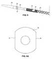
- FIG. 9is a perspective view of the distal portion of the stent delivery catheter of the invention with a portion of the outer sheath stripped away to reveal a garage member.
- FIG. 9Ais an end view of a stop member.
- FIG. 10is a planar view of a garage member.
- FIG. 11is a side view of a garage member attached to a pair of mandrels.
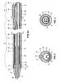
- FIG. 12Ais a side view of an expandable member in its expanded state.
- FIG. 12Bis a side view of an expandable member in its contracted state and having a plurality of stent segments thereon.
- FIG. 12Cis a side cross-section of an expandable member according to the invention.
- FIG. 13is a side view of a pusher tube.
- FIG. 13Ais a cross-sectional view of the pusher tube of FIG. 13 taken at line A-A.
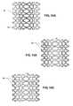
- FIGS. 14A-Bare side views of a stent segment embodiment having radiopaque markers affixed thereto.
- FIGS. 15A-Care side views of stent segment embodiments having radiopaque marker coatings applied thereto.
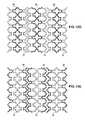
- FIGS. 15D-Eare side views of multiple stent segments in their expanded configurations having radiopaque marker coatings applied thereto.
- FIG. 16is a side view of a slider tube.
- FIG. 16Ais a cross-sectional view of the slider tube of FIG. 16 taken at line A-A.
- FIG. 17is a side view of a slider body.
- FIG. 17Ais a cross-sectional view of the slider body of FIG. 17 taken at line A-A.
- FIG. 17Bis an end view of the slider body of FIG. 17 .
- FIG. 18Ais a side view of a slider cap.
- FIG. 18Bis an end view of the slider cap of FIG. 18A .
- FIG. 19is a perspective view of a slider seal.
- Stent delivery catheter 20includes a catheter body 22 comprising an outer sheath 25 slidably disposed over an inner shaft 27 (not shown in FIG. 1 ).
- An expandable member 24preferably an inflatable balloon (shown in an inflated configuration), is mounted to inner shaft 27 and is exposed by retracting sheath 25 relative to inner shaft 27 .
- a tapered nosecone 28composed of a soft elastomeric material to reduce trauma to the vessel during advancement of the device, is mounted distally of expandable member 24 .
- a stent 30which preferably comprises a plurality of separate or separable stent segments 32 , is disposed on expandable member 24 for expansion therewith.
- a guidewire tube 34is slidably positioned through a guidewire tube exit port 35 in sheath 25 proximal to expandable member 24 .
- a guidewire 36is positioned slidably through guidewire tube 34 , expandable member 24 , and nosecone 28 and extends distally thereof.
- a handle 38is attached to a proximal end 23 of the sheath 25 .
- the handle 38performs several functions, including operating and controlling the catheter body 22 and the components included in the catheter body.
- Various embodiments of a preferred handle and additional details concerning its structure and operationare described in co-pending U.S. patent application Ser. No. 11/148,713 filed Jun. 8, 2005, U.S. Pat. Pub. No. 2006/0282150 A1), entitled “Devices and Methods for Operating and Controlling Interventional Apparatus,” which application is hereby incorporated herein by reference.
- Embodiments of another preferred handle and details concerning its structure and operationare described in co-pending U.S. application Ser. No. 10/746,466, filed Dec. 23, 2003 (U.S. Pat. No. 7,326,236), entitled “Devices and Methods For Controlling and indicating the Length of an interventional Element,” which application is also hereby incorporated herein by reference.
- the handle 38includes a housing 39 that encloses the internal components of the handle.
- the inner shaft 27is preferably fixed to the handle, while the outer sheath 25 is able to be retracted and advanced relative to the handle 38 .
- An adaptor 42is attached to the handle 38 at its proximal end, and is fluidly coupled to the inner shaft 27 in the interior of the housing of the handle 38 .
- the adaptor 42is configured to be fluidly coupled to an inflation device, which may be any commercially available balloon inflation device such as those sold under the trade name “IndeflatorTM”, available from Guidant Corp. of Santa Clara, Calif.
- the adaptoris in fluid communication with the expandable member 24 via an inflation lumen in the inner shaft 27 to enable inflation of the expandable member 24 .
- the outer sheath 25 and guidewire 36each extend through a slider assembly 50 located on the catheter body 22 at a point between its proximal and distal ends.
- the slider assembly 50is adapted for insertion into and sealing within a hemostatic valve, such as on an introducer sheath or guiding catheter, while allowing relative movement of the outer sheath 25 relative to slider assembly 50 .
- the slider assembly 50includes a slider tube 51 , a slider body 52 , and a slider cap 53 . These components are illustrated in greater detail in FIGS. 16-19 .
- FIGS. 16 and 16Ashow the slider tube 51 , which comprises an elongated cylindrical member having a first through-hole 51 a and a second through-hole 51 b .
- the first through-hole 51 ahas a size to provide a slidable passageway for the catheter body 22
- the second through-hole 51 bhas a size to provide a slidable passageway for the guidewire 34 .
- the slider tube 51is preferably formed from a polymeric material, such as PTFE, FEP, polyimide, nylon, or Pebax.
- the slider body 52is illustrated in FIGS. 17 and 17 A-B.
- the slider body 52is also an elongated member having a cylindrical section 160 and a tapered section 161 .
- the tapered section 161has an internal recess 161 a that has an interior diameter that provides a snug fit with the external surface of the slider tube 51 .
- the cylindrical section 160has an internal recess 160 a that has an interior diameter that provides a snug fit with the external surface of the slider cap 53 .
- the slider body 52also includes a first through-hole 52 a sized to allow slidable passage of the catheter body 22 , and a second through-hole 52 b sized to allow passage of the guidewire 34 .
- the slider bodyis preferably formed from a resilient, relatively incompressible material, such as polycarbonate, and has an exterior surface adapted for being clamped and sealed within a hemostasis valve, preferably being smooth and cylindrical in shape.
- the slider cap 53is a relatively short cylindrical member having a first through-hole 53 a sized to allow slidable passage of the catheter body 22 , and a second through-hole sized to allow slidable passage of the guidewire 34 .
- the slider cap 53has a size that provides a snug fit with the internal recess 160 a of the cylindrical section 160 of the slider body.
- the slider cap 53is also preferably formed of a resilient, relatively incompressible material, such as polycarbonate.
- a slider seal 54is illustrated in FIG. 19 .
- the slider sealis a short, disc-shaped member having a size adapted to fit snugly within the internal recess 160 a of the cylindrical section 160 of the slider body.
- the slider seal 54includes a first through-hole 54 a sized to allow fluidly sealed, slidable passage of the catheter body 22 , and a second through-hole 54 b sized to allow fluidly sealed, slidable passage of the guidewire 34 .
- the slider sealis preferably formed of a pliable, resilient material, such as a polymeric material or a silicone compound that is capable of providing a fluid-tight seal with the sheath and guidewire while allowing slidable movement thereof.
- the slider assembly 50is constructed by installing the proximal end of the slider tube 51 into the internal recess 161 a of the tapered portion 161 of the slider body, taking care to align the first and second through-holes of each member appropriately.
- the slider seal 54is installed in the internal recess 160 a of the cylindrical portion 160 of the slider body, and the slider cap 53 is placed over the slider seal 54 within the internal recess 160 a , again taking care to ensure that the first and second through-holes of each component are properly aligned.
- the componentsare then bonded together by heating or by use of adhesives or other suitable means.
- the completed slider assembly 50is then placed over the catheter body 22 and the guidewire 34 as shown in FIG. 1 .
- FIGS. 2A-2B , 3 and 4show a distal portion of the stent delivery catheter in cross-section
- sheath 25may be extended up to nosecone 28 to fully surround expandable member 24 and stent segments 32 .
- a garage 55is attached to the outer sheath 25 at the distal end 57 of the sheath.
- the garage 55is a generally cylindrical member having a relatively high circumferential strength such that it is able to prevent the expandable member 24 from inflating when the garage is extended over the inflatable member 24 .
- the garage 55preferably has a length at least as long as one of the stent segments 32 carried by the catheter, but preferably less than the combined length of two such stent segments.
- a radiopaque marker 56is preferably formed integrally with or attached to the distal end of the garage 55 to facilitate visualization of the position of the sheath 25 using fluoroscopy.
- the radiopaque marker 56may have an axial length selected to provide a visual reference for determining the appropriate distance for stent segment separation, e.g., 2-4 mm, as described below.
- the outer sheath 25further includes a valve member 58 within the garage 55 preferably spaced proximally from the distal end 57 a distance equal to, slightly larger than, or slightly smaller than the length of one of the stent segments 32 .
- each stent segment 32has a length of about 4 mm
- the valve member 53is located approximately 5 mm from the distal end 57 of the sheath or the distal end of the garage member 55 .
- the valve member 58may be spaced from the distal end 57 a distance equal to about 1 ⁇ 4-3 ⁇ 4 of the length of one stent segment 32 , more preferably one-half the length of one stent segment 32 .
- Valve member 58preferably comprises a necked-down circumferential waist or inwardly extending ring-shaped flange 60 configured to frictionally engage stent segments 32 and thereby restrict the sliding movement of stent segments 32 distally relative to sheath 25 .
- Flange 60may be a polymeric or metallic material integrally formed with sheath 25 or, preferably, with the garage 55 , or a separate annular member bonded or otherwise mounted to the interior of the sheath 25 or the garage 55 .
- the geometry of flange 60may be toroidal with circular cross-section (like an O-ring) or it may have another cross-sectional shape such as triangular, trapezoidal, or pyramidal.
- flange 60is a polymer such as silicone or urethane sufficiently soft, compliant, and resilient to provide frictional engagement with stent segments 32 without damaging the stent segment or any coating deposited thereon.
- Valve member 58will extend radially inwardly a sufficient distance to engage the exterior of stent segments 32 with sufficient force to allow the line of stent segments 32 remaining within sheath 25 to be retracted proximally with sheath 25 so as to create spacing relative to those stent segments disposed distally of sheath 25 for deployment.
- valve member 58should not exert so much force that it removes or damages the coating on the exterior surface of stent segments 32 as sheath 25 is retracted relative to the stent segments to expose a desired number of stem segments 32 .
- stem segments 32have an outer diameter of about 0.040-0.050 in. (including coating) and sheath 25 and garage 55 have inner diameter 0.041-0.051 in. so as to provide clearance of about 0.001 in. with stein segments 32 .
- Valve member 58has a preferred inner diameter about 0.003-0.008 in. less than that of garage 55 , or about 0.033-0.048′′, so as to provide an interference fit with stent segments 32 .
- Valve member 58will preferably exert a force of about 0.5-5 lbs. on a stent segment 32 positioned within it.
- Various embodiments of valve member 58are described in copending application Ser. No. 10/412,714, Filed Apr. 10, 2003 (U.S. Pat. No. 7,137,993), which is incorporated herein by reference.
- FIGS. 9-11illustrate the garage 55 , the radiopaque marker 56 , and the valve member 58 in greater detail.
- the garage 55is a cylindrical member that is preferably mounted to the distal end of the outer sheath 25 .
- FIG. 9illustrates the garage 55 as it is oriented surrounding the stent segments 32 aligned over the inner shaft. The distal portion of the outer sheath 25 is shown stripped away in FIG. 9 to reveal the orientation of the garage 55 .
- the cylindrical garage 55is preferably formed of a metallic, polymeric, or other material and in a geometry to provide high radial strength and high axial flexibility. Superelastic alloys are preferred materials.
- a preferred garage materialis Nitinol.
- the structure of the garage 55is illustrated in FIG. 10 , in which the garage 55 is shown in a planar form for clarity.
- the garage 55is preferably laser cut from a tube, but may also be cut, stamped, or otherwise formed from a sheet of material.
- a number of cut-outs or windows 59are preferably formed in the body of the garage to increase its axial flexibility.
- the garage 55is constructed in a manner and of materials that allow it to bend about a transverse axis.
- the illustrated embodimentincludes a preferred form.
- the distal end 55 a of the garage 55is provided with no cut-outs in order to provide the greatest radial strength at the distal end of the sheath, where the restraining force against the expandable member 24 is the greatest.
- a pair of first cut-outs 59 a having oval or rectangular shapeare formed a short distance from the distal end 55 a of the garage, the pair of first cut-outs 59 a being aligned circumferentially around the periphery of the garage.
- a series of narrow second cut-outs 59 b having a linear or slot-like shapeare formed over the central portion of the body of the garage 55 .
- the second cut-outs 59 bare provided in a staggered formation to provide greater axial flexibility over the central portion of the garage.
- a series of third cut-outs 59 care located just proximally of the central portion of the garage.
- the third cut-outs 59 care of a similar size and shape to the first cut-outs 59 a , but are circumferentially staggered from the first cut-outs 59 a .
- a series of fourth rectangular or oval-shaped cut-outs 59 dare located just proximally of the third cut-outs, and are both narrower and shorter than the third cut-outs 59 c .
- a series of fifth cut-outs 59 e having a hexagonal shapeare provided near the proximal end 55 b of the garage.
- Each of the fifth cut-outs 59 eis substantially wider (i.e., greater longitudinal length) than the other cut-outs 59 a - d .
- the position of the fifth cut-outscorresponds with the location of the valve member 58 .
- the garage 55is shown supported on a proximal mandrel 150 and a distal mandrel 152 to facilitate attachment of the valve member 58 and sheath 25 thereto.
- the proximal mandrelis provided with an indentation or concavity adapted to receive and retain the valve member 58 in place for the purpose of attaching the valve member 58 to the garage 55 and outer sheath 25 .
- the radiopaque marker 56may be placed over the distal end 55 a of the garage 55 .
- the outer sheath 25is attached to the proximal end 55 b of garage 55 , preferably by placing a piece of shrink tubing over the garage and distal end of the outer sheath and heating the assembly.
- the garage 55is thereby covered with a polymer material about its exterior.
- various other attachment techniquesmay be used including heat treatment, adhesives, or other methods known to those skilled in the art.
- the sheath 25has a distal extremity 62 configured to surround expandable member 24 and stent segments 32 disposed thereon when in an unexpanded configuration.
- Distal extremity 62extends proximally to a junction 63 , preferably aligned with the location of guidewire tube exit port 35 , where distal extremity 62 is joined to a proximal extremity 64 that extends proximally to handle 38 (see FIG. 1 ).
- distal extremity 62has a length of about 15-35 cm and proximal extremity 64 as a length of about 100-125 cm.
- Proximal extremity 64may be constructed of a variety of biocompatible polymers, metals, or polymer/metal composites, preferably being stainless steel or Nitinol.
- Distal extremity 62may be a polymer such as PTFE, FEP, polyimide, nylon, or Pebax, or combinations of any of these materials.
- the distal extremity 62comprises a composite of nylon, PTFE, and polyimide.
- the distal extremityis preferably reinforced with a metallic or polymeric braid to resist radial expansion when expandable member 24 is expanded.
- Sheath 25may further have a liner surrounding its interior of low friction material such as PTFE to facilitate relative motion of sheath 25 , stent segments 32 , and pusher tube 86 .
- proximal extremity 64has a smaller transverse dimension than distal extremity 62 to accommodate the added width of guidewire tube 34 within the vessel lumen, as well as to maximize flexibility and minimize profile.
- distal extremity 62is a tubular member having a first outer diameter, preferably about 1.0-1.5 mm
- proximal extremity 64is a tubular member having a second, smaller outer diameter, preferably about 0.7-1.0 mm.
- a proximally-facing crescent-shaped opening 65is formed between the two tubular members that creates guidewire tube exit port 35 . Excess space within crescent-shaped opening 65 may be filled with a filler material such as adhesive or a polymeric material (e.g., Pebax).
- a holeis formed in the sidewall of distal extremity 62 or proximal extremity 64 to create guidewire tube exit port 35 .
- the wall of sheath 25 adjacent to guidewire tube 34is flattened or collapsible inwardly thereby reducing the transverse dimension of sheath 25 to accommodate the width of guidewire tube 34 .
- Guidewire tube 34is slidably positioned through guidewire tube exit port 35 .
- the guidewire tube exit port 35may be configured to provide a total or partial fluid seal around the periphery of guidewire tube 34 to limit blood flow into the interior of sheath 25 and to limit leakage of saline (or other flushing fluid) out of sheath 25 . This may be accomplished by sizing guidewire tube exit port 35 appropriately so as to form a fairly tight frictional seal around guidewire tube 34 while still allowing the sliding motion thereof relative to sheath 25 .
- an annular sealing ringmay be mounted in guidewire tube exit port 35 to provide the desired seal.
- the guidewire tube exit port 35is not totally fluid sealed, so as to provide a slight leakage or fluid flow to provide the ability to flush the distal extremity 62 of the catheter.
- Guidewire tube exit port 35will be positioned to provide optimal tracking of stent delivery catheter 20 through the vasculature and maximizing the ease with which the catheter can be inserted onto and removed from a guidewire to facilitate catheter exchanges.
- guidewire tube exit port 35will be positioned at a location proximal to expandable member 24 when sheath 25 is extended fully distally up to nosecone 28 , but a distance of no more than one-half the length of sheath 25 from distal end 57 .
- guidewire tube exit port 35is spaced proximally a distance of about 20-35 cm from the distal end 57 of sheath 25 .
- Guidewire tube 34should extend proximally from guidewire tube exit port 35 a distance at least as long as the longest possible stent that may be deployed, e.g., 30-200 mm depending upon the application, to allow for retraction of sheath 25 that distance while retaining a portion of guidewire tube 34 external to sheath 25 .
- the guidewire tube 34extends proximally a distance of about 35 to about 70 mm from the guidewire tube exit port 35 when sheath 25 is in a fully distal position, with the proximal end thereof disposed a distance of about 23-50 cm from the distal tip of nosecone 28 .
- guidewire tube 34will preferably be positioned so as to be within the guiding catheter when expandable member 24 is positioned at the target site for stent deployment.
- Guidewire tube 34is preferably a highly flexible polymer such as PTFE, FEP, polyimide, or Pebax, and may optionally have a metal or polymer braid or fiber embedded in it to increase kink-resistance and tensile strength.
- Inner shaft 27forms an inflation lumen 66 that is in communication with interior of expandable member 24 .
- the inner shaft 27may be formed of a polymer material such as PTFE, FEP, polyimide, or Pebax, or the inner shaft 27 may be a metal such as stainless steel or Nitinol.
- Expandable member 24has an expandable balloon member 70 that is joined to a non-expandable tubular leg 72 .
- Expandable balloon member 70is a semi-compliant polymer such as Pebax, polyurethane, or Nylon. Non-compliant, fully elastic, or other materials such as PTFE may also be used.
- the compliance of the balloon memberallows the expanded diameter of balloon member 70 to be adjusted by selecting the appropriate inflation pressure delivered thereto, thereby allowing customization of the deployed diameter of stent segments 32 .
- balloon member 70may be inflated to a pressure of between about 5 and about 12 atmospheres, allowing the deployed stent diameter to be adjusted from about 2.0 mm to 4.0 mm.
- Tubular leg 72is preferably a polymer such as polyimide, PTFE, FEP, polyurethane, or Pebax and may optionally be reinforced with a metal or polymer braid or metal or polymer fibers.
- Tubular leg 72has an open proximal end 74 through which guidewire tube 34 extends. Proximal end 74 of tubular leg 72 is fixed to distal end 68 of inner shaft 27 and to guidewire tube 34 , forming a fluid-tight seal.
- Guidewire tube 34passes through the interior of balloon member 70 and is mounted to nosecone 28 , thereby providing a passage through the distal portion of catheter body 22 through which guidewire 36 may pass.
- Balloon member 70has a distal end 76 that extends over an annular stop 78 , which is mounted to the distal end of guidewire tube 34 and/or nosecone 28 .
- Distal end 76 of balloon member 70may be bonded to stop 78 , guidewire tube 34 , and/or nosecone 28 .
- the stop 78has a size and shape selected to engage stent segment 32 and provide a stop against which stent segments 32 can be located in the ideal deployment position without being pushed beyond the distal end of balloon member 70 . Additional details concerning stent stops suitable for use in the devices and methods described herein are disclosed in U.S.
- the stop 78has a partial cylindrical shape, rather than a full cylindrical shape, as a relief to reduce interference with garage 55 .
- FIGS. 9 and 9Aillustrate the stop 78 having a flat portion 81 formed on the opposed lateral surfaces of the stop 78 .
- a similar flat portionmay be formed on the upper and lower sides of the stop 78 .
- the provision of flat portions on the stop 78allows the stop 78 to limit distal movement of the stent segments 32 , while reducing interference between stop 78 and the interior of garage 55 .
- annular base member 80is mounted to guidewire tube 34 and has a diameter selected to urge balloon member 70 against stent segments 32 in their unexpanded configuration, thereby providing frictional engagement with stent segments 32 . This helps to limit unintended sliding movement of stent segments 32 on balloon member 70 .
- Base member 80may be made of a soft elastomer, foam, or other compressible material.
- An additional option or alternative structure for limiting unintended sliding or movement of the stent segmentsis the provision on the distal exterior portion of the expandable member 24 of a layer of material 84 having a high coefficient of friction so as to frictionally engage the stent segments 32 . See FIGS. 12A-C .
- a layer of a polymeric material 84such as polyurethane, will prevent the stent segments 32 from sliding off the distal end of the balloon, and will cause the stent segments 32 to stop in the desired location near the distal end of the expandable member 24 .
- the layer of material 84is preferably formed over the entire circumference of the distal end of the expandable member 24 , as shown in the Figures, but may alternatively be placed only at spaced intervals around the periphery.
- the material layer 84is preferably formed of elastomeric materials and in a manner that allows it to expand and contract as the expandable member 24 expands and contracts.
- the material layer 84may be applied by dipping the expandable member 24 in a liquid polymer, by spraying, or by attaching a sheet or tube of material over the expandable member 24 by adhesive or heat treatment.
- Material layer 84may be of equal thickness along it length, or the thickness of the material layer 84 may gradually increase in the distal direction to provide gradually increasing interference with stent segments 32 .
- Material layer 84may have an outer surface at the same height as the outer surface of expandable member 24 to provide a smooth transition therebetween, or material layer 84 may be of greater height to provide a step that enhances engagement with stent segments 32 .
- expandable member 24is molded with a circumferential channel, stepped geometry, and/or with reduced wall thickness near its distal end so as to have a smaller outer diameter in the region where the material layer 84 is to be applied to accommodate the thickness of material layer 84 .
- the outer wall of the expandable member 24 and material layer 84will be smooth and continuous without an abrupt change in elevation, allowing stent segments 32 to slide smoothly from the expandable member 24 to the material layer 84 .
- expandable member 24 and/or material layer 84may have an outer diameter or wall thickness that is stepped outwardly or that gradually increases in the distal direction so as to increase the frictional resistance with stent segments 32 .
- material layer 84may have surface features such as bumps, ridges, projections, or scales to increase friction against stent segments 32 .
- Annular radiopaque markers 82may be mounted to the guidewire tube 34 , facilitating visualization of the location of balloon member 70 with fluoroscopy and enabling appropriate positioning of stent segments 32 on balloon member 70 .
- the radiopaque markers 82are preferably located at regular intervals along the length of the guidewire tube 34 .
- the radiopaque markers 82are spaced at intervals that are related to the length of individual stent segments 32 , such as being at intervals equal to the stent segment lengths, one-half of stent segment length, double stent segment length, or the like.
- the distance between the distal ends of adjacent markers 82are provided equal to the stent segment lengths, one-half of stent segments length, double stent segment length, or the like. Locating multiple radiopaque markers 82 on the guidewire tube 34 at regularly spaced intervals provides a visual reference for determining the location and number of stent segments 32 on expandable member 24 under fluoroscopy. Further, the length of expandable member 24 and stent segments 32 exposed during retraction of sheath 25 may be determined under fluoroscopy by observing the position of marker 56 on garage member 55 relative to marker(s) 82 on guidewire tube 34 .
- markers 82 at or near the distal end of balloon member 70may be used, or markers may be placed at both the distal end and proximal end of the base member 80 , or markers may be placed at other locations on nosecone 28 , guidewire tube 34 , or inner shaft 27 .
- markersmay be made of various radiopaque materials such as platinum/iridium, tantalum, gold, and other materials.
- Stent segments 32are slidably positioned over balloon member 70 . Depending upon the number of stent segments 32 loaded in stent delivery catheter 20 , stent segments 32 may be positioned over both balloon member 70 and tubular leg 72 . In an exemplary embodiment, each stent segment is about 2-20 mm in length, more preferably 2-8 mm in length, and 3-50 stent segments may be positioned end-to-end in a line over balloon member 70 and tubular leg 72 . Stent segments 32 preferably are in direct contact with each other, but alternatively separate spacing elements may be disposed between adjacent stent segments, the spacing elements being movable with the stent segments along balloon member 70 .
- spacing elementsmay be plastically deformable or self-expanding so as to be deployable with stent segments 32 into the vessel, but alternatively could be configured to remain on balloon member 70 following stent deployment; for example, such spacing elements could comprise elastic rings which elastically expand with balloon member 70 and resiliently return to their unexpanded shape when balloon member 70 is deflated. The spacing elements could be pushed to the distal end of balloon member 70 against stop 78 as additional stent segments 32 are advanced distally.
- Stent segments 32are preferably a malleable metal so as to be plastically deformable by expandable member 24 as they are expanded to the desired diameter in the vessel.
- stent segments 32may be formed of an elastic or super elastic shape memory material such as Nitinol so as to self-expand upon release into the vessel by retraction of sheath 25 .
- Stent segments 32may also be composed of polymers or other suitable biocompatible materials including bioabsorbable or bioerodable materials.
- expandable member 24may be eliminated or may be used for predilatation of a lesion prior to stent deployment or for augmenting the expansion of the self-expanding stent segments.
- stent segments 32are coated with a drug that inhibits restenosis, such as Rapamycin, Paclitaxel, Biolimus A9 (available from BioSensors International), analogs, prodrugs, or derivatives of the foregoing, or other suitable agent, preferably carried in a durable or bioerodable polymeric or other suitable carrier material.
- stent segments 32may be coated with other types of drugs and therapeutic materials such as antibiotics, thrombolytics, anti-thrombotics, anti-inflammatories, cytotoxic agents, antiproliferative agents, vasodilators, gene therapy agents, radioactive agents, immunosuppressants, and chemotherapeutics.
- stent segments 32may include apertures, holes, channels, pores, or other features in which such materials may be deposited.
- Methods for coating stent segments 32are described in the foregoing published patent application.
- Various other coating methods known in the artmay also be used, including syringe application, spraying, dipping, inkjet printing-type technology, and the like.
- Stent segments 32may have a variety of configurations, including those described in copending application Ser. No. 10/738,666, filed Dec. 16, 2003 (U.S. Pat. Pub. No. 2004/0186551 A1), which is incorporated herein by reference. Other preferred stent configurations are described below. Stent segments 32 are preferably completely separate from one another without any interconnections, but alternatively may have couplings between two or more adjacent segments which permit flexion between the segments. As a further alternative, one or more adjacent stent segments may be connected by separable or frangible couplings that are separated prior to or upon deployment, as described in co-pending application Ser. No. 10/306,813, filed Nov. 27, 2002 (U.S. Pat. Pub. No. 2003/0135266 A1), which is incorporated herein by reference.
- a pusher tube 86is slidably disposed over inner shaft 27 .
- the structure of the pusher tube 86is illustrated in FIG. 13 , and its location within the catheter body 22 is best shown in FIGS. 2A-B .
- the pusher tube 86contains three primary sections, a distal extension 88 , a ribbon portion 89 , and a proximal portion 90 .
- the proximal portion 90extends from the handle 38 over the inner shaft 27 and to the ribbon portion 89 .
- the proximal portion 90is preferably formed of a tubular material to provide high column strength but adequate flexibility to extend through the vasculature from an access site to the coronary ostia or other target vascular region.
- a preferred materialis stainless steel hypotube.
- the ribbon portion 89 of the pusher tubecorresponds with the location of the guidewire exit port 35 on the outer sheath 25 .
- the ribbon portion 89is formed of a partial-tube, see, e.g., FIG. 13A , in order to provide an opening to allow the guidewire tube 34 to pass through to the exit port 35 .
- the proximal portion of the ribbon portion 89is formed out of the same tubular material that makes up the proximal portion 90 of the pusher tube, e.g., stainless steel hypotube.
- the proximal portion of the ribbon portion 89is joined to the distal portion of the ribbon 89 , such as by a weld 91 or the ribbon portion and proximal portion may be formed from the same hypotube which is laser cut in the appropriate geometry.
- the distal extension 88is preferably formed of a slotted tube of rigid material, such as stainless steel or Nitinol.
- the slotted tube making up the distal extension 88includes a number of cylindrical rings 92 interconnected by longitudinal connectors 93 , thereby defining a plurality of transverse slots 97 arranged in pairs along the length of the distal extension. Each pair of slots is disposed opposite one another on distal extension 88 , thus defining a pair of opposing, longitudinal connectors 93 .
- the longitudinal connectors 93are flexible so as to be capable of bending around a transverse axis.
- Each pair of transverse slots 97is oriented at 90 degrees relative to the adjacent pair of slots 97 , so that the pairs of longitudinal connectors 93 alternate between those oriented vertically and those oriented horizontally. This allows distal extension 88 to bend about either a horizontal and vertical transverse axes, thus providing a high degree of flexibility.
- the pairs of transverse slots 97could be oriented at various angles relative to adjacent pairs to provide flexibility about more than two axes.
- the slots provided in the slotted tubeallows the distal extension 88 to be more axially flexible than it would be without the slots, while still retaining high column strength.
- transverse slots 97 and cylindrical rings 92that each have a width that is approximately the same as the length of a stent segment 32 .
- the transverse slots 97 and cylindrical rings 92may be spaced apart by a known fraction or multiple of the stent segment length.
- a detent mechanismmay be provided on the interior surface of the sheath 25 , with one or more detents that releasably engage the cylindrical rings 92 formed in the distal extension 88 to provide a tactile feedback based upon the distance that the outer sheath 25 is retracted relative to pusher tube 86 .
- a nesting tip 94is formed on the distal end of the distal extension 88 .
- the nesting tippreferably includes a plurality of fingers shaped and oriented to engage and interleave with the proximal end of the most proximal stent segment 32 .
- stent segments 32preferably have axial extensions or projections on each end which interleave with those on the adjacent stent segment.
- Tip 94 of pusher tube 86preferably has a geometry with axial projections similar to or complementary to those of stent segments 32 so as to interleave therewith.
- the proximal portion 90 of the pusher tubehas a diameter that is smaller than the diameter of the distal extension 88 .
- the stainless steel hypotube material making up the proximal portion 90 of the pusher tube and part of the ribbon portion 89may have a first diameter, while the slotted tube making up the distal extension 88 and the distal portion of the ribbon 89 may have a second, larger diameter.
- the slotted tube and the hypotubeare preferably joined by a weld 91 formed in the ribbon portion 89 .
- the pusher tube 86extends longitudinally within the outer sheath 25 and over the inner shaft 27 through most of the length of the catheter body 22 .
- the distal extension 88is slidable over the tubular leg 72 and engages the stent segment 32 at the proximal end of the line of stent segments 32 .
- the pusher tube 86is coupled to an actuator associated with the handle 38 (see FIG. 1 ).
- the pusher tube 86can be advanced distally relative to inner shaft 27 to urge the stent segments 32 distally over the expandable member 24 (or, alternatively, the pusher tube 86 may be held in position while retracting the expandable member 24 relative to stent segments 32 ) until the stent segments engage the stop 78 .
- the pusher tube 86can be used to hold the stent segments 32 in place on the expandable member 24 while the sheath 25 is retracted to expose a desired number of stent segments 32 , as shown in FIG. 2B .
- proximal portion 90 , ribbon portion 89 , and distal extension 88 of the pusher tubeare preferably constructed of stainless steel, but they may alternatively be constructed of a variety of biocompatible polymers, metals, polymer/metal composites, alloys, or the like.
- expandable member 24is allowed to expand when inflation fluid is delivered through inflation lumen 66 , thereby expanding a desired number of stent segments 32 exposed distally of sheath 25 .
- the remaining portion of expandable member 24 and the remaining stent segments 32 within sheath 25are constrained from expansion by sheath 25 .
- FIG. 2Bfurther illustrates that when sheath 25 is retracted relative to expandable member 24 , guidewire tube exit port 35 becomes further away from the point at which guidewire 36 exits the proximal end 74 of tubular leg 72 , increasing the distance that guidewire 36 must pass within the interior of sheath 25 .
- guidewire tube 34provides a smooth and continuous passage from the tubular leg 72 through guidewire tube exit port 35 , eliminating any problems that might result from changing the alignment of the two.
- the stent delivery cathetermay carry a large number of stent segments 32 and sheath 25 may be retracted a substantial distance relative to expandable member 24 , resulting in substantial misalignment of guidewire tube exit port 35 relative to tubular leg 72 .
- fluoroscopyis used to visualize the stent segments 32 relative to the markers 82 located on the inner shaft 27 .
- the usercan see the extent of retraction of the sheath 25 relative to the expandable member 24 and view the location of the exposed stent segments 32 relative to the sheath 25 .
- Visualization of the stent segments 32is further enhanced with the use of radiopaque markers and/or materials in or on the stent segments themselves.
- Markers of radiopaque materialsmay be applied to the exterior of stent segments 32 , e.g., by applying a metal such as gold, platinum, a radiopaque polymer, or other suitable coating or mark on all or a portion of the stent segments. Examples of such markers are illustrated in FIGS. 14A-B . In those Figures, radiopaque markers 95 are attached to a plurality of circular openings formed in the body of the stent segment 32 . Six such markers are formed in a circumferentially aligned pattern in the FIG. 14A example, while three markers are formed in another circumferentially aligned pattern in the FIG. 14B example.
- the markersmay be discs, buttons, or other members that are welded in place, or they may be provided as rivets or rivet-type members that are installed in a sized hole or eyelet.
- stent segments 32may include a radiopaque cladding or coating or may be composed of radiopaque materials such as L-605 cobalt chromium (ASTM F90), other suitable alloys containing radiopaque elements, or multilayered materials having radiopaque layers. See, for example, FIGS. 15A-C , where three patterns of radiopaque coatings are illustrated.
- a coating 96 of radiopaque materialis provided in a broad circumferential center stripe on the stent segment 32 .
- FIGS. 15Aa coating 96 of radiopaque material is provided in a broad circumferential center stripe on the stent segment 32 .
- stent segments 32may have a geometry conducive to fluoroscopic visualization, such as having struts of greater thickness, sections of higher density, or overlapping struts.
- the radiopaque markersare configured so as to provide an indication of the number, location, and/or relative spacing of each stent segment 32 when deployed end-to-end in a line in a vessel or other body lumen. This allows the operator to determine how many stent segments 32 have been deployed at a vascular site, and the spacing between adjacent stent segments 32 .
- the radiopaque markersallow the operator to visualize with fluoroscopy the divisions between adjacent stent segments 32 by observing radiopaque markers on the ends and/or a middle portions of each stent segment 32 . For example, in the embodiment of FIG. 15D , the operator may visualize a central stripe on each segment to allow an accounting of the number and location of deployed segments 32 .
- FIG. 15Dthe embodiments of FIG.
- the operatormay visualize two adjacent radiopaque stripes where two segment ends are disposed side-by-side. If the segments are close together, the operator sees a single wide stripe, while if the segments are separated by a gap, the operator may see two parallel stripes, thus providing an indication of the segment spacing as well as number.
- stent segments 32Some of the possible materials that may be used in stent segments 32 include (by ASTM number):
- FIGS. 5A-Billustrate a portion of a first embodiment of a stent segment 32 .
- the Figuresillustrate a portion of the stent segment 32 in a planar shape for clarity.
- the stent segment 32includes two parallel rows 98 A, 98 B of I-shaped cells 100 formed into a cylindrical shape around an axial axis A.
- Each cell 100includes upper and lower axial slots 102 and a connecting circumferential slot 104 .
- the upper and lower slots 102are bounded by upper axial struts 106 , lower axial struts 107 , curved outer ends 108 and curved inner ends 110 .
- Each circumferential slot 104is bounded by an outer circumferential strut 109 and an inner circumferential strut 111 .
- Each I-shaped cell 100is connected to the adjacent I-shaped cell 100 in the same row 98 A or 98 B by a circumferential connecting strut 113 . All or a portion of cells 100 in row 98 A merge or join with cells 100 in row 98 B at the inner ends 110 , which are integrally formed with the inner ends 110 of the adjacent cells 100 .
- a spacing member 112extends outwardly in the axial direction from a selected number of outer circumferential struts 109 and/or connecting struts 113 .
- Spacing member 112preferably itself forms a subcell 114 in its interior, but alternatively may be solid without any cell or opening therein.
- subcell 114preferably communicates with I-shaped cell 100 .
- Spacing members 112are configured to engage the curved outer ends 108 of an adjacent stent segment 32 so as to maintain appropriate spacing between adjacent stent segments.
- spacing members 112have outer ends 116 with two spaced-apart protrusions 118 that provide a cradle-like structure to index and stabilize the curved outer end 108 of the adjacent stent segment.
- spacing members 112have an axial length of at least about 10%, more preferably at least about 25%, of the long dimension L of I-shaped cells 100 , so that the I-shaped cells 100 of adjacent stent segments are spaced apart at least that distance. Because spacing members 112 experience little or no axial shortening during expansion of stent segments 32 , this minimum spacing between stent segments is maintained both in the unexpanded and expanded configurations.
- FIG. 5Bshows stent segment 32 of FIG. 5A in an expanded configuration. It may be seen that cells 100 are expanded so that upper and lower slots 102 are diamond shaped with circumferential slots 104 remaining basically unchanged. This results in some axial shortening of the stent segment, thereby increasing the spacing between adjacent stent segments.
- the stent geometryis optimized by balancing the amount of axial shortening and associated inter-segment spacing, the desired degree of vessel wall coverage, the desired metal density, and other factors. Because the stent is comprised of multiple unconnected stent segments 32 , any desired number from 2 up to 10 or more stent segments may be deployed simultaneously to treat lesions of any length. Further, because such segments are unconnected to each other, the deployed stent structure is highly flexible and capable of deployment in long lesions having curves and other complex shapes.
- circumferential slots 104provide a pathway through which vessel side branches can be accessed for catheter interventions.
- a balloon dilatation cathetermay be positioned through circumferential slot 104 and expanded. This deforms circumferential struts 109 , 111 axially outward, thereby expanding circumferential slot 104 and further expanding upper and lower slots 102 , as shown in phantom in FIG. 5B .
- Thisprovides a relatively large opening 120 through which a catheter may be inserted through stent segment 32 and into the side branch for placing stents, performing angioplasty, or carrying out other interventions.
- FIGS. 6A-6Billustrate a second embodiment of a stent segment 32 according to the invention.
- a portion of stent segment 32is shown in a planar shape for clarity.
- stent segment 32comprises two parallel rows 122 A, 122 B of I-shaped cells 124 formed into a cylindrical shape around axial axis A.
- Cells 124have upper and lower axial slots 126 and a connecting circumferential slot 128 .
- Upper and lower slots 126are bounded by upper axial struts 130 , lower axial struts 132 , curved outer ends 134 , and curved inner ends 136 .
- Circumferential slots 128are bounded by outer circumferential strut 138 and inner circumferential strut 140 .
- Each I-shaped cell 124is connected to the adjacent I-shaped cell 124 in the same row 122 by a circumferential connecting strut 142 .
- Row 122 Ais connected to row 122 B by the merger or joining of curved inner ends 136 of at least one (and preferably three) of upper and lower slots 126 in each cell 124 .
- the embodiment of FIG. 6Aincludes a bulge 144 in upper and lower axial struts 130 , 132 extending circumferentially outwardly from axial slots 126 . These give axial slots 126 an arrowhead or cross shape at their inner and outer ends.
- the bulge 144 in each upper axial strut 130extends toward the bulge 144 in a lower axial strut 132 in the same cell 100 or in an adjacent cell 100 , thus creating a concave abutment 146 in the space between each axial slot 126 .
- Concave abutments 146are configured to receive and engage curved outer ends 134 of cells 124 in the adjacent stent segment, thereby maintaining spacing between the stent segments.
- the axial location of bulges 144 along upper and lower axial struts 130 , 132may be selected to provide the desired degree of inter-segment spacing.
- FIG. 6Bshows two stent segments 32 of FIG. 6A in an expanded condition. It may be seen that axial slots 124 are deformed into a circumferentially widened modified diamond shape with bulges 144 on the now diagonal upper and lower axial struts 130 , 132 . Circumferential slots 128 are generally the same size and shape as in the unexpanded configuration. Bulges 144 have been pulled away from each other to some extent, but still provide a concave abutment 146 to maintain a minimum degree of spacing between adjacent stent segments. As in the earlier embodiment, some axial shortening of each segment occurs upon expansion and stent geometry can be optimized to provide the ideal intersegment spacing.
- FIGS. 6A-6Bretains the feature described above with respect to FIGS. 5A-5B to enable access to vessel side branches blocked by stent segment 32 .
- a dilatation cathetermay be inserted into circumferential slot 128 and expanded to provide an enlarged opening through which a side branch may be entered.
- FIGS. 7A-7Ethe use of the stent delivery catheter of the invention will be described. While the invention will be described in the context of coronary artery treatment, it should be understood that the invention is useful in any of a variety of blood vessels and other body lumens in which stents are deployed, including the carotid, femoral, iliac and other arteries, as well as veins and other fluid-carrying vessels.
- a guiding catheter(not shown) is first inserted into a peripheral artery such as the femoral and advanced to the ostium of the target coronary artery.
- a guidewire GWis then inserted through the guiding catheter into the coronary artery A where lesion L is to be treated.
- stent delivery catheter 20is slidably advanced over guidewire GW and through the guiding catheter into the coronary artery A.
- Slider assembly 50is positioned within the hemostasis valve at the proximal end of the guiding catheter, which is then tightened to provide a hemostatic seal with the exterior of the slider body 52 .
- Stent delivery catheter 20is positioned through a lesion L to be treated such that nosecone 28 is distal to lesion L. During this positioning, sheath 25 is positioned distally up to nosecone 28 so as to surround expandable member 24 and all of the stent segments 32 thereon.
- lesion Lmay be pre-dilated prior to stent deployment. Pre-dilation may be performed prior to introduction of stent delivery catheter 20 by inserting an angioplasty catheter over guidewire GW and dilating lesion L. Alternatively, stent delivery catheter 20 may be used for pre-dilation by retracting sheath 25 along with stent segments 32 to expose an extremity of expandable member 24 long enough to extend through the entire lesion. This may be done while delivery catheter 20 is positioned proximally of lesion L or with expandable member 24 extending through lesion L.
- Fluoroscopyenables the user to visualize the extent of sheath retraction relative to lesion L by observing the position of marker 56 on the garage 55 contained at the distal end of the sheath 25 relative to the markers 82 formed on the guidewire tube 34 beneath the expandable member 24 .
- forceis released from pusher tube 86 and valve member 58 engages and draws the stent segments proximally with sheath 25 .
- the pusher tube 86is retracted along with the outer sheath 25 by use of an actuator provided on the handle 38 .
- expandable member 24With the appropriate length of expandable member 24 exposed, expandable member 24 is positioned within lesion L and inflation fluid is introduced through inflation lumen 66 to inflate expandable member 24 distally of sheath 25 and thereby dilate lesion L. Expandable member 24 is then deflated and retracted within sheath 25 while maintaining force on pusher tube 86 so that stent segments 32 are positioned up to the distal end of expandable member 24 , surrounded by sheath 25 .
- stent delivery catheter 20is repositioned in artery A so that nosecone 28 is distal to lesion L as shown in FIG. 7A .
- Sheath 25is then retracted as in FIG. 7B to expose the appropriate number of stent segments 32 to cover lesion L.
- fluoroscopycan be used to visualize the position of sheath 25 by observing marker 56 thereon relative to marker 82 within expandable member 24 .
- forceis maintained against pusher tube 86 so that stent segments 32 remain positioned up to the distal end of expandable member 24 .
- sheath 25moves proximally relative to guidewire tube 34 , which slides through guidewire tube exit port 35 .
- guidewire tube 34provides a smooth and continuous passage for guidewire GW so that stent delivery catheter slides easily over guidewire GW.
- stent segments 32With the desired number of stent segments 32 exposed distally of sheath 25 , it is preferable to create some spacing between the stent segments to be deployed and those remaining enclosed within the sheath 25 . This reduces the risk of dislodging or partially expanding the distal-most stent segment 32 within sheath 25 when expandable member 24 is inflated. Such spacing is created, as shown in FIG. 7C , by releasing force against pusher tube 86 and retracting both the pusher tube 86 and the sheath 25 a short distance simultaneously. The engagement of valve member 58 with stent segments 32 moves those stent segments 32 within sheath 25 away from those stent segments 32 distal to sheath 25 .
- the length of this spacingis preferably equal to the length of about 1 ⁇ 2-1 stent segment, e.g., in one embodiment about 2-4 mm.
- Expandable member 24is then inflated by delivering inflation fluid through inflation lumen 66 , as shown in FIG. 7D .
- the exposed distal portion of expandable member 24expands so as to expand stent segments 32 thereon into engagement with lesion L. If predilatation was not performed, lesion L may be dilated during the deployment of stent segments 32 by appropriate expansion of expandable member 24 .
- Sheath 25constrains the expansion of the proximal portion of expandable member 24 and those stent segments 32 within sheath 25 .
- Expandable member 24is then deflated, leaving stent segments 32 in a plastically-deformed, expanded configuration within lesion L, as shown in FIG. 7E .
- the alternative embodiment of stent segment 32 illustrated in FIGS. 6A-6Bis shown in a similarly expanded condition in FIG. 8 .
- expandable member 24may be retracted within sheath 25 , again maintaining force against pusher tube 86 to slide stent segments 32 toward the distal end of expandable member 24 .
- Expandable member 24is moved proximally relative to stent segments 32 until the distal-most stent segment engages stop 78 ( FIGS. 2A-2B ), thereby placing stent segments 32 in position for deployment.
- Stent delivery catheter 20is then ready to be repositioned at a different lesion in the same or different artery, and additional stent segments may be deployed.
- guidewire tube 34facilitates smooth tracking over guidewire GW.
- multiple lesions of various lengthsmay be treated in this way without removing stent delivery catheter 20 from the patient's body.
- guidewire tube 34facilitates quick and easy exchanges.
- catheters for deployment of prosthetic devicessuch as embolic coils, stent grafts, aneurism repair devices, annuloplasty rings, heart valves, anastomosis devices, staples or clips, as well as ultrasound and angiography catheters, electrophysiological mapping and ablation catheters, and other devices may also utilize the principles of the invention.
Landscapes
- Health & Medical Sciences (AREA)
- Engineering & Computer Science (AREA)
- Biomedical Technology (AREA)
- Cardiology (AREA)
- Oral & Maxillofacial Surgery (AREA)
- Transplantation (AREA)
- Heart & Thoracic Surgery (AREA)
- Vascular Medicine (AREA)
- Life Sciences & Earth Sciences (AREA)
- Animal Behavior & Ethology (AREA)
- General Health & Medical Sciences (AREA)
- Public Health (AREA)
- Veterinary Medicine (AREA)
- Physics & Mathematics (AREA)
- Optics & Photonics (AREA)
- Media Introduction/Drainage Providing Device (AREA)
Abstract
Description
Claims (9)
Priority Applications (12)
| Application Number | Priority Date | Filing Date | Title |
|---|---|---|---|
| US11/148,545US8157851B2 (en) | 2005-06-08 | 2005-06-08 | Apparatus and methods for deployment of multiple custom-length prostheses |
| US11/148,546US7320702B2 (en) | 2005-06-08 | 2005-06-08 | Apparatus and methods for deployment of multiple custom-length prostheses (III) |
| US11/148,712US20060282149A1 (en) | 2005-06-08 | 2005-06-08 | Apparatus and methods for deployment of multiple custom-length prostheses (II) |
| US11/421,584US9198784B2 (en) | 2005-06-08 | 2006-06-01 | Apparatus and methods for deployment of multiple custom-length prostheses |
| EP06844119AEP1887978A4 (en) | 2005-06-08 | 2006-06-02 | Apparatus and methods for deployment of multiple custom-length prostheses |
| CA002610950ACA2610950A1 (en) | 2005-06-08 | 2006-06-02 | Apparatus and methods for deployment of multiple custom-length prostheses |
| PCT/US2006/021240WO2007053187A2 (en) | 2005-06-08 | 2006-06-02 | Apparatus and methods for deployment of multiple custom-length prostheses |
| AU2006309285AAU2006309285A1 (en) | 2005-06-08 | 2006-06-02 | Apparatus and methods for deployment of multiple custom-length prostheses |
| JP2008515765AJP2008545505A (en) | 2005-06-08 | 2006-06-02 | Apparatus and method for deploying a multi-custom length prosthesis |
| US11/947,677US10219923B2 (en) | 2005-06-08 | 2007-11-29 | Apparatus and methods for deployment of multiple custom-length prostheses (III) |
| US12/484,136US20090276031A1 (en) | 2005-06-08 | 2009-06-12 | Apparatus and methods for deployment of multiple custom-length prostheses (ii) |
| US16/250,863US11439524B2 (en) | 2005-06-08 | 2019-01-17 | Apparatus and methods for deployment of multiple custom-length prostheses (III) |
Applications Claiming Priority (5)
| Application Number | Priority Date | Filing Date | Title |
|---|---|---|---|
| US68889605P | 2005-06-08 | 2005-06-08 | |
| US11/148,545US8157851B2 (en) | 2005-06-08 | 2005-06-08 | Apparatus and methods for deployment of multiple custom-length prostheses |
| US11/148,546US7320702B2 (en) | 2005-06-08 | 2005-06-08 | Apparatus and methods for deployment of multiple custom-length prostheses (III) |
| US11/148,712US20060282149A1 (en) | 2005-06-08 | 2005-06-08 | Apparatus and methods for deployment of multiple custom-length prostheses (II) |
| US11/421,584US9198784B2 (en) | 2005-06-08 | 2006-06-01 | Apparatus and methods for deployment of multiple custom-length prostheses |
Publications (2)
| Publication Number | Publication Date |
|---|---|
| US20060282147A1 US20060282147A1 (en) | 2006-12-14 |
| US8157851B2true US8157851B2 (en) | 2012-04-17 |
Family
ID=38006345
Family Applications (7)
| Application Number | Title | Priority Date | Filing Date |
|---|---|---|---|
| US11/148,545Active2026-04-12US8157851B2 (en) | 2005-06-08 | 2005-06-08 | Apparatus and methods for deployment of multiple custom-length prostheses |
| US11/148,546Active2025-12-16US7320702B2 (en) | 2005-06-08 | 2005-06-08 | Apparatus and methods for deployment of multiple custom-length prostheses (III) |
| US11/148,712AbandonedUS20060282149A1 (en) | 2005-06-08 | 2005-06-08 | Apparatus and methods for deployment of multiple custom-length prostheses (II) |
| US11/421,584Expired - LifetimeUS9198784B2 (en) | 2005-06-08 | 2006-06-01 | Apparatus and methods for deployment of multiple custom-length prostheses |
| US11/947,677Active2027-04-29US10219923B2 (en) | 2005-06-08 | 2007-11-29 | Apparatus and methods for deployment of multiple custom-length prostheses (III) |
| US12/484,136AbandonedUS20090276031A1 (en) | 2005-06-08 | 2009-06-12 | Apparatus and methods for deployment of multiple custom-length prostheses (ii) |
| US16/250,863Active2027-06-07US11439524B2 (en) | 2005-06-08 | 2019-01-17 | Apparatus and methods for deployment of multiple custom-length prostheses (III) |
Family Applications After (6)
| Application Number | Title | Priority Date | Filing Date |
|---|---|---|---|
| US11/148,546Active2025-12-16US7320702B2 (en) | 2005-06-08 | 2005-06-08 | Apparatus and methods for deployment of multiple custom-length prostheses (III) |
| US11/148,712AbandonedUS20060282149A1 (en) | 2005-06-08 | 2005-06-08 | Apparatus and methods for deployment of multiple custom-length prostheses (II) |
| US11/421,584Expired - LifetimeUS9198784B2 (en) | 2005-06-08 | 2006-06-01 | Apparatus and methods for deployment of multiple custom-length prostheses |
| US11/947,677Active2027-04-29US10219923B2 (en) | 2005-06-08 | 2007-11-29 | Apparatus and methods for deployment of multiple custom-length prostheses (III) |
| US12/484,136AbandonedUS20090276031A1 (en) | 2005-06-08 | 2009-06-12 | Apparatus and methods for deployment of multiple custom-length prostheses (ii) |
| US16/250,863Active2027-06-07US11439524B2 (en) | 2005-06-08 | 2019-01-17 | Apparatus and methods for deployment of multiple custom-length prostheses (III) |
Country Status (6)
| Country | Link |
|---|---|
| US (7) | US8157851B2 (en) |
| EP (1) | EP1887978A4 (en) |
| JP (1) | JP2008545505A (en) |
| AU (1) | AU2006309285A1 (en) |
| CA (1) | CA2610950A1 (en) |
| WO (1) | WO2007053187A2 (en) |
Cited By (29)
| Publication number | Priority date | Publication date | Assignee | Title |
|---|---|---|---|---|
| US20090234428A1 (en)* | 2004-06-28 | 2009-09-17 | Xtent, Inc. | Devices and methods for controlling expandable prostheses during deployment |
| US20110022148A1 (en)* | 2007-02-20 | 2011-01-27 | Xtent, Inc. | Thermo-mechanically controlled implants and methods of use |
| US20110166547A1 (en)* | 2009-12-30 | 2011-07-07 | Caliber Therapeutics, Inc. | Balloon Catheter Systems for Delivery of Dry Drug Delivery Vesicles to a Vessel in the Body |
| US8956398B2 (en) | 2001-12-03 | 2015-02-17 | J.W. Medical Systems Ltd. | Custom length stent apparatus |
| US9101503B2 (en) | 2008-03-06 | 2015-08-11 | J.W. Medical Systems Ltd. | Apparatus having variable strut length and methods of use |
| US9326876B2 (en) | 2001-12-03 | 2016-05-03 | J.W. Medical Systems Ltd. | Apparatus and methods for delivery of multiple distributed stents |
| US9339404B2 (en) | 2007-03-22 | 2016-05-17 | J.W. Medical Systems Ltd. | Devices and methods for controlling expandable prostheses during deployment |
| US9545322B2 (en) | 2007-12-12 | 2017-01-17 | Intact Vascular, Inc. | Device and method for tacking plaque to blood vessel wall |
| US9566179B2 (en) | 2003-12-23 | 2017-02-14 | J.W. Medical Systems Ltd. | Devices and methods for controlling and indicating the length of an interventional element |
| US9584777B2 (en) | 2015-01-29 | 2017-02-28 | Intact Vascular, Inc. | Delivery device and method of delivery |
| US9585782B2 (en) | 2015-01-29 | 2017-03-07 | Intact Vascular, Inc. | Delivery device and method of delivery |
| US9603730B2 (en) | 2007-12-12 | 2017-03-28 | Intact Vascular, Inc. | Endoluminal device and method |
| US20170172766A1 (en)* | 2012-03-16 | 2017-06-22 | Microvention, Inc. | Stent And Stent Delivery Device |
| US9700448B2 (en) | 2004-06-28 | 2017-07-11 | J.W. Medical Systems Ltd. | Devices and methods for controlling expandable prostheses during deployment |
| US9730818B2 (en) | 2007-12-12 | 2017-08-15 | Intact Vascular, Inc. | Endoluminal device and method |
| US9883957B2 (en) | 2006-03-20 | 2018-02-06 | J.W. Medical Systems Ltd. | Apparatus and methods for deployment of linked prosthetic segments |
| US9974670B2 (en) | 2007-12-12 | 2018-05-22 | Intact Vascular, Inc. | Method of treating atherosclerotic occlusive disease |
| US10166127B2 (en) | 2007-12-12 | 2019-01-01 | Intact Vascular, Inc. | Endoluminal device and method |
| US10245167B2 (en) | 2015-01-29 | 2019-04-02 | Intact Vascular, Inc. | Delivery device and method of delivery |
| US10271973B2 (en) | 2011-06-03 | 2019-04-30 | Intact Vascular, Inc. | Endovascular implant |
| US10278839B2 (en) | 2007-12-12 | 2019-05-07 | Intact Vascular, Inc. | Endovascular impant |
| US10441449B1 (en) | 2018-05-30 | 2019-10-15 | Vesper Medical, Inc. | Rotary handle stent delivery system and method |
| US10449073B1 (en) | 2018-09-18 | 2019-10-22 | Vesper Medical, Inc. | Rotary handle stent delivery system and method |
| US10543117B2 (en) | 2015-02-20 | 2020-01-28 | Cook Medical Technologies Llc | Duet stent deployment system and method of performing a transjugular intrahepatic portosystemic shunting procedure using same |
| US10660771B2 (en) | 2007-12-12 | 2020-05-26 | Intact Vacsular, Inc. | Deployment device for placement of multiple intraluminal surgical staples |
| US10898356B2 (en) | 2015-01-29 | 2021-01-26 | Intact Vascular, Inc. | Delivery device and method of delivery |
| US10993824B2 (en) | 2016-01-01 | 2021-05-04 | Intact Vascular, Inc. | Delivery device and method of delivery |
| US11219541B2 (en) | 2020-05-21 | 2022-01-11 | Vesper Medical, Inc. | Wheel lock for thumbwheel actuated device |
| US11660218B2 (en) | 2017-07-26 | 2023-05-30 | Intact Vascular, Inc. | Delivery device and method of delivery |
Families Citing this family (149)
| Publication number | Priority date | Publication date | Assignee | Title |
|---|---|---|---|---|
| US7018401B1 (en) | 1999-02-01 | 2006-03-28 | Board Of Regents, The University Of Texas System | Woven intravascular devices and methods for making the same and apparatus for delivery of the same |
| US20050271701A1 (en)* | 2000-03-15 | 2005-12-08 | Orbus Medical Technologies, Inc. | Progenitor endothelial cell capturing with a drug eluting implantable medical device |
| US8088060B2 (en)* | 2000-03-15 | 2012-01-03 | Orbusneich Medical, Inc. | Progenitor endothelial cell capturing with a drug eluting implantable medical device |
| US20160287708A9 (en)* | 2000-03-15 | 2016-10-06 | Orbusneich Medical, Inc. | Progenitor Endothelial Cell Capturing with a Drug Eluting Implantable Medical Device |
| US9522217B2 (en)* | 2000-03-15 | 2016-12-20 | Orbusneich Medical, Inc. | Medical device with coating for capturing genetically-altered cells and methods for using same |
| EP1258230A3 (en) | 2001-03-29 | 2003-12-10 | CardioSafe Ltd | Balloon catheter device |
| GB0121980D0 (en)* | 2001-09-11 | 2001-10-31 | Cathnet Science Holding As | Expandable stent |
| US8080048B2 (en) | 2001-12-03 | 2011-12-20 | Xtent, Inc. | Stent delivery for bifurcated vessels |
| US7147656B2 (en) | 2001-12-03 | 2006-12-12 | Xtent, Inc. | Apparatus and methods for delivery of braided prostheses |
| US7294146B2 (en) | 2001-12-03 | 2007-11-13 | Xtent, Inc. | Apparatus and methods for delivery of variable length stents |
| US7270668B2 (en) | 2001-12-03 | 2007-09-18 | Xtent, Inc. | Apparatus and methods for delivering coiled prostheses |
| US7309350B2 (en) | 2001-12-03 | 2007-12-18 | Xtent, Inc. | Apparatus and methods for deployment of vascular prostheses |
| US7182779B2 (en) | 2001-12-03 | 2007-02-27 | Xtent, Inc. | Apparatus and methods for positioning prostheses for deployment from a catheter |
| US20030135266A1 (en) | 2001-12-03 | 2003-07-17 | Xtent, Inc. | Apparatus and methods for delivery of multiple distributed stents |
| US20040186551A1 (en) | 2003-01-17 | 2004-09-23 | Xtent, Inc. | Multiple independent nested stent structures and methods for their preparation and deployment |
| US7351255B2 (en) | 2001-12-03 | 2008-04-01 | Xtent, Inc. | Stent delivery apparatus and method |
| US7241308B2 (en) | 2003-06-09 | 2007-07-10 | Xtent, Inc. | Stent deployment systems and methods |
| US20050080475A1 (en)* | 2003-10-14 | 2005-04-14 | Xtent, Inc. A Delaware Corporation | Stent delivery devices and methods |
| US7553324B2 (en) | 2003-10-14 | 2009-06-30 | Xtent, Inc. | Fixed stent delivery devices and methods |
| US7403966B2 (en)* | 2003-12-08 | 2008-07-22 | Freescale Semiconductor, Inc. | Hardware for performing an arithmetic function |
| US20070156225A1 (en)* | 2003-12-23 | 2007-07-05 | Xtent, Inc. | Automated control mechanisms and methods for custom length stent apparatus |
| US7323006B2 (en) | 2004-03-30 | 2008-01-29 | Xtent, Inc. | Rapid exchange interventional devices and methods |
| US20050228477A1 (en)* | 2004-04-09 | 2005-10-13 | Xtent, Inc. | Topographic coatings and coating methods for medical devices |
| CA2758946C (en) | 2004-05-25 | 2014-10-21 | Tyco Healthcare Group Lp | Vascular stenting for aneurysms |
| US8267985B2 (en) | 2005-05-25 | 2012-09-18 | Tyco Healthcare Group Lp | System and method for delivering and deploying an occluding device within a vessel |
| CA2565106C (en) | 2004-05-25 | 2013-11-05 | Chestnut Medical Technologies, Inc. | Flexible vascular occluding device |
| US20060206200A1 (en)* | 2004-05-25 | 2006-09-14 | Chestnut Medical Technologies, Inc. | Flexible vascular occluding device |
| US8623067B2 (en) | 2004-05-25 | 2014-01-07 | Covidien Lp | Methods and apparatus for luminal stenting |
| US8617234B2 (en)* | 2004-05-25 | 2013-12-31 | Covidien Lp | Flexible vascular occluding device |
| US20060069424A1 (en)* | 2004-09-27 | 2006-03-30 | Xtent, Inc. | Self-constrained segmented stents and methods for their deployment |
| US7402168B2 (en)* | 2005-04-11 | 2008-07-22 | Xtent, Inc. | Custom-length stent delivery system with independently operable expansion elements |
| US8273101B2 (en) | 2005-05-25 | 2012-09-25 | Tyco Healthcare Group Lp | System and method for delivering and deploying an occluding device within a vessel |
| AU2005332044B2 (en) | 2005-05-25 | 2012-01-19 | Covidien Lp | System and method for delivering and deploying and occluding device within a vessel |
| US8641746B2 (en)* | 2005-05-31 | 2014-02-04 | J.W. Medical Systems Ltd. | In situ stent formation |
| US8157851B2 (en) | 2005-06-08 | 2012-04-17 | Xtent, Inc. | Apparatus and methods for deployment of multiple custom-length prostheses |
| US7780723B2 (en) | 2005-06-13 | 2010-08-24 | Edwards Lifesciences Corporation | Heart valve delivery system |
| US20070156223A1 (en)* | 2005-12-30 | 2007-07-05 | Dennis Vaughan | Stent delivery system with improved delivery force distribution |
| US20070179587A1 (en)* | 2006-01-30 | 2007-08-02 | Xtent, Inc. | Apparatus and methods for deployment of custom-length prostheses |
| US8152833B2 (en) | 2006-02-22 | 2012-04-10 | Tyco Healthcare Group Lp | Embolic protection systems having radiopaque filter mesh |
| US20080114435A1 (en)* | 2006-03-07 | 2008-05-15 | Med Institute, Inc. | Flexible delivery system |
| US20080097620A1 (en) | 2006-05-26 | 2008-04-24 | Nanyang Technological University | Implantable article, method of forming same and method for reducing thrombogenicity |
| US20070281117A1 (en)* | 2006-06-02 | 2007-12-06 | Xtent, Inc. | Use of plasma in formation of biodegradable stent coating |
| WO2007146880A2 (en)* | 2006-06-09 | 2007-12-21 | Traxtal Inc. | System for image-guided endovascular prosthesis and method for using same |
| US20080269865A1 (en)* | 2006-08-07 | 2008-10-30 | Xtent, Inc. | Custom Length Stent Apparatus |
| US20080051867A1 (en)* | 2006-08-28 | 2008-02-28 | Davila Luis A | Multiple in vivo implant delivery device |
| MX2009004291A (en) | 2006-10-22 | 2009-09-07 | Idev Technologies Inc | Methods for securing strand ends and the resulting devices. |
| KR101659197B1 (en) | 2006-10-22 | 2016-09-22 | 이데브 테크놀로지스, 아이엔씨. | Devices and methods for stent advancement |
| US20080099170A1 (en)* | 2006-10-31 | 2008-05-01 | The Procter & Gamble Company | Process of making wet-microcontracted paper |
| US20080105436A1 (en)* | 2006-11-02 | 2008-05-08 | Schlumberger Technology Corporation | Cutter Assembly |
| US20080146489A1 (en) | 2006-12-15 | 2008-06-19 | Pacetti Stephen D | Regional delivery of therapeutic agents for the treatment of vascular diseases |
| US20080172120A1 (en)* | 2007-01-12 | 2008-07-17 | Calvin Fenn | Endoprosthesis delivery systems and related methods |
| US20080255653A1 (en)* | 2007-04-13 | 2008-10-16 | Medtronic Vascular, Inc. | Multiple Stent Delivery System and Method |
| US20090076584A1 (en)* | 2007-09-19 | 2009-03-19 | Xtent, Inc. | Apparatus and methods for deployment of multiple custom-length prostheses |
| US9597172B2 (en)* | 2007-09-28 | 2017-03-21 | W. L. Gore & Associates, Inc. | Retrieval catheter |
| GB0722192D0 (en)* | 2007-11-12 | 2007-12-19 | Angiomed Gmbh & Co | Elongate medical device |
| US9440058B2 (en)* | 2007-12-17 | 2016-09-13 | Cook Medical Technologies, LLC | Device for enabling repeated access to a vessel |
| CN101902992B (en)* | 2007-12-19 | 2012-11-28 | 因瓦泰克技术中心有限公司 | Modular Bracket Assembly |
| US8758421B2 (en)* | 2008-01-30 | 2014-06-24 | Boston Scientific Scimed, Inc. | Medical systems and related methods |
| CN101519952A (en)* | 2008-02-25 | 2009-09-02 | 普拉德研究及开发股份有限公司 | Knife tool component |
| WO2009114523A1 (en) | 2008-03-14 | 2009-09-17 | Synthes Usa, Llc | Nested expandable sleeve implant |
| US9061119B2 (en) | 2008-05-09 | 2015-06-23 | Edwards Lifesciences Corporation | Low profile delivery system for transcatheter heart valve |
| WO2009140437A1 (en) | 2008-05-13 | 2009-11-19 | Nfocus Neuromedical, Inc. | Braid implant delivery systems |
| US9750625B2 (en) | 2008-06-11 | 2017-09-05 | C.R. Bard, Inc. | Catheter delivery device |
| GB0810749D0 (en) | 2008-06-11 | 2008-07-16 | Angiomed Ag | Catherter delivery device |
| US10898620B2 (en) | 2008-06-20 | 2021-01-26 | Razmodics Llc | Composite stent having multi-axial flexibility and method of manufacture thereof |
| US8206636B2 (en) | 2008-06-20 | 2012-06-26 | Amaranth Medical Pte. | Stent fabrication via tubular casting processes |
| US8206635B2 (en) | 2008-06-20 | 2012-06-26 | Amaranth Medical Pte. | Stent fabrication via tubular casting processes |
| US8652202B2 (en) | 2008-08-22 | 2014-02-18 | Edwards Lifesciences Corporation | Prosthetic heart valve and delivery apparatus |
| US8821562B2 (en) | 2008-09-25 | 2014-09-02 | Advanced Bifurcation Systems, Inc. | Partially crimped stent |
| US8828071B2 (en) | 2008-09-25 | 2014-09-09 | Advanced Bifurcation Systems, Inc. | Methods and systems for ostial stenting of a bifurcation |
| US11298252B2 (en) | 2008-09-25 | 2022-04-12 | Advanced Bifurcation Systems Inc. | Stent alignment during treatment of a bifurcation |
| JP5635515B2 (en) | 2008-09-25 | 2014-12-03 | アドバンスド バイファケーション システムズ, インコーポレイテッド | Partially crimped stent |
| US12324756B2 (en) | 2008-09-25 | 2025-06-10 | Advanced Bifurcation Systems Inc. | System and methods for treating a bifurcation |
| US12076258B2 (en) | 2008-09-25 | 2024-09-03 | Advanced Bifurcation Systems Inc. | Selective stent crimping |
| EP2391309B1 (en)* | 2008-12-30 | 2018-04-04 | Cook Medical Technologies LLC | Delivery device |
| US9339630B2 (en)* | 2009-02-19 | 2016-05-17 | Medtronic Vascular, Inc. | Retractable drug delivery system and method |
| US8052741B2 (en)* | 2009-03-23 | 2011-11-08 | Medtronic Vascular, Inc. | Branch vessel prosthesis with a roll-up sealing assembly |
| JP5284165B2 (en)* | 2009-03-31 | 2013-09-11 | テルモ株式会社 | Biological organ lesion improvement device |
| US20100318180A1 (en)* | 2009-06-15 | 2010-12-16 | Boston Scientific Scimed, Inc. | Multi-layer stent assembly |
| US9386942B2 (en)* | 2009-06-26 | 2016-07-12 | Cianna Medical, Inc. | Apparatus, systems, and methods for localizing markers or tissue structures within a body |
| EP2533730A1 (en)* | 2010-02-10 | 2012-12-19 | Apertomed, L.L.C. | Methods, systems and devices for treatment of cerebrospinal venous insufficiency and multiple sclerosis |
| CN103037815B (en) | 2010-03-24 | 2015-05-13 | 高级分支系统股份有限公司 | Method and system for treating furcations by temporarily opening side branches |
| EP2549951B1 (en) | 2010-03-24 | 2017-05-10 | Advanced Bifurcation Systems, Inc. | Stent alignment during treatment of a bifurcation |
| AU2011232362B2 (en) | 2010-03-24 | 2015-12-10 | Advanced Bifurcation Systems Inc. | System and methods for treating a bifurcation |
| US9023095B2 (en) | 2010-05-27 | 2015-05-05 | Idev Technologies, Inc. | Stent delivery system with pusher assembly |
| US8840542B2 (en) | 2010-06-10 | 2014-09-23 | Myriad Medical, Llc | Intracavity balloon catheter |
| AU2014280976B2 (en)* | 2010-07-08 | 2017-07-06 | Intact Vascular, Inc. | Deployment device for placement of multiple intraluminal surgical staples |
| EP2428189A1 (en) | 2010-09-10 | 2012-03-14 | Symetis Sa | Catheter delivery system for stent valve |
| US9579197B2 (en)* | 2010-12-15 | 2017-02-28 | Medtronic Vascular, Inc. | Systems and methods for positioning a heart valve using visual markers |
| WO2012109382A2 (en) | 2011-02-08 | 2012-08-16 | Advanced Bifurcation Systems, Inc. | Multi-stent and multi-balloon apparatus for treating bifurcations and methods of use |
| EP4424283A3 (en) | 2011-02-08 | 2024-12-25 | Advanced Bifurcation Systems Inc. | System and methods for treating a bifurcation with a fully crimped stent |
| US9155619B2 (en) | 2011-02-25 | 2015-10-13 | Edwards Lifesciences Corporation | Prosthetic heart valve delivery apparatus |
| US9554904B2 (en)* | 2011-09-28 | 2017-01-31 | Medtronic CV Luxembourg S.a.r.l. | Distal tip assembly for a heart valve delivery catheter |
| EP2779958B1 (en)* | 2011-11-15 | 2020-12-23 | Boston Scientific Scimed, Inc. | Medical device with one or more sheathing transition members |
| US9339398B2 (en)* | 2012-04-26 | 2016-05-17 | Medtronic Vascular, Inc. | Radiopaque enhanced nickel alloy for stents |
| JP6220386B2 (en) | 2012-05-14 | 2017-10-25 | シー・アール・バード・インコーポレーテッドC R Bard Incorporated | Uniformly expandable stent |
| US9233015B2 (en) | 2012-06-15 | 2016-01-12 | Trivascular, Inc. | Endovascular delivery system with an improved radiopaque marker scheme |
| US9155647B2 (en) | 2012-07-18 | 2015-10-13 | Covidien Lp | Methods and apparatus for luminal stenting |
| WO2014055514A2 (en) | 2012-10-01 | 2014-04-10 | C.R. Bard, Inc. | Balloon catheter having multiple inflation lumens and related methods |
| US9301831B2 (en) | 2012-10-30 | 2016-04-05 | Covidien Lp | Methods for attaining a predetermined porosity of a vascular device |
| US9452070B2 (en) | 2012-10-31 | 2016-09-27 | Covidien Lp | Methods and systems for increasing a density of a region of a vascular device |
| US9943427B2 (en) | 2012-11-06 | 2018-04-17 | Covidien Lp | Shaped occluding devices and methods of using the same |
| US10219924B2 (en) | 2012-12-26 | 2019-03-05 | Stryker Corporation | Multilayer stent |
| JP5960849B2 (en)* | 2013-01-30 | 2016-08-02 | テルモ株式会社 | Biological lumen treatment system and stent |
| US9157174B2 (en) | 2013-02-05 | 2015-10-13 | Covidien Lp | Vascular device for aneurysm treatment and providing blood flow into a perforator vessel |
| USD723165S1 (en) | 2013-03-12 | 2015-02-24 | C. R. Bard, Inc. | Stent |
| GB201403404D0 (en)* | 2014-02-27 | 2014-04-16 | Rolls Royce Plc | A combustion chamber wall and a method of manufacturing a combustion chamber wall |
| WO2015167997A1 (en)* | 2014-04-30 | 2015-11-05 | Stryker Corporation | Implant delivery system and method of use |
| EP3042687B1 (en) | 2015-01-08 | 2020-10-14 | Myriad Medical LLC | Intracavity balloon catheter |
| US10327933B2 (en)* | 2015-04-28 | 2019-06-25 | Cook Medical Technologies Llc | Medical cannulae, delivery systems and methods |
| CN107847323B (en)* | 2015-06-01 | 2020-04-24 | 爱德华兹生命科学公司 | Heart valve repair device configured for percutaneous delivery |
| US10016581B2 (en)* | 2015-06-30 | 2018-07-10 | Acclarent, Inc. | Balloon catheter with tactile feedback features and reinforced lumen |
| US10463470B2 (en)* | 2015-07-31 | 2019-11-05 | Cook Medical Technologies Llc | Methods of making a prosthesis with a smooth covering |
| US10179046B2 (en) | 2015-08-14 | 2019-01-15 | Edwards Lifesciences Corporation | Gripping and pushing device for medical instrument |
| US10561496B2 (en) | 2015-09-16 | 2020-02-18 | Edwards Lifesciences Corporation | Perfusion balloon designs |
| JP6854282B2 (en)* | 2015-09-18 | 2021-04-07 | テルモ株式会社 | Pressable implant delivery system |
| ES2906444T3 (en) | 2015-10-12 | 2022-04-18 | Reflow Medical Inc | Endoprostheses (stents) with drug delivery characteristics and associated systems. |
| US10350067B2 (en)* | 2015-10-26 | 2019-07-16 | Edwards Lifesciences Corporation | Implant delivery capsule |
| US10321996B2 (en) | 2015-11-11 | 2019-06-18 | Edwards Lifesciences Corporation | Prosthetic valve delivery apparatus having clutch mechanism |
| CA3009616A1 (en)* | 2015-12-30 | 2017-07-06 | Nuheart As | Transcatheter insertion system |
| US11219746B2 (en) | 2016-03-21 | 2022-01-11 | Edwards Lifesciences Corporation | Multi-direction steerable handles for steering catheters |
| US10799676B2 (en) | 2016-03-21 | 2020-10-13 | Edwards Lifesciences Corporation | Multi-direction steerable handles for steering catheters |
| US10799677B2 (en) | 2016-03-21 | 2020-10-13 | Edwards Lifesciences Corporation | Multi-direction steerable handles for steering catheters |
| RU2669994C2 (en)* | 2016-12-30 | 2018-10-17 | Общество с ограниченной ответственностью "СЕВЕН САНС" | Device and method for safe positioning of coronary stent in coronary arteries |
| AU2018249936B2 (en) | 2017-04-06 | 2024-05-02 | Reflow Medical, Inc. | Delivery systems for stents having protruding features |
| EP4613214A2 (en) | 2017-04-18 | 2025-09-10 | Edwards Lifesciences Corporation | Heart valve sealing devices and delivery devices therefor |
| US11224511B2 (en) | 2017-04-18 | 2022-01-18 | Edwards Lifesciences Corporation | Heart valve sealing devices and delivery devices therefor |
| US10973634B2 (en) | 2017-04-26 | 2021-04-13 | Edwards Lifesciences Corporation | Delivery apparatus for a prosthetic heart valve |
| US10959846B2 (en) | 2017-05-10 | 2021-03-30 | Edwards Lifesciences Corporation | Mitral valve spacer device |
| CN116196149A (en) | 2017-06-30 | 2023-06-02 | 爱德华兹生命科学公司 | Transcatheter valve docking station |
| EP4397285A3 (en) | 2017-06-30 | 2024-09-25 | Edwards Lifesciences Corporation | Lock and release mechanisms for trans-catheter implantable devices |
| US10857334B2 (en) | 2017-07-12 | 2020-12-08 | Edwards Lifesciences Corporation | Reduced operation force inflator |
| US10806573B2 (en) | 2017-08-22 | 2020-10-20 | Edwards Lifesciences Corporation | Gear drive mechanism for heart valve delivery apparatus |
| US11051939B2 (en) | 2017-08-31 | 2021-07-06 | Edwards Lifesciences Corporation | Active introducer sheath system |
| IL316784A (en) | 2017-10-18 | 2025-01-01 | Edwards Lifesciences Corp | Catheter assembly |
| US11207499B2 (en) | 2017-10-20 | 2021-12-28 | Edwards Lifesciences Corporation | Steerable catheter |
| PT3787561T (en) | 2018-04-30 | 2022-05-27 | Edwards Lifesciences Corp | DEVICES FOR CRIMPING PROSTHETIC IMPLANTS |
| CN116269937A (en) | 2018-04-30 | 2023-06-23 | 爱德华兹生命科学公司 | Push-on sheath style |
| US11844914B2 (en) | 2018-06-05 | 2023-12-19 | Edwards Lifesciences Corporation | Removable volume indicator for syringe |
| CN112888406B (en) | 2018-10-08 | 2025-03-18 | 瑞弗罗医疗公司 | Delivery system for stents with prominent features |
| US11779728B2 (en) | 2018-11-01 | 2023-10-10 | Edwards Lifesciences Corporation | Introducer sheath with expandable introducer |
| JP7502298B2 (en) | 2018-12-11 | 2024-06-18 | エドワーズ ライフサイエンシーズ コーポレイション | Delivery system for prosthetic heart valves - Patents.com |
| WO2020123281A1 (en) | 2018-12-12 | 2020-06-18 | Edwards Lifesciences Corporation | Combined introducer and expandable sheath |
| SG11202107448UA (en) | 2019-01-16 | 2021-08-30 | Edwards Lifesciences Corp | Apparatus and method for monitoring valve expansion |
| EP4487822A3 (en) | 2020-08-24 | 2025-04-09 | Edwards Lifesciences Corporation | Commissure marker for a prosthetic heart valve |
| PL4203851T3 (en) | 2020-08-31 | 2025-06-23 | Edwards Lifesciences Corporation | Systems and methods for crimping and device preparation |
| US12109137B2 (en)* | 2021-07-30 | 2024-10-08 | Covidien Lp | Medical device delivery |
| US11944558B2 (en) | 2021-08-05 | 2024-04-02 | Covidien Lp | Medical device delivery devices, systems, and methods |
| USD1084324S1 (en) | 2023-08-01 | 2025-07-15 | Edwards Lifesciences Corporation | Handle for implant delivery device |
Citations (245)
| Publication number | Priority date | Publication date | Assignee | Title |
|---|---|---|---|---|
| US3173418A (en) | 1961-01-10 | 1965-03-16 | Ostap E Baran | Double-wall endotracheal cuff |
| US3394075A (en) | 1966-07-05 | 1968-07-23 | Mobil Oil Corp | Utilization of superactive catalysts containing residual coke |
| US3938502A (en) | 1972-02-22 | 1976-02-17 | Nicolaas Bom | Apparatus with a catheter for examining hollow organs or bodies with the ultrasonic waves |
| US4292974A (en) | 1980-01-30 | 1981-10-06 | Thomas J. Fogarty | Dilatation catheter apparatus and method |
| US4323071A (en) | 1978-04-24 | 1982-04-06 | Advanced Catheter Systems, Inc. | Vascular guiding catheter assembly and vascular dilating catheter assembly and a combination thereof and methods of making the same |
| US4327721A (en) | 1978-07-07 | 1982-05-04 | George Hanover | Endotracheal tube with topical agent delivery system and method of using the same |
| US4406656A (en) | 1981-06-01 | 1983-09-27 | Brack Gillium Hattler | Venous catheter having collapsible multi-lumens |
| US4417576A (en) | 1982-02-25 | 1983-11-29 | Baran Ostap E | Double-wall surgical cuff |
| US4437856A (en) | 1981-02-09 | 1984-03-20 | Alberto Valli | Peritoneal catheter device for dialysis |
| US4564014A (en) | 1980-01-30 | 1986-01-14 | Thomas J. Fogarty | Variable length dilatation catheter apparatus and method |
| US4576177A (en) | 1983-02-18 | 1986-03-18 | Webster Wilton W Jr | Catheter for removing arteriosclerotic plaque |
| US4580568A (en) | 1984-10-01 | 1986-04-08 | Cook, Incorporated | Percutaneous endovascular stent and method for insertion thereof |
| US4600402A (en)* | 1984-12-18 | 1986-07-15 | The Kendall Company | Catheter with locking device |
| US4661094A (en) | 1985-05-03 | 1987-04-28 | Advanced Cardiovascular Systems | Perfusion catheter and method |
| US4665918A (en) | 1986-01-06 | 1987-05-19 | Garza Gilbert A | Prosthesis system and method |
| US4681110A (en) | 1985-12-02 | 1987-07-21 | Wiktor Dominik M | Catheter arrangement having a blood vessel liner, and method of using it |
| US4681564A (en) | 1985-10-21 | 1987-07-21 | Landreneau Michael D | Catheter assembly having balloon extended flow path |
| US4693243A (en) | 1983-01-14 | 1987-09-15 | Buras Sharon Y | Conduit system for directly administering topical anaesthesia to blocked laryngeal-tracheal areas |
| US4701159A (en)* | 1984-12-05 | 1987-10-20 | I-Flow Corporation | Multilumen catheter set |
| US4733665A (en) | 1985-11-07 | 1988-03-29 | Expandable Grafts Partnership | Expandable intraluminal graft, and method and apparatus for implanting an expandable intraluminal graft |
| US4744790A (en) | 1986-08-19 | 1988-05-17 | The West Company | Fast action cartridge syringe holder |
| US4762129A (en) | 1984-11-23 | 1988-08-09 | Tassilo Bonzel | Dilatation catheter |
| US4775337A (en) | 1986-12-02 | 1988-10-04 | Universal Manufacturing Corporation | Conductive wire with integral electrical terminal |
| US4775371A (en) | 1986-09-02 | 1988-10-04 | Advanced Cardiovascular Systems, Inc. | Stiffened dilatation catheter and method of manufacture |
| US4790315A (en) | 1986-09-02 | 1988-12-13 | Advanced Cardiovascular Systems, Inc. | Perfusion dilatation catheter and method of manufacture |
| US4839623A (en) | 1986-12-01 | 1989-06-13 | Schonstedt Instrument Company | Magnetic core blanks of magnetically permeable sheet material |
| US4841977A (en) | 1987-05-26 | 1989-06-27 | Inter Therapy, Inc. | Ultra-thin acoustic transducer and balloon catheter using same in imaging array subassembly |
| US4850358A (en) | 1986-11-14 | 1989-07-25 | Millar Instruments, Inc. | Method and assembly for introducing multiple devices into a biological vessel |
| US4850969A (en) | 1987-10-01 | 1989-07-25 | Retroperfusion Systems, Inc. | Retroperfusion catheter and tip construction for use therewith |
| US4877031A (en) | 1988-07-22 | 1989-10-31 | Advanced Cardiovascular Systems, Inc. | Steerable perfusion dilatation catheter |
| US4877030A (en) | 1988-02-02 | 1989-10-31 | Andreas Beck | Device for the widening of blood vessels |
| US4886062A (en) | 1987-10-19 | 1989-12-12 | Medtronic, Inc. | Intravascular radially expandable stent and method of implant |
| US4892519A (en) | 1987-12-03 | 1990-01-09 | Advanced Cardiovascular Systems, Inc. | Steerable perfusion dilatation catheter |
| US4911163A (en) | 1986-06-12 | 1990-03-27 | Ernesto Fina | Two ballooned catheter device for diagnostic and operative use |
| US4917097A (en) | 1987-10-27 | 1990-04-17 | Endosonics Corporation | Apparatus and method for imaging small cavities |
| US4950255A (en)* | 1988-04-07 | 1990-08-21 | I-Flow Corporation | Catheter connector and clamp |
| US4950232A (en) | 1987-08-11 | 1990-08-21 | Surelab Superior Research Laboratories | Cerebrospinal fluid shunt system |
| US4950227A (en) | 1988-11-07 | 1990-08-21 | Boston Scientific Corporation | Stent delivery system |
| US4976689A (en) | 1984-09-18 | 1990-12-11 | Medtronic Versaflex, Inc. | Outer exchange catheter system |
| US4988356A (en) | 1987-02-27 | 1991-01-29 | C. R. Bard, Inc. | Catheter and guidewire exchange system |
| US4994066A (en) | 1988-10-07 | 1991-02-19 | Voss Gene A | Prostatic stent |
| US4994033A (en) | 1989-05-25 | 1991-02-19 | Schneider (Usa) Inc. | Intravascular drug delivery dilatation catheter |
| US4994069A (en) | 1988-11-02 | 1991-02-19 | Target Therapeutics | Vaso-occlusion coil and method |
| US5000734A (en) | 1988-02-01 | 1991-03-19 | Georges Boussignac | Probe intended to be introduced within a living body |
| US5007897A (en) | 1989-05-30 | 1991-04-16 | Kalb Irvin M | Drug delivery catheter |
| US5009636A (en) | 1989-12-06 | 1991-04-23 | The Kendall Company | Dual-lumen catheter apparatus and method |
| US5014089A (en) | 1987-10-26 | 1991-05-07 | Canon Kabushiki Kaisha | Developer in an image forming device having a binding resin and magnetic powder |
| US5015232A (en) | 1989-04-20 | 1991-05-14 | Cook Incorporated | Decompression enteroclysis balloon catheter |
| US5019042A (en) | 1988-11-23 | 1991-05-28 | Harvinder Sahota | Balloon catheters |
| US5019090A (en) | 1988-09-01 | 1991-05-28 | Corvita Corporation | Radially expandable endoprosthesis and the like |
| US5021044A (en) | 1989-01-30 | 1991-06-04 | Advanced Cardiovascular Systems, Inc. | Catheter for even distribution of therapeutic fluids |
| US5026377A (en) | 1989-07-13 | 1991-06-25 | American Medical Systems, Inc. | Stent placement instrument and method |
| US5034001A (en) | 1989-09-08 | 1991-07-23 | Advanced Cardiovascular Systems, Inc. | Method of repairing a damaged blood vessel with an expandable cage catheter |
| US5041089A (en) | 1987-12-11 | 1991-08-20 | Devices For Vascular Intervention, Inc. | Vascular dilation catheter construction |
| US5046497A (en) | 1986-11-14 | 1991-09-10 | Millar Instruments, Inc. | Structure for coupling a guidewire and a catheter |
| US5049132A (en) | 1990-01-08 | 1991-09-17 | Cordis Corporation | Balloon catheter for delivering therapeutic agents |
| US5087244A (en) | 1989-01-31 | 1992-02-11 | C. R. Bard, Inc. | Catheter and method for locally applying medication to the wall of a blood vessel or other body lumen |
| US5087247A (en) | 1990-08-28 | 1992-02-11 | Cardiovascular Designs, Inc. | Balloon perfusion catheter |
| US5092877A (en) | 1988-09-01 | 1992-03-03 | Corvita Corporation | Radially expandable endoprosthesis |
| US5102415A (en) | 1989-09-06 | 1992-04-07 | Guenther Rolf W | Apparatus for removing blood clots from arteries and veins |
| US5102390A (en) | 1985-05-02 | 1992-04-07 | C. R. Bard, Inc. | Microdilatation probe and system for performing angioplasty in highly stenosed blood vessels |
| US5102417A (en) | 1985-11-07 | 1992-04-07 | Expandable Grafts Partnership | Expandable intraluminal graft, and method and apparatus for implanting an expandable intraluminal graft |
| US5104404A (en) | 1989-10-02 | 1992-04-14 | Medtronic, Inc. | Articulated stent |
| US5108416A (en) | 1990-02-13 | 1992-04-28 | C. R. Bard, Inc. | Stent introducer system |
| US5112303A (en) | 1991-05-02 | 1992-05-12 | Pudenz-Schulte Medical Research Corporation | Tumor access device and method for delivering medication into a body cavity |
| US5112305A (en) | 1989-06-20 | 1992-05-12 | Cedars-Sinai Medical Center | Catheter device for intramural delivery of therapeutic agents |
| US5123917A (en) | 1990-04-27 | 1992-06-23 | Lee Peter Y | Expandable intraluminal vascular graft |
| US5135535A (en) | 1991-06-11 | 1992-08-04 | Advanced Cardiovascular Systems, Inc. | Catheter system with catheter and guidewire exchange |
| US5158548A (en) | 1990-04-25 | 1992-10-27 | Advanced Cardiovascular Systems, Inc. | Method and system for stent delivery |
| US5163952A (en) | 1990-09-14 | 1992-11-17 | Michael Froix | Expandable polymeric stent with memory and delivery apparatus and method |
| US5163921A (en) | 1990-10-04 | 1992-11-17 | Feiring Andrew J | Valved perfusion cardiovascular catheters |
| US5180368A (en) | 1989-09-08 | 1993-01-19 | Advanced Cardiovascular Systems, Inc. | Rapidly exchangeable and expandable cage catheter for repairing damaged blood vessels |
| US5180366A (en) | 1990-10-10 | 1993-01-19 | Woods W T | Apparatus and method for angioplasty and for preventing re-stenosis |
| US5180364A (en) | 1991-07-03 | 1993-01-19 | Robert Ginsburg | Valved self-perfusing catheter guide |
| US5192307A (en) | 1987-12-08 | 1993-03-09 | Wall W Henry | Angioplasty stent |
| US5195984A (en) | 1988-10-04 | 1993-03-23 | Expandable Grafts Partnership | Expandable intraluminal graft |
| US5203338A (en) | 1990-12-17 | 1993-04-20 | Cardiovascular Imaging Systems, Inc. | Vascular catheter having low-profile distal end |
| US5213576A (en) | 1991-06-11 | 1993-05-25 | Cordis Corporation | Therapeutic porous balloon catheter |
| US5217495A (en) | 1989-05-10 | 1993-06-08 | United States Surgical Corporation | Synthetic semiabsorbable composite yarn |
| US5219355A (en) | 1990-10-03 | 1993-06-15 | Parodi Juan C | Balloon device for implanting an aortic intraluminal prosthesis for repairing aneurysms |
| US5219335A (en) | 1991-05-23 | 1993-06-15 | Scimed Life Systems, Inc. | Intravascular device such as introducer sheath or balloon catheter or the like and methods for use thereof |
| US5219326A (en) | 1991-03-27 | 1993-06-15 | Hattler Brack G | Inflatable percutaneous oxygenator |
| US5226913A (en) | 1988-09-01 | 1993-07-13 | Corvita Corporation | Method of making a radially expandable prosthesis |
| US5226888A (en) | 1991-10-25 | 1993-07-13 | Michelle Arney | Coiled, perfusion balloon catheter |
| US5242396A (en) | 1991-12-19 | 1993-09-07 | Advanced Cardiovascular Systems, Inc. | Dilatation catheter with reinforcing mandrel |
| US5242399A (en) | 1990-04-25 | 1993-09-07 | Advanced Cardiovascular Systems, Inc. | Method and system for stent delivery |
| US5242451A (en) | 1987-09-24 | 1993-09-07 | Terumo Kabushiki Kaisha | Instrument for retaining inner diameter of tubular organ lumen |
| US5246421A (en) | 1992-02-12 | 1993-09-21 | Saab Mark A | Method of treating obstructed regions of bodily passages |
| US5254089A (en) | 1992-04-02 | 1993-10-19 | Boston Scientific Corp. | Medication dispensing balloon catheter |
| US5257974A (en) | 1992-08-19 | 1993-11-02 | Scimed Life Systems, Inc. | Performance enhancement adaptor for intravascular balloon catheter |
| US5266073A (en) | 1987-12-08 | 1993-11-30 | Wall W Henry | Angioplasty stent |
| US5273536A (en) | 1992-04-02 | 1993-12-28 | Vicky Savas | Tapered balloon catheter |
| US5281200A (en) | 1992-12-08 | 1994-01-25 | Cordis Corporation | Multiple component balloon catheter system and stenosis treatment procedure |
| US5282785A (en) | 1990-06-15 | 1994-02-01 | Cortrak Medical, Inc. | Drug delivery apparatus and method |
| US5284473A (en) | 1991-07-16 | 1994-02-08 | C. R. Bard, Inc. | Perfusion catheter with flow amplifier |
| US5295962A (en) | 1992-04-29 | 1994-03-22 | Cardiovascular Dynamics, Inc. | Drug delivery and dilatation catheter |
| US5300085A (en) | 1986-04-15 | 1994-04-05 | Advanced Cardiovascular Systems, Inc. | Angioplasty apparatus facilitating rapid exchanges and method |
| US5306250A (en) | 1992-04-02 | 1994-04-26 | Indiana University Foundation | Method and apparatus for intravascular drug delivery |
| US5308356A (en) | 1993-02-25 | 1994-05-03 | Blackshear Jr Perry L | Passive perfusion angioplasty catheter |
| US5318535A (en) | 1993-06-21 | 1994-06-07 | Baxter International Inc. | Low-profile dual-lumen perfusion balloon catheter with axially movable inner guide sheath |
| US5344187A (en) | 1990-12-20 | 1994-09-06 | Audi A.G. | Spring strut mounting assembly of a vehicle body |
| US5344426A (en) | 1990-04-25 | 1994-09-06 | Advanced Cardiovascular Systems, Inc. | Method and system for stent delivery |
| US5344401A (en) | 1991-12-20 | 1994-09-06 | Interventional Technologies Inc. | Catheter balloon formed from a polymeric composite |
| US5358487A (en) | 1993-10-15 | 1994-10-25 | Cordis Corporation | Frangible balloon catheter |
| US5360401A (en) | 1993-02-18 | 1994-11-01 | Advanced Cardiovascular Systems, Inc. | Catheter for stent delivery |
| US5360443A (en) | 1990-06-11 | 1994-11-01 | Barone Hector D | Aortic graft for repairing an abdominal aortic aneurysm |
| US5364356A (en) | 1993-07-19 | 1994-11-15 | Bavaria Medizin Technologie Gmbh | Sleeve catheter |
| US5370617A (en) | 1993-09-17 | 1994-12-06 | Sahota; Harvinder | Blood perfusion balloon catheter |
| US5378237A (en) | 1992-01-17 | 1995-01-03 | Laboratoire Nycomed Ingenop Sa | Dilatation catheter for perfusion |
| US5382261A (en) | 1992-09-01 | 1995-01-17 | Expandable Grafts Partnership | Method and apparatus for occluding vessels |
| US5395333A (en) | 1993-09-01 | 1995-03-07 | Scimed Life Systems, Inc. | Multi-lobed support balloon catheter with perfusion |
| US5409495A (en) | 1993-08-24 | 1995-04-25 | Advanced Cardiovascular Systems, Inc. | Apparatus for uniformly implanting a stent |
| US5411507A (en) | 1993-01-08 | 1995-05-02 | Richard Wolf Gmbh | Instrument for implanting and extracting stents |
| US5415637A (en) | 1993-04-14 | 1995-05-16 | Advanced Cardiovascular Systems, Inc. | Temporary stenting catheter with drug delivery capabilities |
| US5421955A (en) | 1991-10-28 | 1995-06-06 | Advanced Cardiovascular Systems, Inc. | Expandable stents and method for making same |
| US5425709A (en) | 1993-07-22 | 1995-06-20 | C. R. Bard, Inc. | Sheath for a balloon catheter |
| US5433706A (en) | 1993-10-25 | 1995-07-18 | Cordis Corporation | Perfusion balloon catheter |
| US5439445A (en) | 1992-08-07 | 1995-08-08 | Boston Scientific Corporation | Support catheter assembly |
| US5443500A (en) | 1989-01-26 | 1995-08-22 | Advanced Cardiovascular Systems, Inc. | Intravascular stent |
| US5445646A (en) | 1993-10-22 | 1995-08-29 | Scimed Lifesystems, Inc. | Single layer hydraulic sheath stent delivery apparatus and method |
| US5478119A (en)* | 1993-09-16 | 1995-12-26 | The Kendall Company | Polarized manifold connection device |
| US5478349A (en) | 1994-04-28 | 1995-12-26 | Boston Scientific Corporation | Placement of endoprostheses and stents |
| US5507771A (en) | 1992-06-15 | 1996-04-16 | Cook Incorporated | Stent assembly |
| US5507768A (en) | 1991-01-28 | 1996-04-16 | Advanced Cardiovascular Systems, Inc. | Stent delivery system |
| US5514093A (en) | 1994-05-19 | 1996-05-07 | Scimed Life Systems, Inc. | Variable length balloon dilatation catheter |
| US5527354A (en) | 1991-06-28 | 1996-06-18 | Cook Incorporated | Stent formed of half-round wire |
| US5534007A (en) | 1995-05-18 | 1996-07-09 | Scimed Life Systems, Inc. | Stent deployment catheter with collapsible sheath |
| US5545209A (en) | 1993-09-30 | 1996-08-13 | Texas Petrodet, Inc. | Controlled deployment of a medical device |
| US5549563A (en) | 1994-10-11 | 1996-08-27 | Kronner; Richard F. | Reinforcing insert for uterine manipulator |
| US5549635A (en) | 1994-01-24 | 1996-08-27 | Solar, Rita & Gaterud, Ltd. | Non-deformable self-expanding parallel flow endovascular stent and deployment apparatus therefore |
| US5549551A (en) | 1994-12-22 | 1996-08-27 | Advanced Cardiovascular Systems, Inc. | Adjustable length balloon catheter |
| US5554181A (en) | 1994-05-04 | 1996-09-10 | Regents Of The University Of Minnesota | Stent |
| US5562725A (en) | 1992-09-14 | 1996-10-08 | Meadox Medicals Inc. | Radially self-expanding implantable intraluminal device |
| US5569205A (en)* | 1994-07-14 | 1996-10-29 | Hart; Charles C. | Multiport trocar |
| US5571086A (en) | 1992-11-02 | 1996-11-05 | Localmed, Inc. | Method and apparatus for sequentially performing multiple intraluminal procedures |
| US5591222A (en) | 1991-10-18 | 1997-01-07 | Susawa; Takashi | Method of manufacturing a device to dilate ducts in vivo |
| US5607463A (en) | 1993-03-30 | 1997-03-04 | Medtronic, Inc. | Intravascular medical device |
| US5620457A (en) | 1994-11-23 | 1997-04-15 | Medinol Ltd. | Catheter balloon |
| US5628775A (en) | 1991-11-08 | 1997-05-13 | Ep Technologies, Inc. | Flexible bond for sleeves enclosing a bendable electrode tip assembly |
| US5634928A (en) | 1994-12-07 | 1997-06-03 | Fischell Robert | Integrated dual-function catheter system and method for balloon angioplasty and stent delivery |
| US5683451A (en) | 1994-06-08 | 1997-11-04 | Cardiovascular Concepts, Inc. | Apparatus and methods for deployment release of intraluminal prostheses |
| US5697948A (en) | 1994-05-13 | 1997-12-16 | Endovascular Systems, Inc. | Device for delivering and deploying intraluminal devices |
| US5722669A (en) | 1995-09-26 | 1998-03-03 | Keeper Co., Ltd. | Resin CVJ boot with distinct large and small crest portions |
| US5735869A (en) | 1994-11-30 | 1998-04-07 | Schneider (Europe) A.G. | Balloon catheter and stent delivery device |
| US5749848A (en) | 1995-11-13 | 1998-05-12 | Cardiovascular Imaging Systems, Inc. | Catheter system having imaging, balloon angioplasty, and stent deployment capabilities, and method of use for guided stent deployment |
| US5755781A (en) | 1996-08-06 | 1998-05-26 | Iowa-India Investments Company Limited | Embodiments of multiple interconnected stents |
| US5755776A (en) | 1996-10-04 | 1998-05-26 | Al-Saadon; Khalid | Permanent expandable intraluminal tubular stent |
| US5755772A (en) | 1995-03-31 | 1998-05-26 | Medtronic, Inc. | Radially expansible vascular prosthesis having reversible and other locking structures |
| US5769882A (en) | 1995-09-08 | 1998-06-23 | Medtronic, Inc. | Methods and apparatus for conformably sealing prostheses within body lumens |
| US5772669A (en) | 1996-09-27 | 1998-06-30 | Scimed Life Systems, Inc. | Stent deployment catheter with retractable sheath |
| US5776141A (en) | 1995-08-28 | 1998-07-07 | Localmed, Inc. | Method and apparatus for intraluminal prosthesis delivery |
| US5807398A (en) | 1995-04-28 | 1998-09-15 | Shaknovich; Alexander | Shuttle stent delivery catheter |
| US5824041A (en) | 1994-06-08 | 1998-10-20 | Medtronic, Inc. | Apparatus and methods for placement and repositioning of intraluminal prostheses |
| US5824040A (en) | 1995-12-01 | 1998-10-20 | Medtronic, Inc. | Endoluminal prostheses and therapies for highly variable body lumens |
| US5833694A (en) | 1995-05-25 | 1998-11-10 | Medtronic, Inc. | Stent assembly and method of use |
| US5836964A (en) | 1996-10-30 | 1998-11-17 | Medinol Ltd. | Stent fabrication method |
| US5843092A (en) | 1995-02-20 | 1998-12-01 | Schneider (Europe) A.G. | Balloon catheter and stent delivery device |
| US5858556A (en) | 1997-01-21 | 1999-01-12 | Uti Corporation | Multilayer composite tubular structure and method of making |
| US5857999A (en)* | 1995-05-05 | 1999-01-12 | Imagyn Medical Technologies, Inc. | Small diameter introducer for laparoscopic instruments |
| WO1999001087A1 (en) | 1997-07-03 | 1999-01-14 | INSTITUT FüR MIKROTECHNIK MAINZ GMBH | Vascular support |
| US5870381A (en) | 1995-07-10 | 1999-02-09 | Matsushita Electric Industrial Co., Ltd. | Method for transmitting signals from a plurality of transmitting units and receiving the signals |
| US5879370A (en) | 1994-02-25 | 1999-03-09 | Fischell; Robert E. | Stent having a multiplicity of undulating longitudinals |
| US5891190A (en) | 1989-08-24 | 1999-04-06 | Boneau; Michael D. | Endovascular support device and method |
| US5895398A (en) | 1996-02-02 | 1999-04-20 | The Regents Of The University Of California | Method of using a clot capture coil |
| US5961536A (en) | 1997-10-14 | 1999-10-05 | Scimed Life Systems, Inc. | Catheter having a variable length balloon and method of using the same |
| US5976155A (en) | 1999-03-05 | 1999-11-02 | Advanced Cardiovascular Systems, Inc. | System for removably securing a stent on a catheter assembly and method of use |
| US5980484A (en) | 1993-04-29 | 1999-11-09 | Scimed Life Systems, Inc. | Dilation balloon for a single operator exchange catheter or similar device |
| US5980552A (en) | 1994-03-17 | 1999-11-09 | Medinol Ltd. | Articulated stent |
| US5980486A (en) | 1989-01-30 | 1999-11-09 | Arterial Vascular Engineering, Inc. | Rapidly exchangeable coronary catheter |
| US5984957A (en) | 1997-08-12 | 1999-11-16 | Schneider (Usa) Inc | Radially expanded prostheses with axial diameter control |
| US6007517A (en) | 1996-08-19 | 1999-12-28 | Anderson; R. David | Rapid exchange/perfusion angioplasty catheter |
| US6022359A (en) | 1999-01-13 | 2000-02-08 | Frantzen; John J. | Stent delivery system featuring a flexible balloon |
| US6033434A (en) | 1995-06-08 | 2000-03-07 | Ave Galway Limited | Bifurcated endovascular stent and methods for forming and placing |
| WO2000015151A1 (en) | 1998-09-16 | 2000-03-23 | Isostent, Inc. | Linkage stent |
| US6056722A (en) | 1997-09-18 | 2000-05-02 | Iowa-India Investments Company Limited Of Douglas | Delivery mechanism for balloons, drugs, stents and other physical/mechanical agents and methods of use |
| US6066155A (en) | 1996-11-15 | 2000-05-23 | Schneider (Europe) A.G. | Captured sleeve and stent delivery device |
| US6068655A (en) | 1996-06-06 | 2000-05-30 | Seguin; Jacques | Endoprosthesis for vascular bifurcation |
| WO2000032136A1 (en) | 1998-12-03 | 2000-06-08 | Medinol Ltd. | Controlled detachment stents |
| US6090136A (en) | 1996-07-29 | 2000-07-18 | Radiance Medical Systems, Inc. | Self expandable tubular support |
| US6090063A (en) | 1995-12-01 | 2000-07-18 | C. R. Bard, Inc. | Device, system and method for implantation of filaments and particles in the body |
| WO2000041649A1 (en) | 1999-01-15 | 2000-07-20 | Scimed Life Systems, Inc. | Stents with temporary retaining bands |
| US6106530A (en) | 1997-01-24 | 2000-08-22 | Terumo Kabushiki Kaisha | Stent delivery device |
| USRE36857E (en) | 1988-03-10 | 2000-09-05 | Scimed Life Systems, Inc. | Interlocking peel-away dilation catheter |
| USD431651S (en)* | 1999-08-09 | 2000-10-03 | Incutech, Inc. | Multi-lumen catheter connector |
| US6143016A (en) | 1997-04-21 | 2000-11-07 | Advanced Cardiovascular Systems, Inc. | Sheath and method of use for a stent delivery system |
| US6165167A (en) | 1997-06-10 | 2000-12-26 | Schneider (Europe) Gmbh | Rapid exchange catheter system |
| US6179878B1 (en) | 1996-10-22 | 2001-01-30 | Thomas Duerig | Composite self expanding stent device having a restraining element |
| US6187034B1 (en) | 1999-01-13 | 2001-02-13 | John J. Frantzen | Segmented stent for flexible stent delivery system |
| US6190402B1 (en) | 1996-06-21 | 2001-02-20 | Musc Foundation For Research Development | Insitu formable and self-forming intravascular flow modifier (IFM) and IFM assembly for deployment of same |
| US6196995B1 (en) | 1998-09-30 | 2001-03-06 | Medtronic Ave, Inc. | Reinforced edge exchange catheter |
| US6200337B1 (en) | 1996-03-10 | 2001-03-13 | Terumo Kabushiki Kaisha | Implanting stent |
| US6241691B1 (en) | 1997-12-05 | 2001-06-05 | Micrus Corporation | Coated superelastic stent |
| US6248092B1 (en)* | 1994-06-24 | 2001-06-19 | Advanced Cardiovascular Systems, Inc. | Catheters having a reusable proximal body |
| US6251134B1 (en) | 1999-02-28 | 2001-06-26 | Inflow Dynamics Inc. | Stent with high longitudinal flexibility |
| US6251132B1 (en) | 1993-05-20 | 2001-06-26 | Boston Scientific Corporation | Prosthesis delivery |
| US6254628B1 (en) | 1996-12-09 | 2001-07-03 | Micro Therapeutics, Inc. | Intracranial stent |
| US6258117B1 (en) | 1999-04-15 | 2001-07-10 | Mayo Foundation For Medical Education And Research | Multi-section stent |
| US6273913B1 (en) | 1997-04-18 | 2001-08-14 | Cordis Corporation | Modified stent useful for delivery of drugs along stent strut |
| US20010020181A1 (en) | 1999-02-02 | 2001-09-06 | Richard Layne | Partial encapsulation of stents using strips and bands |
| US6312458B1 (en) | 2000-01-19 | 2001-11-06 | Scimed Life Systems, Inc. | Tubular structure/stent/stent securement member |
| US6315794B1 (en) | 1997-11-13 | 2001-11-13 | Medinol Ltd. | Multilayered metal stent |
| US6319277B1 (en) | 1994-08-12 | 2001-11-20 | Meadox Medicals, Inc. | Nested stent |
| US20010044595A1 (en) | 2000-05-02 | 2001-11-22 | Wilson-Cook Medical, Inc. | Introducer apparatus with eversible sleeve |
| US6357104B1 (en) | 1993-08-18 | 2002-03-19 | David J. Myers | Method of making an intraluminal stent graft |
| US6375676B1 (en) | 1999-05-17 | 2002-04-23 | Advanced Cardiovascular Systems, Inc. | Self-expanding stent with enhanced delivery precision and stent delivery system |
| US6383171B1 (en) | 1999-10-12 | 2002-05-07 | Allan Will | Methods and devices for protecting a passageway in a body when advancing devices through the passageway |
| US6419693B1 (en) | 1994-07-25 | 2002-07-16 | Advanced Cardiovascular Systems, Inc. | High strength member for intracorporeal use |
| US6451050B1 (en) | 2000-04-28 | 2002-09-17 | Cardiovasc, Inc. | Stent graft and method |
| US6451025B1 (en) | 1996-04-01 | 2002-09-17 | General Surgical Innovations, Inc. | Prosthesis and method for deployment within a body lumen |
| US20020138132A1 (en) | 1999-11-09 | 2002-09-26 | Scimed Life Systems, Inc. | Micro structure stent configurations |
| US20020151955A1 (en) | 2001-04-11 | 2002-10-17 | Khanh Tran | Multi-length delivery system |
| US6468299B2 (en) | 2000-03-17 | 2002-10-22 | Advanced Cardiovascular Systems, Inc. | Stent delivery catheter with bumpers for improved retention of balloon expandable stents |
| US6468298B1 (en) | 2000-12-28 | 2002-10-22 | Advanced Cardiovascular Systems, Inc. | Gripping delivery system for self-expanding stents and method of using the same |
| US20020156496A1 (en) | 2001-03-29 | 2002-10-24 | Cardiosafe Ltd. | Balloon catheter device |
| US6482179B1 (en)* | 1999-05-28 | 2002-11-19 | Cohesion Technologies, Inc. | Apparatuses, methods and compositions for closing tissue puncture openings |
| US20020188343A1 (en) | 2001-06-08 | 2002-12-12 | Mark Mathis | Apparatus and method for stenting a vessel using balloon-actuated stent with interlocking elements |
| US6511468B1 (en) | 1997-10-17 | 2003-01-28 | Micro Therapeutics, Inc. | Device and method for controlling injection of liquid embolic composition |
| US20030032941A1 (en)* | 2001-08-13 | 2003-02-13 | Boyle William J. | Convertible delivery systems for medical devices |
| US6520987B1 (en) | 1997-02-25 | 2003-02-18 | Symbiotech Medical, Inc | Expandable intravascular stent |
| US6527799B2 (en) | 1998-10-29 | 2003-03-04 | Conor Medsystems, Inc. | Expandable medical device with ductile hinges |
| US20030045923A1 (en) | 2001-08-31 | 2003-03-06 | Mehran Bashiri | Hybrid balloon expandable/self expanding stent |
| WO2003022178A1 (en) | 2001-09-11 | 2003-03-20 | Cube Medical A/S | Expandable stent |
| US6551270B1 (en)* | 2000-08-30 | 2003-04-22 | Snowden Pencer, Inc. | Dual lumen access port |
| US6555157B1 (en) | 2000-07-25 | 2003-04-29 | Advanced Cardiovascular Systems, Inc. | Method for coating an implantable device and system for performing the method |
| US20030114919A1 (en) | 2001-12-10 | 2003-06-19 | Mcquiston Jesse | Polymeric stent with metallic rings |
| US20030114922A1 (en) | 2001-10-30 | 2003-06-19 | Olympus Optical Co., Ltd. | Stent |
| US6582394B1 (en) | 2000-11-14 | 2003-06-24 | Advanced Cardiovascular Systems, Inc. | Stent and catheter assembly and method for treating bifurcated vessels |
| US6592549B2 (en) | 2001-03-14 | 2003-07-15 | Scimed Life Systems, Inc. | Rapid exchange stent delivery system and associated components |
| US20030139797A1 (en) | 2002-01-24 | 2003-07-24 | Kirk Johnson | Covered segmented stent |
| US20030139796A1 (en) | 1996-06-06 | 2003-07-24 | Jacques Sequin | Endoprosthesis deployment system for treating vascular bifurcations |
| US6605062B1 (en) | 1999-09-02 | 2003-08-12 | Advanced Cardiovascular Systems, Inc. | Catheter for guidewire support or exchange |
| US20030176909A1 (en) | 2002-03-12 | 2003-09-18 | Kusleika Richard S. | Everting stent and stent delivery system |
| US6645547B1 (en) | 2002-05-02 | 2003-11-11 | Labcoat Ltd. | Stent coating device |
| US6666883B1 (en) | 1996-06-06 | 2003-12-23 | Jacques Seguin | Endoprosthesis for vascular bifurcation |
| US6679909B2 (en) | 2001-07-31 | 2004-01-20 | Advanced Cardiovascular Systems, Inc. | Rapid exchange delivery system for self-expanding stent |
| US6702843B1 (en) | 2000-04-12 | 2004-03-09 | Scimed Life Systems, Inc. | Stent delivery means with balloon retraction means |
| US6712827B2 (en) | 1996-08-23 | 2004-03-30 | Scimed Life Systems, Inc. | Stent delivery system |
| US6712845B2 (en) | 2001-04-24 | 2004-03-30 | Advanced Cardiovascular Systems, Inc. | Coating for a stent and a method of forming the same |
| US20040087965A1 (en) | 2002-11-01 | 2004-05-06 | Marc-Alan Levine | Method and apparatus for caged stent delivery |
| US20040098081A1 (en)* | 2001-12-03 | 2004-05-20 | Xtent, Inc. | Apparatus and methods for deployment of vascular prostheses |
| US6743251B1 (en) | 2000-11-15 | 2004-06-01 | Scimed Life Systems, Inc. | Implantable devices with polymeric detachment junction |
| US6827710B1 (en)* | 1996-11-26 | 2004-12-07 | Edwards Lifesciences Corporation | Multiple lumen access device |
| US20060095005A1 (en)* | 2004-11-03 | 2006-05-04 | Medtronic Vascular, Inc. | Multi-exchange catheter guide member with integral seal |
| US7323006B2 (en)* | 2004-03-30 | 2008-01-29 | Xtent, Inc. | Rapid exchange interventional devices and methods |
| US7594911B2 (en)* | 2004-03-18 | 2009-09-29 | C. R. Bard, Inc. | Connector system for a proximally trimmable catheter |
Family Cites Families (80)
| Publication number | Priority date | Publication date | Assignee | Title |
|---|---|---|---|---|
| US4576477A (en)* | 1982-06-22 | 1986-03-18 | The United States Of America As Represented By The Department Of Health And Human Services | Method and apparatus for measuring density profiles in microscopic tube flow |
| US4790331A (en) | 1986-12-02 | 1988-12-13 | Sherwood Medical Company | Method for placement of catheter in a blood vessel |
| US4748982A (en) | 1987-01-06 | 1988-06-07 | Advanced Cardiovascular Systems, Inc. | Reinforced balloon dilatation catheter with slitted exchange sleeve and method |
| DE3884020T2 (en) | 1987-02-27 | 1994-03-03 | Bard Inc C R | Catheter and guide wire replacement system. |
| US4850696A (en) | 1987-03-27 | 1989-07-25 | Toyo Glass Company Limited | Vacuum degree inspecting device for sealed up vessel |
| US4796629A (en) | 1987-06-03 | 1989-01-10 | Joseph Grayzel | Stiffened dilation balloon catheter device |
| JPH0675342B2 (en) | 1988-01-21 | 1994-09-21 | 日本電気株式会社 | Positioning device in information recording / reproducing device |
| US4927097A (en) | 1988-08-29 | 1990-05-22 | Honeywell Inc. | Caging system |
| IT1227882B (en) | 1988-12-05 | 1991-05-14 | Ernesto Marelli | FUEL FOR REDUCTION OF THE NOISE OF EXHAUST GASES PARTICULARLY FOR INTERNAL COMBUSTION ENGINES |
| US5019035A (en)* | 1989-06-07 | 1991-05-28 | Alcon Surgical, Inc. | Cutting assembly for surgical cutting instrument |
| US4998356A (en)* | 1989-10-31 | 1991-03-12 | Chapin David S | Carpenter's tape measure with push on-push off locking mechanism |
| US5064435A (en) | 1990-06-28 | 1991-11-12 | Schneider (Usa) Inc. | Self-expanding prosthesis having stable axial length |
| WO1992011895A1 (en) | 1990-12-28 | 1992-07-23 | Boston Scientific Corporation | Balloon drug delivery system |
| US5102402A (en) | 1991-01-04 | 1992-04-07 | Medtronic, Inc. | Releasable coatings on balloon catheters |
| US5239050A (en) | 1991-05-13 | 1993-08-24 | Phillips Petroleum Company | Process for preparing arylene sulfide polymer with addition of aqueous alkali metal carboxylate prior to termination of polymerization |
| DE59103240D1 (en) | 1991-07-29 | 1994-11-17 | Brandes Bernd | Device and method for determining leaks on double-walled conduit pipes for liquid media. |
| DE59206251D1 (en) | 1992-10-31 | 1996-06-13 | Schneider Europ Ag | Arrangement for implanting self-expanding endoprostheses |
| US5383853A (en) | 1992-11-12 | 1995-01-24 | Medtronic, Inc. | Rapid exchange catheter |
| US5549556A (en) | 1992-11-19 | 1996-08-27 | Medtronic, Inc. | Rapid exchange catheter with external wire lumen |
| US6620188B1 (en)* | 1998-08-24 | 2003-09-16 | Radiant Medical, Inc. | Methods and apparatus for regional and whole body temperature modification |
| US5334187A (en) | 1993-05-21 | 1994-08-02 | Cathco, Inc. | Balloon catheter system with slit opening handle |
| EP0746375B1 (en) | 1993-10-22 | 2005-02-02 | SciMed Life Systems, Inc. | Improved stent delivery apparatus and method |
| US5468298A (en) | 1994-04-13 | 1995-11-21 | Applied Materials, Inc. | Bottom purge manifold for CVD tungsten process |
| US5985398A (en) | 1994-12-27 | 1999-11-16 | Manufacture De Lambton Ltee | Stairtread made of a combination of higher quality wood and lower quality material |
| US5662675A (en) | 1995-02-24 | 1997-09-02 | Intervascular, Inc. | Delivery catheter assembly |
| US5501277A (en)* | 1995-03-06 | 1996-03-26 | Halliburton Company | Combating lost circulation during the drilling of wells |
| JP3507503B2 (en)* | 1995-03-10 | 2004-03-15 | インプラ・インコーポレーテッド | Sealable stent for body cavity, method for producing the same, and method for introducing the same into body cavity |
| US6306144B1 (en)* | 1996-11-01 | 2001-10-23 | Scimed Life Systems, Inc. | Selective coating of a balloon catheter with lubricious material for stent deployment |
| US5537856A (en) | 1995-04-05 | 1996-07-23 | Purity Packaging, A Division Of Great Pacific Enterprises | Flow restriction detector for a nozzle assembly |
| US5807327A (en)* | 1995-12-08 | 1998-09-15 | Ethicon, Inc. | Catheter assembly |
| US7238197B2 (en) | 2000-05-30 | 2007-07-03 | Devax, Inc. | Endoprosthesis deployment system for treating vascular bifurcations |
| EP0820784B1 (en) | 1996-07-24 | 2003-06-11 | Cordis Corporation | Balloon catheter and methods of use |
| US5981190A (en) | 1997-01-08 | 1999-11-09 | Ontogeny, Inc. | Analysis of gene expression, methods and reagents therefor |
| US5817101A (en) | 1997-03-13 | 1998-10-06 | Schneider (Usa) Inc | Fluid actuated stent delivery system |
| US6027510A (en)* | 1997-12-08 | 2000-02-22 | Inflow Dynamics Inc. | Stent delivery system |
| US6027519A (en) | 1997-12-15 | 2000-02-22 | Stanford; Ulf Harry | Catheter with expandable multiband segment |
| US6280467B1 (en) | 1998-02-26 | 2001-08-28 | World Medical Manufacturing Corporation | Delivery system for deployment and endovascular assembly of a multi-stage stented graft |
| US6174327B1 (en)* | 1998-02-27 | 2001-01-16 | Scimed Life Systems, Inc. | Stent deployment apparatus and method |
| US6425898B1 (en)* | 1998-03-13 | 2002-07-30 | Cordis Corporation | Delivery apparatus for a self-expanding stent |
| US6129756A (en) | 1998-03-16 | 2000-10-10 | Teramed, Inc. | Biluminal endovascular graft system |
| US6224609B1 (en) | 1998-03-16 | 2001-05-01 | Teramed Inc. | Bifurcated prosthetic graft |
| US6520983B1 (en)* | 1998-03-31 | 2003-02-18 | Scimed Life Systems, Inc. | Stent delivery system |
| US6063111A (en)* | 1998-03-31 | 2000-05-16 | Cordis Corporation | Stent aneurysm treatment system and method |
| US6248112B1 (en) | 1998-09-30 | 2001-06-19 | C. R. Bard, Inc. | Implant delivery system |
| US6325823B1 (en) | 1999-10-29 | 2001-12-04 | Revasc Corporation | Endovascular prosthesis accommodating torsional and longitudinal displacements and methods of use |
| US7235092B2 (en)* | 1999-11-19 | 2007-06-26 | Advanced Bio Prosthetic Surfaces, Ltd. | Guidewires and thin film catheter-sheaths and method of making same |
| IL136213A0 (en)* | 2000-05-17 | 2001-05-20 | Xtent Medical Inc | Selectively expandable and releasable stent |
| AU2001265238A1 (en) | 2000-05-31 | 2001-12-11 | Advanced Cardiovascular Systems Inc. | An apparatus and method for forming a coating onto a surface of a prosthesis |
| US6529549B1 (en)* | 2000-07-27 | 2003-03-04 | 2Wire, Inc. | System and method for an equalizer-based symbol timing loop |
| US20020120321A1 (en)* | 2001-02-26 | 2002-08-29 | Gunderson Richard C. | Stent retention mechanism |
| US6909385B2 (en)* | 2001-07-09 | 2005-06-21 | Seagate Technology Llc | Method and apparatus for suppressing low frequency content in digital data |
| US7083639B2 (en)* | 2001-09-26 | 2006-08-01 | Medtronic Vascular, Inc. | Stent delivery catheter with grooved balloon and methods of making same |
| US6939376B2 (en)* | 2001-11-05 | 2005-09-06 | Sun Biomedical, Ltd. | Drug-delivery endovascular stent and method for treating restenosis |
| US7270668B2 (en) | 2001-12-03 | 2007-09-18 | Xtent, Inc. | Apparatus and methods for delivering coiled prostheses |
| JP3762290B2 (en)* | 2001-12-03 | 2006-04-05 | 朝日インテック株式会社 | Medical guidewire |
| US20030135266A1 (en) | 2001-12-03 | 2003-07-17 | Xtent, Inc. | Apparatus and methods for delivery of multiple distributed stents |
| US20040186551A1 (en) | 2003-01-17 | 2004-09-23 | Xtent, Inc. | Multiple independent nested stent structures and methods for their preparation and deployment |
| US7182779B2 (en) | 2001-12-03 | 2007-02-27 | Xtent, Inc. | Apparatus and methods for positioning prostheses for deployment from a catheter |
| US7892273B2 (en) | 2001-12-03 | 2011-02-22 | Xtent, Inc. | Custom length stent apparatus |
| US7294146B2 (en) | 2001-12-03 | 2007-11-13 | Xtent, Inc. | Apparatus and methods for delivery of variable length stents |
| US7137993B2 (en) | 2001-12-03 | 2006-11-21 | Xtent, Inc. | Apparatus and methods for delivery of multiple distributed stents |
| US8080048B2 (en) | 2001-12-03 | 2011-12-20 | Xtent, Inc. | Stent delivery for bifurcated vessels |
| US7351255B2 (en) | 2001-12-03 | 2008-04-01 | Xtent, Inc. | Stent delivery apparatus and method |
| US7147656B2 (en) | 2001-12-03 | 2006-12-12 | Xtent, Inc. | Apparatus and methods for delivery of braided prostheses |
| US6991646B2 (en) | 2001-12-18 | 2006-01-31 | Linvatec Biomaterials, Inc. | Method and apparatus for delivering a stent into a body lumen |
| US7208190B2 (en) | 2002-11-07 | 2007-04-24 | Abbott Laboratories | Method of loading beneficial agent to a prosthesis by fluid-jet application |
| AU2003285195A1 (en) | 2002-11-08 | 2004-06-03 | Innovational Holdings, Llc | Method and apparatus for treating vulnerable artherosclerotic plaque |
| US20040172127A1 (en) | 2002-12-09 | 2004-09-02 | John Kantor | Modular stent having polymer bridges at modular unit contact sites |
| US7241308B2 (en) | 2003-06-09 | 2007-07-10 | Xtent, Inc. | Stent deployment systems and methods |
| US20050080475A1 (en)* | 2003-10-14 | 2005-04-14 | Xtent, Inc. A Delaware Corporation | Stent delivery devices and methods |
| US7553324B2 (en)* | 2003-10-14 | 2009-06-30 | Xtent, Inc. | Fixed stent delivery devices and methods |
| US7192440B2 (en)* | 2003-10-15 | 2007-03-20 | Xtent, Inc. | Implantable stent delivery devices and methods |
| US7326236B2 (en) | 2003-12-23 | 2008-02-05 | Xtent, Inc. | Devices and methods for controlling and indicating the length of an interventional element |
| US20050228477A1 (en) | 2004-04-09 | 2005-10-13 | Xtent, Inc. | Topographic coatings and coating methods for medical devices |
| US20050288766A1 (en) | 2004-06-28 | 2005-12-29 | Xtent, Inc. | Devices and methods for controlling expandable prostheses during deployment |
| US20060069424A1 (en)* | 2004-09-27 | 2006-03-30 | Xtent, Inc. | Self-constrained segmented stents and methods for their deployment |
| US7402168B2 (en) | 2005-04-11 | 2008-07-22 | Xtent, Inc. | Custom-length stent delivery system with independently operable expansion elements |
| US8641746B2 (en) | 2005-05-31 | 2014-02-04 | J.W. Medical Systems Ltd. | In situ stent formation |
| US8157851B2 (en) | 2005-06-08 | 2012-04-17 | Xtent, Inc. | Apparatus and methods for deployment of multiple custom-length prostheses |
| US7938851B2 (en) | 2005-06-08 | 2011-05-10 | Xtent, Inc. | Devices and methods for operating and controlling interventional apparatus |
- 2005
- 2005-06-08USUS11/148,545patent/US8157851B2/enactiveActive
- 2005-06-08USUS11/148,546patent/US7320702B2/enactiveActive
- 2005-06-08USUS11/148,712patent/US20060282149A1/ennot_activeAbandoned
- 2006
- 2006-06-01USUS11/421,584patent/US9198784B2/ennot_activeExpired - Lifetime
- 2006-06-02EPEP06844119Apatent/EP1887978A4/ennot_activeWithdrawn
- 2006-06-02JPJP2008515765Apatent/JP2008545505A/enactivePending
- 2006-06-02WOPCT/US2006/021240patent/WO2007053187A2/enactiveApplication Filing
- 2006-06-02CACA002610950Apatent/CA2610950A1/ennot_activeAbandoned
- 2006-06-02AUAU2006309285Apatent/AU2006309285A1/ennot_activeAbandoned
- 2007
- 2007-11-29USUS11/947,677patent/US10219923B2/enactiveActive
- 2009
- 2009-06-12USUS12/484,136patent/US20090276031A1/ennot_activeAbandoned
- 2019
- 2019-01-17USUS16/250,863patent/US11439524B2/enactiveActive
Patent Citations (268)
| Publication number | Priority date | Publication date | Assignee | Title |
|---|---|---|---|---|
| US3173418A (en) | 1961-01-10 | 1965-03-16 | Ostap E Baran | Double-wall endotracheal cuff |
| US3394075A (en) | 1966-07-05 | 1968-07-23 | Mobil Oil Corp | Utilization of superactive catalysts containing residual coke |
| US3938502A (en) | 1972-02-22 | 1976-02-17 | Nicolaas Bom | Apparatus with a catheter for examining hollow organs or bodies with the ultrasonic waves |
| US4323071A (en) | 1978-04-24 | 1982-04-06 | Advanced Catheter Systems, Inc. | Vascular guiding catheter assembly and vascular dilating catheter assembly and a combination thereof and methods of making the same |
| US4323071B1 (en) | 1978-04-24 | 1990-05-29 | Advanced Cardiovascular System | |
| US4327721A (en) | 1978-07-07 | 1982-05-04 | George Hanover | Endotracheal tube with topical agent delivery system and method of using the same |
| US4564014A (en) | 1980-01-30 | 1986-01-14 | Thomas J. Fogarty | Variable length dilatation catheter apparatus and method |
| US4292974A (en) | 1980-01-30 | 1981-10-06 | Thomas J. Fogarty | Dilatation catheter apparatus and method |
| US4437856A (en) | 1981-02-09 | 1984-03-20 | Alberto Valli | Peritoneal catheter device for dialysis |
| US4406656A (en) | 1981-06-01 | 1983-09-27 | Brack Gillium Hattler | Venous catheter having collapsible multi-lumens |
| US4417576A (en) | 1982-02-25 | 1983-11-29 | Baran Ostap E | Double-wall surgical cuff |
| US4693243A (en) | 1983-01-14 | 1987-09-15 | Buras Sharon Y | Conduit system for directly administering topical anaesthesia to blocked laryngeal-tracheal areas |
| US4576177A (en) | 1983-02-18 | 1986-03-18 | Webster Wilton W Jr | Catheter for removing arteriosclerotic plaque |
| US4976689A (en) | 1984-09-18 | 1990-12-11 | Medtronic Versaflex, Inc. | Outer exchange catheter system |
| US4580568A (en) | 1984-10-01 | 1986-04-08 | Cook, Incorporated | Percutaneous endovascular stent and method for insertion thereof |
| US4762129B1 (en) | 1984-11-23 | 1991-07-02 | Tassilo Bonzel | |
| US4762129A (en) | 1984-11-23 | 1988-08-09 | Tassilo Bonzel | Dilatation catheter |
| US4701159A (en)* | 1984-12-05 | 1987-10-20 | I-Flow Corporation | Multilumen catheter set |
| US4600402A (en)* | 1984-12-18 | 1986-07-15 | The Kendall Company | Catheter with locking device |
| US5102390A (en) | 1985-05-02 | 1992-04-07 | C. R. Bard, Inc. | Microdilatation probe and system for performing angioplasty in highly stenosed blood vessels |
| US4661094A (en) | 1985-05-03 | 1987-04-28 | Advanced Cardiovascular Systems | Perfusion catheter and method |
| US4681564A (en) | 1985-10-21 | 1987-07-21 | Landreneau Michael D | Catheter assembly having balloon extended flow path |
| US4733665A (en) | 1985-11-07 | 1988-03-29 | Expandable Grafts Partnership | Expandable intraluminal graft, and method and apparatus for implanting an expandable intraluminal graft |
| US4739762A (en) | 1985-11-07 | 1988-04-26 | Expandable Grafts Partnership | Expandable intraluminal graft, and method and apparatus for implanting an expandable intraluminal graft |
| US4733665C2 (en) | 1985-11-07 | 2002-01-29 | Expandable Grafts Partnership | Expandable intraluminal graft and method and apparatus for implanting an expandable intraluminal graft |
| US4776337B1 (en) | 1985-11-07 | 2000-12-05 | Cordis Corp | Expandable intraluminal graft and method and apparatus for implanting an expandable intraluminal graft |
| US4733665B1 (en) | 1985-11-07 | 1994-01-11 | Expandable Grafts Partnership | Expandable intraluminal graft,and method and apparatus for implanting an expandable intraluminal graft |
| US4776337A (en) | 1985-11-07 | 1988-10-11 | Expandable Grafts Partnership | Expandable intraluminal graft, and method and apparatus for implanting an expandable intraluminal graft |
| US5102417A (en) | 1985-11-07 | 1992-04-07 | Expandable Grafts Partnership | Expandable intraluminal graft, and method and apparatus for implanting an expandable intraluminal graft |
| US4739762B1 (en) | 1985-11-07 | 1998-10-27 | Expandable Grafts Partnership | Expandable intraluminal graft and method and apparatus for implanting an expandable intraluminal graft |
| US4681110A (en) | 1985-12-02 | 1987-07-21 | Wiktor Dominik M | Catheter arrangement having a blood vessel liner, and method of using it |
| US4665918A (en) | 1986-01-06 | 1987-05-19 | Garza Gilbert A | Prosthesis system and method |
| US5300085A (en) | 1986-04-15 | 1994-04-05 | Advanced Cardiovascular Systems, Inc. | Angioplasty apparatus facilitating rapid exchanges and method |
| US6575993B1 (en) | 1986-04-15 | 2003-06-10 | Paul G. Yock | Angioplasty apparatus facilitating rapid exchanges |
| US5501227A (en) | 1986-04-15 | 1996-03-26 | Yock; Paul G. | Angioplasty apparatus facilitating rapid exchange and method |
| US4911163A (en) | 1986-06-12 | 1990-03-27 | Ernesto Fina | Two ballooned catheter device for diagnostic and operative use |
| US4744790A (en) | 1986-08-19 | 1988-05-17 | The West Company | Fast action cartridge syringe holder |
| US4775371A (en) | 1986-09-02 | 1988-10-04 | Advanced Cardiovascular Systems, Inc. | Stiffened dilatation catheter and method of manufacture |
| US4790315A (en) | 1986-09-02 | 1988-12-13 | Advanced Cardiovascular Systems, Inc. | Perfusion dilatation catheter and method of manufacture |
| US5046497A (en) | 1986-11-14 | 1991-09-10 | Millar Instruments, Inc. | Structure for coupling a guidewire and a catheter |
| US4850358A (en) | 1986-11-14 | 1989-07-25 | Millar Instruments, Inc. | Method and assembly for introducing multiple devices into a biological vessel |
| US4839623A (en) | 1986-12-01 | 1989-06-13 | Schonstedt Instrument Company | Magnetic core blanks of magnetically permeable sheet material |
| US4775337A (en) | 1986-12-02 | 1988-10-04 | Universal Manufacturing Corporation | Conductive wire with integral electrical terminal |
| US4988356A (en) | 1987-02-27 | 1991-01-29 | C. R. Bard, Inc. | Catheter and guidewire exchange system |
| US4841977A (en) | 1987-05-26 | 1989-06-27 | Inter Therapy, Inc. | Ultra-thin acoustic transducer and balloon catheter using same in imaging array subassembly |
| US4950232A (en) | 1987-08-11 | 1990-08-21 | Surelab Superior Research Laboratories | Cerebrospinal fluid shunt system |
| US5242451A (en) | 1987-09-24 | 1993-09-07 | Terumo Kabushiki Kaisha | Instrument for retaining inner diameter of tubular organ lumen |
| US4850969A (en) | 1987-10-01 | 1989-07-25 | Retroperfusion Systems, Inc. | Retroperfusion catheter and tip construction for use therewith |
| US4886062A (en) | 1987-10-19 | 1989-12-12 | Medtronic, Inc. | Intravascular radially expandable stent and method of implant |
| US5014089A (en) | 1987-10-26 | 1991-05-07 | Canon Kabushiki Kaisha | Developer in an image forming device having a binding resin and magnetic powder |
| US4917097A (en) | 1987-10-27 | 1990-04-17 | Endosonics Corporation | Apparatus and method for imaging small cavities |
| US4892519A (en) | 1987-12-03 | 1990-01-09 | Advanced Cardiovascular Systems, Inc. | Steerable perfusion dilatation catheter |
| US5266073A (en) | 1987-12-08 | 1993-11-30 | Wall W Henry | Angioplasty stent |
| US5192307A (en) | 1987-12-08 | 1993-03-09 | Wall W Henry | Angioplasty stent |
| US5041089A (en) | 1987-12-11 | 1991-08-20 | Devices For Vascular Intervention, Inc. | Vascular dilation catheter construction |
| US5000734A (en) | 1988-02-01 | 1991-03-19 | Georges Boussignac | Probe intended to be introduced within a living body |
| US4877030A (en) | 1988-02-02 | 1989-10-31 | Andreas Beck | Device for the widening of blood vessels |
| USRE36857E (en) | 1988-03-10 | 2000-09-05 | Scimed Life Systems, Inc. | Interlocking peel-away dilation catheter |
| US4950255A (en)* | 1988-04-07 | 1990-08-21 | I-Flow Corporation | Catheter connector and clamp |
| US4877031A (en) | 1988-07-22 | 1989-10-31 | Advanced Cardiovascular Systems, Inc. | Steerable perfusion dilatation catheter |
| US5226913A (en) | 1988-09-01 | 1993-07-13 | Corvita Corporation | Method of making a radially expandable prosthesis |
| US5092877A (en) | 1988-09-01 | 1992-03-03 | Corvita Corporation | Radially expandable endoprosthesis |
| US5019090A (en) | 1988-09-01 | 1991-05-28 | Corvita Corporation | Radially expandable endoprosthesis and the like |
| US5195984A (en) | 1988-10-04 | 1993-03-23 | Expandable Grafts Partnership | Expandable intraluminal graft |
| US5902332A (en) | 1988-10-04 | 1999-05-11 | Expandable Grafts Partnership | Expandable intraluminal graft |
| US4994066A (en) | 1988-10-07 | 1991-02-19 | Voss Gene A | Prostatic stent |
| US4994069A (en) | 1988-11-02 | 1991-02-19 | Target Therapeutics | Vaso-occlusion coil and method |
| US4950227A (en) | 1988-11-07 | 1990-08-21 | Boston Scientific Corporation | Stent delivery system |
| US5019042A (en) | 1988-11-23 | 1991-05-28 | Harvinder Sahota | Balloon catheters |
| US5443500A (en) | 1989-01-26 | 1995-08-22 | Advanced Cardiovascular Systems, Inc. | Intravascular stent |
| US5980486A (en) | 1989-01-30 | 1999-11-09 | Arterial Vascular Engineering, Inc. | Rapidly exchangeable coronary catheter |
| US5021044A (en) | 1989-01-30 | 1991-06-04 | Advanced Cardiovascular Systems, Inc. | Catheter for even distribution of therapeutic fluids |
| US5087244A (en) | 1989-01-31 | 1992-02-11 | C. R. Bard, Inc. | Catheter and method for locally applying medication to the wall of a blood vessel or other body lumen |
| US5015232A (en) | 1989-04-20 | 1991-05-14 | Cook Incorporated | Decompression enteroclysis balloon catheter |
| US5217495A (en) | 1989-05-10 | 1993-06-08 | United States Surgical Corporation | Synthetic semiabsorbable composite yarn |
| US4994033A (en) | 1989-05-25 | 1991-02-19 | Schneider (Usa) Inc. | Intravascular drug delivery dilatation catheter |
| US5007897A (en) | 1989-05-30 | 1991-04-16 | Kalb Irvin M | Drug delivery catheter |
| US5112305A (en) | 1989-06-20 | 1992-05-12 | Cedars-Sinai Medical Center | Catheter device for intramural delivery of therapeutic agents |
| US5026377A (en) | 1989-07-13 | 1991-06-25 | American Medical Systems, Inc. | Stent placement instrument and method |
| US5891190A (en) | 1989-08-24 | 1999-04-06 | Boneau; Michael D. | Endovascular support device and method |
| US5102415A (en) | 1989-09-06 | 1992-04-07 | Guenther Rolf W | Apparatus for removing blood clots from arteries and veins |
| US5180368A (en) | 1989-09-08 | 1993-01-19 | Advanced Cardiovascular Systems, Inc. | Rapidly exchangeable and expandable cage catheter for repairing damaged blood vessels |
| US5034001A (en) | 1989-09-08 | 1991-07-23 | Advanced Cardiovascular Systems, Inc. | Method of repairing a damaged blood vessel with an expandable cage catheter |
| US5104404A (en) | 1989-10-02 | 1992-04-14 | Medtronic, Inc. | Articulated stent |
| US5009636A (en) | 1989-12-06 | 1991-04-23 | The Kendall Company | Dual-lumen catheter apparatus and method |
| US5049132A (en) | 1990-01-08 | 1991-09-17 | Cordis Corporation | Balloon catheter for delivering therapeutic agents |
| US5108416A (en) | 1990-02-13 | 1992-04-28 | C. R. Bard, Inc. | Stent introducer system |
| US5344426A (en) | 1990-04-25 | 1994-09-06 | Advanced Cardiovascular Systems, Inc. | Method and system for stent delivery |
| US5242399A (en) | 1990-04-25 | 1993-09-07 | Advanced Cardiovascular Systems, Inc. | Method and system for stent delivery |
| US5158548A (en) | 1990-04-25 | 1992-10-27 | Advanced Cardiovascular Systems, Inc. | Method and system for stent delivery |
| US5123917A (en) | 1990-04-27 | 1992-06-23 | Lee Peter Y | Expandable intraluminal vascular graft |
| US5360443A (en) | 1990-06-11 | 1994-11-01 | Barone Hector D | Aortic graft for repairing an abdominal aortic aneurysm |
| US5282785A (en) | 1990-06-15 | 1994-02-01 | Cortrak Medical, Inc. | Drug delivery apparatus and method |
| US5087247A (en) | 1990-08-28 | 1992-02-11 | Cardiovascular Designs, Inc. | Balloon perfusion catheter |
| US5163952A (en) | 1990-09-14 | 1992-11-17 | Michael Froix | Expandable polymeric stent with memory and delivery apparatus and method |
| US5219355A (en) | 1990-10-03 | 1993-06-15 | Parodi Juan C | Balloon device for implanting an aortic intraluminal prosthesis for repairing aneurysms |
| US5163921A (en) | 1990-10-04 | 1992-11-17 | Feiring Andrew J | Valved perfusion cardiovascular catheters |
| US5180366A (en) | 1990-10-10 | 1993-01-19 | Woods W T | Apparatus and method for angioplasty and for preventing re-stenosis |
| US5203338A (en) | 1990-12-17 | 1993-04-20 | Cardiovascular Imaging Systems, Inc. | Vascular catheter having low-profile distal end |
| US5344187A (en) | 1990-12-20 | 1994-09-06 | Audi A.G. | Spring strut mounting assembly of a vehicle body |
| US6527789B1 (en) | 1991-01-28 | 2003-03-04 | Advanced Cardiovascular Systems, Inc. | Stent delivery system |
| US5507768A (en) | 1991-01-28 | 1996-04-16 | Advanced Cardiovascular Systems, Inc. | Stent delivery system |
| US6488694B1 (en) | 1991-01-28 | 2002-12-03 | Advanced Cardiovascular Systems, Inc. | Stent delivery system |
| US5219326A (en) | 1991-03-27 | 1993-06-15 | Hattler Brack G | Inflatable percutaneous oxygenator |
| US5112303A (en) | 1991-05-02 | 1992-05-12 | Pudenz-Schulte Medical Research Corporation | Tumor access device and method for delivering medication into a body cavity |
| US5219335A (en) | 1991-05-23 | 1993-06-15 | Scimed Life Systems, Inc. | Intravascular device such as introducer sheath or balloon catheter or the like and methods for use thereof |
| US5135535A (en) | 1991-06-11 | 1992-08-04 | Advanced Cardiovascular Systems, Inc. | Catheter system with catheter and guidewire exchange |
| US6692465B2 (en) | 1991-06-11 | 2004-02-17 | Advanced Cardiovascular Systems, Inc. | Catheter system with catheter and guidewire exchange |
| US5213576A (en) | 1991-06-11 | 1993-05-25 | Cordis Corporation | Therapeutic porous balloon catheter |
| US5527354A (en) | 1991-06-28 | 1996-06-18 | Cook Incorporated | Stent formed of half-round wire |
| US5180364A (en) | 1991-07-03 | 1993-01-19 | Robert Ginsburg | Valved self-perfusing catheter guide |
| US5284473A (en) | 1991-07-16 | 1994-02-08 | C. R. Bard, Inc. | Perfusion catheter with flow amplifier |
| US5591222A (en) | 1991-10-18 | 1997-01-07 | Susawa; Takashi | Method of manufacturing a device to dilate ducts in vivo |
| US5226888A (en) | 1991-10-25 | 1993-07-13 | Michelle Arney | Coiled, perfusion balloon catheter |
| US5421955B1 (en) | 1991-10-28 | 1998-01-20 | Advanced Cardiovascular System | Expandable stents and method for making same |
| US5514154A (en) | 1991-10-28 | 1996-05-07 | Advanced Cardiovascular Systems, Inc. | Expandable stents |
| US5421955A (en) | 1991-10-28 | 1995-06-06 | Advanced Cardiovascular Systems, Inc. | Expandable stents and method for making same |
| US5628775A (en) | 1991-11-08 | 1997-05-13 | Ep Technologies, Inc. | Flexible bond for sleeves enclosing a bendable electrode tip assembly |
| US5242396A (en) | 1991-12-19 | 1993-09-07 | Advanced Cardiovascular Systems, Inc. | Dilatation catheter with reinforcing mandrel |
| US5344401A (en) | 1991-12-20 | 1994-09-06 | Interventional Technologies Inc. | Catheter balloon formed from a polymeric composite |
| US5378237A (en) | 1992-01-17 | 1995-01-03 | Laboratoire Nycomed Ingenop Sa | Dilatation catheter for perfusion |
| US5246421A (en) | 1992-02-12 | 1993-09-21 | Saab Mark A | Method of treating obstructed regions of bodily passages |
| US5306250A (en) | 1992-04-02 | 1994-04-26 | Indiana University Foundation | Method and apparatus for intravascular drug delivery |
| US5254089A (en) | 1992-04-02 | 1993-10-19 | Boston Scientific Corp. | Medication dispensing balloon catheter |
| US5273536A (en) | 1992-04-02 | 1993-12-28 | Vicky Savas | Tapered balloon catheter |
| US5295962A (en) | 1992-04-29 | 1994-03-22 | Cardiovascular Dynamics, Inc. | Drug delivery and dilatation catheter |
| US5507771A (en) | 1992-06-15 | 1996-04-16 | Cook Incorporated | Stent assembly |
| US5439445A (en) | 1992-08-07 | 1995-08-08 | Boston Scientific Corporation | Support catheter assembly |
| US5257974A (en) | 1992-08-19 | 1993-11-02 | Scimed Life Systems, Inc. | Performance enhancement adaptor for intravascular balloon catheter |
| US5382261A (en) | 1992-09-01 | 1995-01-17 | Expandable Grafts Partnership | Method and apparatus for occluding vessels |
| US5562725A (en) | 1992-09-14 | 1996-10-08 | Meadox Medicals Inc. | Radially self-expanding implantable intraluminal device |
| US5571086A (en) | 1992-11-02 | 1996-11-05 | Localmed, Inc. | Method and apparatus for sequentially performing multiple intraluminal procedures |
| US5281200A (en) | 1992-12-08 | 1994-01-25 | Cordis Corporation | Multiple component balloon catheter system and stenosis treatment procedure |
| US5411507A (en) | 1993-01-08 | 1995-05-02 | Richard Wolf Gmbh | Instrument for implanting and extracting stents |
| US5360401A (en) | 1993-02-18 | 1994-11-01 | Advanced Cardiovascular Systems, Inc. | Catheter for stent delivery |
| US5308356A (en) | 1993-02-25 | 1994-05-03 | Blackshear Jr Perry L | Passive perfusion angioplasty catheter |
| US5607463A (en) | 1993-03-30 | 1997-03-04 | Medtronic, Inc. | Intravascular medical device |
| US5415637A (en) | 1993-04-14 | 1995-05-16 | Advanced Cardiovascular Systems, Inc. | Temporary stenting catheter with drug delivery capabilities |
| US5980484A (en) | 1993-04-29 | 1999-11-09 | Scimed Life Systems, Inc. | Dilation balloon for a single operator exchange catheter or similar device |
| US6656212B2 (en) | 1993-05-20 | 2003-12-02 | Scimed Life Systems, Inc. | Prosthesis delivery |
| US6251132B1 (en) | 1993-05-20 | 2001-06-26 | Boston Scientific Corporation | Prosthesis delivery |
| US5318535A (en) | 1993-06-21 | 1994-06-07 | Baxter International Inc. | Low-profile dual-lumen perfusion balloon catheter with axially movable inner guide sheath |
| US5364356A (en) | 1993-07-19 | 1994-11-15 | Bavaria Medizin Technologie Gmbh | Sleeve catheter |
| US5425709A (en) | 1993-07-22 | 1995-06-20 | C. R. Bard, Inc. | Sheath for a balloon catheter |
| US6357104B1 (en) | 1993-08-18 | 2002-03-19 | David J. Myers | Method of making an intraluminal stent graft |
| US5409495A (en) | 1993-08-24 | 1995-04-25 | Advanced Cardiovascular Systems, Inc. | Apparatus for uniformly implanting a stent |
| US5395333A (en) | 1993-09-01 | 1995-03-07 | Scimed Life Systems, Inc. | Multi-lobed support balloon catheter with perfusion |
| US5478119A (en)* | 1993-09-16 | 1995-12-26 | The Kendall Company | Polarized manifold connection device |
| US5370617A (en) | 1993-09-17 | 1994-12-06 | Sahota; Harvinder | Blood perfusion balloon catheter |
| US5545209A (en) | 1993-09-30 | 1996-08-13 | Texas Petrodet, Inc. | Controlled deployment of a medical device |
| US5358487A (en) | 1993-10-15 | 1994-10-25 | Cordis Corporation | Frangible balloon catheter |
| US5445646A (en) | 1993-10-22 | 1995-08-29 | Scimed Lifesystems, Inc. | Single layer hydraulic sheath stent delivery apparatus and method |
| US5433706A (en) | 1993-10-25 | 1995-07-18 | Cordis Corporation | Perfusion balloon catheter |
| US5549635A (en) | 1994-01-24 | 1996-08-27 | Solar, Rita & Gaterud, Ltd. | Non-deformable self-expanding parallel flow endovascular stent and deployment apparatus therefore |
| US5879370A (en) | 1994-02-25 | 1999-03-09 | Fischell; Robert E. | Stent having a multiplicity of undulating longitudinals |
| US5980552A (en) | 1994-03-17 | 1999-11-09 | Medinol Ltd. | Articulated stent |
| US5478349A (en) | 1994-04-28 | 1995-12-26 | Boston Scientific Corporation | Placement of endoprostheses and stents |
| US5554181A (en) | 1994-05-04 | 1996-09-10 | Regents Of The University Of Minnesota | Stent |
| US5697948A (en) | 1994-05-13 | 1997-12-16 | Endovascular Systems, Inc. | Device for delivering and deploying intraluminal devices |
| US5514093A (en) | 1994-05-19 | 1996-05-07 | Scimed Life Systems, Inc. | Variable length balloon dilatation catheter |
| US5676654A (en) | 1994-05-19 | 1997-10-14 | Scimed Life Systems, Inc. | Variable length balloon dilatation catheter |
| US5824041A (en) | 1994-06-08 | 1998-10-20 | Medtronic, Inc. | Apparatus and methods for placement and repositioning of intraluminal prostheses |
| US6126685A (en) | 1994-06-08 | 2000-10-03 | Medtronic, Inc. | Apparatus and methods for placement and repositioning of intraluminal prostheses |
| US5683451A (en) | 1994-06-08 | 1997-11-04 | Cardiovascular Concepts, Inc. | Apparatus and methods for deployment release of intraluminal prostheses |
| US6248092B1 (en)* | 1994-06-24 | 2001-06-19 | Advanced Cardiovascular Systems, Inc. | Catheters having a reusable proximal body |
| US5569205A (en)* | 1994-07-14 | 1996-10-29 | Hart; Charles C. | Multiport trocar |
| US6419693B1 (en) | 1994-07-25 | 2002-07-16 | Advanced Cardiovascular Systems, Inc. | High strength member for intracorporeal use |
| US6319277B1 (en) | 1994-08-12 | 2001-11-20 | Meadox Medicals, Inc. | Nested stent |
| US5549563A (en) | 1994-10-11 | 1996-08-27 | Kronner; Richard F. | Reinforcing insert for uterine manipulator |
| US5620457A (en) | 1994-11-23 | 1997-04-15 | Medinol Ltd. | Catheter balloon |
| US5735869A (en) | 1994-11-30 | 1998-04-07 | Schneider (Europe) A.G. | Balloon catheter and stent delivery device |
| US5634928A (en) | 1994-12-07 | 1997-06-03 | Fischell Robert | Integrated dual-function catheter system and method for balloon angioplasty and stent delivery |
| US5549551A (en) | 1994-12-22 | 1996-08-27 | Advanced Cardiovascular Systems, Inc. | Adjustable length balloon catheter |
| US5843092A (en) | 1995-02-20 | 1998-12-01 | Schneider (Europe) A.G. | Balloon catheter and stent delivery device |
| US5755772A (en) | 1995-03-31 | 1998-05-26 | Medtronic, Inc. | Radially expansible vascular prosthesis having reversible and other locking structures |
| US5807398A (en) | 1995-04-28 | 1998-09-15 | Shaknovich; Alexander | Shuttle stent delivery catheter |
| US5857999A (en)* | 1995-05-05 | 1999-01-12 | Imagyn Medical Technologies, Inc. | Small diameter introducer for laparoscopic instruments |
| US5534007A (en) | 1995-05-18 | 1996-07-09 | Scimed Life Systems, Inc. | Stent deployment catheter with collapsible sheath |
| US5833694A (en) | 1995-05-25 | 1998-11-10 | Medtronic, Inc. | Stent assembly and method of use |
| US6033434A (en) | 1995-06-08 | 2000-03-07 | Ave Galway Limited | Bifurcated endovascular stent and methods for forming and placing |
| US5870381A (en) | 1995-07-10 | 1999-02-09 | Matsushita Electric Industrial Co., Ltd. | Method for transmitting signals from a plurality of transmitting units and receiving the signals |
| US5776141A (en) | 1995-08-28 | 1998-07-07 | Localmed, Inc. | Method and apparatus for intraluminal prosthesis delivery |
| US5769882A (en) | 1995-09-08 | 1998-06-23 | Medtronic, Inc. | Methods and apparatus for conformably sealing prostheses within body lumens |
| US5722669A (en) | 1995-09-26 | 1998-03-03 | Keeper Co., Ltd. | Resin CVJ boot with distinct large and small crest portions |
| US5749848A (en) | 1995-11-13 | 1998-05-12 | Cardiovascular Imaging Systems, Inc. | Catheter system having imaging, balloon angioplasty, and stent deployment capabilities, and method of use for guided stent deployment |
| US6090063A (en) | 1995-12-01 | 2000-07-18 | C. R. Bard, Inc. | Device, system and method for implantation of filaments and particles in the body |
| US5824040A (en) | 1995-12-01 | 1998-10-20 | Medtronic, Inc. | Endoluminal prostheses and therapies for highly variable body lumens |
| US5895398A (en) | 1996-02-02 | 1999-04-20 | The Regents Of The University Of California | Method of using a clot capture coil |
| US6200337B1 (en) | 1996-03-10 | 2001-03-13 | Terumo Kabushiki Kaisha | Implanting stent |
| US6451025B1 (en) | 1996-04-01 | 2002-09-17 | General Surgical Innovations, Inc. | Prosthesis and method for deployment within a body lumen |
| US20030139796A1 (en) | 1996-06-06 | 2003-07-24 | Jacques Sequin | Endoprosthesis deployment system for treating vascular bifurcations |
| US6666883B1 (en) | 1996-06-06 | 2003-12-23 | Jacques Seguin | Endoprosthesis for vascular bifurcation |
| US6068655A (en) | 1996-06-06 | 2000-05-30 | Seguin; Jacques | Endoprosthesis for vascular bifurcation |
| US6190402B1 (en) | 1996-06-21 | 2001-02-20 | Musc Foundation For Research Development | Insitu formable and self-forming intravascular flow modifier (IFM) and IFM assembly for deployment of same |
| US6090136A (en) | 1996-07-29 | 2000-07-18 | Radiance Medical Systems, Inc. | Self expandable tubular support |
| US5755781A (en) | 1996-08-06 | 1998-05-26 | Iowa-India Investments Company Limited | Embodiments of multiple interconnected stents |
| US6007517A (en) | 1996-08-19 | 1999-12-28 | Anderson; R. David | Rapid exchange/perfusion angioplasty catheter |
| US6712827B2 (en) | 1996-08-23 | 2004-03-30 | Scimed Life Systems, Inc. | Stent delivery system |
| US5772669A (en) | 1996-09-27 | 1998-06-30 | Scimed Life Systems, Inc. | Stent deployment catheter with retractable sheath |
| US5755776A (en) | 1996-10-04 | 1998-05-26 | Al-Saadon; Khalid | Permanent expandable intraluminal tubular stent |
| US6179878B1 (en) | 1996-10-22 | 2001-01-30 | Thomas Duerig | Composite self expanding stent device having a restraining element |
| US5836964A (en) | 1996-10-30 | 1998-11-17 | Medinol Ltd. | Stent fabrication method |
| US6066155A (en) | 1996-11-15 | 2000-05-23 | Schneider (Europe) A.G. | Captured sleeve and stent delivery device |
| US6827710B1 (en)* | 1996-11-26 | 2004-12-07 | Edwards Lifesciences Corporation | Multiple lumen access device |
| US6254628B1 (en) | 1996-12-09 | 2001-07-03 | Micro Therapeutics, Inc. | Intracranial stent |
| US5858556A (en) | 1997-01-21 | 1999-01-12 | Uti Corporation | Multilayer composite tubular structure and method of making |
| US6106530A (en) | 1997-01-24 | 2000-08-22 | Terumo Kabushiki Kaisha | Stent delivery device |
| US6520987B1 (en) | 1997-02-25 | 2003-02-18 | Symbiotech Medical, Inc | Expandable intravascular stent |
| US6273913B1 (en) | 1997-04-18 | 2001-08-14 | Cordis Corporation | Modified stent useful for delivery of drugs along stent strut |
| US6143016A (en) | 1997-04-21 | 2000-11-07 | Advanced Cardiovascular Systems, Inc. | Sheath and method of use for a stent delivery system |
| US6165167A (en) | 1997-06-10 | 2000-12-26 | Schneider (Europe) Gmbh | Rapid exchange catheter system |
| WO1999001087A1 (en) | 1997-07-03 | 1999-01-14 | INSTITUT FüR MIKROTECHNIK MAINZ GMBH | Vascular support |
| US5984957A (en) | 1997-08-12 | 1999-11-16 | Schneider (Usa) Inc | Radially expanded prostheses with axial diameter control |
| US6056722A (en) | 1997-09-18 | 2000-05-02 | Iowa-India Investments Company Limited Of Douglas | Delivery mechanism for balloons, drugs, stents and other physical/mechanical agents and methods of use |
| US5961536A (en) | 1997-10-14 | 1999-10-05 | Scimed Life Systems, Inc. | Catheter having a variable length balloon and method of using the same |
| US6511468B1 (en) | 1997-10-17 | 2003-01-28 | Micro Therapeutics, Inc. | Device and method for controlling injection of liquid embolic composition |
| US6315794B1 (en) | 1997-11-13 | 2001-11-13 | Medinol Ltd. | Multilayered metal stent |
| US6241691B1 (en) | 1997-12-05 | 2001-06-05 | Micrus Corporation | Coated superelastic stent |
| WO2000015151A1 (en) | 1998-09-16 | 2000-03-23 | Isostent, Inc. | Linkage stent |
| US6196995B1 (en) | 1998-09-30 | 2001-03-06 | Medtronic Ave, Inc. | Reinforced edge exchange catheter |
| US6527799B2 (en) | 1998-10-29 | 2003-03-04 | Conor Medsystems, Inc. | Expandable medical device with ductile hinges |
| WO2000032136A1 (en) | 1998-12-03 | 2000-06-08 | Medinol Ltd. | Controlled detachment stents |
| US6022359A (en) | 1999-01-13 | 2000-02-08 | Frantzen; John J. | Stent delivery system featuring a flexible balloon |
| US6187034B1 (en) | 1999-01-13 | 2001-02-13 | John J. Frantzen | Segmented stent for flexible stent delivery system |
| WO2000041649A1 (en) | 1999-01-15 | 2000-07-20 | Scimed Life Systems, Inc. | Stents with temporary retaining bands |
| US20010020181A1 (en) | 1999-02-02 | 2001-09-06 | Richard Layne | Partial encapsulation of stents using strips and bands |
| US6251134B1 (en) | 1999-02-28 | 2001-06-26 | Inflow Dynamics Inc. | Stent with high longitudinal flexibility |
| US5976155A (en) | 1999-03-05 | 1999-11-02 | Advanced Cardiovascular Systems, Inc. | System for removably securing a stent on a catheter assembly and method of use |
| US6485510B1 (en) | 1999-04-15 | 2002-11-26 | Mayo Foundation For Medical Education And Research | Multi-section stent |
| US6258117B1 (en) | 1999-04-15 | 2001-07-10 | Mayo Foundation For Medical Education And Research | Multi-section stent |
| US6375676B1 (en) | 1999-05-17 | 2002-04-23 | Advanced Cardiovascular Systems, Inc. | Self-expanding stent with enhanced delivery precision and stent delivery system |
| US6482179B1 (en)* | 1999-05-28 | 2002-11-19 | Cohesion Technologies, Inc. | Apparatuses, methods and compositions for closing tissue puncture openings |
| USD431651S (en)* | 1999-08-09 | 2000-10-03 | Incutech, Inc. | Multi-lumen catheter connector |
| US6605062B1 (en) | 1999-09-02 | 2003-08-12 | Advanced Cardiovascular Systems, Inc. | Catheter for guidewire support or exchange |
| US6383171B1 (en) | 1999-10-12 | 2002-05-07 | Allan Will | Methods and devices for protecting a passageway in a body when advancing devices through the passageway |
| US20020138132A1 (en) | 1999-11-09 | 2002-09-26 | Scimed Life Systems, Inc. | Micro structure stent configurations |
| US6312458B1 (en) | 2000-01-19 | 2001-11-06 | Scimed Life Systems, Inc. | Tubular structure/stent/stent securement member |
| US6468299B2 (en) | 2000-03-17 | 2002-10-22 | Advanced Cardiovascular Systems, Inc. | Stent delivery catheter with bumpers for improved retention of balloon expandable stents |
| US6702843B1 (en) | 2000-04-12 | 2004-03-09 | Scimed Life Systems, Inc. | Stent delivery means with balloon retraction means |
| US6451050B1 (en) | 2000-04-28 | 2002-09-17 | Cardiovasc, Inc. | Stent graft and method |
| US20010044595A1 (en) | 2000-05-02 | 2001-11-22 | Wilson-Cook Medical, Inc. | Introducer apparatus with eversible sleeve |
| US6555157B1 (en) | 2000-07-25 | 2003-04-29 | Advanced Cardiovascular Systems, Inc. | Method for coating an implantable device and system for performing the method |
| US6551270B1 (en)* | 2000-08-30 | 2003-04-22 | Snowden Pencer, Inc. | Dual lumen access port |
| US6582394B1 (en) | 2000-11-14 | 2003-06-24 | Advanced Cardiovascular Systems, Inc. | Stent and catheter assembly and method for treating bifurcated vessels |
| US6743251B1 (en) | 2000-11-15 | 2004-06-01 | Scimed Life Systems, Inc. | Implantable devices with polymeric detachment junction |
| US6468298B1 (en) | 2000-12-28 | 2002-10-22 | Advanced Cardiovascular Systems, Inc. | Gripping delivery system for self-expanding stents and method of using the same |
| US6592549B2 (en) | 2001-03-14 | 2003-07-15 | Scimed Life Systems, Inc. | Rapid exchange stent delivery system and associated components |
| US6723071B2 (en) | 2001-03-14 | 2004-04-20 | Scimed Life Systems, Inc. | Rapid exchange stent delivery system and associated components |
| US20030199821A1 (en) | 2001-03-14 | 2003-10-23 | Scimed Life Systems, Inc. | Rapid exchange stent delivery system and associated components |
| US20020156496A1 (en) | 2001-03-29 | 2002-10-24 | Cardiosafe Ltd. | Balloon catheter device |
| US20020151955A1 (en) | 2001-04-11 | 2002-10-17 | Khanh Tran | Multi-length delivery system |
| US6712845B2 (en) | 2001-04-24 | 2004-03-30 | Advanced Cardiovascular Systems, Inc. | Coating for a stent and a method of forming the same |
| US20020188343A1 (en) | 2001-06-08 | 2002-12-12 | Mark Mathis | Apparatus and method for stenting a vessel using balloon-actuated stent with interlocking elements |
| US20020188347A1 (en) | 2001-06-08 | 2002-12-12 | Mark Mathis | Stent with interlocking elements |
| US6679909B2 (en) | 2001-07-31 | 2004-01-20 | Advanced Cardiovascular Systems, Inc. | Rapid exchange delivery system for self-expanding stent |
| US20030032941A1 (en)* | 2001-08-13 | 2003-02-13 | Boyle William J. | Convertible delivery systems for medical devices |
| US20030045923A1 (en) | 2001-08-31 | 2003-03-06 | Mehran Bashiri | Hybrid balloon expandable/self expanding stent |
| WO2003022178A1 (en) | 2001-09-11 | 2003-03-20 | Cube Medical A/S | Expandable stent |
| US20030114922A1 (en) | 2001-10-30 | 2003-06-19 | Olympus Optical Co., Ltd. | Stent |
| US20040098081A1 (en)* | 2001-12-03 | 2004-05-20 | Xtent, Inc. | Apparatus and methods for deployment of vascular prostheses |
| US20030114919A1 (en) | 2001-12-10 | 2003-06-19 | Mcquiston Jesse | Polymeric stent with metallic rings |
| US20030139797A1 (en) | 2002-01-24 | 2003-07-24 | Kirk Johnson | Covered segmented stent |
| US20030176909A1 (en) | 2002-03-12 | 2003-09-18 | Kusleika Richard S. | Everting stent and stent delivery system |
| US6645547B1 (en) | 2002-05-02 | 2003-11-11 | Labcoat Ltd. | Stent coating device |
| US20040087965A1 (en) | 2002-11-01 | 2004-05-06 | Marc-Alan Levine | Method and apparatus for caged stent delivery |
| US7594911B2 (en)* | 2004-03-18 | 2009-09-29 | C. R. Bard, Inc. | Connector system for a proximally trimmable catheter |
| US7323006B2 (en)* | 2004-03-30 | 2008-01-29 | Xtent, Inc. | Rapid exchange interventional devices and methods |
| US20060095005A1 (en)* | 2004-11-03 | 2006-05-04 | Medtronic Vascular, Inc. | Multi-exchange catheter guide member with integral seal |
Non-Patent Citations (4)
| Title |
|---|
| Born, N. et al."Early and recent intraluminal ultrasound devices," 1989, Internal Journal of Cardiac Imaging 4:79-88. |
| Cooley et al., "Applications of Ink-Jet Printing Technology to BioMEMs and Microfluidic Systems," Proceedings, SPIE Conference on Microfluidics and BioMEMs, (Oct. 2001). |
| Hong, M. K. et al. "A New PTCA Balloon Catheter With Intramural Channels For Local Delivery of Drugs at Low Pressure," 1992, Supplement to Circulation, Abstracts From the 65th Scientific Sessions, vol. 86, No. 4, #1514. |
| Stimpson et al, Parallel Production of Oligonucleotide Arrays Using Membranes and Reagent Jet Printing, BioTechniques 25:886-890 (Nov. 1998). |
Cited By (63)
| Publication number | Priority date | Publication date | Assignee | Title |
|---|---|---|---|---|
| US8956398B2 (en) | 2001-12-03 | 2015-02-17 | J.W. Medical Systems Ltd. | Custom length stent apparatus |
| US9326876B2 (en) | 2001-12-03 | 2016-05-03 | J.W. Medical Systems Ltd. | Apparatus and methods for delivery of multiple distributed stents |
| US9566179B2 (en) | 2003-12-23 | 2017-02-14 | J.W. Medical Systems Ltd. | Devices and methods for controlling and indicating the length of an interventional element |
| US20090234428A1 (en)* | 2004-06-28 | 2009-09-17 | Xtent, Inc. | Devices and methods for controlling expandable prostheses during deployment |
| US9700448B2 (en) | 2004-06-28 | 2017-07-11 | J.W. Medical Systems Ltd. | Devices and methods for controlling expandable prostheses during deployment |
| US8986362B2 (en) | 2004-06-28 | 2015-03-24 | J.W. Medical Systems Ltd. | Devices and methods for controlling expandable prostheses during deployment |
| US9883957B2 (en) | 2006-03-20 | 2018-02-06 | J.W. Medical Systems Ltd. | Apparatus and methods for deployment of linked prosthetic segments |
| US9457133B2 (en) | 2007-02-20 | 2016-10-04 | J.W. Medical Systems Ltd. | Thermo-mechanically controlled implants and methods of use |
| US20110022148A1 (en)* | 2007-02-20 | 2011-01-27 | Xtent, Inc. | Thermo-mechanically controlled implants and methods of use |
| US8980297B2 (en) | 2007-02-20 | 2015-03-17 | J.W. Medical Systems Ltd. | Thermo-mechanically controlled implants and methods of use |
| US9339404B2 (en) | 2007-03-22 | 2016-05-17 | J.W. Medical Systems Ltd. | Devices and methods for controlling expandable prostheses during deployment |
| US10117762B2 (en) | 2007-12-12 | 2018-11-06 | Intact Vascular, Inc. | Endoluminal device and method |
| US10188533B2 (en) | 2007-12-12 | 2019-01-29 | Intact Vascular, Inc. | Minimal surface area contact device for holding plaque to blood vessel wall |
| US10299945B2 (en) | 2007-12-12 | 2019-05-28 | Intact Vascular, Inc. | Method of treating atherosclerotic occlusive disease |
| US10278839B2 (en) | 2007-12-12 | 2019-05-07 | Intact Vascular, Inc. | Endovascular impant |
| US10799374B2 (en) | 2007-12-12 | 2020-10-13 | Intact Vascular, Inc. | Device and method for tacking plaque to blood vessel wall |
| US10835395B2 (en) | 2007-12-12 | 2020-11-17 | Intact Vascular, Inc. | Method of treating atherosclerotic occlusive disease |
| US9603730B2 (en) | 2007-12-12 | 2017-03-28 | Intact Vascular, Inc. | Endoluminal device and method |
| US9545322B2 (en) | 2007-12-12 | 2017-01-17 | Intact Vascular, Inc. | Device and method for tacking plaque to blood vessel wall |
| US10166127B2 (en) | 2007-12-12 | 2019-01-01 | Intact Vascular, Inc. | Endoluminal device and method |
| US10660771B2 (en) | 2007-12-12 | 2020-05-26 | Intact Vacsular, Inc. | Deployment device for placement of multiple intraluminal surgical staples |
| US9730818B2 (en) | 2007-12-12 | 2017-08-15 | Intact Vascular, Inc. | Endoluminal device and method |
| US9974670B2 (en) | 2007-12-12 | 2018-05-22 | Intact Vascular, Inc. | Method of treating atherosclerotic occlusive disease |
| US9101503B2 (en) | 2008-03-06 | 2015-08-11 | J.W. Medical Systems Ltd. | Apparatus having variable strut length and methods of use |
| US10888443B2 (en) | 2009-06-11 | 2021-01-12 | Intact Vascular, Inc. | Device for holding plaque to blood vessel wall |
| US10779971B2 (en) | 2009-06-11 | 2020-09-22 | Intact Vascular, Inc. | Endovascular implant |
| US8696644B2 (en)* | 2009-12-30 | 2014-04-15 | Caliber Therapeutics, Inc. | Balloon catheter systems for delivery of dry drug delivery vesicles to a vessel in the body |
| US8715230B2 (en) | 2009-12-30 | 2014-05-06 | Caliber Therapeutics, Inc. | Balloon catheter systems for delivery of dry drug delivery vesicles to a vessel in the body |
| US10806909B2 (en) | 2009-12-30 | 2020-10-20 | Caliber Therapeutics, Llc | Balloon catheter systems for delivery of dry drug delivery vesicles to a vessel in the body |
| US9649478B2 (en) | 2009-12-30 | 2017-05-16 | Caliber Therapeutics, Inc. | Balloon catheter systems for delivery of dry drug delivery vesicles to a vessel in the body |
| US20110166547A1 (en)* | 2009-12-30 | 2011-07-07 | Caliber Therapeutics, Inc. | Balloon Catheter Systems for Delivery of Dry Drug Delivery Vesicles to a Vessel in the Body |
| US12144945B2 (en) | 2009-12-30 | 2024-11-19 | Caliber Therapeutics, Llc | Balloon catheter systems for delivery of dry drug delivery vesicles to a vessel in the body |
| US10137013B2 (en) | 2010-05-29 | 2018-11-27 | Intact Vascular, Inc. | Endoluminal device and method |
| US10779968B2 (en) | 2010-05-29 | 2020-09-22 | Intact Vascular, Inc. | Endoluminal device and method |
| US10271973B2 (en) | 2011-06-03 | 2019-04-30 | Intact Vascular, Inc. | Endovascular implant |
| US10390977B2 (en) | 2011-06-03 | 2019-08-27 | Intact Vascular, Inc. | Endovascular implant |
| US10285831B2 (en) | 2011-06-03 | 2019-05-14 | Intact Vascular, Inc. | Endovascular implant |
| US10779969B2 (en) | 2011-06-03 | 2020-09-22 | Intact Vascular, Inc. | Endovascular implant and deployment devices |
| US12167975B2 (en) | 2012-03-16 | 2024-12-17 | Terumo Corporation | Stent and stent delivery device |
| US10543113B2 (en)* | 2012-03-16 | 2020-01-28 | Terumo Corporation | Stent and stent delivery device |
| US11564819B2 (en) | 2012-03-16 | 2023-01-31 | Terumo Corporation | Stent and stent delivery device |
| US20170172766A1 (en)* | 2012-03-16 | 2017-06-22 | Microvention, Inc. | Stent And Stent Delivery Device |
| US10898356B2 (en) | 2015-01-29 | 2021-01-26 | Intact Vascular, Inc. | Delivery device and method of delivery |
| US10245167B2 (en) | 2015-01-29 | 2019-04-02 | Intact Vascular, Inc. | Delivery device and method of delivery |
| US10610392B2 (en) | 2015-01-29 | 2020-04-07 | Intact Vascular, Inc. | Delivery device and method of delivery |
| US9602786B2 (en) | 2015-01-29 | 2017-03-21 | Intact Vascular, Inc. | Delivery device and method of delivery |
| US9585782B2 (en) | 2015-01-29 | 2017-03-07 | Intact Vascular, Inc. | Delivery device and method of delivery |
| US11304836B2 (en) | 2015-01-29 | 2022-04-19 | Intact Vascular, Inc. | Delivery device and method of delivery |
| US9584777B2 (en) | 2015-01-29 | 2017-02-28 | Intact Vascular, Inc. | Delivery device and method of delivery |
| US10543117B2 (en) | 2015-02-20 | 2020-01-28 | Cook Medical Technologies Llc | Duet stent deployment system and method of performing a transjugular intrahepatic portosystemic shunting procedure using same |
| US10993824B2 (en) | 2016-01-01 | 2021-05-04 | Intact Vascular, Inc. | Delivery device and method of delivery |
| US11660218B2 (en) | 2017-07-26 | 2023-05-30 | Intact Vascular, Inc. | Delivery device and method of delivery |
| US10987239B2 (en) | 2018-05-30 | 2021-04-27 | Vesper Medical, Inc. | Rotary handle stent delivery system and method |
| US11234848B2 (en) | 2018-05-30 | 2022-02-01 | Vesper Medical, Inc. | Rotary handle stent delivery system and method |
| US10441449B1 (en) | 2018-05-30 | 2019-10-15 | Vesper Medical, Inc. | Rotary handle stent delivery system and method |
| US11160676B2 (en) | 2018-09-18 | 2021-11-02 | Vesper Medical, Inc. | Rotary handle stent delivery system and method |
| US11419744B2 (en) | 2018-09-18 | 2022-08-23 | Vesper Medical, Inc. | Rotary sheath withdrawal system and method |
| US10993825B2 (en) | 2018-09-18 | 2021-05-04 | Vesper Medical, Inc. | Rotary handle stent delivery system and method |
| US10449073B1 (en) | 2018-09-18 | 2019-10-22 | Vesper Medical, Inc. | Rotary handle stent delivery system and method |
| US12115091B2 (en) | 2018-09-18 | 2024-10-15 | Vesper Medical, Inc. | Rotary sheath withdrawal system and method |
| US10736762B2 (en) | 2018-09-18 | 2020-08-11 | Vesper Medical, Inc. | Rotary handle stent delivery system and method |
| US11219541B2 (en) | 2020-05-21 | 2022-01-11 | Vesper Medical, Inc. | Wheel lock for thumbwheel actuated device |
| US11491037B2 (en) | 2020-05-21 | 2022-11-08 | Vesper Medical, Inc. | Wheel lock for thumbwheel actuated device |
Also Published As
| Publication number | Publication date |
|---|---|
| AU2006309285A1 (en) | 2007-05-10 |
| WO2007053187A3 (en) | 2008-11-13 |
| US9198784B2 (en) | 2015-12-01 |
| US20060282149A1 (en) | 2006-12-14 |
| US20190151124A1 (en) | 2019-05-23 |
| US20060282147A1 (en) | 2006-12-14 |
| US11439524B2 (en) | 2022-09-13 |
| WO2007053187A2 (en) | 2007-05-10 |
| CA2610950A1 (en) | 2007-05-10 |
| EP1887978A2 (en) | 2008-02-20 |
| JP2008545505A (en) | 2008-12-18 |
| US10219923B2 (en) | 2019-03-05 |
| US20070027521A1 (en) | 2007-02-01 |
| US20080071345A1 (en) | 2008-03-20 |
| EP1887978A4 (en) | 2010-01-20 |
| US20090276031A1 (en) | 2009-11-05 |
| US20060282148A1 (en) | 2006-12-14 |
| US7320702B2 (en) | 2008-01-22 |
Similar Documents
| Publication | Publication Date | Title |
|---|---|---|
| US11439524B2 (en) | Apparatus and methods for deployment of multiple custom-length prostheses (III) | |
| EP1763326B1 (en) | Apparatus and methods for positioning prostheses for deployment from a catheter | |
| AU2004263121B2 (en) | Apparatus and methods for deployment of vascular prostheses | |
| EP1771126B1 (en) | Stent delivery apparatus |
Legal Events
| Date | Code | Title | Description |
|---|---|---|---|
| AS | Assignment | Owner name:XTEN, INC., CALIFORNIA Free format text:ASSIGNMENT OF ASSIGNORS INTEREST;ASSIGNOR:ANDREAS, BERNARD;REEL/FRAME:016992/0064 Effective date:20050822 | |
| AS | Assignment | Owner name:XTENT, INC., CALIFORNIA Free format text:CORRECTIVE ASSIGNMENT TO CORRECT THE ASSIGNEE NAME PREVIOUSLY RECORDED ON REEL 016992 FRAME 0064;ASSIGNOR:ANDREAS, BERNARD;REEL/FRAME:018448/0752 Effective date:20050822 Owner name:XTENT, INC., CALIFORNIA Free format text:CORRECTIVE ASSIGNMENT TO CORRECT THE ASSIGNEE NAME PREVIOUSLY RECORDED ON REEL 016992 FRAME 0064. ASSIGNOR(S) HEREBY CONFIRMS THE ASSIGNEE NAME SHOULD BE CORRECTED FROM "XTEN, INC." TO --XTENT,INC.--;ASSIGNOR:ANDREAS, BERNARD;REEL/FRAME:018448/0752 Effective date:20050822 | |
| AS | Assignment | Owner name:J.W. MEDICAL SYSTEMS LTD., CHINA Free format text:ASSIGNMENT OF ASSIGNORS INTEREST;ASSIGNOR:XTENT, INC.;REEL/FRAME:027668/0093 Effective date:20111227 | |
| STCF | Information on status: patent grant | Free format text:PATENTED CASE | |
| FPAY | Fee payment | Year of fee payment:4 | |
| MAFP | Maintenance fee payment | Free format text:PAYMENT OF MAINTENANCE FEE, 8TH YR, SMALL ENTITY (ORIGINAL EVENT CODE: M2552); ENTITY STATUS OF PATENT OWNER: SMALL ENTITY Year of fee payment:8 | |
| MAFP | Maintenance fee payment | Free format text:PAYMENT OF MAINTENANCE FEE, 12TH YR, SMALL ENTITY (ORIGINAL EVENT CODE: M2553); ENTITY STATUS OF PATENT OWNER: SMALL ENTITY Year of fee payment:12 |