US8157833B2 - Trocars with advanced fixation - Google Patents
Trocars with advanced fixationDownload PDFInfo
- Publication number
- US8157833B2 US8157833B2US11/270,181US27018105AUS8157833B2US 8157833 B2US8157833 B2US 8157833B2US 27018105 AUS27018105 AUS 27018105AUS 8157833 B2US8157833 B2US 8157833B2
- Authority
- US
- United States
- Prior art keywords
- elongate tube
- slits
- fixation device
- cannula
- trocar fixation
- Prior art date
- Legal status (The legal status is an assumption and is not a legal conclusion. Google has not performed a legal analysis and makes no representation as to the accuracy of the status listed.)
- Active, expires
Links
Images


Classifications
- A—HUMAN NECESSITIES
- A61—MEDICAL OR VETERINARY SCIENCE; HYGIENE
- A61B—DIAGNOSIS; SURGERY; IDENTIFICATION
- A61B17/00—Surgical instruments, devices or methods
- A61B17/34—Trocars; Puncturing needles
- A—HUMAN NECESSITIES
- A61—MEDICAL OR VETERINARY SCIENCE; HYGIENE
- A61B—DIAGNOSIS; SURGERY; IDENTIFICATION
- A61B17/00—Surgical instruments, devices or methods
- A61B17/34—Trocars; Puncturing needles
- A61B17/3417—Details of tips or shafts, e.g. grooves, expandable, bendable; Multiple coaxial sliding cannulas, e.g. for dilating
- A61B17/3421—Cannulas
- A—HUMAN NECESSITIES
- A61—MEDICAL OR VETERINARY SCIENCE; HYGIENE
- A61B—DIAGNOSIS; SURGERY; IDENTIFICATION
- A61B17/00—Surgical instruments, devices or methods
- A61B17/34—Trocars; Puncturing needles
- A61B2017/348—Means for supporting the trocar against the body or retaining the trocar inside the body
- A61B2017/3482—Means for supporting the trocar against the body or retaining the trocar inside the body inside
- A61B2017/3484—Anchoring means, e.g. spreading-out umbrella-like structure
- A—HUMAN NECESSITIES
- A61—MEDICAL OR VETERINARY SCIENCE; HYGIENE
- A61B—DIAGNOSIS; SURGERY; IDENTIFICATION
- A61B17/00—Surgical instruments, devices or methods
- A61B17/34—Trocars; Puncturing needles
- A61B2017/348—Means for supporting the trocar against the body or retaining the trocar inside the body
- A61B2017/3482—Means for supporting the trocar against the body or retaining the trocar inside the body inside
- A61B2017/349—Trocar with thread on outside
Definitions
- This inventionrelates generally to trocar systems including cannulas and, more specifically, to trocars having advanced fixation capabilities.
- Trocar systemshave been of particular advantage in facilitating less invasive surgery across a body wall and within a body cavity. This is particularly true in abdominal surgery where trocars have provided a working channel across the abdominal wall to facilitate the use of instruments within the abdominal cavity.
- Trocar systemstypically include a cannula, which provides the working channel, and an obturator that is used to place the cannula across a body wall, such as the abdominal wall.
- the obturatoris inserted into the working channel of the cannula and pushed through the body wall with a penetration force of sufficient magnitude to result in the penetration of the body wall. Once the cannula has traversed the body wall, the obturator can be removed.
- various instrumentsmay be inserted into the body cavity, such as the abdominal cavity through the cannula.
- One or more cannulasmay be used during a procedure.
- the surgeonmanipulates the instruments in the cannulas, sometimes using more than one instrument at a time.
- the manipulation of an instrument by a surgeonmay cause frictional forces between the instrument and the cannula in which the instrument is inserted, which in turn may result in movement of the cannula in an inward or outward direction within the body wall.
- the cannulais not fixed in place, there is a potential that proximal or distal motions of the instruments through the cannula may cause the cannula to slip out of the body wall or to protrude further into the body cavity, possibly leading to injury to the patient.
- the surfaces of the cannula associated with a trocarare generally smooth.
- the smoothness of a cannula surfacemakes placement of the cannula through a body wall relatively easy and safe.
- a smooth cannulamay not have the desired retention characteristics once the cannula has been placed through a body wall. This may present problems as instruments and specimens are removed from a body cavity through the cannula and the associated seal systems of the trocar. It is highly desirable for a cannula to remain fixed in the most appropriate position once placed.
- the cannulamust provide sufficient retention force to be able to anchor itself into the abdominal wall without slipping in our out.
- the cannulashould also be capable of being inserted and removed with minimal force in order to minimize trauma on body tissues, such as abdominal tissues.
- the inventionis directed to trocars that are used in laparoscopic surgeries and, more specifically, to means for fixating a cannula in a body wall during a laparoscopic surgery.
- the trocar fixation deviceincludes an elongate tube that is mountable onto the exterior of a cannula.
- the elongate tubeincludes a proximal end, a distal end, a lumen extending between the proximal end and the distal end, an interior surface, an exterior surface, a proximal-end region, a distal-end region, a central region positioned between the proximal-end region and the distal-end region, and a plurality of slits positioned about a periphery of the central region of the elongate tube and forming a row of slits.
- the trocar fixation devicealso includes a cannula having an interior surface, an exterior surface, a proximal end, a distal end, a proximal-end region, a distal-end region, and a central region that is positioned between the proximal-end region and the distal-end region.
- the elongate tubeis mountable onto the exterior surface of the cannula.
- the slitsare cut at an angle to a longitudinal axis of the elongate tube.
- the cannulais positioned within the lumen of the elongate tube such that the distal end of the cannula extends distally beyond the distal end of the elongate tube.
- At least a portion of the distal-end region of the elongate tubeis coupled to the exterior surface of the cannula forming a substantially gas-tight seal between the elongate tube and the cannula.
- the slitsare cut at an angle of between about 20° and about 70° to the longitudinal axis of the elongate tube.
- the slitshave a length of between about 8.0 mm and about 35.0 mm.
- the trocar fixation deviceis activated by rotating the proximal-end region of the elongate tube in a first direction in relation to the cannula and about a longitudinal axis of the elongate tube and the trocar fixation device is deactivated by rotating the proximal-end region of the elongate tube in a second direction, opposite to the first direction, in relation to the cannula and about the longitudinal axis of the elongate tube.
- Activation of the trocar fixation devicecompresses the material positioned between adjacent slits and forces the material between adjacent slits radially outwardly, away from the exterior surface of the cannula, thereby forming ridges in the exterior surface of the elongate tube. Deactivation of the trocar fixation device returns the exterior surface of the elongate tube to a substantially smooth condition.
- a trocar fixation devicein another embodiment, includes a cannula having an interior surface, an exterior surface, a proximal end, a distal end, a proximal-end region, a distal-end region, and a central region that is positioned between the proximal-end region and the distal-end region.
- the trocar fixation devicealso includes at least one flap coupled to the exterior surface of the cannula within the central region of the cannula.
- the trocar fixation deviceincludes an elongate tube rotatably mounted onto the cannula and over the at least one flap.
- the elongate tubeincludes a proximal end, a distal end, a lumen extending between the proximal end and the distal end, an interior surface, an exterior surface, a proximal-end region, a distal-end region, a central region that is positioned between the proximal-end region and the distal-end region, and at least one opening extending between the interior surface and the exterior surface of the elongate tube.
- the at least one flapbiases radially outwardly from the cannula and in a constrained, deactivated state, the at least one flap is positioned between the cannula and the elongate tube and maintained substantially parallel to the second, exterior surface of the cannula.
- the at least one opening in the elongate tubeis sized and positioned such that rotation of the elongate tube in a first direction about the cannula exposes the at least one flap in its entirety through the opening and allows the at least one flap to activate.
- the elongate tubepossesses sufficient stiffness to collapse the at least one flap during deactivation of the fixation device.
- continued rotation of the elongate tube in the first directioncauses a first edge of the at least one opening to be positioned under a portion of the at least one activated flap, thereby substantially supporting the at least one flap in the activated state.
- rotating the elongate tube in a second direction, substantially opposite the first direction, about the cannularemoves support for the at least one flap and continued rotation of the elongate tube in the second direction causes a second edge of the at least one opening to slide over the at least one flap and to collapse and deactivate the at least one flap.
- FIG. 1is a side view of a laparoscopic surgical procedure
- FIG. 2is a top view of a laparoscopic surgical procedure showing placement of trocars
- FIG. 3is a perspective view of a prior art assembled trocar and obturator
- FIG. 4is a perspective view of a prior art assembled trocar without an obturator
- FIG. 5is a perspective view of a prior art cannula
- FIG. 6is a perspective view of a prior art assembled threaded trocar and obturator
- FIG. 7is a perspective view of a prior art threaded cannula and housing
- FIG. 8is a perspective view of a prior art threaded cannula
- FIG. 9is a perspective view of a prior art cannula having an uninflated balloon at the distal end
- FIG. 10is a perspective view of a prior art cannula having an inflated balloon at the distal end;
- FIG. 11illustrates a prior art trocar-cannula having a distal retention balloon placed through a body wall in a first position
- FIG. 12illustrates a prior art trocar-cannula having a distal retention balloon placed through a body wall in a second position
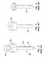
- FIG. 13is a side view of a trocar fixation device of the present invention.
- FIG. 14is a side view, partially in cross-section, of a trocar fixation device of the present invention depicting the trocar fixation device mounted onto a cannula;
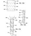
- FIGS. 15 a - 15 iincludes flat pattern layouts of trocar fixation devices of the present invention
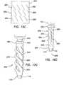
- FIGS. 16 a - 16 iincludes trocar fixation devices of the present invention mounted onto cannulas with the trocar fixation devices in a deactivated condition;
- FIGS. 17 a - 17 hincludes trocar fixation devices of the present invention mounted onto cannula with the trocar fixation device in an activated condition;
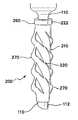
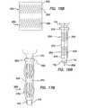
- FIG. 18is a perspective view of a trocar fixation device of the present invention mounted onto a cannula, the fixation device having helical slits extending distally in a counterclockwise direction and depicting a direction of rotating the fixation device in order to activate the fixation device;
- FIG. 19is a perspective view of a trocar fixation device of the present invention mounted onto a cannula, the fixation device having helical slits extending distally in a clockwise direction and depicting a direction of rotating the fixation device in order to activate the fixation device;
- FIG. 20is a side view, partially in cross-section, depicting the trocar fixation device of the present invention mounted onto a cannula and progressive steps of inserting the trocar into the body wall of a patient, activating the trocar fixation device and deactivating the trocar fixation device;
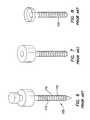
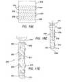
- FIG. 21is a side view of a trocar fixation device of the present invention, the trocar fixation device having varying thicknesses to facilitate progressive deployment of the fixation device;
- FIG. 22is a side view of the trocar fixation device of FIG. 21 depicting the progressive deployment of the trocar fixation device;
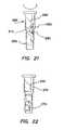
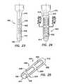
- FIG. 23is a side view of a trocar fixation device of the present invention mounted onto a cannula, the trocar fixation device having flaps that bias radially outwardly from an external surface of the cannula;
- FIG. 24is a side view of the trocar fixation device of FIG. 23 , further depicting an elongate tube mounted onto the cannula and exposing the flaps of the trocar fixation device;
- FIG. 25is a perspective view of the elongate tube of FIG. 24 ;
- FIG. 26is a section view taken from line 26 - 26 in FIG. 24 depicting the trocar fixation device in the activated condition;
- FIG. 27is a section view taken from line 27 - 27 in FIG. 24 depicting the trocar fixation device in the activated condition with the elongate tube being rotated to deactivate the trocar fixation device;
- FIG. 28is a section view taken from line 28 - 28 in FIG. 24 depicting the trocar fixation device in the deactivated condition.
- FIG. 29is a side view, partially in cross-section, depicting the trocar fixation device of FIG. 24 and progressive steps of inserting the trocar into the body wall of a patient, activating the trocar fixation device and deactivating the trocar fixation device
- a typical laparoscopic procedureis illustrated where a plurality of trocars 100 are placed through a body wall 50 , such as an abdominal wall, and into a body cavity 52 , such as an abdominal cavity.
- the body cavity 52is insufflated, or inflated with gas, to distend the body wall 50 and provide a working space for the laparoscopic procedure.
- the trocars 100each include a cannula 110 and a seal 150 . Positive pressure is maintained within the body cavity 52 by the seal 150 associated with the cannula 110 .
- the cannula 110must fit tightly through the incision through the body wall 50 and maintain a gas-tight seal against adjacent tissue. If positive pressure is lost, either through the seal 150 associated with the cannula 110 or the seal between the cannula and the adjacent tissue, the procedure may be compromised.
- the body wall 50may be greatly distended.
- the access sitesmay tend to enlarge under the distention of the body wall 50 and compromise the positioning and sealing of the cannula 110 .
- the manipulation of instruments 190 used through the trocars 100may result in movement of the cannulas 110 in either a proximal or distal direction and/or rotation of the cannulas 110 within the access site through the body wall 50 . As this occurs, some liquefaction may take place and the preferred relationship between the cannula 110 and the body tissue may be compromised.
- a typical assembled trocar 100is shown having a cannula 110 , a seal housing 150 and an obturator 160 .
- the cannula 110typically has a smooth exterior surface 112 so that it may be inserted through the body wall 50 easily.
- the seal housing 150contains a seal system that prevents retrograde gas-flow.
- the obturator 160is a cutting or piercing instrument that creates the pathway through the body wall 50 through which the cannula 110 follows. Surgical obturators 160 are generally sized and configured to create a defect in tissue that is appropriate for the associated cannula 110 .
- the defectmay have a tendency to enlarge during a surgical procedure as the trocar 100 or cannula 110 is manipulated.
- the cannula 110may move or even be inadvertently withdrawn due to the friction between the instrument 190 and the seal 150 of the trocar housing.
- a trocar 100 or access devicewhere the exterior surface 112 of the cannula 110 includes a plurality of raised features 115 .
- These raised features 115are sized and configured to increase resistance to proximal and distal motion as instruments 190 are maneuvered and especially as specimens are removed through the trocar 100 .
- the prior artincludes either sequential raised rings or a raised coarse-thread 115 . While the rings or threads 115 of the prior art may stabilize the cannula 110 to some degree, they do not necessarily seal the cannula 110 against the adjacent tissue of a body wall 50 . There can be substantial gas loss associated with the use of these systems.
- the raised rings or threads 115also increase the insertion force required to penetrate a body wall 50 and may damage delicate body-wall tissue or cause bleeding from the insertion site.
- the insertion forcemay be reduced in the instance of a continuous coarse thread 115 in comparison to a sequence of discrete raised rings or features as a threaded cannula 110 may actually be “screwed” into the tissue defect in accordance with the thread direction and pitch, rather than pushed through without appropriate rotation.
- a surgical access device, or trocar 100includes a cannula 110 having an inflatable balloon 120 associated with the distal-end portion 122 of the cannula.
- the balloon 120is sized and configured to fit snugly around the cannula 110 in the uninflated condition.
- the balloon 120is inflated after the cannula 110 is properly placed through the body wall 50 and into the body cavity 52 .
- the balloon 120is generally held against the interior surface 54 of the body wall 50 by a counter-force that is associated with a sliding counter-force member 180 .
- the sliding counter-force memberis associated with the proximal portion of the cannula 110 .
- the balloons 120 associated with the devices of the prior artare typically “thick-walled” structures constructed as part of the cannula 110 .
- the balloon 120is generally bonded to the distal-end portion 122 of the cannula 110 and an inflation channel or lumen is provided within the wall of the cannula.
- This constructioncan be complicated and expensive. Additionally, this construction requires that the cannula 110 and associated balloon 120 be inserted whether or not the balloon is required or used.
- one embodiment of the fixation device 200 of the present inventionincludes a flexible elongate tube 210 having a first, proximal end 212 , a second, distal end 214 , a lumen 216 extending between the proximal end and the distal end, a first, interior surface 218 and a second, exterior surface 220 .
- the elongate tube 210may also include a first, proximal-end region 222 , a second, distal-end region 224 , and a central region 226 that is positioned between the proximal-end region and the distal-end region.
- the fixation device 200may be used with existing trocars 100 and cannulas 110 with no need to alter the cannulas 110 , resulting in a fixation device 200 that may be packaged separately from the cannula 110 and placed on the cannula as needed.
- the cannula 110includes a first, interior surface 111 , a second, exterior surface 112 , a first, proximal end 113 , a second, distal end 114 , a lumen 130 extending between the proximal end and the distal end, a first, proximal-end region 116 , a second, distal-end region 117 , and a central region 118 that is positioned between the proximal-end region and the distal-end region.
- the elongate tube 210may be slipped over the second, exterior surface 112 of a cannula 110 .
- the second, distal end 114 of the cannula 110is inserted into the lumen 216 of the elongate tube 210 from the first, proximal end 212 of the elongate tube and advanced distally through the elongate tube at least until the second, distal end 114 of the cannula extends beyond the second, distal end 214 of the elongate tube.
- At least a portion of the second, distal-end region 224 of the elongate tube 210is coupled to the second, exterior surface 112 of the cannula 110 to form a gas-tight seal between the elongate tube and the cannula.
- the second, distal-end region 224 of the elongate tube 210is coupled to the second, distal-end region 117 of the cannula 110 . In another embodiment, the second, distal-end region 224 of the elongate tube 210 is coupled to the central region 118 of the cannula.
- the elongate tube 210may be coupled to the cannula 110 by bonding, mechanical means, a press seal, or by any other means that is well known in the art.
- the elongate tube 210includes a plurality of slits 250 positioned about a periphery within the central region 226 of the elongate tube, thereby forming a row 252 of slits within the central region.
- the slits 250 within a row 252may be substantially parallel to each other and may be either of substantially equal lengths (see FIGS. 15 a - 15 f and 15 h ) or of different lengths (see FIG.
- the slits 250are cut at an angle to the longitudinal axis 228 of the elongate tube 210 .
- the slits 250may be at any angle between about 20° and about 70° to the longitudinal axis 228 of the elongate tube 210 , however, those familiar in the art will recognize that other angles for the slits will produce successful results and are contemplated as within the scope of the present invention. Since the slits 250 are cut into a substantially cylindrical surface and are cut at an angle to the longitudinal axis 228 , the slits have a substantially helical form. Alternatively, the slits 250 may be of varying lengths (see FIG.
- the length of the slits 250may be between about 8.0 mm to about 35.0 mm, however, those familiar in the art will recognize that other lengths for the slits will produce successful results and are contemplated as within the scope of the present invention.
- the slits 250are depicted as being substantially linear, it is contemplated as part of the present invention that the slits may have other shapes.
- Adjacent rows 252 of slits 250may be either substantially rotatably aligned (see FIGS. 15 a and 15 b ) about the longitudinal axis 228 along the length of the elongate tube or rotatably offset (see FIGS. 15 c - 15 g ) about the longitudinal axis from each other.
- the fixation characteristics of the fixation device 200are activated by rotating the first, proximal-end region 222 of the elongate tube in a first direction in relation to the cannula and about the longitudinal axis 228 of the elongate tube (see FIGS. 17 a - 17 i ).
- the first, proximal-end region 222 of the elongate tubeis rotated in a first, clockwise direction to activate the fixation characteristics (see FIG. 19 ).
- the first, proximal-end region 222 of the elongate tube 210may include a handle portion 260 (see FIGS. 16 a - 16 i ) that enlarges the periphery of the first, proximal-end region to facilitate activation and deactivation of the fixation device 200 .
- the handle portion 260 of the elongate tube 210may either be an integral part of the elongate tube or be a separate piece coupled to the elongate tube.
- the body wall 50such as the abdominal wall, includes skin 300 , layers of muscle tissue 302 , and a layer of connective tissue 304 . Additionally, in the case of an abdominal wall, there is a final, internal membrane 306 referred to as the peritoneum 308 .
- the fixation device 200 of the present inventionis part of a trocar 100 . More particularly, the fixation device 200 is coupled to a cannula 110 as described above and a puncturing device, such as an obturator 160 , is inserted into the lumen 130 of the cannula.
- the trocar 100is pushed through the body wall 50 with a penetration force of sufficient magnitude to result in the penetration of the body wall.
- the trocar 100is advanced at least until a portion of the second, distal-end region 117 of the cannula is positioned within the body cavity 52 while the distal-most slits 250 on the elongate tube 210 are positioned within the body wall and not within the body cavity.
- the fixation device 200may be activated as described above.
- the activation of the fixation device 200causes the ridges 270 on the fixation device to deploy into the tissue of the body wall 50 , thereby substantially preventing any proximal or distal movement between the elongate tube 210 and the body wall.
- the fixation device 200Prior to removing the cannula 110 from the body wall 50 , the fixation device 200 is deactivated as described above, thereby causing the second, exterior surface 220 of the elongate tube 210 to return to a substantially smooth condition and reducing the potential to cause damage to the body wall during removal of the cannula.
- the elongate tube 210may be made of polyethylene, nylon, or other polymeric materials having similar properties that are well known in the art.
- the elongate tube 210may be fabricated through a molding process, extrusion process, or other process that is well known in the art for producing polymeric tubing.
- the elongate tubemay be made from a heat shrink polymer, such as polyolefin.
- another embodiment of the inventionincludes progressive deployment of the ridges 270 of the elongate tube 210 .
- Progressive deployment of the ridges 270is achieved by varying the thickness of the elongate tube 210 along its length such that at least one row 252 of slits 250 has a different thickness than an adjacent row of slits. More particularly, at least one row 252 of slits 250 is positioned within a region of the elongate tube 210 having a first thickness 280 and at least one other row 252 of slits 250 is positioned within a region of the elongate tube having a different, second thickness 282 .
- the varying thicknessmay be achieved by molding different regions of the elongate tube 210 with different thicknesses, by layering portions of the elongate tube, or by any other means well known in the art.
- progressive deployment of the ridges 270may be achieved by varying the stiffness of the elongate tube 210 along its length or by varying the slit 250 patterns from one row 252 to an adjacent row (see FIG. 16 i ).
- the fixation device 400includes a at least one flap 402 coupled to a cannula 110 on the second, exterior surface 112 within the central region 118 of the cannula 110 .
- the fixation device 400includes a plurality of flaps 402 . In a free, activated state, the at least one flap 402 biases radially outwardly from the cannula 110 and in a constrained, deactivated state, the at least one flap is maintained substantially parallel to the second, exterior surface 112 of the cannula.
- a plurality of flaps 402may be aligned substantially parallel to a longitudinal axis 124 of the cannula 110 .
- a plurality of flaps 402may be arranged in other patterns, such as a helical pattern, an annular pattern, a serpentine pattern, or any other pattern that is well known in the art.
- the at least one flap 402may include a parallelogram shape as depicted in FIG. 23 .
- the at least one flap 402may include other shapes, such as triangular, rectangular, square, other polygonal shapes, or curved.
- the fixation device 400includes an elongate tube 410 that is rotatably mounted onto the cannula 110 and over the at least one flap.
- the elongate tube 410includes a first, proximal end 412 , a second, distal end 414 , a lumen 416 extending between the proximal end and the distal end, a first, interior surface 418 , and a second, exterior surface 420 .
- the elongate tube 410may also include a first, proximal-end region 422 , a second, distal-end region 424 , and a central region 426 that is positioned between the proximal-end region and the distal-end region.
- the elongate tube 410further includes at least one opening 430 that extends between the first, interior surface 418 and the second, exterior surface 420 of the elongate tube 410 .
- the at least one opening 430is sized and positioned such that rotation of the elongate tube 410 in a first direction about the cannula 110 exposes at least one entire flap 402 through the at least one opening and allows the at least one flap to activate by protruding radially away from the second, exterior surface 112 of the cannula.
- the at least one opening 430may be positioned within the central region 426 of the elongate tube 410 .
- the elongate tube 410may be fabricated of polyethylene or any other material well known in the art that may be used for surgical purposes and that possesses sufficient stiffness to collapse the at least one flap 402 during deactivation of the fixation device 400 .
- the at least one flap 402may be fabricated through any of numerous available means.
- the at least one flap 402may be cut into a sleeve, such as a polymeric sleeve, the flap bent outwardly away from the sleeve, and the sleeve subsequently coupled to the central region 118 of the cannula 110 .
- the at least one flap 402may be overmolded onto the central region 118 of the cannula 110 .
- the at least one flap 402may be formed in a strip of material that is subsequently coupled to the central region 118 of the cannula 110 .
- the at least one flap 402may also be formed through any other means well known in the art and coupled to the central region 118 of the cannula 110 through any other means well known in the art.
- the at least one flap 402may be formed of polyethylene or any other material well known in the art that may be used for surgical purposes and that possesses properties of shape memory and flexibility.
- the fixation device 400 of the present inventionis part of a trocar 100 . More particularly, the fixation device 400 is coupled to a cannula 110 as described above and a puncturing device, such as an obturator 160 , is inserted into the lumen 130 of the cannula. With the fixation device 400 deactivated and the second, exterior surface 420 of the elongate tube 410 substantially smooth, the trocar 100 is pushed through the body wall 50 with a penetration force of sufficient magnitude to result in the penetration of the body wall.
- the trocar 100is advanced until at least a portion of the second, distal-end region 117 of the cannula is positioned within the body cavity 52 while the elongate tube 410 is positioned within the body wall and not within the body cavity.
- the fixation device 400With the fixation device 400 positioned in this manner, the fixation device may be activated as described above.
- the activation of the fixation device 400causes the at least one flap 402 on the activation device to deploy into the tissue of the body wall 50 , thereby substantially preventing any proximal or distal movement between the fixation device 400 and the body wall.
- the fixation device 400Prior to removing the cannula 110 from the body wall 50 , the fixation device 400 is deactivated as described above, thereby causing the fixation device 400 to return to a substantially smooth condition and reducing the potential to cause damage to the body wall during removal of the cannula.
Landscapes
- Health & Medical Sciences (AREA)
- Surgery (AREA)
- Life Sciences & Earth Sciences (AREA)
- Biomedical Technology (AREA)
- Nuclear Medicine, Radiotherapy & Molecular Imaging (AREA)
- Engineering & Computer Science (AREA)
- Pathology (AREA)
- Heart & Thoracic Surgery (AREA)
- Medical Informatics (AREA)
- Molecular Biology (AREA)
- Animal Behavior & Ethology (AREA)
- General Health & Medical Sciences (AREA)
- Public Health (AREA)
- Veterinary Medicine (AREA)
- Surgical Instruments (AREA)
Abstract
Description
Claims (62)
Priority Applications (7)
| Application Number | Priority Date | Filing Date | Title |
|---|---|---|---|
| US11/270,181US8157833B2 (en) | 2005-11-09 | 2005-11-09 | Trocars with advanced fixation |
| CA002632176ACA2632176A1 (en) | 2005-11-09 | 2006-10-25 | Trocars with advanced fixation |
| PCT/US2006/060212WO2007056627A1 (en) | 2005-11-09 | 2006-10-25 | Trocars with advanced fixation |
| AU2006311376AAU2006311376B2 (en) | 2005-11-09 | 2006-10-25 | Trocars with advanced fixation |
| EP06839534.2AEP1983910B1 (en) | 2005-11-09 | 2006-10-25 | Trocars with advanced fixation |
| JP2008540297AJP2009514651A (en) | 2005-11-09 | 2006-10-25 | Trocar with excellent fixing ability |
| US13/449,017US9700348B2 (en) | 2005-11-09 | 2012-04-17 | Trocars with advanced fixation |
Applications Claiming Priority (1)
| Application Number | Priority Date | Filing Date | Title |
|---|---|---|---|
| US11/270,181US8157833B2 (en) | 2005-11-09 | 2005-11-09 | Trocars with advanced fixation |
Related Child Applications (2)
| Application Number | Title | Priority Date | Filing Date |
|---|---|---|---|
| US13/449,017ContinuationUS9700348B2 (en) | 2005-11-09 | 2012-04-17 | Trocars with advanced fixation |
| US13/449,017DivisionUS9700348B2 (en) | 2005-11-09 | 2012-04-17 | Trocars with advanced fixation |
Publications (2)
| Publication Number | Publication Date |
|---|---|
| US20070106319A1 US20070106319A1 (en) | 2007-05-10 |
| US8157833B2true US8157833B2 (en) | 2012-04-17 |
Family
ID=37814668
Family Applications (2)
| Application Number | Title | Priority Date | Filing Date |
|---|---|---|---|
| US11/270,181Active2028-11-25US8157833B2 (en) | 2005-11-09 | 2005-11-09 | Trocars with advanced fixation |
| US13/449,017Active2025-11-24US9700348B2 (en) | 2005-11-09 | 2012-04-17 | Trocars with advanced fixation |
Family Applications After (1)
| Application Number | Title | Priority Date | Filing Date |
|---|---|---|---|
| US13/449,017Active2025-11-24US9700348B2 (en) | 2005-11-09 | 2012-04-17 | Trocars with advanced fixation |
Country Status (6)
| Country | Link |
|---|---|
| US (2) | US8157833B2 (en) |
| EP (1) | EP1983910B1 (en) |
| JP (1) | JP2009514651A (en) |
| AU (1) | AU2006311376B2 (en) |
| CA (1) | CA2632176A1 (en) |
| WO (1) | WO2007056627A1 (en) |
Cited By (22)
| Publication number | Priority date | Publication date | Assignee | Title |
|---|---|---|---|---|
| US20090105733A1 (en)* | 2007-10-22 | 2009-04-23 | Coleman James E | Anastomosis devices and methods |
| US20110196205A1 (en)* | 2010-02-05 | 2011-08-11 | Tyco Healthcare Group Lp | Surgical portal locking system |
| US20120265224A1 (en)* | 2008-11-06 | 2012-10-18 | Coleman James E | Gastric bypass devices and procedures |
| US20130303858A1 (en)* | 2008-02-13 | 2013-11-14 | Depuy Mitek, Llc | Compression expanded cannula |
| US8679150B1 (en) | 2013-03-15 | 2014-03-25 | Insera Therapeutics, Inc. | Shape-set textile structure based mechanical thrombectomy methods |
| US8690907B1 (en) | 2013-03-15 | 2014-04-08 | Insera Therapeutics, Inc. | Vascular treatment methods |
| US8715316B1 (en) | 2013-07-29 | 2014-05-06 | Insera Therapeutics, Inc. | Offset vascular treatment devices |
| US8936608B2 (en) | 2006-02-03 | 2015-01-20 | James E. Coleman | Wound closure devices and systems |
| US9034007B2 (en) | 2007-09-21 | 2015-05-19 | Insera Therapeutics, Inc. | Distal embolic protection devices with a variable thickness microguidewire and methods for their use |
| US9247930B2 (en) | 2011-12-21 | 2016-02-02 | James E. Coleman | Devices and methods for occluding or promoting fluid flow |
| US20160045220A1 (en)* | 2014-08-15 | 2016-02-18 | Applied Medical Resources Corporation | Natural orifice surgery system |
| US9314324B2 (en) | 2013-03-15 | 2016-04-19 | Insera Therapeutics, Inc. | Vascular treatment devices and methods |
| US20160354113A1 (en)* | 2015-06-04 | 2016-12-08 | DePuy Synthes Products, Inc. | Surgical Cannula System and Method of Use |
| US20170100160A1 (en)* | 2015-10-08 | 2017-04-13 | Karl Storz Gmbh & Co. Kg | Access system for endoscopic operations |
| US20180214177A1 (en)* | 2015-01-28 | 2018-08-02 | Unimicro Medical Systems (Shenzhen) Co., Ltd. | Fully separable piercer |
| US10215215B2 (en)* | 2015-04-09 | 2019-02-26 | Ningbo Geely Automobile Research & Development Co., Ltd. | Tolerance absorber sleeve and assembly |
| US10327809B2 (en) | 2016-02-29 | 2019-06-25 | Covidien Lp | Clip collar advanced fixation |
| US10390926B2 (en) | 2013-07-29 | 2019-08-27 | Insera Therapeutics, Inc. | Aspiration devices and methods |
| US10525179B2 (en) | 2016-03-31 | 2020-01-07 | Heartware, Inc. | Crenellated inflow cannula |
| US20200281579A1 (en)* | 2019-03-08 | 2020-09-10 | Medos International Sarl | Surface features for device retention |
| US20210128142A1 (en)* | 2019-07-08 | 2021-05-06 | Cannuflow, Inc. | Arthroscopic cannula and suture management system |
| US11172957B2 (en) | 2018-02-07 | 2021-11-16 | Stryker Corporation | Surgical cannula and methods of use |
Families Citing this family (48)
| Publication number | Priority date | Publication date | Assignee | Title |
|---|---|---|---|---|
| US8992085B2 (en)* | 1999-06-24 | 2015-03-31 | Alan D. Olin | Self-supporting storage bag with resealable pour spout |
| WO2007093957A2 (en)* | 2006-02-17 | 2007-08-23 | Roesch Theodor Gerhard | A cannula with a deployable external thread |
| US8348973B2 (en)* | 2006-09-06 | 2013-01-08 | Covidien Lp | Bioactive substance in a barbed suture |
| US8152775B2 (en)* | 2007-10-17 | 2012-04-10 | Tyco Healthcare Group Lp | Access port using shape altering anchor |
| US20090105691A1 (en)* | 2007-10-17 | 2009-04-23 | Tyco Healthcare Group Lp | Access port using shape memory anchor |
| US20090105659A1 (en)* | 2007-10-17 | 2009-04-23 | Tyco Healthcare Group Lp | Anchoring cannula |
| US20090118747A1 (en)* | 2007-11-05 | 2009-05-07 | Tyco Healthcare Group Lp | Novel surgical fastener |
| US8888810B2 (en) | 2008-02-20 | 2014-11-18 | Covidien Lp | Compound barb medical device and method |
| US8454653B2 (en) | 2008-02-20 | 2013-06-04 | Covidien Lp | Compound barb medical device and method |
| US7850667B2 (en)* | 2008-06-27 | 2010-12-14 | Tyco Healthcare Group Lp | Low profile instrument access device |
| US20100204729A1 (en)* | 2008-09-11 | 2010-08-12 | Ahmad Robert Hadba | Tapered Looped Suture |
| JP5161714B2 (en) | 2008-09-19 | 2013-03-13 | オリンパスメディカルシステムズ株式会社 | Medical equipment |
| US8323316B2 (en) | 2008-10-09 | 2012-12-04 | Covidien Lp | Knotted suture end effector |
| WO2010109696A1 (en)* | 2009-03-25 | 2010-09-30 | オリンパスメディカルシステムズ株式会社 | Medical device |
| US8206291B2 (en) | 2009-03-27 | 2012-06-26 | Tyco Healthcare Group Lp | Portal device |
| EP3178519A1 (en) | 2009-09-22 | 2017-06-14 | Doheny Eye Institute | Adjustable cannula systems and devices |
| US8491533B2 (en)* | 2009-10-08 | 2013-07-23 | Ethicon Endo-Surgery, Inc. | Trocar assembly |
| US8932249B2 (en) | 2009-10-08 | 2015-01-13 | Ethicon Endo-Surgery, Inc. | Trocar assembly |
| US20110087159A1 (en)* | 2009-10-08 | 2011-04-14 | Parihar Shailendra K | Trocar Assembly |
| US20110118552A1 (en)* | 2009-11-18 | 2011-05-19 | Tyco Healthcare Group Lp | Port fixation device |
| WO2011072100A2 (en)* | 2009-12-11 | 2011-06-16 | Ethicon Endo-Surgery, Inc. | Methods and devices for providing access into a body cavity |
| US8357088B2 (en)* | 2009-12-11 | 2013-01-22 | Ethicon Endo-Surgery, Inc. | Methods and devices for providing access into a body cavity |
| US8414483B2 (en)* | 2009-12-11 | 2013-04-09 | Ethicon Endo-Surgery, Inc. | Methods and devices for providing access into a body cavity |
| US8343106B2 (en) | 2009-12-23 | 2013-01-01 | Alcon Research, Ltd. | Ophthalmic valved trocar vent |
| JP5990103B2 (en) | 2009-12-23 | 2016-09-07 | アルコン リサーチ, リミテッド | Ophthalmic valved trocar cannula |
| US10080838B2 (en)* | 2010-07-12 | 2018-09-25 | Ramot At Tel-Aviv University Ltd. | Catheter cannula with anchoring elements, catheter including thereof, and/or catheterization method using thereof |
| US20120245510A1 (en)* | 2011-03-22 | 2012-09-27 | Rakower Stephen R | Adhesiolysis system |
| US8758236B2 (en)* | 2011-05-10 | 2014-06-24 | Applied Medical Resources Corporation | Wound retractor |
| DE102011055129A1 (en)* | 2011-11-08 | 2013-05-08 | Aesculap Ag | Surgical Access Device and Surgical Access System |
| US9198657B2 (en)* | 2012-09-13 | 2015-12-01 | Basil Anthony Kocur | Anchor unit implant |
| US9149294B2 (en) | 2013-01-24 | 2015-10-06 | Hybrid Cannula LP | Hybrid cannula and methods for manufacturing the same |
| US9119663B2 (en) | 2013-01-24 | 2015-09-01 | Hybrid Cannula LP | Hybrid cannula and methods for manufacturing the same |
| DE102013004964B4 (en)* | 2013-03-22 | 2016-11-03 | Joimax Gmbh | Instrument set and method for inserting a basket into the disc space between two vertebral bodies |
| WO2014210586A1 (en)* | 2013-06-29 | 2014-12-31 | Robert Edward Morris | Safety cannula |
| DE112014004014B4 (en) | 2013-09-03 | 2023-12-14 | Fujifilm Corporation | Endoscopic surgical device and overtube |
| JP6084697B2 (en) | 2013-09-03 | 2017-02-22 | 富士フイルム株式会社 | Endoscopic surgical apparatus, outer tube, and outer tube |
| DE112014004020B4 (en) | 2013-09-03 | 2023-12-14 | Fujifilm Corporation | Endoscopic surgical device and overtube |
| WO2015033909A1 (en) | 2013-09-03 | 2015-03-12 | 富士フイルム株式会社 | Endoscopic surgical device and outer sleeve |
| EP3046486A1 (en)* | 2013-09-20 | 2016-07-27 | Applied Medical Resources Corporation | Natural orifice access device |
| US9999542B2 (en) | 2014-07-16 | 2018-06-19 | Doheny Eye Institute | Systems, methods, and devices for cannula insertion |
| US20160345954A1 (en)* | 2015-05-27 | 2016-12-01 | James F. Marino | Anchor Devices and Methods of Use |
| USD842984S1 (en)* | 2015-12-09 | 2019-03-12 | Dentsply Ih Ab | Catheter |
| USD833606S1 (en)* | 2016-02-29 | 2018-11-13 | Csp Technologies, Inc. | Cannula sensor carrier |
| WO2018183185A1 (en)* | 2017-03-28 | 2018-10-04 | C.R. Bard, Inc. | Implantable prosthetic device |
| CA2993590A1 (en) | 2017-09-06 | 2019-03-06 | Xpan Inc. | Radially expandable cannula system |
| KR102221591B1 (en)* | 2019-02-21 | 2021-03-02 | (주)이롭 | Trocar for Laparoscopic Surgery |
| US11931070B1 (en) | 2020-01-30 | 2024-03-19 | Hybrid Cannula LP | Half pipe cannula and methods of manufacturing and using half pipe cannula |
| CA3171410A1 (en) | 2020-03-13 | 2021-09-16 | Xpan Inc. | Radially expandable cannula devices, and systems and methods for using them |
Citations (35)
| Publication number | Priority date | Publication date | Assignee | Title |
|---|---|---|---|---|
| US3817251A (en) | 1972-10-04 | 1974-06-18 | H Hasson | Laparoscope cannula |
| US3970090A (en) | 1975-02-03 | 1976-07-20 | Physio Medics, Inc. | Catheter |
| US4762130A (en) | 1987-01-15 | 1988-08-09 | Thomas J. Fogarty | Catheter with corkscrew-like balloon |
| US5122122A (en) | 1989-11-22 | 1992-06-16 | Dexide, Incorporated | Locking trocar sleeve |
| US5147316A (en) | 1990-11-19 | 1992-09-15 | Castillenti Thomas A | Laparoscopic trocar with self-locking port sleeve |
| US5176697A (en) | 1989-04-06 | 1993-01-05 | Hasson Harrith M | Laparoscopic cannula |
| US5217441A (en) | 1989-08-15 | 1993-06-08 | United States Surgical Corporation | Trocar guide tube positioning device |
| US5257975A (en)* | 1992-08-14 | 1993-11-02 | Edward Weck Incorporated | Cannula retention device |
| US5271380A (en) | 1990-11-06 | 1993-12-21 | Siegfried Riek | Penetration instrument |
| US5330497A (en) | 1989-11-22 | 1994-07-19 | Dexide, Inc. | Locking trocar sleeve |
| US5330501A (en) | 1991-05-30 | 1994-07-19 | United States Surgical Corporation | Tissue gripping device for use with a cannula and a cannula incorporating the device |
| US5352211A (en) | 1993-07-11 | 1994-10-04 | Louisville Laboratories | External stability device |
| US5403336A (en) | 1993-09-20 | 1995-04-04 | General Surgical Innovations, Inc. | Skin seal device and assembly thereof |
| US5407433A (en) | 1993-02-10 | 1995-04-18 | Origin Medsystems, Inc. | Gas-tight seal accommodating surgical instruments with a wide range of diameters |
| US5411483A (en) | 1993-02-10 | 1995-05-02 | Origin Medsystems, Inc. | Gas-tight seal accommodating surgical instruments with a wide range of diameters |
| US5445615A (en) | 1991-11-06 | 1995-08-29 | Yoon; Inbae | Surgical instrument stabilizer |
| US5501695A (en)* | 1992-05-27 | 1996-03-26 | The Anspach Effort, Inc. | Fastener for attaching objects to bones |
| US5653690A (en) | 1992-12-30 | 1997-08-05 | Medtronic, Inc. | Catheter having a balloon with retention enhancement |
| US5697913A (en) | 1996-08-09 | 1997-12-16 | Ethicon Endo-Surgery, Inc. | Trocar including cannula with stepped region |
| US5814058A (en) | 1993-03-05 | 1998-09-29 | Innerdyne, Inc. | Method and apparatus employing conformable sleeve for providing percutaneous access |
| US5836913A (en) | 1997-05-02 | 1998-11-17 | Innerdyne, Inc. | Device and method for accessing a body cavity |
| US5893850A (en)* | 1996-11-12 | 1999-04-13 | Cachia; Victor V. | Bone fixation device |
| US6099506A (en)* | 1997-09-26 | 2000-08-08 | Macoviak; John A. | Introducer and perfusion cannula |
| DE20012003U1 (en) | 2000-07-11 | 2000-10-12 | Braun, Michael, 71522 Backnang | Device for introducing particles into a body tissue, in particular muscle tissue |
| WO2001089398A1 (en) | 2000-05-23 | 2001-11-29 | Mount Olympus Devices Llc | Reliable surgical access cannula system and related methods |
| FR2810555A1 (en) | 2000-06-26 | 2001-12-28 | Soprane Sa | Re-usable catheter for transvaginal treatment and diagnosis of infertility comprises inner chamber for guide and flexible vane retaining member |
| US20020026137A1 (en)* | 1998-08-12 | 2002-02-28 | Yencho Stephen A. | Method and system for attaching a graft to a blood vessel |
| US6432085B1 (en) | 1999-03-17 | 2002-08-13 | Tyco Healthcare Group Lp | Self-retaining surgical access instrument |
| WO2003011143A2 (en) | 2001-07-27 | 2003-02-13 | Senorx, Inc. | Dilation devices and methods for removing tissue specimens |
| US6524283B1 (en) | 1994-10-07 | 2003-02-25 | Sherwood Services Ag | Method and apparatus for anchoring laparoscopic instruments |
| US20040068228A1 (en) | 2002-10-04 | 2004-04-08 | Jon Cunningham | Device and method for stabilizing catheters |
| US6719509B1 (en)* | 2002-10-04 | 2004-04-13 | Joker Ind Co Ltd | Expansion screw |
| US6808492B2 (en) | 2002-08-16 | 2004-10-26 | Linvatec Corporation | Endoscopic cannula fixation system |
| US20050143827A1 (en)* | 1999-01-27 | 2005-06-30 | Disco-O-Tech Medical Technologies Ltd. | Expandable intervertebral spacer |
| US7691089B2 (en) | 2005-06-21 | 2010-04-06 | Tyco Healthcare Group Lp | Adjustable trocar washer |
Family Cites Families (11)
| Publication number | Priority date | Publication date | Assignee | Title |
|---|---|---|---|---|
| US3108595A (en)* | 1960-08-08 | 1963-10-29 | Alfred P Overment | Retention catheter |
| US4331423A (en)* | 1981-03-09 | 1982-05-25 | Yanney Jr James F M | Method and apparatus for connecting an artificial tooth portion to a dentin portion |
| US5634911A (en)* | 1995-05-19 | 1997-06-03 | General Surgical Innovations, Inc. | Screw-type skin seal with inflatable membrane |
| US5571162A (en)* | 1995-06-07 | 1996-11-05 | Intermedics, Inc. | Transvenous defibrillation lead with side hooks |
| US6575973B1 (en)* | 2000-10-26 | 2003-06-10 | Safedrip Ltd. | Self locking intramedullary nail |
| US7160309B2 (en)* | 2002-12-31 | 2007-01-09 | Laveille Kao Voss | Systems for anchoring a medical device in a body lumen |
| DE102004009429A1 (en)* | 2004-02-24 | 2005-09-22 | Biedermann Motech Gmbh | Bone anchoring element |
| US20050256458A1 (en)* | 2004-04-19 | 2005-11-17 | Eben Howard And Pamela A. Howard | Self-anchoring catheter and method for using same |
| US8062305B2 (en)* | 2005-03-16 | 2011-11-22 | Tyco Healthcare Group Lp | Surgical portal with enhanced retention capabilities |
| US20060264951A1 (en)* | 2005-05-18 | 2006-11-23 | Nelson Charles L | Minimally Invasive Actuable Bone Fixation Devices Having a Retractable Interdigitation Process |
| KR101145415B1 (en)* | 2005-07-08 | 2012-05-15 | 비이더만 모테크 게엠베하 & 코. 카게 | Bone Anchoring Element |
- 2005
- 2005-11-09USUS11/270,181patent/US8157833B2/enactiveActive
- 2006
- 2006-10-25CACA002632176Apatent/CA2632176A1/ennot_activeAbandoned
- 2006-10-25JPJP2008540297Apatent/JP2009514651A/enactivePending
- 2006-10-25AUAU2006311376Apatent/AU2006311376B2/ennot_activeCeased
- 2006-10-25WOPCT/US2006/060212patent/WO2007056627A1/enactiveApplication Filing
- 2006-10-25EPEP06839534.2Apatent/EP1983910B1/enactiveActive
- 2012
- 2012-04-17USUS13/449,017patent/US9700348B2/enactiveActive
Patent Citations (36)
| Publication number | Priority date | Publication date | Assignee | Title |
|---|---|---|---|---|
| US3817251A (en) | 1972-10-04 | 1974-06-18 | H Hasson | Laparoscope cannula |
| US3970090A (en) | 1975-02-03 | 1976-07-20 | Physio Medics, Inc. | Catheter |
| US4762130A (en) | 1987-01-15 | 1988-08-09 | Thomas J. Fogarty | Catheter with corkscrew-like balloon |
| US5176697A (en) | 1989-04-06 | 1993-01-05 | Hasson Harrith M | Laparoscopic cannula |
| US5217441A (en) | 1989-08-15 | 1993-06-08 | United States Surgical Corporation | Trocar guide tube positioning device |
| US5122122A (en) | 1989-11-22 | 1992-06-16 | Dexide, Incorporated | Locking trocar sleeve |
| US5330497A (en) | 1989-11-22 | 1994-07-19 | Dexide, Inc. | Locking trocar sleeve |
| US5271380A (en) | 1990-11-06 | 1993-12-21 | Siegfried Riek | Penetration instrument |
| US5147316A (en) | 1990-11-19 | 1992-09-15 | Castillenti Thomas A | Laparoscopic trocar with self-locking port sleeve |
| US5330501A (en) | 1991-05-30 | 1994-07-19 | United States Surgical Corporation | Tissue gripping device for use with a cannula and a cannula incorporating the device |
| US5445615A (en) | 1991-11-06 | 1995-08-29 | Yoon; Inbae | Surgical instrument stabilizer |
| US5472429A (en) | 1991-11-06 | 1995-12-05 | Yoon; Inbae | Surgical instrument stabilizer |
| US5501695A (en)* | 1992-05-27 | 1996-03-26 | The Anspach Effort, Inc. | Fastener for attaching objects to bones |
| US5257975A (en)* | 1992-08-14 | 1993-11-02 | Edward Weck Incorporated | Cannula retention device |
| US5653690A (en) | 1992-12-30 | 1997-08-05 | Medtronic, Inc. | Catheter having a balloon with retention enhancement |
| US5407433A (en) | 1993-02-10 | 1995-04-18 | Origin Medsystems, Inc. | Gas-tight seal accommodating surgical instruments with a wide range of diameters |
| US5411483A (en) | 1993-02-10 | 1995-05-02 | Origin Medsystems, Inc. | Gas-tight seal accommodating surgical instruments with a wide range of diameters |
| US5814058A (en) | 1993-03-05 | 1998-09-29 | Innerdyne, Inc. | Method and apparatus employing conformable sleeve for providing percutaneous access |
| US5352211A (en) | 1993-07-11 | 1994-10-04 | Louisville Laboratories | External stability device |
| US5403336A (en) | 1993-09-20 | 1995-04-04 | General Surgical Innovations, Inc. | Skin seal device and assembly thereof |
| US6524283B1 (en) | 1994-10-07 | 2003-02-25 | Sherwood Services Ag | Method and apparatus for anchoring laparoscopic instruments |
| US5697913A (en) | 1996-08-09 | 1997-12-16 | Ethicon Endo-Surgery, Inc. | Trocar including cannula with stepped region |
| US5893850A (en)* | 1996-11-12 | 1999-04-13 | Cachia; Victor V. | Bone fixation device |
| US5836913A (en) | 1997-05-02 | 1998-11-17 | Innerdyne, Inc. | Device and method for accessing a body cavity |
| US6099506A (en)* | 1997-09-26 | 2000-08-08 | Macoviak; John A. | Introducer and perfusion cannula |
| US20020026137A1 (en)* | 1998-08-12 | 2002-02-28 | Yencho Stephen A. | Method and system for attaching a graft to a blood vessel |
| US20050143827A1 (en)* | 1999-01-27 | 2005-06-30 | Disco-O-Tech Medical Technologies Ltd. | Expandable intervertebral spacer |
| US6432085B1 (en) | 1999-03-17 | 2002-08-13 | Tyco Healthcare Group Lp | Self-retaining surgical access instrument |
| WO2001089398A1 (en) | 2000-05-23 | 2001-11-29 | Mount Olympus Devices Llc | Reliable surgical access cannula system and related methods |
| FR2810555A1 (en) | 2000-06-26 | 2001-12-28 | Soprane Sa | Re-usable catheter for transvaginal treatment and diagnosis of infertility comprises inner chamber for guide and flexible vane retaining member |
| DE20012003U1 (en) | 2000-07-11 | 2000-10-12 | Braun, Michael, 71522 Backnang | Device for introducing particles into a body tissue, in particular muscle tissue |
| WO2003011143A2 (en) | 2001-07-27 | 2003-02-13 | Senorx, Inc. | Dilation devices and methods for removing tissue specimens |
| US6808492B2 (en) | 2002-08-16 | 2004-10-26 | Linvatec Corporation | Endoscopic cannula fixation system |
| US20040068228A1 (en) | 2002-10-04 | 2004-04-08 | Jon Cunningham | Device and method for stabilizing catheters |
| US6719509B1 (en)* | 2002-10-04 | 2004-04-13 | Joker Ind Co Ltd | Expansion screw |
| US7691089B2 (en) | 2005-06-21 | 2010-04-06 | Tyco Healthcare Group Lp | Adjustable trocar washer |
Non-Patent Citations (2)
| Title |
|---|
| European Patent Office, The International Search Report and the Written Opinion of the International Searching Authority for PCT Application No. PCT/US2006/060212 mailed Mar. 21, 2007. |
| The International Bureau of WIPO, The International Preliminary Report on Patentability for PCT Application No. PCT/US2006/060212 dated May 14, 2008. |
Cited By (93)
| Publication number | Priority date | Publication date | Assignee | Title |
|---|---|---|---|---|
| US8936608B2 (en) | 2006-02-03 | 2015-01-20 | James E. Coleman | Wound closure devices and systems |
| US9034007B2 (en) | 2007-09-21 | 2015-05-19 | Insera Therapeutics, Inc. | Distal embolic protection devices with a variable thickness microguidewire and methods for their use |
| US20090105733A1 (en)* | 2007-10-22 | 2009-04-23 | Coleman James E | Anastomosis devices and methods |
| US9301761B2 (en) | 2007-10-22 | 2016-04-05 | James E. Coleman | Anastomosis devices and methods |
| US10034669B2 (en) | 2007-10-22 | 2018-07-31 | James E. Coleman | Anastomosis devices and methods |
| US20130303858A1 (en)* | 2008-02-13 | 2013-11-14 | Depuy Mitek, Llc | Compression expanded cannula |
| US9161747B2 (en)* | 2008-02-13 | 2015-10-20 | Depuy Mitek, Llc | Compression expanded cannula |
| US8672958B2 (en)* | 2008-11-06 | 2014-03-18 | James E. Coleman | Gastric bypass devices and procedures |
| US20120265224A1 (en)* | 2008-11-06 | 2012-10-18 | Coleman James E | Gastric bypass devices and procedures |
| US9289580B2 (en) | 2008-11-06 | 2016-03-22 | James E. Coleman | Gastric bypass devices and procedures |
| US20110196205A1 (en)* | 2010-02-05 | 2011-08-11 | Tyco Healthcare Group Lp | Surgical portal locking system |
| US10426448B2 (en) | 2011-12-21 | 2019-10-01 | James E. Coleman | Devices and methods for occluding or promoting fluid flow |
| US11672517B2 (en) | 2011-12-21 | 2023-06-13 | James E. Coleman | Methods for occluding or promoting fluid flow |
| US9247930B2 (en) | 2011-12-21 | 2016-02-02 | James E. Coleman | Devices and methods for occluding or promoting fluid flow |
| US10335260B2 (en) | 2013-03-15 | 2019-07-02 | Insera Therapeutics, Inc. | Methods of treating a thrombus in a vein using cyclical aspiration patterns |
| US8721676B1 (en) | 2013-03-15 | 2014-05-13 | Insera Therapeutics, Inc. | Slotted vascular treatment devices |
| US8733618B1 (en) | 2013-03-15 | 2014-05-27 | Insera Therapeutics, Inc. | Methods of coupling parts of vascular treatment systems |
| US8747432B1 (en) | 2013-03-15 | 2014-06-10 | Insera Therapeutics, Inc. | Woven vascular treatment devices |
| US8753371B1 (en) | 2013-03-15 | 2014-06-17 | Insera Therapeutics, Inc. | Woven vascular treatment systems |
| US8783151B1 (en) | 2013-03-15 | 2014-07-22 | Insera Therapeutics, Inc. | Methods of manufacturing vascular treatment devices |
| US8679150B1 (en) | 2013-03-15 | 2014-03-25 | Insera Therapeutics, Inc. | Shape-set textile structure based mechanical thrombectomy methods |
| US11298144B2 (en) | 2013-03-15 | 2022-04-12 | Insera Therapeutics, Inc. | Thrombus aspiration facilitation systems |
| US8789452B1 (en) | 2013-03-15 | 2014-07-29 | Insera Therapeutics, Inc. | Methods of manufacturing woven vascular treatment devices |
| US10463468B2 (en) | 2013-03-15 | 2019-11-05 | Insera Therapeutics, Inc. | Thrombus aspiration with different intensity levels |
| US8690907B1 (en) | 2013-03-15 | 2014-04-08 | Insera Therapeutics, Inc. | Vascular treatment methods |
| US10342655B2 (en) | 2013-03-15 | 2019-07-09 | Insera Therapeutics, Inc. | Methods of treating a thrombus in an artery using cyclical aspiration patterns |
| US8715315B1 (en) | 2013-03-15 | 2014-05-06 | Insera Therapeutics, Inc. | Vascular treatment systems |
| US10251739B2 (en) | 2013-03-15 | 2019-04-09 | Insera Therapeutics, Inc. | Thrombus aspiration using an operator-selectable suction pattern |
| US9901435B2 (en) | 2013-03-15 | 2018-02-27 | Insera Therapeutics, Inc. | Longitudinally variable vascular treatment devices |
| US9833251B2 (en) | 2013-03-15 | 2017-12-05 | Insera Therapeutics, Inc. | Variably bulbous vascular treatment devices |
| US8852227B1 (en) | 2013-03-15 | 2014-10-07 | Insera Therapeutics, Inc. | Woven radiopaque patterns |
| US9750524B2 (en) | 2013-03-15 | 2017-09-05 | Insera Therapeutics, Inc. | Shape-set textile structure based mechanical thrombectomy systems |
| US9592068B2 (en) | 2013-03-15 | 2017-03-14 | Insera Therapeutics, Inc. | Free end vascular treatment systems |
| US9314324B2 (en) | 2013-03-15 | 2016-04-19 | Insera Therapeutics, Inc. | Vascular treatment devices and methods |
| US8715314B1 (en) | 2013-03-15 | 2014-05-06 | Insera Therapeutics, Inc. | Vascular treatment measurement methods |
| US8721677B1 (en) | 2013-03-15 | 2014-05-13 | Insera Therapeutics, Inc. | Variably-shaped vascular devices |
| US9179995B2 (en) | 2013-03-15 | 2015-11-10 | Insera Therapeutics, Inc. | Methods of manufacturing slotted vascular treatment devices |
| US9179931B2 (en) | 2013-03-15 | 2015-11-10 | Insera Therapeutics, Inc. | Shape-set textile structure based mechanical thrombectomy systems |
| US8882797B2 (en) | 2013-03-15 | 2014-11-11 | Insera Therapeutics, Inc. | Methods of embolic filtering |
| US8895891B2 (en) | 2013-03-15 | 2014-11-25 | Insera Therapeutics, Inc. | Methods of cutting tubular devices |
| US8904914B2 (en) | 2013-03-15 | 2014-12-09 | Insera Therapeutics, Inc. | Methods of using non-cylindrical mandrels |
| US8910555B2 (en) | 2013-03-15 | 2014-12-16 | Insera Therapeutics, Inc. | Non-cylindrical mandrels |
| US8715317B1 (en) | 2013-07-29 | 2014-05-06 | Insera Therapeutics, Inc. | Flow diverting devices |
| US8828045B1 (en) | 2013-07-29 | 2014-09-09 | Insera Therapeutics, Inc. | Balloon catheters |
| US8728116B1 (en) | 2013-07-29 | 2014-05-20 | Insera Therapeutics, Inc. | Slotted catheters |
| US8728117B1 (en) | 2013-07-29 | 2014-05-20 | Insera Therapeutics, Inc. | Flow disrupting devices |
| US8932321B1 (en) | 2013-07-29 | 2015-01-13 | Insera Therapeutics, Inc. | Aspiration systems |
| US8870901B1 (en) | 2013-07-29 | 2014-10-28 | Insera Therapeutics, Inc. | Two-way shape memory vascular treatment systems |
| US8869670B1 (en) | 2013-07-29 | 2014-10-28 | Insera Therapeutics, Inc. | Methods of manufacturing variable porosity devices |
| US8870910B1 (en) | 2013-07-29 | 2014-10-28 | Insera Therapeutics, Inc. | Methods of decoupling joints |
| US8784446B1 (en) | 2013-07-29 | 2014-07-22 | Insera Therapeutics, Inc. | Circumferentially offset variable porosity devices |
| US8872068B1 (en) | 2013-07-29 | 2014-10-28 | Insera Therapeutics, Inc. | Devices for modifying hypotubes |
| US8735777B1 (en) | 2013-07-29 | 2014-05-27 | Insera Therapeutics, Inc. | Heat treatment systems |
| US8866049B1 (en) | 2013-07-29 | 2014-10-21 | Insera Therapeutics, Inc. | Methods of selectively heat treating tubular devices |
| US8790365B1 (en) | 2013-07-29 | 2014-07-29 | Insera Therapeutics, Inc. | Fistula flow disruptor methods |
| US8863631B1 (en) | 2013-07-29 | 2014-10-21 | Insera Therapeutics, Inc. | Methods of manufacturing flow diverting devices |
| US8932320B1 (en) | 2013-07-29 | 2015-01-13 | Insera Therapeutics, Inc. | Methods of aspirating thrombi |
| US8859934B1 (en) | 2013-07-29 | 2014-10-14 | Insera Therapeutics, Inc. | Methods for slag removal |
| US10751159B2 (en) | 2013-07-29 | 2020-08-25 | Insera Therapeutics, Inc. | Systems for aspirating thrombus during neurosurgical procedures |
| US8845678B1 (en) | 2013-07-29 | 2014-09-30 | Insera Therapeutics Inc. | Two-way shape memory vascular treatment methods |
| US8795330B1 (en) | 2013-07-29 | 2014-08-05 | Insera Therapeutics, Inc. | Fistula flow disruptors |
| US8845679B1 (en) | 2013-07-29 | 2014-09-30 | Insera Therapeutics, Inc. | Variable porosity flow diverting devices |
| US8803030B1 (en) | 2013-07-29 | 2014-08-12 | Insera Therapeutics, Inc. | Devices for slag removal |
| US8715316B1 (en) | 2013-07-29 | 2014-05-06 | Insera Therapeutics, Inc. | Offset vascular treatment devices |
| US10390926B2 (en) | 2013-07-29 | 2019-08-27 | Insera Therapeutics, Inc. | Aspiration devices and methods |
| US8816247B1 (en) | 2013-07-29 | 2014-08-26 | Insera Therapeutics, Inc. | Methods for modifying hypotubes |
| US8813625B1 (en) | 2013-07-29 | 2014-08-26 | Insera Therapeutics, Inc. | Methods of manufacturing variable porosity flow diverting devices |
| US10952768B2 (en)* | 2014-08-15 | 2021-03-23 | Applied Medical Resources Corporation | Natural orifice surgery system |
| US12262914B2 (en)* | 2014-08-15 | 2025-04-01 | Applied Medical Resources Corporation | Natural orifice surgery system |
| US10172641B2 (en)* | 2014-08-15 | 2019-01-08 | Applied Medical Resources Corporation | Natural orifice surgery system |
| US20160045220A1 (en)* | 2014-08-15 | 2016-02-18 | Applied Medical Resources Corporation | Natural orifice surgery system |
| US11583316B2 (en)* | 2014-08-15 | 2023-02-21 | Applied Medical Resources Corporation | Natural orifice surgery system |
| US20210177458A1 (en)* | 2014-08-15 | 2021-06-17 | Applied Medical Resources Corporation | Natural orifice surgery system |
| US20180214177A1 (en)* | 2015-01-28 | 2018-08-02 | Unimicro Medical Systems (Shenzhen) Co., Ltd. | Fully separable piercer |
| US10575871B2 (en)* | 2015-01-28 | 2020-03-03 | Unimicro Medical Systems (Shenzhen) Co., Ltd. | Fully detachable trocar |
| US10215215B2 (en)* | 2015-04-09 | 2019-02-26 | Ningbo Geely Automobile Research & Development Co., Ltd. | Tolerance absorber sleeve and assembly |
| US10357282B2 (en)* | 2015-06-04 | 2019-07-23 | Medos International Sarl | Orburator for expandable catheter |
| US20180042642A1 (en)* | 2015-06-04 | 2018-02-15 | Medos International Sarl | Obturator for Expandable Catheter |
| US20160354113A1 (en)* | 2015-06-04 | 2016-12-08 | DePuy Synthes Products, Inc. | Surgical Cannula System and Method of Use |
| US9808282B2 (en)* | 2015-06-04 | 2017-11-07 | Medos International Sarl | Surgical cannula system and method of use |
| US20170100160A1 (en)* | 2015-10-08 | 2017-04-13 | Karl Storz Gmbh & Co. Kg | Access system for endoscopic operations |
| US10959754B2 (en)* | 2015-10-08 | 2021-03-30 | Karl Storz Se & Co. Kg | Access system for endoscopic operations |
| US10016214B2 (en)* | 2015-10-08 | 2018-07-10 | Karl Storz Se & Co. Kg | Access system for endoscopic operations |
| US20180235656A1 (en)* | 2015-10-08 | 2018-08-23 | Karl Storz Se & Co. Kg | Access System For Endoscopic Operations |
| US11278316B2 (en) | 2016-02-29 | 2022-03-22 | Covidien Lp | Clip collar advanced fixation |
| US10327809B2 (en) | 2016-02-29 | 2019-06-25 | Covidien Lp | Clip collar advanced fixation |
| US10525179B2 (en) | 2016-03-31 | 2020-01-07 | Heartware, Inc. | Crenellated inflow cannula |
| US11172957B2 (en) | 2018-02-07 | 2021-11-16 | Stryker Corporation | Surgical cannula and methods of use |
| US11903610B2 (en) | 2018-02-07 | 2024-02-20 | Stryker Corporation | Surgical cannula and methods of use |
| US11013530B2 (en)* | 2019-03-08 | 2021-05-25 | Medos International Sarl | Surface features for device retention |
| US20200281579A1 (en)* | 2019-03-08 | 2020-09-10 | Medos International Sarl | Surface features for device retention |
| US20210128142A1 (en)* | 2019-07-08 | 2021-05-06 | Cannuflow, Inc. | Arthroscopic cannula and suture management system |
| US11896213B2 (en)* | 2019-07-08 | 2024-02-13 | Cannuflow, Inc. | Arthroscopic cannula and suture management system |
Also Published As
| Publication number | Publication date |
|---|---|
| US20120203261A1 (en) | 2012-08-09 |
| EP1983910A1 (en) | 2008-10-29 |
| JP2009514651A (en) | 2009-04-09 |
| CA2632176A1 (en) | 2007-05-18 |
| AU2006311376B2 (en) | 2013-01-10 |
| WO2007056627A1 (en) | 2007-05-18 |
| EP1983910B1 (en) | 2016-04-13 |
| US20070106319A1 (en) | 2007-05-10 |
| US9700348B2 (en) | 2017-07-11 |
| AU2006311376A1 (en) | 2007-05-18 |
Similar Documents
| Publication | Publication Date | Title |
|---|---|---|
| US8157833B2 (en) | Trocars with advanced fixation | |
| US20100198156A1 (en) | Cannula with a deployable external thread | |
| EP1996092B1 (en) | Cannula stabilization seal | |
| EP0956060B1 (en) | Apparatus employing conformable sleeve for providing percutaneous access | |
| EP1774918B1 (en) | Trocar anchor | |
| US5203773A (en) | Tissue gripping apparatus for use with a cannula or trocar assembly | |
| EP1161189B1 (en) | Self-retaining surgical access instrument | |
| JPH08507238A (en) | Trocar system with expandable port | |
| JP2011104378A (en) | Port fixation device | |
| EP2729077A2 (en) | Device and method for delivering grafts | |
| US20130066343A1 (en) | Device and method for delivering grafts | |
| US10863989B2 (en) | Surgical devices, techniques, and process for laparoscopically accessing, dissecting, retracting of, and cuff placement onto a splenic artery via an over-the-wire approach | |
| JP2003199748A (en) | Medical treatment instrument |
Legal Events
| Date | Code | Title | Description |
|---|---|---|---|
| AS | Assignment | Owner name:APPLIED MEDICAL RESOURCES CORPORATION, CALIFORNIA Free format text:ASSIGNMENT OF ASSIGNORS INTEREST;ASSIGNORS:AU, GIGI;ALBRECHT, JEREMY J.;HART, CHARLES C.;AND OTHERS;SIGNING DATES FROM 20051102 TO 20051103;REEL/FRAME:017236/0916 Owner name:APPLIED MEDICAL RESOURCES CORPORATION, CALIFORNIA Free format text:ASSIGNMENT OF ASSIGNORS INTEREST;ASSIGNORS:AU, GIGI;ALBRECHT, JEREMY J.;HART, CHARLES C.;AND OTHERS;REEL/FRAME:017236/0916;SIGNING DATES FROM 20051102 TO 20051103 | |
| STCF | Information on status: patent grant | Free format text:PATENTED CASE | |
| AS | Assignment | Owner name:CITIBANK, N.A., TEXAS Free format text:SECURITY AGREEMENT;ASSIGNOR:APPLIED MEDICAL RESOURCES CORPORATION;REEL/FRAME:028115/0276 Effective date:20120417 | |
| FPAY | Fee payment | Year of fee payment:4 | |
| AS | Assignment | Owner name:JPMORGAN CHASE BANK, N.A., AS ADMINISTRATIVE AGENT, ILLINOIS Free format text:SECURITY INTEREST;ASSIGNOR:APPLIED MEDICAL RESOURCES CORPORATION;REEL/FRAME:042669/0725 Effective date:20170531 Owner name:JPMORGAN CHASE BANK, N.A., AS ADMINISTRATIVE AGENT Free format text:SECURITY INTEREST;ASSIGNOR:APPLIED MEDICAL RESOURCES CORPORATION;REEL/FRAME:042669/0725 Effective date:20170531 | |
| MAFP | Maintenance fee payment | Free format text:PAYMENT OF MAINTENANCE FEE, 8TH YEAR, LARGE ENTITY (ORIGINAL EVENT CODE: M1552); ENTITY STATUS OF PATENT OWNER: LARGE ENTITY Year of fee payment:8 | |
| AS | Assignment | Owner name:CITIBANK, N.A., TEXAS Free format text:SECURITY INTEREST;ASSIGNOR:APPLIED MEDICAL RESOURCES CORPORATION;REEL/FRAME:056683/0001 Effective date:20210625 | |
| AS | Assignment | Owner name:APPLIED MEDICAL RESOURCES CORPORATION, CALIFORNIA Free format text:RELEASE BY SECURED PARTY;ASSIGNOR:JPMORGAN CHASE BANK, N.A.;REEL/FRAME:056751/0169 Effective date:20210625 | |
| MAFP | Maintenance fee payment | Free format text:PAYMENT OF MAINTENANCE FEE, 12TH YEAR, LARGE ENTITY (ORIGINAL EVENT CODE: M1553); ENTITY STATUS OF PATENT OWNER: LARGE ENTITY Year of fee payment:12 | |
| AS | Assignment | Owner name:BMO BANK N.A., AS ADMINISTRATIVE AGENT, CALIFORNIA Free format text:SECURITY INTEREST;ASSIGNOR:APPLIED MEDICAL RESOURCES CORPORATION;REEL/FRAME:066702/0123 Effective date:20240227 | |
| AS | Assignment | Owner name:APPLIED MEDICAL RESOURCES CORPORATION, CALIFORNIA Free format text:RELEASE BY SECURED PARTY;ASSIGNOR:CITIBANK N.A., AS ADMINISTRATIVE AGENT;REEL/FRAME:066796/0262 Effective date:20240129 Owner name:APPLIED MEDICAL RESOURCES CORPORATION, CALIFORNIA Free format text:RELEASE BY SECURED PARTY;ASSIGNOR:CITIBANK N.A., AS ADMINISTRATIVE AGENT;REEL/FRAME:066795/0595 Effective date:20240129 |