US8157815B2 - Integrated handle assembly for anchor delivery system - Google Patents
Integrated handle assembly for anchor delivery systemDownload PDFInfo
- Publication number
- US8157815B2 US8157815B2US11/671,914US67191407AUS8157815B2US 8157815 B2US8157815 B2US 8157815B2US 67191407 AUS67191407 AUS 67191407AUS 8157815 B2US8157815 B2US 8157815B2
- Authority
- US
- United States
- Prior art keywords
- anchor
- assembly
- connector
- actuator
- delivery device
- Prior art date
- Legal status (The legal status is an assumption and is not a legal conclusion. Google has not performed a legal analysis and makes no representation as to the accuracy of the status listed.)
- Active, expires
Links
Images


Classifications
- A—HUMAN NECESSITIES
- A61—MEDICAL OR VETERINARY SCIENCE; HYGIENE
- A61B—DIAGNOSIS; SURGERY; IDENTIFICATION
- A61B17/00—Surgical instruments, devices or methods
- A61B17/04—Surgical instruments, devices or methods for suturing wounds; Holders or packages for needles or suture materials
- A61B17/0401—Suture anchors, buttons or pledgets, i.e. means for attaching sutures to bone, cartilage or soft tissue; Instruments for applying or removing suture anchors
- A—HUMAN NECESSITIES
- A61—MEDICAL OR VETERINARY SCIENCE; HYGIENE
- A61B—DIAGNOSIS; SURGERY; IDENTIFICATION
- A61B17/00—Surgical instruments, devices or methods
- A61B17/04—Surgical instruments, devices or methods for suturing wounds; Holders or packages for needles or suture materials
- A61B17/0469—Suturing instruments for use in minimally invasive surgery, e.g. endoscopic surgery
- A—HUMAN NECESSITIES
- A61—MEDICAL OR VETERINARY SCIENCE; HYGIENE
- A61B—DIAGNOSIS; SURGERY; IDENTIFICATION
- A61B17/00—Surgical instruments, devices or methods
- A61B17/04—Surgical instruments, devices or methods for suturing wounds; Holders or packages for needles or suture materials
- A61B17/0482—Needle or suture guides
- A—HUMAN NECESSITIES
- A61—MEDICAL OR VETERINARY SCIENCE; HYGIENE
- A61B—DIAGNOSIS; SURGERY; IDENTIFICATION
- A61B17/00—Surgical instruments, devices or methods
- A61B17/04—Surgical instruments, devices or methods for suturing wounds; Holders or packages for needles or suture materials
- A61B17/0487—Suture clamps, clips or locks, e.g. for replacing suture knots; Instruments for applying or removing suture clamps, clips or locks
- A—HUMAN NECESSITIES
- A61—MEDICAL OR VETERINARY SCIENCE; HYGIENE
- A61B—DIAGNOSIS; SURGERY; IDENTIFICATION
- A61B17/00—Surgical instruments, devices or methods
- A61B17/04—Surgical instruments, devices or methods for suturing wounds; Holders or packages for needles or suture materials
- A61B17/06—Needles ; Sutures; Needle-suture combinations; Holders or packages for needles or suture materials
- A61B17/062—Needle manipulators
- A61B17/0625—Needle manipulators the needle being specially adapted to interact with the manipulator, e.g. being ridged to snap fit in a hole of the manipulator
- A—HUMAN NECESSITIES
- A61—MEDICAL OR VETERINARY SCIENCE; HYGIENE
- A61B—DIAGNOSIS; SURGERY; IDENTIFICATION
- A61B17/00—Surgical instruments, devices or methods
- A61B17/10—Surgical instruments, devices or methods for applying or removing wound clamps, e.g. containing only one clamp or staple; Wound clamp magazines
- A—HUMAN NECESSITIES
- A61—MEDICAL OR VETERINARY SCIENCE; HYGIENE
- A61F—FILTERS IMPLANTABLE INTO BLOOD VESSELS; PROSTHESES; DEVICES PROVIDING PATENCY TO, OR PREVENTING COLLAPSING OF, TUBULAR STRUCTURES OF THE BODY, e.g. STENTS; ORTHOPAEDIC, NURSING OR CONTRACEPTIVE DEVICES; FOMENTATION; TREATMENT OR PROTECTION OF EYES OR EARS; BANDAGES, DRESSINGS OR ABSORBENT PADS; FIRST-AID KITS
- A61F2/00—Filters implantable into blood vessels; Prostheses, i.e. artificial substitutes or replacements for parts of the body; Appliances for connecting them with the body; Devices providing patency to, or preventing collapsing of, tubular structures of the body, e.g. stents
- A61F2/0004—Closure means for urethra or rectum, i.e. anti-incontinence devices or support slings against pelvic prolapse
- A61F2/0022—Closure means for urethra or rectum, i.e. anti-incontinence devices or support slings against pelvic prolapse placed deep in the body opening
- A—HUMAN NECESSITIES
- A61—MEDICAL OR VETERINARY SCIENCE; HYGIENE
- A61F—FILTERS IMPLANTABLE INTO BLOOD VESSELS; PROSTHESES; DEVICES PROVIDING PATENCY TO, OR PREVENTING COLLAPSING OF, TUBULAR STRUCTURES OF THE BODY, e.g. STENTS; ORTHOPAEDIC, NURSING OR CONTRACEPTIVE DEVICES; FOMENTATION; TREATMENT OR PROTECTION OF EYES OR EARS; BANDAGES, DRESSINGS OR ABSORBENT PADS; FIRST-AID KITS
- A61F2/00—Filters implantable into blood vessels; Prostheses, i.e. artificial substitutes or replacements for parts of the body; Appliances for connecting them with the body; Devices providing patency to, or preventing collapsing of, tubular structures of the body, e.g. stents
- A61F2/0004—Closure means for urethra or rectum, i.e. anti-incontinence devices or support slings against pelvic prolapse
- A61F2/0031—Closure means for urethra or rectum, i.e. anti-incontinence devices or support slings against pelvic prolapse for constricting the lumen; Support slings for the urethra
- A61F2/0036—Closure means for urethra or rectum, i.e. anti-incontinence devices or support slings against pelvic prolapse for constricting the lumen; Support slings for the urethra implantable
- A61F2/0045—Support slings
- A—HUMAN NECESSITIES
- A61—MEDICAL OR VETERINARY SCIENCE; HYGIENE
- A61F—FILTERS IMPLANTABLE INTO BLOOD VESSELS; PROSTHESES; DEVICES PROVIDING PATENCY TO, OR PREVENTING COLLAPSING OF, TUBULAR STRUCTURES OF THE BODY, e.g. STENTS; ORTHOPAEDIC, NURSING OR CONTRACEPTIVE DEVICES; FOMENTATION; TREATMENT OR PROTECTION OF EYES OR EARS; BANDAGES, DRESSINGS OR ABSORBENT PADS; FIRST-AID KITS
- A61F2/00—Filters implantable into blood vessels; Prostheses, i.e. artificial substitutes or replacements for parts of the body; Appliances for connecting them with the body; Devices providing patency to, or preventing collapsing of, tubular structures of the body, e.g. stents
- A61F2/0063—Implantable repair or support meshes, e.g. hernia meshes
- A—HUMAN NECESSITIES
- A61—MEDICAL OR VETERINARY SCIENCE; HYGIENE
- A61B—DIAGNOSIS; SURGERY; IDENTIFICATION
- A61B17/00—Surgical instruments, devices or methods
- A61B17/00234—Surgical instruments, devices or methods for minimally invasive surgery
- A—HUMAN NECESSITIES
- A61—MEDICAL OR VETERINARY SCIENCE; HYGIENE
- A61B—DIAGNOSIS; SURGERY; IDENTIFICATION
- A61B17/00—Surgical instruments, devices or methods
- A61B17/02—Surgical instruments, devices or methods for holding wounds open, e.g. retractors; Tractors
- A61B17/0218—Surgical instruments, devices or methods for holding wounds open, e.g. retractors; Tractors for minimally invasive surgery
- A—HUMAN NECESSITIES
- A61—MEDICAL OR VETERINARY SCIENCE; HYGIENE
- A61B—DIAGNOSIS; SURGERY; IDENTIFICATION
- A61B17/00—Surgical instruments, devices or methods
- A61B17/04—Surgical instruments, devices or methods for suturing wounds; Holders or packages for needles or suture materials
- A61B17/0467—Instruments for cutting sutures
- A—HUMAN NECESSITIES
- A61—MEDICAL OR VETERINARY SCIENCE; HYGIENE
- A61B—DIAGNOSIS; SURGERY; IDENTIFICATION
- A61B17/00—Surgical instruments, devices or methods
- A61B17/32—Surgical cutting instruments
- A—HUMAN NECESSITIES
- A61—MEDICAL OR VETERINARY SCIENCE; HYGIENE
- A61B—DIAGNOSIS; SURGERY; IDENTIFICATION
- A61B17/00—Surgical instruments, devices or methods
- A61B17/34—Trocars; Puncturing needles
- A61B17/3468—Trocars; Puncturing needles for implanting or removing devices, e.g. prostheses, implants, seeds, wires
- A—HUMAN NECESSITIES
- A61—MEDICAL OR VETERINARY SCIENCE; HYGIENE
- A61B—DIAGNOSIS; SURGERY; IDENTIFICATION
- A61B17/00—Surgical instruments, devices or methods
- A61B17/34—Trocars; Puncturing needles
- A61B17/3478—Endoscopic needles, e.g. for infusion
- A—HUMAN NECESSITIES
- A61—MEDICAL OR VETERINARY SCIENCE; HYGIENE
- A61B—DIAGNOSIS; SURGERY; IDENTIFICATION
- A61B17/00—Surgical instruments, devices or methods
- A61B17/42—Gynaecological or obstetrical instruments or methods
- A—HUMAN NECESSITIES
- A61—MEDICAL OR VETERINARY SCIENCE; HYGIENE
- A61B—DIAGNOSIS; SURGERY; IDENTIFICATION
- A61B17/00—Surgical instruments, devices or methods
- A61B2017/00017—Electrical control of surgical instruments
- A61B2017/00022—Sensing or detecting at the treatment site
- A—HUMAN NECESSITIES
- A61—MEDICAL OR VETERINARY SCIENCE; HYGIENE
- A61B—DIAGNOSIS; SURGERY; IDENTIFICATION
- A61B17/00—Surgical instruments, devices or methods
- A61B17/00234—Surgical instruments, devices or methods for minimally invasive surgery
- A61B2017/00238—Type of minimally invasive operation
- A61B2017/00274—Prostate operation, e.g. prostatectomy, turp, bhp treatment
- A—HUMAN NECESSITIES
- A61—MEDICAL OR VETERINARY SCIENCE; HYGIENE
- A61B—DIAGNOSIS; SURGERY; IDENTIFICATION
- A61B17/00—Surgical instruments, devices or methods
- A61B2017/0046—Surgical instruments, devices or methods with a releasable handle; with handle and operating part separable
- A—HUMAN NECESSITIES
- A61—MEDICAL OR VETERINARY SCIENCE; HYGIENE
- A61B—DIAGNOSIS; SURGERY; IDENTIFICATION
- A61B17/00—Surgical instruments, devices or methods
- A61B2017/00743—Type of operation; Specification of treatment sites
- A61B2017/00792—Plastic surgery
- A—HUMAN NECESSITIES
- A61—MEDICAL OR VETERINARY SCIENCE; HYGIENE
- A61B—DIAGNOSIS; SURGERY; IDENTIFICATION
- A61B17/00—Surgical instruments, devices or methods
- A61B2017/00743—Type of operation; Specification of treatment sites
- A61B2017/00796—Breast surgery
- A—HUMAN NECESSITIES
- A61—MEDICAL OR VETERINARY SCIENCE; HYGIENE
- A61B—DIAGNOSIS; SURGERY; IDENTIFICATION
- A61B17/00—Surgical instruments, devices or methods
- A61B2017/00743—Type of operation; Specification of treatment sites
- A61B2017/00805—Treatment of female stress urinary incontinence
- A—HUMAN NECESSITIES
- A61—MEDICAL OR VETERINARY SCIENCE; HYGIENE
- A61B—DIAGNOSIS; SURGERY; IDENTIFICATION
- A61B17/00—Surgical instruments, devices or methods
- A61B17/04—Surgical instruments, devices or methods for suturing wounds; Holders or packages for needles or suture materials
- A61B17/0401—Suture anchors, buttons or pledgets, i.e. means for attaching sutures to bone, cartilage or soft tissue; Instruments for applying or removing suture anchors
- A61B2017/0404—Buttons
- A—HUMAN NECESSITIES
- A61—MEDICAL OR VETERINARY SCIENCE; HYGIENE
- A61B—DIAGNOSIS; SURGERY; IDENTIFICATION
- A61B17/00—Surgical instruments, devices or methods
- A61B17/04—Surgical instruments, devices or methods for suturing wounds; Holders or packages for needles or suture materials
- A61B17/0401—Suture anchors, buttons or pledgets, i.e. means for attaching sutures to bone, cartilage or soft tissue; Instruments for applying or removing suture anchors
- A61B2017/0409—Instruments for applying suture anchors
- A—HUMAN NECESSITIES
- A61—MEDICAL OR VETERINARY SCIENCE; HYGIENE
- A61B—DIAGNOSIS; SURGERY; IDENTIFICATION
- A61B17/00—Surgical instruments, devices or methods
- A61B17/04—Surgical instruments, devices or methods for suturing wounds; Holders or packages for needles or suture materials
- A61B17/0401—Suture anchors, buttons or pledgets, i.e. means for attaching sutures to bone, cartilage or soft tissue; Instruments for applying or removing suture anchors
- A61B2017/0417—T-fasteners
- A—HUMAN NECESSITIES
- A61—MEDICAL OR VETERINARY SCIENCE; HYGIENE
- A61B—DIAGNOSIS; SURGERY; IDENTIFICATION
- A61B17/00—Surgical instruments, devices or methods
- A61B17/04—Surgical instruments, devices or methods for suturing wounds; Holders or packages for needles or suture materials
- A61B17/0401—Suture anchors, buttons or pledgets, i.e. means for attaching sutures to bone, cartilage or soft tissue; Instruments for applying or removing suture anchors
- A61B2017/0419—H-fasteners
- A—HUMAN NECESSITIES
- A61—MEDICAL OR VETERINARY SCIENCE; HYGIENE
- A61B—DIAGNOSIS; SURGERY; IDENTIFICATION
- A61B17/00—Surgical instruments, devices or methods
- A61B17/04—Surgical instruments, devices or methods for suturing wounds; Holders or packages for needles or suture materials
- A61B17/0401—Suture anchors, buttons or pledgets, i.e. means for attaching sutures to bone, cartilage or soft tissue; Instruments for applying or removing suture anchors
- A61B2017/0446—Means for attaching and blocking the suture in the suture anchor
- A61B2017/0448—Additional elements on or within the anchor
- A61B2017/045—Additional elements on or within the anchor snug fit within the anchor
- A—HUMAN NECESSITIES
- A61—MEDICAL OR VETERINARY SCIENCE; HYGIENE
- A61B—DIAGNOSIS; SURGERY; IDENTIFICATION
- A61B17/00—Surgical instruments, devices or methods
- A61B17/04—Surgical instruments, devices or methods for suturing wounds; Holders or packages for needles or suture materials
- A61B17/0401—Suture anchors, buttons or pledgets, i.e. means for attaching sutures to bone, cartilage or soft tissue; Instruments for applying or removing suture anchors
- A61B2017/0446—Means for attaching and blocking the suture in the suture anchor
- A61B2017/0454—Means for attaching and blocking the suture in the suture anchor the anchor being crimped or clamped on the suture
- A—HUMAN NECESSITIES
- A61—MEDICAL OR VETERINARY SCIENCE; HYGIENE
- A61B—DIAGNOSIS; SURGERY; IDENTIFICATION
- A61B17/00—Surgical instruments, devices or methods
- A61B17/04—Surgical instruments, devices or methods for suturing wounds; Holders or packages for needles or suture materials
- A61B17/0401—Suture anchors, buttons or pledgets, i.e. means for attaching sutures to bone, cartilage or soft tissue; Instruments for applying or removing suture anchors
- A61B2017/0464—Suture anchors, buttons or pledgets, i.e. means for attaching sutures to bone, cartilage or soft tissue; Instruments for applying or removing suture anchors for soft tissue
- A—HUMAN NECESSITIES
- A61—MEDICAL OR VETERINARY SCIENCE; HYGIENE
- A61B—DIAGNOSIS; SURGERY; IDENTIFICATION
- A61B17/00—Surgical instruments, devices or methods
- A61B17/04—Surgical instruments, devices or methods for suturing wounds; Holders or packages for needles or suture materials
- A61B17/0487—Suture clamps, clips or locks, e.g. for replacing suture knots; Instruments for applying or removing suture clamps, clips or locks
- A61B2017/0488—Instruments for applying suture clamps, clips or locks
- A—HUMAN NECESSITIES
- A61—MEDICAL OR VETERINARY SCIENCE; HYGIENE
- A61B—DIAGNOSIS; SURGERY; IDENTIFICATION
- A61B17/00—Surgical instruments, devices or methods
- A61B17/04—Surgical instruments, devices or methods for suturing wounds; Holders or packages for needles or suture materials
- A61B17/06—Needles ; Sutures; Needle-suture combinations; Holders or packages for needles or suture materials
- A61B2017/06052—Needle-suture combinations in which a suture is extending inside a hollow tubular needle, e.g. over the entire length of the needle
- A—HUMAN NECESSITIES
- A61—MEDICAL OR VETERINARY SCIENCE; HYGIENE
- A61B—DIAGNOSIS; SURGERY; IDENTIFICATION
- A61B17/00—Surgical instruments, devices or methods
- A61B17/04—Surgical instruments, devices or methods for suturing wounds; Holders or packages for needles or suture materials
- A61B17/06—Needles ; Sutures; Needle-suture combinations; Holders or packages for needles or suture materials
- A61B17/06166—Sutures
- A61B2017/06176—Sutures with protrusions, e.g. barbs
- A—HUMAN NECESSITIES
- A61—MEDICAL OR VETERINARY SCIENCE; HYGIENE
- A61B—DIAGNOSIS; SURGERY; IDENTIFICATION
- A61B17/00—Surgical instruments, devices or methods
- A61B17/068—Surgical staplers, e.g. containing multiple staples or clamps
- A61B2017/0688—Packages or dispensers for surgical staplers
- A—HUMAN NECESSITIES
- A61—MEDICAL OR VETERINARY SCIENCE; HYGIENE
- A61B—DIAGNOSIS; SURGERY; IDENTIFICATION
- A61B18/00—Surgical instruments, devices or methods for transferring non-mechanical forms of energy to or from the body
- A61B2018/00315—Surgical instruments, devices or methods for transferring non-mechanical forms of energy to or from the body for treatment of particular body parts
- A61B2018/00547—Prostate
Definitions
- the present inventionrelates generally to medical devices and methods, and more particularly to integrated systems and associated methods for manipulating or retracting tissues and anatomical or other structures within the body of human or animal subjects for the purpose of treating diseases or disorders and/or for cosmetic or reconstructive or other purposes.
- Such proceduresare often carried out for the purpose of treating or palliating the effects of diseases or disorders (e.g., hyperplasic conditions, hypertrophic conditions, neoplasias, prolapses, herniations, stenoses, constrictions, compressions, transpositions, congenital malformations, etc.) and/or for cosmetic purposes (e.g., face lifts, breast lifts, brow lifts, etc.) and/or for research and development purposes (e.g., to create animal models that mimic various pathological conditions).
- diseases or disorderse.g., hyperplasic conditions, hypertrophic conditions, neoplasias, prolapses, herniations, stenoses, constrictions, compressions, transpositions, congenital malformations, etc.
- cosmetic purposese.g., face lifts, breast lifts, brow lifts, etc.
- research and development purposese.g., to create animal models that mimic various pathological conditions.
- BPHBenign Prostatic Hyperplasia
- the prostate glandenlarges throughout a man's life.
- the prostatic capsule around the prostate glandmay prevent the prostate gland from enlarging further. This causes the inner region of the prostate gland to squeeze the urethra. This pressure on the urethra increases resistance to urine flow through the region of the urethra enclosed by the prostate.
- the urinary bladderhas to exert more pressure to force urine through the increased resistance of the urethra.
- Chronic over-exertioncauses the muscular walls of the urinary bladder to remodel and become stiffer. This combination of increased urethral resistance to urine flow and stiffness and hypertrophy of urinary bladder walls leads to a variety of lower urinary tract symptoms (LUTS) that may severely reduce the patient's quality of life.
- LUTSlower urinary tract symptoms
- LUTSmay also be present in patients with prostate cancer, prostate infections, and chronic use of certain medications (e.g. ephedrine, pseudoephedrine, phenylpropanolamine, antihistamines such as diphenhydramine, chlorpheniramine etc.) that cause urinary retention especially in men with prostate enlargement.
- certain medicationse.g. ephedrine, pseudoephedrine, phenylpropanolamine, antihistamines such as diphenhydramine, chlorpheniramine etc.
- BPHis rarely life threatening, it can lead to numerous clinical conditions including urinary retention, renal insufficiency, recurrent urinary tract infection, incontinence, hematuria, and bladder stones.
- Medications for treating BPH symptomsinclude phytotherapy and prescription medications.
- plant productssuch as Saw Palmetto, African Pygeum, Serenoa Repens (sago palm) and South African star grass are administered to the patient.
- Prescription medicationsare prescribed as first line therapy in patients with symptoms that are interfering with their daily activities.
- Two main classes of prescription medicationsare alpha-1a-adrenergic receptors blockers and 5-alpha-reductase inhibitors.
- Alpha-1a-adrenergic receptors blockersblock that activity of alpha-1a-adrenergic receptors that are responsible for causing constriction of smooth muscle cells in the prostate. Thus, blocking the activity of alpha-1a-adrenergic receptors causes prostatic smooth muscle relaxation.
- 5-alpha-reductase inhibitorsblock the conversion of testosterone to dihydrotestosterone.
- Dihydrotestosteronecauses growth of epithelial cells in the prostate gland.
- 5-alpha-reductase inhibitorscause regression of epithelial cells in the prostate gland and hence reduce the volume of the prostate gland which in turn reduces the severity of the symptoms.
- Surgical procedures for treating BPH symptomsinclude Transurethal Resection of Prostate (TURP), Transurethral Electrovaporization of Prostate (TVP), Transurethral Incision of the Prostate (TUIP), Laser Prostatectomy and Open Prostatectomy.
- TURPTransurethal Resection of Prostate
- TVPTransurethral Electrovaporization of Prostate
- TUIPTransurethral Incision of the Prostate
- Laser ProstatectomyOpen Prostatectomy.
- Transurethal Resection of Prostateis the most commonly practiced surgical procedure implemented for the treatment of BPH.
- prostatic urethral obstructionis reduced by removing most of the prostatic urethra and a sizeable volume of the surrounding prostate gland. This is carried out under general or spinal anesthesia.
- a urologistvisualizes the urethra by inserting a resectoscope, that houses an optical lens in communication with a video camera, into the urethra such that the distal region of the resectoscope is in the region of the urethra surrounded by the prostate gland.
- the distal region of the resectoscopeconsists of an electric cutting loop that can cut prostatic tissue when an electric current is applied to the device.
- An electric return padis placed on the patient to close the cutting circuit.
- the electric cutting loopis used to scrape away tissue from the inside of the prostate gland.
- the tissue that is scraped awayis flushed out of the urinary system using an irrigation fluid.
- the loopis also used to cauterize transected vessels during the operation.
- TVPTransurethral Electrovaporization of the Prostate
- a part of prostatic tissue squeezing the urethrais desiccated or vaporized. This is carried out under general or spinal anesthesia.
- a resectoscopeis inserted transurethrally such that the distal region of the resectoscope is in the region of the urethra surrounded by the prostate gland.
- the distal region of the resectoscopeconsists of a rollerball or a grooved roller electrode.
- a controlled amount of electric currentis passed through the electrode.
- the surrounding tissueis rapidly heated up and vaporized to create a vaporized space.
- the region of urethra that is blocked by the surrounding prostate glandis opened up.
- TUIPTransurethral Incision of the Prostate
- the resistance to urine flowis reduced by making one or more incisions in the prostate gland in the region where the urethra meets the urinary bladder.
- This procedureis performed under general or spinal anesthesia.
- one or more incisionsare made in the muscle of the bladder neck, which is the region where the urethra meets the urinary bladder.
- the incisionsare in most cases are deep enough to cut the surrounding prostate gland tissue including the prostatic capsule. This releases any compression on the bladder neck and causes the bladder neck to spring apart.
- the incisionscan be made using a resectoscope, laser beam etc.
- VLAPVisual Laser Ablation of the Prostate
- HoLEPHolmium Laser Resection/Enucleation of the Prostate
- VLAPa neodymium:yttrium-aluminum-garnet (Nd:YAG) laser is used to ablate tissue by causing coagulation necrosis. The procedure is performed under visual guidance.
- a holmium: Yttrium-aluminum-garnet laseris used for direct contact ablation of tissue. Both these techniques are used to remove tissue obstructing the urethral passage to reduce the severity of BPH symptoms.
- PVPPhotoselective Vaporization of the Prostate
- laser energyis used to vaporize prostatic tissue to relieve obstruction to urine flow in the urethra.
- the type of laser usedis the Potassium-Titanyl-Phosphate (KTP) laser.
- KTPPotassium-Titanyl-Phosphate
- the wavelength of this laseris highly absorbed by oxyhemoglobin. This laser vaporizes cellular water and hence is used to remove tissue that is obstructing the urethra.
- Open ProstatectomyAnother example of a surgical procedure for treating BPH symptoms is Open Prostatectomy.
- the prostate glandis surgically removed by an open surgery. This is done under general anesthesia.
- the prostate glandis removed through an incision in the lower abdomen or the perineum.
- the procedureis used mostly in patients that have a large (greater than approximately 100 grams) prostate gland.
- Minimally invasive procedures for treating BPH symptomsinclude Transurethral Microwave Thermotherapy (TUMT), Transurethral Needle Ablation (TUNA), Interstitial Laser Coagulation (ILC), and Prostatic Stents.
- TUMTTransurethral Microwave Thermotherapy
- TUNATransurethral Needle Ablation
- ILCInterstitial Laser Coagulation
- Prostatic Stentsinclude Transurethral Microwave Thermotherapy (TUMT), Transurethral Needle Ablation (TUNA), Interstitial Laser Coagulation (ILC), and Prostatic Stents.
- microwave energyis used to generate heat that destroys hyperplastic prostate tissue.
- This procedureis performed under local anesthesia.
- a microwave antennais inserted in the urethra.
- a rectal thermosensing unitis inserted into the rectum to measure rectal temperature. Rectal temperature measurements are used to prevent overheating of the anatomical region.
- the microwave antennais then used to deliver microwaves to lateral lobes of the prostate gland. The microwaves are absorbed as they pass through prostate tissue. This generates heat which in turn destroys the prostate tissue.
- the destruction of prostate tissuereduces the degree of squeezing of the urethra by the prostate gland thus reducing the severity of BPH symptoms.
- TUNATransurethral Needle Ablation
- heat induced coagulation necrosis of prostate tissue regionscauses the prostate gland to shrink. It is performed using local anesthetic and intravenous or oral sedation.
- a delivery catheteris inserted into the urethra.
- the delivery cathetercomprises two radiofrequency needles that emerge at an angle of 90 degrees from the delivery catheter.
- the two radiofrequency needlesare aligned at an angle of 40 degrees to each other so that they penetrate the lateral lobes of the prostate.
- a radiofrequency currentis delivered through the radiofrequency needles to heat the tissue of the lateral lobes to 70-100 degree Celsius at a radiofrequency power of approximately 456 KHz for approximately 4 minutes per lesion. This creates coagulation defects in the lateral lobes. The coagulation defects cause shrinkage of prostatic tissue which in turn reduces the degree of squeezing of the urethra by the prostate gland thus reducing the severity of BPH symptoms.
- ILCInterstitial Laser Coagulation
- laser induced necrosis of prostate tissue regionscauses the prostate gland to shrink. It is performed using regional anesthesia, spinal or epidural anesthesia or local anesthesia (periprostatic block).
- a cystoscope sheathis inserted into the urethra and the region of the urethra surrounded by the prostate gland is inspected.
- a laser fiberis inserted into the urethra.
- the laser fiberhas a sharp distal tip to facilitate the penetration of the laser scope into prostatic tissue.
- the distal tip of the laser fiberhas a distal-diffusing region that distributes laser energy 360° along the terminal 3 mm of the laser fiber.
- the distal tipis inserted into the middle lobe of the prostate gland and laser energy is delivered through the distal tip for a desired time. This heats the middle lobe and causes laser induced necrosis of the tissue around the distal tip. Thereafter, the distal tip is withdrawn from the middle lobe. The same procedure of inserting the distal tip into a lobe and delivering laser energy is repeated with the lateral lobes. This causes tissue necrosis in several regions of the prostate gland which in turn causes the prostate gland to shrink. Shrinkage of the prostate gland reduces the degree of squeezing of the urethra by the prostate thus reducing the severity of BPH symptoms.
- Prostatic StentsAnother example of a minimally invasive procedure for treating BPH symptoms is implanting Prostatic Stents.
- the region of urethra surrounded by the prostateis mechanically supported to reduce the constriction caused by an enlarged prostate.
- Prostatic stentsare flexible devices that are expanded after their insertion in the urethra. They mechanically support the urethra by pushing the obstructing prostatic tissue away from the urethra. This reduces the constriction of the urethra and improves urine flow past the prostate gland thereby reducing the severity of BPH symptoms.
- Surgical treatments of BPHcarry a risk of complications including erectile dysfunction; retrograde ejaculation; urinary incontinence; complications related to anesthesia; damage to the penis or urethra, need for a repeat surgery etc.
- TURPwhich is the gold standard in treatment of BPH, carries a high risk of complications.
- Adverse events associated with this procedureare reported to include retrograde ejaculation (65% of patients), post-operative irritation (15%), erectile dysfunction (10%), need for transfusion (8%), bladder neck constriction (7%), infection (6%), significant hematuria (6%), acute urinary retention (5%), need for secondary procedure (5%), and incontinence (3%)
- Typical recovery from TURPinvolves several days of inpatient hospital treatment with an indwelling urethral catheter, followed by several weeks in which obstructive symptoms are relieved but there is pain or discomfort during micturition.
- the reduction in the symptom score after minimally invasive proceduresis not as large as the reduction in symptom score after TURP. Up to 25% of patients who receive these minimally invasive procedures ultimately undergo a TURP within 2 years.
- the improvement in the symptom scoregenerally does not occur immediately after the procedure. For example, it takes an average of one month for a patient to notice improvement in symptoms after TUMT and 1.5 months to notice improvement after ILC. In fact, symptoms are typically worse for these therapies that heat or cook tissue, because of the swelling and necrosis that occurs in the initial weeks following the procedures. Prostatic stents often offer more immediate relief from obstruction but are now rarely used because of high adverse effect rates.
- Stentshave the risk of migration from the original implant site (up to 12.5% of patients), encrustation (up to 27.5%), incontinence (up to 3%), and recurrent pain and discomfort. In published studies, these adverse effects necessitated 8% to 47% of stents to be explanted. Overgrowth of tissue through the stent and complex stent geometries have made their removal quite difficult and invasive.
- catheterizationis indicated because the therapy actually causes obstruction during a period of time post operatively, and in other cases it is indicated because of post-operative bleeding and potentially occlusive clot formation.
- drug therapiesare easy to administer, the results are suboptimal, take significant time to take effect, and often entail undesired side effects.
- UIurinary incontinence
- the severity of UIvaries and, in severe cases, the disorder can be totally debilitating, keeping the patient largely homebound. It is usually associated with a cystocele, which results from sagging of the neck of the urinary bladder into or even outside the vagina
- the treatments for UIinclude behavioral therapy, muscle strengthening exercises (e.g., Kegel exercises), drug therapy, electrical stimulation of the pelvic nerves, use of intravaginal devices and surgery.
- an incisionis typically made in the abdominal wall a few inches below the navel and a network of connectors are placed to support the bladder neck.
- the connectorsare anchored to the pubic bone and to other structures within the pelvis, essentially forming a cradle which supports the urinary bladder.
- sling proceduresIn sling procedures, an incision is typically made in the wall of the vagina and a sling is crafted of either natural tissue or synthetic (man-made) material to support the bladder neck. Both ends of the sling may be attached to the pubic bone or tied in front of the abdomen just above the pubic bone. In some sling procedures a synthetic tape is used to form the sling and the ends of the synthetic tape are not tied but rather pulled up above the pubic bone.
- these proceduresare performed by creating incisions through the skin, dissecting to a plane beneath muscles and fascia, freeing the muscles, fascia and overlying skin from underlying structures (e.g., bone or other muscles), lifting or repositioning the freed muscles, fascia and overlying skin and then attaching the repositioned tissues to underlying or nearby structures (e.g., bone, periostium, other muscles) to hold the repositioned tissues in their new (e.g., lifted) position. In some cases excess skin may also be removed during the procedure.
- underlying structurese.g., bone or other muscles
- connector suspension liftshave been developed where one end of a standard or modified connector thread is attached to muscle and the other end is anchored to bone, periostium or another structure to lift and reposition the tissues as desired.
- Some of these connector suspension techniqueshave been performed through cannulas or needles inserted though relatively small incisions of puncture wounds.
- Aptos threadsmay be inserted through a hollow trocar and used to lift tissues of the face in a procedure that is performed commercially under the name FeatherliftTM (KMI, Inc. 2550 West Rowland Anaheim, Calif. 92804).
- Contour ThreadsTMSurgical Specialties Corporation, 100 Dennis Drive Reading, Pa. 19606
- the present inventionaddresses these and other needs.
- the present inventionis directed towards an apparatus and method for deploying an anchor assembly within a patient's body.
- the present inventionis directed towards various embodiments of integrated anchor delivery devices.
- the delivery devicesaccomplish the delivery of a first or distal anchor assembly component at a first location within a patient's body and the delivery of a second or proximal anchor assembly component at a second location within the patient.
- the devicesalso accomplish imparting a tension during delivery and a tension between implanted anchor components as well as cutting the anchor assembly to a desired length and assembling the proximal anchor in situ. The procedure can be viewed employing a scope incorporated into the device.
- the present inventionalso contemplates a reversible procedure as well as an anchor assembly with sufficient visibility when viewed ultrasonically.
- the implant procedureis reversible by severing a connector of an anchor assembly and removing an anchor of the anchor assembly such as by so removing a proximally placed anchor previously implanted in an urethra.
- the anchor assembliescan be formed of structures facilitating ultrasound viewing.
- the anchor assemblycan be configured to accomplish retracting, lifting, compressing, supporting or repositioning tissue within the body of a human or animal subject.
- the apparatus configured to deploy the anchor assembly as well as the anchor assembly itselfare configured to complement and cooperate with body anatomy.
- the anchor assemblymay be coated or imbedded with therapeutic or diagnostic substances or such substances can be introduced into or near an interventional site by the anchor deployment device or other structure.
- structure of the anchor assemblyis designed to invaginate within or complement tissue anatomy to thereby facilitate healing and minimize infection risk.
- the anchor delivery deviceincludes structure to form desired angles between an extended position of the needle assembly relative to the device.
- a distal end portion of the anchor delivery devicebe configured to facilitate the testing of the effectiveness of positioning of an anchor assembly.
- the distal end portionis configured in a manner to mimic the effect a second anchor member will have prior to its implantation.
- the anchor delivery deviceincludes a handle assembly with a plurality of actuators or triggers attached thereto.
- a first actuatoris associated with a body of the handle assembly and is operatively attached to the needle assembly and structure that advances the first anchor member.
- a second actuator attached to the handle assemblyis operatively associated with structure that accomplishes assembling first and second parts of the second anchor member to each other and to the connector member.
- the handle assemblyis equipped with a third actuator that is configured in one contemplated embodiment, to effect the cutting of the anchor assembly to a desired length and deployment of the structure at an interventional site.
- the anchor delivery deviceincludes a generally elongate tubular housing assembly member extending distally from a handle assembly including a plurality of actuators.
- the proximal end of the handle assemblyis equipped with mounting structure configured to receive a telescope or other endoscopic viewing instrument.
- a bore sized to receive the telescopeextends distally through a body of the handle assembly and continues through an outer tubular cover member forming the generally elongate member.
- Housed within the tubular housing assemblyare a telescope tube having an interior defining a distal section of the bore sized to receive the telescope, an upper tubular member assembly sized to receive a plurality of first components of the second anchor member and a needle housing configured to receive the needle assembly.
- the generally elongate tubular housingincludes a terminal end portion defined by a nose assembly which retains a plurality of second components of the second anchor members.
- the first anchor memberincludes a body having a generally tubular portion from which a first partial cylinder portion extends proximally. Attached to a midpoint of the body is a spring in the form of a second partial cylinder portion that is complementary to the first partial cylinder portion. Extending from the opposite end of the spring is a generally tubular collar. In a compressed configuration, the first anchor member defines a generally straight member and when unconstrained, the first anchor member forms generally a T-structure with the body defining the cross-member of the T-structure.
- the first part of the second anchor memberis embodied in a pin having a first distal end equipped with a pair of spaced arms and a second proximal end including grooves facilitating pushability.
- the arms of the first distal endare designed to receive the connector structure and to be placed into locking engagement with the second part of the second anchor member.
- the second parthas a generally tubular configuration and an internal bore sized to receive the first component.
- the present inventionalso contemplates a number of alternative designs for the first and second anchor members and connectors as well as structures for advancing and deploying the anchor members and cutting the connector. Additionally, it is contemplated that various embodiments can incorporate one or more sensors into the deployment device to facilitate proper positioning of the device and anchor deployment.
- the inventionmay be used to facilitate volitional or non-volitional flow of a body fluid through a body lumen, modify the size or shape of a body lumen or cavity, treat prostate enlargement, treat urinary incontinence, support or maintain positioning of a tissue, organ or graft, perform a cosmetic lifting or repositioning procedure, form anastomotic connections, and/or treat various other disorders where a natural or pathologic tissue or organ is pressing on or interfering with an adjacent anatomical structure.
- the inventionhas a myriad of other potential surgical, therapeutic, cosmetic or reconstructive applications, such as where a tissue, organ, graft or other material requires retracting, lifting, repositioning, compression or support.
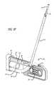
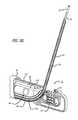
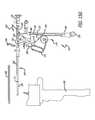
- FIG. 1is an elevation view, depicting an integrated anchor deployment device
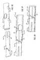
- FIG. 2Ais a cross-sectional view, depicting a distal end portion of the device of FIG. 1 ;
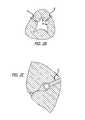
- FIG. 2Bis a cross-sectional view, depicting the implantation of anchor assemblies at an interventional site
- FIG. 2Cis an enlarged view, depicting one anchor component of the assemblies shown in FIG. 2B ;
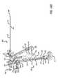
- FIG. 2Dis a partial perspective view, depicting an elongate tube assembly of the device of FIG. 1 without the outer sheath and detached from the nose assembly and handle assembly;
- FIG. 2Eis a cross-sectional view, depicting a portion of a handle assembly of the device of FIG. 1 ;
- FIG. 2Fis a cross-sectional view, depicting further details of the device of FIG. 2C in addition to a cross-sectional view of a portion of the tubular housing assembly;
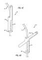
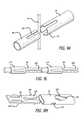
- FIG. 3Ais a perspective view, depicting a first anchor member of an anchor assembly of the present invention shown in a substantially straight configuration
- FIG. 3Bis a perspective view, depicting the first member of FIG. 3A in a deployed or flipped configuration
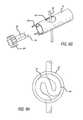
- FIG. 3Cis a perspective view, depicting a first component of a second anchor member of an anchor assembly of the present invention
- FIG. 3Dis a perspective view, depicting a second component of a second anchor member of an anchor assembly of the present invention.
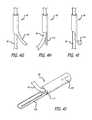
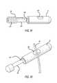
- FIG. 3Eis a perspective view, depicting a connector component with a plurality of first anchor members of the anchor assembly disposed thereon;
- FIG. 3Fis a perspective view, depicting an assembled anchor assembly
- FIG. 3Gis a perspective view, depicting a coined connector
- FIG. 3His a perspective view, depicting a connector equipped with raised portions
- FIG. 3Iis a perspective view, depicting a connector equipped with crimped components
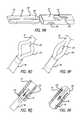
- FIG. 4Ais a perspective view, depicting an alternate embodiment of a distal component of an anchor assembly
- FIG. 4Bis a perspective view, depicting the distal component of FIG. 4A in a flipped configuration
- FIG. 4Cis a perspective view, depicting another alternate embodiment of a distal component of an anchor assembly
- FIG. 4Dis a perspective view, depicting the distal component of FIG. 4C in a flipped configuration
- FIG. 4Eis a perspective view, depicting yet another alternate embodiment of a distal component of an anchor assembly
- FIG. 4Fis a perspective view, depicting the distal component of FIG. 4E in a flipped configuration
- FIG. 4Gis a perspective view, depicting a distal component of an anchor assembly with a first embodiment of a tail section;
- FIG. 4His a perspective view, depicting a distal component of an anchor assembly with a second embodiment of a tail section;
- FIG. 4Iis a perspective view, depicting a distal component of an anchor assembly with a third embodiment of a tail section;
- FIG. 4Jis a perspective view, depicting yet another embodiment of a distal component
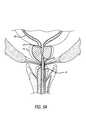
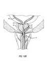
- FIG. 5Ais a cross-sectional view, depicting a first step of treating a prostate gland using the present invention
- FIG. 5Bis a cross-sectional view, depicting a portion of the anchor deployment device of FIG. 1 with the first actuator pivoted toward the handle assembly;
- FIG. 5Cis a cross-sectional view, depicting further internal mechanisms of the handle for accomplishing the advancement of the needle assembly
- FIG. 5Dis a perspective view, depicting the distal end portion of the anchor deployment device and the lateral advancement of a needle assembly
- FIG. 5Eis a cross-sectional view, depicting a second step of treating a prostate gland using the present invention.
- FIG. 5Fis a perspective view, depicting the partial retraction of the needle assembly
- FIG. 5Gis a cross-sectional view, depicting the assembly of FIG. 5D ;
- FIG. 5His a perspective view, depicting the complete retraction of the needle assembly
- FIGS. 5I and Jare cross-sectional views, depicting further steps of a method of treating a prostate gland using the present invention.
- FIG. 5Kis an enlarged perspective view, depicting one embodiment of a feeding mechanism for the distal component
- FIG. 6Ais an elevation view, depicting one alternative approach for controlling the advancement and deployment of an anchor component
- FIG. 6Bis an elevation view, depicting a first configuration of the anchor of FIG. 6A after release from the advancement substructure.
- FIG. 6Cis an elevation view, depicting a second configuration of the anchor of FIG. 6A after release from the advancement substructure.
- FIG. 6Dis a perspective view, depicting an alternate embodiment of a pusher device
- FIG. 6Eis a perspective view, depicting a needle and pusher assembly configured for side loading of an anchor component
- FIG. 6Fis a perspective view, depicting an alternate embodiment of a pusher assembly
- FIG. 6Gis a perspective view, depicting the pusher assembly of FIG. 6F and a complementary needle assembly
- FIG. 7Ais a cross-sectional view, depicting an anchor loaded in a protective cover
- FIG. 7Bis a cross-sectional view, depicting a pusher cartridge in a loaded position
- FIG. 7Cis a cross-sectional view, depicting the cartridge of FIG. 7A in an anchor deployed position
- FIG. 7Dis an elevation view, depicting an anchor cartridge assembly
- FIG. 7Eis a perspective view, depicting a needle assembly equipped with a sensor
- FIG. 8Ais a cross-sectional view, depicting the pivoting of the second actuator with respect to the handle
- FIG. 8Bis an isometric view, depicting internal components operatively associated with the second actuator and with other components of the anchor deployment device removed;
- FIG. 8Cis a partial cross-sectional view, depicting a distal end portion of the integrated anchor deployment device of FIG. 8A ;
- FIG. 8Dis a partial cross-sectional view, depicting the deployment device of FIG. 8C with a second component of the second anchor member being advanced toward a first component of the second anchor member;
- FIG. 8Eis a perspective view, depicting the deployment device of FIG. 8B with the second component completely advanced into locking engagement with the first component;
- FIG. 9Ais an enlarged perspective view, depicting a first step in joining the first and second components of the second anchor member
- FIG. 9Bis an enlarged perspective view, depicting a second step in joining the first and second components of the second anchor member
- FIG. 9Cis an enlarged perspective view, depicting a third step in joining the first and second components of the second anchor member
- FIG. 9Dis an enlarged perspective view, depicting a first step in an alternate approach in joining the first and second components of the second anchor member;
- FIG. 9Eis an enlarged perspective view, depicting a second step in the alternate approach in joining the first and second components of the second anchor member;
- FIG. 9Fis an enlarged perspective view, depicting a third step in the alternate approach in joining the first and second components of the second anchor member;
- FIG. 9Gis a perspective view, depicting another alternate embodiment of the first and second components of the second anchor member
- FIG. 9His a cross-sectional view, depicting an interior of the assembly shown in FIG. 9G ;
- FIG. 9Iis a perspective view, depicting yet another alternative embodiment of the first and second components of the second anchor member
- FIG. 9Jis a perspective view, depicting yet another embodiment of the second anchor member.
- FIG. 9Kis a perspective view, depicting a further embodiment of the second anchor member
- FIG. 9Lis a perspective view, depicting yet a further embodiment of the second anchor member
- FIG. 9Mis a perspective view, depicting another embodiment of the second anchor member
- FIG. 9Nis a perspective view, depicting another embodiment of the second anchor member
- FIG. 9Ois a perspective view, depicting another embodiment of the second anchor member
- FIG. 9Pis a perspective view, depicting the embodiment of FIG. 9O in an assembled form
- FIG. 9Qis a perspective view, depicting another embodiment of the second anchor member
- FIG. 9Ris a perspective view, depicting the embodiment of FIG. 9Q in an assembled form
- FIG. 9Sis a perspective view, depicting another embodiment of the second anchor member.
- FIG. 9Tis a perspective view, depicting another embodiment of the second anchor member
- FIG. 9Uis a perspective view, depicting the embodiment of FIG. 9T in an assembled form
- FIG. 9Vis a perspective view, depicting another embodiment of the second anchor member
- FIG. 9Wis a perspective view, depicting the embodiment of FIG. 9V in an assembled form
- FIG. 9Xis a perspective view, depicting another embodiment of the second anchor member
- FIG. 9Yis a perspective view, depicting another embodiment of the second anchor member
- FIG. 9Zis a perspective view, depicting another embodiment of the second anchor member
- FIG. 9 AAis a perspective view, depicting another embodiment of the second anchor member
- FIG. 9 ABis a perspective view, depicting another embodiment of the second anchor member
- FIG. 9 ACis a perspective view, depicting the embodiment of FIG. 9 AC in a compressed form
- FIG. 9 ADis a perspective view, depicting another embodiment of the second anchor member
- FIG. 9 AEis a perspective view, depicting the embodiment of FIG. 9 AD in a compressed form
- FIG. 9 AFis a perspective view, depicting another embodiment of the second anchor member
- FIG. 9 AGis a perspective view, depicting another embodiment of the second anchor member
- FIG. 9 AHis a perspective view, depicting the embodiment of FIG. 9 AG in an open configuration
- FIG. 9 AIis a perspective view, depicting another embodiment of the second anchor member in combination with a forming anvil
- FIG. 9 AJis a perspective view, depicting another embodiment of the second anchor member in combination with a forming anvil
- FIG. 9 AKis a perspective view, depicting another embodiment of the second anchor member
- FIG. 9 ALis a perspective view, depicting another embodiment of the second anchor member
- FIG. 9 AMis a perspective view, depicting the embodiment of FIG. 9 AL in an open configuration
- FIG. 9 ANis a perspective view, depicting another embodiment of the second anchor member shown in its flattened configuration
- FIG. 9 AOis a perspective view, depicting another embodiment of the second anchor member shown in its flattened configuration
- FIGS. 10A-Bare cross-sectional views, depicting yet further steps involved in treating a prostate gland using the present invention.
- FIG. 11Ais a cross-sectional view, depicting a first step in an alternative approach to anchor assembly and deployment;
- FIG. 11Bis a cross-sectional view, depicting a second step in an alternative approach to anchor assembly and deployment;
- FIG. 11Cis a cross-sectional view, depicting a third step in an alternative approach to anchor assembly and deployment;
- FIG. 12Ais a perspective view, depicting structure configured to align components of the anchor assembly
- FIG. 12Bis a cross-sectional view, depicting the structure of FIG. 12A ;
- FIG. 13Ais a partial cross-sectional view, depicting a first step in an alternative approach to implanting an integrated anchor assembly
- FIG. 13Bis a partial cross-sectional view, depicting a second step in an alternative approach to implanting the integrated anchor assembly of FIG. 13A ;
- FIG. 13Cis a perspective view, depicting a third step in an alternative approach to implanting the integrated anchor assembly of FIG. 13A ;
- FIG. 13Dis a perspective view, depicting yet another embodiment of an integrated anchor
- FIG. 13Eis an elevation view, depicting the anchor of FIG. 13D in a flipped configuration
- FIG. 13Fis an elevation view, depicting the anchor of FIG. 13D in a flat configuration.
- FIG. 14Ais a perspective view, depicting one preferred embodiment of a first anchor member of an anchor assembly of the present matter
- FIG. 14Bis a side view, depicting the first anchor member of FIG. 14A attached to a connecting member;
- FIG. 14Cis a perspective view, depicting components of one of the preferred embodiments of the second anchor member in a configuration prior to assembly;
- FIG. 14Dis a perspective view, depicting an assembled second anchor member of the present invention attached to a connecting member
- FIG. 15Ais a perspective view, depicting an alternate embodiment of an integrated anchor deployment device
- FIG. 15Bis a perspective view, depicting the device of FIG. 15A with an outer handle casing removed;
- FIG. 15Cis a side view, depicting the device of FIG. 15B with an outer sleeve removed;
- FIG. 15Dis a side view, depicting the device of FIG. 15C with a top mount trigger depressed
- FIG. 15Eis a side view, depicting the device of 15 D with the top mount trigger further depressed
- FIG. 15Fis a side view, depicting the device of FIG. 15B with a second trigger in a default position
- FIG. 15Gis a side view, depicting the device of FIG. 15F with the second trigger in a depressed position
- FIG. 15His a side view, depicting an alternate embodiment of the device depicted in FIG. 15B .
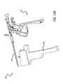
- FIG. 16Ais a perspective view, depicting yet another embodiment of an integrated anchor delivery device
- FIG. 16Bis a perspective view, depicting the integrated anchor delivery device of FIG. 16A with a first cover removed;
- FIG. 16Cis a perspective view, depicting the integrated anchor delivery device of FIG. 16B with a second cover removed;
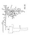
- FIG. 16Dis a perspective view, depicting the device of FIG. 16C rotated 180 degrees;
- FIG. 16Eis a perspective view, depicting the device of FIG. 16D with a first trigger activated
- FIG. 16Fis a perspective view, depicting the device of FIG. 16C with a second trigger activated.
- FIG. 16Gis a perspective view, depicting the device of FIG. 16F with an upper lever activated.
- the present inventionis embodied in a device configured to deliver anchor assemblies within a patient's body.
- the present inventioncan be employed for various medical purposes including but not limited to retracting, lifting, compressing, supporting or repositioning tissues, organs, anatomical structures, grafts or other material found within a patient's body. Such tissue manipulation is intended to facilitate the treatment of diseases or disorders.
- the disclosed inventionhas applications in cosmetic or reconstruction purposes or in areas relating the development or research of medical treatments.
- the anchor assembly of the present inventionis contemplated to be formed of a structure which is visible by ultrasound. Accordingly, the anchor assembly can be viewed during ultrasonic body scans such as during normal trans-rectal ultrasound when a medical professional is conducting diagnoses or treatment associated with conditions like prostate cancer.
- one portion of an anchor assemblyis positioned and implanted against a first section of anatomy.
- a second portion of the anchor assemblyis then positioned and implanted adjacent a second section of anatomy for the purpose of retracting, lifting, compressing, supporting or repositioning the second section of anatomy with respect to the first section of anatomy.
- both a first and second portion of the anchor assemblycan be configured to accomplish the desired retracting, lifting, compressing, supporting or repositioning of anatomy due to tension supplied thereto via a connector assembly affixed to the first and second portions of the anchor assembly.
- an integrated anchor delivery device 20is configured to include structure that is capable of both gaining access to an interventional site as well as assembling and implanting an anchor device, anchor assembly within a patient's body.
- the devicefurther includes structure configured to receive a conventional remote viewing device (e.g., an endoscope) so that the steps being performed at the interventional site can be observed.
- a conventional remote viewing devicee.g., an endoscope
- the integrated anchor delivery device 20includes a handle assembly 22 and a tubular housing assembly 24 extending from the handle assembly 22 .
- the handle assembly 22is sized and shaped to fit comfortably within an operator's hand and can be formed from conventional materials.
- the proximal end of the delivery device 20includes a mount 26 for receiving an endoscope or telescope 28 or other imaging device.
- the mount 26includes an internal bore (not shown) sized and shaped to receive the telescope 28 .
- the telescope 28is intended to provide the operator with the ability to view the operation of the delivery device 20 at an interventional site.
- the handle assembly 22 of the delivery device 20also includes a plurality of activators or triggers associated with the handle assembly 22 .
- the body 30includes a first or upper portion 32 extending generally perpendicularly with respect to a second or lower portion 34 .
- the second portionis intended to be sized and shaped to fit within the palm of an operator's hand.
- Pivotably affixed to the second portion 34is a first actuator 36 .
- the first actuator 36includes a hooped portion sized and shaped to receive one or more fingers of the operator's hand.
- the hooped portionextends from an arm which is pivotably connected to the handle 22 , the arm and hooped portion defining an acute angle with respect to the second portion 34 of the handle assembly 22 when inactivated.
- the first actuator 36is operatively associated with a needle assembly and structure configured to advance and place a first component of an anchor assembly at an interventional site.
- a second trigger or actuator 38is pivotably connected adjacent the first body portion 32 .
- the second actuator 38defines a generally finger-like projection and is positioned longitudinally distally from the body 30 with respect to the first actuator 36 .
- the second actuator 38also defines an acute angle respecting the second portion 34 of the handle assembly 22 and is sized and shaped to comfortably receive one or more fingers of the operator.
- the second actuator 38is configured to accomplish the assembly of an anchor device by attaching a second anchor component to a connector affixed to the first anchor component.
- a third trigger or actuator 40is connected and configured to pivotably rotate with respect to a top side of upper body portion 30 .
- the third actuator 40defines a relatively straight member with a rounded substructure formed at its free terminal end. In this way, the third actuator 40 is easily manipulated by a free digit of the operator's hand.
- the third actuator 40rotates from a forward position where it forms an acute angle with the tubular housing assembly 24 to a rearward position where the member defines an obtuse angle with respect to the tubular housing assembly 24 .
- the third actuator 40is intended to retract portions of the tubular housing assembly 24 as well as accomplish cutting the connector of the anchor assembly and deploying the anchor assembly at an interventional site.
- the tubular housing assembly 24extends from the handle assembly 22 .
- the tubular housing assembly 24is mounted to a front face of the upper portion 32 of the handle assembly 22 and extends parallel to a longitudinal axis of the upper portion 32 .
- the tubular housing assembly 24includes a mount 42 from which an outer sheath 44 extends in a distal direction.
- the mount 42includes one or more conventional stop cock assemblies 46 which provide fluid communication with an interior of the tubular housing assembly.
- One stop cock assembly 46is intended to provide the anchor delivery device 20 with a continuous flow irrigation.
- Another stop cock 46is contemplated to be used to accomplish a suction function through the device. Either of these assemblies can further be employed to deliver therapeutic or diagnostic substances to the interventional site.
- substances that cause the prostate to decrease in sizesuch as 5-alpha-reductase inhibitors can be introduced at the treatment site.
- Other substances but not limited thereto, which may be introduced at the siteinclude various scarring agents, rapamycin and its analogues and derivatives, paclitaxel and its analogues and derivatives, phytochemicals, alpha-1a-adrenergic receptor blocking agents, smooth muscle relaxants and other agents that inhibit the conversion of testosterone to dihydrotestosterone.
- a terminal end portion 48 of the tubular housing assembly 24 of the anchor deployment device 20includes a nose assembly 50 shaped to provide an atraumatic surface as well as one which facilitates desired positioning of components of an anchor assembly (See FIG. 2A ). That is, by including structure that can mimic the ultimate position of a proximally oriented component of an anchor assembly, an operator can test the effect of the anchor assembly prior to implantation. Once the operator confirms that the subject anchor component will be positioned as desired, the implantation of the anchor is then undertaken and accomplished.
- the anchor assembly 51(See FIGS. 2B and C) of the present invention accomplishes desired tissue manipulation, compression or retraction as well as cooperates with the target anatomy to provide an atraumatic support structure.
- the shape and contour of the anchor assembly 51can be configured so that the assembly invaginates within target tissue, such as within natural folds formed in the urethra by the opening of the urethra lumen by the anchor assembly.
- target tissuesuch as within natural folds formed in the urethra by the opening of the urethra lumen by the anchor assembly.
- wispy or pillowy tissue in the areacollapses around the anchor structure.
- the natural tissuecan grow over the anchor assembly 51 and new cell growth occurs over time in the areas shown in FIG. 2C .
- Such cooperation with target tissuefacilitates healing and avoids unwanted side effects such as calcification at the interventional site.
- Manners in which healing can be promotedcan include employing abrasive materials, textured connectors, biologics and drugs.
- one portion of an anchorcan be placed within an urethra. It has been found that configuring such anchors so that ten o'clock and two o'clock positions (when looking along the axis of the urethra) are supported or retained, effectively holds the anatomy open and also can facilitate invagination of the anchor portion within natural tissue. This is particularly true in the regions of anatomy near the bladder and the juncture at which the ejaculatory duct connects to the urethra.
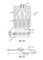
- the terminal end portion 48( FIG. 2A ) includes a plurality of spring biased, vertically stacked ring anchor components 52 strategically positioned with respect to telescoping structure of the tubular housing assembly for the purpose of assembling an anchor device.
- the stacked anchor component 52is one of two parts which form a second anchor component.
- a leaf spring 54is placed in apposition with the anchor component 52 that is at the bottom of the stack of components.
- Internal molded walls and bosses of the nose assembly 48form a space to both receive the stacked anchor components 52 as well as provide an area to retain the leaf spring 54 and provide a base structure against which force supplied by the leaf spring can be generated and transmitted to the anchor components 52 .
- FIG. 2Aterminal end portions of an upper tubular member 56 , a needle housing 58 and a telescope housing 60 are positioned within the nose assembly.
- FIG. 2Done can better see the internal components forming the tubular housing assembly.
- the outer sheath 44is not depicted in FIG. 2A and the internal components of the tubular housing assembly are shown separate from the nose assembly and handle assembly.
- the upper tubular member 56 , the needle housing 58 and telescope housing 60extend longitudinally.
- the outer sheath(not shown in FIG. 2A ) covers a substantial length of each of the upper tubular member 56 , needle housing 58 and telescope housing 60 .
- Each of these structuresalso include internal bores, the upper tubular member 56 sized to slideably receive a pusher assembly (described in more detail below) and the needle housing 58 sized to slideably receive a needle assembly 58 (also described in more detail below).
- the telescope housing 60is sized to receive a conventional telescope (not shown), which in one approach, fills the entire space provided by the internal bore of the housing 60 .
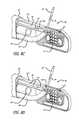
- a cross-sectional view of a portion of the tubular housing assembly attached to the handle assembly 22 (with the nose assembly removed)is shown in FIG. 2F .
- the handle assembly 22houses a needle assembly advancement and retraction subassembly 66 that interacts with the movement of the first actuator.
- the first actuatorincludes a projection 68 extending through the housing assembly 22 and is placed in operative association with the advancement and retraction subassembly 66 .
- the needle assembly advancement and retraction subassembly 66includes an outer collar 70 configured about an inner collar 72 . Configured between the outer collar 70 and an internal front surface 74 of the handle assembly 22 is a first compressor spring 75 . Placed within the outer collar 68 and between the inner collar 72 and an internal front surface 76 is a second compression spring 77 . Additionally, attached to the outer collar 70 is a lock assembly 78 which rotates between locked and unlocked positions.
- the compression springs 75 , 76assume expanded configurations (See FIGS. 2E and F). Also, the lock assembly 78 is in a disengaged or unlocked configuration. It is at this stage that the needle assembly (described below) is in its retracted state and housed completely within the needle housing 58 .
- FIGS. 3A and 3BOne preferred embodiment of a first or distal component 82 is shown in FIGS. 3A and 3B .
- the first componentforms a generally T-configuration ( FIG. 3B ).
- the first componentdefines a substantially straight member ( FIG. 3A ).
- the componentcan be formed from a number of materials and manufactured using various conventional approaches, it is contemplated that the component 82 be cut from a nitinol tube using a laser. Using a superelastic material such as nitinol provides the component 82 with the resiliency to transform between a flipped T-configuration and a straight configuration.
- the first component 82includes a first portion 84 which at one end defines a cylindrical structure and at the other a partial cylindrical structure. When unconstrained, this first portion 84 forms a T-bar or top of the first component 82 .
- a complementary partial cylindrical structureforms a mid-section or second portion 86 of the first component 82 and operates as a spring to accomplish the flipping of the first portion 84 between constrained and unconstrained configurations. When the component is in its constrained, straight form, the second portion is positioned adjacent the first portion 84 .
- a third portion 88is also cylindrical in shape and extends from the second portion 86 away from the first portion 84 of the first anchor component 82 . The third portion 88 slides freely with respect to a connector, the connector being attached to the first portion 84 and a second anchor component as will be described below.
- FIG. 3COne part of the second anchor component 52 is best seen in FIG. 3C (previously depicted as stacked anchor components in FIG. 2A ).
- This componentis generally cylindrical in form and includes integrally formed rings 90 spaced along an outer surface of the device, such spacing can be varied as necessary for a particular purpose.
- the devicefurther includes a internal bore 92 which extends the entire length thereof.
- a proximal end 93 of this part of the second anchor component 52includes an opening to the internal bore 92 .
- the opening to the bore 92is surrounded by a first ring 90 and is sized to receive in a locking arrangement the connector which will attach the first anchor 82 to the second anchor component 52 .
- Additional rings 90are spaced longitudinally along an outside surface of the component.
- a second part 98 of the second anchor component 52can be sized and shaped to both engage a connector and to lockingly engage the first part.
- the second partis generally cylindrical and includes a pair of spaced arms, the outer profile being sized to fit within the internal bore 92 of the first part.
- the connector 94can be formed from any material which provides the desired holding force between first and second components.
- the connectoris formed from conventional connector material for example monofilament polyester.
- the connector 94is monofilament polyethylene terephthalate (PET).
- PETpolyethylene terephthalate
- the connector materialembodies desirable flexibility as well as tensile strength.
- the monofilament PET size 2-0is preferred because of high tensile strength when tensioned and high column strength to push the series of parts 82 through and out the needle.
- the monofilamenthelps reduce or eliminate the possibility of infection.
- first anchor components 82can be affixed along a length of the connector 94 .
- various approachescan be employed to attach a first anchor component 82 to the connector.
- the componentscan be affixed by an adhesive or can include tabs or other structure which is deformed into a locking arrangement with the connector 94 .
- the anchor component 82can simply be crimped directly to the connector 94 or the connector itself can include structure which is complementary to that of the component to accomplish affixation. It may be advantageous to employ an assembly capable of handling a connector equipped with a plurality of anchor components spaced along the connector since such a system has the ability to assemble and deliver multiple anchor assemblies without needing to reload.
- FIG. 3FOne embodiment of a completely assembled anchor assembly 92 is depicted in FIG. 3F .
- the assemblyincludes a single first anchor component 82 .
- the completed anchor assemblyis formed from components which are held together magnetically.
- the first anchor component 82 and the second anchor component 52 , 98can be held in place through magnetism and without the need of a connector.
- either both or one of the anchor componentscan be a magnet.
- the second anchor componentembodies the first part 52 which can be deployed from the stacked group of such members housed within the terminal end portion 48 of the tubular housing assembly 24 (See FIG. 2A ), as well as the second part 98 which, by operation of the anchor delivery device 20 (described below), lockingly engages the first part 52 .
- a completed anchor assembly 96can be employed to manipulate tissue and other structure found within a patient's body for various purposes.
- the first anchor component 82is initially positioned in an apposition with a first body structure, such as the outer surface of the prostate capsule, and the second anchor component assembly ( 52 , 98 ) is placed against a second body structure, such as the inner surface of the urethra, the connector 94 holding the desired spacing between the two body structures to accomplish the desired manipulation.
- all components of the anchor assembly 96 or selected portions thereofmay be coated or embedded with therapeutic or diagnostic substances (e.g. drugs or therapeutic agents).
- therapeutic or diagnostic substancese.g. drugs or therapeutic agents.
- the anchor assembly 96can be coated or imbedded with substances such as 5-alpha-reductase which cause the prostate to decrease in size.
- substances contemplatedinclude but are not limited to phytochemicals generally, alpha-1a-adrenergic receptor blocking agents, smooth muscle relaxants, and agents that inhibit the conversion of testosterone to dihydrotestosterone.
- the connector 95can for example, be coated with a polymer matrix or gel coating which retains the therapeutic or diagnostic substance and facilitates accomplishing the timed release thereof.
- bacteriostatic coatingscan be applied to various portions of the anchor assemblies described herein. Such coatings can have various thicknesses or a specific thickness such that it along with the connector itself matches the profile of a cylindrical portion of an anchor member affixed to the connector.
- the co-delivery of a therapeutic or diagnostic gel or other substances through the implant deployment device or another medical device (i.e. catheter), and moreover an anchor assembly including the sameis contemplated.
- the deployment deviceincludes a reservoir holding the gel substance and through which an anchor device can be advance to pick up a desired quantity of therapeutic or diagnostic gel substance.
- the connector 94can have associated therewith various structures which facilitate the attachment of anchor structures. Although intended for the first anchor component 82 , such structure can also be used for the second anchor component 52 , 98 . In one approach ( FIG. 3G ), the connector 94 is coined 100 in a manner that provides structure to which an anchor member can form a locking engagement. As shown in FIG. 3H , structure facilitating a locking engagement with anchor structure also can also be in the form of a ball-chain 102 . Furthermore, a connector 94 can be equipped with crimped metal or other structures 104 for this purpose.
- FIGS. 4A-4Ivarious alternatives of first anchor components 82 are presented.
- those depicted in FIGS. 4A-Ieach include a structure which flips to assume an angled or generally lateral configuration when the component is unconstrained. In a constrained configuration, these components define a generally cylindrical profile (as shown in FIG. 4A ).
- each of the various alternative embodimentscan be formed from conventional materials.
- the componentscan be formed by laser cutting a nitinol tube.
- EDMelectrospray diffraction
- the connector shown in FIG. 4Aincludes a proximally oriented collar 106 which is intended to be slid along a connector as the second portion flips or rotates.
- a spring member 86defines a bar arm which forms a bridge between the collar 106 and a second portion 108 which flips or rotates with respect to the collar 106 when the device is unconstrained as shown in FIG. 4B .
- the spring member 86forms a bridge between the collar 106 and a second portion 108 which includes a pair of members which in a constrained configuration extend in opposite directions along the connector 94 and when unconstrained, form a T-bar structure.
- FIGS. 4C and 4Dthe spring member 86 forms a bridge between the collar 106 and a second portion 108 which includes a pair of members which in a constrained configuration extend in opposite directions along the connector 94 and when unconstrained, form a T-bar structure.
- the anchor component 82can include a pair of collars 106 configured between which are first and second springs 86 . Attached to each spring 86 is a second portion 108 , each of which assume angled or lateral positions to thereby form an overall cross-like structure when unconstrained. Like the other embodiments, the component defines a generally straight, cylindrical structure when constrained.
- FIGS. 4G-Idepict further embodiments of structures that can be employed as first anchor components 82 or alternatively, can be used solely as structures for advancing the anchor assembly sub-components within the anchor delivery device or a patient's body.
- Each of these depicted structuresinclude various forms of tails 110 which can be employed to advance the anchor components 82 through direct engagement with a terminal end of a pusher assembly (not shown) or for registering within slots formed in a pusher assembly. These tails also help to flip, turn or angle the component 82 relative to connector 94 .
- One embodiment of the tail( FIG. 4G ) is a simple extension of a partial cylindrical member which is bent away from the connector 94 . Another approach ( FIG.
- FIG. 4Hinvolves a long tail 110 which is folded against the connector 94 and yet another approach ( FIG. 4I ) involves a tail 110 that rather than folded against the connector includes a narrowed section which is bent away from the connector and terminates to assume a beaver tail-like shape.
- the first anchor componentincludes a full tube portion 107 connected to a half tube portion 109 by a coiled portion 111 .
- the devicecan further include connector attachment points formed along the full tube portion 109 .
- the coiled portion 111provides flexibility in multiple planes and thus facilitates pushing the device through bends or angles formed in the deployment device employed to deliver the first anchor component 82 .
- the telescope deviceis employed to view the positioning of the device 20 at the interventional site, for example, the tubular housing assembly 24 of the device is inserted into the penis of a patient and advanced until the distal end 48 is adjacent an interventional site in the urethra (UT) adjacent the bladder (UB; See FIG. 5A ).
- UTurethra
- Uurethra
- the present inventionalso contemplates steps for sizing the anatomy.
- the present inventionalso involves the placement of an ultrasonic or other device in the patient's body, such as in the rectum, to measure the necessary depth of insertion of the anchor deployment device within the patient's body.
- This informationcan be used to set or create a depth stop for the needle assembly so that the operator can readily determine whether desired sections of the patient's anatomy have been accessed.
- the first actuator 36 of the delivery device 20See FIG. 1
- the handle assembly 22is then caused to be pivoted towards the handle assembly 22 . Doing so causes the needle assembly 112 to be advanced distally and then laterally through a terminal end of the needle housing 58 .
- the lock assembly 78retains the needle in the advanced configuration (See FIGS. 5C and D).
- the lock assembly 78can be configured to automatically unlock or to require manipulation to disengage from a locking position.
- the needle assembly 112is advanced through the prostate gland to a first implant position (See FIG. 5E ).
- first forked member 113is translatable longitudinally either by hand or through action of a trigger or activator.
- FIG. 5Dthe first forked member 113 is shown retracted to more easily represent other system components, but in use, at this stage of deployment, the member 113 is contemplated to be in an advanced position into engagement with slot 115 .
- second forked member 119is shown in a truncated form, in that at this stage of deployment the terminal end of the member 119 extends beyond the vertical stack of second anchor components 52 , thereby holding the stack in a staged configuration.
- the present inventionalso contemplates a single member replacing the forked members 113 , 119 depicted, such a part of member 56 which can have portions which provide the function accomplish by the terminal ends of the members 113 , 119 .
- the needle assembly 112has a generally tubular shape and terminates with a sharp point 114 .
- a lumen extending the length of the needle assembly 112is sized to receive both components of the anchor assembly as well as structure for advancing the assembly through and out of the terminal end 114 .
- the needle assembly 112is intended to be formed from resilient material such as nitinol or other materials or polymeric substances.
- the needle housing 58includes a distal section angled such that the needle projects at angles approaching or at 90 degrees with respect to a longitudinal axis of the tubular housing assembly 24 .
- the actuatoris further manipulated to release the lock assembly 78 as well as to cause the internal compression springs to retract the needle assembly.
- the position of the first actuator 36will return to the open position (See FIGS. 1 , 2 E and 2 F).
- the result of this actionis depicted in FIGS. 5F , G, H, I and J. (Again, note that member 113 and 119 are shown in retracted or truncated forms in FIGS.
- the advancing structureis in the form of a pusher assembly 116 .
- the pusher 116can assume a generally cylindrical tube formed form a metallic or polymeric material which is sized and shaped to directly engage the first anchor component 82 .
- the pusher 116could define a solid elongate member of polygonal or circular cross-section. Also, it can be configured to directly engage the connector 94 directly or other structure formed on the connector 94 (See FIGS. 3G-I ).
- the pushercan be sized to surround the first anchor member 82 and to engage a tail (See FIGS. 4G-I ) for example, of the anchor member once the pusher is pulled proximally with respect to the anchor member.
- a tailSee FIGS. 4G-I
- the pusher 116initially surrounds the anchor member (or other structure formed directly on the connector 94 )
- the tailis held in compression, only to be released to extend laterally from the connector when the pusher is moved proximally.
- the pusher assembly 116can both be withdrawn when desired and advance the anchor member 82 and connector structure 94 when necessary.
- the tailcan be held in compression by the internal surface of the needle (not shown).
- the complete withdrawal of the pusher 116 and needle assembly 112exposes the full length of connector anchor structure for use in ultimately manipulating anatomical structures.
- Such complete withdrawalinvolves both the pusher 116 and needle assembly to be housed completely within the needle housing 58 .
- the delivery devicecan be equipped with a pusher member 116 in combination with a pull wire 118 .
- the pusher member 116 in this approachremains proximal an anchor member 82 to be advanced along the delivery device.
- Such anchor members 82can be placed in a position distal the pusher, for example, by being released from a cartridge configured distal to the pusher position or the delivery device can be a single use apparatus.
- the anchor member 82can include a proximal portion characterized by a pair of elastically or plastically deformable arms 120 which in a first configuration are held to the pull wire 118 and in a second configuration, are released from the pull wire 118 . Accordingly, the pusher member 116 is advanced with respect to the pull wires 118 to cause the arms 120 to become disengaged from the pull wire.
- the arms 120are plastically deformable whereas the arms 120 of the anchor member 82 of FIG. 6C are elastically deformable.
- the elastically deformable arms 120can be formed from resilient material such as nitinol.
- the plastically deformable arms 120on the other hand can be made from less resilient material.
- FIGS. 6D-GFurther alternative embodiments of pusher members 116 are shown in FIGS. 6D-G .
- a pusher member 118 having a D-shaped cross-sectional profileis contemplated for certain uses. Such a profile enables the pusher member 116 to be placed along side the anchor component 82 and connector 94 assembly, a distal portion of the D-shaped configuration engaging complementary structure on the connector assembly.
- a pusher assembly 116which includes a side opening 122 in communication with a lumen extending through the pusher 116 (See FIG. 6E ). Threaded through the side opening 122 is a distal portion of the anchor component 82 and connector 94 assembly. In this arrangement, the distal-most anchor component 82 is placed against the terminal end of the pusher member 116 to accomplish advancement of the anchor component 82 and connector 116 assembly as the pusher 116 is extended distally.
- the pusher member 116includes a terminal end 123 configured with a D-shaped profile suited to engage and advance an anchor/connector assembly 94 .
- a proximal section of the pusher 116is equipped with a plurality of spaced detents or cavities 124 sized and shaped to receive anchor components 82 or other structure formed on the connector 94 .
- the pusher member 116is configured to reside longitudinally adjacent the anchor/connector assembly 82 , 94 . Advancement of the anchor/connector assembly 82 , 94 is accomplished through an engagement between certain of the anchor/connector assemblies 82 , 94 and the cavities 124 .
- a first stepthe anchor member 82 is loaded within an anchor protection cover 126 ( FIG. 7A ).
- a pusher member 116is configured proximal to the connector 94 of the first anchor member 82 to accomplish advancement of the first anchor member 82 into and through the needle assembly 112 (See FIGS. 7B and C).
- This subassemblyis insertable within a delivery device bay 128 .
- a distal portion 130 of an interior of the delivery device bayis equipped with a conical taper configured to receive a distal complementary portion of the anchor protection cover 126 thereby accomplishing the centering of anchor member within the delivery bay 128 .
- An internal lumenextends the length of the protection cover 126 and the cover 126 includes a ring seal 132 placed within a proximal end thereof. The ring seal 132 functions to hold the cover 126 on a pusher member 116 .
- the delivery device bay 128can further include a bayonet lock mount 134 that couples a spring loaded cartridge 136 to the delivery device bay 128 .
- a compression spring 138housed within the cartridge is a compression spring 138 configured about the pusher member 116 .
- the spring cartridge 138can also include a lock-out structure 140 which operates to limit the tension placed on the anchor member 82 and connector 94 until the needle 112 is withdrawn sufficiently from the interventional site to avoid damage from the needle 112 inadvertently engaging the anchor/connector assembly 82 , 94 .
- the pusher 116includes a proximal end configured with an anchor deployment tab 142 that engages the lock-out structure 140 , prohibiting the compression spring 138 from applying tension to the anchor/connector assembly 82 , 94 before the needle assembly 112 is clear of the interventional site.
- the anchor delivery devicecan be fashioned with a multi-shooter anchor cartridge assembly 144 .
- a manifold 146including four entries which feed into a lumen extending into a needle assembly 112 , each entry configured to receive one anchor/connector assembly 82 , 94 .
- Proximal sections of the connector 94are configured into spools 148 which are driven by a torsional spring drive shaft 150 .
- the drive shaft 150is in turn, configured with complementary teeth structures 154 formed on each spool.
- the assemblyfurther includes structure (not shown) adapted to cause lateral movement in the driveshaft 150 so that its teeth 152 indexes from spool to spool 148 to thereby turn the spools 148 and advance the anchor members 82 within the needle assembly 112 .
- structure(not shown) adapted to cause lateral movement in the driveshaft 150 so that its teeth 152 indexes from spool to spool 148 to thereby turn the spools 148 and advance the anchor members 82 within the needle assembly 112 .
- the anchor delivery devicecan include the ability to detect forces being applied thereby or other environmental conditions.
- sensors 156can be placed along the needle assembly 112 . In this way, an operator can detect for example, whether the needle has breached the target anatomical structure at the interventional site and the extent to which such breaching has occurred.
- Other sensors which can detect particular environmental featurescan also be employed such as blood or other chemical or constituent sensors.
- one or more pressure sensors or sensors providing feedback on the state of deployment of the anchor assembly during delivery or after implantationare contemplated. For example, tension or depth feedback can be monitored by these sensors. Further, such sensors can be incorporated into the anchor assembly itself, other structure of the deployment device or in the anatomy.
- FIG. 8Bwhich depicts internal components of the integrated anchor assembly associated with the second actuator (other structure being removed for better understanding), as the second actuator 36 is depressed, it engages a lever assembly 120 including a slotted portion 122 to drive a rack assembly 124 distally.
- the slotted portion 122 of the lever assembly 120provides the lever with the ability to both rotate with respect to a mount 126 of the rack assembly 124 as well as advance the mount 126 as well as the rest of the rack assembly 124 distally.
- Various pawls 130are provided to releasably lock the rack assembly 124 in desired stages of advancement. It is to be recognized, however, that various other approaches to manually locking or unlocking structure for advancing components of the second anchor assembly are contemplated.
- the rack assembly 124is in turn, connected to a telescoping pusher member which is configured to engage a second part of the second or proximal anchor assembly.
- depressing the second actuator 38causes a pusher 157 to advance a second part 98 of the second or proximal anchor member to be advanced towards and into locking engagement with the first part 52 of the second anchor member.
- the second part 98captures the connector structure 94 and retains it in a locking engagement between the first 52 and second 98 parts.
- the connector 94is severed to thereby accomplish the formation of the complete anchor assembly (See FIG. 3E ).
- the severingcan be effected by the advancement of the telescoping pusher member via the depression of the second actuator 38 .
- the severing actionis operatively associated with the actuation of the third actuator 40 .
- the second actuator 38is released, automatically or manually, to permit the re-staging of both the first 52 and second 98 parts of the second anchor member. That is, in one contemplated approach, members 113 and 119 are withdrawn to allow the release and deployment of the second anchor member 52 , 98 and then advanced again after the desired staging of component 52 .
- the present inventionalso contemplates a myriad of alternative embodiments of the proximal or second anchor member.
- the second anchor memberis comprised of a first part 52 which is placed into a locking engagement with a second part 98 .
- the first 52 and second parts 98are affixed to the connector 94 .
- the first and second partscan be formed of any conventional materials such as metals or polymeric materials.
- the second anchor memberincludes a generally tubular first part 52 including a slightly flared mouth configured to receive both a portion of the connector 94 and a second part 98 .
- the second partincludes a pair of spaced arms 158 which capture the connector and facilitates advancing the connector within the mouth of the first part. It is contemplated that the arms 158 are spaced to an extent greater than an interior of the tubular first part 52 so that in combination with the area occupied by the connector 94 , a locking engagement between the first and second parts is accomplished upon the full insertion of the second part 98 within the first part 52 . Thereafter, excess connector 94 length can be cut away to form a complete second anchor assembly.
- the second part 98includes a spike-like terminal end portion 160 which can be configured to engage the connector 94 and insert it within an interior of a tubular first part 52 .
- the spike-like terminal end portion 160defines a tapered structure, a section with an enlarging dimension of which is sized and shaped to lockingly engage with the interior of the first part 52 .
- the completed assemblyis characterized by a portion of the connector 94 retained between the first 52 and second parts 98 .
- the connector 94is arranged to be threaded through a pair of oppositely arranged apertures 162 formed in a generally tubular first part 52 .
- the first part 52further includes a mouth equipped with a plurality of proximally oriented, radially spaced arms 164 .
- the second part 98also defines a generally tubular structure, one having a section with a smaller outer profile than an interior of the first part 52 .
- the second part 98further includes a pair of distally oriented projections 166 as well as a back end equipped with a gear-like collar 168 .
- the second part 98is inserted within the first part 52 so that the projections 166 are configured on opposite sides of the connector.
- the collar 168is then used to rotate the second part 98 with respect to the first part until the connector 94 defines an S-shaped portion within an interior of the first part.
- the second part 98is thereafter fully inserted into the first part, the gear-like collar being configured to register between the radially spaced arms 164 of the first part 52 to thereby lock the two parts to each other.
- these structures of the first 52 and second 98 partscan be reversed in that the first part 52 can assume the structure of the described second part and vice versa.
- each of these embodimentstake a similar approach to that shown in FIGS. 9G and H. That is, each take advantage of a locking engagement resulting from the rotation of one part of the second anchor member with respect to the other.
- each of these embodimentsinclude a first part 52 with pair of apertures 162 through which a connector 94 is threaded.
- the assembly depicted in FIG. 9Iincludes a first part 52 configured with internal threads 168 which are complementary to external threads 170 formed on a second part 98 .
- the complementary threaded portionsforming the locking engagement between the two parts.
- 9Jtakes advantage of a second part 98 including arms 166 which are bent radially outwardly and the bent portion being sized to facilitate a locking arrangement with an interior of the first part 52 .
- This particular approachis also characterized by the first 52 and second 98 parts having rounded terminal ends which provide an atraumatic surface which can be desirable in certain situations.
- the structures of the first and second partscan be reversed if desired as can those of the following approaches.
- FIG. 9Kanother approach involves a first part 52 including a pair of proximally oriented projections 172 which can be formed by splitting longitudinally the mouth to the generally tubular first part 52 .
- the connector 94is captured between the distally oriented spaced projections 166 of the second part 98 and the proximally oriented projections 172 of the first part 52 as the second part 98 is inserted within the first part 52 .
- the second part 98is pre-loaded with a lock ring 174 , which is oriented about the second part 98 at a proximal end portion thereof.
- a lock ring 174is then advanced over the second part 98 to accomplish a locking arrangement.
- the first part 52can also define a generally tubular member having an oval cross-sectional profile. Such a structure is depicted in FIGS. 9M and N. Further, one of the oppositely oriented apertures 162 formed in the first part 52 can further include a slotted-portion 172 sized to receive a portion of a connector after the first part 52 is placed in a locking arrangement with the second part 98 .
- the first part 52further includes a pair of openings 178 configured on opposite lateral sides of the device.
- the second part 98defines a relatively flat member, the distally oriented arms 166 of which include projections 180 having a ramped portion.
- both embodiments of the second part 98further include a second pair of projections 182 formed at proximal end portions of the respective devices.
- the first projections 180act to compress the arms together then are advanced past the lateral apertures 178 of the first part 52 and are configured beyond a distal end (not shown) of the first part 52 .
- the second pair of projections 182register within the lateral openings 178 formed in the first part 52 , thus forming a locking engagement.
- the first part 52can also be formed form a member having a deformable, enlarged mid-section 184 (See FIGS. 9O and P).
- the enlarged mid-section 184can be formed by longitudinally cutting a portion of the first part 52 and separating the material forming this portion to define the opening 162 which is as before, intended to receive a portion of the connector.
- the second part 98 in the form of a generally tubular sleeveis advanced over the first part 52 , the mid-section 184 is compressed, such compression effecting a locking engagement between the first and second parts.
- the second part 98can also include laterally spaced tabs 180 which slide within an interior of a generally tubular first part 52 .
- the spaced areas 166capture a portion of the connector 94 .
- the laterally spaced tabslock in place outside a proximal end of the first part 52 .
- the portion of the connector 94 captured by the arms 166is compressed and held in place between the first 52 and second parts 98 .
- FIGS. 9S-Ufurther approaches to accomplishing a locking arrangement between first 52 and second 98 parts are presented.
- the embodiment of FIG. 9Sis characterized by a first part having a generally oval cross-sectional profile and including both the first lateral apertures 178 as well as a pair of oppositely oriented, second lateral apertures 186 .
- the second partis a generally flat member characterized by a proximal end configured with a stop in the form of a T-bar 184 .
- the tabs 180 formed on the second partfirst register within the first lateral openings 178 .
- the second partis further inserted within the first part 52 to capture the connector which is threaded through the apertures 162 formed in the first part 52 .
- Yet further advancement of the second part 98configure the detents 180 within the second lateral openings 186 of the first part 52 .
- the proximal stop 188is at this time placed in apposition with a proximal end of the first part.
- the generally flat second part 98includes both the first 180 and second 182 tab structures.
- the first tabs 180initially register within lateral openings 178 of the first part 52 , which can act as a staging for subsequent advancement and capture of a connector.
- the first tabs 180are held within an interior of the first part 52 and the second tabs 182 register within the lateral openings 178 of the first part 52 .
- the first part 52can also assume a pin-like structure with spaced arms 190 .
- the second part 98can define a generally tubular structure including distally oriented arms 166 . Insertion of the first part 52 within the second part 98 causes the spaced arms 190 of the first part 52 to compress about a portion of a connector to form a locking arrangement. It is to be recognized that this approach to a locking arrangement can be modified in principle, in that, as stated above, the structures of the first 52 and second 98 parts can be reversed.
- the second part 98can assume a generally tubular structure including a cutting projection 192 (See FIG. 9X ) arranged to engage a connector 94 upon insertion of the first part 52 within the second part 98 .
- a cutting projection 192See FIG. 9X
- the structures of the first 52 and second 98 partscan be reversed to also take advantage of this approach.
- the second anchor componentcan be formed of a single integral locking member 194 .
- Certain of these members 194are intended to be formed of plastically deformable material so that it can first assume a generally open configuration and then be deformed to define a closed position in a locking arrangement about a connector member.
- these members 194can be formed of resilient material and be first held open and then allowed to self-collapse about a connector.
- the integral member 194is generally V-shaped and includes a pair of diverging arms 198 which can be arranged into locking contact with a connector 194 .
- Another locking member 194FIG.
- the locking member 194 of FIG. 9 AAis also generally V-shaped and further includes a pair of diverging arms 196 , one of which includes bosses 198 designed to mate with recesses 200 .
- a center section of one arm 196is bent to provide space to receive a connector.
- FIGS. 9 AB-ACthere is shown a plastically deformable locking member 194 that is configured with a collapsible aperture 202 .
- the aperture 202is formed by walls defining a generally hour glass shape. Applying a longitudinal compression force to the locking member 194 causes the aperture 202 to collapse about and lock with a portion of a connector 94 , the walls deforming inwardly and engaging the connector 94 .
- the locking member 194can also be embodied in a device including a mid-section characterized by helically arranged members 204 (See FIGS. 9 AD-AE).
- the opening 202 defined by the helical member 204is sized to receive a connector member.
- This devicecan either be formed of plastically or elastically deformable materials such that collapsing the opening 202 about a connector can be accomplished through the application of a force to the locking member 194 or by removing a compression force from the member.
- the locking member 194can be embodied in a member including diverging arms 196 projecting from a cylindrical base 204 .
- One armincludes a boss or raised portion 198 sized to fit within a recess 200 .
- a mid-section of the devicefurther includes a generally circular space 206 defined by semi-circular cutouts formed in the opposing arms 196 . This space is sized to lockingly engage a connector when the arms 196 are in a closed configuration.
- the locking member 194 of FIGS. 9 AG-AHalso includes this circular space 206 defined by semi-circular cutouts formed in the diverging opposing arms 196 as well as the locking projections 198 .
- the arms 196 and the locking member 194extend proximally beyond the circular space 206 .
- This portion of the arms 196also include a complementary projection 198 and recess 200 arrangement.
- the locking member 194can be deformed about a connector 94 employing an anvil 210 .
- anvil custom designed for the various approachescan be employed to deform the previous disclosed embodiments of other members.
- angled surfaces within an interior of the anviloperate to close the arms 196 of the locking member 194 .
- Narrowed portions 212 of the locking memberfacilitate such closing of the arms about a portion of the connector 94 .
- a cutting blade 216severs the connector 94 to length as desired.
- FIGS. 9 AJ-Kfurther embodiments of a second anchor member including a first part 52 and a second part 98 are presented.
- the second part 98includes arms 196 which are biased to an open configuration. Using an anvil 210 housing a first part 52 in the interior cavity 214 , the second part 98 is caused to be inserted and held within the first part 52 .
- the arms 196 of the second part 98are relatively long compared to those of a second embodiment (FIG. 9 AK).
- a generally tubular first part 52retains the arms 196 in a closed position in locking engagement about the connector 94 .
- a pair of arms 196begin at a proximal end of the device in a spaced arrangement. As the arms extend distally, they cross at mid-point 218 beyond which a distal portion of the arms are adjacently arranged in apposition.
- One or both arms 196can include a recess providing a space to allow the arms 196 to cross at the mid-point 218 . Applying a force to the proximal, spaced portion of the arms 196 causes the distal portion of the arms 196 to open. When opened, the arms 196 can be configured to receive a connector. A closing force between the distal portion of the arms 196 of the locking member 194 accomplish locking the structure on a connector.
- the first part 52 of the second anchor membercan also be configured from a flat sheet of material into which a pattern is cut to form various slots and tabs (See FIGS. 9 AN-AO).
- These first parts 52can be formed of material which is capable of self-forming from the flat configuration into a generally tubular configuration when unconstrained. For example, material such as nitinol which has memory properties can be used to form such structure.
- a first contemplated flat pattern(See FIG. 9 AN) includes a central five sided aperture 222 on either side of which are configured slots 224 cut in from lateral side edges of the structure. In a second pattern (FIG. 9 AO), the lateral slots 222 are replaced with cutouts which define tabs 226 .
- a next step in the context of prostate treatmentinvolves positioning the proximal anchor assembly 52 , for example, within a desired section of the urethra (UT) of the patient (See FIG. 10A ). Prior to doing so, the patient can be monitored to determine whether there has been any evidence of improvement through the placement of the anchor. One such symptom is whether there has been any urination. After so checking, the proximal anchor assembly 52 can be implanted. The patient is the again checked for evidence of improvement (i.e., flow improvement, visual appearance, opening of the urethra, urination, etc.). Next, the connector 94 is severed and the integrated anchor delivery device is withdrawn (See FIG. 10B ) and ultimately removed from the patient's body.
- evidence of improvementi.e., flow improvement, visual appearance, opening of the urethra, urination, etc.
- the present inventioncontemplates both pushing directly on anchor portions of an anchor assembly as well as pushing directly upon the connector of the anchor assembly.
- the distal or first anchor componentis advanced and deployed through a needle assembly and at least one component of the proximal or second anchor component is advanced and deployed through a generally tubular potion of the anchor deployment device.
- both a single anchor assembly or multiple anchor assembliescan be delivered and deployed at an intervention site by the deployment device. Consequently, in the context of prostate treatment, the present invention accomplishes the compression of both the urethra and prostate gland, the delivering of an implant at the interventional site, applying tension between ends of the implant, and the invagination of the implant within natural tissue.
- drug deliveryis both contemplated and described as a further remedy in BPH in treatment.
- FIGS. 11A-CAn alternate embodiment of a distal portion of an anchor delivery device is shown in FIGS. 11A-C .
- FIG. 11Adepicts the device in a stage of operation where the needle assembly 112 has been extended through the needle housing 60 and configured to project laterally from a distal end portion 48 of the device and is in the process of being withdrawn over the connector 94 and first anchor member 82 assembly.
- FIG. 11Bshows the position of the pusher assembly 116 once the needle assembly has been fully retracted within the needle housing 58 .
- a retractable cover 228 shown in its advanced positionincludes a side aperture 230 through which the needle 112 and pusher 116 assemblies can be advanced to thereby place the connector 94 in a position for engagement by first and second 98 parts of the second anchor member.
- a sliding arm 232is provided and placed into engagement with the cover.
- the sliding arm 232is operatively associated with an actuator (not shown) pivotably attached to a device handle.
- the connector 94is severed and equipped at its proximal end with one embodiment of a second anchor member assembly.
- the delivery devicecan be equipped with an alignment tube 234 including inwardly directed tabs 236 sized and shaped to be received into complementary recesses formed in second parts 98 of a second or proximal anchor assembly.
- Such tabs 230not only provide structure for advancing the second parts 98 but it also ensures proper rotational alignment of the second part 98 as they are advanced to receive a portion of the connector and to lockingly engage with a first part of the second anchor assembly.
- an integrated anchor 240 including a plurality of anchors 82 attached to each other by a connector 94can also be used to manipulate anatomical structures.
- a needle assembly 112is utilized in a sewing motion to place various portions of the integrated anchor 240 on opposite sides of anatomical structures to accomplish the desired manipulation at an interventional site.
- the integrated anchor 240can also be cut from a pattern ( FIG. 13F ) to form a device which can assume a generally straight tubular configuration ( FIG. 13D ) for delivery to an interventional site.
- the devicecan be permitted to deform a generally H-shape ( FIG. 13E ), a first portion 252 being placed in apposition with a first anatomical structure and a second portion 254 configured against a second anatomical structure.
- a mid-section of the devicecan include a spring-like structure 256 which is particularly suited for applying a tension to the first 252 and second 254 portions.
- the first or distal anchor component 270includes a first tubular portion 272 which is generally orthogonal to a second tail portion 274 . It is to be noted, however, that while housed in a delivery assembly and prior to deployment at a target area, the first anchor component 270 is constrained to define a generally straight configuration, only subsequently assuming the unconstrained configuration upon deployment from the delivery device.
- the tubular portion 272 of the first anchor component 270includes a plurality of tabs 276 which can be deformed or deflected to accomplish affixing the component 270 to a connector assembly 278 (See FIG. 14B ). It has been found that three such tabs 276 , two on one side of the tubular portion 272 and one on an opposite side provide a sufficient connecting force and a desired balance between the connector 278 and first anchor component 270 and to move the first anchor component 270 by applying a force either in the proximal or distal direction.
- the first anchor component 270can be laser cut from a tube formed of nitinol or other appropriate material.
- a mid-section 280 of the component 270provides a structural transition from the tubular portion 272 to the tail portion 274 .
- a portion of a side wallis removed in the mid-section area 280 .
- a further portion of the side wallis removed to define a connecting section 282 of the tail 274 which extends from the mid-section 280 .
- This connector section 282acts as a spring to accomplish the relative unconstrained angle assumed between the tail 274 and tubular portion 272 .
- a terminal end portion 283 of the tail 274embodies structure having a surface area which is larger than that of the connector section 282 to thereby provide a substantial platform for engaging tissue at a target site.
- the second anchor component 284includes a first part 286 and a second part 288 .
- the first anchor component 270is positioned at a target site by employing a delivery device such as that disclosed below (or previously), the second anchor component 284 is assembled in situ.
- the first part 286 of the second anchor component 284includes an internal bore 290 sized to receive a portion of the second part 288 of the second anchor component 284 in a locking engagement.
- An external surface of the first part 286is sized and shaped to include a proximal collar 291 spaced from a mid-section 292 , each of which have generally cylindrical profiles.
- a smaller diameter, outer cylindrical portion 293is configured between the proximal collar 291 and mid-section 292 of the component and a distal cylindrical portion 294 having yet a smaller cylindrical profile defines a distal end thereof.
- the second part 288 of the second anchor component 284includes a solid generally cylindrical back end 295 , extending from which are a pair of spaced prongs 296 . Terminal ends of the prongs 296 can be tapered to both facilitate the insertion of the prongs 296 within the internal bore 290 of the first part 286 as well as to receive a section of the connector assembly 278 .
- the prong structurecommences at a narrowed slot 297 which steps outwardly to a wider dimension to thereby define the space between the prongs 296 .
- This narrow slot 297provides the second part 288 with desired structural rigidity to receive the connector assembly 278 and to facilitate lockingly engaging the connection between the first 286 and second 288 parts.
- the anchor assemblycan include one anchor member (e.g., first anchor) whose initial engagement with a connector is generally coaxial and another anchor member (e.g., second anchor) with an initial engagement being generally perpendicular with the connector.
- one anchor membere.g., first anchor
- another anchor membere.g., second anchor
- FIGS. 15A-Hthere is shown one particular embodiment of a linear, integrated anchor delivery device 300 .
- the anchor delivery device 300includes a handle assembly portion 302 and an elongate barrel portion 304 extending from the handle assembly 302 (See FIG. 15A ). While various angles between the handle assembly 302 and elongate barrel 302 are contemplated, in the embodiment depicted, the handle assembly 302 and elongate barrel 304 are generally orthogonal. However, in certain applications, it has been recognized that an obtuse angle between these structures can be advantageous when attempting to access anatomy (See for example FIG. 15H ).
- a handle casing 306encloses internal components of the handle assembly portion 302 .
- the handle casing 306is sized and shaped to both fit comfortably in an operator's hand as well as protect and provide supporting structure and space and channels for the movement of the various internal components of the handle assembly 302 .
- the casing 306is removed to reveal the various gears, levers and racks which accomplish the anchor delivery function of the integrated anchor delivery device 300 .
- outer tube 308has been removed to provide a view of internal components defining the elongate barrel assembly 304 .
- the outer tube 308can be sized to define a 25 Fr., sheath.
- the outer tube 308is operatively associated with an outer tube connector assembly 309 which, in turn, is linked to levers for advancing and retracting the outer tube 308 .
- the handle assembly portionincludes a top mount lever 310 connected at a top end to a link bar assembly 312 and at a bottom end, includes an arcuate projection equipped with teeth configured to engage complementary teeth of a first, small gear 316 of a connector/needle advance gear assembly 318 .
- the connector/needle advance gear assembly 318is held in place by a dowel pin or like structure passing through a center of the assembly 318 and in fixed relationship to the handle casing 306 when the delivery device 300 is in its fully assembled configuration.
- the top end of the top mount lever 310is fixed within the handle assembly 302 to permit the lever 310 to pivot about the top end.
- the top mount lever 310further includes a looped mid-section portion 320 sized to receive fingers of an operator's hand. By way of its pivot-point mounting and engagement between the arcuate extension 314 and small gear 316 , as the lever 310 is pulled proximally, the small gear 316 is caused to rotate about its dowel pin mount.
- the first, small gear 316forms part of the connector/needle advance gear assembly which further includes a larger gear 322 , to which the first, small gear 316 is affixed. Accordingly, as the top mount lever 310 is depressed, both small and large gears 316 , 322 rotate. As seen in FIGS. 15C-D , teeth of large gear 322 are configured to engage complementary teeth of a connector carrier rack 324 . As the gears 316 , 322 rotate counter-clockwise, the connector carrier rack 324 moves vertically upward. FIGS. 15C and D depict the movement of the carrier rack 324 as the trigger assembly 310 is progressively depressed toward the rack 324 .
- the connector carrier rack 324includes a lower end portion 326 which is connected to a needle return spring assembly 328 .
- the connector carrier 324 rackis permanently connected to the connector carrier block 336 .
- the connector carrier block 336is also operatively and releasably connected to both a needle assembly 330 and connector assembly 332 which is threaded through the needle assembly 330 .
- Various of the previously described embodiments of connector assembliesare contemplated for use with the anchor delivery device 300 . Both the needle assembly 330 and connector assembly 332 are, in turn, threaded through needle channel 334 .
- the needle channel 334includes a curved portion residing in the handle assembly 302 and a distal section extending the length of the elongate barrel section 304 of the anchor delivery device 300 .
- the needle and connector assembliesare formed of axially flexible material so that they can easily navigate the turns in the needle channel 334 .
- the connector assembly 332is releasably connected within the handle assembly 302 to a connector carrier block 336 , which is itself attached to the connector carrier rack 324 .
- a releasable connection between the connector block 336 and connector assembly 332is accomplished by way of a spring biased suture clamp (not shown) carried by the block 336 .
- a connector carrier 338which can include a hypotube for receiving the connector 332 .
- a proximal end of the connector assembly 332is looped about a connector tension and return spring assembly 340 .
- the connector tension and return spring assembly 340can include various components such as negator spring assemblies 342 and a C-shaped bar arm 344 which provide desired tension on the connector assembly 332 . In one aspect, one pound of tension force can be provided by the spring assembly 340 ; however, as little as a half pound and as much as five pounds of tension are contemplated.
- the connector assembly 332From its proximal end, the connector assembly 332 extends downwardly through the handle assembly 302 about a pulley 346 (See FIG. 15E ) and back vertically within the handle 302 . From there, the connector assembly 332 extends through both the connector carrier block 336 and needle assembly 330 .
- the needle assembly 330includes a proximal end portion attached to a needle rack 350 .
- the needle rack 350releasably engages the connector carrier rack 324 so that during a first part of the depression of the trigger 310 , both the connector assembly 332 and the needle assembly 330 are caused to advance distally.
- the needle rack 350disengages from the connector rack 324 , thereby allowing the relative movement of the connector assembly 332 with respect to the needle assembly 330 .
- the anchor structureSee for example, FIGS. 14A and B
- attached to the connector assembly 332can be placed beyond a terminal end of the needle assembly 330 and against a target tissue within a patient's body.
- the handle assembly 302is equipped with a needle stop assembly 360 including a release tab 362 which constrain connector carrier block 336 thereby rigidly connecting the connector carrier block 336 to the needle rack 350 .
- a needle stop assembly 360including a release tab 362 which constrain connector carrier block 336 thereby rigidly connecting the connector carrier block 336 to the needle rack 350 .
- the connector carrier rack 324is moved vertically upward the connector carrier block 336 moves out of contact with the release tab 362 thereby permitting the connector carrier block 336 to uncouple from the needle rack 350 .
- the needle rack 350collides with the needle stop assembly 360 thereby causing the connector carrier block 336 to uncouple from the needle rack 350 .
- the depth of deployment of the needle assembly 330can be adjusted by altering the vertical position of needle stop assembly 360 . This may be accomplished with a spring-loaded sliding switch that connects the needle stop assembly 360 and the handle casing 306 (not shown).
- the needle advancement ratchetcontains a ratchet component and a spring element (not shown) that permits only upward vertical movement of the connector carrier rack 324 when the spring element is in a first position.
- the top mount lever 310is progressively depressed, it comes in close proximity with and then engages a junction connecting a pair of toggle links 368 .
- the toggle links 368each include a first end pivotally connected to the other toggle link. A second end of an upper toggle link is pivotally connected to an upper end of the connector carrier rack 324 .
- a second end of a lower toggle linkis operatively associated with the needle advancement ratchet 366 .
- the spring element and the ratchet component of the needle advancement ratchet 366are moved into a second position that permits downward vertical movement of the connector carrier rack 324 thereby allowing subsequent retraction of the needle assembly 330 by the needle return spring assembly 328 .
- the trigger 320can be manipulated to permit a re-engagement between the needle rack 350 and connector carrier rack 324 .
- the needle return spring assembly 328can then act to retract the needle assembly 330 back within the anchor delivery device 300 .
- the negator spring assembly 340continues to provide a desired tension on the connector assembly 332 .
- the connector assembly 332can be disengaged from the connector block 336 until the block returns to a default position.
- the scope assembly 370extends from a upper back end of the handle assembly 302 and distally within a tube assembly 372 extending along structure defining the elongate barrel assembly 304 .
- the operatorselects a site for delivering and implanting a proximal end of the anchor assembly. After positioning a terminal end of the elongate barrel 304 at the selected location, the operator actuates structure to first engage a proximal end portion of the connector assembly 332 extending from the anchor delivery device 300 with a proximal anchor assembly and then severs the connector assembly 332 to a desired length.
- proximal anchor structuresare depicted in FIGS. 9A-AO and 14 C-D.
- the handle assembly 302includes a second trigger assembly 380 which is operatively associated with an anchor pusher assembly 382 which when translated, engages one component of a proximal anchor assembly against another (not shown).
- depressing the second trigger 380causes the pivoting of an intermediate link arm 384 which is connected via a slot to a projection extending to a pusher rack 386 .
- the pusher rack 386is in turn connected to the anchor pusher 382 .
- the connector assembly 332must be cut to length.
- the second triggeris released allowing the pusher rack 386 to return to its home position.
- structureis activated to advance the outer tube to sever the connector assembly 332 .
- the linear integrated anchor delivery device 300is provided with the outer tube assembly 308 .
- This outer tube assembly 308can be translated longitudinally in directions to and away from the handle assembly 302 by activating a front lever 390 .
- the front lever 390extends from a top of the handle assembly 302 and pivots front and back along a surface thereof.
- the front lever 390is connected to an outer tube rack assembly 392 which includes an outer tube safety lever system 394 .
- a lever lock assembly 398is also provided as well as a cam plate 402 .
- pivoting front lever 390rearward advances the outer cover.
- Such actionaccomplishes the severing of the connector assembly 332 to a desired length by a shearing action of a sharp integrated element of the outer cover ( 1086 FIG. 2A ).
- the anchor delivery device 300can then be removed from the interventional site or it can be used again to implant another anchor assembly.
- the device 500includes a handle assembly 502 and an elongate barrel assembly 504 extending from the handle assembly 502 .
- the handle assembly 502includes a handle casing assembly including a left handle casing 505 and a right handle casing 507 .
- the handle casings 505 , 507both enclose as well as provide substructure support and mounting structure for the internal mechanisms of the handle assembly 502 .
- the device 500 shown in FIG. 16Dis employed to deliver distal and proximal components of an anchor delivery device as well as to assemble the proximal component in situ.
- the delivery device 500includes structure to cut the anchor assembly to length and apply a tension during implantation between the distal and proximal anchor components that remain after implantation between the distal and proximal anchor components.
- a scopeis included to provide remote viewing of the process of anchor assembly and implantation.
- the integrated anchor delivery device 500includes a distal anchor trigger 506 including a top end rotatably mounted within the handle assembly 502 and a lower end equipped with an arcuate ring gear section 508 including teeth.
- the ring gear section 508is configured to engage a rotatably mounted gear assembly. More particularly, the gear section 508 is positioned to engage a small gear 510 of the gear assembly.
- the small gear 520is positioned adjacent a large gear 512 of the gear assembly and the small and large gears rotate in unison about a center mount.
- a cam follower 514is mounted within the handle assembly 502 and placed in apposition with the arcuate ring gear section 508 .
- the cam follower 514supports the engagement between the ring gear section 508 and large gear 512 .
- a bar arm 518attached to a mid-section of the trigger 506 is a bar arm 518 (See also FIG. 16C ). This bar arm 518 is connected at its terminal end to a pawl assembly which will be described in more detail below.
- the large gear 512 of the gear assemblyis adapted and configured to cooperate with a vertically arranged rack 520 .
- the rack 520includes a lower end including a slot to fixedly engage a needle retraction spring assembly 522 .
- the needle retraction spring assembly 522includes a pair of springs, each of which are placed into engagement with the rack 520 .
- the rack 520also includes an upper end portion which is configured to cooperate with a depth stop assembly (described below).
- the rack 520is attached to a connector assembly carrier block 524 (See also FIG. 16B ) which releasably engages a connector assembly 526 of an anchor assembly.
- the rack 520is attached to a needle rack assembly 530 which engages a retractable needle assembly (not shown). From its connection with the needle rack 530 , the needle assembly extends vertically within the handle assembly 502 and through a needle support 532 . The needle assembly then further retractably extends within a needle housing 534 .
- the needle rack 530includes a lower section which releasably mates with a needle coupling pawl 540 .
- the connector assembly 526first extends downwardly and then about a pulley or spool 550 .
- the connector assembly 526 exiting an opposite side of the spool 550extends upwardly and into engagement with a negator spring 552 .
- the negator 552is in turn connected to a connector assembly tensioning system.
- the connector assembly tension systemincludes a spring 554 wrapped around a spring axle 556 .
- a ratchet gear 558Configured adjacent and fixed to the spring axle 556 is a ratchet gear 558 .
- the connector assembly tensioning systemscan be adjusted to provide a desired tension force.
- this forceis set at approximately one pound but as little as a half a pound and as much as five pounds of force is contemplated.
- the anchor delivery device 500further embodies a depth stop assembly.
- the depth stop assemblyincludes three main components, namely, a depth stop rail 570 , a lower end of which is connected to a depth stop bottom 572 and an upper end of which is connected to a depth stop top 574 .
- a free end of the depth stop bottom 574includes a ramped portion 576 sized and shaped to engage the needle coupling pawl 540 .
- the arcuate ring gear section 508causes the small gear 510 to rotate.
- the large gear 512also rotates with the action of the trigger 506 .
- Rotation of the large gear 512causes the rack 520 to move vertically upward.
- the movement of the rack 520advances both the connector assembly 526 and needle assembly (not shown) through the needle housing 534 and out a terminal end thereof. The advancement of the connector and needle assemblies is made against the spring forces generated by the connector assembly tension spring 554 and needle retraction spring assembly 522 .
- the ramped portion 576 of the depth stop bottom 574engages the upwardly moving needle coupling pawl 540 of the needle rack assembly 530 .
- This engagementresults in temporarily disengaging the needle rack 530 from the rack 520 being driven by the large gear 512 .
- the depth stop assemblycontrols the distance which the needle is advanced beyond a terminal end 580 of the needle housing 534 .
- the bar arm 518slides horizontally inward while the pawl 560 engages teeth of the ratchet gear 558 attached to the spring axle 556 of the connector assembly tension system.
- the spring axle 556 and ratchet gear 558rotate and the pawl 560 retains the rotational position of the axle 556 and gear 558 .
- the pawl 560continues to hold the rotational position of the axle 556 and gear 558 until the trigger 506 is completely depressed at which time the extension of the pawl 560 reaches the end of the slot formed in the bar arm 518 and the pawl disengages from the gear 558 .
- the gearis permitted to rotate freely in an opposite direction in response to the spring force provided by the connector assembly tension spring assembly.
- the timing of the dual advancement of the needle and connector assemblies and subsequent relative motion between the assembliesis coordinated. That is, the needle assembly first provides access to an interventional site and then the connector assembly is extended beyond a terminal end of the needle assembly through the relative motion of the needle and connector assemblies.
- a distal component of the anchor assembly(not shown) is placed at a desired position within a patient's anatomy.
- a distal component of the anchor assembly(not shown) is placed at a desired position within a patient's anatomy.
- Such a procedurecan be viewed using a scope 582 which extends distally from a back end of the handle assembly 502 and through a telescope tube 584 .
- a distal terminal end of the scope 582can be positioned to so view the positioning of the distal and of the anchor delivery device 500 .
- the integrated linear anchor delivery device 500includes a second or proximal anchor trigger assembly 590 (See FIGS. 16F and G) operatively associated with an anchor pusher assembly such as that depicted in FIG. 15C .
- a bottom end portion of the second trigger 590is shaped to comfortably receive the finger of an operator.
- An upper end of the trigger 590is forked, each forked member including a slotted portion 592 sized to receive one of a pair of horizontal extensions projecting from a pusher guide member 594 .
- connection of an anchor assemblycan be severed and a proximal (or second) anchor component removed from the patient's body.
- the physiciancan simply cut the connector and simultaneously remove the second anchor previously implanted for example, in the patient's urethra.
- the second trigger 590As the second trigger 590 is depressed, it rotates about a mid-section pivot fixed within the handle assembly. Such rotation causes the upper end of the trigger to turn forward thereby sliding the pusher guide member 594 forward. The projections of the guide member 594 slide within the slots 592 provided in the upper end portion of the trigger 590 .
- a pusherBy way of its direct connection thereto, a pusher (not shown) is advanced distally. The forward advancement of the pusher is contemplated to act against one component of the proximal anchor assembly to thereby assemble it to another proximal anchor component and/or to the connector assembly extending from the distal anchor component already placed within the patient.
- an outer cover lever 600which is rotatably connected to a top end of the handle assembly is activated to sever the connector assembly. It is to be recognized that the system accordingly has the capability to sever the connector at any time before or after the delivery and/or assembly of the second anchor.
- the lever 600is connected to a slider 602 having horizontal projections 604 located in slotted portions of the lever 600 .
- the slider 602is connected to a longitudinally translatable outer tube (not shown). Rotating the lever 600 forward functions to advance the outer tube forward to thereby cut the connector to a desired length.
- an anchor assemblyis placed as desired at an interventional site within a patient's body.
- the anchor delivery device 500can thereafter be used to implant additional anchors or it can be completely removed from the body of the patient.
- An aspect that the various embodiments of the present invention provideis the ability to deliver multiple, preferably four, anchor assemblies having a customizable length and distal anchor components, each anchor assembly being implanted at a different location without having to remove the device from the patient.
- the various embodimentsprovide for variable needle depth and variable connector length for each of the multiple anchor assemblies delivered.
- Other aspects of the various embodiments of the present inventionare load-based delivery, preferably 1 pound, of an anchor assembly, anchor assembly delivery with a device having integrated connector, (e.g. suture), cutting, and anchor assembly delivery with an endoscope in the device.
- the delivery deviceis uniquely configured to place such a load (half pound to five pounds) between spaced first anchor members as well as between or on an implanted first anchor and the delivery device.
- the needle assembly acting as a penetrating membercan be cooperatively connected to a mechanism which produces a desired tension between the various anchor members while the needle assembly is retracted. Moreover, this load can be accomplished between first and second implanted anchor members.
- one or more componentssuch as distal anchor, proximal anchor, connector, of the one or more anchor devices disclosed herein may be designed to be completely or partially biodegradable or biofragmentable.
- the devices and methods disclosed hereinmay be used to treat a variety of pathologies in a variety of tubular organs or organs comprising a cavity or a wall.
- organsinclude, but are not limited to urethra, bowel, stomach, esophagus, trachea, bronchii, bronchial passageways, veins (e.g. for treating varicose veins or valvular insufficiency), arteries, lymphatic vessels, ureters, bladder, cardiac atria or ventricles, uterus, fallopian tubes, etc.
Landscapes
- Health & Medical Sciences (AREA)
- Life Sciences & Earth Sciences (AREA)
- Surgery (AREA)
- General Health & Medical Sciences (AREA)
- Public Health (AREA)
- Biomedical Technology (AREA)
- Heart & Thoracic Surgery (AREA)
- Engineering & Computer Science (AREA)
- Veterinary Medicine (AREA)
- Animal Behavior & Ethology (AREA)
- Molecular Biology (AREA)
- Nuclear Medicine, Radiotherapy & Molecular Imaging (AREA)
- Medical Informatics (AREA)
- Oral & Maxillofacial Surgery (AREA)
- Transplantation (AREA)
- Cardiology (AREA)
- Vascular Medicine (AREA)
- Urology & Nephrology (AREA)
- Rheumatology (AREA)
- Surgical Instruments (AREA)
Abstract
Description
Claims (46)
Priority Applications (35)
| Application Number | Priority Date | Filing Date | Title |
|---|---|---|---|
| US11/671,914US8157815B2 (en) | 2005-05-20 | 2007-02-06 | Integrated handle assembly for anchor delivery system |
| US11/775,162US8945152B2 (en) | 2005-05-20 | 2007-07-09 | Multi-actuating trigger anchor delivery system |
| US11/775,173US7909836B2 (en) | 2005-05-20 | 2007-07-09 | Multi-actuating trigger anchor delivery system |
| US11/837,623US7905889B2 (en) | 2005-05-20 | 2007-08-13 | Integrated handle assembly for anchor delivery system |
| US11/837,614US7766923B2 (en) | 2005-05-20 | 2007-08-13 | Integrated handle assembly for anchor delivery system |
| EP18198716.5AEP3488794A1 (en) | 2007-02-06 | 2008-02-05 | Integrated handle assembly for anchor delivery system |
| EP08729001.1AEP2111167B1 (en) | 2007-02-06 | 2008-02-05 | Integrated handle assembly for anchor delivery system |
| PCT/US2008/053001WO2008097942A1 (en) | 2005-05-20 | 2008-02-05 | Integrated handle assembly for anchor delivery system |
| US12/512,731US9034001B2 (en) | 2005-05-20 | 2009-07-30 | Slotted anchor device |
| US12/512,674US8216254B2 (en) | 2005-05-20 | 2009-07-30 | Anchor delivery system with replaceable cartridge |
| US12/852,243US8333776B2 (en) | 2005-05-20 | 2010-08-06 | Anchor delivery system |
| US12/852,748US9149266B2 (en) | 2005-05-20 | 2010-08-09 | Deforming anchor device |
| US12/852,729US8394113B2 (en) | 2005-05-20 | 2010-08-09 | Coiled anchor device |
| US12/852,939US8668705B2 (en) | 2005-05-20 | 2010-08-09 | Latching anchor device |
| US12/942,870US8425535B2 (en) | 2005-05-20 | 2010-11-09 | Multi-actuating trigger anchor delivery system |
| US12/979,089US8834492B2 (en) | 2005-05-20 | 2010-12-27 | Continuous indentation lateral lobe apparatus and method |
| US12/979,078US8529584B2 (en) | 2005-05-20 | 2010-12-27 | Median lobe band implant apparatus and method |
| US12/979,065US8491606B2 (en) | 2005-05-20 | 2010-12-27 | Median lobe retraction apparatus and method |
| US12/979,075US8628542B2 (en) | 2005-05-20 | 2010-12-27 | Median lobe destruction apparatus and method |
| US13/489,793US20120245600A1 (en) | 2005-05-20 | 2012-06-06 | Anchor delivery system with replaceable cartridge |
| US13/692,876US8939996B2 (en) | 2005-05-20 | 2012-12-03 | Anchor delivery System |
| US13/763,987US8888799B2 (en) | 2005-05-20 | 2013-02-11 | Coiled anchor device |
| US13/830,684US20130296889A1 (en) | 2005-05-20 | 2013-03-14 | Anchor delivery system |
| US13/833,299US9504461B2 (en) | 2005-05-20 | 2013-03-15 | Anchor delivery system |
| US13/844,229US9320511B2 (en) | 2005-05-20 | 2013-03-15 | Multi-actuating trigger anchor delivery system |
| US13/845,826US9402711B2 (en) | 2005-05-20 | 2013-03-18 | Median lobe band implant apparatus and method |
| US13/928,130US20130289342A1 (en) | 2005-05-20 | 2013-06-26 | Median lobe retraction apparatus and method |
| US14/089,760US10426509B2 (en) | 2005-05-20 | 2013-11-26 | Median lobe destruction apparatus and method |
| US14/145,821US9486203B2 (en) | 2005-05-20 | 2013-12-31 | Latching anchor device |
| US14/454,556US9931192B2 (en) | 2005-05-20 | 2014-08-07 | Continuous indentation lateral lobe apparatus and method |
| US14/579,879US20150142017A1 (en) | 2005-05-20 | 2014-12-22 | Multi-actuating trigger anchor delivery system |
| US15/342,408US10265061B2 (en) | 2005-05-20 | 2016-11-03 | Latching anchor device |
| US15/974,899US10925587B2 (en) | 2005-05-20 | 2018-05-09 | Anchor delivery system |
| US16/234,336US20190133567A1 (en) | 2005-05-20 | 2018-12-27 | Latching anchor device |
| US16/562,806US11504149B2 (en) | 2005-05-20 | 2019-09-06 | Median lobe destruction apparatus and method |
Applications Claiming Priority (4)
| Application Number | Priority Date | Filing Date | Title |
|---|---|---|---|
| US11/134,870US7758594B2 (en) | 2005-05-20 | 2005-05-20 | Devices, systems and methods for treating benign prostatic hyperplasia and other conditions |
| US11/318,246US7645286B2 (en) | 2005-05-20 | 2005-12-22 | Devices, systems and methods for retracting, lifting, compressing, supporting or repositioning tissues or anatomical structures |
| US11/492,690US7896891B2 (en) | 2005-05-20 | 2006-07-24 | Apparatus and method for manipulating or retracting tissue and anatomical structure |
| US11/671,914US8157815B2 (en) | 2005-05-20 | 2007-02-06 | Integrated handle assembly for anchor delivery system |
Related Parent Applications (4)
| Application Number | Title | Priority Date | Filing Date |
|---|---|---|---|
| US11/134,870Continuation-In-PartUS7758594B2 (en) | 2005-05-20 | 2005-05-20 | Devices, systems and methods for treating benign prostatic hyperplasia and other conditions |
| US11/318,246Continuation-In-PartUS7645286B2 (en) | 2005-05-20 | 2005-12-22 | Devices, systems and methods for retracting, lifting, compressing, supporting or repositioning tissues or anatomical structures |
| US11/492,690Continuation-In-PartUS7896891B2 (en) | 2005-05-20 | 2006-07-24 | Apparatus and method for manipulating or retracting tissue and anatomical structure |
| US11/492,690ContinuationUS7896891B2 (en) | 2005-05-20 | 2006-07-24 | Apparatus and method for manipulating or retracting tissue and anatomical structure |
Related Child Applications (6)
| Application Number | Title | Priority Date | Filing Date |
|---|---|---|---|
| US11/775,162Continuation-In-PartUS8945152B2 (en) | 2005-05-20 | 2007-07-09 | Multi-actuating trigger anchor delivery system |
| US11/775,162ContinuationUS8945152B2 (en) | 2005-05-20 | 2007-07-09 | Multi-actuating trigger anchor delivery system |
| US11/775,173Continuation-In-PartUS7909836B2 (en) | 2005-05-20 | 2007-07-09 | Multi-actuating trigger anchor delivery system |
| US11/837,623DivisionUS7905889B2 (en) | 2005-05-20 | 2007-08-13 | Integrated handle assembly for anchor delivery system |
| US11/837,614DivisionUS7766923B2 (en) | 2005-05-20 | 2007-08-13 | Integrated handle assembly for anchor delivery system |
| US13/692,876Continuation-In-PartUS8939996B2 (en) | 2005-05-20 | 2012-12-03 | Anchor delivery System |
Publications (2)
| Publication Number | Publication Date |
|---|---|
| US20070142846A1 US20070142846A1 (en) | 2007-06-21 |
| US8157815B2true US8157815B2 (en) | 2012-04-17 |
Family
ID=56290919
Family Applications (3)
| Application Number | Title | Priority Date | Filing Date |
|---|---|---|---|
| US11/671,914Active2028-09-25US8157815B2 (en) | 2005-05-20 | 2007-02-06 | Integrated handle assembly for anchor delivery system |
| US11/837,614Active2026-08-13US7766923B2 (en) | 2005-05-20 | 2007-08-13 | Integrated handle assembly for anchor delivery system |
| US11/837,623Expired - LifetimeUS7905889B2 (en) | 2005-05-20 | 2007-08-13 | Integrated handle assembly for anchor delivery system |
Family Applications After (2)
| Application Number | Title | Priority Date | Filing Date |
|---|---|---|---|
| US11/837,614Active2026-08-13US7766923B2 (en) | 2005-05-20 | 2007-08-13 | Integrated handle assembly for anchor delivery system |
| US11/837,623Expired - LifetimeUS7905889B2 (en) | 2005-05-20 | 2007-08-13 | Integrated handle assembly for anchor delivery system |
Country Status (2)
| Country | Link |
|---|---|
| US (3) | US8157815B2 (en) |
| WO (1) | WO2008097942A1 (en) |
Cited By (42)
| Publication number | Priority date | Publication date | Assignee | Title |
|---|---|---|---|---|
| US8900252B2 (en) | 2005-05-20 | 2014-12-02 | Neotract, Inc. | Devices, systems and methods for treating benign prostatic hyperplasia and other conditions |
| US8940001B2 (en) | 2005-05-20 | 2015-01-27 | Neotract, Inc. | Devices, systems and methods for retracting, lifting, compressing, supporting or repositioning tissues or anatomical structures |
| US8945152B2 (en) | 2005-05-20 | 2015-02-03 | Neotract, Inc. | Multi-actuating trigger anchor delivery system |
| US8961551B2 (en) | 2006-12-22 | 2015-02-24 | The Spectranetics Corporation | Retractable separating systems and methods |
| US9028520B2 (en) | 2006-12-22 | 2015-05-12 | The Spectranetics Corporation | Tissue separating systems and methods |
| US9161749B2 (en) | 2011-04-14 | 2015-10-20 | Neotract, Inc. | Method and apparatus for treating sexual dysfunction |
| US9283040B2 (en) | 2013-03-13 | 2016-03-15 | The Spectranetics Corporation | Device and method of ablative cutting with helical tip |
| US9289203B2 (en) | 2013-03-11 | 2016-03-22 | Biomet Sports Medicine, Llc | Method and apparatus to reload suture anchors |
| US9291663B2 (en) | 2013-03-13 | 2016-03-22 | The Spectranetics Corporation | Alarm for lead insulation abnormality |
| US9320511B2 (en) | 2005-05-20 | 2016-04-26 | Neotract, Inc. | Multi-actuating trigger anchor delivery system |
| US9413896B2 (en) | 2012-09-14 | 2016-08-09 | The Spectranetics Corporation | Tissue slitting methods and systems |
| USD765243S1 (en) | 2015-02-20 | 2016-08-30 | The Spectranetics Corporation | Medical device handle |
| US9456872B2 (en) | 2013-03-13 | 2016-10-04 | The Spectranetics Corporation | Laser ablation catheter |
| USD770616S1 (en) | 2015-02-20 | 2016-11-01 | The Spectranetics Corporation | Medical device handle |
| US9504461B2 (en) | 2005-05-20 | 2016-11-29 | Neotract, Inc. | Anchor delivery system |
| US9603618B2 (en) | 2013-03-15 | 2017-03-28 | The Spectranetics Corporation | Medical device for removing an implanted object |
| US9668765B2 (en) | 2013-03-15 | 2017-06-06 | The Spectranetics Corporation | Retractable blade for lead removal device |
| US9883885B2 (en) | 2013-03-13 | 2018-02-06 | The Spectranetics Corporation | System and method of ablative cutting and pulsed vacuum aspiration |
| US9925366B2 (en) | 2013-03-15 | 2018-03-27 | The Spectranetics Corporation | Surgical instrument for removing an implanted object |
| US9980743B2 (en) | 2013-03-15 | 2018-05-29 | The Spectranetics Corporation | Medical device for removing an implanted object using laser cut hypotubes |
| US10052092B2 (en) | 2012-05-31 | 2018-08-21 | Biomet Sports Medicine, Llc | Suture anchor reload |
| US10130353B2 (en) | 2012-06-29 | 2018-11-20 | Neotract, Inc. | Flexible system for delivering an anchor |
| US10136913B2 (en) | 2013-03-15 | 2018-11-27 | The Spectranetics Corporation | Multiple configuration surgical cutting device |
| US10195014B2 (en) | 2005-05-20 | 2019-02-05 | Neotract, Inc. | Devices, systems and methods for treating benign prostatic hyperplasia and other conditions |
| US10213303B2 (en) | 2015-02-02 | 2019-02-26 | On-X Life Technologies, Inc. | Rapid deployment artificial chordae Tendinae system |
| US10265061B2 (en) | 2005-05-20 | 2019-04-23 | Neotract, Inc. | Latching anchor device |
| US10292801B2 (en) | 2012-03-29 | 2019-05-21 | Neotract, Inc. | System for delivering anchors for treating incontinence |
| US10299780B2 (en) | 2005-05-20 | 2019-05-28 | Neotract, Inc. | Apparatus and method for manipulating or retracting tissue and anatomical structure |
| US10383691B2 (en) | 2013-03-13 | 2019-08-20 | The Spectranetics Corporation | Last catheter with helical internal lumen |
| US10405924B2 (en) | 2014-05-30 | 2019-09-10 | The Spectranetics Corporation | System and method of ablative cutting and vacuum aspiration through primary orifice and auxiliary side port |
| US10426509B2 (en) | 2005-05-20 | 2019-10-01 | Neotract, Inc. | Median lobe destruction apparatus and method |
| US10448999B2 (en) | 2013-03-15 | 2019-10-22 | The Spectranetics Corporation | Surgical instrument for removing an implanted object |
| US10492792B2 (en) | 2005-05-20 | 2019-12-03 | Neotract, Inc. | Devices, systems and methods for treating benign prostatic hyperplasia and other conditions |
| US10835279B2 (en) | 2013-03-14 | 2020-11-17 | Spectranetics Llc | Distal end supported tissue slitting apparatus |
| US10842532B2 (en) | 2013-03-15 | 2020-11-24 | Spectranetics Llc | Medical device for removing an implanted object |
| US10925587B2 (en) | 2005-05-20 | 2021-02-23 | Neotract, Inc. | Anchor delivery system |
| WO2021168057A1 (en) | 2020-02-21 | 2021-08-26 | Neotract, Inc. | Apparatus for preventing device deployment failure |
| US11103350B2 (en) | 2016-06-01 | 2021-08-31 | On-X Life Technologies, Inc. | Pull-through chordae tendineae system |
| WO2022031455A1 (en) | 2020-08-03 | 2022-02-10 | Teleflex Life Sciences Limited | Handle and cartridge system for medical interventions |
| US11672520B2 (en) | 2017-12-23 | 2023-06-13 | Teleflex Life Sciences Limited | Expandable tissue engagement apparatus and method |
| US12053203B2 (en) | 2014-03-03 | 2024-08-06 | Spectranetics, Llc | Multiple configuration surgical cutting device |
| US12440301B2 (en) | 2019-10-30 | 2025-10-14 | Teleflex Life Sciences Llc | System for delivery of a fiducial marker |
Families Citing this family (615)
| Publication number | Priority date | Publication date | Assignee | Title |
|---|---|---|---|---|
| US6319252B1 (en) | 1999-07-23 | 2001-11-20 | Mcdevitt Dennis | System and method for attaching soft tissue to bone |
| US6527794B1 (en) | 1999-08-10 | 2003-03-04 | Ethicon, Inc. | Self-locking suture anchor |
| US6733506B1 (en)* | 2000-11-16 | 2004-05-11 | Ethicon, Inc. | Apparatus and method for attaching soft tissue to bone |
| CA2477220C (en) | 2002-03-14 | 2007-11-06 | Jeffrey E. Yeung | Suture anchor and approximating device |
| US20070084897A1 (en) | 2003-05-20 | 2007-04-19 | Shelton Frederick E Iv | Articulating surgical stapling instrument incorporating a two-piece e-beam firing mechanism |
| US9060770B2 (en) | 2003-05-20 | 2015-06-23 | Ethicon Endo-Surgery, Inc. | Robotically-driven surgical instrument with E-beam driver |
| US8215531B2 (en) | 2004-07-28 | 2012-07-10 | Ethicon Endo-Surgery, Inc. | Surgical stapling instrument having a medical substance dispenser |
| US11890012B2 (en) | 2004-07-28 | 2024-02-06 | Cilag Gmbh International | Staple cartridge comprising cartridge body and attached support |
| US11998198B2 (en) | 2004-07-28 | 2024-06-04 | Cilag Gmbh International | Surgical stapling instrument incorporating a two-piece E-beam firing mechanism |
| US9072535B2 (en) | 2011-05-27 | 2015-07-07 | Ethicon Endo-Surgery, Inc. | Surgical stapling instruments with rotatable staple deployment arrangements |
| US8128640B2 (en) | 2005-02-07 | 2012-03-06 | Ivy Sports Medicine LLC | System and method for all-inside suture fixation for implant attachment and soft tissue repair |
| JP5030797B2 (en) | 2005-02-07 | 2012-09-19 | アイビー スポーツ メディシン、エルエルシー | System and method for fully internal suture fixation of implant placement and soft tissue repair |
| US8491606B2 (en) | 2005-05-20 | 2013-07-23 | Neotract, Inc. | Median lobe retraction apparatus and method |
| US8333776B2 (en) | 2005-05-20 | 2012-12-18 | Neotract, Inc. | Anchor delivery system |
| US8216254B2 (en) | 2005-05-20 | 2012-07-10 | Neotract, Inc. | Anchor delivery system with replaceable cartridge |
| US8157815B2 (en) | 2005-05-20 | 2012-04-17 | Neotract, Inc. | Integrated handle assembly for anchor delivery system |
| US8834492B2 (en) | 2005-05-20 | 2014-09-16 | Neotract, Inc. | Continuous indentation lateral lobe apparatus and method |
| US8529584B2 (en)* | 2005-05-20 | 2013-09-10 | Neotract, Inc. | Median lobe band implant apparatus and method |
| US7896891B2 (en) | 2005-05-20 | 2011-03-01 | Neotract, Inc. | Apparatus and method for manipulating or retracting tissue and anatomical structure |
| US9149266B2 (en) | 2005-05-20 | 2015-10-06 | Neotract, Inc. | Deforming anchor device |
| US8394113B2 (en) | 2005-05-20 | 2013-03-12 | Neotract, Inc. | Coiled anchor device |
| US9364212B2 (en) | 2005-05-20 | 2016-06-14 | Neotract, Inc. | Suture anchoring devices and methods for use |
| EP1909655A2 (en) | 2005-06-20 | 2008-04-16 | Sutura, Inc. | Method and apparatus for applying a knot to a suture |
| US7669746B2 (en) | 2005-08-31 | 2010-03-02 | Ethicon Endo-Surgery, Inc. | Staple cartridges for forming staples having differing formed staple heights |
| US10159482B2 (en) | 2005-08-31 | 2018-12-25 | Ethicon Llc | Fastener cartridge assembly comprising a fixed anvil and different staple heights |
| US11246590B2 (en) | 2005-08-31 | 2022-02-15 | Cilag Gmbh International | Staple cartridge including staple drivers having different unfired heights |
| US9237891B2 (en) | 2005-08-31 | 2016-01-19 | Ethicon Endo-Surgery, Inc. | Robotically-controlled surgical stapling devices that produce formed staples having different lengths |
| US7934630B2 (en) | 2005-08-31 | 2011-05-03 | Ethicon Endo-Surgery, Inc. | Staple cartridges for forming staples having differing formed staple heights |
| US11484312B2 (en) | 2005-08-31 | 2022-11-01 | Cilag Gmbh International | Staple cartridge comprising a staple driver arrangement |
| US7673781B2 (en) | 2005-08-31 | 2010-03-09 | Ethicon Endo-Surgery, Inc. | Surgical stapling device with staple driver that supports multiple wire diameter staples |
| US20070106317A1 (en) | 2005-11-09 | 2007-05-10 | Shelton Frederick E Iv | Hydraulically and electrically actuated articulation joints for surgical instruments |
| US8708213B2 (en) | 2006-01-31 | 2014-04-29 | Ethicon Endo-Surgery, Inc. | Surgical instrument having a feedback system |
| US11224427B2 (en) | 2006-01-31 | 2022-01-18 | Cilag Gmbh International | Surgical stapling system including a console and retraction assembly |
| US11793518B2 (en) | 2006-01-31 | 2023-10-24 | Cilag Gmbh International | Powered surgical instruments with firing system lockout arrangements |
| US20110024477A1 (en) | 2009-02-06 | 2011-02-03 | Hall Steven G | Driven Surgical Stapler Improvements |
| US7753904B2 (en) | 2006-01-31 | 2010-07-13 | Ethicon Endo-Surgery, Inc. | Endoscopic surgical instrument with a handle that can articulate with respect to the shaft |
| US7845537B2 (en) | 2006-01-31 | 2010-12-07 | Ethicon Endo-Surgery, Inc. | Surgical instrument having recording capabilities |
| US8820603B2 (en) | 2006-01-31 | 2014-09-02 | Ethicon Endo-Surgery, Inc. | Accessing data stored in a memory of a surgical instrument |
| US8186555B2 (en) | 2006-01-31 | 2012-05-29 | Ethicon Endo-Surgery, Inc. | Motor-driven surgical cutting and fastening instrument with mechanical closure system |
| US20120292367A1 (en) | 2006-01-31 | 2012-11-22 | Ethicon Endo-Surgery, Inc. | Robotically-controlled end effector |
| US9861359B2 (en) | 2006-01-31 | 2018-01-09 | Ethicon Llc | Powered surgical instruments with firing system lockout arrangements |
| US11278279B2 (en) | 2006-01-31 | 2022-03-22 | Cilag Gmbh International | Surgical instrument assembly |
| US20110295295A1 (en) | 2006-01-31 | 2011-12-01 | Ethicon Endo-Surgery, Inc. | Robotically-controlled surgical instrument having recording capabilities |
| US8992422B2 (en) | 2006-03-23 | 2015-03-31 | Ethicon Endo-Surgery, Inc. | Robotically-controlled endoscopic accessory channel |
| US8236010B2 (en) | 2006-03-23 | 2012-08-07 | Ethicon Endo-Surgery, Inc. | Surgical fastener and cutter with mimicking end effector |
| EP2019629B1 (en)* | 2006-04-28 | 2012-02-22 | Covidien AG | Organopexy tool set |
| WO2007124772A1 (en)* | 2006-04-28 | 2007-11-08 | Covidien Ag | Organopexy tool and organopexy kit |
| US8322455B2 (en) | 2006-06-27 | 2012-12-04 | Ethicon Endo-Surgery, Inc. | Manually driven surgical cutting and fastening instrument |
| US9750492B2 (en) | 2006-08-04 | 2017-09-05 | Depuy Mitek, Llc | Suture anchor system with tension relief mechanism |
| US9788825B2 (en)* | 2006-08-04 | 2017-10-17 | Depuy Mitek, Llc | Suture anchor with relief mechanism |
| US10130359B2 (en) | 2006-09-29 | 2018-11-20 | Ethicon Llc | Method for forming a staple |
| US10568652B2 (en) | 2006-09-29 | 2020-02-25 | Ethicon Llc | Surgical staples having attached drivers of different heights and stapling instruments for deploying the same |
| US7506791B2 (en) | 2006-09-29 | 2009-03-24 | Ethicon Endo-Surgery, Inc. | Surgical stapling instrument with mechanical mechanism for limiting maximum tissue compression |
| US11980366B2 (en) | 2006-10-03 | 2024-05-14 | Cilag Gmbh International | Surgical instrument |
| US8684253B2 (en) | 2007-01-10 | 2014-04-01 | Ethicon Endo-Surgery, Inc. | Surgical instrument with wireless communication between a control unit of a robotic system and remote sensor |
| US8632535B2 (en) | 2007-01-10 | 2014-01-21 | Ethicon Endo-Surgery, Inc. | Interlock and surgical instrument including same |
| US8652120B2 (en) | 2007-01-10 | 2014-02-18 | Ethicon Endo-Surgery, Inc. | Surgical instrument with wireless communication between control unit and sensor transponders |
| US11291441B2 (en) | 2007-01-10 | 2022-04-05 | Cilag Gmbh International | Surgical instrument with wireless communication between control unit and remote sensor |
| US11039836B2 (en) | 2007-01-11 | 2021-06-22 | Cilag Gmbh International | Staple cartridge for use with a surgical stapling instrument |
| US20080169333A1 (en) | 2007-01-11 | 2008-07-17 | Shelton Frederick E | Surgical stapler end effector with tapered distal end |
| US7673782B2 (en) | 2007-03-15 | 2010-03-09 | Ethicon Endo-Surgery, Inc. | Surgical stapling instrument having a releasable buttress material |
| US8893946B2 (en) | 2007-03-28 | 2014-11-25 | Ethicon Endo-Surgery, Inc. | Laparoscopic tissue thickness and clamp load measuring devices |
| US8246636B2 (en) | 2007-03-29 | 2012-08-21 | Nobles Medical Technologies, Inc. | Suturing devices and methods for closing a patent foramen ovale |
| US11564682B2 (en) | 2007-06-04 | 2023-01-31 | Cilag Gmbh International | Surgical stapler device |
| US8931682B2 (en) | 2007-06-04 | 2015-01-13 | Ethicon Endo-Surgery, Inc. | Robotically-controlled shaft based rotary drive systems for surgical instruments |
| US8408439B2 (en) | 2007-06-22 | 2013-04-02 | Ethicon Endo-Surgery, Inc. | Surgical stapling instrument with an articulatable end effector |
| US7753245B2 (en) | 2007-06-22 | 2010-07-13 | Ethicon Endo-Surgery, Inc. | Surgical stapling instruments |
| US11849941B2 (en) | 2007-06-29 | 2023-12-26 | Cilag Gmbh International | Staple cartridge having staple cavities extending at a transverse angle relative to a longitudinal cartridge axis |
| US8758366B2 (en)* | 2007-07-09 | 2014-06-24 | Neotract, Inc. | Multi-actuating trigger anchor delivery system |
| US20090023997A1 (en)* | 2007-07-18 | 2009-01-22 | Stokes Michael J | device for insufflating the interior of a gastric cavity of a patient |
| US8187176B2 (en)* | 2007-07-18 | 2012-05-29 | Ethicon Endo-Surgery, Inc. | Device for insufflating the interior of a gastric cavity of a patient |
| US20100305695A1 (en)* | 2007-11-15 | 2010-12-02 | Marian Devonec | Device for the modelling or the lifting of normal or distended tissue in human being |
| US8597336B2 (en)* | 2007-12-28 | 2013-12-03 | Howmedica Osteonics Corp. | Apparatus for discrete tissue anchoring for soft tissue repair and method of use |
| US8561870B2 (en) | 2008-02-13 | 2013-10-22 | Ethicon Endo-Surgery, Inc. | Surgical stapling instrument |
| US11986183B2 (en) | 2008-02-14 | 2024-05-21 | Cilag Gmbh International | Surgical cutting and fastening instrument comprising a plurality of sensors to measure an electrical parameter |
| US8636736B2 (en) | 2008-02-14 | 2014-01-28 | Ethicon Endo-Surgery, Inc. | Motorized surgical cutting and fastening instrument |
| JP5410110B2 (en) | 2008-02-14 | 2014-02-05 | エシコン・エンド−サージェリィ・インコーポレイテッド | Surgical cutting / fixing instrument with RF electrode |
| US8657174B2 (en) | 2008-02-14 | 2014-02-25 | Ethicon Endo-Surgery, Inc. | Motorized surgical cutting and fastening instrument having handle based power source |
| US8573465B2 (en) | 2008-02-14 | 2013-11-05 | Ethicon Endo-Surgery, Inc. | Robotically-controlled surgical end effector system with rotary actuated closure systems |
| US9179912B2 (en) | 2008-02-14 | 2015-11-10 | Ethicon Endo-Surgery, Inc. | Robotically-controlled motorized surgical cutting and fastening instrument |
| US8758391B2 (en) | 2008-02-14 | 2014-06-24 | Ethicon Endo-Surgery, Inc. | Interchangeable tools for surgical instruments |
| US7866527B2 (en) | 2008-02-14 | 2011-01-11 | Ethicon Endo-Surgery, Inc. | Surgical stapling apparatus with interlockable firing system |
| US7819298B2 (en) | 2008-02-14 | 2010-10-26 | Ethicon Endo-Surgery, Inc. | Surgical stapling apparatus with control features operable with one hand |
| US11272927B2 (en) | 2008-02-15 | 2022-03-15 | Cilag Gmbh International | Layer arrangements for surgical staple cartridges |
| US9585657B2 (en) | 2008-02-15 | 2017-03-07 | Ethicon Endo-Surgery, Llc | Actuator for releasing a layer of material from a surgical end effector |
| US8272383B2 (en) | 2008-05-06 | 2012-09-25 | Nxthera, Inc. | Systems and methods for male sterilization |
| US8771296B2 (en) | 2008-05-09 | 2014-07-08 | Nobles Medical Technologies Inc. | Suturing devices and methods for suturing an anatomic valve |
| US9463003B2 (en)* | 2008-06-03 | 2016-10-11 | Virtual Ports Ltd. | Multi-components device, system and method for assisting minimally invasive procedures |
| US8257312B2 (en)* | 2008-07-30 | 2012-09-04 | Medtronic, Inc. | Integrated slitter for medical instrument inserter |
| WO2010014825A1 (en)* | 2008-07-30 | 2010-02-04 | Neotract, Inc. | Slotted anchor device |
| US8007469B2 (en)* | 2008-07-30 | 2011-08-30 | Medtronic, Inc. | Medical instrument inserter |
| US8777990B2 (en) | 2008-09-08 | 2014-07-15 | Howmedica Osteonics Corp. | Knotless suture anchor for soft tissue repair and method of use |
| US7954686B2 (en) | 2008-09-19 | 2011-06-07 | Ethicon Endo-Surgery, Inc. | Surgical stapler with apparatus for adjusting staple height |
| PL3476312T3 (en) | 2008-09-19 | 2024-03-11 | Ethicon Llc | Surgical stapler with apparatus for adjusting staple height |
| US11648005B2 (en) | 2008-09-23 | 2023-05-16 | Cilag Gmbh International | Robotically-controlled motorized surgical instrument with an end effector |
| US9005230B2 (en) | 2008-09-23 | 2015-04-14 | Ethicon Endo-Surgery, Inc. | Motorized surgical instrument |
| US9386983B2 (en) | 2008-09-23 | 2016-07-12 | Ethicon Endo-Surgery, Llc | Robotically-controlled motorized surgical instrument |
| US8210411B2 (en) | 2008-09-23 | 2012-07-03 | Ethicon Endo-Surgery, Inc. | Motor-driven surgical cutting instrument |
| US10064697B2 (en) | 2008-10-06 | 2018-09-04 | Santa Anna Tech Llc | Vapor based ablation system for treating various indications |
| US10695126B2 (en) | 2008-10-06 | 2020-06-30 | Santa Anna Tech Llc | Catheter with a double balloon structure to generate and apply a heated ablative zone to tissue |
| US9700365B2 (en) | 2008-10-06 | 2017-07-11 | Santa Anna Tech Llc | Method and apparatus for the ablation of gastrointestinal tissue |
| US9561068B2 (en) | 2008-10-06 | 2017-02-07 | Virender K. Sharma | Method and apparatus for tissue ablation |
| US9561066B2 (en) | 2008-10-06 | 2017-02-07 | Virender K. Sharma | Method and apparatus for tissue ablation |
| US8608045B2 (en) | 2008-10-10 | 2013-12-17 | Ethicon Endo-Sugery, Inc. | Powered surgical cutting and stapling apparatus with manually retractable firing system |
| CN102271595A (en) | 2008-11-06 | 2011-12-07 | 恩克斯特拉公司 | Systems and methods for treatment of bph |
| JP2012508068A (en) | 2008-11-06 | 2012-04-05 | エヌエックスセラ インコーポレイテッド | System and method for treatment of prostate tissue |
| CN105434039B (en) | 2008-11-06 | 2019-01-15 | 恩克斯特拉公司 | System and method for treating prostata tissue |
| US9451942B2 (en)* | 2008-11-12 | 2016-09-27 | Howmedica Osteonics Corp. | Insertion tool for knotless suture anchor for soft tissue repair and method of use |
| US20100179416A1 (en)* | 2009-01-14 | 2010-07-15 | Michael Hoey | Medical Systems and Methods |
| US8388611B2 (en)* | 2009-01-14 | 2013-03-05 | Nxthera, Inc. | Systems and methods for treatment of prostatic tissue |
| US8517239B2 (en) | 2009-02-05 | 2013-08-27 | Ethicon Endo-Surgery, Inc. | Surgical stapling instrument comprising a magnetic element driver |
| US8444036B2 (en) | 2009-02-06 | 2013-05-21 | Ethicon Endo-Surgery, Inc. | Motor driven surgical fastener device with mechanisms for adjusting a tissue gap within the end effector |
| RU2525225C2 (en) | 2009-02-06 | 2014-08-10 | Этикон Эндо-Серджери, Инк. | Improvement of drive surgical suturing instrument |
| US8453907B2 (en) | 2009-02-06 | 2013-06-04 | Ethicon Endo-Surgery, Inc. | Motor driven surgical fastener device with cutting member reversing mechanism |
| EP2400920A4 (en)* | 2009-02-25 | 2013-07-17 | Mis Solutions Inc | Apparatus and method for intra-abdominally moving a first internal organ to a position away from a second internal organ and then holding the first internal organ in the position without manual input |
| WO2010124129A1 (en)* | 2009-04-22 | 2010-10-28 | Pare Surgical, Inc. | Endoscopic tissue grasping apparatus and method |
| US9833277B2 (en) | 2009-04-27 | 2017-12-05 | Nxthera, Inc. | Systems and methods for prostate treatment |
| US8828053B2 (en) | 2009-07-24 | 2014-09-09 | Depuy Mitek, Llc | Methods and devices for repairing and anchoring damaged tissue |
| US8814903B2 (en) | 2009-07-24 | 2014-08-26 | Depuy Mitek, Llc | Methods and devices for repairing meniscal tissue |
| US8342378B2 (en) | 2009-08-17 | 2013-01-01 | Covidien Lp | One handed stapler |
| ES2518491T3 (en)* | 2009-09-01 | 2014-11-05 | Coloplast A/S | Minimally invasive pelvic organ prolapse repair system |
| WO2011041489A2 (en) | 2009-09-30 | 2011-04-07 | Mayo Foundation For Medical Education And Research | Enhanced signal navigation and capture systems and methods |
| US8851354B2 (en) | 2009-12-24 | 2014-10-07 | Ethicon Endo-Surgery, Inc. | Surgical cutting instrument that analyzes tissue thickness |
| US8220688B2 (en) | 2009-12-24 | 2012-07-17 | Ethicon Endo-Surgery, Inc. | Motor-driven surgical cutting instrument with electric actuator directional control assembly |
| AU2015202455B2 (en)* | 2009-12-30 | 2017-10-19 | Boston Scientific Scimed, Inc. | Implantable sling systems and methods |
| US9345473B2 (en) | 2009-12-30 | 2016-05-24 | Astora Women's Health, Llc | Implantable sling systems and methods |
| US8652153B2 (en) | 2010-01-11 | 2014-02-18 | Anulex Technologies, Inc. | Intervertebral disc annulus repair system and bone anchor delivery tool |
| EP2549963B1 (en) | 2010-03-25 | 2023-08-23 | Boston Scientific Scimed, Inc. | Systems for prostate treatment |
| CA2797607A1 (en) | 2010-04-27 | 2011-11-03 | Synthes Usa, Llc | Anchor assembly including expandable anchor |
| US9451938B2 (en) | 2010-04-27 | 2016-09-27 | DePuy Synthes Products, Inc. | Insertion instrument for anchor assembly |
| US9597064B2 (en) | 2010-04-27 | 2017-03-21 | DePuy Synthes Products, Inc. | Methods for approximating a tissue defect using an anchor assembly |
| US9743919B2 (en) | 2010-04-27 | 2017-08-29 | DePuy Synthes Products, Inc. | Stitch lock for attaching two or more structures |
| US8783543B2 (en) | 2010-07-30 | 2014-07-22 | Ethicon Endo-Surgery, Inc. | Tissue acquisition arrangements and methods for surgical stapling devices |
| US8360296B2 (en) | 2010-09-09 | 2013-01-29 | Ethicon Endo-Surgery, Inc. | Surgical stapling head assembly with firing lockout for a surgical stapler |
| US9220501B2 (en) | 2010-09-30 | 2015-12-29 | Ethicon Endo-Surgery, Inc. | Tissue thickness compensators |
| US11812965B2 (en) | 2010-09-30 | 2023-11-14 | Cilag Gmbh International | Layer of material for a surgical end effector |
| US9629814B2 (en) | 2010-09-30 | 2017-04-25 | Ethicon Endo-Surgery, Llc | Tissue thickness compensator configured to redistribute compressive forces |
| US9364233B2 (en) | 2010-09-30 | 2016-06-14 | Ethicon Endo-Surgery, Llc | Tissue thickness compensators for circular surgical staplers |
| US11298125B2 (en) | 2010-09-30 | 2022-04-12 | Cilag Gmbh International | Tissue stapler having a thickness compensator |
| US9301753B2 (en) | 2010-09-30 | 2016-04-05 | Ethicon Endo-Surgery, Llc | Expandable tissue thickness compensator |
| US9386988B2 (en) | 2010-09-30 | 2016-07-12 | Ethicon End-Surgery, LLC | Retainer assembly including a tissue thickness compensator |
| US9314246B2 (en) | 2010-09-30 | 2016-04-19 | Ethicon Endo-Surgery, Llc | Tissue stapler having a thickness compensator incorporating an anti-inflammatory agent |
| US9332974B2 (en) | 2010-09-30 | 2016-05-10 | Ethicon Endo-Surgery, Llc | Layered tissue thickness compensator |
| US9301752B2 (en) | 2010-09-30 | 2016-04-05 | Ethicon Endo-Surgery, Llc | Tissue thickness compensator comprising a plurality of capsules |
| US9016542B2 (en) | 2010-09-30 | 2015-04-28 | Ethicon Endo-Surgery, Inc. | Staple cartridge comprising compressible distortion resistant components |
| US9277919B2 (en) | 2010-09-30 | 2016-03-08 | Ethicon Endo-Surgery, Llc | Tissue thickness compensator comprising fibers to produce a resilient load |
| US9307989B2 (en) | 2012-03-28 | 2016-04-12 | Ethicon Endo-Surgery, Llc | Tissue stapler having a thickness compensator incorportating a hydrophobic agent |
| US9788834B2 (en) | 2010-09-30 | 2017-10-17 | Ethicon Llc | Layer comprising deployable attachment members |
| US9055941B2 (en) | 2011-09-23 | 2015-06-16 | Ethicon Endo-Surgery, Inc. | Staple cartridge including collapsible deck |
| US9351730B2 (en) | 2011-04-29 | 2016-05-31 | Ethicon Endo-Surgery, Llc | Tissue thickness compensator comprising channels |
| US12213666B2 (en) | 2010-09-30 | 2025-02-04 | Cilag Gmbh International | Tissue thickness compensator comprising layers |
| US9232941B2 (en) | 2010-09-30 | 2016-01-12 | Ethicon Endo-Surgery, Inc. | Tissue thickness compensator comprising a reservoir |
| US11925354B2 (en) | 2010-09-30 | 2024-03-12 | Cilag Gmbh International | Staple cartridge comprising staples positioned within a compressible portion thereof |
| US10945731B2 (en) | 2010-09-30 | 2021-03-16 | Ethicon Llc | Tissue thickness compensator comprising controlled release and expansion |
| RU2013119928A (en) | 2010-09-30 | 2014-11-10 | Этикон Эндо-Серджери, Инк. | A STAPLING SYSTEM CONTAINING A RETAINING MATRIX AND A LEVELING MATRIX |
| US8695866B2 (en) | 2010-10-01 | 2014-04-15 | Ethicon Endo-Surgery, Inc. | Surgical instrument having a power control circuit |
| US9737289B2 (en)* | 2010-10-29 | 2017-08-22 | Vectec S.A. | Single use, disposable, tissue suspender device |
| AU2011354723B2 (en)* | 2011-01-14 | 2016-07-28 | Synthes Gmbh | Stitch lock for attaching two or more structures |
| EP2670313B1 (en) | 2011-02-01 | 2016-01-20 | St. Jude Medical, Inc. | Apparatus for heart valve repair |
| US9211122B2 (en) | 2011-03-14 | 2015-12-15 | Ethicon Endo-Surgery, Inc. | Surgical access devices with anvil introduction and specimen retrieval structures |
| US20120253388A1 (en)* | 2011-03-29 | 2012-10-04 | Tyco Healthcare Group Lp | Anchor Member For Looped Sutures |
| EP3644194B1 (en) | 2011-04-15 | 2022-12-07 | Heartstitch, Inc. | Suturing devices for suturing an anatomic valve |
| AU2012250197B2 (en) | 2011-04-29 | 2017-08-10 | Ethicon Endo-Surgery, Inc. | Staple cartridge comprising staples positioned within a compressible portion thereof |
| US11207064B2 (en) | 2011-05-27 | 2021-12-28 | Cilag Gmbh International | Automated end effector component reloading system for use with a robotic system |
| EP2734148B1 (en) | 2011-07-22 | 2019-06-05 | Boston Scientific Scimed, Inc. | Pelvic implant system |
| US9414903B2 (en)* | 2011-07-22 | 2016-08-16 | Astora Women's Health, Llc | Pelvic implant system and method |
| KR101347114B1 (en)* | 2011-07-28 | 2014-01-15 | 김광수 | Mosquito mower with improved hair transplant precision |
| US20160213400A1 (en)* | 2011-07-28 | 2016-07-28 | Kun Oc | Hair transplanter |
| CN103917200B (en) | 2011-09-13 | 2016-03-30 | 恩克斯特拉公司 | Systems and methods for prostate treatment |
| US9050084B2 (en) | 2011-09-23 | 2015-06-09 | Ethicon Endo-Surgery, Inc. | Staple cartridge including collapsible deck arrangement |
| WO2013096855A1 (en)* | 2011-12-23 | 2013-06-27 | Arthrex, Inc. | Drive system for tissue repair |
| EP2806804B1 (en) | 2012-01-25 | 2018-08-29 | St. Jude Medical, LLC | Apparatus for heart valve repair |
| US9610082B2 (en) | 2012-01-25 | 2017-04-04 | St. Jude Medical, Inc. | Apparatus and method for heart valve repair |
| US9107660B2 (en) | 2012-02-01 | 2015-08-18 | Covidien Lp | Wound closure device |
| US9220492B2 (en)* | 2012-02-01 | 2015-12-29 | Covidien Lp | Wound closure device |
| WO2013116617A1 (en) | 2012-02-02 | 2013-08-08 | St. Jude Medical, Cardiology Division, Inc. | Apparatus and method for heart valve repair |
| US9044230B2 (en) | 2012-02-13 | 2015-06-02 | Ethicon Endo-Surgery, Inc. | Surgical cutting and fastening instrument with apparatus for determining cartridge and firing motion status |
| JP6224070B2 (en) | 2012-03-28 | 2017-11-01 | エシコン・エンド−サージェリィ・インコーポレイテッドEthicon Endo−Surgery,Inc. | Retainer assembly including tissue thickness compensator |
| BR112014024098B1 (en) | 2012-03-28 | 2021-05-25 | Ethicon Endo-Surgery, Inc. | staple cartridge |
| US9198662B2 (en) | 2012-03-28 | 2015-12-01 | Ethicon Endo-Surgery, Inc. | Tissue thickness compensator having improved visibility |
| MX358135B (en) | 2012-03-28 | 2018-08-06 | Ethicon Endo Surgery Inc | Tissue thickness compensator comprising a plurality of layers. |
| EP2833815B1 (en) | 2012-04-03 | 2020-11-11 | Boston Scientific Scimed, Inc. | Induction coil vapor generator |
| US9706988B2 (en) | 2012-05-11 | 2017-07-18 | Heartstitch, Inc. | Suturing devices and methods for suturing an anatomic structure |
| US9101358B2 (en) | 2012-06-15 | 2015-08-11 | Ethicon Endo-Surgery, Inc. | Articulatable surgical instrument comprising a firing drive |
| US20140001231A1 (en) | 2012-06-28 | 2014-01-02 | Ethicon Endo-Surgery, Inc. | Firing system lockout arrangements for surgical instruments |
| BR112014032776B1 (en) | 2012-06-28 | 2021-09-08 | Ethicon Endo-Surgery, Inc | SURGICAL INSTRUMENT SYSTEM AND SURGICAL KIT FOR USE WITH A SURGICAL INSTRUMENT SYSTEM |
| US12383267B2 (en) | 2012-06-28 | 2025-08-12 | Cilag Gmbh International | Robotically powered surgical device with manually-actuatable reversing system |
| US9125662B2 (en) | 2012-06-28 | 2015-09-08 | Ethicon Endo-Surgery, Inc. | Multi-axis articulating and rotating surgical tools |
| US11278284B2 (en) | 2012-06-28 | 2022-03-22 | Cilag Gmbh International | Rotary drive arrangements for surgical instruments |
| US9289256B2 (en) | 2012-06-28 | 2016-03-22 | Ethicon Endo-Surgery, Llc | Surgical end effectors having angled tissue-contacting surfaces |
| JP6290201B2 (en) | 2012-06-28 | 2018-03-07 | エシコン・エンド−サージェリィ・インコーポレイテッドEthicon Endo−Surgery,Inc. | Lockout for empty clip cartridge |
| US20140005718A1 (en) | 2012-06-28 | 2014-01-02 | Ethicon Endo-Surgery, Inc. | Multi-functional powered surgical device with external dissection features |
| US9119657B2 (en) | 2012-06-28 | 2015-09-01 | Ethicon Endo-Surgery, Inc. | Rotary actuatable closure arrangement for surgical end effector |
| US9101385B2 (en) | 2012-06-28 | 2015-08-11 | Ethicon Endo-Surgery, Inc. | Electrode connections for rotary driven surgical tools |
| US9561038B2 (en) | 2012-06-28 | 2017-02-07 | Ethicon Endo-Surgery, Llc | Interchangeable clip applier |
| US9072536B2 (en) | 2012-06-28 | 2015-07-07 | Ethicon Endo-Surgery, Inc. | Differential locking arrangements for rotary powered surgical instruments |
| US9028494B2 (en) | 2012-06-28 | 2015-05-12 | Ethicon Endo-Surgery, Inc. | Interchangeable end effector coupling arrangement |
| US9282974B2 (en) | 2012-06-28 | 2016-03-15 | Ethicon Endo-Surgery, Llc | Empty clip cartridge lockout |
| US9408606B2 (en) | 2012-06-28 | 2016-08-09 | Ethicon Endo-Surgery, Llc | Robotically powered surgical device with manually-actuatable reversing system |
| US9662205B2 (en) | 2012-08-02 | 2017-05-30 | St. Jude Medical, Cardiology Division, Inc. | Apparatus and method for heart valve repair |
| US9125653B2 (en) | 2012-08-02 | 2015-09-08 | St. Jude Medical, Cardiology Division, Inc. | Flexible nosecone for percutaneous device |
| US10105219B2 (en) | 2012-08-02 | 2018-10-23 | St. Jude Medical, Cardiology Division, Inc. | Mitral valve leaflet clip |
| US9254141B2 (en) | 2012-08-02 | 2016-02-09 | St. Jude Medical, Inc. | Apparatus and method for heart valve repair |
| US9198657B2 (en)* | 2012-09-13 | 2015-12-01 | Basil Anthony Kocur | Anchor unit implant |
| US9066710B2 (en) | 2012-10-19 | 2015-06-30 | St. Jude Medical, Cardiology Division, Inc. | Apparatus and method for heart valve repair |
| EP3964151A3 (en) | 2013-01-17 | 2022-03-30 | Virender K. Sharma | Apparatus for tissue ablation |
| US9351733B2 (en) | 2013-01-18 | 2016-05-31 | Covidien Lp | Surgical fastener applier |
| US10179012B2 (en) | 2013-01-28 | 2019-01-15 | Cartiva, Inc. | Systems and methods for orthopedic repair |
| US9737294B2 (en) | 2013-01-28 | 2017-08-22 | Cartiva, Inc. | Method and system for orthopedic repair |
| US9386984B2 (en) | 2013-02-08 | 2016-07-12 | Ethicon Endo-Surgery, Llc | Staple cartridge comprising a releasable cover |
| ES2671997T3 (en) | 2013-02-27 | 2018-06-12 | Spirox, Inc. | Nasal implants and systems |
| US9468438B2 (en) | 2013-03-01 | 2016-10-18 | Eticon Endo-Surgery, LLC | Sensor straightened end effector during removal through trocar |
| BR112015021082B1 (en) | 2013-03-01 | 2022-05-10 | Ethicon Endo-Surgery, Inc | surgical instrument |
| RU2672520C2 (en) | 2013-03-01 | 2018-11-15 | Этикон Эндо-Серджери, Инк. | Hingedly turnable surgical instruments with conducting ways for signal transfer |
| US9642706B2 (en) | 2013-03-11 | 2017-05-09 | St. Jude Medical, Llc | Apparatus and method for heart valve repair |
| US9345481B2 (en) | 2013-03-13 | 2016-05-24 | Ethicon Endo-Surgery, Llc | Staple cartridge tissue thickness sensor system |
| BR112015022358A2 (en) | 2013-03-14 | 2017-07-18 | Nxthera Inc | method for treating abnormal prostate tissue, and, method for treating prostate cancer, and, prostate cancer therapy system |
| US9808244B2 (en) | 2013-03-14 | 2017-11-07 | Ethicon Llc | Sensor arrangements for absolute positioning system for surgical instruments |
| US9629629B2 (en) | 2013-03-14 | 2017-04-25 | Ethicon Endo-Surgey, LLC | Control systems for surgical instruments |
| US9795384B2 (en) | 2013-03-27 | 2017-10-24 | Ethicon Llc | Fastener cartridge comprising a tissue thickness compensator and a gap setting element |
| US9332984B2 (en) | 2013-03-27 | 2016-05-10 | Ethicon Endo-Surgery, Llc | Fastener cartridge assemblies |
| US9572577B2 (en) | 2013-03-27 | 2017-02-21 | Ethicon Endo-Surgery, Llc | Fastener cartridge comprising a tissue thickness compensator including openings therein |
| US9826976B2 (en) | 2013-04-16 | 2017-11-28 | Ethicon Llc | Motor driven surgical instruments with lockable dual drive shafts |
| BR112015026109B1 (en) | 2013-04-16 | 2022-02-22 | Ethicon Endo-Surgery, Inc | surgical instrument |
| US9574644B2 (en) | 2013-05-30 | 2017-02-21 | Ethicon Endo-Surgery, Llc | Power module for use with a surgical instrument |
| WO2015002815A1 (en) | 2013-07-02 | 2015-01-08 | Med-Venture Investments, Llc | Suturing devices and methods for suturing an anatomic structure |
| US9775609B2 (en) | 2013-08-23 | 2017-10-03 | Ethicon Llc | Tamper proof circuit for surgical instrument battery pack |
| MX369362B (en) | 2013-08-23 | 2019-11-06 | Ethicon Endo Surgery Llc | Firing member retraction devices for powered surgical instruments. |
| JP6469109B2 (en) | 2013-12-06 | 2019-02-13 | メッド − ベンチャー インベストメンツ、エルエルシー | Suture method and apparatus |
| US10194970B2 (en) | 2013-12-10 | 2019-02-05 | Nxthera, Inc. | Vapor ablation systems and methods |
| US9968395B2 (en) | 2013-12-10 | 2018-05-15 | Nxthera, Inc. | Systems and methods for treating the prostate |
| US9839428B2 (en) | 2013-12-23 | 2017-12-12 | Ethicon Llc | Surgical cutting and stapling instruments with independent jaw control features |
| US20150173756A1 (en) | 2013-12-23 | 2015-06-25 | Ethicon Endo-Surgery, Inc. | Surgical cutting and stapling methods |
| US20150173749A1 (en) | 2013-12-23 | 2015-06-25 | Ethicon Endo-Surgery, Inc. | Surgical staples and staple cartridges |
| US9724092B2 (en) | 2013-12-23 | 2017-08-08 | Ethicon Llc | Modular surgical instruments |
| US9962161B2 (en) | 2014-02-12 | 2018-05-08 | Ethicon Llc | Deliverable surgical instrument |
| US20140166724A1 (en) | 2014-02-24 | 2014-06-19 | Ethicon Endo-Surgery, Inc. | Staple cartridge including a barbed staple |
| JP6462004B2 (en) | 2014-02-24 | 2019-01-30 | エシコン エルエルシー | Fastening system with launcher lockout |
| US20150272580A1 (en) | 2014-03-26 | 2015-10-01 | Ethicon Endo-Surgery, Inc. | Verification of number of battery exchanges/procedure count |
| US10004497B2 (en) | 2014-03-26 | 2018-06-26 | Ethicon Llc | Interface systems for use with surgical instruments |
| US10013049B2 (en) | 2014-03-26 | 2018-07-03 | Ethicon Llc | Power management through sleep options of segmented circuit and wake up control |
| US9913642B2 (en) | 2014-03-26 | 2018-03-13 | Ethicon Llc | Surgical instrument comprising a sensor system |
| US12232723B2 (en) | 2014-03-26 | 2025-02-25 | Cilag Gmbh International | Systems and methods for controlling a segmented circuit |
| BR112016021943B1 (en) | 2014-03-26 | 2022-06-14 | Ethicon Endo-Surgery, Llc | SURGICAL INSTRUMENT FOR USE BY AN OPERATOR IN A SURGICAL PROCEDURE |
| US10470768B2 (en) | 2014-04-16 | 2019-11-12 | Ethicon Llc | Fastener cartridge including a layer attached thereto |
| US10327764B2 (en) | 2014-09-26 | 2019-06-25 | Ethicon Llc | Method for creating a flexible staple line |
| CN106456176B (en) | 2014-04-16 | 2019-06-28 | 伊西康内外科有限责任公司 | Fastener Cartridge Including Extensions With Different Configurations |
| CN106456159B (en) | 2014-04-16 | 2019-03-08 | 伊西康内外科有限责任公司 | Fastener Cartridge Assembly and Nail Retainer Cover Arrangement |
| BR112016023825B1 (en) | 2014-04-16 | 2022-08-02 | Ethicon Endo-Surgery, Llc | STAPLE CARTRIDGE FOR USE WITH A SURGICAL STAPLER AND STAPLE CARTRIDGE FOR USE WITH A SURGICAL INSTRUMENT |
| US20150297225A1 (en) | 2014-04-16 | 2015-10-22 | Ethicon Endo-Surgery, Inc. | Fastener cartridges including extensions having different configurations |
| CN106714699A (en) | 2014-06-10 | 2017-05-24 | 泊普医疗解决方案有限公司 | Tissue repair device and method |
| US10045781B2 (en) | 2014-06-13 | 2018-08-14 | Ethicon Llc | Closure lockout systems for surgical instruments |
| US11246583B2 (en)* | 2014-06-18 | 2022-02-15 | Boston Scientific Scimed, Inc. | Insertion devices, anchors, and methods for securing an implant |
| US9919082B2 (en)* | 2014-07-09 | 2018-03-20 | H&H Medical Corporation | Pneumothorax medical treatment device |
| US10178993B2 (en) | 2014-07-11 | 2019-01-15 | Cardio Medical Solutions, Inc. | Device and method for assisting end-to-side anastomosis |
| WO2016033196A1 (en)* | 2014-08-26 | 2016-03-03 | Spirox, Inc. | Nasal implants and systems and method of use |
| BR112017004361B1 (en) | 2014-09-05 | 2023-04-11 | Ethicon Llc | ELECTRONIC SYSTEM FOR A SURGICAL INSTRUMENT |
| US10135242B2 (en) | 2014-09-05 | 2018-11-20 | Ethicon Llc | Smart cartridge wake up operation and data retention |
| US11311294B2 (en) | 2014-09-05 | 2022-04-26 | Cilag Gmbh International | Powered medical device including measurement of closure state of jaws |
| US10105142B2 (en) | 2014-09-18 | 2018-10-23 | Ethicon Llc | Surgical stapler with plurality of cutting elements |
| CN107427300B (en) | 2014-09-26 | 2020-12-04 | 伊西康有限责任公司 | Surgical suture buttresses and auxiliary materials |
| US11523821B2 (en) | 2014-09-26 | 2022-12-13 | Cilag Gmbh International | Method for creating a flexible staple line |
| US10076325B2 (en) | 2014-10-13 | 2018-09-18 | Ethicon Llc | Surgical stapling apparatus comprising a tissue stop |
| US9924944B2 (en) | 2014-10-16 | 2018-03-27 | Ethicon Llc | Staple cartridge comprising an adjunct material |
| US10517594B2 (en) | 2014-10-29 | 2019-12-31 | Ethicon Llc | Cartridge assemblies for surgical staplers |
| US11141153B2 (en) | 2014-10-29 | 2021-10-12 | Cilag Gmbh International | Staple cartridges comprising driver arrangements |
| US9844376B2 (en) | 2014-11-06 | 2017-12-19 | Ethicon Llc | Staple cartridge comprising a releasable adjunct material |
| US10736636B2 (en) | 2014-12-10 | 2020-08-11 | Ethicon Llc | Articulatable surgical instrument system |
| US10085748B2 (en) | 2014-12-18 | 2018-10-02 | Ethicon Llc | Locking arrangements for detachable shaft assemblies with articulatable surgical end effectors |
| MX389118B (en) | 2014-12-18 | 2025-03-20 | Ethicon Llc | SURGICAL INSTRUMENT WITH AN ANVIL THAT CAN BE SELECTIVELY MOVED ON A DISCRETE, NON-MOBILE AXIS RELATIVE TO A STAPLE CARTRIDGE. |
| US9943309B2 (en) | 2014-12-18 | 2018-04-17 | Ethicon Llc | Surgical instruments with articulatable end effectors and movable firing beam support arrangements |
| US10188385B2 (en) | 2014-12-18 | 2019-01-29 | Ethicon Llc | Surgical instrument system comprising lockable systems |
| US9844374B2 (en) | 2014-12-18 | 2017-12-19 | Ethicon Llc | Surgical instrument systems comprising an articulatable end effector and means for adjusting the firing stroke of a firing member |
| US10117649B2 (en) | 2014-12-18 | 2018-11-06 | Ethicon Llc | Surgical instrument assembly comprising a lockable articulation system |
| US9987000B2 (en) | 2014-12-18 | 2018-06-05 | Ethicon Llc | Surgical instrument assembly comprising a flexible articulation system |
| US9844375B2 (en) | 2014-12-18 | 2017-12-19 | Ethicon Llc | Drive arrangements for articulatable surgical instruments |
| US10342593B2 (en) | 2015-01-29 | 2019-07-09 | Nxthera, Inc. | Vapor ablation systems and methods |
| US9993258B2 (en) | 2015-02-27 | 2018-06-12 | Ethicon Llc | Adaptable surgical instrument handle |
| US10159483B2 (en) | 2015-02-27 | 2018-12-25 | Ethicon Llc | Surgical apparatus configured to track an end-of-life parameter |
| US10180463B2 (en) | 2015-02-27 | 2019-01-15 | Ethicon Llc | Surgical apparatus configured to assess whether a performance parameter of the surgical apparatus is within an acceptable performance band |
| US11154301B2 (en) | 2015-02-27 | 2021-10-26 | Cilag Gmbh International | Modular stapling assembly |
| US10245033B2 (en) | 2015-03-06 | 2019-04-02 | Ethicon Llc | Surgical instrument comprising a lockable battery housing |
| US10045776B2 (en) | 2015-03-06 | 2018-08-14 | Ethicon Llc | Control techniques and sub-processor contained within modular shaft with select control processing from handle |
| JP2020121162A (en) | 2015-03-06 | 2020-08-13 | エシコン エルエルシーEthicon LLC | Time dependent evaluation of sensor data to determine stability element, creep element and viscoelastic element of measurement |
| US9901342B2 (en) | 2015-03-06 | 2018-02-27 | Ethicon Endo-Surgery, Llc | Signal and power communication system positioned on a rotatable shaft |
| US10548504B2 (en) | 2015-03-06 | 2020-02-04 | Ethicon Llc | Overlaid multi sensor radio frequency (RF) electrode system to measure tissue compression |
| US9924961B2 (en) | 2015-03-06 | 2018-03-27 | Ethicon Endo-Surgery, Llc | Interactive feedback system for powered surgical instruments |
| US9993248B2 (en) | 2015-03-06 | 2018-06-12 | Ethicon Endo-Surgery, Llc | Smart sensors with local signal processing |
| US10687806B2 (en) | 2015-03-06 | 2020-06-23 | Ethicon Llc | Adaptive tissue compression techniques to adjust closure rates for multiple tissue types |
| US10441279B2 (en) | 2015-03-06 | 2019-10-15 | Ethicon Llc | Multiple level thresholds to modify operation of powered surgical instruments |
| US9808246B2 (en) | 2015-03-06 | 2017-11-07 | Ethicon Endo-Surgery, Llc | Method of operating a powered surgical instrument |
| US9895148B2 (en) | 2015-03-06 | 2018-02-20 | Ethicon Endo-Surgery, Llc | Monitoring speed control and precision incrementing of motor for powered surgical instruments |
| US10617412B2 (en) | 2015-03-06 | 2020-04-14 | Ethicon Llc | System for detecting the mis-insertion of a staple cartridge into a surgical stapler |
| DE202015002244U1 (en) | 2015-03-17 | 2016-06-20 | H & B Electronic Gmbh & Co. Kg | Anchor assembly and surgical instrument for setting an anchor assembly |
| US10433844B2 (en) | 2015-03-31 | 2019-10-08 | Ethicon Llc | Surgical instrument with selectively disengageable threaded drive systems |
| CA2982372A1 (en) | 2015-05-13 | 2016-11-17 | Nxthera, Inc. | Systems and methods for treating the bladder with condensable vapor |
| US10154841B2 (en) | 2015-06-18 | 2018-12-18 | Ethicon Llc | Surgical stapling instruments with lockout arrangements for preventing firing system actuation when a cartridge is spent or missing |
| US10835249B2 (en) | 2015-08-17 | 2020-11-17 | Ethicon Llc | Implantable layers for a surgical instrument |
| MX2018002392A (en) | 2015-08-26 | 2018-08-01 | Ethicon Llc | Staple cartridge assembly comprising various tissue compression gaps and staple forming gaps. |
| US10980538B2 (en) | 2015-08-26 | 2021-04-20 | Ethicon Llc | Surgical stapling configurations for curved and circular stapling instruments |
| RU2725081C2 (en) | 2015-08-26 | 2020-06-29 | ЭТИКОН ЭлЭлСи | Strips with surgical staples allowing the presence of staples with variable properties and providing simple loading of the cartridge |
| MX2022009705A (en) | 2015-08-26 | 2022-11-07 | Ethicon Llc | Surgical staples comprising hardness variations for improved fastening of tissue. |
| US10238390B2 (en) | 2015-09-02 | 2019-03-26 | Ethicon Llc | Surgical staple cartridges with driver arrangements for establishing herringbone staple patterns |
| MX2022006189A (en) | 2015-09-02 | 2022-06-16 | Ethicon Llc | Surgical staple configurations with camming surfaces located between portions supporting surgical staples. |
| US10105139B2 (en) | 2015-09-23 | 2018-10-23 | Ethicon Llc | Surgical stapler having downstream current-based motor control |
| US10363036B2 (en) | 2015-09-23 | 2019-07-30 | Ethicon Llc | Surgical stapler having force-based motor control |
| US10327769B2 (en) | 2015-09-23 | 2019-06-25 | Ethicon Llc | Surgical stapler having motor control based on a drive system component |
| US10238386B2 (en) | 2015-09-23 | 2019-03-26 | Ethicon Llc | Surgical stapler having motor control based on an electrical parameter related to a motor current |
| US10085751B2 (en) | 2015-09-23 | 2018-10-02 | Ethicon Llc | Surgical stapler having temperature-based motor control |
| US10076326B2 (en) | 2015-09-23 | 2018-09-18 | Ethicon Llc | Surgical stapler having current mirror-based motor control |
| US10299878B2 (en) | 2015-09-25 | 2019-05-28 | Ethicon Llc | Implantable adjunct systems for determining adjunct skew |
| US10980539B2 (en) | 2015-09-30 | 2021-04-20 | Ethicon Llc | Implantable adjunct comprising bonded layers |
| US10433846B2 (en) | 2015-09-30 | 2019-10-08 | Ethicon Llc | Compressible adjunct with crossing spacer fibers |
| US10478188B2 (en) | 2015-09-30 | 2019-11-19 | Ethicon Llc | Implantable layer comprising a constricted configuration |
| US11890015B2 (en) | 2015-09-30 | 2024-02-06 | Cilag Gmbh International | Compressible adjunct with crossing spacer fibers |
| DE102015012964B4 (en)* | 2015-10-08 | 2018-12-27 | Karl Storz Se & Co. Kg | Access system for endoscopic operations |
| CN105286931B (en)* | 2015-12-09 | 2018-03-09 | 微至(苏州)医疗科技有限公司 | Disposable tissue suspender |
| US10368865B2 (en) | 2015-12-30 | 2019-08-06 | Ethicon Llc | Mechanisms for compensating for drivetrain failure in powered surgical instruments |
| US10265068B2 (en) | 2015-12-30 | 2019-04-23 | Ethicon Llc | Surgical instruments with separable motors and motor control circuits |
| US10292704B2 (en) | 2015-12-30 | 2019-05-21 | Ethicon Llc | Mechanisms for compensating for battery pack failure in powered surgical instruments |
| BR112018016098B1 (en) | 2016-02-09 | 2023-02-23 | Ethicon Llc | SURGICAL INSTRUMENT |
| US11213293B2 (en) | 2016-02-09 | 2022-01-04 | Cilag Gmbh International | Articulatable surgical instruments with single articulation link arrangements |
| US10413291B2 (en) | 2016-02-09 | 2019-09-17 | Ethicon Llc | Surgical instrument articulation mechanism with slotted secondary constraint |
| US11224426B2 (en) | 2016-02-12 | 2022-01-18 | Cilag Gmbh International | Mechanisms for compensating for drivetrain failure in powered surgical instruments |
| US10448948B2 (en) | 2016-02-12 | 2019-10-22 | Ethicon Llc | Mechanisms for compensating for drivetrain failure in powered surgical instruments |
| US10258331B2 (en) | 2016-02-12 | 2019-04-16 | Ethicon Llc | Mechanisms for compensating for drivetrain failure in powered surgical instruments |
| US11284890B2 (en) | 2016-04-01 | 2022-03-29 | Cilag Gmbh International | Circular stapling system comprising an incisable tissue support |
| US10617413B2 (en) | 2016-04-01 | 2020-04-14 | Ethicon Llc | Closure system arrangements for surgical cutting and stapling devices with separate and distinct firing shafts |
| US10531874B2 (en) | 2016-04-01 | 2020-01-14 | Ethicon Llc | Surgical cutting and stapling end effector with anvil concentric drive member |
| US10413297B2 (en) | 2016-04-01 | 2019-09-17 | Ethicon Llc | Surgical stapling system configured to apply annular rows of staples having different heights |
| US10420552B2 (en) | 2016-04-01 | 2019-09-24 | Ethicon Llc | Surgical stapling system configured to provide selective cutting of tissue |
| JP7010838B2 (en) | 2016-04-01 | 2022-01-26 | エシコン エルエルシー | Surgical staple fasteners |
| WO2017180092A1 (en) | 2016-04-11 | 2017-10-19 | Nobles Medical Technologies Ii, Inc. | Suture spools for tissue suturing device |
| US11179150B2 (en) | 2016-04-15 | 2021-11-23 | Cilag Gmbh International | Systems and methods for controlling a surgical stapling and cutting instrument |
| US10357247B2 (en) | 2016-04-15 | 2019-07-23 | Ethicon Llc | Surgical instrument with multiple program responses during a firing motion |
| US10335145B2 (en) | 2016-04-15 | 2019-07-02 | Ethicon Llc | Modular surgical instrument with configurable operating mode |
| US10492783B2 (en) | 2016-04-15 | 2019-12-03 | Ethicon, Llc | Surgical instrument with improved stop/start control during a firing motion |
| US10456137B2 (en) | 2016-04-15 | 2019-10-29 | Ethicon Llc | Staple formation detection mechanisms |
| US11607239B2 (en) | 2016-04-15 | 2023-03-21 | Cilag Gmbh International | Systems and methods for controlling a surgical stapling and cutting instrument |
| US10405859B2 (en) | 2016-04-15 | 2019-09-10 | Ethicon Llc | Surgical instrument with adjustable stop/start control during a firing motion |
| US10426467B2 (en) | 2016-04-15 | 2019-10-01 | Ethicon Llc | Surgical instrument with detection sensors |
| US10828028B2 (en) | 2016-04-15 | 2020-11-10 | Ethicon Llc | Surgical instrument with multiple program responses during a firing motion |
| US10363037B2 (en) | 2016-04-18 | 2019-07-30 | Ethicon Llc | Surgical instrument system comprising a magnetic lockout |
| US11317917B2 (en) | 2016-04-18 | 2022-05-03 | Cilag Gmbh International | Surgical stapling system comprising a lockable firing assembly |
| US20170296173A1 (en) | 2016-04-18 | 2017-10-19 | Ethicon Endo-Surgery, Llc | Method for operating a surgical instrument |
| CN109068955B (en) | 2016-05-02 | 2022-10-28 | 茵泰勒斯医疗公司 | Nasal valve implant and method of implanting the same |
| US12364537B2 (en) | 2016-05-02 | 2025-07-22 | Santa Anna Tech Llc | Catheter with a double balloon structure to generate and apply a heated ablative zone to tissue |
| US11331140B2 (en) | 2016-05-19 | 2022-05-17 | Aqua Heart, Inc. | Heated vapor ablation systems and methods for treating cardiac conditions |
| US10932769B2 (en) | 2016-05-26 | 2021-03-02 | Ivy Sports Medicine, Llc | System and method for all-inside suture fixation for implant attachment and soft tissue repair |
| USD847989S1 (en) | 2016-06-24 | 2019-05-07 | Ethicon Llc | Surgical fastener cartridge |
| USD850617S1 (en) | 2016-06-24 | 2019-06-04 | Ethicon Llc | Surgical fastener cartridge |
| US10893863B2 (en) | 2016-06-24 | 2021-01-19 | Ethicon Llc | Staple cartridge comprising offset longitudinal staple rows |
| JP6980705B2 (en) | 2016-06-24 | 2021-12-15 | エシコン エルエルシーEthicon LLC | Stapling system for use with wire staples and punched staples |
| JP6957532B2 (en) | 2016-06-24 | 2021-11-02 | エシコン エルエルシーEthicon LLC | Staple cartridges including wire staples and punched staples |
| USD826405S1 (en) | 2016-06-24 | 2018-08-21 | Ethicon Llc | Surgical fastener |
| US10500000B2 (en) | 2016-08-16 | 2019-12-10 | Ethicon Llc | Surgical tool with manual control of end effector jaws |
| US10918381B2 (en)* | 2016-12-07 | 2021-02-16 | Ethicon, Inc. | Applicator instruments having drive systems with flexible members for dispensing surgical fasteners |
| JP6890661B2 (en)* | 2016-12-15 | 2021-06-18 | フェムセレクト リミテッド | Fixing device and fixing method for accurate positioning and insertion of anchor device |
| US10813638B2 (en) | 2016-12-21 | 2020-10-27 | Ethicon Llc | Surgical end effectors with expandable tissue stop arrangements |
| US20180168615A1 (en) | 2016-12-21 | 2018-06-21 | Ethicon Endo-Surgery, Llc | Method of deforming staples from two different types of staple cartridges with the same surgical stapling instrument |
| US11419606B2 (en) | 2016-12-21 | 2022-08-23 | Cilag Gmbh International | Shaft assembly comprising a clutch configured to adapt the output of a rotary firing member to two different systems |
| US10582928B2 (en) | 2016-12-21 | 2020-03-10 | Ethicon Llc | Articulation lock arrangements for locking an end effector in an articulated position in response to actuation of a jaw closure system |
| US10485543B2 (en) | 2016-12-21 | 2019-11-26 | Ethicon Llc | Anvil having a knife slot width |
| JP7129980B2 (en) | 2016-12-21 | 2022-09-02 | ボストン サイエンティフィック サイムド,インコーポレイテッド | Steam cautery system and method |
| US11090048B2 (en) | 2016-12-21 | 2021-08-17 | Cilag Gmbh International | Method for resetting a fuse of a surgical instrument shaft |
| US10687810B2 (en) | 2016-12-21 | 2020-06-23 | Ethicon Llc | Stepped staple cartridge with tissue retention and gap setting features |
| JP7010957B2 (en) | 2016-12-21 | 2022-01-26 | エシコン エルエルシー | Shaft assembly with lockout |
| MX2019007295A (en) | 2016-12-21 | 2019-10-15 | Ethicon Llc | Surgical instrument system comprising an end effector lockout and a firing assembly lockout. |
| CN110087565A (en) | 2016-12-21 | 2019-08-02 | 爱惜康有限责任公司 | Surgical stapling system |
| US10568625B2 (en) | 2016-12-21 | 2020-02-25 | Ethicon Llc | Staple cartridges and arrangements of staples and staple cavities therein |
| JP6983893B2 (en) | 2016-12-21 | 2021-12-17 | エシコン エルエルシーEthicon LLC | Lockout configuration for surgical end effectors and replaceable tool assemblies |
| US11134942B2 (en) | 2016-12-21 | 2021-10-05 | Cilag Gmbh International | Surgical stapling instruments and staple-forming anvils |
| US10973516B2 (en) | 2016-12-21 | 2021-04-13 | Ethicon Llc | Surgical end effectors and adaptable firing members therefor |
| US20180168648A1 (en) | 2016-12-21 | 2018-06-21 | Ethicon Endo-Surgery, Llc | Durability features for end effectors and firing assemblies of surgical stapling instruments |
| US10980536B2 (en) | 2016-12-21 | 2021-04-20 | Ethicon Llc | No-cartridge and spent cartridge lockout arrangements for surgical staplers |
| US10758229B2 (en) | 2016-12-21 | 2020-09-01 | Ethicon Llc | Surgical instrument comprising improved jaw control |
| US10695055B2 (en) | 2016-12-21 | 2020-06-30 | Ethicon Llc | Firing assembly comprising a lockout |
| US10945727B2 (en) | 2016-12-21 | 2021-03-16 | Ethicon Llc | Staple cartridge with deformable driver retention features |
| US10542982B2 (en) | 2016-12-21 | 2020-01-28 | Ethicon Llc | Shaft assembly comprising first and second articulation lockouts |
| JP2020501815A (en) | 2016-12-21 | 2020-01-23 | エシコン エルエルシーEthicon LLC | Surgical stapling system |
| US11684367B2 (en) | 2016-12-21 | 2023-06-27 | Cilag Gmbh International | Stepped assembly having and end-of-life indicator |
| US10426471B2 (en) | 2016-12-21 | 2019-10-01 | Ethicon Llc | Surgical instrument with multiple failure response modes |
| US10993715B2 (en) | 2016-12-21 | 2021-05-04 | Ethicon Llc | Staple cartridge comprising staples with different clamping breadths |
| JP7010956B2 (en) | 2016-12-21 | 2022-01-26 | エシコン エルエルシー | How to staple tissue |
| US10898186B2 (en) | 2016-12-21 | 2021-01-26 | Ethicon Llc | Staple forming pocket arrangements comprising primary sidewalls and pocket sidewalls |
| US20180168625A1 (en) | 2016-12-21 | 2018-06-21 | Ethicon Endo-Surgery, Llc | Surgical stapling instruments with smart staple cartridges |
| WO2018129466A1 (en) | 2017-01-06 | 2018-07-12 | Nxthera, Inc. | Transperineal vapor ablation systems and methods |
| CN110381857B (en) | 2017-03-10 | 2023-02-10 | 波士顿科学医学有限公司 | Actuator Devices and Systems |
| EP3641660B1 (en) | 2017-06-19 | 2024-11-20 | Heartstitch, Inc. | Suturing devices for suturing an opening in the apex of the heart |
| EP4115818A3 (en) | 2017-06-19 | 2023-04-05 | Heartstitch, Inc. | Suturing systems and methods for suturing body tissue |
| US10881399B2 (en) | 2017-06-20 | 2021-01-05 | Ethicon Llc | Techniques for adaptive control of motor velocity of a surgical stapling and cutting instrument |
| US10881396B2 (en) | 2017-06-20 | 2021-01-05 | Ethicon Llc | Surgical instrument with variable duration trigger arrangement |
| US10813639B2 (en) | 2017-06-20 | 2020-10-27 | Ethicon Llc | Closed loop feedback control of motor velocity of a surgical stapling and cutting instrument based on system conditions |
| US10646220B2 (en) | 2017-06-20 | 2020-05-12 | Ethicon Llc | Systems and methods for controlling displacement member velocity for a surgical instrument |
| US11090046B2 (en) | 2017-06-20 | 2021-08-17 | Cilag Gmbh International | Systems and methods for controlling displacement member motion of a surgical stapling and cutting instrument |
| US10327767B2 (en) | 2017-06-20 | 2019-06-25 | Ethicon Llc | Control of motor velocity of a surgical stapling and cutting instrument based on angle of articulation |
| US11517325B2 (en) | 2017-06-20 | 2022-12-06 | Cilag Gmbh International | Closed loop feedback control of motor velocity of a surgical stapling and cutting instrument based on measured displacement distance traveled over a specified time interval |
| USD890784S1 (en) | 2017-06-20 | 2020-07-21 | Ethicon Llc | Display panel with changeable graphical user interface |
| US10390841B2 (en) | 2017-06-20 | 2019-08-27 | Ethicon Llc | Control of motor velocity of a surgical stapling and cutting instrument based on angle of articulation |
| US11071554B2 (en) | 2017-06-20 | 2021-07-27 | Cilag Gmbh International | Closed loop feedback control of motor velocity of a surgical stapling and cutting instrument based on magnitude of velocity error measurements |
| US11653914B2 (en) | 2017-06-20 | 2023-05-23 | Cilag Gmbh International | Systems and methods for controlling motor velocity of a surgical stapling and cutting instrument according to articulation angle of end effector |
| US11382638B2 (en) | 2017-06-20 | 2022-07-12 | Cilag Gmbh International | Closed loop feedback control of motor velocity of a surgical stapling and cutting instrument based on measured time over a specified displacement distance |
| USD879808S1 (en) | 2017-06-20 | 2020-03-31 | Ethicon Llc | Display panel with graphical user interface |
| US10368864B2 (en) | 2017-06-20 | 2019-08-06 | Ethicon Llc | Systems and methods for controlling displaying motor velocity for a surgical instrument |
| US10888321B2 (en) | 2017-06-20 | 2021-01-12 | Ethicon Llc | Systems and methods for controlling velocity of a displacement member of a surgical stapling and cutting instrument |
| US10624633B2 (en) | 2017-06-20 | 2020-04-21 | Ethicon Llc | Systems and methods for controlling motor velocity of a surgical stapling and cutting instrument |
| USD879809S1 (en) | 2017-06-20 | 2020-03-31 | Ethicon Llc | Display panel with changeable graphical user interface |
| US10980537B2 (en) | 2017-06-20 | 2021-04-20 | Ethicon Llc | Closed loop feedback control of motor velocity of a surgical stapling and cutting instrument based on measured time over a specified number of shaft rotations |
| US10779820B2 (en) | 2017-06-20 | 2020-09-22 | Ethicon Llc | Systems and methods for controlling motor speed according to user input for a surgical instrument |
| US10307170B2 (en) | 2017-06-20 | 2019-06-04 | Ethicon Llc | Method for closed loop control of motor velocity of a surgical stapling and cutting instrument |
| US11090049B2 (en) | 2017-06-27 | 2021-08-17 | Cilag Gmbh International | Staple forming pocket arrangements |
| US10856869B2 (en) | 2017-06-27 | 2020-12-08 | Ethicon Llc | Surgical anvil arrangements |
| US11266405B2 (en) | 2017-06-27 | 2022-03-08 | Cilag Gmbh International | Surgical anvil manufacturing methods |
| US10772629B2 (en) | 2017-06-27 | 2020-09-15 | Ethicon Llc | Surgical anvil arrangements |
| US10993716B2 (en) | 2017-06-27 | 2021-05-04 | Ethicon Llc | Surgical anvil arrangements |
| US11324503B2 (en) | 2017-06-27 | 2022-05-10 | Cilag Gmbh International | Surgical firing member arrangements |
| US11259805B2 (en) | 2017-06-28 | 2022-03-01 | Cilag Gmbh International | Surgical instrument comprising firing member supports |
| US10765427B2 (en) | 2017-06-28 | 2020-09-08 | Ethicon Llc | Method for articulating a surgical instrument |
| USD906355S1 (en) | 2017-06-28 | 2020-12-29 | Ethicon Llc | Display screen or portion thereof with a graphical user interface for a surgical instrument |
| USD854151S1 (en) | 2017-06-28 | 2019-07-16 | Ethicon Llc | Surgical instrument shaft |
| US10211586B2 (en) | 2017-06-28 | 2019-02-19 | Ethicon Llc | Surgical shaft assemblies with watertight housings |
| US10758232B2 (en) | 2017-06-28 | 2020-09-01 | Ethicon Llc | Surgical instrument with positive jaw opening features |
| USD851762S1 (en) | 2017-06-28 | 2019-06-18 | Ethicon Llc | Anvil |
| US10903685B2 (en) | 2017-06-28 | 2021-01-26 | Ethicon Llc | Surgical shaft assemblies with slip ring assemblies forming capacitive channels |
| EP3420947B1 (en) | 2017-06-28 | 2022-05-25 | Cilag GmbH International | Surgical instrument comprising selectively actuatable rotatable couplers |
| US11484310B2 (en) | 2017-06-28 | 2022-11-01 | Cilag Gmbh International | Surgical instrument comprising a shaft including a closure tube profile |
| USD869655S1 (en) | 2017-06-28 | 2019-12-10 | Ethicon Llc | Surgical fastener cartridge |
| US10716614B2 (en) | 2017-06-28 | 2020-07-21 | Ethicon Llc | Surgical shaft assemblies with slip ring assemblies with increased contact pressure |
| US11246592B2 (en) | 2017-06-28 | 2022-02-15 | Cilag Gmbh International | Surgical instrument comprising an articulation system lockable to a frame |
| US11564686B2 (en) | 2017-06-28 | 2023-01-31 | Cilag Gmbh International | Surgical shaft assemblies with flexible interfaces |
| US10258418B2 (en) | 2017-06-29 | 2019-04-16 | Ethicon Llc | System for controlling articulation forces |
| US11007022B2 (en) | 2017-06-29 | 2021-05-18 | Ethicon Llc | Closed loop velocity control techniques based on sensed tissue parameters for robotic surgical instrument |
| US10932772B2 (en) | 2017-06-29 | 2021-03-02 | Ethicon Llc | Methods for closed loop velocity control for robotic surgical instrument |
| US10898183B2 (en) | 2017-06-29 | 2021-01-26 | Ethicon Llc | Robotic surgical instrument with closed loop feedback techniques for advancement of closure member during firing |
| US10398434B2 (en) | 2017-06-29 | 2019-09-03 | Ethicon Llc | Closed loop velocity control of closure member for robotic surgical instrument |
| US11471155B2 (en) | 2017-08-03 | 2022-10-18 | Cilag Gmbh International | Surgical system bailout |
| US11944300B2 (en) | 2017-08-03 | 2024-04-02 | Cilag Gmbh International | Method for operating a surgical system bailout |
| US11304695B2 (en) | 2017-08-03 | 2022-04-19 | Cilag Gmbh International | Surgical system shaft interconnection |
| US11974742B2 (en) | 2017-08-03 | 2024-05-07 | Cilag Gmbh International | Surgical system comprising an articulation bailout |
| EP3668415B1 (en)* | 2017-08-18 | 2023-10-25 | Nobles Medical Technologies II, Inc. | Apparatus for applying a knot to a suture |
| US10765429B2 (en) | 2017-09-29 | 2020-09-08 | Ethicon Llc | Systems and methods for providing alerts according to the operational state of a surgical instrument |
| USD907647S1 (en) | 2017-09-29 | 2021-01-12 | Ethicon Llc | Display screen or portion thereof with animated graphical user interface |
| US10743872B2 (en) | 2017-09-29 | 2020-08-18 | Ethicon Llc | System and methods for controlling a display of a surgical instrument |
| USD917500S1 (en) | 2017-09-29 | 2021-04-27 | Ethicon Llc | Display screen or portion thereof with graphical user interface |
| USD907648S1 (en) | 2017-09-29 | 2021-01-12 | Ethicon Llc | Display screen or portion thereof with animated graphical user interface |
| US10729501B2 (en) | 2017-09-29 | 2020-08-04 | Ethicon Llc | Systems and methods for language selection of a surgical instrument |
| US11399829B2 (en) | 2017-09-29 | 2022-08-02 | Cilag Gmbh International | Systems and methods of initiating a power shutdown mode for a surgical instrument |
| US10796471B2 (en) | 2017-09-29 | 2020-10-06 | Ethicon Llc | Systems and methods of displaying a knife position for a surgical instrument |
| US11090075B2 (en) | 2017-10-30 | 2021-08-17 | Cilag Gmbh International | Articulation features for surgical end effector |
| US11134944B2 (en) | 2017-10-30 | 2021-10-05 | Cilag Gmbh International | Surgical stapler knife motion controls |
| US10842490B2 (en) | 2017-10-31 | 2020-11-24 | Ethicon Llc | Cartridge body design with force reduction based on firing completion |
| US10779903B2 (en) | 2017-10-31 | 2020-09-22 | Ethicon Llc | Positive shaft rotation lock activated by jaw closure |
| US10743874B2 (en) | 2017-12-15 | 2020-08-18 | Ethicon Llc | Sealed adapters for use with electromechanical surgical instruments |
| US10869666B2 (en) | 2017-12-15 | 2020-12-22 | Ethicon Llc | Adapters with control systems for controlling multiple motors of an electromechanical surgical instrument |
| US10828033B2 (en) | 2017-12-15 | 2020-11-10 | Ethicon Llc | Handheld electromechanical surgical instruments with improved motor control arrangements for positioning components of an adapter coupled thereto |
| US11071543B2 (en) | 2017-12-15 | 2021-07-27 | Cilag Gmbh International | Surgical end effectors with clamping assemblies configured to increase jaw aperture ranges |
| US11197670B2 (en) | 2017-12-15 | 2021-12-14 | Cilag Gmbh International | Surgical end effectors with pivotal jaws configured to touch at their respective distal ends when fully closed |
| US10779825B2 (en) | 2017-12-15 | 2020-09-22 | Ethicon Llc | Adapters with end effector position sensing and control arrangements for use in connection with electromechanical surgical instruments |
| US10743875B2 (en) | 2017-12-15 | 2020-08-18 | Ethicon Llc | Surgical end effectors with jaw stiffener arrangements configured to permit monitoring of firing member |
| US10779826B2 (en) | 2017-12-15 | 2020-09-22 | Ethicon Llc | Methods of operating surgical end effectors |
| US10966718B2 (en) | 2017-12-15 | 2021-04-06 | Ethicon Llc | Dynamic clamping assemblies with improved wear characteristics for use in connection with electromechanical surgical instruments |
| US10687813B2 (en) | 2017-12-15 | 2020-06-23 | Ethicon Llc | Adapters with firing stroke sensing arrangements for use in connection with electromechanical surgical instruments |
| US11006955B2 (en) | 2017-12-15 | 2021-05-18 | Ethicon Llc | End effectors with positive jaw opening features for use with adapters for electromechanical surgical instruments |
| US11033267B2 (en) | 2017-12-15 | 2021-06-15 | Ethicon Llc | Systems and methods of controlling a clamping member firing rate of a surgical instrument |
| US11020112B2 (en) | 2017-12-19 | 2021-06-01 | Ethicon Llc | Surgical tools configured for interchangeable use with different controller interfaces |
| US11045270B2 (en) | 2017-12-19 | 2021-06-29 | Cilag Gmbh International | Robotic attachment comprising exterior drive actuator |
| US10835330B2 (en) | 2017-12-19 | 2020-11-17 | Ethicon Llc | Method for determining the position of a rotatable jaw of a surgical instrument attachment assembly |
| US10716565B2 (en) | 2017-12-19 | 2020-07-21 | Ethicon Llc | Surgical instruments with dual articulation drivers |
| USD910847S1 (en) | 2017-12-19 | 2021-02-16 | Ethicon Llc | Surgical instrument assembly |
| US10729509B2 (en) | 2017-12-19 | 2020-08-04 | Ethicon Llc | Surgical instrument comprising closure and firing locking mechanism |
| US11076853B2 (en) | 2017-12-21 | 2021-08-03 | Cilag Gmbh International | Systems and methods of displaying a knife position during transection for a surgical instrument |
| US11179151B2 (en) | 2017-12-21 | 2021-11-23 | Cilag Gmbh International | Surgical instrument comprising a display |
| US12336705B2 (en) | 2017-12-21 | 2025-06-24 | Cilag Gmbh International | Continuous use self-propelled stapling instrument |
| US11311290B2 (en) | 2017-12-21 | 2022-04-26 | Cilag Gmbh International | Surgical instrument comprising an end effector dampener |
| US11129680B2 (en) | 2017-12-21 | 2021-09-28 | Cilag Gmbh International | Surgical instrument comprising a projector |
| RU2693165C1 (en)* | 2018-01-09 | 2019-07-02 | Александр Андреевич Никитин | Extractor for extraction of ureter stones |
| EP3801324B1 (en) | 2018-06-01 | 2025-05-28 | Aqua Medical, Inc. | Vapor generation and delivery systems |
| US11083458B2 (en) | 2018-08-20 | 2021-08-10 | Cilag Gmbh International | Powered surgical instruments with clutching arrangements to convert linear drive motions to rotary drive motions |
| US11291440B2 (en) | 2018-08-20 | 2022-04-05 | Cilag Gmbh International | Method for operating a powered articulatable surgical instrument |
| US10856870B2 (en) | 2018-08-20 | 2020-12-08 | Ethicon Llc | Switching arrangements for motor powered articulatable surgical instruments |
| US11253256B2 (en) | 2018-08-20 | 2022-02-22 | Cilag Gmbh International | Articulatable motor powered surgical instruments with dedicated articulation motor arrangements |
| US11324501B2 (en) | 2018-08-20 | 2022-05-10 | Cilag Gmbh International | Surgical stapling devices with improved closure members |
| US20200054321A1 (en) | 2018-08-20 | 2020-02-20 | Ethicon Llc | Surgical instruments with progressive jaw closure arrangements |
| US11207065B2 (en) | 2018-08-20 | 2021-12-28 | Cilag Gmbh International | Method for fabricating surgical stapler anvils |
| US11045192B2 (en) | 2018-08-20 | 2021-06-29 | Cilag Gmbh International | Fabricating techniques for surgical stapler anvils |
| US11039834B2 (en) | 2018-08-20 | 2021-06-22 | Cilag Gmbh International | Surgical stapler anvils with staple directing protrusions and tissue stability features |
| US10842492B2 (en) | 2018-08-20 | 2020-11-24 | Ethicon Llc | Powered articulatable surgical instruments with clutching and locking arrangements for linking an articulation drive system to a firing drive system |
| US10912559B2 (en) | 2018-08-20 | 2021-02-09 | Ethicon Llc | Reinforced deformable anvil tip for surgical stapler anvil |
| USD914878S1 (en) | 2018-08-20 | 2021-03-30 | Ethicon Llc | Surgical instrument anvil |
| US10779821B2 (en) | 2018-08-20 | 2020-09-22 | Ethicon Llc | Surgical stapler anvils with tissue stop features configured to avoid tissue pinch |
| RU2704536C1 (en)* | 2019-01-10 | 2019-10-29 | Александр Андреевич Никитин | Extractor for extraction of ureter stones |
| US11147553B2 (en) | 2019-03-25 | 2021-10-19 | Cilag Gmbh International | Firing drive arrangements for surgical systems |
| US11172929B2 (en) | 2019-03-25 | 2021-11-16 | Cilag Gmbh International | Articulation drive arrangements for surgical systems |
| US11696761B2 (en) | 2019-03-25 | 2023-07-11 | Cilag Gmbh International | Firing drive arrangements for surgical systems |
| US11147551B2 (en) | 2019-03-25 | 2021-10-19 | Cilag Gmbh International | Firing drive arrangements for surgical systems |
| RU2712288C1 (en)* | 2019-04-16 | 2020-01-28 | Александр Андреевич Никитин | Extractor for extraction of ureter stones |
| US11432816B2 (en) | 2019-04-30 | 2022-09-06 | Cilag Gmbh International | Articulation pin for a surgical instrument |
| US11903581B2 (en) | 2019-04-30 | 2024-02-20 | Cilag Gmbh International | Methods for stapling tissue using a surgical instrument |
| US11426251B2 (en) | 2019-04-30 | 2022-08-30 | Cilag Gmbh International | Articulation directional lights on a surgical instrument |
| US11648009B2 (en) | 2019-04-30 | 2023-05-16 | Cilag Gmbh International | Rotatable jaw tip for a surgical instrument |
| US11471157B2 (en) | 2019-04-30 | 2022-10-18 | Cilag Gmbh International | Articulation control mapping for a surgical instrument |
| US11253254B2 (en) | 2019-04-30 | 2022-02-22 | Cilag Gmbh International | Shaft rotation actuator on a surgical instrument |
| US11452528B2 (en) | 2019-04-30 | 2022-09-27 | Cilag Gmbh International | Articulation actuators for a surgical instrument |
| US11464601B2 (en) | 2019-06-28 | 2022-10-11 | Cilag Gmbh International | Surgical instrument comprising an RFID system for tracking a movable component |
| US11627959B2 (en) | 2019-06-28 | 2023-04-18 | Cilag Gmbh International | Surgical instruments including manual and powered system lockouts |
| US11224497B2 (en) | 2019-06-28 | 2022-01-18 | Cilag Gmbh International | Surgical systems with multiple RFID tags |
| US11259803B2 (en) | 2019-06-28 | 2022-03-01 | Cilag Gmbh International | Surgical stapling system having an information encryption protocol |
| US11219455B2 (en) | 2019-06-28 | 2022-01-11 | Cilag Gmbh International | Surgical instrument including a lockout key |
| US11241235B2 (en) | 2019-06-28 | 2022-02-08 | Cilag Gmbh International | Method of using multiple RFID chips with a surgical assembly |
| US11298132B2 (en) | 2019-06-28 | 2022-04-12 | Cilag GmbH Inlernational | Staple cartridge including a honeycomb extension |
| US11426167B2 (en) | 2019-06-28 | 2022-08-30 | Cilag Gmbh International | Mechanisms for proper anvil attachment surgical stapling head assembly |
| US11638587B2 (en) | 2019-06-28 | 2023-05-02 | Cilag Gmbh International | RFID identification systems for surgical instruments |
| US11771419B2 (en) | 2019-06-28 | 2023-10-03 | Cilag Gmbh International | Packaging for a replaceable component of a surgical stapling system |
| US11497492B2 (en) | 2019-06-28 | 2022-11-15 | Cilag Gmbh International | Surgical instrument including an articulation lock |
| US11399837B2 (en) | 2019-06-28 | 2022-08-02 | Cilag Gmbh International | Mechanisms for motor control adjustments of a motorized surgical instrument |
| US11523822B2 (en) | 2019-06-28 | 2022-12-13 | Cilag Gmbh International | Battery pack including a circuit interrupter |
| US11684434B2 (en) | 2019-06-28 | 2023-06-27 | Cilag Gmbh International | Surgical RFID assemblies for instrument operational setting control |
| US11246678B2 (en) | 2019-06-28 | 2022-02-15 | Cilag Gmbh International | Surgical stapling system having a frangible RFID tag |
| US11051807B2 (en) | 2019-06-28 | 2021-07-06 | Cilag Gmbh International | Packaging assembly including a particulate trap |
| US11298127B2 (en) | 2019-06-28 | 2022-04-12 | Cilag GmbH Interational | Surgical stapling system having a lockout mechanism for an incompatible cartridge |
| US11553971B2 (en) | 2019-06-28 | 2023-01-17 | Cilag Gmbh International | Surgical RFID assemblies for display and communication |
| US11291451B2 (en) | 2019-06-28 | 2022-04-05 | Cilag Gmbh International | Surgical instrument with battery compatibility verification functionality |
| US11660163B2 (en) | 2019-06-28 | 2023-05-30 | Cilag Gmbh International | Surgical system with RFID tags for updating motor assembly parameters |
| US12004740B2 (en) | 2019-06-28 | 2024-06-11 | Cilag Gmbh International | Surgical stapling system having an information decryption protocol |
| US11478241B2 (en) | 2019-06-28 | 2022-10-25 | Cilag Gmbh International | Staple cartridge including projections |
| US11376098B2 (en) | 2019-06-28 | 2022-07-05 | Cilag Gmbh International | Surgical instrument system comprising an RFID system |
| US11701111B2 (en) | 2019-12-19 | 2023-07-18 | Cilag Gmbh International | Method for operating a surgical stapling instrument |
| US12035913B2 (en) | 2019-12-19 | 2024-07-16 | Cilag Gmbh International | Staple cartridge comprising a deployable knife |
| US11529139B2 (en) | 2019-12-19 | 2022-12-20 | Cilag Gmbh International | Motor driven surgical instrument |
| US11911032B2 (en) | 2019-12-19 | 2024-02-27 | Cilag Gmbh International | Staple cartridge comprising a seating cam |
| US11234698B2 (en) | 2019-12-19 | 2022-02-01 | Cilag Gmbh International | Stapling system comprising a clamp lockout and a firing lockout |
| US11529137B2 (en) | 2019-12-19 | 2022-12-20 | Cilag Gmbh International | Staple cartridge comprising driver retention members |
| US11464512B2 (en) | 2019-12-19 | 2022-10-11 | Cilag Gmbh International | Staple cartridge comprising a curved deck surface |
| US11931033B2 (en) | 2019-12-19 | 2024-03-19 | Cilag Gmbh International | Staple cartridge comprising a latch lockout |
| US11559304B2 (en) | 2019-12-19 | 2023-01-24 | Cilag Gmbh International | Surgical instrument comprising a rapid closure mechanism |
| US11844520B2 (en) | 2019-12-19 | 2023-12-19 | Cilag Gmbh International | Staple cartridge comprising driver retention members |
| US11576672B2 (en) | 2019-12-19 | 2023-02-14 | Cilag Gmbh International | Surgical instrument comprising a closure system including a closure member and an opening member driven by a drive screw |
| US11607219B2 (en) | 2019-12-19 | 2023-03-21 | Cilag Gmbh International | Staple cartridge comprising a detachable tissue cutting knife |
| US11291447B2 (en) | 2019-12-19 | 2022-04-05 | Cilag Gmbh International | Stapling instrument comprising independent jaw closing and staple firing systems |
| US11446029B2 (en) | 2019-12-19 | 2022-09-20 | Cilag Gmbh International | Staple cartridge comprising projections extending from a curved deck surface |
| US11304696B2 (en) | 2019-12-19 | 2022-04-19 | Cilag Gmbh International | Surgical instrument comprising a powered articulation system |
| US11504122B2 (en) | 2019-12-19 | 2022-11-22 | Cilag Gmbh International | Surgical instrument comprising a nested firing member |
| KR102126675B1 (en)* | 2020-04-08 | 2020-06-26 | 이유민 | Laparoscope stapler |
| USD967421S1 (en) | 2020-06-02 | 2022-10-18 | Cilag Gmbh International | Staple cartridge |
| USD976401S1 (en) | 2020-06-02 | 2023-01-24 | Cilag Gmbh International | Staple cartridge |
| USD966512S1 (en) | 2020-06-02 | 2022-10-11 | Cilag Gmbh International | Staple cartridge |
| USD975278S1 (en) | 2020-06-02 | 2023-01-10 | Cilag Gmbh International | Staple cartridge |
| USD974560S1 (en) | 2020-06-02 | 2023-01-03 | Cilag Gmbh International | Staple cartridge |
| USD975850S1 (en) | 2020-06-02 | 2023-01-17 | Cilag Gmbh International | Staple cartridge |
| USD975851S1 (en) | 2020-06-02 | 2023-01-17 | Cilag Gmbh International | Staple cartridge |
| US11871925B2 (en) | 2020-07-28 | 2024-01-16 | Cilag Gmbh International | Surgical instruments with dual spherical articulation joint arrangements |
| US11617577B2 (en) | 2020-10-29 | 2023-04-04 | Cilag Gmbh International | Surgical instrument comprising a sensor configured to sense whether an articulation drive of the surgical instrument is actuatable |
| US11896217B2 (en) | 2020-10-29 | 2024-02-13 | Cilag Gmbh International | Surgical instrument comprising an articulation lock |
| US11717289B2 (en) | 2020-10-29 | 2023-08-08 | Cilag Gmbh International | Surgical instrument comprising an indicator which indicates that an articulation drive is actuatable |
| US11517390B2 (en) | 2020-10-29 | 2022-12-06 | Cilag Gmbh International | Surgical instrument comprising a limited travel switch |
| US11779330B2 (en) | 2020-10-29 | 2023-10-10 | Cilag Gmbh International | Surgical instrument comprising a jaw alignment system |
| US11844518B2 (en) | 2020-10-29 | 2023-12-19 | Cilag Gmbh International | Method for operating a surgical instrument |
| US11452526B2 (en) | 2020-10-29 | 2022-09-27 | Cilag Gmbh International | Surgical instrument comprising a staged voltage regulation start-up system |
| USD980425S1 (en) | 2020-10-29 | 2023-03-07 | Cilag Gmbh International | Surgical instrument assembly |
| US11931025B2 (en) | 2020-10-29 | 2024-03-19 | Cilag Gmbh International | Surgical instrument comprising a releasable closure drive lock |
| US11534259B2 (en) | 2020-10-29 | 2022-12-27 | Cilag Gmbh International | Surgical instrument comprising an articulation indicator |
| US12053175B2 (en) | 2020-10-29 | 2024-08-06 | Cilag Gmbh International | Surgical instrument comprising a stowed closure actuator stop |
| US11890010B2 (en) | 2020-12-02 | 2024-02-06 | Cllag GmbH International | Dual-sided reinforced reload for surgical instruments |
| US11653920B2 (en) | 2020-12-02 | 2023-05-23 | Cilag Gmbh International | Powered surgical instruments with communication interfaces through sterile barrier |
| US11944296B2 (en) | 2020-12-02 | 2024-04-02 | Cilag Gmbh International | Powered surgical instruments with external connectors |
| US11737751B2 (en) | 2020-12-02 | 2023-08-29 | Cilag Gmbh International | Devices and methods of managing energy dissipated within sterile barriers of surgical instrument housings |
| US11849943B2 (en) | 2020-12-02 | 2023-12-26 | Cilag Gmbh International | Surgical instrument with cartridge release mechanisms |
| US11678882B2 (en) | 2020-12-02 | 2023-06-20 | Cilag Gmbh International | Surgical instruments with interactive features to remedy incidental sled movements |
| US11744581B2 (en) | 2020-12-02 | 2023-09-05 | Cilag Gmbh International | Powered surgical instruments with multi-phase tissue treatment |
| US11653915B2 (en) | 2020-12-02 | 2023-05-23 | Cilag Gmbh International | Surgical instruments with sled location detection and adjustment features |
| US11627960B2 (en) | 2020-12-02 | 2023-04-18 | Cilag Gmbh International | Powered surgical instruments with smart reload with separately attachable exteriorly mounted wiring connections |
| US11701113B2 (en) | 2021-02-26 | 2023-07-18 | Cilag Gmbh International | Stapling instrument comprising a separate power antenna and a data transfer antenna |
| US11751869B2 (en) | 2021-02-26 | 2023-09-12 | Cilag Gmbh International | Monitoring of multiple sensors over time to detect moving characteristics of tissue |
| US11950777B2 (en) | 2021-02-26 | 2024-04-09 | Cilag Gmbh International | Staple cartridge comprising an information access control system |
| US11812964B2 (en) | 2021-02-26 | 2023-11-14 | Cilag Gmbh International | Staple cartridge comprising a power management circuit |
| US11696757B2 (en) | 2021-02-26 | 2023-07-11 | Cilag Gmbh International | Monitoring of internal systems to detect and track cartridge motion status |
| US11980362B2 (en) | 2021-02-26 | 2024-05-14 | Cilag Gmbh International | Surgical instrument system comprising a power transfer coil |
| US11723657B2 (en) | 2021-02-26 | 2023-08-15 | Cilag Gmbh International | Adjustable communication based on available bandwidth and power capacity |
| US11950779B2 (en) | 2021-02-26 | 2024-04-09 | Cilag Gmbh International | Method of powering and communicating with a staple cartridge |
| US11925349B2 (en) | 2021-02-26 | 2024-03-12 | Cilag Gmbh International | Adjustment to transfer parameters to improve available power |
| US12108951B2 (en) | 2021-02-26 | 2024-10-08 | Cilag Gmbh International | Staple cartridge comprising a sensing array and a temperature control system |
| US11730473B2 (en) | 2021-02-26 | 2023-08-22 | Cilag Gmbh International | Monitoring of manufacturing life-cycle |
| US11744583B2 (en) | 2021-02-26 | 2023-09-05 | Cilag Gmbh International | Distal communication array to tune frequency of RF systems |
| US12324580B2 (en) | 2021-02-26 | 2025-06-10 | Cilag Gmbh International | Method of powering and communicating with a staple cartridge |
| US11749877B2 (en) | 2021-02-26 | 2023-09-05 | Cilag Gmbh International | Stapling instrument comprising a signal antenna |
| US11793514B2 (en) | 2021-02-26 | 2023-10-24 | Cilag Gmbh International | Staple cartridge comprising sensor array which may be embedded in cartridge body |
| US11723658B2 (en) | 2021-03-22 | 2023-08-15 | Cilag Gmbh International | Staple cartridge comprising a firing lockout |
| US11826012B2 (en) | 2021-03-22 | 2023-11-28 | Cilag Gmbh International | Stapling instrument comprising a pulsed motor-driven firing rack |
| US11737749B2 (en) | 2021-03-22 | 2023-08-29 | Cilag Gmbh International | Surgical stapling instrument comprising a retraction system |
| US11826042B2 (en) | 2021-03-22 | 2023-11-28 | Cilag Gmbh International | Surgical instrument comprising a firing drive including a selectable leverage mechanism |
| US11717291B2 (en) | 2021-03-22 | 2023-08-08 | Cilag Gmbh International | Staple cartridge comprising staples configured to apply different tissue compression |
| US11806011B2 (en) | 2021-03-22 | 2023-11-07 | Cilag Gmbh International | Stapling instrument comprising tissue compression systems |
| US11759202B2 (en) | 2021-03-22 | 2023-09-19 | Cilag Gmbh International | Staple cartridge comprising an implantable layer |
| US11744603B2 (en) | 2021-03-24 | 2023-09-05 | Cilag Gmbh International | Multi-axis pivot joints for surgical instruments and methods for manufacturing same |
| US11849945B2 (en) | 2021-03-24 | 2023-12-26 | Cilag Gmbh International | Rotary-driven surgical stapling assembly comprising eccentrically driven firing member |
| US11896218B2 (en) | 2021-03-24 | 2024-02-13 | Cilag Gmbh International | Method of using a powered stapling device |
| US11857183B2 (en) | 2021-03-24 | 2024-01-02 | Cilag Gmbh International | Stapling assembly components having metal substrates and plastic bodies |
| US11832816B2 (en) | 2021-03-24 | 2023-12-05 | Cilag Gmbh International | Surgical stapling assembly comprising nonplanar staples and planar staples |
| US11903582B2 (en) | 2021-03-24 | 2024-02-20 | Cilag Gmbh International | Leveraging surfaces for cartridge installation |
| US12102323B2 (en) | 2021-03-24 | 2024-10-01 | Cilag Gmbh International | Rotary-driven surgical stapling assembly comprising a floatable component |
| US11786243B2 (en) | 2021-03-24 | 2023-10-17 | Cilag Gmbh International | Firing members having flexible portions for adapting to a load during a surgical firing stroke |
| US11786239B2 (en) | 2021-03-24 | 2023-10-17 | Cilag Gmbh International | Surgical instrument articulation joint arrangements comprising multiple moving linkage features |
| US11793516B2 (en) | 2021-03-24 | 2023-10-24 | Cilag Gmbh International | Surgical staple cartridge comprising longitudinal support beam |
| US11896219B2 (en) | 2021-03-24 | 2024-02-13 | Cilag Gmbh International | Mating features between drivers and underside of a cartridge deck |
| US11944336B2 (en) | 2021-03-24 | 2024-04-02 | Cilag Gmbh International | Joint arrangements for multi-planar alignment and support of operational drive shafts in articulatable surgical instruments |
| US11849944B2 (en) | 2021-03-24 | 2023-12-26 | Cilag Gmbh International | Drivers for fastener cartridge assemblies having rotary drive screws |
| US11826047B2 (en) | 2021-05-28 | 2023-11-28 | Cilag Gmbh International | Stapling instrument comprising jaw mounts |
| US20230034746A1 (en)* | 2021-07-29 | 2023-02-02 | Cook Medical Technologies Llc | Medical Devices That Include a Trigger Assembly for a Rotatable Catheter and Methods of Use |
| US11877745B2 (en) | 2021-10-18 | 2024-01-23 | Cilag Gmbh International | Surgical stapling assembly having longitudinally-repeating staple leg clusters |
| US11957337B2 (en) | 2021-10-18 | 2024-04-16 | Cilag Gmbh International | Surgical stapling assembly with offset ramped drive surfaces |
| US11980363B2 (en) | 2021-10-18 | 2024-05-14 | Cilag Gmbh International | Row-to-row staple array variations |
| US12239317B2 (en) | 2021-10-18 | 2025-03-04 | Cilag Gmbh International | Anvil comprising an arrangement of forming pockets proximal to tissue stop |
| US12432790B2 (en) | 2021-10-28 | 2025-09-30 | Cilag Gmbh International | Method and device for transmitting UART communications over a security short range wireless communication |
| US12089841B2 (en) | 2021-10-28 | 2024-09-17 | Cilag CmbH International | Staple cartridge identification systems |
| US11937816B2 (en) | 2021-10-28 | 2024-03-26 | Cilag Gmbh International | Electrical lead arrangements for surgical instruments |
Citations (327)
| Publication number | Priority date | Publication date | Assignee | Title |
|---|---|---|---|---|
| US659422A (en) | 1900-06-12 | 1900-10-09 | George W Shidler | Surgical instrument. |
| US780392A (en) | 1903-09-14 | 1905-01-17 | Brown Straw Binder Company | Straw-bundle tie. |
| US789467A (en) | 1903-06-12 | 1905-05-09 | Stillman A West | Method of tying knots. |
| US2579192A (en) | 1950-08-15 | 1951-12-18 | George H Sciaroni | Suturing instrument |
| US2646298A (en) | 1952-07-15 | 1953-07-21 | Joseph C Leary | Method of knot tying |
| US2697624A (en) | 1951-11-03 | 1954-12-21 | John A Thomas | Portable knot tying device |
| US2734299A (en) | 1956-02-14 | Igudolph | ||
| US2825592A (en) | 1954-01-06 | 1958-03-04 | Semple James Mckenzie | Portable knot tying device for smooth filaments |
| US3326586A (en) | 1965-07-09 | 1967-06-20 | Robert M Frost | Snell knot tying tool |
| US3470834A (en) | 1968-03-08 | 1969-10-07 | Dennison Mfg Co | Fastener attaching device |
| US3521918A (en) | 1968-08-14 | 1970-07-28 | Richard L Hammond | Fishline knotting fixture and cutter |
| US3664345A (en) | 1970-07-06 | 1972-05-23 | Clyde Harwell Dabbs | Surgical buttons |
| US3713680A (en) | 1971-02-09 | 1973-01-30 | S Pagano | Knot typing device for barrel knots |
| US3716058A (en) | 1970-07-17 | 1973-02-13 | Atlanta Res Inst | Barbed suture |
| US3756638A (en) | 1972-02-22 | 1973-09-04 | L Stockberger | Knot tyer |
| US3873140A (en) | 1973-10-15 | 1975-03-25 | Moodus Sports Products | Fish hook holder and knot tying device |
| US3875648A (en) | 1973-04-04 | 1975-04-08 | Dennison Mfg Co | Fastener attachment apparatus and method |
| US3931667A (en) | 1974-05-08 | 1976-01-13 | Dennison Manufacturing Company | Interlocking attachment device |
| US3976079A (en) | 1974-08-01 | 1976-08-24 | Samuels Peter B | Securing devices for sutures |
| US4006747A (en) | 1975-04-23 | 1977-02-08 | Ethicon, Inc. | Surgical method |
| US4210148A (en) | 1978-11-03 | 1980-07-01 | Stivala Oscar G | Retention suture system |
| US4235238A (en) | 1978-05-11 | 1980-11-25 | Olympus Optical Co., Ltd. | Apparatus for suturing coeliac tissues |
| US4291698A (en) | 1978-12-09 | 1981-09-29 | Intermedicat Gmbh | Button for surgical applications |
| US4409974A (en) | 1981-06-29 | 1983-10-18 | Freedland Jeffrey A | Bone-fixating surgical implant device |
| US4493323A (en) | 1982-12-13 | 1985-01-15 | University Of Iowa Research Foundation | Suturing device and method for using same |
| US4513746A (en) | 1981-10-09 | 1985-04-30 | United States Surgical Corp. | Instrument for applying plastic-like surgical fastening devices |
| US4621640A (en) | 1984-01-09 | 1986-11-11 | Mulhollan James S | Mechanical needle carrier and method for its use |
| US4657461A (en) | 1984-10-26 | 1987-04-14 | Smith Gareth J | Anchoring bolt |
| US4669473A (en) | 1985-09-06 | 1987-06-02 | Acufex Microsurgical, Inc. | Surgical fastener |
| US4705040A (en) | 1985-11-18 | 1987-11-10 | Medi-Tech, Incorporated | Percutaneous fixation of hollow organs |
| US4714281A (en) | 1987-01-02 | 1987-12-22 | Peck Richard M | Device and method for tying a twisted clinch knot |
| US4738255A (en) | 1986-04-07 | 1988-04-19 | Biotron Labs, Inc. | Suture anchor system |
| US4741330A (en) | 1983-05-19 | 1988-05-03 | Hayhurst John O | Method and apparatus for anchoring and manipulating cartilage |
| US4744364A (en) | 1987-02-17 | 1988-05-17 | Intravascular Surgical Instruments, Inc. | Device for sealing percutaneous puncture in a vessel |
| US4750492A (en) | 1985-02-27 | 1988-06-14 | Richards Medical Company | Absorbable suture apparatus, method and installer |
| US4762128A (en) | 1986-12-09 | 1988-08-09 | Advanced Surgical Intervention, Inc. | Method and apparatus for treating hypertrophy of the prostate gland |
| US4823794A (en) | 1982-07-12 | 1989-04-25 | Pierce William S | Surgical pledget |
| US4899743A (en) | 1987-12-15 | 1990-02-13 | Mitek Surgical Products, Inc. | Suture anchor installation tool |
| US4926860A (en) | 1988-02-05 | 1990-05-22 | Flexmedics Corporation | ARthroscopic instrumentation and method |
| US4946468A (en) | 1989-06-06 | 1990-08-07 | Mitek Surgical Products, Inc. | Suture anchor and suture anchor installation tool |
| US4955913A (en) | 1985-03-28 | 1990-09-11 | Robinson Walter C | Surgical tie |
| US4968315A (en) | 1987-12-15 | 1990-11-06 | Mitek Surgical Products, Inc. | Suture anchor and suture anchor installation tool |
| US5002550A (en) | 1989-06-06 | 1991-03-26 | Mitek Surgical Products, Inc. | Suture anchor installation tool |
| US5041129A (en) | 1990-07-02 | 1991-08-20 | Acufex Microsurgical, Inc. | Slotted suture anchor and method of anchoring a suture |
| US5046513A (en) | 1987-05-18 | 1991-09-10 | Mitek Surgical Products, Inc. | Method for anchoring suture to bone |
| US5053046A (en) | 1988-08-22 | 1991-10-01 | Woodrow W. Janese | Dural sealing needle and method of use |
| EP0246836B1 (en) | 1986-05-19 | 1991-12-18 | Cook Incorporated | Visceral anchor |
| US5080660A (en) | 1990-05-11 | 1992-01-14 | Applied Urology, Inc. | Electrosurgical electrode |
| US5100421A (en) | 1991-02-05 | 1992-03-31 | Cyprus Endosurgical Tools, Inc. | Christoudias curved needle suture assembly |
| US5129912A (en) | 1991-01-07 | 1992-07-14 | Laparomed Corporation | Device and method for applying suture |
| US5203787A (en) | 1990-11-19 | 1993-04-20 | Biomet, Inc. | Suture retaining arrangement |
| US5207672A (en) | 1989-05-03 | 1993-05-04 | Intra-Sonix, Inc. | Instrument and method for intraluminally relieving stenosis |
| US5217470A (en) | 1991-04-29 | 1993-06-08 | Weston Peter V | Apparatuses and methods for formation and use of a slipknot as a surgical suture knot |
| US5217486A (en) | 1992-02-18 | 1993-06-08 | Mitek Surgical Products, Inc. | Suture anchor and installation tool |
| US5234454A (en) | 1991-08-05 | 1993-08-10 | Akron City Hospital | Percutaneous intragastric balloon catheter and method for controlling body weight therewith |
| US5236445A (en) | 1990-07-02 | 1993-08-17 | American Cyanamid Company | Expandable bone anchor and method of anchoring a suture to a bone |
| US5258015A (en) | 1991-05-03 | 1993-11-02 | American Cyanamid Company | Locking filament caps |
| US5267960A (en) | 1990-03-19 | 1993-12-07 | Omnitron International Inc. | Tissue engaging catheter for a radioactive source wire |
| US5269809A (en) | 1990-07-02 | 1993-12-14 | American Cyanamid Company | Locking mechanism for use with a slotted suture anchor |
| US5322501A (en) | 1992-10-02 | 1994-06-21 | Mahmud Durrani Ayaz | Continent urethral stent for treating and preventing urethral stricture after surgery |
| US5330488A (en) | 1993-03-23 | 1994-07-19 | Goldrath Milton H | Verres needle suturing kit |
| US5334200A (en) | 1993-03-02 | 1994-08-02 | Lanny L. Johnson | Suture knot making device and method for use |
| US5336240A (en) | 1991-03-04 | 1994-08-09 | Liebscherkunststofftechnik | Bone-dowel assembly for anchoring a suture |
| US5354271A (en) | 1993-08-05 | 1994-10-11 | Voda Jan K | Vascular sheath |
| US5364408A (en) | 1992-09-04 | 1994-11-15 | Laurus Medical Corporation | Endoscopic suture system |
| US5366490A (en) | 1992-08-12 | 1994-11-22 | Vidamed, Inc. | Medical probe device and method |
| US5368599A (en) | 1992-10-08 | 1994-11-29 | United States Surgical Corporation | Surgical fastening apparatus with suture array |
| US5370646A (en) | 1992-11-16 | 1994-12-06 | Reese; H. William | Bone clamp and installation tool |
| US5380334A (en) | 1993-02-17 | 1995-01-10 | Smith & Nephew Dyonics, Inc. | Soft tissue anchors and systems for implantation |
| EP0632999A1 (en) | 1993-07-01 | 1995-01-11 | United States Surgical Corporation | Soft tissue repair system and method |
| US5391182A (en) | 1993-08-03 | 1995-02-21 | Origin Medsystems, Inc. | Apparatus and method for closing puncture wounds |
| US5403348A (en) | 1993-05-14 | 1995-04-04 | Bonutti; Peter M. | Suture anchor |
| US5405352A (en) | 1991-04-09 | 1995-04-11 | Weston; Peter V. | Suture knot, method for its formation and use, and knot forming apparatus |
| US5411520A (en) | 1991-11-08 | 1995-05-02 | Kensey Nash Corporation | Hemostatic vessel puncture closure system utilizing a plug located within the puncture tract spaced from the vessel, and method of use |
| US5417691A (en) | 1982-05-20 | 1995-05-23 | Hayhurst; John O. | Apparatus and method for manipulating and anchoring tissue |
| US5435805A (en) | 1992-08-12 | 1995-07-25 | Vidamed, Inc. | Medical probe device with optical viewing capability |
| US5470337A (en) | 1994-05-17 | 1995-11-28 | Moss; Gerald | Surgical fastener |
| US5472446A (en) | 1993-06-02 | 1995-12-05 | De La Torre; Roger A. | Surgical instrument for tying a knot in a length of suture at a remote location |
| US5480406A (en) | 1994-10-07 | 1996-01-02 | United States Surgical Corporation | Method of employing surgical suturing apparatus to tie knots |
| US5499994A (en) | 1993-07-30 | 1996-03-19 | American Medical Systems, Inc. | Dilation device for the urethra |
| US5501690A (en) | 1994-09-02 | 1996-03-26 | Ethicon Endo-Surgery | Suturing device |
| US5507754A (en) | 1993-08-20 | 1996-04-16 | United States Surgical Corporation | Apparatus and method for applying and adjusting an anchoring device |
| RU2062121C1 (en) | 1989-10-13 | 1996-06-20 | Давыдов Владимир Александрович | Dilating device |
| US5531763A (en) | 1994-10-07 | 1996-07-02 | United States Surgical Corporation | Suture cinching apparatus |
| US5540704A (en) | 1992-09-04 | 1996-07-30 | Laurus Medical Corporation | Endoscopic suture system |
| US5545171A (en) | 1994-09-22 | 1996-08-13 | Vidamed, Inc. | Anastomosis catheter |
| US5545178A (en) | 1994-04-29 | 1996-08-13 | Kensey Nash Corporation | System for closing a percutaneous puncture formed by a trocar to prevent tissue at the puncture from herniating |
| US5550172A (en) | 1995-02-07 | 1996-08-27 | Ethicon, Inc. | Utilization of biocompatible adhesive/sealant materials for securing surgical devices |
| US5554162A (en) | 1994-12-02 | 1996-09-10 | Delange; Gregory S. | Method and device for surgically joining luminal structures |
| US5562689A (en) | 1993-08-20 | 1996-10-08 | United States Surgical Corporation | Apparatus and method for applying and adjusting an anchoring device |
| US5569305A (en) | 1993-05-14 | 1996-10-29 | Bonutti; Peter M. | Apparatus for anchoring a suture |
| US5571104A (en) | 1993-06-10 | 1996-11-05 | Mitek Surgical Products, Inc. | Surgical anchor and method for using the same |
| US5573540A (en) | 1994-07-18 | 1996-11-12 | Yoon; Inbae | Apparatus and method for suturing an opening in anatomical tissue |
| US5578044A (en) | 1992-09-04 | 1996-11-26 | Laurus Medical Corporation | Endoscopic suture system |
| US5591177A (en) | 1993-12-09 | 1997-01-07 | Lehrer; Theodor | Apparatus and method of extracorporeally applying and locking laparoscopic suture and loop ligatures |
| US5593421A (en) | 1995-06-06 | 1997-01-14 | Bauer; William | Suture element delivery device and method |
| US5611515A (en) | 1991-12-03 | 1997-03-18 | Boston Scientic Corporation | Bladder neck suspension procedure |
| US5626614A (en) | 1995-12-22 | 1997-05-06 | Applied Medical Resources Corporation | T-anchor suturing device and method for using same |
| US5630824A (en) | 1994-06-01 | 1997-05-20 | Innovasive Devices, Inc. | Suture attachment device |
| US5647836A (en) | 1995-09-28 | 1997-07-15 | Blake, Iii; Joseph W. | Method and means for treating female urinary incontinence |
| US5665109A (en) | 1994-12-29 | 1997-09-09 | Yoon; Inbae | Methods and apparatus for suturing tissue |
| US5667486A (en) | 1993-04-27 | 1997-09-16 | Ams Medinvent, S.A. | Prostatic stent |
| US5669917A (en) | 1994-02-24 | 1997-09-23 | Lasersurge, Inc. | Surgical crimping device and method of use |
| US5690677A (en) | 1994-02-17 | 1997-11-25 | Arthrex, Inc. | Method for installing a suture anchor through a cannulated tissue-shifting guide |
| US5690649A (en) | 1995-12-05 | 1997-11-25 | Li Medical Technologies, Inc. | Anchor and anchor installation tool and method |
| US5697950A (en) | 1996-02-07 | 1997-12-16 | Linvatec Corporation | Pre-loaded suture anchor |
| US5707394A (en) | 1996-02-07 | 1998-01-13 | Bristol-Myers Squibb Company | Pre-loaded suture anchor with rigid extension |
| US5716368A (en) | 1993-06-02 | 1998-02-10 | General Surgical Innovations, Inc. | Knotmaker with curved elongate member used in tying a ligature |
| US5718717A (en) | 1996-08-19 | 1998-02-17 | Bonutti; Peter M. | Suture anchor |
| US5725556A (en) | 1995-12-15 | 1998-03-10 | M & R Medical, Inc. | Suture locking apparatus |
| US5741276A (en) | 1996-03-28 | 1998-04-21 | Innovative Surgical Instruments | Apparatus for facilitating the performance of surgical procedures such as the placement of sutures, ligatures and the like |
| US5746753A (en) | 1996-05-13 | 1998-05-05 | Boston Scientific Corporation | Needle grasping apparatus |
| US5752963A (en) | 1996-08-19 | 1998-05-19 | Bristol-Myers Squibb Company | Suture anchor driver |
| RU2112571C1 (en) | 1995-04-11 | 1998-06-10 | Педдер Валерий Викторович | Method for treatment of chronic prostatitis and device for its realization (variants) |
| US5782862A (en) | 1996-07-01 | 1998-07-21 | Bonutti; Peter M. | Suture anchor inserter assembly and method |
| US5782864A (en) | 1997-04-03 | 1998-07-21 | Mitek Surgical Products, Inc. | Knotless suture system and method |
| US5800445A (en) | 1995-10-20 | 1998-09-01 | United States Surgical Corporation | Tissue tagging device |
| US5807403A (en) | 1992-11-13 | 1998-09-15 | Technion Research And Development Foundation, Ltd. | Medical anchor device with suture thread and method for implantation into bone |
| FR2750031B1 (en) | 1996-06-19 | 1998-09-18 | Martin Jean Jacques | BONE ANCHORING DEVICE FOR SUTURE WIRE AND INSTRUMENT FOR THE IMPLEMENTATION OF THIS DEVICE |
| US5810848A (en) | 1996-08-21 | 1998-09-22 | Hayhurst; John O. | Suturing system |
| US5814072A (en) | 1996-11-15 | 1998-09-29 | Bonutti; Peter M. | Method and apparatus for use in anchoring a suture |
| US5830221A (en) | 1996-09-20 | 1998-11-03 | United States Surgical Corporation | Coil fastener applier |
| US5830179A (en) | 1996-04-09 | 1998-11-03 | Endocare, Inc. | Urological stent therapy system and method |
| US5846254A (en) | 1997-04-08 | 1998-12-08 | Ethicon Endo-Surgery, Inc. | Surgical instrument for forming a knot |
| US5845645A (en) | 1993-05-14 | 1998-12-08 | Bonutti; Peter M. | Method of anchoring a suture |
| US5861002A (en) | 1991-10-18 | 1999-01-19 | Desai; Ashvin H. | Endoscopic surgical instrument |
| US5868762A (en) | 1997-09-25 | 1999-02-09 | Sub-Q, Inc. | Percutaneous hemostatic suturing device and method |
| US5873891A (en) | 1994-12-14 | 1999-02-23 | Influence Medical Technologies, Ltd. | Staple and thread assembly particularly for use in power-driven staplers for medical suturing |
| US5879357A (en) | 1995-10-20 | 1999-03-09 | United States Surgical Corporation | Apparatus for marking tissue location |
| RU2128012C1 (en) | 1998-03-11 | 1999-03-27 | Оспанов Орал Базарбаевич | Compression anastomosis apparatus |
| US5899921A (en) | 1997-07-25 | 1999-05-04 | Innovasive Devices, Inc. | Connector device and method for surgically joining and securing flexible tissue repair members |
| US5899911A (en) | 1993-08-25 | 1999-05-04 | Inlet Medical, Inc. | Method of using needle-point suture passer to retract and reinforce ligaments |
| US5904696A (en) | 1994-01-13 | 1999-05-18 | Ethicon, Inc. | Spiral surgical tack |
| US5904679A (en) | 1989-01-18 | 1999-05-18 | Applied Medical Resources Corporation | Catheter with electrosurgical cutter |
| US5908428A (en) | 1997-05-27 | 1999-06-01 | United States Surgical Corporation | Stitching devices for heart valve replacement surgery |
| US5919202A (en) | 1989-12-05 | 1999-07-06 | Yoon; Inbae | Surgical instrument with jaws and movable internal needle and method for use thereof |
| US5919198A (en) | 1997-04-17 | 1999-07-06 | Ethicon Endo-Surgery, Inc. | Disposable cartridge with drivers |
| US5921986A (en) | 1998-02-06 | 1999-07-13 | Bonutti; Peter M. | Bone suture |
| US5928252A (en) | 1997-01-21 | 1999-07-27 | Regen Biologics, Inc. | Device and method for driving a needle and meniscal repair |
| US5931844A (en) | 1998-03-31 | 1999-08-03 | Smith & Nephew, Inc. | Surgical drive tool |
| US5944739A (en) | 1998-03-12 | 1999-08-31 | Surgical Dynamics, Inc. | Suture anchor installation system |
| US5948002A (en) | 1996-11-15 | 1999-09-07 | Bonutti; Peter M. | Apparatus and method for use in positioning a suture anchor |
| US5948001A (en) | 1996-10-03 | 1999-09-07 | United States Surgical Corporation | System for suture anchor placement |
| US5954057A (en) | 1997-02-12 | 1999-09-21 | Li Medical Technologies, Inc. | Soft tissue suspension clip, clip assembly, emplacement tool and method |
| US5954747A (en) | 1997-11-20 | 1999-09-21 | Clark; Ron | Meniscus repair anchor system |
| US5964732A (en) | 1997-02-07 | 1999-10-12 | Abbeymoor Medical, Inc. | Urethral apparatus with position indicator and methods of use thereof |
| US5971447A (en) | 1998-04-15 | 1999-10-26 | Steck, Iii; William F | Fisherman's knot tying device |
| US6011525A (en) | 1997-07-04 | 2000-01-04 | Piole; Philippe | Variable helical antenna |
| US6010514A (en) | 1998-03-17 | 2000-01-04 | Burney; Bryan T. | Suturing assembly and method of use |
| US6030393A (en) | 1998-09-15 | 2000-02-29 | Corlew; Earvin L. | Needle and procedure for relieving urinary incontinence |
| US6048351A (en) | 1992-09-04 | 2000-04-11 | Scimed Life Systems, Inc. | Transvaginal suturing system |
| US6053908A (en) | 1999-01-07 | 2000-04-25 | Design Standards Corporation | Ratchet assembly for surgical instrument |
| US6056772A (en) | 1993-02-04 | 2000-05-02 | Bonutti; Peter M. | Method and apparatus for positioning a suture anchor |
| US6056722A (en) | 1997-09-18 | 2000-05-02 | Iowa-India Investments Company Limited Of Douglas | Delivery mechanism for balloons, drugs, stents and other physical/mechanical agents and methods of use |
| US6068648A (en) | 1998-01-26 | 2000-05-30 | Orthodyne, Inc. | Tissue anchoring system and method |
| US6080167A (en) | 1998-04-28 | 2000-06-27 | Lyell; Mark S. | Anastomotic instrument |
| US6086608A (en) | 1996-02-22 | 2000-07-11 | Smith & Nephew, Inc. | Suture collet |
| US6110183A (en) | 1998-12-22 | 2000-08-29 | Cook Incorporated | Suture anchor device |
| US6117161A (en) | 1995-06-06 | 2000-09-12 | Li Medical Tecnologies, Inc. | Fastener and fastening method, particularly for fastening sutures to bone |
| US6120539A (en) | 1997-05-01 | 2000-09-19 | C. R. Bard Inc. | Prosthetic repair fabric |
| US6139555A (en) | 1996-04-19 | 2000-10-31 | Applied Medical Resources Corporation | Grasping clip applier |
| US6143006A (en) | 1998-04-18 | 2000-11-07 | Chan; Kwan-Ho | Apparatus and method for tying and tensioning knots |
| US6152935A (en) | 1996-12-11 | 2000-11-28 | Ethicon, Inc. | Meniscal repair device having integral spring member |
| US6159234A (en) | 1997-08-01 | 2000-12-12 | Peter M. Bonutti | Method and apparatus for securing a suture |
| US6200329B1 (en) | 1998-08-31 | 2001-03-13 | Smith & Nephew, Inc. | Suture collet |
| US6206895B1 (en) | 1999-07-13 | 2001-03-27 | Scion Cardio-Vascular, Inc. | Suture with toggle and delivery system |
| US6228096B1 (en) | 1999-03-31 | 2001-05-08 | Sam R. Marchand | Instrument and method for manipulating an operating member coupled to suture material while maintaining tension on the suture material |
| US6258124B1 (en) | 1999-05-10 | 2001-07-10 | C. R. Bard, Inc. | Prosthetic repair fabric |
| US6261302B1 (en) | 1998-06-26 | 2001-07-17 | Ethicon Endo-Surgery, Inc. | Applier for implantable surgical marker |
| US6280460B1 (en) | 1998-02-13 | 2001-08-28 | Heartport, Inc. | Devices and methods for performing vascular anastomosis |
| US6290711B1 (en) | 1999-08-13 | 2001-09-18 | Innovasive Devices, Inc. | Connector device and method for surgically joining and securing flexible tissue repair members |
| US6322112B1 (en) | 2000-09-14 | 2001-11-27 | Franklin R. Duncan | Knot tying methods and apparatus |
| US6332889B1 (en) | 1998-08-27 | 2001-12-25 | Onux Medical, Inc. | Surgical suturing instrument and method of use |
| US6398795B1 (en) | 2000-11-30 | 2002-06-04 | Scimed Life Systems, Inc. | Stapling and cutting in resectioning for full thickness resection devices |
| US20020095154A1 (en) | 2000-04-04 | 2002-07-18 | Atkinson Robert E. | Devices and methods for the treatment of spinal disorders |
| US6425900B1 (en) | 2000-10-19 | 2002-07-30 | Ethicon Endo-Surgery | Method for attaching hernia mesh |
| US6436107B1 (en) | 1996-02-20 | 2002-08-20 | Computer Motion, Inc. | Method and apparatus for performing minimally invasive surgical procedures |
| US20020128684A1 (en) | 2001-02-12 | 2002-09-12 | Opus Medical, Inc. | Method and apparatus for attaching connective tissues to bone using a knotless suture anchoring device |
| US6461355B2 (en) | 1999-05-27 | 2002-10-08 | Ams Research Corporation | Insulated electrode and method of assembly |
| US20020161382A1 (en) | 2001-03-29 | 2002-10-31 | Neisz Johann J. | Implant inserted without bone anchors |
| US6482235B1 (en) | 1999-08-18 | 2002-11-19 | Intrinsic Orthopedics, Inc. | Devices and methods of vertebral disc augmentation |
| US6488691B1 (en) | 1998-06-24 | 2002-12-03 | Brendan J. Carroll | Laparascopic incision closure device |
| US6491707B2 (en) | 1997-06-28 | 2002-12-10 | Transvascular, Inc. | Transluminal methods and devices for closing, forming attachments to, and/or forming anastomotic junctions in, luminal anatomical structures |
| US6494888B1 (en) | 1999-06-22 | 2002-12-17 | Ndo Surgical, Inc. | Tissue reconfiguration |
| US20020193809A1 (en) | 2001-06-14 | 2002-12-19 | Meade John C. | Apparatus and method for surgical suturing with thread management |
| US6506190B1 (en) | 1998-05-21 | 2003-01-14 | Christopher J. Walshe | Tissue anchor system |
| US6506196B1 (en) | 1999-06-22 | 2003-01-14 | Ndo Surgical, Inc. | Device and method for correction of a painful body defect |
| US6517569B2 (en) | 1998-09-14 | 2003-02-11 | Endocare, Inc. | Insertion device for stents and methods for use |
| US6527794B1 (en) | 1999-08-10 | 2003-03-04 | Ethicon, Inc. | Self-locking suture anchor |
| US6527702B2 (en) | 2000-02-01 | 2003-03-04 | Abbeymoor Medical, Inc. | Urinary flow control device and method |
| US6530932B1 (en) | 2000-08-30 | 2003-03-11 | Ethicon Endo-Surgery, Inc. | Anastomosis device having improved tissue presentation |
| US6533796B1 (en) | 2000-10-11 | 2003-03-18 | Lsi Solutions, Inc. | Loader for surgical suturing instrument |
| US6547725B1 (en) | 1998-08-10 | 2003-04-15 | Coroneo, Inc. | Surgical suture and associated anchoring mechanism for tissue retraction |
| US6551328B2 (en) | 1997-11-03 | 2003-04-22 | Symbiosis Corporation | Surgical instrument for invagination and fundoplication |
| US6551333B2 (en) | 2000-10-19 | 2003-04-22 | Ethicon Endo-Surgery, Inc. | Method for attaching hernia mesh |
| US6565578B1 (en) | 1995-09-06 | 2003-05-20 | Wilson-Cook Medical Inc. | Channel mounted activating mechanism for an endoscopic ligator |
| US6572653B1 (en) | 2001-12-07 | 2003-06-03 | Rush E. Simonson | Vertebral implant adapted for posterior insertion |
| US6572626B1 (en) | 2000-10-19 | 2003-06-03 | Ethicon Endo-Surgery, Inc. | Surgical instrument having a fastener delivery mechanism |
| DE10159470A1 (en) | 2001-12-04 | 2003-06-12 | Andreas Kirschniak | Surgical device to be used in endoscopy, comprising pre-shaped wire tips for removal of slippery tissue |
| US20030109769A1 (en) | 2000-10-20 | 2003-06-12 | Lowery Guy Russell | Brachytherapy seed deployment system |
| US6592609B1 (en) | 1999-08-09 | 2003-07-15 | Bonutti 2003 Trust-A | Method and apparatus for securing tissue |
| US6596013B2 (en) | 2001-09-20 | 2003-07-22 | Scimed Life Systems, Inc. | Method and apparatus for treating septal defects |
| US6626919B1 (en) | 1997-12-29 | 2003-09-30 | Lee L. Swanstrom | Method and apparatus for attaching or locking an implant to an anatomic vessel or hollow organ wall |
| US6626916B1 (en) | 1998-12-31 | 2003-09-30 | Teresa T. Yeung | Tissue fastening devices and methods for sustained holding strength |
| US6626913B1 (en) | 1999-03-03 | 2003-09-30 | Smith & Nephew, Inc. | Methods, systems, and instruments for inserting prosthetic implants |
| US6629534B1 (en) | 1999-04-09 | 2003-10-07 | Evalve, Inc. | Methods and apparatus for cardiac valve repair |
| US20030191497A1 (en) | 2002-04-05 | 2003-10-09 | Cook Incorporated | Sliding suture anchor |
| US20030204195A1 (en) | 2002-04-24 | 2003-10-30 | Michael Keane | Device for inserting surgical implants |
| US6641592B1 (en) | 1999-11-19 | 2003-11-04 | Lsi Solutions, Inc. | System for wound closure |
| US6656182B1 (en) | 1982-05-20 | 2003-12-02 | John O. Hayhurst | Tissue manipulation |
| US6663639B1 (en) | 1999-06-22 | 2003-12-16 | Ndo Surgical, Inc. | Methods and devices for tissue reconfiguration |
| US6663589B1 (en) | 2000-06-20 | 2003-12-16 | Haim Halevy | Catheter system |
| US20030236535A1 (en)* | 2002-05-08 | 2003-12-25 | Olympus Optical Co., Ltd. | Apparatus for ligating/suturing living tissues and system for resecting/suturing living tissues |
| RU2221501C2 (en) | 2002-02-28 | 2004-01-20 | Оспанов Орал Базарбаевич | Method for laparoscopic performance of compression anastomosis |
| US20040030217A1 (en) | 2001-02-02 | 2004-02-12 | Yeung Jeffrey E | Urethral muscle controlled micro-invasive sphincteric closure device |
| US20040043052A1 (en) | 2002-05-24 | 2004-03-04 | Angiotech Pharmaceuticals, Inc. | Compositions and methods for coating medical implants |
| WO2004017845A1 (en) | 2002-08-23 | 2004-03-04 | Kvinno Centre Pty Ltd | Anchoring device and its implementation |
| US6706047B2 (en) | 2000-02-15 | 2004-03-16 | Eva Corporation | Suture support assembly |
| US6709493B2 (en) | 2001-03-26 | 2004-03-23 | Gore Enterprise Holdings, Inc. | Device for reducing the presence of moisture within an enclosure containing a heat source |
| US6715804B2 (en) | 2002-07-05 | 2004-04-06 | Daniel James Beers | Fisherman's knot tier |
| US6719709B2 (en) | 2000-08-31 | 2004-04-13 | Abbeymoor Medical, Inc. | Diagnostic urethral assembly and method |
| US20040078046A1 (en) | 2002-10-16 | 2004-04-22 | Barzell Winston E. | Suturing system and method |
| US6736823B2 (en) | 2002-05-10 | 2004-05-18 | C.R. Bard, Inc. | Prosthetic repair fabric |
| US6736854B2 (en) | 2002-05-10 | 2004-05-18 | C. R. Bard, Inc. | Prosthetic repair fabric with erosion resistant edge |
| US6740098B2 (en) | 1998-05-11 | 2004-05-25 | Surgical Connections, Inc. | Surgical stabilizer devices and methods |
| US6767037B2 (en) | 2001-09-27 | 2004-07-27 | Depuy Mitek, Inc. | Sliding and locking surgical knot |
| US6773438B1 (en) | 2000-10-19 | 2004-08-10 | Ethicon Endo-Surgery | Surgical instrument having a rotary lockout mechanism |
| US6790213B2 (en) | 2002-01-07 | 2004-09-14 | C.R. Bard, Inc. | Implantable prosthesis |
| US20040193194A1 (en) | 1999-06-22 | 2004-09-30 | Ndo Surgical, Inc., A Massachusetts Corporation | Tissue reconfiguration |
| US20040193191A1 (en) | 2003-02-06 | 2004-09-30 | Guided Delivery Systems, Inc. | Devices and methods for heart valve repair |
| US6802846B2 (en) | 2001-02-12 | 2004-10-12 | Ams Research Corporation | Foreign body retrieval device and method |
| US6821291B2 (en) | 2001-06-01 | 2004-11-23 | Ams Research Corporation | Retrievable stent and method of use thereof |
| US6821282B2 (en) | 2000-11-27 | 2004-11-23 | Scimed Life Systems, Inc. | Full thickness resection device control handle |
| US20040243180A1 (en) | 2001-09-28 | 2004-12-02 | Donnelly Lisa M. | Absorbable bone anchor |
| US20040243227A1 (en) | 2002-06-13 | 2004-12-02 | Guided Delivery Systems, Inc. | Delivery devices and methods for heart valve repair |
| US20040243178A1 (en) | 2003-06-02 | 2004-12-02 | Linvatec Corporation | Push-in suture anchor, insertion tool, and method for inserting a push-in suture anchor |
| JP2004344427A (en) | 2003-05-22 | 2004-12-09 | Pentax Corp | Magnetic anchor guidance system for endoscope and treatment method by endoscope using magnetic anchor guidance system |
| US6835200B2 (en) | 1999-06-22 | 2004-12-28 | Ndo Surgical. Inc. | Method and devices for tissue reconfiguration |
| US20050055087A1 (en) | 2003-09-04 | 2005-03-10 | Guided Delivery Systems, Inc. | Devices and methods for cardiac annulus stabilization and treatment |
| EP1082941B1 (en) | 1999-09-10 | 2005-03-23 | Zimmer Technology, Inc. | Tissue repair device |
| US20050065550A1 (en) | 2003-02-06 | 2005-03-24 | Guided Delivery Systems, Inc. | Delivery devices and methods for heart valve repair |
| US20050107811A1 (en) | 2002-06-13 | 2005-05-19 | Guided Delivery Systems, Inc. | Delivery devices and methods for heart valve repair |
| US6905475B2 (en) | 2001-10-12 | 2005-06-14 | Ams Reseach Corporation | Method of injecting a drug and echogenic bubbles into prostate tissue |
| US6908473B2 (en) | 2000-04-14 | 2005-06-21 | Jeffry B. Skiba | Tissue anchoring devices, biological vessel suspending devices and systems and methods utilizing same |
| US20050154401A1 (en) | 2004-01-08 | 2005-07-14 | Scimed Life Systems, Inc. | Suturing device for implantable device |
| US20050165272A1 (en) | 2003-12-01 | 2005-07-28 | Yuta Okada | Endoscope system |
| US6926732B2 (en) | 2001-06-01 | 2005-08-09 | Ams Research Corporation | Stent delivery device and method |
| US20050177181A1 (en) | 2002-11-01 | 2005-08-11 | Jonathan Kagan | Devices and methods for treating morbid obesity |
| US20050203344A1 (en) | 2002-03-02 | 2005-09-15 | Tyco Healthcare Group Lp | Endoscopic organ retraction system and method of using the same |
| US20050203550A1 (en) | 2004-03-11 | 2005-09-15 | Laufer Michael D. | Surgical fastener |
| US20050216078A1 (en) | 2002-06-13 | 2005-09-29 | Guided Delivery Systems, Inc. | Delivery devices and methods for heart valve repair |
| US20050267405A1 (en) | 2004-05-26 | 2005-12-01 | Shah Tilak M | Gastro-occlusive device |
| US20050273138A1 (en) | 2003-12-19 | 2005-12-08 | Guided Delivery Systems, Inc. | Devices and methods for anchoring tissue |
| US6986775B2 (en) | 2002-06-13 | 2006-01-17 | Guided Delivery Systems, Inc. | Devices and methods for heart valve repair |
| US6991647B2 (en) | 1999-06-03 | 2006-01-31 | Ams Research Corporation | Bioresorbable stent |
| US6991596B2 (en) | 2001-10-18 | 2006-01-31 | Abbeymoor Medical, Inc. | Endourethral device and method |
| US20060025750A1 (en) | 2002-06-13 | 2006-02-02 | Guided Delivery Systems, Inc. | Delivery devices and methods for heart valve repair |
| US20060025819A1 (en) | 2004-05-14 | 2006-02-02 | Nobis Rudolph H | T-type suture anchoring devices and methods of using same |
| US20060030884A1 (en) | 2002-03-14 | 2006-02-09 | Yeung Jeffrey E | Suture anchor and approximating device |
| US6997940B2 (en) | 1998-02-06 | 2006-02-14 | Bonutti Ip, Llc | Bone suture assembly |
| US7011688B2 (en) | 2002-05-10 | 2006-03-14 | C.R. Bard, Inc. | Prosthetic repair fabric |
| US20060058817A1 (en) | 2002-06-13 | 2006-03-16 | Guided Delivery Systems, Inc. | Delivery devices and methods for heart valve repair |
| US7015253B2 (en) | 2001-07-10 | 2006-03-21 | American Medical Systems, Inc. | Regimen for treating prostate tissue and surgical kit for use in the regimen |
| EP1016377B1 (en) | 1998-12-30 | 2006-04-26 | Ethicon Inc. | Suture locking device |
| US20060089646A1 (en) | 2004-10-26 | 2006-04-27 | Bonutti Peter M | Devices and methods for stabilizing tissue and implants |
| US7048698B2 (en) | 2001-06-22 | 2006-05-23 | Abbeymoor Medical, Inc. | Urethral profiling device and methodology |
| US7048747B2 (en) | 1999-09-14 | 2006-05-23 | Abbott Laboratories | Device and method for performing end-to-side anastomosis |
| US7060077B2 (en) | 1992-09-04 | 2006-06-13 | Boston Scientific Scimed, Inc. | Suturing instruments and methods of use |
| US20060167477A1 (en) | 2001-11-20 | 2006-07-27 | Arcia Rovil P | Device and method for performing end-to-side anastomosis |
| US7083638B2 (en) | 2001-02-12 | 2006-08-01 | Arthrocare Corporation | Method and apparatus for attaching connective tissues to bone using a knotless suture anchoring device |
| US7087073B2 (en) | 2000-05-03 | 2006-08-08 | Marctec, Llc | Method of securing body tissue |
| US7089064B2 (en) | 1998-05-08 | 2006-08-08 | Ams Research Corporation | Therapeutic prostatic thermotherapy |
| US7090690B2 (en) | 2002-11-19 | 2006-08-15 | Arthrocare Corporation | Devices and methods for repairing soft tissue |
| US7105004B2 (en) | 2002-10-21 | 2006-09-12 | Start Llc | One-hand locking and releasing handheld medical instrument |
| US7108655B2 (en) | 2001-01-23 | 2006-09-19 | Abbeymoor Medical, Inc. | Endourethral device and method |
| US20060265042A1 (en) | 2005-05-20 | 2006-11-23 | Exploramed Nc2, Inc. | Devices, systems and methods for retracting, lifting, compressing, supporting or repositioning tissues or anatomical structures |
| US7141038B2 (en) | 2000-08-07 | 2006-11-28 | Abbeymoor Medical, Inc. | Endourethral device and method |
| US20060282081A1 (en) | 2004-04-16 | 2006-12-14 | Fanton Gary S | Apparatus and method for securing tissue to bone with a suture |
| EP1006909B1 (en) | 1997-04-11 | 2007-01-24 | Medtronic Vidamed, Inc. | Transurethral needle ablation device with replaceable stylet cartridge |
| US7179225B2 (en) | 2003-08-26 | 2007-02-20 | Shluzas Alan E | Access systems and methods for minimally invasive surgery |
| US20070049929A1 (en) | 2005-05-20 | 2007-03-01 | Catanese Joseph Iii | Apparatus and method for manipulating or retracting tissue and anatomical structure |
| US20070049970A1 (en) | 2005-09-01 | 2007-03-01 | Ovalis Inc. | Suture-based systems and methods for treating septal defects |
| US20070060931A1 (en) | 2005-09-14 | 2007-03-15 | Rhaphis Medical, Inc. | Suturing Device, System, and Method |
| US20070088362A1 (en) | 2004-10-26 | 2007-04-19 | Bonutti,Ip, Llc | Apparatus and methods for surgery |
| US20070112385A1 (en) | 2005-11-15 | 2007-05-17 | Conlon Sean P | Expandable suture anchor |
| US7226558B2 (en) | 2000-11-22 | 2007-06-05 | Bard Peripheral Vascular, Inc. | Method of making an expanded polytetrafluoroethylene structure |
| US7232448B2 (en) | 2004-06-17 | 2007-06-19 | Ethicon, Inc. - Usa | Minimally invasive stitching device |
| US20070142846A1 (en) | 2005-05-20 | 2007-06-21 | Neotract, Inc. | Integrated handle assembly for anchor delivery system |
| US20070173888A1 (en) | 2004-03-23 | 2007-07-26 | Michael Gertner | Methods and devices for percutaneously modifying organs to treat patients |
| US7288063B2 (en) | 2002-07-23 | 2007-10-30 | Sherwood Services Ag | IVS obturator instrument and procedure |
| EP1852071A2 (en) | 2006-05-02 | 2007-11-07 | Ethicon Endo-Surgery, Inc. | Suture tensioning device and method |
| US20070260259A1 (en) | 2006-03-22 | 2007-11-08 | Fanton Gary S | Bone anchor installer and method of use |
| US7303108B2 (en) | 2003-09-29 | 2007-12-04 | Ethicon Endo-Surgery, Inc. | Surgical stapling instrument incorporating a multi-stroke firing mechanism with a flexible rack |
| US20080009888A1 (en) | 2006-07-07 | 2008-01-10 | Usgi Medical, Inc. | Low profile tissue anchors, tissue anchor systems, and methods for their delivery and use |
| US20080021445A1 (en) | 2004-10-13 | 2008-01-24 | Medtronic, Inc. | Transurethral needle ablation system |
| US7322974B2 (en) | 2004-08-10 | 2008-01-29 | Medtronic, Inc. | TUNA device with integrated saline reservoir |
| US7326221B2 (en)* | 2004-04-07 | 2008-02-05 | Olympus Corporation | Ligature and suture device for medical application, and ligaturing and suturing method for medical application |
| US20080045978A1 (en) | 2000-10-19 | 2008-02-21 | Kuhns Jesse J | Method For Delivering a Plurality of Fasteners |
| US7334822B1 (en) | 2004-05-20 | 2008-02-26 | Hines Jr Robert S | Bimini twist knot tying device |
| US7340300B2 (en) | 2003-04-25 | 2008-03-04 | Medtronic, Inc. | Neurostimulation delivery during transurethral prostate treatment |
| US20080058710A1 (en) | 2006-08-15 | 2008-03-06 | Wilk Peter J | Surgical kit, closure device, and associated method |
| US20080065120A1 (en) | 2005-10-31 | 2008-03-13 | Zannis Anthony D | Surgical instrument, kit and method for creating mattress-type stitches |
| US20080082113A1 (en) | 2006-10-03 | 2008-04-03 | Alure Medical, Inc. | Minimally invasive tissue support |
| US20080086172A1 (en) | 2006-10-05 | 2008-04-10 | Martin David T | Suture anchor |
| US20080091220A1 (en) | 2006-10-13 | 2008-04-17 | Chu Michael S H | Placing multiple sutures |
| EP1670361B1 (en) | 2003-09-11 | 2008-04-23 | Abbott Laboratories | Articulating suturing device with cutting blade |
| US20080119874A1 (en) | 2002-10-07 | 2008-05-22 | Michael Merves | Instrument handle for storing suture and needles |
| US20080154378A1 (en) | 2006-12-22 | 2008-06-26 | Warsaw Orthopedic, Inc. | Bone implant having engineered surfaces |
| US7399304B2 (en) | 2000-03-03 | 2008-07-15 | C.R. Bard, Inc. | Endoscopic tissue apposition device with multiple suction ports |
| US7402166B2 (en) | 2002-02-15 | 2008-07-22 | A&P Feigl Family Limited Partnership | Devices and methods for positioning sutures |
| US20080195145A1 (en) | 2007-02-13 | 2008-08-14 | Bonutti Peter M | Tissue fixation system and method |
| US7417175B2 (en) | 2001-05-09 | 2008-08-26 | Taiho Pharmaceuticals Co., Ltd. | Interstitial prostatism model animal |
| US7416554B2 (en) | 2002-12-11 | 2008-08-26 | Usgi Medical Inc | Apparatus and methods for forming and securing gastrointestinal tissue folds |
| US20080208220A1 (en) | 2007-02-27 | 2008-08-28 | Olympus Medical Systems Corporation | Suture instrument |
| WO2009009617A1 (en) | 2007-07-09 | 2009-01-15 | Neotract, Inc. | Multi-actuating trigger anchor delivery system |
| US7481771B2 (en) | 2002-01-22 | 2009-01-27 | Cardiomems, Inc. | Implantable wireless sensor for pressure measurement within the heart |
| US7553317B2 (en) | 2004-05-07 | 2009-06-30 | Ethicon Endo-Surgery, Inc. | Instrument for effecting anastomosis of respective tissues defining two body lumens |
| US7608108B2 (en) | 2005-04-29 | 2009-10-27 | Jmea Corporation | Tissue repair system |
| US20100010631A1 (en) | 2006-05-19 | 2010-01-14 | John Fritz Otte | Method and articles for treatment of stress urinary incontinence |
| WO2010011832A1 (en) | 2008-07-25 | 2010-01-28 | Ethicon Endo-Surgery, Inc. | Fastener deploying device with sisposable cartridge for gastric volume reduction |
| US7658311B2 (en) | 2007-06-22 | 2010-02-09 | Ethicon Endo-Surgery, Inc. | Surgical stapling instrument with a geared return mechanism |
| EP1884198B1 (en) | 2006-08-04 | 2010-03-10 | DePuy Mitek, Inc. | Suture anchor system with tension relief mechanism |
| US20100114162A1 (en) | 1999-12-02 | 2010-05-06 | Smith & Nephew, Inc. | Methods for Tissue Repair |
| US7727248B2 (en) | 2001-06-25 | 2010-06-01 | Ethicon Endo-Surgery, Inc. | Surgical clip |
| US20100286679A1 (en) | 2009-04-27 | 2010-11-11 | Michael Hoey | Systems and Methods for Prostate Treatment |
| US20100286106A1 (en) | 2008-03-10 | 2010-11-11 | Yigal Gat | Methods and apparatus for treating the prostate |
| EP1884199B1 (en) | 2006-08-04 | 2011-01-26 | DePuy Mitek, Inc. | Suture anchor with lock and alignment mechanism |
Family Cites Families (5)
| Publication number | Priority date | Publication date | Assignee | Title |
|---|---|---|---|---|
| US2631263A (en)* | 1951-02-27 | 1953-03-10 | Gen Electric | Quick response regulating system |
| US4492323A (en)* | 1981-11-09 | 1985-01-08 | Gateway Plastics, Inc. | Water pitcher |
| CH680034B5 (en)* | 1990-05-21 | 1992-12-15 | Ebauchesfabrik Eta Ag | |
| JP2001156619A (en)* | 1999-11-25 | 2001-06-08 | Texas Instr Japan Ltd | Semiconductor circuit |
| ATE417550T1 (en) | 2000-11-02 | 2009-01-15 | Smith & Nephew Inc | CLOSURE DEVICE FOR RECOVERING TISSUE |
- 2007
- 2007-02-06USUS11/671,914patent/US8157815B2/enactiveActive
- 2007-08-13USUS11/837,614patent/US7766923B2/enactiveActive
- 2007-08-13USUS11/837,623patent/US7905889B2/ennot_activeExpired - Lifetime
- 2008
- 2008-02-05WOPCT/US2008/053001patent/WO2008097942A1/enactiveApplication Filing
Patent Citations (374)
| Publication number | Priority date | Publication date | Assignee | Title |
|---|---|---|---|---|
| US2734299A (en) | 1956-02-14 | Igudolph | ||
| US659422A (en) | 1900-06-12 | 1900-10-09 | George W Shidler | Surgical instrument. |
| US789467A (en) | 1903-06-12 | 1905-05-09 | Stillman A West | Method of tying knots. |
| US780392A (en) | 1903-09-14 | 1905-01-17 | Brown Straw Binder Company | Straw-bundle tie. |
| US2579192A (en) | 1950-08-15 | 1951-12-18 | George H Sciaroni | Suturing instrument |
| US2697624A (en) | 1951-11-03 | 1954-12-21 | John A Thomas | Portable knot tying device |
| US2646298A (en) | 1952-07-15 | 1953-07-21 | Joseph C Leary | Method of knot tying |
| US2825592A (en) | 1954-01-06 | 1958-03-04 | Semple James Mckenzie | Portable knot tying device for smooth filaments |
| US3326586A (en) | 1965-07-09 | 1967-06-20 | Robert M Frost | Snell knot tying tool |
| US3470834A (en) | 1968-03-08 | 1969-10-07 | Dennison Mfg Co | Fastener attaching device |
| US3521918A (en) | 1968-08-14 | 1970-07-28 | Richard L Hammond | Fishline knotting fixture and cutter |
| US3664345A (en) | 1970-07-06 | 1972-05-23 | Clyde Harwell Dabbs | Surgical buttons |
| US3716058A (en) | 1970-07-17 | 1973-02-13 | Atlanta Res Inst | Barbed suture |
| US3713680A (en) | 1971-02-09 | 1973-01-30 | S Pagano | Knot typing device for barrel knots |
| US3756638A (en) | 1972-02-22 | 1973-09-04 | L Stockberger | Knot tyer |
| US3875648A (en) | 1973-04-04 | 1975-04-08 | Dennison Mfg Co | Fastener attachment apparatus and method |
| US3873140A (en) | 1973-10-15 | 1975-03-25 | Moodus Sports Products | Fish hook holder and knot tying device |
| US3931667A (en) | 1974-05-08 | 1976-01-13 | Dennison Manufacturing Company | Interlocking attachment device |
| US3976079A (en) | 1974-08-01 | 1976-08-24 | Samuels Peter B | Securing devices for sutures |
| US4006747A (en) | 1975-04-23 | 1977-02-08 | Ethicon, Inc. | Surgical method |
| US4235238A (en) | 1978-05-11 | 1980-11-25 | Olympus Optical Co., Ltd. | Apparatus for suturing coeliac tissues |
| US4210148A (en) | 1978-11-03 | 1980-07-01 | Stivala Oscar G | Retention suture system |
| US4291698A (en) | 1978-12-09 | 1981-09-29 | Intermedicat Gmbh | Button for surgical applications |
| US4409974A (en) | 1981-06-29 | 1983-10-18 | Freedland Jeffrey A | Bone-fixating surgical implant device |
| US4513746A (en) | 1981-10-09 | 1985-04-30 | United States Surgical Corp. | Instrument for applying plastic-like surgical fastening devices |
| US5417691A (en) | 1982-05-20 | 1995-05-23 | Hayhurst; John O. | Apparatus and method for manipulating and anchoring tissue |
| US6656182B1 (en) | 1982-05-20 | 2003-12-02 | John O. Hayhurst | Tissue manipulation |
| US4823794A (en) | 1982-07-12 | 1989-04-25 | Pierce William S | Surgical pledget |
| US4493323A (en) | 1982-12-13 | 1985-01-15 | University Of Iowa Research Foundation | Suturing device and method for using same |
| US4741330A (en) | 1983-05-19 | 1988-05-03 | Hayhurst John O | Method and apparatus for anchoring and manipulating cartilage |
| US4621640A (en) | 1984-01-09 | 1986-11-11 | Mulhollan James S | Mechanical needle carrier and method for its use |
| US4657461A (en) | 1984-10-26 | 1987-04-14 | Smith Gareth J | Anchoring bolt |
| US4750492A (en) | 1985-02-27 | 1988-06-14 | Richards Medical Company | Absorbable suture apparatus, method and installer |
| US4955913A (en) | 1985-03-28 | 1990-09-11 | Robinson Walter C | Surgical tie |
| US4669473A (en) | 1985-09-06 | 1987-06-02 | Acufex Microsurgical, Inc. | Surgical fastener |
| US4705040A (en) | 1985-11-18 | 1987-11-10 | Medi-Tech, Incorporated | Percutaneous fixation of hollow organs |
| US4738255A (en) | 1986-04-07 | 1988-04-19 | Biotron Labs, Inc. | Suture anchor system |
| US5123914A (en) | 1986-05-19 | 1992-06-23 | Cook Incorporated | Visceral anchor for visceral wall mobilization |
| EP0246836B1 (en) | 1986-05-19 | 1991-12-18 | Cook Incorporated | Visceral anchor |
| US4762128A (en) | 1986-12-09 | 1988-08-09 | Advanced Surgical Intervention, Inc. | Method and apparatus for treating hypertrophy of the prostate gland |
| US4714281A (en) | 1987-01-02 | 1987-12-22 | Peck Richard M | Device and method for tying a twisted clinch knot |
| US4744364A (en) | 1987-02-17 | 1988-05-17 | Intravascular Surgical Instruments, Inc. | Device for sealing percutaneous puncture in a vessel |
| US5725557A (en) | 1987-05-18 | 1998-03-10 | Mitek Surgical Products, Inc. | Suture anchor |
| US5046513A (en) | 1987-05-18 | 1991-09-10 | Mitek Surgical Products, Inc. | Method for anchoring suture to bone |
| US5358511A (en) | 1987-05-18 | 1994-10-25 | Mitek Surgical Products, Inc. | Suture anchor |
| US5554171A (en) | 1987-05-18 | 1996-09-10 | Mitek Surgical Products, Inc. | Suture anchor |
| US5192303A (en) | 1987-05-18 | 1993-03-09 | Mitek Surgical Products, Inc. | Suture anchor |
| US4968315A (en) | 1987-12-15 | 1990-11-06 | Mitek Surgical Products, Inc. | Suture anchor and suture anchor installation tool |
| US4899743A (en) | 1987-12-15 | 1990-02-13 | Mitek Surgical Products, Inc. | Suture anchor installation tool |
| US4926860A (en) | 1988-02-05 | 1990-05-22 | Flexmedics Corporation | ARthroscopic instrumentation and method |
| US5053046A (en) | 1988-08-22 | 1991-10-01 | Woodrow W. Janese | Dural sealing needle and method of use |
| US5904679A (en) | 1989-01-18 | 1999-05-18 | Applied Medical Resources Corporation | Catheter with electrosurgical cutter |
| US5207672A (en) | 1989-05-03 | 1993-05-04 | Intra-Sonix, Inc. | Instrument and method for intraluminally relieving stenosis |
| US5002550A (en) | 1989-06-06 | 1991-03-26 | Mitek Surgical Products, Inc. | Suture anchor installation tool |
| US4946468A (en) | 1989-06-06 | 1990-08-07 | Mitek Surgical Products, Inc. | Suture anchor and suture anchor installation tool |
| RU2062121C1 (en) | 1989-10-13 | 1996-06-20 | Давыдов Владимир Александрович | Dilating device |
| US5919202A (en) | 1989-12-05 | 1999-07-06 | Yoon; Inbae | Surgical instrument with jaws and movable internal needle and method for use thereof |
| US5267960A (en) | 1990-03-19 | 1993-12-07 | Omnitron International Inc. | Tissue engaging catheter for a radioactive source wire |
| US5080660A (en) | 1990-05-11 | 1992-01-14 | Applied Urology, Inc. | Electrosurgical electrode |
| US5269809A (en) | 1990-07-02 | 1993-12-14 | American Cyanamid Company | Locking mechanism for use with a slotted suture anchor |
| EP0464480B1 (en) | 1990-07-02 | 1995-03-29 | American Cyanamid Company | Improved slotted suture anchor |
| US5041129A (en) | 1990-07-02 | 1991-08-20 | Acufex Microsurgical, Inc. | Slotted suture anchor and method of anchoring a suture |
| US5236445A (en) | 1990-07-02 | 1993-08-17 | American Cyanamid Company | Expandable bone anchor and method of anchoring a suture to a bone |
| US5203787A (en) | 1990-11-19 | 1993-04-20 | Biomet, Inc. | Suture retaining arrangement |
| US5129912A (en) | 1991-01-07 | 1992-07-14 | Laparomed Corporation | Device and method for applying suture |
| US5129912B1 (en) | 1991-01-07 | 1999-11-09 | Urohealth Systems Inc | Device and method for applying suture |
| US5129912B2 (en) | 1991-01-07 | 2000-01-11 | Urohealth Systems Inc | Device and method for applying suture |
| US5100421A (en) | 1991-02-05 | 1992-03-31 | Cyprus Endosurgical Tools, Inc. | Christoudias curved needle suture assembly |
| US5336240A (en) | 1991-03-04 | 1994-08-09 | Liebscherkunststofftechnik | Bone-dowel assembly for anchoring a suture |
| US5405352A (en) | 1991-04-09 | 1995-04-11 | Weston; Peter V. | Suture knot, method for its formation and use, and knot forming apparatus |
| US5217470A (en) | 1991-04-29 | 1993-06-08 | Weston Peter V | Apparatuses and methods for formation and use of a slipknot as a surgical suture knot |
| US5258015A (en) | 1991-05-03 | 1993-11-02 | American Cyanamid Company | Locking filament caps |
| US5234454A (en) | 1991-08-05 | 1993-08-10 | Akron City Hospital | Percutaneous intragastric balloon catheter and method for controlling body weight therewith |
| US5861002A (en) | 1991-10-18 | 1999-01-19 | Desai; Ashvin H. | Endoscopic surgical instrument |
| US5411520A (en) | 1991-11-08 | 1995-05-02 | Kensey Nash Corporation | Hemostatic vessel puncture closure system utilizing a plug located within the puncture tract spaced from the vessel, and method of use |
| US5611515A (en) | 1991-12-03 | 1997-03-18 | Boston Scientic Corporation | Bladder neck suspension procedure |
| US5217486A (en) | 1992-02-18 | 1993-06-08 | Mitek Surgical Products, Inc. | Suture anchor and installation tool |
| US5366490A (en) | 1992-08-12 | 1994-11-22 | Vidamed, Inc. | Medical probe device and method |
| US5749846A (en) | 1992-08-12 | 1998-05-12 | Vidamed, Inc. | Medical probe device with optical viewing capability |
| US5536240A (en) | 1992-08-12 | 1996-07-16 | Vidamed, Inc. | Medical probe device and method |
| US5435805A (en) | 1992-08-12 | 1995-07-25 | Vidamed, Inc. | Medical probe device with optical viewing capability |
| US5578044A (en) | 1992-09-04 | 1996-11-26 | Laurus Medical Corporation | Endoscopic suture system |
| US5364408A (en) | 1992-09-04 | 1994-11-15 | Laurus Medical Corporation | Endoscopic suture system |
| US7060077B2 (en) | 1992-09-04 | 2006-06-13 | Boston Scientific Scimed, Inc. | Suturing instruments and methods of use |
| US6048351A (en) | 1992-09-04 | 2000-04-11 | Scimed Life Systems, Inc. | Transvaginal suturing system |
| US5540704A (en) | 1992-09-04 | 1996-07-30 | Laurus Medical Corporation | Endoscopic suture system |
| US5322501A (en) | 1992-10-02 | 1994-06-21 | Mahmud Durrani Ayaz | Continent urethral stent for treating and preventing urethral stricture after surgery |
| US5368599A (en) | 1992-10-08 | 1994-11-29 | United States Surgical Corporation | Surgical fastening apparatus with suture array |
| US5807403A (en) | 1992-11-13 | 1998-09-15 | Technion Research And Development Foundation, Ltd. | Medical anchor device with suture thread and method for implantation into bone |
| US5370646A (en) | 1992-11-16 | 1994-12-06 | Reese; H. William | Bone clamp and installation tool |
| US6056772A (en) | 1993-02-04 | 2000-05-02 | Bonutti; Peter M. | Method and apparatus for positioning a suture anchor |
| US5380334A (en) | 1993-02-17 | 1995-01-10 | Smith & Nephew Dyonics, Inc. | Soft tissue anchors and systems for implantation |
| US5334200A (en) | 1993-03-02 | 1994-08-02 | Lanny L. Johnson | Suture knot making device and method for use |
| US5330488A (en) | 1993-03-23 | 1994-07-19 | Goldrath Milton H | Verres needle suturing kit |
| US5667486A (en) | 1993-04-27 | 1997-09-16 | Ams Medinvent, S.A. | Prostatic stent |
| USRE36974E (en) | 1993-05-14 | 2000-11-28 | Bonutti; Peter M. | Suture anchor |
| US5569305A (en) | 1993-05-14 | 1996-10-29 | Bonutti; Peter M. | Apparatus for anchoring a suture |
| US6500195B2 (en) | 1993-05-14 | 2002-12-31 | Peter M. Bonutti | Method and apparatus for anchoring a suture |
| US5522846A (en) | 1993-05-14 | 1996-06-04 | Bonutti; Peter M. | Suture anchor |
| US5733306A (en) | 1993-05-14 | 1998-03-31 | Bonutti; Peter M. | Method and apparatus for anchoring a suture |
| US5845645A (en) | 1993-05-14 | 1998-12-08 | Bonutti; Peter M. | Method of anchoring a suture |
| US5403348A (en) | 1993-05-14 | 1995-04-04 | Bonutti; Peter M. | Suture anchor |
| US5716368A (en) | 1993-06-02 | 1998-02-10 | General Surgical Innovations, Inc. | Knotmaker with curved elongate member used in tying a ligature |
| US5472446A (en) | 1993-06-02 | 1995-12-05 | De La Torre; Roger A. | Surgical instrument for tying a knot in a length of suture at a remote location |
| US5571104A (en) | 1993-06-10 | 1996-11-05 | Mitek Surgical Products, Inc. | Surgical anchor and method for using the same |
| EP0632999A1 (en) | 1993-07-01 | 1995-01-11 | United States Surgical Corporation | Soft tissue repair system and method |
| US5499994A (en) | 1993-07-30 | 1996-03-19 | American Medical Systems, Inc. | Dilation device for the urethra |
| US5391182A (en) | 1993-08-03 | 1995-02-21 | Origin Medsystems, Inc. | Apparatus and method for closing puncture wounds |
| US5354271A (en) | 1993-08-05 | 1994-10-11 | Voda Jan K | Vascular sheath |
| US5507754A (en) | 1993-08-20 | 1996-04-16 | United States Surgical Corporation | Apparatus and method for applying and adjusting an anchoring device |
| US5562689A (en) | 1993-08-20 | 1996-10-08 | United States Surgical Corporation | Apparatus and method for applying and adjusting an anchoring device |
| US5899911A (en) | 1993-08-25 | 1999-05-04 | Inlet Medical, Inc. | Method of using needle-point suture passer to retract and reinforce ligaments |
| US5591177A (en) | 1993-12-09 | 1997-01-07 | Lehrer; Theodor | Apparatus and method of extracorporeally applying and locking laparoscopic suture and loop ligatures |
| US6036701A (en) | 1994-01-13 | 2000-03-14 | Ethicon, Inc. | Spiral surgical tack |
| US5904696A (en) | 1994-01-13 | 1999-05-18 | Ethicon, Inc. | Spiral surgical tack |
| US5690677A (en) | 1994-02-17 | 1997-11-25 | Arthrex, Inc. | Method for installing a suture anchor through a cannulated tissue-shifting guide |
| US5669917A (en) | 1994-02-24 | 1997-09-23 | Lasersurge, Inc. | Surgical crimping device and method of use |
| US5545178A (en) | 1994-04-29 | 1996-08-13 | Kensey Nash Corporation | System for closing a percutaneous puncture formed by a trocar to prevent tissue at the puncture from herniating |
| US5470337A (en) | 1994-05-17 | 1995-11-28 | Moss; Gerald | Surgical fastener |
| US5630824A (en) | 1994-06-01 | 1997-05-20 | Innovasive Devices, Inc. | Suture attachment device |
| US5573540A (en) | 1994-07-18 | 1996-11-12 | Yoon; Inbae | Apparatus and method for suturing an opening in anatomical tissue |
| US5501690A (en) | 1994-09-02 | 1996-03-26 | Ethicon Endo-Surgery | Suturing device |
| US5545171A (en) | 1994-09-22 | 1996-08-13 | Vidamed, Inc. | Anastomosis catheter |
| US5531763A (en) | 1994-10-07 | 1996-07-02 | United States Surgical Corporation | Suture cinching apparatus |
| US5480406A (en) | 1994-10-07 | 1996-01-02 | United States Surgical Corporation | Method of employing surgical suturing apparatus to tie knots |
| US5554162A (en) | 1994-12-02 | 1996-09-10 | Delange; Gregory S. | Method and device for surgically joining luminal structures |
| US5873891A (en) | 1994-12-14 | 1999-02-23 | Influence Medical Technologies, Ltd. | Staple and thread assembly particularly for use in power-driven staplers for medical suturing |
| US5665109A (en) | 1994-12-29 | 1997-09-09 | Yoon; Inbae | Methods and apparatus for suturing tissue |
| US5550172A (en) | 1995-02-07 | 1996-08-27 | Ethicon, Inc. | Utilization of biocompatible adhesive/sealant materials for securing surgical devices |
| RU2112571C1 (en) | 1995-04-11 | 1998-06-10 | Педдер Валерий Викторович | Method for treatment of chronic prostatitis and device for its realization (variants) |
| US6117161A (en) | 1995-06-06 | 2000-09-12 | Li Medical Tecnologies, Inc. | Fastener and fastening method, particularly for fastening sutures to bone |
| US5593421A (en) | 1995-06-06 | 1997-01-14 | Bauer; William | Suture element delivery device and method |
| US6565578B1 (en) | 1995-09-06 | 2003-05-20 | Wilson-Cook Medical Inc. | Channel mounted activating mechanism for an endoscopic ligator |
| US5647836A (en) | 1995-09-28 | 1997-07-15 | Blake, Iii; Joseph W. | Method and means for treating female urinary incontinence |
| US5800445A (en) | 1995-10-20 | 1998-09-01 | United States Surgical Corporation | Tissue tagging device |
| US5879357A (en) | 1995-10-20 | 1999-03-09 | United States Surgical Corporation | Apparatus for marking tissue location |
| US5690649A (en) | 1995-12-05 | 1997-11-25 | Li Medical Technologies, Inc. | Anchor and anchor installation tool and method |
| US5725556A (en) | 1995-12-15 | 1998-03-10 | M & R Medical, Inc. | Suture locking apparatus |
| US5626614A (en) | 1995-12-22 | 1997-05-06 | Applied Medical Resources Corporation | T-anchor suturing device and method for using same |
| US5697950A (en) | 1996-02-07 | 1997-12-16 | Linvatec Corporation | Pre-loaded suture anchor |
| US5707394A (en) | 1996-02-07 | 1998-01-13 | Bristol-Myers Squibb Company | Pre-loaded suture anchor with rigid extension |
| US6436107B1 (en) | 1996-02-20 | 2002-08-20 | Computer Motion, Inc. | Method and apparatus for performing minimally invasive surgical procedures |
| US6086608A (en) | 1996-02-22 | 2000-07-11 | Smith & Nephew, Inc. | Suture collet |
| US5741276A (en) | 1996-03-28 | 1998-04-21 | Innovative Surgical Instruments | Apparatus for facilitating the performance of surgical procedures such as the placement of sutures, ligatures and the like |
| US5830179A (en) | 1996-04-09 | 1998-11-03 | Endocare, Inc. | Urological stent therapy system and method |
| US6139555A (en) | 1996-04-19 | 2000-10-31 | Applied Medical Resources Corporation | Grasping clip applier |
| US5746753A (en) | 1996-05-13 | 1998-05-05 | Boston Scientific Corporation | Needle grasping apparatus |
| FR2750031B1 (en) | 1996-06-19 | 1998-09-18 | Martin Jean Jacques | BONE ANCHORING DEVICE FOR SUTURE WIRE AND INSTRUMENT FOR THE IMPLEMENTATION OF THIS DEVICE |
| US5897574A (en) | 1996-07-01 | 1999-04-27 | Bonutti; Peter M. | Suture anchor inserter assembly and method |
| US5782862A (en) | 1996-07-01 | 1998-07-21 | Bonutti; Peter M. | Suture anchor inserter assembly and method |
| US5718717A (en) | 1996-08-19 | 1998-02-17 | Bonutti; Peter M. | Suture anchor |
| US6572635B1 (en) | 1996-08-19 | 2003-06-03 | Bonutti 2003 Trust-A | Suture anchor |
| US5752963A (en) | 1996-08-19 | 1998-05-19 | Bristol-Myers Squibb Company | Suture anchor driver |
| US5810848A (en) | 1996-08-21 | 1998-09-22 | Hayhurst; John O. | Suturing system |
| US5830221A (en) | 1996-09-20 | 1998-11-03 | United States Surgical Corporation | Coil fastener applier |
| US5948001A (en) | 1996-10-03 | 1999-09-07 | United States Surgical Corporation | System for suture anchor placement |
| US5948002A (en) | 1996-11-15 | 1999-09-07 | Bonutti; Peter M. | Apparatus and method for use in positioning a suture anchor |
| US6033430A (en) | 1996-11-15 | 2000-03-07 | Bonutti; Peter M. | Apparatus and method for use in positioning a suture anchor |
| US6312448B1 (en) | 1996-11-15 | 2001-11-06 | Peter M. Bonutti | Apparatus and method for use in positioning an anchor |
| US6428562B2 (en) | 1996-11-15 | 2002-08-06 | Peter M. Bonutti | Apparatus and method for use in positioning an anchor |
| US5814072A (en) | 1996-11-15 | 1998-09-29 | Bonutti; Peter M. | Method and apparatus for use in anchoring a suture |
| US6152935A (en) | 1996-12-11 | 2000-11-28 | Ethicon, Inc. | Meniscal repair device having integral spring member |
| US5928252A (en) | 1997-01-21 | 1999-07-27 | Regen Biologics, Inc. | Device and method for driving a needle and meniscal repair |
| US5964732A (en) | 1997-02-07 | 1999-10-12 | Abbeymoor Medical, Inc. | Urethral apparatus with position indicator and methods of use thereof |
| US5954057A (en) | 1997-02-12 | 1999-09-21 | Li Medical Technologies, Inc. | Soft tissue suspension clip, clip assembly, emplacement tool and method |
| US5782864A (en) | 1997-04-03 | 1998-07-21 | Mitek Surgical Products, Inc. | Knotless suture system and method |
| US5846254A (en) | 1997-04-08 | 1998-12-08 | Ethicon Endo-Surgery, Inc. | Surgical instrument for forming a knot |
| EP1006909B1 (en) | 1997-04-11 | 2007-01-24 | Medtronic Vidamed, Inc. | Transurethral needle ablation device with replaceable stylet cartridge |
| US5919198A (en) | 1997-04-17 | 1999-07-06 | Ethicon Endo-Surgery, Inc. | Disposable cartridge with drivers |
| US6120539A (en) | 1997-05-01 | 2000-09-19 | C. R. Bard Inc. | Prosthetic repair fabric |
| US6270530B1 (en) | 1997-05-01 | 2001-08-07 | C.R. Bard, Inc. | Prosthetic repair fabric |
| US5908428A (en) | 1997-05-27 | 1999-06-01 | United States Surgical Corporation | Stitching devices for heart valve replacement surgery |
| US6491707B2 (en) | 1997-06-28 | 2002-12-10 | Transvascular, Inc. | Transluminal methods and devices for closing, forming attachments to, and/or forming anastomotic junctions in, luminal anatomical structures |
| US6011525A (en) | 1997-07-04 | 2000-01-04 | Piole; Philippe | Variable helical antenna |
| US5899921A (en) | 1997-07-25 | 1999-05-04 | Innovasive Devices, Inc. | Connector device and method for surgically joining and securing flexible tissue repair members |
| US6569187B1 (en) | 1997-08-01 | 2003-05-27 | Peter M. Bonutti | Method and apparatus for securing a suture |
| US6159234A (en) | 1997-08-01 | 2000-12-12 | Peter M. Bonutti | Method and apparatus for securing a suture |
| US6056722A (en) | 1997-09-18 | 2000-05-02 | Iowa-India Investments Company Limited Of Douglas | Delivery mechanism for balloons, drugs, stents and other physical/mechanical agents and methods of use |
| US5868762A (en) | 1997-09-25 | 1999-02-09 | Sub-Q, Inc. | Percutaneous hemostatic suturing device and method |
| US6551328B2 (en) | 1997-11-03 | 2003-04-22 | Symbiosis Corporation | Surgical instrument for invagination and fundoplication |
| US5954747A (en) | 1997-11-20 | 1999-09-21 | Clark; Ron | Meniscus repair anchor system |
| US6626919B1 (en) | 1997-12-29 | 2003-09-30 | Lee L. Swanstrom | Method and apparatus for attaching or locking an implant to an anatomic vessel or hollow organ wall |
| US6068648A (en) | 1998-01-26 | 2000-05-30 | Orthodyne, Inc. | Tissue anchoring system and method |
| US6117160A (en) | 1998-02-06 | 2000-09-12 | Bonutti; Peter M. | Bone suture |
| US6997940B2 (en) | 1998-02-06 | 2006-02-14 | Bonutti Ip, Llc | Bone suture assembly |
| US5921986A (en) | 1998-02-06 | 1999-07-13 | Bonutti; Peter M. | Bone suture |
| US6280460B1 (en) | 1998-02-13 | 2001-08-28 | Heartport, Inc. | Devices and methods for performing vascular anastomosis |
| RU2128012C1 (en) | 1998-03-11 | 1999-03-27 | Оспанов Орал Базарбаевич | Compression anastomosis apparatus |
| US5944739A (en) | 1998-03-12 | 1999-08-31 | Surgical Dynamics, Inc. | Suture anchor installation system |
| US6010514A (en) | 1998-03-17 | 2000-01-04 | Burney; Bryan T. | Suturing assembly and method of use |
| US5931844A (en) | 1998-03-31 | 1999-08-03 | Smith & Nephew, Inc. | Surgical drive tool |
| US5971447A (en) | 1998-04-15 | 1999-10-26 | Steck, Iii; William F | Fisherman's knot tying device |
| US6143006A (en) | 1998-04-18 | 2000-11-07 | Chan; Kwan-Ho | Apparatus and method for tying and tensioning knots |
| US6080167A (en) | 1998-04-28 | 2000-06-27 | Lyell; Mark S. | Anastomotic instrument |
| US7089064B2 (en) | 1998-05-08 | 2006-08-08 | Ams Research Corporation | Therapeutic prostatic thermotherapy |
| US7093601B2 (en) | 1998-05-08 | 2006-08-22 | Ams Research Corporation | Therapeutic prostatic thermotherapy |
| US6740098B2 (en) | 1998-05-11 | 2004-05-25 | Surgical Connections, Inc. | Surgical stabilizer devices and methods |
| US6506190B1 (en) | 1998-05-21 | 2003-01-14 | Christopher J. Walshe | Tissue anchor system |
| US6488691B1 (en) | 1998-06-24 | 2002-12-03 | Brendan J. Carroll | Laparascopic incision closure device |
| US6261302B1 (en) | 1998-06-26 | 2001-07-17 | Ethicon Endo-Surgery, Inc. | Applier for implantable surgical marker |
| US6547725B1 (en) | 1998-08-10 | 2003-04-15 | Coroneo, Inc. | Surgical suture and associated anchoring mechanism for tissue retraction |
| US6332889B1 (en) | 1998-08-27 | 2001-12-25 | Onux Medical, Inc. | Surgical suturing instrument and method of use |
| US6200329B1 (en) | 1998-08-31 | 2001-03-13 | Smith & Nephew, Inc. | Suture collet |
| US6517569B2 (en) | 1998-09-14 | 2003-02-11 | Endocare, Inc. | Insertion device for stents and methods for use |
| US6030393A (en) | 1998-09-15 | 2000-02-29 | Corlew; Earvin L. | Needle and procedure for relieving urinary incontinence |
| US6110183A (en) | 1998-12-22 | 2000-08-29 | Cook Incorporated | Suture anchor device |
| US20080091237A1 (en) | 1998-12-30 | 2008-04-17 | Schwartz Herbert E | Suture locking device |
| EP1016377B1 (en) | 1998-12-30 | 2006-04-26 | Ethicon Inc. | Suture locking device |
| US6626916B1 (en) | 1998-12-31 | 2003-09-30 | Teresa T. Yeung | Tissue fastening devices and methods for sustained holding strength |
| US6053908A (en) | 1999-01-07 | 2000-04-25 | Design Standards Corporation | Ratchet assembly for surgical instrument |
| US6626913B1 (en) | 1999-03-03 | 2003-09-30 | Smith & Nephew, Inc. | Methods, systems, and instruments for inserting prosthetic implants |
| US6228096B1 (en) | 1999-03-31 | 2001-05-08 | Sam R. Marchand | Instrument and method for manipulating an operating member coupled to suture material while maintaining tension on the suture material |
| US6629534B1 (en) | 1999-04-09 | 2003-10-07 | Evalve, Inc. | Methods and apparatus for cardiac valve repair |
| US6258124B1 (en) | 1999-05-10 | 2001-07-10 | C. R. Bard, Inc. | Prosthetic repair fabric |
| US6461355B2 (en) | 1999-05-27 | 2002-10-08 | Ams Research Corporation | Insulated electrode and method of assembly |
| US6991647B2 (en) | 1999-06-03 | 2006-01-31 | Ams Research Corporation | Bioresorbable stent |
| US20060025789A1 (en) | 1999-06-22 | 2006-02-02 | Ndo Surgical, Inc., A Massachusetts Corporation | Methods and devices for tissue reconfiguration |
| US6494888B1 (en) | 1999-06-22 | 2002-12-17 | Ndo Surgical, Inc. | Tissue reconfiguration |
| US7153314B2 (en) | 1999-06-22 | 2006-12-26 | Ndo Surgical | Tissue reconfiguration |
| US6663639B1 (en) | 1999-06-22 | 2003-12-16 | Ndo Surgical, Inc. | Methods and devices for tissue reconfiguration |
| US20040193194A1 (en) | 1999-06-22 | 2004-09-30 | Ndo Surgical, Inc., A Massachusetts Corporation | Tissue reconfiguration |
| US20040194790A1 (en) | 1999-06-22 | 2004-10-07 | Ndo Surgical, Inc. | Tissue reconfiguration |
| US6773441B1 (en) | 1999-06-22 | 2004-08-10 | Ndo Surgical, Inc. | Methods and devices for tissue reconfiguration |
| US6506196B1 (en) | 1999-06-22 | 2003-01-14 | Ndo Surgical, Inc. | Device and method for correction of a painful body defect |
| US6821285B2 (en) | 1999-06-22 | 2004-11-23 | Ndo Surgical, Inc. | Tissue reconfiguration |
| US6835200B2 (en) | 1999-06-22 | 2004-12-28 | Ndo Surgical. Inc. | Method and devices for tissue reconfiguration |
| US6206895B1 (en) | 1999-07-13 | 2001-03-27 | Scion Cardio-Vascular, Inc. | Suture with toggle and delivery system |
| US6730112B2 (en) | 1999-07-13 | 2004-05-04 | Scion Cardio-Vascular, Inc. | Suture with toggle and delivery system |
| US6319263B1 (en) | 1999-07-13 | 2001-11-20 | Scion Cardio-Vascular, Inc. | Suture with toggle and delivery system |
| US20010044639A1 (en) | 1999-07-13 | 2001-11-22 | Levinson Melvin E. | Suture with toggle and delivery system |
| US6592609B1 (en) | 1999-08-09 | 2003-07-15 | Bonutti 2003 Trust-A | Method and apparatus for securing tissue |
| US6527794B1 (en) | 1999-08-10 | 2003-03-04 | Ethicon, Inc. | Self-locking suture anchor |
| US7081126B2 (en) | 1999-08-10 | 2006-07-25 | Ethicon, Inc. | Self-locking suture anchor |
| US6660023B2 (en) | 1999-08-10 | 2003-12-09 | Ethicon, Inc. | Self-locking suture anchor |
| US6290711B1 (en) | 1999-08-13 | 2001-09-18 | Innovasive Devices, Inc. | Connector device and method for surgically joining and securing flexible tissue repair members |
| US6482235B1 (en) | 1999-08-18 | 2002-11-19 | Intrinsic Orthopedics, Inc. | Devices and methods of vertebral disc augmentation |
| EP1082941B1 (en) | 1999-09-10 | 2005-03-23 | Zimmer Technology, Inc. | Tissue repair device |
| US7048747B2 (en) | 1999-09-14 | 2006-05-23 | Abbott Laboratories | Device and method for performing end-to-side anastomosis |
| US6641592B1 (en) | 1999-11-19 | 2003-11-04 | Lsi Solutions, Inc. | System for wound closure |
| US20100114162A1 (en) | 1999-12-02 | 2010-05-06 | Smith & Nephew, Inc. | Methods for Tissue Repair |
| US6527702B2 (en) | 2000-02-01 | 2003-03-04 | Abbeymoor Medical, Inc. | Urinary flow control device and method |
| US7001327B2 (en) | 2000-02-01 | 2006-02-21 | Abbeymoor Medical, Inc. | Urinary flow control device and method |
| US6706047B2 (en) | 2000-02-15 | 2004-03-16 | Eva Corporation | Suture support assembly |
| US7399304B2 (en) | 2000-03-03 | 2008-07-15 | C.R. Bard, Inc. | Endoscopic tissue apposition device with multiple suction ports |
| US20020095154A1 (en) | 2000-04-04 | 2002-07-18 | Atkinson Robert E. | Devices and methods for the treatment of spinal disorders |
| US6908473B2 (en) | 2000-04-14 | 2005-06-21 | Jeffry B. Skiba | Tissue anchoring devices, biological vessel suspending devices and systems and methods utilizing same |
| US7087073B2 (en) | 2000-05-03 | 2006-08-08 | Marctec, Llc | Method of securing body tissue |
| US6663589B1 (en) | 2000-06-20 | 2003-12-16 | Haim Halevy | Catheter system |
| US7141038B2 (en) | 2000-08-07 | 2006-11-28 | Abbeymoor Medical, Inc. | Endourethral device and method |
| US6530932B1 (en) | 2000-08-30 | 2003-03-11 | Ethicon Endo-Surgery, Inc. | Anastomosis device having improved tissue presentation |
| US6719709B2 (en) | 2000-08-31 | 2004-04-13 | Abbeymoor Medical, Inc. | Diagnostic urethral assembly and method |
| US6322112B1 (en) | 2000-09-14 | 2001-11-27 | Franklin R. Duncan | Knot tying methods and apparatus |
| US6533796B1 (en) | 2000-10-11 | 2003-03-18 | Lsi Solutions, Inc. | Loader for surgical suturing instrument |
| US6572626B1 (en) | 2000-10-19 | 2003-06-03 | Ethicon Endo-Surgery, Inc. | Surgical instrument having a fastener delivery mechanism |
| US6773438B1 (en) | 2000-10-19 | 2004-08-10 | Ethicon Endo-Surgery | Surgical instrument having a rotary lockout mechanism |
| US20080045978A1 (en) | 2000-10-19 | 2008-02-21 | Kuhns Jesse J | Method For Delivering a Plurality of Fasteners |
| US6425900B1 (en) | 2000-10-19 | 2002-07-30 | Ethicon Endo-Surgery | Method for attaching hernia mesh |
| US6551333B2 (en) | 2000-10-19 | 2003-04-22 | Ethicon Endo-Surgery, Inc. | Method for attaching hernia mesh |
| US20030109769A1 (en) | 2000-10-20 | 2003-06-12 | Lowery Guy Russell | Brachytherapy seed deployment system |
| US7226558B2 (en) | 2000-11-22 | 2007-06-05 | Bard Peripheral Vascular, Inc. | Method of making an expanded polytetrafluoroethylene structure |
| US6821282B2 (en) | 2000-11-27 | 2004-11-23 | Scimed Life Systems, Inc. | Full thickness resection device control handle |
| US6398795B1 (en) | 2000-11-30 | 2002-06-04 | Scimed Life Systems, Inc. | Stapling and cutting in resectioning for full thickness resection devices |
| US7108655B2 (en) | 2001-01-23 | 2006-09-19 | Abbeymoor Medical, Inc. | Endourethral device and method |
| US20040030217A1 (en) | 2001-02-02 | 2004-02-12 | Yeung Jeffrey E | Urethral muscle controlled micro-invasive sphincteric closure device |
| US6802846B2 (en) | 2001-02-12 | 2004-10-12 | Ams Research Corporation | Foreign body retrieval device and method |
| US20040243179A1 (en) | 2001-02-12 | 2004-12-02 | Opus Medical, Inc. | Method and apparatus for attaching connective tissues to bone using a knotless suture anchoring device |
| US6770076B2 (en) | 2001-02-12 | 2004-08-03 | Opus Medical, Inc. | Method and apparatus for attaching connective tissues to bone using a knotless suture anchoring device |
| US20040260345A1 (en) | 2001-02-12 | 2004-12-23 | Opus Medical, Inc. | Method and apparatus for attaching connective tissues to bone using a knotless suture anchoring device |
| US20020128684A1 (en) | 2001-02-12 | 2002-09-12 | Opus Medical, Inc. | Method and apparatus for attaching connective tissues to bone using a knotless suture anchoring device |
| US7083638B2 (en) | 2001-02-12 | 2006-08-01 | Arthrocare Corporation | Method and apparatus for attaching connective tissues to bone using a knotless suture anchoring device |
| US6709493B2 (en) | 2001-03-26 | 2004-03-23 | Gore Enterprise Holdings, Inc. | Device for reducing the presence of moisture within an enclosure containing a heat source |
| US20020161382A1 (en) | 2001-03-29 | 2002-10-31 | Neisz Johann J. | Implant inserted without bone anchors |
| US7417175B2 (en) | 2001-05-09 | 2008-08-26 | Taiho Pharmaceuticals Co., Ltd. | Interstitial prostatism model animal |
| US6821291B2 (en) | 2001-06-01 | 2004-11-23 | Ams Research Corporation | Retrievable stent and method of use thereof |
| US6926732B2 (en) | 2001-06-01 | 2005-08-09 | Ams Research Corporation | Stent delivery device and method |
| US20020193809A1 (en) | 2001-06-14 | 2002-12-19 | Meade John C. | Apparatus and method for surgical suturing with thread management |
| US7048698B2 (en) | 2001-06-22 | 2006-05-23 | Abbeymoor Medical, Inc. | Urethral profiling device and methodology |
| US7727248B2 (en) | 2001-06-25 | 2010-06-01 | Ethicon Endo-Surgery, Inc. | Surgical clip |
| US7015253B2 (en) | 2001-07-10 | 2006-03-21 | American Medical Systems, Inc. | Regimen for treating prostate tissue and surgical kit for use in the regimen |
| US6596013B2 (en) | 2001-09-20 | 2003-07-22 | Scimed Life Systems, Inc. | Method and apparatus for treating septal defects |
| US6767037B2 (en) | 2001-09-27 | 2004-07-27 | Depuy Mitek, Inc. | Sliding and locking surgical knot |
| US20040243180A1 (en) | 2001-09-28 | 2004-12-02 | Donnelly Lisa M. | Absorbable bone anchor |
| US6905475B2 (en) | 2001-10-12 | 2005-06-14 | Ams Reseach Corporation | Method of injecting a drug and echogenic bubbles into prostate tissue |
| US6991596B2 (en) | 2001-10-18 | 2006-01-31 | Abbeymoor Medical, Inc. | Endourethral device and method |
| US20060167477A1 (en) | 2001-11-20 | 2006-07-27 | Arcia Rovil P | Device and method for performing end-to-side anastomosis |
| DE10159470A1 (en) | 2001-12-04 | 2003-06-12 | Andreas Kirschniak | Surgical device to be used in endoscopy, comprising pre-shaped wire tips for removal of slippery tissue |
| US6572653B1 (en) | 2001-12-07 | 2003-06-03 | Rush E. Simonson | Vertebral implant adapted for posterior insertion |
| US6790213B2 (en) | 2002-01-07 | 2004-09-14 | C.R. Bard, Inc. | Implantable prosthesis |
| US7481771B2 (en) | 2002-01-22 | 2009-01-27 | Cardiomems, Inc. | Implantable wireless sensor for pressure measurement within the heart |
| US7402166B2 (en) | 2002-02-15 | 2008-07-22 | A&P Feigl Family Limited Partnership | Devices and methods for positioning sutures |
| RU2221501C2 (en) | 2002-02-28 | 2004-01-20 | Оспанов Орал Базарбаевич | Method for laparoscopic performance of compression anastomosis |
| US20050203344A1 (en) | 2002-03-02 | 2005-09-15 | Tyco Healthcare Group Lp | Endoscopic organ retraction system and method of using the same |
| US20060030884A1 (en) | 2002-03-14 | 2006-02-09 | Yeung Jeffrey E | Suture anchor and approximating device |
| US6699263B2 (en) | 2002-04-05 | 2004-03-02 | Cook Incorporated | Sliding suture anchor |
| US20030191497A1 (en) | 2002-04-05 | 2003-10-09 | Cook Incorporated | Sliding suture anchor |
| US20030204195A1 (en) | 2002-04-24 | 2003-10-30 | Michael Keane | Device for inserting surgical implants |
| US6951565B2 (en) | 2002-04-24 | 2005-10-04 | Linvatec Biomaterials Ltd. | Device for inserting surgical implants |
| US20030236535A1 (en)* | 2002-05-08 | 2003-12-25 | Olympus Optical Co., Ltd. | Apparatus for ligating/suturing living tissues and system for resecting/suturing living tissues |
| US6736823B2 (en) | 2002-05-10 | 2004-05-18 | C.R. Bard, Inc. | Prosthetic repair fabric |
| US7011688B2 (en) | 2002-05-10 | 2006-03-14 | C.R. Bard, Inc. | Prosthetic repair fabric |
| US6736854B2 (en) | 2002-05-10 | 2004-05-18 | C. R. Bard, Inc. | Prosthetic repair fabric with erosion resistant edge |
| US20040043052A1 (en) | 2002-05-24 | 2004-03-04 | Angiotech Pharmaceuticals, Inc. | Compositions and methods for coating medical implants |
| US20060025750A1 (en) | 2002-06-13 | 2006-02-02 | Guided Delivery Systems, Inc. | Delivery devices and methods for heart valve repair |
| US20050107812A1 (en) | 2002-06-13 | 2005-05-19 | Guided Delivery Systems, Inc. | Delivery devices and methods for heart valve repair |
| US20050107811A1 (en) | 2002-06-13 | 2005-05-19 | Guided Delivery Systems, Inc. | Delivery devices and methods for heart valve repair |
| US6986775B2 (en) | 2002-06-13 | 2006-01-17 | Guided Delivery Systems, Inc. | Devices and methods for heart valve repair |
| US20060058817A1 (en) | 2002-06-13 | 2006-03-16 | Guided Delivery Systems, Inc. | Delivery devices and methods for heart valve repair |
| US20050216078A1 (en) | 2002-06-13 | 2005-09-29 | Guided Delivery Systems, Inc. | Delivery devices and methods for heart valve repair |
| US20040243227A1 (en) | 2002-06-13 | 2004-12-02 | Guided Delivery Systems, Inc. | Delivery devices and methods for heart valve repair |
| US6715804B2 (en) | 2002-07-05 | 2004-04-06 | Daniel James Beers | Fisherman's knot tier |
| US7288063B2 (en) | 2002-07-23 | 2007-10-30 | Sherwood Services Ag | IVS obturator instrument and procedure |
| WO2004017845A1 (en) | 2002-08-23 | 2004-03-04 | Kvinno Centre Pty Ltd | Anchoring device and its implementation |
| US20080119874A1 (en) | 2002-10-07 | 2008-05-22 | Michael Merves | Instrument handle for storing suture and needles |
| US20040078046A1 (en) | 2002-10-16 | 2004-04-22 | Barzell Winston E. | Suturing system and method |
| US7105004B2 (en) | 2002-10-21 | 2006-09-12 | Start Llc | One-hand locking and releasing handheld medical instrument |
| US20050177181A1 (en) | 2002-11-01 | 2005-08-11 | Jonathan Kagan | Devices and methods for treating morbid obesity |
| US7090690B2 (en) | 2002-11-19 | 2006-08-15 | Arthrocare Corporation | Devices and methods for repairing soft tissue |
| US7416554B2 (en) | 2002-12-11 | 2008-08-26 | Usgi Medical Inc | Apparatus and methods for forming and securing gastrointestinal tissue folds |
| US20050065550A1 (en) | 2003-02-06 | 2005-03-24 | Guided Delivery Systems, Inc. | Delivery devices and methods for heart valve repair |
| US20040193191A1 (en) | 2003-02-06 | 2004-09-30 | Guided Delivery Systems, Inc. | Devices and methods for heart valve repair |
| US7340300B2 (en) | 2003-04-25 | 2008-03-04 | Medtronic, Inc. | Neurostimulation delivery during transurethral prostate treatment |
| JP2004344427A (en) | 2003-05-22 | 2004-12-09 | Pentax Corp | Magnetic anchor guidance system for endoscope and treatment method by endoscope using magnetic anchor guidance system |
| US20040243178A1 (en) | 2003-06-02 | 2004-12-02 | Linvatec Corporation | Push-in suture anchor, insertion tool, and method for inserting a push-in suture anchor |
| US7320701B2 (en) | 2003-06-02 | 2008-01-22 | Linvatec Corporation | Push-in suture anchor, insertion tool, and method for inserting a push-in suture anchor |
| US7179225B2 (en) | 2003-08-26 | 2007-02-20 | Shluzas Alan E | Access systems and methods for minimally invasive surgery |
| US20050055087A1 (en) | 2003-09-04 | 2005-03-10 | Guided Delivery Systems, Inc. | Devices and methods for cardiac annulus stabilization and treatment |
| US20060025784A1 (en) | 2003-09-04 | 2006-02-02 | Guided Delivery Systems, Inc. | Delivery devices and methods for heart valve repair |
| EP1670361B1 (en) | 2003-09-11 | 2008-04-23 | Abbott Laboratories | Articulating suturing device with cutting blade |
| US7303108B2 (en) | 2003-09-29 | 2007-12-04 | Ethicon Endo-Surgery, Inc. | Surgical stapling instrument incorporating a multi-stroke firing mechanism with a flexible rack |
| US20050165272A1 (en) | 2003-12-01 | 2005-07-28 | Yuta Okada | Endoscope system |
| US20050273138A1 (en) | 2003-12-19 | 2005-12-08 | Guided Delivery Systems, Inc. | Devices and methods for anchoring tissue |
| US20050154401A1 (en) | 2004-01-08 | 2005-07-14 | Scimed Life Systems, Inc. | Suturing device for implantable device |
| US20050203550A1 (en) | 2004-03-11 | 2005-09-15 | Laufer Michael D. | Surgical fastener |
| US20070173888A1 (en) | 2004-03-23 | 2007-07-26 | Michael Gertner | Methods and devices for percutaneously modifying organs to treat patients |
| US7326221B2 (en)* | 2004-04-07 | 2008-02-05 | Olympus Corporation | Ligature and suture device for medical application, and ligaturing and suturing method for medical application |
| US20060282081A1 (en) | 2004-04-16 | 2006-12-14 | Fanton Gary S | Apparatus and method for securing tissue to bone with a suture |
| US7553317B2 (en) | 2004-05-07 | 2009-06-30 | Ethicon Endo-Surgery, Inc. | Instrument for effecting anastomosis of respective tissues defining two body lumens |
| US20060025819A1 (en) | 2004-05-14 | 2006-02-02 | Nobis Rudolph H | T-type suture anchoring devices and methods of using same |
| US7334822B1 (en) | 2004-05-20 | 2008-02-26 | Hines Jr Robert S | Bimini twist knot tying device |
| US20050267405A1 (en) | 2004-05-26 | 2005-12-01 | Shah Tilak M | Gastro-occlusive device |
| US7232448B2 (en) | 2004-06-17 | 2007-06-19 | Ethicon, Inc. - Usa | Minimally invasive stitching device |
| US7322974B2 (en) | 2004-08-10 | 2008-01-29 | Medtronic, Inc. | TUNA device with integrated saline reservoir |
| US20080021445A1 (en) | 2004-10-13 | 2008-01-24 | Medtronic, Inc. | Transurethral needle ablation system |
| US20070088362A1 (en) | 2004-10-26 | 2007-04-19 | Bonutti,Ip, Llc | Apparatus and methods for surgery |
| US20060089646A1 (en) | 2004-10-26 | 2006-04-27 | Bonutti Peter M | Devices and methods for stabilizing tissue and implants |
| US7608108B2 (en) | 2005-04-29 | 2009-10-27 | Jmea Corporation | Tissue repair system |
| US20060265042A1 (en) | 2005-05-20 | 2006-11-23 | Exploramed Nc2, Inc. | Devices, systems and methods for retracting, lifting, compressing, supporting or repositioning tissues or anatomical structures |
| US20070142846A1 (en) | 2005-05-20 | 2007-06-21 | Neotract, Inc. | Integrated handle assembly for anchor delivery system |
| US20080033488A1 (en) | 2005-05-20 | 2008-02-07 | Neotract, Inc. | Devices, systems and methods for retracting, lifting, compressing, supporting or repositioning tissues or anatomical structures |
| US20080039894A1 (en) | 2005-05-20 | 2008-02-14 | Neotract, Inc. | Devices, systems and methods for retracting, lifting, compressing, supporting or repositioning tissues or anatomical structures |
| US20070049929A1 (en) | 2005-05-20 | 2007-03-01 | Catanese Joseph Iii | Apparatus and method for manipulating or retracting tissue and anatomical structure |
| US20070049970A1 (en) | 2005-09-01 | 2007-03-01 | Ovalis Inc. | Suture-based systems and methods for treating septal defects |
| US20070060931A1 (en) | 2005-09-14 | 2007-03-15 | Rhaphis Medical, Inc. | Suturing Device, System, and Method |
| US20080065120A1 (en) | 2005-10-31 | 2008-03-13 | Zannis Anthony D | Surgical instrument, kit and method for creating mattress-type stitches |
| US20070112385A1 (en) | 2005-11-15 | 2007-05-17 | Conlon Sean P | Expandable suture anchor |
| US20070260259A1 (en) | 2006-03-22 | 2007-11-08 | Fanton Gary S | Bone anchor installer and method of use |
| EP1852071A2 (en) | 2006-05-02 | 2007-11-07 | Ethicon Endo-Surgery, Inc. | Suture tensioning device and method |
| US20100010631A1 (en) | 2006-05-19 | 2010-01-14 | John Fritz Otte | Method and articles for treatment of stress urinary incontinence |
| US20080009888A1 (en) | 2006-07-07 | 2008-01-10 | Usgi Medical, Inc. | Low profile tissue anchors, tissue anchor systems, and methods for their delivery and use |
| EP1884199B1 (en) | 2006-08-04 | 2011-01-26 | DePuy Mitek, Inc. | Suture anchor with lock and alignment mechanism |
| EP1884198B1 (en) | 2006-08-04 | 2010-03-10 | DePuy Mitek, Inc. | Suture anchor system with tension relief mechanism |
| US20080058710A1 (en) | 2006-08-15 | 2008-03-06 | Wilk Peter J | Surgical kit, closure device, and associated method |
| US20080082113A1 (en) | 2006-10-03 | 2008-04-03 | Alure Medical, Inc. | Minimally invasive tissue support |
| US20080086172A1 (en) | 2006-10-05 | 2008-04-10 | Martin David T | Suture anchor |
| US7674275B2 (en) | 2006-10-05 | 2010-03-09 | Ethicon Endo-Surgery, Inc. | Suture anchor |
| US20080091220A1 (en) | 2006-10-13 | 2008-04-17 | Chu Michael S H | Placing multiple sutures |
| US20080154378A1 (en) | 2006-12-22 | 2008-06-26 | Warsaw Orthopedic, Inc. | Bone implant having engineered surfaces |
| US20080195145A1 (en) | 2007-02-13 | 2008-08-14 | Bonutti Peter M | Tissue fixation system and method |
| US20080208220A1 (en) | 2007-02-27 | 2008-08-28 | Olympus Medical Systems Corporation | Suture instrument |
| US7658311B2 (en) | 2007-06-22 | 2010-02-09 | Ethicon Endo-Surgery, Inc. | Surgical stapling instrument with a geared return mechanism |
| WO2009009617A1 (en) | 2007-07-09 | 2009-01-15 | Neotract, Inc. | Multi-actuating trigger anchor delivery system |
| US20100286106A1 (en) | 2008-03-10 | 2010-11-11 | Yigal Gat | Methods and apparatus for treating the prostate |
| WO2010011832A1 (en) | 2008-07-25 | 2010-01-28 | Ethicon Endo-Surgery, Inc. | Fastener deploying device with sisposable cartridge for gastric volume reduction |
| US20100286679A1 (en) | 2009-04-27 | 2010-11-11 | Michael Hoey | Systems and Methods for Prostate Treatment |
Non-Patent Citations (17)
| Title |
|---|
| Borzhievski, et al., "Tactics of the Surgical Treatment of Patients With Prostatic Adenoma and Acute Urinary Retention", Urologia Nefrol (Mosk), Jan.-Feb. 1987 (1):39-43. |
| Daito Takashi, "Low-Invasive Treatment for BPH", Medico vol. 34, No. 10, p. 366-369. |
| Klaus Hofner, et al., "Operative Therapie des benignen Prostatasyndroms", Medizin, Dtsch Arztebl 2007; 104(36):A2424-9. |
| Koyanagi Tomohiko, et al., "Surgery View of 21st Century", Urological Surgery, vol. 84, No. 1, p. 47-53. |
| O. Reich, et al., "Benignes Prostatasyndrom (BPS)", Der Urologe A Issue vol. 45, No. 6, Jun. 2006, p. 769-782. |
| O.A. Bacharova, et al., "The Effect of Rhodiolae Rosea Extract on Incidence Rate of Superficial Bladder Carcinoma Relapses", Kozin 1995. |
| Ohashi Teruhisa, "Urinary Dysfunction by Lower Urinary Tract Obstraction in Male", Pharma Medica vol. 8, No. 8, p. 35-39. |
| Osamu Miyake, "Medical Examination and Treatment for BPH", Pharma Med vol. 22, No. 3, 2004, p. 97-103. |
| P. Schauer et al., "New applications for endoscopy: the emerging field of endoluminal and transgastric bariatric surgery," Surgical Endoscopy, Received Apr. 24, 2006/Accepted Jun. 7, 2006. |
| R. Hubmann, "Geschichte der transurethralen Prostataeingriffe", Geschichte der Medizin, Urologe [B] 2000 40:152-160. |
| Richard Berges et al., "Alternative Minimalinvasive Therapien Beim Benignen Prostatasyndrom", Medizin, Jg. 104, Heft 37, Sep. 14, 2007. |
| Rudolf Hartung, et al., "Instrumentelle Therapie der benignen Prostatahyperplasie", Medizin, Deutsches Ärzteblatt 97, Heft 15, Apr. 14, 2000. |
| S. Kruck, et al., "Aktuelle Therapiemöglichkeiten des Benignen Prostata-Syndroms", J Urol Urogynäkol 2009; 16 (1):19-22. |
| Sharp, Howard T., M.D., et al., "Instruments and Methods-The 4-S Modification of the Roeder Knot: How to Tie It", Obstetrics & Gynecology, p. 1004-1006, vol. 90, No. 6, Dec. 1997. |
| Trapeznikov et al., "New Technologies in the Treatment of Benign Prostatic Hyperplasia", Urologia Nefrol (Mosk) 1996, Jul.-Aug. 1996 (4):41-47. |
| U. Jonas, et al., "Benigne Prostatahyperplasie", Der Urologe 2006-[Sonderheft] 45:134-144. |
| Yeung, Jeff, "Treating Urinary Stress Incontinence Without Incision with Endoscopic Suture Anchor & Approximating Device," Aleeva Medical Inc., 2007. |
Cited By (96)
| Publication number | Priority date | Publication date | Assignee | Title |
|---|---|---|---|---|
| US8900252B2 (en) | 2005-05-20 | 2014-12-02 | Neotract, Inc. | Devices, systems and methods for treating benign prostatic hyperplasia and other conditions |
| US8940001B2 (en) | 2005-05-20 | 2015-01-27 | Neotract, Inc. | Devices, systems and methods for retracting, lifting, compressing, supporting or repositioning tissues or anatomical structures |
| US8945152B2 (en) | 2005-05-20 | 2015-02-03 | Neotract, Inc. | Multi-actuating trigger anchor delivery system |
| US10925587B2 (en) | 2005-05-20 | 2021-02-23 | Neotract, Inc. | Anchor delivery system |
| US10195014B2 (en) | 2005-05-20 | 2019-02-05 | Neotract, Inc. | Devices, systems and methods for treating benign prostatic hyperplasia and other conditions |
| US20150142017A1 (en)* | 2005-05-20 | 2015-05-21 | Neotract, Inc. | Multi-actuating trigger anchor delivery system |
| US10143461B2 (en) | 2005-05-20 | 2018-12-04 | Neotract, Inc. | Devices, systems and methods for retracting, lifting, compressing, supporting or repositioning tissues or anatomical structures |
| US10945719B2 (en) | 2005-05-20 | 2021-03-16 | Neotract, Inc. | Devices, systems and methods for retracting, lifting, compressing, supporting or repositioning tissues or anatomical structures |
| US10105132B2 (en) | 2005-05-20 | 2018-10-23 | Neotract, Inc. | Devices, systems and methods for treating benign prostatic hyperplasia and other conditions |
| US10492792B2 (en) | 2005-05-20 | 2019-12-03 | Neotract, Inc. | Devices, systems and methods for treating benign prostatic hyperplasia and other conditions |
| US10265061B2 (en) | 2005-05-20 | 2019-04-23 | Neotract, Inc. | Latching anchor device |
| US9320511B2 (en) | 2005-05-20 | 2016-04-26 | Neotract, Inc. | Multi-actuating trigger anchor delivery system |
| US11090036B2 (en) | 2005-05-20 | 2021-08-17 | Neotract, Inc. | Devices, systems and methods for treating benign prostatic hyperplasia and other conditions |
| US11471148B2 (en) | 2005-05-20 | 2022-10-18 | Teleflex Life Sciences Limited | Devices, systems and methods for treating benign prostatic hyperplasia and other conditions |
| US10575844B2 (en) | 2005-05-20 | 2020-03-03 | Neotract, Inc. | Devices, systems and methods for treating benign prostatic hyperplasia and other conditions |
| US11504149B2 (en) | 2005-05-20 | 2022-11-22 | Teleflex Life Sciences Limited | Median lobe destruction apparatus and method |
| US9504461B2 (en) | 2005-05-20 | 2016-11-29 | Neotract, Inc. | Anchor delivery system |
| US12201283B2 (en) | 2005-05-20 | 2025-01-21 | Teleflex Life Sciences Llc | Devices, systems and methods for treating benign prostatic hyperplasia and other conditions |
| US10426509B2 (en) | 2005-05-20 | 2019-10-01 | Neotract, Inc. | Median lobe destruction apparatus and method |
| US10299780B2 (en) | 2005-05-20 | 2019-05-28 | Neotract, Inc. | Apparatus and method for manipulating or retracting tissue and anatomical structure |
| US9289226B2 (en) | 2006-12-22 | 2016-03-22 | The Spectranetics Corporation | Retractable separating systems and methods |
| US9808275B2 (en) | 2006-12-22 | 2017-11-07 | The Spectranetics Corporation | Retractable separating systems and methods |
| US8961551B2 (en) | 2006-12-22 | 2015-02-24 | The Spectranetics Corporation | Retractable separating systems and methods |
| US10869687B2 (en) | 2006-12-22 | 2020-12-22 | Spectranetics Llc | Tissue separating systems and methods |
| US9028520B2 (en) | 2006-12-22 | 2015-05-12 | The Spectranetics Corporation | Tissue separating systems and methods |
| US10537354B2 (en) | 2006-12-22 | 2020-01-21 | The Spectranetics Corporation | Retractable separating systems and methods |
| US9801650B2 (en) | 2006-12-22 | 2017-10-31 | The Spectranetics Corporation | Tissue separating systems and methods |
| US9161749B2 (en) | 2011-04-14 | 2015-10-20 | Neotract, Inc. | Method and apparatus for treating sexual dysfunction |
| US10292801B2 (en) | 2012-03-29 | 2019-05-21 | Neotract, Inc. | System for delivering anchors for treating incontinence |
| US10052092B2 (en) | 2012-05-31 | 2018-08-21 | Biomet Sports Medicine, Llc | Suture anchor reload |
| US10130353B2 (en) | 2012-06-29 | 2018-11-20 | Neotract, Inc. | Flexible system for delivering an anchor |
| US12376842B2 (en) | 2012-06-29 | 2025-08-05 | Teleflex Life Sciences Llc | Flexible system for delivering an anchor |
| US11331093B2 (en) | 2012-06-29 | 2022-05-17 | Teleflex Life Sciences Limited | Flexible system for delivering an anchor |
| US12324576B2 (en) | 2012-06-29 | 2025-06-10 | Teleflex Life Sciences Llc | Flexible system for delivering an anchor |
| US9413896B2 (en) | 2012-09-14 | 2016-08-09 | The Spectranetics Corporation | Tissue slitting methods and systems |
| US9949753B2 (en) | 2012-09-14 | 2018-04-24 | The Spectranetics Corporation | Tissue slitting methods and systems |
| US9724122B2 (en) | 2012-09-14 | 2017-08-08 | The Spectranetics Corporation | Expandable lead jacket |
| US10531891B2 (en) | 2012-09-14 | 2020-01-14 | The Spectranetics Corporation | Tissue slitting methods and systems |
| US11596435B2 (en) | 2012-09-14 | 2023-03-07 | Specrtranetics Llc | Tissue slitting methods and systems |
| US9763692B2 (en) | 2012-09-14 | 2017-09-19 | The Spectranetics Corporation | Tissue slitting methods and systems |
| US10368900B2 (en) | 2012-09-14 | 2019-08-06 | The Spectranetics Corporation | Tissue slitting methods and systems |
| US9289203B2 (en) | 2013-03-11 | 2016-03-22 | Biomet Sports Medicine, Llc | Method and apparatus to reload suture anchors |
| US9925371B2 (en) | 2013-03-13 | 2018-03-27 | The Spectranetics Corporation | Alarm for lead insulation abnormality |
| US9456872B2 (en) | 2013-03-13 | 2016-10-04 | The Spectranetics Corporation | Laser ablation catheter |
| US9283040B2 (en) | 2013-03-13 | 2016-03-15 | The Spectranetics Corporation | Device and method of ablative cutting with helical tip |
| US9937005B2 (en) | 2013-03-13 | 2018-04-10 | The Spectranetics Corporation | Device and method of ablative cutting with helical tip |
| US9291663B2 (en) | 2013-03-13 | 2016-03-22 | The Spectranetics Corporation | Alarm for lead insulation abnormality |
| US9883885B2 (en) | 2013-03-13 | 2018-02-06 | The Spectranetics Corporation | System and method of ablative cutting and pulsed vacuum aspiration |
| US10485613B2 (en) | 2013-03-13 | 2019-11-26 | The Spectranetics Corporation | Device and method of ablative cutting with helical tip |
| US10265520B2 (en) | 2013-03-13 | 2019-04-23 | The Spetranetics Corporation | Alarm for lead insulation abnormality |
| US10383691B2 (en) | 2013-03-13 | 2019-08-20 | The Spectranetics Corporation | Last catheter with helical internal lumen |
| US10799293B2 (en) | 2013-03-13 | 2020-10-13 | The Spectranetics Corporation | Laser ablation catheter |
| US11925380B2 (en) | 2013-03-14 | 2024-03-12 | Spectranetics Llc | Distal end supported tissue slitting apparatus |
| US12042372B2 (en) | 2013-03-14 | 2024-07-23 | Teleflex Life Sciences Llc | Devices, systems and methods for treating benign prostatic hyperplasia and other conditions |
| US10835279B2 (en) | 2013-03-14 | 2020-11-17 | Spectranetics Llc | Distal end supported tissue slitting apparatus |
| US11850140B2 (en) | 2013-03-14 | 2023-12-26 | Teleflex Life Sciences Limited | Devices, systems and methods for treating benign prostatic hyperplasia and other conditions |
| US10912637B2 (en) | 2013-03-14 | 2021-02-09 | Neotract, Inc. | Devices, systems and methods for treating benign prostatic hyperplasia and other conditions |
| US10349932B2 (en) | 2013-03-15 | 2019-07-16 | Neotract, Inc. | Anchor delivery system |
| US11925334B2 (en) | 2013-03-15 | 2024-03-12 | Spectranetics Llc | Surgical instrument for removing an implanted object |
| US10448999B2 (en) | 2013-03-15 | 2019-10-22 | The Spectranetics Corporation | Surgical instrument for removing an implanted object |
| US9603618B2 (en) | 2013-03-15 | 2017-03-28 | The Spectranetics Corporation | Medical device for removing an implanted object |
| US9668765B2 (en) | 2013-03-15 | 2017-06-06 | The Spectranetics Corporation | Retractable blade for lead removal device |
| US10842532B2 (en) | 2013-03-15 | 2020-11-24 | Spectranetics Llc | Medical device for removing an implanted object |
| US10849603B2 (en) | 2013-03-15 | 2020-12-01 | Spectranetics Llc | Surgical instrument for removing an implanted object |
| US10314615B2 (en) | 2013-03-15 | 2019-06-11 | The Spectranetics Corporation | Medical device for removing an implanted object |
| US10219819B2 (en) | 2013-03-15 | 2019-03-05 | The Spectranetics Corporation | Retractable blade for lead removal device |
| US10524817B2 (en) | 2013-03-15 | 2020-01-07 | The Spectranetics Corporation | Surgical instrument including an inwardly deflecting cutting tip for removing an implanted object |
| US10136913B2 (en) | 2013-03-15 | 2018-11-27 | The Spectranetics Corporation | Multiple configuration surgical cutting device |
| US10052129B2 (en) | 2013-03-15 | 2018-08-21 | The Spectranetics Corporation | Medical device for removing an implanted object |
| US9918737B2 (en) | 2013-03-15 | 2018-03-20 | The Spectranetics Corporation | Medical device for removing an implanted object |
| US9925366B2 (en) | 2013-03-15 | 2018-03-27 | The Spectranetics Corporation | Surgical instrument for removing an implanted object |
| US11129608B2 (en) | 2013-03-15 | 2021-09-28 | Neotract, Inc. | Anchor delivery system |
| US11160579B2 (en) | 2013-03-15 | 2021-11-02 | Spectranetics Llc | Multiple configuration surgical cutting device |
| US9956399B2 (en) | 2013-03-15 | 2018-05-01 | The Spectranetics Corporation | Medical device for removing an implanted object |
| US9980743B2 (en) | 2013-03-15 | 2018-05-29 | The Spectranetics Corporation | Medical device for removing an implanted object using laser cut hypotubes |
| US12053203B2 (en) | 2014-03-03 | 2024-08-06 | Spectranetics, Llc | Multiple configuration surgical cutting device |
| US10405924B2 (en) | 2014-05-30 | 2019-09-10 | The Spectranetics Corporation | System and method of ablative cutting and vacuum aspiration through primary orifice and auxiliary side port |
| US10213303B2 (en) | 2015-02-02 | 2019-02-26 | On-X Life Technologies, Inc. | Rapid deployment artificial chordae Tendinae system |
| USD806245S1 (en) | 2015-02-20 | 2017-12-26 | The Spectranetics Corporation | Medical device handle |
| USD819204S1 (en) | 2015-02-20 | 2018-05-29 | The Spectranetics Corporation | Medical device handle |
| USD765243S1 (en) | 2015-02-20 | 2016-08-30 | The Spectranetics Corporation | Medical device handle |
| USD770616S1 (en) | 2015-02-20 | 2016-11-01 | The Spectranetics Corporation | Medical device handle |
| USD854682S1 (en) | 2015-02-20 | 2019-07-23 | The Spectranetics Corporation | Medical device handle |
| US12193935B2 (en) | 2016-06-01 | 2025-01-14 | On-X Life Technologies, Inc. | Pull-through chordae tendineae system |
| US11103350B2 (en) | 2016-06-01 | 2021-08-31 | On-X Life Technologies, Inc. | Pull-through chordae tendineae system |
| US12121228B2 (en) | 2017-12-23 | 2024-10-22 | Teleflex Life Sciences Llc | Expandable tissue engagement apparatus and method |
| US11672520B2 (en) | 2017-12-23 | 2023-06-13 | Teleflex Life Sciences Limited | Expandable tissue engagement apparatus and method |
| US12440301B2 (en) | 2019-10-30 | 2025-10-14 | Teleflex Life Sciences Llc | System for delivery of a fiducial marker |
| WO2021168057A1 (en) | 2020-02-21 | 2021-08-26 | Neotract, Inc. | Apparatus for preventing device deployment failure |
| US11701197B2 (en) | 2020-02-21 | 2023-07-18 | Teleflex Life Sciences Limited | Apparatus for preventing device deployment failure |
| US12213842B2 (en) | 2020-02-21 | 2025-02-04 | Teleflex Life Sciences Llc | Apparatus for preventing device deployment failure |
| EP4275619A2 (en) | 2020-08-03 | 2023-11-15 | Teleflex Life Sciences Limited | Handle and cartridge system for medical interventions |
| US11801041B2 (en) | 2020-08-03 | 2023-10-31 | Teleflex Life Sciences Limited | Handle and cartridge system for medical interventions |
| US12167842B2 (en) | 2020-08-03 | 2024-12-17 | Teleflex Life Sciences Llc | Handle and cartridge system for medical interventions |
| US11298115B2 (en) | 2020-08-03 | 2022-04-12 | Teleflex Life Sciences Limited | Handle and cartridge system for medical interventions |
| WO2022031455A1 (en) | 2020-08-03 | 2022-02-10 | Teleflex Life Sciences Limited | Handle and cartridge system for medical interventions |
Also Published As
| Publication number | Publication date |
|---|---|
| US20070142846A1 (en) | 2007-06-21 |
| US20080033456A1 (en) | 2008-02-07 |
| US7905889B2 (en) | 2011-03-15 |
| US7766923B2 (en) | 2010-08-03 |
| US20070276412A1 (en) | 2007-11-29 |
| WO2008097942A1 (en) | 2008-08-14 |
Similar Documents
| Publication | Publication Date | Title |
|---|---|---|
| US8157815B2 (en) | Integrated handle assembly for anchor delivery system | |
| US8603106B2 (en) | Integrated handle assembly for anchor delivery system | |
| US8936609B2 (en) | Apparatus and method for manipulating or retracting tissue and anatomical structure | |
| US9320511B2 (en) | Multi-actuating trigger anchor delivery system | |
| EP2164427B1 (en) | Multi-actuating trigger anchor delivery system | |
| US7909836B2 (en) | Multi-actuating trigger anchor delivery system | |
| US8945152B2 (en) | Multi-actuating trigger anchor delivery system | |
| EP2111167B1 (en) | Integrated handle assembly for anchor delivery system | |
| HK40007247A (en) | Integrated handle assembly for anchor delivery system |
Legal Events
| Date | Code | Title | Description |
|---|---|---|---|
| AS | Assignment | Owner name:NEOTRACT, INC., CALIFORNIA Free format text:ASSIGNMENT OF ASSIGNORS INTEREST;ASSIGNORS:CATANESE, JOSEPH, III;MCLEAN, MATT;LAMSON, THEODORE C.;AND OTHERS;SIGNING DATES FROM 20070207 TO 20070226;REEL/FRAME:018966/0058 Owner name:NEOTRACT, INC., CALIFORNIA Free format text:ASSIGNMENT OF ASSIGNORS INTEREST;ASSIGNORS:CATANESE, JOSEPH, III;MCLEAN, MATT;LAMSON, THEODORE C.;AND OTHERS;REEL/FRAME:018966/0058;SIGNING DATES FROM 20070207 TO 20070226 | |
| STCF | Information on status: patent grant | Free format text:PATENTED CASE | |
| AS | Assignment | Owner name:CAPITAL ROYALTY PARTNERS II L.P., TEXAS Free format text:SHORT-FORM PATENT SECURITY AGREEMENT;ASSIGNOR:NEOTRACT, INC.;REEL/FRAME:032525/0104 Effective date:20140324 Owner name:CAPITAL ROYALTY PARTNERS II - PARALLEL FUND "A" L. Free format text:SHORT-FORM PATENT SECURITY AGREEMENT;ASSIGNOR:NEOTRACT, INC.;REEL/FRAME:032525/0104 Effective date:20140324 Owner name:PARALLEL INVESTMENT OPPORTUNITIES PARTNERS II L.P. Free format text:SHORT-FORM PATENT SECURITY AGREEMENT;ASSIGNOR:NEOTRACT, INC.;REEL/FRAME:032525/0104 Effective date:20140324 | |
| FPAY | Fee payment | Year of fee payment:4 | |
| AS | Assignment | Owner name:NEOTRACT, INC., CALIFORNIA Free format text:RELEASE BY SECURED PARTY;ASSIGNORS:CAPITAL ROYALTY PARTNERS II L.P.;CAPITAL ROYALTY PARTNERS II - PARALLEL FUND "A" L.P.;PARALLEL INVESTMENT OPPORTUNITIES PARTNERS II L.P.;REEL/FRAME:044114/0608 Effective date:20171002 | |
| FEPP | Fee payment procedure | Free format text:ENTITY STATUS SET TO UNDISCOUNTED (ORIGINAL EVENT CODE: BIG.) | |
| AS | Assignment | Owner name:JPMORGAN CHASE BANK, N.A., AS ADMINISTRATIVE AGENT Free format text:SECURITY INTEREST;ASSIGNOR:NEOTRACT, INC.;REEL/FRAME:050619/0780 Effective date:20190925 Owner name:JPMORGAN CHASE BANK, N.A., AS ADMINISTRATIVE AGENT, ILLINOIS Free format text:SECURITY INTEREST;ASSIGNOR:NEOTRACT, INC.;REEL/FRAME:050619/0780 Effective date:20190925 | |
| MAFP | Maintenance fee payment | Free format text:PAYMENT OF MAINTENANCE FEE, 8TH YEAR, LARGE ENTITY (ORIGINAL EVENT CODE: M1552); ENTITY STATUS OF PATENT OWNER: LARGE ENTITY Year of fee payment:8 | |
| AS | Assignment | Owner name:TELEFLEX LIFE SCIENCES LIMITED, MALTA Free format text:ASSIGNMENT OF ASSIGNORS INTEREST;ASSIGNOR:NEOTRACT, INC.;REEL/FRAME:058592/0907 Effective date:20211210 | |
| AS | Assignment | Owner name:TELEFLEX LIFE SCIENCES LIMITED, MALTA Free format text:ASSIGNMENT OF ASSIGNORS INTEREST;ASSIGNOR:NEOTRACT, INC.;REEL/FRAME:058917/0381 Effective date:20211210 | |
| MAFP | Maintenance fee payment | Free format text:PAYMENT OF MAINTENANCE FEE, 12TH YEAR, LARGE ENTITY (ORIGINAL EVENT CODE: M1553); ENTITY STATUS OF PATENT OWNER: LARGE ENTITY Year of fee payment:12 | |
| AS | Assignment | Owner name:TELEFLEX LIFE SCIENCES LLC, DELAWARE Free format text:MERGER;ASSIGNOR:TELEFLEX LIFE SCIENCES III LLC;REEL/FRAME:066305/0802 Effective date:20231212 Owner name:TELEFLEX LIFE SCIENCES III LLC, DELAWARE Free format text:ASSIGNMENT OF ASSIGNORS INTEREST;ASSIGNOR:TELEFLEX LIFE SCIENCES LIMITED;REEL/FRAME:066305/0073 Effective date:20231211 | |
| AS | Assignment | Owner name:TELEFLEX LIFE SCIENCES III LLC, DELAWARE Free format text:ASSIGNMENT OF ASSIGNORS INTEREST;ASSIGNOR:TELEFLEX LIFE SCIENCES LIMITED;REEL/FRAME:066617/0582 Effective date:20231211 Owner name:TELEFLEX LIFE SCIENCES LLC, DELAWARE Free format text:MERGER;ASSIGNOR:TELEFLEX LIFE SCIENCES III LLC;REEL/FRAME:066621/0980 Effective date:20231212 |