US8157789B2 - Touch sensing catheter - Google Patents
Touch sensing catheterDownload PDFInfo
- Publication number
- US8157789B2 US8157789B2US11/753,429US75342907AUS8157789B2US 8157789 B2US8157789 B2US 8157789B2US 75342907 AUS75342907 AUS 75342907AUS 8157789 B2US8157789 B2US 8157789B2
- Authority
- US
- United States
- Prior art keywords
- catheter
- strain
- deformable
- thermal expansion
- operatively coupled
- Prior art date
- Legal status (The legal status is an assumption and is not a legal conclusion. Google has not performed a legal analysis and makes no representation as to the accuracy of the status listed.)
- Active
Links
Images


Classifications
- A—HUMAN NECESSITIES
- A61—MEDICAL OR VETERINARY SCIENCE; HYGIENE
- A61B—DIAGNOSIS; SURGERY; IDENTIFICATION
- A61B5/00—Measuring for diagnostic purposes; Identification of persons
- A61B5/68—Arrangements of detecting, measuring or recording means, e.g. sensors, in relation to patient
- A61B5/6846—Arrangements of detecting, measuring or recording means, e.g. sensors, in relation to patient specially adapted to be brought in contact with an internal body part, i.e. invasive
- A61B5/6885—Monitoring or controlling sensor contact pressure
- A—HUMAN NECESSITIES
- A61—MEDICAL OR VETERINARY SCIENCE; HYGIENE
- A61B—DIAGNOSIS; SURGERY; IDENTIFICATION
- A61B5/00—Measuring for diagnostic purposes; Identification of persons
- A61B5/68—Arrangements of detecting, measuring or recording means, e.g. sensors, in relation to patient
- A61B5/6846—Arrangements of detecting, measuring or recording means, e.g. sensors, in relation to patient specially adapted to be brought in contact with an internal body part, i.e. invasive
- A61B5/6847—Arrangements of detecting, measuring or recording means, e.g. sensors, in relation to patient specially adapted to be brought in contact with an internal body part, i.e. invasive mounted on an invasive device
- A61B5/6852—Catheters
- A—HUMAN NECESSITIES
- A61—MEDICAL OR VETERINARY SCIENCE; HYGIENE
- A61B—DIAGNOSIS; SURGERY; IDENTIFICATION
- A61B90/00—Instruments, implements or accessories specially adapted for surgery or diagnosis and not covered by any of the groups A61B1/00 - A61B50/00, e.g. for luxation treatment or for protecting wound edges
- A61B90/06—Measuring instruments not otherwise provided for
- A—HUMAN NECESSITIES
- A61—MEDICAL OR VETERINARY SCIENCE; HYGIENE
- A61B—DIAGNOSIS; SURGERY; IDENTIFICATION
- A61B18/00—Surgical instruments, devices or methods for transferring non-mechanical forms of energy to or from the body
- A61B18/04—Surgical instruments, devices or methods for transferring non-mechanical forms of energy to or from the body by heating
- A61B18/12—Surgical instruments, devices or methods for transferring non-mechanical forms of energy to or from the body by heating by passing a current through the tissue to be heated, e.g. high-frequency current
- A61B18/14—Probes or electrodes therefor
- A61B18/1492—Probes or electrodes therefor having a flexible, catheter-like structure, e.g. for heart ablation
- A—HUMAN NECESSITIES
- A61—MEDICAL OR VETERINARY SCIENCE; HYGIENE
- A61B—DIAGNOSIS; SURGERY; IDENTIFICATION
- A61B17/00—Surgical instruments, devices or methods
- A61B2017/00017—Electrical control of surgical instruments
- A61B2017/00022—Sensing or detecting at the treatment site
- A61B2017/00057—Light
- A—HUMAN NECESSITIES
- A61—MEDICAL OR VETERINARY SCIENCE; HYGIENE
- A61B—DIAGNOSIS; SURGERY; IDENTIFICATION
- A61B17/00—Surgical instruments, devices or methods
- A61B2017/00017—Electrical control of surgical instruments
- A61B2017/00022—Sensing or detecting at the treatment site
- A61B2017/00084—Temperature
- A—HUMAN NECESSITIES
- A61—MEDICAL OR VETERINARY SCIENCE; HYGIENE
- A61B—DIAGNOSIS; SURGERY; IDENTIFICATION
- A61B90/00—Instruments, implements or accessories specially adapted for surgery or diagnosis and not covered by any of the groups A61B1/00 - A61B50/00, e.g. for luxation treatment or for protecting wound edges
- A61B90/06—Measuring instruments not otherwise provided for
- A61B2090/064—Measuring instruments not otherwise provided for for measuring force, pressure or mechanical tension
- A—HUMAN NECESSITIES
- A61—MEDICAL OR VETERINARY SCIENCE; HYGIENE
- A61B—DIAGNOSIS; SURGERY; IDENTIFICATION
- A61B2218/00—Details of surgical instruments, devices or methods for transferring non-mechanical forms of energy to or from the body
- A61B2218/001—Details of surgical instruments, devices or methods for transferring non-mechanical forms of energy to or from the body having means for irrigation and/or aspiration of substances to and/or from the surgical site
- A61B2218/002—Irrigation
- A—HUMAN NECESSITIES
- A61—MEDICAL OR VETERINARY SCIENCE; HYGIENE
- A61B—DIAGNOSIS; SURGERY; IDENTIFICATION
- A61B2562/00—Details of sensors; Constructional details of sensor housings or probes; Accessories for sensors
- A61B2562/02—Details of sensors specially adapted for in-vivo measurements
- A61B2562/0261—Strain gauges
- A61B2562/0266—Optical strain gauges
- A—HUMAN NECESSITIES
- A61—MEDICAL OR VETERINARY SCIENCE; HYGIENE
- A61M—DEVICES FOR INTRODUCING MEDIA INTO, OR ONTO, THE BODY; DEVICES FOR TRANSDUCING BODY MEDIA OR FOR TAKING MEDIA FROM THE BODY; DEVICES FOR PRODUCING OR ENDING SLEEP OR STUPOR
- A61M25/00—Catheters; Hollow probes
- A61M2025/0001—Catheters; Hollow probes for pressure measurement
- A61M2025/0002—Catheters; Hollow probes for pressure measurement with a pressure sensor at the distal end
Definitions
- the disclosed inventionrelates generally to force sensing devices capable of resolving the magnitude and direction of a force vector. More specifically, the invention relates to a force sensing tip to aid in the positioning of catheters used in humans or animals, or for serving as feedback elements in robotic surgical systems.
- catheter-based diagnostic and treatment systemsFor many years, exploration and treatment of various organs or vessels has been possible using catheter-based diagnostic and treatment systems. Such catheters are introduced through a vessel leading to the cavity of the organ to be explored or treated or alternatively may be introduced directly through an incision made in the wall of the organ. In this manner, the patient avoids the trauma and extended recuperation times typically associated with open surgical procedures.
- mappingmay be performed, for example, when it is desired to selectively ablate current pathways within a heart to treat atrial fibrillation. Often, the mapping procedure is complicated by difficulties in locating the zone(s) to be treated due to periodic movement of the heart throughout the cardiac cycle.
- mapping systemsrely on manual feedback of the catheter and/or impedance measurements to determine when the catheter is properly positioned in the vessel or organ. Those systems do not measure contact forces with the vessel or organ wall or detect contact forces applied by the catheter against the organ or vessel wall that may modify the true wall location. Instead, previously known mapping methods are time-consuming, dependent upon the skill of the clinician, and cannot compensate for artifacts created by excessive contact forces.
- the cathetermay comprise any of a number of end effectors, such as but not limited to RF ablation electrodes, rotary or scissor action cutting heads, laser ablation system, injection or sewing needles, fluid conveyance systems, forceps, manipulators, mapping electrodes, endoscopic vision systems and therapeutic delivery systems such as genetic impregnation devices. Exemplary systems are described, for example, in U.S. Pat. Nos. 6,120,520, 6,102,926, 5,575,787, 5,409,000 and 5,423,807.
- the creation of a gap between the end effector of the treatment system and the tissue wallmay render the treatment ineffective, and inadequately ablate the tissue zone.
- the end effector of the cathetercontacts the tissue wall with excessive force, it may inadvertently puncture the tissue, resulting in cardiac tamponade.
- a catheter-based diagnostic or treatment systemthat permits sensing of the load applied to the distal extremity of the catheter, including periodic loads arising from movement of the organ or tissue. It further would be desirable to have a load sensing system coupled to control operation of the end effector, so that the end effector is operated, either manually or automatically, only when the contact force is detected to fall within a predetermined range.
- U.S. Pat. No. 6,695,808proposes several solutions to measure the force vector arising from contact with the tissue surface, including mechanical, capacitive, inductive and resistive pressure sensing devices.
- One drawback of such devicesis that they are relatively complex and must be sealed to prevent blood or other liquids from disturbing the measurements.
- load sensing devicesmay result in an increase in the insertion profile of the distal extremity of the catheter.
- sensors of the types described in that patentmay be subject to electromagnetic interference.
- diagnostic and treatment apparatussuch as a catheter or guide wire
- diagnostic and treatment apparatusthat permits sensing of loads applied to a distal extremity of the apparatus, but which do not substantially increase the insertion profile of the apparatus.
- diagnostic and treatment apparatussuch as a catheter and guide wire, that permits computation of forces applied to a distal extremity of the apparatus, and which are substantially immune to electromagnetic interference.
- the apparatusincludes a plurality of optical fibers that direct light onto a mirrored surface disposed adjacent to a distal tip of the device. The intensity of the light reflected from the mirrored surface is measured and may be correlated to the force required to impose a predetermined amount of flexure to the distal tip.
- the articledescribes a flexible and compact structure that may be used to produce variations in light intensity responsive to contact forces that deform the structure.
- Leodiscloses a device and method for resolving a force vector (magnitude and direction) applied to the distal end of a catheter.
- Leodiscloses the use of fiber optic strain elements in a catheter that maintains essentially the same profile as with catheters that do not sense touching forces and is substantially immune to electromagnetic interference.
- Leodiscloses the use of additional fiber optic strain elements that are not subject to a mechanical load to provide an indication of the effect of the bulk temperature change of the probe, such as the shift in the returned wavelength of a fiber Bragg grating. Leo also discloses the use of temperature sensors disposed in the distal end of the probe to enable compensation of deformations arising from temperature variations.
- a limitation to the temperature indication techniques disclosed aboveis that the sensors are influenced by a temperature at a location that is physically removed from the strain sensing elements that resolve the force vector.
- the temperature compensation sensors disclosed abovecannot be mounted in direct contact with the fiber optic sensor because they will interfere with the operation of and/or create a random error in the strain indications. Additional limitations of certain temperature compensation techniques may include added stiffness of the sensing structure (e.g. thermocouples), an increased profile of the catheter, or an increase in the complexity of the assembly.
- Thermal gradientsdiffer from bulk temperature changes in that they produce a range of temperatures that are present simultaneously within an assembly, even when the assembly is in thermal equilibrium.
- Thermal gradientscommonly occur in catheter assemblies that deliver energy to a target area, such as RF ablation electrodes.
- the end effectors in these systemsmay require, for example, the delivery of an irrigation fluid that is substantially cooler than the surrounding blood temperature in order to effectively cool the end effector.
- the catheter and force sensing assembly contained thereinmay therefore be in contact with both warmer and cooler components relative to the surrounding (body fluid) temperature, causing the temperature of the force sensing assembly to be non-uniform, even when the catheter is at thermal equilibrium.
- a diagnostic and treatment apparatussuch as a catheter system, that permits computation of forces applied to a distal extremity of the catheter and is substantially insensitive to the thermal environment encountered during use of the catheter, such as exposure to body fluids and the presence of room-to-body temperature gradients, delivery of energy by an end effector and other sources of thermal gradients.
- a cathetercomprising a flexible elongated body includes a strain sensor assembly affixed thereto.
- the strain sensor assemblyincludes a deformable structure having a plurality of optical fibers associated therewith.
- the deformable structureis strained by the imposition of a contact force transferred to the strain sensor assembly.
- the optical fibersare disposed relative to the deformable structure to create interferometric gaps that vary in operative length resulting from longitudinal and radial deformations of the deformable structure. Changes in the operative lengths in turn produce changes to interferometric patterns that are returned by the interferometric gaps when they are interrogated by an electromagnetic source.
- a controllermay be provided to compute a force vector responsive to the changes in the detected interferometric pattern.
- embodimentsalso moderate the effects of temperature gradients within a sensor assembly.
- embodiments of the inventionmay be configured to provide substantial mechanical amplification of the strain relative to the deflected portion of the optical assembly.
- the aboveis accomplished without substantial increase to the profile of standard sized catheters, such as RF ablative head catheters.
- the resolution of the force vectormay exceed 1-gm, a significant improvement over current fiber optic based sensors which can experience bias errors exceeding 10-gm per Kelvin of temperature change.
- the three-dimensional directional anglemay be determined to within 5 angular degrees accuracy, and in many cases to within 1 angular degree.
- the strain induced on a deflectable structureis detected with fiber optic sensors that operate on an interferometeric gap principle.
- Gap interferometersan interference pattern is created between electromagnetic energy reflected from a first reflecting surface and electromagnetic energy reflected from a second reflecting surface, the second reflecting surface being separated from the first reflecting surface.
- Gap interferometers that operate on this principleinclude but are not limited to Michelson interferometers, intrinsic Fabry-Perot resonators (where the Fabry-Perot cavity is internal to a fiber optic) and extrinsic Fabry-Perot resonators (where the Fabry-Perot cavity is external to a fiber optic).
- the frequency of the interference patternis a function of several parameters, including a distance or “operative length” between the first and second reflecting surfaces, which is designed to change in proportion to the strain induced within the deflectable structure in response to an external force applied thereto.
- Interferometric techniques utilizing laser sourcescan provide an indication of the change of the distance between the reflecting surfaces.
- Techniques utilizing white light sourcesmay also be implemented, providing an indication of the actual gap dimension.
- Embodimentsare disclosed that substantially remedy the effects of thermal expansion.
- the gap that defines the interferometeris maintained between a transmitting element and a reflector element, each being supported by or being integral with portions of a deflectable structure having opposed faces that generally face each other.
- the distance between the opposed faces of the deflectable structureis maintained by a standoff member or members.
- the standoff member(s) and the transmitting membermay be made of materials having coefficients of thermal expansion (CTEs) that are substantially similar.
- CTEscoefficients of thermal expansion
- the transmitting elementwill undergo generally the same expansion or contraction to maintain the gap at substantially the same dimension.
- the gap dimension of the interferometeris largely insensitive to bulk temperature change of the standoff and transmitting element while remaining sensitive to changes induced by deformation of the deflectable structure.
- the dimension of the interferometric gapmay be maintained in other embodiments by a structure that is designed to mechanically amplify the change in the gap dimension when a force is applied or transferred to the deflectable structure.
- the mechanical amplificationmay be achieved by incorporation of a standoff member or members that control the dimension of the gap while establishing an active length that is substantially longer than the dimension of the gap.
- the change in the dimension of the gapis proportional to the accumulated strain across the active length of the standoff member(s) to provide the amplification.
- Still other embodimentsincorporate designs that reduce potential temperature gradients within the strains sensor assembly. Such designs may utilize various gaps between portions of the deflectable sensor that represent temperature extremes within the strain sensor assembly.
- the combination of mitigated temperature gradients and low CTEs of the deflectable structuree.g. 0.5- to 2.0- ⁇ 10 ⁇ 6 per Kelvin) cooperate produce changes in the gap dimension that may be undetectable or tolerably small in operation.
- a deflectable structurehaving proximal portion and a distal portion separated by at least one standoff member defines a separation between the proximal portion and the distal portion.
- a plurality of transmitting elementsextending from the proximal portion and partially span the separation, each of the plurality of transmitting elements including a free end to define a plurality of free ends located between the proximal portion and the distal portion.
- At least one reflecting elementis operatively coupled with the plurality of free ends for forming a plurality of gap interferometers, such as Fabry-Perot resonators, one of the plurality of interferometers being presented between each of the plurality of free ends and the at least one reflecting element, with each of the plurality of interferometers having an operative length between the respective free end and the at least one reflecting element.
- the operative lengthis variable and responsive to deformation of the deflectable structure.
- the at least one standoff portion and the transmitting elementmay include a substantially similar coefficient of thermal expansion in a direction parallel to the operative lengths of the plurality of interferometers so that the operative length remains within a predetermined range when the deformable structure is subject to a predetermined temperature change.
- Certain embodimentsmay implement a configuration for amplifying the displacement of a interferometric gap fiber optic strain gage by attaching a standoff member to a deformable assembly at two locations with a span length between the locations.
- An optical fiber extending substantially parallel to the standoffis attached to the standoff member and includes a free end that is partially reflective.
- a reflectorfaces the free end with a variable gap therebetween, with the reflector, free end and variable gap defining an interferometric gap. The variable gap is varied when the standoff is subjected to a mechanical strain.
- the various embodimentsmay also include a source of electromagnetic radiation operatively coupled to and transmitting electromagnetic radiation through each of the plurality of transmitting elements to form the plurality of interferometric gaps.
- Each of the interferometric gapsoutputs a modulated waveform characteristic of the corresponding of the operative lengths.
- a receivermay be operatively coupled to the plurality of transmitting elements to detect the modulated waveform.
- a catheter for use in a medical procedureincorporates a flexible elongate body adopted to be introduced into a patient during the medical procedure and including a strain sensing assembly proximate a deformable portion of the elongate body.
- the strain sensing assemblyincludes a proximal portion and a distal portion separated by at least one standoff member to define a separation between the proximal portion and the distal portion.
- a plurality of transmitting elementsextend from the proximal portion and partially spans the separation. Each of the plurality of transmitting elements includes a free end to define a plurality of free ends located between the proximal portion and the distal portion.
- At least one reflecting elementis operatively coupled with at least one of the plurality of free ends to define a plurality of gaps for interferometery (one of the plurality of gaps being presented between each of the plurality of free ends and the at least one reflecting element).
- Each of the plurality of gapshas an operative length between the respective free end and the at least one reflecting element, the operative length being variable and responsive to deformation of the deformable portion of the elongate body.
- the at least one standoff portion and the transmitting elementincludes a substantially similar coefficient of thermal expansion in a direction parallel to the operative lengths of the plurality of gaps so that each of the operative lengths remains within a predetermined range when the deformable portion of the elongate body is subject to a predetermined range of bulk temperature change.
- a standoff memberis attached to a deformable structure at two locations with a span length between the locations.
- An optical transmitting elementextends substantially parallel to the standoff member along the span length, the optical transmitting element being attached to the standoff member and including a free end that is partially reflective.
- the optical transmitting elementhas a coefficient of thermal expansion substantially similar to the optical transmitting element.
- a reflectorfaces the free end to define an interferometric gap therebetween, the interferometric gap having an operative length. The operative length of the interferometric gap is varied when the standoff member is subjected to a mechanical strain for operation of the interferometric gap as the fiber optic strain gauge.
- a strain sensor assemblyin yet another embodiment, includes a deformable structure and a plurality of gap interferometers operably coupled with the deformable structure.
- Each of the plurality of gap interferometersincludes a transmitting element and also has an operative length that varies when the deformable structure is subjected to an external force.
- the transmitting element and the deformable structureare constructed from materials having similar coefficients of thermal expansion that enables the operative length to remain within a predetermined range when the deformable structure is subject to a predetermined range of bulk temperature change.
- method of making a strain sensor assemblyincludes selecting at least one transmitting element having a first coefficient of thermal expansion and fabricating a deformable structure including at least one standoff member, each of the at least one standoff member having a second coefficient of thermal expansion that is substantially similar to the first coefficient of thermal expansion.
- the methodmay also include attaching the transmitting element to the deformable structure to provide an active length of the strain sensor assembly.
- a method of making a strain sensor assemblyincludes selecting a strain sensing element including a transmitting element coaxial with a standoff member, the transmitting element and the standoff member having a substantially similar first coefficient of thermal expansion. The method also includes fabricating a deformable structure having a second coefficient of thermal expansion that is substantially similar to the first coefficient of thermal expansion and attaching the strain sensing element to the deformable structure to provide an active length.
- a force sensing catheter assemblyincluding a deformable structure having a first coefficient of thermal expansion and a plurality of strain sensing elements operatively coupled with the deformable structure.
- Each of the plurality of strain sensing elementsincludes a transmitting element and a reflecting element coaxial with and attached to a standoff member to form a gap having an operative length between the transmitting element and the reflecting element.
- the transmitting element, the reflecting element and the standoff membereach have a coefficient of thermal expansion substantially similar to the first coefficient of thermal expansion.
- a device for introduction into a human or animal bodyincludes a flexible elongate body adapted to traverse a body passageway, the elongate body having a distal extremity for contact with a tissue wall of a vessel or organ.
- a deformable bodyis operatively coupled with the flexible elongate body that deforms in response to a contact force generated between the distal extremity and the tissue wall of the vessel or organ.
- the deformable bodyhas a first coefficient of thermal expansion.
- a plurality of optical fiber sensors, each responsive to the contact force, thehas a second coefficient of thermal expansion substantially similar to the first coefficient of thermal expansion such that an indication of the contact force is generated by each of the optical fiber sensors when sourced with electromagnetic radiation.
- the indication of the contact forceis relatively insensitive to temperature over an operating range of temperatures of at least 5° C.
- FIG. 1is an enlarged cutaway view of a strain sensor assembly according to an embodiment of the invention
- FIG. 2is a sectional view of the strain sensor assembly of FIG. 1 ;
- FIG. 3is an expanded view of the interferometric gap of FIGS. 1 and 4 ;
- FIG. 4is an enlarged cutaway view of a strain sensor assembly according to an embodiment of the invention.
- FIG. 5is a block diagram of a strain sensing system in an embodiment of the invention.
- FIG. 6is an enlarged cutaway view of a strain sensor assembly according to an embodiment of the invention.
- FIG. 7is a sectional view of the strain sensor assembly of FIG. 6 ;
- FIG. 8is an enlarged cutaway view of a strain sensor assembly according to an embodiment of the invention.
- FIG. 9is a sectional view of the strain sensor assembly of FIG. 8 ;
- FIG. 10is an enlarged sectional view of a strain sensor assembly having a unibody structure in an embodiment of the invention.
- FIG. 11is a perspective view of an ablation head assembly in an embodiment of the invention.
- FIG. 12is an end view of the ablation head assembly of FIG. 11 ;
- FIG. 13is an enlarged sectional view of a first embodiment of the ablation head assembly of FIG. 11 ;
- FIG. 14is an enlarged partial sectional view of a head configuration in an embodiment of the invention.
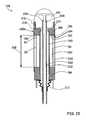
- FIG. 15is an enlarged sectional view of a second embodiment of the ablation head assembly of FIG. 11 ;
- FIG. 16is an enlarged sectional view of a third embodiment of the ablation head assembly of FIG. 11 ;
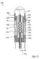
- FIG. 17is an enlarged sectional view of a fourth embodiment of the ablation head assembly of FIG. 11 ;
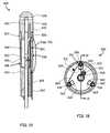
- FIG. 18is an enlarged end view of an ablation head assembly in an embodiment of the invention.
- FIG. 19is a cross-sectional view of the ablation head assembly of FIG. 18 ;
- FIGS. 20A through 20Dare expanded views of mounting arrangements of the strain sensor of FIG. 19 .
- a strain sensor assembly 20is depicted according to an embodiment of the invention.
- a proximal or base portion 22 and a distal or head portion 24are separated by a trio of strain sensing elements 26 .
- Each strain sensing element 26includes the standoff member 28 , a transmitting element 30 and a reflecting element 32 .
- Each standoff member 28is comprised of a hollow tube 34 having a proximal end 36 and a distal end 38 that are disposed in sockets 40 formed in the proximal and distal portions 22 and 24 .
- the transmitting element 30 of each strain sensing element 26includes a free end 44 that extends partway into the hollow tube 34 .
- the reflecting element 32includes an anchor end 46 and a free end 48 and is housed within the hollow tube 34 opposite the transmitting element 30 .
- the transmitting and reflecting elements 38 and 42are each secured to the hollow tube 36 with a potting 52 and are positioned to define a gap 54 between the free ends 44 and 48 .
- Each of the strain sensing elements 26are characterized by an active or strain sensing length 56 that is defined by the distance between the pottings 52 .
- the gap 54 and the free ends 44 and 48 of the transmitting and reflecting elements 30 and 32may cooperate to define an interferometric gap 60 having an operative length 61 .
- the operative length 61is the distance that establishes the characteristics of the interference pattern reflected back from the interferometric gap 60 . Accordingly, the free end 44 of the transmitting element 30 may be faced with a semi-reflecting surface 62 , and the free end 48 of the reflecting element 32 may be faced with a reflecting surface 64 .
- an “interferometric gap” as used hereinis a gap having the qualities of the cavity of an interferometer, such as found in a Michelson interferometer or a Fabry-Perot resonator.
- a “gap interferometer” as used hereinis an interferometer that utilizes an interferometric gap to produce an interference pattern.
- the proximal and distal ends 28 and 32may be press fit, glued or formed integrally with the respective proximal and distal portions 22 and 24 .
- the pottings 52may be comprised of a glue, epoxy or other adhesive compatible with the application and available to the artisan.
- FIG. 4an alternative embodiment of the strain sensor assembly 20 is depicted.
- the proximal and distal ends 36 and 38 of the standoff members 28are attached to the proximal and distal portions 22 and 24 of the strain sensor assembly 20 with potting 52 .
- the transmitting and reflecting elements 30 and 32are each connected to the hollow tube 34 with a fusion weld 66 .
- the separation between the fusion welds 66defines the active length 56 of the strain sensing element 26 in the embodiment of FIG. 4 .
- the hollow tube 34 , transmitting element 30 and reflecting element 32may be constructed of the same material, such as quartz.
- the proximal and distal portions 22 and 24may also be constructed from the same material, or of a material having a similar coefficient of thermal expansion (CTE).
- the potting 52may be chosen for a closely matching CTE.
- Hygroscopic materialsabsorb moisture and may tend to grow or swell when immersed in a liquid medium.
- the effect on the strain sensing elements 26differ from the effects of thermal expansion in that only those elements exposed to the liquid medium (i.e. the hollow tube 34 ) are potentially subject to dimensional change.
- the hollow tube 34which defines active length 56 , may undergo a dimensional change, whereas the transmitting and reflecting elements 30 and 32 contained therein and isolated from the moisture would not undergo a proportional dimensional change.
- the strain sensing system 70may comprise an electromagnetic source 72 , a coupler 74 , a receiver 76 , an operator console 77 operatively coupled with a microprocessor 78 and a storage device 79 .
- the electromagnetic source 72outputs a transmitted radiation 80 of electromagnetic radiation that is substantially steady state in nature, such as a laser or a broadband light source.
- a transmission line 82such as a fiber optic cable carries the transmitted radiation 80 to the coupler 74 , which directs the transmitted radiation 80 through a transmitting/receiving line 84 to the transmitting element 30 .
- a portion of the transmitted radiation 80enters the interferometric gap 60 within the strain sensing element 26 .
- the transmitting element 30 and transmitting/receiving line 84may be coupled through a connector 86 as depicted in FIG. 5 .
- the transmitting/receiving line 84may be operatively coupled with the interferometric gap 60 through a flexible, elongate catheter assembly 87 .
- the catheter assembly 87comprises a proximal portion 87 a , a middle portion 87 b and a distal portion 87 c .
- the distal portion 87 cmay include an end effector 88 that contains the interferometric gap 60 .
- the catheter assemblymay be of a hollow construction (i.e. having a lumen) or of a non-hollow construction (i.e. no lumen), depending on the application.
- a portion of the radiation that enters the interferometric gap 60is returned to transmitting element 30 as a modulated waveform 89 and is transmitted back through the transmitting/receiving line 84 to the receiver 76 .
- the strain sensing system 70may interrogate the interferometric gap 60 at an exemplary and non-limiting rate of 10-Hz.
- the receiver 76may be chosen from a variety of receiving devices available in the art, such as but not limited to that disclosed in U.S. Pat. Nos. 5,202,939 and 5,392,117 to Belleville, et al., disclosures of which are hereby incorporated by reference other than any express definitions of terms specifically defined therein.
- the receiver 76manipulates and/or converts the incoming modulated waveform 89 into digital signals for processing by the microprocessor 78 .
- the characteristics of the modulated waveform 89are determined in part by the dimension of the gap 54 .
- the strain sensor assembly 20is configured so that the gap 54 will vary when the strain sensing element 26 , or more specifically the standoff member 28 , experiences an axial strain. A change in the axial strain will cause a proportional change in the dimension of the gap 54 , thereby altering the characteristic of the modulated waveform 89 transmitted to the receiver 76 .
- the preceding embodimentsprovide a mechanical amplification of the growth of the gap 54 relative to the strain experienced by the strain sensing elements 26 .
- the gap 54is maintained by the locations where the transmitting and reflecting elements 30 and 32 is anchored to the standoff members 28 (i.e. pottings 52 or fusion welds 66 ). Accordingly, the gap 54 will be displaced by an accumulated change in the active length 56 due to axial loading (tension or compression).
- the construction of the strain sensing elements 26may be such that the active length 56 is several hundred times greater than the gap 54 , which provides substantial amplification of the gap 54 relative to its dimension.
- the preceding embodimentsmay also be relatively insensitive to bulk temperature changes of the strain sensor assembly 20 .
- L, ⁇ and ⁇ Tare, respectively, the CTE, length and the change in the bulk temperature, and the subscript “S” denotes the standoff member 28 .
- the accumulated change in the active length 56may dominate the change in the dimension of the gap 54 by a factor of several hundred times, making the assembly relatively insensitive to bulk temperature changes.
- the change in the active length 56 of the strain sensing element 26may be negligible when exposed to fluids.
- some or all of the components of the strain sensor assembly 20may be plated or coated with a material that serves as a barrier to moisture such as poly-para-xylylene (PARYLENE). Accordingly, the embodiments depicted in FIG. 1 and FIG. 4 may be made insensitive to moisture as well as bulk temperature change by proper selection of fabrication materials.
- a strain sensor assembly 90is presented as an alternative to the strain sensor assembly 20 wherein the transmitting and reflecting elements 30 , 32 are housed within in a single support tube 92 .
- the single support tube 92replaces the multiple hollow tubes 34 of FIGS. 1 through 4 and maintains the active length 56 of the strain sensor assembly 20 .
- the proximal and distal end portions 22 and 24are glued to the open ends of the single support tube 92 to form an enclosure.
- the support tube 92may be mounted in ring-shaped grooves formed on the interior faces of the proximal and distal end portions 22 , 24 (not depicted).
- a strain sensor assembly 94is depicted in another embodiment of the invention wherein the strain sensing elements 94 each comprise a standoff member 28 that is adjacent to rather than concentric with the transmitting and reflecting elements 30 and 32 .
- the standoff member 28may take the form of a straight, cylindrical rod 96 as depicted, or other shapes and cross sections.
- a thin tubular membrane 98may shroud the active length 56 of the strain sensor assembly 94 to encapsulate the sensing elements 26 in a common closure.
- the tubular membrane 98acts to keep body fluid from flooding the gap 54 and interfering with the operation of the interferometric gap 60 .
- the configuration and arrangement of the tubular membrane 98may be such that it does not exert a detectable force on the strain sensor assembly 94 when subject to thermal expansion or contraction.
- the tubular membrane 98may be of such a thin wall and of a compliant material so that it offers negligible resistance to compression, such as with a latex or rubber material.
- the tubular membrane 98may be mounted to the strain sensor assembly 94 with an excess length to enable the assembly to grow or contract and the gasses trapped within the annular gap 54 to expand or contract without exerting a tension force on the strain sensor assembly.
- the strain sensor assembly 94also reduces the potential deformation and attendant effect on the dimension of the gap 54 that may be caused by the expansion of trapped gas in the strain sensor elements 26 used in the strain sensor assembly 20 .
- the effects of trapped gas on a strain measurementmay be secondary or insignificant, and may not warrant attention.
- there may be applications where the expansion or contraction of trapped gas within a strain sensor assemblyis notable vis-à-vis the accuracy or resolution requirements of the application.
- the hollow tubes 34 of the sensor elements 26each represent a thin-walled cylindrical vessel with a large length-to-diameter or “aspect” ratio.
- the pressure of the gas entrapped within the sensor element 26will increase or decrease with temperature change, and may cause the profile of the hollow tube 34 to bulge or flex outward when the gas expands or inward when the gas contracts.
- the expansion or contractionmay also impose an axial strain on the hollow tube 34 .
- the combination of flexure of the wall and the axial strain of the hollow tube 34may cause the dimension of the gap 54 to change and cause the strains sensing system 70 to register a false change in the resolved force vector.
- strain sensor assembly 90 of FIGS. 6 and 7also include a volume of trapped gas that generally may cause deformation of the structure (i.e. single support tube 92 ) that maintains the gap 54 .
- the configuration of strain sensor assembly 90will also generally be more rigid and less sensitive to applied forces than the configuration of strain sensor assembly 20 .
- the strain sensor assembly 94reduces these deleterious effects because expansion of the trapped gas does act principally on the structure that also maintains the gap 54 . Rather, the pressure change will act primarily on the tubular membrane 98 , which is not a support element.
- the tubular membrane 98may be dimensioned to freely flex inward and outward, thereby greatly reducing the pressure change and the attendant axial strain imposed on the rod members 96 .
- the rod members 96may be sized to provide substantially less cross-sectional area and less stiffness than the single support tube 92 of strain sensor assembly 90 .
- a strain sensor assembly 100is depicted that includes a unibody structure 101 in an embodiment of the invention.
- the unibody structure 101includes a base portion 102 and a distal portion 104 separated by a stem portion 106 , all concentric about a central axis 108 .
- the base and distal portions 102 and 104may be characterized by a major radius 114 and the stem portion 106 by a minor radius 116 to define an annular gap 118 having a length 120 .
- the transmitting elements 30may be located on a sensing radius 117 and extend through the base portion 102 and across a majority of the length 120 to define a gap 124 between the free end 44 of the transmitting element 30 and an inward-facing surface 126 of the distal portion 104 .
- the annular gap 118surrounded a thin tubular membrane 122 to form a closure 123 .
- the free end 44 of the transmitting element 30may be configured as a semi-reflecting surface 62 .
- the inward surface 126or at least the portions immediately opposite free ends 44 of the transmitting elements 30 , may be made highly reflective to affect a Fabry-Perot resonator 130 across the gaps 124 .
- the fabrication of the Fabry-Perot resonator 130 in this wayeliminates the need for reflecting elements 32 .
- the tubular membrane 122may be of similar construction as discussed in connection with strain sensor assembly 94 to retain the same advantages.
- the unibody structure 101may be made from a material having a CTE similar to that of the transmitting elements 30 . Matching the CTEs of the structural element 101 and the transmitting elements 30 may be accomplished by fabricating the unibody structure 101 from the same material as the transmitting elements 30 .
- materials suitable for fiber optic applicationstend to be quite stiff, as measured by the modulus of elasticity or the so-called “Young's modulus.” Quartz, for example, has a Young's modulus of approximately 70 GPa. Compare this with, for example, structural polymers having a Young's modulus typically of 1 to 10 GPa. The result is that the unibody structure 101 as depicted that is fabricated from quartz is relatively stiff and will have a reduced sensitivity to applied forces relative in comparison with the strain sensor assemblies 20 , 90 and 94 .
- the unibody structure 101may be comprised of a material that closely matches the CTE of the transmitting elements 30 but possesses less stiffness.
- a materialthat closely matches the CTE of the transmitting elements 30 but possesses less stiffness.
- One such materialis liquid crystal polymer (LCP).
- LCPliquid crystal polymer
- the material properties of certain LCPsmay be found in “DUPONT ZENITE LCP liquid crystal polymer resin,” publication K-15415, May 2006, which is hereby incorporated by reference herein other than any express definitions of terms specifically defined therein.
- LCPsmay be fabricated for a CTE that is 5.0- ⁇ 10 ⁇ 6 per Kelvin (5.0- ⁇ /K) or less. A range of approximately 0.5- to 2.0- ⁇ /K is comparable with quartz. The Young's modulus, however, is on the order of 15 GPa, several factors lower than quartz.
- the extent to which the CTEs are matchedmay be dictated by the particular application.
- One application or designmay not require the same degree of accuracy in the determination of strain as another, or may not require operation over a broad range of temperatures.
- CTEs of the various componentsmay require closer matching if the strain sensor 20 is to operate over an operating range of 40° C. than an operating range of 5° C.
- one configurationmay have a higher mechanical amplification or gain than another which may allow for more tolerance in the matching of the various CTEs.
- the artisanmay use expressions such as detailed in Eqns. (1) through (6) above to establish a tolerable difference between the various CTEs and still provide a relatively consistent indication of contact force result over a range of temperatures.
- the unibody structure 101will generally deform or deflect more readily under a force load for the lower Young's modulus while maintaining a suitable insensitivity to bulk temperature changes because of the closely matched CTEs of the materials, as described above.
- An added benefit of utilizing the unibody structure 101 in the strain sensor assembly 100is the elimination of glued or bonded joints that are load bearing. Bonding joints may tend to undergo plastic deformation and/or molecular slippage at bonding interfaces when subjected to even moderate loads. Bonding materials having a substantially different CTE may also contribute to thermal expansion errors of the assembly. These characteristics may be manifested as a hysteresis or a bias error in the strain measurement.
- the unibody structure 101is free of bonded joints that experience a force load in operation. It is noted that the transmitting elements 30 may be bonded to the base portion 102 , but these bonds do not support a structural load due to application of a force vector on the distal portion 104 .
- the sensitivity of the strain sensor assembly 100may be further controlled by the sizing of the major and stem radii 114 , 116 .
- the deflection at the locations of the gaps 124 under a given force applied to the distal portion 104will generally increase as the stem radius 116 is decreased.
- the angular deflection (i.e. rotation about an axis that is orthogonal to the central axis 108 ) of the distal portion due to an eccentric force componentwill tend to be amplified as the ratio of the sensing radius 117 to the stem radius 116 is increased.
- an end effector 142that includes a strain sensor assembly 140 within an ablation head assembly 138 is portrayed in an embodiment of the invention.
- the particular end effector 142 portrayedincludes a radio-frequency (RF) ablator head 144 .
- RFradio-frequency
- Various appurtenancesmay be utilized in the operation of the end effector 142 .
- the RF ablator head 144such appurtenances may include an irrigation tube 146 in fluid communication with the RF ablator head 144 that effuses coolant through exit passages 148 .
- a plurality of transmitting elements 30extend into the strain sensor assembly 140 .
- the cathetermay comprise any of a number of end effectors, such as but not limited to RF ablation electrodes, rotary or scissor action cutting heads, laser ablation system, injection or sewing needles, fluid conveyance systems, forceps, manipulators, mapping electrodes, endoscopic vision systems and therapeutic delivery systems such as genetic impregnation devices.
- end effectorssuch as but not limited to RF ablation electrodes, rotary or scissor action cutting heads, laser ablation system, injection or sewing needles, fluid conveyance systems, forceps, manipulators, mapping electrodes, endoscopic vision systems and therapeutic delivery systems such as genetic impregnation devices.
- a force vector 150is depicted as being applied to the RF ablator head 144 , the force vector 150 being characterized by an orientation that presents an angle of application 152 between the force vector 150 and a central axis 154 of the ablation head assembly 138 .
- the force vector 150may be in reaction to the end effector 142 being brought into contact with an object such as the interior wall of a vessel or organ.
- the central axismay define the z-axis of an x-y-z coordinate system with origin at the distal extremity tip of the RF ablator head 144 .
- FIG. 13illustrates the ablation head assembly 138 as having a strain sensor assembly 140 a that includes a unibody structure 158 having a center bore 160 that accommodates the irrigation tube 146 .
- a distal portion 162 of the unibody structure 158includes a reflective surface 164 that cooperates with the free ends 44 of the transmitting element 30 to create a Fabry-Perot resonator 166 across a gap 167 .
- the unibody structure 158is wrapped with a thin membrane 168 to maintain keep the gaps 167 free of bodily fluids during operation.
- the unibody structure 158made of a material such as LCP to match the CTE of the transmitting elements 30 .
- the irrigation tube 146may also be made of a material that closely matches the CTE of the unibody structure 158 , such as the same material as the unibody structure 158 or the same material as the transmitting elements 30 .
- the RF ablator head 144includes an extension portion 170 for the irrigation passage.
- the extension portion 170cooperates with a socket or recess 172 on the distal portion 162 to create a joint that provides flow continuity between the center bore 160 and the RF ablator head 144 .
- a coolant 176is routed through the irrigation tube 146 .
- the coolant 176may have to run substantially cooler than the ambient working environment of the catheter in order adequately cool the RF ablator head 144 .
- a contraction of the irrigation tube 146may exert a compressive force on the unibody structure 158 that translates into a reduction in the dimension of the gaps 167 , thus casing an error in the apparent strain reading.
- FIG. 14also reduces the effects of differential thermal expansion.
- the center bore 160carries the coolant directly, thereby eliminating the need for and the potential CTE differential presented by the irrigation tube 146 .
- Non-limiting examples of the operating temperatures in a given applicationare 40 degrees Celsius (° C.) for the RF ablator head 144 , 26° C. for the coolant 176 and an ambient medium or working environment temperature of 37° C.
- the coolant 176is in close thermal coupling with the irrigation tube 146 and a stem portion 178 of the unibody structure 158 , causing the stem portion 178 to operate at a temperature close to that of the coolant 176 .
- the RF ablator head 144when operating at the higher temperature, conducts heat to the distal portion 162 of the unibody structure 158 .
- the temperature extremes of the systemare represented at the RF ablator head 144 and the irrigation tube 146 .
- the resulting increased temperature of the distal portion 162may cause it to expand and deform, particularly out at the sensing radius 117 which thermally is more closely coupled to the RF ablator head 144 than to the stem portion 178 .
- the transmitter elements 30extend from a base portion 180 of the unibody structure at the sensing radius 117 , which may be located closer to the major radius 114 than to the stem radius 116 to increase the force sensing resolution of the ablation head assembly 138 .
- the base portion 180 at the location of the sensing radius 117will be more closely thermally coupled to the ambient medium in which the ablation head assembly 138 is immersed. This introduces a third temperature that further contributes to thermal gradients.
- the transmitting elements 30are conductively coupled to this third temperature, and may experience a thermal expansion relative to the stem portion 178 .
- the combination of the cooler temperature of the stem portion 178 , the warmer temperature of the distal portion 162 and the intermittent temperature of the base portion 180may cause a change in the dimension of the gap 167 that translates to an apparent and false change in the strain.
- Thermal gradientscan be militated against by isolating the structural components that establish the dimension of the gap 167 from temperature extremes.
- An embodiment that utilizes this principleis presented in FIG. 15 .
- the ablation head assembly 138 depicted thereinutilizes a strain sensor assembly 140 b that includes a proximal portion 186 and distal portion 188 separated by a single tube standoff member 190 , with the free ends 44 of the transmitting elements 30 and an opposing face 192 of the distal portion 188 affecting a Fabry-Perot resonator 194 having a gap 196 .
- the strain sensor assembly 140 bcombines the single support tube concept of FIG. 6 with the reduced stem radius and the reflective face on the distal portion concepts of FIG. 10 .
- An active length 198is defined by the distance between opposing faces of the proximal and distal portions 186 and 188 , and is shrouded from the ambient medium with a tubular membrane 200 .
- An insulative annular gap 201is formed between the tubular membrane 200 and the single tube standoff member 190 .
- An irrigation tube 202may be aligned in substantial concentricity with the single tube standoff member 190 .
- the irrigation tube 190is supported at a distal end 204 within a socket 206 formed on a bottom face 208 of the RF ablator head 144 .
- the irrigation tube 190is held in substantial concentric alignment with the single tube standoff member 190 by a bellows member 210 that depends from the proximal portion 186 .
- a radial insulative gap 212is thereby defined in the form of an annulus between the exterior diameter of the irrigation tube 202 and the interior diameter of the single tube standoff member 190 .
- An axial insulative gap 214may also be provided between the bottom face 208 of the RF ablator head 144 and the distal portion 188 of the strain sensor assembly 140 b.
- the single tube standoff member 190may be fabricated from a variety of materials, as disclosed in the discussion attendant FIG. 6 .
- the bellows 210may be of a complaint material that offers little resistance to axial compression or extension.
- the various insulative gaps 201 , 212 and 214may contain any of a number of gases, including air or nitrogen, or gases known for their thermal resistance characteristics such as argon.
- the radial gap 212thermally isolates the irrigation tube 202 from the strain sensor assembly 140 b .
- thermal coupling between the irrigation tube 202 and strain sensor assembly 140 bis limited to conduction through the bellows member 210 and conduction and convection through the gas that fills the radial gap 212 .
- Heat transfer via conduction between the irrigation tube 202 and the RF ablator head 144contributes to the cooling of the RF ablator head 144 and essentially does not cool the strain sensor assembly 140 b .
- the axial gap 214serves to thermally isolate the RF ablator head 144 from the distal portion 188 , so that the conduction path is limited to a collar portion 216 that is formed on the distal portion 186 .
- the components that define the gap dimensioni.e. the distal and proximal portions 186 and 188 , the single tube standoff member 190 and the transmitting elements 30 ) are substantially thermally isolated from the extreme temperatures posed by the coolant 176 and the Joule-heated RF ablator head 144 .
- the ablation head assembly 138includes a strain sensor assembly 140 c that includes a unibody structure 222 having a collar portion 224 at a distal end 226 and a base portion 228 , the unibody structure 222 being in coaxial alignment with an irrigation tube 230 .
- the transmitting members 30form a plurality of Fabry Perot resonators 232 between the free ends 44 and a recessed reflective face 234 of the RF ablator head 144 .
- the recessed reflective face 234is axially offset with respect to a bottom face 236 of the RF ablator head 144 so that the recessed reflective face is at a datum 238 that is in common with a distal extremity 240 of the collar portion 224 .
- the base portion 228may include annular grooves 242 that define a flexure 244 .
- the coaxial arrangement between the strain sensor assembly 140 c and the irrigation tube 230defines an annular gap 246 .
- the location of the recessed reflective face 234 on the same datum 238 as the distal extremity 240 of the strain sensor assembly 140 csubstantially precludes movement of the recessed reflective face 234 relative to the distal extremity 240 .
- thermal expansion of the RF ablator head 144causes it to grow outward from the datum 238 , but does not change the position of the recessed reflective face 234 relative to the datum 238 .
- the dimension of the Fabry Perot resonatoris not affected by the differential thermal expansion between of the RF ablator head 144 and the unibody structure 222 .
- the flexure 244provides compliance that accommodates thermal expansion or contraction of the irrigation tube 230 that reduces the strain translated to the body of the unibody structure 222 .
- the flexure 244also reduces the conductive coupling between the irrigation tube 230 and the base portion 228 .
- the annular gap 246provides thermal isolation between the irrigation tube 230 and the unibody structure 222 , as well as between the irrigation tube 230 and the transmitting elements 30 .
- the unibody structure 222also encapsulates the transmitting elements 30 , eliminating the need for a tubular membrane.
- FIG. 17depicts another embodiment of the present invention.
- the ablation head assembly 138comprises a strain sensor assembly 140 d having a unibody structure 252 with a distal portion 254 , a stem portion 256 and a base portion 258 .
- the base and distal portions 258 and 254are characterized by a major radius 260 , and the stem portion by a stem radius 262 that is less than the major radius 260 .
- the difference in radii 260 and 262creates an annular gap 264 .
- the transmitting elements 230extend into the annular gap 264 , with the free ends 44 and a reflective bottom surface 266 of the distal portion 254 to create a plurality of Fabry-Perot resonators 268 .
- a tubular membrane 270encapsulates the annular gap 264 .
- An irrigation tube 272is concentric with the strain sensor assembly 140 d .
- the irrigation tube 272includes a bellows portion 274 that extends at least partially between the RF ablator head 144 and the base portion 258 of the unibody structure 252 .
- a radial gap 276is defined between the bellows portion 274 and the stem portion 256 of the strain sensor assembly 140 d.
- a distinction of the strain sensor assembly 140 d embodimentis the bellows portion 274 of the irrigation tube 272 .
- the bellows portion 274may be designed for substantial radial stiffness through the use of radially-oriented fibers or cords, while remaining compliant in the axial direction.
- the axial compliancemitigates against inducement of strain in the unibody structure 252 as the bellows portion 274 expands and contracts. Otherwise, the function of the various gaps depicted in FIG. 17 provide thermal isolation between the irrigation tube 272 , RF ablator head 144 and the unibody structure 252 .
- the tubular membrane 270provides relief due to thermal expansion and contraction of the gas entrapped in the annular gap 264 , as discussed in connection with FIG. 8 .
- an embodiment of a ablation head assembly 300including a strain sensor assembly 302 and a radio-frequency (RF) ablator head 306 .
- the ablation head assembly 300may include numerous appurtenances for effective operation, including but not limited to an irrigation tube 308 , an RF cable 310 and a temperature sensor 312 for monitoring the temperature of the RF ablator head 306 .
- the strain sensor assembly 302includes a unibody structure 318 having a collar portion 320 , a stem portion 322 and a base portion 324 .
- the RF ablator head 306is secured within the collar portion 320 , and includes a central bore 326 in fluid communication with exit passages 328 that may provide for cooling of the RF ablator head 306 both internally and by film cooling of the exterior.
- a thermocouple port 330may be formed in the RF ablator head 306 .
- the RF cable 310may be routed through an access port 332 adjacent the irrigation tube 308 .
- the strain sensor assembly 302may utilize a plurality of strain sensors 336 that may be of a coaxial construction and may include a transmitting element 338 and a reflecting element 340 , each attached to an outer tubular portion 342 at contact locations 344 and 346 .
- a Fabry-Perot resonator 347 having an operative length 349is defined between the free ends of the transmitting and reflecting elements 338 and 340 .
- the strain sensors 336may be further characterized by a proximal end 348 and a distal end 350 .
- the strain sensors 336may be bonded directly to the unibody structure 318 across a continuous length of the strain sensor 336 .
- One bonding techniquemay involve the use of a solvent designed to cause the material of the unibody structure 318 to melt or flow while not affecting the material of the strain sensor 336 .
- the solventmay be applied to an area or zone 351 of the unibody structure 318 where the strain sensors 336 are to be mounted, and the strain sensor 336 placed thereon.
- the strain sensors 336may be temporarily held in place on the zone 351 of the unibody structure 318 and the solvent applied to both.
- the flowing of the material in the zone 351causes a bond between the unibody structure 318 and the outer tubular portion 342 of the strain sensor 336 .
- the solventmay be removed by a process such as washing or evaporation to arrest the melting process.
- the use of the solventmay also be incorporated with separate or non-unibody structures, such as depicted in FIG. 1 through 9 , to mount standoff members 28 or 190 .
- FIG. 20Ban embodiment of the invention wherein the strain sensors 336 are bonded to the unibody structure 318 using a bonding agent 355 such as glue or epoxy is depicted.
- the bonding agent 355may be selected for closest available CTE, or for flexibility so that the thermal growth of the adhesive film does not impose a substantial strain on the strain sensor 336 .
- Use of a very thin film of bonding agent 355may also mitigate the effects of differential thermal expansion.
- each strain sensor 336may be mounted to the unibody structure 318 at two locations: a proximal location 352 near the proximal end 348 and a distal location 354 near the distal end 350 .
- the bonding agent 355is discontinuous along a span distance 356 .
- An active length of the strain sensor 336may be defined by a span distance 356 between the proximal and distal locations 352 and 354 , or by a separation distance 358 between contact locations 344 and 346 , whichever is less. Accordingly, the active length for the configuration of FIG. 20C is generally the span distance 356 , whereas the active length of the configuration of FIG. 20D is generally the separation distance 358 .
- the CTE of the bonding agent 355may be substantially dissimilar without introducing unacceptable error to the strain measurement.
- the unibody structure 318may be formed with grooves 360 that enable the strain sensing elements 336 to be mounted thereto without increasing the radial profile of the ablation head assembly 300 .
- Each strain sensing element 336has a fiber optic lead cable 362 that is in communication with the strain sensing elements 336 .
- the fiber optic lead cables 362may be routed through slots 364 formed in the base portion 324 .
- the stem portion 322has an inner diameter 366 that is larger than the outer diameter of the irrigation tube 308 , thus providing an annulus 368 .
- the irrigation tube 308is fabricated from a thin-walled, compliant tubing material that imposes a small or negligible strain on the unibody structure 318 when undergoing expansion or contraction.
- Representative and non-limiting dimensions for the ablation head assembly 300include an overall length of approximately 15- to 20-mm, an outer diameter of 2.3- to 2.6-mm (7 to 8 French) and a length of the strain sensor 336 of approximately 5- to 10-mm.
- the irrigation tube 308may be a thin, tubular membrane having a wall thickness on the order of 10- to 20-micrometers ( ⁇ m).
- an exemplary and non-limiting dimension for the clearance between the irrigation tube 308 and the inner diameter 366 of the stem portion 322is 200- to 300- ⁇ m.
- Exemplary operative lengths 349may range from 10- to 50- ⁇ m.
- strain that is experienced by the unibody structure 318is translated to the outer tubing portion 342 of the strain sensor 336 via the bonding agents 355 at the proximal and distal locations 352 and 354 .
- the strain experienced by the outer tubing portion 342causes the transmitting and reflecting elements 338 and 340 to translate along the central axis of the strain sensor 336 , thereby altering the dimension of the Fabry-Perot resonator 347 .
- the magnitude of the translationis the same as the magnitude of the relative movement between contact locations 344 and 346 . For configurations where the distance 358 between contact locations 344 and 346 is less than the span distance 356 between the proximal and distal locations 352 and 354 , such as depicted in FIG.
- the annulus 368separates the irrigation tube 308 from the stem portion 322 , providing some of the thermal isolation advantages and effects previously discussed.
- An elastic strain ⁇ corresponding to a given change in the operative length of an interferometric gapmay be determined with commercially available instruments, such as the FTI-10 Single-Channel Signal Conditioner marketed by FISO Technologies, Inc. of Quebec, Canada.
- the elastic strains ⁇are related to the internal forces experienced by the standoff member(s) as a function of the physical dimensions and the material properties of the deformable body.
- Equation (7)may be rearranged to solve for the internal forces as a function of the elastic strain:
- the internal forces experienced by the optical fiber sensorsare computed based on the positions of the optical fiber sensors from the exterior wall of the deformable body, assuming the deformable body is substantially incompressible:
- Equations (7) through (9)are related to the material properties of the deformable body or optical fiber sensors, such as the elastic moduli of the deformable body.
- Other valuessuch as the coordinate distances between the optical fiber sensors, the operative lengths of the interferometric gaps and the external surface of the deformable body may be subject to variations as a consequence manufacturing tolerances.
- storage device 79may comprise a memory chip associated with the transmitting/receiving line 84 in which such information is stored, or a bar code or a RFID tag located on the body of the strain sensor assembly 20 or on the packaging.
- data specific to an individual deformable bodymay be uploaded to console 77 from an item of removable storage (e.g., CD) or via secure download from the manufacturer's website.
- the information specific to each deformable bodymay be obtained during a calibration step, conducted during manufacture of the deformable body, by subjecting the deformable body to a series of known forces.
- ⁇ (t)is the vector of strains [ ⁇ 1,t , ⁇ 2,t , ⁇ 3,t ] of the interference pattern measured for the individual sensors
- ⁇ 0is the vector of strains [ ⁇ 0 1 , ⁇ 0 2 , ⁇ 0 3 ] measured for the individual sensors with zero applied force
- Kis a matrix computed when the deformable body is subjected to the series of known forces
- the deformable bodyis subjected to the following forces in series: (1) a purely axial force of known magnitude F z,t ; (2) a lateral force of known magnitude F x,t ; and (3) a lateral force of known magnitude F y,t applied 90 degrees to the orientation of force F x,t .
- the force-to-strain conversion matrix Kmay be computed as:
- Force-to-strain conversion matrix Kthen may be stored in storage device 79 associated with the corresponding deformable body, as disclosed herein.
- the values of the force-to-conversion matrixthen may be input to console 77 when the deformable body is coupled to the console using a bar code reader, input pad or direct electrical connection through transmitting/receiving line 84 .
- matrix KOnce matrix K is provided for a given deformable body, the normal force, transverse force and angle of application of the transverse force may be computed as described above and using Table I.
- the values for the normal force, transverse force and angle of application of the transverse force, computed as described above,may be output as numerical values to a display monitor that forms part of console 77 .
- a graphic including a variable size or colored arrowmay be displayed pointing at a position on the circumference of a circle to visualize the magnitude and direction of the transverse force applied to the distal extremity of the deformable body. By monitoring this display, the operator may continuously obtain feedback concerning the contact forces applied to the distal extremity of the deformable body.
- the inventionmay be practiced in other embodiments not disclosed herein, such as endoscopic or additional intravascular applications.
- various aspects of the disclosed embodimentsmay be utilized in a diagnostic catheter for optimizing or otherwise improving the placement of excitation electrodes for baroreflex activation.
- Other aspects of the disclosed embodimentsmay find application in endoscopic applications, such as orthoscopic surgery or entry through open orifices such as the throat, nose or anus without departing from the spirit of the invention.
Landscapes
- Health & Medical Sciences (AREA)
- Life Sciences & Earth Sciences (AREA)
- Surgery (AREA)
- Engineering & Computer Science (AREA)
- General Health & Medical Sciences (AREA)
- Veterinary Medicine (AREA)
- Biomedical Technology (AREA)
- Heart & Thoracic Surgery (AREA)
- Medical Informatics (AREA)
- Molecular Biology (AREA)
- Public Health (AREA)
- Animal Behavior & Ethology (AREA)
- Pathology (AREA)
- Biophysics (AREA)
- Physics & Mathematics (AREA)
- Nuclear Medicine, Radiotherapy & Molecular Imaging (AREA)
- Oral & Maxillofacial Surgery (AREA)
- Media Introduction/Drainage Providing Device (AREA)
- Length Measuring Devices By Optical Means (AREA)
- Endoscopes (AREA)
Abstract
Description
ΔLS=[α·L·ΔT]S Eqn. (1)
where L, α and ΔT are, respectively, the CTE, length and the change in the bulk temperature, and the subscript “S” denotes the
ΔLT=[α·L·ΔT]T Eqn. (2)
ΔLR=[α·L·ΔT]R Eqn. (3)
where the subscripts “T” and “R” denote, respectively, the transmitting
lG=LS−(LT+LR) Eqn. (4)
where lGis the operative length61 of the
ΔlG=ΔLS−(ΔLT+ΔLR)=[α·L·ΔT]S−([α·L·ΔT]T+[α·L·ΔT]R) Eqn. (5)
ΔlG=α·ΔT·[LS−(LT+LR)]=α·ΔT·lG Eqn. (6)
- Where:
- xiand yi, i=1, 3—coordinates of gap interferometer with respect to center of gravity of the catheter cross-section
- εelij, i=1, 3—elastic strain values at time t
- Eten—Equivalent tension/compression Young modulus of catheter
- Eflex—Equivalent flexural Young modulus of catheter
- Ix—Moment of inertia with respect to x axis
- Iy—Moment of inertia with respect to y axis
- Nz,t—Normal force in direction of z axis at time t
- Mx,t—Bending moment with respect to x axis at time t
- My,t—Bending moment with respect to y axis at time t
- G—Geometry matrix
- δ—Matrix of flexibility
- IF,t—Matrix (vector) of internal forces at time t
- Where:
- Where: S=δ−1—Stiffness matrix
- Where:
- Fx,t—Touching external transversal force at time t, in direction of x axis (with opposite sense)
- Fy,t—Touching external transversal force at time t, in direction of y axis (with opposite sense)
- Fz,t—Touching external normal force at time t in direction of z axis (with opposite sense, compression is positive)
- d—distance between the touching point of lateral forces and the cross-section with sensors (along z axis)
- Ft—Matrix of touching external forces at time t
- d—Matrix of conversion
- Where:
| TABLE I | ||||
| Fx,t | Fy,t | γt | ||
| ≧0 | ≧0 | arcsin(Fy,t/Ftran,t) | ||
| <0 | ≧0 | Π − arcsin(Fy,t/Ftran,t) | ||
| <0 | <0 | Π + arcsin(Fy,t/Ftran,t) | ||
| ≧0 | <0 | 2 * Π − arcsin(Fy,t/Ftran,t) | ||
F(t)=K(ε(t)−ε0) Eqn. (11)
where F(t) is the vector of forces [Fx,,t, Fy,,t, Fz,,t] (corresponding for example to the
Force-to-strain conversion matrix K then may be stored in
Claims (31)
Priority Applications (4)
| Application Number | Priority Date | Filing Date | Title |
|---|---|---|---|
| US11/753,429US8157789B2 (en) | 2007-05-24 | 2007-05-24 | Touch sensing catheter |
| EP08826173.0AEP2157930B1 (en) | 2007-05-24 | 2008-05-23 | Touch sensing catheter |
| PCT/IB2008/002675WO2009007857A2 (en) | 2007-05-24 | 2008-05-23 | Touch sensing catheter |
| EP19169343.1AEP3560416B1 (en) | 2007-05-24 | 2008-05-23 | Touch sensing catheter |
Applications Claiming Priority (1)
| Application Number | Priority Date | Filing Date | Title |
|---|---|---|---|
| US11/753,429US8157789B2 (en) | 2007-05-24 | 2007-05-24 | Touch sensing catheter |
Publications (2)
| Publication Number | Publication Date |
|---|---|
| US20080294144A1 US20080294144A1 (en) | 2008-11-27 |
| US8157789B2true US8157789B2 (en) | 2012-04-17 |
Family
ID=40073098
Family Applications (1)
| Application Number | Title | Priority Date | Filing Date |
|---|---|---|---|
| US11/753,429ActiveUS8157789B2 (en) | 2007-05-24 | 2007-05-24 | Touch sensing catheter |
Country Status (3)
| Country | Link |
|---|---|
| US (1) | US8157789B2 (en) |
| EP (2) | EP2157930B1 (en) |
| WO (1) | WO2009007857A2 (en) |
Cited By (22)
| Publication number | Priority date | Publication date | Assignee | Title |
|---|---|---|---|---|
| US20090177095A1 (en)* | 2006-06-09 | 2009-07-09 | Nicolas Aeby | Triaxial fiber optic force sensing catheter |
| US20110019893A1 (en)* | 2009-07-22 | 2011-01-27 | Norbert Rahn | Method and Device for Controlling the Ablation Energy for Performing an Electrophysiological Catheter Application |
| US20110087112A1 (en)* | 2005-08-01 | 2011-04-14 | Giovanni Leo | Medical apparatus system having optical fiber load sensing |
| US20110107852A1 (en)* | 2009-11-06 | 2011-05-12 | Baker Hughes Incorporated | Temperature insensitive devices and methods for making same |
| US20110263934A1 (en)* | 2006-06-09 | 2011-10-27 | Endosense Sa | Catheter having tri-axial force sensor |
| US20110319910A1 (en)* | 2007-08-14 | 2011-12-29 | Hansen Medical, Inc. | Methods and devices for controlling a shapeable instrument |
| WO2012142588A1 (en) | 2011-04-14 | 2012-10-18 | Endosense S.A. | Compact force sensor for catheters |
| US20130331650A1 (en)* | 2005-03-30 | 2013-12-12 | Intuitive Surgical, Inc. | Optic Fiber Connection for a Force Sensing Instrument |
| US8622935B1 (en) | 2007-05-25 | 2014-01-07 | Endosense Sa | Elongated surgical manipulator with body position and distal force sensing |
| WO2014184665A2 (en) | 2013-04-30 | 2014-11-20 | St. Jude Medical Luxembourg Holding Sarl | Control handles for catheters |
| US8932288B2 (en) | 2005-03-04 | 2015-01-13 | Endosense Sa | Medical apparatus system having optical fiber load sensing capability |
| US20170143441A1 (en)* | 2009-08-21 | 2017-05-25 | St. Jude Medical, Cardiology Division, Inc. | Flexible sensors and related systems for determining forces applied to an object, such as a surgical instrument, and methods for manufacturing same |
| US20170296779A1 (en)* | 2009-10-07 | 2017-10-19 | Endophys Holdings, Llc | Devices and systems for use in bodily lumens |
| US10219702B2 (en) | 2014-03-26 | 2019-03-05 | St. Jude Medical, Cardiology Division, Inc. | Single fiber force-sensing of both axial and bending catheter tip forces |
| US10350423B2 (en) | 2016-02-04 | 2019-07-16 | Cardiac Pacemakers, Inc. | Delivery system with force sensor for leadless cardiac device |
| US10507056B2 (en) | 2015-10-01 | 2019-12-17 | General Electric Company | System and method for representation and visualization of catheter applied force and power |
| US10564057B2 (en) | 2015-03-23 | 2020-02-18 | Farrokh Janabi-Sharifi | Temperature invariant force and torque sensor assemblies |
| US10716921B2 (en) | 2001-07-13 | 2020-07-21 | Endophys Holdings, Llc | Methods of using a dual-lumen sheath in intraluminal procedures |
| US20210186648A1 (en)* | 2017-10-10 | 2021-06-24 | Yan Xia | Surgical shape sensing fiber optic apparatus and method thereof |
| US11445937B2 (en) | 2016-01-07 | 2022-09-20 | St. Jude Medical International Holding S.À R.L. | Medical device with multi-core fiber for optical sensing |
| US11975157B2 (en) | 2019-04-12 | 2024-05-07 | Covidien Lp | Method of manufacturing an elongated catheter having multiple sensors for three-dimensional location of the catheter |
| US12303290B2 (en) | 2020-01-27 | 2025-05-20 | Howmedica Osteonics Corp. | Medical sensor and method |
Families Citing this family (86)
| Publication number | Priority date | Publication date | Assignee | Title |
|---|---|---|---|---|
| US8182433B2 (en) | 2005-03-04 | 2012-05-22 | Endosense Sa | Medical apparatus system having optical fiber load sensing capability |
| US8496647B2 (en) | 2007-12-18 | 2013-07-30 | Intuitive Surgical Operations, Inc. | Ribbed force sensor |
| US7625014B2 (en)* | 2006-09-26 | 2009-12-01 | Alcon, Inc. | Dual fluid connector |
| US9855410B2 (en) | 2007-05-01 | 2018-01-02 | St. Jude Medical, Atrial Fibrillation Division, Inc. | Optic-based contact sensing assembly and system |
| US8577447B2 (en) | 2007-05-01 | 2013-11-05 | St. Jude Medical, Atrial Fibrillation Division, Inc. | Optic-based contact sensing assembly and system |
| US8347738B2 (en)* | 2007-05-09 | 2013-01-08 | The Board Of Trustees Of The Leland Stanford Junior University | Sensors and control for an interventional catheter |
| US8157789B2 (en) | 2007-05-24 | 2012-04-17 | Endosense Sa | Touch sensing catheter |
| US8357152B2 (en) | 2007-10-08 | 2013-01-22 | Biosense Webster (Israel), Ltd. | Catheter with pressure sensing |
| US8535308B2 (en) | 2007-10-08 | 2013-09-17 | Biosense Webster (Israel), Ltd. | High-sensitivity pressure-sensing probe |
| US8561473B2 (en) | 2007-12-18 | 2013-10-22 | Intuitive Surgical Operations, Inc. | Force sensor temperature compensation |
| JP5397965B2 (en)* | 2008-03-19 | 2014-01-22 | センソプティック エスエイ | Optical measuring element with unitary structure |
| US8298227B2 (en) | 2008-05-14 | 2012-10-30 | Endosense Sa | Temperature compensated strain sensing catheter |
| US8437832B2 (en) | 2008-06-06 | 2013-05-07 | Biosense Webster, Inc. | Catheter with bendable tip |
| US7720322B2 (en)* | 2008-06-30 | 2010-05-18 | Intuitive Surgical, Inc. | Fiber optic shape sensor |
| US9101734B2 (en) | 2008-09-09 | 2015-08-11 | Biosense Webster, Inc. | Force-sensing catheter with bonded center strut |
| US9326700B2 (en) | 2008-12-23 | 2016-05-03 | Biosense Webster (Israel) Ltd. | Catheter display showing tip angle and pressure |
| US8600472B2 (en) | 2008-12-30 | 2013-12-03 | Biosense Webster (Israel), Ltd. | Dual-purpose lasso catheter with irrigation using circumferentially arranged ring bump electrodes |
| US8475450B2 (en) | 2008-12-30 | 2013-07-02 | Biosense Webster, Inc. | Dual-purpose lasso catheter with irrigation |
| EP2381998B1 (en)* | 2008-12-31 | 2018-04-25 | St. Jude Medical, Atrial Fibrillation Division, Inc. | Optic-based contact sensing assembly and system |
| US8491574B2 (en)* | 2009-03-30 | 2013-07-23 | Intuitive Surgical Operations, Inc. | Polarization and temperature insensitive surgical instrument force transducer |
| US9393068B1 (en) | 2009-05-08 | 2016-07-19 | St. Jude Medical International Holding S.À R.L. | Method for predicting the probability of steam pop in RF ablation therapy |
| CA2703347C (en) | 2009-05-08 | 2016-10-04 | Endosense Sa | Method and apparatus for controlling lesion size in catheter-based ablation treatment |
| US8195013B2 (en)* | 2009-08-19 | 2012-06-05 | The United States Of America, As Represented By The Secretary Of The Navy | Miniature fiber optic temperature sensors |
| US10688278B2 (en) | 2009-11-30 | 2020-06-23 | Biosense Webster (Israel), Ltd. | Catheter with pressure measuring tip |
| US8920415B2 (en) | 2009-12-16 | 2014-12-30 | Biosense Webster (Israel) Ltd. | Catheter with helical electrode |
| US8521462B2 (en) | 2009-12-23 | 2013-08-27 | Biosense Webster (Israel), Ltd. | Calibration system for a pressure-sensitive catheter |
| AU2015202549B2 (en)* | 2009-12-28 | 2017-03-02 | Biosense Webster (Israel), Ltd. | Catheter with strain gauge sensor |
| US8529476B2 (en)* | 2009-12-28 | 2013-09-10 | Biosense Webster (Israel), Ltd. | Catheter with strain gauge sensor |
| US8641708B2 (en)* | 2009-12-29 | 2014-02-04 | Biosense Webster (Israel), Ltd. | Measuring weak signals over ablation lines |
| US8608735B2 (en) | 2009-12-30 | 2013-12-17 | Biosense Webster (Israel) Ltd. | Catheter with arcuate end section |
| US8374670B2 (en) | 2010-01-22 | 2013-02-12 | Biosense Webster, Inc. | Catheter having a force sensing distal tip |
| US8906013B2 (en) | 2010-04-09 | 2014-12-09 | Endosense Sa | Control handle for a contact force ablation catheter |
| US9179968B2 (en) | 2010-05-10 | 2015-11-10 | St. Jude Medical Luxembourg Holding S.À.R.L. | Irrigated finned ablation head |
| US8798952B2 (en) | 2010-06-10 | 2014-08-05 | Biosense Webster (Israel) Ltd. | Weight-based calibration system for a pressure sensitive catheter |
| US8226580B2 (en) | 2010-06-30 | 2012-07-24 | Biosense Webster (Israel), Ltd. | Pressure sensing for a multi-arm catheter |
| KR101841067B1 (en) | 2010-07-20 | 2018-03-22 | 더 존스 홉킨스 유니버시티 | Interferometric force sensor for surgical instruments |
| US8380276B2 (en) | 2010-08-16 | 2013-02-19 | Biosense Webster, Inc. | Catheter with thin film pressure sensing distal tip |
| US8731859B2 (en) | 2010-10-07 | 2014-05-20 | Biosense Webster (Israel) Ltd. | Calibration system for a force-sensing catheter |
| US20130220032A1 (en) | 2010-10-26 | 2013-08-29 | Muthukumaran Packirisamy | System For Sensing a Mechanical Property of a Sample |
| US8979772B2 (en) | 2010-11-03 | 2015-03-17 | Biosense Webster (Israel), Ltd. | Zero-drift detection and correction in contact force measurements |
| EP3482708B1 (en) | 2010-12-27 | 2021-03-10 | St. Jude Medical International Holding S.à r.l. | Prediction of atrial wall electrical reconnection based on contact force measured duing rf ablation |
| US9149327B2 (en) | 2010-12-27 | 2015-10-06 | St. Jude Medical Luxembourg Holding S.À.R.L. | Prediction of atrial wall electrical reconnection based on contact force measured during RF ablation |
| EP2491883B1 (en) | 2011-02-24 | 2014-06-18 | VascoMed GmbH | Catheter and catheter arrangement |
| US9220433B2 (en) | 2011-06-30 | 2015-12-29 | Biosense Webster (Israel), Ltd. | Catheter with variable arcuate distal section |
| US9662169B2 (en) | 2011-07-30 | 2017-05-30 | Biosense Webster (Israel) Ltd. | Catheter with flow balancing valve |
| EP2586363A1 (en) | 2011-10-24 | 2013-05-01 | VascoMed GmbH | Catheter and catheter system |
| US9039700B2 (en)* | 2011-12-29 | 2015-05-26 | St. Jude Medical, Atrial Fibrillation Division, Inc. | Irrigated ablation catheter with contact force sensing mechanism |
| US9687289B2 (en) | 2012-01-04 | 2017-06-27 | Biosense Webster (Israel) Ltd. | Contact assessment based on phase measurement |
| EP2617453A1 (en) | 2012-01-19 | 2013-07-24 | VascoMed GmbH | Catheter and catheter arrangement |
| CN103239241A (en)* | 2012-02-07 | 2013-08-14 | 森斯奥普蒂克股份公司 | Optical force measuring element and microsurgical device |
| EP2626680B1 (en)* | 2012-02-07 | 2015-10-07 | Sensoptic SA | Optical force sensing element and microsurgical instrument |
| US9050105B2 (en) | 2012-03-20 | 2015-06-09 | Biosense Webster (Israel) Ltd. | Catheter with multiple irrigated electrodes and a force sensor |
| US9539056B2 (en) | 2012-03-20 | 2017-01-10 | Biosense Webster (Israel) Ltd. | Catheter with multiple irrigated electrodes and a force sensor |
| US10022190B2 (en) | 2012-04-04 | 2018-07-17 | Universite Libre De Bruxelles | Optical force transducer |
| EP2711676B1 (en) | 2012-09-20 | 2020-10-07 | VascoMed GmbH | Fiber-optic force sensor, force measurement device and catheter |
| US9174024B1 (en) | 2013-03-15 | 2015-11-03 | St. Jude Medical Luxembourg Holdings S.À.R.L. | Steering control mechanisms for catheters |
| EP2851028A1 (en) | 2013-08-15 | 2015-03-25 | VascoMed GmbH | Catheter arrangement and method for determining a force applied to a catheter end |
| DE102013111817A1 (en) | 2013-10-25 | 2015-04-30 | Raoul Hecker | Pressure measuring device |
| US10299826B2 (en)* | 2013-12-18 | 2019-05-28 | Sensoptic Sa | Needle for invasive medical use and needle assembly |
| US20170215970A1 (en) | 2014-05-01 | 2017-08-03 | St. Jude Medical, Cardiology Division, Inc. | Depicting force |
| USD761313S1 (en) | 2014-05-01 | 2016-07-12 | St. Jude Medical, Cardiology Division, Inc. | Display screen with a transitional graphical user interface |
| USD761808S1 (en) | 2014-05-01 | 2016-07-19 | St. Jude Medical, Cardiology Division, Inc. | Display screen with transitional graphical user interface |
| US9955917B2 (en) | 2014-06-11 | 2018-05-01 | Vascomed Gmbh | Planar logic board for ablation catheter with force measurement functionality |
| CN105232141B (en)* | 2015-09-30 | 2018-03-13 | 乐普(北京)医疗器械股份有限公司 | A kind of medical catheter head end for surveying contact force |
| CN105343984A (en)* | 2015-10-14 | 2016-02-24 | 乐普(北京)医疗器械股份有限公司 | Guide wire |
| CN106859762B (en)* | 2015-12-11 | 2020-01-24 | 上海微创电生理医疗科技有限公司 | Electrophysiology catheter |
| CN113425344A (en)* | 2016-06-30 | 2021-09-24 | 直观外科手术操作公司 | System and method for fault reaction mechanism for medical robotic system |
| CN110063788B (en)* | 2016-07-29 | 2021-04-30 | 上海微创电生理医疗科技股份有限公司 | Pressure sensor and electrophysiology catheter |
| EP4327732A3 (en) | 2017-01-12 | 2024-04-24 | The Regents of The University of California | Endovascular perfusion augmentation for critical care |
| US20180242886A1 (en)* | 2017-02-28 | 2018-08-30 | St. Jude Medical International Holding S.À R.L. | Elastomeric moisture barrier for force sensor |
| CA3060519A1 (en) | 2017-04-21 | 2018-10-25 | The Regents Of The University Of California | Aortic flow meter and pump for partial-aortic occlusion |
| KR102030237B1 (en)* | 2017-08-02 | 2019-10-08 | 재단법인 아산사회복지재단 | Catheter using the optical fiber for force sensing and catheter system thereby |
| US12161393B2 (en)* | 2018-03-13 | 2024-12-10 | St. Jude Medical International Holding S.á r.l. | Force sensing catheter system |
| EP4218643B1 (en)* | 2018-06-08 | 2025-07-16 | St. Jude Medical International Holding S.à r.l. | One fiber force and shape sensing |
| US20210228272A1 (en)* | 2018-08-07 | 2021-07-29 | St. Jude Medical International Holding S.À R.L. | Fluid gel for fiber optic gap |
| US11181406B2 (en) | 2019-12-03 | 2021-11-23 | Woodward, Inc. | Ultrasonic mass fuel flow meter |
| USD950598S1 (en) | 2020-03-13 | 2022-05-03 | Aristocrat Technologies, Inc. (ATI) | Display screen or portion thereof with transitional graphical user interface |
| EP4121159A2 (en) | 2020-03-16 | 2023-01-25 | Certus Critical Care, Inc. | Blood flow control devices, systems, and methods and error detection thereof |
| US20230165655A1 (en)* | 2020-04-08 | 2023-06-01 | Incite Medical Sarl | Catheter distal force sensor |
| CN113855215B (en)* | 2020-06-30 | 2025-07-18 | 上海微创电生理医疗科技股份有限公司 | Medical catheter |
| EP4193127A1 (en) | 2020-08-07 | 2023-06-14 | Woodward, Inc. | Ultrasonic flow meter flow control |
| US12140669B2 (en)* | 2020-08-07 | 2024-11-12 | Woodward, Inc. | Ratio metric position sensor and control system |
| US11668818B2 (en)* | 2020-08-07 | 2023-06-06 | Woodward, Inc. | Ultrasonic position sensor |
| US11835374B2 (en) | 2021-03-17 | 2023-12-05 | Woodward, Inc. | Ultrasonic mass fuel flow meter |
| WO2023086344A1 (en)* | 2021-11-09 | 2023-05-19 | Certus Critical Care, Inc. | Systems, devices, and methods for monitoring physiologic conditions during a medical procedure |
| WO2025152925A1 (en)* | 2024-01-15 | 2025-07-24 | 北京佰为深科技发展有限公司 | Force sensor, force sensing catheter, ablation device and medical apparatus |
Citations (143)
| Publication number | Priority date | Publication date | Assignee | Title |
|---|---|---|---|---|
| DE3020785A1 (en) | 1980-05-31 | 1981-12-10 | Erich 7993 Kressbronn Brosa | Measurement transducer for insertion in narrow tubular bodies - contains shearing force strain gauges located at points of weakness |
| US4757194A (en) | 1986-10-10 | 1988-07-12 | Oxbridge, Inc. | Methods and apparatus for sensing the mechanical application of force |
| EP0281405A3 (en) | 1987-03-06 | 1988-11-09 | THE UNITED STATES OF AMERICA as represented by the Secretary United States Department of Commerce | Oxyhydrogen catalytic thermal tip for angioplasty and the like |
| US4873989A (en) | 1984-03-08 | 1989-10-17 | Optical Technologies, Inc. | Fluid flow sensing apparatus for in vivo and industrial applications employing novel optical fiber pressure sensors |
| DE3828550A1 (en) | 1988-08-23 | 1990-03-01 | Rheinmetall Gmbh | Force measuring ring |
| US4918492A (en) | 1987-03-24 | 1990-04-17 | Electricite De France - Service National | Michaelson optical fiber interferometer and its application in particular in the measurement of temperatures |
| US4966597A (en) | 1988-11-04 | 1990-10-30 | Cosman Eric R | Thermometric cardiac tissue ablation electrode with ultra-sensitive temperature detection |
| US4983034A (en) | 1987-12-10 | 1991-01-08 | Simmonds Precision Products, Inc. | Composite integrity monitoring |
| US5014709A (en) | 1989-06-13 | 1991-05-14 | Biologic Systems Corp. | Method and apparatus for high resolution holographic imaging of biological tissue |
| US5018529A (en) | 1986-06-25 | 1991-05-28 | Radisensor Ab | Miniaturized sensor for physiological pressure measurements |
| US5065010A (en) | 1990-08-30 | 1991-11-12 | Camino Laboratories | Fiber optic measurement system having a reference conductor for controlling the energy level of the light source |
| US5104392A (en) | 1985-03-22 | 1992-04-14 | Massachusetts Institute Of Technology | Laser spectro-optic imaging for diagnosis and treatment of diseased tissue |
| US5122137A (en) | 1990-04-27 | 1992-06-16 | Boston Scientific Corporation | Temperature controlled rf coagulation |
| US5178153A (en) | 1984-03-08 | 1993-01-12 | Einzig Robert E | Fluid flow sensing apparatus for in vivo and industrial applications employing novel differential optical fiber pressure sensors |
| US5201317A (en) | 1988-06-06 | 1993-04-13 | Sumitomo Electric Industries, Ltd. | Diagnostic and therapeutic catheter |
| US5202939A (en) | 1992-07-21 | 1993-04-13 | Institut National D'optique | Fabry-perot optical sensing device for measuring a physical parameter |
| US5279793A (en) | 1992-09-01 | 1994-01-18 | Glass Alexander J | Optical osmometer for chemical detection |
| US5289256A (en) | 1992-02-15 | 1994-02-22 | Daimler-Benz Ag | Integrated-optics expansion interferometer in an extension-metrological neutral environment |
| US5321501A (en) | 1991-04-29 | 1994-06-14 | Massachusetts Institute Of Technology | Method and apparatus for optical imaging with means for controlling the longitudinal range of the sample |
| US5321510A (en) | 1989-11-13 | 1994-06-14 | Texas Instruments Incorporated | Serial video processor |
| US5348019A (en) | 1992-09-18 | 1994-09-20 | The Board Of Regents Of The University Of Oklahoma | Optical fiber pressure sensing catheter |
| US5396887A (en) | 1993-09-23 | 1995-03-14 | Cardiac Pathways Corporation | Apparatus and method for detecting contact pressure |
| US5409000A (en) | 1993-09-14 | 1995-04-25 | Cardiac Pathways Corporation | Endocardial mapping and ablation system utilizing separately controlled steerable ablation catheter with ultrasonic imaging capabilities and method |
| US5423807A (en) | 1992-04-16 | 1995-06-13 | Implemed, Inc. | Cryogenic mapping and ablation catheter |
| US5446546A (en) | 1993-07-02 | 1995-08-29 | The Boeing Company | Laser interferometric single piece force transducer |
| US5575787A (en) | 1993-09-20 | 1996-11-19 | Abela Laser Systems, Inc. | Cardiac ablation catheters and method |
| US5594819A (en) | 1995-07-26 | 1997-01-14 | Electric Power Research Institute | Field-mountable fiber optic sensors for long term strain monitoring in hostile environments |
| US5622108A (en) | 1996-01-30 | 1997-04-22 | Universal Screenprinting Systems, Inc. | Screen printing machine |
| US5633494A (en) | 1991-07-31 | 1997-05-27 | Danisch; Lee | Fiber optic bending and positioning sensor with selected curved light emission surfaces |
| US5645065A (en) | 1991-09-04 | 1997-07-08 | Navion Biomedical Corporation | Catheter depth, position and orientation location system |
| WO1997032182A1 (en) | 1996-02-27 | 1997-09-04 | Massachusetts Institute Of Technology | Method and apparatus for performing optical measurements using a fiber optic imaging guidewire, catheter or endoscope |
| US5688267A (en) | 1995-05-01 | 1997-11-18 | Ep Technologies, Inc. | Systems and methods for sensing multiple temperature conditions during tissue ablation |
| US5693043A (en) | 1985-03-22 | 1997-12-02 | Massachusetts Institute Of Technology | Catheter for laser angiosurgery |
| US5696863A (en) | 1982-08-06 | 1997-12-09 | Kleinerman; Marcos Y. | Distributed fiber optic temperature sensors and systems |
| JPH10137200A (en) | 1996-11-15 | 1998-05-26 | Tokai Rika Co Ltd | Catheter with sensor mechanism |
| US5769847A (en) | 1994-06-27 | 1998-06-23 | Ep Technologies, Inc. | Systems and methods for controlling tissue ablation using multiple temperature sensing elements |
| US5772590A (en) | 1992-06-30 | 1998-06-30 | Cordis Webster, Inc. | Cardiovascular catheter with laterally stable basket-shaped electrode array with puller wire |
| US5782828A (en) | 1996-12-11 | 1998-07-21 | Irvine Biomedical, Inc. | Ablation catheter with multiple flexible curves |
| US5798521A (en) | 1996-02-27 | 1998-08-25 | The United States Of America As Represented By The Administrator Of The National Aeronautics And Space Administration | Apparatus and method for measuring strain in bragg gratings |
| US5807265A (en) | 1996-01-09 | 1998-09-15 | Kabushiki Kaisha Tokai Rika Denki Seisakusho | Catheter having pressure detecting ability |
| US5833688A (en) | 1997-02-24 | 1998-11-10 | Boston Scientific Corporation | Sensing temperature with plurality of catheter sensors |
| US5844927A (en) | 1995-03-20 | 1998-12-01 | Optoplan As | Optical fiber distributed feedback laser |
| US5859717A (en)* | 1997-02-14 | 1999-01-12 | Corning Oca Corporation | Multiplexing device with precision optical block |
| US5904658A (en) | 1996-08-23 | 1999-05-18 | Osteobiologics, Inc. | Hand-held materials tester |
| US5906614A (en) | 1991-11-08 | 1999-05-25 | Ep Technologies, Inc. | Tissue heating and ablation systems and methods using predicted temperature for monitoring and control |
| US5967978A (en) | 1993-01-29 | 1999-10-19 | Cardima, Inc. | Intravascular sensing device |
| US6039743A (en) | 1996-01-11 | 2000-03-21 | Intella Interventional Systems, Inc. | Guide wire having distal extremity with adjustable support characteristic and method |
| US6056436A (en) | 1997-02-20 | 2000-05-02 | University Of Maryland | Simultaneous measurement of temperature and strain using optical sensors |
| US6063078A (en) | 1997-03-12 | 2000-05-16 | Medtronic, Inc. | Method and apparatus for tissue ablation |
| US6066130A (en) | 1988-10-24 | 2000-05-23 | The General Hospital Corporation | Delivering laser energy |
| US6088088A (en) | 1999-03-31 | 2000-07-11 | Hewlett-Packard Company | Chromatic dispersion measurement scheme having high frequency resolution |
| JP2000227367A (en) | 1999-02-04 | 2000-08-15 | Shibaura Institute Of Technology | Force sensor using optical fiber and control system using the same |
| US6102926A (en) | 1996-12-02 | 2000-08-15 | Angiotrax, Inc. | Apparatus for percutaneously performing myocardial revascularization having means for sensing tissue parameters and methods of use |
| US6113590A (en) | 1997-11-22 | 2000-09-05 | Forschungszentrum Karlsruhe Gmbh | Heart catheter with means for measuring the contact |
| US6113593A (en) | 1999-02-01 | 2000-09-05 | Tu; Lily Chen | Ablation apparatus having temperature and force sensing capabilities |
| US6120520A (en) | 1997-05-27 | 2000-09-19 | Angiotrax, Inc. | Apparatus and methods for stimulating revascularization and/or tissue growth |
| US6120476A (en) | 1997-12-01 | 2000-09-19 | Cordis Webster, Inc. | Irrigated tip catheter |
| US6129667A (en) | 1998-02-02 | 2000-10-10 | General Electric Company | Luminal diagnostics employing spectral analysis |
| US6133593A (en) | 1999-07-23 | 2000-10-17 | The United States Of America As Represented By The Secretary Of The Navy | Channel design to reduce impact ionization in heterostructure field-effect transistors |
| US6171275B1 (en) | 1998-12-03 | 2001-01-09 | Cordis Webster, Inc. | Irrigated split tip electrode catheter |
| US6173091B1 (en) | 1997-11-17 | 2001-01-09 | Northrop Grumman Corporation | Fiber optic Fabry-Perot sensor for measuring absolute strain |
| US6175669B1 (en) | 1998-03-30 | 2001-01-16 | The Regents Of The Universtiy Of California | Optical coherence domain reflectometry guidewire |
| US6197023B1 (en) | 1997-04-01 | 2001-03-06 | Axel Muntermann | Apparatus and process for catheter ablation |
| US6210346B1 (en) | 1989-10-11 | 2001-04-03 | Edwards Lifesciences Corp. | Method for inserting an intracranial catheter and for monitoring intracranial pressure in a mammal |
| US6217574B1 (en) | 1998-12-03 | 2001-04-17 | Cordis Webster | System and method for measuring subsurface temperature of tissue during ablation |
| US6226542B1 (en) | 1998-07-24 | 2001-05-01 | Biosense, Inc. | Three-dimensional reconstruction of intrabody organs |
| US6226551B1 (en) | 1999-05-11 | 2001-05-01 | Cardiac Pacemakers, Inc. | Wide-band evoked response sensing for capture verification |
| WO2001033165A1 (en) | 1999-10-29 | 2001-05-10 | Advanced Sensor Technology, Llc | Optical fiber navigation system |
| US6246898B1 (en) | 1995-03-28 | 2001-06-12 | Sonometrics Corporation | Method for carrying out a medical procedure using a three-dimensional tracking and imaging system |
| US6256090B1 (en) | 1997-07-31 | 2001-07-03 | University Of Maryland | Method and apparatus for determining the shape of a flexible body |
| US6262822B1 (en) | 1998-05-13 | 2001-07-17 | Jds Fitel Inc. | Circuit for monitoring optical signals |
| US6266542B1 (en) | 1998-09-24 | 2001-07-24 | Ericsson Inc. | Accessory allowing hands-free operation of a cellular telephone |
| US6266551B1 (en) | 1996-02-15 | 2001-07-24 | Biosense, Inc. | Catheter calibration and usage monitoring system |
| US6272371B1 (en) | 1997-01-03 | 2001-08-07 | Biosense Inc. | Bend-responsive catheter |
| US6276215B1 (en) | 1997-12-05 | 2001-08-21 | Optoplan As | Sensor for measuring strain |
| US20010021843A1 (en)* | 2000-03-13 | 2001-09-13 | Siemens Aktiengesellschaft | Medical instrument for insertion into an examination subject, and medical examination/treatment device employing same |
| WO2001074252A2 (en) | 2000-03-31 | 2001-10-11 | Rita Medical Systems Inc. | Tissue biopsy and treatment apparatus and method |
| US6310990B1 (en) | 2000-03-16 | 2001-10-30 | Cidra Corporation | Tunable optical structure featuring feedback control |
| US6324918B1 (en) | 2000-06-05 | 2001-12-04 | Center For Tribology, Inc. | Bidirectional force sensor |
| WO2002019903A1 (en) | 2000-09-07 | 2002-03-14 | Optomed As | Fiber optic probes |
| US6370412B1 (en) | 1999-10-07 | 2002-04-09 | Massachusetts Institute Of Technology | Method and apparatus for guiding ablative therapy of abnormal biological electrical excitation |
| US20020041723A1 (en) | 2000-09-07 | 2002-04-11 | Erlend Ronnekleiv | Multi-parameter fiber optic probes |
| US20020041722A1 (en) | 2000-08-01 | 2002-04-11 | Johnson Gregg A. | Optical sensing device containing fiber bragg gratings |
| US20020057859A1 (en) | 1999-09-28 | 2002-05-16 | Walter Donald J. | System and method for measuring stress during processing of an optical fiber |
| US6398778B1 (en) | 1999-06-18 | 2002-06-04 | Photonics Research Ontario | Optical fiber diffuser |
| US20020072680A1 (en) | 2000-12-12 | 2002-06-13 | Schock Robert B. | Intra-aortic balloon catheter having a fiberoptic sensor |
| WO2002047751A2 (en) | 2000-12-12 | 2002-06-20 | Datascope Investment Corp. | Intra-aortic balloon catheter having a fiberoptic sensor |
| US6425894B1 (en) | 2000-07-12 | 2002-07-30 | Biosense Webster, Inc. | Ablation catheter with electrode temperature monitoring |
| US6451009B1 (en) | 2000-09-12 | 2002-09-17 | The Regents Of The University Of California | OCDR guided laser ablation device |
| US6458123B1 (en) | 2000-04-27 | 2002-10-01 | Biosense Webster, Inc. | Ablation catheter with positional sensor |
| US6466811B1 (en) | 1999-05-13 | 2002-10-15 | Daig Corporation | Device for the mapping of cardiac arrhyhmia foci |
| US6470286B1 (en) | 1999-06-03 | 2002-10-22 | Robert Bosch Corporation | Ultrasound transducer temperature compensation methods, apparatus and programs |
| US6471710B1 (en) | 1999-08-13 | 2002-10-29 | Advanced Sensor Technology, Llc | Probe position sensing system and method of employment of same |
| US6546271B1 (en) | 1999-10-01 | 2003-04-08 | Bioscience, Inc. | Vascular reconstruction |
| US6547780B1 (en) | 1985-07-31 | 2003-04-15 | Cardiofocus, Inc. | Infrared laser catheter system |
| US6558378B2 (en) | 1998-05-05 | 2003-05-06 | Cardiac Pacemakers, Inc. | RF ablation system and method having automatic temperature control |
| US6563970B1 (en) | 1998-02-27 | 2003-05-13 | Abb Research Ltd. | Pressure sensor with fibre-integrated bragg grating, comprising an integrated temperature sensor with fibre-integrated bragg grating |
| US6572804B2 (en) | 2000-10-18 | 2003-06-03 | Borden Chemical, Inc. | Method for making building panels having low edge thickness swelling |
| US6660001B2 (en) | 2000-01-21 | 2003-12-09 | Providence Health System-Oregon | Myocardial revascularization-optical reflectance catheter and method |
| WO2004002303A1 (en) | 2002-06-26 | 2004-01-08 | Endosense S.A. | Catheterization method and system |
| US6695808B2 (en) | 2000-03-23 | 2004-02-24 | Scimed Life Systems, Inc. | Pressure sensor for therapeutic delivery device and method |
| US6701931B2 (en) | 1996-10-22 | 2004-03-09 | Epicor Medical, Inc. | Methods and devices for ablation |
| US20040082844A1 (en) | 1998-03-05 | 2004-04-29 | Vardi Gil M. | Optical-acoustic imaging device |
| US20040165810A1 (en) | 2003-02-20 | 2004-08-26 | Fuji Photo Optical Co., Ltd. | Device for detecting three-dimensional shapes of elongated flexible body |
| US20040206365A1 (en) | 2003-03-31 | 2004-10-21 | Knowlton Edward Wells | Method for treatment of tissue |
| US20040243119A1 (en) | 1999-08-23 | 2004-12-02 | Cryocath Technologies Inc. | Endovascular cryotreatment catheter |
| US6852109B2 (en) | 2002-06-11 | 2005-02-08 | Intraluminal Therapeutics, Inc. | Radio frequency guide wire assembly with optical coherence reflectometry guidance |
| US20050062979A1 (en) | 2003-09-04 | 2005-03-24 | Yizheng Zhu | Optical fiber pressure and acceleration sensor fabricated on a fiber endface |
| US6898338B2 (en) | 2001-06-18 | 2005-05-24 | Weatherford/Lamb, Inc. | Fabry-Perot sensing element based on a large-diameter optical waveguide |
| WO2005059510A2 (en) | 2003-12-11 | 2005-06-30 | The Regents Of The University Of California | Catheter-based mid-infrared reflectance and reflectance generated absorption spectroscopy |
| US6915048B2 (en) | 2001-06-18 | 2005-07-05 | Cidra Corporation | Fabry-perot filter/resonator |
| US6947637B2 (en) | 2001-08-09 | 2005-09-20 | Corning Incorporated | Measurement of fiber strain during processing |
| US6955675B2 (en) | 2001-03-01 | 2005-10-18 | Cardiac Pacemakers, Inc. | Ablation catheter with transducer for providing one or more of pressure, temperature and fluid flow data for use in controlling ablation therapy |
| US6986769B2 (en) | 2000-08-21 | 2006-01-17 | Biosense Webster, Inc. | Ablation catheter with cooled linear electrode |
| US20060013523A1 (en) | 2004-07-16 | 2006-01-19 | Luna Innovations Incorporated | Fiber optic position and shape sensing device and method relating thereto |
| US7004938B2 (en) | 2001-11-29 | 2006-02-28 | Medwaves, Inc. | Radio-frequency-based catheter system with improved deflection and steering mechanisms |
| US20060045408A1 (en)* | 2004-08-27 | 2006-03-02 | Jones Martin P W | Structural member bend radius and shape sensor and measurement apparatus |
| US20060100610A1 (en) | 2004-03-05 | 2006-05-11 | Wallace Daniel T | Methods using a robotic catheter system |
| US7050662B2 (en) | 2003-11-19 | 2006-05-23 | Em Photonics, Inc. | Fiber Bragg grating compression sensor system |
| US20060133715A1 (en) | 2004-12-22 | 2006-06-22 | Claude Belleville | Fiber optic pressure sensor for catheter use |
| US20060200049A1 (en) | 2005-03-04 | 2006-09-07 | Giovanni Leo | Medical apparatus system having optical fiber load sensing capability |
| US20060263002A1 (en) | 2005-05-18 | 2006-11-23 | The Regents Of The University Of California | Silicon fiber optic sensors |
| US20070014490A1 (en) | 2000-05-23 | 2007-01-18 | Silverbrook Research Pty Ltd | Optical force sensor |
| US7173713B2 (en) | 2004-03-04 | 2007-02-06 | Virginia Tech Intellectual Properties, Inc. | Optical fiber sensors for harsh environments |
| US20070043338A1 (en) | 2004-03-05 | 2007-02-22 | Hansen Medical, Inc | Robotic catheter system and methods |
| US20070041019A1 (en) | 2003-10-03 | 2007-02-22 | Siegmar Schmidt | Rugged fabry-perot pressure sensor |
| US20070060847A1 (en) | 2005-03-04 | 2007-03-15 | Giovanni Leo | Medical apparatus system having optical fiber load sensing capability |
| US20070065077A1 (en) | 2004-07-16 | 2007-03-22 | Luna Innovations Incorporated | Fiber Optic Position and Shape Sensing Device and Method Relating Thereto |
| US20070151390A1 (en) | 2005-03-30 | 2007-07-05 | Blumenkranz Stephen J | Force and Torque Sensing For Surgical Instruments |
| US20070151391A1 (en)* | 2005-12-30 | 2007-07-05 | Intultive Surgical Inc. | Modular force sensor |
| US20070156019A1 (en) | 2005-12-30 | 2007-07-05 | Larkin David Q | Robotic surgery system including position sensors using fiber bragg gratings |
| US7241986B2 (en) | 2003-10-08 | 2007-07-10 | Mississippi State University | Fiber ringdown pressure/force sensors |
| US20070265503A1 (en) | 2006-03-22 | 2007-11-15 | Hansen Medical, Inc. | Fiber optic instrument sensing system |
| US20080009750A1 (en) | 2006-06-09 | 2008-01-10 | Endosense Sa | Catheter having tri-axial force sensor |
| US20080294144A1 (en) | 2007-05-24 | 2008-11-27 | Giovanni Leo | Touch Sensing Catheter |
| US7460964B2 (en) | 2003-09-16 | 2008-12-02 | Toudai Tlo, Ltd. | Force vector reconstruction method using optical tactile sensor |
| US7466879B2 (en) | 2003-05-22 | 2008-12-16 | Nanyang Technological University | Fiber optic force sensor for measuring shear force |
| US7491957B2 (en) | 2005-11-02 | 2009-02-17 | Minebea Co., Ltd. | Optical displacement sensor |
| EP2047797A2 (en) | 2007-10-08 | 2009-04-15 | Biosense Webster, Inc. | Catheter with pressure sensing |
| US20100063478A1 (en) | 2008-09-09 | 2010-03-11 | Thomas Vaino Selkee | Force-sensing catheter with bonded center strut |
| US20100087835A1 (en) | 2005-12-30 | 2010-04-08 | Blumenkranz Stephen J | Wireless force sensor on a distal portion of a surgical instrument and method |
| US20100094163A1 (en) | 2007-03-07 | 2010-04-15 | Koninklijke Philips Electronics N.V. | Medical apparatus with a sensor for detecting a force |
| US20110087112A1 (en) | 2005-08-01 | 2011-04-14 | Giovanni Leo | Medical apparatus system having optical fiber load sensing |
Family Cites Families (2)
| Publication number | Priority date | Publication date | Assignee | Title |
|---|---|---|---|---|
| WO2002023148A1 (en)* | 2000-09-15 | 2002-03-21 | Endevco Corporation | Fiber optic pressure sensor |
| US7494957B2 (en)* | 2005-01-24 | 2009-02-24 | Schlumberger Technology Corporation | Energized fluids and methods of use thereof |
- 2007
- 2007-05-24USUS11/753,429patent/US8157789B2/enactiveActive
- 2008
- 2008-05-23EPEP08826173.0Apatent/EP2157930B1/enactiveActive
- 2008-05-23EPEP19169343.1Apatent/EP3560416B1/enactiveActive
- 2008-05-23WOPCT/IB2008/002675patent/WO2009007857A2/enactiveApplication Filing
Patent Citations (156)
| Publication number | Priority date | Publication date | Assignee | Title |
|---|---|---|---|---|
| DE3020785A1 (en) | 1980-05-31 | 1981-12-10 | Erich 7993 Kressbronn Brosa | Measurement transducer for insertion in narrow tubular bodies - contains shearing force strain gauges located at points of weakness |
| US5696863A (en) | 1982-08-06 | 1997-12-09 | Kleinerman; Marcos Y. | Distributed fiber optic temperature sensors and systems |
| US5178153A (en) | 1984-03-08 | 1993-01-12 | Einzig Robert E | Fluid flow sensing apparatus for in vivo and industrial applications employing novel differential optical fiber pressure sensors |
| US4873989A (en) | 1984-03-08 | 1989-10-17 | Optical Technologies, Inc. | Fluid flow sensing apparatus for in vivo and industrial applications employing novel optical fiber pressure sensors |
| US5104392A (en) | 1985-03-22 | 1992-04-14 | Massachusetts Institute Of Technology | Laser spectro-optic imaging for diagnosis and treatment of diseased tissue |
| US5693043A (en) | 1985-03-22 | 1997-12-02 | Massachusetts Institute Of Technology | Catheter for laser angiosurgery |
| US6547780B1 (en) | 1985-07-31 | 2003-04-15 | Cardiofocus, Inc. | Infrared laser catheter system |
| US5018529A (en) | 1986-06-25 | 1991-05-28 | Radisensor Ab | Miniaturized sensor for physiological pressure measurements |
| US4757194A (en) | 1986-10-10 | 1988-07-12 | Oxbridge, Inc. | Methods and apparatus for sensing the mechanical application of force |
| EP0281405A3 (en) | 1987-03-06 | 1988-11-09 | THE UNITED STATES OF AMERICA as represented by the Secretary United States Department of Commerce | Oxyhydrogen catalytic thermal tip for angioplasty and the like |
| US4918492A (en) | 1987-03-24 | 1990-04-17 | Electricite De France - Service National | Michaelson optical fiber interferometer and its application in particular in the measurement of temperatures |
| US4983034A (en) | 1987-12-10 | 1991-01-08 | Simmonds Precision Products, Inc. | Composite integrity monitoring |
| US5201317A (en) | 1988-06-06 | 1993-04-13 | Sumitomo Electric Industries, Ltd. | Diagnostic and therapeutic catheter |
| DE3828550A1 (en) | 1988-08-23 | 1990-03-01 | Rheinmetall Gmbh | Force measuring ring |
| US6066130A (en) | 1988-10-24 | 2000-05-23 | The General Hospital Corporation | Delivering laser energy |
| US4966597A (en) | 1988-11-04 | 1990-10-30 | Cosman Eric R | Thermometric cardiac tissue ablation electrode with ultra-sensitive temperature detection |
| US5014709A (en) | 1989-06-13 | 1991-05-14 | Biologic Systems Corp. | Method and apparatus for high resolution holographic imaging of biological tissue |
| US6210346B1 (en) | 1989-10-11 | 2001-04-03 | Edwards Lifesciences Corp. | Method for inserting an intracranial catheter and for monitoring intracranial pressure in a mammal |
| US5321510A (en) | 1989-11-13 | 1994-06-14 | Texas Instruments Incorporated | Serial video processor |
| US5122137A (en) | 1990-04-27 | 1992-06-16 | Boston Scientific Corporation | Temperature controlled rf coagulation |
| US5065010A (en) | 1990-08-30 | 1991-11-12 | Camino Laboratories | Fiber optic measurement system having a reference conductor for controlling the energy level of the light source |
| US5321501A (en) | 1991-04-29 | 1994-06-14 | Massachusetts Institute Of Technology | Method and apparatus for optical imaging with means for controlling the longitudinal range of the sample |
| US6134003A (en) | 1991-04-29 | 2000-10-17 | Massachusetts Institute Of Technology | Method and apparatus for performing optical measurements using a fiber optic imaging guidewire, catheter or endoscope |
| US5633494A (en) | 1991-07-31 | 1997-05-27 | Danisch; Lee | Fiber optic bending and positioning sensor with selected curved light emission surfaces |
| US5645065A (en) | 1991-09-04 | 1997-07-08 | Navion Biomedical Corporation | Catheter depth, position and orientation location system |
| US5906614A (en) | 1991-11-08 | 1999-05-25 | Ep Technologies, Inc. | Tissue heating and ablation systems and methods using predicted temperature for monitoring and control |
| US5289256A (en) | 1992-02-15 | 1994-02-22 | Daimler-Benz Ag | Integrated-optics expansion interferometer in an extension-metrological neutral environment |
| US5423807A (en) | 1992-04-16 | 1995-06-13 | Implemed, Inc. | Cryogenic mapping and ablation catheter |
| US5772590A (en) | 1992-06-30 | 1998-06-30 | Cordis Webster, Inc. | Cardiovascular catheter with laterally stable basket-shaped electrode array with puller wire |
| US5392117A (en) | 1992-07-21 | 1995-02-21 | Institut National D'optique | Fabry-Perot optical sensing device for measuring a physical parameter |
| US5202939A (en) | 1992-07-21 | 1993-04-13 | Institut National D'optique | Fabry-perot optical sensing device for measuring a physical parameter |
| US5279793A (en) | 1992-09-01 | 1994-01-18 | Glass Alexander J | Optical osmometer for chemical detection |
| US5348019A (en) | 1992-09-18 | 1994-09-20 | The Board Of Regents Of The University Of Oklahoma | Optical fiber pressure sensing catheter |
| US5967978A (en) | 1993-01-29 | 1999-10-19 | Cardima, Inc. | Intravascular sensing device |
| US5446546A (en) | 1993-07-02 | 1995-08-29 | The Boeing Company | Laser interferometric single piece force transducer |
| US5409000A (en) | 1993-09-14 | 1995-04-25 | Cardiac Pathways Corporation | Endocardial mapping and ablation system utilizing separately controlled steerable ablation catheter with ultrasonic imaging capabilities and method |
| US5575787A (en) | 1993-09-20 | 1996-11-19 | Abela Laser Systems, Inc. | Cardiac ablation catheters and method |
| US5396887A (en) | 1993-09-23 | 1995-03-14 | Cardiac Pathways Corporation | Apparatus and method for detecting contact pressure |
| US5769847A (en) | 1994-06-27 | 1998-06-23 | Ep Technologies, Inc. | Systems and methods for controlling tissue ablation using multiple temperature sensing elements |
| US5844927A (en) | 1995-03-20 | 1998-12-01 | Optoplan As | Optical fiber distributed feedback laser |
| US6246898B1 (en) | 1995-03-28 | 2001-06-12 | Sonometrics Corporation | Method for carrying out a medical procedure using a three-dimensional tracking and imaging system |
| US5688267A (en) | 1995-05-01 | 1997-11-18 | Ep Technologies, Inc. | Systems and methods for sensing multiple temperature conditions during tissue ablation |
| US5594819A (en) | 1995-07-26 | 1997-01-14 | Electric Power Research Institute | Field-mountable fiber optic sensors for long term strain monitoring in hostile environments |
| US5807265A (en) | 1996-01-09 | 1998-09-15 | Kabushiki Kaisha Tokai Rika Denki Seisakusho | Catheter having pressure detecting ability |
| US6039743A (en) | 1996-01-11 | 2000-03-21 | Intella Interventional Systems, Inc. | Guide wire having distal extremity with adjustable support characteristic and method |
| US5622108A (en) | 1996-01-30 | 1997-04-22 | Universal Screenprinting Systems, Inc. | Screen printing machine |
| US6266551B1 (en) | 1996-02-15 | 2001-07-24 | Biosense, Inc. | Catheter calibration and usage monitoring system |
| WO1997032182A1 (en) | 1996-02-27 | 1997-09-04 | Massachusetts Institute Of Technology | Method and apparatus for performing optical measurements using a fiber optic imaging guidewire, catheter or endoscope |
| US5798521A (en) | 1996-02-27 | 1998-08-25 | The United States Of America As Represented By The Administrator Of The National Aeronautics And Space Administration | Apparatus and method for measuring strain in bragg gratings |
| US5904658A (en) | 1996-08-23 | 1999-05-18 | Osteobiologics, Inc. | Hand-held materials tester |
| US6701931B2 (en) | 1996-10-22 | 2004-03-09 | Epicor Medical, Inc. | Methods and devices for ablation |
| JPH10137200A (en) | 1996-11-15 | 1998-05-26 | Tokai Rika Co Ltd | Catheter with sensor mechanism |
| US6102926A (en) | 1996-12-02 | 2000-08-15 | Angiotrax, Inc. | Apparatus for percutaneously performing myocardial revascularization having means for sensing tissue parameters and methods of use |
| US5782828A (en) | 1996-12-11 | 1998-07-21 | Irvine Biomedical, Inc. | Ablation catheter with multiple flexible curves |
| US6272371B1 (en) | 1997-01-03 | 2001-08-07 | Biosense Inc. | Bend-responsive catheter |
| US5859717A (en)* | 1997-02-14 | 1999-01-12 | Corning Oca Corporation | Multiplexing device with precision optical block |
| US6056436A (en) | 1997-02-20 | 2000-05-02 | University Of Maryland | Simultaneous measurement of temperature and strain using optical sensors |
| US5833688A (en) | 1997-02-24 | 1998-11-10 | Boston Scientific Corporation | Sensing temperature with plurality of catheter sensors |
| US6063078A (en) | 1997-03-12 | 2000-05-16 | Medtronic, Inc. | Method and apparatus for tissue ablation |
| US6197023B1 (en) | 1997-04-01 | 2001-03-06 | Axel Muntermann | Apparatus and process for catheter ablation |
| US6120520A (en) | 1997-05-27 | 2000-09-19 | Angiotrax, Inc. | Apparatus and methods for stimulating revascularization and/or tissue growth |
| US6256090B1 (en) | 1997-07-31 | 2001-07-03 | University Of Maryland | Method and apparatus for determining the shape of a flexible body |
| US6173091B1 (en) | 1997-11-17 | 2001-01-09 | Northrop Grumman Corporation | Fiber optic Fabry-Perot sensor for measuring absolute strain |
| US6113590A (en) | 1997-11-22 | 2000-09-05 | Forschungszentrum Karlsruhe Gmbh | Heart catheter with means for measuring the contact |
| US6602242B1 (en) | 1997-12-01 | 2003-08-05 | Biosense Webster, Inc. | Irrigated tip catheter |
| US6120476A (en) | 1997-12-01 | 2000-09-19 | Cordis Webster, Inc. | Irrigated tip catheter |
| US6276215B1 (en) | 1997-12-05 | 2001-08-21 | Optoplan As | Sensor for measuring strain |
| US6129667A (en) | 1998-02-02 | 2000-10-10 | General Electric Company | Luminal diagnostics employing spectral analysis |
| US6563970B1 (en) | 1998-02-27 | 2003-05-13 | Abb Research Ltd. | Pressure sensor with fibre-integrated bragg grating, comprising an integrated temperature sensor with fibre-integrated bragg grating |
| US20040082844A1 (en) | 1998-03-05 | 2004-04-29 | Vardi Gil M. | Optical-acoustic imaging device |
| US6175669B1 (en) | 1998-03-30 | 2001-01-16 | The Regents Of The Universtiy Of California | Optical coherence domain reflectometry guidewire |
| US6558378B2 (en) | 1998-05-05 | 2003-05-06 | Cardiac Pacemakers, Inc. | RF ablation system and method having automatic temperature control |
| US6262822B1 (en) | 1998-05-13 | 2001-07-17 | Jds Fitel Inc. | Circuit for monitoring optical signals |
| US6226542B1 (en) | 1998-07-24 | 2001-05-01 | Biosense, Inc. | Three-dimensional reconstruction of intrabody organs |
| US6266542B1 (en) | 1998-09-24 | 2001-07-24 | Ericsson Inc. | Accessory allowing hands-free operation of a cellular telephone |
| US6217574B1 (en) | 1998-12-03 | 2001-04-17 | Cordis Webster | System and method for measuring subsurface temperature of tissue during ablation |
| US6171275B1 (en) | 1998-12-03 | 2001-01-09 | Cordis Webster, Inc. | Irrigated split tip electrode catheter |
| US6113593A (en) | 1999-02-01 | 2000-09-05 | Tu; Lily Chen | Ablation apparatus having temperature and force sensing capabilities |
| JP2000227367A (en) | 1999-02-04 | 2000-08-15 | Shibaura Institute Of Technology | Force sensor using optical fiber and control system using the same |
| US6088088A (en) | 1999-03-31 | 2000-07-11 | Hewlett-Packard Company | Chromatic dispersion measurement scheme having high frequency resolution |
| US6226551B1 (en) | 1999-05-11 | 2001-05-01 | Cardiac Pacemakers, Inc. | Wide-band evoked response sensing for capture verification |
| US6466811B1 (en) | 1999-05-13 | 2002-10-15 | Daig Corporation | Device for the mapping of cardiac arrhyhmia foci |
| US6470286B1 (en) | 1999-06-03 | 2002-10-22 | Robert Bosch Corporation | Ultrasound transducer temperature compensation methods, apparatus and programs |
| US6398778B1 (en) | 1999-06-18 | 2002-06-04 | Photonics Research Ontario | Optical fiber diffuser |
| US6133593A (en) | 1999-07-23 | 2000-10-17 | The United States Of America As Represented By The Secretary Of The Navy | Channel design to reduce impact ionization in heterostructure field-effect transistors |
| US6471710B1 (en) | 1999-08-13 | 2002-10-29 | Advanced Sensor Technology, Llc | Probe position sensing system and method of employment of same |
| US20040243119A1 (en) | 1999-08-23 | 2004-12-02 | Cryocath Technologies Inc. | Endovascular cryotreatment catheter |
| US20020057859A1 (en) | 1999-09-28 | 2002-05-16 | Walter Donald J. | System and method for measuring stress during processing of an optical fiber |
| US6546271B1 (en) | 1999-10-01 | 2003-04-08 | Bioscience, Inc. | Vascular reconstruction |
| US6370412B1 (en) | 1999-10-07 | 2002-04-09 | Massachusetts Institute Of Technology | Method and apparatus for guiding ablative therapy of abnormal biological electrical excitation |
| WO2001033165A1 (en) | 1999-10-29 | 2001-05-10 | Advanced Sensor Technology, Llc | Optical fiber navigation system |
| US6660001B2 (en) | 2000-01-21 | 2003-12-09 | Providence Health System-Oregon | Myocardial revascularization-optical reflectance catheter and method |
| US6470205B2 (en) | 2000-03-13 | 2002-10-22 | Siemens Aktiengesellschaft | Medical instrument for insertion into an examination subject, and medical examination/treatment device employing same |
| US20010021843A1 (en)* | 2000-03-13 | 2001-09-13 | Siemens Aktiengesellschaft | Medical instrument for insertion into an examination subject, and medical examination/treatment device employing same |
| US6310990B1 (en) | 2000-03-16 | 2001-10-30 | Cidra Corporation | Tunable optical structure featuring feedback control |
| US6695808B2 (en) | 2000-03-23 | 2004-02-24 | Scimed Life Systems, Inc. | Pressure sensor for therapeutic delivery device and method |
| WO2001074252A2 (en) | 2000-03-31 | 2001-10-11 | Rita Medical Systems Inc. | Tissue biopsy and treatment apparatus and method |
| WO2001074252A3 (en) | 2000-03-31 | 2002-05-23 | Rita Medical Systems Inc | Tissue biopsy and treatment apparatus and method |
| US6458123B1 (en) | 2000-04-27 | 2002-10-01 | Biosense Webster, Inc. | Ablation catheter with positional sensor |
| US20070014490A1 (en) | 2000-05-23 | 2007-01-18 | Silverbrook Research Pty Ltd | Optical force sensor |
| US6324918B1 (en) | 2000-06-05 | 2001-12-04 | Center For Tribology, Inc. | Bidirectional force sensor |
| US6425894B1 (en) | 2000-07-12 | 2002-07-30 | Biosense Webster, Inc. | Ablation catheter with electrode temperature monitoring |
| US6674928B2 (en) | 2000-08-01 | 2004-01-06 | The United States Of America As Represented By The Secretary Of The Navy | Optical sensing device containing fiber Bragg gratings |
| US20020041722A1 (en) | 2000-08-01 | 2002-04-11 | Johnson Gregg A. | Optical sensing device containing fiber bragg gratings |
| US6986769B2 (en) | 2000-08-21 | 2006-01-17 | Biosense Webster, Inc. | Ablation catheter with cooled linear electrode |
| US20020041723A1 (en) | 2000-09-07 | 2002-04-11 | Erlend Ronnekleiv | Multi-parameter fiber optic probes |
| WO2002019903A1 (en) | 2000-09-07 | 2002-03-14 | Optomed As | Fiber optic probes |
| US6451009B1 (en) | 2000-09-12 | 2002-09-17 | The Regents Of The University Of California | OCDR guided laser ablation device |
| US6572804B2 (en) | 2000-10-18 | 2003-06-03 | Borden Chemical, Inc. | Method for making building panels having low edge thickness swelling |
| WO2002047751A2 (en) | 2000-12-12 | 2002-06-20 | Datascope Investment Corp. | Intra-aortic balloon catheter having a fiberoptic sensor |
| US20020072680A1 (en) | 2000-12-12 | 2002-06-13 | Schock Robert B. | Intra-aortic balloon catheter having a fiberoptic sensor |
| US6955675B2 (en) | 2001-03-01 | 2005-10-18 | Cardiac Pacemakers, Inc. | Ablation catheter with transducer for providing one or more of pressure, temperature and fluid flow data for use in controlling ablation therapy |
| US20050213870A1 (en)* | 2001-06-18 | 2005-09-29 | Weatherford/Lamb, Inc. | Fabry-perot sensing element based on a large-diameter optical waveguide |
| US6915048B2 (en) | 2001-06-18 | 2005-07-05 | Cidra Corporation | Fabry-perot filter/resonator |
| US6898338B2 (en) | 2001-06-18 | 2005-05-24 | Weatherford/Lamb, Inc. | Fabry-Perot sensing element based on a large-diameter optical waveguide |
| US6947637B2 (en) | 2001-08-09 | 2005-09-20 | Corning Incorporated | Measurement of fiber strain during processing |
| US7004938B2 (en) | 2001-11-29 | 2006-02-28 | Medwaves, Inc. | Radio-frequency-based catheter system with improved deflection and steering mechanisms |
| US6852109B2 (en) | 2002-06-11 | 2005-02-08 | Intraluminal Therapeutics, Inc. | Radio frequency guide wire assembly with optical coherence reflectometry guidance |
| WO2004002303A1 (en) | 2002-06-26 | 2004-01-08 | Endosense S.A. | Catheterization method and system |
| US6868195B2 (en) | 2003-02-20 | 2005-03-15 | Fuji Photo Optical Co., Ltd. | Device for detecting three-dimensional shapes of elongated flexible body |
| JP2004251779A (en) | 2003-02-20 | 2004-09-09 | Fuji Photo Optical Co Ltd | Three-dimensional shape detector for long flexible member |
| US20040165810A1 (en) | 2003-02-20 | 2004-08-26 | Fuji Photo Optical Co., Ltd. | Device for detecting three-dimensional shapes of elongated flexible body |
| US20040206365A1 (en) | 2003-03-31 | 2004-10-21 | Knowlton Edward Wells | Method for treatment of tissue |
| US7466879B2 (en) | 2003-05-22 | 2008-12-16 | Nanyang Technological University | Fiber optic force sensor for measuring shear force |
| US20050062979A1 (en) | 2003-09-04 | 2005-03-24 | Yizheng Zhu | Optical fiber pressure and acceleration sensor fabricated on a fiber endface |
| US7460964B2 (en) | 2003-09-16 | 2008-12-02 | Toudai Tlo, Ltd. | Force vector reconstruction method using optical tactile sensor |
| US20070041019A1 (en) | 2003-10-03 | 2007-02-22 | Siegmar Schmidt | Rugged fabry-perot pressure sensor |
| US7241986B2 (en) | 2003-10-08 | 2007-07-10 | Mississippi State University | Fiber ringdown pressure/force sensors |
| US7050662B2 (en) | 2003-11-19 | 2006-05-23 | Em Photonics, Inc. | Fiber Bragg grating compression sensor system |
| WO2005059510A2 (en) | 2003-12-11 | 2005-06-30 | The Regents Of The University Of California | Catheter-based mid-infrared reflectance and reflectance generated absorption spectroscopy |
| US7173713B2 (en) | 2004-03-04 | 2007-02-06 | Virginia Tech Intellectual Properties, Inc. | Optical fiber sensors for harsh environments |
| US20060100610A1 (en) | 2004-03-05 | 2006-05-11 | Wallace Daniel T | Methods using a robotic catheter system |
| US20070043338A1 (en) | 2004-03-05 | 2007-02-22 | Hansen Medical, Inc | Robotic catheter system and methods |
| US20070065077A1 (en) | 2004-07-16 | 2007-03-22 | Luna Innovations Incorporated | Fiber Optic Position and Shape Sensing Device and Method Relating Thereto |
| US20060013523A1 (en) | 2004-07-16 | 2006-01-19 | Luna Innovations Incorporated | Fiber optic position and shape sensing device and method relating thereto |
| US20060045408A1 (en)* | 2004-08-27 | 2006-03-02 | Jones Martin P W | Structural member bend radius and shape sensor and measurement apparatus |
| US20060133715A1 (en) | 2004-12-22 | 2006-06-22 | Claude Belleville | Fiber optic pressure sensor for catheter use |
| US20060200049A1 (en) | 2005-03-04 | 2006-09-07 | Giovanni Leo | Medical apparatus system having optical fiber load sensing capability |
| US20070060847A1 (en) | 2005-03-04 | 2007-03-15 | Giovanni Leo | Medical apparatus system having optical fiber load sensing capability |
| US8075498B2 (en) | 2005-03-04 | 2011-12-13 | Endosense Sa | Medical apparatus system having optical fiber load sensing capability |
| US20070151390A1 (en) | 2005-03-30 | 2007-07-05 | Blumenkranz Stephen J | Force and Torque Sensing For Surgical Instruments |
| US20060263002A1 (en) | 2005-05-18 | 2006-11-23 | The Regents Of The University Of California | Silicon fiber optic sensors |
| EP1909650A2 (en) | 2005-08-01 | 2008-04-16 | Endosense S.A. | Medical apparatus system having optical fiber load sensing capability |
| WO2007015139A3 (en) | 2005-08-01 | 2007-04-12 | Endosense Sa | Medical apparatus system having optical fiber load sensing capability |
| US20110087112A1 (en) | 2005-08-01 | 2011-04-14 | Giovanni Leo | Medical apparatus system having optical fiber load sensing |
| US7491957B2 (en) | 2005-11-02 | 2009-02-17 | Minebea Co., Ltd. | Optical displacement sensor |
| US20070156019A1 (en) | 2005-12-30 | 2007-07-05 | Larkin David Q | Robotic surgery system including position sensors using fiber bragg gratings |
| US20070151391A1 (en)* | 2005-12-30 | 2007-07-05 | Intultive Surgical Inc. | Modular force sensor |
| US20100087835A1 (en) | 2005-12-30 | 2010-04-08 | Blumenkranz Stephen J | Wireless force sensor on a distal portion of a surgical instrument and method |
| US20070265503A1 (en) | 2006-03-22 | 2007-11-15 | Hansen Medical, Inc. | Fiber optic instrument sensing system |
| US20080009750A1 (en) | 2006-06-09 | 2008-01-10 | Endosense Sa | Catheter having tri-axial force sensor |
| US8048063B2 (en) | 2006-06-09 | 2011-11-01 | Endosense Sa | Catheter having tri-axial force sensor |
| US20100094163A1 (en) | 2007-03-07 | 2010-04-15 | Koninklijke Philips Electronics N.V. | Medical apparatus with a sensor for detecting a force |
| US20080294144A1 (en) | 2007-05-24 | 2008-11-27 | Giovanni Leo | Touch Sensing Catheter |
| EP2047797A2 (en) | 2007-10-08 | 2009-04-15 | Biosense Webster, Inc. | Catheter with pressure sensing |
| US20100063478A1 (en) | 2008-09-09 | 2010-03-11 | Thomas Vaino Selkee | Force-sensing catheter with bonded center strut |
Non-Patent Citations (73)
| Title |
|---|
| "Endosense achieves ISO 13485 certification" Aug. 12, 2008. |
| "Endosense unveils five groundbreaking abstracts on contact force measurement for catheter ablation" May 13, 2008. |
| "Intellisense Fine Force Technology," Hansen Medical (website), http://www.hansenmedical.com/products.intellisense.aspx. |
| "Sensei X Robotic Catheter System for Electrophysiology Procedures," MedGadget, Sep. 18, 2009. |
| "The Unique Force Sensor Ablation Catheter," www.endosense.com/site/product.htm, Mar. 2007. |
| Application and File History for U.S. Appl. No. 11/237,053, filed Sep. 28, 2005, inventor Leo et al. |
| Application and File History for U.S. Appl. No. 11/237,053, filed Sep. 28, 2005, inventor Leo. |
| Application and File History for U.S. Appl. No. 11/436,926, filed May 15, 2006, inventor Leo. |
| Application and File History for U.S. Appl. No. 11/450,072, filed Jun. 9, 2006, inventor Aeby. |
| Application and File History for U.S. Appl. No. 11/450,072, filed Jun. 9, 2006, inventor Leo. |
| Application and File History for U.S. Appl. No. 11/989,902, filed Feb. 1, 2008, inventor Leo. |
| Application and File History for U.S. Appl. No. 12/152,473, filed May 14, 2008, inventor Leo. |
| Application and File History for U.S. Appl. No. 12/352,426, filed Jan. 12, 2009, inventor Aeby. |
| Application and File History for U.S. Appl. No. 12/352,426, filed Jan. 12, 2009, inventor Leo. |
| Application and File History for U.S. Appl. No. 13/096,647, filed Apr. 28, 2011, inventor Leo. |
| Application and File History for U.S. Appl. No. 13/179,076, filed Jul. 8, 2011. |
| Barb, Matthew et al., "Versatile, High-Speed Force Transducer Using a Laser Diode Beam as an Optical Lever," Journal of Applied Physiology, 2000, pp. 308-314, vol. 88, No. 1. |
| Barrett, M.D. et al., "Extrinsic Fabry-Perot Interometer for Measuring the Stiffness of Ciliary Bundles on Hair Cells," IEEE Transactions on Biomedical Engineering, Mar. 1999, pp. 331-339, vol. 46, No. 3. |
| Brown, Anthony Wayne, "Deveopment of a Brillouin Scattering Based Distributed Fiber-Optic Strain Sensor," 2001, The University of New Brunswick. |
| Calkins et al., "HRS/EHRA/ECAS Expert Consensus Statement on Catheter and Surgical Ablation of Atrial Fibrillation: Recommendations for Personnel, Policy, Procedures and Follow-Up," Eurospace (2007. |
| Cappato et al., "Worldwide Survey on the Methdos, Efficacy, and Safety of Catheter Ablation for Human Atrial Fibrilation," Journal of the Americal Heart Association, 2005. |
| Del Villar, Ignacio et al., "Optimization of Sensitivity in Long Period Fiber Gratings with Overlay Deposition," Optic Express, Jan. 10, 2005, pp. 56-69, vol. 13, No. 1. |
| Dickmann, "Experiment 03, Fabry Perot Resonator," (2003), pp. 1-19. |
| Dupont, "DuPont Zenite LCP liquid crystal polymer resin," Product and Property Guide, K-15415, May 2006. |
| Endosense launches TOCCATA clinical study Oct. 7, 2008. |
| Endosense receives CE mark for Tacticath force-sensing ablation catheter, May 4, 2009. |
| Erdemir, A. et al., "Fiberoptic Measurement of Tendon Forces is Influenced by Skin Movement Artifact," Journal of Biomechanics, Mar. 2003, pp. 449-455, vol. 36, No. 3. |
| European Office Action for European Application No. 06710474.5 dated Aug. 24, 2009. |
| European Office Action for European Application No. 06710474.5 dated Feb. 16, 2009. |
| European Office Action for European Application No. 06795186.3 dated Nov. 25, 2010. |
| European Office Action from European Application No. 06795186.3 dated Aug. 9, 2011. |
| European Office Action from European Application No. 11158967.7 dated Aug. 10, 2011. |
| Fearn, LA. et al., "An Optical Fiber Transducer for Single Myofibril Force Measurement," IEEE Transactions on Biomedical Engineering, Nov. 1993, pp. 1127-1132, vol. 40, No. 11. |
| Fernandez et al., "Multi-component force sensor based on multiplexed Fibre Bragg grating strain sensors" Measurement Science and Technology (2001) 810-813. |
| FISO Technologies, "Technical Note, Principle of Fiber-Optic Sensors," (received prior to Feb. 20, 2007). |
| FISO, "FOS-N Strain Sensor," FISO Technologies Inc., (2006), Canada. |
| Fuster et al., "ACC/AHA/ESC 2006 Guidelines for the Management of Patients with Atrial Fibrillation," Circulation Journal of the Americal Heart Association, 2006, Dallas, Texas, pp. e319-e321. |
| Hansen Medical product brochure, Artisan extend Control Catheter. |
| Hansen Medical product brochure, Sensie Robotic Catheter System. |
| Hasin et al., "Miniature Force Transducer for Myocardial Stimulation and Local Tension Measurements," IEEE Transactions on Biomedical Engineering, vol. BME-26, No. 2, Feb. 1979. |
| Inaudi, D., "Application of optical fiber sensor in civil structural monitoring," Proceedings of the SPIE-the International Society for Optical Engineering, 2001, pp. 1-7, vol. 4328. |
| International Preliminary Report on Patentability and Written Opinion from International Application No. PCT/IB2009/051967 date of issuance Nov. 17, 2010. |
| International Search Report (PCT/IB2008/002675), dated Dec. 2, 2009. |
| International Search Report (PCT/IB2009/051967), dated Mar. 16, 2010. |
| International Search Report (PCT/IB2010/000021), dated May 27, 2010. |
| International Search Report and Written Opinion, dated May 25, 2009. |
| Komi, P.V. et al., "Optic Fibre as a Transducer of Tendomuscular Forces," European Journal of Applied Physiology and Occupational Physiology, 1996, pp. 278-280, vol. 72, No. 3. |
| Lo, "Using in-fiber Bragg-grating sensors for measuring axial strain and temperature simultaneously on surfaces of structures," Optical Engineering, (Aug. 1998) vol. 37, Issue 8, pp. 2272-2276. |
| Luna Innovations, "EFPI Techniques for Strain and Displacement Sensing," (Aug. 1999). |
| Luna Innovations, "Fiber Optic Bragg Grating Sensor," www.lunainnovations.com/products/shape.asp, (Aug. 2005). |
| Meller, "Extrinsic Fabry-Perot Interferometer System Using Wavelength Modulated Source," (Dec. 1996). |
| Natale et al., "Venice Chart Internatinoal Consensus Document on Atrial Fibrillation Ablation," Journal of Cardiovascular Electrophysiology, vol. 18. No. 5, May 2007. |
| Notice of Reasons for Rejection (translation) from Japanese Application No. 2007-557615 mailing date: Sep. 13, 2011. |
| Notification of the First Office Action for Chinese Application No. 20068007106.8 dated May 8, 2009. |
| NTT Innovative Technology, "Fiber-Optic Strain-Monitoring Technology: BOTDR (Brillouin Optical Time-Domain Reflectometer)," http://www.ntt-tec.jp/technology/C316.html. |
| Office Action (Restriction Requirement) of related application (U.S. Appl. No. 11/436,926), dated May 22, 2010. |
| Office Action of related application (U.S. Appl. No. 11/237,053), dated Apr. 12, 2010. |
| Paris-Seely, N.J. et al., "A Compliance-Independent Pressure Transducer for Biomedical Device-Tissue Interfacesm," Biomedical Instrumentation & Technology, Nov.-Dec. 2000, pp. 423-431, vol. 34, No. 6. |
| Park, et al. "Force Sensing Robot Fingers using embedded Fiber Bragg Grating Sensors and Shape Deposition Manufacturing," Center for Design Research, Stanford University, Intelligent Fiber Optic Systems Corporation, Santa Clara, California. |
| Peirs et al., "A micro optical force sensor for force feedback during minimally invasive robotic surgery," Sensors and Actuators A 115 (2004) 447-455. |
| Piers, J. et al., "Design of an Optical Force Sensor for Force Feedback furing Minimally Invasive Robotic Surgery," Katholieke Universiteit Leuven, Dept of Mechanical Engineering, Celestijnenlaan. |
| Precision Photonics Corporation, "Basic Physics and Design of Etalons," (2003), pp. 1-5. |
| Rao Y.J., "Recent progress in application of in-fibre Bragg grating sensors," Optics and Lasers in Engineering, Apr. 1999, 31(4): 297-324, Elsevier, UK. |
| Schmidt, Markus et al., "Fiber-Optic Extrinsic Fabry-Perot Interoferometer Strain Sensor with <50 pm Displacement Resolution Using Three-Wavelength Digital Phase Demodulation," Optic Express, Apr. 9, 2001, pp. 475-480, vol. 8, No. 8. |
| Shah et al., "Evaluation of a New Catheter Sensor for Real-Time Measurement of Tissue Contact," Heart Rhythm Society, May 2006, Boston, USA, vol. 3, Issue 5. |
| U.S. Appl. No. 11/989,902, filed Feb. 1, 2008, Leo et al. |
| U.S. Appl. No. 12/127,657, filed May 27, 2008, Leo. |
| U.S. Appl. No. 12/152,473, filed May 14, 2008, Leo et al. |
| U.S. Appl. No. 12/352,426, filed Jan. 12, 2009, Aeby et al. |
| Uffelen, "Anchoring points for fibre optic strain sensors," Optical Techniques for Smart Structures and Structural Monitoring, (Feb. 1997), London, UK. |
| Xiao, "Fiber Optic Pressure Sensor with Self-Compensation Capability for Harsh Environment Applications," Optical Engineering, vol. 44(5), May 2005. |
| Yokoyama, MD, et al., "Novel Radiofrequency Ablation Catheter with Contact Force Sensor Predicts Lesion Size and Incidence of Steam Pop in Canine Model," Heart Rhythm Society, May 2007, Denver USA, vol. 4, Issue 5. |
| Zhang et al., "On SDM/WDM FBG Sensor Net for Shape Detection of Endoscope," Proceedings of the IEEE International Conference on Mechatronics & Automation Niagara Falls, Canada, Jul. 2005. |
Cited By (48)
| Publication number | Priority date | Publication date | Assignee | Title |
|---|---|---|---|---|
| US10716921B2 (en) | 2001-07-13 | 2020-07-21 | Endophys Holdings, Llc | Methods of using a dual-lumen sheath in intraluminal procedures |
| US8932288B2 (en) | 2005-03-04 | 2015-01-13 | Endosense Sa | Medical apparatus system having optical fiber load sensing capability |
| US10973606B2 (en) | 2005-03-04 | 2021-04-13 | St. Jude Medical International Holding S.À R.L. | Medical apparatus system having optical fiber load sensing capability |
| US9907618B2 (en) | 2005-03-04 | 2018-03-06 | St Jude Medical International Holding S.À R.L. | Medical apparatus system having optical fiber sensing capability |
| US11998404B2 (en) | 2005-03-04 | 2024-06-04 | St. Jude Medical International Holding S.À R.L. | Medical apparatus system having optical fiber load sensing capability |
| US8961436B2 (en) | 2005-03-04 | 2015-02-24 | St. Jude Medical Luxembourg Holding S.á.r.l. | Medical apparatus system having optical fiber load sensing capability |
| US9339347B2 (en)* | 2005-03-30 | 2016-05-17 | Intuitive Surgical Operations, Inc. | Optic fiber connection for a force sensing instrument |
| US9055962B2 (en)* | 2005-03-30 | 2015-06-16 | Intuitive Surgical Operations, Inc. | Optic fiber connection for a force sensing instrument |
| US20130331650A1 (en)* | 2005-03-30 | 2013-12-12 | Intuitive Surgical, Inc. | Optic Fiber Connection for a Force Sensing Instrument |
| US9649172B2 (en)* | 2005-03-30 | 2017-05-16 | Intuitive Surgical Operations, Inc. | Optic fiber connection for a force sensing instrument |
| US20160235488A1 (en)* | 2005-03-30 | 2016-08-18 | Intuitive Surgical Operations, Inc. | Optic fiber connection for a force sensing instrument |
| US20150250548A1 (en)* | 2005-03-30 | 2015-09-10 | Intuitive Surgical, Inc. | Optic fiber connection for a force sensing instrument |
| US20110087112A1 (en)* | 2005-08-01 | 2011-04-14 | Giovanni Leo | Medical apparatus system having optical fiber load sensing |
| US8894589B2 (en) | 2005-08-01 | 2014-11-25 | Endosense Sa | Medical apparatus system having optical fiber load sensing capability |
| US10596346B2 (en) | 2006-06-09 | 2020-03-24 | St. Jude Medical International Holding S.À R.L. | Triaxial fiber optic force sensing catheter |
| US20090177095A1 (en)* | 2006-06-09 | 2009-07-09 | Nicolas Aeby | Triaxial fiber optic force sensing catheter |
| US20110263934A1 (en)* | 2006-06-09 | 2011-10-27 | Endosense Sa | Catheter having tri-axial force sensor |
| US11883131B2 (en) | 2006-06-09 | 2024-01-30 | St. Jude Medical International Holding S.À R.L. | Triaxial fiber optic force sensing catheter |
| US9597036B2 (en) | 2006-06-09 | 2017-03-21 | St. Jude Medical International Holding S.À R.L. | Triaxial fiber optic force sensing catheter and method of use |
| US8435232B2 (en)* | 2006-06-09 | 2013-05-07 | Nicolas Aeby | Catheter having tri-axial force sensor |
| US8567265B2 (en) | 2006-06-09 | 2013-10-29 | Endosense, SA | Triaxial fiber optic force sensing catheter |
| US10905855B2 (en) | 2007-05-25 | 2021-02-02 | St. Jude Medical International Holding S.ár.l. | Elongated surgical manipulator with body position and distal force sensing |
| US8622935B1 (en) | 2007-05-25 | 2014-01-07 | Endosense Sa | Elongated surgical manipulator with body position and distal force sensing |
| US9993617B1 (en) | 2007-05-25 | 2018-06-12 | St. Jude Medical International Holdings S.À R.L. | Elongated surgical manipulator with body position and distal force sensing |
| US20110319910A1 (en)* | 2007-08-14 | 2011-12-29 | Hansen Medical, Inc. | Methods and devices for controlling a shapeable instrument |
| US10085809B2 (en)* | 2009-03-31 | 2018-10-02 | Intuitive Surgical Operations, Inc. | Optic fiber connection for a force sensing instrument |
| US10806524B2 (en) | 2009-03-31 | 2020-10-20 | Intuitive Surgical Operations, Inc. | Optic fiber connection for a force sensing instrument |
| US20110019893A1 (en)* | 2009-07-22 | 2011-01-27 | Norbert Rahn | Method and Device for Controlling the Ablation Energy for Performing an Electrophysiological Catheter Application |
| US20170143441A1 (en)* | 2009-08-21 | 2017-05-25 | St. Jude Medical, Cardiology Division, Inc. | Flexible sensors and related systems for determining forces applied to an object, such as a surgical instrument, and methods for manufacturing same |
| US10555790B2 (en)* | 2009-08-21 | 2020-02-11 | St. Jude Medical, Cardiology Division, Inc. | Flexible sensors and related systems for determining forces applied to an object, such as a surgical instrument, and methods for manufacturing same |
| US20170296779A1 (en)* | 2009-10-07 | 2017-10-19 | Endophys Holdings, Llc | Devices and systems for use in bodily lumens |
| US20110107852A1 (en)* | 2009-11-06 | 2011-05-12 | Baker Hughes Incorporated | Temperature insensitive devices and methods for making same |
| US8720286B2 (en)* | 2009-11-06 | 2014-05-13 | Baker Hughes Incorporated | Temperature insensitive devices and methods for making same |
| US11564628B2 (en) | 2011-04-14 | 2023-01-31 | St. Jude Medical International Holding S.À R.L. | Compact force sensor for catheters |
| WO2012142588A1 (en) | 2011-04-14 | 2012-10-18 | Endosense S.A. | Compact force sensor for catheters |
| US10561368B2 (en) | 2011-04-14 | 2020-02-18 | St. Jude Medical International Holding S.À R.L. | Compact force sensor for catheters |
| WO2014184665A2 (en) | 2013-04-30 | 2014-11-20 | St. Jude Medical Luxembourg Holding Sarl | Control handles for catheters |
| EP3275497A1 (en) | 2013-04-30 | 2018-01-31 | St. Jude Medical Luxembourg Holding S.à.r.l. | Control handles for catheters |
| EP3275498A1 (en) | 2013-04-30 | 2018-01-31 | St. Jude Medical Luxembourg Holding S.à.r.l. | Control handles for catheters |
| US10219702B2 (en) | 2014-03-26 | 2019-03-05 | St. Jude Medical, Cardiology Division, Inc. | Single fiber force-sensing of both axial and bending catheter tip forces |
| US10564057B2 (en) | 2015-03-23 | 2020-02-18 | Farrokh Janabi-Sharifi | Temperature invariant force and torque sensor assemblies |
| US10507056B2 (en) | 2015-10-01 | 2019-12-17 | General Electric Company | System and method for representation and visualization of catheter applied force and power |
| US11445937B2 (en) | 2016-01-07 | 2022-09-20 | St. Jude Medical International Holding S.À R.L. | Medical device with multi-core fiber for optical sensing |
| US11998310B2 (en) | 2016-01-07 | 2024-06-04 | St. Jude Medical International Holding S.À R.L. | Medical device with multi-core fiber for optical sensing |
| US10350423B2 (en) | 2016-02-04 | 2019-07-16 | Cardiac Pacemakers, Inc. | Delivery system with force sensor for leadless cardiac device |
| US20210186648A1 (en)* | 2017-10-10 | 2021-06-24 | Yan Xia | Surgical shape sensing fiber optic apparatus and method thereof |
| US11975157B2 (en) | 2019-04-12 | 2024-05-07 | Covidien Lp | Method of manufacturing an elongated catheter having multiple sensors for three-dimensional location of the catheter |
| US12303290B2 (en) | 2020-01-27 | 2025-05-20 | Howmedica Osteonics Corp. | Medical sensor and method |
Also Published As
| Publication number | Publication date |
|---|---|
| EP3560416A1 (en) | 2019-10-30 |
| WO2009007857A3 (en) | 2009-07-02 |
| US20080294144A1 (en) | 2008-11-27 |
| EP2157930B1 (en) | 2019-05-08 |
| EP3560416B1 (en) | 2021-05-12 |
| WO2009007857A2 (en) | 2009-01-15 |
| EP2157930A2 (en) | 2010-03-03 |
Similar Documents
| Publication | Publication Date | Title |
|---|---|---|
| US8157789B2 (en) | Touch sensing catheter | |
| US11998404B2 (en) | Medical apparatus system having optical fiber load sensing capability | |
| US11564628B2 (en) | Compact force sensor for catheters | |
| US11883131B2 (en) | Triaxial fiber optic force sensing catheter | |
| US8894589B2 (en) | Medical apparatus system having optical fiber load sensing capability | |
| US8182433B2 (en) | Medical apparatus system having optical fiber load sensing capability |
Legal Events
| Date | Code | Title | Description |
|---|---|---|---|
| AS | Assignment | Owner name:ENDOSENSE SA, SWITZERLAND Free format text:ASSIGNMENT OF ASSIGNORS INTEREST;ASSIGNORS:LEO, GIOVANNI;AEBY, NICOLAS;INAUDI, DANIELE;REEL/FRAME:020327/0304;SIGNING DATES FROM 20070814 TO 20070822 Owner name:ENDOSENSE SA, SWITZERLAND Free format text:ASSIGNMENT OF ASSIGNORS INTEREST;ASSIGNORS:LEO, GIOVANNI;AEBY, NICOLAS;INAUDI, DANIELE;SIGNING DATES FROM 20070814 TO 20070822;REEL/FRAME:020327/0304 | |
| AS | Assignment | Owner name:ENDOSENSE SA,SWITZERLAND Free format text:CORRECTIVE ASSIGNMENT TO CORRECT THE IDENTIFICATION OF THE JURIDICTION UNDER WHICH THE ASSIGNEE IS ORGANIZED AS A BUSINESS. PREVIOUSLY RECORDED ON REEL 020327 FRAME 0304. ASSIGNOR(S) HEREBY CONFIRMS THE REMAINDER OF THE INFORMATION AS RECORDED IN THE ORIGINAL ASSIGNMENT;ASSIGNORS:LEO, GOIVANNI;AEBY, NICOLAS;INAUDI, DANIELE;SIGNING DATES FROM 20100303 TO 20100309;REEL/FRAME:024382/0458 Owner name:ENDOSENSE SA, SWITZERLAND Free format text:CORRECTIVE ASSIGNMENT TO CORRECT THE IDENTIFICATION OF THE JURIDICTION UNDER WHICH THE ASSIGNEE IS ORGANIZED AS A BUSINESS. PREVIOUSLY RECORDED ON REEL 020327 FRAME 0304. ASSIGNOR(S) HEREBY CONFIRMS THE REMAINDER OF THE INFORMATION AS RECORDED IN THE ORIGINAL ASSIGNMENT;ASSIGNORS:LEO, GOIVANNI;AEBY, NICOLAS;INAUDI, DANIELE;SIGNING DATES FROM 20100303 TO 20100309;REEL/FRAME:024382/0458 | |
| STCF | Information on status: patent grant | Free format text:PATENTED CASE | |
| AS | Assignment | Owner name:ST. JUDE MEDICAL GVA SARL, SWITZERLAND Free format text:CHANGE OF NAME;ASSIGNOR:ENDOSENSE SA;REEL/FRAME:034035/0311 Effective date:20140109 | |
| AS | Assignment | Owner name:ST. JUDE MEDICAL LUXEMBOURG HOLDING S.A.R.L., LUXEMBOURG Free format text:ASSIGNMENT OF ASSIGNORS INTEREST;ASSIGNOR:ST. JUDE MEDICAL GVA S.A.R.L.;REEL/FRAME:034511/0947 Effective date:20140801 Owner name:ST. JUDE MEDICAL LUXEMBOURG HOLDING S.A.R.L., LUXE Free format text:ASSIGNMENT OF ASSIGNORS INTEREST;ASSIGNOR:ST. JUDE MEDICAL GVA S.A.R.L.;REEL/FRAME:034511/0947 Effective date:20140801 | |
| FEPP | Fee payment procedure | Free format text:PAT HOLDER NO LONGER CLAIMS SMALL ENTITY STATUS, ENTITY STATUS SET TO UNDISCOUNTED (ORIGINAL EVENT CODE: STOL); ENTITY STATUS OF PATENT OWNER: LARGE ENTITY | |
| FPAY | Fee payment | Year of fee payment:4 | |
| AS | Assignment | Owner name:ST. JUDE MEDICAL INTERNATIONAL HOLDING S.A R.L., LUXEMBOURG Free format text:ASSIGNMENT OF ASSIGNORS INTEREST;ASSIGNOR:ST. JUDE MEDICAL LUXEMBOURG HOLDING S.A R.L.;REEL/FRAME:038018/0069 Effective date:20151215 Owner name:ST. JUDE MEDICAL INTERNATIONAL HOLDING S.A R.L., L Free format text:ASSIGNMENT OF ASSIGNORS INTEREST;ASSIGNOR:ST. JUDE MEDICAL LUXEMBOURG HOLDING S.A R.L.;REEL/FRAME:038018/0069 Effective date:20151215 | |
| MAFP | Maintenance fee payment | Free format text:PAYMENT OF MAINTENANCE FEE, 8TH YEAR, LARGE ENTITY (ORIGINAL EVENT CODE: M1552); ENTITY STATUS OF PATENT OWNER: LARGE ENTITY Year of fee payment:8 | |
| MAFP | Maintenance fee payment | Free format text:PAYMENT OF MAINTENANCE FEE, 12TH YEAR, LARGE ENTITY (ORIGINAL EVENT CODE: M1553); ENTITY STATUS OF PATENT OWNER: LARGE ENTITY Year of fee payment:12 |