US8157784B2 - Medical substance transfer system - Google Patents
Medical substance transfer systemDownload PDFInfo
- Publication number
- US8157784B2 US8157784B2US12/688,340US68834010AUS8157784B2US 8157784 B2US8157784 B2US 8157784B2US 68834010 AUS68834010 AUS 68834010AUS 8157784 B2US8157784 B2US 8157784B2
- Authority
- US
- United States
- Prior art keywords
- septum
- transfer
- cannula
- housing
- receiver
- Prior art date
- Legal status (The legal status is an assumption and is not a legal conclusion. Google has not performed a legal analysis and makes no representation as to the accuracy of the status listed.)
- Active, expires
Links
- 238000012546transferMethods0.000titleclaimsabstractdescription218
- 239000000126substanceSubstances0.000titleclaimsabstractdescription30
- 239000012530fluidSubstances0.000claimsabstractdescription31
- 230000008878couplingEffects0.000claimsdescription8
- 238000010168coupling processMethods0.000claimsdescription8
- 238000005859coupling reactionMethods0.000claimsdescription8
- 238000007789sealingMethods0.000claimsdescription6
- 239000012858resilient materialSubstances0.000claimsdescription4
- 230000004888barrier functionEffects0.000claimsdescription2
- 238000004891communicationMethods0.000claimsdescription2
- 239000007788liquidSubstances0.000abstractdescription3
- 239000000356contaminantSubstances0.000abstractdescription2
- 238000013461designMethods0.000abstractdescription2
- 239000003814drugSubstances0.000description14
- 229940079593drugDrugs0.000description13
- 230000007246mechanismEffects0.000description8
- 239000008280bloodSubstances0.000description4
- 210000004369bloodAnatomy0.000description4
- 239000007789gasSubstances0.000description4
- 239000000463materialSubstances0.000description4
- 238000000034methodMethods0.000description4
- 238000002347injectionMethods0.000description3
- 239000007924injectionSubstances0.000description3
- 239000012298atmosphereSubstances0.000description2
- 230000006835compressionEffects0.000description2
- 238000007906compressionMethods0.000description2
- 238000011109contaminationMethods0.000description2
- 238000001802infusionMethods0.000description2
- 230000037361pathwayEffects0.000description2
- 230000008569processEffects0.000description2
- 206010067125Liver injuryDiseases0.000description1
- 208000012266Needlestick injuryDiseases0.000description1
- 208000015914Non-Hodgkin lymphomasDiseases0.000description1
- 208000000453Skin NeoplasmsDiseases0.000description1
- 238000012387aerosolizationMethods0.000description1
- 239000003708ampulSubstances0.000description1
- 239000003242anti bacterial agentSubstances0.000description1
- 230000000118anti-neoplastic effectEffects0.000description1
- 229940088710antibiotic agentDrugs0.000description1
- 239000002246antineoplastic agentSubstances0.000description1
- 229940034982antineoplastic agentDrugs0.000description1
- 239000003443antiviral agentSubstances0.000description1
- 229940121357antiviralsDrugs0.000description1
- 230000009286beneficial effectEffects0.000description1
- 230000008901benefitEffects0.000description1
- 210000004204blood vesselAnatomy0.000description1
- 210000001124body fluidAnatomy0.000description1
- 239000010839body fluidSubstances0.000description1
- 239000003518causticsSubstances0.000description1
- 231100000599cytotoxic agentToxicity0.000description1
- 239000002619cytotoxinSubstances0.000description1
- 201000010099diseaseDiseases0.000description1
- 208000037265diseases, disorders, signs and symptomsDiseases0.000description1
- 231100000234hepatic damageToxicity0.000description1
- 238000010253intravenous injectionMethods0.000description1
- HPIGCVXMBGOWTF-UHFFFAOYSA-NisomaltolNatural productsCC(=O)C=1OC=CC=1OHPIGCVXMBGOWTF-UHFFFAOYSA-N0.000description1
- 208000032839leukemiaDiseases0.000description1
- 230000008818liver damageEffects0.000description1
- 208000018773low birth weightDiseases0.000description1
- 231100000533low birth weightToxicity0.000description1
- 230000036244malformationEffects0.000description1
- 229940121896radiopharmaceuticalDrugs0.000description1
- 239000012217radiopharmaceuticalSubstances0.000description1
- 230000002799radiopharmaceutical effectEffects0.000description1
- 201000000849skin cancerDiseases0.000description1
- 239000000243solutionSubstances0.000description1
- 208000000995spontaneous abortionDiseases0.000description1
- 210000002700urineAnatomy0.000description1
- 238000003466weldingMethods0.000description1
Images


Classifications
- A—HUMAN NECESSITIES
- A61—MEDICAL OR VETERINARY SCIENCE; HYGIENE
- A61J—CONTAINERS SPECIALLY ADAPTED FOR MEDICAL OR PHARMACEUTICAL PURPOSES; DEVICES OR METHODS SPECIALLY ADAPTED FOR BRINGING PHARMACEUTICAL PRODUCTS INTO PARTICULAR PHYSICAL OR ADMINISTERING FORMS; DEVICES FOR ADMINISTERING FOOD OR MEDICINES ORALLY; BABY COMFORTERS; DEVICES FOR RECEIVING SPITTLE
- A61J1/00—Containers specially adapted for medical or pharmaceutical purposes
- A61J1/14—Details; Accessories therefor
- A61J1/20—Arrangements for transferring or mixing fluids, e.g. from vial to syringe
- A61J1/2089—Containers or vials which are to be joined to each other in order to mix their contents
- A—HUMAN NECESSITIES
- A61—MEDICAL OR VETERINARY SCIENCE; HYGIENE
- A61M—DEVICES FOR INTRODUCING MEDIA INTO, OR ONTO, THE BODY; DEVICES FOR TRANSDUCING BODY MEDIA OR FOR TAKING MEDIA FROM THE BODY; DEVICES FOR PRODUCING OR ENDING SLEEP OR STUPOR
- A61M39/00—Tubes, tube connectors, tube couplings, valves, access sites or the like, specially adapted for medical use
- A61M39/22—Valves or arrangement of valves
- A61M39/26—Valves closing automatically on disconnecting the line and opening on reconnection thereof
- B—PERFORMING OPERATIONS; TRANSPORTING
- B01—PHYSICAL OR CHEMICAL PROCESSES OR APPARATUS IN GENERAL
- B01L—CHEMICAL OR PHYSICAL LABORATORY APPARATUS FOR GENERAL USE
- B01L3/00—Containers or dishes for laboratory use, e.g. laboratory glassware; Droppers
- B01L3/02—Burettes; Pipettes
- B01L3/0275—Interchangeable or disposable dispensing tips
- A—HUMAN NECESSITIES
- A61—MEDICAL OR VETERINARY SCIENCE; HYGIENE
- A61B—DIAGNOSIS; SURGERY; IDENTIFICATION
- A61B90/00—Instruments, implements or accessories specially adapted for surgery or diagnosis and not covered by any of the groups A61B1/00 - A61B50/00, e.g. for luxation treatment or for protecting wound edges
- A61B90/08—Accessories or related features not otherwise provided for
- A61B2090/0801—Prevention of accidental cutting or pricking
- A61B2090/08021—Prevention of accidental cutting or pricking of the patient or his organs
- A—HUMAN NECESSITIES
- A61—MEDICAL OR VETERINARY SCIENCE; HYGIENE
- A61J—CONTAINERS SPECIALLY ADAPTED FOR MEDICAL OR PHARMACEUTICAL PURPOSES; DEVICES OR METHODS SPECIALLY ADAPTED FOR BRINGING PHARMACEUTICAL PRODUCTS INTO PARTICULAR PHYSICAL OR ADMINISTERING FORMS; DEVICES FOR ADMINISTERING FOOD OR MEDICINES ORALLY; BABY COMFORTERS; DEVICES FOR RECEIVING SPITTLE
- A61J1/00—Containers specially adapted for medical or pharmaceutical purposes
- A61J1/14—Details; Accessories therefor
- A61J1/20—Arrangements for transferring or mixing fluids, e.g. from vial to syringe
- A61J1/2003—Accessories used in combination with means for transfer or mixing of fluids, e.g. for activating fluid flow, separating fluids, filtering fluid or venting
- A61J1/2006—Piercing means
- A61J1/201—Piercing means having one piercing end
- A—HUMAN NECESSITIES
- A61—MEDICAL OR VETERINARY SCIENCE; HYGIENE
- A61J—CONTAINERS SPECIALLY ADAPTED FOR MEDICAL OR PHARMACEUTICAL PURPOSES; DEVICES OR METHODS SPECIALLY ADAPTED FOR BRINGING PHARMACEUTICAL PRODUCTS INTO PARTICULAR PHYSICAL OR ADMINISTERING FORMS; DEVICES FOR ADMINISTERING FOOD OR MEDICINES ORALLY; BABY COMFORTERS; DEVICES FOR RECEIVING SPITTLE
- A61J1/00—Containers specially adapted for medical or pharmaceutical purposes
- A61J1/14—Details; Accessories therefor
- A61J1/20—Arrangements for transferring or mixing fluids, e.g. from vial to syringe
- A61J1/2003—Accessories used in combination with means for transfer or mixing of fluids, e.g. for activating fluid flow, separating fluids, filtering fluid or venting
- A61J1/202—Separating means
- A61J1/2044—Separating means having slits
- A—HUMAN NECESSITIES
- A61—MEDICAL OR VETERINARY SCIENCE; HYGIENE
- A61J—CONTAINERS SPECIALLY ADAPTED FOR MEDICAL OR PHARMACEUTICAL PURPOSES; DEVICES OR METHODS SPECIALLY ADAPTED FOR BRINGING PHARMACEUTICAL PRODUCTS INTO PARTICULAR PHYSICAL OR ADMINISTERING FORMS; DEVICES FOR ADMINISTERING FOOD OR MEDICINES ORALLY; BABY COMFORTERS; DEVICES FOR RECEIVING SPITTLE
- A61J1/00—Containers specially adapted for medical or pharmaceutical purposes
- A61J1/14—Details; Accessories therefor
- A61J1/20—Arrangements for transferring or mixing fluids, e.g. from vial to syringe
- A61J1/2003—Accessories used in combination with means for transfer or mixing of fluids, e.g. for activating fluid flow, separating fluids, filtering fluid or venting
- A61J1/2048—Connecting means
- A61J1/2051—Connecting means having tap means, e.g. tap means activated by sliding
- A—HUMAN NECESSITIES
- A61—MEDICAL OR VETERINARY SCIENCE; HYGIENE
- A61M—DEVICES FOR INTRODUCING MEDIA INTO, OR ONTO, THE BODY; DEVICES FOR TRANSDUCING BODY MEDIA OR FOR TAKING MEDIA FROM THE BODY; DEVICES FOR PRODUCING OR ENDING SLEEP OR STUPOR
- A61M39/00—Tubes, tube connectors, tube couplings, valves, access sites or the like, specially adapted for medical use
- A61M39/22—Valves or arrangement of valves
- A61M39/26—Valves closing automatically on disconnecting the line and opening on reconnection thereof
- A61M2039/267—Valves closing automatically on disconnecting the line and opening on reconnection thereof having a sealing sleeve around a tubular or solid stem portion of the connector
- B—PERFORMING OPERATIONS; TRANSPORTING
- B01—PHYSICAL OR CHEMICAL PROCESSES OR APPARATUS IN GENERAL
- B01L—CHEMICAL OR PHYSICAL LABORATORY APPARATUS FOR GENERAL USE
- B01L2200/00—Solutions for specific problems relating to chemical or physical laboratory apparatus
- B01L2200/08—Ergonomic or safety aspects of handling devices
- B01L2200/082—Handling hazardous material
- B—PERFORMING OPERATIONS; TRANSPORTING
- B01—PHYSICAL OR CHEMICAL PROCESSES OR APPARATUS IN GENERAL
- B01L—CHEMICAL OR PHYSICAL LABORATORY APPARATUS FOR GENERAL USE
- B01L2200/00—Solutions for specific problems relating to chemical or physical laboratory apparatus
- B01L2200/08—Ergonomic or safety aspects of handling devices
- B01L2200/085—Protection against injuring the user
- B—PERFORMING OPERATIONS; TRANSPORTING
- B01—PHYSICAL OR CHEMICAL PROCESSES OR APPARATUS IN GENERAL
- B01L—CHEMICAL OR PHYSICAL LABORATORY APPARATUS FOR GENERAL USE
- B01L2200/00—Solutions for specific problems relating to chemical or physical laboratory apparatus
- B01L2200/14—Process control and prevention of errors
- B01L2200/142—Preventing evaporation
- G—PHYSICS
- G01—MEASURING; TESTING
- G01N—INVESTIGATING OR ANALYSING MATERIALS BY DETERMINING THEIR CHEMICAL OR PHYSICAL PROPERTIES
- G01N35/00—Automatic analysis not limited to methods or materials provided for in any single one of groups G01N1/00 - G01N33/00; Handling materials therefor
- G01N35/10—Devices for transferring samples or any liquids to, in, or from, the analysis apparatus, e.g. suction devices, injection devices
- G01N35/1079—Devices for transferring samples or any liquids to, in, or from, the analysis apparatus, e.g. suction devices, injection devices with means for piercing stoppers or septums
- G—PHYSICS
- G01—MEASURING; TESTING
- G01N—INVESTIGATING OR ANALYSING MATERIALS BY DETERMINING THEIR CHEMICAL OR PHYSICAL PROPERTIES
- G01N35/00—Automatic analysis not limited to methods or materials provided for in any single one of groups G01N1/00 - G01N33/00; Handling materials therefor
- G01N35/10—Devices for transferring samples or any liquids to, in, or from, the analysis apparatus, e.g. suction devices, injection devices
- G01N35/1095—Devices for transferring samples or any liquids to, in, or from, the analysis apparatus, e.g. suction devices, injection devices for supplying the samples to flow-through analysers
Definitions
- the present disclosurerelates to a needle-stick safe fluid transfer system for preventing inadvertent exposure to chemicals or drugs or aerosolized components of the same. More particularly, the present disclosure relates to a means of connecting two separate devices to enable bi-directional fluid flow without the unintended exposure or risk of puncture.
- Aerosolization of these drugs during the preparation phaseis well documented. Studies have shown residual drug to be found on work surfaces, trays, floors, vials, and outside those areas where preparation is performed. During the administration phase it is not uncommon for personnel to come into contact with these drugs through spills, inadvertent contact and residual drug remaining on surfaces. Furthermore, studies have shown the presence of these drugs in the urine of healthcare personnel. Serious complications can occur due to exposure. Such complications include liver damage, leukemia, non-Hodgkins lymphoma, skin cancer, miscarriages, malformation and low birth weight.
- the transfer systemincludes a needle safe design that is facilitated by a housing that shrouds a tip of a fluid transfer cannula such that the cannula tip is not exposed for inadvertent puncture. This feature may also be enhanced by use of a blunt tipped cannula.
- the fluid transfer systempermits multiple access by enabling the easy swabbing of a septum prior to use.
- the medical substance transfer systemincludes a transfer device and a receiver device adapted to removably couple to the transfer device.
- the transfer devicecan include, for example, at least the following: (1) a transfer housing defining an interior chamber; (2) a first septum movably disposed in a distal end of the chamber in a sealing relationship with the chamber, wherein the first septum has a distal surface substantially flush with a distal edge of the transfer housing; (3) a cannula that extends through the chamber such that when the transfer device is uncoupled from the receiver device, a distal tip of the cannula is optionally positioned proximal of the distal edge of the transfer housing; and (4) a biasing member inside the chamber, the biasing member adapted to bias the first septum toward the distal end of the chamber.
- the receiver devicecan include, for example: (1) a receiver housing that defines an interior passageway in communication with a distal tip of the cannula when the transfer device and receiver device are coupled to one another; and (2) a second septum disposed in a proximal region of the housing.
- the second septumcan have a proximal surface substantially flush with a proximal edge of the housing such that the proximal surface of the second septum is in juxtaposed contact with the distal surface of the first septum when the transfer device and receiver device are coupled to one another.
- the second septumprovides a barrier to prevent fluid from escaping from the interior passageway of the receiver housing.
- the medical substance transfer systemcan further include a wiping member disposed in the housing distal of the second septum.
- the wiping memberis adapted to wipe the cannula during uncoupling of the receiver device and transfer device.
- the second septum and the wiping membercan define a repository, such as a space, therebetween.
- the repositoryis adapted to retain fluid.
- the wiping membercan comprise any of a variety of structures, such as a third septum or a duckbill valve.
- the first and second septumsoptionally contact the cannula when the transfer device and receiver device are coupled to one another such that the first and second septums wipe the cannula during coupling and uncoupling of the transfer and receiver devices.
- the first septum, second septum, and the wiping membercan all wipe the cannula during uncoupling of the transfer device from the receiver device.
- the distal tip cannulais at least partially positioned inside the first septum when the transfer device and receiver device are uncoupled from one another.
- first and second septums and any wiping membersmay optionally have slits for passage of the cannula therethrough.
- first and second septumscan comprise resilient material that provides bulk resilience to maintain a closed, default state.
- the distal tip of the cannulacan be blunt or sharpened.
- At least a portion of the first septummoves in a proximal direction through the interior chamber of transfer housing during coupling of the receiver device to the transfer device.
- the first septummaintains a sealed relationship with the chamber during such movement.
- the transfer deviceis configured to attach to a first vessel such that the cannula fluidly communicates with the first vessel.
- the receiver deviceattaches to a second vessel such that the interior passageway of the receiver housing communicates with the second vessel.
- the cannula and interior passagewaycan collectively provide a passageway between the first and second vessels.
- the first septum and the biasing membercan be separate devices or can be combined into a single device.
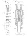
- FIG. 1shows an exploded, partial cross-sectional view of a first embodiment of the transfer system.
- FIG. 2shows a cross-sectional view of the transfer system in an assembled state with a transfer device and a receiver device coupled to one another.
- FIG. 3shows a cross-sectional view of the transfer device.
- FIG. 4shows a cross-sectional view of the receiver device.
- FIG. 5shows the transfer device positioned adjacent the receiver device just prior to coupling of the two devices.
- FIG. 6shows the transfer device coupled to the receiver device.
- FIGS. 7 and 8show an alternative embodiment of the transfer system.
- FIGS. 9 and 10show yet another embodiment of the transfer system.
- FIGS. 11 and 12show yet another embodiment of the transfer system.
- a transfer systemthat can be used to transfer a substance between a pair of vessels in a manner that avoids contamination.
- FIG. 1shows an exploded, partial cross-sectional view of a first embodiment of the transfer system 100 , which includes a transfer device 110 and a receiver device 115 .
- the transfer device 110 and the receiver device 115are configured to be removably coupled to one another for transferring a substance therebetween.
- the transfer device 110is described herein as the device from which the substance is transferred and the receiver device 115 is described as the device for which the substance is transferred to. It should be appreciated, however, that the transfer device 110 can be configured to receive the substance from the receiver device 115 such that the transfer device 110 is the receiving member and the receiver device 115 is the transfer member.
- the cannula-based housing described belowcan be on the receiving side of the substance.
- the nomenclature of “transfer” and “receiver”are used in an exemplary manner and are not to be considered limiting.
- the transfer system 110can also be used for bi-directional transfer of the substance across the system such that each device 110 and 115 can be both a transfer device and a receiver device.
- FIG. 2shows a cross-sectional view of the transfer system 100 in an assembled state with the transfer device 110 and the receiver device 115 coupled to one another.
- the transfer system 100is configured to transfer any of a variety of substances, including, but not limited to, medical fluids, drugs and body fluids including blood, from a first vessel 117 to a second vessel 118 .
- the transfer system 100can also be configured to transfer the substance from the second vessel 118 to the first vessel 117 .
- the transfer system 100can transfer blood from a vessel 118 comprised of a catheter in a patient to a vessel 117 comprised of a syringe.
- the first vessel 117 and the second vessel 118are both schematically represented using boxes labeled 117 and 118 in FIGS. 1 and 2 .
- the vessels 117 and 118can be any type of container configured to permanently or temporarily hold, store, or transfer a fluid substance.
- the first and second vessels 117 and 118can each comprise, for example, an injection syringe, a blood collection container, an ampoule, a drug container, a drug vial adapter, a solution container, an injection port, a needle free valve, a y-connector, a catheter, any portion of an infusion or intravenous injection system, a blood vessel of a patient, etc.
- the transfer device 110is configured to be removably attached at a proximal end to the first vessel 117 and the receiver device 115 is configured to be removably attached at a distal end to the second vessel 118 .
- the first vessel 117can be fixedly attached to the transfer device 110 and the second vessel 118 fixedly attached to the receiver device 115 .
- the transfer system 100facilitates the transfer of a substance from the first vessel 117 to the second vessel 118 in a manner that avoids contamination and reduces the likelihood of the substance or gases emanating from said substance escaping into the environment. It should be appreciated that the terms “proximal” and “distal” are relative terms and should not be considered as limiting to the device.
- the transfer device 110includes a proximal housing 120 and a distal housing 125 that can be attached to one another to collectively form an outer housing for the transfer device 110 .
- the proximal housing 120 and distal housing 125collectively form an internal chamber 127 that is peripherally enclosed by walls of the outer housing.
- a coupler component 130is disposed on a proximal end of the proximal housing 120 for enabling the transfer device 110 to be fluidly coupled to the first vessel 117 , as described more fully below.
- a cannula 135 having a blunt distal tipextends through the internal chamber 127 along a central, longitudinal axis A of the transfer system 100 .
- the blunt distal tipped cannula 135can also be a sharply pointed cannula.
- a transfer septum 140is movably positioned within the internal chamber 127 .
- the transfer septumis designed to keep the contents of the internal chamber 127 from escaping outside the internal chamber 127 .
- the transfer septum 140provides a seal with the walls of the internal chamber 127 to prevent the substance from escaping into the surrounding environment.
- a biasing member 145such as a spring, is disposed in the internal chamber 127 between the transfer septum 140 and a portion of the proximal housing 120 , such as a proximal wall of the proximal housing 120 .
- the biasing member 145biases the transfer septum 140 toward a default position, such as at or near a distal end of the internal chamber 127 .
- the biasing member 145is shown in FIGS. 1 and 2 as a spring, but it should be appreciated that the biasing member 145 can be any structure or mechanism that provides a biasing force against the transfer septum 140 .
- the receiver device 115includes a housing 150 . As shown in FIG. 2 , the housing 150 defines an internal passageway 155 for the passage of fluid received via the transfer device 110 into the second vessel 118 .
- the receiver device 115further includes a receiver septum 160 disposed at a proximal end of the housing 150 in the pathway of the passageway 155 .
- the receiver septum 160maintains an enclosure of housing 150 and passageway 155 such that the contents of passageway 155 cannot exit or otherwise escape from housing 150 except by means of the cannula 135 passing through the receiver septum 160 .
- a slit 165extends longitudinally through the receiver septum 160 along the axis A.
- the slit 165can be manufactured such that slit 165 remains closed in a default state to prevent the flow of fluid therethrough unless the slit 165 is manually opened.
- the receiver septum 160can be manufactured of a polymeric and resilient material that is able to provide bulk resilience to maintain the closed, natural state of the slit 165 .
- the slit 165can be manually opened by inserting the cannula 135 of the transfer device 110 through the slit 165 upon coupling of the transfer device and the receiver device. In this manner, the cannula 135 provides a fluid pathway between the transfer device 110 and the receiver device 115 , as described more fully below. It should be appreciated that should cannula 135 be sharply tipped, a pre-formed slit 165 in receiver septum 160 may not be a required element.
- the coupler component 130comprises any type of mechanism that can be coupled to the first vessel 117 .
- the coupler component 130is a female Luer lock, female Luer slip type or other form designed for the removable attachment of first vessel 117 .
- the coupler component 130could also be configured as a male Luer lock, male Luer slip connector, or other form designed for the removable attachment of first vessel 117 .
- the couplercould be an integrally molded part of another device or attached by bonding, welding or other means to fixedly attach two parts.
- An entry chamber 305is disposed within the proximal end of the proximal housing 120 and communicates with the first vessel 117 (shown in FIGS. 1 and 2 ) when attached to the transfer device 110 , such as via a syringe that is disposed in the entry chamber upon coupling to the first vessel 117 .
- the entry chamber 305also communicates with a transfer passageway 310 that extends axially through the cannula 135 .
- the transfer passageway 310communicates with an aperture 307 at the distal end of the cannula 135 for transfer of fluid out of the cannula 135 .
- the transfer septum 140is movably disposed within the internal chamber 127 .
- the transfer septum 140is configured to slidably move within the internal chamber 127 along the directions represented by the arrows D in FIG. 3 .
- the biasing member 145biases the transfer septum 140 toward a distal-most position within the internal chamber 127 such that the transfer septum 140 is in a distal-most position as a default position.
- the transfer septum 140includes one or more sealing portions that sealingly engage the internal walls of the chamber 127 .
- the structural configuration of the sealing portionscan vary.
- the sealing portionscomprise annular protrusions 315 peripherally located on the transfer septum 140 .
- the protrusions 315can serve a variety of purposes.
- the distal-most protrusion 315 afunctions as a mechanical stop that engages a shoulder on the housing to prevent the transfer septum 140 from being expelled out of the housing of the transfer device 110 .
- the protrusions 315can also function as o-ring type seals that sealingly engage an internal wall of the internal chamber 127 to prevent fluid (liquid or gas) from escaping from the internal chamber 127 .
- the protrusions 315form a fluid-proof seal that prevents fluid from escaping from the internal chamber 127 .
- the transfer septum 140has a distal surface 320 and a proximal surface 325 .
- the transfer septum 140has a size and position such that there is a space between the distal surface 320 and a distal end 330 of the transfer device housing, as is shown in FIG. 3 .
- the distal surface 320 of the transfer septum 140can be positioned flush with the distal end 330 of the transfer device housing or can at least partially or entirely protrude distally outward from the transfer device housing.
- the distal surface 320can vary in contour.
- the distal surface 320can be flat or it can be convex such that the surface bows outward in a distal direction.
- a slit 335extends longitudinally through the transfer septum 140 along the axis A in the same manner as the slit 165 in the receiver septum 160 .
- the transfer septum 140can be manufactured of a polymeric and resilient material that provides bulk resilience to maintain a natural, closed state of the slit 335 .
- the slit 335can be penetrated by the cannula 135 .
- a distal region of the cannula 335is positioned within the slit 335 when the transfer septum is in the default position, as shown in FIG. 3 . That is, the cannula penetrates the slit 335 when the transfer septum 140 is in the default position.
- the distal region of the cannula 135is positioned outside of the transfer septum 140 when the transfer septum 140 is in the default position.
- the distal tip (represented by lines 340 in FIG. 3 ) of the cannula 135does not penetrate the slit 335 . It should be appreciated that should cannula 135 be sharply tipped a pre-formed slit 335 in transfer septum 140 may not be a required element.
- the transfer of fluid out of the distal end of the transfer device 110can be accomplished primarily through the connection of the transfer device 110 to a receiver device such as the receiver device 115 .
- the two devicescan mate via two complimentary luer fittings, e.g. the male luer of a syringe will mate to a female luer on a catheter, stopcock, needle-free valve etc.
- the lueris a standardized connector within the medical community. The specifications for a luer can be found in ANSI/HIMA MD70.1 and ISO 594 standards.
- the distal end of the transfer device housinghas an internal diameter that is smaller than the outside diameter of a female luer in order to prevent or inhibit a female luer from being inserted into the distal end of the transfer device housing.
- a female lueris an open ended connector.
- the proximal end of the receiver device 115is generally a female luer that has been modified to include a septum that seals with the transfer device 110 .
- the transfer device housingcan mate with the modified female luer to achieve the intended safe transfer of fluids.
- the receiver device 115is now described in more detail with reference to FIG. 4 , which shows a cross-sectional view of the receiver device 115 .
- the receiver device 115includes a housing 150 and a receiver septum 160 mounted at a proximal end of the housing 150 .
- the receiver septum 160includes a slit 165 that is penetrated by the cannula 135 when the receiver device 115 is coupled to the transfer device 110 , as described more fully below.
- the receiver septum 160has a proximal surface 402 that can be flat, concave, or convex in shape.
- An attachment structure 405is located on the receiver device 115 for attaching to a corresponding structure on the transfer device 110 .
- the attachment structure 405can comprise any structure or mechanism for removably attaching a first component to a second component, such as threads, compression fit, a latching mechanism, etc.
- the receiver device 115can be coupled at a distal end to the second vessel 118 .
- the internal passageway 155 of the transfer device 115communicates with the second vessel 118 .
- FIGS. 5 and 6show schematic representations of the transfer device 110 and the receiver device 115 .
- FIG. 5shows the transfer device 110 positioned adjacent the receiver device 115 just prior to coupling of the two devices.
- the biasing member 145maintains the transfer septum 140 in its default distal-most position.
- the transfer device 110 and receiver device 115are coupled to one another as follows.
- the receiver device 115is first oriented such that the distal surface 320 of the transfer septum 140 faces the proximal surface 402 of the receiver septum 160 , as shown in FIG. 5 .
- the receiver device 115is moved toward the transfer device 110 (as represented by the arrow 510 in FIG. 5 ) such that the proximal surface 402 of the receiver septum 160 abuts the distal surface 320 of the transfer septum 140 .
- the proximal surface 402 and the distal surface 320are in juxtaposed contact with one another.
- the receiver device 115is then moved into the transfer device 110 (as represented by the arrows 610 in FIG. 6 ) such that the receiver septum 160 pushes the transfer septum 140 in the directions of the arrows 610 .
- a sufficient forceis exerted against the transfer septum 140 to overcome the biasing force exerted by the biasing member 145 and thereby slide the transfer septum 140 upward (with respect to FIG. 6 ) into the internal cavity 127 of the transfer device 110 .
- the transfer septum 140moves upward, the distal surface 320 of the transfer septum 140 moves upwardly past the distal tip of the cannula 135 .
- the cannula 135penetrates the slit in the receiver septum 160 until the distal tip of the cannula 135 communicates with the transfer passageway 155 in the receiver device 115 , as shown in FIG. 6 .
- the cannula 135provides a fluid passageway between the entry chamber 305 of the transfer device 110 and the internal passageway 155 of the receiver device 115 .
- the protrusions 315slide along the inner walls of chamber 127 and they form a compression sliding seal to continuously maintain a sealed internal chamber 127 .
- the first vessel 117is coupled to the transfer device 110 and the second vessel 118 is coupled to the receiver device 115 .
- the first vessel 117communicates with the entry chamber 305 of the transfer device 110 and the second vessel 118 communicates with the internal passageway 155 of the receiver device 115 .
- the fluid substanceis transferred from the first vessel 117 , into the entry chamber 305 , through the cannula 135 , into the internal passageway 155 , and into the second vessel 118 .
- the transfer septum 140 and the receiver septum 160remain in juxtaposed contact with one another.
- the transfer system 700includes a transfer device 710 and a receiver device 715 .
- the transfer device 710includes an outer housing similar to the outer housing of the previous embodiment.
- a biasing member 720exerts a biasing force against a transfer septum 725 to maintain the transfer septum 725 in a default state.
- the transfer septum 725includes a slit that can be passed through by a cannula 727 of the transfer device 710 .
- An attachment region 730 of the transfer septum 725is fixedly attached to the outer housing of the transfer device 110 in a sealing manner. That is, the attachment region 730 provides a fluid-tight seal between the transfer septum 725 and the outer housing of the transfer device 110 . In this manner, a sealed chamber 127 is located within the outer housing proximal of the transfer septum 725 .
- the receiver device 715includes a housing 740 that defines an internal passageway 745 .
- a receiver septum 750is attached to the housing 740 and includes a slit that can be passed through by the cannula 727 when the transfer device 710 and the receiver device 715 are coupled to one another.
- the transfer septum 725 and the receiver septum 750need not be slit if the cannula 727 has a sharp tip.
- the receiver device 715is inserted into the transfer device 710 such that a proximal surface 755 of the receiver septum 750 abuts a distal surface 760 of the transfer septum 725 .
- the receiver septum 750exerts a force against the transfer septum 725 to overcome the force exerted by the biasing member 720 and push the transfer septum 725 upward (relative to FIG. 7 ) into the housing of the transfer device 710 .
- the attachment region 730 of the transfer septum 725is fixedly attached to the housing of the transfer device 710 .
- the receiver device 715pushes upward into the transfer device 710 , at least a portion of the transfer septum 725 moves upwardly into the transfer device housing while the attachment region 730 of the transfer septum 725 remains fixed relative to the transfer housing, as best shown in FIG. 8 .
- the attachment region 730 of the septumcreates a sealed chamber 127 inside the housing to prevent the escape of any substance from the chamber into the environment.
- the distal surface 760 of the transfer septum 725remains in juxtaposed contact with the proximal surface 755 of the receiver septum 750 .
- the transfer system 700can be used to transfer a substance from the first vessel 117 to the second vessel 118 via the cannula 727 .
- FIGS. 9 and 10show yet another embodiment of the transfer system, referred to as the transfer system 900 , which includes a transfer device 910 and a receiver device 915 .
- the transfer device 910includes a proximal housing 920 and a distal housing 925 that is slidably attached to the proximal housing 920 .
- a transfer septum 935is fixedly attached to the distal housing 925 .
- a cavity 937is located in the distal housing 925 just below the transfer septum 935 and is sized to receive at least a portion of the receiver device 915 .
- a biasing member 940is positioned inside the proximal housing 920 and exerts a force against the transfer septum 935 to maintain the transfer septum 935 and the distal housing 925 in a default, distal position, as shown in FIG. 9 .
- the transfer septum 935 and/or the distal housing 925includes a shoulder or other structure that engages the proximal housing 920 to prevent the distal housing 925 and attached transfer septum 935 from being expelled from the proximal housing 920 .
- the distal housing 925can slide relative to the proximal housing 920 along the directions represented by the arrows 933 in FIG. 9 .
- a latching mechanism 942is attached to the proximal housing 920 .
- the latching mechanism 942removably engages a portion of the distal housing 925 and provides a means of fixing the position of the distal housing 925 relative to the proximal housing 920 when sliding movement is not desired.
- the latching mechanism 942can be disengaged to permit the distal housing 925 to slide relative to the proximal housing 920 .
- the receiver device 915includes a housing 950 and a receiver septum 955 as in the previous embodiments.
- An internal passageway 960is contained in the housing 950 .
- receiver device 915is inserted into the cavity 937 of the transfer device 937 until the receiver septum 955 is in juxtaposed contact with the transfer septum 935 .
- the latching mechanism 942is released and the receiver device 915 is pushed upwardly (relative to FIG. 9 ) into the transfer device 910 to force the distal housing 925 and attached transfer septum 935 to overcome the biasing force of spring 940 to slide upwardly relative to the proximal housing 920 , as shown in FIG. 10 .
- the transfer septum 935 and the receiver septum 955remain in juxtaposed contact with one another.
- the cannula 960passes through the slits in both septums and provides a fluid passageway between the first vessel 117 and the second vessel 118 , which are attached to the transfer device 910 and the receiver device 915 , respectively.
- the transfer septum 935 and the receiver septum 955need not be slit if the cannula 960 has a sharp tip.
- FIGS. 11 and 12show another embodiment of the transfer system 100 in which the receiver device 115 includes first and second seals or septums 160 a and 160 b , respectively.
- the first septum 160 ais positioned at or near a proximal edge of the receiver device 115 and can include a slit as in the previous embodiments.
- the second septum 160 bis positioned distally of the first septum 160 b such that an air space 1110 is interposed between the first and second septums.
- the first and second septumsare configured and positioned such that at least the distal end of the cannula 135 passes at least partially through both septums when the receiver device 115 is coupled to the transfer device 110 , as described in more detail below with reference to FIG. 12 .
- At least one of the functions of both septums 160 a and 160 bis to wipe the cannula as the cannula withdraws in the proximal direction out of the receiver device 115 .
- the second septum 160 bprovides a first wipe to the cannula as the cannula withdraws and the first septum 160 a provides a second wipe.
- the air space 1110acts as a repository for any fluid that passes through the second septum 160 b during withdrawal of the cannula from the receiver device 110 .
- the structural configurations of the septumscan vary.
- the septums 160 a and 160 bcan be manufactured of separate pieces of material, as shown in FIGS. 11 and 12 such that two separate, distinct septums are used.
- the septums 160 a and 160 bare connected to one another along at least a portion of the septums with the air gap 1110 still being interposed between the two septums.
- the two septums 160 a and 160 bcan be formed from a single piece of material or multiple pieces of material.
- one or both of the septumsis replaced by a wiping member that can be any structure or device configured to wipe the cannula during withdrawal of the cannula.
- one or both of the septumscan be replaced by a duckbill-type valve or seal that wipes the cannula.
- Other types of structurescan be used as long as the structure provides two separate wipes and an air space 1110 therebetween.
- the transfer device 110is coupled to the receiver device 115 in the manner described above with respect to the previous embodiments.
- the distal end of the cannula 135first passes through the first septum 160 a and then passes through the second septum 160 b .
- the distal end of the cannula 135then communicates with the passageway 155 in the receiver device 115 , as shown in FIG. 12 . Fluid can then be transferred between the transfer device 110 and the receiver device 115 via the cannula 135 .
- the transfer device 110can then be de-coupled from the receiver device 115 such that the cannula 135 withdraws in a distal direction out of the receiver device 115 .
- the distal end of the cannula 135first passes through the second septum 160 b , which wipes the cannula 135 during withdrawal of the cannula 135 .
- the cannula 135continues to withdraw from the receiver device 115 , the cannula 135 next passes through the first septum 160 a , which provides a second wipe to the cannula 135 . In this manner, the device shown in FIGS. 11 and 12 provide additional wiping of the cannula 135 .
Landscapes
- Health & Medical Sciences (AREA)
- General Health & Medical Sciences (AREA)
- Heart & Thoracic Surgery (AREA)
- Veterinary Medicine (AREA)
- Public Health (AREA)
- Life Sciences & Earth Sciences (AREA)
- Animal Behavior & Ethology (AREA)
- Pharmacology & Pharmacy (AREA)
- Chemical Kinetics & Catalysis (AREA)
- Chemical & Material Sciences (AREA)
- Clinical Laboratory Science (AREA)
- Pulmonology (AREA)
- Engineering & Computer Science (AREA)
- Anesthesiology (AREA)
- Biomedical Technology (AREA)
- Hematology (AREA)
- Infusion, Injection, And Reservoir Apparatuses (AREA)
Abstract
Description
Claims (13)
Priority Applications (2)
| Application Number | Priority Date | Filing Date | Title |
|---|---|---|---|
| US12/688,340US8157784B2 (en) | 2005-05-13 | 2010-01-15 | Medical substance transfer system |
| US13/448,201US9198831B2 (en) | 2005-05-13 | 2012-04-16 | Medical substance transfer system |
Applications Claiming Priority (5)
| Application Number | Priority Date | Filing Date | Title |
|---|---|---|---|
| US68108305P | 2005-05-13 | 2005-05-13 | |
| US68519305P | 2005-05-26 | 2005-05-26 | |
| US72463805P | 2005-10-07 | 2005-10-07 | |
| US11/435,274US7648491B2 (en) | 2005-05-13 | 2006-05-15 | Medical substance transfer system |
| US12/688,340US8157784B2 (en) | 2005-05-13 | 2010-01-15 | Medical substance transfer system |
Related Parent Applications (1)
| Application Number | Title | Priority Date | Filing Date |
|---|---|---|---|
| US11/435,274ContinuationUS7648491B2 (en) | 2005-05-13 | 2006-05-15 | Medical substance transfer system |
Related Child Applications (1)
| Application Number | Title | Priority Date | Filing Date |
|---|---|---|---|
| US13/448,201ContinuationUS9198831B2 (en) | 2005-05-13 | 2012-04-16 | Medical substance transfer system |
Publications (2)
| Publication Number | Publication Date |
|---|---|
| US20100121305A1 US20100121305A1 (en) | 2010-05-13 |
| US8157784B2true US8157784B2 (en) | 2012-04-17 |
Family
ID=37431969
Family Applications (3)
| Application Number | Title | Priority Date | Filing Date |
|---|---|---|---|
| US11/435,274Expired - Fee RelatedUS7648491B2 (en) | 2005-05-13 | 2006-05-15 | Medical substance transfer system |
| US12/688,340Active2027-02-15US8157784B2 (en) | 2005-05-13 | 2010-01-15 | Medical substance transfer system |
| US13/448,201Active2028-01-27US9198831B2 (en) | 2005-05-13 | 2012-04-16 | Medical substance transfer system |
Family Applications Before (1)
| Application Number | Title | Priority Date | Filing Date |
|---|---|---|---|
| US11/435,274Expired - Fee RelatedUS7648491B2 (en) | 2005-05-13 | 2006-05-15 | Medical substance transfer system |
Family Applications After (1)
| Application Number | Title | Priority Date | Filing Date |
|---|---|---|---|
| US13/448,201Active2028-01-27US9198831B2 (en) | 2005-05-13 | 2012-04-16 | Medical substance transfer system |
Country Status (2)
| Country | Link |
|---|---|
| US (3) | US7648491B2 (en) |
| WO (1) | WO2006124756A2 (en) |
Cited By (62)
| Publication number | Priority date | Publication date | Assignee | Title |
|---|---|---|---|---|
| US8608723B2 (en) | 2009-11-12 | 2013-12-17 | Medimop Medical Projects Ltd. | Fluid transfer devices with sealing arrangement |
| US8684994B2 (en) | 2010-02-24 | 2014-04-01 | Medimop Medical Projects Ltd. | Fluid transfer assembly with venting arrangement |
| US8752598B2 (en) | 2011-04-17 | 2014-06-17 | Medimop Medical Projects Ltd. | Liquid drug transfer assembly |
| US8753325B2 (en) | 2010-02-24 | 2014-06-17 | Medimop Medical Projects, Ltd. | Liquid drug transfer device with vented vial adapter |
| US8852145B2 (en) | 2010-11-14 | 2014-10-07 | Medimop Medical Projects, Ltd. | Inline liquid drug medical device having rotary flow control member |
| US8905994B1 (en) | 2011-10-11 | 2014-12-09 | Medimop Medical Projects, Ltd. | Valve assembly for use with liquid container and drug vial |
| USD720451S1 (en) | 2012-02-13 | 2014-12-30 | Medimop Medical Projects Ltd. | Liquid drug transfer assembly |
| US8979792B2 (en) | 2009-11-12 | 2015-03-17 | Medimop Medical Projects Ltd. | Inline liquid drug medical devices with linear displaceable sliding flow control member |
| US8998875B2 (en) | 2009-10-01 | 2015-04-07 | Medimop Medical Projects Ltd. | Vial assemblage with vial and pre-attached fluid transfer device |
| USD734868S1 (en) | 2012-11-27 | 2015-07-21 | Medimop Medical Projects Ltd. | Drug vial adapter with downwardly depending stopper |
| USD737436S1 (en) | 2012-02-13 | 2015-08-25 | Medimop Medical Projects Ltd. | Liquid drug reconstitution assembly |
| US9180070B2 (en) | 2012-02-02 | 2015-11-10 | Becton Dickinson Holdings Pte. Ltd. | Adaptor for coupling to a medical container |
| USD747650S1 (en) | 2013-08-05 | 2016-01-19 | Becton Dickinson France | Blocking closure for container |
| US9283324B2 (en) | 2012-04-05 | 2016-03-15 | Medimop Medical Projects, Ltd | Fluid transfer devices having cartridge port with cartridge ejection arrangement |
| US9339438B2 (en) | 2012-09-13 | 2016-05-17 | Medimop Medical Projects Ltd. | Telescopic female drug vial adapter |
| USD757933S1 (en) | 2014-09-11 | 2016-05-31 | Medimop Medical Projects Ltd. | Dual vial adapter assemblage |
| USD765837S1 (en) | 2013-08-07 | 2016-09-06 | Medimop Medical Projects Ltd. | Liquid transfer device with integral vial adapter |
| USD767124S1 (en) | 2013-08-07 | 2016-09-20 | Medimop Medical Projects Ltd. | Liquid transfer device with integral vial adapter |
| US9549873B2 (en) | 2012-02-02 | 2017-01-24 | Becton Dickinson Holdings Pte. Ltd. | Adaptor for coupling to a medical container |
| US9668939B2 (en) | 2012-02-02 | 2017-06-06 | Becton Dickinson Holdings Pte. Ltd. | Adaptor for coupling with a medical container |
| US9750926B2 (en) | 2010-05-17 | 2017-09-05 | Icu Medical, Inc. | Medical connectors and methods of use |
| US9795536B2 (en) | 2012-08-26 | 2017-10-24 | Medimop Medical Projects, Ltd. | Liquid drug transfer devices employing manual rotation for dual flow communication step actuations |
| US9801786B2 (en) | 2013-04-14 | 2017-10-31 | Medimop Medical Projects Ltd. | Drug container closure for mounting on open-topped drug container to form drug reconstitution assemblage for use with needleless syringe |
| USD801522S1 (en) | 2015-11-09 | 2017-10-31 | Medimop Medical Projects Ltd. | Fluid transfer assembly |
| US9839580B2 (en) | 2012-08-26 | 2017-12-12 | Medimop Medical Projects, Ltd. | Liquid drug transfer devices |
| US9884176B2 (en) | 2004-11-05 | 2018-02-06 | Icu Medical, Inc. | Medical connector |
| US9943463B2 (en) | 2013-05-10 | 2018-04-17 | West Pharma. Services IL, Ltd. | Medical devices including vial adapter with inline dry drug module |
| US10058483B2 (en) | 2008-05-14 | 2018-08-28 | J&J Solutions, Inc. | Systems and methods for safe medicament transport |
| USD832430S1 (en) | 2016-11-15 | 2018-10-30 | West Pharma. Services IL, Ltd. | Dual vial adapter assemblage |
| US10195112B2 (en) | 2012-11-26 | 2019-02-05 | Becton Dickinson France | Adaptor for multidose medical container |
| US10238576B2 (en) | 2010-05-27 | 2019-03-26 | J & J Solutions, Inc. | Closed fluid transfer system |
| US10278897B2 (en) | 2015-11-25 | 2019-05-07 | West Pharma. Services IL, Ltd. | Dual vial adapter assemblage including drug vial adapter with self-sealing access valve |
| US10285907B2 (en) | 2015-01-05 | 2019-05-14 | West Pharma. Services IL, Ltd. | Dual vial adapter assemblages with quick release drug vial adapter for ensuring correct usage |
| US10357429B2 (en) | 2015-07-16 | 2019-07-23 | West Pharma. Services IL, Ltd. | Liquid drug transfer devices for secure telescopic snap fit on injection vials |
| US10646404B2 (en) | 2016-05-24 | 2020-05-12 | West Pharma. Services IL, Ltd. | Dual vial adapter assemblages including identical twin vial adapters |
| US10688295B2 (en) | 2013-08-07 | 2020-06-23 | West Pharma. Services IL, Ltd. | Liquid transfer devices for use with infusion liquid containers |
| US10765604B2 (en) | 2016-05-24 | 2020-09-08 | West Pharma. Services IL, Ltd. | Drug vial adapter assemblages including vented drug vial adapter and vented liquid vial adapter |
| US10772798B2 (en) | 2016-12-06 | 2020-09-15 | West Pharma Services Il, Ltd. | Liquid transfer device with integral telescopic vial adapter for use with infusion liquid container and discrete injection vial |
| US10806667B2 (en) | 2016-06-06 | 2020-10-20 | West Pharma. Services IL, Ltd. | Fluid transfer devices for filling drug pump cartridges with liquid drug contents |
| US10806671B2 (en) | 2016-08-21 | 2020-10-20 | West Pharma. Services IL, Ltd. | Syringe assembly |
| USD903864S1 (en) | 2018-06-20 | 2020-12-01 | West Pharma. Services IL, Ltd. | Medication mixing apparatus |
| US10945921B2 (en) | 2017-03-29 | 2021-03-16 | West Pharma. Services IL, Ltd. | User actuated liquid drug transfer devices for use in ready-to-use (RTU) liquid drug transfer assemblages |
| USD917693S1 (en) | 2018-07-06 | 2021-04-27 | West Pharma. Services IL, Ltd. | Medication mixing apparatus |
| USD923782S1 (en) | 2019-01-17 | 2021-06-29 | West Pharma. Services IL, Ltd. | Medication mixing apparatus |
| USD923812S1 (en) | 2019-01-16 | 2021-06-29 | West Pharma. Services IL, Ltd. | Medication mixing apparatus |
| US11168818B2 (en) | 2011-09-09 | 2021-11-09 | Icu Medical, Inc. | Axially engaging medical connector system that inhibits fluid penetration between mating surfaces |
| US11207514B2 (en) | 2016-09-26 | 2021-12-28 | Terumo Kabushiki Kaisha | Male connector, medical device, and connection method |
| US11273297B2 (en) | 2017-03-24 | 2022-03-15 | Terumo Kabushiki Kaisha | Medical device |
| USD954253S1 (en) | 2019-04-30 | 2022-06-07 | West Pharma. Services IL, Ltd. | Liquid transfer device |
| US11364372B2 (en) | 2013-12-11 | 2022-06-21 | Icu Medical, Inc. | Check valve |
| USD956958S1 (en) | 2020-07-13 | 2022-07-05 | West Pharma. Services IL, Ltd. | Liquid transfer device |
| US11452856B2 (en) | 2017-03-24 | 2022-09-27 | Terumo Kabushiki Kaisha | Medical device |
| US11491084B2 (en) | 2018-03-27 | 2022-11-08 | Terumo Kabushiki Kaisha | Medical device |
| US11559428B2 (en) | 2013-05-03 | 2023-01-24 | Clearside Biomedical, Inc. | Apparatus and methods for ocular injection |
| US11642285B2 (en) | 2017-09-29 | 2023-05-09 | West Pharma. Services IL, Ltd. | Dual vial adapter assemblages including twin vented female vial adapters |
| US11752101B2 (en) | 2006-02-22 | 2023-09-12 | Clearside Biomedical, Inc. | Ocular injector and methods for accessing suprachoroidal space of the eye |
| US11918542B2 (en) | 2019-01-31 | 2024-03-05 | West Pharma. Services IL, Ltd. | Liquid transfer device |
| US12090088B2 (en) | 2010-10-15 | 2024-09-17 | Clearside Biomedical, Inc. | Device for ocular access |
| US12127975B2 (en) | 2016-08-12 | 2024-10-29 | Clearside Biomedical, Inc. | Devices and methods for adjusting the insertion depth of a needle for medicament delivery |
| US12274670B2 (en) | 2019-04-09 | 2025-04-15 | West Pharma. Services IL, Ltd. | Liquid transfer device with integrated syringe |
| US12427091B2 (en) | 2019-01-18 | 2025-09-30 | West Pharma. Services IL, Ltd. | Liquid transfer devices for use with intravenous (IV) bottles |
| US12440661B2 (en) | 2022-05-18 | 2025-10-14 | Icu Medical, Inc. | Medical fluid transfer device |
Families Citing this family (95)
| Publication number | Priority date | Publication date | Assignee | Title |
|---|---|---|---|---|
| HK1077154A2 (en) | 2003-12-30 | 2006-02-03 | Icu Medical, Inc. | Valve assembly |
| US20070088293A1 (en) | 2005-07-06 | 2007-04-19 | Fangrow Thomas F Jr | Medical connector with closeable male luer |
| US7998134B2 (en) | 2007-05-16 | 2011-08-16 | Icu Medical, Inc. | Medical connector |
| BRPI0717401A2 (en) | 2006-10-25 | 2013-11-12 | Icu Medical Inc | CONNECTOR FOR MEDICAL USE |
| US20100152674A1 (en)* | 2007-04-30 | 2010-06-17 | Medtronic Minimed, Inc | Needle inserting and fluid flow connection for infusion medium delivery system |
| US8287513B2 (en)* | 2007-09-11 | 2012-10-16 | Carmel Pharma Ab | Piercing member protection device |
| US20110106046A1 (en)* | 2008-05-02 | 2011-05-05 | Terumo Kabushiki Kaisha | Connector assembly |
| US9370621B2 (en)* | 2008-12-16 | 2016-06-21 | Medtronic Minimed, Inc. | Needle insertion systems and methods |
| US9168366B2 (en) | 2008-12-19 | 2015-10-27 | Icu Medical, Inc. | Medical connector with closeable luer connector |
| US8512309B2 (en)* | 2009-01-15 | 2013-08-20 | Teva Medical Ltd. | Vial adapter element |
| US8523826B2 (en)* | 2009-02-13 | 2013-09-03 | Cytyc Corporation | Luer-type needle-free valve fitting with bypass |
| US8403822B2 (en)* | 2009-02-20 | 2013-03-26 | Cytyc Corporation | Passive vent for brachytherapy balloon catheters |
| WO2010109449A1 (en) | 2009-03-22 | 2010-09-30 | Elcam Medical Agricultural Cooperative Association Ltd. | Closed male luer connector |
| US8454579B2 (en) | 2009-03-25 | 2013-06-04 | Icu Medical, Inc. | Medical connector with automatic valves and volume regulator |
| AU2010262752B2 (en)* | 2009-06-17 | 2013-08-22 | Unitract Syringe Pty Ltd | Syringe adapter |
| US8323249B2 (en) | 2009-08-14 | 2012-12-04 | The Regents Of The University Of Michigan | Integrated vascular delivery system |
| US8932256B2 (en) | 2009-09-02 | 2015-01-13 | Medtronic Minimed, Inc. | Insertion device systems and methods |
| US8900190B2 (en) | 2009-09-02 | 2014-12-02 | Medtronic Minimed, Inc. | Insertion device systems and methods |
| US9662271B2 (en) | 2009-10-23 | 2017-05-30 | Amgen Inc. | Vial adapter and system |
| US8721614B2 (en)* | 2009-10-28 | 2014-05-13 | Terumo Kabushiki Kaisha | Connector assembly |
| US8998858B2 (en) | 2009-12-29 | 2015-04-07 | Medtronic Minimed, Inc. | Alignment and connection systems and methods |
| US8998840B2 (en) | 2009-12-30 | 2015-04-07 | Medtronic Minimed, Inc. | Connection and alignment systems and methods |
| US8858500B2 (en) | 2009-12-30 | 2014-10-14 | Medtronic Minimed, Inc. | Engagement and sensing systems and methods |
| US9039653B2 (en) | 2009-12-29 | 2015-05-26 | Medtronic Minimed, Inc. | Retention systems and methods |
| US8435209B2 (en) | 2009-12-30 | 2013-05-07 | Medtronic Minimed, Inc. | Connection and alignment detection systems and methods |
| US11497850B2 (en) | 2009-12-30 | 2022-11-15 | Medtronic Minimed, Inc. | Connection and alignment detection systems and methods |
| US9421321B2 (en) | 2009-12-30 | 2016-08-23 | Medtronic Minimed, Inc. | Connection and alignment systems and methods |
| US20120215163A1 (en) | 2009-12-30 | 2012-08-23 | Medtronic Minimed, Inc. | Sensing systems and methods |
| USD644731S1 (en) | 2010-03-23 | 2011-09-06 | Icu Medical, Inc. | Medical connector |
| EP2550058B1 (en)* | 2010-05-06 | 2014-03-26 | ICU Medical, Inc. | Medical connector with closeable luer connector |
| US8814833B2 (en) | 2010-05-19 | 2014-08-26 | Tangent Medical Technologies Llc | Safety needle system operable with a medical device |
| WO2011146769A2 (en) | 2010-05-19 | 2011-11-24 | Tangent Medical Technologies Llc | Integrated vascular delivery system |
| JP2014511249A (en)* | 2011-03-04 | 2014-05-15 | デュオジェクト・メディカル・システムズ・インコーポレイテッド | Easy transfer system |
| CA2831100C (en) | 2011-03-31 | 2020-02-18 | Mark Dominis Holt | Vial adapter and system |
| EP2699295B1 (en) | 2011-04-18 | 2022-06-08 | Dr. Py Institute LLC | Needle with closure and method |
| FR2978353B1 (en) | 2011-07-29 | 2013-08-02 | Vygon | ANTI-DROP DIRECT FLOW CONNECTORS WITH SECURE LATCHING |
| EP2838602A4 (en) | 2012-04-17 | 2016-04-20 | Py Inst Llc Dr | Self closing connector |
| US10351271B2 (en) | 2012-05-01 | 2019-07-16 | Dr. Py Institute Llc | Device for connecting or filling and method |
| EP2844904A4 (en) | 2012-05-01 | 2016-05-25 | Py Inst Llc Dr | DEVICE FOR CONNECTING OR FILLING AND METHOD |
| US9022950B2 (en) | 2012-05-30 | 2015-05-05 | Magnolia Medical Technologies, Inc. | Fluid diversion mechanism for bodily-fluid sampling |
| US9060724B2 (en) | 2012-05-30 | 2015-06-23 | Magnolia Medical Technologies, Inc. | Fluid diversion mechanism for bodily-fluid sampling |
| CA2876292A1 (en)* | 2012-06-13 | 2013-12-19 | Dr. Py Institute Llc | Device with penetrable septum and closure, and needle |
| US9204864B2 (en) | 2012-08-01 | 2015-12-08 | Magnolia Medical Technologies, Inc. | Fluid diversion mechanism for bodily-fluid sampling |
| EP2692328A1 (en) | 2012-08-03 | 2014-02-05 | Becton Dickinson France | Dose counting device for coupling with a medical container |
| EP2906269B1 (en) | 2012-10-11 | 2018-01-03 | Magnolia Medical Technologies, Inc. | System for delivering a fluid to a patient with reduced contamination |
| EP2916905A4 (en) | 2012-11-12 | 2016-11-09 | Icu Medical Inc | MEDICAL CONNECTION |
| CN109171766A (en) | 2012-11-30 | 2019-01-11 | 木兰医药技术股份有限公司 | Body fluid barrier means and the method for completely cutting off body fluid using body fluid barrier means |
| AU2013370416B2 (en)* | 2012-12-27 | 2017-08-31 | Medi-Physics, Inc. | Needle kit |
| JP6463726B2 (en) | 2013-03-15 | 2019-02-06 | ドクター ピー インスティチュート エルエルシー | Controlled non-separating filling instrument and method |
| JP6370364B2 (en) | 2013-03-15 | 2018-08-08 | アイシーユー・メディカル・インコーポレーテッド | Medical connector |
| US9414990B2 (en) | 2013-03-15 | 2016-08-16 | Becton Dickinson and Company Ltd. | Seal system for cannula |
| US9597260B2 (en) | 2013-03-15 | 2017-03-21 | Becton Dickinson and Company Ltd. | System for closed transfer of fluids |
| ES2780856T3 (en) | 2013-11-06 | 2020-08-27 | Becton Dickinson & Co Ltd | Medical connector having locking coupling |
| ES2780857T3 (en) | 2013-11-06 | 2020-08-27 | Becton Dickinson & Co Ltd | Connection device for a medical device |
| EP3065694B1 (en) | 2013-11-06 | 2020-04-29 | Becton Dickinson and Company Limited | System for closed transfer of fluids having connector |
| CA2929476C (en) | 2013-11-06 | 2019-01-22 | Becton Dickinson and Company Limited | System for closed transfer of fluids with a locking member |
| CA2937744C (en) | 2014-02-04 | 2022-08-09 | Icu Medical, Inc. | Self-priming systems and methods |
| EP3721854B1 (en) | 2014-03-03 | 2023-04-05 | Magnolia Medical Technologies, Inc. | Apparatus and methods for disinfection of a specimen container |
| CN106232082B (en) | 2014-04-16 | 2019-03-12 | 贝克顿迪金森有限公司 | Fluid delivery device with axially and rotatably movable parts |
| EP3134057B1 (en) | 2014-04-21 | 2018-06-27 | Becton Dickinson and Company Limited | Syringe adapter with compound motion disengagement |
| EP4091597A1 (en)* | 2014-04-21 | 2022-11-23 | Becton Dickinson and Company Limited | Syringe adapter with disconnection feedback mechanism |
| EP3398583A1 (en) | 2014-04-21 | 2018-11-07 | Becton Dickinson and Company Limited | System with adapter for closed transfer of fluids |
| EP3134058B1 (en) | 2014-04-21 | 2020-03-18 | Becton Dickinson and Company Limited | Fluid transfer device and packaging therefor |
| ES2792512T3 (en) | 2014-04-21 | 2020-11-11 | Becton Dickinson & Co Ltd | Fluid transfer device and packaging for it |
| AU2015249915B2 (en) | 2014-04-21 | 2017-11-30 | Becton Dickinson and Company Limited | System for closed transfer of fluids |
| BR112016024680B8 (en)* | 2014-04-21 | 2021-11-09 | Becton Dickinson & Co Ltd | Syringe adapter |
| CN110353993B (en) | 2014-04-21 | 2022-04-12 | 贝克顿迪金森有限公司 | Bottle stabilizer base with attachable bottle adapter |
| ES2702285T3 (en) | 2014-10-14 | 2019-02-28 | Becton Dickinson Co | Management of blood samples using open cell foam |
| EP4338668A1 (en) | 2014-10-14 | 2024-03-20 | Becton, Dickinson and Company | Blood sample management using open cell foam |
| USD793551S1 (en) | 2014-12-03 | 2017-08-01 | Icu Medical, Inc. | Fluid manifold |
| USD786427S1 (en) | 2014-12-03 | 2017-05-09 | Icu Medical, Inc. | Fluid manifold |
| WO2016201406A1 (en) | 2015-06-12 | 2016-12-15 | Bullington Gregory J | Devices and methods for syringe-based fluid transfer for bodily-fluid sampling |
| EP4249119A3 (en) | 2015-09-03 | 2023-11-29 | Magnolia Medical Technologies, Inc. | System for maintaining sterility of a specimen container |
| USD829896S1 (en) | 2015-09-15 | 2018-10-02 | Dr. Py Institute Llc | Septum |
| EP3349713B1 (en) | 2015-09-15 | 2023-11-01 | Dr. Py Institute LLC | Septum that decontaminates by interaction with penetrating element |
| US11648179B2 (en) | 2016-05-16 | 2023-05-16 | Haemonetics Corporation | Sealer-less plasma bottle and top for same |
| HUE054412T2 (en) | 2016-05-16 | 2021-09-28 | Haemonetics Corp | Sealer-less plasma bottle and top for same |
| EP3570931B1 (en) | 2017-01-17 | 2023-06-07 | Becton Dickinson and Company Limited | Syringe adapter with lock mechanism |
| IL268043B2 (en) | 2017-01-17 | 2023-10-01 | Becton Dickinson & Co Ltd | Connector for a closed fluid transfer system |
| CA3050433A1 (en) | 2017-01-17 | 2018-07-26 | Becton Dickinson and Company Limited | Syringe adapter with cap |
| AU2018210833B2 (en) | 2017-01-17 | 2023-05-04 | Becton Dickinson and Company Limited | Syringe adapter |
| ES2949067T3 (en) | 2017-01-17 | 2023-09-25 | Becton Dickinson & Co Ltd | Syringe adapter for closed fluid transfer |
| EP3628016B1 (en) | 2017-05-01 | 2025-01-01 | Michael V. Quinn | System for dosing and dispensing medication |
| EP4555929A3 (en) | 2017-09-12 | 2025-06-25 | Magnolia Medical Technologies, Inc. | Fluid control device |
| JP7229267B2 (en) | 2017-12-07 | 2023-02-27 | マグノリア メディカル テクノロジーズ,インコーポレイテッド | Fluid control device and method of use |
| US11389596B2 (en) | 2018-01-12 | 2022-07-19 | Becton, Dickinson And Company | Smart vial adapter and method |
| US11020318B2 (en)* | 2019-01-22 | 2021-06-01 | John Santos | Push release closed system drug transfer apparatus |
| WO2020163744A1 (en) | 2019-02-08 | 2020-08-13 | Magnolia Medical Technologies, Inc. | Devices and methods for bodily fluid collection and distribution |
| CN113784793B (en) | 2019-03-11 | 2023-09-19 | 木兰医药技术股份有限公司 | Fluid control device and method of using the same |
| US10945922B1 (en)* | 2019-09-26 | 2021-03-16 | Abyssal Systems, Inc. | Apparatus for creating a sealed conduit between separate volumes |
| CN114615964A (en)* | 2019-10-31 | 2022-06-10 | 纳卡特尔国际进出口股份责任有限公司 | Safety assembly for reconstituting, extracting and infusing medical fluids |
| GB201918663D0 (en) | 2019-12-17 | 2020-01-29 | Oribiotech Ltd | A connector |
| BR112023003392A2 (en)* | 2020-08-25 | 2023-04-11 | Becton Dickinson Co | MEMBRANE FOR CLOSED SYSTEM TRANSFER DEVICE |
| US20230211071A1 (en)* | 2021-12-30 | 2023-07-06 | Carefusion 303, Inc. | Anchorable medical fluid extension set system |
| WO2025178029A1 (en)* | 2024-02-20 | 2025-08-28 | テルモ株式会社 | Male connector |
Citations (54)
| Publication number | Priority date | Publication date | Assignee | Title |
|---|---|---|---|---|
| US3986508A (en) | 1973-08-22 | 1976-10-19 | Abcor, Inc. | Sterilizable, medical connector for blood processing |
| US4121585A (en) | 1977-01-24 | 1978-10-24 | Becker Jr Karl E | Anti backflow injection device |
| US4334551A (en) | 1979-04-30 | 1982-06-15 | Becton Dickinson & Company | Connector |
| US4436519A (en) | 1981-05-28 | 1984-03-13 | Argon Medical Corp. | Removable hemostasis valve |
| EP0126718A2 (en) | 1983-05-20 | 1984-11-28 | Bengt Gustavsson | A device for transferring a substance from one vessel to another and further to the intended application |
| WO1984004672A1 (en) | 1983-05-20 | 1984-12-06 | Bengt Gustavsson | A pressure balancing device for sealed vessels |
| US4610469A (en) | 1983-02-02 | 1986-09-09 | Steritech B.V. | Connector assembly for sterile connection or two internally sterile containers of tubings |
| US4895346A (en) | 1988-05-02 | 1990-01-23 | The Kendall Company | Valve assembly |
| US4960412A (en) | 1988-04-15 | 1990-10-02 | Universal Medical Instrument Corp. | Catheter introducing system |
| US5064416A (en) | 1988-05-26 | 1991-11-12 | Newgard Kent W | Self-occluding intravascular cannula assembly |
| US5092857A (en) | 1991-05-17 | 1992-03-03 | Fleischhacker John J | Hemostasis valve having support shoulders |
| US5100394A (en) | 1988-01-25 | 1992-03-31 | Baxter International Inc. | Pre-slit injection site |
| US5122123A (en) | 1991-01-30 | 1992-06-16 | Vaillancourt Vincent L | Closed system connector assembly |
| US5167648A (en) | 1988-01-25 | 1992-12-01 | Baxter International Inc. | Pre-slit injection site and associated cannula |
| US5215538A (en) | 1992-02-05 | 1993-06-01 | Abbott Laboratories | Connector-activated in-line valve |
| US5269771A (en) | 1993-02-24 | 1993-12-14 | Thomas Medical Products, Inc. | Needleless introducer with hemostatic valve |
| US5340359A (en) | 1991-01-30 | 1994-08-23 | L'institut Municipal D'assistencia Sanitaria | Disinfecting connection for catheters |
| US5470319A (en) | 1994-06-20 | 1995-11-28 | Critical Device Corporation | Needleless injection site |
| US5492147A (en) | 1995-01-17 | 1996-02-20 | Aeroquip Corporation | Dry break coupling |
| US5549577A (en) | 1993-12-29 | 1996-08-27 | Ivac Corporation | Needleless connector |
| US5552118A (en) | 1994-07-22 | 1996-09-03 | Critical Device Corporation | Needleless vacuum container port system |
| US5616130A (en) | 1994-06-20 | 1997-04-01 | Nima Enterprises, Inc. | Needleless injection site |
| US5676346A (en) | 1995-05-16 | 1997-10-14 | Ivac Holdings, Inc. | Needleless connector valve |
| US5685866A (en) | 1991-12-18 | 1997-11-11 | Icu Medical, Inc. | Medical valve and method of use |
| US5695466A (en) | 1993-07-23 | 1997-12-09 | Icu Medical, Inc. | Medical connection indicator and method of use |
| US5694686A (en) | 1991-12-18 | 1997-12-09 | Icu Medical, Inc. | Method for assembling a medical valve |
| US5700248A (en) | 1995-12-15 | 1997-12-23 | Icu Medical, Inc. | Medical valve with tire seal |
| US5738663A (en) | 1995-12-15 | 1998-04-14 | Icu Medical, Inc. | Medical valve with fluid escape space |
| US5788215A (en) | 1995-12-29 | 1998-08-04 | Rymed Technologies | Medical intravenous administration line connectors having a luer or pressure activated valve |
| US5820601A (en) | 1994-06-20 | 1998-10-13 | Critical Device Corporation | Needleless injection site |
| US5820614A (en) | 1996-03-15 | 1998-10-13 | Becton Dickinson And Company | Disconnect for medical access devices |
| US5833213A (en) | 1995-12-29 | 1998-11-10 | Rymed Technologies, Inc. | Multiple dose drug vial adapter for use with a vial having a pierceable septum and a needleless syringe |
| US5836923A (en) | 1994-06-20 | 1998-11-17 | Critical Device Corp. | Needleless injection site with fixed flow rate |
| US5839715A (en) | 1995-05-16 | 1998-11-24 | Alaris Medical Systems, Inc. | Medical adapter having needleless valve and sharpened cannula |
| US5891096A (en) | 1996-08-20 | 1999-04-06 | Critical Device Corporation | Medicament infusion device |
| US5954313A (en) | 1995-12-29 | 1999-09-21 | Rymed Technologies, Inc. | Medical intravenous administration line connectors having a luer activated valve |
| US6113068A (en) | 1998-10-05 | 2000-09-05 | Rymed Technologies | Swabbable needleless injection port system having low reflux |
| US6177037B1 (en) | 1994-06-20 | 2001-01-23 | Becton, Dickinson And Company | Method of forming a slit in a reseal element for a needleless injection site |
| US6183448B1 (en) | 1994-06-20 | 2001-02-06 | Bruno Franz P. Mayer | Needleless injection site |
| US6210624B1 (en) | 1994-06-20 | 2001-04-03 | Critical Device Corporation | Method of forming a reseal element for a needleless injection site |
| US6428520B1 (en) | 1996-12-16 | 2002-08-06 | Icu Medical, Inc. | Positive-flow valve |
| US20030032940A1 (en) | 2001-08-10 | 2003-02-13 | Doyle Mark C. | Valved male luer |
| US20030136932A1 (en) | 2001-08-10 | 2003-07-24 | Doyle Mark C. | Valved male luer |
| US20030187420A1 (en) | 2002-03-26 | 2003-10-02 | Carmel Pharma Ab | Method and assembly for fluid transfer and drug containment in an infusion system |
| US6669681B2 (en) | 1997-05-20 | 2003-12-30 | Baxter International Inc. | Needleless connector |
| US20040002684A1 (en) | 1991-12-18 | 2004-01-01 | Lopez George A. | Fluid transfer device and method of use |
| US6695817B1 (en) | 2000-07-11 | 2004-02-24 | Icu Medical, Inc. | Medical valve with positive flow characteristics |
| US6706022B1 (en) | 1999-07-27 | 2004-03-16 | Alaris Medical Systems, Inc. | Needleless medical connector with expandable valve mechanism |
| US20040176867A1 (en) | 1999-12-14 | 2004-09-09 | Lopez George A | Method of manufacturing a multiple component device |
| US6802490B2 (en) | 2001-11-29 | 2004-10-12 | Alaris Medical Systems, Inc. | Needle free medical connector with expanded valve mechanism and method of fluid flow control |
| US20040227120A1 (en) | 2003-05-14 | 2004-11-18 | John Raybuck | Self-sealing male connector |
| US20040249235A1 (en) | 2003-06-03 | 2004-12-09 | Connell Edward G. | Hazardous material handling system and method |
| US6840501B2 (en) | 1997-09-15 | 2005-01-11 | Alaris Medical Systems, Inc. | Needleless valve |
| US6875205B2 (en) | 2002-02-08 | 2005-04-05 | Alaris Medical Systems, Inc. | Vial adapter having a needle-free valve for use with vial closures of different sizes |
- 2006
- 2006-05-15USUS11/435,274patent/US7648491B2/ennot_activeExpired - Fee Related
- 2006-05-15WOPCT/US2006/018695patent/WO2006124756A2/enactiveApplication Filing
- 2010
- 2010-01-15USUS12/688,340patent/US8157784B2/enactiveActive
- 2012
- 2012-04-16USUS13/448,201patent/US9198831B2/enactiveActive
Patent Citations (92)
| Publication number | Priority date | Publication date | Assignee | Title |
|---|---|---|---|---|
| US3986508A (en) | 1973-08-22 | 1976-10-19 | Abcor, Inc. | Sterilizable, medical connector for blood processing |
| US4121585A (en) | 1977-01-24 | 1978-10-24 | Becker Jr Karl E | Anti backflow injection device |
| US4334551A (en) | 1979-04-30 | 1982-06-15 | Becton Dickinson & Company | Connector |
| US4436519A (en) | 1981-05-28 | 1984-03-13 | Argon Medical Corp. | Removable hemostasis valve |
| US4436519B1 (en) | 1981-05-28 | 1989-04-04 | ||
| US4610469A (en) | 1983-02-02 | 1986-09-09 | Steritech B.V. | Connector assembly for sterile connection or two internally sterile containers of tubings |
| US4564054A (en) | 1983-03-03 | 1986-01-14 | Bengt Gustavsson | Fluid transfer system |
| EP0126718A2 (en) | 1983-05-20 | 1984-11-28 | Bengt Gustavsson | A device for transferring a substance from one vessel to another and further to the intended application |
| WO1984004672A1 (en) | 1983-05-20 | 1984-12-06 | Bengt Gustavsson | A pressure balancing device for sealed vessels |
| US4673404A (en) | 1983-05-20 | 1987-06-16 | Bengt Gustavsson | Pressure balancing device for sealed vessels |
| WO1984004673A1 (en) | 1983-05-20 | 1984-12-06 | Bengt Gustavsson | A device for transferring a substance |
| US5100394A (en) | 1988-01-25 | 1992-03-31 | Baxter International Inc. | Pre-slit injection site |
| US5167648A (en) | 1988-01-25 | 1992-12-01 | Baxter International Inc. | Pre-slit injection site and associated cannula |
| US4960412A (en) | 1988-04-15 | 1990-10-02 | Universal Medical Instrument Corp. | Catheter introducing system |
| US4895346A (en) | 1988-05-02 | 1990-01-23 | The Kendall Company | Valve assembly |
| US5064416A (en) | 1988-05-26 | 1991-11-12 | Newgard Kent W | Self-occluding intravascular cannula assembly |
| US5122123A (en) | 1991-01-30 | 1992-06-16 | Vaillancourt Vincent L | Closed system connector assembly |
| US5340359A (en) | 1991-01-30 | 1994-08-23 | L'institut Municipal D'assistencia Sanitaria | Disinfecting connection for catheters |
| US5092857A (en) | 1991-05-17 | 1992-03-03 | Fleischhacker John J | Hemostasis valve having support shoulders |
| US6669673B2 (en) | 1991-12-18 | 2003-12-30 | Icu Medical, Inc. | Medical valve |
| US6572592B1 (en) | 1991-12-18 | 2003-06-03 | Icu Medical, Inc. | Medical valve and method of use |
| US20040243070A1 (en) | 1991-12-18 | 2004-12-02 | Lopez George A. | Medical valve and method of use |
| US6758833B2 (en) | 1991-12-18 | 2004-07-06 | Icu Medical, Inc. | Medical value |
| US5901942A (en) | 1991-12-18 | 1999-05-11 | Icu Medical, Inc. | Medical valve |
| US20040073174A1 (en) | 1991-12-18 | 2004-04-15 | Lopez George A. | Medical valve and method of use |
| US6682509B2 (en) | 1991-12-18 | 2004-01-27 | Icu Medical, Inc. | Medical valve and method of use |
| US20040002684A1 (en) | 1991-12-18 | 2004-01-01 | Lopez George A. | Fluid transfer device and method of use |
| US5873862A (en) | 1991-12-18 | 1999-02-23 | Icu Medical, Inc. | Medical valve and method of use |
| US5928204A (en) | 1991-12-18 | 1999-07-27 | Icu Medical, Inc. | Medical valve and method of use |
| US5685866A (en) | 1991-12-18 | 1997-11-11 | Icu Medical, Inc. | Medical valve and method of use |
| US6132403A (en) | 1991-12-18 | 2000-10-17 | Icu Medical, Inc. | Medical valve and method of use |
| US5694686A (en) | 1991-12-18 | 1997-12-09 | Icu Medical, Inc. | Method for assembling a medical valve |
| US20020032433A1 (en) | 1991-12-18 | 2002-03-14 | Lopez George A. | Medical valve and method of use |
| US20020143301A1 (en) | 1991-12-18 | 2002-10-03 | Lopez George A. | Medical valve and method of use |
| US20020138047A1 (en) | 1991-12-18 | 2002-09-26 | Lopez George A. | Medical valve and method of use |
| US5215538A (en) | 1992-02-05 | 1993-06-01 | Abbott Laboratories | Connector-activated in-line valve |
| US5269771A (en) | 1993-02-24 | 1993-12-14 | Thomas Medical Products, Inc. | Needleless introducer with hemostatic valve |
| US5695466A (en) | 1993-07-23 | 1997-12-09 | Icu Medical, Inc. | Medical connection indicator and method of use |
| US5549577A (en) | 1993-12-29 | 1996-08-27 | Ivac Corporation | Needleless connector |
| US6572591B2 (en) | 1994-06-20 | 2003-06-03 | Becton Dickinson And Company | Needleless injection site |
| US6152900A (en) | 1994-06-20 | 2000-11-28 | Becton, Dickinson And Company | Needleless injection site |
| US5470319A (en) | 1994-06-20 | 1995-11-28 | Critical Device Corporation | Needleless injection site |
| US5836923A (en) | 1994-06-20 | 1998-11-17 | Critical Device Corp. | Needleless injection site with fixed flow rate |
| US5788675A (en) | 1994-06-20 | 1998-08-04 | Critical Device Corporation | Needleless injection site |
| US5616130A (en) | 1994-06-20 | 1997-04-01 | Nima Enterprises, Inc. | Needleless injection site |
| US6261268B1 (en) | 1994-06-20 | 2001-07-17 | Critical Device Corporation | Needleless injection site |
| US6210624B1 (en) | 1994-06-20 | 2001-04-03 | Critical Device Corporation | Method of forming a reseal element for a needleless injection site |
| US5971965A (en) | 1994-06-20 | 1999-10-26 | Critical Device Corporation | Needleless injection site |
| US6183448B1 (en) | 1994-06-20 | 2001-02-06 | Bruno Franz P. Mayer | Needleless injection site |
| US6048335A (en) | 1994-06-20 | 2000-04-11 | Becton Dickinson & Co. | Needleless injection site |
| US5616129A (en) | 1994-06-20 | 1997-04-01 | Nima Enterprises, Inc. | Needleless injection site |
| US6177037B1 (en) | 1994-06-20 | 2001-01-23 | Becton, Dickinson And Company | Method of forming a slit in a reseal element for a needleless injection site |
| US5820601A (en) | 1994-06-20 | 1998-10-13 | Critical Device Corporation | Needleless injection site |
| US5552118A (en) | 1994-07-22 | 1996-09-03 | Critical Device Corporation | Needleless vacuum container port system |
| US5597536A (en) | 1994-07-22 | 1997-01-28 | Critical Device Corporation | Needleless vacuum container port system |
| US5492147A (en) | 1995-01-17 | 1996-02-20 | Aeroquip Corporation | Dry break coupling |
| US6206861B1 (en) | 1995-03-10 | 2001-03-27 | Critical Device Corporation | Needleless injection site |
| US5676346A (en) | 1995-05-16 | 1997-10-14 | Ivac Holdings, Inc. | Needleless connector valve |
| US5839715A (en) | 1995-05-16 | 1998-11-24 | Alaris Medical Systems, Inc. | Medical adapter having needleless valve and sharpened cannula |
| US6142446A (en) | 1995-05-16 | 2000-11-07 | Alaris Medical Systems, Inc. | Medical adapter having needleless valve and sharpened cannula |
| US6019748A (en) | 1995-12-15 | 2000-02-01 | Icu Medical, Inc. | Medical valve with fluid escape space |
| US6325782B1 (en) | 1995-12-15 | 2001-12-04 | Icu Medical, Inc. | Medical valve with fluid escape space |
| US20040034325A1 (en) | 1995-12-15 | 2004-02-19 | Lopez George A. | Medical valve with fluid escape space |
| US20020040207A1 (en) | 1995-12-15 | 2002-04-04 | Lopez George A. | Medical valve with fluid escape space |
| US6635044B2 (en) | 1995-12-15 | 2003-10-21 | Icu Medical, Inc. | Medical valve with fluid escape space |
| US6132404A (en) | 1995-12-15 | 2000-10-17 | Icu Medical, Inc. | Medical valve and methods fuse |
| US5738663A (en) | 1995-12-15 | 1998-04-14 | Icu Medical, Inc. | Medical valve with fluid escape space |
| US5700248A (en) | 1995-12-15 | 1997-12-23 | Icu Medical, Inc. | Medical valve with tire seal |
| US5788215A (en) | 1995-12-29 | 1998-08-04 | Rymed Technologies | Medical intravenous administration line connectors having a luer or pressure activated valve |
| US5833213A (en) | 1995-12-29 | 1998-11-10 | Rymed Technologies, Inc. | Multiple dose drug vial adapter for use with a vial having a pierceable septum and a needleless syringe |
| US5954313A (en) | 1995-12-29 | 1999-09-21 | Rymed Technologies, Inc. | Medical intravenous administration line connectors having a luer activated valve |
| US5848997A (en) | 1996-03-15 | 1998-12-15 | Becton Dickinson And Company | Disconnect for medical access devices |
| US5820614A (en) | 1996-03-15 | 1998-10-13 | Becton Dickinson And Company | Disconnect for medical access devices |
| US5891096A (en) | 1996-08-20 | 1999-04-06 | Critical Device Corporation | Medicament infusion device |
| US20020147431A1 (en) | 1996-12-16 | 2002-10-10 | Lopez George A. | Positive flow valve |
| US6428520B1 (en) | 1996-12-16 | 2002-08-06 | Icu Medical, Inc. | Positive-flow valve |
| US6669681B2 (en) | 1997-05-20 | 2003-12-30 | Baxter International Inc. | Needleless connector |
| US6840501B2 (en) | 1997-09-15 | 2005-01-11 | Alaris Medical Systems, Inc. | Needleless valve |
| US6299131B1 (en) | 1998-10-05 | 2001-10-09 | Rymed Technologies, Inc. | Swabbable needleless injection port system having low reflux |
| US6113068A (en) | 1998-10-05 | 2000-09-05 | Rymed Technologies | Swabbable needleless injection port system having low reflux |
| US6706022B1 (en) | 1999-07-27 | 2004-03-16 | Alaris Medical Systems, Inc. | Needleless medical connector with expandable valve mechanism |
| US20040176867A1 (en) | 1999-12-14 | 2004-09-09 | Lopez George A | Method of manufacturing a multiple component device |
| US6695817B1 (en) | 2000-07-11 | 2004-02-24 | Icu Medical, Inc. | Medical valve with positive flow characteristics |
| US6745998B2 (en) | 2001-08-10 | 2004-06-08 | Alaris Medical Systems, Inc. | Valved male luer |
| US20030032940A1 (en) | 2001-08-10 | 2003-02-13 | Doyle Mark C. | Valved male luer |
| US20040217315A1 (en) | 2001-08-10 | 2004-11-04 | Doyle Mark C. | Valved male luer |
| US20030136932A1 (en) | 2001-08-10 | 2003-07-24 | Doyle Mark C. | Valved male luer |
| US6802490B2 (en) | 2001-11-29 | 2004-10-12 | Alaris Medical Systems, Inc. | Needle free medical connector with expanded valve mechanism and method of fluid flow control |
| US6875205B2 (en) | 2002-02-08 | 2005-04-05 | Alaris Medical Systems, Inc. | Vial adapter having a needle-free valve for use with vial closures of different sizes |
| US20030187420A1 (en) | 2002-03-26 | 2003-10-02 | Carmel Pharma Ab | Method and assembly for fluid transfer and drug containment in an infusion system |
| US20040227120A1 (en) | 2003-05-14 | 2004-11-18 | John Raybuck | Self-sealing male connector |
| US20040249235A1 (en) | 2003-06-03 | 2004-12-09 | Connell Edward G. | Hazardous material handling system and method |
Non-Patent Citations (3)
| Title |
|---|
| "Baxa Corporation Introduces PhaSeal®, The Only Closed System for Safe Handling of Hazardous Drugs," PRWeb(TM) Press Release Newswire http://www.prweb.com/ , 2 pages, (Jun. 2003). |
| "Baxa Corporation Introduces PhaSeal®, The Only Closed System for Safe Handling of Hazardous Drugs," PRWeb™ Press Release Newswire http://www.prweb.com/ , 2 pages, (Jun. 2003). |
| "PhaSeal® Protects those who care," http://www.phaseal.com/siteUS/default.asp, 10 pages, (Webpages accessed Mar. 30, 2005). |
Cited By (84)
| Publication number | Priority date | Publication date | Assignee | Title |
|---|---|---|---|---|
| US10722698B2 (en) | 2004-11-05 | 2020-07-28 | Icu Medical, Inc. | Medical connector |
| US11883623B2 (en) | 2004-11-05 | 2024-01-30 | Icu Medical, Inc. | Medical connector |
| US9884176B2 (en) | 2004-11-05 | 2018-02-06 | Icu Medical, Inc. | Medical connector |
| US11752101B2 (en) | 2006-02-22 | 2023-09-12 | Clearside Biomedical, Inc. | Ocular injector and methods for accessing suprachoroidal space of the eye |
| US11944703B2 (en) | 2006-02-22 | 2024-04-02 | Clearside Biomedical, Inc. | Ocular injector and methods for accessing suprachoroidal space of the eye |
| US10058483B2 (en) | 2008-05-14 | 2018-08-28 | J&J Solutions, Inc. | Systems and methods for safe medicament transport |
| US10966905B2 (en) | 2008-05-14 | 2021-04-06 | Corvida Medical, Inc. | Systems and methods for safe medicament transport |
| US8998875B2 (en) | 2009-10-01 | 2015-04-07 | Medimop Medical Projects Ltd. | Vial assemblage with vial and pre-attached fluid transfer device |
| US8979792B2 (en) | 2009-11-12 | 2015-03-17 | Medimop Medical Projects Ltd. | Inline liquid drug medical devices with linear displaceable sliding flow control member |
| US9132063B2 (en) | 2009-11-12 | 2015-09-15 | Medimop Medical Projects Ltd. | Inline liquid drug medical devices with linear displaceable sliding flow control member |
| US8608723B2 (en) | 2009-11-12 | 2013-12-17 | Medimop Medical Projects Ltd. | Fluid transfer devices with sealing arrangement |
| US8753325B2 (en) | 2010-02-24 | 2014-06-17 | Medimop Medical Projects, Ltd. | Liquid drug transfer device with vented vial adapter |
| US8684994B2 (en) | 2010-02-24 | 2014-04-01 | Medimop Medical Projects Ltd. | Fluid transfer assembly with venting arrangement |
| US9750926B2 (en) | 2010-05-17 | 2017-09-05 | Icu Medical, Inc. | Medical connectors and methods of use |
| US11071852B2 (en) | 2010-05-17 | 2021-07-27 | Icu Medical, Inc. | Medical connectors and methods of use |
| US10195413B2 (en) | 2010-05-17 | 2019-02-05 | Icu Medical, Inc. | Medical connectors and methods of use |
| US11219577B2 (en) | 2010-05-27 | 2022-01-11 | Corvida Medical, Inc. | Closed fluid transfer system |
| US10238576B2 (en) | 2010-05-27 | 2019-03-26 | J & J Solutions, Inc. | Closed fluid transfer system |
| US12090088B2 (en) | 2010-10-15 | 2024-09-17 | Clearside Biomedical, Inc. | Device for ocular access |
| US8852145B2 (en) | 2010-11-14 | 2014-10-07 | Medimop Medical Projects, Ltd. | Inline liquid drug medical device having rotary flow control member |
| US8752598B2 (en) | 2011-04-17 | 2014-06-17 | Medimop Medical Projects Ltd. | Liquid drug transfer assembly |
| US11168818B2 (en) | 2011-09-09 | 2021-11-09 | Icu Medical, Inc. | Axially engaging medical connector system that inhibits fluid penetration between mating surfaces |
| US11808389B2 (en) | 2011-09-09 | 2023-11-07 | Icu Medical, Inc. | Medical connectors with luer-incompatible connection portions |
| US12320453B2 (en) | 2011-09-09 | 2025-06-03 | Icu Medical, Inc. | Medical connector with luer-incompatible connection portion |
| USD1042817S1 (en) | 2011-09-09 | 2024-09-17 | Icu Medical, Inc. | Medical connector |
| US8905994B1 (en) | 2011-10-11 | 2014-12-09 | Medimop Medical Projects, Ltd. | Valve assembly for use with liquid container and drug vial |
| US9180070B2 (en) | 2012-02-02 | 2015-11-10 | Becton Dickinson Holdings Pte. Ltd. | Adaptor for coupling to a medical container |
| US10532005B2 (en) | 2012-02-02 | 2020-01-14 | Becton Dickinson Holdings Pte. Ltd. | Adaptor for coupling to a medical container |
| US9549873B2 (en) | 2012-02-02 | 2017-01-24 | Becton Dickinson Holdings Pte. Ltd. | Adaptor for coupling to a medical container |
| US10966903B2 (en) | 2012-02-02 | 2021-04-06 | Becton Dickinson Holdings Pte. Ltd. | Adaptor for coupling to a medical container |
| US10751252B2 (en) | 2012-02-02 | 2020-08-25 | Becton Dickinson Holdings Pte. Ltd. | Adaptor for coupling with a medical container |
| US9668939B2 (en) | 2012-02-02 | 2017-06-06 | Becton Dickinson Holdings Pte. Ltd. | Adaptor for coupling with a medical container |
| USD737436S1 (en) | 2012-02-13 | 2015-08-25 | Medimop Medical Projects Ltd. | Liquid drug reconstitution assembly |
| USD720451S1 (en) | 2012-02-13 | 2014-12-30 | Medimop Medical Projects Ltd. | Liquid drug transfer assembly |
| US9283324B2 (en) | 2012-04-05 | 2016-03-15 | Medimop Medical Projects, Ltd | Fluid transfer devices having cartridge port with cartridge ejection arrangement |
| US9839580B2 (en) | 2012-08-26 | 2017-12-12 | Medimop Medical Projects, Ltd. | Liquid drug transfer devices |
| US10299990B2 (en) | 2012-08-26 | 2019-05-28 | West Pharma. Services IL, Ltd. | Liquid drug transfer devices |
| US9795536B2 (en) | 2012-08-26 | 2017-10-24 | Medimop Medical Projects, Ltd. | Liquid drug transfer devices employing manual rotation for dual flow communication step actuations |
| US9339438B2 (en) | 2012-09-13 | 2016-05-17 | Medimop Medical Projects Ltd. | Telescopic female drug vial adapter |
| US10195112B2 (en) | 2012-11-26 | 2019-02-05 | Becton Dickinson France | Adaptor for multidose medical container |
| USD734868S1 (en) | 2012-11-27 | 2015-07-21 | Medimop Medical Projects Ltd. | Drug vial adapter with downwardly depending stopper |
| US9801786B2 (en) | 2013-04-14 | 2017-10-31 | Medimop Medical Projects Ltd. | Drug container closure for mounting on open-topped drug container to form drug reconstitution assemblage for use with needleless syringe |
| US11559428B2 (en) | 2013-05-03 | 2023-01-24 | Clearside Biomedical, Inc. | Apparatus and methods for ocular injection |
| US12201558B2 (en) | 2013-05-03 | 2025-01-21 | Clearside Biomedical, Inc. | Apparatus and methods for ocular injection |
| US9943463B2 (en) | 2013-05-10 | 2018-04-17 | West Pharma. Services IL, Ltd. | Medical devices including vial adapter with inline dry drug module |
| USD747650S1 (en) | 2013-08-05 | 2016-01-19 | Becton Dickinson France | Blocking closure for container |
| US10688295B2 (en) | 2013-08-07 | 2020-06-23 | West Pharma. Services IL, Ltd. | Liquid transfer devices for use with infusion liquid containers |
| USD767124S1 (en) | 2013-08-07 | 2016-09-20 | Medimop Medical Projects Ltd. | Liquid transfer device with integral vial adapter |
| USD765837S1 (en) | 2013-08-07 | 2016-09-06 | Medimop Medical Projects Ltd. | Liquid transfer device with integral vial adapter |
| US11364372B2 (en) | 2013-12-11 | 2022-06-21 | Icu Medical, Inc. | Check valve |
| USD757933S1 (en) | 2014-09-11 | 2016-05-31 | Medimop Medical Projects Ltd. | Dual vial adapter assemblage |
| US10285907B2 (en) | 2015-01-05 | 2019-05-14 | West Pharma. Services IL, Ltd. | Dual vial adapter assemblages with quick release drug vial adapter for ensuring correct usage |
| US10357429B2 (en) | 2015-07-16 | 2019-07-23 | West Pharma. Services IL, Ltd. | Liquid drug transfer devices for secure telescopic snap fit on injection vials |
| USD801522S1 (en) | 2015-11-09 | 2017-10-31 | Medimop Medical Projects Ltd. | Fluid transfer assembly |
| US10278897B2 (en) | 2015-11-25 | 2019-05-07 | West Pharma. Services IL, Ltd. | Dual vial adapter assemblage including drug vial adapter with self-sealing access valve |
| US10765604B2 (en) | 2016-05-24 | 2020-09-08 | West Pharma. Services IL, Ltd. | Drug vial adapter assemblages including vented drug vial adapter and vented liquid vial adapter |
| US10646404B2 (en) | 2016-05-24 | 2020-05-12 | West Pharma. Services IL, Ltd. | Dual vial adapter assemblages including identical twin vial adapters |
| US10806667B2 (en) | 2016-06-06 | 2020-10-20 | West Pharma. Services IL, Ltd. | Fluid transfer devices for filling drug pump cartridges with liquid drug contents |
| US12127975B2 (en) | 2016-08-12 | 2024-10-29 | Clearside Biomedical, Inc. | Devices and methods for adjusting the insertion depth of a needle for medicament delivery |
| US10806671B2 (en) | 2016-08-21 | 2020-10-20 | West Pharma. Services IL, Ltd. | Syringe assembly |
| US11207514B2 (en) | 2016-09-26 | 2021-12-28 | Terumo Kabushiki Kaisha | Male connector, medical device, and connection method |
| USD832430S1 (en) | 2016-11-15 | 2018-10-30 | West Pharma. Services IL, Ltd. | Dual vial adapter assemblage |
| US10772798B2 (en) | 2016-12-06 | 2020-09-15 | West Pharma Services Il, Ltd. | Liquid transfer device with integral telescopic vial adapter for use with infusion liquid container and discrete injection vial |
| US10772797B2 (en) | 2016-12-06 | 2020-09-15 | West Pharma. Services IL, Ltd. | Liquid drug transfer devices for use with intact discrete injection vial release tool |
| US11786443B2 (en) | 2016-12-06 | 2023-10-17 | West Pharma. Services IL, Ltd. | Liquid transfer device with integral telescopic vial adapter for use with infusion liquid container and discrete injection vial |
| US11452856B2 (en) | 2017-03-24 | 2022-09-27 | Terumo Kabushiki Kaisha | Medical device |
| US11273297B2 (en) | 2017-03-24 | 2022-03-15 | Terumo Kabushiki Kaisha | Medical device |
| US11766551B2 (en) | 2017-03-24 | 2023-09-26 | Terumo Kabushiki Kaisha | Medical device |
| US10945921B2 (en) | 2017-03-29 | 2021-03-16 | West Pharma. Services IL, Ltd. | User actuated liquid drug transfer devices for use in ready-to-use (RTU) liquid drug transfer assemblages |
| US11642285B2 (en) | 2017-09-29 | 2023-05-09 | West Pharma. Services IL, Ltd. | Dual vial adapter assemblages including twin vented female vial adapters |
| US11491084B2 (en) | 2018-03-27 | 2022-11-08 | Terumo Kabushiki Kaisha | Medical device |
| USD903864S1 (en) | 2018-06-20 | 2020-12-01 | West Pharma. Services IL, Ltd. | Medication mixing apparatus |
| USD917693S1 (en) | 2018-07-06 | 2021-04-27 | West Pharma. Services IL, Ltd. | Medication mixing apparatus |
| USD923812S1 (en) | 2019-01-16 | 2021-06-29 | West Pharma. Services IL, Ltd. | Medication mixing apparatus |
| USD923782S1 (en) | 2019-01-17 | 2021-06-29 | West Pharma. Services IL, Ltd. | Medication mixing apparatus |
| US12427091B2 (en) | 2019-01-18 | 2025-09-30 | West Pharma. Services IL, Ltd. | Liquid transfer devices for use with intravenous (IV) bottles |
| US11918542B2 (en) | 2019-01-31 | 2024-03-05 | West Pharma. Services IL, Ltd. | Liquid transfer device |
| US12274670B2 (en) | 2019-04-09 | 2025-04-15 | West Pharma. Services IL, Ltd. | Liquid transfer device with integrated syringe |
| US11484470B2 (en) | 2019-04-30 | 2022-11-01 | West Pharma. Services IL, Ltd. | Liquid transfer device with dual lumen IV spike |
| USD1043974S1 (en) | 2019-04-30 | 2024-09-24 | West Pharma. Services IL, Ltd. | Liquid transfer device |
| US11786442B2 (en) | 2019-04-30 | 2023-10-17 | West Pharma. Services IL, Ltd. | Liquid transfer device with dual lumen IV spike |
| USD954253S1 (en) | 2019-04-30 | 2022-06-07 | West Pharma. Services IL, Ltd. | Liquid transfer device |
| USD956958S1 (en) | 2020-07-13 | 2022-07-05 | West Pharma. Services IL, Ltd. | Liquid transfer device |
| US12440661B2 (en) | 2022-05-18 | 2025-10-14 | Icu Medical, Inc. | Medical fluid transfer device |
Also Published As
| Publication number | Publication date |
|---|---|
| US9198831B2 (en) | 2015-12-01 |
| WO2006124756A3 (en) | 2007-11-01 |
| WO2006124756A2 (en) | 2006-11-23 |
| US20060276770A1 (en) | 2006-12-07 |
| US20100121305A1 (en) | 2010-05-13 |
| US20120203193A1 (en) | 2012-08-09 |
| US7648491B2 (en) | 2010-01-19 |
Similar Documents
| Publication | Publication Date | Title |
|---|---|---|
| US9198831B2 (en) | Medical substance transfer system | |
| US10470974B2 (en) | System for closed transfer of fluids with a locking member | |
| US20240108548A1 (en) | Pre-filled diluent syringe vial adapter | |
| AU2014264215B2 (en) | Needle valve and connectors for use in liquid transfer apparatuses | |
| CA2527924C (en) | Hazardous material handling system and method | |
| US7766304B2 (en) | Self-sealing male luer connector with biased valve plug | |
| EP0897708B1 (en) | Drug delivery container having a luer filter | |
| JP6371369B2 (en) | System for closed transfer of fluid | |
| DK1957028T3 (en) | Needleless additive control valve | |
| CN105792793B (en) | Liquid-tight transfer system with connector | |
| US9107809B2 (en) | Closed fluid transfer system | |
| US8075550B2 (en) | Piercing member protection device | |
| US7905873B2 (en) | Port assembly for use with needleless connector | |
| US20220142868A1 (en) | Syringe adaptor with elastomeric septum | |
| CZ149294A3 (en) | Medicinal valve | |
| EP4051207B1 (en) | Safety assembly for the reconstitution, the taking and the infusion of pharmacological liquids |
Legal Events
| Date | Code | Title | Description |
|---|---|---|---|
| STCF | Information on status: patent grant | Free format text:PATENTED CASE | |
| FEPP | Fee payment procedure | Free format text:PAT HOLDER NO LONGER CLAIMS SMALL ENTITY STATUS, ENTITY STATUS SET TO UNDISCOUNTED (ORIGINAL EVENT CODE: STOL); ENTITY STATUS OF PATENT OWNER: LARGE ENTITY | |
| REFU | Refund | Free format text:REFUND - SURCHARGE, PETITION TO ACCEPT PYMT AFTER EXP, UNINTENTIONAL (ORIGINAL EVENT CODE: R2551); ENTITY STATUS OF PATENT OWNER: LARGE ENTITY | |
| AS | Assignment | Owner name:IVERA MEDICAL CORPORATION, CALIFORNIA Free format text:ASSIGNMENT OF ASSIGNORS INTEREST;ASSIGNOR:ROGERS, BOB;REEL/FRAME:034934/0372 Effective date:20150209 | |
| AS | Assignment | Owner name:IVERA MEDICAL CORPORATION, CALIFORNIA Free format text:CORRECTIVE ASSIGNMENT TO CORRECT THE PARAGRAPH 2, LINE 4 OF THE INSIDE ASSIGNMENT DOCUMENT PREVIOUSLY RECORDED AT REEL: 034934 FRAME: 0372. ASSIGNOR(S) HEREBY CONFIRMS THE ASSIGNMENT;ASSIGNOR:ROGERS, BOB;REEL/FRAME:035409/0323 Effective date:20150303 | |
| FPAY | Fee payment | Year of fee payment:4 | |
| AS | Assignment | Owner name:3M INNOVATIVE PROPERTIES COMPANY, MINNESOTA Free format text:ASSIGNMENT OF ASSIGNORS INTEREST;ASSIGNOR:IVERA MEDICAL CORPORATION;REEL/FRAME:036845/0112 Effective date:20151020 | |
| AS | Assignment | Owner name:3M INNOVATIVE PROPERTIES COMPANY, MINNESOTA Free format text:ASSIGNMENT OF ASSIGNORS INTEREST;ASSIGNOR:IVERA MEDICAL CORPORATION;REEL/FRAME:038463/0913 Effective date:20151020 | |
| MAFP | Maintenance fee payment | Free format text:PAYMENT OF MAINTENANCE FEE, 8TH YEAR, LARGE ENTITY (ORIGINAL EVENT CODE: M1552); ENTITY STATUS OF PATENT OWNER: LARGE ENTITY Year of fee payment:8 | |
| MAFP | Maintenance fee payment | Free format text:PAYMENT OF MAINTENANCE FEE, 12TH YEAR, LARGE ENTITY (ORIGINAL EVENT CODE: M1553); ENTITY STATUS OF PATENT OWNER: LARGE ENTITY Year of fee payment:12 | |
| AS | Assignment | Owner name:SOLVENTUM INTELLECTUAL PROPERTIES COMPANY, MINNESOTA Free format text:ASSIGNMENT OF ASSIGNORS INTEREST;ASSIGNOR:3M INNOVATIVE PROPERTIES COMPANY;REEL/FRAME:066433/0105 Effective date:20240201 |