US8157441B2 - Temperature sensor probe - Google Patents
Temperature sensor probeDownload PDFInfo
- Publication number
- US8157441B2 US8157441B2US12/274,480US27448008AUS8157441B2US 8157441 B2US8157441 B2US 8157441B2US 27448008 AUS27448008 AUS 27448008AUS 8157441 B2US8157441 B2US 8157441B2
- Authority
- US
- United States
- Prior art keywords
- fluorescent substance
- fluorescent
- temperature sensor
- sensor probe
- range
- Prior art date
- Legal status (The legal status is an assumption and is not a legal conclusion. Google has not performed a legal analysis and makes no representation as to the accuracy of the status listed.)
- Expired - Fee Related, expires
Links
Images


Classifications
- G—PHYSICS
- G01—MEASURING; TESTING
- G01K—MEASURING TEMPERATURE; MEASURING QUANTITY OF HEAT; THERMALLY-SENSITIVE ELEMENTS NOT OTHERWISE PROVIDED FOR
- G01K11/00—Measuring temperature based upon physical or chemical changes not covered by groups G01K3/00, G01K5/00, G01K7/00 or G01K9/00
- G01K11/32—Measuring temperature based upon physical or chemical changes not covered by groups G01K3/00, G01K5/00, G01K7/00 or G01K9/00 using changes in transmittance, scattering or luminescence in optical fibres
- G01K11/3206—Measuring temperature based upon physical or chemical changes not covered by groups G01K3/00, G01K5/00, G01K7/00 or G01K9/00 using changes in transmittance, scattering or luminescence in optical fibres at discrete locations in the fibre, e.g. using Bragg scattering
- G01K11/3213—Measuring temperature based upon physical or chemical changes not covered by groups G01K3/00, G01K5/00, G01K7/00 or G01K9/00 using changes in transmittance, scattering or luminescence in optical fibres at discrete locations in the fibre, e.g. using Bragg scattering using changes in luminescence, e.g. at the distal end of the fibres
Definitions
- the present inventionrelates to a temperature sensor probe, and more specifically relates to a temperature sensor probe that has a powder fluorescent substance.
- Fluorescent type temperature sensorsthat use fluorescent substances are widely used as temperature sensors (Japanese Laid-Open Patent Application No. 2002-7143).
- a fluorescent type temperature sensorthe temperature is measured using a fluorescent substance that changes fluorescence characteristics depending on temperature. Concretely, excitation light from a light source is irradiated on the fluorescent substance, and the fluorescence produced by the fluorescent is detected. Then, the temperature is measured based on the changes in fluorescence characteristics such as fluorescence lifetime.
- a fluorescent material containing a fluorescent substanceis arranged at the tip of optical fibers. Then, the excitation light irradiated from a light source falls incident on the fluorescent substance through the optical fibers. Moreover, the fluorescent light generated by the fluorescent substance is detected by an optical sensor through the optical fibers. Powder fluorescent substance may be used in temperature sensor probes using this kind of temperature sensor. Further, it has been disclosed in a patent that the particle size of the powder of the fluorescent substance is 40 ⁇ m or less (Japanese Laid-Open Patent Application No. Hei 2-290518).
- an object of the present inventionis to present a temperature sensor probe that can conduct stable measurements, and the manufacturing method thereof.
- a first aspect of the present inventionis a temperature sensor probe for measuring temperature using a fluorescent substance that changes fluorescence characteristics based on temperature, including: a powder fluorescent substance, and a guide wave route member that propagates excitation light, which irradiates the aforementioned fluorescent substance, and fluorescent light, which is generated by the aforementioned fluorescent substance, wherein the particle size of the aforementioned powder fluorescent substance is in the range of 60 to 100 ⁇ m.
- the intensity of fluorescencecan thereby be improved, and therefore stable measurement becomes possible.
- the aforementioned fluorescent substanceis preferably a ruby.
- the excitation light irradiated from the aforementioned fluorescent substanceis preferably light from a yellow LED. The measurement noise can thereby be reduced.
- a temperature sensor probethat can conduct stable measurements can be provided.
- FIG. 1is a side view cross-sectional diagram indicating the configuration of a temperature sensor related to a first embodiment of the present invention
- FIG. 2schematically indicates the propagation route of the excitation light in the fluorescent material in a sensor probe related to the present embodiment, and indicates the propagation route of the fluorescent light;
- FIG. 3is a graph indicating the fluctuations in intensity of fluorescence when varying the range of particle sizes
- FIG. 4is a graph indicating the fluctuations in intensity of fluorescence when varying the range of particle sizes
- FIG. 5is a graph indicating the intensity of fluorescence when varying the range of particle sizes
- FIG. 6is a graph indicating the intensity of fluorescence when varying the range of particle sizes.
- FIG. 7schematically indicates the propagation route of the excitation light in the fluorescent material in a conventional sensor probe, and indicates the propagation route of the fluorescent light.
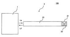
- FIG. 1is a side view diagram schematically indicating the configuration of a temperature sensor.
- Temperature sensor 100has a main unit 1 and a sensor probe 2 .
- the temperature sensor 100is a fluorescent type temperature sensor that measures temperature using a fluorescent substance in which the fluorescence characteristics change depending on temperature. Accordingly, a fluorescent material 21 that contains the fluorescent substance 25 is provided in the sensor probe 2 . Then, the sensor probe 2 is installed on the main unit 1 through a connector (not indicated in the diagram), etc.
- Provided on the main unit 1are: a light source, which emits the excitation light L e that is irradiated on the fluorescent material 21 ; a light detector, which detects the fluorescent light L f generated by the fluorescent substance contained in the fluorescent material 21 ; and a half mirror, etc. for separating the excitation light L e from the fluorescent light L f .
- the main unit 1is not limited to the configuration described above. The main unit 1 measures temperature by changes in the fluorescence lifetime when irradiated with pulse light.
- a yellow LED(light emitting diode) with a wavelength of approximately 600 nm is used for the light source.
- an easily obtainable LED with a core wavelength of 590 nmis used.
- excitation lightcan be stably irradiated on the fluorescent material 21 .
- a yellow LEDhas a long light source lifetime, the LED can operate for many hours.
- measurement noisecan be reduced.
- a photodiode made of siliconwhen irradiating with an excitation light having a short wavelength (for example, a wavelength of 405 nm), a current level is formed in the silicon chip.
- the sensor probe 2has fluorescent material 21 and guide wave route rod 23 .
- the fluorescent material 21is provided on the tip of the guide wave route rod 23 .
- the guide wave route rod 23has a long narrow rod shape.
- the guide wave route rod 23is of guide wave route material, for example, a quartz rod that propagates light or optical fibers. Further, bundled fibers in which multiple optical fibers are bundled together may be used. Consequently, the guide wave route rod 23 is configured by a transparent material with a high refractive index such as quartz or glass.
- the fluorescent light L fwhich is generated by the excitation light L e from this main unit 1 and the fluorescent material 21 , is propagated by being repeatedly and fully reflected within the guide wave route rod 23 .
- the guide wave route rod 23is a floodlight route for irradiating the fluorescent material 21 with the excitation light L e .
- the fluorescent material 21has a powder fluorescent substance 25 .
- the fluorescent material 21is composed of an aggregate of fluorescent substance powder.
- a protective tube to protect the guide wave route rod 23 and the fluorescent material 21may be provided.
- a powdersuch as ruby or alexandrite may be used as the fluorescent substance 25 .
- powdered rubyis used as the fluorescent substance 25 .
- the fluorescent material 21 that contains the fluorescent substance 25may be affixed to the tip of the guide wave route rod 23 using a binder or the like.
- the particle size of the powder fluorescent substance 25is 60 to 100 ⁇ m. Specifically, the particle size of the fluorescent substance 25 contained in the fluorescent material 21 is kept within the range of 60 to 100 ⁇ m. The intensity of fluorescence can thereby be heightened, and stable measurements become possible. Specifically, as indicated in FIG. 2 , when making the particle size larger than that in conventional technology, gaps are formed between individual particles 26 of the particles of fluorescent substance 25 .
- FIG. 2indicates an enlargement of the particles of fluorescent substance 25 in the fluorescent material.
- the solid linesindicate the propagation routes of the incident light, and the broken lines indicated the propagation routes of the fluorescent light.
- the individual particlesare indicated as spherical, but the actual powder has differing shapes with micro-contours.
- the excitation lightis diffused and reflected by Fresnel reflection at the surface boundary of the coating substance and the individual particles 26 of the fluorescent substance. Consequently, the excitation light can proceed deeply into the fluorescent material.
- the propagation distance of the excitation light into the fluorescent materialcan be extended, and the fluorescence intensity can be heightened.
- the fluorescence intensity in relation to noisecan be heightened in the detection circuit that is provided in the main unit 1 . Consequently, the signal noise ratio can be improved, and the calculated fluorescence lifetime is not easily affected by noise.
- the particle size uniform in a fixed rangethe inner stress of the powder can be made uniform. Because the inner stress of the powder is thereby made uniform, fluctuations of fluorescence lifetime can be reduced. It is thereby possible to make stable measurements.
- the interchangeability of sensor probescan thereby be heightened, and it is no longer necessary to calibrate for every sensor probe. Consequently, the costs of adjusting the temperature sensors can be lowered. Further, the powder use efficiency is heightened because powder in a broad particle size range of 60 to 100 ⁇ m can be used.
- the method of producing the fluorescent substance 25will be explained.
- ingotsare manufactured using a crystal growth method such as the Verneuil process.
- a monocrystal or polycrystal ruby crystal ingotis thereby formed.
- the concentration distributionis made uniform by agitating.
- Dependence on crystal orientationthereby disappears.
- the ruby powder particle sizeis made uniform in a fixed range.
- the ruby particlesare graded by size.
- the particle sizemay be determined by the weight method, mesh method, and laser particularity distribution measurement method.
- the mesh methodis used because the particles are easy to size. For example, each differing particle size can be graded depending on the size of the mesh.
- the powderis graded by size using a square mesh. For example, a mesh size of approximately 100 ⁇ m ⁇ 100 ⁇ m and a mesh size of approximately 60 ⁇ m ⁇ 60 ⁇ m are used. Then, the particle size range can be regulated by passing the pulverized particles through the 2 meshes. For example, powder with a particle size of 60 to 100 82 m can be separated out by passing through the 100- ⁇ m mesh followed by passing through the 60- ⁇ m mesh. Productivity can be improved by using meshes of different sizes in this way because grading can be simplified. The size of the powder can be made uniform by passing through 2 or more meshes, and the particle size can be confined to a fixed range. The fluorescence characteristics can thereby be stabilized. Further, measurement tests can be conducted by sizing the powder in the same way using a mesh size of approximately 80 ⁇ m ⁇ 80 ⁇ m and a mesh size of approximately 40 ⁇ m ⁇ 40 ⁇ m.
- FIGS. 3 to 6An example of the measurement results when varying the particle size range of the fluorescent substance 25 will be explained next using FIGS. 3 to 6 .
- the fluorescence lifetimewas measured using powdered ruby with a 0.2 mass % (wt %) Cr concentration. Specifically, 0.2 mass % chrome was contained in relation to alumina. Forty samples each of powdered ruby aggregate in fixed ranges of particle sizes were used. Then, all samples were used to measure the measurement target at room temperature, and fluctuations of fluorescence lifetime were investigated. Specifically, the standard deviations of the measured results of the 40 samples were taken as the fluctuations of fluorescence lifetime.
- FIGS. 3 and 4indicate the fluctuations of fluorescence lifetime when varying the particle size range.
- the fluctuations of fluorescence lifetime in relation to four types of sample particle rangesare indicated in FIGS. 3 and 4 .
- FIG. 3is the measured results of a group of samples having powdered ruby with particle size ranges descending from the upper limit value
- FIG. 4is the measured results of a group of samples having powdered ruby with particle size ranges ascending from the lower limit value and descending from the upper limit value.
- the results indicated in FIG. 3set only the upper limit value of particle size
- the results indicated in FIG. 4set the upper and lower limit values of particle size.
- the particle size ranges used in the measured results of FIG. 3be ranges A to D, and let the particle size ranges used in the measured results of FIG. 4 be ranges E to H.
- the measurement of range Ais the measurement of particle sizes less than 100 ⁇ m;
- the measurement of range Bis the measurement of particle sizes less than 80 ⁇ m;
- the measurement of range Cis the measurement of particle sizes less than 60 ⁇ m; and
- the measurement of range Dis the measurement of particle sizes less than 40 ⁇ m.
- the measurement of range Eis the measurement of particle sizes included in the range of 100 to 80 ⁇ m; the measurement of range F is the measurement of particle sizes included in the range of 80 to 60 ⁇ m; the measurement of range G is the measurement of particle sizes included in the range of 100 to 60 ⁇ m; and the measurement of range H is the measurement of particle sizes included in the range of 60 to 40 ⁇ m.
- range Gis a broader particle size range than ranges E and F, but the fluctuations of fluorescence lifetime are slightly smaller. Fluctuations of fluorescence lifetime can be suppressed in this way by making uniform particles of 60 ⁇ m or more and 100 ⁇ m or less.
- FIG. 5is a graph indicating the results of measuring ranges A to D
- FIG. 6is a graph indicating the results of measuring ranges E to H.
- the ordinateindicates the average value of the A/D converted values of the initial intensity of fluorescence. Consequently, the ordinate indicates the average value of the intensity of fluorescence in the 40 samples. In addition, the ordinate indicates the mean value of the intensity of fluorescence in the 40 samples. Moreover, the scales of the ordinate are equivalent in FIGS. 5 and 6 .
- the larger the particle sizethe higher the intensity of fluorescence.
- the excitation lightproceeds deeper because the gaps between adjacent particles are wider. Consequently, the propagation distance of the excitation light can become longer, and the intensity of fluorescence can be made higher.
- the intensity of fluorescence in the measurements of range Gis higher than in the measurements of range C. The intensity of fluorescence becomes higher by making the particle size uniform in this way.
- range Gis a broader particle size range than range F, but the intensity of fluorescence is nearly the same. Consequently, the efficiency of use of the powder fluorescent substance can be improved, and the productivity can be improved.
- the particle sizes of the fluorescent substance included in the fluorescent material 21are in the range of 100 to 60 ⁇ m. Gaps between the particles 26 of fluorescent substance 25 can thereby be made, and the propagation distance of the excitation light becomes longer. Consequently, the excitation light proceeds more deeply into the fluorescent material 21 . The intensity of fluorescence can thereby become higher and stable measurements become possible. Stable measurements become possible by using an aggregate of fluorescent particles with a particle size of 60 to 100 ⁇ m.
- the amount of Cr added to aluminamay be other than 0.2 mass % (wt %).
- the present inventionis not limited to powdered ruby fluorescent substance, and powdered alexandrite fluorescent substance may also be used.
- the wavelength of the excitation lightmay be varied from yellow (central wavelength 590 nm). For example, if the wavelength is smaller, the refractive index is greater and the light bends well, but the aforementioned range of particle sizes hardly changes. Measurements can thereby be stabilized even if there are differences in the wavelengths of the excitation light.
Landscapes
- Physics & Mathematics (AREA)
- General Physics & Mathematics (AREA)
- Investigating, Analyzing Materials By Fluorescence Or Luminescence (AREA)
- Measuring Temperature Or Quantity Of Heat (AREA)
Abstract
Description
Claims (4)
Applications Claiming Priority (2)
| Application Number | Priority Date | Filing Date | Title |
|---|---|---|---|
| JP2007302587AJP5001119B2 (en) | 2007-11-22 | 2007-11-22 | Temperature sensor probe and manufacturing method thereof |
| JP2007-302587 | 2007-11-22 |
Publications (2)
| Publication Number | Publication Date |
|---|---|
| US20090135881A1 US20090135881A1 (en) | 2009-05-28 |
| US8157441B2true US8157441B2 (en) | 2012-04-17 |
Family
ID=40669664
Family Applications (1)
| Application Number | Title | Priority Date | Filing Date |
|---|---|---|---|
| US12/274,480Expired - Fee RelatedUS8157441B2 (en) | 2007-11-22 | 2008-11-20 | Temperature sensor probe |
Country Status (5)
| Country | Link |
|---|---|
| US (1) | US8157441B2 (en) |
| JP (1) | JP5001119B2 (en) |
| KR (1) | KR100986780B1 (en) |
| CN (1) | CN101441117B (en) |
| TW (1) | TWI390190B (en) |
Cited By (1)
| Publication number | Priority date | Publication date | Assignee | Title |
|---|---|---|---|---|
| US20080144698A1 (en)* | 2006-12-19 | 2008-06-19 | Mathieu Cloutier | Fiber optic temperature sensor |
Families Citing this family (9)
| Publication number | Priority date | Publication date | Assignee | Title |
|---|---|---|---|---|
| JP5064183B2 (en)* | 2007-11-22 | 2012-10-31 | アズビル株式会社 | Manufacturing method of temperature sensor probe |
| JP5299812B2 (en)* | 2008-03-31 | 2013-09-25 | アズビル株式会社 | Fluorescent temperature sensor |
| JP5225752B2 (en)* | 2008-05-27 | 2013-07-03 | アズビル株式会社 | Fluorescence temperature sensor |
| WO2011127593A1 (en) | 2010-04-17 | 2011-10-20 | Powell Canada Inc. | Photoluminescent temperature sensor utilizing a singular element for excitation and photodetection |
| JP6336713B2 (en)* | 2013-05-17 | 2018-06-06 | アジアメディカルセンター,プライベート リミテッド | Method of operating apparatus equipped with optical fiber for visualizing biological tissue information |
| US10222274B2 (en)* | 2016-09-28 | 2019-03-05 | General Electric Company | Thermographic temperature sensor |
| EP3492909B1 (en) | 2017-12-01 | 2023-11-01 | ams AG | Chemical sensing device using fluorescent sensing material |
| EP3931537A4 (en)* | 2019-03-01 | 2023-02-22 | Daryl James | Fluorescence time decay sensing apparatus and methods of manufacturing same |
| US20200393308A1 (en)* | 2019-06-14 | 2020-12-17 | Photon Control Inc. | Fiber Optic Temperature Probe |
Citations (20)
| Publication number | Priority date | Publication date | Assignee | Title |
|---|---|---|---|---|
| US498212A (en)* | 1893-05-23 | Needle-clamp carrier for sewing-machines | ||
| US4776827A (en)* | 1986-09-01 | 1988-10-11 | The General Electric Company P.L.C. | Temperature sensing system using a phosphor having a temperature-dependent luminescent decay time |
| US4789992A (en)* | 1985-10-15 | 1988-12-06 | Luxtron Corporation | Optical temperature measurement techniques |
| US4895156A (en)* | 1986-07-02 | 1990-01-23 | Schulze John E | Sensor system using fluorometric decay measurements |
| JPH02290518A (en) | 1989-01-24 | 1990-11-30 | Degussa Ag | Temperature measuring method using fluorescent material and manufacturing method of fluorescent material |
| US5030834A (en)* | 1987-12-01 | 1991-07-09 | Quantex Corporation | Fiber optic dosimeter system using electron trapping materials |
| US5051590A (en)* | 1989-12-06 | 1991-09-24 | Santa Barbara Research Center | Fiber optic flame detection and temperature measurement system having one or more in-line temperature dependent optical filters |
| JPH04357420A (en)* | 1991-05-20 | 1992-12-10 | Nippon Telegr & Teleph Corp <Ntt> | Infrared light detection element |
| US5211480A (en)* | 1990-10-18 | 1993-05-18 | Rosemount Inc. | TRD temperature sensor and electronics |
| US5255980A (en)* | 1990-10-18 | 1993-10-26 | Rosemount Inc. | Black body TRD temperature sensor |
| US5351268A (en)* | 1990-12-04 | 1994-09-27 | Luxtron Corporation | Modular luminescence-based measuring system using fast digital signal processing |
| US5355423A (en)* | 1992-07-16 | 1994-10-11 | Rosemount Inc. | Optical temperature probe assembly |
| US6045259A (en)* | 1996-10-04 | 2000-04-04 | University Of South Florida | Fiber-optic high temperature sensor |
| US6123455A (en)* | 1997-05-02 | 2000-09-26 | American Iron And Steel Institute | Phosphor thermometry system |
| JP2002071473A (en) | 2000-09-04 | 2002-03-08 | Anritsu Keiki Kk | Fluorescent optical fiber thermometer |
| US6571482B1 (en)* | 1998-07-10 | 2003-06-03 | Nanoptics, Inc. | Sighting device for projectile type weapons for operation in day and night |
| US20050109951A1 (en)* | 2001-12-27 | 2005-05-26 | Falk Fish | Novel device, system and method for fluorescence detection |
| US20070228949A1 (en) | 2006-03-31 | 2007-10-04 | Dowa Electronics Materials Co., Ltd. | Light emitting device and method for producing same |
| US20080069180A1 (en)* | 2006-09-19 | 2008-03-20 | Derek Djeu | Fiber optic temperature sensing system using a hemispherical phosphor |
| US20090135880A1 (en)* | 2007-11-22 | 2009-05-28 | Yamatake Corporation | Temperature sensor probe and manufacturing method of the same |
Family Cites Families (4)
| Publication number | Priority date | Publication date | Assignee | Title |
|---|---|---|---|---|
| JPS62298734A (en) | 1986-06-18 | 1987-12-25 | Omron Tateisi Electronics Co | Fluorescent type optical fiber probe |
| DE19548922A1 (en) | 1995-12-27 | 1997-07-03 | Max Planck Gesellschaft | Optical temperature sensors and optrodes with optical temperature compensation |
| KR100376277B1 (en)* | 2000-08-22 | 2003-03-17 | 한국화학연구원 | Process for Preparing (YxGd1-x)2O3:Eu Phosphor Particles with monoclinic and cubic phases by Flame Spray Pyrolysis |
| JP2002340698A (en)* | 2001-05-11 | 2002-11-27 | Ohkura Electric Co Ltd | Integrating sphere type optical fiber thermometer |
- 2007
- 2007-11-22JPJP2007302587Apatent/JP5001119B2/ennot_activeExpired - Fee Related
- 2008
- 2008-10-27TWTW097141185Apatent/TWI390190B/ennot_activeIP Right Cessation
- 2008-10-30KRKR1020080107082Apatent/KR100986780B1/ennot_activeExpired - Fee Related
- 2008-11-19CNCN2008101770395Apatent/CN101441117B/ennot_activeExpired - Fee Related
- 2008-11-20USUS12/274,480patent/US8157441B2/ennot_activeExpired - Fee Related
Patent Citations (21)
| Publication number | Priority date | Publication date | Assignee | Title |
|---|---|---|---|---|
| US498212A (en)* | 1893-05-23 | Needle-clamp carrier for sewing-machines | ||
| US4789992A (en)* | 1985-10-15 | 1988-12-06 | Luxtron Corporation | Optical temperature measurement techniques |
| US4895156A (en)* | 1986-07-02 | 1990-01-23 | Schulze John E | Sensor system using fluorometric decay measurements |
| US4776827A (en)* | 1986-09-01 | 1988-10-11 | The General Electric Company P.L.C. | Temperature sensing system using a phosphor having a temperature-dependent luminescent decay time |
| US5030834A (en)* | 1987-12-01 | 1991-07-09 | Quantex Corporation | Fiber optic dosimeter system using electron trapping materials |
| JPH02290518A (en) | 1989-01-24 | 1990-11-30 | Degussa Ag | Temperature measuring method using fluorescent material and manufacturing method of fluorescent material |
| US5035513A (en)* | 1989-01-24 | 1991-07-30 | Degussa Ag | Fluorescent material temperature sensor |
| US5051590A (en)* | 1989-12-06 | 1991-09-24 | Santa Barbara Research Center | Fiber optic flame detection and temperature measurement system having one or more in-line temperature dependent optical filters |
| US5255980A (en)* | 1990-10-18 | 1993-10-26 | Rosemount Inc. | Black body TRD temperature sensor |
| US5211480A (en)* | 1990-10-18 | 1993-05-18 | Rosemount Inc. | TRD temperature sensor and electronics |
| US5351268A (en)* | 1990-12-04 | 1994-09-27 | Luxtron Corporation | Modular luminescence-based measuring system using fast digital signal processing |
| JPH04357420A (en)* | 1991-05-20 | 1992-12-10 | Nippon Telegr & Teleph Corp <Ntt> | Infrared light detection element |
| US5355423A (en)* | 1992-07-16 | 1994-10-11 | Rosemount Inc. | Optical temperature probe assembly |
| US6045259A (en)* | 1996-10-04 | 2000-04-04 | University Of South Florida | Fiber-optic high temperature sensor |
| US6123455A (en)* | 1997-05-02 | 2000-09-26 | American Iron And Steel Institute | Phosphor thermometry system |
| US6571482B1 (en)* | 1998-07-10 | 2003-06-03 | Nanoptics, Inc. | Sighting device for projectile type weapons for operation in day and night |
| JP2002071473A (en) | 2000-09-04 | 2002-03-08 | Anritsu Keiki Kk | Fluorescent optical fiber thermometer |
| US20050109951A1 (en)* | 2001-12-27 | 2005-05-26 | Falk Fish | Novel device, system and method for fluorescence detection |
| US20070228949A1 (en) | 2006-03-31 | 2007-10-04 | Dowa Electronics Materials Co., Ltd. | Light emitting device and method for producing same |
| US20080069180A1 (en)* | 2006-09-19 | 2008-03-20 | Derek Djeu | Fiber optic temperature sensing system using a hemispherical phosphor |
| US20090135880A1 (en)* | 2007-11-22 | 2009-05-28 | Yamatake Corporation | Temperature sensor probe and manufacturing method of the same |
Cited By (2)
| Publication number | Priority date | Publication date | Assignee | Title |
|---|---|---|---|---|
| US20080144698A1 (en)* | 2006-12-19 | 2008-06-19 | Mathieu Cloutier | Fiber optic temperature sensor |
| US8277119B2 (en)* | 2006-12-19 | 2012-10-02 | Vibrosystm, Inc. | Fiber optic temperature sensor |
Also Published As
| Publication number | Publication date |
|---|---|
| TWI390190B (en) | 2013-03-21 |
| JP2009128145A (en) | 2009-06-11 |
| KR20090053686A (en) | 2009-05-27 |
| US20090135881A1 (en) | 2009-05-28 |
| TW200925568A (en) | 2009-06-16 |
| CN101441117B (en) | 2011-02-09 |
| CN101441117A (en) | 2009-05-27 |
| JP5001119B2 (en) | 2012-08-15 |
| KR100986780B1 (en) | 2010-10-12 |
Similar Documents
| Publication | Publication Date | Title |
|---|---|---|
| US8157441B2 (en) | Temperature sensor probe | |
| US7507022B2 (en) | Apparatus for measuring temperature using luminescence thermometry | |
| US8709592B2 (en) | Sensor coating | |
| Negre et al. | On the performance of laser-induced breakdown spectroscopy for quantitative analysis of minor and trace elements in glass | |
| CN102680429B (en) | Subminiature microcavity gas sensor | |
| EP3492909B1 (en) | Chemical sensing device using fluorescent sensing material | |
| US20110301066A1 (en) | Adhesion layer enhancement of plasmonic fluorescence | |
| CN1971267B (en) | Waveguide coupling surface plasma resonance biosensor | |
| JP2015232522A (en) | Optical fiber sensor device | |
| CN105403536A (en) | Nanowire-based liquid refractive index probe and detection system and detecting method thereof | |
| US20190154577A1 (en) | Atr-spectrometer | |
| US9464986B2 (en) | Multiplex fiber optic biosensor and detection method by using the same | |
| US7554093B1 (en) | Uniformly responsive ultraviolet sensors | |
| US6404489B1 (en) | Inclusion detection | |
| CN108489631B (en) | Absorption spectrum intensity ratio temperature measurement method | |
| JP2006105599A (en) | Temperature measuring method, temperature stress measuring method, high-temperature stress time measuring method, temperature measuring instrument, temperature stress measuring instrument, and high-temperature stress time measuring instrument | |
| Weigel et al. | Whispering gallery mode pressure sensing | |
| CN101910827A (en) | Microelectronic sensor device | |
| Bidin et al. | Determination of hydrocarbon level in distilled water via fiber optic displacement sensor | |
| EP4332557B1 (en) | A system for optical inspection of a substrate using same or different wavelengths | |
| RU131183U1 (en) | ON-BOARD FUEL QUALITY ASSESSMENT DEVICE | |
| Osipov et al. | A setup for measuring the refractive index of a plane-parallel ceramic plate using the optical beam shift method | |
| Rahmani et al. | Near-field optical probing of fluorescent microspheres using a photon scanning tunneling microscope | |
| JP2015175780A (en) | sensor device and measurement method | |
| Saarela et al. | Three methods for photon migration measurements in pulp |
Legal Events
| Date | Code | Title | Description |
|---|---|---|---|
| AS | Assignment | Owner name:YAMATAKE CORPORATION, JAPAN Free format text:ASSIGNMENT OF ASSIGNORS INTEREST;ASSIGNORS:KINUGASA, SEIICHIRO;KATO, ATSUSHI;REEL/FRAME:021866/0933 Effective date:20081024 | |
| STCF | Information on status: patent grant | Free format text:PATENTED CASE | |
| FEPP | Fee payment procedure | Free format text:PAYOR NUMBER ASSIGNED (ORIGINAL EVENT CODE: ASPN); ENTITY STATUS OF PATENT OWNER: LARGE ENTITY | |
| FPAY | Fee payment | Year of fee payment:4 | |
| AS | Assignment | Owner name:AZBIL CORPORATION, JAPAN Free format text:CHANGE OF NAME;ASSIGNOR:YAMATAKE CORPORATION;REEL/FRAME:043906/0231 Effective date:20120402 | |
| FEPP | Fee payment procedure | Free format text:MAINTENANCE FEE REMINDER MAILED (ORIGINAL EVENT CODE: REM.); ENTITY STATUS OF PATENT OWNER: LARGE ENTITY | |
| LAPS | Lapse for failure to pay maintenance fees | Free format text:PATENT EXPIRED FOR FAILURE TO PAY MAINTENANCE FEES (ORIGINAL EVENT CODE: EXP.); ENTITY STATUS OF PATENT OWNER: LARGE ENTITY | |
| STCH | Information on status: patent discontinuation | Free format text:PATENT EXPIRED DUE TO NONPAYMENT OF MAINTENANCE FEES UNDER 37 CFR 1.362 | |
| FP | Lapsed due to failure to pay maintenance fee | Effective date:20200417 |