US8157109B2 - Mountable storage apparatus with retractable linking mechanism and method - Google Patents
Mountable storage apparatus with retractable linking mechanism and methodDownload PDFInfo
- Publication number
- US8157109B2 US8157109B2US11/955,173US95517307AUS8157109B2US 8157109 B2US8157109 B2US 8157109B2US 95517307 AUS95517307 AUS 95517307AUS 8157109 B2US8157109 B2US 8157109B2
- Authority
- US
- United States
- Prior art keywords
- receptacle
- connector
- storage apparatus
- mountable storage
- wall
- Prior art date
- Legal status (The legal status is an assumption and is not a legal conclusion. Google has not performed a legal analysis and makes no representation as to the accuracy of the status listed.)
- Expired - Fee Related, expires
Links
- 238000000034methodMethods0.000titleabstractdescription8
- 238000002372labellingMethods0.000claims1
- 239000000725suspensionSubstances0.000abstractdescription2
- 238000010276constructionMethods0.000description1
- 239000000463materialSubstances0.000description1
- 230000013011matingEffects0.000description1
- 239000002184metalSubstances0.000description1
- 239000002991molded plasticSubstances0.000description1
- 238000004806packaging method and processMethods0.000description1
- 230000002787reinforcementEffects0.000description1
- 239000012858resilient materialSubstances0.000description1
- 239000000758substrateSubstances0.000description1
Images


Classifications
- A—HUMAN NECESSITIES
- A47—FURNITURE; DOMESTIC ARTICLES OR APPLIANCES; COFFEE MILLS; SPICE MILLS; SUCTION CLEANERS IN GENERAL
- A47F—SPECIAL FURNITURE, FITTINGS, OR ACCESSORIES FOR SHOPS, STOREHOUSES, BARS, RESTAURANTS OR THE LIKE; PAYING COUNTERS
- A47F7/00—Show stands, hangers, or shelves, adapted for particular articles or materials
- A47F7/14—Show stands, hangers, or shelves, adapted for particular articles or materials for pictures, e.g. in combination with books or seed-bags ; for cards, magazines, newspapers, books or booklike articles, e.g. audio/video cassettes
- A47F7/146—Show stands, hangers, or shelves, adapted for particular articles or materials for pictures, e.g. in combination with books or seed-bags ; for cards, magazines, newspapers, books or booklike articles, e.g. audio/video cassettes the show stands or the like being provided with compartments or pockets
- A—HUMAN NECESSITIES
- A47—FURNITURE; DOMESTIC ARTICLES OR APPLIANCES; COFFEE MILLS; SPICE MILLS; SUCTION CLEANERS IN GENERAL
- A47B—TABLES; DESKS; OFFICE FURNITURE; CABINETS; DRAWERS; GENERAL DETAILS OF FURNITURE
- A47B43/00—Cabinets, racks or shelf units, characterised by features enabling folding of the cabinet or the like
- A47B43/003—Suspended shelves, e.g. by means of supple elements
Definitions
- the present inventive conceptrelates generally to an apparatus and method of organizing documents and other tangible items, and more particularly, to an apparatus and a method comprising a wall-mounted receptacle capable of supporting additional receptacles thereon.
- the present inventionrelates to a novel apparatus and method for organizing, storing or filing items including, for example, a substrate, office supplies and/or other tangible articles in one or more hanging receptacles or the like.
- the apparatuscomprises a primary receptacle which may be mounted, for example, to a surface such as the wall of a room, cubicle, or the like.
- the primary receptaclemay then accommodate or support one or more additional receptacles via attachment to and suspension from a attachment mechanism (e.g., a hook) that is pivotally attached to a bottom of the primary receptacle. Additional receptacles may then be successively attached in series or parallel in like fashion.
- a attachment mechanisme.g., a hook
- a primary object of the present general inventive conceptis to provide a filing apparatus having a primary receptacle that may easily accept additional units depending on a desired application of the filing apparatus, thereby increasing versatility.
- the retractable attachment mechanismallows adaptability and flexibility for use of the apparatus in a variety of spaces also provides aesthetically pleasing appearance, increased safety, and ease and efficiency for packaging, and shipping and storing the apparatus.
- a principal object of the present general inventive conceptis to provide a method and system to organize items in one or more receptacles situated on a wall so that files therein may be easily indentified without requiring manual manipulation of the files.
- Another object of the present general inventive conceptis to provide a method and system to organize files in a first receptacle unit that supports additional receptacle units each arranged successivly and depending one from another.
- Another object of the present general inventive conceptto provide a method and system to organize files, the system having a first receptacle unit to support additional receptacle units so that only the first receptacle requires securing to a wall.
- Another another object of the present general inventive conceptto provide a simple low-cost system to organize files and/or individual papers and for separating such files and/or papers into defined areas for easy identification and removal.
- Another another object of the present general inventive conceptto provide a system to organize files having a number of receptacles that are efficiently designed with a front side, left and right sides, and a partial rear side that is supplemented in part by the wall.
- Another another object of the present general inventive conceptto provide a system to organize files having a number of units each having a receptacle that is efficiently designed with a front side, left and right sides, and a partial rear side that is supplemented in part by the wall to form the receptacle.
- Another another object of the present general inventive conceptto provide a system to organize files having a number of units with each unit being identical and self-contained so that each unit may hang from or be hung from each other.
- FIG. 1is a perspective view of the filing system of the present general inventive concept illustrated in FIG. 1 .
- FIG. 2is a rear perspective view of a single receptacle of the filing system of the present general inventive concept.
- FIG. 3is a front view of a hook of the present general inventive concept.
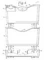
- FIG. 4is a front view of a mountable storage apparatus of the present general inventive concept illustrating an upper primary receptacle with a second identical receptacle attached to the primary receptacle, and an organizer receptacle attached to the second receptacle.
- FIG. 5is a side view of the filing system of the present general inventive concept illustrated in FIG. 1 .
- FIG. 6is a rear view of the filing system of the present general inventive concept illustrated in FIG. 1 with a rear opening to abut a wall.
- FIG. 7is a top view of the filing system of the present general inventive concept illustrating an upper primary receptacle with an interior.
- FIG. 8is an illustration of the present general inventive concept showing an enlarged fragmentary view of an attachment hook thereof.
- the present general inventive conceptincludes a wall-mounted filing system 1 .
- the filing system 1is configured with a primary wall receptacle 3 having a generally rectangular shape.
- the wall receptacle 3includes an upper lip 10 to support, for example, a business card holder 15 to hold standard business cards and/or other like-shaped objects.
- the business card holder 15may be attached to the upper lip 10 via a hook 17 molded into a back of the business card holder 15 .
- a label holder 16may also be attached to the upper lip 10 via a hook 18 molded into a back of the label holder 16 so that a user may indicate a type of use for the wall receptacle 3 , e.g., if the wall receptacle 3 is used as a mailbox, a name can be assigned via the label holder 16 .
- the label holder 16is oval and manufactured via two pieces of molded plastic with an opening that is approximately 1 ⁇ 8′′ slot located at the top of the holder 16 to receive and hold a piece of paper to allow the user to label the receptacle 3 . Any depending wall receptacle 3 may have its own business card holder 15 and label holder 16 .
- Attached to either side of a lower end 5 of the primary wall receptacle 3are two generally u-shaped hooks 4 having an open end 7 and a closed end 8 .
- the open end 7has laterally-extending points 9 that are sized and shaped to engage apertures 12 and permit rotation of the hook 4 upon engagement of the hook 4 with the receptacle 3 .
- the apertures 12are located in either side of a groove 19 that extends from the lower end 5 of the wall receptacle 3 to the upper lip 10 .
- the u-shaped hooks 4once engaged within the apertures 12 , may be selectively rotated up and down between an extended position (illustrated in FIG. 1 ) and a retracted position (illustrated in FIG. 15 ).
- the u-shaped hooks 4When rotated downward to the extended position, the u-shaped hooks 4 are configured to receive a mating tab 25 from an additional receptacle 30 such that each of the hooks 4 that extend from the primary receptacle 3 provides support or a mounting attachment for the tab 25 of the additional receptacle 30 .
- the u-shaped hook 4When rotated upward to the retracted position, the u-shaped hook 4 is in a collapsed or storage configuration, such that the hook 4 is effectively hidden behind the receptacle 3 .
- the u-shaped hooks 4are made of a resilient material such as metal and have bends 22 in arms 23 to provide structural reinforcement of the u-shaped hooks and a degree of resiliency.
- the u-shaped hooks 4engage the apertures 12 by pinching or compressing the hooks 4 at the arms 23 , aligning the hook points 9 with the apertures 12 , and releasing the hooks 4 so that the points 9 resiliently spring back or decompress to their original position, thereby entering the apertures 12 .
- Each groove 19has four square projections 20 that extend out from a rear wall 21 of the groove 21 .
- the projections 20are arranged in two rows, an upper row and a lower row, each having two of the projections 20 .
- the upper rowis located slightly above the apertures 12 while the lower row is located slightly below the apertures 12 .
- the projections 20block and otherwise restrict flexing of the u-shaped hooks 4 when the u-shaped hooks 4 are in the storage or use configuration so as to prevent undesired disengagement of the hooks 4 with the apertures 12 .
- the projections 20permit flexing of the u-shaped hooks 4 only when the hooks 4 are rotated to a position that is precisely between the storage and use configuration (not illustrated) so that the u-shaped hooks 4 extend in a direction parallel to the projection direction of the projections 20 project out from the rear wall 21 .
- the u-shaped hooks 4When the u-shaped hooks 4 are in the storage configuration, the u-shaped hooks rest inside the groove 19 so that a rear surface 6 of the wall receptacle 3 is generally flush to provide a planar rear surface 6 and thereby facilitate secure mounting of the wall receptacle 3 to a wall (not illustrated).
- each primary receptacle 3 and additional receptacle 30are identically shaped and have a mounting tab 25 located in each groove 19 that is sized and shaped to receive the closed end 8 of the hook 4 .
- the tab 25extends outward from the rear of the wall receptacle 3 and has a downwardly-protruding point to partially surround and securely engage the closed end 8 of the hook 4 .
- the tab 25is entirely contained within the groove 19 and is flush with the rear surface 6 of the wall receptacle 3 to provide a planar rear surface 6 and thereby facilitate secure mounting of the wall receptacle 3 to the wall.
- any number of additional receptacles 30may be sequentially attached to each other with the primary limiting factors being space available on the wall and reach of the user required to gain access to the receptacles 3 and 30 .
- the primary receptacle 3is mounted to the wall, an additional receptacle 30 is attached to the first wall receptacle 3 via hooks 4 , and an organizer 40 is attached to the second wall receptacle 3 via hooks 4 .
- the additional receptacles 33are interchangeable with the organizer 40 and may be arranged in any order depending on application, such as with the organizer 40 as the primary wall mount and the primary receptacle 3 depending therefrom.
- the organizer 40is designed exactly the same as the receptacles 3 and 30 , having hooks 4 in grooves 19 with mounting tabs 25 and having the same width as the receptacles 3 and 30 , but the organizer 40 is approximately one-third as deep as the receptacles 3 and 30 .
- the organizer 40has four removable dividers 41 within an interior thereof, however, it is foreseen that any number of dividers can be used depending on application.
- the dividers 41are easily installed via the user by sliding each divider 40 between laterally extending grooves 42 located on an interior of the front and rear surfaces.
- the dividers 41have a bottom surface with via two tabs 43 that extend downward and into two tab-receiver apertures 44 in the organizer 40 bottom surface to further secure the dividers 40 .
- the primary receptacle 3is first mounted to the wall, however, the organizer 40 may also be first mounted.
- the organizer 40On either side of an upper portion of the groove 19 in the rear wall of both the wall receptacle 3 and organizer 40 are upper apertures 49 .
- tabs 48On the lower portion of the groove are tabs 48 having lower apertures 50 .
- the apertures 49 and 50may be used to mount the wall receptacle 3 and/or the organizer 40 to the wall via screws, nails, or the like.
- the hooks 4must be moved to either the use configuration or the storage configuration prior to using the lower apertures 50 . After the lower apertures 50 are used to secure the wall receptacles 3 or 30 , and/or organizer 40 to the wall, the hooks 4 cannot thereafter be rotated.
- the wall receptacles 3 and 30 , and/or the organizer 40have a dip 53 in the upper lip 10 to permit easy access to any contents stored therein.
- the wall receptacles 3 and 30have an opening 55 in the rear wall 6 , which requires less material and provides a system 1 with increased efficiency. Because the receptacles 3 and 30 abut a wall (not illustrated), which provides a rear surface, the wall receptacles 3 and 30 can be designed with only a partial rear wall 6 .
- the wall receptacles 3 and 30 , and/or the organizer 40may be manufactured in various shapes depending on application to accommodate various items
- hooks 4that rotate on a horizontal axis and in two directions, i.e., up and down
- hooksmay rotate on a vertical axis and from left to right to provide increased versatility in mounting of add-ons.
- receptaclesmay extend horizontally or horizontally and vertically along a wall.
- hooks or other like attachment meansmay be situated on one side or both sides of a primary receptacle to support additional receptacles on either side of the primary receptacle.
- the additional receptaclesmay also support further additional receptacles.
Landscapes
- Supports Or Holders For Household Use (AREA)
- Sheet Holders (AREA)
Abstract
Description
Claims (10)
Priority Applications (1)
| Application Number | Priority Date | Filing Date | Title |
|---|---|---|---|
| US11/955,173US8157109B2 (en) | 2007-12-12 | 2007-12-12 | Mountable storage apparatus with retractable linking mechanism and method |
Applications Claiming Priority (1)
| Application Number | Priority Date | Filing Date | Title |
|---|---|---|---|
| US11/955,173US8157109B2 (en) | 2007-12-12 | 2007-12-12 | Mountable storage apparatus with retractable linking mechanism and method |
Publications (2)
| Publication Number | Publication Date |
|---|---|
| US20100038330A1 US20100038330A1 (en) | 2010-02-18 |
| US8157109B2true US8157109B2 (en) | 2012-04-17 |
Family
ID=41680561
Family Applications (1)
| Application Number | Title | Priority Date | Filing Date |
|---|---|---|---|
| US11/955,173Expired - Fee RelatedUS8157109B2 (en) | 2007-12-12 | 2007-12-12 | Mountable storage apparatus with retractable linking mechanism and method |
Country Status (1)
| Country | Link |
|---|---|
| US (1) | US8157109B2 (en) |
Cited By (3)
| Publication number | Priority date | Publication date | Assignee | Title |
|---|---|---|---|---|
| USD710443S1 (en)* | 2013-12-03 | 2014-08-05 | Block And Company, Inc. | Holder |
| US20150173529A1 (en)* | 2013-12-23 | 2015-06-25 | Wal-Mart Stores, Inc. | Modular shelf assembly for a cosmetic fixture system |
| US20150289618A1 (en)* | 2014-04-15 | 2015-10-15 | Finder Enterprises, Llc | Personal items retrieval system |
Families Citing this family (7)
| Publication number | Priority date | Publication date | Assignee | Title |
|---|---|---|---|---|
| CA2818721A1 (en)* | 2010-11-22 | 2012-05-31 | Plastics Tooling And Marketing Pty Ltd | Adjustable display apparatus |
| US8878673B2 (en) | 2011-05-19 | 2014-11-04 | Invue Security Products Inc. | Systems and methods for protecting retail display merchandise from theft |
| US9206827B2 (en) | 2012-11-20 | 2015-12-08 | Avery Dennison Corporation | Wall mount organization system |
| JP5565513B1 (en)* | 2013-01-08 | 2014-08-06 | 日本電気株式会社 | Coordinate transformation device, coordinate transformation program, and coordinate transformation method |
| US20140284293A1 (en)* | 2013-03-19 | 2014-09-25 | Ginsey Industries, Inc. | Shower Storage Caddy |
| US9033161B2 (en)* | 2013-09-05 | 2015-05-19 | Target Brands, Inc. | Wall organizer |
| US11147404B1 (en)* | 2020-08-18 | 2021-10-19 | James Duffy | Garment organizer assembly |
Citations (20)
| Publication number | Priority date | Publication date | Assignee | Title |
|---|---|---|---|---|
| US2112925A (en)* | 1936-03-27 | 1938-04-05 | Stromberg Electric Company | Card rack |
| US3234616A (en)* | 1965-02-16 | 1966-02-15 | Edward F Wantland | Ring fasteners |
| US4083456A (en)* | 1976-03-01 | 1978-04-11 | Controlled Sheet Music Service, Inc. | Terraced modular rack assembly |
| US4162014A (en)* | 1977-05-16 | 1979-07-24 | Eldon Industries, Inc. | Vertical file construction |
| US4613047A (en)* | 1985-03-25 | 1986-09-23 | Hallmark Cards, Incorporated | Small article display assembly |
| US4696081A (en)* | 1987-01-06 | 1987-09-29 | Yen Down W | Clip resiliant |
| US5009335A (en)* | 1988-05-02 | 1991-04-23 | Jonker Robert G C | Display device for flat articles |
| US5184737A (en)* | 1991-06-21 | 1993-02-09 | American Greetings Corporation | Display system having suspended channels and method of assembly |
| US5222609A (en)* | 1990-08-08 | 1993-06-29 | Eaton Peter R K | Display apparatus |
| US5344030A (en)* | 1993-08-11 | 1994-09-06 | Rubbermaid Office Products Group, Inc. | Expandable modular wall file with hidden attachment and support means |
| US5823359A (en)* | 1996-05-30 | 1998-10-20 | Sterling Plastics Co. | Desktop vertical file assembly |
| US6016926A (en)* | 1997-11-25 | 2000-01-25 | Summer Infant Products, Inc. | Infant bath toy mounting device |
| US6092672A (en)* | 1996-05-30 | 2000-07-25 | Berol Corporation | Desktop modular assembly |
| US6226840B1 (en)* | 1999-08-05 | 2001-05-08 | Wann-Pao Lu | Structure binder clip |
| US20020030028A1 (en)* | 1997-02-13 | 2002-03-14 | Robert Isserstedt | Storage device |
| US6412648B1 (en)* | 1999-06-25 | 2002-07-02 | Eml Limited | Display apparatus |
| US6422403B1 (en)* | 2000-03-03 | 2002-07-23 | Eml Limited | Display apparatus |
| US20060016772A1 (en)* | 2004-07-22 | 2006-01-26 | Design Research & Development Corporation | Tool and gear organizer system with secure hanging method |
| US7712641B2 (en)* | 2007-09-26 | 2010-05-11 | Paula Ann Snyder | System and method for hanging garments |
| US7730593B1 (en)* | 2004-09-28 | 2010-06-08 | Juilly Brett A | Binder clip with label holder |
- 2007
- 2007-12-12USUS11/955,173patent/US8157109B2/ennot_activeExpired - Fee Related
Patent Citations (20)
| Publication number | Priority date | Publication date | Assignee | Title |
|---|---|---|---|---|
| US2112925A (en)* | 1936-03-27 | 1938-04-05 | Stromberg Electric Company | Card rack |
| US3234616A (en)* | 1965-02-16 | 1966-02-15 | Edward F Wantland | Ring fasteners |
| US4083456A (en)* | 1976-03-01 | 1978-04-11 | Controlled Sheet Music Service, Inc. | Terraced modular rack assembly |
| US4162014A (en)* | 1977-05-16 | 1979-07-24 | Eldon Industries, Inc. | Vertical file construction |
| US4613047A (en)* | 1985-03-25 | 1986-09-23 | Hallmark Cards, Incorporated | Small article display assembly |
| US4696081A (en)* | 1987-01-06 | 1987-09-29 | Yen Down W | Clip resiliant |
| US5009335A (en)* | 1988-05-02 | 1991-04-23 | Jonker Robert G C | Display device for flat articles |
| US5222609A (en)* | 1990-08-08 | 1993-06-29 | Eaton Peter R K | Display apparatus |
| US5184737A (en)* | 1991-06-21 | 1993-02-09 | American Greetings Corporation | Display system having suspended channels and method of assembly |
| US5344030A (en)* | 1993-08-11 | 1994-09-06 | Rubbermaid Office Products Group, Inc. | Expandable modular wall file with hidden attachment and support means |
| US5823359A (en)* | 1996-05-30 | 1998-10-20 | Sterling Plastics Co. | Desktop vertical file assembly |
| US6092672A (en)* | 1996-05-30 | 2000-07-25 | Berol Corporation | Desktop modular assembly |
| US20020030028A1 (en)* | 1997-02-13 | 2002-03-14 | Robert Isserstedt | Storage device |
| US6016926A (en)* | 1997-11-25 | 2000-01-25 | Summer Infant Products, Inc. | Infant bath toy mounting device |
| US6412648B1 (en)* | 1999-06-25 | 2002-07-02 | Eml Limited | Display apparatus |
| US6226840B1 (en)* | 1999-08-05 | 2001-05-08 | Wann-Pao Lu | Structure binder clip |
| US6422403B1 (en)* | 2000-03-03 | 2002-07-23 | Eml Limited | Display apparatus |
| US20060016772A1 (en)* | 2004-07-22 | 2006-01-26 | Design Research & Development Corporation | Tool and gear organizer system with secure hanging method |
| US7730593B1 (en)* | 2004-09-28 | 2010-06-08 | Juilly Brett A | Binder clip with label holder |
| US7712641B2 (en)* | 2007-09-26 | 2010-05-11 | Paula Ann Snyder | System and method for hanging garments |
Cited By (7)
| Publication number | Priority date | Publication date | Assignee | Title |
|---|---|---|---|---|
| USD710443S1 (en)* | 2013-12-03 | 2014-08-05 | Block And Company, Inc. | Holder |
| US20150173529A1 (en)* | 2013-12-23 | 2015-06-25 | Wal-Mart Stores, Inc. | Modular shelf assembly for a cosmetic fixture system |
| US10064501B2 (en)* | 2013-12-23 | 2018-09-04 | Walmart Apollo, Llc | Modular shelf assembly for a cosmetic fixture system |
| US11103090B2 (en) | 2013-12-23 | 2021-08-31 | Walmart Apollo, Llc | Modular shelf assembly for a cosmetic fixture system |
| US11452387B2 (en) | 2013-12-23 | 2022-09-27 | Walmart Apollo, Llc | Modular shelf assembly for a cosmetic fixture system |
| US20150289618A1 (en)* | 2014-04-15 | 2015-10-15 | Finder Enterprises, Llc | Personal items retrieval system |
| US9615640B2 (en)* | 2014-04-15 | 2017-04-11 | Finder Enterprises, Llc | Personal items retrieval system |
Also Published As
| Publication number | Publication date |
|---|---|
| US20100038330A1 (en) | 2010-02-18 |
Similar Documents
| Publication | Publication Date | Title |
|---|---|---|
| US8157109B2 (en) | Mountable storage apparatus with retractable linking mechanism and method | |
| US20100264101A1 (en) | Multiple Purpose Handbag Hanger | |
| CA1042974A (en) | Document handling system | |
| US6581788B1 (en) | Shelf and bracket assembly | |
| US4949853A (en) | Convertible desktop organizer | |
| MXPA03011921A (en) | System and apparatus for holding an item in storage. | |
| US8403156B1 (en) | Canister organizer | |
| US4955488A (en) | Cluster bin system | |
| US6619773B2 (en) | Hanging vertical organizer for file drawer | |
| US20050087507A1 (en) | Expandable shelving apparatus and method of use | |
| US7837044B2 (en) | Apparatus for storing and dispensing a plurality of boxes | |
| US4909397A (en) | File support apparatus | |
| US10271646B2 (en) | Rail or bar organizer system | |
| US20040112850A1 (en) | Holder for plastic and paper bags | |
| US9361812B2 (en) | Modular storage component | |
| KR101375749B1 (en) | Detachable hanger for modular sectional partition | |
| US20210393030A1 (en) | Comprehensive system to adapt boxes or containers as drawers or sticky and sliding drawers | |
| US6871742B1 (en) | Free standing holder for holding flat articles such as printed matter | |
| US6789684B1 (en) | Storage container for cards and file folders | |
| US6907999B1 (en) | Storage rack with easily installable retainer loops | |
| US20120161597A1 (en) | Wall-mounted workstation | |
| CN216166205U (en) | Storage cabinet | |
| CN205994016U (en) | A kind of buckle locker | |
| CN218663830U (en) | Foldable partition bin and delivery robot | |
| EP2750548A1 (en) | A storage system |
Legal Events
| Date | Code | Title | Description |
|---|---|---|---|
| AS | Assignment | Owner name:DEFLECTO, LLC, INDIANA Free format text:ASSIGNMENT OF ASSIGNORS INTEREST;ASSIGNOR:ZU, RUNNER;REEL/FRAME:027851/0363 Effective date:20120312 | |
| STCF | Information on status: patent grant | Free format text:PATENTED CASE | |
| AS | Assignment | Owner name:WELLS FARGO CAPITAL FINANCE, LLC, AS ADMINISTRATIV Free format text:SECURITY AGREEMENT;ASSIGNOR:DEFLECTO, LLC;REEL/FRAME:029536/0740 Effective date:20121220 | |
| FPAY | Fee payment | Year of fee payment:4 | |
| AS | Assignment | Owner name:BEEMAK PLASTICS, LLC, ILLINOIS Free format text:RELEASE BY SECURED PARTY;ASSIGNOR:WELLS FARGO CAPITAL FINANCE, LLC (F/K/A CONGRESS FINANCIAL CORPORATION (CENTRAL), AS ADMINISTRATIVE AGENT;REEL/FRAME:044008/0119 Effective date:20170922 Owner name:DEFLECTO, LLC, ILLINOIS Free format text:RELEASE BY SECURED PARTY;ASSIGNOR:WELLS FARGO CAPITAL FINANCE, LLC (F/K/A CONGRESS FINANCIAL CORPORATION (CENTRAL), AS ADMINISTRATIVE AGENT;REEL/FRAME:044008/0119 Effective date:20170922 Owner name:TWIN BROOK CAPITAL PARTNERS, LLC, AS AGENT, ILLINO Free format text:SECURITY INTEREST;ASSIGNORS:DEFLECTO, LLC;BEEMAK PLASTICS, LLC;AEROPRO HOLDINGS, LLC;REEL/FRAME:044000/0546 Effective date:20170922 | |
| MAFP | Maintenance fee payment | Free format text:PAYMENT OF MAINTENANCE FEE, 8TH YEAR, LARGE ENTITY (ORIGINAL EVENT CODE: M1552); ENTITY STATUS OF PATENT OWNER: LARGE ENTITY Year of fee payment:8 | |
| AS | Assignment | Owner name:AEROPRO HOLDINGS, LLC, ILLINOIS Free format text:RELEASE BY SECURED PARTY;ASSIGNOR:TWIN BROOK CAPITAL PARTNERS, LLC, AS AGENT;REEL/FRAME:055983/0401 Effective date:20210419 Owner name:BEEMAK PLASTICS, LLC, ILLINOIS Free format text:RELEASE BY SECURED PARTY;ASSIGNOR:TWIN BROOK CAPITAL PARTNERS, LLC, AS AGENT;REEL/FRAME:055983/0401 Effective date:20210419 Owner name:DEFLECTO, LLC, ILLINOIS Free format text:RELEASE BY SECURED PARTY;ASSIGNOR:TWIN BROOK CAPITAL PARTNERS, LLC, AS AGENT;REEL/FRAME:055983/0401 Effective date:20210419 | |
| AS | Assignment | Owner name:JPMORGAN CHASE BANK, OHIO Free format text:SECURITY INTEREST;ASSIGNORS:DEFLECTO ACQUISITION, INC.;DEFLECTO, LLC;BEEMAK PLASTICS, LLC;REEL/FRAME:056019/0771 Effective date:20210416 | |
| FEPP | Fee payment procedure | Free format text:MAINTENANCE FEE REMINDER MAILED (ORIGINAL EVENT CODE: REM.); ENTITY STATUS OF PATENT OWNER: LARGE ENTITY | |
| LAPS | Lapse for failure to pay maintenance fees | Free format text:PATENT EXPIRED FOR FAILURE TO PAY MAINTENANCE FEES (ORIGINAL EVENT CODE: EXP.); ENTITY STATUS OF PATENT OWNER: LARGE ENTITY | |
| STCH | Information on status: patent discontinuation | Free format text:PATENT EXPIRED DUE TO NONPAYMENT OF MAINTENANCE FEES UNDER 37 CFR 1.362 | |
| FP | Lapsed due to failure to pay maintenance fee | Effective date:20240417 |