US8156680B2 - Device mounting system for a weapon - Google Patents
Device mounting system for a weaponDownload PDFInfo
- Publication number
- US8156680B2 US8156680B2US12/455,177US45517709AUS8156680B2US 8156680 B2US8156680 B2US 8156680B2US 45517709 AUS45517709 AUS 45517709AUS 8156680 B2US8156680 B2US 8156680B2
- Authority
- US
- United States
- Prior art keywords
- scope
- support plate
- electronic device
- mounting system
- extending
- Prior art date
- Legal status (The legal status is an assumption and is not a legal conclusion. Google has not performed a legal analysis and makes no representation as to the accuracy of the status listed.)
- Expired - Fee Related, expires
Links
Images


Classifications
- F—MECHANICAL ENGINEERING; LIGHTING; HEATING; WEAPONS; BLASTING
- F41—WEAPONS
- F41G—WEAPON SIGHTS; AIMING
- F41G1/00—Sighting devices
- F41G1/46—Sighting devices for particular applications
- F41G1/473—Sighting devices for particular applications for lead-indicating or range-finding, e.g. for use with rifles or shotguns
- F—MECHANICAL ENGINEERING; LIGHTING; HEATING; WEAPONS; BLASTING
- F41—WEAPONS
- F41G—WEAPON SIGHTS; AIMING
- F41G11/00—Details of sighting or aiming apparatus; Accessories
- F41G11/001—Means for mounting tubular or beam shaped sighting or aiming devices on firearms
- F41G11/003—Mountings with a dove tail element, e.g. "Picatinny rail systems"
Definitions
- Range finderscan be a useful tool when hunting for game.
- a ranger finderconveys the distance to an object (game target). This information is helpful to a hunter because it allows a hunter to determine if the target is beyond the range of a firearm or bow. Knowing the distance to a target also aids the hunter in the placement of the sight of the firearm or bow. For example, if the target is a great distance from a firearm, a hunter can raise the sight of the firearm over the target a select distance to compensate for the trajectory of a projectile (bullet) fired from the firearm. The distance found by the range finder can aid the hunter in determining how much the sight should be raised over the target.
- An embodiment of the present inventionis a device mounting system for a weapon having a scope.
- the mounting systemincludes an electronic device, a support plate, and a scope ring.
- the electronic devicehas a bottom surface.
- the support plateis engaged with the bottom surface and has a first mounting rail extending along a first side.
- the scope ringhas a first clamp for coupling to the first mounting rail and a second clamp for surrounding the scope thereby attaching the electronic device to the scope.
- the device mounting systemincludes an electronic device, a support plate, a screw, a first mounting rail, and a scope ring.
- the electronic devicehas a substantially flat bottom surface and an attaching aperture extending into the bottom surface.
- the support plateextends horizontally below the bottom surface.
- the support platehas an attaching hole aligned to be coaxial with the attaching aperture of the electronic device.
- the screwextends through the hole and into the aperture thereby securing the electronic device to the support plate.
- the first mounting railextends along a first side of the support plate.
- the scope ringhas a rail clamp for attaching to the first mounting rail and a ring clamp for attaching to the scope.
- FIG. 1Ais a side view of a mounting system of one embodiment of the present invention.
- FIG. 1Bis a side view of a mounting system of another embodiment of the present invention.
- FIG. 2Ais a side view of a mount of one embodiment of the present invention.
- FIG. 2Bis a back view of the mount of FIG. 2A illustrating a mounting rail of one embodiment of the present invention.
- FIG. 2Cis a top view of the mount of FIG. 2A .
- FIG. 3Ais a side view of a scope mount with a locking rod mechanism.
- FIG. 3Bis a side view of a scope mount engaging a mount of one embodiment of the present invention.
- FIG. 3Cis a side view of a scope mount with a thumb screw locking mechanism.
- FIG. 4is a front view of a mount of FIG. 2A attaching a camera to a scope.
- FIG. 5is a side view of a mount of FIG. 2A attaching a camera to a rifle.
- FIG. 6is a side perspective view of a rangefinder of one embodiment of the present invention.
- FIG. 7Ais a side view of a mounting rail of one embodiment of the present invention.
- FIG. 7Bis a top view of the mounting rail of FIG. 7A .
- FIG. 8is a side view of a rangefinder being attached to a scope of one embodiment of the present invention.
- FIG. 9is a front view of the rangefinder of FIG. 6 attached to a tripod.
- FIG. 10is a flow diagram of one embodiment of the present invention.
- FIG. 11is another flow diagram of another embodiment of the present invention.
- FIG. 12is a front view of a mount of one embodiment of the present invention mounted to a barrel of a firearm.
- FIG. 13is a perspective view of a rangefinder of another embodiment of the present invention mounted to a firearm.
- FIG. 14is a cross-sectional view of the rangefinder of FIG. 13 .
- FIG. 15is a rear view of the rangefinder coupled to a firearm of FIG. 13 .
- FIG. 16is a perspective view the rangefinder coupled to a firearm of FIG. 13 .
- Embodiments of the present inventionprovide a mount that allows for the attachment of a device such as a video camera, rangefinder or the like, to a weapon.
- the mountallows the device to be mounted to a scope of a weapon in a manner that does not hamper the operation of the scope (i.e. the elevation and/or windage adjustment knob for example) or other operations of the weapon.
- a mounting railadapted to mount a device to a firearm.
- a rangefinderhaving a remote port and attaching treads that can be attached to the mount is provided.
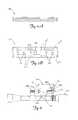
- the mounting system 100 in this embodimentincludes a scope 110 that is mounted on a weapon, which is a rifle 108 in this example, and a scope mount 102 .
- the electronic deviceis a rangefinder 104 in this example that can be operated remotely with a remote control pad 106 .
- the rangefinder 104is mounted over the scope 110 from a perspective of the hunter.
- FIG. 1Ban example of another embodiment in which the rangefinder 104 is mounted on the side of the scope 110 from the perspective of the hunter.
- FIG. 2Ais a side view of a mount 200 of one embodiment of the present invention.
- the mountis used in embodiments of the present invention to mount a device to the weapon.
- the mount 200includes a side plate 205 and a support plate 207 that generally makes the shape of an L.
- the support plate 207extends from a first end of the side plate 205 at generally a right angle.
- the support plate 207includes an engaging surface 206 to support a device and a stabilizing nub 204 designed to fit into a cavity of a device to provide stability and prevent the rotation of the device when mounted to the mount 200 .
- the support plate 207also includes a mounting aperture 208 .
- the mounting aperture 208is designed to allow a thumb screw (or any type of attaching device) to engage the device so that the device can be selectively coupled to the engaging surface 206 of the mount 200 .
- the side plate 205includes a mounting rail (or rail mount) 202 that is located near a second end of the side plate 205 that is opposite the first end of the side plate 205 . As illustrated, the mounting rail 202 extends from the side plate 205 in a direction that is opposite the direction the support plate 207 extends from the side plate 205 .
- FIG. 2Billustrates a back view of the mount 200 and in particular the mounting rail 202 .
- FIG. 2Cillustrates a top view of the mount 200 and in particular the stabilizing pin 204 and the mounting aperture 208 .
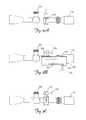
- FIG. 3Aillustrates a side view of a scope 110 with a quick mount scope mount 300 attached thereto. Also illustrated is the adjustment knob 304 of the scope 300 which adjusts the elevation and/or windage of the scope. It is important that the mount 200 and the device using the mount not interfere with the operations of the scope such as the operation of the adjustment knob 304 .
- FIG. 3Billustrates a mount 200 coupled to the scope 110 via the scope mount 300 .
- the scope mount 300engages the mounting rail 202 of mount 200 .
- the scope mount 300locks the mount onto the scope via a locking mechanism having a locking rod 305 that is rotated into a locking position.
- a scope mount 310 of one embodiment of the present inventionis illustrated.
- the scope mount 310includes a threaded thumb screw 312 with a triangle shaped head. The triangle shaped head allows for the applying of a twisting pressure to selectively lock and unlock the scope mount 312 to the scope 110 without the use of a screwdriver.
- FIG. 4a front view of the mount 200 attaching a video camera 400 to a scope 110 of one embodiment of the present invention is illustrated.
- a bottom side of camera 400is positioned to abut the engaging surface 206 of the mount 200 .
- the thumb screw mounting aperture 208allows a triangular shaped head thumb screw 306 to be threaded into internal threads 404 of the camera 400 to secure the camera to the mount 200 .
- a hand strap 402 of the camera 400can be wrapped around the mount as illustrated to further secure the camera to the mount 200 .
- FIG. 4further illustrates how the mounting rail 202 of the mount 200 is engaged with the scope mount 410 .
- FIG. 5illustrates the mounting system 500 on a rifle 108 .
- the mount 20allows for the camera to be mounted away from the elevation adjustment knob 309 of the scope 110 .
- the eyepiece 503 of camera 400is approximately at the same height as the eyepiece 505 of the scope 110 in relation to the hunter. That is, the eyepiece 503 of the camera 400 is basically at eye level with the aiming mechanism of the firearm. Accordingly, the hunter's movement to look between the scope and the view finder on the camera is minimal to avoid disruption of the hunt.
- Thisalso applies to other devices such as a rangefinder with a display that is positioned relatively at eye level with the scope as illustrated in FIG. 1B .
- a remote control pad 502that is designed to control the camera 400 .
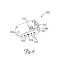
- Rangefinder 600includes attaching threads 604 adapted to engage the threads of a thumb screw. Accordingly, the rangefinder can be attached to the mounting plate 200 similar to the camera 400 of FIG. 4 . This embodiment is illustrated in FIG. 1B .
- the rangefinder 600also includes display 610 , a power button 605 , a mode switch button 607 , a battery cover 603 and a remote control port 602 that allows for the remote operation of the rangefinder 600 .
- the bottom surface of the rangefinder 600further includes 606 attaching apertures 606 . The attaching apertures 606 are used to mount a mounting rail to the rangefinder 600 .
- the bottom surface of the rangefinder 600further includes a stabilizing recess 608 that is designed to receive a stabilizing nub such as the stabilizing nub 204 on mount 200 .
- the battery cover 603 and the remote control port 602are positioned on a left side of the rangefinder 600 so that when the rangefinder 600 is mounted to a mount 200 as illustrated in FIG. 1B , the battery compartment and the port 602 are assessable.
- the mount 200is mounted to the other side of the scope 110
- the battery cover 603 and the remote control port 602are positioned on a right side of the rangefinder 600 to allow access to the battery chamber and the port 602 when mounted to the mount 200 in this embodiment.
- the placement of the power button 605 and mode switch button 607 on a rear side of the rangefinder 600allows for the ease of operation of the rangefinder 600 while the firearm is shouldered in a shooting position.
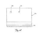
- FIGS. 7A and 7BAn example of a mounting rail 700 of one embodiment of the present invention is illustrated in FIGS. 7A and 7B .
- the mounting rail 700 of this embodimentincludes rail apertures 704 that are adapted to be aligned with the attaching apertures of the rangefinder 606 of other device. Screws or other attachment means are used to secure the rangefinder 606 to the mounting rail 700 through the rail apertures 704 and the associated attaching apertures 606 .
- a stabilizing recess 703is also designed to receive a stabilizing nub such as the stabilizing nub 204 on mount 200 .
- the rail apertures 704 , stabilizing nub as well as a rail thumb screw aperture 702are positioned between a first edge 705 and a second edge 707 of the mounting rail 700 .
- a first rail 701is positioned along the first edge 705 and a second rail 703 is positioned along a second edge 707 of the mounting rail 700 .
- First rail 701 and first edge 705are parallel to second rail 703 and second edge 707 .
- FIG. 8An illustration of a rangefinder attached to a scope 110 using the mounting rail 700 and a scope mount 706 is illustrated in FIG. 8 .
- the mounting rail 700is directly coupled to the scope mount 706 (through first clamp 708 of scope mount ring 709 ), and scope mount 706 is attached to scope 110 (through second clamp 710 of scope mount ring 709 ).
- first clamp (or rail clamp) 708extends upwardly to mounting rail 700
- second clamp (or ring clamp) 710extends downwardly to surround scope 110 , such that second clamp 710 is located below first clamp 708 .
- the mounting rail 700is coupled to a mount 200 that is coupled to the scope mount 706 .
- the mount rail thumb screw aperture 702is used to connect the mounting rail 700 and rangefinder 600 to the mount 200 via a thumb screw.
- the attaching threads 604 of the rangefinder 600can also be used to mount the rangefinder 600 to a tripod 900 as illustrated in FIG. 9 .
- the rangefinder 600can be remotely operated by a remote control pad 902 that is in communication with the remote control port 602 .
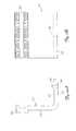
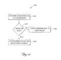
- FIG. 10One method of using a rangefinder 600 and a mount rail (or mounting rail) 700 of one embodiment of the present invention is illustrated in FIG. 10 .
- the methodbegins by attaching a mounting rail 700 to the rangefinder 600 ( 1102 ).
- the attachmentis at the bottom of the rangefinder. This illustration however, is shown by way of example and not by limitation. Accordingly, the location of the attachment of the mounting rail 700 is not limited to the bottom of the rangefinder. It is then determined if a mount 200 is already on the scope ( 1004 ). If a mount 200 is not on the scope ( 1004 ), the mounting rail 700 is directly attached to a scope mount 706 as illustrated in FIG. 8 . If a mount 200 is already on the scope ( 1004 ), the rangefinder 600 is attached to the mount 200 as illustrated in FIG. 1B .
- the mount 200can be used by a plurality of devices.
- One method of using the mount with devices in one embodiment of the present inventionis illustrated in FIG. 11 .
- a rail mount 202 on the mount 200is first attached to at least one scope mount 304 ( 1101 ). This is illustrated in FIG. 3B .
- the deviceis then attached to the mount ( 1104 ).
- the visual operation of the deviceis positioned by the mount to be at eye level with an aiming mechanism of the firearm which is in this embodiment, an eye piece of the scope.
- the eyepiece 503 of the camera 400is positioned approximately at eye level with the eyepiece 505 of the scope 110 and with the rangefinder example the display on the range finder is positioned approximately at eye level with the eyepiece of the scope ( FIG. 1B ).
- FIG. 12a mount 200 is coupled directly to a barrel 1200 of a firearm via scope mount 410 . That is, in this embodiment, the scope mount 410 is directly coupled to the barrel 1200 and not a scope. Also illustrated in FIG. 12 is the aiming mechanism 1210 of the firearm which is, in this embodiment, approximately at eye level with the operating device of the video camera 400 . Accordingly, the above embodiments of the present invention are not limited to being mounted to a scope.
- the range finder 1300includes a main housing 1302 and a power supply housing 1304 .
- the main housing 1302encases signal lens 1310 A through which a radar signal is passed and received.
- an operation panel 1306that is used to operate the range finder 1300 .
- the range finder 1300can also be operated by a remote unit 1305 .
- the remote unit 1305is adapted to be attached to a firearm in such a manner that it allows easy manipulation of the range finder 1300 .
- FIG. 13The range finder 1300 in this embodiment is adapted to be mounted to a scope 1309 that is in turn mounted to firearm 1311 .
- the range finder 1300is mounted to the scope 1309 with mounting brackets 1308 A and 1308 B.
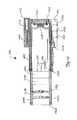
- the main housing 1302includes a first section 1450 and a second section 1454 .
- the first and second sections 1450 and 1454are connected by a plurality of attaching screws. In other embodiments, other attaching means are used and this invention is not limited to the use of attaching screws.
- an inter attachment section 1452abuts the first section 1450 .
- the inter attachment section 1450is adapted to hold a first and second signal lens 1310 A and 1310 B.
- this embodimentuses two signal lenses 1310 A and 1310 B, it will be understood in the art that other signal focusing method and other projection methods could be used and that this invention is not limited to two signal lenses 1310 A and 1310 B.
- signal generation circuit 1430is adapted to generate a signal that is projected out of the signal end 1460 of the range finder 1300 .
- the signal receiving circuit 1432is adapted to receive signals reflected off of an object and reflected back through the signal end 1460 of the range finder 1300 .
- the process circuit 1434is adapted to process the received signals to determine the distance to the object the signal was reflected off of.
- the control circuit 1435is adapted to control and synchronize the signal generation circuit 1430 , the signal receiving circuit 1432 and the process circuit 1434 based on operating signals provided by a user.
- a signal propagation time measuring methodis used to determine the distance to an object.
- a light-section method or a binocular sterosis method or other similar methodsare used. Accordingly, the present invention is not limited to a specific type of method of determining distances to an object.
- the power supply housing 1404in the second section 1454 of the range finder 1300 .
- the power supply 1414is a battery that is received in a cavity of the power supply housing 1404 .
- the power supply 1414is retained in the power supply housing 1404 with a threaded cap 1412 .
- the display 1416is coupled to the display end 1462 of the range finder 1300 .
- the display 1416is adapted to display indicia that represents the distance to an object when the range finder 1300 is activated.
- the displayis an LCD.
- a display circuit 1418is used to process signals from the processing circuit 1434 and to direct the display 1416 to display the distance.
- the control circuit 1425is controlled by operating switches 1420 , 1422 and 1424 on the operating panel 1406 and alternately through the jack 1426 which is selectively coupled to the remote unit 1305 .
- the control switchesmay include an on/off switch 1424 , an activation switch 1420 , a brightness control switch 1422 and the like.
- the switchesare activation buttons 1420 , 1422 and 1424 .
- the operating switches 1420 , 1422 and 1424are connected to control the control circuit 1425 .
- FIG. 15illustrates a rear view of the range finder 1300 coupled to a firearm 1311 .
- the range finder 1300includes the display 1416 which is located on the display end 1462 .
- the display 1416is encased in the display end 1462 of range finder 1300 .
- the display 1416extends from the display end 1462 of the range finder 1300 .
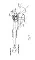
- FIG. 16is another perspective of the range finder 1300 of the present invention.
- FIG. 16illustrates the path of the beam or signal and the line of sight provided by the scope 109 .
- the mounting brackets 1600 A and 1600 B of the range finder 1300are integrated with the mounting brackets 1605 A and 1605 B that mount the scope 1309 to the firearm 1311 .
- Mounting brackets 1605 A and 1605 Bcan be referred to as the receiver of the scope.
- the mounting mechanism of the scopeis used to mount the range finder 1300 to the scope 1309 .
- a scope 1309need not be present.
- This embodimentis especially useful for individuals who have eye problems or disabilities that do not allow them to use a scope 1039 . Further in this embodiment, when the scope 1309 is not attached, the user can simply use the iron sights on the firearm to aim through the scope ring of the scope mounting brackets 1605 A, 1605 B.
Landscapes
- Engineering & Computer Science (AREA)
- General Engineering & Computer Science (AREA)
- Physics & Mathematics (AREA)
- Optics & Photonics (AREA)
- Aiming, Guidance, Guns With A Light Source, Armor, Camouflage, And Targets (AREA)
- Accessories Of Cameras (AREA)
Abstract
Description
This application is a continuation-in-part of U.S. patent application Ser. No. 11/327,123, filed Jan. 6, 2006, now U.S. Pat. No. 7,574,824, and titled “DEVICE MOUNT FOR A FIREARM”. This application is also a continuation-in-part of application Ser. No. 11/106,828, filed Apr. 15, 2005, now U.S. Pat. No. 7,643,132, and titled “RANGE FINDER”, which is a continuation-in-part of application Ser. No. 11/018,960, filed Dec. 21, 2004, now U.S. Pat. No. 7,100,321, and titled “RANGE FINDER”, now abandoned. Further, application Ser. No. 11/018,960 is a continuation of application Ser. No. 10/641,169, filed Aug. 14, 2003 and titled “RANGE FINDER”, now U.S. Pat. No. 6,988,331, which is a continuation of application Ser. No. 10/090,333, filed Mar. 4, 2002 and titled “RANGE FINDER”, now U.S. Pat. No. 6,615,531.
Range finders can be a useful tool when hunting for game. A ranger finder conveys the distance to an object (game target). This information is helpful to a hunter because it allows a hunter to determine if the target is beyond the range of a firearm or bow. Knowing the distance to a target also aids the hunter in the placement of the sight of the firearm or bow. For example, if the target is a great distance from a firearm, a hunter can raise the sight of the firearm over the target a select distance to compensate for the trajectory of a projectile (bullet) fired from the firearm. The distance found by the range finder can aid the hunter in determining how much the sight should be raised over the target.
An embodiment of the present invention is a device mounting system for a weapon having a scope. The mounting system includes an electronic device, a support plate, and a scope ring. The electronic device has a bottom surface. The support plate is engaged with the bottom surface and has a first mounting rail extending along a first side. The scope ring has a first clamp for coupling to the first mounting rail and a second clamp for surrounding the scope thereby attaching the electronic device to the scope.
In another embodiment, the device mounting system includes an electronic device, a support plate, a screw, a first mounting rail, and a scope ring. The electronic device has a substantially flat bottom surface and an attaching aperture extending into the bottom surface. The support plate extends horizontally below the bottom surface. The support plate has an attaching hole aligned to be coaxial with the attaching aperture of the electronic device. The screw extends through the hole and into the aperture thereby securing the electronic device to the support plate. The first mounting rail extends along a first side of the support plate. The scope ring has a rail clamp for attaching to the first mounting rail and a ring clamp for attaching to the scope.
In accordance with common practice, the various described features are not drawn to scale but are drawn to emphasize specific features relevant to the present invention. Reference characters denote like elements throughout Figures and text.
In the following detailed description, reference is made to the accompanying drawings, which form a part hereof, and in which is shown by way of illustration specific embodiments in which the inventions may be practiced. These embodiments are described in sufficient detail to enable those skilled in the art to practice the invention, and it is to be understood that other embodiments may be utilized and that logical, mechanical and electrical changes may be made without departing from the spirit and scope of the present invention. The following detailed description is, therefore, not to be taken in a limiting sense, and the scope of the present invention is defined only by the claims and equivalents thereof.
Embodiments of the present invention provide a mount that allows for the attachment of a device such as a video camera, rangefinder or the like, to a weapon. In particular, in one embodiment, the mount allows the device to be mounted to a scope of a weapon in a manner that does not hamper the operation of the scope (i.e. the elevation and/or windage adjustment knob for example) or other operations of the weapon. In another embodiment, a mounting rail adapted to mount a device to a firearm. In yet another embodiment, a rangefinder having a remote port and attaching treads that can be attached to the mount is provided.
Referring toFIG. 1A , a mountingsystem 100 of one embodiment of the present invention is illustrated. The mountingsystem 100 in this embodiment includes ascope 110 that is mounted on a weapon, which is arifle 108 in this example, and ascope mount 102. The electronic device is arangefinder 104 in this example that can be operated remotely with aremote control pad 106. In the example ofFIG. 1A , therangefinder 104 is mounted over thescope 110 from a perspective of the hunter. Referring toFIG. 1B , an example of another embodiment in which therangefinder 104 is mounted on the side of thescope 110 from the perspective of the hunter.
Referring toFIG. 4 , a front view of themount 200 attaching avideo camera 400 to ascope 110 of one embodiment of the present invention is illustrated. As illustrated, a bottom side ofcamera 400 is positioned to abut theengaging surface 206 of themount 200. The thumbscrew mounting aperture 208 allows a triangular shapedhead thumb screw 306 to be threaded intointernal threads 404 of thecamera 400 to secure the camera to themount 200. Moreover, ahand strap 402 of thecamera 400 can be wrapped around the mount as illustrated to further secure the camera to themount 200.FIG. 4 further illustrates how the mountingrail 202 of themount 200 is engaged with thescope mount 410.FIG. 5 illustrates the mountingsystem 500 on arifle 108. As illustrated, the mount20 allows for the camera to be mounted away from theelevation adjustment knob 309 of thescope 110. Moreover, as illustrated theeyepiece 503 ofcamera 400 is approximately at the same height as theeyepiece 505 of thescope 110 in relation to the hunter. That is, theeyepiece 503 of thecamera 400 is basically at eye level with the aiming mechanism of the firearm. Accordingly, the hunter's movement to look between the scope and the view finder on the camera is minimal to avoid disruption of the hunt. This also applies to other devices such as a rangefinder with a display that is positioned relatively at eye level with the scope as illustrated inFIG. 1B . Also illustrated inFIG. 5 is aremote control pad 502 that is designed to control thecamera 400.
An example of arangefinder 600 of one embodiment of the present invention is illustrated inFIG. 6 .Rangefinder 600 includes attachingthreads 604 adapted to engage the threads of a thumb screw. Accordingly, the rangefinder can be attached to the mountingplate 200 similar to thecamera 400 ofFIG. 4 . This embodiment is illustrated inFIG. 1B . Therangefinder 600 also includesdisplay 610, apower button 605, amode switch button 607, abattery cover 603 and aremote control port 602 that allows for the remote operation of therangefinder 600. Moreover, the bottom surface of therangefinder 600 further includes606 attachingapertures 606. The attachingapertures 606 are used to mount a mounting rail to therangefinder 600. The bottom surface of therangefinder 600 further includes a stabilizingrecess 608 that is designed to receive a stabilizing nub such as the stabilizingnub 204 onmount 200. In this embodiment, thebattery cover 603 and theremote control port 602 are positioned on a left side of therangefinder 600 so that when therangefinder 600 is mounted to amount 200 as illustrated inFIG. 1B , the battery compartment and theport 602 are assessable. In another embodiment, where themount 200 is mounted to the other side of thescope 110, thebattery cover 603 and theremote control port 602 are positioned on a right side of therangefinder 600 to allow access to the battery chamber and theport 602 when mounted to themount 200 in this embodiment. In addition, as illustrated inFIG. 1B , the placement of thepower button 605 andmode switch button 607 on a rear side of therangefinder 600 allows for the ease of operation of therangefinder 600 while the firearm is shouldered in a shooting position.
An example of a mountingrail 700 of one embodiment of the present invention is illustrated inFIGS. 7A and 7B . The mountingrail 700 of this embodiment includesrail apertures 704 that are adapted to be aligned with the attaching apertures of therangefinder 606 of other device. Screws or other attachment means are used to secure therangefinder 606 to the mountingrail 700 through therail apertures 704 and the associated attachingapertures 606. Further illustrated is a stabilizingrecess 703. This stabilizing recess is also designed to receive a stabilizing nub such as the stabilizingnub 204 onmount 200. Therail apertures 704, stabilizing nub as well as a railthumb screw aperture 702 are positioned between afirst edge 705 and asecond edge 707 of the mountingrail 700. Moreover as illustrated, afirst rail 701 is positioned along thefirst edge 705 and asecond rail 703 is positioned along asecond edge 707 of the mountingrail 700.First rail 701 andfirst edge 705 are parallel tosecond rail 703 andsecond edge 707.
An illustration of a rangefinder attached to ascope 110 using the mountingrail 700 and ascope mount 706 is illustrated inFIG. 8 . As illustrated in this embodiment, the mountingrail 700 is directly coupled to the scope mount706 (throughfirst clamp 708 of scope mount ring709), andscope mount 706 is attached to scope110 (throughsecond clamp 710 of scope mount ring709). As shown inFIG. 8 , first clamp (or rail clamp)708 extends upwardly to mountingrail 700, and second clamp (or ring clamp)710 extends downwardly to surroundscope 110, such thatsecond clamp 710 is located belowfirst clamp 708. In other embodiments, the mountingrail 700 is coupled to amount 200 that is coupled to thescope mount 706. In these embodiments, the mount railthumb screw aperture 702 is used to connect the mountingrail 700 andrangefinder 600 to themount 200 via a thumb screw. The attachingthreads 604 of therangefinder 600 can also be used to mount therangefinder 600 to atripod 900 as illustrated inFIG. 9 . As also illustrated inFIG. 9 , therangefinder 600 can be remotely operated by aremote control pad 902 that is in communication with theremote control port 602.
One method of using arangefinder 600 and a mount rail (or mounting rail)700 of one embodiment of the present invention is illustrated inFIG. 10 . As illustrated, the method begins by attaching a mountingrail 700 to the rangefinder600 (1102). In one embodiment, as illustrated inFIGS. 6 and 8 the attachment is at the bottom of the rangefinder. This illustration however, is shown by way of example and not by limitation. Accordingly, the location of the attachment of the mountingrail 700 is not limited to the bottom of the rangefinder. It is then determined if amount 200 is already on the scope (1004). If amount 200 is not on the scope (1004), the mountingrail 700 is directly attached to ascope mount 706 as illustrated inFIG. 8 . If amount 200 is already on the scope (1004), therangefinder 600 is attached to themount 200 as illustrated inFIG. 1B .
As discussed above, themount 200 can be used by a plurality of devices. One method of using the mount with devices in one embodiment of the present invention is illustrated inFIG. 11 . As illustrated, arail mount 202 on themount 200 is first attached to at least one scope mount304 (1101). This is illustrated inFIG. 3B . The device is then attached to the mount (1104). In one embodiment, the visual operation of the device is positioned by the mount to be at eye level with an aiming mechanism of the firearm which is in this embodiment, an eye piece of the scope. For example, as discussed above, with a video camera device400 (ofFIG. 5 ), theeyepiece 503 of thecamera 400 is positioned approximately at eye level with theeyepiece 505 of thescope 110 and with the rangefinder example the display on the range finder is positioned approximately at eye level with the eyepiece of the scope (FIG. 1B ).
Although, the above examples of the embodiments of the present invention illustrate a device being coupled to a scope of a firearm, other embodiments attach the device directly to a barrel of a firearm. For example, please refer toFIG. 12 . In the embodiment ofFIG. 12 , amount 200 is coupled directly to abarrel 1200 of a firearm viascope mount 410. That is, in this embodiment, thescope mount 410 is directly coupled to thebarrel 1200 and not a scope. Also illustrated inFIG. 12 is the aiming mechanism1210 of the firearm which is, in this embodiment, approximately at eye level with the operating device of thevideo camera 400. Accordingly, the above embodiments of the present invention are not limited to being mounted to a scope.
Referring toFIG. 13 , arangefinder 1300 of another embodiment of the present invention is illustrated. As illustrated, therange finder 1300 includes amain housing 1302 and apower supply housing 1304. Themain housing 1302 encasessignal lens 1310A through which a radar signal is passed and received. Also illustrated inFIG. 13 , is anoperation panel 1306 that is used to operate therange finder 1300. Therange finder 1300 can also be operated by aremote unit 1305. In particular, theremote unit 1305 is adapted to be attached to a firearm in such a manner that it allows easy manipulation of therange finder 1300. This feature is illustrated inFIG. 13 . Therange finder 1300 in this embodiment is adapted to be mounted to ascope 1309 that is in turn mounted tofirearm 1311. Moreover, in this embodiment therange finder 1300 is mounted to thescope 1309 with mountingbrackets 1308A and1308B.
Referring toFIG. 14 a cross-sectional top view of therange finder 1300 is illustrated. As illustrated, themain housing 1302 includes afirst section 1450 and asecond section 1454. The first andsecond sections inter attachment section 1452 abuts thefirst section 1450. Theinter attachment section 1450 is adapted to hold a first andsecond signal lens 1310A and1310B. Although, this embodiment uses twosignal lenses 1310A and1310B, it will be understood in the art that other signal focusing method and other projection methods could be used and that this invention is not limited to twosignal lenses 1310A and1310B. Also illustrated aresignal generation circuit 1430, signal receivingcircuit 1432, aprocess circuit 1434 and acontrol circuit 1435 that make up part of a range finding circuit. Thesignal generation circuit 1430 is adapted to generate a signal that is projected out of thesignal end 1460 of therange finder 1300. Thesignal receiving circuit 1432 is adapted to receive signals reflected off of an object and reflected back through thesignal end 1460 of therange finder 1300. Theprocess circuit 1434 is adapted to process the received signals to determine the distance to the object the signal was reflected off of. Thecontrol circuit 1435 is adapted to control and synchronize thesignal generation circuit 1430, thesignal receiving circuit 1432 and theprocess circuit 1434 based on operating signals provided by a user. In one embodiment, a signal propagation time measuring method is used to determine the distance to an object. In other embodiments, a light-section method or a binocular sterosis method or other similar methods are used. Accordingly, the present invention is not limited to a specific type of method of determining distances to an object.
Further illustrated inFIG. 14 , is thepower supply housing 1404 in thesecond section 1454 of therange finder 1300. In this embodiment, thepower supply 1414 is a battery that is received in a cavity of thepower supply housing 1404. Thepower supply 1414 is retained in thepower supply housing 1404 with a threadedcap 1412. In this embodiment, thedisplay 1416 is coupled to thedisplay end 1462 of therange finder 1300. Thedisplay 1416 is adapted to display indicia that represents the distance to an object when therange finder 1300 is activated. In one embodiment the display is an LCD. Adisplay circuit 1418 is used to process signals from theprocessing circuit 1434 and to direct thedisplay 1416 to display the distance. The control circuit1425 is controlled by operatingswitches operating panel 1406 and alternately through thejack 1426 which is selectively coupled to theremote unit 1305. The control switches may include an on/offswitch 1424, anactivation switch 1420, abrightness control switch 1422 and the like. In one embodiment, the switches areactivation buttons switches
While the invention has been described with reference to an exemplary embodiment(s), it will be understood by those skilled in the art that various changes may be made and equivalents may be substituted for elements thereof without departing from the scope of the invention. In addition, many modifications may be made to adapt a particular situation or material to the teachings of the invention without departing from the essential scope thereof. Therefore, it is intended that the invention not be limited to the particular embodiment(s) disclosed, but that the invention will include all embodiments falling within the scope of the appended claims.
Claims (17)
1. A device mounting system for a weapon having a scope, the mounting system comprising:
an electronic device having a bottom surface;
a support plate engaged with the bottom surface, the support plate being substantially planar between a first side and an opposite second side, the first side including a first mounting rail extending along a first edge and the second side including a second mounting rail extending along a second edge; and
a scope ring having a first clamp extending in an upward direction and clamping to both the first mounting rail and the second mounting rail, a second clamp extending in a downward direction and surrounding the scope thereby attaching the electronic device to the scope.
2. The device mounting system ofclaim 1 , wherein the electronic device is a range finder.
3. The device mounting system ofclaim 1 , wherein the electronic device is a video camera.
4. The device mounting system ofclaim 1 , wherein the support plate supports the electronic device above the scope.
5. The device mounting system ofclaim 1 , wherein the support plate supports the electronic device alongside the scope.
6. The device mounting system ofclaim 1 , wherein the second mounting rail extends parallel to the first mounting rail.
7. The device mounting system ofclaim 1 , further comprising:
a plurality of threaded attaching apertures extending upwardly into the electronic device from the bottom surface.
8. The device mounting system ofclaim 7 , further comprising:
a plurality of holes extending through the support plate and aligned to be coaxial with the attaching apertures.
9. The device mounting system ofclaim 8 , further comprising:
a plurality of screws inserted through the attaching holes into attaching apertures thereby securing the electronic device to the support plate.
10. A device mounting system for a weapon having a scope, the mounting system comprising:
an electronic device having a substantially flat bottom surface and an attaching aperture extending into the bottom surface;
a support plate extending horizontally below the bottom surface, the support plate being substantially planar between a first side and an opposite second side and having an attaching hole extending through the support plate between the first side and the second side, the attaching hole of the support plate aligned to be coaxial with the attaching aperture of the electronic device;
a screw extending through the hole and into the aperture thereby securing the electronic device to the support plate;
a first mounting rail extending along a first side of the support plate and a second mounting rail extending along a second side of the support plate; and
a scope ring having a rail clamp extending upwardly for clamping to both the first mounting rail and the second mounting rail, and a ring clamp extending downwardly for attaching to the scope.
11. The device mounting system ofclaim 10 , wherein the electronic device is a rangefinder.
12. The device mounting system ofclaim 10 , wherein the electronic device is a video camera.
13. The device mounting system ofclaim 10 , wherein the support plate supports the electronic device above the scope.
14. The device mounting system ofclaim 10 , wherein the support plate supports the electronic device alongside the scope.
15. The device mounting system ofclaim 10 , wherein the ring clamp is located below the rail clamp.
16. The device mounting system ofclaim 10 , further comprising:
a stabilizing aperture extending into the bottom surface and a stabilizing hole extending through the support plate, the stabilizing aperture aligned to be coaxial with the stabilizing hole; and
a stabilizing nub extending through the stabilizing hole and into the stabilizing aperture.
17. The device mounting system ofclaim 16 , further comprising:
a plurality of mounting apertures extending into the bottom surface of the electronic device;
a plurality of mounting holes extending through the support plate, the plurality of mounting holes aligned to be coaxial with the plurality of mounting apertures; and
a plurality of screws extending through the mounting holes and into the mounting apertures, thereby securing the electronic device to the support plate.
Priority Applications (1)
| Application Number | Priority Date | Filing Date | Title |
|---|---|---|---|
| US12/455,177US8156680B2 (en) | 2002-03-04 | 2009-05-29 | Device mounting system for a weapon |
Applications Claiming Priority (6)
| Application Number | Priority Date | Filing Date | Title |
|---|---|---|---|
| US10/090,333US6615531B1 (en) | 2002-03-04 | 2002-03-04 | Range finder |
| US10/641,169US6988331B2 (en) | 2002-03-04 | 2003-08-14 | Range finder |
| US11/018,960US7100321B2 (en) | 2002-03-04 | 2004-12-21 | Range finder |
| US11/106,828US7643132B2 (en) | 2002-03-04 | 2005-04-15 | Range finder |
| US11/327,123US7574824B2 (en) | 2006-01-06 | 2006-01-06 | Device mount for a firearm |
| US12/455,177US8156680B2 (en) | 2002-03-04 | 2009-05-29 | Device mounting system for a weapon |
Related Parent Applications (1)
| Application Number | Title | Priority Date | Filing Date |
|---|---|---|---|
| US11/327,123Continuation-In-PartUS7574824B2 (en) | 1999-03-08 | 2006-01-06 | Device mount for a firearm |
Publications (2)
| Publication Number | Publication Date |
|---|---|
| US20090255163A1 US20090255163A1 (en) | 2009-10-15 |
| US8156680B2true US8156680B2 (en) | 2012-04-17 |
Family
ID=41162823
Family Applications (1)
| Application Number | Title | Priority Date | Filing Date |
|---|---|---|---|
| US12/455,177Expired - Fee RelatedUS8156680B2 (en) | 2002-03-04 | 2009-05-29 | Device mounting system for a weapon |
Country Status (1)
| Country | Link |
|---|---|
| US (1) | US8156680B2 (en) |
Cited By (7)
| Publication number | Priority date | Publication date | Assignee | Title |
|---|---|---|---|---|
| US20120019811A1 (en)* | 2007-09-28 | 2012-01-26 | Cardinal Scientific, Inc. | Method and system for detecting retroreflectors |
| US20150107147A1 (en)* | 2013-10-22 | 2015-04-23 | John Douglas Hurley | Firearm Sighting Assembly |
| CN105300183A (en)* | 2015-10-30 | 2016-02-03 | 北京艾克利特光电科技有限公司 | Aiming device assembly capable of achieving automatic tracking and aiming |
| US20230380093A1 (en)* | 2022-05-19 | 2023-11-23 | Robert Stephan | Bow cable management system |
| USD1006764S1 (en) | 2022-05-19 | 2023-12-05 | Robert Stephan | Bow cable management system |
| US12078793B2 (en) | 2021-08-18 | 2024-09-03 | Maztech Industries, LLC | Weapon sight systems |
| US12422222B2 (en) | 2020-02-19 | 2025-09-23 | Maztech Industries, LLC | Weapon system with multi-function single-view scope |
Families Citing this family (5)
| Publication number | Priority date | Publication date | Assignee | Title |
|---|---|---|---|---|
| US7739822B1 (en)* | 2007-01-09 | 2010-06-22 | Larry Holmberg | Method and device for mounting an accessory to a firearm |
| US8819983B2 (en) | 2010-12-17 | 2014-09-02 | Jeff Tate | Systems, methods, and apparatus for securing a recording device to a hunting apparatus |
| US20120167442A1 (en)* | 2011-01-04 | 2012-07-05 | Larue Mark C | Sight mount enabling inverted mounting of firearm sighting device |
| WO2017027609A1 (en)* | 2015-08-10 | 2017-02-16 | Val Simmons | Scope phone mount |
| US10876816B2 (en)* | 2015-11-16 | 2020-12-29 | Hookshottactical, Llc | Camera sight devices and rear viewing camera smart phone mount for a firearm |
Citations (241)
| Publication number | Priority date | Publication date | Assignee | Title |
|---|---|---|---|---|
| US521761A (en) | 1894-06-19 | Velocipede | ||
| US547912A (en) | 1895-10-15 | Storm-door shield | ||
| US619214A (en) | 1899-02-07 | Curtain-pole | ||
| US674229A (en) | 1900-03-21 | 1901-05-14 | John E Windle | Cloth-doubling machine. |
| US845165A (en) | 1906-09-25 | 1907-02-26 | Davis Piano Player Company | Automatic organ-action. |
| US899639A (en) | 1908-06-04 | 1908-09-29 | Gillette Vibber Co | Box-connector for electric installation. |
| US1452651A (en) | 1921-10-15 | 1923-04-24 | Charles H Norrlin | Target finder for firearms |
| US1480147A (en) | 1920-06-28 | 1924-01-08 | Brandt & Krell Engineering Com | Stringer clamp |
| US1550849A (en) | 1925-02-26 | 1925-08-25 | Szalardi Adalbert | Camera gun |
| US1735164A (en) | 1927-04-21 | 1929-11-12 | Samuel G Green | Recoil mount for guns |
| US1757244A (en) | 1928-03-05 | 1930-05-06 | Samuel G Green | Mount for guns |
| US1923926A (en) | 1930-03-05 | 1933-08-22 | Ch Faure Roux Ets | Elastic cord |
| US2072387A (en) | 1933-12-27 | 1937-03-02 | Stephen P F Sneed | Safety cordage |
| US2101479A (en) | 1935-03-22 | 1937-12-07 | Cleveland H Schenk | Night target range finder |
| US2129606A (en) | 1937-04-19 | 1938-09-06 | Nisenson Julius | Adjustable cord lock |
| US2270902A (en) | 1939-11-25 | 1942-01-27 | George A Rubissow | Antivibration means and method of use of same |
| US2296308A (en) | 1942-09-22 | Indicator | ||
| US2354998A (en) | 1941-12-01 | 1944-08-01 | Ku Chain Ki | Reading stand |
| US2416769A (en) | 1945-04-27 | 1947-03-04 | Charles O Palmer | Photographic attachment for firearms |
| US2450466A (en) | 1947-01-06 | 1948-10-05 | Carlson Richard | Telescope mounting for guns |
| US2456554A (en) | 1945-10-12 | 1948-12-14 | United Carr Fastener Corp | Connector for cords or cables |
| US2483711A (en) | 1946-10-14 | 1949-10-04 | Micro Engineering Corp | Camera holder |
| US2576007A (en) | 1949-01-05 | 1951-11-20 | George M Fischer | Gun sight mounting |
| US2604933A (en) | 1947-03-25 | 1952-07-29 | Wingfoot Corp | Resilient support for seat cushions |
| US2664797A (en) | 1950-08-25 | 1954-01-05 | Chester M Thrasher | Camera gun |
| US2814118A (en) | 1955-02-14 | 1957-11-26 | Paul I Evans | Sight mount for a rocket launcher |
| US2817233A (en) | 1956-05-25 | 1957-12-24 | Ethell J Dower | Flexible firing mount |
| US2943547A (en) | 1958-11-03 | 1960-07-05 | Marian S Martin | Firearm supported camera mount |
| US3035880A (en) | 1960-11-23 | 1962-05-22 | Woodward Inc | Self adjusting drawer guide |
| US3062114A (en) | 1959-12-18 | 1962-11-06 | Palos Gabor | Mounting for gun cameras |
| US3065666A (en) | 1959-12-07 | 1962-11-27 | Herbert F Sampson | Underwater camera construction |
| US3078728A (en) | 1950-04-11 | 1963-02-26 | Carleton H Schlesman | Fluid driven gyroscope |
| US3165972A (en) | 1963-10-28 | 1965-01-19 | Harold B Cumbo | Gyro weapons stabilizer |
| US3371899A (en) | 1965-08-13 | 1968-03-05 | Johnson John Algot | Shock absorbing apparatus |
| US3427102A (en) | 1966-07-29 | 1969-02-11 | Lloyd H Wade | Combined firearm and motion picture camera |
| US3483623A (en) | 1968-08-20 | 1969-12-16 | George R Kruzell | Shock-proof telescopic gun sight mount |
| US3502062A (en) | 1967-01-23 | 1970-03-24 | Donald E Shurts | Archery bow with gyroscopic stabilizer |
| US3545356A (en) | 1969-04-07 | 1970-12-08 | Jens C Nielsen | Camera telescope apparatus for guns |
| US3684378A (en) | 1970-09-04 | 1972-08-15 | Joseph S Lord | Dark current correction circuit for photosensing devices |
| US3684376A (en) | 1970-09-10 | 1972-08-15 | Donald E Lessard | Ranger-finder in a telescopic sight |
| US3737232A (en) | 1970-10-15 | 1973-06-05 | R Milburn | Firearm telescopic range finder |
| US3782822A (en) | 1971-11-08 | 1974-01-01 | M Spence | Method and apparatus for automatic ranging with variable power telescopic gun sight |
| US3785261A (en) | 1972-09-05 | 1974-01-15 | R Ganteaume | Event recorder |
| US3834052A (en) | 1973-09-21 | 1974-09-10 | Weaver Co W | Mount for gunsight |
| US3945134A (en) | 1974-09-13 | 1976-03-23 | Alpine Research, Inc. | Ski boot |
| US3986285A (en)* | 1975-05-16 | 1976-10-19 | Krisay Robert J | Detachable top side mount |
| US4000403A (en) | 1973-12-03 | 1976-12-28 | Rice Marion D | Multi-purpose light |
| US4026054A (en) | 1976-02-02 | 1977-05-31 | Snyder Wesley L | Laser aiming system for weapons |
| US4027414A (en) | 1976-01-05 | 1977-06-07 | Felix Thomas R | Rifle scope mount |
| US4069414A (en) | 1976-06-04 | 1978-01-17 | Bell Arthur O | Firearm sight light |
| US4162696A (en) | 1977-04-02 | 1979-07-31 | Rollei-Werke Franke & Heidecke | Support for a camera |
| GB2024558A (en) | 1978-06-22 | 1980-01-09 | Bofors Ab | Laser Range Finder |
| US4223770A (en) | 1977-11-29 | 1980-09-23 | Messerschmitt-Bolkow-Blohm Gmbh | Shaft drive alternately for both directions of rotation |
| US4234112A (en) | 1978-04-10 | 1980-11-18 | Gallant Guy G | Water ski rack |
| US4283743A (en) | 1980-04-14 | 1981-08-11 | Motorola, Inc. | Yoke mounting assembly for a video camera |
| US4296725A (en) | 1979-07-27 | 1981-10-27 | Broderick Ronald J | Archery bow improvement and camera therefor |
| USD261545S (en) | 1980-03-03 | 1981-10-27 | Holmberg Larry A | Adjustable plug for shotgun shell chamber |
| US4309095A (en) | 1980-11-03 | 1982-01-05 | Buckley Frederick P | Camera mounting device |
| US4316342A (en) | 1980-04-28 | 1982-02-23 | Griggs Jay P | Recoil absorber and redirector mechanism for gun stock |
| US4349169A (en) | 1980-08-14 | 1982-09-14 | The United States Of America As Represented By The Secretary Of The Air Force | Continuous force actuator |
| USD268910S (en) | 1980-05-28 | 1983-05-10 | Benchmark | Electronic distance measuring instrument |
| GB2114770A (en) | 1981-12-11 | 1983-08-24 | Marcello Baldacchini | Telemetry device |
| US4439032A (en) | 1982-09-27 | 1984-03-27 | Pedco | Portable camera support |
| US4514907A (en) | 1982-03-12 | 1985-05-07 | Saltzman Leonard F | Bow and arrow sighting device |
| US4516296A (en) | 1983-10-05 | 1985-05-14 | Zsi, Inc. | Tubing clamp and method of making the same |
| US4531052A (en) | 1982-09-24 | 1985-07-23 | Moore Sidney D | Microcomputer-controlled optical apparatus for surveying, rangefinding and trajectory-compensating functions |
| US4561204A (en) | 1983-07-06 | 1985-12-31 | Binion W Sidney | Reticle display for small arms |
| US4564322A (en) | 1983-09-06 | 1986-01-14 | Stapley Keith D | Drill scope |
| US4597211A (en) | 1983-08-15 | 1986-07-01 | Miles Paul S | Self-alternating rear sights for double-barrel firearms |
| US4606629A (en) | 1983-12-13 | 1986-08-19 | Quantime, Inc. | Laser archery distance device |
| US4617741A (en) | 1984-12-17 | 1986-10-21 | Bordeaux Marvin L | Electronic rangefinder for archery |
| US4640258A (en) | 1984-11-01 | 1987-02-03 | Streamlight, Inc. | Archery shooting bow with stabilizing flashlight |
| US4643159A (en) | 1985-10-07 | 1987-02-17 | Ryan Lawrence W | Automatic camera actuating apparatus for an archery bow |
| US4730190A (en) | 1986-10-29 | 1988-03-08 | Winlam Company | Hand-held measuring device |
| US4733838A (en)* | 1984-10-22 | 1988-03-29 | Lely Cornelis V D | Transportable computer |
| US4753528A (en) | 1983-12-13 | 1988-06-28 | Quantime, Inc. | Laser archery distance device |
| US4777352A (en) | 1982-09-24 | 1988-10-11 | Moore Sidney D | Microcontroller operated optical apparatus for surveying rangefinding and trajectory compensating functions |
| US4786204A (en) | 1986-02-24 | 1988-11-22 | The Eversman Mfg. Company | Clamping apparatus with bi-directional clamping device |
| US4786966A (en) | 1986-07-10 | 1988-11-22 | Varo, Inc. | Head mounted video display and remote camera system |
| US4827348A (en) | 1988-05-02 | 1989-05-02 | Polaroid Corporation | Exposure control system for dual mode electronic imaging camera |
| US4835621A (en) | 1987-11-04 | 1989-05-30 | Black John W | Gun mounted video camera |
| US4884137A (en) | 1986-07-10 | 1989-11-28 | Varo, Inc. | Head mounted video display and remote camera system |
| US4890128A (en) | 1988-10-24 | 1989-12-26 | Bruce Kania | Shock absorber for a bow mounted camera |
| US4907567A (en) | 1988-05-12 | 1990-03-13 | Henrich Richard L | Adjustable multi function rotary bow stabilizer |
| US4910717A (en) | 1987-08-07 | 1990-03-20 | Sonin, Inc. | Apparatus for measuring distances |
| US4939863A (en) | 1988-08-31 | 1990-07-10 | Emerging Technologies, Inc. | Laser aiming device for firearms, archery bows, and crossbows |
| US4970589A (en) | 1986-07-10 | 1990-11-13 | Varo, Inc. | Head mounted video display and remote camera system |
| US4974575A (en) | 1990-02-12 | 1990-12-04 | Mitchell Frank E | Bow blind |
| USD313361S (en) | 1988-07-26 | 1991-01-01 | Sonin, Inc. | Electronic distance measuring instrument |
| US4989024A (en)* | 1988-11-22 | 1991-01-29 | Myers Jeff D | Photographic gun |
| US4993833A (en) | 1987-10-09 | 1991-02-19 | Kontron Elektronik Gmbh | Weapon aiming device |
| US4996866A (en) | 1989-03-06 | 1991-03-05 | M.E.P. Macchine Elettroniche Piegatrici Spa | Orientable bending assembly |
| US5005213A (en) | 1986-07-10 | 1991-04-02 | Varo, Inc. | Head mounted video display and remote camera system |
| US5020262A (en) | 1990-09-04 | 1991-06-04 | Pena Louis T | Camera mount for rifle scopes |
| US5026158A (en) | 1988-07-15 | 1991-06-25 | Golubic Victor G | Apparatus and method for displaying and storing impact points of firearm projectiles on a sight field of view |
| US5033219A (en) | 1990-02-06 | 1991-07-23 | Emerging Technologies, Inc. | Modular laser aiming system |
| US5035390A (en) | 1990-04-11 | 1991-07-30 | Joseph Sanders | Adapter for attaching an animal call to a firearm |
| US5056410A (en) | 1989-09-22 | 1991-10-15 | Zero Coil, Inc. | Firearm recoil absorber |
| US5113745A (en) | 1990-08-23 | 1992-05-19 | David Palmer | Stabilizing device for a gun |
| US5121147A (en)* | 1990-03-29 | 1992-06-09 | Sony Corporation | Video camera carrying handle supporting battery and accessories |
| US5161310A (en) | 1991-07-26 | 1992-11-10 | Stoot Joseph L | Sighting device for an archery bow |
| US5200827A (en) | 1986-07-10 | 1993-04-06 | Varo, Inc. | Head mounted video display and remote camera system |
| US5244430A (en) | 1992-07-30 | 1993-09-14 | Legursky Roy A | Turkey caller and support apparatus |
| US5262837A (en) | 1992-10-21 | 1993-11-16 | Norm Pacific Automation Corp. | Laser range finder |
| US5265896A (en) | 1991-12-03 | 1993-11-30 | Kravitz Harley A | Vehicle step kit and method |
| US5297533A (en) | 1992-12-22 | 1994-03-29 | Virgil Cook | Light holder and stabilizer attachment for bow |
| US5326061A (en) | 1991-11-01 | 1994-07-05 | Hamilton Glen R | Shelf mounting means |
| US5339793A (en) | 1993-05-13 | 1994-08-23 | Findley Alan T | Bow stabilizer |
| US5373657A (en) | 1992-07-15 | 1994-12-20 | Progenics Corporation | Sight apparatus for firearms |
| US5418609A (en) | 1993-09-14 | 1995-05-23 | Laser Technology, Inc. | Apparatus and method for mounting a range finding instrument to a theodolite telescope |
| US5450993A (en) | 1994-02-07 | 1995-09-19 | Motorola, Inc. | Carry holder |
| US5455625A (en) | 1993-09-23 | 1995-10-03 | Rosco Inc. | Video camera unit, protective enclosure and power circuit for same, particularly for use in vehicles |
| US5456157A (en) | 1992-12-02 | 1995-10-10 | Computing Devices Canada Ltd. | Weapon aiming system |
| US5479712A (en) | 1994-06-17 | 1996-01-02 | Hargrove; Jeffrey B. | Triangulation rangefinder for archers |
| US5507272A (en) | 1994-08-19 | 1996-04-16 | Scantlen; Jayson R. | Adjustable bow sight |
| US5520164A (en) | 1994-05-16 | 1996-05-28 | Huddleston; Jerry R. | Quick connect/disconnect adapter for archery related accessories |
| US5525970A (en)* | 1994-04-12 | 1996-06-11 | The United States Of America As Represented By The Secretary Of The Army | Safety system and technique for multi-aperture optical systems |
| US5528325A (en)* | 1995-03-29 | 1996-06-18 | Perez; Sixto R. | Power bracket for photographic cameras |
| USD371084S (en) | 1995-05-19 | 1996-06-25 | Sokkia Co., Ltd. | Range meter using a laser light wave |
| US5531149A (en) | 1994-02-15 | 1996-07-02 | Schubert; David P. | Anti-car jacking device |
| US5555665A (en) | 1995-04-12 | 1996-09-17 | Fore; John C. | Scent-releasing pole for attracting deer |
| US5575072A (en) | 1994-11-08 | 1996-11-19 | Eldridge; Gary | Electric archery bow sight/range finder |
| US5607091A (en) | 1995-07-05 | 1997-03-04 | Musacchia; John | Universal game call adapter and holder |
| US5606818A (en) | 1995-04-21 | 1997-03-04 | Hardee; Timothy G. | Multi-purpose ambidextrous rifle scope mount |
| US5611324A (en) | 1995-09-28 | 1997-03-18 | Kursinsky; Steven D. | Camera actuating archery apparatus |
| US5669147A (en) | 1992-04-23 | 1997-09-23 | Nikon Corporation | Tilt sensor |
| US5669174A (en) | 1993-06-08 | 1997-09-23 | Teetzel; James W. | Laser range finding apparatus |
| US5687910A (en) | 1996-01-30 | 1997-11-18 | King Bros. Industries | Sprinkler riser connecting apparatus |
| US5711104A (en) | 1996-12-19 | 1998-01-27 | Schmitz; Geoffrey W. | Small arms visual aiming system, a method for aiming a firearm, and headgear for use therewith |
| USD390483S (en) | 1996-08-22 | 1998-02-10 | Laser Technology, Inc. | Compact laser-based distance measuring equipment |
| US5739859A (en) | 1994-10-21 | 1998-04-14 | Sony Corporation | Video camera with a rotatably mounted viewfinder |
| US5811720A (en) | 1997-06-16 | 1998-09-22 | Quinnell; Glenn D. | Shooting rest with recoil reduction system |
| US5815251A (en) | 1993-05-15 | 1998-09-29 | Leica Geosystems Ag | Device for distance measurement |
| US5822621A (en) | 1996-04-10 | 1998-10-13 | Eastman Kodak Company | Camera with smile sound |
| US5831718A (en) | 1997-08-21 | 1998-11-03 | Raytheon Company | Portable laser range finder and digital compass assembly |
| US5834676A (en) | 1996-08-12 | 1998-11-10 | Sight Unseen | Weapon-mounted location-monitoring apparatus |
| US5845165A (en) | 1997-05-23 | 1998-12-01 | Mcmahan; Charles B. | Rifle style camera |
| US5859693A (en) | 1997-08-26 | 1999-01-12 | Laser Technology, Inc. | Modularized laser-based survey system |
| US5887375A (en)* | 1997-11-19 | 1999-03-30 | Watson; Jerry Wade | Camera mount for firearms |
| US5892617A (en) | 1997-07-28 | 1999-04-06 | Wallace; Robert E. | Multi-function day/night observation, ranging, and sighting device and method of its operation |
| US5895131A (en) | 1997-01-18 | 1999-04-20 | Asahi Kogaku Kogyo Kabushiki Kaisha | Range finder system for camera |
| US5911215A (en) | 1997-02-28 | 1999-06-15 | Fisher, Jr.; James Conner | Attachment mechanism for an accessory for an archer's bow |
| US5926260A (en) | 1995-01-19 | 1999-07-20 | Laser Technology, Inc. | Compact laser-based distance measuring apparatus |
| US5937562A (en) | 1997-11-17 | 1999-08-17 | Henry Technical Services, Incorporated | Optical accessory |
| US5941434A (en) | 1996-10-11 | 1999-08-24 | Green; Mark R. | Multi-strap holder |
| US5944041A (en) | 1998-06-01 | 1999-08-31 | Kitchens; Kirk | Portable blind |
| US5963748A (en)* | 1997-10-22 | 1999-10-05 | Glasson; Michael J. | Camera elevating and viewing apparatus |
| US5964054A (en) | 1996-04-25 | 1999-10-12 | Galfidi, Jr.; Joe | Game caller |
| US5973315A (en) | 1998-02-18 | 1999-10-26 | Litton Systems, Inc. | Multi-functional day/night observation, ranging, and sighting device with active optical target acquisition and method of its operation |
| USD421229S (en) | 1998-10-19 | 2000-02-29 | Optex Co., Ltd. | Laser distance meter |
| US6029643A (en) | 1998-01-09 | 2000-02-29 | Golfieri; David A. | Bow sighting unit and stand |
| US6042277A (en)* | 1997-03-27 | 2000-03-28 | Errington; Dale R. | Camera flash bracket |
| US6070355A (en) | 1998-05-07 | 2000-06-06 | Day; Frederick A. | Video scope |
| US6073352A (en) | 1998-03-19 | 2000-06-13 | Laser Technology, Inc. | Laser bow sight apparatus |
| US6137564A (en) | 1998-02-03 | 2000-10-24 | Robert Bosch Gmbh | Distance measuring device |
| USD432930S (en) | 1999-10-05 | 2000-10-31 | Solar Wide Industrial Ltd. | Distance measuring device |
| US6154971A (en) | 1998-07-01 | 2000-12-05 | Perkins; Ronald Keith | Sight apparatus |
| US6192614B1 (en) | 1999-07-23 | 2001-02-27 | Daniel Cliburn | Video mounting system for firearm |
| US6252706B1 (en) | 1997-03-12 | 2001-06-26 | Gabriel Guary | Telescopic sight for individual weapon with automatic aiming and adjustment |
| US6269581B1 (en) | 1999-04-12 | 2001-08-07 | John Groh | Range compensating rifle scope |
| US20010018311A1 (en) | 1998-10-19 | 2001-08-30 | John Musacchia | Elevated game call with attachment feature |
| US6286796B1 (en) | 1999-12-28 | 2001-09-11 | Andy J. Pugliesi | Video camera mounting apparatus |
| US6288386B1 (en) | 1998-10-28 | 2001-09-11 | Itt Manufacturing Enterprises Inc. | Circuit having a flexible printed circuit board for electronically controlling a night vision device and night vision device including the same |
| US6296581B1 (en) | 1995-02-01 | 2001-10-02 | Terry L. Sever | Collapsible batting practice apparatus, and connectable plastic tubing used in same |
| US6304289B1 (en) | 1996-10-28 | 2001-10-16 | Director General Of The 1St District Port Construction Bureau, Ministry Of Transport | Submerged laser television and submerged laser visual recognizer |
| US20010035440A1 (en) | 2000-03-13 | 2001-11-01 | Danielson Steven L. | Firearm rest having shock absorbing line |
| US6331887B1 (en) | 1997-02-14 | 2001-12-18 | Kabushiki Kaisha Yaskawa Denki | Outdoor range finder |
| US6336285B1 (en) | 1997-03-17 | 2002-01-08 | Allen P. Baumer | Sighting apparatus |
| US6341201B1 (en) | 1997-09-30 | 2002-01-22 | Fuji Photo Optical Co., Ltd. | Remotely controllable camera system |
| US6396571B2 (en) | 2000-07-24 | 2002-05-28 | Kabushiki Kaisha Topcon | Portable type distance measuring apparatus |
| US6398571B1 (en) | 1999-02-23 | 2002-06-04 | Sumitomo Wiring Systems, Ltd. | Waterproof insulation displacement connector and method of manufacturing it |
| US20020067475A1 (en) | 2000-11-09 | 2002-06-06 | Reinhard Waibel | Optoelectronic laser distance-measuring instrument |
| US6408140B1 (en) | 2000-05-24 | 2002-06-18 | Eastman Kodak Company | Dual film image and electronic image capture camera with electronic image verification of film image misfocus |
| US20020078577A1 (en) | 2000-12-26 | 2002-06-27 | Aldred Robert C. | Archery bow sight |
| US20020087475A1 (en) | 1998-12-28 | 2002-07-04 | Nobuya Okayama | Method and system for preventing illegal use of digital contents, processing program thereof, and recording medium for the program |
| USD460367S1 (en) | 2000-09-28 | 2002-07-16 | Leica Geosystems Ag | Casing of a device for the measurement of distances |
| US6425697B1 (en) | 1999-03-17 | 2002-07-30 | Jeff C. Potts | Universal camera mounting assembly |
| US20020109057A1 (en) | 1998-11-09 | 2002-08-15 | Wooten Donald W. | Adjustable weapon auxiliary mount |
| US6450816B1 (en) | 1998-03-09 | 2002-09-17 | Oerlikon Contraves Ag | Identification system |
| US20020171755A1 (en) | 2001-05-18 | 2002-11-21 | Fuji Photo Film Co., Ltd. | Digital camera changeable operation sequence |
| US6487809B1 (en) | 2001-12-19 | 2002-12-03 | American Technologies Network Corporation | Optical sight system with wide range of shooting distances |
| US6494196B2 (en) | 1999-12-15 | 2002-12-17 | New Archery Products Corp. | Archery bow stabilizer having energy directors |
| US20030013392A1 (en) | 2001-06-15 | 2003-01-16 | Laurent Guillermin | Device for clamping an ophthalmic lens |
| US6526956B1 (en) | 2001-02-20 | 2003-03-04 | Robert Jordan Hankins | Archery bow attachment |
| USD472826S1 (en) | 2002-05-29 | 2003-04-08 | Agatec | Distance measuring device |
| US6556245B1 (en) | 1999-03-08 | 2003-04-29 | Larry Allan Holmberg | Game hunting video camera |
| US20030133092A1 (en) | 2001-04-13 | 2003-07-17 | Rogers Philip L. | Multi-function optical system and assembly |
| US6598331B1 (en) | 2002-01-29 | 2003-07-29 | John R. Thibodeaux | Shotgun sighting device |
| US20030163943A1 (en) | 2002-03-04 | 2003-09-04 | Larry Holmberg | Range finder |
| US20030168484A1 (en) | 1999-12-13 | 2003-09-11 | All Rite Products, Inc. | Offset holding device |
| US6623182B2 (en) | 2002-01-14 | 2003-09-23 | Bruce Tatera | Hunter's tree-mounted camera mount |
| US20040000083A1 (en) | 2002-07-01 | 2004-01-01 | Grant James Emmett | Multiple rail adapter |
| US6678988B1 (en) | 2002-07-23 | 2004-01-20 | Cape Aerospace, Llc. | Recoil dampening device for gun sight |
| US6681755B2 (en) | 2000-03-07 | 2004-01-27 | Pierre Pujos | Vibration dampening device |
| US6693702B2 (en) | 2000-09-11 | 2004-02-17 | Mark Rogers | Laser range estimation aid |
| US6704097B2 (en) | 2000-05-31 | 2004-03-09 | Hilti Aktiengesellschaft | Optoelectronic distance measuring device and operating method determined therefor |
| US20040051865A1 (en) | 2001-10-05 | 2004-03-18 | Joerg Stierle | Device for distance measurement |
| USD488315S1 (en) | 2003-06-02 | 2004-04-13 | Natuzzi S.P.A. | Sofa |
| US6722076B2 (en) | 2002-09-06 | 2004-04-20 | Douglas E. Nielsen | Apparatus and method for attaching devices to a weapon |
| US6742299B2 (en) | 1999-05-24 | 2004-06-01 | Strandstar Instruments, L.L.C. | Laser device for use in adjusting a firearm's sight |
| US20040114129A1 (en) | 2002-11-19 | 2004-06-17 | Torsten Gogolla | Handheld laser distance measuring device with extreme value measuring process |
| US20040135991A1 (en) | 2002-11-13 | 2004-07-15 | Torsten Gogolla | Portable laser distance measuring device |
| US6772076B2 (en) | 2002-04-24 | 2004-08-03 | Ffc Limited | Electromagnetic field analysis method based on FDTD method, medium representation method in electromagnetic field analysis, simulation device, and storage medium |
| US6784920B2 (en) | 1996-03-11 | 2004-08-31 | Eric D. Weber | Fishing surveillance device |
| US6796038B2 (en) | 2002-12-17 | 2004-09-28 | Lee N. Humphries | Range adjustable laser sight for archery |
| US6813025B2 (en) | 2001-06-19 | 2004-11-02 | Ralph C. Edwards | Modular scope |
| US6815251B1 (en) | 1999-02-01 | 2004-11-09 | Micron Technology, Inc. | High density modularity for IC's |
| US6819866B2 (en) | 2001-03-05 | 2004-11-16 | Underwater Systems & Technology Pty Ltd. | Watertight universal housing |
| US6819495B2 (en) | 2002-06-17 | 2004-11-16 | International Technologies (Lasers) Ltd. | Auxiliary optical unit attachable to optical devices, particularly telescopic gun sights |
| US20040257437A1 (en) | 2003-06-20 | 2004-12-23 | Todd Lesseu | Sure shot mount |
| US20050035245A1 (en) | 2003-08-13 | 2005-02-17 | Enrique Morales | Camera support and control device |
| US6886288B1 (en) | 2003-12-19 | 2005-05-03 | Terry L. Yocum | Device for mounting a scope to carrying handle of a rifle |
| US20050123883A1 (en) | 2003-12-09 | 2005-06-09 | Kennen John S. | Simulated hunting apparatus and method for using same |
| US20050195385A1 (en) | 2002-03-04 | 2005-09-08 | Larry Holmberg | Range finder |
| US20050241210A1 (en) | 2004-02-11 | 2005-11-03 | Vitronics Inc. | Dual sight scope system and method |
| US20050246910A1 (en) | 2004-05-07 | 2005-11-10 | Mowers Michael S | Weaponry camera sight |
| US20050252062A1 (en) | 2004-05-12 | 2005-11-17 | Scrogin Andrew D | Infrared range-finding and compensating scope for use with a projectile firing device |
| US20050268521A1 (en) | 2004-06-07 | 2005-12-08 | Raytheon Company | Electronic sight for firearm, and method of operating same |
| US20050268519A1 (en) | 2004-06-07 | 2005-12-08 | Dov Pikielny | Optical accessory with mounting rail |
| US20060010761A1 (en) | 2004-03-10 | 2006-01-19 | Raytheon Company A Corporation Of The State Of Delaware | Weapon sight having analog on-target indicators |
| US7088506B2 (en) | 2003-04-28 | 2006-08-08 | Leupold & Stevens, Inc. | Compact spotting scope with side focus control |
| WO2006090356A1 (en) | 2005-02-23 | 2006-08-31 | Elbit Systems Ltd. | Add-on laser gated imaging device for associating with an optical assembly |
| US20060215149A1 (en) | 2003-11-26 | 2006-09-28 | Labelle John | Rangefinder and method for collecting calibration data |
| US7128354B2 (en) | 2004-05-21 | 2006-10-31 | Wu Chin-Chang | Apparatus for supporting a video camera |
| WO2006133029A2 (en) | 2005-06-03 | 2006-12-14 | Gilmore Sports Concepts, Inc. | Combination red dot sight and range indicator apparatus |
| US20070008187A1 (en) | 2005-06-10 | 2007-01-11 | Schmidt R K | System And Method For Determining Aircraft Hard Landing Events From Inertial And Aircraft Reference Frame Data |
| US20070031142A1 (en) | 2005-08-04 | 2007-02-08 | Deer Ridge Innovations, Inc. | Gun and bow camera mount |
| US7188978B2 (en) | 2004-11-15 | 2007-03-13 | Streamlight, Inc. | Light mountable on a mounting rail |
| US20070081817A1 (en) | 2005-10-11 | 2007-04-12 | John Soulvie | Camera support base |
| US20070125930A1 (en) | 2005-12-05 | 2007-06-07 | Chong-Shien Tsai | Anti-shock device |
| US20070130848A1 (en) | 2005-12-13 | 2007-06-14 | Chong-Shien Tsai | Anti shock device |
| EP1804017A1 (en) | 2005-12-30 | 2007-07-04 | Bushnell Corporation | Telescopic sight and method for compensating for bullett trajectory deviations |
| US20070157503A1 (en) | 2006-01-06 | 2007-07-12 | Larry Holmberg | Device mount |
| US7269920B2 (en) | 2004-03-10 | 2007-09-18 | Raytheon Company | Weapon sight with ballistics information persistence |
| US20070277421A1 (en) | 2004-06-14 | 2007-12-06 | Bushnell Performance Optics | Telescopic sight and method for automatically compensating for bullet trajectory deviations |
| US20080000463A1 (en) | 2006-06-30 | 2008-01-03 | Larry Holmberg | Crossbow device mount |
| US20080000465A1 (en) | 2006-06-30 | 2008-01-03 | Larry Holmberg | Adaptor for device mount |
| US20080060248A1 (en) | 2006-09-08 | 2008-03-13 | Jerrold Scott Pine | Stealth Laser Sighting System For Firearms |
| US20080087784A1 (en) | 2006-10-17 | 2008-04-17 | Larry Holmberg | Device mount with stabilizing function |
| US7614805B2 (en) | 2006-11-07 | 2009-11-10 | Joseph Showalter | Image capture device mounting assembly for firearm |
| US7789574B2 (en) | 2007-11-16 | 2010-09-07 | Du-Bro Products, Inc. | Camera mount |
- 2009
- 2009-05-29USUS12/455,177patent/US8156680B2/ennot_activeExpired - Fee Related
Patent Citations (260)
| Publication number | Priority date | Publication date | Assignee | Title |
|---|---|---|---|---|
| US2296308A (en) | 1942-09-22 | Indicator | ||
| US547912A (en) | 1895-10-15 | Storm-door shield | ||
| US619214A (en) | 1899-02-07 | Curtain-pole | ||
| US521761A (en) | 1894-06-19 | Velocipede | ||
| US674229A (en) | 1900-03-21 | 1901-05-14 | John E Windle | Cloth-doubling machine. |
| US845165A (en) | 1906-09-25 | 1907-02-26 | Davis Piano Player Company | Automatic organ-action. |
| US899639A (en) | 1908-06-04 | 1908-09-29 | Gillette Vibber Co | Box-connector for electric installation. |
| US1480147A (en) | 1920-06-28 | 1924-01-08 | Brandt & Krell Engineering Com | Stringer clamp |
| US1452651A (en) | 1921-10-15 | 1923-04-24 | Charles H Norrlin | Target finder for firearms |
| US1550849A (en) | 1925-02-26 | 1925-08-25 | Szalardi Adalbert | Camera gun |
| US1735164A (en) | 1927-04-21 | 1929-11-12 | Samuel G Green | Recoil mount for guns |
| US1757244A (en) | 1928-03-05 | 1930-05-06 | Samuel G Green | Mount for guns |
| US1923926A (en) | 1930-03-05 | 1933-08-22 | Ch Faure Roux Ets | Elastic cord |
| US2072387A (en) | 1933-12-27 | 1937-03-02 | Stephen P F Sneed | Safety cordage |
| US2101479A (en) | 1935-03-22 | 1937-12-07 | Cleveland H Schenk | Night target range finder |
| US2129606A (en) | 1937-04-19 | 1938-09-06 | Nisenson Julius | Adjustable cord lock |
| US2270902A (en) | 1939-11-25 | 1942-01-27 | George A Rubissow | Antivibration means and method of use of same |
| US2354998A (en) | 1941-12-01 | 1944-08-01 | Ku Chain Ki | Reading stand |
| US2416769A (en) | 1945-04-27 | 1947-03-04 | Charles O Palmer | Photographic attachment for firearms |
| US2456554A (en) | 1945-10-12 | 1948-12-14 | United Carr Fastener Corp | Connector for cords or cables |
| US2483711A (en) | 1946-10-14 | 1949-10-04 | Micro Engineering Corp | Camera holder |
| US2450466A (en) | 1947-01-06 | 1948-10-05 | Carlson Richard | Telescope mounting for guns |
| US2604933A (en) | 1947-03-25 | 1952-07-29 | Wingfoot Corp | Resilient support for seat cushions |
| US2576007A (en) | 1949-01-05 | 1951-11-20 | George M Fischer | Gun sight mounting |
| US3078728A (en) | 1950-04-11 | 1963-02-26 | Carleton H Schlesman | Fluid driven gyroscope |
| US2664797A (en) | 1950-08-25 | 1954-01-05 | Chester M Thrasher | Camera gun |
| US2814118A (en) | 1955-02-14 | 1957-11-26 | Paul I Evans | Sight mount for a rocket launcher |
| US2817233A (en) | 1956-05-25 | 1957-12-24 | Ethell J Dower | Flexible firing mount |
| US2943547A (en) | 1958-11-03 | 1960-07-05 | Marian S Martin | Firearm supported camera mount |
| US3065666A (en) | 1959-12-07 | 1962-11-27 | Herbert F Sampson | Underwater camera construction |
| US3062114A (en) | 1959-12-18 | 1962-11-06 | Palos Gabor | Mounting for gun cameras |
| US3035880A (en) | 1960-11-23 | 1962-05-22 | Woodward Inc | Self adjusting drawer guide |
| US3165972A (en) | 1963-10-28 | 1965-01-19 | Harold B Cumbo | Gyro weapons stabilizer |
| US3371899A (en) | 1965-08-13 | 1968-03-05 | Johnson John Algot | Shock absorbing apparatus |
| US3427102A (en) | 1966-07-29 | 1969-02-11 | Lloyd H Wade | Combined firearm and motion picture camera |
| US3502062A (en) | 1967-01-23 | 1970-03-24 | Donald E Shurts | Archery bow with gyroscopic stabilizer |
| US3483623A (en) | 1968-08-20 | 1969-12-16 | George R Kruzell | Shock-proof telescopic gun sight mount |
| US3545356A (en) | 1969-04-07 | 1970-12-08 | Jens C Nielsen | Camera telescope apparatus for guns |
| US3684378A (en) | 1970-09-04 | 1972-08-15 | Joseph S Lord | Dark current correction circuit for photosensing devices |
| US3684376A (en) | 1970-09-10 | 1972-08-15 | Donald E Lessard | Ranger-finder in a telescopic sight |
| US3737232A (en) | 1970-10-15 | 1973-06-05 | R Milburn | Firearm telescopic range finder |
| US3782822A (en) | 1971-11-08 | 1974-01-01 | M Spence | Method and apparatus for automatic ranging with variable power telescopic gun sight |
| US3785261A (en) | 1972-09-05 | 1974-01-15 | R Ganteaume | Event recorder |
| US3834052A (en) | 1973-09-21 | 1974-09-10 | Weaver Co W | Mount for gunsight |
| US3834052B1 (en) | 1973-09-21 | 1987-06-30 | ||
| US4000403A (en) | 1973-12-03 | 1976-12-28 | Rice Marion D | Multi-purpose light |
| US3945134A (en) | 1974-09-13 | 1976-03-23 | Alpine Research, Inc. | Ski boot |
| US3986285A (en)* | 1975-05-16 | 1976-10-19 | Krisay Robert J | Detachable top side mount |
| US4027414A (en) | 1976-01-05 | 1977-06-07 | Felix Thomas R | Rifle scope mount |
| US4026054A (en) | 1976-02-02 | 1977-05-31 | Snyder Wesley L | Laser aiming system for weapons |
| US4069414A (en) | 1976-06-04 | 1978-01-17 | Bell Arthur O | Firearm sight light |
| US4162696A (en) | 1977-04-02 | 1979-07-31 | Rollei-Werke Franke & Heidecke | Support for a camera |
| US4223770A (en) | 1977-11-29 | 1980-09-23 | Messerschmitt-Bolkow-Blohm Gmbh | Shaft drive alternately for both directions of rotation |
| US4234112A (en) | 1978-04-10 | 1980-11-18 | Gallant Guy G | Water ski rack |
| GB2024558A (en) | 1978-06-22 | 1980-01-09 | Bofors Ab | Laser Range Finder |
| US4296725A (en) | 1979-07-27 | 1981-10-27 | Broderick Ronald J | Archery bow improvement and camera therefor |
| USD261545S (en) | 1980-03-03 | 1981-10-27 | Holmberg Larry A | Adjustable plug for shotgun shell chamber |
| US4283743A (en) | 1980-04-14 | 1981-08-11 | Motorola, Inc. | Yoke mounting assembly for a video camera |
| US4316342A (en) | 1980-04-28 | 1982-02-23 | Griggs Jay P | Recoil absorber and redirector mechanism for gun stock |
| USD268910S (en) | 1980-05-28 | 1983-05-10 | Benchmark | Electronic distance measuring instrument |
| US4349169A (en) | 1980-08-14 | 1982-09-14 | The United States Of America As Represented By The Secretary Of The Air Force | Continuous force actuator |
| US4309095A (en) | 1980-11-03 | 1982-01-05 | Buckley Frederick P | Camera mounting device |
| GB2114770A (en) | 1981-12-11 | 1983-08-24 | Marcello Baldacchini | Telemetry device |
| US4514907A (en) | 1982-03-12 | 1985-05-07 | Saltzman Leonard F | Bow and arrow sighting device |
| US4531052A (en) | 1982-09-24 | 1985-07-23 | Moore Sidney D | Microcomputer-controlled optical apparatus for surveying, rangefinding and trajectory-compensating functions |
| US4777352A (en) | 1982-09-24 | 1988-10-11 | Moore Sidney D | Microcontroller operated optical apparatus for surveying rangefinding and trajectory compensating functions |
| US4439032A (en) | 1982-09-27 | 1984-03-27 | Pedco | Portable camera support |
| US4561204A (en) | 1983-07-06 | 1985-12-31 | Binion W Sidney | Reticle display for small arms |
| US4597211A (en) | 1983-08-15 | 1986-07-01 | Miles Paul S | Self-alternating rear sights for double-barrel firearms |
| US4564322A (en) | 1983-09-06 | 1986-01-14 | Stapley Keith D | Drill scope |
| US4516296A (en) | 1983-10-05 | 1985-05-14 | Zsi, Inc. | Tubing clamp and method of making the same |
| US4606629A (en) | 1983-12-13 | 1986-08-19 | Quantime, Inc. | Laser archery distance device |
| US4753528A (en) | 1983-12-13 | 1988-06-28 | Quantime, Inc. | Laser archery distance device |
| US4733838A (en)* | 1984-10-22 | 1988-03-29 | Lely Cornelis V D | Transportable computer |
| US4640258A (en) | 1984-11-01 | 1987-02-03 | Streamlight, Inc. | Archery shooting bow with stabilizing flashlight |
| US4617741A (en) | 1984-12-17 | 1986-10-21 | Bordeaux Marvin L | Electronic rangefinder for archery |
| US4643159A (en) | 1985-10-07 | 1987-02-17 | Ryan Lawrence W | Automatic camera actuating apparatus for an archery bow |
| US4786204A (en) | 1986-02-24 | 1988-11-22 | The Eversman Mfg. Company | Clamping apparatus with bi-directional clamping device |
| US4970589A (en) | 1986-07-10 | 1990-11-13 | Varo, Inc. | Head mounted video display and remote camera system |
| US4786966A (en) | 1986-07-10 | 1988-11-22 | Varo, Inc. | Head mounted video display and remote camera system |
| US5200827A (en) | 1986-07-10 | 1993-04-06 | Varo, Inc. | Head mounted video display and remote camera system |
| US4884137A (en) | 1986-07-10 | 1989-11-28 | Varo, Inc. | Head mounted video display and remote camera system |
| US5005213A (en) | 1986-07-10 | 1991-04-02 | Varo, Inc. | Head mounted video display and remote camera system |
| US4730190A (en) | 1986-10-29 | 1988-03-08 | Winlam Company | Hand-held measuring device |
| US4910717A (en) | 1987-08-07 | 1990-03-20 | Sonin, Inc. | Apparatus for measuring distances |
| US4993833A (en) | 1987-10-09 | 1991-02-19 | Kontron Elektronik Gmbh | Weapon aiming device |
| US4835621A (en) | 1987-11-04 | 1989-05-30 | Black John W | Gun mounted video camera |
| US4827348A (en) | 1988-05-02 | 1989-05-02 | Polaroid Corporation | Exposure control system for dual mode electronic imaging camera |
| US4907567A (en) | 1988-05-12 | 1990-03-13 | Henrich Richard L | Adjustable multi function rotary bow stabilizer |
| US5026158A (en) | 1988-07-15 | 1991-06-25 | Golubic Victor G | Apparatus and method for displaying and storing impact points of firearm projectiles on a sight field of view |
| USD313361S (en) | 1988-07-26 | 1991-01-01 | Sonin, Inc. | Electronic distance measuring instrument |
| US4939863A (en) | 1988-08-31 | 1990-07-10 | Emerging Technologies, Inc. | Laser aiming device for firearms, archery bows, and crossbows |
| US4890128A (en) | 1988-10-24 | 1989-12-26 | Bruce Kania | Shock absorber for a bow mounted camera |
| US4989024A (en)* | 1988-11-22 | 1991-01-29 | Myers Jeff D | Photographic gun |
| US4996866A (en) | 1989-03-06 | 1991-03-05 | M.E.P. Macchine Elettroniche Piegatrici Spa | Orientable bending assembly |
| US5056410A (en) | 1989-09-22 | 1991-10-15 | Zero Coil, Inc. | Firearm recoil absorber |
| US5033219A (en) | 1990-02-06 | 1991-07-23 | Emerging Technologies, Inc. | Modular laser aiming system |
| US4974575A (en) | 1990-02-12 | 1990-12-04 | Mitchell Frank E | Bow blind |
| US5121147A (en)* | 1990-03-29 | 1992-06-09 | Sony Corporation | Video camera carrying handle supporting battery and accessories |
| US5035390A (en) | 1990-04-11 | 1991-07-30 | Joseph Sanders | Adapter for attaching an animal call to a firearm |
| US5113745A (en) | 1990-08-23 | 1992-05-19 | David Palmer | Stabilizing device for a gun |
| US5020262A (en) | 1990-09-04 | 1991-06-04 | Pena Louis T | Camera mount for rifle scopes |
| US5161310A (en) | 1991-07-26 | 1992-11-10 | Stoot Joseph L | Sighting device for an archery bow |
| US5326061A (en) | 1991-11-01 | 1994-07-05 | Hamilton Glen R | Shelf mounting means |
| US5265896A (en) | 1991-12-03 | 1993-11-30 | Kravitz Harley A | Vehicle step kit and method |
| US5669147A (en) | 1992-04-23 | 1997-09-23 | Nikon Corporation | Tilt sensor |
| US5373657A (en) | 1992-07-15 | 1994-12-20 | Progenics Corporation | Sight apparatus for firearms |
| US5244430A (en) | 1992-07-30 | 1993-09-14 | Legursky Roy A | Turkey caller and support apparatus |
| US5262837A (en) | 1992-10-21 | 1993-11-16 | Norm Pacific Automation Corp. | Laser range finder |
| US5456157A (en) | 1992-12-02 | 1995-10-10 | Computing Devices Canada Ltd. | Weapon aiming system |
| US5686690A (en) | 1992-12-02 | 1997-11-11 | Computing Devices Canada Ltd. | Weapon aiming system |
| US5297533A (en) | 1992-12-22 | 1994-03-29 | Virgil Cook | Light holder and stabilizer attachment for bow |
| US5339793A (en) | 1993-05-13 | 1994-08-23 | Findley Alan T | Bow stabilizer |
| US5815251A (en) | 1993-05-15 | 1998-09-29 | Leica Geosystems Ag | Device for distance measurement |
| US5669174A (en) | 1993-06-08 | 1997-09-23 | Teetzel; James W. | Laser range finding apparatus |
| US5418609A (en) | 1993-09-14 | 1995-05-23 | Laser Technology, Inc. | Apparatus and method for mounting a range finding instrument to a theodolite telescope |
| US5455625A (en) | 1993-09-23 | 1995-10-03 | Rosco Inc. | Video camera unit, protective enclosure and power circuit for same, particularly for use in vehicles |
| US5450993A (en) | 1994-02-07 | 1995-09-19 | Motorola, Inc. | Carry holder |
| US5531149A (en) | 1994-02-15 | 1996-07-02 | Schubert; David P. | Anti-car jacking device |
| US5525970A (en)* | 1994-04-12 | 1996-06-11 | The United States Of America As Represented By The Secretary Of The Army | Safety system and technique for multi-aperture optical systems |
| US5520164A (en) | 1994-05-16 | 1996-05-28 | Huddleston; Jerry R. | Quick connect/disconnect adapter for archery related accessories |
| US5479712A (en) | 1994-06-17 | 1996-01-02 | Hargrove; Jeffrey B. | Triangulation rangefinder for archers |
| US5507272A (en) | 1994-08-19 | 1996-04-16 | Scantlen; Jayson R. | Adjustable bow sight |
| US5739859A (en) | 1994-10-21 | 1998-04-14 | Sony Corporation | Video camera with a rotatably mounted viewfinder |
| US5575072A (en) | 1994-11-08 | 1996-11-19 | Eldridge; Gary | Electric archery bow sight/range finder |
| US5926260A (en) | 1995-01-19 | 1999-07-20 | Laser Technology, Inc. | Compact laser-based distance measuring apparatus |
| US6296581B1 (en) | 1995-02-01 | 2001-10-02 | Terry L. Sever | Collapsible batting practice apparatus, and connectable plastic tubing used in same |
| US5528325A (en)* | 1995-03-29 | 1996-06-18 | Perez; Sixto R. | Power bracket for photographic cameras |
| US5555665A (en) | 1995-04-12 | 1996-09-17 | Fore; John C. | Scent-releasing pole for attracting deer |
| US5606818A (en) | 1995-04-21 | 1997-03-04 | Hardee; Timothy G. | Multi-purpose ambidextrous rifle scope mount |
| USD371084S (en) | 1995-05-19 | 1996-06-25 | Sokkia Co., Ltd. | Range meter using a laser light wave |
| US5607091A (en) | 1995-07-05 | 1997-03-04 | Musacchia; John | Universal game call adapter and holder |
| US5611324A (en) | 1995-09-28 | 1997-03-18 | Kursinsky; Steven D. | Camera actuating archery apparatus |
| US5687910A (en) | 1996-01-30 | 1997-11-18 | King Bros. Industries | Sprinkler riser connecting apparatus |
| US6784920B2 (en) | 1996-03-11 | 2004-08-31 | Eric D. Weber | Fishing surveillance device |
| US5822621A (en) | 1996-04-10 | 1998-10-13 | Eastman Kodak Company | Camera with smile sound |
| US5964054A (en) | 1996-04-25 | 1999-10-12 | Galfidi, Jr.; Joe | Game caller |
| US5834676A (en) | 1996-08-12 | 1998-11-10 | Sight Unseen | Weapon-mounted location-monitoring apparatus |
| USD390483S (en) | 1996-08-22 | 1998-02-10 | Laser Technology, Inc. | Compact laser-based distance measuring equipment |
| US5941434A (en) | 1996-10-11 | 1999-08-24 | Green; Mark R. | Multi-strap holder |
| US6304289B1 (en) | 1996-10-28 | 2001-10-16 | Director General Of The 1St District Port Construction Bureau, Ministry Of Transport | Submerged laser television and submerged laser visual recognizer |
| US5711104A (en) | 1996-12-19 | 1998-01-27 | Schmitz; Geoffrey W. | Small arms visual aiming system, a method for aiming a firearm, and headgear for use therewith |
| US5895131A (en) | 1997-01-18 | 1999-04-20 | Asahi Kogaku Kogyo Kabushiki Kaisha | Range finder system for camera |
| US6331887B1 (en) | 1997-02-14 | 2001-12-18 | Kabushiki Kaisha Yaskawa Denki | Outdoor range finder |
| US5911215A (en) | 1997-02-28 | 1999-06-15 | Fisher, Jr.; James Conner | Attachment mechanism for an accessory for an archer's bow |
| US6252706B1 (en) | 1997-03-12 | 2001-06-26 | Gabriel Guary | Telescopic sight for individual weapon with automatic aiming and adjustment |
| US6336285B1 (en) | 1997-03-17 | 2002-01-08 | Allen P. Baumer | Sighting apparatus |
| US6042277A (en)* | 1997-03-27 | 2000-03-28 | Errington; Dale R. | Camera flash bracket |
| US5845165A (en) | 1997-05-23 | 1998-12-01 | Mcmahan; Charles B. | Rifle style camera |
| US5811720A (en) | 1997-06-16 | 1998-09-22 | Quinnell; Glenn D. | Shooting rest with recoil reduction system |
| US5892617A (en) | 1997-07-28 | 1999-04-06 | Wallace; Robert E. | Multi-function day/night observation, ranging, and sighting device and method of its operation |
| US5831718A (en) | 1997-08-21 | 1998-11-03 | Raytheon Company | Portable laser range finder and digital compass assembly |
| US5949529A (en) | 1997-08-26 | 1999-09-07 | Laser Technology, Inc. | Modularized laser-based survey system |
| US5859693A (en) | 1997-08-26 | 1999-01-12 | Laser Technology, Inc. | Modularized laser-based survey system |
| US6341201B1 (en) | 1997-09-30 | 2002-01-22 | Fuji Photo Optical Co., Ltd. | Remotely controllable camera system |
| US5963748A (en)* | 1997-10-22 | 1999-10-05 | Glasson; Michael J. | Camera elevating and viewing apparatus |
| US5937562A (en) | 1997-11-17 | 1999-08-17 | Henry Technical Services, Incorporated | Optical accessory |
| US5887375A (en)* | 1997-11-19 | 1999-03-30 | Watson; Jerry Wade | Camera mount for firearms |
| US6029643A (en) | 1998-01-09 | 2000-02-29 | Golfieri; David A. | Bow sighting unit and stand |
| US6137564A (en) | 1998-02-03 | 2000-10-24 | Robert Bosch Gmbh | Distance measuring device |
| US5973315A (en) | 1998-02-18 | 1999-10-26 | Litton Systems, Inc. | Multi-functional day/night observation, ranging, and sighting device with active optical target acquisition and method of its operation |
| US6450816B1 (en) | 1998-03-09 | 2002-09-17 | Oerlikon Contraves Ag | Identification system |
| US6073352A (en) | 1998-03-19 | 2000-06-13 | Laser Technology, Inc. | Laser bow sight apparatus |
| US6070355A (en) | 1998-05-07 | 2000-06-06 | Day; Frederick A. | Video scope |
| US5944041A (en) | 1998-06-01 | 1999-08-31 | Kitchens; Kirk | Portable blind |
| US6397483B1 (en) | 1998-07-01 | 2002-06-04 | Ronald Keith Perkins | Sight apparatus |
| US6154971A (en) | 1998-07-01 | 2000-12-05 | Perkins; Ronald Keith | Sight apparatus |
| USD421229S (en) | 1998-10-19 | 2000-02-29 | Optex Co., Ltd. | Laser distance meter |
| US20010018311A1 (en) | 1998-10-19 | 2001-08-30 | John Musacchia | Elevated game call with attachment feature |
| US6288386B1 (en) | 1998-10-28 | 2001-09-11 | Itt Manufacturing Enterprises Inc. | Circuit having a flexible printed circuit board for electronically controlling a night vision device and night vision device including the same |
| US20020109057A1 (en) | 1998-11-09 | 2002-08-15 | Wooten Donald W. | Adjustable weapon auxiliary mount |
| US20020087475A1 (en) | 1998-12-28 | 2002-07-04 | Nobuya Okayama | Method and system for preventing illegal use of digital contents, processing program thereof, and recording medium for the program |
| US6815251B1 (en) | 1999-02-01 | 2004-11-09 | Micron Technology, Inc. | High density modularity for IC's |
| US6398571B1 (en) | 1999-02-23 | 2002-06-04 | Sumitomo Wiring Systems, Ltd. | Waterproof insulation displacement connector and method of manufacturing it |
| US20040183942A1 (en) | 1999-03-08 | 2004-09-23 | Larry Holmberg | Camera lens and display |
| US6556245B1 (en) | 1999-03-08 | 2003-04-29 | Larry Allan Holmberg | Game hunting video camera |
| US7006144B2 (en) | 1999-03-08 | 2006-02-28 | Larry Allan Holmberg | Video camera recorder |
| US6425697B1 (en) | 1999-03-17 | 2002-07-30 | Jeff C. Potts | Universal camera mounting assembly |
| US6269581B1 (en) | 1999-04-12 | 2001-08-07 | John Groh | Range compensating rifle scope |
| US6742299B2 (en) | 1999-05-24 | 2004-06-01 | Strandstar Instruments, L.L.C. | Laser device for use in adjusting a firearm's sight |
| US6192614B1 (en) | 1999-07-23 | 2001-02-27 | Daniel Cliburn | Video mounting system for firearm |
| USD432930S (en) | 1999-10-05 | 2000-10-31 | Solar Wide Industrial Ltd. | Distance measuring device |
| US20030168484A1 (en) | 1999-12-13 | 2003-09-11 | All Rite Products, Inc. | Offset holding device |
| US6494196B2 (en) | 1999-12-15 | 2002-12-17 | New Archery Products Corp. | Archery bow stabilizer having energy directors |
| US6286796B1 (en) | 1999-12-28 | 2001-09-11 | Andy J. Pugliesi | Video camera mounting apparatus |
| US6681755B2 (en) | 2000-03-07 | 2004-01-27 | Pierre Pujos | Vibration dampening device |
| US20010035440A1 (en) | 2000-03-13 | 2001-11-01 | Danielson Steven L. | Firearm rest having shock absorbing line |
| US6408140B1 (en) | 2000-05-24 | 2002-06-18 | Eastman Kodak Company | Dual film image and electronic image capture camera with electronic image verification of film image misfocus |
| US6704097B2 (en) | 2000-05-31 | 2004-03-09 | Hilti Aktiengesellschaft | Optoelectronic distance measuring device and operating method determined therefor |
| US6396571B2 (en) | 2000-07-24 | 2002-05-28 | Kabushiki Kaisha Topcon | Portable type distance measuring apparatus |
| US6693702B2 (en) | 2000-09-11 | 2004-02-17 | Mark Rogers | Laser range estimation aid |
| USD460369S1 (en) | 2000-09-28 | 2002-07-16 | Leica Geosystems Ag | Casing of a device for the measurement of distances |
| USD460367S1 (en) | 2000-09-28 | 2002-07-16 | Leica Geosystems Ag | Casing of a device for the measurement of distances |
| USD460368S1 (en) | 2000-09-28 | 2002-07-16 | Leica Geosystems Ag | Casing of a device for the measurement of distances |
| US20020067475A1 (en) | 2000-11-09 | 2002-06-06 | Reinhard Waibel | Optoelectronic laser distance-measuring instrument |
| US6624881B2 (en) | 2000-11-09 | 2003-09-23 | Hilti Aktiengesellschaft | Optoelectronic laser distance-measuring instrument |
| US20020078577A1 (en) | 2000-12-26 | 2002-06-27 | Aldred Robert C. | Archery bow sight |
| US6526956B1 (en) | 2001-02-20 | 2003-03-04 | Robert Jordan Hankins | Archery bow attachment |
| US6819866B2 (en) | 2001-03-05 | 2004-11-16 | Underwater Systems & Technology Pty Ltd. | Watertight universal housing |
| US20030133092A1 (en) | 2001-04-13 | 2003-07-17 | Rogers Philip L. | Multi-function optical system and assembly |
| US20020171755A1 (en) | 2001-05-18 | 2002-11-21 | Fuji Photo Film Co., Ltd. | Digital camera changeable operation sequence |
| US20030013392A1 (en) | 2001-06-15 | 2003-01-16 | Laurent Guillermin | Device for clamping an ophthalmic lens |
| US6813025B2 (en) | 2001-06-19 | 2004-11-02 | Ralph C. Edwards | Modular scope |
| US20040051865A1 (en) | 2001-10-05 | 2004-03-18 | Joerg Stierle | Device for distance measurement |
| US6487809B1 (en) | 2001-12-19 | 2002-12-03 | American Technologies Network Corporation | Optical sight system with wide range of shooting distances |
| US6623182B2 (en) | 2002-01-14 | 2003-09-23 | Bruce Tatera | Hunter's tree-mounted camera mount |
| US6598331B1 (en) | 2002-01-29 | 2003-07-29 | John R. Thibodeaux | Shotgun sighting device |
| US6615531B1 (en) | 2002-03-04 | 2003-09-09 | Larry Holmberg | Range finder |
| US20040079018A1 (en) | 2002-03-04 | 2004-04-29 | Larry Holmberg | Range finder |
| US20050195385A1 (en) | 2002-03-04 | 2005-09-08 | Larry Holmberg | Range finder |
| US20040194364A1 (en) | 2002-03-04 | 2004-10-07 | Larry Holmberg | Range finder |
| US6988331B2 (en) | 2002-03-04 | 2006-01-24 | Larry Holmberg | Range finder |
| US20030163943A1 (en) | 2002-03-04 | 2003-09-04 | Larry Holmberg | Range finder |
| US6772076B2 (en) | 2002-04-24 | 2004-08-03 | Ffc Limited | Electromagnetic field analysis method based on FDTD method, medium representation method in electromagnetic field analysis, simulation device, and storage medium |
| USD472826S1 (en) | 2002-05-29 | 2003-04-08 | Agatec | Distance measuring device |
| US6819495B2 (en) | 2002-06-17 | 2004-11-16 | International Technologies (Lasers) Ltd. | Auxiliary optical unit attachable to optical devices, particularly telescopic gun sights |
| US20040000083A1 (en) | 2002-07-01 | 2004-01-01 | Grant James Emmett | Multiple rail adapter |
| US20040016169A1 (en) | 2002-07-23 | 2004-01-29 | Poff Charles Richard | Recoil dampening device for gun sight |
| US6678988B1 (en) | 2002-07-23 | 2004-01-20 | Cape Aerospace, Llc. | Recoil dampening device for gun sight |
| US6722076B2 (en) | 2002-09-06 | 2004-04-20 | Douglas E. Nielsen | Apparatus and method for attaching devices to a weapon |
| US20040135991A1 (en) | 2002-11-13 | 2004-07-15 | Torsten Gogolla | Portable laser distance measuring device |
| US20040114129A1 (en) | 2002-11-19 | 2004-06-17 | Torsten Gogolla | Handheld laser distance measuring device with extreme value measuring process |
| US6796038B2 (en) | 2002-12-17 | 2004-09-28 | Lee N. Humphries | Range adjustable laser sight for archery |
| US7088506B2 (en) | 2003-04-28 | 2006-08-08 | Leupold & Stevens, Inc. | Compact spotting scope with side focus control |
| USD488315S1 (en) | 2003-06-02 | 2004-04-13 | Natuzzi S.P.A. | Sofa |
| US20040257437A1 (en) | 2003-06-20 | 2004-12-23 | Todd Lesseu | Sure shot mount |
| US6932305B2 (en) | 2003-08-13 | 2005-08-23 | Enrique Morales | Camera support and control device |
| US20050035245A1 (en) | 2003-08-13 | 2005-02-17 | Enrique Morales | Camera support and control device |
| US20060215149A1 (en) | 2003-11-26 | 2006-09-28 | Labelle John | Rangefinder and method for collecting calibration data |
| US20050123883A1 (en) | 2003-12-09 | 2005-06-09 | Kennen John S. | Simulated hunting apparatus and method for using same |
| US6886288B1 (en) | 2003-12-19 | 2005-05-03 | Terry L. Yocum | Device for mounting a scope to carrying handle of a rifle |
| US20050241210A1 (en) | 2004-02-11 | 2005-11-03 | Vitronics Inc. | Dual sight scope system and method |
| US20060010761A1 (en) | 2004-03-10 | 2006-01-19 | Raytheon Company A Corporation Of The State Of Delaware | Weapon sight having analog on-target indicators |
| US7269920B2 (en) | 2004-03-10 | 2007-09-18 | Raytheon Company | Weapon sight with ballistics information persistence |
| US20050246910A1 (en) | 2004-05-07 | 2005-11-10 | Mowers Michael S | Weaponry camera sight |
| US20050252062A1 (en) | 2004-05-12 | 2005-11-17 | Scrogin Andrew D | Infrared range-finding and compensating scope for use with a projectile firing device |
| US7128354B2 (en) | 2004-05-21 | 2006-10-31 | Wu Chin-Chang | Apparatus for supporting a video camera |
| US20050268519A1 (en) | 2004-06-07 | 2005-12-08 | Dov Pikielny | Optical accessory with mounting rail |
| US20050268521A1 (en) | 2004-06-07 | 2005-12-08 | Raytheon Company | Electronic sight for firearm, and method of operating same |
| US20070277421A1 (en) | 2004-06-14 | 2007-12-06 | Bushnell Performance Optics | Telescopic sight and method for automatically compensating for bullet trajectory deviations |
| US7188978B2 (en) | 2004-11-15 | 2007-03-13 | Streamlight, Inc. | Light mountable on a mounting rail |
| WO2006090356A1 (en) | 2005-02-23 | 2006-08-31 | Elbit Systems Ltd. | Add-on laser gated imaging device for associating with an optical assembly |
| WO2006133029A2 (en) | 2005-06-03 | 2006-12-14 | Gilmore Sports Concepts, Inc. | Combination red dot sight and range indicator apparatus |
| US20070068018A1 (en) | 2005-06-03 | 2007-03-29 | Gilmore Sports Concepts, Inc. | Combination red dot sight and range indicator apparatus |
| US20070008187A1 (en) | 2005-06-10 | 2007-01-11 | Schmidt R K | System And Method For Determining Aircraft Hard Landing Events From Inertial And Aircraft Reference Frame Data |
| US20070031142A1 (en) | 2005-08-04 | 2007-02-08 | Deer Ridge Innovations, Inc. | Gun and bow camera mount |
| US20070081817A1 (en) | 2005-10-11 | 2007-04-12 | John Soulvie | Camera support base |
| US7390130B2 (en) | 2005-10-11 | 2008-06-24 | John Soulvie | Camera support base |
| US20070125930A1 (en) | 2005-12-05 | 2007-06-07 | Chong-Shien Tsai | Anti-shock device |
| US20070130848A1 (en) | 2005-12-13 | 2007-06-14 | Chong-Shien Tsai | Anti shock device |
| EP1804017A1 (en) | 2005-12-30 | 2007-07-04 | Bushnell Corporation | Telescopic sight and method for compensating for bullett trajectory deviations |
| US20070157502A1 (en) | 2006-01-06 | 2007-07-12 | Larry Holmberg | Device mount for a firearm |
| US20070157503A1 (en) | 2006-01-06 | 2007-07-12 | Larry Holmberg | Device mount |
| US20080000463A1 (en) | 2006-06-30 | 2008-01-03 | Larry Holmberg | Crossbow device mount |
| US20080000465A1 (en) | 2006-06-30 | 2008-01-03 | Larry Holmberg | Adaptor for device mount |
| US20080060248A1 (en) | 2006-09-08 | 2008-03-13 | Jerrold Scott Pine | Stealth Laser Sighting System For Firearms |
| US20080087784A1 (en) | 2006-10-17 | 2008-04-17 | Larry Holmberg | Device mount with stabilizing function |
| US7594352B2 (en) | 2006-10-17 | 2009-09-29 | Larry Holmberg | Device mount with stabilizing function |
| US7614805B2 (en) | 2006-11-07 | 2009-11-10 | Joseph Showalter | Image capture device mounting assembly for firearm |
| US7789574B2 (en) | 2007-11-16 | 2010-09-07 | Du-Bro Products, Inc. | Camera mount |
Non-Patent Citations (3)
| Title |
|---|
| "Specification Sheet on the Impulse 200 LR Laser (Rangefinder)," Nov. 15, 2003, Publisher: Laser Technology Inc. |
| Improved Construction Methods, "Laser Measuring System, Impulse LX", http://www.improvedconstructionmethods.com/impulse-xl.htm. |
| Improved Construction Methods, "Laser Measuring System, Impulse LX", http://www.improvedconstructionmethods.com/impulse—xl.htm. |
Cited By (11)
| Publication number | Priority date | Publication date | Assignee | Title |
|---|---|---|---|---|
| US20120019811A1 (en)* | 2007-09-28 | 2012-01-26 | Cardinal Scientific, Inc. | Method and system for detecting retroreflectors |
| US8477300B2 (en)* | 2007-09-28 | 2013-07-02 | Cardinal Scientific, Inc. | Method and system for detecting retroreflectors |
| US20150107147A1 (en)* | 2013-10-22 | 2015-04-23 | John Douglas Hurley | Firearm Sighting Assembly |
| CN105300183A (en)* | 2015-10-30 | 2016-02-03 | 北京艾克利特光电科技有限公司 | Aiming device assembly capable of achieving automatic tracking and aiming |
| US12422222B2 (en) | 2020-02-19 | 2025-09-23 | Maztech Industries, LLC | Weapon system with multi-function single-view scope |
| US12078793B2 (en) | 2021-08-18 | 2024-09-03 | Maztech Industries, LLC | Weapon sight systems |
| US20230380093A1 (en)* | 2022-05-19 | 2023-11-23 | Robert Stephan | Bow cable management system |
| USD1006764S1 (en) | 2022-05-19 | 2023-12-05 | Robert Stephan | Bow cable management system |
| US20230403811A1 (en)* | 2022-05-19 | 2023-12-14 | Robert Stephan | Bow cable management system |
| US11917783B2 (en)* | 2022-05-19 | 2024-02-27 | Robert Stephan | Bow cable management system |
| US11937392B2 (en)* | 2022-05-19 | 2024-03-19 | Robert Stephan | Bow cable management system |
Also Published As
| Publication number | Publication date |
|---|---|
| US20090255163A1 (en) | 2009-10-15 |
Similar Documents
| Publication | Publication Date | Title |
|---|---|---|
| US8240077B2 (en) | Range finder for weapons | |
| US8156680B2 (en) | Device mounting system for a weapon | |
| US7643132B2 (en) | Range finder | |
| US8046950B2 (en) | Method of attaching device to weapon | |
| US10969198B2 (en) | Multi-function gunsight | |
| AU2020201416B2 (en) | Modular sighting assembly and method | |
| US7255035B2 (en) | Weaponry camera sight | |
| US9316460B2 (en) | One hand operational combo sight device | |
| US7100321B2 (en) | Range finder | |
| US7296358B1 (en) | Digital vertical level indicator for improving the aim of projectile launching devices | |
| US9151574B2 (en) | Method of movement compensation for a weapon | |
| US8619238B2 (en) | Rangefinder for shooting device and method of aligning rangefinder to shooting device sight | |
| US7891131B2 (en) | Device mount system for a weapon | |
| US20060201047A1 (en) | Riflescope with image stabilization | |
| US20110308130A1 (en) | Range finder | |
| US20200025516A1 (en) | Compact reflector sight | |
| US11255639B2 (en) | Reticle alignment tool | |
| US20200025514A1 (en) | Front sight for firearms | |
| CA2534805A1 (en) | Range finder | |
| CN120265939A (en) | Protective covers for optical equipment | |
| US11536536B1 (en) | Tri sight system | |
| US20250237478A1 (en) | Alignment guidance system |
Legal Events
| Date | Code | Title | Description |
|---|---|---|---|
| FEPP | Fee payment procedure | Free format text:PAYOR NUMBER ASSIGNED (ORIGINAL EVENT CODE: ASPN); ENTITY STATUS OF PATENT OWNER: SMALL ENTITY | |
| STCF | Information on status: patent grant | Free format text:PATENTED CASE | |
| FPAY | Fee payment | Year of fee payment:4 | |
| FEPP | Fee payment procedure | Free format text:MAINTENANCE FEE REMINDER MAILED (ORIGINAL EVENT CODE: REM.); ENTITY STATUS OF PATENT OWNER: SMALL ENTITY | |
| LAPS | Lapse for failure to pay maintenance fees | Free format text:PATENT EXPIRED FOR FAILURE TO PAY MAINTENANCE FEES (ORIGINAL EVENT CODE: EXP.); ENTITY STATUS OF PATENT OWNER: SMALL ENTITY | |
| STCH | Information on status: patent discontinuation | Free format text:PATENT EXPIRED DUE TO NONPAYMENT OF MAINTENANCE FEES UNDER 37 CFR 1.362 |