US8155116B2 - Control of mobile packet streams - Google Patents
Control of mobile packet streamsDownload PDFInfo
- Publication number
- US8155116B2 US8155116B2US10/583,962US58396204AUS8155116B2US 8155116 B2US8155116 B2US 8155116B2US 58396204 AUS58396204 AUS 58396204AUS 8155116 B2US8155116 B2US 8155116B2
- Authority
- US
- United States
- Prior art keywords
- control
- middlebox
- midcom
- middleboxes
- midcom agent
- Prior art date
- Legal status (The legal status is an assumption and is not a legal conclusion. Google has not performed a legal analysis and makes no representation as to the accuracy of the status listed.)
- Expired - Fee Related, expires
Links
Images


Classifications
- H—ELECTRICITY
- H04—ELECTRIC COMMUNICATION TECHNIQUE
- H04L—TRANSMISSION OF DIGITAL INFORMATION, e.g. TELEGRAPHIC COMMUNICATION
- H04L63/00—Network architectures or network communication protocols for network security
- H04L63/02—Network architectures or network communication protocols for network security for separating internal from external traffic, e.g. firewalls
- H04L63/0227—Filtering policies
- H04L63/0236—Filtering by address, protocol, port number or service, e.g. IP-address or URL
- H—ELECTRICITY
- H04—ELECTRIC COMMUNICATION TECHNIQUE
- H04L—TRANSMISSION OF DIGITAL INFORMATION, e.g. TELEGRAPHIC COMMUNICATION
- H04L65/00—Network arrangements, protocols or services for supporting real-time applications in data packet communication
- H04L65/10—Architectures or entities
- H04L65/102—Gateways
- H04L65/1043—Gateway controllers, e.g. media gateway control protocol [MGCP] controllers
- H—ELECTRICITY
- H04—ELECTRIC COMMUNICATION TECHNIQUE
- H04L—TRANSMISSION OF DIGITAL INFORMATION, e.g. TELEGRAPHIC COMMUNICATION
- H04L65/00—Network arrangements, protocols or services for supporting real-time applications in data packet communication
- H04L65/1066—Session management
- H04L65/1101—Session protocols
- H—ELECTRICITY
- H04—ELECTRIC COMMUNICATION TECHNIQUE
- H04W—WIRELESS COMMUNICATION NETWORKS
- H04W80/00—Wireless network protocols or protocol adaptations to wireless operation
- H—ELECTRICITY
- H04—ELECTRIC COMMUNICATION TECHNIQUE
- H04W—WIRELESS COMMUNICATION NETWORKS
- H04W80/00—Wireless network protocols or protocol adaptations to wireless operation
- H04W80/04—Network layer protocols, e.g. mobile IP [Internet Protocol]
- H—ELECTRICITY
- H04—ELECTRIC COMMUNICATION TECHNIQUE
- H04W—WIRELESS COMMUNICATION NETWORKS
- H04W80/00—Wireless network protocols or protocol adaptations to wireless operation
- H04W80/08—Upper layer protocols
- H04W80/10—Upper layer protocols adapted for application session management, e.g. SIP [Session Initiation Protocol]
Definitions
- the inventionrelates to a method, network and devices for controlling mobile packet streams using middleboxes and midcom agents.
- a mobile packet flowis a packet flow which during an ongoing communication session changes its way or route through the network, for example in consequence of a roaming mobile terminal or in consequence of a roaming mobile network.
- Middleboxes and midcom agentsare specified in [1] and [2]. Basically, middleboxes are intermediate devices in the Internet that require application intelligence for their operation.
- Middleboxesmay implement a large variety of network nodes, such as firewalls, network address translators (NAT), access routers and many other types of nodes. Middleboxes typically have corresponding application intelligence embedded within the device for their operation.
- network nodessuch as firewalls, network address translators (NAT), access routers and many other types of nodes.
- Middleboxestypically have corresponding application intelligence embedded within the device for their operation.
- Middleboxesmay enforce application specific policy based functions such as quality of service (QoS) control, resource management, packet filtering, virtual private network (VPN) tunnelling, intrusion detection, security and so forth.
- QoSquality of service
- resource managementsuch as packet filtering, virtual private network (VPN) tunnelling, intrusion detection, security and so forth.
- VPNvirtual private network
- FIG. 1illustrates the use of middleboxes and according to [1], [2].
- a user A of a terminal equipment, TE, 1communicates with a session controller 2 in order to set up communication, for example a video call on the cellular network, with user B that has a terminal equipment, 3 .
- User Asends a communication request to the session controller which communicates with the parties in order to set the conditions for the requested session, such as communication type, bandwidth and costs.
- This signallingis termed session signalling and takes place on a session layer.
- An example of a session layer signalling protocolis the Session Initiation Protocol (SIP). IP telephony is one example of a service supported by this protocol.
- SIPSession Initiation Protocol
- the terminal equipmentsIn the set up phase the terminal equipments also need to signal their individual needs, such as required bandwidth, to the nodes along the path the requested communication shall follow.
- This signallingis referred to as IP control signalling and takes place at an IP control plane 4 which in its turn takes place on the IP layer 5 .
- the session controllerreserves the resources required for a specific session.
- An example of an IP control signalling protocol used on the IP control planeis the Resource Reservation Setup Protocol (RSVP) for resource reservation on the Internet.
- RSVPResource Reservation Setup Protocol
- TCP/IP protocol suitehas two separate signalling layers, one at the session layer, and one at the IP layer.
- the packets from A to B and from B to Acontain user data and together form a user data flow which follows a user data path on a user data plane 6 on the IP layer 5 .
- the IP layer 5is illustrated to comprises the IP control plane 4 as well as the user data plane 6 .
- the user data pathpasses many middleboxes and nodes NO in many non shown networks along their way from source to destination.
- two middleboxes 7 and 8 and one node NO along this pathare shown. Control functions for the user data flow are distributed among the middleboxes.
- FIG. 1no midcom agent is shown. However, one can imagine that there is a midcom agent distributed among the middleboxes. Each middlebox would thus contain a part of a midcom agent.
- the above mentioned IP control signalling path between the terminal equipments and nodes and middleboxes on the IP control layeris illustrated by the thin double headed arrow 9 and the user data flow follows a user data path illustrated with the bold double headed arrow 10 .
- the user data plane and IP control planeare both on the IP layer 5 and the IP control signalling path 9 and user data path 10 are transported along a common channel 11 .
- the session signallingis shown at double headed arrow 12 and may follow a different path than the common channel.
- the session controllermust determine which routers and middleboxes the user data flow traverses so that it can direct control messages, related to the user data flow, to these nodes.
- a main drawback with prior artrelates to control of moving user data flows.
- the route of a flowis changed the combined user packet flow and IP layer signalling flow will encounter routers, middleboxes and other network nodes that have no knowledge of the flow and therefore don't know how to handle the flow, where it should be routed, which resources it requires, questions relating to authentication and accounting and many other considerations.
- a middleboxsitting or located at the edge of a network and therefore called an edge middlebox, receives an unknown flow, starts an admission control of the flow in order to determine if the unknown flow should be granted access to the network.
- IP control signallingthe edge middlebox receives knowledge of the flow, the bandwidth the flow requires and the identity of the entity responsible for the unknown flow.
- the edge middleboxsignals a database in order to verify that the entity responsible for the flow, usually a subscriber, is a trusted entity and has a subscription that encompasses the used bandwidth.
- This part of the admission controlis termed policy control.
- Another part of the admission controlis to check that the network has resources available for the unknown flow. This check is typically done using hop-by-hop signalling from one node to another along the path from source to destination in order to verify that the links have sufficient bandwidth free to accommodate the bandwidth of the unknown flow.
- a problem with the existing proposal from the Midcom working groupis that signalling messages for a specific session do not necessarily traverse the same routers and middleboxes as the user data flow of the session.
- the IP control planemust therefore determine which routers and middleboxes a specific user flow traverses so that it can direct control messages related to this flow to these nodes.
- the existing solutions in prior arthandle policy control, or control of firewalls and address translators, but cannot provide communication for general purpose connection control between midcom agents and middleboxes.
- the technology described hereinproposes the use of an IP layer signalling protocol to transfer control messages to the middleboxes in order to ascertain that a user data IP flow is processed correctly.
- Processing of signalling informationis not an instant process but takes a certain time at each middlebox. Signalling is therefore a slow serial process that jumps from one middlebox to another. The signalling delay taking place at one middlebox will add to the signalling delay at the next middlebox. In this manner delays are added and control signalling across the network is slow, in particular if the number of jumps is large.
- Another main drawback with the prior artrelates to upgrading of the middleboxes. All of the middleboxes in a network need to be upgraded separately. Upgrading needs for example be made in case the existing control software of the middleboxes should be replaced with an evolved version of the control software.
- Still another drawback with the prior artrelates to feature interaction in middleboxes.
- Feature interactionappears when a middlebox has received an order to execute some predefined first processes and later on receives a new order to perform some other second processes. When the second processes execute they may interact in an undesirable manner with the first processes. The result is that the operation of the middlebox will be unpredictable. Different middleboxes contain different functionalities and the flows will thus be handled differently in different middleboxes.
- the technology described hereinreduces the above problems to a great extent by providing a method, device and system for control of mobile packet flows.
- the midcom agentBy separating the user data plane from the IP control plane and register the flows with the midcom agent it is possible for the midcom agent to send control messages, related to individual user data flows, with only a minor delay to middleboxes, routers and other nodes along the paths the individual flows traverse. In other words, the signalling is faster and is done from one unit, the midcom agent.
- the signalling between a midcom agent and middleboxesis a master slave relation wherein the mideom agent acts as master and middleboxes as slaves in order to provide the above advantages.
- the slavesregister with the master.
- the signalling relation between a middlebox and a policy decision point (PDP)is a client server relation where a middlebox or router acts as a policy client and the PDP as a policy server in order to provide policy decisions.
- PDPpolicy decision point
- Reference [4]is not concerned with mobile flows that during ongoing sessions change routers, middleboxes or policy server. Further, reference [4] is not concerned with general control of individual packet flows from a control plane.
- FIG. 1is a block diagram showing middleboxes in different, non shown networks, and illustrates a common IP control plane and IP user data plane used for control signalling and user data transport in an IP based communication between two terminal equipments,
- FIG. 2is a block diagram illustrating a first example embodiment wherein the IP control plane is separated from the IP user plane
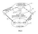
- FIG. 3is a block diagram illustrating a second example embodiment wherein the IP control plane and the session control plane have been brought together
- FIG. 4is a block diagram illustrating registration of middleboxes and packet flows at an midcom agent, the block diagram also illustrating how midcom agents can interwork,
- FIG. 5is a flow diagram of an example method
- FIG. 6is a block diagram illustrating non-desired control layer signalling between domains
- FIG. 7is a block diagram illustrating control layer signalling between domains
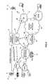
- FIG. 8is a schematic block diagram illustrating an environment in which the technology described herein is used in order to control mobile packet flows.
- FIG. 2A first non-limiting, example embodiment is shown in FIG. 2 .
- the session layer and session signallingis the same as in FIG. 1 .
- the IP layer 5is divided into an IP control plane 4 and a user data plane 6 and the IP control signalling path is made independent of the user data path.
- the IP control signalling path on the IP control planewill follow the IP control signalling path illustrated by the double headed arrow 9 .
- the IP layer 6is correspondingly changed and will transport user data on the IP user data plane.
- a user data flowis shown with broad arrows 10 and passes middleboxes 13 , 14 and a plurality of other nodes schematically shown at NO on its way between terminals 1 and 3 .
- a midcom agent 15is arranged at the IP control plane and controls the middleboxes.
- the midcom agentcomprises control functions for the middleboxes it controls and provides control orders relating to how the middleboxes shall handle an individual flow. These functions relate to resource management, resource control, QoS control, firewalls, network address translators, etc.
- the control functionare performed according to the session parameters for bandwidth and QoS that are negotiated using the session layer signalling protocol.
- This combined flow and middlebox registrationis schematically shown at vertical arrow 16 .
- the midcomsearches for the functions related to the individual flow and when these are found the midcom agent sends a corresponding flow control message or messages to the reporting middlebox.
- This flow controlis schematically shown at vertical arrow 17 .
- the midcom working grouphas investigated protocols to be used as signalling protocols between middleboxes and a midcom agent and have found a couple of candidates, among these the standard Common Open Policy Service (COPS) protocol and the Simple Network Management Protocol (SNMP). None of these suggested midcom protocols, however, support flow registration in accordance with the technology described herein. Instead, the existing midcom protocols are complemented with information elements required for supporting flow registration and flow control, and the protocols so complemented will for reasons of simplicity be referred to as extended midcom protocols. With regard to FIG. 2 , the extended midcom protocol represents vertical signalling, while control signalling at the IP control plane 4 represents horizontal signalling.
- COPSCommon Open Policy Service
- SNMPSimple Network Management Protocol
- control signallingtakes place stepwise from node to node. In each node the control messages are processed, slowing down the overall signalling.
- FIG. 2the number of processing units in series are smaller, just one (1) in the most favourable case. The vertical signalling is the reason why the signalling is quicker.
- a similar registration procedure at the midcom agenttakes place at each middlebox and node the flow traverses from source to destination. It is thus clear that once the registration has been made, the midcom agent can control the flow that initiated the registration.
- An example of a flow control activity in case the middlebox is a firewallis that it shall open up for a flow specified by the midcom agent.
- the master-slave relationis used to allow the midcom agent to exercise control of the flow specific state machines in the middleboxes.
- the slave, a middleboxregisters with the master, the midcom agent.
- IP layeris divided into an IP control plane and a user data plane.
- a packet marking mechanismwhich differentiates control packets from user packets as will be described in connection with FIG. 6 .
- FIG. 3a second non-limiting, example embodiment is shown, where the IP control plane 4 is separated from the user data path like in the first non-limiting. example embodiment, but this time the IP control plane and its control nodes, the midcom agent inclusive, is co-located with the session layer and its session control node 2 . Also in this embodiment the user data flows register at the middleboxes and nodes they traverse and middleboxes in their turn register at the midcom agent. The user data flow is indicated with the bold double headed arrow 10 while the combined session layer and IP control signalling is indicated with the bold dot-dashed double headed arrow 18 .
- a main advantage with the non-limiting, example embodiment in. FIG. 3is that a single common session and IP control layer signalling protocol can be used, thus reducing the number of signalling protocols and the overhead signalling taking place if a separate session protocol and a separate IP control layer signalling protocol are used.
- the common session and IP signalling protocolbears all information elements needed for the different functions and for the set up of network resources. Since the midcom agent interacts with many different networks that may use many different technologies the common signalling protocol is network independent and contains information elements that are so. The information elements contain sufficient information to translate from various local conditions. As an example consider reservation of bandwidth. Certain networks define bandwidth as peak rate bandwidth while other networks define it as the mean bandwidth.
- FIG. 4illustrates in more detail how the signalling between the user terminals 1 and 3 takes place on different planes in accordance with the first non-limiting, example embodiment.
- a flow registration procedurewill be described with reference to the flow diagram of FIG. 5 .
- each user terminalis shown to comprise an application 19 , an application program interface API, an IP layer control 20 on the IP control plane, and the IP user data plane 6 .
- Midcom agent 15serves middleboxes 13 , 14 which are connected to different non-shown networks.
- the middleboxes and nodes controlled by the midcom agent 15 and the networks said middleboxesare connected to form a first domain 22 .
- Midcom agent 21serves middleboxes 23 , 24 which are connected to non-shown other networks, different from those in the first domain.
- the middleboxes and nodes controlled by midcom agent 21 and the networks theyare connected to form a second domain 25 .
- the IP layer control 20signals on the control plane to midcom agents in order to reserve control plane resources for a forthcoming specified user data flow. This is done in order to initiate the control plane and is indicated with the double headed arrow 26 .
- the midcom agentssend announcements to all middleboxes in its domain as is illustrated by arrow 27 .
- the midcom agentannounces its presence to the middleboxes so that the middleboxes shall know the entity to which they shall send their registration messages.
- the middlebox or nodesends (1) a middlebox registration message 28 to the midcom agent and (2) a user data flow registration message 29 to the midcom agent.
- the midcom agentsends a control message 30 to the middlebox, said control message comprising instructions how the flow shall be processed and/or handled by the middlebox.
- arrows 27 - 30are individually shown at middlebox 24 , while they are collectively shown as a single double headed arrow at the rest of the middleboxes.
- Flow registrationis described in more detail in FIG. 5 .
- the session signalling terminal 1negotiates with the session controller and the session controller assigns a flow identity FID to the requested communication, step 31 .
- the control planeis initiated for the specific flow. This is done by initiating a control process, step 32 , in the midcom agent, said control process among other things controlling the bandwidth agreed upon during the session signalling.
- step 32the control process
- step 33the user data flow at user terminal 1 starts, step 33 in the flow diagram.
- the middleboxexamines the incoming flow in order to establish its identity, for example by reading the source and destination address and possibly also port number in the headers of the incoming packets.
- the middleboxfinds the address of the midcom agent and sends a middlebox registration message to the midcom agent, said message containing the identity of the middlebox and its functional capabilities, step 28 corresponding to arrow 28 in FIG. 4 .
- step 29that corresponds to arrow 29 in FIG. 4 the middlebox sends a flow registration message for the flow to the midcom agent which optionally in its turn may forward it to the session controller.
- the flow identity FIDis also used in the IP control plane signalling; the IP control plane matches the flow identity in the session signalling with the flow identity FID in the flow registration message and finds the middlebox functionality to be used for the identified flow, step 34 .
- the midcom agentfinds the control process to be used for the identified flow at the identified middlebox, step 35 .
- the midcom agentsends a control message to the middlebox that registered, step 30 corresponding to arrow 30 , so that this can process the flow correctly.
- Such control messages sent by the midcom agentare part of the extended midcom protocol.
- Midcom agent 15handles the part of the flow in domain 22 and midcom agent 21 handles the part of the same flow in domain 25 .
- midcom agent 21handles the part of the same flow in domain 25 .
- the midcom agentcan send flow control messages to several or all middleboxes and other nodes along the path of the IP flow. In a mobile multi-access scenario, some of these nodes may enter or leave the path of the flow during the lifetime of a session.
- FIG. 6illustrates a system comprising several domains, each one represented by the cloud network symbol. Each domain has an ingress middlebox, an egress middlebox, a midcom agent and a plurality of non-shown other middleboxes and nodes.
- FIG. 6is used to demonstrate a problem that may arise when the user data and control plans are separated. User A and B communicate. User data follow a user data path at the user data plane 6 while routing tables may have indicated that control data shall follow the control signalling path 9 because this path is shorter as seen from a control plane view. This has the consequence that the midcom agent in the bottommost domain receives no control data and therefore cannot control the user data flow therein. In order to avoid this any of the procedures described in FIG. 7 is used.
- FIG. 7illustrates IP control layer signalling in general and IP control layer signalling over domains in particular.
- a domainconsists of the middleboxes that are controlled by one midcom agent. Therefore a domain may also be referred to as a midcom domain.
- the IP control layer signalling messagesmust be routed through the same domains as the user data. Moreover, the signalling must be routed through the specific midcom agents that have, or are able to, set up a control session with the middleboxes that the associated user data flow traverses. This can be achieved using the procedure described below (action numeration refers to correspondingly numerated arrows in FIG. 7 ):
- edge middleboxWhen a signalling message arrives at the edge of a midcom domain the edge middlebox, ingress middlebox IN in the drawing, filters the signalling message and tunnels it to the midcom agent 15 , arrow 36 .
- the midcom agent 15processes the signalling message and forwards it according to one of the following alternatives:
- Each ingress middleboxis configured to forward the signalling messages to the midcom agent of the domain.
- IP control plane Separation of the IP control plane from the IP user data planeis made by having the middlebox to analyse each incoming packets with regard to flow identity and packet type, that is whether the packet is a user data packet or a control packet. This information is read from the header of the packet. Control packets are filtered out and tunnelled to the midcom agent.
- the user data flowis illustrated with the bold arrow 6
- the IP control signallingis illustrated with the thin arrows 9 , 36 , 37 A-B.
- the respective midcom agentmay perform an address translation to either the ingress or egress middlebox. Ingress and egress refers to the middleboxes at which a specific user flow and its related control flow enters and exits respectively a midcom domain.
- FIG. 8a possible scenario is illustrated wherein the middlebox registration process in accordance with the invention is used.
- a userhas a wireless personal access network, PAN, 38 to which for example a cellular telephone 39 and a digital camera 40 is connected.
- a middlebox 13is connected to the network 38 .
- the useris onboard a moving vehicle 41 that has an onboard wireless IP based network 42 to which another middlebox 43 is connected.
- the middlebox 43communicates with a non-shown middlebox connected to a 4G wireless access network 44 , which in its turn is connected to an IP based multi network (backbone network) 45 .
- a middlebox 46is connected to the 4G network.
- Terminal 3 of user Bin this case B's cellular telephone, is connected to B's access network, a 3G wireless network 47 to which a middlebox 48 is connected.
- the middleboxescan signal to a midcom agent 15 using the extended midcom protocol.
- the session controller 2allows set up of communication between the shown networks.
- User Awants to have a telephone conversation with user B and sends a corresponding request to the session controller, which then sets up a path between A and B in the networks 38 , 42 , 44 , 45 and 47 in accordance with the principle discussed above.
- This pathcomprises multiple radio hops and a moving network 42 which changes access networks as the vehicle moves in the landscape.
Landscapes
- Engineering & Computer Science (AREA)
- Computer Networks & Wireless Communication (AREA)
- Signal Processing (AREA)
- Multimedia (AREA)
- Business, Economics & Management (AREA)
- General Business, Economics & Management (AREA)
- Computer Hardware Design (AREA)
- Computer Security & Cryptography (AREA)
- Computing Systems (AREA)
- General Engineering & Computer Science (AREA)
- Data Exchanges In Wide-Area Networks (AREA)
- Mobile Radio Communication Systems (AREA)
Abstract
Description
- alternative a: If the midcom agent has a routing map of its domain, it analyses the destination address of the signalling message and forwards it to the egress middlebox EN,
arrow 37A, thereby ensuring that user data and control data exit the domain in one and the same node EN. - alternative b: If the midcom agent does not have a routing map of its domain, it returns the signalling message to the ingress middlebox IN, which forwards it along the same path as the user data,
arrow 37B, in which case the routing protocol will send user data and control data to the egress middlebox.
- alternative a: If the midcom agent has a routing map of its domain, it analyses the destination address of the signalling message and forwards it to the egress middlebox EN,
- [1] RFC 3303 “Middlebox communication architecture and framework”.
- [2] RFC 3304 “Middlebox communications (Midcom) Protocol Requirements”.
- [3] 3GPP specification 23.207: End-to-end QoS Concepts and Architecture, rev. 5.8.0.
- [4] RFC 2748: The COPS (Common Open Policy Service) Protocol.
Claims (20)
Priority Applications (1)
| Application Number | Priority Date | Filing Date | Title |
|---|---|---|---|
| US10/583,962US8155116B2 (en) | 2003-12-22 | 2004-02-27 | Control of mobile packet streams |
Applications Claiming Priority (3)
| Application Number | Priority Date | Filing Date | Title |
|---|---|---|---|
| US53090403P | 2003-12-22 | 2003-12-22 | |
| US10/583,962US8155116B2 (en) | 2003-12-22 | 2004-02-27 | Control of mobile packet streams |
| PCT/SE2004/000265WO2005062558A1 (en) | 2003-12-22 | 2004-02-27 | Control of mobile packet streams |
Publications (2)
| Publication Number | Publication Date |
|---|---|
| US20070286185A1 US20070286185A1 (en) | 2007-12-13 |
| US8155116B2true US8155116B2 (en) | 2012-04-10 |
Family
ID=34710185
Family Applications (1)
| Application Number | Title | Priority Date | Filing Date |
|---|---|---|---|
| US10/583,962Expired - Fee RelatedUS8155116B2 (en) | 2003-12-22 | 2004-02-27 | Control of mobile packet streams |
Country Status (5)
| Country | Link |
|---|---|
| US (1) | US8155116B2 (en) |
| EP (1) | EP1698118B1 (en) |
| CN (1) | CN1898917B (en) |
| ES (1) | ES2388667T3 (en) |
| WO (1) | WO2005062558A1 (en) |
Cited By (6)
| Publication number | Priority date | Publication date | Assignee | Title |
|---|---|---|---|---|
| US20090310614A1 (en)* | 2008-06-13 | 2009-12-17 | Cisco Technology, Inc. | System and Method for Establishment of a Multiprotocol Label Switching (MPLS) Tunnel |
| US20110256875A1 (en)* | 2010-04-14 | 2011-10-20 | Qualcomm Incorporated | Method and apparatus for supporting location services via a home node b (hnb) |
| US20130250783A1 (en)* | 2012-03-26 | 2013-09-26 | Harris Corporation | Systems and methods registration and maintenance of wireless clients via a proxy wireless network service |
| US20140068602A1 (en)* | 2012-09-04 | 2014-03-06 | Aaron Robert Gember | Cloud-Based Middlebox Management System |
| US10383166B2 (en) | 2010-04-14 | 2019-08-13 | Qualcomm Incorporated | Method and apparatus for supporting location services via a home node B (HNB) |
| US11895177B2 (en) | 2016-09-30 | 2024-02-06 | Wisconsin Alumni Research Foundation | State extractor for middlebox management system |
Families Citing this family (56)
| Publication number | Priority date | Publication date | Assignee | Title |
|---|---|---|---|---|
| DE10353925B4 (en)* | 2003-11-18 | 2009-12-24 | Nec Europe Ltd. | Procedure for exchanging data between two hosts |
| US8996722B2 (en)* | 2004-11-01 | 2015-03-31 | Alcatel Lucent | Softrouter feature server |
| US20080107124A1 (en)* | 2006-11-06 | 2008-05-08 | Jordi Ros-Giralt | System and method for supporting mobility and multipath packet delivery in ip communications and computer networks across nat and firewall boxes |
| US20100046530A1 (en)* | 2006-12-12 | 2010-02-25 | Jani Hautakorpi | IP Address Distribution in Middleboxes |
| EP2597816B1 (en) | 2007-09-26 | 2019-09-11 | Nicira Inc. | Network operating system for managing and securing networks |
| WO2010116606A1 (en) | 2009-03-30 | 2010-10-14 | 日本電気株式会社 | Communication flow control system, communication flow control method, and communication flow processing program |
| CN102726007B (en) | 2009-04-01 | 2015-04-08 | Nicira股份有限公司 | Method and apparatus for implementing and managing virtual switches |
| US9009293B2 (en) | 2009-11-18 | 2015-04-14 | Cisco Technology, Inc. | System and method for reporting packet characteristics in a network environment |
| US8964528B2 (en) | 2010-07-06 | 2015-02-24 | Nicira, Inc. | Method and apparatus for robust packet distribution among hierarchical managed switching elements |
| US8837493B2 (en) | 2010-07-06 | 2014-09-16 | Nicira, Inc. | Distributed network control apparatus and method |
| US9525647B2 (en) | 2010-07-06 | 2016-12-20 | Nicira, Inc. | Network control apparatus and method for creating and modifying logical switching elements |
| US10103939B2 (en) | 2010-07-06 | 2018-10-16 | Nicira, Inc. | Network control apparatus and method for populating logical datapath sets |
| US9680750B2 (en) | 2010-07-06 | 2017-06-13 | Nicira, Inc. | Use of tunnels to hide network addresses |
| US8787303B2 (en) | 2010-10-05 | 2014-07-22 | Cisco Technology, Inc. | Methods and apparatus for data traffic offloading at a router |
| US9003057B2 (en)* | 2011-01-04 | 2015-04-07 | Cisco Technology, Inc. | System and method for exchanging information in a mobile wireless network environment |
| US9043452B2 (en) | 2011-05-04 | 2015-05-26 | Nicira, Inc. | Network control apparatus and method for port isolation |
| US8948013B1 (en) | 2011-06-14 | 2015-02-03 | Cisco Technology, Inc. | Selective packet sequence acceleration in a network environment |
| AU2012296329B2 (en) | 2011-08-17 | 2015-08-27 | Nicira, Inc. | Logical L3 routing |
| US9137052B2 (en) | 2011-08-17 | 2015-09-15 | Nicira, Inc. | Federating interconnection switching element network to two or more levels |
| US9178833B2 (en) | 2011-10-25 | 2015-11-03 | Nicira, Inc. | Chassis controller |
| AU2015258160B2 (en)* | 2011-11-15 | 2017-04-20 | VMware LLC | Network control system for configuring middleboxes |
| US9172603B2 (en)* | 2011-11-15 | 2015-10-27 | Nicira, Inc. | WAN optimizer for logical networks |
| US9838308B2 (en)* | 2011-12-28 | 2017-12-05 | Futurewei Technologies, Inc. | Improving the architecture of middleboxes or service routers to better consolidate diverse functions |
| EP2955886B1 (en) | 2012-04-18 | 2020-05-06 | Nicira Inc. | Using transactions to compute and propagate network forwarding state |
| US9787570B2 (en)* | 2012-10-17 | 2017-10-10 | Verizon Patent And Licensing Inc. | Dynamic feature peer network for application flows |
| US9571386B2 (en) | 2013-07-08 | 2017-02-14 | Nicira, Inc. | Hybrid packet processing |
| US9407580B2 (en) | 2013-07-12 | 2016-08-02 | Nicira, Inc. | Maintaining data stored with a packet |
| US9344349B2 (en) | 2013-07-12 | 2016-05-17 | Nicira, Inc. | Tracing network packets by a cluster of network controllers |
| US9282019B2 (en) | 2013-07-12 | 2016-03-08 | Nicira, Inc. | Tracing logical network packets through physical network |
| US9602398B2 (en) | 2013-09-15 | 2017-03-21 | Nicira, Inc. | Dynamically generating flows with wildcard fields |
| US9674087B2 (en) | 2013-09-15 | 2017-06-06 | Nicira, Inc. | Performing a multi-stage lookup to classify packets |
| US9967199B2 (en) | 2013-12-09 | 2018-05-08 | Nicira, Inc. | Inspecting operations of a machine to detect elephant flows |
| US10193771B2 (en) | 2013-12-09 | 2019-01-29 | Nicira, Inc. | Detecting and handling elephant flows |
| US9996467B2 (en) | 2013-12-13 | 2018-06-12 | Nicira, Inc. | Dynamically adjusting the number of flows allowed in a flow table cache |
| US9569368B2 (en) | 2013-12-13 | 2017-02-14 | Nicira, Inc. | Installing and managing flows in a flow table cache |
| US8989199B1 (en)* | 2014-02-24 | 2015-03-24 | Level 3 Communications, Llc | Control device discovery in networks having separate control and forwarding devices |
| US9385954B2 (en) | 2014-03-31 | 2016-07-05 | Nicira, Inc. | Hashing techniques for use in a network environment |
| US9985896B2 (en) | 2014-03-31 | 2018-05-29 | Nicira, Inc. | Caching of service decisions |
| US10193806B2 (en) | 2014-03-31 | 2019-01-29 | Nicira, Inc. | Performing a finishing operation to improve the quality of a resulting hash |
| US11178051B2 (en) | 2014-09-30 | 2021-11-16 | Vmware, Inc. | Packet key parser for flow-based forwarding elements |
| US10469342B2 (en) | 2014-10-10 | 2019-11-05 | Nicira, Inc. | Logical network traffic analysis |
| US9967134B2 (en) | 2015-04-06 | 2018-05-08 | Nicira, Inc. | Reduction of network churn based on differences in input state |
| US10204122B2 (en) | 2015-09-30 | 2019-02-12 | Nicira, Inc. | Implementing an interface between tuple and message-driven control entities |
| US11019167B2 (en) | 2016-04-29 | 2021-05-25 | Nicira, Inc. | Management of update queues for network controller |
| US10243845B2 (en) | 2016-06-02 | 2019-03-26 | International Business Machines Corporation | Middlebox tracing in software defined networks |
| US10805239B2 (en) | 2017-03-07 | 2020-10-13 | Nicira, Inc. | Visualization of path between logical network endpoints |
| US10608887B2 (en) | 2017-10-06 | 2020-03-31 | Nicira, Inc. | Using packet tracing tool to automatically execute packet capture operations |
| US11283699B2 (en) | 2020-01-17 | 2022-03-22 | Vmware, Inc. | Practical overlay network latency measurement in datacenter |
| US11558426B2 (en) | 2020-07-29 | 2023-01-17 | Vmware, Inc. | Connection tracking for container cluster |
| US11570090B2 (en) | 2020-07-29 | 2023-01-31 | Vmware, Inc. | Flow tracing operation in container cluster |
| US11196628B1 (en) | 2020-07-29 | 2021-12-07 | Vmware, Inc. | Monitoring container clusters |
| US11736436B2 (en) | 2020-12-31 | 2023-08-22 | Vmware, Inc. | Identifying routes with indirect addressing in a datacenter |
| US11336533B1 (en) | 2021-01-08 | 2022-05-17 | Vmware, Inc. | Network visualization of correlations between logical elements and associated physical elements |
| US11687210B2 (en) | 2021-07-05 | 2023-06-27 | Vmware, Inc. | Criteria-based expansion of group nodes in a network topology visualization |
| US11711278B2 (en) | 2021-07-24 | 2023-07-25 | Vmware, Inc. | Visualization of flow trace operation across multiple sites |
| US11706109B2 (en) | 2021-09-17 | 2023-07-18 | Vmware, Inc. | Performance of traffic monitoring actions |
Citations (17)
| Publication number | Priority date | Publication date | Assignee | Title |
|---|---|---|---|---|
| US20010021176A1 (en)* | 2000-03-13 | 2001-09-13 | Itaru Mimura | Method of monitoring quality of communication for each flow |
| US6507873B1 (en)* | 1998-07-08 | 2003-01-14 | Nec Corporation | Network address assigning system |
| US20030093481A1 (en)* | 2001-11-09 | 2003-05-15 | Julian Mitchell | Middlebox control |
| US20030123388A1 (en) | 2001-12-28 | 2003-07-03 | Patrick Bradd | Admissions control in a connectionless communications network |
| US6628655B1 (en)* | 1999-02-26 | 2003-09-30 | International Business Machines Corporation | Method of self-learning for the switching nodes of a data transmission network |
| US20030206546A1 (en)* | 2002-05-01 | 2003-11-06 | Beyda William J. | System and method for automatic voice over IP endpoint configuration |
| US20030214945A1 (en)* | 2002-05-20 | 2003-11-20 | Hidetoshi Kawamura | Packet switch and method of forwarding packet |
| US6795857B1 (en)* | 1999-06-15 | 2004-09-21 | Cisco Technology, Inc. | Methods and apparatus for providing mobility of a node that does not support mobility |
| US20040205245A1 (en)* | 2003-03-28 | 2004-10-14 | Jean-Francois Le Pennec | Data transmission system with a mechanism enabling any application to run transparently over a network address translation device |
| US20040203765A1 (en)* | 2002-06-27 | 2004-10-14 | Kaustubh Das | Continuous mobility across wireless networks by integrating mobile IP and GPRS mobility agents |
| US7359350B2 (en)* | 1999-02-19 | 2008-04-15 | Fujitsu Limited | Mobile packet communication system |
| US7366524B2 (en)* | 2002-02-06 | 2008-04-29 | Ntt Docomo Inc. | Using subnet relations for paging, authentication, association and to activate network interfaces in heterogeneous access networks |
| US7420943B2 (en)* | 2001-12-06 | 2008-09-02 | Nokia Corporation | Mechanism to create pinhole for existing session in middlebox |
| US7437145B2 (en)* | 2004-12-01 | 2008-10-14 | Canon Kabushiki Kaisha | Wireless control apparatus, system, control method, and program |
| US7477648B2 (en)* | 2004-09-17 | 2009-01-13 | Hitachi Communication Technologies, Ltd. | Packet forwarding apparatus and access network system |
| US20090040995A1 (en)* | 2003-07-14 | 2009-02-12 | Buddhikot Milind M | Method and system for mobility across heterogeneous address spaces |
| US7580401B2 (en)* | 2003-10-22 | 2009-08-25 | Nortel Networks Limited | Method and apparatus for performing routing operations in a communications network |
- 2004
- 2004-02-27USUS10/583,962patent/US8155116B2/ennot_activeExpired - Fee Related
- 2004-02-27EPEP04715612Apatent/EP1698118B1/ennot_activeExpired - Lifetime
- 2004-02-27CNCN2004800382937Apatent/CN1898917B/ennot_activeExpired - Fee Related
- 2004-02-27ESES04715612Tpatent/ES2388667T3/ennot_activeExpired - Lifetime
- 2004-02-27WOPCT/SE2004/000265patent/WO2005062558A1/enactiveApplication Filing
Patent Citations (18)
| Publication number | Priority date | Publication date | Assignee | Title |
|---|---|---|---|---|
| US6507873B1 (en)* | 1998-07-08 | 2003-01-14 | Nec Corporation | Network address assigning system |
| US7359350B2 (en)* | 1999-02-19 | 2008-04-15 | Fujitsu Limited | Mobile packet communication system |
| US6628655B1 (en)* | 1999-02-26 | 2003-09-30 | International Business Machines Corporation | Method of self-learning for the switching nodes of a data transmission network |
| US6795857B1 (en)* | 1999-06-15 | 2004-09-21 | Cisco Technology, Inc. | Methods and apparatus for providing mobility of a node that does not support mobility |
| US20010021176A1 (en)* | 2000-03-13 | 2001-09-13 | Itaru Mimura | Method of monitoring quality of communication for each flow |
| US20030093481A1 (en)* | 2001-11-09 | 2003-05-15 | Julian Mitchell | Middlebox control |
| EP1315359A2 (en) | 2001-11-09 | 2003-05-28 | Nortel Networks Limited | A method for controling a Middlebox |
| US7420943B2 (en)* | 2001-12-06 | 2008-09-02 | Nokia Corporation | Mechanism to create pinhole for existing session in middlebox |
| US20030123388A1 (en) | 2001-12-28 | 2003-07-03 | Patrick Bradd | Admissions control in a connectionless communications network |
| US7366524B2 (en)* | 2002-02-06 | 2008-04-29 | Ntt Docomo Inc. | Using subnet relations for paging, authentication, association and to activate network interfaces in heterogeneous access networks |
| US20030206546A1 (en)* | 2002-05-01 | 2003-11-06 | Beyda William J. | System and method for automatic voice over IP endpoint configuration |
| US20030214945A1 (en)* | 2002-05-20 | 2003-11-20 | Hidetoshi Kawamura | Packet switch and method of forwarding packet |
| US20040203765A1 (en)* | 2002-06-27 | 2004-10-14 | Kaustubh Das | Continuous mobility across wireless networks by integrating mobile IP and GPRS mobility agents |
| US20040205245A1 (en)* | 2003-03-28 | 2004-10-14 | Jean-Francois Le Pennec | Data transmission system with a mechanism enabling any application to run transparently over a network address translation device |
| US20090040995A1 (en)* | 2003-07-14 | 2009-02-12 | Buddhikot Milind M | Method and system for mobility across heterogeneous address spaces |
| US7580401B2 (en)* | 2003-10-22 | 2009-08-25 | Nortel Networks Limited | Method and apparatus for performing routing operations in a communications network |
| US7477648B2 (en)* | 2004-09-17 | 2009-01-13 | Hitachi Communication Technologies, Ltd. | Packet forwarding apparatus and access network system |
| US7437145B2 (en)* | 2004-12-01 | 2008-10-14 | Canon Kabushiki Kaisha | Wireless control apparatus, system, control method, and program |
Non-Patent Citations (2)
| Title |
|---|
| International Search Report for PCT/SE2004/000265 dated Oct. 1, 2004. |
| Network Working Group, Request for Comments: 3304, Aug. 2002, retrieved on Sep. 30, 2004 from the Internet: www.etsi.org. |
Cited By (11)
| Publication number | Priority date | Publication date | Assignee | Title |
|---|---|---|---|---|
| US20090310614A1 (en)* | 2008-06-13 | 2009-12-17 | Cisco Technology, Inc. | System and Method for Establishment of a Multiprotocol Label Switching (MPLS) Tunnel |
| US8493984B2 (en) | 2008-06-13 | 2013-07-23 | Cisco Technology, Inc. | System and method for establishment of a multiprotocol label switching (MPLS) tunnel |
| US20110256875A1 (en)* | 2010-04-14 | 2011-10-20 | Qualcomm Incorporated | Method and apparatus for supporting location services via a home node b (hnb) |
| US9119028B2 (en)* | 2010-04-14 | 2015-08-25 | Qualcomm Incorporated | Method and apparatus for supporting location services via a Home Node B (HNB) |
| US9681262B2 (en) | 2010-04-14 | 2017-06-13 | Qualcomm Incorporated | Method and apparatus for supporting location services via a home node B (HNB) |
| US10383166B2 (en) | 2010-04-14 | 2019-08-13 | Qualcomm Incorporated | Method and apparatus for supporting location services via a home node B (HNB) |
| US20130250783A1 (en)* | 2012-03-26 | 2013-09-26 | Harris Corporation | Systems and methods registration and maintenance of wireless clients via a proxy wireless network service |
| US9295020B2 (en)* | 2012-03-26 | 2016-03-22 | Harris Corporation | Systems and methods registration and maintenance of wireless clients via a proxy wireless network service |
| US20140068602A1 (en)* | 2012-09-04 | 2014-03-06 | Aaron Robert Gember | Cloud-Based Middlebox Management System |
| US9104492B2 (en)* | 2012-09-04 | 2015-08-11 | Wisconsin Alumni Research Foundation | Cloud-based middlebox management system |
| US11895177B2 (en) | 2016-09-30 | 2024-02-06 | Wisconsin Alumni Research Foundation | State extractor for middlebox management system |
Also Published As
| Publication number | Publication date |
|---|---|
| WO2005062558A1 (en) | 2005-07-07 |
| CN1898917A (en) | 2007-01-17 |
| ES2388667T3 (en) | 2012-10-17 |
| CN1898917B (en) | 2011-06-08 |
| EP1698118B1 (en) | 2012-06-13 |
| US20070286185A1 (en) | 2007-12-13 |
| EP1698118A1 (en) | 2006-09-06 |
Similar Documents
| Publication | Publication Date | Title |
|---|---|---|
| US8155116B2 (en) | Control of mobile packet streams | |
| CN112640372B (en) | Method, system and computer readable medium for providing mobile device connectivity | |
| US11894937B2 (en) | Local user plane function control | |
| US9615318B2 (en) | Multiplexing core networks in RAN sharing | |
| CN101160886B (en) | IP intercommunication gateway and method for implementing IP field intercommunication in next generation network | |
| EP1449341B1 (en) | Policy co-ordination in a communications network | |
| EP1816789B1 (en) | A method and system for controlling the selection of the transmitting path for the media flow in the next generation network | |
| US20220377043A1 (en) | Enabling nat for user plane traffic | |
| EP2071775A1 (en) | Data access | |
| KR20140102398A (en) | Method for sharing network based on software defined network to support multiple operator | |
| EP1820318B1 (en) | A method for identifying real-time traffic hop by hop in an internet network | |
| EP2719147B1 (en) | Communication system and corresponding method for establishing a real-time communication session | |
| Salkintzis et al. | Multipath quic for access traffic steering switching and splitting in 5g advanced | |
| CN102170394B (en) | Method and apparatus for message forwarding | |
| CN101022461A (en) | Method for transmitting signalling information and signalling equipment | |
| US20040052256A1 (en) | Method for transmitting data packets in a cellular communication network | |
| JP2006186855A (en) | Bandwidth securing and route setting method in IP network | |
| WO2005048527A1 (en) | A METHOD OF QoS CONTROL IMPLEMENTED TO TRAFFIC AND A STRATEGY SWITCH APPARATUS | |
| US9426186B2 (en) | Methods and systems for load balancing call sessions over a dual ring internet protocol (IP) network | |
| CN112910791B (en) | Diversion system and method thereof | |
| CN120499664B (en) | Intelligent gateway method and system based on wireless network voice service quality assurance | |
| Ito et al. | Mechanism of reducing signaling processing load in epc/ims using service-specific network virtualization | |
| EP4329374A1 (en) | Communication processing method and related device | |
| WO2012084626A1 (en) | Method for inter-domain communications | |
| CN120499664A (en) | Intelligent gateway method and system based on wireless network voice service quality assurance |
Legal Events
| Date | Code | Title | Description |
|---|---|---|---|
| AS | Assignment | Owner name:TELEFONAKTIEBOLAGET LM ERICSSON (PUBL), SWEDEN Free format text:ASSIGNMENT OF ASSIGNORS INTEREST;ASSIGNORS:FODOR, GABOR;ERIKSSON, ANDERS;REEL/FRAME:019264/0851 Effective date:20060810 | |
| STCF | Information on status: patent grant | Free format text:PATENTED CASE | |
| CC | Certificate of correction | ||
| AS | Assignment | Owner name:HIGHBRIDGE PRINCIPAL STRATEGIES, LLC, AS COLLATERA Free format text:LIEN;ASSIGNOR:OPTIS WIRELESS TECHNOLOGY, LLC;REEL/FRAME:032180/0115 Effective date:20140116 | |
| AS | Assignment | Owner name:OPTIS WIRELESS TECHNOLOGY, LLC, TEXAS Free format text:ASSIGNMENT OF ASSIGNORS INTEREST;ASSIGNOR:CLUSTER, LLC;REEL/FRAME:032286/0501 Effective date:20140116 Owner name:CLUSTER, LLC, DELAWARE Free format text:ASSIGNMENT OF ASSIGNORS INTEREST;ASSIGNOR:TELEFONAKTIEBOLAGET L M ERICSSON (PUBL);REEL/FRAME:032285/0421 Effective date:20140116 | |
| AS | Assignment | Owner name:WILMINGTON TRUST, NATIONAL ASSOCIATION, MINNESOTA Free format text:SECURITY INTEREST;ASSIGNOR:OPTIS WIRELESS TECHNOLOGY, LLC;REEL/FRAME:032437/0638 Effective date:20140116 | |
| FPAY | Fee payment | Year of fee payment:4 | |
| AS | Assignment | Owner name:OPTIS WIRELESS TECHNOLOGY, LLC, TEXAS Free format text:RELEASE BY SECURED PARTY;ASSIGNOR:HPS INVESTMENT PARTNERS, LLC;REEL/FRAME:039361/0001 Effective date:20160711 | |
| FEPP | Fee payment procedure | Free format text:MAINTENANCE FEE REMINDER MAILED (ORIGINAL EVENT CODE: REM.); ENTITY STATUS OF PATENT OWNER: LARGE ENTITY | |
| LAPS | Lapse for failure to pay maintenance fees | Free format text:PATENT EXPIRED FOR FAILURE TO PAY MAINTENANCE FEES (ORIGINAL EVENT CODE: EXP.); ENTITY STATUS OF PATENT OWNER: LARGE ENTITY | |
| STCH | Information on status: patent discontinuation | Free format text:PATENT EXPIRED DUE TO NONPAYMENT OF MAINTENANCE FEES UNDER 37 CFR 1.362 | |
| FP | Lapsed due to failure to pay maintenance fee | Effective date:20200410 |