US8155105B2 - Spread spectrum wireless communication and monitoring arrangement and method - Google Patents
Spread spectrum wireless communication and monitoring arrangement and methodDownload PDFInfo
- Publication number
- US8155105B2 US8155105B2US11/389,674US38967406AUS8155105B2US 8155105 B2US8155105 B2US 8155105B2US 38967406 AUS38967406 AUS 38967406AUS 8155105 B2US8155105 B2US 8155105B2
- Authority
- US
- United States
- Prior art keywords
- monitoring
- central device
- devices
- monitoring devices
- multiple frequencies
- Prior art date
- Legal status (The legal status is an assumption and is not a legal conclusion. Google has not performed a legal analysis and makes no representation as to the accuracy of the status listed.)
- Active, expires
Links
- 230000006854communicationEffects0.000titleclaimsabstractdescription131
- 238000004891communicationMethods0.000titleclaimsabstractdescription131
- 238000012544monitoring processMethods0.000titleclaimsabstractdescription68
- 238000000034methodMethods0.000titleclaimsabstractdescription51
- 238000001228spectrumMethods0.000titleclaimsdescription7
- 238000012806monitoring deviceMethods0.000claimsabstractdescription162
- 230000000694effectsEffects0.000claimsabstractdescription19
- 230000005540biological transmissionEffects0.000claimsdescription68
- 230000033001locomotionEffects0.000claimsdescription58
- 230000004913activationEffects0.000claimsdescription20
- 230000004044responseEffects0.000claimsdescription12
- 238000001514detection methodMethods0.000claimsdescription10
- 238000009434installationMethods0.000claimsdescription8
- 230000000116mitigating effectEffects0.000claimsdescription7
- 230000008569processEffects0.000claimsdescription6
- 230000000737periodic effectEffects0.000claimsdescription2
- 230000002457bidirectional effectEffects0.000claims1
- 108091006146ChannelsProteins0.000description78
- 230000006870functionEffects0.000description16
- 230000009467reductionEffects0.000description10
- 238000012546transferMethods0.000description10
- 238000012545processingMethods0.000description8
- 238000001454recorded imageMethods0.000description6
- 230000006835compressionEffects0.000description4
- 238000013500data storageMethods0.000description4
- 230000003111delayed effectEffects0.000description4
- 230000002093peripheral effectEffects0.000description4
- 238000007906compressionMethods0.000description3
- 230000007423decreaseEffects0.000description3
- 230000001934delayEffects0.000description3
- 238000010586diagramMethods0.000description3
- 238000011156evaluationMethods0.000description3
- 230000001960triggered effectEffects0.000description3
- 230000009471actionEffects0.000description2
- 238000013459approachMethods0.000description2
- 230000006399behaviorEffects0.000description2
- 230000008901benefitEffects0.000description2
- 230000008859changeEffects0.000description2
- 238000012986modificationMethods0.000description2
- 230000004048modificationEffects0.000description2
- 241001465754MetazoaSpecies0.000description1
- 102100040160Rabankyrin-5Human genes0.000description1
- 101710086049Rabankyrin-5Proteins0.000description1
- 230000003213activating effectEffects0.000description1
- 230000002411adverseEffects0.000description1
- 230000003321amplificationEffects0.000description1
- 230000007175bidirectional communicationEffects0.000description1
- 230000033228biological regulationEffects0.000description1
- 238000004364calculation methodMethods0.000description1
- 230000001413cellular effectEffects0.000description1
- 238000013144data compressionMethods0.000description1
- 230000003247decreasing effectEffects0.000description1
- 238000011161developmentMethods0.000description1
- 230000018109developmental processEffects0.000description1
- 230000004438eyesightEffects0.000description1
- 230000006872improvementEffects0.000description1
- 230000000977initiatory effectEffects0.000description1
- 238000012423maintenanceMethods0.000description1
- 238000005259measurementMethods0.000description1
- 238000003199nucleic acid amplification methodMethods0.000description1
- 238000011084recoveryMethods0.000description1
- 238000012552reviewMethods0.000description1
- 238000010187selection methodMethods0.000description1
- 230000008054signal transmissionEffects0.000description1
- 230000001360synchronised effectEffects0.000description1
Images


Classifications
- H—ELECTRICITY
- H04—ELECTRIC COMMUNICATION TECHNIQUE
- H04W—WIRELESS COMMUNICATION NETWORKS
- H04W52/00—Power management, e.g. Transmission Power Control [TPC] or power classes
- H04W52/02—Power saving arrangements
- H04W52/0209—Power saving arrangements in terminal devices
- H04W52/0261—Power saving arrangements in terminal devices managing power supply demand, e.g. depending on battery level
- H—ELECTRICITY
- H04—ELECTRIC COMMUNICATION TECHNIQUE
- H04W—WIRELESS COMMUNICATION NETWORKS
- H04W24/00—Supervisory, monitoring or testing arrangements
- H04W24/10—Scheduling measurement reports ; Arrangements for measurement reports
- Y—GENERAL TAGGING OF NEW TECHNOLOGICAL DEVELOPMENTS; GENERAL TAGGING OF CROSS-SECTIONAL TECHNOLOGIES SPANNING OVER SEVERAL SECTIONS OF THE IPC; TECHNICAL SUBJECTS COVERED BY FORMER USPC CROSS-REFERENCE ART COLLECTIONS [XRACs] AND DIGESTS
- Y02—TECHNOLOGIES OR APPLICATIONS FOR MITIGATION OR ADAPTATION AGAINST CLIMATE CHANGE
- Y02D—CLIMATE CHANGE MITIGATION TECHNOLOGIES IN INFORMATION AND COMMUNICATION TECHNOLOGIES [ICT], I.E. INFORMATION AND COMMUNICATION TECHNOLOGIES AIMING AT THE REDUCTION OF THEIR OWN ENERGY USE
- Y02D30/00—Reducing energy consumption in communication networks
- Y02D30/70—Reducing energy consumption in communication networks in wireless communication networks
Definitions
- the present inventionis directed to a spread spectrum wireless communication and monitoring arrangement and method that monitors using wireless communication between two devices and, more specifically, to a monitoring arrangement and method that monitors activity using a remote device to report to a central device.
- monitoring devicessuch as cameras, motion sensors, keypads or contact sensors.
- many buildingshave multiple locations that are monitored for security purposes, requiring multiple monitoring devices in the different locations.
- the monitoring devicescan be configured to communicate with one or more central devices.
- the central devicecan, among other things, perform monitoring or recording functions, determine whether the security has been breached and whether to contact security personnel.
- One method of communicating between the monitoring devices and the central deviceis by a physical connection, such as electrical or other wiring.
- a physical connectionsuch as electrical or other wiring.
- Using wiring to establish communication between the security devicescan be troublesome for a number of reasons, such as the high cost of installation and maintenance. For example, exposed wiring is often unacceptable in a building, and thus, the installation of the monitoring system requires passing the wires through the walls of the building. This type of installation can significantly increase the time required to complete a monitoring system installation.
- the use of wirescan limit the functionality of many monitoring systems, such as where it is desirable to have portable monitoring devices.
- wireless monitoring devicesto reduce or eliminate the need for physical connections between the devices, however, wireless monitoring systems also have a set of problems, such as battery life.
- the security deviceswould be self-powered by, for example, a battery.
- Self-powered devicesare more secure because they are not subject to failure upon a loss of power to the building. They also require less installation problems because they do not need to be connected to a separate power source; however, self-powered devices often have reliability issues due to the finite life of their power source.
- Increasing the useable time of a power sourcereduces the cost for replacement of the power source and increases the usefulness of the entire system by having less potential downtime of the system or its components.
- Several recent developmentshave increased the potential power requirements of wireless monitoring devices.
- monitoring devicesthat contain digital cameras require enough power to run the camera, to store the digital picture in memory and to transmit the digital picture to the central device.
- the present inventionis directed to the above and related types of integrated security systems. These and other aspects of the present invention are exemplified in a number of illustrated implementations and applications, some of which are shown in the figures and characterized in the claims section that follows.
- a monitoring systemis implemented for wireless communication between a central device and monitoring devices.
- Each of the devicesincludes a wireless communication circuit to effect wireless communications between the central device and the monitoring devices.
- Communication intervalsthat define communication between at least one of the monitoring devices and the central device are provided along with a selected frequency for communicating between the devices.
- Communicationis established between the devices based on the communication intervals and the selected frequency, and power consumption is reduced in at least one of the devices as a function of the communication intervals and the selected frequency.
- at least one of the devicesrelies on a limited power source, and the central device collects monitoring data from the monitoring devices while mitigating power consumption from the limited power source.
- a methodfor wireless communication between a central device and monitoring devices.
- Each of the devicesincludes a wireless communication circuit to effect wireless communications between the central device and the monitoring devices.
- Communication intervalsthat define communication between at least one of the monitoring devices and the central device are provided along with a selected frequency for communicating between the devices.
- Communicationis established between the monitoring device and the central device using the communications interval and the selected frequency.
- the power consumption of at least one of the wireless communication circuitsis reduced as a function of the communications interval and the selected frequency.
- at least one of the devicesrelies on a limited power source, and the central device collects monitoring data from the monitoring devices while mitigating power consumption from the limited power source.
- a communications protocolis implemented using a receiver which reduces power by limiting its active listening time.
- the receiverlimits the active listening time by coordinating a transmission period and a listening frequency in accordance with the communications protocol.
- a communications protocolis implemented using a transmitter which reduces power by limiting its active transmission time while maintaining equal channel use.
- the transmitterlimits the active transmission time by coordinating a transmission period and a listening frequency in accordance with the communications protocol.
- a communications protocolis implemented using a transceiver which reduces power by limiting its active listening time or its active transmission time by coordinating a transmission period and a listening frequency in accordance with the communications protocol.
- FIG. 1illustrates a monitoring system, according to an example embodiment of the present invention
- FIG. 1Ashows a block diagram of two wireless communication devices, according to another example embodiment of the present invention.
- FIG. 2shows a flow chart for a method of communication between communication devices in a monitoring system, according to another example embodiment of the present invention
- FIG. 3shows an implementation of a transmit anticipation time and frequency-hop table, according to another example embodiment of the present invention.
- FIG. 4is a flow chart for a method of transmitting data, in accordance with another example embodiment of the present invention.
- FIG. 5shows the format of the transmission of short messages, according to another example embodiment of the present invention.
- FIG. 6shows the format of the transmission of long messages, according to another example embodiment of the present invention.
- FIG. 7is a flow diagram of how the motion detection and camera functions of a monitoring device are implemented, according to an example embodiment of the present invention.
- FIG. 8is a flow diagram of generating a monitor system status report, according to an example embodiment of the present invention.
- the present inventionis believed to be applicable to a variety of different approaches and arrangements for providing monitoring services.
- the inventionhas been found to be particularly advantageous for addressing monitoring needs using wireless monitoring devices while reducing the power consumption of the monitoring devices.
- the monitoring devicesinclude image capture devices, motion detection devices and other monitoring methods.
- a motion sensorconfigured with an image capture device can be implemented to report movement and image information for various uses.
- a few examples of such usesinclude, reporting objects hidden from an operator of large machinery or vehicle, reporting pets that enter or leave proscribed areas, reporting security breaches, remote-environment monitoring, reporting criminal activity and reporting unusual driver behavior.
- a monitoring systemprovides monitoring and reporting functions using spread spectrum wireless communications between one or more monitoring devices and a central device for receiving the reporting information from the monitoring devices.
- the monitoring deviceactivates a motion detection circuit in response to a predefined event occurrence.
- the camera arrangement of the monitoring deviceactivates in response to the motion detection circuit sensing or failing to sense movement.
- Each of the devicesincludes a wireless communication circuit to effect wireless communications between the central device and the monitoring devices, and at least one of the devices relies on a limited power source. Power consumption is reduced for at least one of the wireless communication circuits by coordinating a communications time interval and a selected channel for communication between the central device and the monitoring device to effect wireless communications between the central device and said at least one of the monitoring devices.
- the selected channelis one of a sequence of channels used for wireless communications between the central device and the monitoring devices.
- the central devicecollects reporting data from the monitoring devices while mitigating power consumption from the limited power source.
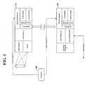
- FIG. 1depicts several elements of monitoring device 110 that may be implemented, including a transceiver block, a message protocol block, a synchronization block and a transmit (Tx) anticipation block.
- a monitoring devicewirelessly transmits a signal using the transceiver block.
- the monitoring deviceuses information regarding a transmission period and the listening channel of the central device during the transmission process.
- the monitoring devicestransmit monitoring information to the central device.
- monitoring device 110might transmit video images or device-status information to the central device.
- FIG. 1depicts central device 160 as including a transceiver block, a message protocol block, a synchronization block and a transmit (Tx) anticipation block.
- the transceiver blockis used for receiving signals from one of the monitoring devices as a function of the communication intervals and the frequency the central device uses to listen for transmissions.
- the listening frequencyis one of several potential frequencies available for communication between the monitoring devices and the central device.
- the systemmay use a number of contiguous frequency slots (channels) within a suitable frequency band.
- One example of such a useincludes 25 or more channels within the ISM frequency band from 902-928 MHz. Numerous other combinations of channels and frequency bands are possible using the present invention.
- the central device and monitoring devicesare implemented using a similar set of elements as depicted by blocks 110 and 160 ; however, various components may be implemented differently.
- the synchronization blockcan be implemented differently in the central device versus the monitoring devices where the central device provides synchronization information to each of the monitoring devices and the monitoring devices must use the synchronization information to maintain synchronization using a local clock.
- the monitoring deviceswould compare the synchronization information with the local clock in order to compensate for any difference between the monitoring devices' time frames and the central device's time frame.
- the synchronization informationcan take the form of a time index, such as a counter value, a current time of day or any other time based data which the monitoring device can use as a reference for synchronization.
- the time indexcan be a reference within each message transmitted.
- the peripheral devicecan compare when the message was received to when the message was expected.
- the peripheral devicemay also be configured to adjust the local clock using a compensation for a timing error. For instance, if the peripheral clock appears to be running slower than the control panel, the peripheral can compensate by increasing the clock frequency or using a counter to compensate for the differences between clocks.
- the central device and the monitoring device blocksare depicted as having a transceiver; however, the system may be implemented using variations of receivers and transmitters. In some instances, a monitoring device may be implemented with only a transmitter. In other instances, a monitoring device may be implemented with only a receiver. Other implementations allow for one or more of the central devices and monitoring devices to have both a transmitter and receiver (transceiver). Thus, transceiver is used herein to describe a receiver, transmitter or both a receiver and transmitter.
- One embodiment of the present inventionreduces the power of one of the devices as a function of the listening channel and a communications period.
- the systemdecreases the length of time that a receiver is active by using the communications period and listening channel to reduce the window of time necessary to receive the start of a transmission.
- various methods of power reductionare employed, such as removing power from the receiving devices or reducing or stopping selected functions (e.g., amplification or processing).
- the synchronizationcan further reduce the active time of the transmitter because, for example, the transmitter may limit the transmission times relative to the times for which the receiver is active. Such a reduction can be accomplished because, for example, in many systems the transmission time cannot be shorter than the Rx activation period of the receiver without knowledge of when the Rx activation occurs; however, synchronization can reduce the transmission times to less than the Rx activation period of the receiver.
- the central devicesends periodic synchronization messages to the monitoring devices.
- a monitoring device that determines it has lost synchronization with the central devicecan increase the active time of the receiver to compensate for the loss in synchronization.
- the devicecan increase the active receive time to ensure that a transmission from the central device will be received.
- the monitoring devicecan increase the activation time based upon an expected accuracy of the local tracking (e.g., local clock) of the central device time-base. For instance, where the expected accuracy of the local tracking is relatively high, the monitoring device increases the activation time only upon the loss of several synchronization messages.
- Some devicessuch as a keyfob or other handheld device, are portable and are often removed from the wireless communication range of the rest of the system or may cease to receive or transmit information in response to a period of inactivity.
- the portable devicesoften lose synchronization during the time they are unable to communicate with the central device.
- Such portable devicesfrequently increase the activation time to compensate for the lack of synchronization between the portable devices and the central device.
- the frequent increase in activation timeoften leads to a high rate of power consumption.
- portable devicescan be implemented to shut down transmission monitoring efforts until an external action occurs, such as a button being pressed.
- the messages sent by the central deviceare received by multiple monitoring devices simultaneously.
- the messagecan include information that indicates for which monitoring device the message is intended.
- the messagecan also indicate a channel that the monitoring device uses to acknowledge the receipt of the message.
- a monitoring systemutilizes cameras to detect and to identify relevant situations, while reducing power consumption of the one or more devices in the system.
- the systemincludes an integrated camera/motion detector that is responsive to predetermined situations and conditions and mitigates the power consumption on various levels, including the power consumption necessary for wireless communications and for activating the camera and motion detector.
- a system usersets up zones with at least one event detector (e.g., proximity/noise detectors or door/window contacts) and sets up corresponding camera/motion detectors.
- the event detectorsare activated (armed) by a system user, using, e.g., a keypad on a security panel, a remote control fob, or a phone call with DTMF.
- the cameraremains “off” unless appropriately triggered by the motion detector. However, the motion detector also remains “off” unless it is armed by a corresponding event detector. Therefore, cameras record after both an event detector has been tripped and a motion detector has detected motion.
- FIG. 1includes optional event sensor 100 , central device 160 , and monitoring device 110 .
- the monitoring systemis implemented in such a manner so as to reduce the power consumption of the central device and monitoring device as related to the wireless communications between the devices and the sensing functions of the monitoring device.
- the devicesuse multiple frequencies (channels) as well as communication intervals.
- the devicesare able to reduce the power consumption by utilizing information regarding a specific frequency from the multiple frequencies used and the communication interval. For example, if the transmitting devices modify their transmissions based upon the information, a receiving device may reduce the power consumption by decreasing the time the receiving device is listening for a transmission from another device.
- the systemlends itself to implementing bi-directional communications between the devices, which typically require more power consumption than unidirectional communications.
- the monitor device 110integrates a motion sensor 20 , a camera 25 , a data processor 30 , and a communication interface 15 .
- multiple monitoring devicesare implemented in different locations, with a central device 160 acting as a conventional communication hub for the system.
- the monitor device 110receives an event signal 10 from the event sensor 100 the motion sensor 20 is activated.
- the intrusion sensor input 10can interface with the monitor device 110 using the wireless communications interface 35 .
- This sensor input 10can inform either the monitor device 110 directly or inform the central device 160 which in turn informs the monitoring device.
- the monitor device 110arms the motion sensor 20 .
- the motion sensor 20can detect motion in its field of view and the camera 25 can become activated.
- the motion sensor 20 and the camera 25are typically positioned such that both devices have overlapping fields of detection.
- images of the source of the detected motionare recorded by the camera without requiring any intervening adjustment or alignment.
- the recorded imagesare processed by a data processor 30 , which can be integrated with the motion sensor 20 and the camera 25 in a monitor device 110 as shown, or may be located remotely and electrically coupled to the monitor device 110 .
- the data processor 30can be implemented, for example, in the form of a high-speed processor such as a DSP (including an ALU) and/or a more general-purpose processor that may be optionally programmed for video data (de)compression.
- various embodimentsmay include a variety of combinations of processing operations with one or more aspects of the processing operations performed at one or more local or remote processors.
- both video data storage and compressionmay be performed in the monitoring device 110 by the data processor 30 .
- the processoris located remotely, the data storage may still occur in monitoring device 110 , but compression of the video data could be implemented in the remote processor.
- Another embodimentmay involve data storage in the monitoring device 110 without any compression of the video data.
- each of the above operationsmay be performed in combination with a central processor 55 , as further discussed below.
- the monitor device 110is implemented for home security applications where privacy is sometimes an issue.
- the monitor device 110is implemented for home security applications where privacy is sometimes an issue.
- the systemcan be configured for building-security applications.
- the recorded imagesare transmitted using the wireless communication protocol discussed herein to a central device 160 .
- the transmitted imagesmay be encrypted by the data processor 30 before being transmitted to the central device 160 .
- the central device 160includes a local storage area for the recorded images 50 , the central processing unit 55 , and an output 60 .
- the central device 160is located within wireless broadcast range of the monitoring device 110 .
- the central processor 55receives images from each of the monitoring devices located within the wireless broadcast range. Similar to the above discussion, the central processor 55 may perform a variety of processing operations alone or in combination with data processor 30 .
- the imagesmay optionally be stored in data storage 50 for further review or processing.
- the central device 160includes a battery backup power source 65 in the event of a loss of power, e.g., a natural disaster or an intruder disables power to the facility.
- the output 60further transmits signals including system status reports or recorded images to monitoring facilities.
- Example outputsinclude a local display to show the recorded images and remote monitoring facilities using, for example, a telephone (landline or cellular) connection or an internet connection.
- the remote monitoring facilitiesmay include a private security company, a local law enforcement station or an operator of the system.
- the event signal(via sensor 10 ) is transmitted directly to the central device 160 .
- the predefined eventsvary depending upon the application, but can include noise detection, intrusion detection, machinery activation or depression of a pressure sensor.
- the central device 160arms one or more monitoring devices 110 in the same zone as where the intrusion signal 10 originated.
- the monitoring device(s) 110respond as discussed above.
- the central device 160is the master and the sensors and central devices (e.g., keypads, keyfobs) are slave devices.
- the radio link in this architectureis a star topology with the central device 160 at the center of the network.
- the branchesinclude monitoring devices 110 and external links, e.g., a telephone, broadband connection, or wired connections.
- the communication between the central device 160 and monitoring devices 110represent wireless communications between the central device and the monitoring devices.
- the wireless communicationsmay be implemented using suitable frequencies. For instance, wireless communications frequencies in industrial, scientific and medical (ISM) radio bands (900 Mhz, 2.4 Ghz and 5.8 Ghz) have been found to be suitable for monitoring systems; however, alternate frequencies may be implemented in accordance with the particulars of the system or its intended implementation.
- ISMindustrial, scientific and medical
- the various elements of the monitoring devices and the central deviceare implemented using one or more of electric circuit arrangements, processors, memory elements, software code, programmable logic devices, input/output interfaces or combinations thereof.
- FIG. 1Adepicts an example embodiment of two wireless communication devices used in the monitoring system of FIG. 1 .
- FIG. 1Aincludes several components contained with wireless devices 110 and 160 . These wireless devices correspond to example embodiments of the monitoring device and central devices of FIG. 1 .
- Wireless transceivers 120 and 134transmit information from one device to the other via wireless communications.
- Wireless messages 122represent the information communicated between the wireless devices and typically carry various forms of data used in maintaining the monitoring system.
- wireless device 114may receive data from Input/Output (I/O) 126 and transmit the data to wireless device 116 .
- I/OInput/Output
- the informationis processed by data signal processors 118 and 136 .
- Device control blocks 124 and 138reduce the power of wireless devices by controlling the function of the transceivers.
- a control blockreceives a transmit anticipation indication as depicted in blocks 128 and 142 . This transmit anticipation calculation is based upon the clock circuit ( 132 or 146 ) and the frequency-hop chart ( 130 or 144 ).
- the clock circuitmay be used to determine the expected active time of the receiving transceiver.
- the wireless devicessend messages providing synchronization information.
- the wireless devicesuse the synchronization information to synchronize the transmission and receive periods of the devices.
- the synchronizationmay be implemented using various methods, some of which may include transmitting the current time of day as determined by one of the devices between the devices, transmitting time information relating to the current transmission period as determined at one of the devices, transmitting a value subject to change with respect to time (e.g., a counter) or receiving synchronization information from an external source other than the wireless devices.
- Input/Output blocks 140 and 126represent optional interfaces for sending and receiving data other than through wireless communications.
- the devicesmay have a local display, a local alarm, wired interfaces, Ethernet, telephone or other communication outputs.
- the frequency-hop chartrepresents the possible channels used for wireless communication as well as the order with which the channels are used.
- the frequency-hop chartis represented by values stored in a memory or similar circuit.
- the frequency-hop chartmay be an algorithm that is used to determine the current or future channel based upon known factors. For instance, the algorithm may provide the channel based upon the current time.
- the controlactivates the transceiver to begin transmitting.
- This processallows for one or more of the wireless communications devices to reduce their power consumption. For instance, the synchronization and transmit anticipation times allow the control blocks to decrease the time the transceivers are in an active state and place the transceivers (and possibly other related functions) in a state where the power consumption of the devices is less than the power consumption of the active state.
- FIG. 2depicts an example method according to another embodiment of the present invention.
- the method of FIG. 2may be implemented using two or more wireless devices.
- the devicessynchronize with respect to each other or an independent time source as depicted at block 202 .
- This synchronization stepis shown as the first step in the process; however, the devices may synchronize after one or more transmissions, or they may synchronize periodically.
- a schedulerdetermines that the device will begin transmitting or listening/receiving based upon time-based or event-based criteria as shown by block 205 .
- the devicebegins either the transmit path or receiving path as depicted by the decision block 206 .
- the devicetypically makes the determination based upon the configuration of the monitoring system and the communication protocols. For example, a monitoring device may determine that it will begin transmitting upon receiving information from a sensor or other input, such as a window sensor being triggered. The central device or monitoring device may periodically determine that it will begin listening for any information transmitted from the other devices. Alternatively, a device may determine that it will begin listening/receiving for a response to a previous communication. Other examples of factors used in the determination include the need for synchronization messages, configuration of monitoring devices and requests for repeating corrupted data.
- a transmitting devicefollows the transmit path to effect a transmission to another device. Prior to transmitting, the transmitting device calculates the transmit start time as shown at block 208 .
- the transmit start timeis a function of the expected listening channel of the receiving device and the transmission period.
- the transmit start timemay be calculated based upon the number of channels in a frequency sequence (frequency-hop table) between the current transmitting channel and the expected listening channel of the receiving device and the expected listening time the receiving device will begin listening on the expected listening channel (receive activation time).
- the transmitting devicedetermines whether the transmit start time has been met.
- the transmitting devicebases the determination by, for example, a comparison of the transmit start time and the current time. Until the transmit time has been met, the transmitting device remains in the power reduction state. Once the transmit time has been met, the transmitting device enters a transmitting state and begins wireless transmissions as depicted in block 212 .
- the transmitting devicedetermines the transmission frequency using the frequency-hop table.
- the receiving devicerecognizes the wireless transmission, and upon a successful acquisition phase, begins to track the transmitting device.
- the transmitting devicethen proceeds to transmit the desired message/data to the receiving device.
- the transmitting deviceUpon completion of the transmission as depicted in block 214 , the transmitting device returns to the power reduction state as shown in block 204 and the process is repeated.
- a receiving devicefollows the listen/receive path to receive a transmission from another device.
- the receiving devicefirst determines what channel to begin listening for a transmission as shown in block 216 .
- This determinationmay be a known value stored in a local memory or an output provided from a circuit. Alternatively, the determination may be based upon other variable factors, such as a previous transmission time or data received from an input of the receiving device.
- the receiving devicewill stay in the power reduction mode until the activation time. At or near the activation time, the receiving device leaves the power reduction mode to enable the device for the receipt of a transmission as depicted in block 220 .
- the receiving devicethen continues to listen for a transmission until one of two conditions is met.
- the first conditionis depicted by block 222 and represents the successful receipt and acquisition of a transmission from another device.
- the second conditionis depicted by block 224 and represents a specified time frame during which the receiver is to remain active. If the receiving device determines that the second condition has been met, the receiving device returns to the power reduction state shown in block 204 ; however, if the receiving device determines that the first condition has been met, the transmission is received from the transmitting device as shown in block 226 . Upon completion of the transmission, the receiving device resumes listening, unless the specified time frame of block 224 has been completed. If the time frame has been completed, the device returns to the power reduction state shown in block 226 .
- one or more of the devicesmay only be capable of transmitting, and one or more of the devices may only be capable of receiving. Such devices would follow only the transmission or receiving path, respectively. In other embodiments the devices are capable of both transmitting and receiving and would follow the appropriate path.
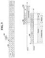
- FIG. 3shows an implementation of the transmit anticipation time and frequency-hop table, according to another example embodiment of the present invention.
- the figuredepicts frequency-hop table 304 , its pointer 302 and the receiver and transmitter timelines.
- Frequency-hop table 304represents an order of frequency channels used by both the receiver and the transmitter to communicate.
- the order of the channelsis typically pseudo-random. For instance, table 304 shows ranks 0-24 in the top row of the table. These ranks reflect the order of the channels used by the devices and correspond to the channel in the lower row of the table. The communicating devices would use the channels in the order provided.
- table 304may be used in applications using frequency-hopping spread spectrum or similar techniques.
- Pointer 302represents the current channel to be used by the transmitting device. More specifically, a transmitting device begins transmitting according to the channel indicated by the pointer. In one embodiment, this channel represents the last channel used by the transmitting device or the channel immediately following the last channel used. This use of the pointer by a transmitting device ensures that the channels are utilized equally because the transmitting devices transmit according to the frequency-hop table.
- the receiver and transmitter timelinesdepict the channels used by a receiver and transmitter as a function of time. In this example, time increases from left to right.
- the receiverbegins listening at the start of the Rx activation as shown by the arrow and block 306 . This represents the time at which the receiver is listening for a transmission from the transmitter. In this instance, the receiver is listening to channel 20 , which corresponds to rank 15 of table 304 .
- the transmitter timelinedepicts the transmitter beginning to transmit at the start of the Tx anticipation time as shown by the arrow at the start of the Tx anticipation time and block 308 .
- the transmitterbegins transmitting on the channel that corresponds to the pointer 302 .
- the pointerindicates rank 5 and channel 4 .
- the transmitterchanges frequency according to the wireless communications protocol being implemented and the table 304 as shown by block 308 .
- the Tx anticipation timeis the time the transmitter begins transmitting in relation to the Rx activation time.
- the Tx anticipation timeis selected so that, during the Rx activation time, the transmitter is transmitting on the same channel to which the receiver is listening.
- the Tx anticipation timeis a function of the current rank determined by pointer 302 and the Rx activation channel of the receiver. More specifically, the anticipation time is calculated using the number of the channels in table 304 between the current rank and the Rx activation channel. This number is multiplied by the time the transmitter is active on any one channel (dwell time) plus the time required to switch to a new channel (blank time).
- the transmittersends preamble frames as shown by the transmitter timeline from channel 4 to channel 9 . After the transmitter reaches the transmit anticipation time, it transmits a preamble frame using the listening channel followed by the remainder of the message.
- the receiving deviceacquires the transmitter using the preamble frame and tracks the transmitter according to the frequency hop table, as shown on the receiver timeline.
- the transmittertransmits one or more preamble frames after transmitting the preamble frame using the listening channel.
- FIG. 3depicts preamble frames transmitted on the listening channel ( 20 ) and a subsequent channel ( 24 ). Using this method, the number of preamble frames can be increased so as to improve quality of the acquisition phase between the transmitter and the receiver.
- the receivercontinues listening on the channel until the listening window is over as shown by block 310 .
- the listening windowmay only be long enough to receive a single message resulting in a short active time of the receiver and a reduction in power consumption.
- the listening shown by block 310is not implemented.
- the listening windowmay be longer to accommodate several messages, or devices which are not synchronized.
- the central deviceoften requires a longer listening window because devices such as keyfobs lose synchronization.
- the pointercan represent the last channel used by the receiving device or the channel immediately following the last channel used by the receiving device.
- the central devicecan implement a pointer for each monitoring device.
- the central devicebegins transmitting on the channel indicated by the pointer that corresponds to the receiving monitoring device.
- the central device and the monitoring deviceswill use the next channel in the frequency-hop table.
- This use of pointersalso ensures equal utilization of channels because the transmitter transmits according to the frequency-hop table for each monitoring device. This embodiment is particularly useful for situations where the transmitting device is the only device that transmits to the receiving device as can sometimes be the case in a system where a central device transmits to monitoring devices. Accordingly, an alternate scheme can be used for a monitoring device transmitting to a central device.
- the transmitting devicedoes not calculate a transmission anticipation time. Instead, the transmitting device begins transmitting on the channel indicated by the pointer at the Rx activation time because the first transmitting channel is the same as the receiving channel.
- Other methodscan be used to determine the starting transmission channel. For example, the receiving channel can be periodically changed for each receiving device and the pointers at the transmitting device are changed accordingly. In some instances, transmissions using channels that have not been used equally can be added to balance the use of the channels, or the central device can periodically send information to control the use of listening channels by the monitoring devices.
- FIG. 4depicts a flow chart for a method of transmitting data in accordance with another example embodiment of the present invention.
- the methodis particularly useful for controlling the transfer of data files large enough to require the use of many data packets.
- the methodcan be implemented to increase the throughput of the wireless communications link while allowing other communications during the transfer of a large data file. The increased throughput and other factors can also reduce the power consumption necessary for the transmission of the large data file.
- the monitoring devicehas one or more data files to transmit to the central device. This situation should not be considered exclusive, as for example, the central device or another monitoring device may have one or more data files to transmit to a monitoring device.
- the transmitting devicesends an indication that a large data file is ready to be sent to the receiving device as depicted in block 402 .
- the receiving devicesends a start message to the transmitting device as shown in block 404 .
- the transmitting devicesends consecutive packets (block 406 ) until one of two conditions (blocks 408 and 412 ) is met.
- the first conditionis met after the entire file has been transmitted, and the transmission has been completed as shown in block 410 .
- the second conditionis met when the current transmission period has ended.
- Several embodiments of the present inventionimplement variations of the transmission period. For instance, it may be advantageous to limit the transmission period of a monitoring device to the central device so that other monitoring devices may communicate to the central device. Alternatively, the transmission period may be limited to allow the transmitting or receiving device to perform processing of the data or other functions. In one such embodiment, the transmission period for large data transfers is limited to 812.5 ms out of 1 second intervals.
- the transmitting devicestops transmitting the file during the time reserved for other functions as depicted in block 414 .
- the receiving devicecan send a message to the transmitting device during this reserved period as shown in block 416 .
- the transmitting devicecan take appropriate action (block 418 ). For instance, the receiving block may alert the transmitting device of lost packets so that the transmitting device can send the lost packets a second time. If, however, the transmitting device does not receive a message from the receiving device, and the reserved time has passed, the transmitting device resumes sending packets as shown in block 406 .
- FIG. 5 and FIG. 6depict a transmission format for short and long messages, according to another example embodiment of the present invention.
- the systemimplements the long or short messages depending upon the characteristics of the data to be transferred. For instance, one embodiment uses short messages for all monitoring devices control and status data and long messages for longer data structures like large files.
- the short messagesare limited to a few bytes, while the long messages are used for data structures (or files) having many bytes. For instance, a long message might contain several hundred kilobytes (KB) of video, voice or other data.
- KBkilobytes
- a short messageis built with 2 types of frames: preamble frames and data frames.
- Preamble framesare used at the beginning of each message during the acquisition stage of the transmission.
- the preamble framesinclude a bit pattern for assisting the receiver in locking onto a transmission as depicted by the “Learn” block of the short message preamble frame.
- the Learn blockshows alternating bits 0 and 1 , a common example of such a learning pattern.
- a received signal strength index measurementcan also be achieved by the receiver to discriminate noise (when no transmission is present) from a real carrier.
- the preamble bitscan also be used to determine the bit rate used by the transmitter and to verify that the bit rate corresponds to the expected bit rate.
- the preamble framecan also contain other types of information.
- the preamblemay contain system identification bits that permit the receiver to verify that the current signal is originated from a known transmitter.
- the data framesfollow the preamble frames. Typically, much of a data frame is dedicated for data (the “Data 1 ”, “Data 2 ” and “Data 3 ” fields) and ends with an error detection field, such as a cyclical-redundancy-check (CRC).
- CRCcyclical-redundancy-check
- the message formatis changed to allow a better usage of the bandwidth of the radio channel.
- the long messagesare arranged in fixed length packets. In some instances, the file size can exceed 200 KB and can use a large part of the radio channel time.
- the long messagesare transmitted using packets containing a number of data frames in multiples of the number of channels used by the communications devices. For instance, the system of FIG. 4 uses either 5 or 25 channels for communications because the long packet format has 25 frames and 5 and 25 are the only integer divisors (other than 1) of 25.
- the long message formatwhen compared to the short message format, the long message format reduces the number of bytes used for communication overhead (e.g., preamble, sync pattern and CRC) in relation to the number of bytes used to transfer the file data. Additionally, the long messages can be implemented using longer frames to reduce the number of channels used to complete the file transfer. Since each change in channel includes a blank time, the total throughput of the transfer can be increased by reducing the number of changes in channels used throughout the file transfer. The advantages of the increased throughput must be balanced against the disadvantages of increasing the dwell time in order to increase the frame size. For example, increasing the dwell time can adversely affect the systems susceptibility to loss of data on a particular channel.
- the short and long message formatsare implemented using the method of transmitting data depicted in FIG. 4 and the “Large File Transfer” (LFT) timeline of FIG. 6 .
- the transmitting methodis initiated by short messages (e.g., from the source and one from the central device to start the transfer), as depicted by the ready and start blocks of the LFT timeline.
- the device receiving the large filehandles the arbitration for the transmitting method.
- the receiving devicedoes not send a short message every transfer period. Instead, the receiving device sends a short message periodically (e.g., every “n” seconds) or when a problem occurs with the transmission, such as when the amount of corrupted (lost) frames reaches a given level.
- the receiving devicecan request that the lost frames be resent.
- the transmitting devicelistens for a message from the receiving device. If a short message is not received, the packet transmission resumes after the reserved time is complete.
- error recovery methodscan be implemented depending upon the size of the data structure.
- a simple redundancy schemeis used.
- the transmitting deviceduplicates selected frames of the transmitted short message within the same packet.
- the duplicate framescan be such that they are transmitted on different channels to avoid interference on a particular channel. Should a frame and its duplicate be lost, the receiving device can use a negative acknowledge message to request the message or frame be resent.
- Each data framecontains a CRC field for error detection purposes.
- the receiving deviceuses the CRC field to detect lost frames and records the lost frames.
- the receiving devicesends a short message indicating the lost frames using frame and packet numbers.
- the frame and packet numbersare grouped in individual data frames (i.e., each data frame contains one frame and one packet number), permitting the error-free part of the short message to be used.
- the monitoring deviceshave their time period (Rx activation cycle) pre-programmed and stored in Flash memory.
- the monitoring devicetransmits this period value to the central device, and the central device stores the period in memory.
- the central deviceuses the stored period value to determine the time at which the monitoring device will be listening. This can facilitate communications by avoiding possible communication collisions between monitoring devices and by potentially utilizing more of the transmission period.
- the central devicetransmits the time period for each monitoring device during an initialization phase.
- the monitoring device and central deviceuse the transmitted time period for future communications.
- individual messagesare acknowledged by the recipient. If the sender does not receive a positive acknowledge message or a negative acknowledge message, the sender repeats the original message. To avoid collision between several senders trying to repeat a message, the devices delay their retransmissions.
- the delaysare implemented by each sender to prevent simultaneous retransmissions by several devices.
- the frequency-hopping table used for channel selectionis chosen from several tables stored in each device.
- the central devicewill select one of the several tables.
- the tablesmay be selected randomly, or alternatively, they may be selected using a pre-programmed system.
- One such pre-programmed selection methoduses a system identification number to select one of the tables.
- the monitoring devicesuse a default table (also known by the panel) until the system identification has been transmitted by the central device. This can be advantageous where several similar systems are used in close proximity with each other allowing for different channel sequences of the various systems.
- datacan be corrupted when several monitoring devices transmit at the same time.
- messagescan be delayed according to their importance or content for a fixed offset time.
- each monitoring devicemay be configured to transmit low priority messages during a specified time that is different from the other monitoring devices.
- one embodiment of the systemuses cryptographic techniques.
- the central deviceuses a master key (factory set) and a random value to generate a diversified key.
- the random valueis transmitted to the monitoring devices during an initialization phase, and the monitoring devices generate the same diversified key.
- the central device serial numberis used as site identification and is also transmitted to the monitoring devices.
- a Message Authentication Check (MAC)is calculated for each message.
- the diversified keyis again diversified using a time counter, so it will evolve every second.
- the critical data sent over the airis encrypted using a XOR operation with the result of the cryptographic operation.
- cryptographycan be used to generate a 128-bit encrypted string, used for either MAC field having 16 least-significant-bits or for XOR scrambling with all 128 bits.
- FIG. 7illustrates a process for detecting an intruder, according to an example embodiment of the present invention.
- the process shown in FIG. 7may be implemented, for example, using a monitoring system such as that shown in FIG. 1 or otherwise described herein.
- An intrusion sensorsuch as a window or door contact, located at a perimeter of a facility detects whether the contact subject, window or door, has been breached 710 . If, for example, a window has been opened, the window contact (intrusion sensor) sends a signal to a corresponding integrated motion sensor/camera located at the interior of the facility.
- the motion sensorUpon receipt of the intrusion signal, the motion sensor is activated 720 and the integrated camera is set to a “ready” mode without initiating recording 730 .
- the motion detectorremains activated 740 and when motion is detected, the integrated motion sensor/camera is again triggered 750 . Once motion is detected, the camera turns “on” and captures images of the source of the motion 760 .
- the video imagesare sent to a central device for further evaluation 770 . Further evaluation may include determining (manually or automatically using, e.g., machine visions) whether the source of the motion is human, an animal such as a pet, or another moving object. If the source is determined to be human, further evaluation may reveal whether any identifying images were captured, whether the human is an intruder or an inhabitant of the facility, and face recognition may be used to identify a previously unknown person intruding on the facility.
- FIG. 8illustrates an approach to processing recorded images in a monitoring system, according to another embodiment of the present invention.
- An intrusion sensoris activated at block 810 when an intruder breaches the perimeter of a facility. If a motion sensor/image-capture device detects motion at block 820 , an alarm condition is reported at block 830 and an image search is initiated at block 840 .
- the alarm conditionmay be transmitted to, for example, a central device, a law enforcement agency, a private security monitoring facility, a cell phone, or a personal computer.
- the motion sensor/image-capture deviceWith the image search at block 840 the motion sensor/image-capture device generates video data.
- the video datais processed at block 850 to evaluate whether the source of the motion is captured in the video data and whether the source of the motion can be identified. For example, if the source is a false trigger such as a pet or authorized employee/inhabitant that was locked out, the system can identify the false trigger and cease further monitoring or alarm activities.
- a status reportis transmitted to the appropriate authorities at block 860 . If the intruder is not detectable, the system determines whether a predetermined amount of time has been exceeded at block 870 . If the video data searching has not exceeded the predetermined time delay, the system continues searching the data for images of the intruder. However, if the predetermined time delay has been exceeded, a status report is transmitted and other means are optionally implemented to identify and apprehend the intruder, such as by sounding an alarm and/or alerting authorities or other security personnel.
- the motion detectorswhile always powered, are also always in a state of motion sensing.
- the central device and/or monitoring devicecan recognize the chain of events as an authorized person within the monitored zone merely opening a window or door.
- the systemis programmed to recognize alternate orders of signal transmission as corresponding to permitted behavior, thereby reducing the potential for the monitoring system creating, and responding to, a false alarm.
- the home entry intrusion sensorcorresponds to a delayed-response motion sensor such that the motion sensor waits to transmit a signal indicating that motion has been detected to accommodate a monitoring system control keypad located near the entrance.
- Another zone located nearbysuch as a kitchen, includes a standard motion sensor that transmits the signal when motion is detected.
- the systemrecognizes that motion sensed in the nearby room (e.g., person setting grocery bags down in the kitchen) following a delayed sensing of motion in the entry zone is likely an authorized user and an alarm will not sound for a predetermined length of time. If the system is not deactivated or reset before the predetermined length of time expires, the alarm will still sound.
- the number of nearby zones configured with such a relationship with the delayed motion sensor in the entry zoneshould be limited to ensure that an actual intruder is not provided enough time to traverse the premises without being detected.
Landscapes
- Engineering & Computer Science (AREA)
- Computer Networks & Wireless Communication (AREA)
- Signal Processing (AREA)
- Mobile Radio Communication Systems (AREA)
- Monitoring And Testing Of Transmission In General (AREA)
Abstract
Description
Claims (26)
Priority Applications (4)
| Application Number | Priority Date | Filing Date | Title |
|---|---|---|---|
| US11/389,674US8155105B2 (en) | 2005-09-22 | 2006-03-24 | Spread spectrum wireless communication and monitoring arrangement and method |
| AU2006294990AAU2006294990B2 (en) | 2005-09-22 | 2006-09-21 | Spread spectrum wireless communication and monitoring arrangement and method |
| PCT/US2006/036778WO2007038189A2 (en) | 2005-09-22 | 2006-09-21 | Spread spectrum wireless communication and monitoring arrangement and method |
| CA2623395ACA2623395C (en) | 2005-09-22 | 2006-09-21 | Spread spectrum wireless communication and monitoring arrangement and method |
Applications Claiming Priority (2)
| Application Number | Priority Date | Filing Date | Title |
|---|---|---|---|
| US71936905P | 2005-09-22 | 2005-09-22 | |
| US11/389,674US8155105B2 (en) | 2005-09-22 | 2006-03-24 | Spread spectrum wireless communication and monitoring arrangement and method |
Publications (2)
| Publication Number | Publication Date |
|---|---|
| US20070066311A1 US20070066311A1 (en) | 2007-03-22 |
| US8155105B2true US8155105B2 (en) | 2012-04-10 |
Family
ID=37884875
Family Applications (1)
| Application Number | Title | Priority Date | Filing Date |
|---|---|---|---|
| US11/389,674Active2029-12-17US8155105B2 (en) | 2005-09-22 | 2006-03-24 | Spread spectrum wireless communication and monitoring arrangement and method |
Country Status (4)
| Country | Link |
|---|---|
| US (1) | US8155105B2 (en) |
| AU (1) | AU2006294990B2 (en) |
| CA (1) | CA2623395C (en) |
| WO (1) | WO2007038189A2 (en) |
Cited By (8)
| Publication number | Priority date | Publication date | Assignee | Title |
|---|---|---|---|---|
| US20090167862A1 (en)* | 2005-09-22 | 2009-07-02 | Jentoft Keith A | Security monitoring with programmable mapping |
| US20100297943A1 (en)* | 2009-05-19 | 2010-11-25 | Jonathan Kaplan | Wireless video hub |
| US20110230182A1 (en)* | 2009-11-19 | 2011-09-22 | Benjamin Stump | Management system for monitoring and controlling remote sites and equipment |
| WO2014169070A1 (en) | 2013-04-09 | 2014-10-16 | Rsi Video Technologies, Inc. | Low-cost, compact security monitoring |
| US9237743B2 (en) | 2014-04-18 | 2016-01-19 | The Samuel Roberts Noble Foundation, Inc. | Systems and methods for trapping animals |
| US9472067B1 (en) | 2013-07-23 | 2016-10-18 | Rsi Video Technologies, Inc. | Security devices and related features |
| US9495845B1 (en) | 2012-10-02 | 2016-11-15 | Rsi Video Technologies, Inc. | Control panel for security monitoring system providing cell-system upgrades |
| US10076109B2 (en) | 2012-02-14 | 2018-09-18 | Noble Research Institute, Llc | Systems and methods for trapping animals |
Families Citing this family (25)
| Publication number | Priority date | Publication date | Assignee | Title |
|---|---|---|---|---|
| DE102005059800A1 (en)* | 2005-12-14 | 2007-06-21 | Siemens Ag | Method for operating a radio network and subscriber device for such a network |
| US8364968B2 (en)* | 2006-05-19 | 2013-01-29 | Symantec Corporation | Dynamic web services systems and method for use of personal trusted devices and identity tokens |
| US8149748B2 (en)* | 2006-11-14 | 2012-04-03 | Raytheon Company | Wireless data networking |
| US20080151050A1 (en) | 2006-12-20 | 2008-06-26 | Self Michael R | Enhanced Multimedia Intrusion Notification System and Method |
| US10331708B2 (en)* | 2007-06-29 | 2019-06-25 | Microsoft Technology Licensing, Llc | Dynamic awareness involving location |
| DE102007036751A1 (en)* | 2007-08-03 | 2009-02-05 | Ista International Gmbh | Method and system for bidirectional radio communication |
| US7856047B2 (en)* | 2007-09-21 | 2010-12-21 | Honeywell International Inc. | System and method for concurrent frequency hopping of radio communications |
| US8595748B1 (en)* | 2007-12-21 | 2013-11-26 | Ibiquity Digital Corporation | Systems and methods for transmitting and receiving large objects via digital radio broadcast |
| JP5024095B2 (en)* | 2008-02-08 | 2012-09-12 | 沖電気工業株式会社 | Wireless transmission apparatus, program, and method |
| WO2009112928A2 (en)* | 2008-03-10 | 2009-09-17 | Nortel Networks Limited | Methods for control signaling for wireless systems |
| US8170886B2 (en) | 2008-03-28 | 2012-05-01 | The Nielsen Company (U.S.), Llc | Systems, methods, and apparatus to generate an energy consumption index |
| US8032317B2 (en) | 2008-05-15 | 2011-10-04 | The Nielsen Company (Us), Llc | System and methods for metering and analyzing energy consumption of events within a portable device |
| KR101252090B1 (en)* | 2008-09-17 | 2013-04-12 | 엘지디스플레이 주식회사 | Liquid Crystal Display |
| US8823793B2 (en)* | 2008-11-10 | 2014-09-02 | At&T Intellectual Property I, L.P. | System and method for performing security tasks |
| JP5550261B2 (en)* | 2009-05-29 | 2014-07-16 | キヤノン株式会社 | Data processing apparatus, data processing method and program using ring bus |
| US8410973B2 (en)* | 2010-03-18 | 2013-04-02 | The Boeing Company | Activating motion detectors |
| GB2481579B (en)* | 2010-06-25 | 2014-11-26 | Enmodus Ltd | Monitoring of power-consumption |
| US10044402B2 (en) | 2010-06-25 | 2018-08-07 | Enmodus Limited | Timing synchronization for wired communications |
| CA3057093A1 (en) | 2012-05-18 | 2013-11-21 | Lojack Corporation | Low-power wireless vehicle locating unit |
| US9143741B1 (en)* | 2012-08-17 | 2015-09-22 | Kuna Systems Corporation | Internet protocol security camera connected light bulb/system |
| EP3955229B1 (en) | 2015-03-12 | 2024-05-01 | Alarm.com Incorporated | Providing internet access through a property monitoring system |
| US10164854B2 (en)* | 2015-11-20 | 2018-12-25 | International Business Machines Corporation | Providing dynamic latency in an integration flow |
| US11670969B2 (en)* | 2019-01-18 | 2023-06-06 | Ossia Inc. | Wireless power transmission system capable of changing power transmission frequency |
| US20210185265A1 (en)* | 2019-12-13 | 2021-06-17 | Sony Semiconductor Solutions Corporation | Methods of sensor mode switching in event based sensor and imaging camera for low power application |
| CN112037450A (en)* | 2020-08-16 | 2020-12-04 | 嘉兴新博信息科技有限公司 | High-safety security monitoring and anti-theft alarm system for intelligent building |
Citations (93)
| Publication number | Priority date | Publication date | Assignee | Title |
|---|---|---|---|---|
| WO1988007474A1 (en) | 1987-04-02 | 1988-10-06 | Manville Corporation | Carton with improved handle |
| US4821262A (en)* | 1986-09-18 | 1989-04-11 | Nissan Motor Company, Limited | System for transmitting and receiving data in a time-division multiplex mode applicable to a vehicle |
| US4857912A (en) | 1988-07-27 | 1989-08-15 | The United States Of America As Represented By The Secretary Of The Navy | Intelligent security assessment system |
| JPH01236397A (en) | 1988-03-17 | 1989-09-21 | Fujitsu General Ltd | automatic notification system |
| US5068850A (en)* | 1989-06-12 | 1991-11-26 | Moore Industries-International, Inc. | Parameter value communication system |
| US5436905A (en)* | 1994-05-16 | 1995-07-25 | Industrial Technology Research Institute | Group randomly addressed polling MAC protocol for wireless data |
| US5448290A (en) | 1991-08-23 | 1995-09-05 | Go-Video Inc. | Video security system with motion sensor override, wireless interconnection, and mobile cameras |
| EP0676733A1 (en) | 1994-04-09 | 1995-10-11 | Harrison Brothers (Steeplejacks) Ltd., | Detection system and method of operating same |
| US5473368A (en) | 1988-11-29 | 1995-12-05 | Hart; Frank J. | Interactive surveillance device |
| US5568482A (en)* | 1994-11-23 | 1996-10-22 | Yurie Systems, Inc. | Low speed radio link system and method designed for ATM transport |
| US5574979A (en)* | 1994-06-03 | 1996-11-12 | Norand Corporation | Periodic interference avoidance in a wireless radio frequency communication system |
| EP0811959A1 (en) | 1996-06-07 | 1997-12-10 | GRUNDIG Aktiengesellschaft | Radio controlled alarm system with substations and safe data transmission |
| US5703368A (en) | 1995-10-04 | 1997-12-30 | Optex Co., Ltd. | Passive-type infrared sensor system for detecting human body |
| EP0856826A2 (en) | 1997-02-04 | 1998-08-05 | Neil James Stevenson | A security system |
| US5819124A (en) | 1994-09-13 | 1998-10-06 | Timothy Laurie Somner | Security system |
| US5832384A (en)* | 1993-11-12 | 1998-11-03 | Balachandran; Kumar | Method and apparatus for frequency agility in a communication system |
| GB2325548A (en) | 1997-05-21 | 1998-11-25 | Richard Parviz Nabavi | Security alarm systems |
| JPH11154292A (en) | 1997-11-21 | 1999-06-08 | Kazuya Deguchi | Integrated warning system |
| WO2000003367A1 (en) | 1998-07-10 | 2000-01-20 | Loureiro Nunes Solposto Manuel | Televideo monitoring device |
| US6169732B1 (en)* | 1999-06-29 | 2001-01-02 | Motorola, Inc. | Method and apparatus in a wireless communication system |
| US6188715B1 (en)* | 1998-04-09 | 2001-02-13 | Andrzej Partyka | Frequency hopping system for intermittent transmission with receiver using individual tracking, FFT, and authentication |
| WO2001027763A1 (en) | 1999-10-08 | 2001-04-19 | Ivex Corporation | Networked digital security system and methods |
| US6223048B1 (en)* | 1997-12-16 | 2001-04-24 | Alcatel | Method of generating a frequency-hopping sequence for radio communication, as well as radio facility and radio communication system therefor |
| US20010004375A1 (en)* | 1998-04-09 | 2001-06-21 | Andrzej Partyka | Telemetry system with authenticaiton |
| EP1115264A2 (en) | 1999-12-30 | 2001-07-11 | AT&T Corp. | Remote monitoring through the BRG |
| GB2358504A (en) | 1997-10-11 | 2001-07-25 | Menvier | Alarm or detection system |
| US6271752B1 (en) | 1998-10-02 | 2001-08-07 | Lucent Technologies, Inc. | Intelligent multi-access system |
| US6323784B1 (en)* | 1997-03-11 | 2001-11-27 | Nec Corporation | Radio selective call receiver and channel selecting method thereof |
| US20020005781A1 (en)* | 2000-04-04 | 2002-01-17 | Britton Rick A. | Networks and circuits for alarm system operations |
| US20020055334A1 (en)* | 2000-11-07 | 2002-05-09 | Simmons Sean B. | Communication channel detector and channel detection method |
| WO2002046919A2 (en) | 2000-12-06 | 2002-06-13 | Koninklijke Philips Electronics N.V. | Method and apparatus to select the best video frame to transmit to a remote station for closed circuit television (cctv) based residential barea security monitoring |
| US20020075941A1 (en)* | 2000-12-14 | 2002-06-20 | Motorola, Inc. | Multiple access frequency hopping network with interference anticipation |
| US6414955B1 (en)* | 1999-03-23 | 2002-07-02 | Innovative Technology Licensing, Llc | Distributed topology learning method and apparatus for wireless networks |
| US20020159434A1 (en)* | 2001-02-12 | 2002-10-31 | Eleven Engineering Inc. | Multipoint short range radio frequency system |
| US6476858B1 (en) | 1999-08-12 | 2002-11-05 | Innovation Institute | Video monitoring and security system |
| US20020164990A1 (en)* | 2001-05-07 | 2002-11-07 | Krishna Balachandran | Enhanced frequency hopping in a wireless system |
| US20020171557A1 (en) | 2001-05-18 | 2002-11-21 | Wegener William E. | Security electronic system |
| US6504479B1 (en) | 2000-09-07 | 2003-01-07 | Comtrak Technologies Llc | Integrated security system |
| US20030031231A1 (en)* | 2001-07-04 | 2003-02-13 | Korea Electronics Technology Institute | Adaptive frequency hopping apparatus in wireless personal area network system |
| US20030065407A1 (en) | 2000-04-28 | 2003-04-03 | Echelon Corporation | Internet based home communications system |
| DE10150745A1 (en) | 2001-09-26 | 2003-04-10 | Ernst-Otto Hoffmann | Digital transmission system links security camera to mobile phone is motion sensor activated |
| US20030103475A1 (en)* | 2001-07-09 | 2003-06-05 | Heppe Stephen B. | Two-way timing and calibration methods for time division multiple access radio networks |
| US6603799B1 (en)* | 2000-01-03 | 2003-08-05 | Sharp Laboratories Of America, Inc. | Method for detecting the hopping sequence of an interfering wireless system |
| JP2003233889A (en) | 2002-02-07 | 2003-08-22 | Omron Corp | Personal security terminal in home security alarm system |
| US20030193563A1 (en) | 2002-04-12 | 2003-10-16 | Tsuyoshi Suzuki | Television door intercom apparatus |
| US20030202117A1 (en) | 2002-04-22 | 2003-10-30 | Garner Steven Alonzo | Security monitor screens & cameras |
| EP1363260A1 (en) | 2002-05-07 | 2003-11-19 | Radio Systèmes Ingenierie (Société Anonyme) | Method for radio frequency communication among multiple devices and monitoring system using the method |
| US6683919B1 (en)* | 1999-06-16 | 2004-01-27 | National Semiconductor Corporation | Method and apparatus for noise bandwidth reduction in wireless communication signal reception |
| US6690414B2 (en) | 2000-12-12 | 2004-02-10 | Koninklijke Philips Electronics N.V. | Method and apparatus to reduce false alarms in exit/entrance situations for residential security monitoring |
| US20040046661A1 (en) | 2002-09-11 | 2004-03-11 | Vaccaro Dennis David | Automatic detection and monitoring of perimeter physical movement |
| US20040109059A1 (en) | 2002-11-12 | 2004-06-10 | Kevin Kawakita | Hybrid joint photographer's experts group (JPEG) /moving picture experts group (MPEG) specialized security video camera |
| US20040128091A1 (en)* | 2002-10-09 | 2004-07-01 | Delin Kevin A. | Sensor web |
| US6759957B2 (en) | 2001-11-28 | 2004-07-06 | Matsushita Electric Industrial Co., Ltd. | Home security system |
| US20040131014A1 (en)* | 2003-01-03 | 2004-07-08 | Microsoft Corporation | Frame protocol and scheduling system |
| WO2004064355A2 (en) | 2003-01-03 | 2004-07-29 | Gloolabs, Inc. | Method and apparatus for device communications |
| US20040155781A1 (en) | 2003-01-22 | 2004-08-12 | Deome Dennis E. | Interactive personal security system |
| WO2004079684A1 (en) | 2003-03-05 | 2004-09-16 | Vish Eraman | A security system |
| US20040189244A1 (en)* | 2003-03-25 | 2004-09-30 | Armen Karapetyan | Apparatus for prolonging rechargeable battery life and power in a wireless communicating hand-held system |
| US6804542B1 (en)* | 2000-09-22 | 2004-10-12 | Telefonaktiebolaget Lm Ericsson (Publ) | Sleep modes in peer-to-peer communications |
| US20040205824A1 (en) | 2003-04-10 | 2004-10-14 | Chic Technology Corp. | Web home security system |
| US20040205823A1 (en) | 2003-04-10 | 2004-10-14 | Chic Technology Corp. | Residential security system |
| US20040203808A1 (en)* | 2002-08-29 | 2004-10-14 | Saurabh Mathur | Automatic channel selection in a radio access network |
| US20040239497A1 (en)* | 2001-06-04 | 2004-12-02 | Yaakov Schwartzman | Method and apparatus for two-way communications amongst a plurality of communications devices |
| WO2004114648A2 (en) | 2003-06-19 | 2004-12-29 | L-3 Communications Corporation | Method and apparatus for providing a scalable multi-camera distributed video processing and visualization surveillance system |
| US20040264397A1 (en)* | 2002-12-16 | 2004-12-30 | Mathilde Benveniste | Power-saving mechanism for periodic traffic streams in wireless local-area networks |
| US20050030927A1 (en)* | 2003-07-10 | 2005-02-10 | Staccato Communications Inc. | Data transmission in a communication system |
| US20050041613A1 (en)* | 2001-09-10 | 2005-02-24 | Carmen Kuhl | Method of transmitting time-critical scheduling information between single network devices in a wireless network using slotted point-to-point links |
| US20050043024A1 (en)* | 2003-07-31 | 2005-02-24 | Noritake Shiga | Mobile station, mobile communication system, and program |
| JP2005071064A (en) | 2003-08-25 | 2005-03-17 | Hitachi Hybrid Network Co Ltd | Home security system |
| US20050083902A1 (en)* | 2003-10-09 | 2005-04-21 | Oki Electric Industry Co., Ltd. | Wireless communication system and method of reducing power consumption thereof |
| US20050091051A1 (en)* | 2002-03-08 | 2005-04-28 | Nippon Telegraph And Telephone Corporation | Digital signal encoding method, decoding method, encoding device, decoding device, digital signal encoding program, and decoding program |
| US20050134450A1 (en) | 2003-12-23 | 2005-06-23 | Honeywell International, Inc. | Integrated alarm detection and verification device |
| US20050134454A1 (en) | 2003-12-23 | 2005-06-23 | Honeywell International, Inc. | Security system with wireless RF portable monitor |
| US20050136882A1 (en)* | 2003-12-18 | 2005-06-23 | Boulton Philip A. | Method and system for maintaining synchronization in low-power mode over a frequency hopping radio link |
| US6925105B1 (en)* | 2000-05-01 | 2005-08-02 | Andrzej Partyka | Overhead reduction in system for intermittent transmission |
| US20050198359A1 (en)* | 2000-04-07 | 2005-09-08 | Basani Vijay R. | Method and apparatus for election of group leaders in a distributed network |
| US20050249181A1 (en)* | 2004-05-04 | 2005-11-10 | Rajiv Vijayan | Staggered pilot transmission for channel estimation and time tracking |
| US20050254475A1 (en)* | 1995-10-05 | 2005-11-17 | Kubler Joseph J | Hierarchical data collection network supporting packetized voice communications among wireless terminals and telephones |
| US20050275530A1 (en)* | 2004-05-27 | 2005-12-15 | Lawrence Kates | Wireless sensor system |
| US6983243B1 (en)* | 2000-10-27 | 2006-01-03 | Lucent Technologies Inc. | Methods and apparatus for wireless transmission using multiple description coding |
| US20060013168A1 (en)* | 2004-06-04 | 2006-01-19 | Avneesh Agrawal | Coding and modulation for broadcast and multicast services in a wireless communication system |
| US6999773B2 (en)* | 2003-06-30 | 2006-02-14 | Motorola, Inc. | Method and apparatus for control channel scheduling in a packet data communication system |
| US20060045053A1 (en)* | 2003-09-11 | 2006-03-02 | Yossi Erlich | Method for data transmission within a wireless local area network |
| US20060198426A1 (en)* | 2000-05-01 | 2006-09-07 | Andrzej Partyka | Overhead reduction in frequency hopping system for intermittent transmission |
| US20060238413A1 (en)* | 2005-04-25 | 2006-10-26 | Elta Systems Ltd. | Method and system for calibration of a radio direction finder |
| US7180903B1 (en)* | 1999-05-10 | 2007-02-20 | Telefonaktiebolaget Lm Ericsson (Publ) | Resource management in uncoordinated frequency hopping system |
| US20070064669A1 (en)* | 2005-03-30 | 2007-03-22 | Motorola, Inc. | Method and apparatus for reducing round trip latency and overhead within a communication system |
| US7392053B1 (en)* | 2003-04-08 | 2008-06-24 | Intel Corporation | Method and apparatus for selective listening in a dynamically configured wireless network |
| US7420149B2 (en)* | 2005-08-24 | 2008-09-02 | Avaak, Inc. | Network sensor system and protocol |
| US7436789B2 (en)* | 2003-10-09 | 2008-10-14 | Sarnoff Corporation | Ad Hoc wireless node and network |
| US7496059B2 (en)* | 2004-12-09 | 2009-02-24 | Itt Manufacturing Enterprises, Inc. | Energy-efficient medium access control protocol and system for sensor networks |
| US7522688B2 (en)* | 2004-04-27 | 2009-04-21 | The Sapling Company, Inc. | Wireless clock system and method |
| US7664162B1 (en)* | 2002-02-20 | 2010-02-16 | Logitech Europe S.A. | High-frequency wireless peripheral device with auto-connection and auto-synchronization |
Family Cites Families (1)
| Publication number | Priority date | Publication date | Assignee | Title |
|---|---|---|---|---|
| US6353385B1 (en)* | 2000-08-25 | 2002-03-05 | Hyperon Incorporated | Method and system for interfacing an intrusion detection system to a central alarm system |
- 2006
- 2006-03-24USUS11/389,674patent/US8155105B2/enactiveActive
- 2006-09-21CACA2623395Apatent/CA2623395C/enactiveActive
- 2006-09-21WOPCT/US2006/036778patent/WO2007038189A2/enactiveApplication Filing
- 2006-09-21AUAU2006294990Apatent/AU2006294990B2/ennot_activeCeased
Patent Citations (99)
| Publication number | Priority date | Publication date | Assignee | Title |
|---|---|---|---|---|
| US4821262A (en)* | 1986-09-18 | 1989-04-11 | Nissan Motor Company, Limited | System for transmitting and receiving data in a time-division multiplex mode applicable to a vehicle |
| WO1988007474A1 (en) | 1987-04-02 | 1988-10-06 | Manville Corporation | Carton with improved handle |
| JPH01236397A (en) | 1988-03-17 | 1989-09-21 | Fujitsu General Ltd | automatic notification system |
| US4857912A (en) | 1988-07-27 | 1989-08-15 | The United States Of America As Represented By The Secretary Of The Navy | Intelligent security assessment system |
| US5473368A (en) | 1988-11-29 | 1995-12-05 | Hart; Frank J. | Interactive surveillance device |
| US5068850A (en)* | 1989-06-12 | 1991-11-26 | Moore Industries-International, Inc. | Parameter value communication system |
| US5448290A (en) | 1991-08-23 | 1995-09-05 | Go-Video Inc. | Video security system with motion sensor override, wireless interconnection, and mobile cameras |
| US5832384A (en)* | 1993-11-12 | 1998-11-03 | Balachandran; Kumar | Method and apparatus for frequency agility in a communication system |
| EP0676733A1 (en) | 1994-04-09 | 1995-10-11 | Harrison Brothers (Steeplejacks) Ltd., | Detection system and method of operating same |
| US5436905A (en)* | 1994-05-16 | 1995-07-25 | Industrial Technology Research Institute | Group randomly addressed polling MAC protocol for wireless data |
| US5574979A (en)* | 1994-06-03 | 1996-11-12 | Norand Corporation | Periodic interference avoidance in a wireless radio frequency communication system |
| US5819124A (en) | 1994-09-13 | 1998-10-06 | Timothy Laurie Somner | Security system |
| US5568482A (en)* | 1994-11-23 | 1996-10-22 | Yurie Systems, Inc. | Low speed radio link system and method designed for ATM transport |
| US5703368A (en) | 1995-10-04 | 1997-12-30 | Optex Co., Ltd. | Passive-type infrared sensor system for detecting human body |
| US20050254475A1 (en)* | 1995-10-05 | 2005-11-17 | Kubler Joseph J | Hierarchical data collection network supporting packetized voice communications among wireless terminals and telephones |
| EP0811959A1 (en) | 1996-06-07 | 1997-12-10 | GRUNDIG Aktiengesellschaft | Radio controlled alarm system with substations and safe data transmission |
| EP0856826A2 (en) | 1997-02-04 | 1998-08-05 | Neil James Stevenson | A security system |
| US6323784B1 (en)* | 1997-03-11 | 2001-11-27 | Nec Corporation | Radio selective call receiver and channel selecting method thereof |
| GB2325548A (en) | 1997-05-21 | 1998-11-25 | Richard Parviz Nabavi | Security alarm systems |
| GB2358504A (en) | 1997-10-11 | 2001-07-25 | Menvier | Alarm or detection system |
| JPH11154292A (en) | 1997-11-21 | 1999-06-08 | Kazuya Deguchi | Integrated warning system |
| US6223048B1 (en)* | 1997-12-16 | 2001-04-24 | Alcatel | Method of generating a frequency-hopping sequence for radio communication, as well as radio facility and radio communication system therefor |
| US20010004375A1 (en)* | 1998-04-09 | 2001-06-21 | Andrzej Partyka | Telemetry system with authenticaiton |
| US6188715B1 (en)* | 1998-04-09 | 2001-02-13 | Andrzej Partyka | Frequency hopping system for intermittent transmission with receiver using individual tracking, FFT, and authentication |
| WO2000003367A1 (en) | 1998-07-10 | 2000-01-20 | Loureiro Nunes Solposto Manuel | Televideo monitoring device |
| US6271752B1 (en) | 1998-10-02 | 2001-08-07 | Lucent Technologies, Inc. | Intelligent multi-access system |
| US6414955B1 (en)* | 1999-03-23 | 2002-07-02 | Innovative Technology Licensing, Llc | Distributed topology learning method and apparatus for wireless networks |
| US7180903B1 (en)* | 1999-05-10 | 2007-02-20 | Telefonaktiebolaget Lm Ericsson (Publ) | Resource management in uncoordinated frequency hopping system |
| US6683919B1 (en)* | 1999-06-16 | 2004-01-27 | National Semiconductor Corporation | Method and apparatus for noise bandwidth reduction in wireless communication signal reception |
| US6169732B1 (en)* | 1999-06-29 | 2001-01-02 | Motorola, Inc. | Method and apparatus in a wireless communication system |
| US6476858B1 (en) | 1999-08-12 | 2002-11-05 | Innovation Institute | Video monitoring and security system |
| WO2001027763A1 (en) | 1999-10-08 | 2001-04-19 | Ivex Corporation | Networked digital security system and methods |
| EP1115264A2 (en) | 1999-12-30 | 2001-07-11 | AT&T Corp. | Remote monitoring through the BRG |
| US6603799B1 (en)* | 2000-01-03 | 2003-08-05 | Sharp Laboratories Of America, Inc. | Method for detecting the hopping sequence of an interfering wireless system |
| US20020005781A1 (en)* | 2000-04-04 | 2002-01-17 | Britton Rick A. | Networks and circuits for alarm system operations |
| US20050198359A1 (en)* | 2000-04-07 | 2005-09-08 | Basani Vijay R. | Method and apparatus for election of group leaders in a distributed network |
| US20030065407A1 (en) | 2000-04-28 | 2003-04-03 | Echelon Corporation | Internet based home communications system |
| US20060198426A1 (en)* | 2000-05-01 | 2006-09-07 | Andrzej Partyka | Overhead reduction in frequency hopping system for intermittent transmission |
| US6925105B1 (en)* | 2000-05-01 | 2005-08-02 | Andrzej Partyka | Overhead reduction in system for intermittent transmission |
| US6504479B1 (en) | 2000-09-07 | 2003-01-07 | Comtrak Technologies Llc | Integrated security system |
| US6804542B1 (en)* | 2000-09-22 | 2004-10-12 | Telefonaktiebolaget Lm Ericsson (Publ) | Sleep modes in peer-to-peer communications |
| US6983243B1 (en)* | 2000-10-27 | 2006-01-03 | Lucent Technologies Inc. | Methods and apparatus for wireless transmission using multiple description coding |
| US20020055334A1 (en)* | 2000-11-07 | 2002-05-09 | Simmons Sean B. | Communication channel detector and channel detection method |
| US6411209B1 (en) | 2000-12-06 | 2002-06-25 | Koninklijke Philips Electronics N.V. | Method and apparatus to select the best video frame to transmit to a remote station for CCTV based residential security monitoring |
| WO2002046919A2 (en) | 2000-12-06 | 2002-06-13 | Koninklijke Philips Electronics N.V. | Method and apparatus to select the best video frame to transmit to a remote station for closed circuit television (cctv) based residential barea security monitoring |
| US6700487B2 (en) | 2000-12-06 | 2004-03-02 | Koninklijke Philips Electronics N.V. | Method and apparatus to select the best video frame to transmit to a remote station for CCTV based residential security monitoring |
| US6690414B2 (en) | 2000-12-12 | 2004-02-10 | Koninklijke Philips Electronics N.V. | Method and apparatus to reduce false alarms in exit/entrance situations for residential security monitoring |
| US20020075941A1 (en)* | 2000-12-14 | 2002-06-20 | Motorola, Inc. | Multiple access frequency hopping network with interference anticipation |
| US20020159434A1 (en)* | 2001-02-12 | 2002-10-31 | Eleven Engineering Inc. | Multipoint short range radio frequency system |
| US20020164990A1 (en)* | 2001-05-07 | 2002-11-07 | Krishna Balachandran | Enhanced frequency hopping in a wireless system |
| US20020171557A1 (en) | 2001-05-18 | 2002-11-21 | Wegener William E. | Security electronic system |
| US20040239497A1 (en)* | 2001-06-04 | 2004-12-02 | Yaakov Schwartzman | Method and apparatus for two-way communications amongst a plurality of communications devices |
| US20030031231A1 (en)* | 2001-07-04 | 2003-02-13 | Korea Electronics Technology Institute | Adaptive frequency hopping apparatus in wireless personal area network system |
| US20030103475A1 (en)* | 2001-07-09 | 2003-06-05 | Heppe Stephen B. | Two-way timing and calibration methods for time division multiple access radio networks |
| US20050041613A1 (en)* | 2001-09-10 | 2005-02-24 | Carmen Kuhl | Method of transmitting time-critical scheduling information between single network devices in a wireless network using slotted point-to-point links |
| DE10150745A1 (en) | 2001-09-26 | 2003-04-10 | Ernst-Otto Hoffmann | Digital transmission system links security camera to mobile phone is motion sensor activated |
| US6759957B2 (en) | 2001-11-28 | 2004-07-06 | Matsushita Electric Industrial Co., Ltd. | Home security system |
| EP1316933B1 (en) | 2001-11-28 | 2006-08-09 | Matsushita Electric Industrial Co., Ltd. | Home security system |
| JP2003233889A (en) | 2002-02-07 | 2003-08-22 | Omron Corp | Personal security terminal in home security alarm system |
| US7664162B1 (en)* | 2002-02-20 | 2010-02-16 | Logitech Europe S.A. | High-frequency wireless peripheral device with auto-connection and auto-synchronization |
| US20050091051A1 (en)* | 2002-03-08 | 2005-04-28 | Nippon Telegraph And Telephone Corporation | Digital signal encoding method, decoding method, encoding device, decoding device, digital signal encoding program, and decoding program |
| US20030193563A1 (en) | 2002-04-12 | 2003-10-16 | Tsuyoshi Suzuki | Television door intercom apparatus |
| EP1499098A1 (en) | 2002-04-12 | 2005-01-19 | Aiphone Co., Ltd. | Video doorphone |
| US20030202117A1 (en) | 2002-04-22 | 2003-10-30 | Garner Steven Alonzo | Security monitor screens & cameras |
| EP1363260A1 (en) | 2002-05-07 | 2003-11-19 | Radio Systèmes Ingenierie (Société Anonyme) | Method for radio frequency communication among multiple devices and monitoring system using the method |
| US20040203808A1 (en)* | 2002-08-29 | 2004-10-14 | Saurabh Mathur | Automatic channel selection in a radio access network |
| US20040046661A1 (en) | 2002-09-11 | 2004-03-11 | Vaccaro Dennis David | Automatic detection and monitoring of perimeter physical movement |
| US20040128091A1 (en)* | 2002-10-09 | 2004-07-01 | Delin Kevin A. | Sensor web |
| US20040109059A1 (en) | 2002-11-12 | 2004-06-10 | Kevin Kawakita | Hybrid joint photographer's experts group (JPEG) /moving picture experts group (MPEG) specialized security video camera |
| US20040264397A1 (en)* | 2002-12-16 | 2004-12-30 | Mathilde Benveniste | Power-saving mechanism for periodic traffic streams in wireless local-area networks |
| WO2004064355A2 (en) | 2003-01-03 | 2004-07-29 | Gloolabs, Inc. | Method and apparatus for device communications |
| US20040131014A1 (en)* | 2003-01-03 | 2004-07-08 | Microsoft Corporation | Frame protocol and scheduling system |
| US20040155781A1 (en) | 2003-01-22 | 2004-08-12 | Deome Dennis E. | Interactive personal security system |
| WO2004079684A1 (en) | 2003-03-05 | 2004-09-16 | Vish Eraman | A security system |
| US20040189244A1 (en)* | 2003-03-25 | 2004-09-30 | Armen Karapetyan | Apparatus for prolonging rechargeable battery life and power in a wireless communicating hand-held system |
| US7392053B1 (en)* | 2003-04-08 | 2008-06-24 | Intel Corporation | Method and apparatus for selective listening in a dynamically configured wireless network |
| US20040205823A1 (en) | 2003-04-10 | 2004-10-14 | Chic Technology Corp. | Residential security system |
| US20040205824A1 (en) | 2003-04-10 | 2004-10-14 | Chic Technology Corp. | Web home security system |
| US20050024206A1 (en) | 2003-06-19 | 2005-02-03 | Supun Samarasekera | Method and apparatus for providing a scalable multi-camera distributed video processing and visualization surveillance system |
| WO2004114648A2 (en) | 2003-06-19 | 2004-12-29 | L-3 Communications Corporation | Method and apparatus for providing a scalable multi-camera distributed video processing and visualization surveillance system |
| US6999773B2 (en)* | 2003-06-30 | 2006-02-14 | Motorola, Inc. | Method and apparatus for control channel scheduling in a packet data communication system |
| US20050030927A1 (en)* | 2003-07-10 | 2005-02-10 | Staccato Communications Inc. | Data transmission in a communication system |
| US20050043024A1 (en)* | 2003-07-31 | 2005-02-24 | Noritake Shiga | Mobile station, mobile communication system, and program |
| JP2005071064A (en) | 2003-08-25 | 2005-03-17 | Hitachi Hybrid Network Co Ltd | Home security system |
| US20060045053A1 (en)* | 2003-09-11 | 2006-03-02 | Yossi Erlich | Method for data transmission within a wireless local area network |
| US20050083902A1 (en)* | 2003-10-09 | 2005-04-21 | Oki Electric Industry Co., Ltd. | Wireless communication system and method of reducing power consumption thereof |
| US7436789B2 (en)* | 2003-10-09 | 2008-10-14 | Sarnoff Corporation | Ad Hoc wireless node and network |
| US20050136882A1 (en)* | 2003-12-18 | 2005-06-23 | Boulton Philip A. | Method and system for maintaining synchronization in low-power mode over a frequency hopping radio link |
| US20050134450A1 (en) | 2003-12-23 | 2005-06-23 | Honeywell International, Inc. | Integrated alarm detection and verification device |
| WO2005065196A2 (en) | 2003-12-23 | 2005-07-21 | Honeywell International, Inc. | Security system with wireless rf portable monitor |
| US20050134454A1 (en) | 2003-12-23 | 2005-06-23 | Honeywell International, Inc. | Security system with wireless RF portable monitor |
| US7522688B2 (en)* | 2004-04-27 | 2009-04-21 | The Sapling Company, Inc. | Wireless clock system and method |
| US20050249181A1 (en)* | 2004-05-04 | 2005-11-10 | Rajiv Vijayan | Staggered pilot transmission for channel estimation and time tracking |
| US20050275530A1 (en)* | 2004-05-27 | 2005-12-15 | Lawrence Kates | Wireless sensor system |
| US20060013168A1 (en)* | 2004-06-04 | 2006-01-19 | Avneesh Agrawal | Coding and modulation for broadcast and multicast services in a wireless communication system |
| US7496059B2 (en)* | 2004-12-09 | 2009-02-24 | Itt Manufacturing Enterprises, Inc. | Energy-efficient medium access control protocol and system for sensor networks |
| US20070064669A1 (en)* | 2005-03-30 | 2007-03-22 | Motorola, Inc. | Method and apparatus for reducing round trip latency and overhead within a communication system |
| US20060238413A1 (en)* | 2005-04-25 | 2006-10-26 | Elta Systems Ltd. | Method and system for calibration of a radio direction finder |
| US7420149B2 (en)* | 2005-08-24 | 2008-09-02 | Avaak, Inc. | Network sensor system and protocol |
Non-Patent Citations (2)
| Title |
|---|
| Shrenharsha Rao, SWRA041: Implementing a Bidirectional Frequency Hopping Application With TRF6903 and MSP430, Sep. 2004, Texas Instruments.* |
| Shrenharsha Rao, SWRA041: Implementing a Bidirectional Wireless UART Application With TRF6903 and MSP430, Sep. 2004, Texas Instruments.* |
Cited By (13)
| Publication number | Priority date | Publication date | Assignee | Title |
|---|---|---|---|---|
| US9189934B2 (en) | 2005-09-22 | 2015-11-17 | Rsi Video Technologies, Inc. | Security monitoring with programmable mapping |
| US20090167862A1 (en)* | 2005-09-22 | 2009-07-02 | Jentoft Keith A | Security monitoring with programmable mapping |
| US9679455B2 (en) | 2005-09-22 | 2017-06-13 | Rsi Video Technologies, Inc. | Security monitoring with programmable mapping |
| US20100297943A1 (en)* | 2009-05-19 | 2010-11-25 | Jonathan Kaplan | Wireless video hub |
| US20110230182A1 (en)* | 2009-11-19 | 2011-09-22 | Benjamin Stump | Management system for monitoring and controlling remote sites and equipment |
| US8442515B2 (en)* | 2009-11-19 | 2013-05-14 | Kentrox, Inc. | Management system for monitoring and controlling remote sites and equipment |
| US10076109B2 (en) | 2012-02-14 | 2018-09-18 | Noble Research Institute, Llc | Systems and methods for trapping animals |
| US10470454B2 (en) | 2012-02-14 | 2019-11-12 | Noble Research Institute, Llc | Systems and methods for trapping animals |
| US9495845B1 (en) | 2012-10-02 | 2016-11-15 | Rsi Video Technologies, Inc. | Control panel for security monitoring system providing cell-system upgrades |
| WO2014169070A1 (en) | 2013-04-09 | 2014-10-16 | Rsi Video Technologies, Inc. | Low-cost, compact security monitoring |
| US9472067B1 (en) | 2013-07-23 | 2016-10-18 | Rsi Video Technologies, Inc. | Security devices and related features |
| US9237743B2 (en) | 2014-04-18 | 2016-01-19 | The Samuel Roberts Noble Foundation, Inc. | Systems and methods for trapping animals |
| US9668467B2 (en) | 2014-04-18 | 2017-06-06 | The Samuel Roberts Noble Foundation, Inc. | Systems and methods for trapping animals |
Also Published As
| Publication number | Publication date |
|---|---|
| AU2006294990A1 (en) | 2007-04-05 |
| US20070066311A1 (en) | 2007-03-22 |
| CA2623395A1 (en) | 2007-04-05 |
| WO2007038189A2 (en) | 2007-04-05 |
| WO2007038189A8 (en) | 2007-06-07 |
| CA2623395C (en) | 2015-10-27 |
| WO2007038189A3 (en) | 2008-11-13 |
| AU2006294990B2 (en) | 2010-09-02 |
Similar Documents
| Publication | Publication Date | Title |
|---|---|---|
| US8155105B2 (en) | Spread spectrum wireless communication and monitoring arrangement and method | |
| US7835343B1 (en) | Calculating transmission anticipation time using dwell and blank time in spread spectrum communications for security systems | |
| US9679455B2 (en) | Security monitoring with programmable mapping | |
| EP2011093B1 (en) | Security monitoring with programmable mapping | |
| US8714449B2 (en) | Method and device for arming and disarming status in a facility monitoring system | |
| EP3608887B1 (en) | Iot enabled wireless one-go-all-go platform sensor network solution for connected home security systems | |
| US9282520B2 (en) | System and method for adaptive network technique using isochronous transmission | |
| US9743402B2 (en) | Polymorphism and priority inversion to handle different types of life style and life safety traffic in wireless sensor network for a connected home | |
| US20180247508A1 (en) | Detecting an intruder's wireless device during a break in to a premises | |
| EP2826279A1 (en) | A method for synchronizing state information of a home wireless system | |
| US10218943B2 (en) | Method and apparatus for triggering multiple data recording devices | |
| US20190073895A1 (en) | Alarm system | |
| JP3908043B2 (en) | Wireless transmitter | |
| JP4067812B2 (en) | Small power security system | |
| JP3748666B2 (en) | Transmitter used for security system | |
| KR100383664B1 (en) | Security System by Using Low Power Simple Wireless Network and Mobile Phone Network | |
| US20190116335A1 (en) | Method and apparatus for signaling multiple data recording devices | |
| WO2014188282A2 (en) | Low power protocols and processes for an alarm monitoring system | |
| JPH05143883A (en) | Wireless security system | |
| KR20060029899A (en) | Item loss prevention system using mobile communication terminal | |
| JPH05143882A (en) | Wireless security system |
Legal Events
| Date | Code | Title | Description |
|---|---|---|---|
| AS | Assignment | Owner name:RSIALARM, MINNESOTA Free format text:ASSIGNMENT OF ASSIGNORS INTEREST;ASSIGNORS:REIBEL, JEAN-MICHEL;JENTOFT, KEITH;SIGNING DATES FROM 20060503 TO 20060516;REEL/FRAME:017743/0600 Owner name:RSIALARM, MINNESOTA Free format text:ASSIGNMENT OF ASSIGNORS INTEREST;ASSIGNORS:REIBEL, JEAN-MICHEL;JENTOFT, KEITH;REEL/FRAME:017743/0600;SIGNING DATES FROM 20060503 TO 20060516 | |
| STCF | Information on status: patent grant | Free format text:PATENTED CASE | |
| CC | Certificate of correction | ||
| AS | Assignment | Owner name:RSI VIDEO TECHNOLOGIES, INC., MINNESOTA Free format text:CHANGE OF NAME;ASSIGNOR:RSIALARM;REEL/FRAME:032547/0728 Effective date:20050519 | |
| FPAY | Fee payment | Year of fee payment:4 | |
| AS | Assignment | Owner name:JPMORGAN CHASE BANK, N.A., AS ADMINISTRATIVE AGENT Free format text:SECURITY INTEREST;ASSIGNOR:RSI VIDEO TECHNOLOGIES, INC.;REEL/FRAME:047326/0752 Effective date:20181025 | |
| FEPP | Fee payment procedure | Free format text:ENTITY STATUS SET TO UNDISCOUNTED (ORIGINAL EVENT CODE: BIG.); ENTITY STATUS OF PATENT OWNER: LARGE ENTITY | |
| MAFP | Maintenance fee payment | Free format text:PAYMENT OF MAINTENANCE FEE, 8TH YEAR, LARGE ENTITY (ORIGINAL EVENT CODE: M1552); ENTITY STATUS OF PATENT OWNER: LARGE ENTITY Year of fee payment:8 | |
| MAFP | Maintenance fee payment | Free format text:PAYMENT OF MAINTENANCE FEE, 12TH YEAR, LARGE ENTITY (ORIGINAL EVENT CODE: M1553); ENTITY STATUS OF PATENT OWNER: LARGE ENTITY Year of fee payment:12 |