US8154601B2 - Television receiving system - Google Patents
Television receiving systemDownload PDFInfo
- Publication number
- US8154601B2 US8154601B2US11/817,906US81790606AUS8154601B2US 8154601 B2US8154601 B2US 8154601B2US 81790606 AUS81790606 AUS 81790606AUS 8154601 B2US8154601 B2US 8154601B2
- Authority
- US
- United States
- Prior art keywords
- data
- setup
- display
- wireless
- wireless communicator
- Prior art date
- Legal status (The legal status is an assumption and is not a legal conclusion. Google has not performed a legal analysis and makes no representation as to the accuracy of the status listed.)
- Expired - Fee Related, expires
Links
Images


Classifications
- H—ELECTRICITY
- H04—ELECTRIC COMMUNICATION TECHNIQUE
- H04N—PICTORIAL COMMUNICATION, e.g. TELEVISION
- H04N5/00—Details of television systems
- H04N5/38—Transmitter circuitry for the transmission of television signals according to analogue transmission standards
- H—ELECTRICITY
- H04—ELECTRIC COMMUNICATION TECHNIQUE
- H04N—PICTORIAL COMMUNICATION, e.g. TELEVISION
- H04N21/00—Selective content distribution, e.g. interactive television or video on demand [VOD]
- H04N21/40—Client devices specifically adapted for the reception of or interaction with content, e.g. set-top-box [STB]; Operations thereof
- H04N21/41—Structure of client; Structure of client peripherals
- H04N21/4104—Peripherals receiving signals from specially adapted client devices
- H04N21/4122—Peripherals receiving signals from specially adapted client devices additional display device, e.g. video projector
- H—ELECTRICITY
- H04—ELECTRIC COMMUNICATION TECHNIQUE
- H04N—PICTORIAL COMMUNICATION, e.g. TELEVISION
- H04N21/00—Selective content distribution, e.g. interactive television or video on demand [VOD]
- H04N21/40—Client devices specifically adapted for the reception of or interaction with content, e.g. set-top-box [STB]; Operations thereof
- H04N21/43—Processing of content or additional data, e.g. demultiplexing additional data from a digital video stream; Elementary client operations, e.g. monitoring of home network or synchronising decoder's clock; Client middleware
- H04N21/436—Interfacing a local distribution network, e.g. communicating with another STB or one or more peripheral devices inside the home
- H04N21/43615—Interfacing a Home Network, e.g. for connecting the client to a plurality of peripherals
- H—ELECTRICITY
- H04—ELECTRIC COMMUNICATION TECHNIQUE
- H04N—PICTORIAL COMMUNICATION, e.g. TELEVISION
- H04N21/00—Selective content distribution, e.g. interactive television or video on demand [VOD]
- H04N21/40—Client devices specifically adapted for the reception of or interaction with content, e.g. set-top-box [STB]; Operations thereof
- H04N21/43—Processing of content or additional data, e.g. demultiplexing additional data from a digital video stream; Elementary client operations, e.g. monitoring of home network or synchronising decoder's clock; Client middleware
- H04N21/436—Interfacing a local distribution network, e.g. communicating with another STB or one or more peripheral devices inside the home
- H04N21/4363—Adapting the video stream to a specific local network, e.g. a Bluetooth® network
- H04N21/43637—Adapting the video stream to a specific local network, e.g. a Bluetooth® network involving a wireless protocol, e.g. Bluetooth, RF or wireless LAN [IEEE 802.11]
- H—ELECTRICITY
- H04—ELECTRIC COMMUNICATION TECHNIQUE
- H04N—PICTORIAL COMMUNICATION, e.g. TELEVISION
- H04N21/00—Selective content distribution, e.g. interactive television or video on demand [VOD]
- H04N21/40—Client devices specifically adapted for the reception of or interaction with content, e.g. set-top-box [STB]; Operations thereof
- H04N21/47—End-user applications
- H04N21/485—End-user interface for client configuration
- H—ELECTRICITY
- H04—ELECTRIC COMMUNICATION TECHNIQUE
- H04N—PICTORIAL COMMUNICATION, e.g. TELEVISION
- H04N5/00—Details of television systems
- H04N5/44—Receiver circuitry for the reception of television signals according to analogue transmission standards
- H—ELECTRICITY
- H04—ELECTRIC COMMUNICATION TECHNIQUE
- H04N—PICTORIAL COMMUNICATION, e.g. TELEVISION
- H04N5/00—Details of television systems
- H04N5/44—Receiver circuitry for the reception of television signals according to analogue transmission standards
- H04N5/50—Tuning indicators; Automatic tuning control
- H—ELECTRICITY
- H04—ELECTRIC COMMUNICATION TECHNIQUE
- H04N—PICTORIAL COMMUNICATION, e.g. TELEVISION
- H04N21/00—Selective content distribution, e.g. interactive television or video on demand [VOD]
- H04N21/40—Client devices specifically adapted for the reception of or interaction with content, e.g. set-top-box [STB]; Operations thereof
- H04N21/43—Processing of content or additional data, e.g. demultiplexing additional data from a digital video stream; Elementary client operations, e.g. monitoring of home network or synchronising decoder's clock; Client middleware
- H04N21/442—Monitoring of processes or resources, e.g. detecting the failure of a recording device, monitoring the downstream bandwidth, the number of times a movie has been viewed, the storage space available from the internal hard disk
- H04N21/44227—Monitoring of local network, e.g. connection or bandwidth variations; Detecting new devices in the local network
Definitions
- the present inventionrelates to a television receiving system that can receive and utilize broadcast signals such as television broadcasting via wireless transmission.
- Japanese Patent Unexamined Publication No. 2001-358966discloses a conventional system that has a tuner and a display disposed separately in which broadcast signals received in the tuner are sent to the display via wireless transmission to show the broadcast signals on the display.
- the conventional television receiving systemhas sent the broadcast signals received by a single tuner to a single or a plurality of displays via wireless transmission. Only a single set of configuration parameters has been installed for the wireless transmission, it cannot be said, therefore, that the wireless transmission has always performed in an optimum condition for all displays disposed in different locations. For instance a display located near the tuner can receive broadcast signals correctly, on the other hand the receiving condition in a display located far away from the tuner may be unstable, causing difficulties often in receiving the broadcast signals due to worsened wave conditions or the like.
- the television receiving system of the present inventionincludes:
- a tunerincluding;
- a tuning deviceto tune the broadcast signals received by the antenna, an encoder to encode the broadcast signals received by the antenna, a first wireless communicator to transmit the broadcast signals encoded by the encoder as wireless signals, and a first controller to control tuning conditions of the tuning device,
- a displayincluding;
- a second wireless communicatorto receive the broadcast signals from the first wireless communicator, a decoder to decode the wireless signals received by the second wireless communicator as the broadcast signals, an image display to display the broadcast signals decoded by the decoder as images, an input device to input a user's commands, a setup-data creator to create setup-data of the tuner according to the input commands, a second storage to store the setup-data created, and a second controller to retrieve the setup-data from the second storage and send it to the first controller via the second wireless communicator and first wireless communicator,
- the first controllercontrols tuning condition of the tuning device according to the setup-data sent from the second controller.
- the displayis provided with a plurality of setup-data including configuration parameters for wireless transmission, so that a user can select a setup-data capable of providing an optimum receiving condition according to the location of the display to send the setup-data to the tuner. This can result in a stable receiving environment no matter where the display is located.
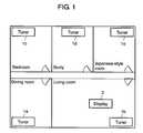
- FIG. 1shows an example of disposition of the tuners and display, when introduced in a home, of the television receiving system used in preferred embodiment 1 of the present invention.
- FIG. 2shows a block diagram of the television receiving system used in preferred embodiment 1 of the present invention.
- FIG. 3shows an example of configuration parameters of the setup-data in tuner 1 included in the television receiving system used in preferred embodiment 1 of the present invention.
- FIG. 4shows an example of control-panel provided in the display of the television receiving system used in preferred embodiment 1 of the present invention.
- FIG. 5shows an example of LED indicator provided in the tuner of the television receiving system used in preferred embodiment 1 of the present invention.
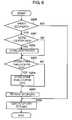
- FIG. 6shows a flowchart on setup-data executed in the display of the television receiving system used in preferred embodiment 1 of the present invention.
- FIG. 7shows a flowchart on setup-data executed in the tuner of the television receiving system used in preferred embodiment 1 of the present invention.
- FIG. 8shows a block diagram of the television receiving system used in preferred embodiment 2 of the present invention.
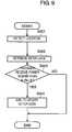
- FIG. 9shows a flowchart on location detection executed in the display of the television receiving system used in preferred embodiment 2 of the present invention.
- FIG. 10shows a block diagram of the television receiving system used in preferred embodiment 3 of the present invention.
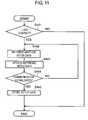
- FIG. 11shows a flowchart on restoration of wireless communication executed in the display and tuner of the television receiving system used in preferred embodiment 3 of the present invention.
- FIG. 1shows an example of disposition of the tuners and display, introduced in a home, of the television receiving system used in preferred embodiment 1 of the present invention.
- tuners 1 a , 1 b , 1 c , 1 d and 1 eare disposed respective rooms, totaled five.
- One display 2is disposed in the living room. In this case, display 2 communicates by wireless with tuner 1 b , located nearest to it, in the living room. A plurality of displays 2 can be available.
- FIG. 2shows a block diagram of the television receiving system used in preferred embodiment 1 of the present invention.
- the television receiving systemcomprises tuner 1 and display 2 both connected by wireless.
- Tuner 1 in FIG. 2corresponds to tuner 1 b in FIG. 1 .
- Tuner 1comprises: first wireless communicator 101 , tuning device 102 , encoder 103 , LED indicator 104 , first controller 105 and antenna 109 .
- Antenna 109receives broadcast signals propagated from outside.
- Tuning device 102tunes the broadcast signals received by antenna 109 .
- Encoder 103encodes the broadcast signals tuned by tuning device 102 .
- First wireless communicator 101transmits the broadcast signals encoded by encoder 103 as wireless signals.
- first controller 105controls tuning conditions of tuning device 102 .
- the tuning conditionsdiffer in the location of tuners 1 .
- First controller 105controls communication conditions of first wireless communicator 101 .
- the communication conditionsare controlled according to setup-data stored in display 1 described later.
- LED indicator 104shows a location data stored in the setup-data of tuner 1 by lighting LEDs.
- Display 2comprises: second wireless communicator 201 , decoder 202 , input device 203 , setup-data creator 204 , second storage 205 , second controller 206 and image display 209 .
- Second wireless communicator 201receives wireless signals from first wireless communicator 101 of tuner 1 .
- Decoder 202decodes the wireless signals received by second wireless communicator 201 as broadcast signals.
- Image display 209shows the broadcast signals decoded by decoder 202 as images.
- Input device 203accepts commands input by a user of display 2 .
- Setup-data creator 204creates setup-data according to commands input from input device 203 .
- Second storage 205stores the setup-data created by setup-data creator 204 .
- Second controller 206retrieves setup-data from second storage 205 to send the setup-data to first controller 105 of tuner 1 via second wireless communicator 201 and first wireless communicator 101 of tuner 1 .
- the setup-datarefers to configuration parameters that enable the system to send/receive wireless signals in an optimum condition between tuner 1 and display 2 .
- FIG. 3shows an example of configuration parameters of the setup-data to form the television receiving system used in preferred embodiment 1 of the present invention.
- the configuration parameters of setup-data 3include: location data 301 , active wireless channel data 302 , active bandwidth data 303 and transmit/receive power data 304 .
- Location data 301shows the position where display 2 is located, for instance dining room, living room, bedroom, study, Japanese-stile room or the like apply.
- Active wireless channel data 302shows the wireless channel used for communication between first wireless communicator 101 of tuner 1 and second wireless communicator 201 of display 2 . For instance if there are four wireless channels, channels 1 , 2 , 3 and 4 apply.
- Active bandwidth data 303shows the bandwidth actually used in the wireless channel, for instance a case of channel 1 using a wide bandwidth (“WIDE”) and using a narrow bandwidth (STANDARD or hereafter referred to as “STD”) apply.
- Transmit/receive power data 304shows the power consumed to transmit/receive signals in the wireless channel. For instance, the transmit/receive powers are thought to be lowered in case of good wireless communication condition (indicated as “LOW”) and to be raised in case of worsened wireless communication condition (shown as “HIGH”).
- FIG. 4shows an example of input device 203 provided in display 2 of the television receiving system used in preferred embodiment 1 of the present invention.
- a control-panel screenwhich is input device 203 , shows configuration parameters as shown in FIG. 3 .
- a touch paneloverlies the display screen, so that a user can input setup-data directly on the screen by a fingertip.
- the locationis installed as the living room, the active wireless channel as channel 1 , the active bandwidth as “WIDE” and the transmit/receive power as “LOW” respectively.
- the bandwidthaffects greatly on image quality, therefore the configuration parameter is titled as “image quality”.
- the locationcan be selected by touching the triangle marks on both sides.
- FIG. 5shows an example of LED indicator 104 provided on tuner 1 of the television receiving system used in preferred embodiment 1 of the present invention.
- Location data 301one of setup-data 3 , is indicated.
- LED 2is lit showing that display 2 is located in the living room.
- a usercan install the optimum setup-data 3 personally.
- the optimum setup-data installedis sent from display 2 to tuner 1 by wireless.
- FIG. 6shows the flowchart on setup-data executed in the display of the television receiving system used in preferred embodiment 1 of the present invention.
- new setup-data 3should be installed according to the following procedures:
- setup-data 3If setup-data 3 is to be updated, check whether location data 301 commanded by a user from the control-panel of display 2 should be installed newly or not (S 201 ). If location data 301 of display 2 is not to be installed newly, go to step S 203 .
- the usershould store active wireless channel data 302 , active bandwidth data 303 and transmit/receive power data 304 in second storage 205 (S 204 ).
- the setup-data sent to tuner 1 through a series of above processingwill be installed in relevant sections by first control 105 of tuner 1 .
- FIG. 7shows a flowchart on the setup-data executed in the tuner of the television receiving system used in preferred embodiment 1 of the present invention.
- step 104If the setup-data is to be updated, check whether location data 301 sent from display 2 has been installed newly or not (S 102 ). If location data 301 has not been newly installed, go to step 104 .
- location data 301 sent from display 2has been installed newly, location data 301 is reflected on LED indicator 104 . For instance, an LED turns on indicating a new location (S 103 ).
- first controller 105will install active wireless channel data 302 , active bandwidth data 303 and transmit/receive power data 304 in relevant sections (S 105 ).
- the television receiving system capable of installing an optimum setting for wireless transmissioncan be provided using a plurality of setup-data 3 which can be selected to install by a user personally.
- FIG. 8shows a block diagram of the television receiving system used in preferred embodiment 2 of the present invention.
- display 22is provided with location detector 207 to detect the location of display 22 .
- location detector 207monitors changes in configuration parameters installed previously as a current data. For instance, power consumption for transmit/receive in second wireless communicator 201 , which is one of the current data, is detected to have become higher than the parameter installed previously. If the detected value is over a predetermined value, location detector 207 sends the result to second controller 206 . In response to this, second controller 206 selects an optimum value for setup-data 3 .
- FIG. 9shows the process flowchart on location detection executed in the display of the television receiving system used in preferred embodiment 2 of the present invention.
- a detection programis always executed in location detector 207 to detect the location of display 22 (S 301 ). Specifically, an amount of power actually consumed to transmit/receive signals, which is one of current data, is calculated.
- FIG. 10shows a block diagram of the television receiving system used in preferred embodiment 3 of the present invention.
- the point different from exemplary embodiment 1 shown in FIG. 2is that tuner 13 is provided with first storage 106 .
- First storage 106stores setup-data 3 sent from display 2 . Even after setup-data 3 is updated, previous setup-data 3 remains being not deleted, so that a plurality of setup-data 3 installed in the past can be used also afterward.
- FIG. 11shows a program flowchart executed to restore wireless communication in the display and tuner of the television receiving system used in preferred embodiment 3 of the present invention.
- the program processing shown in FIG. 11is executed at the same time in a different cycle in both display 2 and tuner 13 .
- display 2retrieves another setup-data 3 from second storage 205 . Additionally, tuner 13 retrieves another setup-data 3 from first storage 106 (S 402 ).
- display 2updates setup-data 3 retrieved from second storage 205 to change settings of relevant sections of display 2 .
- tuner 13updates setup-data 3 retrieved from first storage 106 to change settings of relevant sections of tuner 13 (S 403 ).
- Display 2 and tuner 13respectively check whether the lost communication has been restored or not (S 404 ). If the communication has not restored, return to step S 402 to retrieve still another setup-data 3 (S 405 ).
- setup-data 3 used at the timeis installed permanently.
- the television receiving systemis realized that can restore a lost communication automatically even if display 2 loses wireless contact with tuner 13 .
- the television receiving system of the present inventioncan avoid interference on wireless communication caused by harmonic wave possible to occur in BS/CS channel tuning under different conditions within an area capable of communicating by wireless with tuner located in a house, garden or the like. Therefore, the system is useful as the television receiving technology to receive and utilize broadcast signals such as television broadcasting via wireless transmission.
Landscapes
- Engineering & Computer Science (AREA)
- Multimedia (AREA)
- Signal Processing (AREA)
- Computer Networks & Wireless Communication (AREA)
- Human Computer Interaction (AREA)
- Circuits Of Receivers In General (AREA)
- Two-Way Televisions, Distribution Of Moving Picture Or The Like (AREA)
- Details Of Television Systems (AREA)
- Radio Relay Systems (AREA)
Abstract
Description
THIS APPLICATION IS A U.S. NATIONAL PHASE APPLICATION OF PCT INTERNATIONAL APPLICATION PCT/JP2006/304337.
The present invention relates to a television receiving system that can receive and utilize broadcast signals such as television broadcasting via wireless transmission.
Japanese Patent Unexamined Publication No. 2001-358966 discloses a conventional system that has a tuner and a display disposed separately in which broadcast signals received in the tuner are sent to the display via wireless transmission to show the broadcast signals on the display.
The conventional television receiving system has sent the broadcast signals received by a single tuner to a single or a plurality of displays via wireless transmission. Only a single set of configuration parameters has been installed for the wireless transmission, it cannot be said, therefore, that the wireless transmission has always performed in an optimum condition for all displays disposed in different locations. For instance a display located near the tuner can receive broadcast signals correctly, on the other hand the receiving condition in a display located far away from the tuner may be unstable, causing difficulties often in receiving the broadcast signals due to worsened wave conditions or the like.
The television receiving system of the present invention includes:
an antenna to receive broadcast signals,
a tuner including;
a tuning device to tune the broadcast signals received by the antenna, an encoder to encode the broadcast signals received by the antenna, a first wireless communicator to transmit the broadcast signals encoded by the encoder as wireless signals, and a first controller to control tuning conditions of the tuning device,
and
a display including;
a second wireless communicator to receive the broadcast signals from the first wireless communicator, a decoder to decode the wireless signals received by the second wireless communicator as the broadcast signals, an image display to display the broadcast signals decoded by the decoder as images, an input device to input a user's commands, a setup-data creator to create setup-data of the tuner according to the input commands, a second storage to store the setup-data created, and a second controller to retrieve the setup-data from the second storage and send it to the first controller via the second wireless communicator and first wireless communicator,
wherein the first controller controls tuning condition of the tuning device according to the setup-data sent from the second controller.
In the television receiving system of the present invention, the display is provided with a plurality of setup-data including configuration parameters for wireless transmission, so that a user can select a setup-data capable of providing an optimum receiving condition according to the location of the display to send the setup-data to the tuner. This can result in a stable receiving environment no matter where the display is located.
- 1,13 tuner
- 2,22 display
- 3 setup-data
- 101 first wireless communicator
- 102 tuning device
- 103 encoder
- 104 LED indicator
- 105 first controller
- 106 first storage
- 109 antenna
- 201 second wireless communicator
- 202 decoder
- 203 input device
- 204 setup-data creator
- 205 second storage
- 206 second controller
- 207 location detector
- 209 image display
As mentioned above, the broadcast signals are sent to display2 as coded wireless signals. Other than controlling the series of processing,first controller 105 controls tuning conditions of tuningdevice 102. The tuning conditions differ in the location oftuners 1.First controller 105 controls communication conditions offirst wireless communicator 101. The communication conditions are controlled according to setup-data stored indisplay 1 described later.LED indicator 104 shows a location data stored in the setup-data oftuner 1 by lighting LEDs.
The setup-data is described next.
The setup-data refers to configuration parameters that enable the system to send/receive wireless signals in an optimum condition betweentuner 1 anddisplay 2.
As described above, to show crisp images indisplay 2 by receiving wireless signals fromtuner 1 in an optimum condition, a user can install the optimum setup-data 3 personally. The optimum setup-data installed is sent fromdisplay 2 totuner 1 by wireless.
The operation is described next with reference to the flowchart.FIG. 6 shows the flowchart on setup-data executed in the display of the television receiving system used inpreferred embodiment 1 of the present invention. Whendisplay 2 cannot adapt to the setup-data that has been stored previously (for instance whendisplay 2 has moved to a new location or the like), new setup-data 3 should be installed according to the following procedures:
[1] Check whether setup-data 3 ofdisplay 2 should be updated or not (S200). If not, exit from the loop and go to step S206.
[2] If setup-data 3 is to be updated, check whetherlocation data 301 commanded by a user from the control-panel ofdisplay 2 should be installed newly or not (S201). Iflocation data 301 ofdisplay 2 is not to be installed newly, go to step S203.
[3] Whenlocation data 301 ofdisplay 2 is to be installed newly, the user should store thenew location data 301 in second storage205 (S202).
[4] Additionally, check whether the configuration parameters on wireless signal control in setup-data 3 should be updated or not (S203). If the configuration parameters on wireless signal control are not updated, go to step S205.
[5] When the configuration parameters on wireless signal control are updated, the user should store activewireless channel data 302,active bandwidth data 303 and transmit/receivepower data 304 in second storage205 (S204).
[6] Retrieve from second storage205:location data 301 stored instep 202; and activewireless channel data 302,active bandwidth data 303, and transmit/receivepower data 304 stored respectively in step204 (S205).
[7] Send all the setup-data retrieved instep 205 to tuner1 (S206).
The setup-data sent totuner 1 through a series of above processing will be installed in relevant sections byfirst control 105 oftuner 1.
The operation is described next with reference to the flowchart.
[1] Check whether setup-data 3 intuner 1 should be updated or not (S101). If not, exit from the loop.
[2] If the setup-data is to be updated, check whetherlocation data 301 sent fromdisplay 2 has been installed newly or not (S102). Iflocation data 301 has not been newly installed, go to step104.
[3] Iflocation data 301 sent fromdisplay 2 has been installed newly,location data 301 is reflected onLED indicator 104. For instance, an LED turns on indicating a new location (S103).
[4] Additionally, check whether the configuration parameters on wireless signal control in setup-data 3 should be updated or not (S104). If the configuration parameters on wireless signal control are not to be updated, exit from the loop.
[5] When the configuration parameters on wireless signal control are updated,first controller 105 will install activewireless channel data 302,active bandwidth data 303 and transmit/receivepower data 304 in relevant sections (S105).
By executing the above processing, the television receiving system capable of installing an optimum setting for wireless transmission can be provided using a plurality of setup-data 3 which can be selected to install by a user personally.
The operation is described next with reference to the flowchart.
[1] A detection program is always executed inlocation detector 207 to detect the location of display22 (S301). Specifically, an amount of power actually consumed to transmit/receive signals, which is one of current data, is calculated.
[2] Retrieve transmit/receivepower data 304 installed currently, which is one of setup-data3 (S302).
[3] Compare the amount of retrieved transmit/receivepower data 304 with the amount of actual transmit/receive power (S303). If the difference is lower than a predetermined value, exit from the loop.
[4] If the difference is higher than the predetermined value, ask the user to update the setup-data installed currently (S304). Specifically, inform the user of the request by changing the indication of control-panel of display22 (for instance, by flashing the entire indications inFIG. 4 ).
As described above, by providingdisplay 22 withlocation detector 207 and executing the above processing, users can be informed of the wireless communication condition to reinstall an optimum setup-data immediately.
Specifically, whendisplay 2 loses wireless contact withtuner 13,display 2 andtuner 13 change setup-data 3, that have already been stored, each in a different cycle respectively and install just the setup-data 3 permanently at the time when the lost contact is restored and established again. This operation can restore the lost wireless contact automatically.
The operation is described next with reference to the flowchart.
[1] Check whetherdisplay 2 has lost wireless contact withtuner 13 or not (S401). If the wireless contact has not been lost, exit from the loop.
[2] If the wireless contact has been lost,display 2 retrieves another setup-data 3 fromsecond storage 205. Additionally,tuner 13 retrieves another setup-data 3 from first storage106 (S402).
[3] Next,display 2 updates setup-data 3 retrieved fromsecond storage 205 to change settings of relevant sections ofdisplay 2. Similarly,tuner 13 updates setup-data 3 retrieved fromfirst storage 106 to change settings of relevant sections of tuner13 (S403).
[4]Display 2 andtuner 13 respectively check whether the lost communication has been restored or not (S404). If the communication has not restored, return to step S402 to retrieve still another setup-data3 (S405).
[5] When the communication is established, setup-data 3 used at the time is installed permanently.
By allowingdisplay 2 andtuner 13 to perform the above described processing in a different cycle, all combinations for setup-data 3 ofdisplay 2 and setup-data 3 oftuner 13 can be checked. If the communication is not established in a given amount of time, processing may be forced to exit from the loop. In this occasion, a message should be shown saying that communication could not be established indisplay 2.
By executing the above processing, the television receiving system is realized that can restore a lost communication automatically even ifdisplay 2 loses wireless contact withtuner 13.
The television receiving system of the present invention can avoid interference on wireless communication caused by harmonic wave possible to occur in BS/CS channel tuning under different conditions within an area capable of communicating by wireless with tuner located in a house, garden or the like. Therefore, the system is useful as the television receiving technology to receive and utilize broadcast signals such as television broadcasting via wireless transmission.
Claims (7)
1. A television receiving system comprising:
an antenna to receive a broadcast signal;
a tuner including:
a tuning device to tune the broadcast signal received by the antenna,
an encoder to encode the broadcast signal tuned by the tuning device,
a first wireless communicator to transmit the broadcast signal encoded by the encoder as a wireless signal based on setup-data, and
a first controller to configure the first wireless communicator with the setup-data; and
a display including:
a second wireless communicator to receive the broadcast signal from the first wireless communicator,
a decoder to decode broadcast signal received by the second wireless communicator,
an image display device to display the broadcast signal decoded by the decoder as an image,
an input device to input a user's command,
a setup-data creator to create the setup-data which includes desired transmission parameters of the first wireless communicator according to the user's input command, the desired transmission parameters including transmit/receive power data indicating a transmit/receive power consumed in the wireless channel,
a second storage to store the setup-data created; and
a second controller to retrieve the setup-data from the second storage and send it to the first controller via the second wireless communicator and the first wireless communicator,
wherein the first controller configures the first wireless communicator with the setup-data sent from the second controller, and
wherein the display further comprises a location detector operable to detect the transmit/receive power data consumed in the second wireless communicator, and to obtain a difference between the detected transmit/receive power data and the transmit/receive power data included in the desired transmission parameters, and if the difference is higher than a predetermined value, the display requests the user to update the desired transmission parameters.
2. The television receiving system ofclaim 1 , wherein the tuner further comprises an LED indicator and the first controller controls the LED indicator according to the setup-data.
3. The television receiving system ofclaim 2 , wherein the setup-data further includes:
location data showing a position where the display is located;
active wireless channel data for use between the first wireless communicator and the second wireless communicator; and
active bandwidth data showing a bandwidth actually used in the wireless channel.
4. The television receiving system ofclaim 3 , wherein
the location detector detects a current data of the display,
the second controller compares a setup-data stored in the second storage with the current data to update the setup-data with the current data.
5. The television receiving system ofclaim 4 , wherein the current data is a transmit/receive power data to show a transmit/receive power consumed in the wireless channel.
6. The television receiving system ofclaim 2 ;
wherein the tuner further comprises a first storage for storing a plurality of setup-data previously installed; and
when the first wireless communicator loses contact with the second wireless communicator, the first controller retrieves a plurality of setup-data stored in the first storage in due order, and the second controller retrieves a plurality of setup-data stored in the second storage in due order to set an optimum setup-data to restore the communication.
7. The television receiving system ofclaim 6 , wherein
a time cycle when the first controller retrieves a plurality of setup-data stored in the first storage in due order differs from a time cycle when the second controller retrieves a plurality of setup-data stored in the second storage in due order, thus creating a good timing to set an optimum setup-data on the tuner and the display to restore the communication.
Applications Claiming Priority (4)
| Application Number | Priority Date | Filing Date | Title |
|---|---|---|---|
| JP2005066954 | 2005-03-10 | ||
| JP2005-066954 | 2005-03-10 | ||
| JPJP2005-066954 | 2005-03-10 | ||
| PCT/JP2006/304337WO2006095717A1 (en) | 2005-03-10 | 2006-03-07 | Television receiving system |
Publications (2)
| Publication Number | Publication Date |
|---|---|
| US20090049499A1 US20090049499A1 (en) | 2009-02-19 |
| US8154601B2true US8154601B2 (en) | 2012-04-10 |
Family
ID=36953311
Family Applications (1)
| Application Number | Title | Priority Date | Filing Date |
|---|---|---|---|
| US11/817,906Expired - Fee RelatedUS8154601B2 (en) | 2005-03-10 | 2006-03-07 | Television receiving system |
Country Status (5)
| Country | Link |
|---|---|
| US (1) | US8154601B2 (en) |
| EP (1) | EP1845708A4 (en) |
| JP (1) | JPWO2006095717A1 (en) |
| CN (1) | CN101138232A (en) |
| WO (1) | WO2006095717A1 (en) |
Families Citing this family (1)
| Publication number | Priority date | Publication date | Assignee | Title |
|---|---|---|---|---|
| JP5281853B2 (en)* | 2008-09-05 | 2013-09-04 | 株式会社日立製作所 | Television receiver |
Citations (14)
| Publication number | Priority date | Publication date | Assignee | Title |
|---|---|---|---|---|
| JP2001358966A (en) | 2000-06-14 | 2001-12-26 | Sony Corp | Television reception system, channel selection device and display device |
| WO2003007594A1 (en) | 2001-07-10 | 2003-01-23 | Sharp Kabushiki Kaisha | Av data transmitter, av data receiver, and av data displaying/reproducing apparatus |
| US20030072257A1 (en) | 2001-09-26 | 2003-04-17 | Hiroyasu Ikedo | Digital broadcast channel reception system and method and portable terminal for use in such system |
| US20040003051A1 (en) | 2002-06-27 | 2004-01-01 | Openpeak Inc. | Method, system, and computer program product for managing controlled residential or non-residential environments |
| JP2004336722A (en) | 2003-04-17 | 2004-11-25 | Sharp Corp | Wireless terminal, base device, wireless system, control program for wireless terminal, control program for base device, and computer-readable recording medium |
| JP2004336724A (en) | 2003-04-17 | 2004-11-25 | Sharp Corp | Display device, wireless communication system, display device control method, wireless communication system control method, display device control program, wireless communication system control program, and recording medium storing the program |
| JP2004343725A (en) | 2003-04-16 | 2004-12-02 | Sharp Corp | Wireless communication device, wireless AV system, operation control program, and recording medium recording the program |
| EP1489788A2 (en) | 2003-06-19 | 2004-12-22 | Microsoft Corporation | Wireless transmission interference avoidance on a device capable of carrying out wireless network communications |
| US20050028208A1 (en)* | 1998-07-17 | 2005-02-03 | United Video Properties, Inc. | Interactive television program guide with remote access |
| US20050097618A1 (en)* | 2003-11-04 | 2005-05-05 | Universal Electronics Inc. | System and method for saving and recalling state data for media and home appliances |
| US20050210515A1 (en)* | 2004-03-22 | 2005-09-22 | Lg Electronics Inc. | Server system for performing communication over wireless network and operating method thereof |
| EP1617648A1 (en) | 2003-04-16 | 2006-01-18 | Sharp Kabushiki Kaisha | Radio terminal, base device, wireless system, radio terminal control method, radio terminal control program, and computer-readable recording medium in which that program has been recorded |
| US20060258291A1 (en)* | 2003-05-21 | 2006-11-16 | Masashi Nakata | Radio communication device, radio communication system, wireless av system, radio transmission method, operation control program, and recording medium containing the program |
| US20070032198A1 (en)* | 2003-04-17 | 2007-02-08 | Sharp Kabushiki Kaisha | Transmitter, receiver, wireless system, control method, control program, and computer-readable recording medium containing the program |
- 2006
- 2006-03-07JPJP2007507118Apatent/JPWO2006095717A1/enactivePending
- 2006-03-07USUS11/817,906patent/US8154601B2/ennot_activeExpired - Fee Related
- 2006-03-07EPEP06728706Apatent/EP1845708A4/ennot_activeWithdrawn
- 2006-03-07CNCN200680007524.7Apatent/CN101138232A/enactivePending
- 2006-03-07WOPCT/JP2006/304337patent/WO2006095717A1/ennot_activeCeased
Patent Citations (21)
| Publication number | Priority date | Publication date | Assignee | Title |
|---|---|---|---|---|
| US20050028208A1 (en)* | 1998-07-17 | 2005-02-03 | United Video Properties, Inc. | Interactive television program guide with remote access |
| JP2001358966A (en) | 2000-06-14 | 2001-12-26 | Sony Corp | Television reception system, channel selection device and display device |
| WO2003007594A1 (en) | 2001-07-10 | 2003-01-23 | Sharp Kabushiki Kaisha | Av data transmitter, av data receiver, and av data displaying/reproducing apparatus |
| US20040193647A1 (en) | 2001-07-10 | 2004-09-30 | Toru Ueda | Av data transmitter, av data receiver, and av data displaying/reproducing apparatus |
| US20030072257A1 (en) | 2001-09-26 | 2003-04-17 | Hiroyasu Ikedo | Digital broadcast channel reception system and method and portable terminal for use in such system |
| US20040003051A1 (en) | 2002-06-27 | 2004-01-01 | Openpeak Inc. | Method, system, and computer program product for managing controlled residential or non-residential environments |
| EP1617648A1 (en) | 2003-04-16 | 2006-01-18 | Sharp Kabushiki Kaisha | Radio terminal, base device, wireless system, radio terminal control method, radio terminal control program, and computer-readable recording medium in which that program has been recorded |
| JP2004343725A (en) | 2003-04-16 | 2004-12-02 | Sharp Corp | Wireless communication device, wireless AV system, operation control program, and recording medium recording the program |
| US20070060152A1 (en) | 2003-04-16 | 2007-03-15 | Sharp Kabushiki Kaisha | Wireless terminal, base device, wireless system, wireless terminal control method, wireless terminal control program, and computer-readable storage medium storing same program |
| US7853977B2 (en) | 2003-04-17 | 2010-12-14 | Sharp Kabushiki Kaisha | Device and method for displaying images according to wireless reception degree |
| US7636132B2 (en)* | 2003-04-17 | 2009-12-22 | Sharp Kabushiki Kaisha | Transmitter, receiver, wireless system, control method, control program, and computer-readable recording medium containing the program |
| US20070044025A1 (en)* | 2003-04-17 | 2007-02-22 | Kenji Sakamoto | Display device, wireless communication system, method of controlling display device, method of controlling wireless communication system, display device control program, wireless communication system control program and storage media for storing the programs |
| EP1617596A1 (en) | 2003-04-17 | 2006-01-18 | Sharp Kabushiki Kaisha | Radio terminal, base device, wireless system, radio terminal control program, base device control program, and computer-readable recording medium |
| JP2004336724A (en) | 2003-04-17 | 2004-11-25 | Sharp Corp | Display device, wireless communication system, display device control method, wireless communication system control method, display device control program, wireless communication system control program, and recording medium storing the program |
| EP1622360A1 (en) | 2003-04-17 | 2006-02-01 | Sharp Kabushiki Kaisha | Display device, radio communication system, display device control method, radio communication system control method, display device control program, radio communication system control program, and recording media in which those programs have been recorded |
| JP2004336722A (en) | 2003-04-17 | 2004-11-25 | Sharp Corp | Wireless terminal, base device, wireless system, control program for wireless terminal, control program for base device, and computer-readable recording medium |
| US20070032198A1 (en)* | 2003-04-17 | 2007-02-08 | Sharp Kabushiki Kaisha | Transmitter, receiver, wireless system, control method, control program, and computer-readable recording medium containing the program |
| US20060258291A1 (en)* | 2003-05-21 | 2006-11-16 | Masashi Nakata | Radio communication device, radio communication system, wireless av system, radio transmission method, operation control program, and recording medium containing the program |
| EP1489788A2 (en) | 2003-06-19 | 2004-12-22 | Microsoft Corporation | Wireless transmission interference avoidance on a device capable of carrying out wireless network communications |
| US20050097618A1 (en)* | 2003-11-04 | 2005-05-05 | Universal Electronics Inc. | System and method for saving and recalling state data for media and home appliances |
| US20050210515A1 (en)* | 2004-03-22 | 2005-09-22 | Lg Electronics Inc. | Server system for performing communication over wireless network and operating method thereof |
Non-Patent Citations (4)
| Title |
|---|
| EP Office Action for 06-728706.0-2202, Mar. 30, 2011. |
| International Search Report for application No. PCT/JP2006/304337 dated Jun. 6, 2006. |
| Supplementary European Search Report for Application No. EP 06 72 8706, Feb. 2, 2010, Panasonic Corporation. |
| Supplementary European Search Report for EP 06 72 8706 dated Jan. 26, 2010. |
Also Published As
| Publication number | Publication date |
|---|---|
| JPWO2006095717A1 (en) | 2008-08-14 |
| WO2006095717A1 (en) | 2006-09-14 |
| EP1845708A4 (en) | 2010-03-03 |
| CN101138232A (en) | 2008-03-05 |
| US20090049499A1 (en) | 2009-02-19 |
| EP1845708A1 (en) | 2007-10-17 |
Similar Documents
| Publication | Publication Date | Title |
|---|---|---|
| JP5145352B2 (en) | Method and system for selecting each device of a wireless network, in particular a network of wireless lighting devices | |
| US5500691A (en) | Remote control identifier setup in a video system having both IR and RF transmitters | |
| JP2006109094A (en) | Remote controller, remote control system, and remote control method | |
| US9942603B2 (en) | Electronic system informing a first electronic device of user remote control activity involving a second electronic device | |
| US6795130B2 (en) | Signal receiving apparatus, remote controller, signal receiving system, and apparatus to be controlled | |
| US6759967B1 (en) | Remote control for activating household video products and services | |
| US20010005197A1 (en) | Remotely controlling electronic devices | |
| US10749704B2 (en) | Intelligent terminal remote controller-based internet-of-things control system and control method | |
| EP1633134B1 (en) | Wireless display system and method for a system | |
| US20080068247A1 (en) | State-Based Remote Control System | |
| US20050172228A1 (en) | Control device and method, information processing device and method, recording medium, and program | |
| US10439894B2 (en) | Communication apparatus, display apparatus and method of controlling the same | |
| JP6508597B2 (en) | Lighting controller and control method of lighting device | |
| JP2008263309A (en) | Electronic apparatus, remote controller, and remote control system | |
| US8154601B2 (en) | Television receiving system | |
| JP4927591B2 (en) | Electronic device startup mode setting method and electronic device | |
| KR20210033749A (en) | Appliance, appliance network system and connection method thereof | |
| US8120711B2 (en) | Display system and method of controlling a display system | |
| JP2000115649A (en) | Television receiver | |
| GB2256515A (en) | Interactive remote control | |
| KR20050068297A (en) | Remote control system and method for controlling of the same | |
| CN113391264A (en) | Control method, storage medium, controlled device, terminal device, positioning device | |
| JP2007221466A (en) | Reservation system, method and program, and portable terminal device | |
| KR200246377Y1 (en) | Street Light and Security Light Controlling Receiver Using FM DARC Signal | |
| KR20250105959A (en) | Setting up a remote control using Matter communication and setting up a scene function using it |
Legal Events
| Date | Code | Title | Description |
|---|---|---|---|
| AS | Assignment | Owner name:MATSUSHITA ELECTRIC INDUSTRIAL CO., LTD., JAPAN Free format text:ASSIGNMENT OF ASSIGNORS INTEREST;ASSIGNORS:SASAI, AKIRA;HATTORI, YOSHIKATSU;REEL/FRAME:020268/0789 Effective date:20070613 | |
| AS | Assignment | Owner name:PANASONIC CORPORATION, JAPAN Free format text:CHANGE OF NAME;ASSIGNOR:MATSUSHITA ELECTRIC INDUSTRIAL CO., LTD.;REEL/FRAME:021818/0725 Effective date:20081001 Owner name:PANASONIC CORPORATION,JAPAN Free format text:CHANGE OF NAME;ASSIGNOR:MATSUSHITA ELECTRIC INDUSTRIAL CO., LTD.;REEL/FRAME:021818/0725 Effective date:20081001 | |
| REMI | Maintenance fee reminder mailed | ||
| LAPS | Lapse for failure to pay maintenance fees | ||
| STCH | Information on status: patent discontinuation | Free format text:PATENT EXPIRED DUE TO NONPAYMENT OF MAINTENANCE FEES UNDER 37 CFR 1.362 | |
| FP | Lapsed due to failure to pay maintenance fee | Effective date:20160410 |