US8153290B2 - Heat dissipation for large battery packs - Google Patents
Heat dissipation for large battery packsDownload PDFInfo
- Publication number
- US8153290B2 US8153290B2US12/259,881US25988108AUS8153290B2US 8153290 B2US8153290 B2US 8153290B2US 25988108 AUS25988108 AUS 25988108AUS 8153290 B2US8153290 B2US 8153290B2
- Authority
- US
- United States
- Prior art keywords
- temperature control
- battery pack
- thermal interface
- tab
- thermal
- Prior art date
- Legal status (The legal status is an assumption and is not a legal conclusion. Google has not performed a legal analysis and makes no representation as to the accuracy of the status listed.)
- Active, expires
Links
- 230000017525heat dissipationEffects0.000title1
- 239000000463materialSubstances0.000claimsdescription29
- 239000012530fluidSubstances0.000claimsdescription12
- 238000010438heat treatmentMethods0.000claimsdescription7
- 239000004519greaseSubstances0.000claimsdescription6
- 239000000919ceramicSubstances0.000claimsdescription4
- 239000007788liquidSubstances0.000claimsdescription4
- 229920002379silicone rubberPolymers0.000claimsdescription3
- 239000004945silicone rubberSubstances0.000claimsdescription3
- 238000004891communicationMethods0.000claimsdescription2
- 238000012546transferMethods0.000claimsdescription2
- 238000004378air conditioningMethods0.000claims1
- 238000009423ventilationMethods0.000claims1
- 230000008878couplingEffects0.000abstractdescription3
- 238000010168coupling processMethods0.000abstractdescription3
- 238000005859coupling reactionMethods0.000abstractdescription3
- 238000000034methodMethods0.000description18
- 150000001875compoundsChemical class0.000description6
- -1nickel metal hydrideChemical class0.000description6
- 238000001816coolingMethods0.000description5
- 230000005611electricityEffects0.000description5
- RYGMFSIKBFXOCR-UHFFFAOYSA-NCopperChemical compound[Cu]RYGMFSIKBFXOCR-UHFFFAOYSA-N0.000description4
- 229910045601alloyInorganic materials0.000description4
- 239000000956alloySubstances0.000description4
- 230000005540biological transmissionEffects0.000description4
- 229910052802copperInorganic materials0.000description4
- 239000010949copperSubstances0.000description4
- 229910052782aluminiumInorganic materials0.000description3
- XAGFODPZIPBFFR-UHFFFAOYSA-NaluminiumChemical compound[Al]XAGFODPZIPBFFR-UHFFFAOYSA-N0.000description3
- 239000003792electrolyteSubstances0.000description3
- 230000008569processEffects0.000description3
- 238000005057refrigerationMethods0.000description3
- VYPSYNLAJGMNEJ-UHFFFAOYSA-NSilicium dioxideChemical compoundO=[Si]=OVYPSYNLAJGMNEJ-UHFFFAOYSA-N0.000description2
- XLOMVQKBTHCTTD-UHFFFAOYSA-NZinc monoxideChemical compound[Zn]=OXLOMVQKBTHCTTD-UHFFFAOYSA-N0.000description2
- 230000008901benefitEffects0.000description2
- 239000003990capacitorSubstances0.000description2
- 239000011248coating agentSubstances0.000description2
- 238000000576coating methodMethods0.000description2
- 239000004020conductorSubstances0.000description2
- 238000007599dischargingMethods0.000description2
- 230000002349favourable effectEffects0.000description2
- 230000005669field effectEffects0.000description2
- 229910001338liquidmetalInorganic materials0.000description2
- 229910001416lithium ionInorganic materials0.000description2
- 229910052751metalInorganic materials0.000description2
- 239000002184metalSubstances0.000description2
- 229920001296polysiloxanePolymers0.000description2
- 239000000843powderSubstances0.000description2
- 230000005855radiationEffects0.000description2
- 239000000126substanceSubstances0.000description2
- FRWYFWZENXDZMU-UHFFFAOYSA-N2-iodoquinolineChemical compoundC1=CC=CC2=NC(I)=CC=C21FRWYFWZENXDZMU-UHFFFAOYSA-N0.000description1
- 229920000049Carbon (fiber)Polymers0.000description1
- 239000004812Fluorinated ethylene propyleneSubstances0.000description1
- GYHNNYVSQQEPJS-UHFFFAOYSA-NGalliumChemical compound[Ga]GYHNNYVSQQEPJS-UHFFFAOYSA-N0.000description1
- WHXSMMKQMYFTQS-UHFFFAOYSA-NLithiumChemical compound[Li]WHXSMMKQMYFTQS-UHFFFAOYSA-N0.000description1
- HBBGRARXTFLTSG-UHFFFAOYSA-NLithium ionChemical compound[Li+]HBBGRARXTFLTSG-UHFFFAOYSA-N0.000description1
- 239000004677NylonSubstances0.000description1
- 239000004813Perfluoroalkoxy alkaneSubstances0.000description1
- 239000004698PolyethyleneSubstances0.000description1
- 239000004743PolypropyleneSubstances0.000description1
- 229910000831SteelInorganic materials0.000description1
- RTAQQCXQSZGOHL-UHFFFAOYSA-NTitaniumChemical compound[Ti]RTAQQCXQSZGOHL-UHFFFAOYSA-N0.000description1
- 230000001133accelerationEffects0.000description1
- 239000002253acidSubstances0.000description1
- PNEYBMLMFCGWSK-UHFFFAOYSA-Naluminium oxideInorganic materials[O-2].[O-2].[O-2].[Al+3].[Al+3]PNEYBMLMFCGWSK-UHFFFAOYSA-N0.000description1
- 238000013459approachMethods0.000description1
- LTPBRCUWZOMYOC-UHFFFAOYSA-Nberyllium oxideInorganic materialsO=[Be]LTPBRCUWZOMYOC-UHFFFAOYSA-N0.000description1
- 238000007664blowingMethods0.000description1
- 239000004917carbon fiberSubstances0.000description1
- 239000003575carbonaceous materialSubstances0.000description1
- 238000002485combustion reactionMethods0.000description1
- 239000002826coolantSubstances0.000description1
- PMHQVHHXPFUNSP-UHFFFAOYSA-Mcopper(1+);methylsulfanylmethane;bromideChemical compoundBr[Cu].CSCPMHQVHHXPFUNSP-UHFFFAOYSA-M0.000description1
- 238000013461designMethods0.000description1
- 229910003460diamondInorganic materials0.000description1
- 239000010432diamondSubstances0.000description1
- 238000005485electric heatingMethods0.000description1
- 238000004146energy storageMethods0.000description1
- 239000000446fuelSubstances0.000description1
- 229910052733galliumInorganic materials0.000description1
- 230000006872improvementEffects0.000description1
- 230000006698inductionEffects0.000description1
- 229910052744lithiumInorganic materials0.000description1
- GELKBWJHTRAYNV-UHFFFAOYSA-Klithium iron phosphateChemical compound[Li+].[Fe+2].[O-]P([O-])([O-])=OGELKBWJHTRAYNV-UHFFFAOYSA-K0.000description1
- 238000004519manufacturing processMethods0.000description1
- 229910052987metal hydrideInorganic materials0.000description1
- 229910044991metal oxideInorganic materials0.000description1
- 150000004706metal oxidesChemical class0.000description1
- 239000002923metal particleSubstances0.000description1
- 150000002739metalsChemical class0.000description1
- 239000002480mineral oilSubstances0.000description1
- 235000010446mineral oilNutrition0.000description1
- 229910052759nickelInorganic materials0.000description1
- PXHVJJICTQNCMI-UHFFFAOYSA-NnickelSubstances[Ni]PXHVJJICTQNCMI-UHFFFAOYSA-N0.000description1
- 229920001778nylonPolymers0.000description1
- 230000008520organizationEffects0.000description1
- TWNQGVIAIRXVLR-UHFFFAOYSA-Noxo(oxoalumanyloxy)alumaneChemical compoundO=[Al]O[Al]=OTWNQGVIAIRXVLR-UHFFFAOYSA-N0.000description1
- 229920009441perflouroethylene propylenePolymers0.000description1
- 229920011301perfluoro alkoxyl alkanePolymers0.000description1
- 229920000573polyethylenePolymers0.000description1
- 229920000642polymerPolymers0.000description1
- 229920001155polypropylenePolymers0.000description1
- 229920000915polyvinyl chloridePolymers0.000description1
- 239000004800polyvinyl chlorideSubstances0.000description1
- 239000004065semiconductorSubstances0.000description1
- 239000000377silicon dioxideSubstances0.000description1
- 235000012239silicon dioxideNutrition0.000description1
- 238000005476solderingMethods0.000description1
- 239000007787solidSubstances0.000description1
- 239000010959steelSubstances0.000description1
- 238000012360testing methodMethods0.000description1
- 229920001169thermoplasticPolymers0.000description1
- 239000010936titaniumSubstances0.000description1
- 229910052719titaniumInorganic materials0.000description1
- 230000000007visual effectEffects0.000description1
- 238000003466weldingMethods0.000description1
- 239000011787zinc oxideSubstances0.000description1
Images


Classifications
- H—ELECTRICITY
- H01—ELECTRIC ELEMENTS
- H01M—PROCESSES OR MEANS, e.g. BATTERIES, FOR THE DIRECT CONVERSION OF CHEMICAL ENERGY INTO ELECTRICAL ENERGY
- H01M10/00—Secondary cells; Manufacture thereof
- H01M10/60—Heating or cooling; Temperature control
- H01M10/62—Heating or cooling; Temperature control specially adapted for specific applications
- H01M10/625—Vehicles
- H—ELECTRICITY
- H01—ELECTRIC ELEMENTS
- H01M—PROCESSES OR MEANS, e.g. BATTERIES, FOR THE DIRECT CONVERSION OF CHEMICAL ENERGY INTO ELECTRICAL ENERGY
- H01M10/00—Secondary cells; Manufacture thereof
- H01M10/60—Heating or cooling; Temperature control
- H01M10/61—Types of temperature control
- H01M10/613—Cooling or keeping cold
- H—ELECTRICITY
- H01—ELECTRIC ELEMENTS
- H01M—PROCESSES OR MEANS, e.g. BATTERIES, FOR THE DIRECT CONVERSION OF CHEMICAL ENERGY INTO ELECTRICAL ENERGY
- H01M10/00—Secondary cells; Manufacture thereof
- H01M10/60—Heating or cooling; Temperature control
- H01M10/63—Control systems
- H—ELECTRICITY
- H01—ELECTRIC ELEMENTS
- H01M—PROCESSES OR MEANS, e.g. BATTERIES, FOR THE DIRECT CONVERSION OF CHEMICAL ENERGY INTO ELECTRICAL ENERGY
- H01M10/00—Secondary cells; Manufacture thereof
- H01M10/60—Heating or cooling; Temperature control
- H01M10/65—Means for temperature control structurally associated with the cells
- H01M10/653—Means for temperature control structurally associated with the cells characterised by electrically insulating or thermally conductive materials
- H—ELECTRICITY
- H01—ELECTRIC ELEMENTS
- H01M—PROCESSES OR MEANS, e.g. BATTERIES, FOR THE DIRECT CONVERSION OF CHEMICAL ENERGY INTO ELECTRICAL ENERGY
- H01M10/00—Secondary cells; Manufacture thereof
- H01M10/60—Heating or cooling; Temperature control
- H01M10/65—Means for temperature control structurally associated with the cells
- H01M10/655—Solid structures for heat exchange or heat conduction
- H01M10/6553—Terminals or leads
- H—ELECTRICITY
- H01—ELECTRIC ELEMENTS
- H01M—PROCESSES OR MEANS, e.g. BATTERIES, FOR THE DIRECT CONVERSION OF CHEMICAL ENERGY INTO ELECTRICAL ENERGY
- H01M10/00—Secondary cells; Manufacture thereof
- H01M10/60—Heating or cooling; Temperature control
- H01M10/65—Means for temperature control structurally associated with the cells
- H01M10/655—Solid structures for heat exchange or heat conduction
- H01M10/6554—Rods or plates
- H—ELECTRICITY
- H01—ELECTRIC ELEMENTS
- H01M—PROCESSES OR MEANS, e.g. BATTERIES, FOR THE DIRECT CONVERSION OF CHEMICAL ENERGY INTO ELECTRICAL ENERGY
- H01M10/00—Secondary cells; Manufacture thereof
- H01M10/60—Heating or cooling; Temperature control
- H01M10/65—Means for temperature control structurally associated with the cells
- H01M10/656—Means for temperature control structurally associated with the cells characterised by the type of heat-exchange fluid
- H01M10/6567—Liquids
- H01M10/6568—Liquids characterised by flow circuits, e.g. loops, located externally to the cells or cell casings
- H—ELECTRICITY
- H01—ELECTRIC ELEMENTS
- H01M—PROCESSES OR MEANS, e.g. BATTERIES, FOR THE DIRECT CONVERSION OF CHEMICAL ENERGY INTO ELECTRICAL ENERGY
- H01M10/00—Secondary cells; Manufacture thereof
- H01M10/60—Heating or cooling; Temperature control
- H01M10/66—Heat-exchange relationships between the cells and other systems, e.g. central heating systems or fuel cells
- H01M10/663—Heat-exchange relationships between the cells and other systems, e.g. central heating systems or fuel cells the system being an air-conditioner or an engine
- H—ELECTRICITY
- H01—ELECTRIC ELEMENTS
- H01M—PROCESSES OR MEANS, e.g. BATTERIES, FOR THE DIRECT CONVERSION OF CHEMICAL ENERGY INTO ELECTRICAL ENERGY
- H01M10/00—Secondary cells; Manufacture thereof
- H01M10/05—Accumulators with non-aqueous electrolyte
- H01M10/052—Li-accumulators
- H—ELECTRICITY
- H01—ELECTRIC ELEMENTS
- H01M—PROCESSES OR MEANS, e.g. BATTERIES, FOR THE DIRECT CONVERSION OF CHEMICAL ENERGY INTO ELECTRICAL ENERGY
- H01M10/00—Secondary cells; Manufacture thereof
- H01M10/60—Heating or cooling; Temperature control
- H01M10/64—Heating or cooling; Temperature control characterised by the shape of the cells
- H01M10/647—Prismatic or flat cells, e.g. pouch cells
- Y—GENERAL TAGGING OF NEW TECHNOLOGICAL DEVELOPMENTS; GENERAL TAGGING OF CROSS-SECTIONAL TECHNOLOGIES SPANNING OVER SEVERAL SECTIONS OF THE IPC; TECHNICAL SUBJECTS COVERED BY FORMER USPC CROSS-REFERENCE ART COLLECTIONS [XRACs] AND DIGESTS
- Y02—TECHNOLOGIES OR APPLICATIONS FOR MITIGATION OR ADAPTATION AGAINST CLIMATE CHANGE
- Y02E—REDUCTION OF GREENHOUSE GAS [GHG] EMISSIONS, RELATED TO ENERGY GENERATION, TRANSMISSION OR DISTRIBUTION
- Y02E60/00—Enabling technologies; Technologies with a potential or indirect contribution to GHG emissions mitigation
- Y02E60/10—Energy storage using batteries
- Y—GENERAL TAGGING OF NEW TECHNOLOGICAL DEVELOPMENTS; GENERAL TAGGING OF CROSS-SECTIONAL TECHNOLOGIES SPANNING OVER SEVERAL SECTIONS OF THE IPC; TECHNICAL SUBJECTS COVERED BY FORMER USPC CROSS-REFERENCE ART COLLECTIONS [XRACs] AND DIGESTS
- Y02—TECHNOLOGIES OR APPLICATIONS FOR MITIGATION OR ADAPTATION AGAINST CLIMATE CHANGE
- Y02T—CLIMATE CHANGE MITIGATION TECHNOLOGIES RELATED TO TRANSPORTATION
- Y02T10/00—Road transport of goods or passengers
- Y02T10/60—Other road transportation technologies with climate change mitigation effect
- Y02T10/70—Energy storage systems for electromobility, e.g. batteries
Definitions
- Battery performancecan be limited by battery performance.
- Various measures of battery performanceinclude, but are not limited to, battery power capability, efficiency, capacity and life.
- One measure of battery performanceis battery life, including cycle and calendar life, and heating of the battery during charging and discharging can decrease battery life. To improve battery life battery heating should be controlled and limited.
- FIG. 1illustrates a vehicle including a battery and a motor driven by that battery, according to some embodiments.
- FIG. 2Aillustrates a top view of an electrical cell, according to some embodiments.
- FIG. 2Billustrates a side view of the electrical cell of FIG. 2A .
- FIG. 3illustrates a side view of an electrical cell assembly that also illustrates thermal conductivity values by superimposing symbols onto respective components, according to some embodiments of the invention.
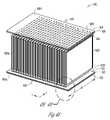
- FIG. 4Aillustrates an isometric view of a battery pack including a plurality of electrical cells, according to some embodiments.
- FIG. 4Billustrates an enlarged view of “ 4 B” in FIG. 4A .
- FIG. 5illustrates a method of constructing a battery pack, according to some embodiments.
- FIG. 6illustrates a method of controlling the temperature of a battery pack, according to some embodiments.
- FIG. 7illustrates a method of conducting heat out of a battery pack, according to some embodiments.
- FIG. 1shows a vehicle system 100 , according to one embodiment of the present subject matter.
- the vehicle 102is an electric vehicle and includes a vehicle propulsion battery 108 and at least one propulsion motor 106 for converting battery energy into mechanical motion, such as rotary motion.
- Various batteriesare contemplated.
- the present subject matterincludes embodiments in which the battery 108 is a secondary battery that is rechargeable using electricity rather than chemicals or other materials.
- Various secondary battery chemistriesare contemplated, including lithium ion chemistries such as lithium polymer, lithium iron phosphate, nickel metal hydride, lead acid, and other chemistries.
- the present subject matterincludes examples in which the vehicle propulsion battery 108 is a subcomponent of an energy storage system (“ESS”).
- the battery 108includes a battery pack that includes a plurality of electrical cells.
- the battery 108can include a plurality of battery packs.
- An ESSincludes various components associated with transmitting energy to and from the vehicle propulsion battery 108 , including, but not limited to, safety components, cooling components, heating components, rectifiers and combinations thereof.
- the present subject mattershould not be construed to be limited to the configurations disclosed herein, as other configurations of a vehicle propulsion battery 108 are possible.
- the battery 108includes one or more electrical cells in various examples.
- the battery 108includes a plurality of lithium ion cells coupled in parallel and/or series.
- a battery packincludes multiple flat electrical cells in a stack, positioned perpendicular to their major surfaces.
- a battery packincludes a plurality of electrical cells stack and structures to electrically and physically interconnect the electrical cells.
- a battery packincludes a stack of electrical cells that are interconnected in parallel with one or more busbars or collector plates.
- a battery packcan optionally include a housing for the stack of electrical cells.
- Several battery packscan optionally be connected in parallel or series, by electrically connecting multiple collector plates of multiple battery packs.
- a flat cellis an object having major first and second surfaces that are generally parallel to one another.
- the thickness of the flat cellis the distance between the first and second major surfaces. This thickness is generally smaller than the perimeter dimensions of either of the first or second major surfaces.
- a stackrefers to a configuration of cells, such that the cells are placed onto one another in alignment.
- each of the cellshas a perimeter, and each of these perimeters is substantially coextensive.
- Some examplesinclude a first plurality of cells connected in parallel to define a first battery pack, with a second plurality of cells connected in parallel to define a second battery pack, with the first pack and the second pack connected in series.
- the stackincludes around 2 to 3 cells.
- a city caris a car that has a smaller size and a limited range requirement.
- One example of a city caris a car that is between around 3.4 meters and 3.6 meters long.
- Some city car examplesare required to travel at least 40 miles before recharge is required.
- Some stacksare configured for use in a typical passenger car. This is a car that is longer than a city car.
- the packcan include up to 8 cells coupled electrically in parallel.
- the cells for the car sizes discussed hereare adapted to store about 73 watt-hours of energy, although other energy levels are possible.
- Battery voltage, and consequently, pack voltageoften ranges from around 4.2 volts to about 2.8 volts in use. In part because the voltage of batteries ranges from cell to cell, some instances include voltage management systems to maintain a steady voltage. Some embodiments connect 9 battery packs in series to define a module. Such a module has around 35 volts. Some instances connect 11 modules in series to define the battery of the ESS. The ESS will demonstrate around 400 volts in various examples.
- the ESSmay include a state of charge circuit to monitor the state of charge of the battery 108 .
- the state of charge circuitcan count coulombs, watt-hours, or provide other measure of how much energy is in the battery 108 .
- the state of chargeis determined by measuring the battery voltage either open circuited or driving a known load.
- the state of charge circuitcould optionally provide additional battery information, such as temperature, rate of energy use, number of charge/discharge cycles, and other information relating to battery state.
- the PEM 104is part of a system which converts energy from the vehicle propulsion battery 108 into energy useable by the at least one propulsion motor 106 .
- the energy flowis from the at least one propulsion motor 106 to the vehicle propulsion battery 108 .
- the vehicle propulsion battery 108transmits energy to the PEM 104 , which converts the energy into energy usable by the at least one propulsion motor 106 to propel the electric vehicle.
- the at least one propulsion motor 106generates energy that is transmitted to the PEM 108 .
- the PEM 108converts the energy into energy which can be stored in the vehicle propulsion battery 108 .
- the energy converter 104includes transistors. Some examples include one or more field effect transistors. Some examples include metal oxide semiconductor field effect transistors. Some examples include one more insulated gate bipolar transistors.
- the PEM 108may include a switch bank which is configured to receive a direct current (“DC”) power signal from the vehicle propulsion battery 108 and to output a three-phase alternating current (“AC”) signal to power the vehicle propulsion motor 106 . In some examples, the PEM 108 may be configured to convert a three phase signal from the vehicle propulsion motor 106 to DC power to be stored in the vehicle propulsion battery 108 . Some examples of the PEM 108 convert energy from the vehicle propulsion battery 108 into energy usable by electrical loads other than the vehicle propulsion motor 106 . Some of these examples switch energy from approximately 390 Volts DC to 14 Volts DC.
- the propulsion motor 106may be a three phase AC induction motor. Some examples include a plurality of such motors.
- the present subject mattercan optionally include a transmission or gearbox 110 in certain examples. While some examples include a 1-speed transmission, other examples are contemplated. Manually clutched transmissions are contemplated, as are those with hydraulic, electric, or electrohydraulic clutch actuation. Some examples employ a dual-clutch system that, during shifting, phases from one clutch coupled to a first gear to another coupled to a second gear. Rotary motion is transmitted from the transmission 110 to wheels 112 via one or more axles 114 , in various examples.
- a vehicle management system 116is optionally provided which provides control for one or more of the vehicle propulsion battery 108 and the PEM 104 .
- the vehicle management system 116is coupled to vehicle system which monitors a safety system such as a crash sensor.
- the vehicle management system 116is coupled to one or more driver inputs, such as acceleration inputs.
- the vehicle management system 116is configured to control power to one or more of the vehicle propulsion battery 108 and the PEM 108 , in various embodiments.
- a temperature control system 150is to control the temperature of the battery 108 , and may heat or cool the battery.
- the temperature control systemcan optionally control the temperature of the PEM 104 and/or the motor 106 .
- the temperature control system 150is pictured as one component (i.e., the cooling system of components 104 , 106 and 108 is integrated), embodiments are possible in which each of the battery 108 , the PEM 104 and the motor 106 has an individual temperature control system. Integrated temperature control systems that control the temperature of two of these components are possible.
- Some embodimentsinclude a fin system that can control temperature using convection. Additional embodiments include a refrigeration system and conduct heat from the battery 108 using circulating liquid.
- a refrigeration system of the temperature control system 150includes a compressor powered by an electric motor that is powered by the battery 108 .
- Some embodimentsinclude a heating system to heat the battery 108 .
- the heating systemincludes electric heating elements that are powered by the battery 108 .
- Battery heatingis useful to heat a battery when the ambient temperature is cool such that the battery is below a predetermined temperature.
- the temperature control system 150can optionally cool or warm a cabin 158 of the vehicle 100 , such as by blowing cooled or warmed air through one or more ducts such as duct 154 . Temperature control of the cabin 158 can occur concurrent to controlling the temperature of the power train components of the vehicle, including, but not limited to, the PEM 104 , the motor 106 and the ESS 108 .
- the temperature control system 150includes a heat exchanger 152 external to the cabin 158 for shedding heat.
- This heat exchanger 152is coupled to other portions of the temperature control system 150 via coolant tubes 156 and 156 ′.
- This heat exchanger 152can be a part of a refrigeration system, or it can be a fluid cooling system that circulates fluid to cool one or more of the power train components.
- the temperature control system 150absorbs heat from the battery 108 .
- the temperature control system 150includes one or more cooled panels that touch the battery 108 and which cool the battery 108 by directing fluid that is cooler than the electrical cells through the panels and by the electrical cells of the battery 108 so that heat is conducted out of the electrical cells and into the fluid of the temperature control system 150 .
- External power 118is provided to the PEM 104 , in various examples.
- the PEM 104converts energy into energy that can be stored by the battery 108 .
- external power 118includes a charging station that is coupled to a municipal power grid.
- the charging stationconverts power from a 110V AC power source into power storable by the vehicle propulsion battery 108 .
- the charging stationconverts power from a 120V AC power source into power storable by the vehicle propulsion battery 108 .
- Some embodimentsinclude converting energy from the battery 108 into power usable by a municipal grid using the PEM 104 to convert energy.
- the present subject matteris not limited to examples in which a converter for converting energy from an external source to energy usable by the vehicle 100 is located outside the vehicle 100 , and other examples are contemplated.
- the vehicle display system 126includes a visual indicator of system 100 information in some examples.
- the vehicle display system 126includes a monitor that includes information related to system 100 .
- the vehicle display system 126can include information relating to vehicle state of charge.
- FIG. 2Aillustrates a top view of an electrical cell 200 , according to some embodiments.
- FIG. 2Billustrates a side view of the electrical cell of FIG. 2A .
- the electrical cell 200is an electrochemical battery. It is variously referred to as a pouch cell or a flat cell.
- the electrical cell 200includes an electrode stack or bank 202 sandwiched between a first 204 and second 206 electrical cell housing layer. An electrically and heat conductive tab 208 extends through the housing 210 .
- the electrode bank 202includes at least one anode and at least one cathode. Between the anode and the cathode is a separator that physically and electrically isolates the anode and the cathode from one another.
- the electrode bank 202includes an anode ribbon and a cathode ribbon that are folded into the electrode bank 202 . Accordingly, a cross section of the bank taken through the fold lines would show a zig-zag pattern.
- the electrode bank 202includes a plurality of individual or separate anode layers and individual or separate cathode layers. In these embodiments, the electrode bank 202 does not include folding of the anode layers or the cathode layers. For example, a pick and place process can stack an anode layer, then a separator layer onto the anode layer, and then a cathode onto the separator layer. This process can repeat to build up the electrode bank 202 . The process can optionally align layers of the electrode bank 202 so that the perimeters along the layer edges are coextensive with one another.
- a layer of the bank 202is rectangular and has a pair of major surfaces and an edge that extends between the pair of major surfaces, the edge being small in relation to either of length or width dimensions of the major surfaces.
- Banks that are not rectangularare also possible.
- Other electrode bank configurationsare possible and can be used with the present subject matter.
- capacitors and power sources that are hybridincluding but not limited to fast charging batteries that charge nearly as quickly as capacitors, can be used with the present subject matter.
- the electrode bank 202is positioned in housing 210 .
- the housing 210includes a generally hexahedral shape with first 218 and second 220 major surfaces being approximately parallel with an edge 216 extending between the first 218 and second 220 major surfaces.
- the housing 210includes first 204 and second 206 electrical cell housing layers. These are joined together in a seam 212 .
- the seam 212includes abutting faces of the first 204 and second 206 electrical cell housing layers. This abutment encircles the electrode bank 202 and defines a flange 214 .
- the tab 208Extending through the flange 214 and the seam 212 and between the first 204 and second 206 electrical cell housing layers is the tab 208 .
- the tab 208extends away from a housing edge 216 of the housing 210 . Additional configurations include, but are not limited to, those in which the tab extends through a sealed aperture in one of the electrical cell housing layers 204 , 206 , the seal being at least restrictive enough to restrict the flow of electrical cell electrolyte.
- the tab 208is connected to at least one electrode of the electrode bank 202 .
- the tab 208abuts one or more electrodes and is welded, soldered or otherwise connected to the electrode. In some examples, the tab 208 is bent so that it can extend along the edge 217 of the electrode bank 202 .
- the tab 208is heat conductive and the one or more electrodes to which the tab 208 is connected are heat conductive. These electrodes are substantially more conductive than the separator and electrolyte of the electrical cell 200 . Accordingly, heat conduction in the D 1 direction is substantially larger than heat conduction in the D 2 direction. Using the tab 208 to conduct heat takes advantage of this.
- cell 200uses electrical cell housing layers 204 and 206 that are generally flexible. Although these layers are thermally conductive, conducting heat from the electrode bank 202 through the electrical cell housing layers 204 , 206 and then cooling those layers with heat radiation or convection provides an insufficient amount of cooling. This is especially so in embodiments in which the electrical cell 200 is positioned in a further housing that is sealed to restrict the flow of air into and out of the further housing.
- the material of the electrical cell housing layers 204 and 206is a thermoplastic polymer. In some examples, it is capable of being heat sealed to itself. Materials possible include, but are not limited to, polyethylene, polypropylene, PVC, nylon, FEP, and PFA. The thickness of the material can vary. In some examples, it is approximately 0.002 inches thick.
- the sealed first 204 and second 206 electrical cell housing layersdefine an interior that is sealed. In various embodiments, the interior is filled with electrolyte.
- the housing edge 216refers to the any of the surfaces that are not the major surfaces 218 or 220 of the housing.
- An optional tab 222can be positioned along edge 216 and connected to an electrode. This tab 222 can be similarly sized to the other tab 208 , but the present subject matter is not so limited.
- This second tab 222can extend through the housing 210 via the seam 212 and away from the housing 210 , although other configurations are possible.
- the first tab 208 and a second tab 222may be used as terminals for different poles of the electrical cell 200 .
- the tab 208can be connected to an anode and the tab 222 can be connected to a cathode.
- the dimension W Brefers to a width of the electrical cell 200 .
- the dimension L Brefers to the length of the electrical cell 200 .
- the dimension T Brelates to the thickness of the electrical cell 200 .
- the dimensions as diagrammedreflect the thickness of the bank 202 and the housing portions 204 and 206 , but discount the flange in measuring length L B and width W B .
- the width W B of the electrical cellis 216 millimeters
- the length L B of the electrical cellis 129 millimeters
- the thickness T B of the electrical cellis 7.4 millimeters.
- the length L B and the width W B of the electrical cellare substantially larger than the thickness T B of the electrical cell.
- the width of the electrical cellis approximately 30 times the thickness of the electrical cell, and the length of the electrical cell is approximately 17 times the thickness of the electrical cell.
- Various electrical cells 200 having this sizehave a capacity of approximately 20.5 amp-hours. Some have an energy of 72 watt-hours.
- the first tab 208has a width of W T1 , a length of L T1 , and a thickness of T T1 .
- the second tab 218has a width of W T2 , a length of L T2 , and a thickness of T T2 .
- Various materialsare used for one or both of the tabs, including, but not limited to, copper, aluminum and alloys thereof.
- the tabis coupled to one or more electrodes of the bank 202 so that the tab conducts both electricity and a substantial amount of heat from the bank 202 and out of the housing 210 .
- the tab 208is sized to conduct a substantial amount of heat away from the electrode bank 202 .
- FIG. 3illustrates a side view of the electrical cell 200 and includes diagrammatic symbols that illustrates thermal conductivity values of electrical cell 200 and some additional structures 302 , 304 .
- the tab 208may be sized so that it is larger than a tab required to fulfill the electrical charging and discharging needs the electrical cell 200 .
- the normal charge rate of the electrical cell 200is its capacity divided by 3. This is over one hour. This charge rate is termed “C/3”.
- the discharge rateis the capacity of the electrical cell 200 depleted over one hour. This is “1C”.
- the electrical resistance of tab 208should be small compared to the DC impedance of the electrical cell 200 .
- An example tab 208may have a resistance that is 10% of the electrical resistance of the electrical cell 200 and can be as low as 1% or lower.
- the cell 200has an electrical resistance of approximately 5.8 milliohms.
- the electrical resistance of the tabis given in equation 1.
- Rrepresents the electrical resistance of the tab 208 .
- “l”represents the length of the tab.
- “ ⁇ ”represents the resistivity of the tab 208 .
- A”represents the cross sectional area of the tab 208 , (i.e. W T1 *T T1 ).
- a tab 208 of copper at 20 degrees Celsiushas a resistivity of approximately 1.72 E-8 ohm meters.
- the tabhas a resistance of approximately 9.5 E-4 milliohms. This is a small fraction of the resistance of the electrical cell 200 . Accordingly, tab 208 having these dimensions is sufficiently conductive to facilitate the discharge of the electrical cell 200 . Even a doubling of area “A” would not affect the ratio of resistances between the electrical cell 200 and the tab 208 greatly.
- the mechanical requirements of the tab 208constrain its size, as a tab that was sized to fulfill a minimum level of conductivity would be subject to ripping or breaking in use. As yet designers have not designed tabs with the constraint that they are sized to remove a substantial amount of heat from the electrical cell 200 .
- R TOTAL — THERMALR INPLANE +R TAB +R PANEL +R TIM .
- R TOTAL — THERMALis the thermal resistance of a battery system thermal conduction path away from the electrical cell 200 .
- Example units for thermal resistanceare degrees Celsius per watt.
- R INPLANEis the resistance to thermal conduction along axis D 2 .
- R TABis the thermal resistance of the tab 208 .
- R PANELis the resistance of a busbar or collector panel 302 to which tab 208 is connected to. The connections between the tab 208 and the collector panel 302 can be through ultrasonic welds or other connections.
- R TIMis the thermal resistance of a thermal interface material 304 confronting the collector panel 302 .
- the collector panel 302includes a surface 307 that faces a surface 305 of the thermal interface material 304 .
- the collector panel 302 and the thermal interface material 304need not touch. In these cases, convection or radiation would be relied on for temperature control. However, in some embodiments, the thermal interface material 304 abuts the collector panel 302 .
- a thermal interface layermay comprise a relatively thin layer of material. This material can be a solid, grease, or liquid.
- a thermal interface layerhas a high heat conductivity but a low electrical conductivity. In some examples, it is a dielectric.
- An example thermal interface materialincludes a ceramic-filled silicone rubber. Some examples include alumina-filled silicone rubber with a thermal conductivity of 1 W/mK.
- An alternative example thermal interface materialincludes a thermal grease, which is also termed thermal compound, heat paste, heat transfer compound, thermal paste, or heat sink compound. Thermal grease can use one or more different thermally conductive substances. Ceramic-based thermal grease has favorable thermal conductivity and may be composed of a ceramic powder suspended in a liquid or gelatinous silicone compound.
- Some examples and their thermal conductivities in units of W/m ⁇ Kare: beryllium oxide, 218, aluminum nitride, 170, aluminum oxide, 39, zinc oxide, 21, and silicon dioxide, 1.
- Metal-based thermal greasesmay contain metal particle. Carbon based materials may use diamond powder or short carbon fibers. Liquid metal based may be formed of liquid metal alloys such as gallium. Various compounds use silicone grease as a medium, which is a favorable heat conductor, though some embodiments use mineral oil.
- the amount of heat that is being produced by electrical cell 200 in useis predetermined by its application. For example, in a vehicle, the amount of heat produced is understood after designers design and test the vehicle. The heat produced over the course of a one-hour discharge can be approximated by the one-hour discharge current of the electrical cell 200 squared multiplied by the electrical impedance of the electrical cell 200 .
- An applicationmay require that the temperature at the surface 306 of the thermal interface material 304 be a predetermined temperature that is within a range specified for use. This range can be specified by a standards organization or by another party such as a manufacture of automobiles.
- the difference between the temperature of the electrical cell 200 and the surface 306is expressed as ⁇ T. Using this input, it is possible to determine the thermal resistance desired for a conductive path extending from an electrical cell. This can be expressed as:
- R TARGET( ⁇ ⁇ ⁇ T CURRENT 2 ⁇ IMPEDANCE ⁇ ) . ( 3 )
- the thermal resistance of the tabcan be expressed as:
- R TAB ⁇( L T ⁇ ⁇ 1 k TAB ⁇ T T ⁇ ⁇ 1 ⁇ W T ⁇ ⁇ 1 ) . ( 6 )
- the tab 208has a ratio between a cross sectional area (i.e., T T1 *W T1 ) perpendicular to a length L T1 of the tab and the length L T1 that is significantly larger than a further ratio of cross sectional area perpendicular to length to length sized to conduct electrical energy, that is to have an electrical resistance as discussed above, at a rate required by a maximum charge or discharge rate of the electrical cell. Since the tab 208 can easily meet the requirements of electrical conduction, the size of the tab is selected based on the ⁇ T that is required. If the longer tab is used, a greater cross sectional area is required, and so on.
- one or both of the tabs 208 and 222have a mass that is substantially larger than a mass required to conduct current at a predetermined maximum cell electrical discharge rate.
- This masscan be at least 10% larger and up to or exceeding 100% larger.
- the tabcan be formed of a material with an improved thermal and/or electrical conductivity that than required to conduct current at a predetermined maximum cell discharge rate.
- the electrical cell 200has varying thermal conductivity properties. It is non-isotropic in some embodiments. In some examples, the thermal conductivity in plane, along axis D 1 , is smaller than the thermal conductivity along axis D 2 . In some examples, the conductivity along D 1 is approximately 1.2 watts per meter Kelvin. In some examples, the conductivity along D 2 is approximately 25 W per meter Kelvin.
- the present subject mattertakes advantage of the non-isotropic nature of the cell by conducting heat along an axis that has maximum heat conductivity.
- the tab 208has a higher volumetric energy density than a panel that is abutting one of the major surfaces 218 , 220 of the electrical cell 200 and has a length and a width that is coextensive with the length and the width of the electrical cell 200 (i.e., not including the flange 214 ).
- a tab 208 that is copper and that has dimensions of 0.0005 meters by 0.01 meters by 0.180 metershas an approximately 13.5% improved volumetric energy density over a plane contacting one of the major surfaces of the electrical cell 200 , the plane having dimensions of 0.129 meters by 0.007 meters by 0.216 meters.
- the improvement in gravimetric energy densityis approximately 15.0%.
- the tab approach to removing heat using thermal conductionoutperforms a panel embodiment in which a temperature control panel is touching one of the major surfaces 218 , 220 of the electrical cell.
- FIG. 4Aillustrates an isometric view of a battery pack including a plurality of electrical cells, according to some embodiments.
- FIG. 4Billustrates an enlarged view of the portion of FIG. 4A labeled “ 4 B”.
- Individual electrical cells 402 A, . . . , 402 Yare shown arranged in a stack.
- the cells of FIGS. 2A , 2 B and 3are compatible with the examples of FIGS. 4A and 4B . Although 25 cells are illustrated, other numbers are possible.
- the cellsare similarly-shaped electrical cells.
- Each of the cellsincludes at least one electrically and thermally conductive tab 404 A, . . . , 404 Y coupled to the at least one electrode of the cell.
- . . , 404 Yconduct both current and a substantial amount of heat out of a housing of the cell.
- a first set of tabs 404 A, . . . , 404 Yis aligned on one side 406 of the battery pack, and a second set of tabs 408 A, . . . , 408 Y is aligned on a second side 410 .
- Heat conductionis shown at 411 .
- Current conductionis shown at 413 .
- the flat housings of the electrical cells 402 A, . . . , 402 Yare spaced apart from one another with air gaps.
- the battery packincludes an electrically and heat conductive collector panel 412 .
- the tabs 404 A, . . . , 404 Yare folded and are coupled to the collector panel 412 .
- the collector panelincludes a first planar surface 414 electrically and thermally coupled to each of the tabs.
- the collector panel 412additionally includes a second surface 416 opposite the first surface 414 .
- the collector panel 412can be metallic and can be formed of copper and its alloys, aluminum and its alloys, combinations thereof, or other metals or electrically and thermally conductive materials.
- the battery pack 400additionally includes a thermal interface material 418 that is electrically insulative and thermally conductive.
- the thermal interface materialincludes a first surface 420 in thermal contact with the second surface 416 of the collector panel.
- the thermal interface material 418additionally includes a second surface 422 in contact with a temperature control panel that is in thermal contact with an external temperature control system.
- a second set of tabs 408 A, . . . , 408 Yis shown coupled to a second collector panel 424 , a second thermal interface material 426 and a second temperature control panel 428 .
- the temperature control panels 423 and 428are in fluid communication with a temperature control system such as the system 150 disclosed in FIG. 1 .
- the temperature control systems contemplatedmay circulate fluid that is at a specified temperature. In some examples, the fluid is at an ambient temperature.
- the temperature control panel 423is heated or cooled by fluid that is one temperature as set by the temperature control system 150 .
- the temperature differential between the temperature control panel 423 and the thermal interface material 418causes heat to flow toward or away from the collector panel 412 .
- the collector panel 412has low thermal resistance and conducts heat with the tabs 404 A, . . . , 404 Y and causes them to be heated or cooled.
- the temperature control systemcan circulate fluid to heat or cool the temperature control panel 423 .
- the temperature control panelis a panel defining a series of lumens.
- the temperature control panelis a panel with a plurality of heat conductive tubes coupled to the panel, such as by welding, soldering or the like.
- the temperature control paneldefines a temperature control path 450 extending along the width W of the tabs 404 A, . . . , 404 Y. In some of these embodiments, at least one temperature control path 450 is bisected by the plane 452 of a tab.
- FIG. 5illustrates a method of constructing a battery pack, according to some embodiments.
- the methodincludes stacking a plurality of flat electrical cells into a stack.
- the methodincludes determining the heat produced by a stack of flat electrical cells during discharge of the plurality of flat electrical cells at a specified discharge rate.
- the methodincludes coupling the plurality of flat electrical cells to a current collector via respective tabs, with each tab including a respective length and a respective cross sectional area perpendicular to the length selected so that the temperature differential between the current collector and the plurality of flat electrical cells is below a threshold.
- FIG. 6illustrates a method of constructing a battery pack temperature control system, according to some embodiments.
- the methodincludes stacking a plurality of electrical cells into a stack, with each electrical cell coupled to a respective tab, with the respective tabs aligned along one side of the stack.
- the methodincludes coupling the respective tabs to a current collector.
- the methodincludes sandwiching a thermally insulative material between the current collector and a temperature control panel.
- the methodincludes temperature control of the temperature control panel.
Landscapes
- Engineering & Computer Science (AREA)
- Manufacturing & Machinery (AREA)
- Chemical & Material Sciences (AREA)
- Chemical Kinetics & Catalysis (AREA)
- Electrochemistry (AREA)
- General Chemical & Material Sciences (AREA)
- Automation & Control Theory (AREA)
- Secondary Cells (AREA)
- Battery Mounting, Suspending (AREA)
- Connection Of Batteries Or Terminals (AREA)
Abstract
Description
RTOTAL
wherein RTOTAL
RTOTAL
wherein kTABis the thermal conductivity of the
Claims (14)
Priority Applications (5)
| Application Number | Priority Date | Filing Date | Title |
|---|---|---|---|
| US12/259,881US8153290B2 (en) | 2008-10-28 | 2008-10-28 | Heat dissipation for large battery packs |
| EP20090174243EP2226870B1 (en) | 2008-10-28 | 2009-10-27 | Improved heat dissipation for large battery packs |
| JP2009246487AJP2010108932A (en) | 2008-10-28 | 2009-10-27 | Improved heat dissipation for large-sized battery pack |
| AT09174243TATE550796T1 (en) | 2008-10-28 | 2009-10-27 | IMPROVED HEAT DISSIPATION FOR LARGE BATTERY PACKS |
| US13/410,339US8968949B2 (en) | 2008-10-28 | 2012-03-02 | Method of withdrawing heat from a battery pack |
Applications Claiming Priority (1)
| Application Number | Priority Date | Filing Date | Title |
|---|---|---|---|
| US12/259,881US8153290B2 (en) | 2008-10-28 | 2008-10-28 | Heat dissipation for large battery packs |
Related Child Applications (1)
| Application Number | Title | Priority Date | Filing Date |
|---|---|---|---|
| US13/410,339DivisionUS8968949B2 (en) | 2008-10-28 | 2012-03-02 | Method of withdrawing heat from a battery pack |
Publications (2)
| Publication Number | Publication Date |
|---|---|
| US20100104935A1 US20100104935A1 (en) | 2010-04-29 |
| US8153290B2true US8153290B2 (en) | 2012-04-10 |
Family
ID=42117831
Family Applications (2)
| Application Number | Title | Priority Date | Filing Date |
|---|---|---|---|
| US12/259,881Active2031-02-09US8153290B2 (en) | 2008-10-28 | 2008-10-28 | Heat dissipation for large battery packs |
| US13/410,339Active2029-01-09US8968949B2 (en) | 2008-10-28 | 2012-03-02 | Method of withdrawing heat from a battery pack |
Family Applications After (1)
| Application Number | Title | Priority Date | Filing Date |
|---|---|---|---|
| US13/410,339Active2029-01-09US8968949B2 (en) | 2008-10-28 | 2012-03-02 | Method of withdrawing heat from a battery pack |
Country Status (4)
| Country | Link |
|---|---|
| US (2) | US8153290B2 (en) |
| EP (1) | EP2226870B1 (en) |
| JP (1) | JP2010108932A (en) |
| AT (1) | ATE550796T1 (en) |
Cited By (10)
| Publication number | Priority date | Publication date | Assignee | Title |
|---|---|---|---|---|
| US20110189524A1 (en)* | 2010-01-29 | 2011-08-04 | Renault S.A.S. | Battery pack for an electric powertrain vehicle |
| US20120188714A1 (en)* | 2009-04-24 | 2012-07-26 | Von Borck Felix | Battery management system |
| US8725330B2 (en) | 2010-06-02 | 2014-05-13 | Bryan Marc Failing | Increasing vehicle security |
| US20140333132A1 (en)* | 2011-12-26 | 2014-11-13 | Hitachi, Ltd. | Battery System |
| US9537127B2 (en) | 2014-11-12 | 2017-01-03 | Ford Global Technologies, Llc | Low profile battery assembly for electrified vehicles |
| WO2017037597A1 (en)* | 2015-08-28 | 2017-03-09 | Tata Motors European Technical Centre Plc | Coated substrate and method of fabrication thereof |
| US10243186B2 (en) | 2015-03-06 | 2019-03-26 | Ttb Holding Company Limited | Battery module with thermal runaway and gas exhaust management system |
| US10446887B2 (en) | 2014-07-21 | 2019-10-15 | Ford Global Technologies, Llc | Battery thermal management system including thermal interface material with integrated heater element |
| US10770744B2 (en) | 2015-02-18 | 2020-09-08 | Sterling PBES Energy Solution Ltd. | Lithium ion battery module with cooling system |
| US11289746B2 (en) | 2016-05-03 | 2022-03-29 | Bosch Battery Systems Llc | Cooling arrangement for an energy storage device |
Families Citing this family (59)
| Publication number | Priority date | Publication date | Assignee | Title |
|---|---|---|---|---|
| US8663828B2 (en)* | 2009-04-30 | 2014-03-04 | Lg Chem, Ltd. | Battery systems, battery module, and method for cooling the battery module |
| US8974942B2 (en) | 2009-05-18 | 2015-03-10 | Gentherm Incorporated | Battery thermal management system including thermoelectric assemblies in thermal communication with a battery |
| US8703318B2 (en)* | 2009-07-29 | 2014-04-22 | Lg Chem, Ltd. | Battery module and method for cooling the battery module |
| DE102010018289A1 (en)* | 2010-04-26 | 2011-10-27 | Continental Automotive Gmbh | Energy storage cell |
| DE102010028191A1 (en)* | 2010-04-26 | 2011-10-27 | Robert Bosch Gmbh | Battery with a cooling plate and motor vehicle with a corresponding battery |
| DE102010021148B4 (en) | 2010-05-21 | 2024-10-24 | Dr. Ing. H.C. F. Porsche Aktiengesellschaft | Pouch cell battery assembly and corresponding manufacturing method and use |
| US8563159B2 (en)* | 2010-08-04 | 2013-10-22 | Bren-Tronics Batteries International, L.L.C. | Structure and method for removing battery cell heat |
| JP2012054001A (en) | 2010-08-31 | 2012-03-15 | Nitto Denko Corp | Heat dissipation housing, lithium battery pack using the same, and semiconductive tape for heat dissipation |
| US8803477B2 (en)* | 2010-09-21 | 2014-08-12 | Electricab Corporation | Battery module for high-current rapid charging |
| DE112012002935T5 (en) | 2011-07-11 | 2014-05-15 | Gentherm Inc. | Thermoelectric based thermal management of electrical devices |
| US9007027B2 (en)* | 2012-01-31 | 2015-04-14 | Green Charge Networks Llc | Charge management for energy storage temperature control |
| US9263901B2 (en) | 2012-05-19 | 2016-02-16 | Tesla Motors, Inc. | Secondary service port for high voltage battery packs |
| US20130344359A1 (en)* | 2012-06-26 | 2013-12-26 | Enerdel, Inc. | Modular energy storage system |
| DE102012213273B4 (en)* | 2012-07-27 | 2021-08-05 | Hydac Technology Gmbh | Energy storage device |
| JP5725064B2 (en)* | 2012-09-21 | 2015-05-27 | トヨタ自動車株式会社 | Electric vehicle |
| KR101417411B1 (en)* | 2012-11-16 | 2014-07-09 | 기아자동차주식회사 | Battery for vehicle and vehicle comprising the same |
| US9196878B2 (en)* | 2012-11-20 | 2015-11-24 | GM Global Technology Operations LLC | Stackable cartridge module design |
| DE112014000419T5 (en) | 2013-01-14 | 2015-10-15 | Gentherm Incorporated | Thermoelectric based thermal management of electrical devices |
| US10270141B2 (en) | 2013-01-30 | 2019-04-23 | Gentherm Incorporated | Thermoelectric-based thermal management system |
| US20140234668A1 (en)* | 2013-02-19 | 2014-08-21 | Faster Faster, Inc. | Battery Housing with Single-Side Electrical Interconnects |
| DE102013220171A1 (en)* | 2013-10-07 | 2015-04-09 | Robert Bosch Gmbh | Battery cell and manufacturing process for this, as well as battery |
| WO2015066079A1 (en) | 2013-10-29 | 2015-05-07 | Gentherm Incorporated | Battery thermal management with thermoelectrics |
| US9343720B2 (en) | 2014-08-05 | 2016-05-17 | Apple Inc. | Pre-treating separator to enable separator for pick and place operation |
| CN106717139B (en) | 2014-09-12 | 2019-07-12 | 詹思姆公司 | Graphite thermoelectric and/or resistive thermal management systems and methods |
| JP2016081579A (en)* | 2014-10-10 | 2016-05-16 | 株式会社日立製作所 | Secondary battery system |
| US10147984B2 (en)* | 2015-07-31 | 2018-12-04 | SynCells, Inc. | Portable and modular energy storage for multiple applications |
| WO2017043889A1 (en)* | 2015-09-08 | 2017-03-16 | 주식회사 엘지화학 | Battery module having improved cooling performance |
| US10109829B2 (en) | 2015-11-05 | 2018-10-23 | Ford Global Technologies, Llc | Support assembly for traction battery |
| WO2017106524A1 (en) | 2015-12-15 | 2017-06-22 | Crynamt Management Llc | Microporous insulators |
| US10497997B2 (en) | 2016-03-14 | 2019-12-03 | Ford Global Technologies, Llc | Assembly and method to maintain clearance to a thermal fin within a battery assembly |
| WO2017163336A1 (en)* | 2016-03-23 | 2017-09-28 | 三菱電機株式会社 | Storage battery module |
| EP3316391B1 (en)* | 2016-10-26 | 2021-05-19 | Samsung SDI Co., Ltd. | Battery system, base plate for a battery system and electric vehicle |
| KR102155330B1 (en)* | 2016-11-29 | 2020-09-11 | 주식회사 엘지화학 | Air cooling type secondary battery module |
| EP3339085B1 (en)* | 2016-12-20 | 2019-06-19 | Nexans | Assembly for supplying power to a motor vehicle with an electric motor |
| EP3413393A1 (en)* | 2017-06-07 | 2018-12-12 | Robert Bosch GmbH | Electrode assembly for a battery module |
| US10203738B2 (en) | 2017-06-13 | 2019-02-12 | SynCells, Inc. | Energy virtualization layer for commercial and residential installations |
| US11271766B2 (en) | 2017-06-13 | 2022-03-08 | SynCells, Inc. | Energy virtualization layer with a universal smart gateway |
| US11125461B2 (en) | 2017-06-13 | 2021-09-21 | Gerard O'Hora | Smart vent system with local and central control |
| US11394573B2 (en) | 2017-06-13 | 2022-07-19 | SynCells, Inc. | Energy virtualization layer with a universal smart gateway |
| US10818903B1 (en) | 2017-08-15 | 2020-10-27 | Apple Inc. | Polypropylene carbonate and catalysts |
| US11233782B2 (en) | 2017-10-04 | 2022-01-25 | Resilience Magnum IP, LLC | Single node network connectivity for structure automation functionality |
| US11121419B2 (en)* | 2017-10-11 | 2021-09-14 | Resilience Magnum IP, LLC | Battery heat management |
| KR102415726B1 (en)* | 2017-10-16 | 2022-06-30 | 주식회사 엘지에너지솔루션 | Battery Cell with Fluid Material Coated on Surface of Battery Case |
| US10850713B2 (en) | 2017-10-20 | 2020-12-01 | SynCells, Inc. | Robotics for rotating energy cells in vehicles |
| US11391784B2 (en) | 2018-06-27 | 2022-07-19 | General Atomics | Single cell fault tolerant battery system architecture |
| EP3595078A1 (en) | 2018-07-12 | 2020-01-15 | Nederlandse Organisatie voor toegepast- natuurwetenschappelijk onderzoek TNO | Electrode for use in a layered device structure, as well as a battery device |
| CN113167510B (en) | 2018-11-30 | 2025-10-03 | 金瑟姆股份公司 | Thermoelectric regulation system and method |
| KR102549437B1 (en) | 2018-11-30 | 2023-06-28 | 주식회사 엘지에너지솔루션 | Electrode assembly and secondary battery including the same |
| KR102442035B1 (en) | 2018-11-30 | 2022-09-07 | 주식회사 엘지에너지솔루션 | Secondary battery and device including same |
| US20220085449A1 (en)* | 2019-01-18 | 2022-03-17 | Dai Nippon Printing Co., Ltd. | Electricity storage device, electric-powered vehicle, and mehtod of manufacturing an electricity storage device |
| JP7115350B2 (en)* | 2019-02-12 | 2022-08-09 | トヨタ自動車株式会社 | stacked battery |
| US11152557B2 (en) | 2019-02-20 | 2021-10-19 | Gentherm Incorporated | Thermoelectric module with integrated printed circuit board |
| CN110098429B (en)* | 2019-03-22 | 2021-11-26 | 华为数字能源技术有限公司 | Battery, power utilization device and battery core installation method |
| US11670813B2 (en)* | 2019-04-01 | 2023-06-06 | Applied Thermoelectric Solutions, LLC | Electrically insulative and thermally conductive parallel battery cooling and temperature control system |
| US11646461B2 (en)* | 2020-03-17 | 2023-05-09 | The Boeing Company | Battery cooling systems and methods |
| US20230060754A1 (en)* | 2020-03-26 | 2023-03-02 | Ddp Specialty Electronics Materials Us, Llc | Thermal interface material comprising multimodally distributed spherical fillers |
| WO2022051642A1 (en)* | 2020-09-04 | 2022-03-10 | Romeo Power, Inc. | Systems and methods for battery tab cooling |
| EP4270599A4 (en)* | 2021-04-06 | 2024-11-13 | Nippon Steel Corporation | COOLING STRUCTURE BETWEEN BATTERY CELLS, BATTERY MODULE AND BATTERY PACK |
| CN114361656B (en)* | 2021-12-29 | 2024-06-25 | 广东工业大学 | A battery and a temperature control method thereof |
Citations (20)
| Publication number | Priority date | Publication date | Assignee | Title |
|---|---|---|---|---|
| US5620057A (en) | 1994-12-19 | 1997-04-15 | General Motors Corporation | Electric vehicle battery enclosure |
| US5740015A (en) | 1996-05-02 | 1998-04-14 | Chrysler Corporation | Heat exchanger |
| US5866276A (en) | 1995-09-27 | 1999-02-02 | Nissan Motor Co., Ltd. | Battery structure for electric vehicle |
| US6099986A (en)* | 1997-07-25 | 2000-08-08 | 3M Innovative Properties Company | In-situ short circuit protection system and method for high-energy electrochemical cells |
| US6158225A (en) | 1997-12-10 | 2000-12-12 | Seiko Seiki Kabushiki Kaisha | Automotive air-conditioning apparatus |
| US6211645B1 (en) | 1997-03-24 | 2001-04-03 | Matsushita Electric Industrial Co., Ltd. | End plate incorporated in battery power source unit, and cooling device |
| US6313991B1 (en) | 2000-07-24 | 2001-11-06 | General Motors Corporation | Power electronics system with fully-integrated cooling |
| US6404628B1 (en) | 2000-07-21 | 2002-06-11 | General Motors Corporation | Integrated power electronics cooling housing |
| US6479185B1 (en) | 2000-04-04 | 2002-11-12 | Moltech Power Systems, Inc. | Extended life battery pack with active cooling |
| US20030017384A1 (en)* | 2001-07-19 | 2003-01-23 | Matsushita Electric Industrial Co. | Prismatic battery having cooling structure and battery pack using the same |
| US6541154B2 (en) | 2000-03-15 | 2003-04-01 | Nissan Motor Co., Ltd. | Multi-cell structure battery for electric motor powered vehicle |
| US6705254B1 (en) | 2002-07-30 | 2004-03-16 | Tony Gary Grabowski | Method for cooling torque generation assemblies of a hybrid electric vehicle |
| US20040058233A1 (en)* | 2002-09-20 | 2004-03-25 | Matsushita Electric Industrial Co., Ltd. | Battery pack |
| US20040130288A1 (en) | 2002-09-12 | 2004-07-08 | Souther James P. | Isolated high voltage battery charger and integrated battery pack |
| US6821671B2 (en) | 2002-03-01 | 2004-11-23 | Lg Chem, Ltd. | Method and apparatus for cooling and positioning prismatic battery cells |
| EP1505669A2 (en) | 2003-08-08 | 2005-02-09 | Nissan Motor Co., Ltd. | Bipolar battery with laminate films and resin layer. |
| EP1523051A2 (en) | 2003-10-10 | 2005-04-13 | Nissan Motor Co., Ltd. | Laminated flat battery in a frame |
| US7230404B2 (en) | 2003-03-24 | 2007-06-12 | Panasonic Ev Energy Co., Ltd. | Battery pack apparatus with heat supply and discharge |
| US20080070102A1 (en) | 2004-05-31 | 2008-03-20 | Nissan Motor Co., Ltd. | Assembled Battery and Manufacturing Method Thereof |
| US20080233475A1 (en)* | 2004-01-20 | 2008-09-25 | Matsushita Electric Industrial Co., Ltd, | Battery Pack |
Family Cites Families (5)
| Publication number | Priority date | Publication date | Assignee | Title |
|---|---|---|---|---|
| JP3497380B2 (en)* | 1998-06-02 | 2004-02-16 | 日本碍子株式会社 | Lithium secondary battery |
| JPH11354166A (en)* | 1998-06-08 | 1999-12-24 | Sony Tektronix Corp | Battery temperature controller |
| JP2008159440A (en)* | 2006-12-25 | 2008-07-10 | Calsonic Kansei Corp | Vehicular battery cooling system |
| JP5110933B2 (en)* | 2007-03-29 | 2012-12-26 | 三洋電機株式会社 | Pack battery |
| US8445102B2 (en)* | 2007-11-05 | 2013-05-21 | Laird Technologies, Inc. | Thermal interface material with thin transfer film or metallization |
- 2008
- 2008-10-28USUS12/259,881patent/US8153290B2/enactiveActive
- 2009
- 2009-10-27EPEP20090174243patent/EP2226870B1/enactiveActive
- 2009-10-27JPJP2009246487Apatent/JP2010108932A/enactivePending
- 2009-10-27ATAT09174243Tpatent/ATE550796T1/enactive
- 2012
- 2012-03-02USUS13/410,339patent/US8968949B2/enactiveActive
Patent Citations (21)
| Publication number | Priority date | Publication date | Assignee | Title |
|---|---|---|---|---|
| US5620057A (en) | 1994-12-19 | 1997-04-15 | General Motors Corporation | Electric vehicle battery enclosure |
| US5866276A (en) | 1995-09-27 | 1999-02-02 | Nissan Motor Co., Ltd. | Battery structure for electric vehicle |
| US5740015A (en) | 1996-05-02 | 1998-04-14 | Chrysler Corporation | Heat exchanger |
| US6211645B1 (en) | 1997-03-24 | 2001-04-03 | Matsushita Electric Industrial Co., Ltd. | End plate incorporated in battery power source unit, and cooling device |
| US6099986A (en)* | 1997-07-25 | 2000-08-08 | 3M Innovative Properties Company | In-situ short circuit protection system and method for high-energy electrochemical cells |
| US6158225A (en) | 1997-12-10 | 2000-12-12 | Seiko Seiki Kabushiki Kaisha | Automotive air-conditioning apparatus |
| US6541154B2 (en) | 2000-03-15 | 2003-04-01 | Nissan Motor Co., Ltd. | Multi-cell structure battery for electric motor powered vehicle |
| US6479185B1 (en) | 2000-04-04 | 2002-11-12 | Moltech Power Systems, Inc. | Extended life battery pack with active cooling |
| US6404628B1 (en) | 2000-07-21 | 2002-06-11 | General Motors Corporation | Integrated power electronics cooling housing |
| US6313991B1 (en) | 2000-07-24 | 2001-11-06 | General Motors Corporation | Power electronics system with fully-integrated cooling |
| US20030017384A1 (en)* | 2001-07-19 | 2003-01-23 | Matsushita Electric Industrial Co. | Prismatic battery having cooling structure and battery pack using the same |
| US6821671B2 (en) | 2002-03-01 | 2004-11-23 | Lg Chem, Ltd. | Method and apparatus for cooling and positioning prismatic battery cells |
| US6705254B1 (en) | 2002-07-30 | 2004-03-16 | Tony Gary Grabowski | Method for cooling torque generation assemblies of a hybrid electric vehicle |
| US20040130288A1 (en) | 2002-09-12 | 2004-07-08 | Souther James P. | Isolated high voltage battery charger and integrated battery pack |
| US20040058233A1 (en)* | 2002-09-20 | 2004-03-25 | Matsushita Electric Industrial Co., Ltd. | Battery pack |
| US7189474B2 (en) | 2002-09-20 | 2007-03-13 | Matsushita Electric Industrial Co., Ltd. | Battery pack |
| US7230404B2 (en) | 2003-03-24 | 2007-06-12 | Panasonic Ev Energy Co., Ltd. | Battery pack apparatus with heat supply and discharge |
| EP1505669A2 (en) | 2003-08-08 | 2005-02-09 | Nissan Motor Co., Ltd. | Bipolar battery with laminate films and resin layer. |
| EP1523051A2 (en) | 2003-10-10 | 2005-04-13 | Nissan Motor Co., Ltd. | Laminated flat battery in a frame |
| US20080233475A1 (en)* | 2004-01-20 | 2008-09-25 | Matsushita Electric Industrial Co., Ltd, | Battery Pack |
| US20080070102A1 (en) | 2004-05-31 | 2008-03-20 | Nissan Motor Co., Ltd. | Assembled Battery and Manufacturing Method Thereof |
Cited By (19)
| Publication number | Priority date | Publication date | Assignee | Title |
|---|---|---|---|---|
| US8830676B2 (en)* | 2009-04-24 | 2014-09-09 | Akasol Gmbh | Battery management system |
| US20120188714A1 (en)* | 2009-04-24 | 2012-07-26 | Von Borck Felix | Battery management system |
| US20110189524A1 (en)* | 2010-01-29 | 2011-08-04 | Renault S.A.S. | Battery pack for an electric powertrain vehicle |
| US8808898B2 (en)* | 2010-01-29 | 2014-08-19 | Renault S.A.S. | Battery pack for an electric powertrain vehicle |
| US9393878B1 (en) | 2010-06-02 | 2016-07-19 | Bryan Marc Failing | Energy transfer with vehicles |
| US10124691B1 (en) | 2010-06-02 | 2018-11-13 | Bryan Marc Failing | Energy transfer with vehicles |
| US11186192B1 (en) | 2010-06-02 | 2021-11-30 | Bryan Marc Failing | Improving energy transfer with vehicles |
| US9114719B1 (en) | 2010-06-02 | 2015-08-25 | Bryan Marc Failing | Increasing vehicle security |
| US8725330B2 (en) | 2010-06-02 | 2014-05-13 | Bryan Marc Failing | Increasing vehicle security |
| US8841881B2 (en) | 2010-06-02 | 2014-09-23 | Bryan Marc Failing | Energy transfer with vehicles |
| US20140333132A1 (en)* | 2011-12-26 | 2014-11-13 | Hitachi, Ltd. | Battery System |
| US10446887B2 (en) | 2014-07-21 | 2019-10-15 | Ford Global Technologies, Llc | Battery thermal management system including thermal interface material with integrated heater element |
| US9537127B2 (en) | 2014-11-12 | 2017-01-03 | Ford Global Technologies, Llc | Low profile battery assembly for electrified vehicles |
| US10199699B2 (en) | 2014-11-12 | 2019-02-05 | Ford Global Technologies, Llc | Low profile battery assembly for electrified vehicles |
| US10770744B2 (en) | 2015-02-18 | 2020-09-08 | Sterling PBES Energy Solution Ltd. | Lithium ion battery module with cooling system |
| US10243186B2 (en) | 2015-03-06 | 2019-03-26 | Ttb Holding Company Limited | Battery module with thermal runaway and gas exhaust management system |
| US10847772B2 (en) | 2015-03-06 | 2020-11-24 | Sterling Pbes Energy Solutions Ltd. | Battery module with thermal runaway and gas exhaust management system |
| WO2017037597A1 (en)* | 2015-08-28 | 2017-03-09 | Tata Motors European Technical Centre Plc | Coated substrate and method of fabrication thereof |
| US11289746B2 (en) | 2016-05-03 | 2022-03-29 | Bosch Battery Systems Llc | Cooling arrangement for an energy storage device |
Also Published As
| Publication number | Publication date |
|---|---|
| US20120153901A1 (en) | 2012-06-21 |
| US20100104935A1 (en) | 2010-04-29 |
| US8968949B2 (en) | 2015-03-03 |
| EP2226870A1 (en) | 2010-09-08 |
| JP2010108932A (en) | 2010-05-13 |
| ATE550796T1 (en) | 2012-04-15 |
| EP2226870B1 (en) | 2012-03-21 |
Similar Documents
| Publication | Publication Date | Title |
|---|---|---|
| US8153290B2 (en) | Heat dissipation for large battery packs | |
| CN109075283B (en) | Cooling arrangement for an energy storage device | |
| US9543557B2 (en) | Traction battery assembly | |
| US20100151308A1 (en) | Increased resistance to thermal runaway through differential heat transfer | |
| US20150266387A1 (en) | Traction battery thermal management system | |
| US9819062B2 (en) | Traction battery assembly with thermal device | |
| WO2015126204A1 (en) | Battery pack for automobile having improved cooling efficiency | |
| CN106394268A (en) | Thermal management system including cold plate and integrated heat pipe | |
| CN107069138B (en) | Battery pack with in-cell thermally conductive member | |
| CN108376755B (en) | Battery for electric vehicle | |
| CN111355005B (en) | Assembly for electrical connection and battery pack or vehicle | |
| JP2015076187A (en) | Battery pack | |
| CN109301378B (en) | Tab cooling for pouch cells | |
| CN106997976B (en) | Battery radiating fin | |
| US9929388B2 (en) | Traction battery assembly | |
| CN111196183A (en) | Heat exchanger plate assembly for a battery pack for an electric vehicle | |
| Singh et al. | Battery cooling options in electric vehicles with heat pipes | |
| EP3934009B1 (en) | Battery module and battery pack including same | |
| KR102085339B1 (en) | Battery Module improved heat conductive structure | |
| US9105882B2 (en) | Energy storage cell | |
| EP3648239A1 (en) | Lithium ion pouch cell | |
| JP2009016235A (en) | Power storage device | |
| US20230318077A1 (en) | Battery module | |
| JP7317876B2 (en) | assembled battery | |
| US20240072378A1 (en) | Traction battery assembly having multipiece busbar module |
Legal Events
| Date | Code | Title | Description |
|---|---|---|---|
| AS | Assignment | Owner name:TESLA MOTORS, INC.,CALIFORNIA Free format text:ASSIGNMENT OF ASSIGNORS INTEREST;ASSIGNORS:HERMANN, WESTON ARTHUR;KOHN, SCOTT IRA;KELTY, KURT RUSSELL;AND OTHERS;SIGNING DATES FROM 20081021 TO 20081027;REEL/FRAME:021887/0025 Owner name:TESLA MOTORS, INC., CALIFORNIA Free format text:ASSIGNMENT OF ASSIGNORS INTEREST;ASSIGNORS:HERMANN, WESTON ARTHUR;KOHN, SCOTT IRA;KELTY, KURT RUSSELL;AND OTHERS;SIGNING DATES FROM 20081021 TO 20081027;REEL/FRAME:021887/0025 | |
| AS | Assignment | Owner name:MIDLAND LOAN SERVICES, INC.,KANSAS Free format text:SECURITY AGREEMENT;ASSIGNOR:TESLA MOTORS, INC.;REEL/FRAME:023843/0496 Effective date:20100120 Owner name:MIDLAND LOAN SERVICES, INC., KANSAS Free format text:SECURITY AGREEMENT;ASSIGNOR:TESLA MOTORS, INC.;REEL/FRAME:023843/0496 Effective date:20100120 | |
| FEPP | Fee payment procedure | Free format text:PAYOR NUMBER ASSIGNED (ORIGINAL EVENT CODE: ASPN); ENTITY STATUS OF PATENT OWNER: LARGE ENTITY | |
| STCF | Information on status: patent grant | Free format text:PATENTED CASE | |
| AS | Assignment | Owner name:PNC BANK, NATIONAL ASSOCIATION, KANSAS Free format text:SECURITY AGREEMENT;ASSIGNOR:TESLA MOTORS, INC.;REEL/FRAME:028572/0157 Effective date:20120630 | |
| FPAY | Fee payment | Year of fee payment:4 | |
| MAFP | Maintenance fee payment | Free format text:PAYMENT OF MAINTENANCE FEE, 8TH YEAR, LARGE ENTITY (ORIGINAL EVENT CODE: M1552); ENTITY STATUS OF PATENT OWNER: LARGE ENTITY Year of fee payment:8 | |
| AS | Assignment | Owner name:TESLA, INC., CALIFORNIA Free format text:CHANGE OF NAME;ASSIGNOR:TESLA MOTORS, INC.;REEL/FRAME:053549/0236 Effective date:20170201 | |
| MAFP | Maintenance fee payment | Free format text:PAYMENT OF MAINTENANCE FEE, 12TH YEAR, LARGE ENTITY (ORIGINAL EVENT CODE: M1553); ENTITY STATUS OF PATENT OWNER: LARGE ENTITY Year of fee payment:12 |