US8152834B2 - Forceps and system using same - Google Patents
Forceps and system using sameDownload PDFInfo
- Publication number
- US8152834B2 US8152834B2US11/105,661US10566105AUS8152834B2US 8152834 B2US8152834 B2US 8152834B2US 10566105 AUS10566105 AUS 10566105AUS 8152834 B2US8152834 B2US 8152834B2
- Authority
- US
- United States
- Prior art keywords
- pair
- forceps
- cannula
- jaw
- receiving chamber
- Prior art date
- Legal status (The legal status is an assumption and is not a legal conclusion. Google has not performed a legal analysis and makes no representation as to the accuracy of the status listed.)
- Active, expires
Links
- 210000001519tissueAnatomy0.000claimsdescription24
- 210000004872soft tissueAnatomy0.000claimsdescription8
- 210000001847jawAnatomy0.000description18
- 238000000034methodMethods0.000description13
- 210000004373mandibleAnatomy0.000description4
- 230000001954sterilising effectEffects0.000description4
- 238000004659sterilization and disinfectionMethods0.000description4
- 206010023149Jaw fractureDiseases0.000description3
- 238000005553drillingMethods0.000description3
- 230000000087stabilizing effectEffects0.000description3
- 238000004140cleaningMethods0.000description2
- 238000004519manufacturing processMethods0.000description2
- 229910052751metalInorganic materials0.000description2
- 239000002184metalSubstances0.000description2
- 230000000284resting effectEffects0.000description2
- 208000010392Bone FracturesDiseases0.000description1
- 206010017076FractureDiseases0.000description1
- ZOGZOXRETBBBJI-UHFFFAOYSA-NNCCC1CC1Chemical compoundNCCC1CC1ZOGZOXRETBBBJI-UHFFFAOYSA-N0.000description1
- RTAQQCXQSZGOHL-UHFFFAOYSA-NTitaniumChemical compound[Ti]RTAQQCXQSZGOHL-UHFFFAOYSA-N0.000description1
- 208000027418Wounds and injuryDiseases0.000description1
- 230000002745absorbentEffects0.000description1
- 239000002250absorbentSubstances0.000description1
- 238000007792additionMethods0.000description1
- 239000011248coating agentSubstances0.000description1
- 238000000576coating methodMethods0.000description1
- 238000005520cutting processMethods0.000description1
- 230000006378damageEffects0.000description1
- 239000003814drugSubstances0.000description1
- 230000000694effectsEffects0.000description1
- -1for exampleSubstances0.000description1
- 238000005242forgingMethods0.000description1
- 238000001746injection mouldingMethods0.000description1
- 208000014674injuryDiseases0.000description1
- 238000003780insertionMethods0.000description1
- 230000037431insertionEffects0.000description1
- 239000000463materialSubstances0.000description1
- 238000012986modificationMethods0.000description1
- 230000004048modificationEffects0.000description1
- 238000004806packaging method and processMethods0.000description1
- 229910001220stainless steelInorganic materials0.000description1
- 239000010935stainless steelSubstances0.000description1
- 239000010936titaniumSubstances0.000description1
- 229910052719titaniumInorganic materials0.000description1
Images


Classifications
- A—HUMAN NECESSITIES
- A61—MEDICAL OR VETERINARY SCIENCE; HYGIENE
- A61B—DIAGNOSIS; SURGERY; IDENTIFICATION
- A61B17/00—Surgical instruments, devices or methods
- A61B17/28—Surgical forceps
- A61B17/2812—Surgical forceps with a single pivotal connection
- A61B17/282—Jaws
- A—HUMAN NECESSITIES
- A61—MEDICAL OR VETERINARY SCIENCE; HYGIENE
- A61B—DIAGNOSIS; SURGERY; IDENTIFICATION
- A61B17/00—Surgical instruments, devices or methods
- A61B17/02—Surgical instruments, devices or methods for holding wounds open, e.g. retractors; Tractors
- A—HUMAN NECESSITIES
- A61—MEDICAL OR VETERINARY SCIENCE; HYGIENE
- A61B—DIAGNOSIS; SURGERY; IDENTIFICATION
- A61B17/00—Surgical instruments, devices or methods
- A61B17/28—Surgical forceps
- A—HUMAN NECESSITIES
- A61—MEDICAL OR VETERINARY SCIENCE; HYGIENE
- A61B—DIAGNOSIS; SURGERY; IDENTIFICATION
- A61B17/00—Surgical instruments, devices or methods
- A61B17/28—Surgical forceps
- A61B17/2812—Surgical forceps with a single pivotal connection
- A61B17/2816—Pivots
- A—HUMAN NECESSITIES
- A61—MEDICAL OR VETERINARY SCIENCE; HYGIENE
- A61B—DIAGNOSIS; SURGERY; IDENTIFICATION
- A61B17/00—Surgical instruments, devices or methods
- A61B17/50—Instruments, other than pincettes or toothpicks, for removing foreign bodies from the human body
- A—HUMAN NECESSITIES
- A61—MEDICAL OR VETERINARY SCIENCE; HYGIENE
- A61B—DIAGNOSIS; SURGERY; IDENTIFICATION
- A61B17/00—Surgical instruments, devices or methods
- A61B17/28—Surgical forceps
- A61B2017/2808—Clamp, e.g. towel clamp
- A—HUMAN NECESSITIES
- A61—MEDICAL OR VETERINARY SCIENCE; HYGIENE
- A61B—DIAGNOSIS; SURGERY; IDENTIFICATION
- A61B17/00—Surgical instruments, devices or methods
- A61B17/34—Trocars; Puncturing needles
- A61B2017/348—Means for supporting the trocar against the body or retaining the trocar inside the body
- A61B2017/3482—Means for supporting the trocar against the body or retaining the trocar inside the body inside
- A61B2017/349—Trocar with thread on outside
Definitions
- the present inventionrelates to forceps, and systems and methods employing the same.
- the forcepsare useful for both gripping a cannula that is inserted through soft tissue and retracting the surrounding soft tissue.
- One technique for stabilizing a fractured mandibleincludes attaching a plate to the mandible. A small incision is made in the patient's cheek, and a cannula is inserted through the incision. A plate is passed through the patient's mouth and positioned in an area proximate the fracture. A drill bit can be fed through the cannula for drilling pilot holes into the mandible. Fasteners and fastening devices can also be fed through the cannula to secure the plate to the patient's mandible. Some maxillofacial techniques only use wire, screws or pins, and not a plate, for stabilizing fractured mandibles. A cannula is typically used to drill pilot holes and/or position and secure the wire, screws or pins appropriately.
- Grasping forcepscan be used to engage the inserted cannula so that it does not move during the drilling and/or fastening steps.
- a head portion of a pair of forcepsis placed into the patient's mouth to engage a section of the inserted cannula.
- the head portion and/or a handle portionmay be angled in an upward direction to retract the patient's cheek. The retraction creates a line of sight and/or improves the field of vision for the medical attendant to observe the area where the hardware is being installed, and to ensure the well being of the patient.
- Forceps 1includes pivotally connected arms 2 and 3 , a head region 4 and a handle region 5 .
- Head region 4comprises a chamber 6 for engaging a cannula or other device.
- Embodiments of the present inventionoffer substantial improvements over these and other prior art forceps.
- the first elongated memberincludes a first head portion and an opposing first handle portion that is angled in a first direction with respect to the first head portion.
- the first head portionhas a first joint component and a tissue contacting surface facing the first direction.
- the second elongated memberincludes a second head portion and an opposing second handle portion.
- the second head portionemploys a second joint component that is configured for engaging the first joint component.
- the first and second joint componentsare capable of assembly and disassembly without the use of tools. And the first and second joint components are spaced apart from the tissue contacting surface.
- a handleis defined at one end, and a head is defined at an opposing end.
- the headincludes first and second jaws, each of which is associated with a respective one of the first and second elongated members and including an inner surface.
- a grooveis formed in each of the inner surfaces to collectively define a substantially cylindrical gripping chamber upon converging the two jaws.
- a tissue retracting surfaceis defined by a surface of at least one of the head and the handle. The tissue retracting surface is oriented orthogonal to the inner surfaces and has a width of at least about 15 mm.
- a pair of forcepshaving first and second elongated members pivotally connected.
- a handleis defined at one end, and a head is defined at an opposing end.
- a cannula receiving chamberis disposed in the head and has a threaded surface.
- the first and second elongated membersare separable via manipulation of the first and second elongated members with respect to each other.
- a pair of forcepsincluding a head portion having a first jaw, and a second jaw pivotally connected to the first jaw.
- Each of the first jaw and the second jawincludes an inner surface having a proximal end and a distal end.
- the inner surfacesare tapered inwardly in a direction from the distal end to the proximal end to define an engagement guide capable of facilitating blind location and engagement of a cannula.
- a grooveis formed in each of the inner surfaces to collectively define a cannula-receiving chamber upon converging said first and second jaws.
- the groovesare located at the respective proximal ends of the inner surfaces so that a cannula can be positively engaged by passing the first and second jaws around the cannula via the engagement guide until travel is inhibited (that is, the first and second jaws are bottomed out) and then converging the first and second jaws around the cannula.
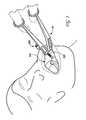
- FIG. 1is a perspective view of one preferred forceps embodiment being used in one preferred application.
- FIG. 2is a top plan view of a prior art pair of forceps.
- FIG. 3is a top plan view of the preferred forceps shown in FIG. 1 .
- FIG. 4is a bottom plan view of the preferred forceps shown in FIG. 1 .
- FIG. 5is a side view of the preferred forceps shown in FIG. 1 .
- FIG. 6is a perspective view of one of the elongated members of the preferred forceps shown in FIG. 1 .
- FIG. 7is a perspective view of the other elongated member of the preferred forceps shown in FIG. 1 .
- FIG. 1an exemplary pair of forceps 10 is shown in FIG. 1 being used in one preferred application—a maxillofacial operation involving inserting self-drilling screws into a human mandible. Forceps 10 is shown inserted into the patient's mouth 100 and around a threaded cannula 200 .
- exemplary forceps 10includes first and second elongated members or arms 20 and 30 pivotally connected together.
- a head 12is defined by respective head portions 21 and 31
- a handle 14is defined by handle portions 22 and 32 .
- Elongated members 20 and 30are connected at a joint 16 .
- joint 16is non-permanent; that is, the forceps are designed and manufactured to be disassembled for packaging, cleaning/sterilization, and assembled for use. Note that permanent joints can be used in alternative embodiments.
- Each of head portions 21 and 31includes a jaw 23 , 33 having an inner surface 24 , 34 .
- the inner jaw surfacescomprise a groove 25 , 35 that collectively define a gripping chamber 18 when jaws 23 and 33 are converged.
- Gripping chamber 18preferably is threaded to facilitate a secure engagement of a cannula or other device. Non-threaded gripping chambers however can equally be employed. Gripping chamber is shown being substantially cylindrical, but it is not limited to this geometry. Outer surfaces of a cannula or any other device may also be threaded (see, for example, threads 210 on cannula 200 shown in FIG. 1 ), such that the threads associated with gripping chamber 18 can engage threads on the device or object being grasped.
- inner jaw surfaces 24 and 34are tapered outwardly in a direction from gripping chamber 18 to respective distal ends 26 , 36 of the jaws to define an engagement guide (“V-entry”).
- Distal ends 26 and 36are preferably rounded, or otherwise blunt, to prevent injury to the medical attendant or patient.
- gripping chamber 18is located at respective proximal ends 27 , 37 of the jaws so that a cannula or other device can be positively engaged by “bottoming out” the jaws around a cannula.
- V-entryand “bottoming out” features are optional, and can be employed to facilitate blind location and engagement of a device, particularly when the device is positioned in an area having a limited field of vision, such as, for example, in a patient's mouth.
- forceps 10can also be used to retract soft tissue. This is shown in FIG. 1 .
- the patient's cheekis retracted or pulled away from its normal resting position to enable a medical attendant to observe what is happening inside the mouth, and to permit placement and manipulation of objects into the mouth.
- At least some of the head and/or the handlegenerally define a tissue contacting surface.
- Soft tissuecan generally be retracted through geometrical and/or dimensional aspects of the tissue contacting surface, by simply moving the forceps after contacting the soft tissue, or through a combination of the two.
- forceps 10have a tissue contacting (retracting) surface 40 that is primarily defined by the outer surface of head portion 21 , and partially defined by exposed portions of an outer surface of head portion 31 . Depending on the length of the forceps' head and the depth of insertion into the mouth (or other area), tissue contacting surface 40 may also be partially defined by adjacent handle portions 22 and 32 . Tissue contacting surface 40 has a width 42 that is preferably between about 5 and 50 mm, more preferably at least about 15 mm, and even more-preferably at least about 20 mm.
- FIG. 5A side view of exemplary forceps 10 is shown in FIG. 5 . From this view, one can see that handle 14 can be angled with respect to head 12 at an angle 44 . Generally, angle 44 is between about 10 degrees and 90 degrees, preferably between about 10 degrees and 45 degrees, and more preferably between about 20 degrees and 30 degrees. In one preferred embodiment, angle 44 is around 25 degrees. Handle 14 may also be parallel with head 12 ; that is, angle 44 would be substantially 0 degrees. In preferred embodiments, and as shown in the figures, handle 14 is angled in a direction towards tissue contact surface 40 . Handle 14 itself can also contain an angle 46 that is preferably on the order of about 10 degrees to about 30 degrees, and more preferably about 20 degrees, although smaller and larger angles are contemplated by the present invention.
- angle 44is between about 10 degrees and 90 degrees, preferably between about 10 degrees and 45 degrees, and more preferably between about 20 degrees and 30 degrees. In one preferred embodiment, angle 44 is around 25 degrees. Handle 14 may also be parallel with head 12 ; that
- Angle 46is defined at the intersection of linear handle sections 47 and 48 .
- An elevation change from head 12 to a distal end of handle 14can be accomplished as shown, through multiple linear sections and corresponding angles (similar or dissimilar in magnitude), through one or more curvilinear sections, through a combination of linear and curvilinear sections, or through other manners known to the skilled artisan.
- handle section 47(of each handle portion) has a rectangular cross-sectional shape and is oriented so as to maximize the width of the respective handle portions, which in turn, may facilitate the tissue retraction function.
- handle section 48(of each handle portion) has a circular cross-sectional area. Other cross-sectional shapes can equally be employed.
- the forceps' handlemay have a homogenous or heterogeneous cross-sectional shape.
- Head portions 21 , 31 and handle portions 22 , 32may optionally comprise cavities 60 formed in various surfaces, including the top and bottom surfaces, as is shown in the figures. Cavities 60 allow preferred forceps embodiments to employ wide tissue contacting surfaces without substantially increasing the metal requirements for their manufacture. If cavities are employed, it should be understood that there are no limitations to the size, geometry, or uniformity of the cavities.
- Elongated members 20 and 30are preferably separable, with our without the use of tools.
- elongated member 20is shown separated from elongated member 30 .
- Elongated member 20has a male joint component 70 extending from a surface of its head portion 21 .
- Male joint component 70includes a post 72 and a flange 74 disposed circumferentially around post 72 , preferably in a non-continuous manner.
- the configuration of post 72 and flange 74may differ from that shown in FIG. 6 .
- Male joint component 70may be integrally formed with elongated member 20 , or may alternately be manufactured separately and then joined to member 20 with any number of techniques.
- Elongated member 30is depicted in FIG. 7 .
- Elongated member 30has a female joint component 80 defined by an aperture 82 and a rib 84 disposed on the aperture's surface, preferably in a non-continuous manner.
- Female joint component 80similarly may be integrally formed with elongated member 30 or separately manufactured.
- Aperture 82may alternately take the form of a recess in head portion 31 .
- Elongated members 20 and 30are simply rotated in an opposite direction and pulled apart for disassembly.
- joints and corresponding joint componentscan be used to effect the preferred separability aspect. And different types of manipulation and steps may be required for assembly and disassembly in comparison to that described above.
- preferred forceps embodimentsmay be used for retracting a patient's cheek and/or performing one or more maxillofacial procedures.
- a method for retracting a patient's cheekcomprising the steps of assembling exemplary elongated members 20 and 30 (preferably without the use of tools) and positioning the assembled forceps into a patient's mouth so that the patient's cheek is retracted from its normal resting position.
- Various maxillofacial proceduressuch as, for example, stabilizing a fractured mandible, can be facilitated via the preferred retracting forceps.
- a cannulais typically inserted through a patient's cheek, during some maxillofacial procedures, to permit the passage of instruments and/or fasteners.
- the forcepscan be inserted through the patient's mouth to securely hold the cannula, while also retracting the patient's cheek. After completing the procedure, the forceps can be disassembled for cleaning and/or sterilization.
- the forcepsare preferably separable so that surfaces are non-contacting during sterilization to help ensure the sterilization is effective. The forceps can then be reassembled and employed for another chosen procedure.
- Forceps in accordance with preferred embodimentscan be made from any bio-inert material, for example, stainless steel or titanium.
- the forcepsmay optionally contain a coating or medicament.
- the forcepsmay be made through any number of manufacturing techniques known to the skilled artisan, including, but not limited to, forging and metal injection molding.
Landscapes
- Health & Medical Sciences (AREA)
- Surgery (AREA)
- Life Sciences & Earth Sciences (AREA)
- Medical Informatics (AREA)
- Animal Behavior & Ethology (AREA)
- Engineering & Computer Science (AREA)
- Biomedical Technology (AREA)
- Heart & Thoracic Surgery (AREA)
- Veterinary Medicine (AREA)
- Molecular Biology (AREA)
- Nuclear Medicine, Radiotherapy & Molecular Imaging (AREA)
- General Health & Medical Sciences (AREA)
- Public Health (AREA)
- Ophthalmology & Optometry (AREA)
- Surgical Instruments (AREA)
- Dental Tools And Instruments Or Auxiliary Dental Instruments (AREA)
- Electrotherapy Devices (AREA)
- Steering Control In Accordance With Driving Conditions (AREA)
- Adornments (AREA)
Abstract
Description
Claims (26)
Priority Applications (15)
| Application Number | Priority Date | Filing Date | Title |
|---|---|---|---|
| US11/105,661US8152834B2 (en) | 2005-04-13 | 2005-04-13 | Forceps and system using same |
| CA2604704ACA2604704C (en) | 2005-04-13 | 2006-04-12 | Forceps and system using same |
| EP06750046AEP1868514B1 (en) | 2005-04-13 | 2006-04-12 | Forceps and system using same |
| DE602006010838TDE602006010838D1 (en) | 2005-04-13 | 2006-04-12 | PLIERS AND SYSTEM FOR THEIR USE |
| CN2006800119692ACN101160100B (en) | 2005-04-13 | 2006-04-12 | Forceps and system using same |
| KR1020077022407AKR101277098B1 (en) | 2005-04-13 | 2006-04-12 | Forceps and system using same |
| JP2008506692AJP5039026B2 (en) | 2005-04-13 | 2006-04-12 | Forceps and system using the same |
| PCT/US2006/013874WO2006113355A1 (en) | 2005-04-13 | 2006-04-12 | Forceps and system using same |
| BRPI0609409-0ABRPI0609409B1 (en) | 2005-04-13 | 2006-04-12 | PAIR OF FORCEPS |
| AU2006236779AAU2006236779A1 (en) | 2005-04-13 | 2006-04-12 | Forceps and system using same |
| ES06750046TES2334828T3 (en) | 2005-04-13 | 2006-04-12 | FORCEPS AND USE SYSTEM. |
| AT06750046TATE450214T1 (en) | 2005-04-13 | 2006-04-12 | PLIERS AND SYSTEM FOR YOUR USE |
| TW095113056ATWI380794B (en) | 2005-04-13 | 2006-04-12 | Forceps and system using same |
| PL06750046TPL1868514T3 (en) | 2005-04-13 | 2006-04-12 | Forceps and system using same |
| ZA200708335AZA200708335B (en) | 2005-04-13 | 2007-09-28 | Forceps and system using same |
Applications Claiming Priority (1)
| Application Number | Priority Date | Filing Date | Title |
|---|---|---|---|
| US11/105,661US8152834B2 (en) | 2005-04-13 | 2005-04-13 | Forceps and system using same |
Publications (2)
| Publication Number | Publication Date |
|---|---|
| US20060235466A1 US20060235466A1 (en) | 2006-10-19 |
| US8152834B2true US8152834B2 (en) | 2012-04-10 |
Family
ID=36716956
Family Applications (1)
| Application Number | Title | Priority Date | Filing Date |
|---|---|---|---|
| US11/105,661Active2026-07-08US8152834B2 (en) | 2005-04-13 | 2005-04-13 | Forceps and system using same |
Country Status (15)
| Country | Link |
|---|---|
| US (1) | US8152834B2 (en) |
| EP (1) | EP1868514B1 (en) |
| JP (1) | JP5039026B2 (en) |
| KR (1) | KR101277098B1 (en) |
| CN (1) | CN101160100B (en) |
| AT (1) | ATE450214T1 (en) |
| AU (1) | AU2006236779A1 (en) |
| BR (1) | BRPI0609409B1 (en) |
| CA (1) | CA2604704C (en) |
| DE (1) | DE602006010838D1 (en) |
| ES (1) | ES2334828T3 (en) |
| PL (1) | PL1868514T3 (en) |
| TW (1) | TWI380794B (en) |
| WO (1) | WO2006113355A1 (en) |
| ZA (1) | ZA200708335B (en) |
Cited By (7)
| Publication number | Priority date | Publication date | Assignee | Title |
|---|---|---|---|---|
| US20110264149A1 (en)* | 2010-04-27 | 2011-10-27 | Dana Pappalardo | Bone fixation system including k-wire compression |
| US20130041370A1 (en)* | 2011-08-09 | 2013-02-14 | Tyco Healthcare Group Lp | Surgical Forceps |
| US20150111171A1 (en)* | 2013-10-21 | 2015-04-23 | Steven Peterson | Coping and crown holder |
| US9113969B2 (en) | 2010-04-27 | 2015-08-25 | DePuy Synthes Products, Inc. | Bone fixation systems and methods of use |
| USD759818S1 (en)* | 2015-04-10 | 2016-06-21 | Steven Peterson | Coping and crown holder |
| US20210393379A1 (en)* | 2020-06-19 | 2021-12-23 | Greggory Joseph DiLauri | Pin engagement device relating to guided placement in a surgical procedure |
| US20220323177A1 (en)* | 2021-04-07 | 2022-10-13 | Sappenfield Christopher C | Dental devices and related methods |
Families Citing this family (21)
| Publication number | Priority date | Publication date | Assignee | Title |
|---|---|---|---|---|
| USD557415S1 (en)* | 2005-11-23 | 2007-12-11 | Karl Storz Gmbh & Co. Kg | Medical instrument |
| FR2946858A1 (en)* | 2009-06-17 | 2010-12-24 | Alternative Medicale | Medical usage instrument e.g. tampon holder, to seize absorbing pad, has snap-on tooth defining arched side face and provided with locking edge, and guiding units for pivotingly guiding branch with respect to another branch |
| BRPI1001125B1 (en)* | 2010-04-29 | 2021-06-15 | Adalberto De Carvalho Vale | ERGONOMIC TOOL FOR ATRAUMATIC EXODONTICS |
| RU2485908C2 (en)* | 2010-12-07 | 2013-06-27 | Компания с ограниченной ответственностью Глобитек 2000 | Method of creating hemostasis with possibility of blood flow recovery in tubular elastic structures of organism and devices for its realisation |
| US20120302852A1 (en)* | 2011-04-25 | 2012-11-29 | Matos Jeffrey A | Implantable medical device removal/insertion tool |
| CN104245233A (en)* | 2012-01-10 | 2014-12-24 | 考尔坦/威登有限公司 | Hand tool joint |
| CN102551816B (en)* | 2012-02-14 | 2014-01-08 | 周剑虹 | Mandibular condyle fracture reduction dilator |
| US9345566B2 (en)* | 2012-09-26 | 2016-05-24 | Cook Medical Technologies Llc | Delivery device and system for open surgical repair |
| US20140107658A1 (en)* | 2012-10-11 | 2014-04-17 | Michael J. Yaremchuk | Surgical Instrument |
| WO2014103095A1 (en)* | 2012-12-27 | 2014-07-03 | ディーブイエックス株式会社 | Forceps |
| US20150112336A1 (en)* | 2013-10-20 | 2015-04-23 | Kogent Surgical, LLC | Bipolar forceps |
| JP5858116B1 (en)* | 2014-09-09 | 2016-02-10 | 株式会社Ydm | Extraction forceps |
| US10376277B2 (en)* | 2016-02-18 | 2019-08-13 | Crea Ip B.V. | Serrated forceps |
| US10772676B2 (en) | 2016-05-31 | 2020-09-15 | Kogent Surgical, LLC | Microsurgical bipolar forceps |
| CN106224692A (en)* | 2016-08-31 | 2016-12-14 | 中船黄埔文冲船舶有限公司 | A kind of orifice sealing device |
| CN106264686A (en)* | 2016-10-25 | 2017-01-04 | 蒲骁麟 | Universal puncture locator |
| CN108420474B (en)* | 2018-03-14 | 2019-02-26 | 山东大学 | Labial-cheek and mucoperiosteal flap simultaneous traction retractor assembly and method of use |
| CN109171912B (en)* | 2018-09-10 | 2021-02-02 | 李占勇 | Throat expansion and foreign matter taking device |
| KR102180976B1 (en)* | 2018-09-14 | 2020-11-19 | 이진균 | Forceps for removing dental implant fixture |
| CN112006766A (en)* | 2020-08-31 | 2020-12-01 | 上海三友医疗器械股份有限公司 | Hook rod connecting assembly and internal fixing system |
| JP2023545391A (en)* | 2020-10-08 | 2023-10-30 | アキュームド・エルエルシー | Devices and systems for bone fixation based on nails |
Citations (83)
| Publication number | Priority date | Publication date | Assignee | Title |
|---|---|---|---|---|
| US254643A (en) | 1882-03-07 | Chaeles h | ||
| US256525A (en) | 1882-04-18 | whiting | ||
| US360695A (en) | 1887-04-05 | Dental regulating device | ||
| US455822A (en) | 1891-07-14 | Sounding-post | ||
| US597582A (en) | 1898-01-18 | Teeth-regulator | ||
| US620853A (en)* | 1899-03-07 | richter | ||
| US827392A (en) | 1903-11-16 | 1906-07-31 | Caspar Prangemeier | Implement for driving in nails. |
| US864558A (en) | 1904-08-18 | 1907-08-27 | Gustav F Richter | Separable pivot-joint. |
| US891061A (en) | 1908-01-20 | 1908-06-16 | Carl Einar Hansen | Tongs. |
| US1001042A (en) | 1910-11-28 | 1911-08-22 | Clyde C Kadel | Sectional nut. |
| US1021110A (en) | 1911-09-18 | 1912-03-26 | John Niewohner | Nut-lock. |
| US1333243A (en) | 1919-03-15 | 1920-03-09 | Wilson S Bowers | Pliers |
| US1973569A (en) | 1933-05-12 | 1934-09-11 | Robert B Kurtz | Surgical instrument |
| DE743853C (en) | 1939-03-11 | 1944-01-04 | Alois Hipp | Detachable joint for surgical instruments or the like. |
| US2375094A (en)* | 1943-09-29 | 1945-05-01 | White S Dental Mfg Co | Orthodontic pliers |
| US2387928A (en) | 1944-01-27 | 1945-10-30 | Monnier Russel | Hand tool |
| US2632661A (en)* | 1948-08-14 | 1953-03-24 | Cristofv Cristjo | Joint for surgical instruments |
| US2641149A (en) | 1951-06-27 | 1953-06-09 | Petersen Mfg | Gripping tool |
| AT192049B (en) | 1956-02-13 | 1957-09-25 | Franz Fischer | Device for regulating tooth position |
| DE1049533B (en) | 1959-01-29 | Udine Ferruccio Bertoni (Italien) | Jaw expansion screw | |
| US2932894A (en)* | 1957-04-03 | 1960-04-19 | Joseph A Sheldon | Dental instrument for ligating, placing, and removing pins, adjusting, etc. |
| US3161085A (en) | 1963-01-25 | 1964-12-15 | James T Pratt | Fuse puller |
| US3202023A (en) | 1963-04-05 | 1965-08-24 | John T Parker | Gutter clamp |
| US3329001A (en) | 1964-07-13 | 1967-07-04 | Acro Die And Stamping Co | Hand tool for adjusting needle eye laps |
| US3454001A (en) | 1965-06-03 | 1969-07-08 | Hugo Stockfisch | Orthopedic treatment apparatus for the jaw bones |
| US3473528A (en) | 1966-04-20 | 1969-10-21 | Sidney Mishkin | Sternal stabilizer |
| US3653284A (en) | 1970-10-27 | 1972-04-04 | George O Pynchon | Plastic pipe gripping tool |
| US4035917A (en)* | 1975-12-23 | 1977-07-19 | James Norman Roberts | Reinforcing dental pin cutter and retainer |
| US4144643A (en) | 1977-01-19 | 1979-03-20 | Krygier Stanley J | Maxillary orthopedic suture separating orthodontic appliance |
| US4179782A (en) | 1978-05-01 | 1979-12-25 | The United States Of America As Represented By The Secretary Of The Navy | Cable terminal-ferrule attaching apparatus |
| US4308863A (en) | 1979-10-18 | 1982-01-05 | Ace Orthopedic Manufacturing, Inc. | External fixation device |
| US4318316A (en) | 1979-10-12 | 1982-03-09 | Guilliams Charles M | Locking pliers for gripping threaded hanger rods |
| US4353273A (en) | 1980-10-30 | 1982-10-12 | Inland Manufacturing Company | Pliers for plastic radiator tank replacement |
| US4361130A (en) | 1980-10-28 | 1982-11-30 | Mark Talaba | Glass sheet shaping and trimming (grozing) tool and method of use |
| US4386603A (en) | 1981-03-23 | 1983-06-07 | Mayfield Jack K | Distraction device for spinal distraction systems |
| US4445513A (en) | 1981-05-29 | 1984-05-01 | Max Bernhard Ulrich | Device for straightening spinal column |
| US4730608A (en) | 1986-03-05 | 1988-03-15 | Schlein Allen P | External bone-anchoring fixator |
| US4848368A (en) | 1988-04-25 | 1989-07-18 | Kronner Richard F | Universal external fixation frame assembly |
| US5023989A (en) | 1989-11-22 | 1991-06-18 | Hargrave David L | Tool for repairing pop-up sprinklers |
| DE4115548A1 (en) | 1990-05-17 | 1991-11-21 | Storz Karl | Surgical forceps for use in laparoscopy - have jaws of half cylinder form held closed by spring |
| USD323214S (en)* | 1989-03-30 | 1992-01-14 | ACE Surgical Supply Co. | Swivel forcep screw driver holder for dental implants |
| US5084935A (en)* | 1990-02-27 | 1992-02-04 | Orbis-Werk Groten Gmbh & Co. Kg | Multiple-purpose wire shaping and cutting tool |
| US5120221A (en)* | 1989-12-29 | 1992-06-09 | Orenstein Jonathan H | Dental clamp for use in implant restorative dentistry |
| US5147358A (en) | 1990-10-23 | 1992-09-15 | Remmler Daniel J | Cranial fixation-distraction and positioning apparatus and method |
| US5197879A (en)* | 1991-09-06 | 1993-03-30 | Fowler Iii Hudson D | Orthodontic, medical, dental tool |
| US5232360A (en)* | 1991-09-16 | 1993-08-03 | Luis Ingels | Orthodontic pliers |
| US5391181A (en) | 1993-10-22 | 1995-02-21 | Zimmer, Inc. | Orthopaedic holding forceps |
| WO1996028110A2 (en) | 1995-03-15 | 1996-09-19 | Bernhard Förster Gmbh | Jackscrew for use in correcting misalignments of teeth |
| WO1996029964A1 (en) | 1995-03-30 | 1996-10-03 | Richard George Palmisano | Apparatus and methods for treatment of conditions including obstructive sleep apnea and snoring |
| US5562447A (en)* | 1993-09-17 | 1996-10-08 | Gc Corporation | Implant fixture, and forceps for implant fixtures |
| US5564920A (en) | 1993-05-06 | 1996-10-15 | Klapper; Lewis | Palatal expander |
| US5575790A (en) | 1995-03-28 | 1996-11-19 | Rensselaer Polytechnic Institute | Shape memory alloy internal linear actuator for use in orthopedic correction |
| US5624454A (en) | 1994-07-31 | 1997-04-29 | Palti; Yoram | Padded vascular clamp |
| WO1998010708A1 (en) | 1996-09-12 | 1998-03-19 | Bernhard Förster Gmbh | Palatal jackscrew |
| US5746757A (en)* | 1996-01-17 | 1998-05-05 | Mcguire; David A. | Suturing jig and method for using same |
| US5769850A (en) | 1996-10-16 | 1998-06-23 | Chin; Martin | Apparatus and method for submergible, self-retaining distraction osteogenesis |
| US5799381A (en) | 1996-01-16 | 1998-09-01 | Gannon; Todd Edward | Stud nail pliers apparatus |
| US5829323A (en) | 1996-08-27 | 1998-11-03 | Liston; Douglas A. | Nail spike guide and support hand tool |
| US5885290A (en) | 1996-12-09 | 1999-03-23 | Guerrero; Cesar A. | Intra-oral bone distraction device |
| US5885283A (en) | 1992-08-04 | 1999-03-23 | Gittleman; Neal B. | Osteogenic mandibular distention apparatus and method |
| US5891161A (en)* | 1997-11-24 | 1999-04-06 | Graser; Robert E. | Wire insertion guide and method of use in pinning bones |
| US5902304A (en) | 1995-12-01 | 1999-05-11 | Walker; David A. | Telescopic bone plate for use in bone lengthening by distraction osteogenesis |
| US5993448A (en) | 1995-10-02 | 1999-11-30 | Remmler; Daniel J. | Implantable apparatus, matrix and method for correction of craniofacial bone deformities |
| US6036692A (en) | 1997-02-12 | 2000-03-14 | Sdgi Holdings, Inc. | Rod introducer forceps |
| US6051004A (en) | 1999-09-20 | 2000-04-18 | Gill; Darrell | Combination needle holder and suture cutter medical instrument |
| US6206882B1 (en) | 1999-03-30 | 2001-03-27 | Surgical Dynamics Inc. | Plating system for the spine |
| US20010004858A1 (en) | 1999-04-13 | 2001-06-28 | Robert E. Kachergius | Fastener extractor |
| US6256855B1 (en) | 1995-12-04 | 2001-07-10 | Richard L. Schall | Hinge pin remover |
| US6267589B1 (en) | 1998-05-13 | 2001-07-31 | Ormco Corporation | Orthodontic screw expansion device |
| US6328745B1 (en) | 1998-11-24 | 2001-12-11 | The Trustees Of Columbia University In The City Of New York | Palate expander |
| JP2001340354A (en) | 2000-03-30 | 2001-12-11 | Kazuko Kawaguchi | Remover for crown restoration or the like |
| US20020031741A1 (en) | 1998-04-23 | 2002-03-14 | Williams Michael O. | Bimaxillary jaw expanding appliance |
| US6361541B1 (en) | 1998-07-17 | 2002-03-26 | The University Of Iowa Research Foundation | Surgical instrument for extracting tissue ingrowth from a permeable member of an implanted catheter |
| US6428544B1 (en)* | 2001-07-16 | 2002-08-06 | Third Millennium Engineering, Llc | Insertion tool for use with trial intervertebral distraction spacers |
| EP0846446B1 (en) | 1996-12-09 | 2003-08-20 | Leone S.p.A. | Orthodontic screw for a fast expansion on the anterior sector of the maxillary arch |
| DE202004002560U1 (en) | 2004-02-19 | 2004-04-22 | Helmut Zepf Medizintechnik Gmbh | Dental forceps |
| US20040093020A1 (en)* | 2000-06-10 | 2004-05-13 | Sinton Richard Thompson | Hand held surgical instrument |
| US20040106947A1 (en) | 2002-03-25 | 2004-06-03 | Tri-State Hospital Supply Corporation | Surgical instrument with snag free box hinge |
| US20040152044A1 (en)* | 2001-04-23 | 2004-08-05 | Russell Khan-Sullman | Dental forceps for tooth extraction |
| US20050004590A1 (en) | 2003-07-01 | 2005-01-06 | Waters Amneris C. | Medical device to remove hubs/ends of intravenous tubing |
| US20050033339A1 (en)* | 1999-09-08 | 2005-02-10 | Jeffrey Grayzel | Percutaneous entry system and method |
| US20050191598A1 (en)* | 2004-03-01 | 2005-09-01 | Robert Anderson | Dental instrument |
| US7588579B2 (en) | 2000-01-11 | 2009-09-15 | Synthes Usa, Llc | Apparatus for intraoral distraction osteotomy to widen the upper jaw |
Family Cites Families (7)
| Publication number | Priority date | Publication date | Assignee | Title |
|---|---|---|---|---|
| USD254643S (en)* | 1978-02-06 | 1980-04-08 | Henry Ashenfarb | Illuminated picture frame |
| USD256525S (en)* | 1978-09-25 | 1980-08-26 | Contempo Metal Furniture Co. of Calif. | Chair |
| US5984864A (en)* | 1997-10-07 | 1999-11-16 | Ethicon Endo-Surgery, Inc. | Tissue stabilization device for use during surgery |
| EP1237490B1 (en)* | 1999-09-08 | 2012-07-04 | Joseph Grayzel | Percutaneous entry system |
| US20030120306A1 (en)* | 2000-04-21 | 2003-06-26 | Vascular Control System | Method and apparatus for the detection and occlusion of blood vessels |
| USD455822S1 (en)* | 2001-04-05 | 2002-04-16 | Kohler Co. | Water closet |
| WO2004105656A1 (en)* | 2003-05-27 | 2004-12-09 | Pentax Corporation | Surgical instrument |
- 2005
- 2005-04-13USUS11/105,661patent/US8152834B2/enactiveActive
- 2006
- 2006-04-12CNCN2006800119692Apatent/CN101160100B/enactiveActive
- 2006-04-12BRBRPI0609409-0Apatent/BRPI0609409B1/enactiveIP Right Grant
- 2006-04-12CACA2604704Apatent/CA2604704C/ennot_activeExpired - Fee Related
- 2006-04-12PLPL06750046Tpatent/PL1868514T3/enunknown
- 2006-04-12ESES06750046Tpatent/ES2334828T3/enactiveActive
- 2006-04-12AUAU2006236779Apatent/AU2006236779A1/ennot_activeAbandoned
- 2006-04-12KRKR1020077022407Apatent/KR101277098B1/ennot_activeExpired - Fee Related
- 2006-04-12EPEP06750046Apatent/EP1868514B1/enactiveActive
- 2006-04-12WOPCT/US2006/013874patent/WO2006113355A1/enactiveApplication Filing
- 2006-04-12ATAT06750046Tpatent/ATE450214T1/enactive
- 2006-04-12TWTW095113056Apatent/TWI380794B/enactive
- 2006-04-12JPJP2008506692Apatent/JP5039026B2/enactiveActive
- 2006-04-12DEDE602006010838Tpatent/DE602006010838D1/enactiveActive
- 2007
- 2007-09-28ZAZA200708335Apatent/ZA200708335B/enunknown
Patent Citations (88)
| Publication number | Priority date | Publication date | Assignee | Title |
|---|---|---|---|---|
| DE1049533B (en) | 1959-01-29 | Udine Ferruccio Bertoni (Italien) | Jaw expansion screw | |
| US256525A (en) | 1882-04-18 | whiting | ||
| US360695A (en) | 1887-04-05 | Dental regulating device | ||
| US455822A (en) | 1891-07-14 | Sounding-post | ||
| US597582A (en) | 1898-01-18 | Teeth-regulator | ||
| US620853A (en)* | 1899-03-07 | richter | ||
| US254643A (en) | 1882-03-07 | Chaeles h | ||
| US827392A (en) | 1903-11-16 | 1906-07-31 | Caspar Prangemeier | Implement for driving in nails. |
| US864558A (en) | 1904-08-18 | 1907-08-27 | Gustav F Richter | Separable pivot-joint. |
| US891061A (en) | 1908-01-20 | 1908-06-16 | Carl Einar Hansen | Tongs. |
| US1001042A (en) | 1910-11-28 | 1911-08-22 | Clyde C Kadel | Sectional nut. |
| US1021110A (en) | 1911-09-18 | 1912-03-26 | John Niewohner | Nut-lock. |
| US1333243A (en) | 1919-03-15 | 1920-03-09 | Wilson S Bowers | Pliers |
| US1973569A (en) | 1933-05-12 | 1934-09-11 | Robert B Kurtz | Surgical instrument |
| DE743853C (en) | 1939-03-11 | 1944-01-04 | Alois Hipp | Detachable joint for surgical instruments or the like. |
| US2375094A (en)* | 1943-09-29 | 1945-05-01 | White S Dental Mfg Co | Orthodontic pliers |
| US2387928A (en) | 1944-01-27 | 1945-10-30 | Monnier Russel | Hand tool |
| US2632661A (en)* | 1948-08-14 | 1953-03-24 | Cristofv Cristjo | Joint for surgical instruments |
| US2641149A (en) | 1951-06-27 | 1953-06-09 | Petersen Mfg | Gripping tool |
| AT192049B (en) | 1956-02-13 | 1957-09-25 | Franz Fischer | Device for regulating tooth position |
| US2932894A (en)* | 1957-04-03 | 1960-04-19 | Joseph A Sheldon | Dental instrument for ligating, placing, and removing pins, adjusting, etc. |
| US3161085A (en) | 1963-01-25 | 1964-12-15 | James T Pratt | Fuse puller |
| US3202023A (en) | 1963-04-05 | 1965-08-24 | John T Parker | Gutter clamp |
| US3329001A (en) | 1964-07-13 | 1967-07-04 | Acro Die And Stamping Co | Hand tool for adjusting needle eye laps |
| US3454001A (en) | 1965-06-03 | 1969-07-08 | Hugo Stockfisch | Orthopedic treatment apparatus for the jaw bones |
| US3473528A (en) | 1966-04-20 | 1969-10-21 | Sidney Mishkin | Sternal stabilizer |
| US3653284A (en) | 1970-10-27 | 1972-04-04 | George O Pynchon | Plastic pipe gripping tool |
| US4035917A (en)* | 1975-12-23 | 1977-07-19 | James Norman Roberts | Reinforcing dental pin cutter and retainer |
| US4144643A (en) | 1977-01-19 | 1979-03-20 | Krygier Stanley J | Maxillary orthopedic suture separating orthodontic appliance |
| US4179782A (en) | 1978-05-01 | 1979-12-25 | The United States Of America As Represented By The Secretary Of The Navy | Cable terminal-ferrule attaching apparatus |
| US4318316A (en) | 1979-10-12 | 1982-03-09 | Guilliams Charles M | Locking pliers for gripping threaded hanger rods |
| US4308863A (en) | 1979-10-18 | 1982-01-05 | Ace Orthopedic Manufacturing, Inc. | External fixation device |
| US4361130A (en) | 1980-10-28 | 1982-11-30 | Mark Talaba | Glass sheet shaping and trimming (grozing) tool and method of use |
| US4353273A (en) | 1980-10-30 | 1982-10-12 | Inland Manufacturing Company | Pliers for plastic radiator tank replacement |
| US4386603A (en) | 1981-03-23 | 1983-06-07 | Mayfield Jack K | Distraction device for spinal distraction systems |
| US4445513A (en) | 1981-05-29 | 1984-05-01 | Max Bernhard Ulrich | Device for straightening spinal column |
| US4730608A (en) | 1986-03-05 | 1988-03-15 | Schlein Allen P | External bone-anchoring fixator |
| US4848368A (en) | 1988-04-25 | 1989-07-18 | Kronner Richard F | Universal external fixation frame assembly |
| USD323214S (en)* | 1989-03-30 | 1992-01-14 | ACE Surgical Supply Co. | Swivel forcep screw driver holder for dental implants |
| US5023989A (en) | 1989-11-22 | 1991-06-18 | Hargrave David L | Tool for repairing pop-up sprinklers |
| US5120221A (en)* | 1989-12-29 | 1992-06-09 | Orenstein Jonathan H | Dental clamp for use in implant restorative dentistry |
| US5084935A (en)* | 1990-02-27 | 1992-02-04 | Orbis-Werk Groten Gmbh & Co. Kg | Multiple-purpose wire shaping and cutting tool |
| DE4115548A1 (en) | 1990-05-17 | 1991-11-21 | Storz Karl | Surgical forceps for use in laparoscopy - have jaws of half cylinder form held closed by spring |
| US5147358A (en) | 1990-10-23 | 1992-09-15 | Remmler Daniel J | Cranial fixation-distraction and positioning apparatus and method |
| US5197879A (en)* | 1991-09-06 | 1993-03-30 | Fowler Iii Hudson D | Orthodontic, medical, dental tool |
| US5232360A (en)* | 1991-09-16 | 1993-08-03 | Luis Ingels | Orthodontic pliers |
| US5885283A (en) | 1992-08-04 | 1999-03-23 | Gittleman; Neal B. | Osteogenic mandibular distention apparatus and method |
| EP0706349B1 (en) | 1993-05-06 | 1999-08-25 | KLAPPER, Lewis | Palatal expander |
| US5564920A (en) | 1993-05-06 | 1996-10-15 | Klapper; Lewis | Palatal expander |
| US5562447A (en)* | 1993-09-17 | 1996-10-08 | Gc Corporation | Implant fixture, and forceps for implant fixtures |
| US5391181A (en) | 1993-10-22 | 1995-02-21 | Zimmer, Inc. | Orthopaedic holding forceps |
| US5624454A (en) | 1994-07-31 | 1997-04-29 | Palti; Yoram | Padded vascular clamp |
| WO1996028110A2 (en) | 1995-03-15 | 1996-09-19 | Bernhard Förster Gmbh | Jackscrew for use in correcting misalignments of teeth |
| US5575790A (en) | 1995-03-28 | 1996-11-19 | Rensselaer Polytechnic Institute | Shape memory alloy internal linear actuator for use in orthopedic correction |
| WO1996029964A1 (en) | 1995-03-30 | 1996-10-03 | Richard George Palmisano | Apparatus and methods for treatment of conditions including obstructive sleep apnea and snoring |
| US5993448A (en) | 1995-10-02 | 1999-11-30 | Remmler; Daniel J. | Implantable apparatus, matrix and method for correction of craniofacial bone deformities |
| US5902304A (en) | 1995-12-01 | 1999-05-11 | Walker; David A. | Telescopic bone plate for use in bone lengthening by distraction osteogenesis |
| US6256855B1 (en) | 1995-12-04 | 2001-07-10 | Richard L. Schall | Hinge pin remover |
| US5799381A (en) | 1996-01-16 | 1998-09-01 | Gannon; Todd Edward | Stud nail pliers apparatus |
| US5746757A (en)* | 1996-01-17 | 1998-05-05 | Mcguire; David A. | Suturing jig and method for using same |
| US5829323A (en) | 1996-08-27 | 1998-11-03 | Liston; Douglas A. | Nail spike guide and support hand tool |
| WO1998010708A1 (en) | 1996-09-12 | 1998-03-19 | Bernhard Förster Gmbh | Palatal jackscrew |
| US5769850A (en) | 1996-10-16 | 1998-06-23 | Chin; Martin | Apparatus and method for submergible, self-retaining distraction osteogenesis |
| US5885290A (en) | 1996-12-09 | 1999-03-23 | Guerrero; Cesar A. | Intra-oral bone distraction device |
| EP0846446B1 (en) | 1996-12-09 | 2003-08-20 | Leone S.p.A. | Orthodontic screw for a fast expansion on the anterior sector of the maxillary arch |
| US6036692A (en) | 1997-02-12 | 2000-03-14 | Sdgi Holdings, Inc. | Rod introducer forceps |
| US5891161A (en)* | 1997-11-24 | 1999-04-06 | Graser; Robert E. | Wire insertion guide and method of use in pinning bones |
| US20020031741A1 (en) | 1998-04-23 | 2002-03-14 | Williams Michael O. | Bimaxillary jaw expanding appliance |
| US6267589B1 (en) | 1998-05-13 | 2001-07-31 | Ormco Corporation | Orthodontic screw expansion device |
| US6361541B1 (en) | 1998-07-17 | 2002-03-26 | The University Of Iowa Research Foundation | Surgical instrument for extracting tissue ingrowth from a permeable member of an implanted catheter |
| US6328745B1 (en) | 1998-11-24 | 2001-12-11 | The Trustees Of Columbia University In The City Of New York | Palate expander |
| US6206882B1 (en) | 1999-03-30 | 2001-03-27 | Surgical Dynamics Inc. | Plating system for the spine |
| US20010004858A1 (en) | 1999-04-13 | 2001-06-28 | Robert E. Kachergius | Fastener extractor |
| US20050033339A1 (en)* | 1999-09-08 | 2005-02-10 | Jeffrey Grayzel | Percutaneous entry system and method |
| US6051004A (en) | 1999-09-20 | 2000-04-18 | Gill; Darrell | Combination needle holder and suture cutter medical instrument |
| US7588579B2 (en) | 2000-01-11 | 2009-09-15 | Synthes Usa, Llc | Apparatus for intraoral distraction osteotomy to widen the upper jaw |
| JP2001340354A (en) | 2000-03-30 | 2001-12-11 | Kazuko Kawaguchi | Remover for crown restoration or the like |
| US6413088B1 (en) | 2000-03-30 | 2002-07-02 | Kazuko Kawaguchi | Instrument and method for removing dental restoration |
| US20040093020A1 (en)* | 2000-06-10 | 2004-05-13 | Sinton Richard Thompson | Hand held surgical instrument |
| US20040152044A1 (en)* | 2001-04-23 | 2004-08-05 | Russell Khan-Sullman | Dental forceps for tooth extraction |
| US6428544B1 (en)* | 2001-07-16 | 2002-08-06 | Third Millennium Engineering, Llc | Insertion tool for use with trial intervertebral distraction spacers |
| US20040106947A1 (en) | 2002-03-25 | 2004-06-03 | Tri-State Hospital Supply Corporation | Surgical instrument with snag free box hinge |
| US20050004590A1 (en) | 2003-07-01 | 2005-01-06 | Waters Amneris C. | Medical device to remove hubs/ends of intravenous tubing |
| US20050186536A1 (en)* | 2004-02-19 | 2005-08-25 | Helmut Zepf | Dental pliers |
| US7318725B2 (en)* | 2004-02-19 | 2008-01-15 | Helmut Zepf Medizintechnik Gmbh | Dental pliers |
| DE202004002560U1 (en) | 2004-02-19 | 2004-04-22 | Helmut Zepf Medizintechnik Gmbh | Dental forceps |
| US20050191598A1 (en)* | 2004-03-01 | 2005-09-01 | Robert Anderson | Dental instrument |
| US7165970B2 (en)* | 2004-03-01 | 2007-01-23 | Garrison Dental Solutions, Inc. | Dental instrument |
Non-Patent Citations (5)
| Title |
|---|
| "Malleable". Merriam-Webster Dictionary [online], [retrieved on Nov. 9, 2006], Retrieved from the internet <URL: www.m-w.com. |
| "Thread". Merriam-Webster Dictionary [online], [retrieved on Nov. 9, 2006], Retrieved from the internet <URL: www.m-w.com . |
| English Abstract of WO 96/28110 dated Sep. 19, 1996. |
| English Abstract of WO 98/10708 dated Mar. 19, 1998. |
| Mommaerts, M.Y., "Transpalatal distraction as a method of maxillary expansion," British Journal of Oral and Maxillofacial Surgery, 1999, 37, pp. 268-272. |
Cited By (13)
| Publication number | Priority date | Publication date | Assignee | Title |
|---|---|---|---|---|
| US8936615B2 (en)* | 2010-04-27 | 2015-01-20 | DePuy Synthes Products, LLC | Bone fixation system including K-wire compression |
| US9113969B2 (en) | 2010-04-27 | 2015-08-25 | DePuy Synthes Products, Inc. | Bone fixation systems and methods of use |
| US20110264149A1 (en)* | 2010-04-27 | 2011-10-27 | Dana Pappalardo | Bone fixation system including k-wire compression |
| US9597130B2 (en) | 2010-04-27 | 2017-03-21 | DePuy Synthes Products, Inc. | Bone fixation system including K-wire compression |
| US9770253B2 (en) | 2011-08-09 | 2017-09-26 | Covidien Lp | Surgical forceps |
| US20130041370A1 (en)* | 2011-08-09 | 2013-02-14 | Tyco Healthcare Group Lp | Surgical Forceps |
| US8968306B2 (en)* | 2011-08-09 | 2015-03-03 | Covidien Lp | Surgical forceps |
| US20150111171A1 (en)* | 2013-10-21 | 2015-04-23 | Steven Peterson | Coping and crown holder |
| USD759818S1 (en)* | 2015-04-10 | 2016-06-21 | Steven Peterson | Coping and crown holder |
| US20210393379A1 (en)* | 2020-06-19 | 2021-12-23 | Greggory Joseph DiLauri | Pin engagement device relating to guided placement in a surgical procedure |
| US11766316B2 (en)* | 2020-06-19 | 2023-09-26 | Greggory Joseph DiLauri | Pin engagement device relating to guided placement in a surgical procedure |
| US20220323177A1 (en)* | 2021-04-07 | 2022-10-13 | Sappenfield Christopher C | Dental devices and related methods |
| US12144698B2 (en)* | 2021-04-07 | 2024-11-19 | Sappenfield Christopher C | Dental devices and related methods |
Also Published As
| Publication number | Publication date |
|---|---|
| EP1868514B1 (en) | 2009-12-02 |
| CA2604704C (en) | 2014-10-21 |
| CN101160100B (en) | 2013-03-06 |
| TWI380794B (en) | 2013-01-01 |
| BRPI0609409A2 (en) | 2010-04-06 |
| US20060235466A1 (en) | 2006-10-19 |
| AU2006236779A1 (en) | 2006-10-26 |
| ES2334828T3 (en) | 2010-03-16 |
| JP5039026B2 (en) | 2012-10-03 |
| TW200716051A (en) | 2007-05-01 |
| KR20080009066A (en) | 2008-01-24 |
| KR101277098B1 (en) | 2013-06-20 |
| BRPI0609409B1 (en) | 2023-01-24 |
| ATE450214T1 (en) | 2009-12-15 |
| ZA200708335B (en) | 2008-11-26 |
| WO2006113355A1 (en) | 2006-10-26 |
| DE602006010838D1 (en) | 2010-01-14 |
| EP1868514A1 (en) | 2007-12-26 |
| PL1868514T3 (en) | 2010-04-30 |
| JP2008536568A (en) | 2008-09-11 |
| CN101160100A (en) | 2008-04-09 |
| CA2604704A1 (en) | 2006-10-26 |
Similar Documents
| Publication | Publication Date | Title |
|---|---|---|
| CA2604704C (en) | Forceps and system using same | |
| JP4990546B2 (en) | Angled connection structure for the bullet tip to the bullet shank | |
| US8403840B2 (en) | Medical instrument for creating an access for a minimally invasive intervention | |
| US9603641B2 (en) | Device for osteosynthesis | |
| AU2008212049B2 (en) | Bladeless obturator for use in a surgical trocar assembly | |
| EP0972493B1 (en) | Ultrasonic trocar | |
| JP6847096B2 (en) | Bone fixation implant system | |
| CN108272500A (en) | Self-retaining head of screw | |
| EP2967561A1 (en) | Extended curved tip for surgical apparatus | |
| WO2003096879A3 (en) | Cone tip obturator | |
| US11141163B2 (en) | Circular stapling device with anvil rotation locking structure | |
| JP5937768B2 (en) | Osteosynthesis | |
| US20140128890A1 (en) | Medical device and related methods of use | |
| JP2016152861A (en) | Treatment tool for femur fracture | |
| US9320422B1 (en) | Surgical retractor | |
| AU2019284089A1 (en) | Access assembly including flexible cannula | |
| US20120310049A1 (en) | Medical Access Device Having A Protection Against An Excessive Application Of Leverage | |
| EP2674115B1 (en) | System for forming a t-shaped surgical clip | |
| CN110709020A (en) | Tunnel device | |
| US20250152181A1 (en) | Revision goal post osteotome | |
| KR101856881B1 (en) | Surgical kelly forceps | |
| BR112020008780B1 (en) | BONE CAGE | |
| AU2012203021A1 (en) | Screw extraction and insertion device | |
| TW201420073A (en) | Detachable reduction and compression bone screw |
Legal Events
| Date | Code | Title | Description |
|---|---|---|---|
| AS | Assignment | Owner name:SYNTHES (USA), PENNSYLVANIA Free format text:ASSIGNMENT OF ASSIGNORS INTEREST;ASSIGNORS:GRIFFITHS, MR. BRYAN;MCGARITY, MR. OWEN CARLOS;REEL/FRAME:016493/0858 Effective date:20050705 | |
| AS | Assignment | Owner name:SYNTHES (USA), PENNSYLVANIA Free format text:CORRECTIVE ASSIGNMENT TO CORRECT THE ASSIGNEE STREET ADDRESS AND CORPORATION INFORMATION IN PARA 2, LINES 1&2 PREVIOUSLY RECORDED ON REEL 016493 FRAME 0858;ASSIGNORS:GRIFFITHS, BRYAN;MCGARITY, OWEN CARLOS;REEL/FRAME:018223/0718;SIGNING DATES FROM 20060411 TO 20060419 Owner name:SYNTHES (USA), PENNSYLVANIA Free format text:CORRECTIVE ASSIGNMENT TO CORRECT THE ASSIGNEE STREET ADDRESS AND CORPORATION INFORMATION IN PARA 2, LINES 1&2 PREVIOUSLY RECORDED ON REEL 016493 FRAME 0858. ASSIGNOR(S) HEREBY CONFIRMS THE ADDRESS IS 1302 WRIGHTS LANE EAST AND SYNTHES (USA)IS A PARTNERSHIP ORGANIZED UNDER THE LAWS OF THE COMMONWEALTH OF PENNSYLVANIA;ASSIGNORS:GRIFFITHS, BRYAN;MCGARITY, OWEN CARLOS;SIGNING DATES FROM 20060411 TO 20060419;REEL/FRAME:018223/0718 | |
| AS | Assignment | Owner name:HFSC COMPANY, PENNSYLVANIA Free format text:ASSIGNMENT OF ASSIGNORS INTEREST;ASSIGNOR:SYNTHES (USA);REEL/FRAME:018393/0668 Effective date:20060424 | |
| AS | Assignment | Owner name:SYNTHES (USA), PENNSYLVANIA Free format text:ASSIGNMENT OF ASSIGNORS INTEREST;ASSIGNOR:HFSC COMPANY;REEL/FRAME:018404/0449 Effective date:20061017 | |
| AS | Assignment | Owner name:SYNTHES GMBH, SWITZERLAND Free format text:ASSIGNMENT OF ASSIGNORS INTEREST;ASSIGNOR:HFSC COMPANY;REEL/FRAME:018894/0439 Effective date:20070213 | |
| AS | Assignment | Owner name:SYNTHES USA, LLC, PENNSYLVANIA Free format text:CHANGE OF NAME;ASSIGNOR:SYNTHES (U.S.A.);REEL/FRAME:022214/0552 Effective date:20081223 Owner name:SYNTHES USA, LLC,PENNSYLVANIA Free format text:CHANGE OF NAME;ASSIGNOR:SYNTHES (U.S.A.);REEL/FRAME:022214/0552 Effective date:20081223 | |
| FEPP | Fee payment procedure | Free format text:PAYOR NUMBER ASSIGNED (ORIGINAL EVENT CODE: ASPN); ENTITY STATUS OF PATENT OWNER: LARGE ENTITY | |
| STCF | Information on status: patent grant | Free format text:PATENTED CASE | |
| FPAY | Fee payment | Year of fee payment:4 | |
| MAFP | Maintenance fee payment | Free format text:PAYMENT OF MAINTENANCE FEE, 8TH YEAR, LARGE ENTITY (ORIGINAL EVENT CODE: M1552); ENTITY STATUS OF PATENT OWNER: LARGE ENTITY Year of fee payment:8 | |
| MAFP | Maintenance fee payment | Free format text:PAYMENT OF MAINTENANCE FEE, 12TH YEAR, LARGE ENTITY (ORIGINAL EVENT CODE: M1553); ENTITY STATUS OF PATENT OWNER: LARGE ENTITY Year of fee payment:12 |