US8152724B2 - Ultrasound guided probe device and method of using same - Google Patents
Ultrasound guided probe device and method of using sameDownload PDFInfo
- Publication number
- US8152724B2 US8152724B2US11/787,290US78729007AUS8152724B2US 8152724 B2US8152724 B2US 8152724B2US 78729007 AUS78729007 AUS 78729007AUS 8152724 B2US8152724 B2US 8152724B2
- Authority
- US
- United States
- Prior art keywords
- probe
- ultrasound transducer
- transducer housing
- probe guide
- guide
- Prior art date
- Legal status (The legal status is an assumption and is not a legal conclusion. Google has not performed a legal analysis and makes no representation as to the accuracy of the status listed.)
- Expired - Fee Related, expires
Links
Images


Classifications
- A—HUMAN NECESSITIES
- A61—MEDICAL OR VETERINARY SCIENCE; HYGIENE
- A61B—DIAGNOSIS; SURGERY; IDENTIFICATION
- A61B8/00—Diagnosis using ultrasonic, sonic or infrasonic waves
- A61B8/44—Constructional features of the ultrasonic, sonic or infrasonic diagnostic device
- A61B8/4444—Constructional features of the ultrasonic, sonic or infrasonic diagnostic device related to the probe
- A—HUMAN NECESSITIES
- A61—MEDICAL OR VETERINARY SCIENCE; HYGIENE
- A61B—DIAGNOSIS; SURGERY; IDENTIFICATION
- A61B8/00—Diagnosis using ultrasonic, sonic or infrasonic waves
- A61B8/08—Clinical applications
- A61B8/0833—Clinical applications involving detecting or locating foreign bodies or organic structures
- A—HUMAN NECESSITIES
- A61—MEDICAL OR VETERINARY SCIENCE; HYGIENE
- A61B—DIAGNOSIS; SURGERY; IDENTIFICATION
- A61B17/00—Surgical instruments, devices or methods
- A61B17/34—Trocars; Puncturing needles
- A61B17/3403—Needle locating or guiding means
- A—HUMAN NECESSITIES
- A61—MEDICAL OR VETERINARY SCIENCE; HYGIENE
- A61B—DIAGNOSIS; SURGERY; IDENTIFICATION
- A61B8/00—Diagnosis using ultrasonic, sonic or infrasonic waves
- A61B8/13—Tomography
- A61B8/14—Echo-tomography
- A—HUMAN NECESSITIES
- A61—MEDICAL OR VETERINARY SCIENCE; HYGIENE
- A61B—DIAGNOSIS; SURGERY; IDENTIFICATION
- A61B17/00—Surgical instruments, devices or methods
- A61B17/34—Trocars; Puncturing needles
- A61B17/3403—Needle locating or guiding means
- A61B2017/3413—Needle locating or guiding means guided by ultrasound
- A—HUMAN NECESSITIES
- A61—MEDICAL OR VETERINARY SCIENCE; HYGIENE
- A61B—DIAGNOSIS; SURGERY; IDENTIFICATION
- A61B8/00—Diagnosis using ultrasonic, sonic or infrasonic waves
- A61B8/08—Clinical applications
- A61B8/0833—Clinical applications involving detecting or locating foreign bodies or organic structures
- A61B8/0841—Clinical applications involving detecting or locating foreign bodies or organic structures for locating instruments
- A—HUMAN NECESSITIES
- A61—MEDICAL OR VETERINARY SCIENCE; HYGIENE
- A61B—DIAGNOSIS; SURGERY; IDENTIFICATION
- A61B90/00—Instruments, implements or accessories specially adapted for surgery or diagnosis and not covered by any of the groups A61B1/00 - A61B50/00, e.g. for luxation treatment or for protecting wound edges
- A61B90/40—Apparatus fixed or close to patients specially adapted for providing an aseptic surgical environment
Definitions
- Medical probe devicesare utilized for many purposes, chief of which include catheterization, centesis, and biopsy procedures. Percutaneous placement of probes using these devices is often performed with techniques which rely on palpable or visible structures. This is neither a simple nor a risk-free procedure. For instance, proper insertion and placement of a percutaneous probe depends on correct localization of anatomical landmarks, proper positioning of the patient in relation to the care provider, and awareness of both the target's depth and angle from the point of probe insertion. Risks of unsuccessful placement of a probe can range from minor complications, such as patient anxiety and discomfort due to repetition of the procedure following incorrect initial placement, to severe complications, such as pneumothorax, arterial or venous laceration, or delay of delivery of life-saving fluids or medications in an emergency situation.
- Ultrasound guided techniques and deviceshave been developed to aid in correct placement of percutaneous probes.
- Ultrasound guided techniquesusually require two people, an ultrasound operator who locates the internal target and keeps an image of the target centrally located on a monitor, and a care provider who attempts to guide the probe to the target based upon the sonogram.
- Such techniquesare very difficult perceptually. For instance, these techniques are complicated by the fact that the person targeting the tissue with the probe is not the same person as is operating the ultrasound.
- the generally thin, cylindrical probeis usually small and reflects very little of the ultrasound beam.
- the small amount of ultrasonic energy that is reflected from the probewill reflect at an angle to the incident beam, resulting in little if any of the reflected energy being detected by the ultrasound transducer.
- the probe itselfis difficult to visualize in the sonogram and the person placing the probe must attempt to guide the probe to the correct location using minimal visual feedback provided by the ultrasound operator physically rocking the ultrasound transducer.
- Rocking the transducerallows the observer to see a series of planar sonograms of the internal region, and, with training, the observer can learn to recognize subtle changes in the sonograms as the probe deflects and penetrates the surrounding tissue and pick up subtle ultrasonic shadow artifacts deep to the probe created when the probe blocks the transmission of the ultrasound beam to the tissue below.
- probe guidewhich can be attached to an ultrasound transducer housing.
- the probe guideis to one side of the ultrasound transducer housing in these devices, and the probe is often inserted at a fixed angle to the plane of the ultrasound beam displayed on the sonogram, restricting the intersection of the ultrasonographic beam and the point of the probe to a very small area in space.
- ultrasonic energyis reflected from the probe back to the transducer.
- the probepasses through the ultrasound beam at a fixed depth range depending on the set angle of the probe guide, and this may not correspond to the depth of the target, in which case it may not be possible to show the juncture of the target and the probe tip on the sonogram at all.
- Another problem that exists when attempting to place a percutaneous probeconcerns movement of the probe following correct placement. For instance, after successfully placing a probe, in many procedures it is desirable for the probe tip to remain at the target location for a period of time, for instance as a catheter wire is inserted or a biopsy taken. Often, a small movement of the hand holding the probe in place can cause the probe tip to shift away from the target, leading to complications. Thus, what is needed in the art is a device and method that can clamp a probe following placement in order to limit motion of the probe tip within the body.
- the term “probe”is herein defined to be device that can be guided by and used in conjunction with the ultrasound devices of the present invention.
- the term “probe”can refer to a needle, a tube, a biopsy device, or any other item that can be guided by the devices as herein described.
- probe deviceis herein defined to be a device that can be utilized with a probe, but does not necessarily include the probe itself.
- the present inventionis directed to a probe device that can include an ultrasound transducer housing which can include an ultrasound transducer for transmitting an ultrasonic beam.
- the ultrasound transducer housingcan define a probe guide opening through the base of the housing.
- the probe guide openingcan pass through the area defined by the ultrasound transducer or outside of this area, depending upon the desired characteristics of the system.
- the devicecan, in one embodiment, also include a sterile seal that can be removably attached to the ultrasound transducer housing.
- the sterile sealcan include, for example, a sterile probe guide that can be removably received within the probe guide opening.
- the sterile sealcan also include a seal base, onto which the base of the ultrasound transducer housing can fit.
- the sterile sealcan include a sterile sleeve, which can be adapted for substantially covering the exterior of the ultrasound transducer housing without blocking movement of a probe through the probe guide.
- the sterile sleevecan include a pliant, disposable material such as a nonwoven web material or a thermoplastic material.
- the medical probe devicecan be a linear, noninvasive probe device incorporating a linear ultrasound array such as is generally known in the art for visualizing vascular targets.
- the probe guide opening defined by the transducer housingcan be perpendicular to the flat base of the linear array device.
- the medical probe devicecan be a convex device, in which the array of elements forming the ultrasound transducer defines an arcuate profile.
- the base of the devicecan also define an arcuate profile that can correspond to the curvature of the ultrasound transducer within the transducer housing.
- the probe guide openingcan be perpendicular to the tangent of the base taken at the point where the probe guide opening passes out of the housing at the base.
- the medical probe device of the present inventioncan include a clamp.
- the clampcan be a mechanical clamp in communication with the ultrasound transducer housing for clamping a probe in the probe guide.
- the medical probe devicecan include a detector, such as a motion detector, in communication with a processing unit.
- the detectorcan detect motion of a probe as it is guided through the probe guide and communicate that information via a data stream to the processing unit.
- the processing unitcan also be in contact with the ultrasound transducer and can be utilized to form the sonogram.
- the processing unitcan use the information in the data stream to display information on a monitor relating the location of the probe in relation to the target.
- the data streamcan be utilized to form a real time virtual image of the probe as it moves through the field and display an image of the probe on the sonogram.
- the path of the probecan define a line that is parallel to the plane displayed on the sonogram.
- information concerning the probe pathcan be displayed on the monitor.
- a targeting line showing the path the probe will takewhich is parallel to the plane of the sonogram, can be displayed on the monitor.
- the present inventionis directed to a sterile seal that may be utilized in conjunction with an ultrasound device.
- the sterile sealcan include a sterile probe guide for use with an ultrasound device in order to provide a sterile barrier between the ultrasound transducer housing and a probe guided through the housing.
- the sterile probe guidecan, in one embodiment, include separable top and bottom portions which can be attached together when the seal is received within the probe guide opening that is defined by the ultrasound transducer housing.
- the sterile sealcan include a sterile sleeve continuous from the sterile probe guide that can substantially enclose the ultrasound transducer housing without blocking motion of a probe through the sterile probe guide.
- the sterile sleevecan comprise a pliant material that can wrap the ultrasound transducer housing and/or the sleeve can comprise a non-pliable base that can cover one or more surfaces of the transducer housing.
- a clamp for clamping a probe in the sterile probe guidecan be integral to the sterile seal.
- the presently disclosed devicesmay be utilized in a variety of medical procedures.
- the devicesmay be utilized to target blood vessels, tissue masses, or fluid-filled cavities.
- the devicesmay be utilized during central venous catheterization procedures.
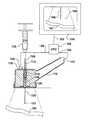
- FIG. 1illustrates one embodiment of an ultrasound transducer housing of the present invention
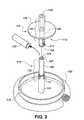
- FIG. 2illustrates one embodiment of a sterile seal according to the present invention including separable top and bottom portions
- FIG. 3illustrates one embodiment of a device of the present invention including an ultrasound transducer housing enclosed by a sterile seal so as to form a sterile probe guide within the probe guide opening that is defined by the ultrasound transducer housing;
- FIG. 4illustrates an isometric view of one embodiment of the top of a sterile seal probe guide according to the present invention including an integral clamp;
- FIG. 5shows a cut-away plan view of the probe guide of FIG. 4 taken along line V-V.
- FIG. 6illustrates a clamping lever suitable for use with the probe guide of FIG. 4 ;
- FIG. 7shows a plan view of the clamping lever of FIG. 6 taken along line VII-VII;
- FIGS. 8A and 8Bare cut-away plan views of a probe held by the clamp of FIGS. 4-7 in both an unclamped position ( FIG. 8A ) and a clamped position ( FIG. 8B );
- FIG. 9illustrates another embodiment of the present invention in which an image of a virtual probe may be correlated with a sonogram
- FIGS. 10A-10Fare planar views of embodiments of ultrasound transducers of the present invention, showing a variety of relationships between the ultrasound transducer and a probe guide opening defined by the transducer housing;
- FIG. 11illustrates another embodiment of the ultrasound transducer housing of the present invention including a convex ultrasound transducer.
- the ultrasound devices of the present inventioninclude an ultrasound transducer housing having an opening therethrough configured to accommodate a probe.
- the openingcan serve as a probe guide.
- the openingcan be configured to accommodate a removable probe guide for the probe.
- the path of a probe guided through the device and hence the location of the probe tipcan be more clearly known in relation to a target imaged by the ultrasound device.
- the presently disclosed devicescan be utilized by a single operator who can control both the ultrasound transducer and the probe during the procedure.
- a probe tipcan be guided to a percutaneous target on a line that is parallel to the plane imaged on the sonogram. That is, either within the plane imaged on the sonogram or adjacent to it, but in either case parallel to it.
- the path of the probe to the targetcan be known, even if it cannot be discerned on the sonogram: the probe will advance toward the target on a straight line and at a predetermined angular relationship to the ultrasound housing base from the probe guide opening that is defined by the transducer housing, past the exit of the probe guide opening, and, while traveling parallel to a plane that can be imaged on a sonogram, to the target that is imaged by the ultrasound.
- the path of the probe and the sonogram imagecan both be defined by the orientation of the transducer and can be coordinated on the target.
- the probeIn order to strike the target, the probe can be merely guided along this known path the desired distance.
- the path of the probecan be perpendicular to the base of the ultrasound transducer housing at the probe guide opening exit.
- the targeting processcan be even further improved by the creation of an image of the known path of travel of the probe or an image of the advancing probe itself, a ‘virtual probe’, either of which can overlay the sonogram formed by the ultrasound device.
- a motion detectorcan register motion of a probe in the probe guide, and that information can be displayed, for instance, as a real time image of the probe on a screen or monitor.
- the location of the probe tip in relation to the target and the moment when the probe tip strikes the targetcan be seen in real time by an operator watching the virtual probe on the monitor during the procedure.
- the presently disclosed inventionis directed to a sterile seal which can cover surfaces of an ultrasound transducer housing that may be near the patient and/or the probe.
- the sterile seal of the present inventioncan include a sterile probe guide.
- the sterile probe guidecan be located within the probe guide opening that passes through the ultrasound transducer housing.
- the probecan pass through the sterile probe guide and not come into contact with the ultrasound transducer housing.
- the presence of a sterile barrier between the ultrasound transducer housing and the probe during the procedurecan greatly enhance patient safety by prevention of infection.
- the sterile sealcan include a sleeve to substantially cover the ultrasound transducer housing.
- the ultrasound transducer housing and related equipmentneed not be sterilized after a procedure, and can be ready to be used again with a new sterile seal after a simple cleansing procedure. As such, a single ultrasound transducer may be used more frequently, making the devices much more economical.
- a removable probe guideis not a requirement of the present devices, however.
- the probe guidemay be the probe guide opening.
- the presently disclosed devicescan be utilized to guide a probe on a known path of travel from the housing itself directly toward a target.
- the sterile seal of the present inventionwhile particularly well suited for use with the ultrasound devices as herein disclosed, can also be utilized with other ultrasound transducers in which a probe guide opening is defined by the ultrasound transducer housing.
- a cannulated needle attached to a syringeis first guided into a vein. After the needle tip is in the lumen of the vein, the needle is held while the syringe is removed from the needle and a guide wire is fed down through the needle and into the vein. During this process, only a slight movement of the needle can cause the needle tip to move out of the vein, and the entire procedure must be repeated.
- one embodiment of the present deviceincludes a clamp for the probe.
- the devicecan include a clamp which can firmly hold the probe in relation to the ultrasound transducer housing and prevent motion of the probe during subsequent procedures such as catheter insertion, biopsy procedures, fluid or gas aspiration, or the like.
- the ultrasound transducer housingcan be much easier to hold in place during such procedures as compared to holding only the small probe, motion of the probe tip can be much less likely when the probe is securely clamped in relation to the ultrasound transducer housing and the transducer housing is held in the hand and further stabilized by patient contact as compared to when only the probe by itself is held in the hand
- FIG. 1illustrates one embodiment of an ultrasound transducer housing generally 100 according to the present invention.
- the transducer housingincludes an ultrasound transducer generally 120 that transmits and receives ultrasonic waves.
- the ultrasound transducer 120can be any type of ultrasound transducer as is generally known in the art.
- the ultrasound transducercan be a piezoelectric transducer formed of one or more piezoelectric crystalline materials arranged in a two or three-dimensional array. Such materials include ferroelectric piezoceramic crystalline materials such as lead zirconate titanate (PZT).
- PZTlead zirconate titanate
- the elements that form the arraycan be individual electrode or electrode segments mounted on a single piezoelectric substrate, such as those described in U.S. Pat. No. 5,291,090 to Dias, which is incorporated herein by reference thereto.
- the ultrasound transducer 120can be formed of multiple elements, however, single crystal devices are also encompassed by the present invention.
- multiple element ultrasound transducerscan be advantageous in certain embodiments, as the utilization of multiple elements can provide an ultrasound transducer in which the individual elements that make up the array can be controlled so as to limit or prevent any break or edge effects in the sonogram which could otherwise occur in those embodiments wherein the probe guide opening passes through the transducer, e.g., a break in the array of elements forming the transducer.
- the firing sequence of the individual crystalscan be manipulated through various control systems and prevent any possible ‘blind spots’ in the sonogram as well as to clarify the edges of individual biological structures in the sonogram.
- control systemsare generally known in the art and thus will not be described in detail.
- Ultrasound transducer housing 100defines a probe guide opening 126 that is substantially perpendicular to both the base 128 of the ultrasound transducer housing 100 as well as to the plane of the linear ultrasound transducer 120 .
- a probe that is guided through the probe guide opening 126can travel parallel to the plane of a sonogram formed by the device and coincident with the direction of the emitted ultrasonic beam.
- the probewhen the ultrasound transducer housing is centered over the target, the probe can merely be guided straight down through the field to the depth of the target, and the operator can be assured of striking the target with the probe, as there is no angle of approach between the probe and the target in relation to the direction of the emitted ultrasonic beam.
- the ultrasound transducer 120can be connected via signal wires with a cable 124 that leads to a processing unit which processes the data to form a sonogram on a monitor, as is generally known in the art.
- cable 124is internal to handle 122 of the ultrasound transducer housing 100 , though this is not a requirement of the invention.
- Handle 122can generally be set at an angle to the base 128 of transducer housing 100 so as to be comfortably held in the hand while the device is being utilized.
- ultrasound transducer 120is a linear array that is discontinuous across the base 128 of ultrasound transducer housing 100 at probe guide opening 126 .
- a probecan be guided through probe guide opening 126 and past ultrasound transducer 120 in a path that is substantially perpendicular to ultrasound transducer 120 .
- FIGS. 10A-10Fillustrate plan views of several exemplary orientations for ultrasound transducers 120 of the disclosed devices as well as relative locations for probe guide openings 126 through the base 128 of the transducer housing.
- FIG. 10Aincludes a generally circular ultrasound transducer 120 .
- the probe guide opening 126can pass through the area enclosed by the transducer, but at the center, such that there is no break in the transducer itself.
- FIG. 10Aincludes a generally circular ultrasound transducer 120 .
- FIG. 10Bthe probe guide opening 126 can pass through the ultrasound transducer 120 at a break in the transducer.
- FIG. 10Cillustrates another possible geometric arrangement for the transducer.
- the ultrasound transducer 120is generally of a T-shape, with the probe guide opening 126 at the center of the intersection of the two linear portions of the ultrasound transducer 120 .
- the ultrasound transducer 120is rectangular, with the probe guide opening 126 at the center of the rectangular array.
- FIG. 10Eillustrates another embodiment in which the ultrasound transducer 120 is comprised of two separated sections, with the probe guide opening 126 between the two sections of the array.
- the probe guide opening 126can be outside the area defined by the ultrasound transducer 120 , though the path of a probe through the probe guide opening can still be parallel to the plane of the sonogram formed by the transducer in this embodiment.
- Any suitable planar geometric arrangement for the ultrasound transduceris encompassed by the disclosed devices, as is the location of the probe guide opening in relation to the ultrasound transducer
- the presently disclosed devicesare not limited to linear transducers, such as illustrated in FIG. 1 .
- the ultrasound transducercan be a convex transducer, such as is commonly used in procedures in which larger targets are imaged by the devices.
- Convex transducersare common, for example, in prenatal ultrasound devices and large organ scanning devices.
- Such devicesinclude an ultrasound transducer having an arcuate profile, such that the ultrasound beam emitted by the device fans out in a wider field.
- FIG. 11illustrates one embodiment of a convex ultrasound device according to the present invention.
- ultrasound transducer housing 200has a convex base 228 .
- ultrasound transducer 220Within ultrasound transducer housing 200 is ultrasound transducer 220 , which has an arcuate profile, as shown.
- Ultrasound transducer housing 200defines a probe guide opening 126 that passes through the transducer housing 200 , through the arcuate base 228 , and, in this particular embodiment, through the arcuate ultrasound transducer 220 .
- probe guide opening 126is perpendicular to the tangent of the arcuate base 228 at the exit of probe guide opening 126 .
- the probe guide openingmay alternatively be at a different angle to the tangent of the base at the opening and may be in a different orientation to the probe guide opening, as described above in relation to linear transducers.
- transducer housing 100defines probe guide opening 126 that passes through ultrasound transducer 120 .
- Probe guide opening 126can include recessed portions 111 where the dimensions of probe guide opening 126 are slightly increased along a short portion of the length of the probe guide opening 126 .
- Recessed portions 111can be used to hold a removable probe guide in the probe guide opening, as will be further disclosed herein.
- transducer housing 100any particular geometric configuration for transducer housing 100 and its individual sections is not essential to the present invention.
- FIG. 1illustrates both ultrasound transducer housing 100 and probe guide opening 126 both with a substantially cylindrical shape
- the base 128 of transducer housing 100may be oblong, square, or any other suitable shape.
- ultrasound housing 100may extend substantially vertically when placed on a surface, as shown in the figures, or may be canted at an angle when the base 128 is placed flat on a surface.
- the shape of ultrasound housing 100may be particularly designed to fit specific locations of the anatomy.
- ultrasound housing 100may be shaped to be utilized specifically for infraclavicular approach to the subclavian vein, approach to the internal jugular vein, or some other specific use.
- probe guide opening 126can be perpendicular to the flat linear base 128 of a linear transducer housing as shown in FIG. 1 this is not a requirement of the invention.
- the probe guide opening defined by the ultrasound transducer housing and passing through the ultrasound transducer housing basecan be at some other angle to the base at the probe guide opening.
- probe guide opening 126can serve as a probe guide for a probe directed to a target.
- a removable probe guidecan be placed in the probe guide opening.
- one embodiment of the present inventionincludes a sterile seal including a sterile probe guide that can be removably attached within the probe guide opening of a transducer housing.
- FIG. 2illustrates one particular embodiment of a sterile seal, generally, 110 that can be utilized in cooperation with ultrasound transducer housing 100 to provide a sterile barrier between a patient and the ultrasound transducer housing 100 during a medical procedure.
- Sterile seal 110includes separable top piece, generally, 112 and bottom piece, generally, 114 .
- Sterile seal 110can be formed of a number of different materials which can be sterilized.
- sterile seal 110can be formed of sterile, single-use materials as are generally known in the art such that the entire sterile seal 110 can be properly disposed of following a single use.
- Sterile seal 110includes bottom piece 114 that includes a seal base 116 formed of an ultrasonic transmissive material.
- Seal base 116can be of any suitable size and shape. In general, seal base 116 can be between about 0.5 inches and about 6 inches on its greatest length. For example, the seal base 116 can be about 0.5 inches on its greatest length so as to promote stability of the device during use. In other embodiments, it can be larger, however, such as about 1 inch on its greatest length, about 2 inches on its greatest length, or even larger. In addition, seal base 116 can generally be of the same geometric shape as the base 128 of ultrasound transducer housing 100 in order that ultrasound transducer housing base 128 may be seated firmly in seal base 116 and not slide about during use.
- Lower portion 118Arising out of seal base 116 is lower portion 118 .
- Lower portion 118defines a portion of probe guide 119 therethrough. Probe guide 119 extends completely through both lower portion 118 and seal base 116 .
- Lower portion 118includes a lower section 121 having a cylindrical exterior and an upper section 130 having a smaller cylindrical exterior. Section 130 may include a removable cap 127 for protection of the sterile surface of probe guide 119 during assembly of sterile seal 110 with ultrasound transducer housing 100 .
- Lower portion 118also includes tabs 117 that can be utilized when assembling sterile seal 110 with ultrasound transducer housing 100 , as will be further described herein.
- the bottom piece 114 of sterile seal 110also includes sterile drape 132 .
- Sterile drape 132can be glued or otherwise attached to seal base 116 .
- Sterile drape 132can generally be formed from any of a number of suitable flexible, pliant materials such as woven or nonwoven web materials commonly used for sterile drapes or sheeting, or may be formed of any other suitable sterilizable, pliant natural or synthetic material.
- Sterile drape 132is shown in a rolled configuration in FIG. 2 .
- Sterile drape 132can be unrolled to cover the upper surfaces of the transducer housing 100 during assembly of sterile seal 110 with transducer housing 100 and provide a portion of the sterile barrier between the transducer housing 100 and a patient during a procedure.
- sterile drape 132 and sterile base 116together form a sterile sleeve continuous from one end of the sterile probe guide 119 that can substantially cover the outer surfaces of an ultrasound transducer housing 100 .
- Sterile seal 110also includes top piece 112 .
- Top piece 112includes upper portion 123 defining an upper section of probe guide 119 at one end of upper portion 123 and a slightly larger passage 125 continuous with and below the upper section of probe guide 119 .
- the larger passage 125is sized so as to snugly reside over upper section 130 of lower portion 118 with the base 134 of upper portion 123 sitting on the top of section 121 when top piece 112 and bottom piece 114 are combined during assembly of sterile seal 110 .
- cap 127can be removed from section 130 of lower portion 118 , and upper portion 123 may slide over lower portion 118 to form uninterrupted probe guide 119 extending from the top of top piece 112 all the way through the seal base 116 of the bottom piece 114 .
- Top piece 112also includes shield 135 and tabs 117 , the use of which can be further understood with reference to FIG. 3 .
- FIG. 3illustrates a cut-away view of one embodiment of the present invention including ultrasound transducer housing 100 held within fully assembled sterile seal 110 including top piece, generally, 112 and bottom piece, generally, 114 of sterile seal removably attached to each other.
- ultrasound transducer housing 100held within fully assembled sterile seal 110 including top piece, generally, 112 and bottom piece, generally, 114 of sterile seal removably attached to each other.
- Ultrasound transducer housing 100 defining probe guide opening 126is seated in seal base 116 of sterile seal bottom piece 114 such that lower portion 118 extends through transducer housing probe guide opening 126 .
- section 130 of lower portion 118will be covered with a protective cap 127 (as seen in FIG. 2 ) during this portion of the assembly process.
- Lower portion 118should generally be of a length such that after ultrasound transducer housing 100 has been seated on seal base 116 , lower portion 118 can pass completely through probe guide opening 126 with a portion of section 130 extending beyond the top of ultrasound transducer housing 100 .
- transducer housing base 128 and seal base 116can be placed between transducer housing base 128 and seal base 116 during seating to prevent any air between the two and promote transmission of the ultrasonic waves.
- tabs 117can slide or snap into recesses 111 , helping to lock together the sterile seal bottom piece 114 and transducer housing 100 .
- sterile drape 132can be unrolled to cover the top of transducer housing 100 including at least a portion of handle 122 .
- Sterile drape 132can define a small opening of a size so as to allow that portion of section 130 which extends beyond the top of ultrasound transducer housing 100 to pass through the sterile drape 132 when unrolled.
- protective cap 127(not shown in FIG. 3 ) can be removed from lower portion 118 and upper portion 123 can be slid onto lower portion 118 and into the transducer housing probe guide opening 126 , such that passage 125 snugly fits over section 130 .
- Tabs 117can snap or slide into recesses 111 and help lock sterile seal top piece 112 into transducer housing probe guide opening 126 .
- Shield 135can press sterile drape 132 against the top of ultrasound transducer housing 100 helping to ensure the sterile barrier.
- probe guide 119can extend continuously from the top of sterile seal top piece 112 through the seal base 116 . Moreover, and of great benefit to the invention, probe guide 119 can be sterile and yet still within ultrasound transducer housing 100 such that the path of a probe guided through probe guide 119 can be known in relation to the sonogram formed by use of ultrasound transducer 120 .
- sterile seal 110can be disassembled merely by reversal of the assembly process.
- Tabs 117can be retractable by pulling, twisting, or some other lever action, allowing the upper portion 123 and lower portion 118 to be removed from the probe guide opening.
- the sterile seal of the present inventioncan be designed with particular characteristics so as to conform to any shape for any ultrasound transducer housing as is known in the art.
- the upper and lower pieces of a sterile sealmay be of unitary construction, and need not be removably attached to each other but may rather integral with each other.
- a sterile sealmay consist of only a sterile probe guide as can be placed within the probe guide opening defined by a transducer housing.
- a sterile sleevecan be formed entirely of a pliant sterile drape that is continuous from one end of the sterile probe guide 119 .
- a sterile sleevecan be formed of other materials, such as a formed thermoplastic material, for example.
- the sterile sleevecould, for instance, include non-pliable top and bottom portions that could be snapped or otherwise attached to each other to substantially cover an ultrasound transducer housing, while defining a passage therethrough such that movement of a probe through the probe guide opening is not impeded by the presence of the sterile sleeve.
- a great number of possible configurations of the sterile sealmay be equally effective, the only requirement being that the sterile seal includes a sterile probe guide that can be removably received within the probe guide opening of the transducer housing.
- the ultrasound transducer housingmay be hinged on an axis, for instance an axis parallel with the probe guide opening.
- the ultrasound transducer housingcan have a clamshell like configuration that can close about a unitary sterile probe guide or even to form the probe guide itself.
- the ultrasound transducer housingcan have an open slot leading from an edge of the transducer housing to the transducer housing probe guide opening.
- a separable, unitary sterile probe guidemay be slid into the transducer housing probe guide opening from the side via this slot.
- the ultrasound devices of the present inventionencompass any configuration in which the ultrasound transducer housing defines a probe guide opening which passes through the base of the transducer housing.
- the ultrasound probe devicemay include a clamp.
- a clampmay be of any suitable configuration which may, in one embodiment, be in mechanical communication with the transducer housing to firmly hold a probe in the probe guide opening and limit or prevent motion of a probe tip. This may be especially beneficial after insertion of a probe to an internal target when it is preferred to have as little motion of the probe tip as possible during subsequent procedures. For example, during central venous catheterization, after initial puncture of the vein by the cannulated needle and prior to insertion of the long guide wire into the vein, motion of the probe tip can cause the tip to move out of the vein and necessitate repetition of the entire procedure.
- FIGS. 4-6illustrate one embodiment of a clamp of the present invention.
- an isometric view ( FIG. 4 ) and a cut away plan view ( FIG. 5 ) of the terminal end of an upper portion 423is shown.
- Upper portion, generally, 423has been designed to be fitted with a clamping lever 150 shown in FIGS. 6 and 7 .
- upper portion 423can be formed of a material such as a somewhat pliant plastic material that can be deformed under pressure and return to its original shape after the pressure is removed.
- Upper portion 423defines a cut out 138 which extends through the wall of upper portion 423 to the depth of probe guide 119 and forms locking tab 140 .
- Upper portion 423also includes a cap 142 which can flex so as to allow a clamping lever 150 to be removably attached to the upper portion 423 .
- FIG. 5illustrates the upper portion 423 of FIG. 4 in a cut-away plan view taken along lines V-V.
- the profile of upper portion 423includes a flat section 136 .
- Flat section 136extends a height ‘h’ (as shown in FIG. 4 ) along a face of upper portion 423 .
- Cut out 138extending from the outer surface of upper portion 423 to probe guide 119 can also be seen in the Figures.
- Locking tab 140is that section of upper portion 423 immediately adjacent to cut out 138 , as shown.
- FIGS. 6 and 7illustrate a clamping lever 150 designed to slide over the cap 142 of upper portion 423 .
- Clamping lever 150includes a handle 152 and defines a central passage 154 .
- Clamping lever 150can generally be of a height ‘h’ so as to snuggly fit beneath the cap 142 of upper portion 423 .
- passage 154includes a flat section 137 extending from the interior surface wall of passage 154 for a short distance.
- FIGS. 8A and 8Billustrate this particular embodiment of a clamp of the present invention after assembly in a plan view.
- Clamping lever 150can slide over the terminal portion of upper portion 423 .
- Cap 142(not shown in FIGS. 8A and 8B ) can hold clamping lever 150 on upper portion 423 while cannulated probe 156 , can be held with a friction fit in probe guide 119 as it is slid through probe guide 119 .
- clamping lever 150can be rotated, as shown by the arrow in FIG. 8A , to clamp the probe 156 within probe guide 119 , as shown in FIG. 8B .
- a clampneed not be tightened with a rotating clamping lever, as described in the embodiment above, but may optionally be activated by use of a trigger mechanism, a key, a push button, a screw, or some equivalent activation device.
- a rotating clamping levercan include a threaded portion for tightening the clamp.
- a rotating mechanismcan be used to tighten the clamp that includes machine threads or pipe threads.
- Pipe threadsmay be preferred in one embodiment, as pipe threads can provide a secure attachment between portions of the clamp with little rotational distance required to tighten the clamp.
- any suitable tensioning devicecould be utilized to restrict movement of the probe with respect to the transducer housing.
- the clampcould include a set screw or a spring mechanism that can push against the probe to secure the probe in the probe guide.
- the clampcan secure the probe at any point along the probe guide, near the top, as shown in the embodiment shown in the figures or optionally farther down in the transducer housing.
- the clampcan be integral to a sterile seal, as shown in the figures, or used only with the ultrasound device, when no sterile seal surrounds any part of the ultrasound transducer housing.
- the clampmay be integral to the transducer housing or removably attachable to the ultrasound transducer housing.
- the clampcan be manipulated by the same person as is holding the handle of the transducer housing. For instance, after insertion and placement of the probe tip at the internal target with one hand, the operator can clamp the probe in the device with the other hand, which is the same hand that is holding the transducer housing at the skin surface.
- the entire targeting proceduremay be carried out by a single individual.
- the probewhen the probe passes through the probe guide and travels in the body and parallel to the plane imaged on the sonogram, the probe itself will be virtually invisible on the sonogram.
- the probe guideis perpendicular to the base of the transducer housing at the probe guide opening, the probe can travel coincident with the direction of the beam in which case it will not be ‘seen’ at all by the ultrasound device.
- the entire probe pathis known when looking at the sonogram.
- the base of the transducer housingWhen looking at the sonogram, the base of the transducer housing will be at or near the top edge of the sonogram.
- the path the probe will take in the bodyis known.
- the operatorneed only line up this known path with the imaged target.
- the known path of the probecan be added to the sonogram, and the targeting procedures can be even further simplified.
- one embodiment of the present inventionincludes the addition of a targeting line on the sonogram extending from that point on the sonogram where the probe guide opening exits the housing (or passes the transducer) and projecting across the ultrasonic field in a straight line at the known angle.
- this targeting lineis made to intersect the target which is imaged by the device, the operator can be confident that the probe is accurately directed to the target.
- other targeting informationcan be displayed on the sonogram.
- information showing the approach of the probe to the targetcan be displayed.
- a real time image of a virtual probe as it travels along the known targeting linecan be displayed on the sonogram.
- FIG. 9illustrates one embodiment of the present invention wherein an image of a virtual probe may be overlaid on a sonogram.
- the ultrasound systemcan include a detector 158 .
- Detector 158can recognize and monitor the movement of probe 156 as it enters the ultrasound device and passes through probe guide 119 and into the body.
- the probe 156can then be imaged on a monitor 164 as probe image 168 .
- the monitor 164can also show the sonogram 166 .
- detector 158can utilize infrared (IR), ultrasound, optical, laser, or other motion detection mechanisms.
- IRinfrared
- the location of detector 158is not critical to the invention. In the embodiment illustrated in FIG. 9 , detector 158 is located on shield 135 of the sterile seal 110 . In other embodiments, however, the detector may be located elsewhere in the system including, for example, integral to the transducer housing 100 , or elsewhere external to the transducer housing 100 , such as on a portion of the probe itself.
- Signals from detector 158can be reflected off of syringe 170 or alternatively reflected off of some other portion of probe 156 to create a data stream which can be sent to processing unit 162 via information cable 159 .
- Processing unit 162which can be, for example, a standard lap top or desk top computer processor or part of a self-contained ultrasound system as is known in the art, can be loaded with suitable recognition and analysis software and can receive and analyze the stream of data from detector 158 .
- the processing unitcan also include standard imaging software as is generally known in the art to receive data from the ultrasound transducer via cable 124 .
- Probe 156can be of a predetermined length which can be input data entered into processing unit 162 by the user or can be preprogrammed into the system as a default length.
- processing unit 162can be programmed to calculate the relative position of the probe tip 157 in relation to the ultrasound transducer 120 , in relation to ultrasound transducer housing base 128 , in relation to detector 158 or to any other convenient reference point.
- Processing unit 162can communicate this position information digitally via cable 163 to monitor 164 and the information can be displayed on the monitor such as in a numerical format or optionally as a real time image of a virtual probe 168 shown in conjunction with the sonogram 166 including an image 167 of the target, such as blood vessel 160 .
- the devices of the present inventioncan be utilized to actually show the approach of the probe toward the target on the monitor throughout the entire procedure.
- the present inventioncan be utilized to ensure the probe tip remains at the target during subsequent procedures. For example, in those embodiments wherein the detector 158 monitors the motion of the probe 156 via signals reflected off of probe 156 , as long as probe 156 remains ‘visible’ to detector 158 , the image 168 of probe 156 can remain on the monitor 164 .
- the image 168 of the probe 156can remain on the monitor 164 and any motion of the probe tip 157 in relation to the target 160 can be noted by an observer.
- ultrasound guided probe devices and methodsmay be utilized in many different medical procedures.
- Exemplary applications for the devicescan include, without limitation
- Some of these exemplary procedureshave employed the use of ultrasound in the past, and all of these procedures, as well as others not specifically listed, could utilize the disclosed ultrasound guided devices to improve procedural safety as well as patient safety and comfort, in addition to provide more economical use of ultrasound devices.
- the presently disclosed devicesmay be utilized with standard probe kits already available on the market.
Landscapes
- Health & Medical Sciences (AREA)
- Life Sciences & Earth Sciences (AREA)
- Surgery (AREA)
- Nuclear Medicine, Radiotherapy & Molecular Imaging (AREA)
- Medical Informatics (AREA)
- Pathology (AREA)
- Veterinary Medicine (AREA)
- Engineering & Computer Science (AREA)
- Biomedical Technology (AREA)
- Heart & Thoracic Surgery (AREA)
- Public Health (AREA)
- Molecular Biology (AREA)
- General Health & Medical Sciences (AREA)
- Animal Behavior & Ethology (AREA)
- Biophysics (AREA)
- Physics & Mathematics (AREA)
- Radiology & Medical Imaging (AREA)
- Ultra Sonic Daignosis Equipment (AREA)
- Surgical Instruments (AREA)
Abstract
Description
- Central Venous Catheterization
- Cardiac Catheterization (Central Arterial Access)
- Dialysis Catheter Placement
- Breast Biopsies
- Paracentesis
- Pericardiocentesis
- Thoracentesis
- Arthrocentesis
- Lumbar Puncture
- Epidural Catheter Placement
- Percutaneous Intravascular Central Catheter (PICC) line placement
- Thyroid Nodule Biopsies
- Cholecystic Drain Placement
- Arthroscopic Procedures
- Laparoscopy
Claims (15)
Priority Applications (4)
| Application Number | Priority Date | Filing Date | Title |
|---|---|---|---|
| US11/787,290US8152724B2 (en) | 2003-11-11 | 2007-04-16 | Ultrasound guided probe device and method of using same |
| US13/361,299US9433396B2 (en) | 2003-11-11 | 2012-01-30 | Ultrasound guided probe device and method of using same |
| US13/361,242US8900151B2 (en) | 2003-11-11 | 2012-01-30 | Ultrasound guided probe device and method of using same |
| US13/660,560US20130102901A1 (en) | 2003-11-11 | 2012-10-25 | Ultrasound Guided Probe Device and Methods of Using Same |
Applications Claiming Priority (2)
| Application Number | Priority Date | Filing Date | Title |
|---|---|---|---|
| US10/705,784US7244234B2 (en) | 2003-11-11 | 2003-11-11 | Ultrasound guided probe device and method of using same |
| US11/787,290US8152724B2 (en) | 2003-11-11 | 2007-04-16 | Ultrasound guided probe device and method of using same |
Related Parent Applications (1)
| Application Number | Title | Priority Date | Filing Date |
|---|---|---|---|
| US10/705,784ContinuationUS7244234B2 (en) | 2003-11-11 | 2003-11-11 | Ultrasound guided probe device and method of using same |
Related Child Applications (2)
| Application Number | Title | Priority Date | Filing Date |
|---|---|---|---|
| US13/361,299DivisionUS9433396B2 (en) | 2003-11-11 | 2012-01-30 | Ultrasound guided probe device and method of using same |
| US13/361,242ContinuationUS8900151B2 (en) | 2003-11-11 | 2012-01-30 | Ultrasound guided probe device and method of using same |
Publications (2)
| Publication Number | Publication Date |
|---|---|
| US20070208255A1 US20070208255A1 (en) | 2007-09-06 |
| US8152724B2true US8152724B2 (en) | 2012-04-10 |
Family
ID=34552444
Family Applications (5)
| Application Number | Title | Priority Date | Filing Date |
|---|---|---|---|
| US10/705,784Expired - LifetimeUS7244234B2 (en) | 2003-11-11 | 2003-11-11 | Ultrasound guided probe device and method of using same |
| US11/787,290Expired - Fee RelatedUS8152724B2 (en) | 2003-11-11 | 2007-04-16 | Ultrasound guided probe device and method of using same |
| US13/361,242Expired - Fee RelatedUS8900151B2 (en) | 2003-11-11 | 2012-01-30 | Ultrasound guided probe device and method of using same |
| US13/361,299Expired - Fee RelatedUS9433396B2 (en) | 2003-11-11 | 2012-01-30 | Ultrasound guided probe device and method of using same |
| US13/660,560AbandonedUS20130102901A1 (en) | 2003-11-11 | 2012-10-25 | Ultrasound Guided Probe Device and Methods of Using Same |
Family Applications Before (1)
| Application Number | Title | Priority Date | Filing Date |
|---|---|---|---|
| US10/705,784Expired - LifetimeUS7244234B2 (en) | 2003-11-11 | 2003-11-11 | Ultrasound guided probe device and method of using same |
Family Applications After (3)
| Application Number | Title | Priority Date | Filing Date |
|---|---|---|---|
| US13/361,242Expired - Fee RelatedUS8900151B2 (en) | 2003-11-11 | 2012-01-30 | Ultrasound guided probe device and method of using same |
| US13/361,299Expired - Fee RelatedUS9433396B2 (en) | 2003-11-11 | 2012-01-30 | Ultrasound guided probe device and method of using same |
| US13/660,560AbandonedUS20130102901A1 (en) | 2003-11-11 | 2012-10-25 | Ultrasound Guided Probe Device and Methods of Using Same |
Country Status (9)
| Country | Link |
|---|---|
| US (5) | US7244234B2 (en) |
| EP (2) | EP2465440B1 (en) |
| JP (1) | JP2007510514A (en) |
| AT (1) | ATE530122T1 (en) |
| AU (2) | AU2004289278B2 (en) |
| CA (1) | CA2544585C (en) |
| DK (1) | DK1686899T3 (en) |
| ES (1) | ES2375808T3 (en) |
| WO (1) | WO2005046444A2 (en) |
Cited By (54)
| Publication number | Priority date | Publication date | Assignee | Title |
|---|---|---|---|---|
| US20090226069A1 (en)* | 2008-03-07 | 2009-09-10 | Inneroptic Technology, Inc. | Systems and methods for displaying guidance data based on updated deformable imaging data |
| US20100198045A1 (en)* | 2006-08-02 | 2010-08-05 | Inneroptic Technology Inc. | System and method of providing real-time dynamic imagery of a medical procedure site using multiple modalities |
| US8554307B2 (en) | 2010-04-12 | 2013-10-08 | Inneroptic Technology, Inc. | Image annotation in image-guided medical procedures |
| US20130281837A1 (en)* | 2009-10-09 | 2013-10-24 | Soma Development, Llc | Ultrasound Device for Probe Guidance and Sterilizable Shield for Same |
| US8585598B2 (en) | 2009-02-17 | 2013-11-19 | Inneroptic Technology, Inc. | Systems, methods, apparatuses, and computer-readable media for image guided surgery |
| US8641621B2 (en) | 2009-02-17 | 2014-02-04 | Inneroptic Technology, Inc. | Systems, methods, apparatuses, and computer-readable media for image management in image-guided medical procedures |
| US8670816B2 (en) | 2012-01-30 | 2014-03-11 | Inneroptic Technology, Inc. | Multiple medical device guidance |
| US8781555B2 (en) | 2007-11-26 | 2014-07-15 | C. R. Bard, Inc. | System for placement of a catheter including a signal-generating stylet |
| US8784336B2 (en) | 2005-08-24 | 2014-07-22 | C. R. Bard, Inc. | Stylet apparatuses and methods of manufacture |
| WO2014143650A1 (en) | 2013-03-15 | 2014-09-18 | Soma Access Systems, Llc | Ultrasound guidance system including tagged probe assembly |
| US8849382B2 (en) | 2007-11-26 | 2014-09-30 | C. R. Bard, Inc. | Apparatus and display methods relating to intravascular placement of a catheter |
| US8858455B2 (en) | 2006-10-23 | 2014-10-14 | Bard Access Systems, Inc. | Method of locating the tip of a central venous catheter |
| US9125578B2 (en) | 2009-06-12 | 2015-09-08 | Bard Access Systems, Inc. | Apparatus and method for catheter navigation and tip location |
| US9265443B2 (en) | 2006-10-23 | 2016-02-23 | Bard Access Systems, Inc. | Method of locating the tip of a central venous catheter |
| US9265572B2 (en) | 2008-01-24 | 2016-02-23 | The University Of North Carolina At Chapel Hill | Methods, systems, and computer readable media for image guided ablation |
| US9289185B2 (en) | 2012-07-23 | 2016-03-22 | ClariTrac, Inc. | Ultrasound device for needle procedures |
| US9339206B2 (en) | 2009-06-12 | 2016-05-17 | Bard Access Systems, Inc. | Adaptor for endovascular electrocardiography |
| US9415188B2 (en) | 2010-10-29 | 2016-08-16 | C. R. Bard, Inc. | Bioimpedance-assisted placement of a medical device |
| US9445734B2 (en) | 2009-06-12 | 2016-09-20 | Bard Access Systems, Inc. | Devices and methods for endovascular electrography |
| US9456766B2 (en) | 2007-11-26 | 2016-10-04 | C. R. Bard, Inc. | Apparatus for use with needle insertion guidance system |
| US9492097B2 (en) | 2007-11-26 | 2016-11-15 | C. R. Bard, Inc. | Needle length determination and calibration for insertion guidance system |
| US9521961B2 (en) | 2007-11-26 | 2016-12-20 | C. R. Bard, Inc. | Systems and methods for guiding a medical instrument |
| US9532724B2 (en) | 2009-06-12 | 2017-01-03 | Bard Access Systems, Inc. | Apparatus and method for catheter navigation using endovascular energy mapping |
| US9554716B2 (en) | 2007-11-26 | 2017-01-31 | C. R. Bard, Inc. | Insertion guidance system for needles and medical components |
| US9636031B2 (en) | 2007-11-26 | 2017-05-02 | C.R. Bard, Inc. | Stylets for use with apparatus for intravascular placement of a catheter |
| US9649048B2 (en) | 2007-11-26 | 2017-05-16 | C. R. Bard, Inc. | Systems and methods for breaching a sterile field for intravascular placement of a catheter |
| US9675319B1 (en) | 2016-02-17 | 2017-06-13 | Inneroptic Technology, Inc. | Loupe display |
| US9681823B2 (en) | 2007-11-26 | 2017-06-20 | C. R. Bard, Inc. | Integrated system for intravascular placement of a catheter |
| US9839372B2 (en) | 2014-02-06 | 2017-12-12 | C. R. Bard, Inc. | Systems and methods for guidance and placement of an intravascular device |
| US9901406B2 (en) | 2014-10-02 | 2018-02-27 | Inneroptic Technology, Inc. | Affected region display associated with a medical device |
| US9901714B2 (en) | 2008-08-22 | 2018-02-27 | C. R. Bard, Inc. | Catheter assembly including ECG sensor and magnetic assemblies |
| US9907513B2 (en) | 2008-10-07 | 2018-03-06 | Bard Access Systems, Inc. | Percutaneous magnetic gastrostomy |
| US9949700B2 (en) | 2015-07-22 | 2018-04-24 | Inneroptic Technology, Inc. | Medical device approaches |
| US10046139B2 (en) | 2010-08-20 | 2018-08-14 | C. R. Bard, Inc. | Reconfirmation of ECG-assisted catheter tip placement |
| US10178984B2 (en) | 2014-01-10 | 2019-01-15 | Soma Research, Llc | Needle guidance systems for use with ultrasound devices |
| US10188467B2 (en) | 2014-12-12 | 2019-01-29 | Inneroptic Technology, Inc. | Surgical guidance intersection display |
| US10278778B2 (en) | 2016-10-27 | 2019-05-07 | Inneroptic Technology, Inc. | Medical device navigation using a virtual 3D space |
| US10314559B2 (en) | 2013-03-14 | 2019-06-11 | Inneroptic Technology, Inc. | Medical device guidance |
| US10349890B2 (en) | 2015-06-26 | 2019-07-16 | C. R. Bard, Inc. | Connector interface for ECG-based catheter positioning system |
| US10449330B2 (en) | 2007-11-26 | 2019-10-22 | C. R. Bard, Inc. | Magnetic element-equipped needle assemblies |
| US10524691B2 (en) | 2007-11-26 | 2020-01-07 | C. R. Bard, Inc. | Needle assembly including an aligned magnetic element |
| US10610195B2 (en) | 2010-09-20 | 2020-04-07 | Soma Research, Llc | Probe and system for use with an ultrasound device |
| US10751509B2 (en) | 2007-11-26 | 2020-08-25 | C. R. Bard, Inc. | Iconic representations for guidance of an indwelling medical device |
| US10973584B2 (en) | 2015-01-19 | 2021-04-13 | Bard Access Systems, Inc. | Device and method for vascular access |
| US10992079B2 (en) | 2018-10-16 | 2021-04-27 | Bard Access Systems, Inc. | Safety-equipped connection systems and methods thereof for establishing electrical connections |
| US11000207B2 (en) | 2016-01-29 | 2021-05-11 | C. R. Bard, Inc. | Multiple coil system for tracking a medical device |
| US11259879B2 (en) | 2017-08-01 | 2022-03-01 | Inneroptic Technology, Inc. | Selective transparency to assist medical device navigation |
| US11413429B2 (en) | 2016-06-01 | 2022-08-16 | Becton, Dickinson And Company | Medical devices, systems and methods utilizing permanent magnet and magnetizable feature |
| US11464578B2 (en) | 2009-02-17 | 2022-10-11 | Inneroptic Technology, Inc. | Systems, methods, apparatuses, and computer-readable media for image management in image-guided medical procedures |
| US11484365B2 (en) | 2018-01-23 | 2022-11-01 | Inneroptic Technology, Inc. | Medical image guidance |
| US11826522B2 (en) | 2016-06-01 | 2023-11-28 | Becton, Dickinson And Company | Medical devices, systems and methods utilizing permanent magnet and magnetizable feature |
| US11877839B2 (en) | 2016-06-01 | 2024-01-23 | Becton, Dickinson And Company | Invasive medical devices including magnetic region and systems and methods |
| US12144675B2 (en) | 2017-12-04 | 2024-11-19 | Bard Access Systems, Inc. | Systems and methods for visualizing anatomy, locating medical devices, or placing medical devices |
| US12396656B2 (en) | 2017-12-04 | 2025-08-26 | Bard Access Systems, Inc. | Systems and methods for visualizing anatomy, locating medical devices, or placing medical devices |
Families Citing this family (96)
| Publication number | Priority date | Publication date | Assignee | Title |
|---|---|---|---|---|
| US7559895B2 (en)* | 2000-07-07 | 2009-07-14 | University Of Pittsburgh-Of The Commonwealth System Of Higher Education | Combining tomographic images in situ with direct vision using a holographic optical element |
| US8253779B2 (en)* | 2000-10-11 | 2012-08-28 | University of Pittsbugh—Of The Commonwealth System of Higher Education | System for remote guidance by expert for imaging device |
| US7244234B2 (en)* | 2003-11-11 | 2007-07-17 | Soma Development Llc | Ultrasound guided probe device and method of using same |
| US7532201B2 (en)* | 2003-12-30 | 2009-05-12 | Liposonix, Inc. | Position tracking device |
| US20060241476A1 (en)* | 2005-02-10 | 2006-10-26 | Loubser Paul G | Apparatus and method for holding a transesophageal echocardiography probe |
| US7740593B2 (en) | 2005-12-09 | 2010-06-22 | Senorx, Inc | Guide block for biopsy or surgical devices |
| US7507210B2 (en)* | 2006-05-01 | 2009-03-24 | Ethicon Endo-Surgery, Inc. | Biopsy cannula adjustable depth stop |
| ES2524303T3 (en)* | 2006-05-08 | 2014-12-05 | C.R. Bard, Inc. | User interface and methods for an ultrasound presentation device |
| WO2007133961A2 (en) | 2006-05-10 | 2007-11-22 | The General Hospital Corporation | Processes, arrangements and systems for providing frequency domain imaging of a sample |
| US7468048B2 (en) | 2006-10-06 | 2008-12-23 | National Jewish Health | Joint aspirate facilitating device |
| WO2008109346A1 (en)* | 2007-03-05 | 2008-09-12 | University Of Pittsburgh - Of The Commonwealth System Of Higher Education | Combining tomographic images in situ with direct vision in sterile environments |
| US7942060B2 (en)* | 2007-03-06 | 2011-05-17 | Eigen, Inc. | Universal ultrasound holder and rotation device |
| JP2009136523A (en)* | 2007-12-07 | 2009-06-25 | Ge Medical Systems Global Technology Co Llc | Ultrasonic diagnosis apparatus, radiofrequency wave cautery treatment device, ultrasonic diagnosis and treatment system, and ultrasonic diagnosis and treatment apparatus |
| US8128647B2 (en)* | 2007-11-14 | 2012-03-06 | Kennedy John S | Surgical instrument for detecting, isolating and excising tumors |
| US8478382B2 (en) | 2008-02-11 | 2013-07-02 | C. R. Bard, Inc. | Systems and methods for positioning a catheter |
| US20100010505A1 (en)* | 2008-07-11 | 2010-01-14 | Herlihy J Patrick | Methods and apparatus for introducing a medical device into the body of a patient |
| US9022940B2 (en) | 2008-07-18 | 2015-05-05 | Joseph H. Meier | Handheld imaging devices and related methods |
| US20110301451A1 (en)* | 2008-11-24 | 2011-12-08 | The University Of British Columbia | Apparatus And Method For Imaging A Medical Instrument |
| DE102009012821A1 (en)* | 2009-03-13 | 2010-09-16 | Wittenstein Ag | Method for the simultaneous determination of position and velocity of objects |
| US8556815B2 (en)* | 2009-05-20 | 2013-10-15 | Laurent Pelissier | Freehand ultrasound imaging systems and methods for guiding fine elongate instruments |
| US10039527B2 (en) | 2009-05-20 | 2018-08-07 | Analogic Canada Corporation | Ultrasound systems incorporating spatial position sensors and associated methods |
| US20100312121A1 (en)* | 2009-06-09 | 2010-12-09 | Zhonghui Guan | Apparatus for a needle director for an ultrasound transducer probe |
| US8197495B2 (en)* | 2009-06-16 | 2012-06-12 | Devicor Medical Products, Inc. | Biopsy targeting cube with elastomeric edges |
| US8241302B2 (en)* | 2009-06-16 | 2012-08-14 | Devicor Medical Products, Inc. | Biopsy targeting cube with angled interface |
| US8858537B2 (en) | 2009-06-16 | 2014-10-14 | Devicor Medical Products, Inc. | Biopsy targeting cube with living hinges |
| US8167814B2 (en)* | 2009-06-16 | 2012-05-01 | Devicor Medical Products, Inc. | Biopsy targeting cube with malleable members |
| US8366634B2 (en)* | 2009-06-16 | 2013-02-05 | Devicor Medical Products, Inc. | Biopsy targeting cube with elastomeric body |
| US20100324445A1 (en)* | 2009-06-17 | 2010-12-23 | Mollere Rebecca J | MRI Biopsy Cylindraceous Targeting Guide |
| US20100324444A1 (en)* | 2009-06-17 | 2010-12-23 | Mollere Rebecca J | MRI Biopsy Targeting Grid Wall Guide |
| US8206314B2 (en) | 2009-06-17 | 2012-06-26 | Devicor Medical Products, Inc. | MRI biopsy targeting grid with round openings |
| US20110009739A1 (en)* | 2009-07-13 | 2011-01-13 | Phillips Scott B | Transcranial ultrasound transducer with stereotactic conduit for placement of ventricular catheter |
| WO2011044421A1 (en) | 2009-10-08 | 2011-04-14 | C. R. Bard, Inc. | Spacers for use with an ultrasound probe |
| US8496592B2 (en) | 2009-10-09 | 2013-07-30 | Stephen F. Ridley | Clamp for a medical probe device |
| US9486162B2 (en) | 2010-01-08 | 2016-11-08 | Ultrasonix Medical Corporation | Spatial needle guidance system and associated methods |
| EP2528509B1 (en) | 2010-01-29 | 2021-10-13 | University Of Virginia Patent Foundation | Ultrasound for locating anatomy or probe guidance |
| CN103228219B (en) | 2010-08-09 | 2016-04-27 | C·R·巴德股份有限公司 | Support and Covering Structures for Ultrasound Probe Heads |
| US9113817B2 (en)* | 2010-10-20 | 2015-08-25 | Siemens Medical Solutions Usa, Inc. | System for locating anatomical objects in ultrasound imaging |
| US10485513B2 (en)* | 2011-01-31 | 2019-11-26 | Analogic Corporation | Ultrasound imaging apparatus |
| US9179843B2 (en) | 2011-04-21 | 2015-11-10 | Hassan Ghaderi MOGHADDAM | Method and system for optically evaluating proximity to the inferior alveolar nerve in situ |
| WO2012148985A1 (en) | 2011-04-26 | 2012-11-01 | University Of Virginia Patent Foundation | Bone surface image reconstruction using ultrasound |
| US8366672B1 (en)* | 2011-05-06 | 2013-02-05 | Barton Barry J | Fluid administration system |
| US8621946B1 (en) | 2011-06-08 | 2014-01-07 | Patrick Nefos | Support for ultrasonic probe |
| US9173715B2 (en) | 2011-06-22 | 2015-11-03 | DePuy Synthes Products, Inc. | Ultrasound CT registration for positioning |
| JP5976441B2 (en)* | 2011-08-03 | 2016-08-23 | 東芝メディカルシステムズ株式会社 | Ultrasonic probe and ultrasonic diagnostic apparatus |
| USD724745S1 (en) | 2011-08-09 | 2015-03-17 | C. R. Bard, Inc. | Cap for an ultrasound probe |
| USD699359S1 (en) | 2011-08-09 | 2014-02-11 | C. R. Bard, Inc. | Ultrasound probe head |
| US9211107B2 (en) | 2011-11-07 | 2015-12-15 | C. R. Bard, Inc. | Ruggedized ultrasound hydrogel insert |
| US8663116B2 (en) | 2012-01-11 | 2014-03-04 | Angiodynamics, Inc. | Methods, assemblies, and devices for positioning a catheter tip using an ultrasonic imaging system |
| US9295449B2 (en) | 2012-01-23 | 2016-03-29 | Ultrasonix Medical Corporation | Landmarks for ultrasound imaging |
| EP2861153A4 (en) | 2012-06-15 | 2016-10-19 | Bard Inc C R | Apparatus and methods for detection of a removable cap on an ultrasound probe |
| US9486291B2 (en) | 2012-06-21 | 2016-11-08 | Rivanna Medical Llc | Target region identification for imaging applications |
| US20140018631A1 (en)* | 2012-07-11 | 2014-01-16 | Covidien Lp | Surgical seal assembly including a guard member |
| US9131922B2 (en) | 2013-01-29 | 2015-09-15 | Eigen, Inc. | Calibration for 3D reconstruction of medical images from a sequence of 2D images |
| US11147536B2 (en) | 2013-02-28 | 2021-10-19 | Rivanna Medical Llc | Localization of imaging target regions and associated systems, devices and methods |
| TWI592141B (en)* | 2013-03-07 | 2017-07-21 | 國立陽明大學 | Ultrasonic probe structure |
| US10188831B2 (en) | 2013-03-14 | 2019-01-29 | Angiodynamics, Inc. | Systems and methods for catheter tip placement using ECG |
| CA2914370A1 (en)* | 2013-06-07 | 2014-12-11 | Guardsman Scientific, Inc. | Systems and methods for securing a peripheral ultrasound device |
| KR101655796B1 (en)* | 2014-01-03 | 2016-09-08 | 김동주 | Fixing jig for biopsy needle of ultrasonic probe |
| US20150282734A1 (en) | 2014-04-08 | 2015-10-08 | Timothy Schweikert | Medical device placement system and a method for its use |
| JP2015211771A (en)* | 2014-05-02 | 2015-11-26 | 学校法人金沢医科大学 | Vertical puncture support system |
| KR101508919B1 (en) | 2014-10-31 | 2015-04-14 | 손문호 | Injection device with ultrasonic probe |
| DE202015003206U1 (en) | 2015-05-03 | 2016-05-10 | Isys Medizintechnik Gmbh | Device for positioning sterile instruments |
| US10849650B2 (en) | 2015-07-07 | 2020-12-01 | Eigen Health Services, Llc | Transperineal needle guidance |
| CN105327438A (en)* | 2015-09-17 | 2016-02-17 | 伊达医疗器材科技股份有限公司 | Method for positioning injection needle and injection set |
| BR112018008778A2 (en)* | 2015-10-29 | 2018-10-30 | Avent Inc | ultrasound imaging system, ultrasound imaging probe and method of ultrasound imaging during a nerve block procedure |
| JP6636641B2 (en)* | 2015-12-31 | 2020-01-29 | コーニンクレッカ フィリップス エヌ ヴェKoninklijke Philips N.V. | Device for interventional acoustic imaging |
| JP7076369B2 (en) | 2015-12-31 | 2022-05-27 | コーニンクレッカ フィリップス エヌ ヴェ | Systems and methods for intervention acoustic imaging |
| US10786224B2 (en)* | 2016-04-21 | 2020-09-29 | Covidien Lp | Biopsy devices and methods of use thereof |
| CN106120610B (en)* | 2016-06-29 | 2019-03-15 | 北京明生宏达科技有限公司 | Channel management device for left and right ticket checking and method for left and right ticket checking |
| US11020563B2 (en) | 2016-07-14 | 2021-06-01 | C. R. Bard, Inc. | Automated catheter-to-vessel size comparison tool and related methods |
| FR3060966B1 (en)* | 2016-12-23 | 2019-05-31 | Azoth Systems | DEVICE FOR MEASURING BLOOD FLOW |
| US11432801B2 (en)* | 2017-04-06 | 2022-09-06 | Duke University | Interventional ultrasound probe |
| CN110415836B (en)* | 2018-04-28 | 2024-12-03 | 重庆海扶医疗科技股份有限公司 | High sound pressure response system |
| US11759166B2 (en) | 2019-09-20 | 2023-09-19 | Bard Access Systems, Inc. | Automatic vessel detection tools and methods |
| US11877810B2 (en) | 2020-07-21 | 2024-01-23 | Bard Access Systems, Inc. | System, method and apparatus for magnetic tracking of ultrasound probe and generation of 3D visualization thereof |
| EP4185209A1 (en) | 2020-08-04 | 2023-05-31 | Bard Access Systems, Inc. | System and method for optimized medical component insertion monitoring and imaging enhancement |
| WO2022035760A1 (en) | 2020-08-10 | 2022-02-17 | Bard Access Systems, Inc. | System and method for generating vessel representations in mixed reality/virtual reality |
| US11890139B2 (en) | 2020-09-03 | 2024-02-06 | Bard Access Systems, Inc. | Portable ultrasound systems |
| US11992363B2 (en) | 2020-09-08 | 2024-05-28 | Bard Access Systems, Inc. | Dynamically adjusting ultrasound-imaging systems and methods thereof |
| CN216257185U (en) | 2020-09-10 | 2022-04-12 | 巴德阿克塞斯系统股份有限公司 | Ultrasound Probes and Ultrasound Systems |
| WO2022067101A1 (en) | 2020-09-25 | 2022-03-31 | Bard Access Systems, Inc. | Minimum catheter length tool |
| WO2022072727A2 (en) | 2020-10-02 | 2022-04-07 | Bard Access Systems, Inc. | Ultrasound systems and methods for sustained spatial attention |
| EP4228516A1 (en) | 2020-10-15 | 2023-08-23 | Bard Access Systems, Inc. | Ultrasound imaging system for generation of a three-dimensional ultrasound image |
| CN216933458U (en) | 2020-11-24 | 2022-07-12 | 巴德阿克塞斯系统股份有限公司 | Object recognition and needle guidance system |
| CN114569155A (en) | 2020-12-01 | 2022-06-03 | 巴德阿克塞斯系统股份有限公司 | Ultrasound imaging system and method for obtaining ultrasound image by the same |
| CN114569156A (en) | 2020-12-01 | 2022-06-03 | 巴德阿克塞斯系统股份有限公司 | Ultrasound imaging system and method for identifying one or more of a plurality of blood vessels |
| EP4258997A1 (en) | 2020-12-14 | 2023-10-18 | Bard Access Systems, Inc. | Securement of hands-free ultrasound probe |
| US12161888B2 (en) | 2021-01-28 | 2024-12-10 | General Electric Company | Ultrasonic beam path determination and targeting |
| CN217960146U (en) | 2021-04-15 | 2022-12-06 | 巴德阿克塞斯系统股份有限公司 | Ultrasound imaging system |
| CN116058873A (en) | 2021-11-03 | 2023-05-05 | 巴德阿克塞斯系统股份有限公司 | Interoperation optimization function through Doppler and image-based vessel discrimination |
| CN114237400B (en)* | 2021-12-17 | 2023-04-21 | 山东大学齐鲁医院 | PICC reality augmentation system, reality augmentation method and mobile terminal |
| US12433567B2 (en) | 2022-03-16 | 2025-10-07 | Bard Access Systems, Inc. | Ultrasound imaging system |
| US12102481B2 (en) | 2022-06-03 | 2024-10-01 | Bard Access Systems, Inc. | Ultrasound probe with smart accessory |
| US12137989B2 (en) | 2022-07-08 | 2024-11-12 | Bard Access Systems, Inc. | Systems and methods for intelligent ultrasound probe guidance |
| CN116250902A (en)* | 2023-03-10 | 2023-06-13 | 汕头市超声仪器研究所股份有限公司 | Ultrasonic probe with middle puncture function |
| CN117918894B (en)* | 2024-03-25 | 2024-06-14 | 大庆龙南医院(齐齐哈尔医学院第五附属医院) | Cardiac Doppler ultrasonic diagnostic equipment capable of preventing repeated detection of probe |
Citations (80)
| Publication number | Priority date | Publication date | Assignee | Title |
|---|---|---|---|---|
| US3721227A (en) | 1971-08-24 | 1973-03-20 | Nulty D Mc | Transducer for pulse-echo ultrasonic exploration |
| US4029084A (en) | 1974-12-23 | 1977-06-14 | Siemens Aktiengesellschaft | Ultrasound applicator with guide slot for puncturing cannula |
| US4044273A (en) | 1974-11-25 | 1977-08-23 | Hitachi, Ltd. | Ultrasonic transducer |
| US4108165A (en) | 1977-06-20 | 1978-08-22 | Krautkramer-Branson, Incorporated | Transducer probe for pulse-echo ultrasonic exploration |
| US4249539A (en) | 1979-02-09 | 1981-02-10 | Technicare Corporation | Ultrasound needle tip localization system |
| JPS5643941A (en) | 1979-09-18 | 1981-04-22 | Tokyo Shibaura Electric Co | Ultrasonic probe for perforation |
| US4289139A (en) | 1978-02-22 | 1981-09-15 | Tokyo Shibaura Denki Kabushiki Kaisha | Ultrasonic transducer probe |
| JPS57122861A (en) | 1981-01-22 | 1982-07-30 | Tokyo Shibaura Electric Co | Exclusive sheet of ultrasonic probe for drilling |
| JPS597919A (en) | 1982-07-06 | 1984-01-17 | Olympus Optical Co Ltd | Positioning device of endoscope |
| US4491137A (en) | 1982-08-17 | 1985-01-01 | Tokyo Shibaura Denki Kabushiki Kaisha | Adaptor for ultrasonic transducer probe |
| US4671292A (en) | 1985-04-30 | 1987-06-09 | Dymax Corporation | Concentric biopsy probe |
| US4681103A (en) | 1985-03-11 | 1987-07-21 | Diasonics, Inc. | Ultrasound guided surgical instrument guide and method |
| US4742829A (en) | 1986-08-11 | 1988-05-10 | General Electric Company | Intracavitary ultrasound and biopsy probe for transvaginal imaging |
| JPS63195803A (en) | 1987-02-09 | 1988-08-12 | Matsushita Electric Ind Co Ltd | Rotating transformer device |
| JPH01110707A (en) | 1987-10-23 | 1989-04-27 | Hitachi Metals Ltd | Magnetic core |
| US4838506A (en) | 1988-06-15 | 1989-06-13 | Cooper William I | Guidance device for ultrasound guided surgical procedures |
| US5078144A (en) | 1988-08-19 | 1992-01-07 | Olympus Optical Co. Ltd. | System for applying ultrasonic waves and a treatment instrument to a body part |
| US5119818A (en) | 1990-07-25 | 1992-06-09 | Care Wise Medical Products Corporation | Radiation detecting biopsy probe |
| US5261409A (en) | 1991-05-27 | 1993-11-16 | Sulzer Brothers Limited | Puncturing device for blood vessels |
| US5291090A (en) | 1992-12-17 | 1994-03-01 | Hewlett-Packard Company | Curvilinear interleaved longitudinal-mode ultrasound transducers |
| US5329927A (en) | 1993-02-25 | 1994-07-19 | Echo Cath, Inc. | Apparatus and method for locating an interventional medical device with a ultrasound color imaging system |
| JPH06205776A (en) | 1993-01-11 | 1994-07-26 | Toshiba Corp | Ultrasonic diagnostic equipment |
| US5341810A (en) | 1991-10-29 | 1994-08-30 | Sulzer Medizinaltechnik Ag | Sterile puncturing device for blood vessels with a non-sterile ultrasound probe, and apparatus for preparing the device |
| EP0617922A1 (en) | 1993-04-01 | 1994-10-05 | Armin Bollinger | Doppler ultrasound probe with needle guide |
| JPH07506997A (en) | 1993-01-18 | 1995-08-03 | ダーデル,エリック | Blood vessel localization and puncture device |
| JPH08614A (en) | 1994-06-24 | 1996-01-09 | Hitachi Medical Corp | Paracentetic probe |
| US5494039A (en) | 1993-07-16 | 1996-02-27 | Cryomedical Sciences, Inc. | Biopsy needle insertion guide and method of use in prostate cryosurgery |
| JPH08229042A (en) | 1995-02-24 | 1996-09-10 | Fuji Photo Optical Co Ltd | Piercing ultrasonic probe |
| JPH09322880A (en) | 1996-06-05 | 1997-12-16 | Asahi Optical Co Ltd | Guidance device for endoscope |
| JPH105223A (en) | 1996-06-18 | 1998-01-13 | Mayekawa Mfg Co Ltd | Monitor for three-dimensional position confirmation and cooling control method for cryogenic local cooler |
| JPH1057376A (en) | 1996-08-16 | 1998-03-03 | Ge Yokogawa Medical Syst Ltd | Stab needle position detection method, stab needle vibrating device, vibrating liquid injection device and ultrosonograph |
| US5758650A (en) | 1996-09-30 | 1998-06-02 | Siemens Medical Systems, Inc. | Universal needle guide for ultrasonic transducers |
| US5871448A (en) | 1997-10-14 | 1999-02-16 | Real World Design And Development Co. | Stepper apparatus for use in the imaging/treatment of internal organs using an ultrasound probe |
| US5924992A (en) | 1997-11-26 | 1999-07-20 | Acuson Corporation | Semi-compliant needle guide for use with ultrasound transducers |
| US5928219A (en) | 1998-09-29 | 1999-07-27 | Siemens Medical Systems, Inc. | Fail-safe needle guide mount for ultrasonic probes |
| US5941889A (en) | 1997-10-14 | 1999-08-24 | Civco Medical Instruments Inc. | Multiple angle disposable needle guide system |
| US5971949A (en) | 1996-08-19 | 1999-10-26 | Angiosonics Inc. | Ultrasound transmission apparatus and method of using same |
| US6017316A (en) | 1997-06-18 | 2000-01-25 | Biopsys Medical | Vacuum control system and method for automated biopsy device |
| US6027457A (en) | 1998-06-18 | 2000-02-22 | United States Surgical Corporation | Apparatus and method for securing tissue during ultrasound examination and biopsy |
| WO2000057767A2 (en) | 1999-03-31 | 2000-10-05 | Ultraguide Ltd. | Apparatus and methods for medical diagnostic and for medical guided interventions and therapy |
| US6138495A (en) | 1997-12-31 | 2000-10-31 | Ultraguide Ltd. | Calibration method and apparatus for calibrating position sensors on scanning transducers |
| US6206832B1 (en) | 1996-11-29 | 2001-03-27 | Life Imaging Systems | Apparatus for guiding medical instruments during ultrasonographic imaging |
| US6216029B1 (en) | 1995-07-16 | 2001-04-10 | Ultraguide Ltd. | Free-hand aiming of a needle guide |
| US6261234B1 (en) | 1998-05-07 | 2001-07-17 | Diasonics Ultrasound, Inc. | Method and apparatus for ultrasound imaging with biplane instrument guidance |
| US6296614B1 (en)* | 1999-04-08 | 2001-10-02 | Rick L. Pruter | Needle guide for attachment to ultrasound transducer probe |
| US20010031941A1 (en) | 1992-08-12 | 2001-10-18 | Edward N. Bachard | Medical probe device and method |
| US6336899B1 (en) | 1998-10-14 | 2002-01-08 | Kabushiki Kaisha Toshiba | Ultrasonic diagnosis apparatus |
| US6361499B1 (en) | 1998-09-16 | 2002-03-26 | Civco Medical Instruments Inc. | Multiple angle needle guide |
| JP2002112998A (en) | 2000-10-05 | 2002-04-16 | Toshiba Medical System Co Ltd | Ultrasonic puncture supporting apparatus |
| US6379307B1 (en) | 1998-09-16 | 2002-04-30 | Roy Filly | Adjustable needle guide apparatus and method |
| US6398711B1 (en) | 2000-08-25 | 2002-06-04 | Neoseed Technology Llc | Pivoting needle template apparatus for brachytherapy treatment of prostate disease and methods of use |
| US6409686B1 (en) | 1994-01-24 | 2002-06-25 | Sherwood Services Ag | Virtual probe for a stereotactic digitizer for use in surgery |
| US20020082518A1 (en) | 2000-12-22 | 2002-06-27 | David Weiss | Control systems for biopsy devices |
| US6443902B1 (en) | 1998-01-07 | 2002-09-03 | B-K Medical A/S | Ultrasound probe with a detachable needle guide, for collecting tissue samples |
| US20020123689A1 (en) | 2001-03-05 | 2002-09-05 | Roberto Furia | Needle-guide device, particularly for ultrasound probes |
| US6457365B1 (en) | 2000-02-09 | 2002-10-01 | Endosonics Corporation | Method and apparatus for ultrasonic imaging |
| US20020156376A1 (en) | 2001-03-16 | 2002-10-24 | U-Systems, Inc. | Guide and position monitor for invasive medical instrument |
| US6475152B1 (en) | 2000-03-13 | 2002-11-05 | Koninklijke Philips Electronics N.V. | Biopsy needle guide for attachment to an ultrasound transducer |
| US20020173719A1 (en) | 2001-05-15 | 2002-11-21 | U-Systems, Inc. | Method and system for ultrasound imaging of a biopsy needle |
| US20030036709A1 (en) | 2001-08-14 | 2003-02-20 | Jordan George Lee | Combined anesthesia and biopsy guide |
| US6554771B1 (en) | 2001-12-18 | 2003-04-29 | Koninklijke Philips Electronics N.V. | Position sensor in ultrasound transducer probe |
| US20030097066A1 (en) | 2001-11-19 | 2003-05-22 | Advanced Diagnostics, Inc. | System and method for tissue biopsy using ultrasonic imaging |
| US20030100814A1 (en) | 2001-11-23 | 2003-05-29 | Johann Kindlein | Self controlled image guided device and method for inserting a needle in an animal body for effecting radiation therapy in said body |
| US6582368B2 (en) | 1998-10-01 | 2003-06-24 | Paul F. Zupkas | Medical instrument sheath comprising a flexible ultrasound transducer |
| US20030120154A1 (en) | 2001-11-28 | 2003-06-26 | Frank Sauer | Method and apparatus for ultrasound guidance of needle biopsies |
| US20030120155A1 (en) | 2001-08-16 | 2003-06-26 | Frank Sauer | Video-assistance for ultrasound guided needle biopsy |
| US20030163142A1 (en) | 1997-11-27 | 2003-08-28 | Yoav Paltieli | System and method for guiding the movements of a device to a target particularly for medical applications |
| US20030171681A1 (en) | 2000-02-25 | 2003-09-11 | Anders Weilandt | Disposable needle guide system |
| US6626832B1 (en) | 1999-04-15 | 2003-09-30 | Ultraguide Ltd. | Apparatus and method for detecting the bending of medical invasive tools in medical interventions |
| US20030233046A1 (en) | 2002-06-17 | 2003-12-18 | Board Of Trustees Of The University Of Arkansas | Ultrasonic guided catheter deployment system |
| US6690159B2 (en) | 2000-09-28 | 2004-02-10 | Eldec Corporation | Position indicating system |
| US20040034297A1 (en) | 2002-08-13 | 2004-02-19 | General Electric Company | Medical device positioning system and method |
| US20040097805A1 (en) | 2002-11-19 | 2004-05-20 | Laurent Verard | Navigation system for cardiac therapies |
| US6755789B2 (en) | 2002-02-05 | 2004-06-29 | Inceptio Medical Technologies, Llc | Ultrasonic vascular imaging system and method of blood vessel cannulation |
| US6758817B1 (en) | 2002-09-11 | 2004-07-06 | Protek Medical Products, Inc. | Method and disposable apparatus for guiding needles |
| US20040133168A1 (en) | 2002-12-23 | 2004-07-08 | Salcudean Septimiu E. | Steerable needle |
| US20040131299A1 (en) | 2003-01-02 | 2004-07-08 | Avner Adoram | Ultrasonic position indicator |
| US20040133111A1 (en) | 2003-01-03 | 2004-07-08 | Civco Medical Instruments Inc. | Shallow angle needle guide apparatus and method |
| US6764449B2 (en) | 2001-12-31 | 2004-07-20 | Medison Co., Ltd. | Method and apparatus for enabling a biopsy needle to be observed |
| US20040143252A1 (en) | 2003-01-16 | 2004-07-22 | Charlotte-Mecklenburg Hospital Authority D/B/A Carolinas Medical Center | Echogenic needle for transvaginal ultrasound directed reduction of uterine fibroids and an associated method |
Family Cites Families (12)
| Publication number | Priority date | Publication date | Assignee | Title |
|---|---|---|---|---|
| US156376A (en)* | 1874-10-27 | Improvement in knitting-machines | ||
| US183740A (en)* | 1876-10-24 | Improvement in windmills | ||
| US123689A (en)* | 1872-02-13 | Improvement in harness-pad clamps | ||
| US97066A (en)* | 1869-11-23 | Richard eaton | ||
| US36709A (en)* | 1862-10-21 | Improvement in breegh-loading fire-arms | ||
| US82518A (en)* | 1868-09-29 | Petihs | ||
| US173719A (en)* | 1876-02-22 | Improvement in vehicle-springs | ||
| US4363326A (en)* | 1980-12-22 | 1982-12-14 | Advanced Diagnostic Research Corporation | Ultrasonic apparatus for needle insertion |
| JP3723663B2 (en)* | 1997-07-15 | 2005-12-07 | フクダ電子株式会社 | Ultrasonic diagnostic equipment |
| US6132379A (en)* | 1998-11-04 | 2000-10-17 | Patacsil; Estelito G. | Method and apparatus for ultrasound guided intravenous cannulation |
| US6884219B1 (en)* | 2002-10-17 | 2005-04-26 | Rick L. Pruter | Method and disposable apparatus for guiding needles with an endocavity medical imaging device |
| US7244234B2 (en)* | 2003-11-11 | 2007-07-17 | Soma Development Llc | Ultrasound guided probe device and method of using same |
- 2003
- 2003-11-11USUS10/705,784patent/US7244234B2/ennot_activeExpired - Lifetime
- 2004
- 2004-11-09ATAT04800888Tpatent/ATE530122T1/enactive
- 2004-11-09EPEP11183591.4Apatent/EP2465440B1/ennot_activeExpired - Lifetime
- 2004-11-09DKDK04800888.2Tpatent/DK1686899T3/enactive
- 2004-11-09CACA2544585Apatent/CA2544585C/ennot_activeExpired - Fee Related
- 2004-11-09WOPCT/US2004/037268patent/WO2005046444A2/enactiveApplication Filing
- 2004-11-09ESES04800888Tpatent/ES2375808T3/ennot_activeExpired - Lifetime
- 2004-11-09AUAU2004289278Apatent/AU2004289278B2/ennot_activeCeased
- 2004-11-09EPEP04800888Apatent/EP1686899B1/ennot_activeExpired - Lifetime
- 2004-11-09JPJP2006539726Apatent/JP2007510514A/enactivePending
- 2007
- 2007-04-16USUS11/787,290patent/US8152724B2/ennot_activeExpired - Fee Related
- 2010
- 2010-07-07AUAU2010202877Apatent/AU2010202877B2/ennot_activeCeased
- 2012
- 2012-01-30USUS13/361,242patent/US8900151B2/ennot_activeExpired - Fee Related
- 2012-01-30USUS13/361,299patent/US9433396B2/ennot_activeExpired - Fee Related
- 2012-10-25USUS13/660,560patent/US20130102901A1/ennot_activeAbandoned
Patent Citations (83)
| Publication number | Priority date | Publication date | Assignee | Title |
|---|---|---|---|---|
| US3721227A (en) | 1971-08-24 | 1973-03-20 | Nulty D Mc | Transducer for pulse-echo ultrasonic exploration |
| US4044273A (en) | 1974-11-25 | 1977-08-23 | Hitachi, Ltd. | Ultrasonic transducer |
| US4029084A (en) | 1974-12-23 | 1977-06-14 | Siemens Aktiengesellschaft | Ultrasound applicator with guide slot for puncturing cannula |
| US4108165A (en) | 1977-06-20 | 1978-08-22 | Krautkramer-Branson, Incorporated | Transducer probe for pulse-echo ultrasonic exploration |
| US4289139A (en) | 1978-02-22 | 1981-09-15 | Tokyo Shibaura Denki Kabushiki Kaisha | Ultrasonic transducer probe |
| US4249539A (en) | 1979-02-09 | 1981-02-10 | Technicare Corporation | Ultrasound needle tip localization system |
| JPS5643941A (en) | 1979-09-18 | 1981-04-22 | Tokyo Shibaura Electric Co | Ultrasonic probe for perforation |
| JPS57122861A (en) | 1981-01-22 | 1982-07-30 | Tokyo Shibaura Electric Co | Exclusive sheet of ultrasonic probe for drilling |
| JPS597919A (en) | 1982-07-06 | 1984-01-17 | Olympus Optical Co Ltd | Positioning device of endoscope |
| US4491137A (en) | 1982-08-17 | 1985-01-01 | Tokyo Shibaura Denki Kabushiki Kaisha | Adaptor for ultrasonic transducer probe |
| US4681103A (en) | 1985-03-11 | 1987-07-21 | Diasonics, Inc. | Ultrasound guided surgical instrument guide and method |
| US4671292A (en) | 1985-04-30 | 1987-06-09 | Dymax Corporation | Concentric biopsy probe |
| US4742829A (en) | 1986-08-11 | 1988-05-10 | General Electric Company | Intracavitary ultrasound and biopsy probe for transvaginal imaging |
| JPS63195803A (en) | 1987-02-09 | 1988-08-12 | Matsushita Electric Ind Co Ltd | Rotating transformer device |
| JPH01110707A (en) | 1987-10-23 | 1989-04-27 | Hitachi Metals Ltd | Magnetic core |
| US4838506A (en) | 1988-06-15 | 1989-06-13 | Cooper William I | Guidance device for ultrasound guided surgical procedures |
| US5078144A (en) | 1988-08-19 | 1992-01-07 | Olympus Optical Co. Ltd. | System for applying ultrasonic waves and a treatment instrument to a body part |
| US5119818A (en) | 1990-07-25 | 1992-06-09 | Care Wise Medical Products Corporation | Radiation detecting biopsy probe |
| US5261409A (en) | 1991-05-27 | 1993-11-16 | Sulzer Brothers Limited | Puncturing device for blood vessels |
| US5341810A (en) | 1991-10-29 | 1994-08-30 | Sulzer Medizinaltechnik Ag | Sterile puncturing device for blood vessels with a non-sterile ultrasound probe, and apparatus for preparing the device |
| US20020183740A1 (en) | 1992-08-12 | 2002-12-05 | Vidamed, Inc. | Medical probe device and method relationship to copending application |
| US20010031941A1 (en) | 1992-08-12 | 2001-10-18 | Edward N. Bachard | Medical probe device and method |
| US5291090A (en) | 1992-12-17 | 1994-03-01 | Hewlett-Packard Company | Curvilinear interleaved longitudinal-mode ultrasound transducers |
| JPH06205776A (en) | 1993-01-11 | 1994-07-26 | Toshiba Corp | Ultrasonic diagnostic equipment |
| US5490522A (en) | 1993-01-18 | 1996-02-13 | Dardel; Eric | Device for locating and puncturing blood vessels |
| JPH07506997A (en) | 1993-01-18 | 1995-08-03 | ダーデル,エリック | Blood vessel localization and puncture device |
| US5329927A (en) | 1993-02-25 | 1994-07-19 | Echo Cath, Inc. | Apparatus and method for locating an interventional medical device with a ultrasound color imaging system |
| EP0617922A1 (en) | 1993-04-01 | 1994-10-05 | Armin Bollinger | Doppler ultrasound probe with needle guide |
| US5494039A (en) | 1993-07-16 | 1996-02-27 | Cryomedical Sciences, Inc. | Biopsy needle insertion guide and method of use in prostate cryosurgery |
| US6409686B1 (en) | 1994-01-24 | 2002-06-25 | Sherwood Services Ag | Virtual probe for a stereotactic digitizer for use in surgery |
| JPH08614A (en) | 1994-06-24 | 1996-01-09 | Hitachi Medical Corp | Paracentetic probe |
| JPH08229042A (en) | 1995-02-24 | 1996-09-10 | Fuji Photo Optical Co Ltd | Piercing ultrasonic probe |
| US6216029B1 (en) | 1995-07-16 | 2001-04-10 | Ultraguide Ltd. | Free-hand aiming of a needle guide |
| JPH09322880A (en) | 1996-06-05 | 1997-12-16 | Asahi Optical Co Ltd | Guidance device for endoscope |
| JPH105223A (en) | 1996-06-18 | 1998-01-13 | Mayekawa Mfg Co Ltd | Monitor for three-dimensional position confirmation and cooling control method for cryogenic local cooler |
| JPH1057376A (en) | 1996-08-16 | 1998-03-03 | Ge Yokogawa Medical Syst Ltd | Stab needle position detection method, stab needle vibrating device, vibrating liquid injection device and ultrosonograph |
| US5971949A (en) | 1996-08-19 | 1999-10-26 | Angiosonics Inc. | Ultrasound transmission apparatus and method of using same |
| US5758650A (en) | 1996-09-30 | 1998-06-02 | Siemens Medical Systems, Inc. | Universal needle guide for ultrasonic transducers |
| US6206832B1 (en) | 1996-11-29 | 2001-03-27 | Life Imaging Systems | Apparatus for guiding medical instruments during ultrasonographic imaging |
| US6017316A (en) | 1997-06-18 | 2000-01-25 | Biopsys Medical | Vacuum control system and method for automated biopsy device |
| US5941889A (en) | 1997-10-14 | 1999-08-24 | Civco Medical Instruments Inc. | Multiple angle disposable needle guide system |
| US5871448A (en) | 1997-10-14 | 1999-02-16 | Real World Design And Development Co. | Stepper apparatus for use in the imaging/treatment of internal organs using an ultrasound probe |
| US5924992A (en) | 1997-11-26 | 1999-07-20 | Acuson Corporation | Semi-compliant needle guide for use with ultrasound transducers |
| US20030163142A1 (en) | 1997-11-27 | 2003-08-28 | Yoav Paltieli | System and method for guiding the movements of a device to a target particularly for medical applications |
| US6138495A (en) | 1997-12-31 | 2000-10-31 | Ultraguide Ltd. | Calibration method and apparatus for calibrating position sensors on scanning transducers |
| US6443902B1 (en) | 1998-01-07 | 2002-09-03 | B-K Medical A/S | Ultrasound probe with a detachable needle guide, for collecting tissue samples |
| US6261234B1 (en) | 1998-05-07 | 2001-07-17 | Diasonics Ultrasound, Inc. | Method and apparatus for ultrasound imaging with biplane instrument guidance |
| US6027457A (en) | 1998-06-18 | 2000-02-22 | United States Surgical Corporation | Apparatus and method for securing tissue during ultrasound examination and biopsy |
| US6379307B1 (en) | 1998-09-16 | 2002-04-30 | Roy Filly | Adjustable needle guide apparatus and method |
| US6361499B1 (en) | 1998-09-16 | 2002-03-26 | Civco Medical Instruments Inc. | Multiple angle needle guide |
| US5928219A (en) | 1998-09-29 | 1999-07-27 | Siemens Medical Systems, Inc. | Fail-safe needle guide mount for ultrasonic probes |
| US6582368B2 (en) | 1998-10-01 | 2003-06-24 | Paul F. Zupkas | Medical instrument sheath comprising a flexible ultrasound transducer |
| US6336899B1 (en) | 1998-10-14 | 2002-01-08 | Kabushiki Kaisha Toshiba | Ultrasonic diagnosis apparatus |
| WO2000057767A2 (en) | 1999-03-31 | 2000-10-05 | Ultraguide Ltd. | Apparatus and methods for medical diagnostic and for medical guided interventions and therapy |
| US6296614B1 (en)* | 1999-04-08 | 2001-10-02 | Rick L. Pruter | Needle guide for attachment to ultrasound transducer probe |
| US6626832B1 (en) | 1999-04-15 | 2003-09-30 | Ultraguide Ltd. | Apparatus and method for detecting the bending of medical invasive tools in medical interventions |
| US6457365B1 (en) | 2000-02-09 | 2002-10-01 | Endosonics Corporation | Method and apparatus for ultrasonic imaging |
| US20030171681A1 (en) | 2000-02-25 | 2003-09-11 | Anders Weilandt | Disposable needle guide system |
| US6475152B1 (en) | 2000-03-13 | 2002-11-05 | Koninklijke Philips Electronics N.V. | Biopsy needle guide for attachment to an ultrasound transducer |
| US6398711B1 (en) | 2000-08-25 | 2002-06-04 | Neoseed Technology Llc | Pivoting needle template apparatus for brachytherapy treatment of prostate disease and methods of use |
| US6690159B2 (en) | 2000-09-28 | 2004-02-10 | Eldec Corporation | Position indicating system |
| JP2002112998A (en) | 2000-10-05 | 2002-04-16 | Toshiba Medical System Co Ltd | Ultrasonic puncture supporting apparatus |
| US6527731B2 (en) | 2000-12-22 | 2003-03-04 | David Weiss | Control systems for biopsy devices |
| US20020082518A1 (en) | 2000-12-22 | 2002-06-27 | David Weiss | Control systems for biopsy devices |
| US20020123689A1 (en) | 2001-03-05 | 2002-09-05 | Roberto Furia | Needle-guide device, particularly for ultrasound probes |
| US20020156376A1 (en) | 2001-03-16 | 2002-10-24 | U-Systems, Inc. | Guide and position monitor for invasive medical instrument |
| US20020173719A1 (en) | 2001-05-15 | 2002-11-21 | U-Systems, Inc. | Method and system for ultrasound imaging of a biopsy needle |
| US20030036709A1 (en) | 2001-08-14 | 2003-02-20 | Jordan George Lee | Combined anesthesia and biopsy guide |
| US20030120155A1 (en) | 2001-08-16 | 2003-06-26 | Frank Sauer | Video-assistance for ultrasound guided needle biopsy |
| US20030097066A1 (en) | 2001-11-19 | 2003-05-22 | Advanced Diagnostics, Inc. | System and method for tissue biopsy using ultrasonic imaging |
| US20030100814A1 (en) | 2001-11-23 | 2003-05-29 | Johann Kindlein | Self controlled image guided device and method for inserting a needle in an animal body for effecting radiation therapy in said body |
| US20030120154A1 (en) | 2001-11-28 | 2003-06-26 | Frank Sauer | Method and apparatus for ultrasound guidance of needle biopsies |
| US6554771B1 (en) | 2001-12-18 | 2003-04-29 | Koninklijke Philips Electronics N.V. | Position sensor in ultrasound transducer probe |
| US6764449B2 (en) | 2001-12-31 | 2004-07-20 | Medison Co., Ltd. | Method and apparatus for enabling a biopsy needle to be observed |
| US6755789B2 (en) | 2002-02-05 | 2004-06-29 | Inceptio Medical Technologies, Llc | Ultrasonic vascular imaging system and method of blood vessel cannulation |
| US20030233046A1 (en) | 2002-06-17 | 2003-12-18 | Board Of Trustees Of The University Of Arkansas | Ultrasonic guided catheter deployment system |
| US20040034297A1 (en) | 2002-08-13 | 2004-02-19 | General Electric Company | Medical device positioning system and method |
| US6758817B1 (en) | 2002-09-11 | 2004-07-06 | Protek Medical Products, Inc. | Method and disposable apparatus for guiding needles |
| US20040097805A1 (en) | 2002-11-19 | 2004-05-20 | Laurent Verard | Navigation system for cardiac therapies |
| US20040133168A1 (en) | 2002-12-23 | 2004-07-08 | Salcudean Septimiu E. | Steerable needle |
| US20040131299A1 (en) | 2003-01-02 | 2004-07-08 | Avner Adoram | Ultrasonic position indicator |
| US20040133111A1 (en) | 2003-01-03 | 2004-07-08 | Civco Medical Instruments Inc. | Shallow angle needle guide apparatus and method |
| US20040143252A1 (en) | 2003-01-16 | 2004-07-22 | Charlotte-Mecklenburg Hospital Authority D/B/A Carolinas Medical Center | Echogenic needle for transvaginal ultrasound directed reduction of uterine fibroids and an associated method |
Non-Patent Citations (8)
| Title |
|---|
| Article-The SMART needle, Anesthesia, vol. 49, 1994, pp. 889-891. |
| JP App. No. 2006539726 Office Action dated Jun. 1, 2010. |
| JP App. No. 2006539726 Office Action dated Sep. 28, 2010. |
| Making Health Care Safer: A Critical Analysis of Patient Safety Practices, Evidence Report/Technology Assessment, No. 43, Jul. 20, 2001, Preface and Table of Contents-i-x, Summary-1-8, Chapter 21, Ultrasound Guidance of Central Vein Catheterization-245-253. |
| Product Information from Hitachi, Probes and Systems, 5 pages. |
| Product Information Sheet for Biopsy Probe EUP-B31 from Hitachi www.hitachimed.com, Sep. 22, 2003. |
| Product Information Sheet on Probe Covers & Surgical Drapes from Protek Medical Products, Inc., 2 pages. |
| Supplementary European Search Report for Application No. PCT/US2004037268, Oct. 31, 2007. |
Cited By (113)
| Publication number | Priority date | Publication date | Assignee | Title |
|---|---|---|---|---|
| US11207496B2 (en) | 2005-08-24 | 2021-12-28 | C. R. Bard, Inc. | Stylet apparatuses and methods of manufacture |
| US8784336B2 (en) | 2005-08-24 | 2014-07-22 | C. R. Bard, Inc. | Stylet apparatuses and methods of manufacture |
| US10004875B2 (en) | 2005-08-24 | 2018-06-26 | C. R. Bard, Inc. | Stylet apparatuses and methods of manufacture |
| US10127629B2 (en) | 2006-08-02 | 2018-11-13 | Inneroptic Technology, Inc. | System and method of providing real-time dynamic imagery of a medical procedure site using multiple modalities |
| US11481868B2 (en) | 2006-08-02 | 2022-10-25 | Inneroptic Technology, Inc. | System and method of providing real-time dynamic imagery of a medical procedure she using multiple modalities |
| US10733700B2 (en) | 2006-08-02 | 2020-08-04 | Inneroptic Technology, Inc. | System and method of providing real-time dynamic imagery of a medical procedure site using multiple modalities |
| US8482606B2 (en) | 2006-08-02 | 2013-07-09 | Inneroptic Technology, Inc. | System and method of providing real-time dynamic imagery of a medical procedure site using multiple modalities |
| US9659345B2 (en) | 2006-08-02 | 2017-05-23 | Inneroptic Technology, Inc. | System and method of providing real-time dynamic imagery of a medical procedure site using multiple modalities |
| US20100198045A1 (en)* | 2006-08-02 | 2010-08-05 | Inneroptic Technology Inc. | System and method of providing real-time dynamic imagery of a medical procedure site using multiple modalities |
| US8858455B2 (en) | 2006-10-23 | 2014-10-14 | Bard Access Systems, Inc. | Method of locating the tip of a central venous catheter |
| US9833169B2 (en) | 2006-10-23 | 2017-12-05 | Bard Access Systems, Inc. | Method of locating the tip of a central venous catheter |
| US9345422B2 (en) | 2006-10-23 | 2016-05-24 | Bard Acess Systems, Inc. | Method of locating the tip of a central venous catheter |
| US9265443B2 (en) | 2006-10-23 | 2016-02-23 | Bard Access Systems, Inc. | Method of locating the tip of a central venous catheter |
| US10238418B2 (en) | 2007-11-26 | 2019-03-26 | C. R. Bard, Inc. | Apparatus for use with needle insertion guidance system |
| US9681823B2 (en) | 2007-11-26 | 2017-06-20 | C. R. Bard, Inc. | Integrated system for intravascular placement of a catheter |
| US11779240B2 (en) | 2007-11-26 | 2023-10-10 | C. R. Bard, Inc. | Systems and methods for breaching a sterile field for intravascular placement of a catheter |
| US11707205B2 (en) | 2007-11-26 | 2023-07-25 | C. R. Bard, Inc. | Integrated system for intravascular placement of a catheter |
| US11529070B2 (en) | 2007-11-26 | 2022-12-20 | C. R. Bard, Inc. | System and methods for guiding a medical instrument |
| US10165962B2 (en) | 2007-11-26 | 2019-01-01 | C. R. Bard, Inc. | Integrated systems for intravascular placement of a catheter |
| US11134915B2 (en) | 2007-11-26 | 2021-10-05 | C. R. Bard, Inc. | System for placement of a catheter including a signal-generating stylet |
| US11123099B2 (en) | 2007-11-26 | 2021-09-21 | C. R. Bard, Inc. | Apparatus for use with needle insertion guidance system |
| US9999371B2 (en) | 2007-11-26 | 2018-06-19 | C. R. Bard, Inc. | Integrated system for intravascular placement of a catheter |
| US10231753B2 (en) | 2007-11-26 | 2019-03-19 | C. R. Bard, Inc. | Insertion guidance system for needles and medical components |
| US10966630B2 (en) | 2007-11-26 | 2021-04-06 | C. R. Bard, Inc. | Integrated system for intravascular placement of a catheter |
| US10849695B2 (en) | 2007-11-26 | 2020-12-01 | C. R. Bard, Inc. | Systems and methods for breaching a sterile field for intravascular placement of a catheter |
| US10751509B2 (en) | 2007-11-26 | 2020-08-25 | C. R. Bard, Inc. | Iconic representations for guidance of an indwelling medical device |
| US10602958B2 (en) | 2007-11-26 | 2020-03-31 | C. R. Bard, Inc. | Systems and methods for guiding a medical instrument |
| US9456766B2 (en) | 2007-11-26 | 2016-10-04 | C. R. Bard, Inc. | Apparatus for use with needle insertion guidance system |
| US9492097B2 (en) | 2007-11-26 | 2016-11-15 | C. R. Bard, Inc. | Needle length determination and calibration for insertion guidance system |
| US9521961B2 (en) | 2007-11-26 | 2016-12-20 | C. R. Bard, Inc. | Systems and methods for guiding a medical instrument |
| US9526440B2 (en) | 2007-11-26 | 2016-12-27 | C.R. Bard, Inc. | System for placement of a catheter including a signal-generating stylet |
| US10524691B2 (en) | 2007-11-26 | 2020-01-07 | C. R. Bard, Inc. | Needle assembly including an aligned magnetic element |
| US10449330B2 (en) | 2007-11-26 | 2019-10-22 | C. R. Bard, Inc. | Magnetic element-equipped needle assemblies |
| US9554716B2 (en) | 2007-11-26 | 2017-01-31 | C. R. Bard, Inc. | Insertion guidance system for needles and medical components |
| US9636031B2 (en) | 2007-11-26 | 2017-05-02 | C.R. Bard, Inc. | Stylets for use with apparatus for intravascular placement of a catheter |
| US9649048B2 (en) | 2007-11-26 | 2017-05-16 | C. R. Bard, Inc. | Systems and methods for breaching a sterile field for intravascular placement of a catheter |
| US8781555B2 (en) | 2007-11-26 | 2014-07-15 | C. R. Bard, Inc. | System for placement of a catheter including a signal-generating stylet |
| US9549685B2 (en) | 2007-11-26 | 2017-01-24 | C. R. Bard, Inc. | Apparatus and display methods relating to intravascular placement of a catheter |
| US10105121B2 (en) | 2007-11-26 | 2018-10-23 | C. R. Bard, Inc. | System for placement of a catheter including a signal-generating stylet |
| US8849382B2 (en) | 2007-11-26 | 2014-09-30 | C. R. Bard, Inc. | Apparatus and display methods relating to intravascular placement of a catheter |
| US10342575B2 (en) | 2007-11-26 | 2019-07-09 | C. R. Bard, Inc. | Apparatus for use with needle insertion guidance system |
| US9265572B2 (en) | 2008-01-24 | 2016-02-23 | The University Of North Carolina At Chapel Hill | Methods, systems, and computer readable media for image guided ablation |
| US20090226069A1 (en)* | 2008-03-07 | 2009-09-10 | Inneroptic Technology, Inc. | Systems and methods for displaying guidance data based on updated deformable imaging data |
| US8831310B2 (en) | 2008-03-07 | 2014-09-09 | Inneroptic Technology, Inc. | Systems and methods for displaying guidance data based on updated deformable imaging data |
| US9901714B2 (en) | 2008-08-22 | 2018-02-27 | C. R. Bard, Inc. | Catheter assembly including ECG sensor and magnetic assemblies |
| US11027101B2 (en) | 2008-08-22 | 2021-06-08 | C. R. Bard, Inc. | Catheter assembly including ECG sensor and magnetic assemblies |
| US9907513B2 (en) | 2008-10-07 | 2018-03-06 | Bard Access Systems, Inc. | Percutaneous magnetic gastrostomy |
| US8690776B2 (en) | 2009-02-17 | 2014-04-08 | Inneroptic Technology, Inc. | Systems, methods, apparatuses, and computer-readable media for image guided surgery |
| US11464578B2 (en) | 2009-02-17 | 2022-10-11 | Inneroptic Technology, Inc. | Systems, methods, apparatuses, and computer-readable media for image management in image-guided medical procedures |
| US12419695B2 (en) | 2009-02-17 | 2025-09-23 | Inneroptic Technology, Inc. | Systems, methods, apparatuses, and computer-readable media for image management in image-guided medical procedures |
| US10136951B2 (en) | 2009-02-17 | 2018-11-27 | Inneroptic Technology, Inc. | Systems, methods, apparatuses, and computer-readable media for image guided surgery |
| US9364294B2 (en) | 2009-02-17 | 2016-06-14 | Inneroptic Technology, Inc. | Systems, methods, apparatuses, and computer-readable media for image management in image-guided medical procedures |
| US10398513B2 (en) | 2009-02-17 | 2019-09-03 | Inneroptic Technology, Inc. | Systems, methods, apparatuses, and computer-readable media for image management in image-guided medical procedures |
| US8585598B2 (en) | 2009-02-17 | 2013-11-19 | Inneroptic Technology, Inc. | Systems, methods, apparatuses, and computer-readable media for image guided surgery |
| US8641621B2 (en) | 2009-02-17 | 2014-02-04 | Inneroptic Technology, Inc. | Systems, methods, apparatuses, and computer-readable media for image management in image-guided medical procedures |
| US9398936B2 (en) | 2009-02-17 | 2016-07-26 | Inneroptic Technology, Inc. | Systems, methods, apparatuses, and computer-readable media for image guided surgery |
| US11464575B2 (en) | 2009-02-17 | 2022-10-11 | Inneroptic Technology, Inc. | Systems, methods, apparatuses, and computer-readable media for image guided surgery |
| US9125578B2 (en) | 2009-06-12 | 2015-09-08 | Bard Access Systems, Inc. | Apparatus and method for catheter navigation and tip location |
| US10271762B2 (en) | 2009-06-12 | 2019-04-30 | Bard Access Systems, Inc. | Apparatus and method for catheter navigation using endovascular energy mapping |
| US10231643B2 (en) | 2009-06-12 | 2019-03-19 | Bard Access Systems, Inc. | Apparatus and method for catheter navigation and tip location |
| US11419517B2 (en) | 2009-06-12 | 2022-08-23 | Bard Access Systems, Inc. | Apparatus and method for catheter navigation using endovascular energy mapping |
| US9532724B2 (en) | 2009-06-12 | 2017-01-03 | Bard Access Systems, Inc. | Apparatus and method for catheter navigation using endovascular energy mapping |
| US9339206B2 (en) | 2009-06-12 | 2016-05-17 | Bard Access Systems, Inc. | Adaptor for endovascular electrocardiography |
| US9445734B2 (en) | 2009-06-12 | 2016-09-20 | Bard Access Systems, Inc. | Devices and methods for endovascular electrography |
| US10912488B2 (en) | 2009-06-12 | 2021-02-09 | Bard Access Systems, Inc. | Apparatus and method for catheter navigation and tip location |
| US9351704B2 (en)* | 2009-10-09 | 2016-05-31 | M. Dexter Hagy | Ultrasound device for probe guidance and sterilizable shield for same |
| US20130281837A1 (en)* | 2009-10-09 | 2013-10-24 | Soma Development, Llc | Ultrasound Device for Probe Guidance and Sterilizable Shield for Same |
| US8554307B2 (en) | 2010-04-12 | 2013-10-08 | Inneroptic Technology, Inc. | Image annotation in image-guided medical procedures |
| US9107698B2 (en) | 2010-04-12 | 2015-08-18 | Inneroptic Technology, Inc. | Image annotation in image-guided medical procedures |
| US10046139B2 (en) | 2010-08-20 | 2018-08-14 | C. R. Bard, Inc. | Reconfirmation of ECG-assisted catheter tip placement |
| US10610195B2 (en) | 2010-09-20 | 2020-04-07 | Soma Research, Llc | Probe and system for use with an ultrasound device |
| US11045165B2 (en) | 2010-09-20 | 2021-06-29 | Soma Research, Llc | Probe and system for use with an ultrasound device |
| US9415188B2 (en) | 2010-10-29 | 2016-08-16 | C. R. Bard, Inc. | Bioimpedance-assisted placement of a medical device |
| US8670816B2 (en) | 2012-01-30 | 2014-03-11 | Inneroptic Technology, Inc. | Multiple medical device guidance |
| US9289185B2 (en) | 2012-07-23 | 2016-03-22 | ClariTrac, Inc. | Ultrasound device for needle procedures |
| US10314559B2 (en) | 2013-03-14 | 2019-06-11 | Inneroptic Technology, Inc. | Medical device guidance |
| WO2014143650A1 (en) | 2013-03-15 | 2014-09-18 | Soma Access Systems, Llc | Ultrasound guidance system including tagged probe assembly |
| EP3581129A1 (en) | 2014-01-10 | 2019-12-18 | Soma Research, LLC | Needle guidance systems for use with ultrasound devices |
| US10537302B2 (en) | 2014-01-10 | 2020-01-21 | Soma Research, Llc | Needle guidance systems for use with ultrasound devices |
| US10178984B2 (en) | 2014-01-10 | 2019-01-15 | Soma Research, Llc | Needle guidance systems for use with ultrasound devices |
| US10863920B2 (en) | 2014-02-06 | 2020-12-15 | C. R. Bard, Inc. | Systems and methods for guidance and placement of an intravascular device |
| US9839372B2 (en) | 2014-02-06 | 2017-12-12 | C. R. Bard, Inc. | Systems and methods for guidance and placement of an intravascular device |
| US12262960B2 (en) | 2014-10-02 | 2025-04-01 | Inneroptic Technology, Inc. | Affected region display associated with a medical device |
| US10820944B2 (en) | 2014-10-02 | 2020-11-03 | Inneroptic Technology, Inc. | Affected region display based on a variance parameter associated with a medical device |
| US11684429B2 (en) | 2014-10-02 | 2023-06-27 | Inneroptic Technology, Inc. | Affected region display associated with a medical device |
| US9901406B2 (en) | 2014-10-02 | 2018-02-27 | Inneroptic Technology, Inc. | Affected region display associated with a medical device |
| US10188467B2 (en) | 2014-12-12 | 2019-01-29 | Inneroptic Technology, Inc. | Surgical guidance intersection display |
| US10820946B2 (en) | 2014-12-12 | 2020-11-03 | Inneroptic Technology, Inc. | Surgical guidance intersection display |
| US11931117B2 (en) | 2014-12-12 | 2024-03-19 | Inneroptic Technology, Inc. | Surgical guidance intersection display |
| US11534245B2 (en) | 2014-12-12 | 2022-12-27 | Inneroptic Technology, Inc. | Surgical guidance intersection display |
| US10973584B2 (en) | 2015-01-19 | 2021-04-13 | Bard Access Systems, Inc. | Device and method for vascular access |
| US10349890B2 (en) | 2015-06-26 | 2019-07-16 | C. R. Bard, Inc. | Connector interface for ECG-based catheter positioning system |
| US11026630B2 (en) | 2015-06-26 | 2021-06-08 | C. R. Bard, Inc. | Connector interface for ECG-based catheter positioning system |
| US11103200B2 (en) | 2015-07-22 | 2021-08-31 | Inneroptic Technology, Inc. | Medical device approaches |
| US9949700B2 (en) | 2015-07-22 | 2018-04-24 | Inneroptic Technology, Inc. | Medical device approaches |
| US11000207B2 (en) | 2016-01-29 | 2021-05-11 | C. R. Bard, Inc. | Multiple coil system for tracking a medical device |
| US9675319B1 (en) | 2016-02-17 | 2017-06-13 | Inneroptic Technology, Inc. | Loupe display |
| US10433814B2 (en) | 2016-02-17 | 2019-10-08 | Inneroptic Technology, Inc. | Loupe display |
| US11179136B2 (en) | 2016-02-17 | 2021-11-23 | Inneroptic Technology, Inc. | Loupe display |
| US11413429B2 (en) | 2016-06-01 | 2022-08-16 | Becton, Dickinson And Company | Medical devices, systems and methods utilizing permanent magnet and magnetizable feature |
| US12097336B2 (en) | 2016-06-01 | 2024-09-24 | Becton, Dickinson And Company | Medical devices, systems and methods utilizing permanent magnet and magnetizable feature |
| US11877839B2 (en) | 2016-06-01 | 2024-01-23 | Becton, Dickinson And Company | Invasive medical devices including magnetic region and systems and methods |
| US11826522B2 (en) | 2016-06-01 | 2023-11-28 | Becton, Dickinson And Company | Medical devices, systems and methods utilizing permanent magnet and magnetizable feature |
| US12144603B2 (en) | 2016-06-01 | 2024-11-19 | Becton, Dickinson And Companu | Invasive medical devices including magnetic region and systems and methods |
| US10278778B2 (en) | 2016-10-27 | 2019-05-07 | Inneroptic Technology, Inc. | Medical device navigation using a virtual 3D space |
| US11369439B2 (en) | 2016-10-27 | 2022-06-28 | Inneroptic Technology, Inc. | Medical device navigation using a virtual 3D space |
| US10772686B2 (en) | 2016-10-27 | 2020-09-15 | Inneroptic Technology, Inc. | Medical device navigation using a virtual 3D space |
| US11259879B2 (en) | 2017-08-01 | 2022-03-01 | Inneroptic Technology, Inc. | Selective transparency to assist medical device navigation |
| US12144675B2 (en) | 2017-12-04 | 2024-11-19 | Bard Access Systems, Inc. | Systems and methods for visualizing anatomy, locating medical devices, or placing medical devices |
| US12396656B2 (en) | 2017-12-04 | 2025-08-26 | Bard Access Systems, Inc. | Systems and methods for visualizing anatomy, locating medical devices, or placing medical devices |
| US11484365B2 (en) | 2018-01-23 | 2022-11-01 | Inneroptic Technology, Inc. | Medical image guidance |
| US11621518B2 (en) | 2018-10-16 | 2023-04-04 | Bard Access Systems, Inc. | Safety-equipped connection systems and methods thereof for establishing electrical connections |
| US10992079B2 (en) | 2018-10-16 | 2021-04-27 | Bard Access Systems, Inc. | Safety-equipped connection systems and methods thereof for establishing electrical connections |
Also Published As
| Publication number | Publication date |
|---|---|
| EP2465440A2 (en) | 2012-06-20 |
| US7244234B2 (en) | 2007-07-17 |
| ATE530122T1 (en) | 2011-11-15 |
| CA2544585A1 (en) | 2005-05-26 |
| AU2010202877B2 (en) | 2012-05-17 |
| EP2465440B1 (en) | 2016-01-06 |
| EP1686899A2 (en) | 2006-08-09 |
| EP2465440A3 (en) | 2012-10-17 |
| US8900151B2 (en) | 2014-12-02 |
| CA2544585C (en) | 2014-05-13 |
| AU2010202877A1 (en) | 2010-07-29 |
| US20120157855A1 (en) | 2012-06-21 |
| ES2375808T3 (en) | 2012-03-06 |
| AU2004289278A1 (en) | 2005-05-26 |
| WO2005046444A9 (en) | 2006-06-15 |
| WO2005046444A3 (en) | 2005-12-22 |
| JP2007510514A (en) | 2007-04-26 |
| US9433396B2 (en) | 2016-09-06 |
| US20120157849A1 (en) | 2012-06-21 |
| EP1686899A4 (en) | 2007-11-28 |
| US20050101868A1 (en) | 2005-05-12 |
| US20130102901A1 (en) | 2013-04-25 |
| AU2004289278B2 (en) | 2010-06-03 |
| EP1686899B1 (en) | 2011-10-26 |
| WO2005046444A2 (en) | 2005-05-26 |
| DK1686899T3 (en) | 2012-02-13 |
| US20070208255A1 (en) | 2007-09-06 |
Similar Documents
| Publication | Publication Date | Title |
|---|---|---|
| US8152724B2 (en) | Ultrasound guided probe device and method of using same | |
| US9351704B2 (en) | Ultrasound device for probe guidance and sterilizable shield for same | |
| US8496592B2 (en) | Clamp for a medical probe device | |
| AU2012213939A1 (en) | Ultrasound guided probe device and method |
Legal Events
| Date | Code | Title | Description |
|---|---|---|---|
| ZAAA | Notice of allowance and fees due | Free format text:ORIGINAL CODE: NOA | |
| ZAAB | Notice of allowance mailed | Free format text:ORIGINAL CODE: MN/=. | |
| ZAAA | Notice of allowance and fees due | Free format text:ORIGINAL CODE: NOA | |
| ZAAB | Notice of allowance mailed | Free format text:ORIGINAL CODE: MN/=. | |
| AS | Assignment | Owner name:SOMA ACCESS SYSTEMS, LLC, SOUTH CAROLINA Free format text:CHANGE OF NAME;ASSIGNOR:SOMA DEVELOPMENT, LLC;REEL/FRAME:027616/0108 Effective date:20100715 | |
| STCF | Information on status: patent grant | Free format text:PATENTED CASE | |
| FEPP | Fee payment procedure | Free format text:PAT HOLDER NO LONGER CLAIMS SMALL ENTITY STATUS, ENTITY STATUS SET TO UNDISCOUNTED (ORIGINAL EVENT CODE: STOL); ENTITY STATUS OF PATENT OWNER: SMALL ENTITY | |
| AS | Assignment | Owner name:HAGY, M. DEXTER, SOUTH CAROLINA Free format text:SECURITY INTEREST;ASSIGNOR:SOMA ACCESS SYSTEMS, LLC;REEL/FRAME:032537/0355 Effective date:20130725 | |
| AS | Assignment | Owner name:HAGY, M. DEXTER, SOUTH CAROLINA Free format text:SECURITY INTEREST;ASSIGNOR:SOMA ACCESS SYSTEMS, LLC;REEL/FRAME:033244/0440 Effective date:20140428 | |
| AS | Assignment | Owner name:HAGY, M. DEXTER, SOUTH CAROLINA Free format text:SECURITY INTEREST;ASSIGNOR:SOMA ACCESS SYSTEMS, LLC;REEL/FRAME:033472/0717 Effective date:20140728 | |
| AS | Assignment | Owner name:HAGY, M. DEXTER, SOUTH CAROLINA Free format text:SECURITY INTEREST;ASSIGNOR:SOMA ACCESS SYSTEMS, LLC;REEL/FRAME:033694/0823 Effective date:20140825 | |
| CC | Certificate of correction | ||
| FPAY | Fee payment | Year of fee payment:4 | |
| AS | Assignment | Owner name:SOMA RESEARCH, LLC, SOUTH CAROLINA Free format text:ASSIGNMENT OF ASSIGNORS INTEREST;ASSIGNOR:SOMA ACCESS SYSTEMS, LLC;REEL/FRAME:037476/0909 Effective date:20151214 | |
| FEPP | Fee payment procedure | Free format text:ENTITY STATUS SET TO SMALL (ORIGINAL EVENT CODE: SMAL); ENTITY STATUS OF PATENT OWNER: SMALL ENTITY | |
| MAFP | Maintenance fee payment | Free format text:PAYMENT OF MAINTENANCE FEE, 8TH YR, SMALL ENTITY (ORIGINAL EVENT CODE: M2552); ENTITY STATUS OF PATENT OWNER: SMALL ENTITY Year of fee payment:8 | |
| FEPP | Fee payment procedure | Free format text:MAINTENANCE FEE REMINDER MAILED (ORIGINAL EVENT CODE: REM.); ENTITY STATUS OF PATENT OWNER: SMALL ENTITY | |
| LAPS | Lapse for failure to pay maintenance fees | Free format text:PATENT EXPIRED FOR FAILURE TO PAY MAINTENANCE FEES (ORIGINAL EVENT CODE: EXP.); ENTITY STATUS OF PATENT OWNER: SMALL ENTITY | |
| STCH | Information on status: patent discontinuation | Free format text:PATENT EXPIRED DUE TO NONPAYMENT OF MAINTENANCE FEES UNDER 37 CFR 1.362 | |
| FP | Lapsed due to failure to pay maintenance fee | Effective date:20240410 |