US8152714B2 - Curviliner spinal access method and device - Google Patents
Curviliner spinal access method and deviceDownload PDFInfo
- Publication number
- US8152714B2 US8152714B2US12/069,721US6972108AUS8152714B2US 8152714 B2US8152714 B2US 8152714B2US 6972108 AUS6972108 AUS 6972108AUS 8152714 B2US8152714 B2US 8152714B2
- Authority
- US
- United States
- Prior art keywords
- curved
- working portal
- trocar
- surgical site
- portal
- Prior art date
- Legal status (The legal status is an assumption and is not a legal conclusion. Google has not performed a legal analysis and makes no representation as to the accuracy of the status listed.)
- Expired - Fee Related, expires
Links
Images


Classifications
- A—HUMAN NECESSITIES
- A61—MEDICAL OR VETERINARY SCIENCE; HYGIENE
- A61B—DIAGNOSIS; SURGERY; IDENTIFICATION
- A61B17/00—Surgical instruments, devices or methods
- A61B17/34—Trocars; Puncturing needles
- A—HUMAN NECESSITIES
- A61—MEDICAL OR VETERINARY SCIENCE; HYGIENE
- A61B—DIAGNOSIS; SURGERY; IDENTIFICATION
- A61B17/00—Surgical instruments, devices or methods
- A61B17/02—Surgical instruments, devices or methods for holding wounds open, e.g. retractors; Tractors
- A—HUMAN NECESSITIES
- A61—MEDICAL OR VETERINARY SCIENCE; HYGIENE
- A61B—DIAGNOSIS; SURGERY; IDENTIFICATION
- A61B17/00—Surgical instruments, devices or methods
- A61B17/34—Trocars; Puncturing needles
- A61B17/3417—Details of tips or shafts, e.g. grooves, expandable, bendable; Multiple coaxial sliding cannulas, e.g. for dilating
- A—HUMAN NECESSITIES
- A61—MEDICAL OR VETERINARY SCIENCE; HYGIENE
- A61B—DIAGNOSIS; SURGERY; IDENTIFICATION
- A61B17/00—Surgical instruments, devices or methods
- A61B17/16—Instruments for performing osteoclasis; Drills or chisels for bones; Trepans
- A61B17/17—Guides or aligning means for drills, mills, pins or wires
- A61B17/1739—Guides or aligning means for drills, mills, pins or wires specially adapted for particular parts of the body
- A61B17/1757—Guides or aligning means for drills, mills, pins or wires specially adapted for particular parts of the body for the spine
- A—HUMAN NECESSITIES
- A61—MEDICAL OR VETERINARY SCIENCE; HYGIENE
- A61B—DIAGNOSIS; SURGERY; IDENTIFICATION
- A61B17/00—Surgical instruments, devices or methods
- A61B17/34—Trocars; Puncturing needles
- A61B17/3468—Trocars; Puncturing needles for implanting or removing devices, e.g. prostheses, implants, seeds, wires
- A—HUMAN NECESSITIES
- A61—MEDICAL OR VETERINARY SCIENCE; HYGIENE
- A61B—DIAGNOSIS; SURGERY; IDENTIFICATION
- A61B17/00—Surgical instruments, devices or methods
- A61B17/02—Surgical instruments, devices or methods for holding wounds open, e.g. retractors; Tractors
- A61B17/025—Joint distractors
- A61B2017/0256—Joint distractors for the spine
- A—HUMAN NECESSITIES
- A61—MEDICAL OR VETERINARY SCIENCE; HYGIENE
- A61B—DIAGNOSIS; SURGERY; IDENTIFICATION
- A61B17/00—Surgical instruments, devices or methods
- A61B17/34—Trocars; Puncturing needles
- A61B2017/348—Means for supporting the trocar against the body or retaining the trocar inside the body
- A61B2017/3482—Means for supporting the trocar against the body or retaining the trocar inside the body inside
- A61B2017/3484—Anchoring means, e.g. spreading-out umbrella-like structure
- A61B2017/3488—Fixation to inner organ or inner body tissue
- A—HUMAN NECESSITIES
- A61—MEDICAL OR VETERINARY SCIENCE; HYGIENE
- A61F—FILTERS IMPLANTABLE INTO BLOOD VESSELS; PROSTHESES; DEVICES PROVIDING PATENCY TO, OR PREVENTING COLLAPSING OF, TUBULAR STRUCTURES OF THE BODY, e.g. STENTS; ORTHOPAEDIC, NURSING OR CONTRACEPTIVE DEVICES; FOMENTATION; TREATMENT OR PROTECTION OF EYES OR EARS; BANDAGES, DRESSINGS OR ABSORBENT PADS; FIRST-AID KITS
- A61F2/00—Filters implantable into blood vessels; Prostheses, i.e. artificial substitutes or replacements for parts of the body; Appliances for connecting them with the body; Devices providing patency to, or preventing collapsing of, tubular structures of the body, e.g. stents
- A61F2/02—Prostheses implantable into the body
- A61F2/30—Joints
- A61F2/46—Special tools for implanting artificial joints
- A61F2/4603—Special tools for implanting artificial joints for insertion or extraction of endoprosthetic joints or of accessories thereof
- A61F2/4611—Special tools for implanting artificial joints for insertion or extraction of endoprosthetic joints or of accessories thereof of spinal prostheses
- A—HUMAN NECESSITIES
- A61—MEDICAL OR VETERINARY SCIENCE; HYGIENE
- A61F—FILTERS IMPLANTABLE INTO BLOOD VESSELS; PROSTHESES; DEVICES PROVIDING PATENCY TO, OR PREVENTING COLLAPSING OF, TUBULAR STRUCTURES OF THE BODY, e.g. STENTS; ORTHOPAEDIC, NURSING OR CONTRACEPTIVE DEVICES; FOMENTATION; TREATMENT OR PROTECTION OF EYES OR EARS; BANDAGES, DRESSINGS OR ABSORBENT PADS; FIRST-AID KITS
- A61F2/00—Filters implantable into blood vessels; Prostheses, i.e. artificial substitutes or replacements for parts of the body; Appliances for connecting them with the body; Devices providing patency to, or preventing collapsing of, tubular structures of the body, e.g. stents
- A61F2/02—Prostheses implantable into the body
- A61F2/30—Joints
- A61F2002/30001—Additional features of subject-matter classified in A61F2/28, A61F2/30 and subgroups thereof
- A61F2002/30108—Shapes
- A61F2002/30199—Three-dimensional shapes
- A61F2002/302—Three-dimensional shapes toroidal, e.g. rings
- A—HUMAN NECESSITIES
- A61—MEDICAL OR VETERINARY SCIENCE; HYGIENE
- A61F—FILTERS IMPLANTABLE INTO BLOOD VESSELS; PROSTHESES; DEVICES PROVIDING PATENCY TO, OR PREVENTING COLLAPSING OF, TUBULAR STRUCTURES OF THE BODY, e.g. STENTS; ORTHOPAEDIC, NURSING OR CONTRACEPTIVE DEVICES; FOMENTATION; TREATMENT OR PROTECTION OF EYES OR EARS; BANDAGES, DRESSINGS OR ABSORBENT PADS; FIRST-AID KITS
- A61F2230/00—Geometry of prostheses classified in groups A61F2/00 - A61F2/26 or A61F2/82 or A61F9/00 or A61F11/00 or subgroups thereof
- A61F2230/0063—Three-dimensional shapes
- A61F2230/0065—Three-dimensional shapes toroidal, e.g. ring-shaped, doughnut-shaped
Definitions
- This inventionrelates generally to the field of spinal surgery.
- the present inventionrelates to the field of surgical access to the spine.
- Surgical techniques that are considered to be minimally invasiveutilize instrumentation and implant design that allow the site to be prepared and the implant to be introduced through one or several small incisions in the patient.
- LIFlumbar interbody fusion
- Particular techniquesare typically designated by the direction of approach relative to the spine—anterior (“ALIF”), posterior (“PLIF”), transverse (“TLIF”), and extreme lateral (“XLIF”). While these procedures are an improvement over conventional surgery in that muscular disruption and trauma are minimized, difficulties in the techniques have limited widespread adoption in the medical community.
- anterior approachesrequire the use of an access surgeon in addition to the spinal surgeon to navigate through the abdomen and require mobilization of the abdominal viscera and great vessels.
- Anterior approachesalso do not safely allow for revision or re-exploration and can incur additional complication such as ileus and abdominal pain. Should further fixation be required these approaches do not allow posterior fixation without repositioning the patient.
- This procedureis commonly called a 360 operation where the operation begins with the patient in the supine position for the ALIF procedure and then flipped, re-sterilized and posterior fixation is applied with the patient in the prone position.
- Posterior and transverse approachesprovide some advantages over anterior approaches, yet still require some exposure of the nerves or thecal sac, making placement of large (and therefore more stable) implants difficult. Therefore posterior and transverse approaches require the use of fixation devices that are smaller than those used in anterior approaches.
- the present inventionis directed to a device and a methodology for access to the spine, including devices and methodologies in the lumbar interbody fusion (“LIF”) field, that address some of the actual or perceived problems with other known spinal access procedures.
- LIFlumbar interbody fusion
- the present invention's equipment and implant designenable the present invention's procedure, which allows an advantageous access to the spine.
- the techniques disclosed hereinare directed to a semi-automated posterior approach to perform a lateral spinal procedure, such as discectomy, bony removal, tissue removal, implant placement and/or fusion.
- the present inventionrelates to a method and instrumentation for performance of the method, wherein the pathway or approach to the spine is through curved portals of varying angles.
- the instrumentation for performance of the procedureis curved, allowing the procedure to be performed on a prone patient.
- the approach to the spineis initially posterior and finally lateral or transverse at the spine, the arc in the instrumentation altering the direction of approach approximately about 45 to about 90 degrees, alternately about 55 to about 80 degrees, alternately about 65 to about 75 degrees, within the body.
- the instrumentationis inserted through a small incision located laterally from the spinal midline a distance approximately equal to the distance from the center of the vertebral body to just outside the skin.
- a rail/slot combination in a curved portalis provided such that instrumentation and the implant remain oriented in the proper direction during insertion.
- a representative portalmay have an inner diameter of approximately 22 mm, with the rail or slot having a depth or diameter of approximately 3 mm. Those skilled in the art will recognize that the portal does not have to be circular.
- the devicewill comprise an implant.
- the implantWhen used, the implant possesses a curved longitudinal axis and curved side walls matching that of the portal and other instrumentation.
- the implantcan also include a slot or rail that cooperates with a rail or slot of the portal such that the implant remains in a controlled orientation during insertion.
- Multiple embodiments for the implantare possible, such as bone screws, plates, interbody devices, and/or artificial discs. While dimensions will vary dependent on the size of the patient, a representative implant may have a height ranging from approximately 8 to 18 mm, an anterior-posterior depth of approximately 22 mm and a lateral width of approximately 45 to 55 mm.
- additional instrumentationsuch as trocars, dilators and guides that possess a circular, rectangular or elliptical cross-section.
- the guide rail or slot in the portalcan be configured in such fashion that instrumentation used subsequent to positioning of the portal are each provided corresponding slots or rails that allow for relative telescoping or axial movement between the instrumentation and the guide retractor, such instrumentation including an annulotomy chisel, a disc whisk, and the implant inserter.
- Some of the objects and advantages of the present inventioninclude: providing an approach to the spine maintaining the patient in a prone position and avoiding complications of other approaches discussed above; allowing multiple procedures and treatments in the operating room without repositioning the patient; providing a larger sized, more stable implant previously not availably implanted from a posterior angle; and allowing implantation of supplemental instrumentation posteriorly.
- instrumentationcan be configured to have arced longitudinal axes, allowing the patient to be positioned prone for the operation. This is the most natural position for spinal surgery, allowing for posterior decompression and surgical manipulation through the same surgical field without the need to reposition the patient or the need for an access surgeon. Additionally, the present invention's approach direction adjacent to the spine being transverse allows relatively unimpeded access to the surgical area where a large implant or instrumentation may be utilized.
- the present inventionrelates to a device for performing an interbody fusion procedure on the spine of a patient.
- the deviceincludes a working portal configured to be advanced toward a surgical site located at the spine of the patient.
- the working portalincludes a distal end and a proximate end, a working portal housing having an open interior channel disposed between the distal end and the proximate end.
- the working portalcan also include an exterior channel disposed on an outside surface of the working portal housing and between the distal end and the proximate end.
- the distal endis configured to be disposed at the surgical site and the proximate end is disposed away from the surgical site.
- the housinghas a curved shape defined between the proximate end and the distal end.
- the proximate endis disposed substantially perpendicularly with respect to the distal end.
- the working channelis configured to allow advancement of at least one surgical tool and/or at least one implant toward the surgical site.
- the present inventionrelates to a guided lumbar interbody fusion (“GLIF”) device for performing a procedure on a vertebral disc of a spine of a patient.
- the procedurecan be used to perform neural decompression, total disc arthroplasty, and/or nucleus replacement, among other spinal surgical procedures.
- the present inventionrelates to a method for performing an interbody fusion procedure on the spine of a patient.
- the methodincludes advancing a working portal toward a surgical site located at the spine of the patient.
- the working portalincludes a distal end and a proximate end, a working portal housing having an open interior channel disposed between the distal end and the proximate end.
- the working portalcan also include an exterior channel disposed on an outside surface of the working portal housing and between the distal end and the proximate end.
- the distal endis configured to be disposed at the surgical site and the proximate end is disposed away from the surgical site.
- the housinghas a curved shape defined between the proximate end and the distal end, wherein the proximate end is disposed substantially perpendicularly with respect to the distal end.
- the methodfurther includes advancing at least one surgical tool and/or at least one implant toward the surgical site via the working channel to perform the procedure.
- the present inventionrelates to a method for performing a guided lumbar interbody fusion (“GLIF”) procedure on a vertebral disc of the spine of a patient.
- GLIFguided lumbar interbody fusion
- FIG. 1illustrates an exemplary measuring device with cutout designations for locating a point of entry for delivering of instrumentation, according to some embodiments of the present invention.
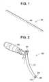
- FIG. 2illustrates an exemplary trocar guide, according to some embodiments of the present invention.
- FIG. 3is a cross-sectional view of the trocar guide shown in FIG. 2 that illustrates a curved channel for accepting a trocar or a neuro-monitoring stylette, according to some embodiments of the present invention.
- FIG. 4illustrates an exemplary cutting trocar, according to some embodiments of the present invention.
- FIG. 5illustrates an exemplary barbed/docking trocar, according to some embodiments of the present invention.
- FIG. 6illustrates an exemplary trocar handle, according to some embodiments of the present invention.
- FIG. 7is an exploded view of the trocar handle shown in FIG. 6 .
- FIG. 8is a sectional view of the trocar handle shown in FIG. 6 .
- FIG. 9illustrates the trocar handle loaded with the trocar, according to some embodiments of the present invention.
- FIG. 10is detailed sectional view of the trocar/trocar handle interaction, according to some embodiments of the present invention.
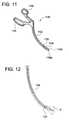
- FIG. 11illustrates an exemplary tissue separator, according to some embodiments of the present invention.
- FIG. 12illustrates exemplary working aspects of the tissue separator, according to some embodiments of the present invention.
- FIG. 13illustrates the tear-drop working end geometry of the tissue separator shown in FIG. 11 .
- FIG. 14illustrates an exemplary trocar channel cutout on the underside of the tissue separator, according to some embodiments of the present invention.
- FIG. 15illustrates exemplary anterior and dorsal tissue distracters, according to some embodiments of the present invention.
- FIG. 16illustrates an exemplary assembly of a neuro monitoring ribbon installed on the dorsal tissue distracter shown in FIG. 15 , according to some embodiments of the present invention.
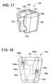
- FIG. 17illustrates an exemplary tissue distracter alignment block, according to some embodiments of the present invention.
- FIG. 18illustrates an exemplary cutout for receiving tissue distracters and exemplary internal components of a spring ball detents that lock the tissue distracters, according to some embodiments of the present invention.
- FIG. 19is an exploded view of the tissue distracter alignment block, according to some embodiments of the present invention.
- FIG. 20illustrates an exemplary way of fitting the tissue distracters inside the alignment block, according to some embodiments of the present invention.
- FIG. 21illustrates an exemplary small dilator, according to some embodiments of the present invention.
- FIG. 22an exemplary large dilator, according to some embodiments of the present invention.
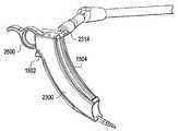
- FIG. 23an exemplary curved portal, according to some embodiments of the present invention.
- FIG. 24is another view of the curved portal shown in FIG. 23 .
- FIG. 25is a rear view of the curved portal shown in FIG. 23 .
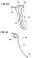
- FIG. 26illustrates an exemplary anterior awl, according to some embodiments of the present invention.
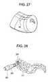
- FIG. 27illustrates an exemplary way of measurement from the midline of patient in order to locate incision, according to some embodiments of the present invention.
- FIG. 28illustrates an exemplary usage of the trocar guide to reach a “50-yard line” of a vertebral disc, according to some embodiments of the present invention.
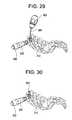
- FIG. 29illustrates the trocar with handle traveling through channel in the trocar guide, according to some embodiments of the present invention.
- FIG. 30illustrates the docked trocar with handle removed through trocar guide, according to some embodiments of the present invention.
- FIG. 31illustrates the docked trocar with trocar guide removed, according to some embodiments of the present invention.
- FIG. 32illustrates the tissue separator traveling the length of the trocar to an operating site, where the tear drop end will sweep approximately 12 mm above and below trocar, according to some embodiments of the present invention.
- FIG. 33illustrates tissue distracters with alignment block traveling the length of the trocar to the operating site, according to some embodiments of the present invention.
- FIG. 34illustrates tissue distracters being fully inserted, according to some embodiments of the present invention.
- FIG. 35illustrates the small dilator spreading the tissue distracters, according to some embodiments of the present invention.
- FIG. 36illustrates the large dilator spreading the tissue distracters over the small dilator, according to some embodiments of the present invention.
- FIG. 37illustrates the portal sliding over the dilators, according to some embodiments of the present invention.
- FIG. 38illustrates the anterior awl securing the portal, according to some embodiments of the present invention.
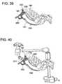
- FIG. 39illustrates the anterior awl being fully seated, according to some embodiments of the present invention.
- FIG. 40illustrates an exemplary stabilization arm being mounted to the portal, according to some embodiments of the present invention.
- FIG. 41illustrates an exemplary portal assembly with dilators and trocar being removed, according to some embodiments of the present invention.
- FIG. 42illustrates an exemplary final portal assembly and a protrusion of the anterior awl, according to some embodiments of the present invention.
- FIG. 43illustrates a patient in a prone position for performance of the disclosed procedure, according to some embodiments of the present invention.
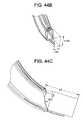
- FIGS. 44 a - cillustrate an exemplary working portal with an endoscope, displaying the endoscope's field of view, according to some embodiments of the present invention.
- the procedurebegins with placing the patient in a prone position and arranging the proper drapery to establish proper sterilization of the operation site.
- the surgeonuses a measuring device to measure a specified distance from the midline.
- the surgeonwill make a mark using some marking device as a reference point to create an incision.
- the specified distancecan be calculated using a chart or sliding scale that determines the appropriate distance to make the incision. This distance is directly related to the distance of the center of the vertebral body to the flat surface of the patient's back; given this distance along with the known arc angle of the portal and known center of the midline, the incision distance can be properly calculated.
- the trocar guidehas a curved body that has an inner cannulated channel and an offset handle.
- the instrumentmay have a small “tooth” on the inner wall to engage the spine and hold it in place.
- a neurophys stylettecan be put in the trocar guide through this process to safely monitor potential nerve disruption. Once successful docking is achieved and the optional neurophys is acceptable, the neurophys stylette is removed.
- a cutting trocar of similar shape and size as the neurophys stylette with a sharp tipis then passed through the cannulated channel in the trocar guide to pierce the spine.
- the trocar handlecan be applied to the cutting trocar.
- a malletmay also be used to advance the cutting trocar.
- the cutting trocaris then removed and replaced with the barbed trocar which is similarly sized and has a blunt tip and barbed features to anchor the trocar.
- the trocar handlecan be similarly applied to facilitate handling of the barbed trocar.
- the barbed trocarcan be “tapered” or “notched” so that the anatomy “grabs” the barbed features.
- the trocar handleis removed from the trocar and the trocar guide can be removed.
- the tissue separatoris followed down the length of the barbed trocar to the lateral surface of the spine, such as the vertebral disc annulus.
- the deviceis actuated to “peel” tissue, such as muscle, off the spine and prepare the surgical site for further instrumentation, similar to periostial elevators.
- a ringed handleis contracted and expanded to create a sweeping motion of a blade at the end of the tissue separator instrument.
- This bladecan be of tear-dropped shape to better facilitate insertion and removal of the device with minimal anatomic disruption and can be bifurcated to enable “peeling” of the tissue above and below the trocar without removing the instrument to “peel” above then reinserting to “peel” below the trocar. There can also be features to help maintain the instrument along the trocar.
- the tissue separatoris then removed.
- the tissue distractersare then assembled in the tissue distracter alignment block so that the ends of the tissue distracters are together.
- the tissue distractersare curved instruments of suitable material and geometry to move anatomy without harming or otherwise disrupting the patient's internals.
- the tips of the tissue distracterscontain a lip of approximately 5 mm in order to “catch” the tissue along the spine and maintain positioning against the lateral wall of the spine.
- the tips of the tissue distracterscan also be tapered to aid in insertion.
- the opposite ends of the tissue distractershave geometry to interact with the alignment block. This end also has outwardly curved geometry to facilitate the later part of the procedure.
- the dorsal tissue distractercan have neurophys in the form of a cable or ribbon to help monitor nerve disruption during installation and through the remainder of the operation. To aid in keeping this assembly together, an elastic polymer sheath can be slipped over assembly before insertion. The alignment block is removed.
- the small dilatoris then pushed between outwardly curved geometry through the tissue distracters and over the barbed trocar until it abuts the lateral wall of the spine. This procedure in turn expands the distance between the tissue distracters.
- a second large dilatoris then followed in a similar fashion to further distract tissue distracters. Though only two dilators are described in the above embodiment, more sequential smaller dilators can be used. The dilators are created in such fashion that they are consecutively smaller in length so that the end part from the preceding dilator protrudes from the subsequent dilator to aid in the later removal. Finger notches can be added for better grip while insertion and removal. Through this process the sheath aids in preventing tissue creep between tissue distracters.
- the curved portalis then passed over the largest dilator between the tissue distracters. Proper location is verified and adjusted using X-ray and endoscopic visualization. Once proper location is achieved, the anterior awl is passed through a channel in the curved portal to firmly “dock” the assembly to the annulus. Further, a stabilization arm can be applied to a boss feature off the curved portal. At this point, the barbed trocar and dilators can be removed. The portal is securely docked and ready to begin the technique.
- the curved portalhas slots and/or rails that interact with preceding instrumentation that also includes corresponding slots and/or rails.
- preceding instrumentationinclude, but are not limited to, trocars, tissue distracters, and/or dilators.
- Specialized curved instrumentationinserted through the curved portal, is then used to complete the surgical procedures.
- this instrumentationcan have slots and/or rails which interact with the curved portal to safely guide instrumentation to the surgical site.
- these proceduresinclude removing the annulus, cleaning and preparing the disc space, inserting and securing the implant.
- instrumentationcan include an annulotomy knife, disc whisk, curettes, chisels, implant trials and curved inserting devices.
- proper location of the implantis then confirmed via x-ray.
- the curved portal and tissue distractersare removed to complete the procedure. Posterior fixation can be then begin, if needed.
- the present inventionrelates to a guided lumbar interbody fusion procedure and instrumentation.
- FIG. 1illustrates an exemplary measuring device 100 for locating a point of entry for delivering of instrumentation, according to some embodiments of the present invention.
- the measuring device 100can be a ruler.
- the measuring device 100can be a straight x-ray ruler with cutout designations 102 that include notches that can be seen in a fluoroscopy image.
- the patientis placed in a prone position, as illustrated in FIG. 43 .
- the surgeonmeasures a specified distance from the midline of the back of the patient, as shown in FIG. 27 .
- the surgeonmakes a mark using a marking device as a reference point to create an incision.
- the incisioncan be about 4 to about 50 millimeters (“mm”) wide.
- the surgeoncan use a chart, a sliding scale or any other methodology to determine location of the incision and the width of the incision.
- the surgeoncan also decide as to the angle of the portal through which the surgery will be performed.
- FIG. 2illustrates an exemplary trocar guide 200 , according to some embodiments of the present invention.
- FIG. 3is a cross-sectional view of the trocar guide 200 shown in FIG. 2 that illustrates a curved channel 302 for accepting a trocar or a neuro-monitoring stylette, according to some embodiments of the present invention.
- the trocarwill be further discussed below with regard to FIG. 4 .
- the trocar guide 200includes a handle 202 and a shaft 212 .
- the shaft 212includes a proximal end 204 and a distal end 206 .
- the proximal end 204includes a flat surface that the surgeon can use to hammer in the trocar guide 200 .
- the distal end 206further includes a tip 208 that can be configured to include a neuro-monitoring element.
- the distal end 206also includes a rasping surface 210 to help anchor against lateral wall of the spine.
- the angle A that is formed between the plane of the handle and the plane that is perpendicular to the flat surface at the proximal end 204is approximately 100 degrees. As can be understood by one skilled in the art, angle A can have any other value.
- the handle 202can be manufactured from silicone and can be further configured to comfortably guide the proximal end of the instrument to the centerline of the vertebral body. As can be understood by one skilled in the art, other materials can be used for the handle 202 .
- the trocar guide 202includes a channel 302 that is configured to accommodate placement of the trocar or a stylette.
- the channel 302is disposed inside the shaft 202 and is configured to track the curvature of the trocar guide's shaft 202 .
- Such curved channel 302allows insertion of a curved trocar (as shown in FIGS. 4-5 ).
- FIGS. 4-5illustrate various exemplary trocars, according to some embodiments of the present invention.
- FIG. 4illustrates an exemplary cutting trocar, according to some embodiments of the present invention.
- the cutting trocar 400includes a distal end 402 , a proximate end 404 and a shaft 410 disposed between the distal end 402 and the proximate end 404 .
- the shaft 410is configured to be curved in a similar fashion as the trocar guide 200 .
- the proximate end 404includes a pointed tip.
- the distal end 402can be configured to include a grooved portion 414 that allows the handle 600 to be secured to the trocar 400 .
- the cutting trocar 400(shown in FIG. 4 ) is inserted down the trocar guide's channel 302 (shown in FIG.
- the cutting trocar 400is removed from the channel 302 and a barbed trocar 500 (shown in FIG. 5 ) is inserted, as shown in FIG. 29 .
- FIG. 5illustrates an exemplary barbed/docking trocar, according to some embodiments of the present invention.
- the barbed trocar 500includes a distal end 502 , a proximate end 504 , a shaft 510 disposed between the distal end 502 and the proximate end 504 .
- the shaft 510is configured to be curved in a similar fashion as the trocar guide 200 .
- the proximate end 504includes a pointed tip and barbs 518 that can be configured to secure the barbed trocar 500 to the spine.
- the distal end 502 of the trocar 500can be configured to include a grooved portion 514 that allows the handle 600 to be secured to the trocar 500 .
- the barbed trocaris inserted down the trocar guide channel 302 (shown in FIG. 3 ) in order to mount to the lateral wall of the spine to provide a guide to the surgical site.
- a handle 600shown in FIGS. 6-8
- the trocar guide 200is then removed from the incision, as shown in FIG. 31 .
- FIGS. 6-8illustrate an exemplary handle 600 , according to some embodiments of the present invention.
- FIG. 6illustrates the assembled trocar handle 600 .
- FIG. 7is an exploded view of the trocar handle shown in FIG. 6 .
- FIG. 8is a sectional view of the trocar handle shown in FIG. 6 .
- the trocar handle 600includes a handle portion 702 , spring 704 , bottom portion 706 , a top portion 708 , a shaft 710 , and a locking pin 712 .
- the handle portion 702can be configured to be manufactured from silicon or any other suitable material(s).
- the top portion 708includes a hardened surface 715 . The surgeon can use surface 715 to hammer in the trocars 400 and 500 .
- the surface 715can be manufactured from any metal or any other suitable material(s).
- the spring 704can be configured to control locking of the components within handle portion 702 .
- the handle portion 702includes an opening 721 .
- the shaft 710includes an opening 723 .
- the openings 721 , and 723are configured to be sized to accommodate insertion of the locking pin 712 .
- the shaft 710is configured to be inserted through the bottom portion 706 , the spring 704 , the handle portion 702 , and the top portion 708 . Once all the portions are assembled together, the locking pin 712 is inserted to secure the handle 600 together, as illustrated in FIGS. 6 and 8 .
- the shaft 710 of the handle 600includes a hollow interior configured to accommodate placement of the trocar.
- the shaft 710further includes a locking pin 1010 that is configured to interact with the grooves 514 of the trocar 500 and lock the trocar 500 inside the shaft 710 .
- the locking pin 1010is shifted and the trocar 500 is released from the shaft 710 .
- other ways of securing the trocar 500 inside the handle 600are possible.
- FIG. 9illustrates the trocar handle loaded with the barbed trocar 500 .
- FIG. 10is detailed sectional view of the trocar 500 and trocar handle 600 interaction, according to some embodiments of the present invention.
- trocar 400can also be loaded into the handle 600 in the same fashion as the trocar 500 .
- FIGS. 11-14illustrate an exemplary tissue separator 1100 , according to some embodiments of the present invention.
- FIG. 11is a general view of the tissue separator 1100 .
- FIG. 12illustrates exemplary working aspects of the tissue separator 1100 , according to some embodiments of the present invention.
- FIG. 13illustrates the tear-drop working end geometry of the tissue separator 1100 .
- FIG. 14illustrates an exemplary trocar channel cutout 1402 on the underside of the tissue separator 1100 .
- the tissue separator 1100is guided down the barbed trocar 500 (shown in FIG. 5 ) to the vertebral wall and is actuated to separate tissue from the vertebral wall, as illustrated in FIG. 32 .
- the trocar channel cutout on the underside of the tissue separatorcan be used to aid in guiding the tissue separator down the barbed trocar.
- the tissuecan be separated above the trocar and then separated below the trocar.
- the tissue separator 1100includes a shaft 1102 , handles 1104 , 1106 , distal portion 1108 have separators 1109 a and 1109 b .
- the handles 1104 , 1106are hingedly coupled to the shaft 1102 at the pivotal connection 1120 .
- the handles 1104 , 1106are configured to control movement of the separators 1109 a , 1109 b .
- the shaft 1102is configured to have a similar curved geometry as the trocar guide 200 , as shown in FIG. 2 .
- the separators 1109 ( a, b )are configured to remove or peel tissue at the location of the docked barbed trocar 500 (shown in FIG. 5 ). Such removal is possible through up and down pivotal movement B as illustrated in FIG.
- the movement Bis possible through rotational motion of the handles 1104 , 1106 in a scissor like fashion.
- one of the handles 1104 , 1106e.g., 1106
- the other handlee.g., 1104
- other actuation methods for this devicecan be used.
- the distance between separators 1109 a and 1109 bcan be configured to accommodate the diameter of the trocar 500 .
- the tissue separator 1100can be configured to be slid down the trocar 500 using channel 1402 (illustrated in FIG. 14 ).
- the channel 1402is configured to be disposed on the back side of the tissue separator 1100 and allows the surgeon to guide the tissue separator 1100 to remove tissue(s) surrounding the trocar 500 . The removal is accomplished through pivotal movement of the separators 1109 ( a, b ).
- the tissue separator 1100can be used to separate psoas muscle tissue. As can be understood by one skilled in the art, the separator 1100 can be used for any other tissue separation and/or removal.
- FIG. 15illustrates an exemplary anterior tissue distracter 1502 and dorsal tissue distracter 1504 , according to some embodiments of the present invention.
- FIG. 16illustrates an exemplary assembly of a neuro monitoring ribbon 1602 installed on the dorsal tissue distracter 1504 , according to some embodiments of the present invention.
- the distracterscan be also referred to as distraction ramps.
- the distracterscan be delivered as a single unit along the inserted barbed trocar 500 (shown in FIG. 5 ), where the trocar 500 is placed between the distracters, to the vertebral wall.
- the distraction ramps 1502 , 1504are delivered together as a single unit in a balloon, which keeps the ramps joined and prevents encroachment of soft tissue between the ramps.
- the structure of the ramp 1502is similar to the ramp 1504 .
- the ramp 1504includes a proximal end 1511 and a distal end 1513 .
- the ramp 1504further includes a rail/slot (shown as rail/slot 1506 on ramp 1502 ).
- the rail/slot 1506is configured to be disposed on the interior side of the ramps 1502 and 1504 and further configured to accommodate guiding of instruments (such as trocars or dilators) down to the procedure working area at the surgical site.
- the rail/slot on each rampis disposed between the proximal and distal ends and is further configured to create openings 1530 at the proximal end 1511 (formed by two rail/slot portions 1530 a and 1530 b ) and 1531 (formed by two portions 1531 a and 1531 b ) at the distal end 1508 of the ramps, when the ramps' interior sides are joined together. As stated above, such openings are configured to accommodate placement of instruments between the ramps.
- the ramp 1504further includes a lip 1513 (the ramp 1502 includes a lip 1510 ) that is configured to help navigate through the soft tissue and “grab” the tissue.
- the lip 1513 (and/or lip 1510 ) on the rampare configured to push away the tissue allowing the ramps to approach the wall of the vertebral disc.
- the rampsinclude a monitoring element 1602 disposed on the ramp 1504 (also referred to as a dorsal ramp), as illustrated in FIG. 16 .
- the monitoring element 1602can be configured to be any conventional neural monitoring element that allows detection of approaching neural tissue via application of current.
- the element 1602can be configured to be coupled to an electrical supply (not shown) that delivers current to the tissue via element 1602 and upon detection of a response, the element 1602 can determine whether neural tissue is proximate to the element 1602 and/or the ramp 1504 (and/or 1502 ). Further, the neuron-monitoring element 1602 can be used to preserve the integrity of neural structures and provide an early detection to prevent or minimize damage to those structures during surgical procedures. As can be understood by one skilled in the art, both ramps 1502 and 1504 can be configured to include element 1602 .
- the distraction ramps 1502 and 1504can have variable lengths and a distracter alignment block 1700 , illustrated in FIG. 17 , can be used to align the ramps 1502 and 1504 for proper insertion and approach to the surgical site (as shown in FIG. 33 ).
- FIGS. 18-20are various views of the distracter alignment block 1700 .
- FIG. 18is a cross-sectional view of the block 1700 showing tissue distracters and internal components of block 1700 that include a spring ball detents that lock the tissue distracters, according to some embodiments of the present invention.
- FIG. 19is an exploded view of the tissue distracter alignment block 1700 .
- FIG. 20illustrates an exemplary way of fitting the tissue distracters inside the alignment block 1700 .
- block 1700includes a housing 1702 having an open channel 1704 disposed inside the housing 1702 .
- the open channel 1704is further configured to be disposed between the top and the bottom of the housing 1702 .
- the channel 1704includes grooves 1706 and 1708 disposed on each side of the open channel 1704 , as shown in FIG. 17 .
- the grooves 1706 and 1708are configured to accommodate placement of the proximal ends of the distraction ramps 1502 and 1504 , respectively. Referring to FIGS.
- the proximal ends of the ramps 1502 , 1504include protruding portions that are configured to be curved away from their interior portions and are sized to fit inside the open channel 1704 and the grooves 1706 and 1708 , respectively.
- the ramps 1502 , 1504can be configured to be inserted into the channel 1704 simultaneously or one after the other. Since, the channel 1704 is open on one side of the housing 1702 and closed on the other side of the housing 1702 , the ramps 1502 , 1504 are prevented from sliding out after being inserted into the grooves 1706 , 1708 .
- locking mechanisms 1720 , 1722are configured to be disposed within the openings/holes 1724 , 1726 , respectively, which are further accessible through the top of the housing 1702 of the block 1700 , as illustrated in FIG. 17 .
- Each one of the locking mechanisms 1720 , 1722includes a ball 1802 ( a, b ,), a spring 1804 ( a, b ), and a locking pin 1806 ( a, b ).
- the balls 1802are configured to be inserted first into the openings 1724 , 1726 , followed by the spring 1804 , and then pins 1806 .
- the pin 1806 ais configured to be shorter than the pin 1806 b since the groove 1708 is disposed lower than the groove 1706 along the open channel 1704 .
- the pins 1806can further include a locking device that prevents the pins from accidentally falling out of the openings 1724 , 1726 .
- a locking devicethat prevents the pins from accidentally falling out of the openings 1724 , 1726 .
- FIG. 20illustrates the ramps 1502 , 1504 being secured inside the alignment block 1700 .
- the channel 1704disposed on the interior portion of the housing 1702 , is configured to be wider near the top of the housing 1702 and narrower near the bottom of the housing 1702 , as illustrated in FIG. 20 . This allows to further secure the ramps 1502 , 1504 inside the housing 1702 .
- the alignment blockcan be removed to allow tissue distraction, which can be accomplished using distraction ramps 1502 , 1504 , and insertion of dilators (discussed below with regard to FIGS. 21-22 ), as shown in FIG. 34 .
- FIGS. 21-22illustrate exemplary dilators that are configured to be guided down the barbed trocar 500 (shown in FIG. 5 ) and between distraction ramps 1502 , 1504 using rail/slot 1506 .
- FIG. 21illustrates an exemplary small dilator 2100 , according to some embodiments of the present invention.
- FIG. 22an exemplary large dilator 2200 , according to some embodiments of the present invention.
- the small dilator 2100is initially guided down over the barbed trocar 500 (shown in FIG. 5 ) and between the distraction ramps 1502 , 1504 .
- the large dilator 2200is guided down over the small dilator 2100 and also between the distraction ramps 1502 , 1504 .
- Both dilators 2100 and 2200are further configured to be curved in a similar fashion as the trocar 500 (shown in FIG. 5 ).
- the curvature radius of the trocar 500 , dilators 2100 , 2200 , and other instruments discussed in the present applicationare configured to substantially match in order to prevent wobbling of these instruments when they are being advanced toward the surgical site.
- the dilator 2200can be shorter than the dilator 2100 , which can further accommodate placement and removal of the dilators.
- the dilatorscan be manufactured from any biocompatible material such as, but not limited to stainless steel, titanium, aluminum, and/or polyetheretherketone (“PEEK”).
- the materialcan be also non-conductive radiolucent material, and can be hammered with a mallet to advance it to the surgical site.
- small dilator 2100includes a housing 2102 having an open channel 2104 .
- the channel 2104is sized to accommodate insertion of the trocar 500 .
- the channel 2104is disposed throughout the interior of the housing 2102 and begins with an opening 2106 at the top (or near the proximal end) of the dilator 2100 and ends with an opening 2108 at the bottom (or near the distal end) of the dilator 2100 .
- the dilator 2100is configured to be placed over the trocar 500 (shown in FIG. 5 ) with the opening 2108 and then slid down the trocar 500 until the dilator 2100 reaches the surgical site, as shown in FIG. 35 .
- the housing 2102 of the dilator 2100further includes a plurality of grasping ribs 2120 disposed near the proximal end of the dilator.
- the grasping ribs 2120are further configured to allow holding the dilator 2100 when the dilator is being slid down the trocar 500 .
- the channel 2104has a round cross-section in order to accommodate placement of the trocar 500 .
- the dilator 2100has a square cross-section. As can be understood by one skilled in the art, the cross-sections of the channel 2104 and the dilator 2100 can vary as desired.
- large dilator 2200includes a housing 2202 having an open rail/slot 2204 .
- the rail/slot 2204is sized to accommodate insertion of the small dilator 2100 .
- the rail/slot 2204is disposed throughout the exterior of the housing 2202 and begins with an opening 2206 at the top (or near the proximal end) of the dilator 2200 and ends with an opening 2208 at the bottom (or near the distal end) of the dilator 2200 .
- the dilator 2200is configured to be placed over the dilator 2100 (shown in FIG.
- the housing 2202 of the dilator 2200further includes a plurality of grasping ribs 2220 disposed near the proximal end of the dilator.
- the grasping ribs 2220are further configured to allow holding the dilator 2200 when the dilator is being slid down the small dilator 2100 .
- the rail/slot 2204has a square rail/slot cross-section in order to accommodate placement of the small dilator 2100 .
- the dilator 2200has a square cross-section. As can be understood by one skilled in the art, the cross-sections of the rail/slot 2204 and the dilator 2200 can vary as desired.
- FIGS. 23-25illustrate an exemplary curved portal 2300 , according to some embodiments of the present invention.
- FIG. 23illustrates the curved portal 2300 .
- FIG. 24is another view of the curved portal 2300 .
- FIG. 25is a rear view of the curved portal 2300 .
- the portal 2300includes a housing 2302 disposed between the proximate end 2306 and a distal end 2308 .
- the housing 2302also includes an interior channel 2304 that is disposed between an opening at the proximate end 2306 and an opening at the distal end 2308 .
- the channel 2304is sized to accommodate insertion over the large dilator 2200 (shown in FIG. 22 ) and subsequent instrumentation.
- Channel 2304may contain additional rail/slots to aid in guiding instrumentation.
- the housing 2302also includes an outside rail/slot 2312 disposed on the rear portion of the working portal 2300 , as illustrated in FIGS. 23-25 .
- the rail/slot 2312is configured to extend through the whole housing 2302 and terminate at the distal end 2308 at an opening 2310 .
- the opening 2310is further configured to accommodate protrusion of an awl 2600 (shown in FIG. 26 ) upon its insertion through the rail/slot 2312 .
- the outside rail/slot 2312 and 2340are configured to accommodate insertion of the working portal 2300 between tissue distracters 1502 and 1504 .
- the outside rail/slot 2312is also disposed between the proximate end 2306 and the distal end 2308 .
- the distal end 2308has a curved open end structure that can be configured to accommodate mounting to the lateral wall of the spine.
- the width and/or height of the working portal 2300can be in the range of 5 mm to 30 mm; alternately, between 10 mm and 25 mm; alternately, between 15 mm and 25 mm; alternately, between 18 mm and 23 mm. In some embodiments, the width of the working portal 2300 can be 20.3 mm. In some embodiments, the height of the portal 2300 can be 24 mm. In some embodiments, the width and/or height of the channel 2304 can be in the range of 5 mm to 30 mm; alternately, between 10 mm and 25 mm; alternately, between 15 mm and 25 mm; alternately, between 18 mm and 23 mm. In some embodiments, the width of the channel 2304 can be 17 mm.
- the height of the channel 2304can be 19 mm.
- the curvature radius of the working portal 2300can be in above 3 mm. In some embodiments, the curvature radius of the working portal 2300 can be very large, thereby the working portal 2300 having only a slightly curved shape. In some embodiments, the curvature radius of the working portal 2300 is 12 cm.
- the working portal 2300can also accommodate placement of an endoscope 4400 that allows viewing of the surgical area, as illustrated in FIG. 44 a - c .
- Direct visualizationis via a flexible or fixed radius endoscope.
- Intra-operative electrophysiological monitoring and fluoroscopyare utilized.
- the endoscope 4400can be disposed along one of the walls of the working portal 2300 , as shown in FIG. 44 a , and can be mounted on the holding arm 4402 that secures the working portal 2300 .
- the endoscope viewing areacan be on the order of about 50.8 mm by 15.875 mm by 28.575 mm.
- FIG. 44 cillustrates the field of view of the endoscope.
- the working portal 2300can be configured to have a substantially square or rectangular cross-section.
- the cross-section of the working portal 2300can have any other shape, e.g., elliptical, round, polygonal, or any other desired shape. Because of the curvature of the working portal 2300 , it can accommodate insertion of an implant at a direction that is substantially perpendicular to the surface of the body of the patient. Once the implant is inserted at the proximate end of the working portal 2300 , it is advanced toward the surgical site down the interior channel of the working portal 2300 .
- the direction of movement of the implantchanges from substantially perpendicular or angular with regard to the body of the patient to substantially lateral or transverse. This allows the surgeon easily manipulate insertion and placement of the implant without having to create a large incision in the patient.
- the working portal 2300can be configured to accommodate insertion of an implant having the following dimensions: height in the range of 8 mm to 18 mm, an anterior-posterior depth of in the range of 8 mm to 30 mm (alternately, between 10 mm to 25 mm; alternately, between 15 mm to 25 mm; alternately, between 18 mm to 23 mm; in some embodiments, the depth can be approximately 22 mm), and a lateral width in the range of 20 mm to 70 mm (alternately, between 30 mm to 65 mm; alternately, between 40 mm to 50 mm; alternately, between 45 mm to 55 mm).
- the working portal 2300can be manufactured from any biocompatible material such as, but not limited to stainless steel, titanium, aluminum, and/or PEEK. As can be understood by one skilled in the art, the portal 2300 can be manufactured from any other suitable material(s).
- FIG. 37illustrates the portal 2300 prior to insertion of anterior awl 2600 .
- the trocar 500along with the portal 2300 , the trocar 500 , the dilators 2100 and 2200 , and the ramps 1502 and 1504 are also inserted.
- the awl 2600contains a handle configured to protrude away from the distal end 2308 of the portal 2300 (as shown in FIGS. 38-39 ).
- the awl 2600includes a curved shaft 2602 disposed between a handle 2606 at the proximate end of the awl 2600 and a barbed tip 2604 at the distal end of the awl 2600 .
- the barbed tip 2604is configured to make an incision in the vertebral wall.
- the shaft 2602is configured to be curved in a similar fashion as other instruments (e.g., the trocars, dilators, etc.) in order to allow adequate advancement of the awl 2600 towards the surgical site.
- the awl 2600is manufactured from any biocompatible material such as, but not limited to stainless steel, titanium, aluminum, and/or PEEK.
- the materialcan be also a radio-opaque material.
- the awl 2600can be manufactured from any other suitable materials.
- the working portal constructcan be further stabilized using a stabilization arm 2314 (e.g., StrongArm, manufactured by Mediflex).
- the arm 2314is coupled to a stationary equipment in the operating room, such as the operating table. As can be understood by one skilled in the art, any other holding arms can be used.
- the implantsmay include, but are not limited to: bone screws, plates, interbody devices, artificial discs, or any other implants.
- the present invention's device and methodologycan be used in any number of surgical procedures, including nucleus replacement, total disc replacement, interbody fusion, discectomy, neural decompression, implant delivery (whether for fixation purposes and/or stabilization), or any other procedure.
Landscapes
- Health & Medical Sciences (AREA)
- Surgery (AREA)
- Life Sciences & Earth Sciences (AREA)
- Biomedical Technology (AREA)
- Nuclear Medicine, Radiotherapy & Molecular Imaging (AREA)
- Engineering & Computer Science (AREA)
- Heart & Thoracic Surgery (AREA)
- Medical Informatics (AREA)
- Molecular Biology (AREA)
- Animal Behavior & Ethology (AREA)
- General Health & Medical Sciences (AREA)
- Public Health (AREA)
- Veterinary Medicine (AREA)
- Pathology (AREA)
- Surgical Instruments (AREA)
Abstract
Description
Claims (18)
Priority Applications (3)
| Application Number | Priority Date | Filing Date | Title |
|---|---|---|---|
| US12/069,721US8152714B2 (en) | 2007-02-09 | 2008-02-11 | Curviliner spinal access method and device |
| US12/460,795US8425602B2 (en) | 2007-02-09 | 2009-07-23 | Curvilinear spinal access method and device |
| US13/415,186US20120215229A1 (en) | 2007-02-09 | 2012-03-08 | Curvilinear spinal access method and device |
Applications Claiming Priority (2)
| Application Number | Priority Date | Filing Date | Title |
|---|---|---|---|
| US90055407P | 2007-02-09 | 2007-02-09 | |
| US12/069,721US8152714B2 (en) | 2007-02-09 | 2008-02-11 | Curviliner spinal access method and device |
Related Child Applications (2)
| Application Number | Title | Priority Date | Filing Date |
|---|---|---|---|
| US12/460,795Continuation-In-PartUS8425602B2 (en) | 2007-02-09 | 2009-07-23 | Curvilinear spinal access method and device |
| US13/415,186ContinuationUS20120215229A1 (en) | 2007-02-09 | 2012-03-08 | Curvilinear spinal access method and device |
Publications (2)
| Publication Number | Publication Date |
|---|---|
| US20080221586A1 US20080221586A1 (en) | 2008-09-11 |
| US8152714B2true US8152714B2 (en) | 2012-04-10 |
Family
ID=39358070
Family Applications (2)
| Application Number | Title | Priority Date | Filing Date |
|---|---|---|---|
| US12/069,721Expired - Fee RelatedUS8152714B2 (en) | 2007-02-09 | 2008-02-11 | Curviliner spinal access method and device |
| US13/415,186AbandonedUS20120215229A1 (en) | 2007-02-09 | 2012-03-08 | Curvilinear spinal access method and device |
Family Applications After (1)
| Application Number | Title | Priority Date | Filing Date |
|---|---|---|---|
| US13/415,186AbandonedUS20120215229A1 (en) | 2007-02-09 | 2012-03-08 | Curvilinear spinal access method and device |
Country Status (4)
| Country | Link |
|---|---|
| US (2) | US8152714B2 (en) |
| EP (1) | EP2114257B1 (en) |
| JP (1) | JP5271281B2 (en) |
| WO (1) | WO2008097665A1 (en) |
Cited By (18)
| Publication number | Priority date | Publication date | Assignee | Title |
|---|---|---|---|---|
| US20110112586A1 (en)* | 2009-11-11 | 2011-05-12 | Jeffrey Allen Guyer | Methods and devices for portal fixation to the spine |
| US20110184515A1 (en)* | 2004-08-11 | 2011-07-28 | Nonliner Technologies Ltd. | Devices For Introduction Into A Body Via A Substantially Straight Conduit To Form A Predefined Curved Configuration, And Methods Employing Such Devices |
| US20110184464A1 (en)* | 2010-01-27 | 2011-07-28 | Warsaw Orthopedic, Inc. | Systems and methods for minimally invasive stabilization of bony structures |
| US20150080755A1 (en)* | 2012-05-16 | 2015-03-19 | Avery M. Jackson, III | Illuminated Endoscopic Pedicle Probe With Electromyographic Monitoring |
| US9066701B1 (en) | 2012-02-06 | 2015-06-30 | Nuvasive, Inc. | Systems and methods for performing neurophysiologic monitoring during spine surgery |
| US20150342621A1 (en)* | 2014-05-29 | 2015-12-03 | Avery M. Jackson, III | Illuminated endoscopic pedicle probe with dynamic real time monitoring for proximity to nerves |
| US9204906B2 (en) | 2009-10-22 | 2015-12-08 | Nuvasive, Inc. | Posterior cervical fusion system and techniques |
| US9486133B2 (en) | 2010-08-23 | 2016-11-08 | Nuvasive, Inc. | Surgical access system and related methods |
| US9655505B1 (en) | 2012-02-06 | 2017-05-23 | Nuvasive, Inc. | Systems and methods for performing neurophysiologic monitoring during spine surgery |
| US9757067B1 (en) | 2012-11-09 | 2017-09-12 | Nuvasive, Inc. | Systems and methods for performing neurophysiologic monitoring during spine surgery |
| US9795367B1 (en) | 2003-10-17 | 2017-10-24 | Nuvasive, Inc. | Surgical access system and related methods |
| US9943342B2 (en) | 2015-05-11 | 2018-04-17 | Providence Medical Technology, Inc. | Methods for implanting a bone screw |
| US10045768B2 (en) | 2014-07-06 | 2018-08-14 | Javier Garcia-Bengochea | Methods and devices for surgical access |
| US10098674B2 (en) | 2009-10-22 | 2018-10-16 | Nuvasive, Inc. | System and method for posterior cervical fusion |
| US10368881B2 (en) | 2016-06-03 | 2019-08-06 | Quandary Medical, Llc | Method and apparatus for minimally invasive posterolateral spinal fusion |
| US10398451B2 (en) | 2012-05-16 | 2019-09-03 | Optical Spine, Llc | Illuminated endoscopic pedicle probe with replaceable tip |
| US10687830B2 (en) | 2015-07-06 | 2020-06-23 | Javier Garcia-Bengochea | Methods and devices for surgical access |
| US10874447B2 (en) | 2015-05-11 | 2020-12-29 | Providence Medical Technology, Inc. | Bone screw and implant delivery device |
Families Citing this family (97)
| Publication number | Priority date | Publication date | Assignee | Title |
|---|---|---|---|---|
| US7857813B2 (en) | 2006-08-29 | 2010-12-28 | Baxano, Inc. | Tissue access guidewire system and method |
| US20100331883A1 (en) | 2004-10-15 | 2010-12-30 | Schmitz Gregory P | Access and tissue modification systems and methods |
| US8048080B2 (en) | 2004-10-15 | 2011-11-01 | Baxano, Inc. | Flexible tissue rasp |
| US8613745B2 (en) | 2004-10-15 | 2013-12-24 | Baxano Surgical, Inc. | Methods, systems and devices for carpal tunnel release |
| US8221397B2 (en) | 2004-10-15 | 2012-07-17 | Baxano, Inc. | Devices and methods for tissue modification |
| US20110190772A1 (en) | 2004-10-15 | 2011-08-04 | Vahid Saadat | Powered tissue modification devices and methods |
| US8062300B2 (en) | 2006-05-04 | 2011-11-22 | Baxano, Inc. | Tissue removal with at least partially flexible devices |
| US8257356B2 (en) | 2004-10-15 | 2012-09-04 | Baxano, Inc. | Guidewire exchange systems to treat spinal stenosis |
| JP5243034B2 (en) | 2004-10-15 | 2013-07-24 | バクサノ,インク. | Tissue removal device |
| US7959577B2 (en) | 2007-09-06 | 2011-06-14 | Baxano, Inc. | Method, system, and apparatus for neural localization |
| US9247952B2 (en) | 2004-10-15 | 2016-02-02 | Amendia, Inc. | Devices and methods for tissue access |
| US9101386B2 (en) | 2004-10-15 | 2015-08-11 | Amendia, Inc. | Devices and methods for treating tissue |
| US8002777B2 (en)* | 2005-06-09 | 2011-08-23 | Biomet Manufacturing Corp. | Instrumentation and method for implanting a curved stem tibial tray |
| US8366712B2 (en) | 2005-10-15 | 2013-02-05 | Baxano, Inc. | Multiple pathways for spinal nerve root decompression from a single access point |
| US8062298B2 (en) | 2005-10-15 | 2011-11-22 | Baxano, Inc. | Flexible tissue removal devices and methods |
| US8092456B2 (en) | 2005-10-15 | 2012-01-10 | Baxano, Inc. | Multiple pathways for spinal nerve root decompression from a single access point |
| US20070162132A1 (en) | 2005-12-23 | 2007-07-12 | Dominique Messerli | Flexible elongated chain implant and method of supporting body tissue with same |
| US8034110B2 (en) | 2006-07-31 | 2011-10-11 | Depuy Spine, Inc. | Spinal fusion implant |
| WO2008070863A2 (en) | 2006-12-07 | 2008-06-12 | Interventional Spine, Inc. | Intervertebral implant |
| US7879039B2 (en)* | 2006-12-28 | 2011-02-01 | Mi4Spine, Llc | Minimally invasive interspinous process spacer insertion device |
| US8414587B2 (en) | 2007-01-26 | 2013-04-09 | Laurimed, Llc | Styli used to position device for carrying out selective discetomy |
| US7993344B2 (en)* | 2007-03-26 | 2011-08-09 | Warsaw Orthopedic, Inc. | Guide and method for inserting an elongated member into a patient |
| US8900307B2 (en) | 2007-06-26 | 2014-12-02 | DePuy Synthes Products, LLC | Highly lordosed fusion cage |
| US8192436B2 (en) | 2007-12-07 | 2012-06-05 | Baxano, Inc. | Tissue modification devices |
| EP2237748B1 (en) | 2008-01-17 | 2012-09-05 | Synthes GmbH | An expandable intervertebral implant |
| WO2009124192A1 (en) | 2008-04-02 | 2009-10-08 | Laurimed, Llc | Methods and devices for delivering injections |
| US8936641B2 (en) | 2008-04-05 | 2015-01-20 | DePuy Synthes Products, LLC | Expandable intervertebral implant |
| US8398641B2 (en) | 2008-07-01 | 2013-03-19 | Baxano, Inc. | Tissue modification devices and methods |
| US9314253B2 (en) | 2008-07-01 | 2016-04-19 | Amendia, Inc. | Tissue modification devices and methods |
| US8409206B2 (en) | 2008-07-01 | 2013-04-02 | Baxano, Inc. | Tissue modification devices and methods |
| AU2009271047B2 (en) | 2008-07-14 | 2014-04-17 | Baxano Surgical, Inc. | Tissue modification devices |
| US8992558B2 (en) | 2008-12-18 | 2015-03-31 | Osteomed, Llc | Lateral access system for the lumbar spine |
| US20100160947A1 (en)* | 2008-12-18 | 2010-06-24 | IMDS, Inc. | Systems and methods for dilation and dissection of tissues |
| US8906094B2 (en)* | 2008-12-31 | 2014-12-09 | Spineology, Inc. | System and method for performing percutaneous spinal interbody fusion |
| US20100198140A1 (en)* | 2009-02-05 | 2010-08-05 | Kevin Jon Lawson | Percutaneous tools and bone pellets for vertebral body reconstruction |
| EP2405823A4 (en) | 2009-03-13 | 2012-07-04 | Baxano Inc | Flexible neural localization devices and methods |
| US9526620B2 (en) | 2009-03-30 | 2016-12-27 | DePuy Synthes Products, Inc. | Zero profile spinal fusion cage |
| US8394102B2 (en) | 2009-06-25 | 2013-03-12 | Baxano, Inc. | Surgical tools for treatment of spinal stenosis |
| JP2012533383A (en)* | 2009-07-20 | 2012-12-27 | ザ エーデルマン リサーチ リミテッド | Surgical access device |
| US20120245914A1 (en)* | 2009-10-19 | 2012-09-27 | Siemens Aktiengesellschaft | Hollow needle positioning system |
| US9028553B2 (en) | 2009-11-05 | 2015-05-12 | DePuy Synthes Products, Inc. | Self-pivoting spinal implant and associated instrumentation |
| US8454623B2 (en)* | 2009-11-11 | 2013-06-04 | Alphatec Spine, Inc | Instrument for insertion and deployment of features on an implant |
| US9393129B2 (en) | 2009-12-10 | 2016-07-19 | DePuy Synthes Products, Inc. | Bellows-like expandable interbody fusion cage |
| US9265622B2 (en) | 2010-03-22 | 2016-02-23 | Amendia, Inc. | Percutaneous arthrodesis method and system |
| US8728162B2 (en) | 2010-04-15 | 2014-05-20 | Osteomed, Llc | Direct lateral spine system instruments, implants and associated methods |
| US8956414B2 (en) | 2010-04-21 | 2015-02-17 | Spinecraft, LLC | Intervertebral body implant, instrument and method |
| US8506635B2 (en)* | 2010-06-02 | 2013-08-13 | Warsaw Orthopedic, Inc. | System and methods for a laterally expanding implant |
| US9907560B2 (en) | 2010-06-24 | 2018-03-06 | DePuy Synthes Products, Inc. | Flexible vertebral body shavers |
| US8979860B2 (en) | 2010-06-24 | 2015-03-17 | DePuy Synthes Products. LLC | Enhanced cage insertion device |
| US8623091B2 (en) | 2010-06-29 | 2014-01-07 | DePuy Synthes Products, LLC | Distractible intervertebral implant |
| CN103068327B (en) | 2010-06-30 | 2015-08-05 | 劳瑞弥徳有限责任公司 | For excising and withdraw from the apparatus and method of tissue |
| US8685052B2 (en) | 2010-06-30 | 2014-04-01 | Laurimed, Llc | Devices and methods for cutting tissue |
| US9402732B2 (en) | 2010-10-11 | 2016-08-02 | DePuy Synthes Products, Inc. | Expandable interspinous process spacer implant |
| US9271754B2 (en)* | 2010-12-16 | 2016-03-01 | Boston Scientific Scimed, Inc. | Movable curved needle for delivering implants and methods of delivering implants |
| US9700425B1 (en)* | 2011-03-20 | 2017-07-11 | Nuvasive, Inc. | Vertebral body replacement and insertion methods |
| EP3485851B1 (en) | 2011-03-22 | 2021-08-25 | DePuy Synthes Products, LLC | Universal trial for lateral cages |
| US9345472B2 (en) | 2011-09-02 | 2016-05-24 | Boston Scientific Scimed, Inc. | Multi-arm tool for delivering implants and methods thereof |
| JP6302842B2 (en)* | 2012-01-06 | 2018-04-11 | シン, ジワン スティーブンSINGH, Jiwan Steven | Insertion device and insertion system for laparoscopic instruments |
| WO2013119336A1 (en) | 2012-02-10 | 2013-08-15 | Laurimed, Llc | Vacuum powered rotary devices and methods |
| US9226764B2 (en) | 2012-03-06 | 2016-01-05 | DePuy Synthes Products, Inc. | Conformable soft tissue removal instruments |
| US9084591B2 (en) | 2012-10-23 | 2015-07-21 | Neurostructures, Inc. | Retractor |
| US10022245B2 (en) | 2012-12-17 | 2018-07-17 | DePuy Synthes Products, Inc. | Polyaxial articulating instrument |
| US9717601B2 (en) | 2013-02-28 | 2017-08-01 | DePuy Synthes Products, Inc. | Expandable intervertebral implant, system, kit and method |
| US9522070B2 (en) | 2013-03-07 | 2016-12-20 | Interventional Spine, Inc. | Intervertebral implant |
| WO2014162470A1 (en)* | 2013-04-01 | 2014-10-09 | テルモ株式会社 | Medical device |
| EP2886074B1 (en)* | 2013-12-20 | 2016-09-14 | Biedermann Technologies GmbH & Co. KG | Rod insertion device |
| US8815099B1 (en) | 2014-01-21 | 2014-08-26 | Laurimed, Llc | Devices and methods for filtering and/or collecting tissue |
| US11426290B2 (en) | 2015-03-06 | 2022-08-30 | DePuy Synthes Products, Inc. | Expandable intervertebral implant, system, kit and method |
| DE102015012171A1 (en)* | 2015-09-23 | 2017-03-23 | Joimax Gmbh | Guide sleeve and sets with guide sleeve for spine surgery |
| EP3474784A2 (en) | 2016-06-28 | 2019-05-01 | Eit Emerging Implant Technologies GmbH | Expandable and angularly adjustable intervertebral cages with articulating joint |
| US11510788B2 (en) | 2016-06-28 | 2022-11-29 | Eit Emerging Implant Technologies Gmbh | Expandable, angularly adjustable intervertebral cages |
| WO2018039228A1 (en) | 2016-08-23 | 2018-03-01 | Stryker European Holdings I, Llc | Instrumentation for the implantation of spinal implants |
| EP4368128A3 (en) | 2016-09-07 | 2024-07-17 | Vertos Medical, Inc. | Percutaneous lateral recess resection methods and instruments |
| JP1578354S (en)* | 2016-10-12 | 2017-06-05 | ||
| US10786328B2 (en)* | 2016-10-26 | 2020-09-29 | Thompson Surgical Instruments, Inc. | Adaptor handle for surgical retractor |
| US10398563B2 (en) | 2017-05-08 | 2019-09-03 | Medos International Sarl | Expandable cage |
| US11344424B2 (en) | 2017-06-14 | 2022-05-31 | Medos International Sarl | Expandable intervertebral implant and related methods |
| US10966843B2 (en) | 2017-07-18 | 2021-04-06 | DePuy Synthes Products, Inc. | Implant inserters and related methods |
| US11045331B2 (en) | 2017-08-14 | 2021-06-29 | DePuy Synthes Products, Inc. | Intervertebral implant inserters and related methods |
| US10905566B2 (en)* | 2018-02-05 | 2021-02-02 | Spineology Inc. | Percutaneous posterior implant slide |
| EP3545857B1 (en) | 2018-03-30 | 2024-01-03 | Stryker European Operations Holdings LLC | Lateral access retractor and core insertion |
| US11446156B2 (en) | 2018-10-25 | 2022-09-20 | Medos International Sarl | Expandable intervertebral implant, inserter instrument, and related methods |
| US12016543B2 (en) | 2019-02-12 | 2024-06-25 | Edward Rustamzadeh | Lateral retractor system for minimizing muscle damage in spinal surgery |
| US10631842B1 (en) | 2019-02-12 | 2020-04-28 | Edward Rustamzadeh | Lateral retraction system for minimizing muscle damage in spinal surgery |
| US10925593B2 (en) | 2019-02-12 | 2021-02-23 | Edward Rustamzadeh | Lateral retractor system for minimizing muscle damage in spinal surgery |
| US10363023B1 (en) | 2019-02-12 | 2019-07-30 | Edward Rustamzadeh | Lateral retractor system for minimizing muscle damage in spinal surgery |
| US11246582B2 (en) | 2019-02-12 | 2022-02-15 | Edward Rustamzadeh | Dual-motion rotation and retraction system for minimizing muscle damage in spinal surgery |
| US10624623B1 (en) | 2019-02-12 | 2020-04-21 | Edward Rustamzadeh | Lateral retractor system for minimizing muscle damage in spinal surgery |
| US11564674B2 (en) | 2019-11-27 | 2023-01-31 | K2M, Inc. | Lateral access system and method of use |
| US11426286B2 (en) | 2020-03-06 | 2022-08-30 | Eit Emerging Implant Technologies Gmbh | Expandable intervertebral implant |
| CN111772704B (en)* | 2020-08-07 | 2024-08-02 | 北京大学深圳医院 | Vertebral plate retractor for widening operation space of operation |
| US11850160B2 (en) | 2021-03-26 | 2023-12-26 | Medos International Sarl | Expandable lordotic intervertebral fusion cage |
| US11752009B2 (en) | 2021-04-06 | 2023-09-12 | Medos International Sarl | Expandable intervertebral fusion cage |
| USD1002842S1 (en) | 2021-06-29 | 2023-10-24 | Edward Rustamzadeh | Combination surgical spinal dilator and retractor system |
| US12090064B2 (en) | 2022-03-01 | 2024-09-17 | Medos International Sarl | Stabilization members for expandable intervertebral implants, and related systems and methods |
| US20230404561A1 (en) | 2022-06-16 | 2023-12-21 | Vertos Medical, Inc. | Integrated instrument assembly |
| US20240325162A1 (en)* | 2023-03-28 | 2024-10-03 | Bloom Biomedical, Inc. | Intervertebral devices, and associated systems and methods |
Citations (62)
| Publication number | Priority date | Publication date | Assignee | Title |
|---|---|---|---|---|
| US4545374A (en) | 1982-09-03 | 1985-10-08 | Jacobson Robert E | Method and instruments for performing a percutaneous lumbar diskectomy |
| US5540687A (en) | 1993-05-19 | 1996-07-30 | Fairley; Jeffrey D. | Device for the distraction of bones |
| WO1997029680A1 (en) | 1996-02-13 | 1997-08-21 | Imagyn Medical, Inc. | Surgical access device and method of constructing same |
| US5762629A (en)* | 1991-10-30 | 1998-06-09 | Smith & Nephew, Inc. | Oval cannula assembly and method of use |
| US6063088A (en) | 1997-03-24 | 2000-05-16 | United States Surgical Corporation | Method and instrumentation for implant insertion |
| US6162170A (en) | 1996-03-22 | 2000-12-19 | Sdgi Holdings, Inc. | Devices and methods for percutaneous surgery |
| US6206826B1 (en) | 1997-12-18 | 2001-03-27 | Sdgi Holdings, Inc. | Devices and methods for percutaneous surgery |
| US6267763B1 (en) | 1999-03-31 | 2001-07-31 | Surgical Dynamics, Inc. | Method and apparatus for spinal implant insertion |
| US6283966B1 (en) | 1999-07-07 | 2001-09-04 | Sulzer Spine-Tech Inc. | Spinal surgery tools and positioning method |
| US20020013588A1 (en) | 2000-01-06 | 2002-01-31 | Spinal Concepts, Inc. | Instrument and method for implanting an interbody fusion device |
| US20020107574A1 (en) | 2000-11-13 | 2002-08-08 | Boehm Frank H. | Device and method for lumbar interbody fusion |
| US20020128659A1 (en) | 2001-03-01 | 2002-09-12 | Michelson Gary K. | Dynamic lordotic guard with movable extensions for creating an implantation space posteriorly in the lumbar spine and method for use thereof |
| US20020156481A1 (en) | 1998-04-09 | 2002-10-24 | Boyd Lawrence M. | Method and instrumentation for vertebral interbody fusion |
| US20020193802A1 (en) | 1995-03-27 | 2002-12-19 | Thomas Zdeblick | Methods and instruments for interbody fusion |
| US6514260B1 (en) | 2000-03-15 | 2003-02-04 | Sdgi Holdings, Inc. | Methods and instruments for laparoscopic spinal surgery |
| US6520967B1 (en) | 1999-10-20 | 2003-02-18 | Cauthen Research Group, Inc. | Spinal implant insertion instrument for spinal interbody prostheses |
| US6540753B2 (en) | 2001-03-23 | 2003-04-01 | Howmedica Osteonics Corp. | Instrumentation for implant insertion |
| US20030083688A1 (en) | 2001-10-30 | 2003-05-01 | Simonson Robert E. | Configured and sized cannula |
| US6565574B2 (en) | 1999-01-25 | 2003-05-20 | Gary K. Michelson | Distractor for use in spinal surgery |
| US6575981B1 (en) | 1999-02-04 | 2003-06-10 | Sdgi Holdings, Inc. | Methods and instrumentation for vertebral interbody fusion |
| US6595995B2 (en) | 1995-03-27 | 2003-07-22 | Sdgi Holdings, Inc. | Methods and instruments for interbody fusion |
| US6648895B2 (en) | 2000-02-04 | 2003-11-18 | Sdgi Holdings, Inc. | Methods and instrumentation for vertebral interbody fusion |
| US6709438B2 (en) | 2000-08-10 | 2004-03-23 | Robert A Dixon | Cam action vertebral spreader |
| US20040097932A1 (en) | 1998-04-09 | 2004-05-20 | Ray Eddie F. | Methods and instrumentation for vertebral interbody fusion |
| US6743234B2 (en) | 1999-02-04 | 2004-06-01 | Sdgi Holdings, Inc. | Methods and instrumentation for vertebral interbody fusion |
| US6755839B2 (en) | 2002-06-19 | 2004-06-29 | Sdgi Holdings, Inc. | Adjustable surgical guide and method of treating vertebral members |
| US20040133201A1 (en) | 2000-08-01 | 2004-07-08 | Alan Shluzas | Methods and apparatuses for treating the spine through an access device |
| US6851430B2 (en)* | 2000-05-01 | 2005-02-08 | Paul M. Tsou | Method and apparatus for endoscopic spinal surgery |
| US20050159650A1 (en) | 2003-12-18 | 2005-07-21 | Depuy Spine, Inc. | Surgical methods and surgical kits |
| US20050165405A1 (en) | 2001-11-30 | 2005-07-28 | Tsou Paul M. | Minimal access apparatus for endoscopic spinal surgery |
| US20050171541A1 (en) | 2003-12-19 | 2005-08-04 | Boehm Frank H.Jr. | Device for lumbar surgery |
| US20050171551A1 (en) | 2003-10-21 | 2005-08-04 | William Sukovich | Instrument and method for preparing a bone to receive an implant |
| US20050203625A1 (en) | 2000-11-13 | 2005-09-15 | Boehm Frank H.Jr. | Device and method for lumbar interbody fusion |
| US6986772B2 (en) | 2001-03-01 | 2006-01-17 | Michelson Gary K | Dynamic lordotic guard with movable extensions for creating an implantation space posteriorly in the lumbar spine |
| US20060030850A1 (en) | 2004-07-23 | 2006-02-09 | Keegan Thomas E | Methods and apparatuses for percutaneous implant delivery |
| US20060052793A1 (en) | 2004-08-20 | 2006-03-09 | Heinz Eric S | Instrumentation and methods for vertebral distraction |
| US20060069404A1 (en) | 2004-03-31 | 2006-03-30 | Shluzas Alan E | Access device having discrete visualization locations |
| WO2006041963A2 (en) | 2004-10-05 | 2006-04-20 | Abdou M S | Devices and methods for inter-vertebral orthopedic device placement |
| US20060116688A1 (en) | 1998-04-09 | 2006-06-01 | Boyd Lawrence M | Method and instrumentation for vertebral interbody fusion |
| US20060149279A1 (en) | 2001-07-30 | 2006-07-06 | Mathews Hallett H | Methods and devices for interbody spinal stabilization |
| US20060149278A1 (en) | 2004-11-24 | 2006-07-06 | Abdou Amy M | Devices and methods for inter-vertebral orthopedic device placement |
| US7074226B2 (en) | 2002-09-19 | 2006-07-11 | Sdgi Holdings, Inc. | Oval dilator and retractor set and method |
| WO2006089085A2 (en) | 2005-02-17 | 2006-08-24 | Kyphon Inc. | Percutaneous spinal implants and methods |
| US20060200164A1 (en) | 1988-06-13 | 2006-09-07 | Sdgi Holdings, Inc. | Method of maintaining distraction of a spinal disc space |
| US7108698B2 (en) | 2004-01-13 | 2006-09-19 | Zimmer Spine, Inc. | Combined distractor and retractor instrument and methods |
| US7118579B2 (en) | 2001-02-04 | 2006-10-10 | Sdgi Holdings, Inc. | Instrumentation for inserting an expandable interbody spinal fusion implant |
| US7137985B2 (en) | 2003-09-24 | 2006-11-21 | N Spine, Inc. | Marking and guidance method and system for flexible fixation of a spine |
| US7153305B2 (en) | 2001-03-08 | 2006-12-26 | Spine Wave, Inc. | Method for treating tibial plateau compression fractures |
| US7153304B2 (en) | 2000-12-29 | 2006-12-26 | Zimmer Trabecular Metal Technology, Inc. | Instrument system for preparing a disc space between adjacent vertebral bodies to receive a repair device |
| US7166073B2 (en) | 2000-09-29 | 2007-01-23 | Stephen Ritland | Method and device for microsurgical intermuscular spinal surgery |
| US7169152B2 (en) | 2000-10-20 | 2007-01-30 | Sdgi Holdings, Inc. | Methods and instruments for interbody surgical techniques |
| US20070055272A1 (en) | 2005-08-16 | 2007-03-08 | Laurent Schaller | Spinal Tissue Distraction Devices |
| US20070055274A1 (en) | 2005-06-20 | 2007-03-08 | Andreas Appenzeller | Apparatus and methods for treating bone |
| US7226451B2 (en) | 2003-08-26 | 2007-06-05 | Shluzas Alan E | Minimally invasive access device and method |
| US7241297B2 (en) | 2002-11-08 | 2007-07-10 | Sdgi Holdings, Inc. | Transpedicular intervertebral disk access methods and devices |
| US20070173831A1 (en) | 2005-11-14 | 2007-07-26 | Abdou M S | Device and method for the placement of spinal fixators |
| US7252673B2 (en) | 2003-09-10 | 2007-08-07 | Warsaw Orthopedic, Inc. | Devices and methods for inserting spinal implants |
| US20070233083A1 (en) | 2005-12-19 | 2007-10-04 | Abdou M S | Devices and methods for inter-vertebral orthopedic device placement |
| US20070270873A1 (en) | 2006-04-20 | 2007-11-22 | Eric Flickinger | Monorail system |
| US20070299444A1 (en) | 2004-08-26 | 2007-12-27 | Endius, Inc. | Methods and apparatus for access to and/or treatment of the spine |
| US7320686B2 (en) | 2002-10-09 | 2008-01-22 | Depuy Acromed, Inc. | Device for distracting vertebrae and delivering a flowable material into a disc space |
| WO2008058070A2 (en) | 2006-11-03 | 2008-05-15 | Innovative Spine, Llc | Instrumentation and method for providing surgical access to a spine |
Family Cites Families (22)
| Publication number | Priority date | Publication date | Assignee | Title |
|---|---|---|---|---|
| US4067331A (en)* | 1976-07-23 | 1978-01-10 | Berman Robert A | Intubating pharyngeal airway |
| US4211234A (en)* | 1978-08-24 | 1980-07-08 | Joseph Fisher | Endotracheal tube introducer |
| US5261392A (en)* | 1992-04-03 | 1993-11-16 | Achi Corporation | Laryngoscope with interchangeable fiberoptic assembly |
| US5769781A (en)* | 1995-11-13 | 1998-06-23 | Chappuis; James L. | Protector retractor |
| US5772628A (en)* | 1996-02-13 | 1998-06-30 | Imagyn Medical, Inc. | Surgical access device and method of constructing same |
| US6036638A (en)* | 1997-11-04 | 2000-03-14 | Nwawka; Chudi C. | Vaginal sleeve |
| US7411916B2 (en)* | 1998-02-26 | 2008-08-12 | Nortel Networks Limited | Data forwarding method and apparatus |
| AU4716599A (en)* | 1998-06-24 | 2000-01-10 | University Of South Florida | Lateral wall retractor vaginal speculum |
| DE19903762C1 (en)* | 1999-01-30 | 2000-11-16 | Aesculap Ag & Co Kg | Surgical instrument for inserting intervertebral implants |
| US6955645B1 (en)* | 1999-04-12 | 2005-10-18 | Zeitels Steven M | Universal modular glottiscope system having intra-wall channels for vocal fold microsurgery or orotracheal intubation |
| US7261688B2 (en)* | 2002-04-05 | 2007-08-28 | Warsaw Orthopedic, Inc. | Devices and methods for percutaneous tissue retraction and surgery |
| US7582058B1 (en)* | 2002-06-26 | 2009-09-01 | Nuvasive, Inc. | Surgical access system and related methods |
| US7153279B2 (en)* | 2002-07-09 | 2006-12-26 | George Washington University | Brain retraction sensor |
| ES2234387B1 (en)* | 2003-02-24 | 2007-08-01 | Pedro Acha Gandarias | OPTICAL LIGHTING LINGING SCOPE WITH INCORPORATED FLUID EXTRACTION DEVICE. |
| US7063664B2 (en)* | 2003-12-08 | 2006-06-20 | Pooneh Mohajer | Disposable cover to a vaginal speculum |
| US7666189B2 (en)* | 2004-09-29 | 2010-02-23 | Synthes Usa, Llc | Less invasive surgical system and methods |
| US20060173374A1 (en)* | 2005-01-31 | 2006-08-03 | Neubardt Seth L | Electrically insulated surgical probing tool |
| US20060195102A1 (en)* | 2005-02-17 | 2006-08-31 | Malandain Hugues F | Apparatus and method for treatment of spinal conditions |
| US20070213594A1 (en)* | 2006-03-08 | 2007-09-13 | Nguyen Nghia X | Laryngoscope for intubation and method of use |
| US7896806B2 (en)* | 2006-11-15 | 2011-03-01 | Polyzen, Inc. | Speculum cover |
| US7866313B2 (en)* | 2007-01-02 | 2011-01-11 | Isen Innovations, Llc | Oral airways that facilitate tracheal intubation |
| US8202215B2 (en)* | 2010-02-11 | 2012-06-19 | Plastics Industry Development Center | Pharyngeal intubation guiding device |
- 2008
- 2008-02-11EPEP08725482.7Apatent/EP2114257B1/ennot_activeNot-in-force
- 2008-02-11WOPCT/US2008/001856patent/WO2008097665A1/enactiveApplication Filing
- 2008-02-11JPJP2009549145Apatent/JP5271281B2/ennot_activeExpired - Fee Related
- 2008-02-11USUS12/069,721patent/US8152714B2/ennot_activeExpired - Fee Related
- 2012
- 2012-03-08USUS13/415,186patent/US20120215229A1/ennot_activeAbandoned
Patent Citations (78)
| Publication number | Priority date | Publication date | Assignee | Title |
|---|---|---|---|---|
| US4545374A (en) | 1982-09-03 | 1985-10-08 | Jacobson Robert E | Method and instruments for performing a percutaneous lumbar diskectomy |
| US20060200139A1 (en) | 1988-06-13 | 2006-09-07 | Sdgi Holdings, Inc. | Tissue dilator and method for performing a spinal procedure |
| US20060200164A1 (en) | 1988-06-13 | 2006-09-07 | Sdgi Holdings, Inc. | Method of maintaining distraction of a spinal disc space |
| US5762629A (en)* | 1991-10-30 | 1998-06-09 | Smith & Nephew, Inc. | Oval cannula assembly and method of use |
| US5540687A (en) | 1993-05-19 | 1996-07-30 | Fairley; Jeffrey D. | Device for the distraction of bones |
| US20020193802A1 (en) | 1995-03-27 | 2002-12-19 | Thomas Zdeblick | Methods and instruments for interbody fusion |
| US6595995B2 (en) | 1995-03-27 | 2003-07-22 | Sdgi Holdings, Inc. | Methods and instruments for interbody fusion |
| WO1997029680A1 (en) | 1996-02-13 | 1997-08-21 | Imagyn Medical, Inc. | Surgical access device and method of constructing same |
| US6162170A (en) | 1996-03-22 | 2000-12-19 | Sdgi Holdings, Inc. | Devices and methods for percutaneous surgery |
| US6063088A (en) | 1997-03-24 | 2000-05-16 | United States Surgical Corporation | Method and instrumentation for implant insertion |
| US6206826B1 (en) | 1997-12-18 | 2001-03-27 | Sdgi Holdings, Inc. | Devices and methods for percutaneous surgery |
| US7189242B2 (en) | 1998-04-09 | 2007-03-13 | Warsaw Orthopedic, Inc. | Method and instrumentation for vertebral interbody fusion |
| US20060116688A1 (en) | 1998-04-09 | 2006-06-01 | Boyd Lawrence M | Method and instrumentation for vertebral interbody fusion |
| US20020156481A1 (en) | 1998-04-09 | 2002-10-24 | Boyd Lawrence M. | Method and instrumentation for vertebral interbody fusion |
| US20040097932A1 (en) | 1998-04-09 | 2004-05-20 | Ray Eddie F. | Methods and instrumentation for vertebral interbody fusion |
| US6565574B2 (en) | 1999-01-25 | 2003-05-20 | Gary K. Michelson | Distractor for use in spinal surgery |
| US20030195520A1 (en) | 1999-02-04 | 2003-10-16 | Boyd Lawrence M. | Methods and instrumentation for vertebral interbody fusion |
| US20040176775A1 (en) | 1999-02-04 | 2004-09-09 | Burkus J. Kenneth | Methods and instrumentation for vertebral interbody fusion |
| US6743234B2 (en) | 1999-02-04 | 2004-06-01 | Sdgi Holdings, Inc. | Methods and instrumentation for vertebral interbody fusion |
| US7244258B2 (en) | 1999-02-04 | 2007-07-17 | Warsaw Orthopedic, Inc. | Methods and instrumentation for vertebral interbody fusion |
| US6575981B1 (en) | 1999-02-04 | 2003-06-10 | Sdgi Holdings, Inc. | Methods and instrumentation for vertebral interbody fusion |
| US20040024408A1 (en) | 1999-02-04 | 2004-02-05 | Burkus J. Kenneth | Methods and instrumentation for vertebral interbody fusion |
| US6267763B1 (en) | 1999-03-31 | 2001-07-31 | Surgical Dynamics, Inc. | Method and apparatus for spinal implant insertion |
| US6283966B1 (en) | 1999-07-07 | 2001-09-04 | Sulzer Spine-Tech Inc. | Spinal surgery tools and positioning method |
| US6814737B2 (en) | 1999-10-20 | 2004-11-09 | Cauthen Research Group, Inc. | Spinal implant insertion instrument for spinal interbody prostheses |
| US6520967B1 (en) | 1999-10-20 | 2003-02-18 | Cauthen Research Group, Inc. | Spinal implant insertion instrument for spinal interbody prostheses |
| US20020013588A1 (en) | 2000-01-06 | 2002-01-31 | Spinal Concepts, Inc. | Instrument and method for implanting an interbody fusion device |
| US6648895B2 (en) | 2000-02-04 | 2003-11-18 | Sdgi Holdings, Inc. | Methods and instrumentation for vertebral interbody fusion |
| US7179263B2 (en) | 2000-03-15 | 2007-02-20 | Sdgi Holdings, Inc. | Methods and instruments for laparoscopic spinal surgery |
| US6514260B1 (en) | 2000-03-15 | 2003-02-04 | Sdgi Holdings, Inc. | Methods and instruments for laparoscopic spinal surgery |
| US6851430B2 (en)* | 2000-05-01 | 2005-02-08 | Paul M. Tsou | Method and apparatus for endoscopic spinal surgery |
| US20040133201A1 (en) | 2000-08-01 | 2004-07-08 | Alan Shluzas | Methods and apparatuses for treating the spine through an access device |
| US6709438B2 (en) | 2000-08-10 | 2004-03-23 | Robert A Dixon | Cam action vertebral spreader |
| US7166073B2 (en) | 2000-09-29 | 2007-01-23 | Stephen Ritland | Method and device for microsurgical intermuscular spinal surgery |
| US7169152B2 (en) | 2000-10-20 | 2007-01-30 | Sdgi Holdings, Inc. | Methods and instruments for interbody surgical techniques |
| US20020107574A1 (en) | 2000-11-13 | 2002-08-08 | Boehm Frank H. | Device and method for lumbar interbody fusion |
| US6730126B2 (en) | 2000-11-13 | 2004-05-04 | Frank H. Boehm, Jr. | Device and method for lumbar interbody fusion |
| US20030176926A1 (en) | 2000-11-13 | 2003-09-18 | Boehm Frank H. | Device and method for lumbar interbody fusion |
| US6666891B2 (en) | 2000-11-13 | 2003-12-23 | Frank H. Boehm, Jr. | Device and method for lumbar interbody fusion |
| US20050203625A1 (en) | 2000-11-13 | 2005-09-15 | Boehm Frank H.Jr. | Device and method for lumbar interbody fusion |
| US7153304B2 (en) | 2000-12-29 | 2006-12-26 | Zimmer Trabecular Metal Technology, Inc. | Instrument system for preparing a disc space between adjacent vertebral bodies to receive a repair device |
| US7118579B2 (en) | 2001-02-04 | 2006-10-10 | Sdgi Holdings, Inc. | Instrumentation for inserting an expandable interbody spinal fusion implant |
| US20020128659A1 (en) | 2001-03-01 | 2002-09-12 | Michelson Gary K. | Dynamic lordotic guard with movable extensions for creating an implantation space posteriorly in the lumbar spine and method for use thereof |
| US6986772B2 (en) | 2001-03-01 | 2006-01-17 | Michelson Gary K | Dynamic lordotic guard with movable extensions for creating an implantation space posteriorly in the lumbar spine |
| US6896680B2 (en) | 2001-03-01 | 2005-05-24 | Gary K. Michelson | Arcuate dynamic lordotic guard with movable extensions for creating an implantation space posteriorly in the lumbar spine |
| US20040181233A1 (en) | 2001-03-01 | 2004-09-16 | Michelson Gary K. | Method for using arcuate dynamic lordotic guard with movable extensions for creating an implantation space posteriorly in the lumbar spine |
| US7314468B2 (en) | 2001-03-01 | 2008-01-01 | Warsaw Orthopedic, Inc. | Method for using arcuate dynamic lordotic guard with movable extensions for creating an implantation space posteriorly in the lumbar spine |
| US7153305B2 (en) | 2001-03-08 | 2006-12-26 | Spine Wave, Inc. | Method for treating tibial plateau compression fractures |
| US7311713B2 (en) | 2001-03-08 | 2007-12-25 | Spine Wave, Inc. | Method of interbody fusion with stacked elements |
| US6540753B2 (en) | 2001-03-23 | 2003-04-01 | Howmedica Osteonics Corp. | Instrumentation for implant insertion |
| US20060149279A1 (en) | 2001-07-30 | 2006-07-06 | Mathews Hallett H | Methods and devices for interbody spinal stabilization |
| US20030083688A1 (en) | 2001-10-30 | 2003-05-01 | Simonson Robert E. | Configured and sized cannula |
| US20050165405A1 (en) | 2001-11-30 | 2005-07-28 | Tsou Paul M. | Minimal access apparatus for endoscopic spinal surgery |
| US6755839B2 (en) | 2002-06-19 | 2004-06-29 | Sdgi Holdings, Inc. | Adjustable surgical guide and method of treating vertebral members |
| US7074226B2 (en) | 2002-09-19 | 2006-07-11 | Sdgi Holdings, Inc. | Oval dilator and retractor set and method |
| US7320686B2 (en) | 2002-10-09 | 2008-01-22 | Depuy Acromed, Inc. | Device for distracting vertebrae and delivering a flowable material into a disc space |
| US7241297B2 (en) | 2002-11-08 | 2007-07-10 | Sdgi Holdings, Inc. | Transpedicular intervertebral disk access methods and devices |
| US7226451B2 (en) | 2003-08-26 | 2007-06-05 | Shluzas Alan E | Minimally invasive access device and method |
| US7252673B2 (en) | 2003-09-10 | 2007-08-07 | Warsaw Orthopedic, Inc. | Devices and methods for inserting spinal implants |
| US7137985B2 (en) | 2003-09-24 | 2006-11-21 | N Spine, Inc. | Marking and guidance method and system for flexible fixation of a spine |
| US20050171551A1 (en) | 2003-10-21 | 2005-08-04 | William Sukovich | Instrument and method for preparing a bone to receive an implant |
| US20050159650A1 (en) | 2003-12-18 | 2005-07-21 | Depuy Spine, Inc. | Surgical methods and surgical kits |
| US20050171541A1 (en) | 2003-12-19 | 2005-08-04 | Boehm Frank H.Jr. | Device for lumbar surgery |
| US7108698B2 (en) | 2004-01-13 | 2006-09-19 | Zimmer Spine, Inc. | Combined distractor and retractor instrument and methods |
| US20060069404A1 (en) | 2004-03-31 | 2006-03-30 | Shluzas Alan E | Access device having discrete visualization locations |
| US20060030850A1 (en) | 2004-07-23 | 2006-02-09 | Keegan Thomas E | Methods and apparatuses for percutaneous implant delivery |
| US20060052793A1 (en) | 2004-08-20 | 2006-03-09 | Heinz Eric S | Instrumentation and methods for vertebral distraction |
| US20070299444A1 (en) | 2004-08-26 | 2007-12-27 | Endius, Inc. | Methods and apparatus for access to and/or treatment of the spine |
| US20060111728A1 (en) | 2004-10-05 | 2006-05-25 | Abdou M S | Devices and methods for inter-vertebral orthopedic device placement |
| WO2006041963A2 (en) | 2004-10-05 | 2006-04-20 | Abdou M S | Devices and methods for inter-vertebral orthopedic device placement |
| US20060149278A1 (en) | 2004-11-24 | 2006-07-06 | Abdou Amy M | Devices and methods for inter-vertebral orthopedic device placement |
| WO2006089085A2 (en) | 2005-02-17 | 2006-08-24 | Kyphon Inc. | Percutaneous spinal implants and methods |
| US20070055274A1 (en) | 2005-06-20 | 2007-03-08 | Andreas Appenzeller | Apparatus and methods for treating bone |
| US20070055272A1 (en) | 2005-08-16 | 2007-03-08 | Laurent Schaller | Spinal Tissue Distraction Devices |
| US20070173831A1 (en) | 2005-11-14 | 2007-07-26 | Abdou M S | Device and method for the placement of spinal fixators |
| US20070233083A1 (en) | 2005-12-19 | 2007-10-04 | Abdou M S | Devices and methods for inter-vertebral orthopedic device placement |
| US20070270873A1 (en) | 2006-04-20 | 2007-11-22 | Eric Flickinger | Monorail system |
| WO2008058070A2 (en) | 2006-11-03 | 2008-05-15 | Innovative Spine, Llc | Instrumentation and method for providing surgical access to a spine |
Non-Patent Citations (1)
| Title |
|---|
| International Search Report for Application No. PCT/US2008/001856 dated of mailing May 23, 2008. |
Cited By (33)
| Publication number | Priority date | Publication date | Assignee | Title |
|---|---|---|---|---|
| US9795367B1 (en) | 2003-10-17 | 2017-10-24 | Nuvasive, Inc. | Surgical access system and related methods |
| US8900235B2 (en) | 2004-08-11 | 2014-12-02 | Nlt Spine Ltd. | Devices for introduction into a body via a substantially straight conduit to form a predefined curved configuration, and methods employing such devices |
| US20110184515A1 (en)* | 2004-08-11 | 2011-07-28 | Nonliner Technologies Ltd. | Devices For Introduction Into A Body Via A Substantially Straight Conduit To Form A Predefined Curved Configuration, And Methods Employing Such Devices |
| US8906098B2 (en) | 2004-08-11 | 2014-12-09 | Nlt Spine Ltd. | Devices for introduction into a body via a substantially straight conduit to form a predefined curved configuration, and methods employing such devices |
| US10098674B2 (en) | 2009-10-22 | 2018-10-16 | Nuvasive, Inc. | System and method for posterior cervical fusion |
| US9204906B2 (en) | 2009-10-22 | 2015-12-08 | Nuvasive, Inc. | Posterior cervical fusion system and techniques |
| US20110112586A1 (en)* | 2009-11-11 | 2011-05-12 | Jeffrey Allen Guyer | Methods and devices for portal fixation to the spine |
| US20140172029A1 (en)* | 2009-11-11 | 2014-06-19 | Alphatec Spine, Inc. | Methods and Devices for Portal Fixation to the Spine |
| US8460301B2 (en)* | 2010-01-27 | 2013-06-11 | Warsaw Orthopedic, Inc. | Systems and methods for minimally invasive stabilization of bony structures |
| US20110184464A1 (en)* | 2010-01-27 | 2011-07-28 | Warsaw Orthopedic, Inc. | Systems and methods for minimally invasive stabilization of bony structures |
| US9924859B2 (en) | 2010-08-23 | 2018-03-27 | Nuvasive, Inc. | Surgical access system and related methods |
| US10980525B2 (en) | 2010-08-23 | 2021-04-20 | Nuvasive, Inc. | Surgical access system and related methods |
| US11457907B2 (en) | 2010-08-23 | 2022-10-04 | Nuvasive, Inc. | Surgical access system and related methods |
| US10172515B2 (en) | 2010-08-23 | 2019-01-08 | Nuvasive, Inc. | Surgical access system and related methods |
| US12426866B2 (en) | 2010-08-23 | 2025-09-30 | Nuvasive, Inc. | Surgical access system and related methods |
| US9486133B2 (en) | 2010-08-23 | 2016-11-08 | Nuvasive, Inc. | Surgical access system and related methods |
| US9066701B1 (en) | 2012-02-06 | 2015-06-30 | Nuvasive, Inc. | Systems and methods for performing neurophysiologic monitoring during spine surgery |
| US9655505B1 (en) | 2012-02-06 | 2017-05-23 | Nuvasive, Inc. | Systems and methods for performing neurophysiologic monitoring during spine surgery |
| US20150080755A1 (en)* | 2012-05-16 | 2015-03-19 | Avery M. Jackson, III | Illuminated Endoscopic Pedicle Probe With Electromyographic Monitoring |
| US10398451B2 (en) | 2012-05-16 | 2019-09-03 | Optical Spine, Llc | Illuminated endoscopic pedicle probe with replaceable tip |
| US11000291B2 (en) | 2012-05-16 | 2021-05-11 | Optical Spine, Llc | Illuminated probe with replaceable tip |
| US10939925B2 (en) | 2012-05-16 | 2021-03-09 | Avery M. Jackson, III | Illuminated endoscopic pedicle probe with replaceable tip |
| US9757067B1 (en) | 2012-11-09 | 2017-09-12 | Nuvasive, Inc. | Systems and methods for performing neurophysiologic monitoring during spine surgery |
| US20150342621A1 (en)* | 2014-05-29 | 2015-12-03 | Avery M. Jackson, III | Illuminated endoscopic pedicle probe with dynamic real time monitoring for proximity to nerves |
| US10045768B2 (en) | 2014-07-06 | 2018-08-14 | Javier Garcia-Bengochea | Methods and devices for surgical access |
| US12349891B2 (en) | 2014-07-06 | 2025-07-08 | Jgmg Bengochea, Llc | Apparatus for positioning a patient during surgery to maximize access to a surgical site of interest |
| US12070202B2 (en) | 2014-07-06 | 2024-08-27 | Jgmg Bengochea, Llc | Methods and devices for surgical access |
| US9943342B2 (en) | 2015-05-11 | 2018-04-17 | Providence Medical Technology, Inc. | Methods for implanting a bone screw |
| US10874447B2 (en) | 2015-05-11 | 2020-12-29 | Providence Medical Technology, Inc. | Bone screw and implant delivery device |
| US10653458B2 (en) | 2015-05-11 | 2020-05-19 | Providence Medical Technology, Inc. | Methods for implanting a bone screw |
| US10149710B2 (en) | 2015-05-11 | 2018-12-11 | Providence Medical Technology, Inc. | Bone screw and implant delivery device |
| US10687830B2 (en) | 2015-07-06 | 2020-06-23 | Javier Garcia-Bengochea | Methods and devices for surgical access |
| US10368881B2 (en) | 2016-06-03 | 2019-08-06 | Quandary Medical, Llc | Method and apparatus for minimally invasive posterolateral spinal fusion |
Also Published As
| Publication number | Publication date |
|---|---|
| US20120215229A1 (en) | 2012-08-23 |
| WO2008097665A1 (en) | 2008-08-14 |
| US20080221586A1 (en) | 2008-09-11 |
| EP2114257A1 (en) | 2009-11-11 |
| EP2114257B1 (en) | 2013-05-22 |
| JP5271281B2 (en) | 2013-08-21 |
| JP2010517684A (en) | 2010-05-27 |
Similar Documents
| Publication | Publication Date | Title |
|---|---|---|
| US8152714B2 (en) | Curviliner spinal access method and device | |
| US8425602B2 (en) | Curvilinear spinal access method and device | |
| EP2315550B1 (en) | Curvilinear spinal access method and device | |
| US12150638B2 (en) | Method and apparatus for performing spine surgery | |
| US11857173B2 (en) | Lateral retractor system and methods of use | |
| US11812940B2 (en) | Minimally open interbody access retraction device and surgical method | |
| US12016782B2 (en) | Methods and apparatus of performing spine surgery | |
| AU2010318711B2 (en) | Surgical access system and related methods | |
| US20140257489A1 (en) | Method and apparatus for minimally invasive insertion of intervertebral implants |
Legal Events
| Date | Code | Title | Description |
|---|---|---|---|
| AS | Assignment | Owner name:ALPHATEC SPINE, INC., CALIFORNIA Free format text:ASSIGNMENT OF ASSIGNORS INTEREST;ASSIGNORS:GARCIA-BENGOCHEA, JAVIER;GUYER, JEFFREY ALLEN;PURCELL, THOMAS;REEL/FRAME:023154/0282;SIGNING DATES FROM 20080408 TO 20080507 Owner name:ALPHATEC SPINE, INC., CALIFORNIA Free format text:ASSIGNMENT OF ASSIGNORS INTEREST;ASSIGNORS:GARCIA-BENGOCHEA, JAVIER;GUYER, JEFFREY ALLEN;PURCELL, THOMAS;SIGNING DATES FROM 20080408 TO 20080507;REEL/FRAME:023154/0282 | |
| STCF | Information on status: patent grant | Free format text:PATENTED CASE | |
| AS | Assignment | Owner name:MIDCAP FINANCIAL, LLC, MARYLAND Free format text:SECURITY AGREEMENT;ASSIGNORS:ALPHATEC HOLDINGS, INC.;ALPHATEC SPINE, INC.;ALPHATEC INTERNATIONAL LLC;AND OTHERS;REEL/FRAME:028358/0193 Effective date:20120607 | |
| AS | Assignment | Owner name:DEERFIELD SPECIAL SITUATIONS INTERNATIONAL MASTER Free format text:SECURITY INTEREST;ASSIGNORS:ALPHATEC HOLDINGS, INC.;ALPHATEC SPINE, INC.;ALPHATEC INTERNATIONAL LLC;AND OTHERS;REEL/FRAME:032551/0037 Effective date:20140317 Owner name:DEERFIELD PRIVATE DESIGN INTERNATIONAL II, L.P., N Free format text:SECURITY INTEREST;ASSIGNORS:ALPHATEC HOLDINGS, INC.;ALPHATEC SPINE, INC.;ALPHATEC INTERNATIONAL LLC;AND OTHERS;REEL/FRAME:032551/0037 Effective date:20140317 Owner name:DEERFIELD SPECIAL SITUATIONS FUND, L.P., NEW YORK Free format text:SECURITY INTEREST;ASSIGNORS:ALPHATEC HOLDINGS, INC.;ALPHATEC SPINE, INC.;ALPHATEC INTERNATIONAL LLC;AND OTHERS;REEL/FRAME:032551/0037 Effective date:20140317 Owner name:DEERFIELD PRIVATE DESIGN FUND II, L.P., NEW YORK Free format text:SECURITY INTEREST;ASSIGNORS:ALPHATEC HOLDINGS, INC.;ALPHATEC SPINE, INC.;ALPHATEC INTERNATIONAL LLC;AND OTHERS;REEL/FRAME:032551/0037 Effective date:20140317 | |
| AS | Assignment | Owner name:JGMG BENGOCHEA, LLC, FLORIDA Free format text:ASSIGNMENT OF ASSIGNORS INTEREST;ASSIGNOR:ALPHATEC SPINE, INC.;REEL/FRAME:035988/0133 Effective date:20150622 | |
| FPAY | Fee payment | Year of fee payment:4 | |
| AS | Assignment | Owner name:ALPHATEC SPINE, INC., CALIFORNIA Free format text:ASSIGNMENT OF ASSIGNORS INTEREST;ASSIGNOR:JGMG BENGOCHEA, LLC;REEL/FRAME:037009/0358 Effective date:20150708 | |
| AS | Assignment | Owner name:JGMG BENGOCHEA, LLC, FLORIDA Free format text:ASSIGNMENT OF ASSIGNORS INTEREST;ASSIGNOR:ALPHATEC SPINE, INC.;REEL/FRAME:037045/0935 Effective date:20151113 | |
| AS | Assignment | Owner name:ALPHATEC HOLDINGS, INC., CALIFORNIA Free format text:RELEASE BY SECURED PARTY;ASSIGNORS:DEERFIELD PRIVATE DESIGN FUND II, L.P.;DEERFIELD PRIVATE DESIGN INTERNATIONAL II, L.P.;DEERFIELD SPECIAL SITUATIONS FUND, L.P.;AND OTHERS;REEL/FRAME:039950/0360 Effective date:20160901 Owner name:ALPHATEC SPINE, INC., CALIFORNIA Free format text:RELEASE BY SECURED PARTY;ASSIGNORS:DEERFIELD PRIVATE DESIGN FUND II, L.P.;DEERFIELD PRIVATE DESIGN INTERNATIONAL II, L.P.;DEERFIELD SPECIAL SITUATIONS FUND, L.P.;AND OTHERS;REEL/FRAME:039950/0360 Effective date:20160901 Owner name:ALPHATEC INTERNATIONAL LLC, CALIFORNIA Free format text:RELEASE BY SECURED PARTY;ASSIGNORS:DEERFIELD PRIVATE DESIGN FUND II, L.P.;DEERFIELD PRIVATE DESIGN INTERNATIONAL II, L.P.;DEERFIELD SPECIAL SITUATIONS FUND, L.P.;AND OTHERS;REEL/FRAME:039950/0360 Effective date:20160901 Owner name:ALPHATEC PACIFIC, INC., CALIFORNIA Free format text:RELEASE BY SECURED PARTY;ASSIGNORS:DEERFIELD PRIVATE DESIGN FUND II, L.P.;DEERFIELD PRIVATE DESIGN INTERNATIONAL II, L.P.;DEERFIELD SPECIAL SITUATIONS FUND, L.P.;AND OTHERS;REEL/FRAME:039950/0360 Effective date:20160901 | |
| AS | Assignment | Owner name:GLOBUS MEDICAL, INC., PENNSYLVANIA Free format text:INTELLECTUAL PROPERTY SECURITY AGREEMENT;ASSIGNORS:ALPHATEC HOLDINGS, INC.;ALPHATEC SPINE, INC.;REEL/FRAME:040108/0202 Effective date:20160901 | |
| AS | Assignment | Owner name:ALPHATEC SPINE, INC., CALIFORNIA Free format text:RELEASE BY SECURED PARTY;ASSIGNOR:GLOBUS MEDICAL, INC.;REEL/FRAME:047301/0523 Effective date:20160902 | |
| AS | Assignment | Owner name:ALPHATEC HOLDINGS, INC., CALIFORNIA Free format text:RELEASE BY SECURED PARTY;ASSIGNOR:GLOBUS MEDICAL, INC.;REEL/FRAME:047485/0084 Effective date:20181107 Owner name:ALPHATEC SPINE, INC., CALIFORNIA Free format text:RELEASE BY SECURED PARTY;ASSIGNOR:GLOBUS MEDICAL, INC.;REEL/FRAME:047485/0084 Effective date:20181107 | |
| AS | Assignment | Owner name:SQUADRON MEDICAL FINANCE SOLUTIONS LLC, CONNECTICUT Free format text:SECURITY INTEREST;ASSIGNORS:ALPHATEC HOLDINGS, INC.;ALPHATEC SPINE, INC.;REEL/FRAME:047494/0562 Effective date:20181106 Owner name:SQUADRON MEDICAL FINANCE SOLUTIONS LLC, CONNECTICU Free format text:SECURITY INTEREST;ASSIGNORS:ALPHATEC HOLDINGS, INC.;ALPHATEC SPINE, INC.;REEL/FRAME:047494/0562 Effective date:20181106 | |
| AS | Assignment | Owner name:ALPHATEC SPINE, INC., CALIFORNIA Free format text:RELEASE BY SECURED PARTY;ASSIGNOR:SQUADRON MEDICAL FINANCE SOLUTIONS LLC;REEL/FRAME:049712/0532 Effective date:20190606 | |
| FEPP | Fee payment procedure | Free format text:MAINTENANCE FEE REMINDER MAILED (ORIGINAL EVENT CODE: REM.); ENTITY STATUS OF PATENT OWNER: SMALL ENTITY | |
| LAPS | Lapse for failure to pay maintenance fees | Free format text:PATENT EXPIRED FOR FAILURE TO PAY MAINTENANCE FEES (ORIGINAL EVENT CODE: EXP.); ENTITY STATUS OF PATENT OWNER: SMALL ENTITY | |
| AS | Assignment | Owner name:ALPHATEC SPINE, INC., CALIFORNIA Free format text:RELEASE BY SECURED PARTY;ASSIGNOR:MIDCAP FUNDING IV TRUST;REEL/FRAME:052832/0132 Effective date:20200529 Owner name:ALPHATEC HOLDINGS, INC., DELAWARE Free format text:RELEASE BY SECURED PARTY;ASSIGNOR:MIDCAP FUNDING IV TRUST;REEL/FRAME:052832/0132 Effective date:20200529 | |
| STCH | Information on status: patent discontinuation | Free format text:PATENT EXPIRED DUE TO NONPAYMENT OF MAINTENANCE FEES UNDER 37 CFR 1.362 | |
| AS | Assignment | Owner name:ALPHATEC HOLDINGS, INC., CALIFORNIA Free format text:RELEASE OF SECURITY INTEREST IN PATENT COLLATERAL AT REEL/FRAME NO. 47494/0562;ASSIGNOR:SQUADRON MEDICAL FINANCE SOLUTIONS LLC;REEL/FRAME:057177/0687 Effective date:20210804 Owner name:ALPHATEC SPINE, INC., CALIFORNIA Free format text:RELEASE OF SECURITY INTEREST IN PATENT COLLATERAL AT REEL/FRAME NO. 47494/0562;ASSIGNOR:SQUADRON MEDICAL FINANCE SOLUTIONS LLC;REEL/FRAME:057177/0687 Effective date:20210804 | |
| AS | Assignment | Owner name:ALPHATEC SPINE, INC., CALIFORNIA Free format text:RELEASE OF SECURITY INTEREST IN INTELLECTUAL PROPERTY AT REEL/FRAME NO. 028358/0193;ASSIGNOR:MIDCAP FUNDING IV TRUST, AS SUCCESSOR-IN-INTEREST TO MIDCAP FINANCIAL, LLC;REEL/FRAME:061553/0787 Effective date:20220922 Owner name:ALPHATEC HOLDINGS, INC., CALIFORNIA Free format text:RELEASE OF SECURITY INTEREST IN INTELLECTUAL PROPERTY AT REEL/FRAME NO. 028358/0193;ASSIGNOR:MIDCAP FUNDING IV TRUST, AS SUCCESSOR-IN-INTEREST TO MIDCAP FINANCIAL, LLC;REEL/FRAME:061553/0787 Effective date:20220922 |