US8152538B1 - Fluid bonding fitting and assembly and system incorporating the fitting, and method of use - Google Patents
Fluid bonding fitting and assembly and system incorporating the fitting, and method of useDownload PDFInfo
- Publication number
- US8152538B1 US8152538B1US12/182,516US18251608AUS8152538B1US 8152538 B1US8152538 B1US 8152538B1US 18251608 AUS18251608 AUS 18251608AUS 8152538 B1US8152538 B1US 8152538B1
- Authority
- US
- United States
- Prior art keywords
- fluid
- fitting
- extension member
- base
- electrically conductive
- Prior art date
- Legal status (The legal status is an assumption and is not a legal conclusion. Google has not performed a legal analysis and makes no representation as to the accuracy of the status listed.)
- Active - Reinstated, expires
Links
- 239000012530fluidSubstances0.000titleclaimsabstractdescription66
- 238000000034methodMethods0.000titledescription3
- 230000009182swimmingEffects0.000claimsdescription37
- XLYOFNOQVPJJNP-UHFFFAOYSA-NwaterSubstancesOXLYOFNOQVPJJNP-UHFFFAOYSA-N0.000claimsdescription31
- 239000004020conductorSubstances0.000description5
- 230000010354integrationEffects0.000description5
- 239000000463materialSubstances0.000description3
- 238000012986modificationMethods0.000description3
- 230000004048modificationEffects0.000description3
- 230000007797corrosionEffects0.000description2
- 238000005260corrosionMethods0.000description2
- RYGMFSIKBFXOCR-UHFFFAOYSA-NCopperChemical compound[Cu]RYGMFSIKBFXOCR-UHFFFAOYSA-N0.000description1
- 206010014405ElectrocutionDiseases0.000description1
- 230000006978adaptationEffects0.000description1
- 230000000712assemblyEffects0.000description1
- 238000000429assemblyMethods0.000description1
- 238000009937briningMethods0.000description1
- 229910052802copperInorganic materials0.000description1
- 239000010949copperSubstances0.000description1
- 230000007812deficiencyEffects0.000description1
- 231100001261hazardousToxicity0.000description1
- 239000007788liquidSubstances0.000description1
- 239000002184metalSubstances0.000description1
- 229910052751metalInorganic materials0.000description1
- 230000035939shockEffects0.000description1
- 229910001220stainless steelInorganic materials0.000description1
- 239000010935stainless steelSubstances0.000description1
Images


Classifications
- E—FIXED CONSTRUCTIONS
- E04—BUILDING
- E04H—BUILDINGS OR LIKE STRUCTURES FOR PARTICULAR PURPOSES; SWIMMING OR SPLASH BATHS OR POOLS; MASTS; FENCING; TENTS OR CANOPIES, IN GENERAL
- E04H4/00—Swimming or splash baths or pools
- E04H4/12—Devices or arrangements for circulating water, i.e. devices for removal of polluted water, cleaning baths or for water treatment
- E04H4/1209—Treatment of water for swimming pools
- E04H4/1245—Recirculating pumps for swimming pool water
- C—CHEMISTRY; METALLURGY
- C02—TREATMENT OF WATER, WASTE WATER, SEWAGE, OR SLUDGE
- C02F—TREATMENT OF WATER, WASTE WATER, SEWAGE, OR SLUDGE
- C02F2103/00—Nature of the water, waste water, sewage or sludge to be treated
- C02F2103/42—Nature of the water, waste water, sewage or sludge to be treated from bathing facilities, e.g. swimming pools
Definitions
- the inventionrelates to the bonding of a fluid. More particularly, the invention relates to a fluid bonding fitting, and an assembly and a system incorporating such fitting, wherein the fitting is used to facilitate the grounding of a fluid.
- Bondingis traditionally defined as “the joining of metallic parts to form an electrically conductive path that ensures electrical continuity and the capacity to conduct safely any current likely to be imposed.” Therefore, electrical bonding in the traditional sense involves the practice of electrically connecting electrical and metallic objects to each other via conductors, thereby brining the objects to the same electrical potential. The primary reason for bonding is to reduce the risk of electrocution, such that an individual touching two electrically conductive objects at the same time does not receive a shock by becoming the path of equalization if the two objects happen to be at different electrical potentials. Bonding serves the additional purpose of protecting surrounding equipment by reducing the current flow on power and data conductors between pieces of equipment at different electrical potentials.
- Bondingtakes on an important significance when it comes to swimming pools, whirlpools, hot tubs, saunas, and the like. In these environments, any conductor over a certain size must be bonded to assure that all conductors are equipotential and do not provide a conductive path which could be potentially hazardous to a swimmer or bather. Particular to swimming pools, in an effort to further maximize the safety of swimming pool use, in 2008 a new electrical code regulation was implemented. This change in the code requires electrically connecting swimming pool water to one or more bonded parts such that the pool water is in direct contact with an approved corrosion resistant conductive surface that exposes not less than 9 square inches of surface area to the pool water at all times.
- a devicecapable of operating within a currently known swimming pool system, which can allow the system to efficiently and cost effectively comply with this new code regulation.
- the deviceshould also be capable of working within and/or among other systems, i.e., within and/or among systems other than swimming pools systems, to broaden the device's diversity and appeal.
- a novel fittingcomprising an electrically conductive body comprising a base, a first extension member which extends from a first part of the base, and a second extension member which extends from a second part of the base; and an electrically conductive protrusion extending from an exterior surface of the body.
- the fittingmay be integrated into an assembly useful for bonding a fluid, wherein the assembly comprises: the fitting; a fluid filter having a receiver which is in operable communication with the first extension member of the fitting; and a pump which draws the fluid from a fluid source into the fluid filter, wherein the fluid further flows from the fluid filter into the fitting; whereby the fluid, when it flows through the fitting, and when a bond wire is in electrical communication with the electrically conductive protrusion of the fitting, is bonded.
- An exemplary system incorporating the exemplary assemblycomprises a fluid source; a power source; a first feed which operably connects the fluid source to the filter; a second feed which is operably connected to the second extension member of the fitting; and a bond wire in electrical communication with the power source, the pump, the fitting, and the fluid source.
- An exemplary method of bonding the fluidcomprises circulating the fluid through the fluid source and the fluid bonding assembly, and engaging the bond wire with the electrically conductive protrusion of the fitting.
- FIG. 1is a schematic depicting a prior art swimming pool system
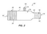
- FIG. 2is a schematic depicting an exemplary fluid bonding fitting of the present invention
- FIG. 3is a schematic depicting an exemplary assembly incorporating the fitting depicted in FIG. 2 ;
- FIG. 4is a schematic depicting an exemplary swimming pool system incorporating the assembly depicted in FIG. 3 .
- fluid bonding fittingwhich can be easily integrated into a variety of systems in which the bonding of a fluid would be useful.
- Exemplary systemsinclude, but are not limited to, for example, swimming pool systems, whirlpool systems, hot tub systems, sauna systems, and the like.
- the “fluid” as used herein and throughoutmay refer to either or both of a liquid and a gas.
- the fitting of present inventionis particularly useful in the bonding of water, particularly in the bonding of water circulating in a swimming pool system, and that, as such, a particularly exemplary application of the fitting is in its integration with a swimming pool system, the fitting is not to be limited to such an application, but rather, it's use and integration into and with a variety of systems as indicated above is fully contemplated and enabled by the present disclosure.
- the fittingis particularly advantageous in its integration into a swimming pool assembly and system as the fitting allows for the bonding of the swimming pool water such that the requirements of the above-stated newly implemented code regulation is met, i.e., so “that the pool water is in direct contact with an approved corrosion resistant conductive surface that exposes not less than 9 square inches of surface area to the pool water at all times.”
- the inventive fluid bonding fittingcomprises a main body having a protrusion extending from a top surface thereof.
- a collartapers inwardly from a proximal end of the main body and is coterminous with a first extension member.
- the fittingfurther comprises a second extension member, wherein such second extension member is coterminous with a distal end of the main body, and which may be tapered inwardly therefrom.
- the inventive fittingis integrated with a standard pool system, wherein such a system comprises a standard filter pump and a return hose.
- the first extension membermay engage the fitting to a water return hose
- the second extension membermay engage the fitting to a filter pump.
- a bond wirewhich electrically connects the various electrically conductive components of the system, is in electrical communication with the protrusion of the fitting, as well as, in electrical communication with a filter pump, the pool system's power supply source, and to a shell of the swimming pool.
- the conductive surface of the fittingexposes not less than up to about 18 square inches of surface area to the pool water.
- FIG. 1depicts a typical standard swimming pool system.
- an exemplary swimming pool system 10comprises a swimming pool 11 comprising a pool shell 12 , which holds water 14 .
- swimming pool 11further comprises a skimmer 13 , which draws water 14 from the pool surface.
- System 10also comprises a filter pump 16 , wherein filter pump 16 is connected to skimmer 13 via a skimmer hose 15 .
- a water return hose 17is connected to filter pump 16 and extends to swimming pool 11 to return the filtered water 14 to pool 11 .
- Filter pump 16comprises a plug 18 connected to an electrical outlet 20 .
- Electrical outlet 20in turn is in line with a service panelboard 22 .
- a bond wire 24which typically comprises an 8 American Wire Gauge (“AWG”) bonding conductor, extends to and from pool shell 12 , filter pump 16 , and electrical outlet 20 , and is connected to these various components via respective lugs 26 , 28 , and 30 .
- FIG. 1Further depicted in FIG. 1 is an electrically conductive ladder 32 , from and to which bond wire 24 also extends via a lug 34 , which is attached to ladder 32 .
- the inventive fluid bonding fitting of the present inventionserves to enhance the bonding of the system by bonding water 14 to the electrically conductive members of system 10 .
- an exemplary fluid bonding fittingshall be described with reference to FIG. 2 , wherein it is to be understood that the embodiment depicted in FIG. 2 is exemplary only, and that accordingly modifications and adaptations that would occur to one of ordinary skill in the art are contemplated herein.
- an exemplary fitting 50has a hollow interior 52 , which is defined by a generally cylindrically-shaped base 54 , an extension member 56 , and an extension member 58 .
- Base 54comprises a collar 60 on a proximal end thereof, wherein collar 60 tapers inwardly from the proximal end. Coterminous with collar 60 is extension member 56 .
- extension member 56An exterior surface of extension member 56 is characterized by a plurality of barbs 62 , wherein, as will be understood later herein, plurality of barbs 62 assists in the attachment of a water return hose 112 (see FIG. 4 ) to extension member 56 .
- Extension member 58is coterminous with a distal end of base 54 , and comprises a threaded exterior surface 64 , wherein threaded exterior surface 64 assists in securing fitting 50 to a filter pump 84 (see FIG. 3 ).
- Fitting 50further comprises a protrusion in the form of a stud butt 68 , which is disposed on a top surface 66 of base 54 , and preferably welded thereto. Attached to and disposed on stud butt 68 is a lug nut 70 , wherein, as will be explained in further detail below, lug nut 70 serves to connect a bond wire to fitting 50 .
- Fitting 50may be formed of a variety of materials provided that the material is suitably conductive to meet the functional requirements of the fitting. Nevertheless, an exemplary material comprises stainless steel.
- assembly 80comprises a water reservoir 82 in connection with a filter pump 84 , which comprises a pump 86 having a lug nut 90 on an exterior surface thereof.
- Filter pump 84further comprises a filter 88 in communication with pump 86 , wherein filter 88 comprises a receiving element 92 extending from a surface thereof.
- Assembly 80also includes fitting 50 as described above, wherein threaded exterior surface 64 of extension member 58 is engaged with receiving element 92 of filter 88 to secure fitting 50 to filter pump 84 .
- a pool system 100comprises assembly 80 , as described above, operably connected to a swimming pool 102 .
- the connection between assembly 80 and swimming pool 102may be achieved by connecting a skimmer hose 104 , which extends from a skimmer 106 of shell 108 of swimming pool 102 , to water reservoir 82 utilizing a clamp 110 .
- a proximal terminal end of water return hose 112is disposed over plurality of barbs 62 of extension member 56 , and clamped thereto via a clamp 116 .
- a distal terminal end 118 of water return hose 112is then connected to swimming pool 102 to return filtered water 103 to an interior 120 of swimming pool 102 .
- Pool system 100further comprises a power source 122 to which pump 86 is electrically connected via a plug 87 .
- system 100further comprises a lug nut 124 disposed on power source 122 and a lug nut 126 disposed on shell 108 of swimming pool 102 .
- the electrically conductive components of pool system 100e.g., power source 122 , fitting 50 , filter pump 84 , shell 108 , and water 103 , are bonded via the physical connection of a bond wire 128 to lug nut 70 of fitting 50 and to lug nuts 90 , 124 , and 126 .
- bond wire 128comprises an 8 AWG and comprises copper.
- System 100further comprises a grounded panelboard 130 to which the electrically conductive components of system 100 are bonded as discussed above.
Landscapes
- Engineering & Computer Science (AREA)
- Architecture (AREA)
- Water Supply & Treatment (AREA)
- Civil Engineering (AREA)
- Structural Engineering (AREA)
- Devices For Medical Bathing And Washing (AREA)
Abstract
Description
Claims (16)
Priority Applications (1)
| Application Number | Priority Date | Filing Date | Title |
|---|---|---|---|
| US12/182,516US8152538B1 (en) | 2008-07-30 | 2008-07-30 | Fluid bonding fitting and assembly and system incorporating the fitting, and method of use |
Applications Claiming Priority (1)
| Application Number | Priority Date | Filing Date | Title |
|---|---|---|---|
| US12/182,516US8152538B1 (en) | 2008-07-30 | 2008-07-30 | Fluid bonding fitting and assembly and system incorporating the fitting, and method of use |
Publications (1)
| Publication Number | Publication Date |
|---|---|
| US8152538B1true US8152538B1 (en) | 2012-04-10 |
Family
ID=45922020
Family Applications (1)
| Application Number | Title | Priority Date | Filing Date |
|---|---|---|---|
| US12/182,516Active - Reinstated2030-11-25US8152538B1 (en) | 2008-07-30 | 2008-07-30 | Fluid bonding fitting and assembly and system incorporating the fitting, and method of use |
Country Status (1)
| Country | Link |
|---|---|
| US (1) | US8152538B1 (en) |
Cited By (7)
| Publication number | Priority date | Publication date | Assignee | Title |
|---|---|---|---|---|
| US20130043194A1 (en)* | 2011-08-17 | 2013-02-21 | Buckman Laboratories International, Inc. | Tagged Polymers, Water Treatment Compositions, And Methods Of Their Use In Aqueous Systems |
| US20150053604A1 (en)* | 2013-08-23 | 2015-02-26 | Benjamin Lev Kweller | System and Method for Filtering a Metal Trough |
| US20150167335A1 (en)* | 2013-12-13 | 2015-06-18 | Asia Connection LLC | Water bonding fixture |
| US9194148B1 (en)* | 2012-11-13 | 2015-11-24 | Barrett Koller | Water bonding device and methods of use |
| US20160028183A1 (en)* | 2012-11-13 | 2016-01-28 | Barrett Koller | Water bonding device and methods of use |
| US20160169422A1 (en)* | 2014-10-30 | 2016-06-16 | Custom Molded Products, Inc. | Water-holding structure pump trap bond retrofit kit |
| US20230108937A1 (en)* | 2021-10-06 | 2023-04-06 | Luis Eduardo Perez | Pool debris collection container |
Citations (20)
| Publication number | Priority date | Publication date | Assignee | Title |
|---|---|---|---|---|
| US3420558A (en) | 1966-04-15 | 1969-01-07 | George R Whitten Jr | Mounting and grounding device for swimming pool equipment |
| US3783178A (en)* | 1972-08-03 | 1974-01-01 | Gen Signal Corp | Expansion joint for connecting rigid conduit with grounding continuity |
| US3967872A (en) | 1975-04-11 | 1976-07-06 | I-T-E Imperial Corporation | Cradle-type ground lug for conduit |
| US4106832A (en)* | 1977-04-19 | 1978-08-15 | John Joseph Vincent Burns | Electrical grounding clamp |
| JPS619137A (en) | 1984-06-22 | 1986-01-16 | Toshiba Corp | Underwater motor pump |
| US4763365A (en) | 1987-04-15 | 1988-08-16 | Tolo, Inc. | Spa system having high temperature safety device |
| US4781827A (en)* | 1987-01-02 | 1988-11-01 | Marlene L. Shields | Portable swimming pool skimmer |
| US4962285A (en) | 1988-11-04 | 1990-10-09 | Baker William H | Electrically groundable swimming pool deck anchor of plastic material |
| US5115862A (en) | 1990-08-08 | 1992-05-26 | Hastings Phillip J | Electrical grounding device for wells |
| US5222770A (en) | 1989-06-30 | 1993-06-29 | Rauma-Repola Oy | Connector for a hydraulic pressure hose |
| US5432688A (en) | 1993-03-12 | 1995-07-11 | H-Tech, Inc. | Plastic niche and grounding assembly therefor |
| US6021033A (en) | 1998-06-16 | 2000-02-01 | Charles E. Wade | Electrical shock prevention system |
| US6407469B1 (en) | 1999-11-30 | 2002-06-18 | Balboa Instruments, Inc. | Controller system for pool and/or spa |
| US6684588B1 (en) | 2002-05-22 | 2004-02-03 | Jesse Jones | Bonded swimming pool ladder anchor socket |
| US6710251B2 (en) | 2001-05-22 | 2004-03-23 | Electric Motion Company, Inc. | Fiber optic cable shield bond system |
| US6725524B2 (en)* | 2001-11-20 | 2004-04-27 | A. O. Smith Corporation | Electric motor bonding lug apparatus |
| US6776185B2 (en) | 2002-07-03 | 2004-08-17 | Delphi Technologies, Inc. | Grounded jet pump assembly for fuel system |
| US20050063843A1 (en) | 2003-09-18 | 2005-03-24 | Beckett Corporation | Submersible pump |
| JP2006200545A (en) | 1994-12-28 | 2006-08-03 | Denso Corp | In-tank type fuel pump arrangement |
| US7168416B2 (en) | 2005-03-23 | 2007-01-30 | Denso International America, Inc. | Multi-point grounding plate for fuel pump module |
- 2008
- 2008-07-30USUS12/182,516patent/US8152538B1/enactiveActive - Reinstated
Patent Citations (21)
| Publication number | Priority date | Publication date | Assignee | Title |
|---|---|---|---|---|
| US3420558A (en) | 1966-04-15 | 1969-01-07 | George R Whitten Jr | Mounting and grounding device for swimming pool equipment |
| US3783178A (en)* | 1972-08-03 | 1974-01-01 | Gen Signal Corp | Expansion joint for connecting rigid conduit with grounding continuity |
| US3967872A (en) | 1975-04-11 | 1976-07-06 | I-T-E Imperial Corporation | Cradle-type ground lug for conduit |
| US4106832A (en)* | 1977-04-19 | 1978-08-15 | John Joseph Vincent Burns | Electrical grounding clamp |
| JPS619137A (en) | 1984-06-22 | 1986-01-16 | Toshiba Corp | Underwater motor pump |
| US4781827A (en)* | 1987-01-02 | 1988-11-01 | Marlene L. Shields | Portable swimming pool skimmer |
| US4763365A (en) | 1987-04-15 | 1988-08-16 | Tolo, Inc. | Spa system having high temperature safety device |
| US4962285A (en) | 1988-11-04 | 1990-10-09 | Baker William H | Electrically groundable swimming pool deck anchor of plastic material |
| US5222770A (en) | 1989-06-30 | 1993-06-29 | Rauma-Repola Oy | Connector for a hydraulic pressure hose |
| US5115862A (en) | 1990-08-08 | 1992-05-26 | Hastings Phillip J | Electrical grounding device for wells |
| US5432688A (en) | 1993-03-12 | 1995-07-11 | H-Tech, Inc. | Plastic niche and grounding assembly therefor |
| JP2006200545A (en) | 1994-12-28 | 2006-08-03 | Denso Corp | In-tank type fuel pump arrangement |
| US6021033A (en) | 1998-06-16 | 2000-02-01 | Charles E. Wade | Electrical shock prevention system |
| US6407469B1 (en) | 1999-11-30 | 2002-06-18 | Balboa Instruments, Inc. | Controller system for pool and/or spa |
| US6643108B2 (en)* | 1999-11-30 | 2003-11-04 | Balboa Instruments, Inc. | Controller system for pool and/or spa |
| US6710251B2 (en) | 2001-05-22 | 2004-03-23 | Electric Motion Company, Inc. | Fiber optic cable shield bond system |
| US6725524B2 (en)* | 2001-11-20 | 2004-04-27 | A. O. Smith Corporation | Electric motor bonding lug apparatus |
| US6684588B1 (en) | 2002-05-22 | 2004-02-03 | Jesse Jones | Bonded swimming pool ladder anchor socket |
| US6776185B2 (en) | 2002-07-03 | 2004-08-17 | Delphi Technologies, Inc. | Grounded jet pump assembly for fuel system |
| US20050063843A1 (en) | 2003-09-18 | 2005-03-24 | Beckett Corporation | Submersible pump |
| US7168416B2 (en) | 2005-03-23 | 2007-01-30 | Denso International America, Inc. | Multi-point grounding plate for fuel pump module |
Cited By (12)
| Publication number | Priority date | Publication date | Assignee | Title |
|---|---|---|---|---|
| US20130043194A1 (en)* | 2011-08-17 | 2013-02-21 | Buckman Laboratories International, Inc. | Tagged Polymers, Water Treatment Compositions, And Methods Of Their Use In Aqueous Systems |
| US9347928B2 (en)* | 2011-08-17 | 2016-05-24 | Buckman Laboratories International, Inc. | Tagged polymers, water treatment compositions, and methods of their use in aqueous systems |
| US9194148B1 (en)* | 2012-11-13 | 2015-11-24 | Barrett Koller | Water bonding device and methods of use |
| US20160028183A1 (en)* | 2012-11-13 | 2016-01-28 | Barrett Koller | Water bonding device and methods of use |
| US9761990B2 (en)* | 2012-11-13 | 2017-09-12 | Barrett Koller | Water bonding device and methods of use |
| US20150053604A1 (en)* | 2013-08-23 | 2015-02-26 | Benjamin Lev Kweller | System and Method for Filtering a Metal Trough |
| US20150167335A1 (en)* | 2013-12-13 | 2015-06-18 | Asia Connection LLC | Water bonding fixture |
| US9431725B2 (en)* | 2013-12-13 | 2016-08-30 | Asia Connection LLC | Water bonding fixture |
| US20160322717A1 (en)* | 2013-12-13 | 2016-11-03 | Asia Connection LLC | Water bonding fixture |
| US9837733B2 (en)* | 2013-12-13 | 2017-12-05 | Asia Connection LLC | Water bonding fixture |
| US20160169422A1 (en)* | 2014-10-30 | 2016-06-16 | Custom Molded Products, Inc. | Water-holding structure pump trap bond retrofit kit |
| US20230108937A1 (en)* | 2021-10-06 | 2023-04-06 | Luis Eduardo Perez | Pool debris collection container |
Similar Documents
| Publication | Publication Date | Title |
|---|---|---|
| US8152538B1 (en) | Fluid bonding fitting and assembly and system incorporating the fitting, and method of use | |
| US11207513B2 (en) | Connection piece for producing a liquid connection between liquid-conveying lines, and medical appliance with such a connection piece | |
| KR200470445Y1 (en) | Connection structure of branch sleeves for power line | |
| US9255656B2 (en) | Fitting for a heat pump and method of installation | |
| US7488415B2 (en) | Disposable salt chlorine generator | |
| US9837733B2 (en) | Water bonding fixture | |
| US9759364B2 (en) | Armored hose assembly | |
| KR101597355B1 (en) | Conductive high sensitivity earth electrode | |
| US9592178B1 (en) | System for repelling mosquitoes near a spa | |
| CA2299834A1 (en) | Fluid conducting connector assembly | |
| US6766573B2 (en) | Electric motor bonding apparatus | |
| KR100910626B1 (en) | Electromagnetic Field Water Treatment Equipment | |
| JP4473767B2 (en) | Spray electrolytic polishing decontamination equipment | |
| KR100659024B1 (en) | Branch sleeve for connecting low voltage wire | |
| CN205759347U (en) | Protection against electric shock fire plant | |
| KR102672680B1 (en) | Safety-improved underground distribution line fixing device with fire suppression function | |
| US2831911A (en) | Welder cable terminal | |
| CN109357092B (en) | A joint for gas and electric pipeline | |
| US20160169422A1 (en) | Water-holding structure pump trap bond retrofit kit | |
| CN209948363U (en) | Low-voltage switchgear casing with enhanced function | |
| CN209200650U (en) | A kind of earth leakage protective device | |
| CN207021026U (en) | Double terminal plate straight joint water-cooled cables | |
| CN206194519U (en) | Dry -type metallic glass transformer core ground outlet structure | |
| CN208522463U (en) | A kind of low capacitor transient stage voltage suppressor device of single channel | |
| KR101455041B1 (en) | Electric heat pipe assembly |
Legal Events
| Date | Code | Title | Description |
|---|---|---|---|
| STCF | Information on status: patent grant | Free format text:PATENTED CASE | |
| FEPP | Fee payment procedure | Free format text:PATENT HOLDER CLAIMS MICRO ENTITY STATUS, ENTITY STATUS SET TO MICRO (ORIGINAL EVENT CODE: STOM); ENTITY STATUS OF PATENT OWNER: MICROENTITY | |
| FPAY | Fee payment | Year of fee payment:4 | |
| MAFP | Maintenance fee payment | Free format text:PAYMENT OF MAINTENANCE FEE, 8TH YEAR, MICRO ENTITY (ORIGINAL EVENT CODE: M3552); ENTITY STATUS OF PATENT OWNER: MICROENTITY Year of fee payment:8 | |
| FEPP | Fee payment procedure | Free format text:MAINTENANCE FEE REMINDER MAILED (ORIGINAL EVENT CODE: REM.); ENTITY STATUS OF PATENT OWNER: MICROENTITY | |
| PRDP | Patent reinstated due to the acceptance of a late maintenance fee | Effective date:20240422 | |
| FEPP | Fee payment procedure | Free format text:PETITION RELATED TO MAINTENANCE FEES FILED (ORIGINAL EVENT CODE: PMFP); ENTITY STATUS OF PATENT OWNER: MICROENTITY Free format text:PETITION RELATED TO MAINTENANCE FEES GRANTED (ORIGINAL EVENT CODE: PMFG); ENTITY STATUS OF PATENT OWNER: MICROENTITY Free format text:SURCHARGE, PETITION TO ACCEPT PYMT AFTER EXP, UNINTENTIONAL (ORIGINAL EVENT CODE: M3558); ENTITY STATUS OF PATENT OWNER: MICROENTITY | |
| MAFP | Maintenance fee payment | Free format text:PAYMENT OF MAINTENANCE FEE, 12TH YEAR, MICRO ENTITY (ORIGINAL EVENT CODE: M3553); ENTITY STATUS OF PATENT OWNER: MICROENTITY Year of fee payment:12 |