US8152339B2 - Illumination device - Google Patents
Illumination deviceDownload PDFInfo
- Publication number
- US8152339B2 US8152339B2US12/597,648US59764808AUS8152339B2US 8152339 B2US8152339 B2US 8152339B2US 59764808 AUS59764808 AUS 59764808AUS 8152339 B2US8152339 B2US 8152339B2
- Authority
- US
- United States
- Prior art keywords
- light
- slab
- optical
- projecting
- curve
- Prior art date
- Legal status (The legal status is an assumption and is not a legal conclusion. Google has not performed a legal analysis and makes no representation as to the accuracy of the status listed.)
- Active
Links
Images


Classifications
- H—ELECTRICITY
- H10—SEMICONDUCTOR DEVICES; ELECTRIC SOLID-STATE DEVICES NOT OTHERWISE PROVIDED FOR
- H10F—INORGANIC SEMICONDUCTOR DEVICES SENSITIVE TO INFRARED RADIATION, LIGHT, ELECTROMAGNETIC RADIATION OF SHORTER WAVELENGTH OR CORPUSCULAR RADIATION
- H10F77/00—Constructional details of devices covered by this subclass
- H10F77/40—Optical elements or arrangements
- H10F77/42—Optical elements or arrangements directly associated or integrated with photovoltaic cells, e.g. light-reflecting means or light-concentrating means
- G—PHYSICS
- G02—OPTICS
- G02B—OPTICAL ELEMENTS, SYSTEMS OR APPARATUS
- G02B19/00—Condensers, e.g. light collectors or similar non-imaging optics
- G02B19/0004—Condensers, e.g. light collectors or similar non-imaging optics characterised by the optical means employed
- F—MECHANICAL ENGINEERING; LIGHTING; HEATING; WEAPONS; BLASTING
- F21—LIGHTING
- F21S—NON-PORTABLE LIGHTING DEVICES; SYSTEMS THEREOF; VEHICLE LIGHTING DEVICES SPECIALLY ADAPTED FOR VEHICLE EXTERIORS
- F21S11/00—Non-electric lighting devices or systems using daylight
- G—PHYSICS
- G02—OPTICS
- G02B—OPTICAL ELEMENTS, SYSTEMS OR APPARATUS
- G02B19/00—Condensers, e.g. light collectors or similar non-imaging optics
- G02B19/0004—Condensers, e.g. light collectors or similar non-imaging optics characterised by the optical means employed
- G02B19/0019—Condensers, e.g. light collectors or similar non-imaging optics characterised by the optical means employed having reflective surfaces only (e.g. louvre systems, systems with multiple planar reflectors)
- G—PHYSICS
- G02—OPTICS
- G02B—OPTICAL ELEMENTS, SYSTEMS OR APPARATUS
- G02B19/00—Condensers, e.g. light collectors or similar non-imaging optics
- G02B19/0004—Condensers, e.g. light collectors or similar non-imaging optics characterised by the optical means employed
- G02B19/0028—Condensers, e.g. light collectors or similar non-imaging optics characterised by the optical means employed refractive and reflective surfaces, e.g. non-imaging catadioptric systems
- H—ELECTRICITY
- H10—SEMICONDUCTOR DEVICES; ELECTRIC SOLID-STATE DEVICES NOT OTHERWISE PROVIDED FOR
- H10F—INORGANIC SEMICONDUCTOR DEVICES SENSITIVE TO INFRARED RADIATION, LIGHT, ELECTROMAGNETIC RADIATION OF SHORTER WAVELENGTH OR CORPUSCULAR RADIATION
- H10F77/00—Constructional details of devices covered by this subclass
- H10F77/40—Optical elements or arrangements
- H10F77/413—Optical elements or arrangements directly associated or integrated with the devices, e.g. back reflectors
- H—ELECTRICITY
- H10—SEMICONDUCTOR DEVICES; ELECTRIC SOLID-STATE DEVICES NOT OTHERWISE PROVIDED FOR
- H10F—INORGANIC SEMICONDUCTOR DEVICES SENSITIVE TO INFRARED RADIATION, LIGHT, ELECTROMAGNETIC RADIATION OF SHORTER WAVELENGTH OR CORPUSCULAR RADIATION
- H10F77/00—Constructional details of devices covered by this subclass
- H10F77/40—Optical elements or arrangements
- H10F77/42—Optical elements or arrangements directly associated or integrated with photovoltaic cells, e.g. light-reflecting means or light-concentrating means
- H10F77/488—Reflecting light-concentrating means, e.g. parabolic mirrors or concentrators using total internal reflection
- G—PHYSICS
- G02—OPTICS
- G02B—OPTICAL ELEMENTS, SYSTEMS OR APPARATUS
- G02B6/00—Light guides; Structural details of arrangements comprising light guides and other optical elements, e.g. couplings
- G02B6/0001—Light guides; Structural details of arrangements comprising light guides and other optical elements, e.g. couplings specially adapted for lighting devices or systems
- G02B6/0011—Light guides; Structural details of arrangements comprising light guides and other optical elements, e.g. couplings specially adapted for lighting devices or systems the light guides being planar or of plate-like form
- G02B6/0033—Means for improving the coupling-out of light from the light guide
- G02B6/0035—Means for improving the coupling-out of light from the light guide provided on the surface of the light guide or in the bulk of it
- G02B6/0038—Linear indentations or grooves, e.g. arc-shaped grooves or meandering grooves, extending over the full length or width of the light guide
- G—PHYSICS
- G02—OPTICS
- G02B—OPTICAL ELEMENTS, SYSTEMS OR APPARATUS
- G02B6/00—Light guides; Structural details of arrangements comprising light guides and other optical elements, e.g. couplings
- G02B6/0001—Light guides; Structural details of arrangements comprising light guides and other optical elements, e.g. couplings specially adapted for lighting devices or systems
- G02B6/0011—Light guides; Structural details of arrangements comprising light guides and other optical elements, e.g. couplings specially adapted for lighting devices or systems the light guides being planar or of plate-like form
- G02B6/0075—Arrangements of multiple light guides
- G02B6/0078—Side-by-side arrangements, e.g. for large area displays
- Y—GENERAL TAGGING OF NEW TECHNOLOGICAL DEVELOPMENTS; GENERAL TAGGING OF CROSS-SECTIONAL TECHNOLOGIES SPANNING OVER SEVERAL SECTIONS OF THE IPC; TECHNICAL SUBJECTS COVERED BY FORMER USPC CROSS-REFERENCE ART COLLECTIONS [XRACs] AND DIGESTS
- Y02—TECHNOLOGIES OR APPLICATIONS FOR MITIGATION OR ADAPTATION AGAINST CLIMATE CHANGE
- Y02E—REDUCTION OF GREENHOUSE GAS [GHG] EMISSIONS, RELATED TO ENERGY GENERATION, TRANSMISSION OR DISTRIBUTION
- Y02E10/00—Energy generation through renewable energy sources
- Y02E10/50—Photovoltaic [PV] energy
- Y02E10/52—PV systems with concentrators
- Y—GENERAL TAGGING OF NEW TECHNOLOGICAL DEVELOPMENTS; GENERAL TAGGING OF CROSS-SECTIONAL TECHNOLOGIES SPANNING OVER SEVERAL SECTIONS OF THE IPC; TECHNICAL SUBJECTS COVERED BY FORMER USPC CROSS-REFERENCE ART COLLECTIONS [XRACs] AND DIGESTS
- Y10—TECHNICAL SUBJECTS COVERED BY FORMER USPC
- Y10T—TECHNICAL SUBJECTS COVERED BY FORMER US CLASSIFICATION
- Y10T29/00—Metal working
- Y10T29/49—Method of mechanical manufacture
- Y10T29/49826—Assembling or joining
Definitions
- the present inventionrelates generally to collimating optics. More particularly, the present invention relates to light-guiding collimator optics for luminaires.
- Luminairesthat collimate light from an isotropic source to form a beam of light are known.
- the optical elements of the luminairescan be either lenses or mirrors, and the isotropic light source can be an incandescent bulb, a fluorescent bulb, or a light emitting diode. Light is emitted from the bulb in all directions and interacts with the optical elements, and is redirected to make a beam in which all the rays of light are substantially parallel.
- automotive headlampsOne widespread application for such luminaires is automotive headlamps.
- a bulbIn a typical automotive headlamp, a bulb is positioned at the focal point of a parabolic reflector. Light emanates from the bulb in all directions and strikes the parabolic reflector, which collimates the light into a beam.
- these automotive headlampshave considerable depth, occupying space in the car.
- Other exemplary applicationsinclude products such as, amongst others, stage lighting, flashlights, medical lighting and dentistry lighting.
- Parabolic reflectorcan also be upwards of 20 cm deep for an automotive headlamp and a cover is also required to protect the bulb and reflector cavity.
- automotive headlampsare generally made by injection molding poly(methyl-methacrylate) (PMMA) or poly carbonate, the clear polymers must be coated in a reflective mirror coating in order to operate correctly.
- PMMApoly(methyl-methacrylate)
- poly carbonatethe clear polymers must be coated in a reflective mirror coating in order to operate correctly.
- the polymers used to make these assembliesare recyclable with a high recovery value, but the mirror coating complicates the recycling process and reduces the recovery value.
- the present inventionprovides an illumination device that comprises a light-projecting stage having at least one optical input aperture, an output surface, and optical elements formed between the at least one optical input aperture and the output surface.
- the devicefurther comprises an optical waveguide stage optically coupled to the at least one optical input aperture, the optical waveguide stage having an input surface to receive light and a waveguide section to guide the light from the input surface to the at least one optical input aperture, the optical elements directing the light from the at least one input aperture to the output surface wherefrom the light exits as a beam.
- the present inventionprovides an illumination device that comprises a first light-projecting stage having a first at least one optical input aperture, a first output surface, and first optical elements formed between the first at least one optical input aperture and the first output surface.
- the devicealso comprises a second light-projecting stage having a second at least one optical input aperture, a second output surface, and second optical elements formed between the second at least one optical input aperture and the second output surface.
- the devicefurther comprises an optical waveguide stage optically coupled to the first at least one optical input aperture and to the second at least one optical input aperture, the optical waveguide stage having a first input surface to receive a first light from a first light source and a second input surface to receive a second light from a second light source.
- the optical waveguidefurther has a waveguide section to guide the first light from the first input surface to the first at least one optical input aperture, the first optical elements directing the first light from the first at least one input aperture to the first output surface wherefrom the first light exits as a first beam.
- the waveguide sectionalso to guide the second light from the second input surface to the first at least one optical input aperture and to the second at least one optical input aperture, the first optical elements and the second optical elements directing the second light respectively from the first at least one input aperture to the first output surface and from the second at least one input aperture to the second output surface, the second light exiting form the first and second output surface forming a second beam.
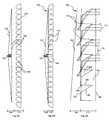
- FIG. 1shows a first embodiment of the light-guide collimating optic of the present invention
- FIG. 2shows an enlarged view of the embodiment of FIG. 1 with light rays entering the collimating stage
- FIG. 3shows the embodiment of FIG. 1 with an isotropic light source at the center of the optic
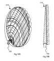
- FIG. 4shows a perspective view of the revolved geometry embodiment of the light-guide collimating optic of the present invention
- FIG. 5Ashows the embodiment of FIG. 3 with light rays exiting the emitter face
- FIG. 5Bshows a perspective view of the embodiment of FIG. 4 in a housing
- FIG. 5Cshows a simple parabolic reflector spot lamp
- FIG. 5Dshows a perspective view of a spot lamp
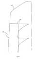
- FIG. 6Ashows an exploded view of a slab design embodiment of FIG. 3 ;
- FIG. 6Bshows an intact view of a slab design embodiment of FIG. 3 ;
- FIG. 6Cshows an enlarged view of a slab design embodiment of FIG. 3 ;
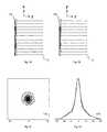
- FIG. 7Ashows a computer simulation in the XZ plane of the embodiment of FIG. 3 ;
- FIG. 7Bshows a computer simulation in the YZ plane of the embodiment of FIG. 3 ;
- FIG. 7Cshows the intensity relief plot from a computer simulation of the embodiment of FIG. 3 ;
- FIG. 7Dshows the intensity profile from a computer simulation of the embodiment of FIG. 3 ;
- FIG. 8shows an embodiment of the light-guide collimating optic of the present invention where light rays undergo one or two reflections in the collimating stage
- FIG. 9shows an embodiment of the light-guide collimating optic of the present invention where parabolic reflectors are oriented to directed light downwards in the collimating stage;
- FIG. 10shows an embodiment of the light-guide collimating optic of the present invention where parabolic reflectors are oriented to direct light upwards in the collimating stage;
- FIG. 11Ashows an embodiment of the light-guide collimating optic of the present invention where small functional elements are implemented
- FIG. 11Bshows an enlarged view of the embodiment of FIG. 11A ;
- FIG. 12Ashows a perspective view of the linear geometry embodiment of the light-guide collimating optic of the present invention where the slab design of FIG. 6 and a tube-shaped light source are implemented;
- FIG. 12Bshows a cross-sectional view of the embodiment of FIG. 12A ;
- FIG. 13Ashows a perspective view of the revolved geometry embodiment of the light-guide collimating optic of the present invention where the slab design of FIG. 6 and the small functional elements of FIG. 11 are implemented;
- FIG. 13Bshows a complete cross-sectional view of the embodiment of FIG. 13A ;
- FIG. 13Cshows an enlarged cross-sectional view of the embodiment of FIG. 13A ;
- FIG. 14Ashows a perspective view of the broad beam embodiment of the light-guide collimating optic of the present invention where a linear geometry describes the functional elements, a revolved geometry describes the waveguide stage, and the slab design of FIG. 6 is implemented;
- FIG. 14Bshows a complete cross-sectional view of the embodiment of FIG. 14A ;
- FIG. 14Cshows an enlarged cross-sectional view of the of the embodiment of FIG. 14A ;
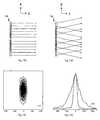
- FIG. 15Ashows a computer simulation of the embodiment of FIG. 14 in the XZ plane
- FIG. 15Bshows a computer simulation of the embodiment of FIG. 14 in the YZ plane
- FIG. 15Cshows the intensity relief plot from a computer simulation of the embodiment of FIG. 14 ;
- FIG. 15Dshows the intensity profile from a computer simulation of the embodiment of FIG. 14 ;
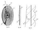
- FIG. 16Ashows a perspective view of the semi-broad beam embodiment of the light-guide collimating optic of the present invention where the circular arcs describing the duality of revolved optics are not concentric with the circumference of the light-guide collimating optic and the slab design of FIG. 6 is implemented;
- FIG. 16Bshows a complete cross-sectional view of the embodiment of FIG. 16A ;
- FIG. 16Cshows an enlarged cross-sectional view of the embodiment of FIG. 16A ;
- FIG. 17Ashows a perspective view of the embodiment of FIG. 16 with cylindrical lenses on the emitter face
- FIG. 17Bshows a complete cross-sectional view of the embodiment of FIG. 17A ;
- FIG. 17Cshows an enlarged cross-sectional view of the embodiment of FIG. 17A ;
- FIG. 18Ashows a perspective view of an embodiment of the light-guide collimating optic of the present invention where the optic consists of a circular section of the embodiment of FIG. 16 and the isotropic light source is edge-mounted;
- FIG. 18Bshows a complete cross-sectional view of the embodiment of FIG. 18A ;
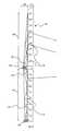
- FIG. 19shows an embodiment of the light-guide collimating optic of the present invention where compound reflectors are used in the collimating stage and the slab design of FIG. 6 is implemented;
- FIG. 20shows an embodiment of the light-guide collimating optic of the present invention where the collimating stage containing a large reflector overlaps the waveguide stage and the slab design of FIG. 6 is implemented;
- FIG. 21shows an embodiment of the light-guide collimating optic of the present invention where high beam and low beam functionality and angular reflectors of FIG. 9 in the collimating stage are incorporated;
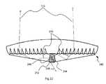
- FIG. 22shows an embodiment of the light-guide collimating optic of the present invention where dichroic mirrors encase the isotropic light source.
- the present inventionis a luminaire that uses a light-guide collimating optic (LGCO), which can also be referred to as an illumination device.
- LGCOaccepts light from a small isotropic light source such as a light emitting diode (LED) or a bulb and spreads the light over a wide area while also collimating it to form a beam wherein all the rays are substantially parallel.
- the LGCOincludes of a thin slab of optically transmissive material with an emitter face, out of which light emerges collimated, and a smaller input face, located on the edge of the LGCO. There can be more than one input face on an LGCO.
- the LGCOhas two stages, a waveguide stage (also referred to as an optical waveguide stage and which includes a waveguide section) and a collimating stage (also referred to as a light-projecting stage).
- a waveguide stagealso referred to as an optical waveguide stage and which includes a waveguide section
- a collimating stagealso referred to as a light-projecting stage.
- Light inserted into the LGCO at an input faceis guided internally by total internal reflection in the waveguide stage and spreads substantially evenly over the LGCO.
- Lightcouples into the collimating stage via a multiplicity of apertures (also referred to as optical input apertures) that allow light to escape the waveguide stage.
- the LGCOcan be cut circularly, squarely, or in any other shape.
- the light beamemerges substantially collimated.
- the light beamcan also be shaped in a variety of ways, and made to diverge to any desired degree in one plane or in two planes.
- LGCOsuch that it accepts light from two sources so that the emerging light differs with each source.
- FIG. 1shows the first embodiment of the LGCO 100 .
- Lightis emitted from an isotropic light source 102 placed at the edge 104 (also referred to as an input surface) of the LGCO 100 and emerges from an emitter face 106 (also referred to as an output surface) collimated.
- the LGCO 100has a waveguide stage 108 into which light 110 from the isotropic source 102 is first inserted and guided. It also has a collimating stage 114 that shapes and directs the final beam 112 .
- the waveguide stage 108 and the collimating stagecan be made of any appropriate optical material 116 (e.g., PMMA).
- the waveguide stage 108has one face 118 (also referred to as a first surface) on its back and a multiplicity of interfaces 120 on its front side.
- the face 118is an interface between the optical material 116 and the exterior material 122 .
- the exterior material 122can be a gas or another material of lower index of refraction than the optical material 116 .
- the multiplicity of interfaces 120separate the optical material 116 from another material or gas of lower index of refraction 124 .
- the interface 118makes a reflector 126 that operates on the light 110 by total internal reflection.
- the multiplicity of interfaces 120also makes reflectors 128 that operate on the light 110 by total internal reflection.
- the backside reflector 126 and the multiplicity of front side reflectors 128can be substantially parallel.
- FIG. 2shows three rays 110 at different angles exiting the waveguide stage 108 via the aperture 130 and entering the collimating stage 114 .
- the rays 110reach an interface 134 , which has a parabolic shape.
- the interface 134separates the optical material 136 comprising the collimating stage 114 from the gas or lower index of refraction material 124 .
- the interface 134thus creates a reflector 138 that operates by total internal reflection—although this reflector 138 can also have a mirrored surface.
- the light rays 110 impinging on the reflector 138can be collimated (made parallel) and immediately exit the LGCO 100 out the emitter face 106 .
- the reflector 138is a parabolic section.
- this reflectorcan also be a round section, or any other appropriate shape or a circular approximation of the optimal parabolic section.
- the parabola 140 which describes the reflector 138has a focal point 142 which is coincident with the aperture 130 , and the axis of the parabola 144 points in the output direction of the beam—in this case, normal to the emitter face 106 of the LGCO 100 .
- Light 110 entering the collimating stage 114 from the aperture 130can be thought of as diverging from the focus 142 of the parabola 140 because the focus 142 of the parabola 140 and the aperture 130 are coincident, and the aperture 130 is narrow.
- a parabolic reflector 138collimates light 110 that is diverging from its focus 142 in a direction parallel to the axis 144 of the parabola 140 .
- the LGCO 100can be used with a bulb 102 on one edge as shown previously or with the bulb 102 in the center of the LGCO 100 . This is shown in FIG. 3 .
- the cross-section from FIGS. 1-3can be made into a linear optic in which case light 110 would be inserted along the whole edge of the optic 104 (an example is shown in FIG. 12 ).
- FIG. 4shows a revolved LGCO 100 that is shaped like a discus 146 .
- the cross-section 148is shown stippled in the figure, and is the same as FIG. 1 .
- the discus 146has a hub 150 in its center that can accept a bulb.
- Light 110enters the discus 146 via a circular wall 152 of the hub 150 .
- Light 110then propagates as before and exits as a collimated beam 112 out the emitter face 106 .
- FIG. 5shows a comparison between the LGCO 100 and a simple parabolic reflector 154 . Both optics produce a collimated beam 112 , but the LGCO 100 is considerably more compact along the optical axis 156 of the collimated light 112 .
- FIG. 5Bexemplifies this compactness using the example of a spot-lamp 158 and a LGCO in a housing 160 of the same diameter.
- LGCO 100it could be difficult to manufacture the LGCO 100 in one piece as shown in FIGS. 1-4 .
- An easier process to mold the LGCO 100 by injection molding, compression molding, or another suitable meansis to split the LGCO 100 into two slabs which each have no undercuts and which fit together. These parts can be dry-fitted together and require no welding or optical bonding.
- the divisionis shown in FIG. 6 , with the waveguide stage 108 comprising one slab 162 and the collimating stage 114 comprising another slab 164 .
- the waveguide stage 108has exit faces 166 through which light 110 can escape, and it is coupled into the collimating stage 114 through an injection face 168 abutting the exit face 166 .
- the exit faces 166 and injection faces 168make apertures 130 between the waveguide stage 108 and the collimating stage 114 .
- FIG. 6shows light 110 striking the reflectors 138 after exiting the apertures 130 and making collimated beams 112 .
- the beams 112 emerging from the reflectors 138 in the collimating stage slab 164do not cover the whole emitter face 106 .
- FIG. 7shows these results.
- a 20 cm diameter revolved LGCO 100was modeled and the profile 174 of the light beam analyzed at a distance of 1 meter from the optic 100 ; dimensions on the figure are in centimeters and the intensity of the beam is on an arbitrary scale.
- the beamis roughly Gaussian.
- the simulationwas done with a finite number of rays and accounts for the noise in the profiles 174 and relief plot 176 .
- FIG. 8shows rays 178 and 180 exiting the waveguide stage 108 at the apertures 130 .
- Rays exiting the waveguide stage 108 and entering the collimating stage 114can go through one of two processes, both of which are described here.
- Ray 178 enters the collimating stage 114immediately strikes the reflector 138 , and then exits the LGCO 100 .
- the face 182is parallel to the backside face 118 of the waveguide stage 108 .
- the face 182is an interface between the optical material 136 and the gas or lower index of refraction material 124 between the collimating stage 114 and the wave-guide stage 108 (not visible in FIG. 8 but shown clearly at FIG. 6C ).
- This interface 182makes a reflector 184 operating under total internal reflection.
- FIG. 8also shows the parabola 140 that prescribes the reflectors 138 in the collimating stage 114 .
- This parabola 140has its focus 142 coincident with the center of the apertures 130 that link the waveguide stage 108 and the collimating stage 114 , and the axis 144 of the parabola 140 points in the direction of the beam 112 .
- FIG. 9shows how one can control the direction of the collimated beam by altering the parabola 140 , which is used to prescribe the reflectors 138 .
- the axis 144 of the parabola 140has been angled downward. If this is done while maintaining the focus 142 of the parabola 140 coincident with the center of the apertures 130 then the resultant beam 112 will be collimated and angled downwards.
- FIG. 10shows a similar embodiment as FIG. 9 except that the axis 144 of the parabola 140 has been angled upwards and the corresponding beam 112 will also be collimated and angled upward.
- a circular reflector in the collimating stagecan be used to approximate the parabolic reflector and can produce substantially collimated light. They could also be potentially easier to build. It may also be the case for certain applications that increased divergence is desirable, and this can be achieved by chosing another shape for the reflector, such as, for example, a section of a circle.
- FIG. 11shows a LGCO 100 with smaller functional elements 186 .
- the functional elements 186are defined as: the reflectors 138 , the interfaces 120 , and the apertures 130 comprised of the exit faces 166 and the injection faces 168 .
- the optics that have been shown in the preceding figureshave used large functional elements 186 for explanatory purposes. In actuality, the functional elements 186 would likely be small, with a period 188 between 1 micron and 1 millimeter. Below 1 micron, optical interference would likely dominate the performance of the optic 100 , and above 1 millimeter in size the necessary diamond tooling becomes prohibitively expensive. However, larger sizes are possible and functional, and smaller sizes would also function at wavelengths below those of visible light.
- FIGS. 12A and 12Bshow a linear LGCO 190 made using a two-part slab composition with one slab 162 for the waveguide stage 108 and another slab 164 for the collimating stage 114 .
- a tube shaped bulb 192in this case a fluorescent bulb, runs down one edge of the optic.
- the light emerging from the linear LGCO 190will be collimated in the plane YZ and divergent in the plane XZ.
- This embodimenthas applications in computer displays and lighting.
- FIGS. 13A-13Cshow a revolved LGCO 194 .
- This opticwill produce a beam like the one from FIG. 7 .
- the diameter of this LGCO 194is 20 centimeters and the LGCO 194 is approximately 1 centimeter thick at its widest point.
- the hub 150has room for an LED bulb 5 mm in diameter and 7 mm tall, other bulb sizes can be accommodated by altering the design.
- FIG. 14A-14Cshows a hybrid linear/revolved optic 198 , defined here as a broadbeam optic.
- the functional elements 186 from FIG. 11describe the cross section of the linear optic along a longitudinal axis 200 .
- the backside face 118 of the waveguide stage 108is revolved and a hub 150 for a bulb is in the center of the LGCO 198 .
- This LGCO 198is not as efficient as the previous optic 194 in that more light is lost due to internal scattering.
- the LGCO 198collimates light in the plane YZ while letting the light fan out in the plane XZ. This would be useful for automotive headlamps where one would want to illuminate a wide-swath of road but where illumination above the road is not essential.
- the LGCO 198produces a similar beam as the LGCO 190 from FIGS. 12A-12C , except that it accepts a small point source bulb and does not require a long tubular bulb.
- Profiles 210 and a relief plot 212 of this broadbeam LGCO 198are shown in FIGS. 15A-15D .
- FIGS. 16A-16CShown in FIGS. 16A-16C is another LGCO 202 , called a semi-broadbeam optic.
- the functional elements 186are prescribed on circular arcs 204 and 206 .
- the circular arcsare not concentric with the circumference 208 of the LGCO 202 .
- the centers of the circles that prescribe the arcs 204 and 206are equidistant from the center of the LGCO 202 itself.
- the resultant beam from the LGCO 202looks very similar too that shown in FIGS. 15A-15D , but it is optically more efficient than the embodiment 198 from FIG. 14 .
- FIG. 17shows the revolved LGCO 194 with cylindrical lenses 214 on the emitter face 106 .
- the resultant LGCO 216also produces a broadbeam, which is divergent YZ plane and collimated in the XZ plane.
- FIGS. 18A-18Bshow another embodiment of the optic where this is the case.
- the bulb 102is positioned at the edge of the LOCO 218 .
- the LGCO 218is formed by taking a circular section of the LGCO 216 from FIG. 17A-17C . Such sectioning can be done to make any embodiment edge-lit; furthermore, the sectioning need not be circular but can be square, triangular, or any appropriate shape.
- the reflector 138 in the collimating stage 114any other sort of reflector, including a compound reflector 220 as is shown in FIG. 19 . This gives more light-shaping freedom.
- the waveguide stage slab 162is shown in preceding figures as tapering to a very fine edge. For structural and fabrication reasons, the waveguide stage slab 162 may require a minimum thickness.
- FIG. 20shows a wider and larger reflector 222 that can overlap the outside edge 224 of the waveguide stage slab 162 .
- FIG. 21shows a sectional design for a highbeam/lowbeam LGCO 226 .
- the LOCO 226accepts light from a central bulb 228 and an edge-mounted bulb 230 .
- the reflectors 138 in the top half 236 of the optic 226are modeled after FIG. 9 ; they will collimate light into a downwards pointing beam.
- the reflectors 138 on the bottom half 238 of the LGCO 226will collimate light horizontally.
- the central bulb 228emits light 232 this light travels in both directions within the waveguide stage 108 .
- This lightcouples to reflectors 138 in both the top half 236 and the bottom half 238 of the LGCO 226 .
- the light 232 emitted from the LGCO 226is comprised of rays aimed downwards coming from the top half 236 and rays traveling horizontally coming from the bottom half 238 .
- the edge-mounted bulb 230emits light 234 this light enters the waveguide stage 108 at the bottom edge 240 and travels in the waveguide stage 108 going upwards only.
- Light 234will bypass all the apertures 130 and remain in the waveguide stage 108 through the bottom half 238 of the LGCO 226 . This is because the apertures 130 allow light to exit the waveguide stage 108 only when that light is traveling in the direction in which the waveguide stage 108 is tapering. When light travels the opposite direction in the waveguide stage 108 , it cannot exit at the apertures 130 and continues to propagate.
- the LGCO 226In the case of the LGCO 226 , the light 234 from the edge-mounted bulb 230 will propagate through the bottom half 238 and into the top half 236 of the waveguide stage 108 . The light 234 will then be traveling in the correct sense so as to pass through the apertures 130 and reflect off the reflectors 138 . Because the reflectors 138 in the top half 236 of the optic 226 are oriented so as to aim light downwards, the resulting beam 234 will be directed downwards. Thus, the LGCO 226 creates a low-beam when only the edge-mounted bulb 230 is lit and a high-beam when the central bulb 228 is lit.
- FIG. 22shows an exemplary embodiment of such a LGCO 242 using a high-heat bulb 244 .
- This figureshows other innovations specific to such a light source.
- a dichroic mirror 246which reflects infrared radiation 248 is used to separate the lamp 244 from the LGCO 242 . This reflects infrared radiation 248 back towards the lamp 244 while allowing visible light 250 to enter into the LGCO 242 and to be shaped into a forward collimated beam 112 .
- a second dichroic mirror 252 that reflects visible 250 lightcan be placed underneath the light source 244 to allow infrared radiation 248 to escape out of the light-bulb housing 254 while trapping visible light 250 inside so that it can couple into the LGCO 242 .
- lightcan be coupled into any of the above light-guide collimating optics via a fiber optic.
Landscapes
- Physics & Mathematics (AREA)
- General Physics & Mathematics (AREA)
- Optics & Photonics (AREA)
- Life Sciences & Earth Sciences (AREA)
- Sustainable Development (AREA)
- Engineering & Computer Science (AREA)
- General Engineering & Computer Science (AREA)
- Photovoltaic Devices (AREA)
- Optical Elements Other Than Lenses (AREA)
- Optical Couplings Of Light Guides (AREA)
- Planar Illumination Modules (AREA)
- Non-Portable Lighting Devices Or Systems Thereof (AREA)
Abstract
Description
Claims (20)
Priority Applications (2)
| Application Number | Priority Date | Filing Date | Title |
|---|---|---|---|
| US12/597,648US8152339B2 (en) | 2007-05-01 | 2008-05-01 | Illumination device |
| US13/028,976US20110310633A1 (en) | 2007-05-01 | 2011-02-16 | Illumination device |
Applications Claiming Priority (5)
| Application Number | Priority Date | Filing Date | Title |
|---|---|---|---|
| US91520707P | 2007-05-01 | 2007-05-01 | |
| US94274507P | 2007-06-08 | 2007-06-08 | |
| US95177507P | 2007-07-25 | 2007-07-25 | |
| PCT/CA2008/000847WO2008131566A1 (en) | 2007-05-01 | 2008-05-01 | Illumination device |
| US12/597,648US8152339B2 (en) | 2007-05-01 | 2008-05-01 | Illumination device |
Publications (2)
| Publication Number | Publication Date |
|---|---|
| US20100202142A1 US20100202142A1 (en) | 2010-08-12 |
| US8152339B2true US8152339B2 (en) | 2012-04-10 |
Family
ID=39925147
Family Applications (6)
| Application Number | Title | Priority Date | Filing Date |
|---|---|---|---|
| US12/113,705Active2029-08-29US7873257B2 (en) | 2007-05-01 | 2008-05-01 | Light-guide solar panel and method of fabrication thereof |
| US12/597,648ActiveUS8152339B2 (en) | 2007-05-01 | 2008-05-01 | Illumination device |
| US13/007,910ActiveUS7991261B2 (en) | 2007-05-01 | 2011-01-17 | Light-guide solar panel and method of fabrication thereof |
| US13/028,976AbandonedUS20110310633A1 (en) | 2007-05-01 | 2011-02-16 | Illumination device |
| US13/028,957AbandonedUS20120019942A1 (en) | 2007-05-01 | 2011-02-16 | Light-Guide Solar Panel and Method of Fabrication Thereof |
| US13/873,521Active2029-04-21US9335530B2 (en) | 2007-05-01 | 2013-04-30 | Planar solar energy concentrator |
Family Applications Before (1)
| Application Number | Title | Priority Date | Filing Date |
|---|---|---|---|
| US12/113,705Active2029-08-29US7873257B2 (en) | 2007-05-01 | 2008-05-01 | Light-guide solar panel and method of fabrication thereof |
Family Applications After (4)
| Application Number | Title | Priority Date | Filing Date |
|---|---|---|---|
| US13/007,910ActiveUS7991261B2 (en) | 2007-05-01 | 2011-01-17 | Light-guide solar panel and method of fabrication thereof |
| US13/028,976AbandonedUS20110310633A1 (en) | 2007-05-01 | 2011-02-16 | Illumination device |
| US13/028,957AbandonedUS20120019942A1 (en) | 2007-05-01 | 2011-02-16 | Light-Guide Solar Panel and Method of Fabrication Thereof |
| US13/873,521Active2029-04-21US9335530B2 (en) | 2007-05-01 | 2013-04-30 | Planar solar energy concentrator |
Country Status (10)
| Country | Link |
|---|---|
| US (6) | US7873257B2 (en) |
| EP (4) | EP2174058A4 (en) |
| JP (2) | JP5837746B2 (en) |
| KR (1) | KR101487896B1 (en) |
| CN (2) | CN101681949B (en) |
| AU (1) | AU2008243623B2 (en) |
| CA (2) | CA2685108C (en) |
| ES (1) | ES2642209T3 (en) |
| IL (1) | IL201786A (en) |
| WO (2) | WO2008131566A1 (en) |
Cited By (29)
| Publication number | Priority date | Publication date | Assignee | Title |
|---|---|---|---|---|
| US20110226331A1 (en)* | 2009-03-12 | 2011-09-22 | Morgan Solar Inc. | Stimulated emission luminescent light-guide solar concentrators |
| US20120207431A1 (en)* | 2009-08-21 | 2012-08-16 | Kabushiki Kaisha Toshiba | Optical device utilizing optical waveguide and display device |
| US8328403B1 (en)* | 2012-03-21 | 2012-12-11 | Morgan Solar Inc. | Light guide illumination devices |
| US8885995B2 (en) | 2011-02-07 | 2014-11-11 | Morgan Solar Inc. | Light-guide solar energy concentrator |
| US20140355302A1 (en)* | 2013-03-15 | 2014-12-04 | Cree, Inc. | Outdoor and/or Enclosed Structure LED Luminaire for General Illumination Applications, Such as Parking Lots and Structures |
| US9263605B1 (en) | 2011-04-20 | 2016-02-16 | Morgan Solar Inc. | Pulsed stimulated emission luminescent photovoltaic solar concentrator |
| US9291320B2 (en) | 2013-01-30 | 2016-03-22 | Cree, Inc. | Consolidated troffer |
| US9366799B2 (en) | 2013-03-15 | 2016-06-14 | Cree, Inc. | Optical waveguide bodies and luminaires utilizing same |
| US9366396B2 (en) | 2013-01-30 | 2016-06-14 | Cree, Inc. | Optical waveguide and lamp including same |
| US9389367B2 (en) | 2013-01-30 | 2016-07-12 | Cree, Inc. | Optical waveguide and luminaire incorporating same |
| US9435934B2 (en) | 2013-03-15 | 2016-09-06 | Morgan Solar Inc. | Optics for solar concentrators |
| US9442243B2 (en) | 2013-01-30 | 2016-09-13 | Cree, Inc. | Waveguide bodies including redirection features and methods of producing same |
| US9464783B2 (en) | 2013-03-15 | 2016-10-11 | John Paul Morgan | Concentrated photovoltaic panel |
| US9625638B2 (en) | 2013-03-15 | 2017-04-18 | Cree, Inc. | Optical waveguide body |
| US9690029B2 (en) | 2013-01-30 | 2017-06-27 | Cree, Inc. | Optical waveguides and luminaires incorporating same |
| US9798072B2 (en) | 2013-03-15 | 2017-10-24 | Cree, Inc. | Optical element and method of forming an optical element |
| US9869432B2 (en) | 2013-01-30 | 2018-01-16 | Cree, Inc. | Luminaires using waveguide bodies and optical elements |
| US9920901B2 (en) | 2013-03-15 | 2018-03-20 | Cree, Inc. | LED lensing arrangement |
| US10209429B2 (en) | 2013-03-15 | 2019-02-19 | Cree, Inc. | Luminaire with selectable luminous intensity pattern |
| RU2691976C2 (en)* | 2014-03-06 | 2019-06-19 | Ортана Электроник Язилим Таах. Сан. Ве Тидж. А.С. | Light |
| US10394032B2 (en)* | 2015-12-17 | 2019-08-27 | Carl Zeiss Ag | Optical system and method for transmitting a source image |
| US10416377B2 (en) | 2016-05-06 | 2019-09-17 | Cree, Inc. | Luminaire with controllable light emission |
| US10436970B2 (en) | 2013-03-15 | 2019-10-08 | Ideal Industries Lighting Llc | Shaped optical waveguide bodies |
| US20190317269A1 (en)* | 2014-06-02 | 2019-10-17 | Lg Innotek Co., Ltd. | Lighting device having diffuser with array of 3d elements |
| US10502899B2 (en)* | 2013-03-15 | 2019-12-10 | Ideal Industries Lighting Llc | Outdoor and/or enclosed structure LED luminaire |
| US10739513B2 (en) | 2018-08-31 | 2020-08-11 | RAB Lighting Inc. | Apparatuses and methods for efficiently directing light toward and away from a mounting surface |
| US10801679B2 (en) | 2018-10-08 | 2020-10-13 | RAB Lighting Inc. | Apparatuses and methods for assembling luminaires |
| US11112083B2 (en) | 2013-03-15 | 2021-09-07 | Ideal Industries Lighting Llc | Optic member for an LED light fixture |
| US11719882B2 (en) | 2016-05-06 | 2023-08-08 | Ideal Industries Lighting Llc | Waveguide-based light sources with dynamic beam shaping |
Families Citing this family (171)
| Publication number | Priority date | Publication date | Assignee | Title |
|---|---|---|---|---|
| WO2008072224A2 (en)* | 2006-12-13 | 2008-06-19 | Pythagoras Solar Inc. | Solar radiation collector |
| US20110308611A1 (en)* | 2010-03-19 | 2011-12-22 | Morgan Solar Inc. | Solar-light concentration apparatus |
| EP2174058A4 (en) | 2007-05-01 | 2011-10-26 | Morgan Solar Inc | LIGHTING DEVICE |
| US9337373B2 (en) | 2007-05-01 | 2016-05-10 | Morgan Solar Inc. | Light-guide solar module, method of fabrication thereof, and panel made therefrom |
| US9040808B2 (en)* | 2007-05-01 | 2015-05-26 | Morgan Solar Inc. | Light-guide solar panel and method of fabrication thereof |
| JP2010539428A (en)* | 2007-09-10 | 2010-12-16 | バンヤン エナジー,インコーポレイテッド | Compact optical system for collecting, integrating and irradiating light energy |
| US8412010B2 (en) | 2007-09-10 | 2013-04-02 | Banyan Energy, Inc. | Compact optics for concentration and illumination systems |
| US7672549B2 (en)* | 2007-09-10 | 2010-03-02 | Banyan Energy, Inc. | Solar energy concentrator |
| ES2326456B1 (en)* | 2008-01-30 | 2010-05-25 | Abengoa Solar New Technologies S.A. | LOW SOLAR CONCENTRATION PLANT AND METHOD TO MAXIMIZE THE ELECTRICAL ENERGY PRODUCTION OF ITS PHOTOVOLTAIC MODULES. |
| US8242350B2 (en) | 2008-05-16 | 2012-08-14 | Cashion Steven A | Concentrating photovoltaic solar panel |
| US20100024805A1 (en)* | 2008-07-29 | 2010-02-04 | Genie Lens Technologies, Llc | Solar panels for concentrating, capturing, and transmitting solar energy in conversion systems |
| CN102216695B (en) | 2008-09-19 | 2013-12-25 | 加利福尼亚大学董事会 | System and method for solar energy capture and related method of manufacturing |
| US8730179B2 (en)* | 2008-09-30 | 2014-05-20 | Apple Inc. | Integrated touch sensor and solar assembly |
| US20120024374A1 (en)* | 2008-10-02 | 2012-02-02 | Raydyne Energy, Inc. | Solar energy concentrator |
| CA2740349A1 (en)* | 2008-10-15 | 2010-04-22 | Kuldip Singh Virk | Solar panels |
| ES2364665B1 (en)* | 2008-11-12 | 2012-05-23 | Abengoa Solar New Technologies, S.A. | LIGHTING AND CONCENTRATION SYSTEM. |
| JP2010141297A (en)* | 2008-11-14 | 2010-06-24 | Nippon Leiz Co Ltd | Light guide, photoelectric converter, and flat surface photoelectric conversion device |
| TW201023379A (en)* | 2008-12-03 | 2010-06-16 | Ind Tech Res Inst | Light concentrating module |
| US20100165495A1 (en)* | 2008-12-29 | 2010-07-01 | Murtha R Michael | Collection optic for solar concentrating wedge |
| US8327839B2 (en)* | 2009-01-07 | 2012-12-11 | Pratt & Whitney Rocketdyne, Inc. | Air instrumentation system for concentrated solar power generation systems |
| US8266819B2 (en)* | 2009-01-07 | 2012-09-18 | Pratt & Whitney Rocketdyne, Inc. | Air drying system for concentrated solar power generation systems |
| US8048250B2 (en)* | 2009-01-16 | 2011-11-01 | Genie Lens Technologies, Llc | Method of manufacturing photovoltaic (PV) enhancement films |
| US7968790B2 (en)* | 2009-01-16 | 2011-06-28 | Genie Lens Technologies, Llc | Photovoltaic (PV) enhancement films for enhancing optical path lengths and for trapping reflected light |
| US7904871B2 (en)* | 2009-01-16 | 2011-03-08 | Genie Lens Technologies, Llc | Computer-implemented method of optimizing refraction and TIR structures to enhance path lengths in PV devices |
| US8338693B2 (en)* | 2009-01-16 | 2012-12-25 | Genie Lens Technology, LLC | Solar arrays and other photovoltaic (PV) devices using PV enhancement films for trapping light |
| US9105783B2 (en)* | 2009-01-26 | 2015-08-11 | The Aerospace Corporation | Holographic solar concentrator |
| KR101057790B1 (en) | 2009-02-03 | 2011-08-19 | 테라웨이브 주식회사 | Concentrating solar power module |
| US20100212716A1 (en)* | 2009-02-20 | 2010-08-26 | Scott Lerner | Solar radiation collection using dichroic surface |
| US20100236625A1 (en)* | 2009-02-20 | 2010-09-23 | John Kenney | Solar Modules Including Spectral Concentrators and Related Manufacturing Methods |
| US20100224248A1 (en)* | 2009-02-20 | 2010-09-09 | John Kenney | Solar Modules Including Spectral Concentrators and Related Manufacturing Methods |
| US8774573B2 (en)* | 2009-02-20 | 2014-07-08 | OmniPV, Inc. | Optical devices including resonant cavity structures |
| US20100212717A1 (en)* | 2009-02-20 | 2010-08-26 | Whitlock John P | Solar collector with optical waveguide |
| US20100218807A1 (en)* | 2009-02-27 | 2010-09-02 | Skywatch Energy, Inc. | 1-dimensional concentrated photovoltaic systems |
| WO2010101644A1 (en)* | 2009-03-05 | 2010-09-10 | James Rosa | 3-d non-imaging radiant energy concentrator |
| JP2010212280A (en)* | 2009-03-06 | 2010-09-24 | Sumitomo Electric Ind Ltd | Light guide structure for solar cell, solar cell unit and solar cell module |
| WO2010124028A2 (en)* | 2009-04-21 | 2010-10-28 | Vasylyev Sergiy V | Light collection and illumination systems employing planar waveguide |
| US8290318B2 (en)* | 2009-04-21 | 2012-10-16 | Svv Technology Innovations, Inc. | Light trapping optical cover |
| WO2010131250A1 (en)* | 2009-05-14 | 2010-11-18 | Yair Salomon Enterprises Ltd. | Light collection system and method |
| EP2436041A2 (en)* | 2009-05-26 | 2012-04-04 | Cogenra Solar, Inc. | Concentrating solar photovoltaic-thermal system |
| US7817885B1 (en) | 2009-06-24 | 2010-10-19 | University Of Rochester | Stepped light collection and concentration system, components thereof, and methods |
| CN102483484A (en) | 2009-06-24 | 2012-05-30 | 罗切斯特大学 | Dimpled light collection and concentration system, components thereof, and methods |
| US9246038B2 (en) | 2009-06-24 | 2016-01-26 | University Of Rochester | Light collecting and emitting apparatus, method, and applications |
| US8189970B2 (en) | 2009-06-24 | 2012-05-29 | University Of Rochester | Light collecting and emitting apparatus, method, and applications |
| TWI409967B (en)* | 2009-07-13 | 2013-09-21 | Epistar Corp | Solar battery module and manufacturing method thereof |
| TWI482995B (en)* | 2009-07-20 | 2015-05-01 | Ind Tech Res Inst | Light collecting device and lighting equipment |
| CN102947745A (en) | 2009-08-20 | 2013-02-27 | 光处方革新有限公司 | Stepped flow-line concentrators and collimators |
| JP2011059323A (en)* | 2009-09-09 | 2011-03-24 | Leiz Advanced Technology Corp | Condensing module and condensing unit using the same |
| US7946286B2 (en)* | 2009-09-24 | 2011-05-24 | Genie Lens Technologies, Llc | Tracking fiber optic wafer concentrator |
| WO2011039356A1 (en)* | 2009-10-01 | 2011-04-07 | Danmarks Tekniske Universitet | Solar energy harvesting system |
| KR20110048406A (en)* | 2009-11-02 | 2011-05-11 | 엘지이노텍 주식회사 | Solar cell and manufacturing method thereof |
| US20110017267A1 (en)* | 2009-11-19 | 2011-01-27 | Joseph Isaac Lichy | Receiver for concentrating photovoltaic-thermal system |
| US8937242B2 (en) | 2009-11-24 | 2015-01-20 | Industrial Technology Research Institute | Solar energy system |
| US20110132432A1 (en)* | 2009-11-25 | 2011-06-09 | Banyan Energy, Inc. | Solar module construction |
| US20110162712A1 (en) | 2010-01-07 | 2011-07-07 | Martin David Tillin | Non-tracked low concentration solar apparatus |
| US20110232719A1 (en)* | 2010-02-17 | 2011-09-29 | Freda Robert M | Solar power system |
| ES2364310B1 (en) | 2010-02-19 | 2012-04-02 | Abengoa Solar New Technologies, S.A | SOLAR PHOTOVOLTAIC CONCENTRATION SYSTEM |
| US8673186B2 (en)* | 2010-03-02 | 2014-03-18 | Microsoft Corporation | Fabrication of an optical wedge |
| US20110220173A1 (en)* | 2010-03-09 | 2011-09-15 | Michael Lebby | Active solar concentrator with multi-junction devices |
| US20110273020A1 (en)* | 2010-04-01 | 2011-11-10 | Morgan Solar Inc. | Integrated Photovoltaic Module |
| US20110271999A1 (en) | 2010-05-05 | 2011-11-10 | Cogenra Solar, Inc. | Receiver for concentrating photovoltaic-thermal system |
| US8686279B2 (en) | 2010-05-17 | 2014-04-01 | Cogenra Solar, Inc. | Concentrating solar energy collector |
| US8669462B2 (en) | 2010-05-24 | 2014-03-11 | Cogenra Solar, Inc. | Concentrating solar energy collector |
| US8642937B1 (en)* | 2010-05-27 | 2014-02-04 | Exelis, Inc. | Full-aperture, back-illuminated, uniform-scene for remote sensing optical payload calibration |
| US8624612B2 (en)* | 2010-06-15 | 2014-01-07 | Electronic Testing Services, Llc | RF non-contact thin film measurement using two port waveguide |
| US8735791B2 (en) | 2010-07-13 | 2014-05-27 | Svv Technology Innovations, Inc. | Light harvesting system employing microstructures for efficient light trapping |
| WO2012014088A2 (en) | 2010-07-30 | 2012-02-02 | Morgan Solar Inc. | Light-guide solar module, method of fabrication thereof, and panel made therefrom |
| DE102010034020A1 (en)* | 2010-08-11 | 2012-02-16 | Fraunhofer-Gesellschaft zur Förderung der angewandten Forschung e.V. | Surface structure and Fresnel lens and tool for producing a surface structure |
| US20130176727A1 (en)* | 2010-09-21 | 2013-07-11 | Koninklijke Philips Electronics N.V. | Segmented spotlight having narrow beam size and high lumen output |
| ES2399254B1 (en) | 2010-09-27 | 2013-11-11 | Abengoa Solar New Technologies S.A | REFLEXIVE SYSTEM OF SOLAR PHOTOVOLTAIC CONCENTRATION |
| US8798432B2 (en) | 2010-10-21 | 2014-08-05 | Microsoft Corporation | Fabrication of a laminated optical wedge |
| JP5944398B2 (en)* | 2010-10-28 | 2016-07-05 | バニヤン エナジー インコーポレイテッド | Turning optics for heat collection and lighting systems |
| CN102544172B (en)* | 2010-12-30 | 2015-10-21 | 财团法人工业技术研究院 | Concentrated solar light guide module |
| US9246230B2 (en) | 2011-02-11 | 2016-01-26 | AMI Research & Development, LLC | High performance low profile antennas |
| US9806425B2 (en)* | 2011-02-11 | 2017-10-31 | AMI Research & Development, LLC | High performance low profile antennas |
| DE102011004349A1 (en)* | 2011-02-17 | 2012-08-23 | Automotive Lighting Reutlingen Gmbh | Lighting device of a motor vehicle |
| US8928988B1 (en) | 2011-04-01 | 2015-01-06 | The Regents Of The University Of California | Monocentric imaging |
| US8791355B2 (en)* | 2011-04-20 | 2014-07-29 | International Business Machines Corporation | Homogenizing light-pipe for solar concentrators |
| ITMI20110994A1 (en)* | 2011-05-31 | 2012-12-01 | Andrea Cincotto | PHOTOVOLTAIC APPARATUS |
| JP2012248776A (en)* | 2011-05-31 | 2012-12-13 | Dainippon Printing Co Ltd | Condensing element and solar cell system |
| US20140183960A1 (en) | 2011-06-22 | 2014-07-03 | Morgan Solar Inc. | Photovoltaic power generation system |
| JP5655146B2 (en)* | 2011-07-15 | 2015-01-14 | パナソニックIpマネジメント株式会社 | Condensing lens array and solar cell including the same |
| US8847142B2 (en) | 2011-07-20 | 2014-09-30 | Hong Kong Applied Science and Technology Research Institute, Co. Ltd. | Method and device for concentrating, collimating, and directing light |
| US9108369B2 (en) | 2011-07-25 | 2015-08-18 | Microsoft Technology Licensing, Llc | Wedge light guide |
| JP5569484B2 (en)* | 2011-07-27 | 2014-08-13 | 三菱電機株式会社 | Concentrator and solar cell with concentrator |
| JP6040242B2 (en) | 2011-08-15 | 2016-12-07 | モーガン ソーラー インコーポレーテッド | Self-stabilizing solar tracking device |
| KR101347785B1 (en)* | 2011-08-29 | 2014-01-10 | 정재헌 | An elliptical mirror optic condensing guide |
| US9482871B2 (en) | 2011-08-30 | 2016-11-01 | Hong Kong Applied Science And Technology Research Institute Co. Ltd. | Light concentration and energy conversion system |
| US20130071716A1 (en)* | 2011-09-16 | 2013-03-21 | General Electric Company | Thermal management device |
| KR101282192B1 (en)* | 2011-10-10 | 2013-07-04 | (주) 비제이파워 | Solar condensing module system for utilizing reflected light |
| KR101282197B1 (en)* | 2011-10-10 | 2013-07-04 | (주) 비제이파워 | Solar condensing module system for utilizing lens |
| WO2013058381A1 (en) | 2011-10-19 | 2013-04-25 | 株式会社ニコン | Optical condenser device, optical power generation device and photothermal conversion device |
| JP2013110273A (en)* | 2011-11-21 | 2013-06-06 | Sharp Corp | Semiconductor light-emitting device |
| US9719673B2 (en) | 2012-05-02 | 2017-08-01 | 3M Innovative Properties Company | Rack mounted light |
| US10720541B2 (en) | 2012-06-26 | 2020-07-21 | Lockheed Martin Corporation | Foldable solar tracking system, assembly and method for assembly, shipping and installation of the same |
| US9496822B2 (en) | 2012-09-24 | 2016-11-15 | Lockheed Martin Corporation | Hurricane proof solar tracker |
| WO2014052902A1 (en)* | 2012-09-30 | 2014-04-03 | Taber William Stevens Jr | Radiation collection utilizing total internal reflection and other techniques for the purpose of dispatchble electricity generation and other uses |
| TWI468737B (en)* | 2012-11-08 | 2015-01-11 | Univ Nat Taiwan Science Tech | Layer upon layer of optical disk |
| US20140124014A1 (en) | 2012-11-08 | 2014-05-08 | Cogenra Solar, Inc. | High efficiency configuration for solar cell string |
| JP2016500448A (en)* | 2012-12-03 | 2016-01-12 | トロピグラス テクノロジーズ リミテッド | Spectral selectivity panel |
| US9318636B2 (en)* | 2012-12-11 | 2016-04-19 | International Business Machines Corporation | Secondary optic for concentrating photovoltaic device |
| US20150311857A1 (en)* | 2012-12-31 | 2015-10-29 | Leo DiDomenico | Concentrating solar panel with integrated tracker |
| US9575244B2 (en)* | 2013-01-04 | 2017-02-21 | Bal Makund Dhar | Light guide apparatus and fabrication method thereof |
| US9270225B2 (en) | 2013-01-14 | 2016-02-23 | Sunpower Corporation | Concentrating solar energy collector |
| HK1217816A1 (en)* | 2013-01-21 | 2017-01-20 | Holomedia Llc | Light-concentrating mechanism, photovoltaic power generation device, window structure, and window glass |
| WO2014116498A1 (en) | 2013-01-23 | 2014-07-31 | Dow Global Technologies Llc | Solar waveguide concentrator |
| US10422944B2 (en)* | 2013-01-30 | 2019-09-24 | Ideal Industries Lighting Llc | Multi-stage optical waveguide for a luminaire |
| US12152756B2 (en)* | 2016-06-24 | 2024-11-26 | Cree Lighting Usa Llc | Lighting devices having optical waveguides for controlled light distribution |
| US11655950B2 (en)* | 2014-03-15 | 2023-05-23 | Ideal Industries Lighting Llc | Lighting devices having optical waveguides for controlled light distribution |
| CN105164467B (en)* | 2013-01-30 | 2018-03-13 | 克利公司 | Optical waveguide and lamp comprising the optical waveguide |
| EP2962149B8 (en)* | 2013-02-28 | 2018-05-16 | 1930106 Ontario Limited | Light-concentrating lens assembly for a solar energy recovery system |
| US9194607B2 (en)* | 2013-03-13 | 2015-11-24 | R. Michael Murtha | Solar concentrating wedge, compact and ventilated |
| US9632295B2 (en) | 2014-05-30 | 2017-04-25 | Cree, Inc. | Flood optic |
| CN105051452B (en) | 2013-03-15 | 2018-10-19 | 摩根阳光公司 | Sunlight assembles and acquisition device |
| US9581750B2 (en) | 2013-03-15 | 2017-02-28 | Cree, Inc. | Outdoor and/or enclosed structure LED luminaire |
| US9513424B2 (en) | 2013-03-15 | 2016-12-06 | Cree, Inc. | Optical components for luminaire |
| US9595627B2 (en) | 2013-03-15 | 2017-03-14 | John Paul Morgan | Photovoltaic panel |
| US9960303B2 (en) | 2013-03-15 | 2018-05-01 | Morgan Solar Inc. | Sunlight concentrating and harvesting device |
| US9714756B2 (en) | 2013-03-15 | 2017-07-25 | Morgan Solar Inc. | Illumination device |
| WO2014188644A1 (en)* | 2013-05-21 | 2014-11-27 | パナソニックIpマネジメント株式会社 | Illuminator |
| US9212968B1 (en)* | 2013-08-28 | 2015-12-15 | Exelis, Inc. | Onboard calibration source for spectral calibraton of a radiometer |
| WO2015028991A1 (en)* | 2013-09-01 | 2015-03-05 | Varun Akur Venkatesan | Optical device for light collection |
| WO2015038815A2 (en)* | 2013-09-11 | 2015-03-19 | Segal Edward | Capturing reflected solar emr energy |
| US20160276514A1 (en)* | 2013-11-12 | 2016-09-22 | Nitto Denko Corporation | Solar energy collection systems utilizing holographic optical elements useful for building integrated photovoltaics |
| CN103672720B (en)* | 2013-12-10 | 2015-11-18 | 杭州奕华能源科技有限公司 | Total internal reflection light collecting device |
| JP6269069B2 (en)* | 2014-01-07 | 2018-01-31 | 株式会社ニコン | Concentrating device, photovoltaic device, and manufacturing method of concentrating device |
| ES2493740B1 (en)* | 2014-01-27 | 2015-10-08 | Universidad De Jaén | Light beam beam concentration system |
| TWI554734B (en)* | 2014-03-13 | 2016-10-21 | 國立臺灣師範大學 | Solar light collection system |
| ES2987375T3 (en) | 2014-05-01 | 2024-11-14 | Sec Optics Llc | Optical solar enhancer |
| US10144533B2 (en) | 2014-05-14 | 2018-12-04 | California Institute Of Technology | Large-scale space-based solar power station: multi-scale modular space power |
| WO2015179214A2 (en) | 2014-05-14 | 2015-11-26 | California Institute Of Technology | Large-scale space-based solar power station: power transmission using steerable beams |
| US12372219B2 (en)* | 2014-05-30 | 2025-07-29 | Cree Lighting Usa Llc | LED luminaire with a cavity, finned interior, and a curved outer wall extending from a surface on which the light source is mounted |
| WO2016007231A1 (en)* | 2014-05-30 | 2016-01-14 | Cree, Inc. | Optical components for luminaire |
| US11362228B2 (en) | 2014-06-02 | 2022-06-14 | California Institute Of Technology | Large-scale space-based solar power station: efficient power generation tiles |
| US12021162B2 (en) | 2014-06-02 | 2024-06-25 | California Institute Of Technology | Ultralight photovoltaic power generation tiles |
| JP2016004809A (en)* | 2014-06-13 | 2016-01-12 | Tdk株式会社 | solar battery |
| US10330845B2 (en)* | 2014-09-24 | 2019-06-25 | Rebo Lighting & Electronics, Llc | Waveguide for controlled light distribution |
| US20160238388A1 (en)* | 2015-02-17 | 2016-08-18 | Vivint Solar, Inc. | Solar system installation |
| EP3325347B1 (en) | 2015-07-22 | 2021-06-16 | California Institute of Technology | Large-area structures for compact packaging |
| WO2017027617A1 (en) | 2015-08-10 | 2017-02-16 | California Institute Of Technology | Systems and methods for performing shape estimation using sun sensors in large-scale space-based solar power stations |
| US10992253B2 (en) | 2015-08-10 | 2021-04-27 | California Institute Of Technology | Compactable power generation arrays |
| JP6763614B2 (en)* | 2015-10-09 | 2020-09-30 | 国立大学法人北海道大学 | Optical fiber, photoelectric conversion, buildings, electronic devices and light emitting devices |
| JP6694127B2 (en)* | 2015-12-10 | 2020-05-13 | 峰生 松山 | Solar power system |
| US10541643B2 (en) | 2015-12-21 | 2020-01-21 | Raydyne Energy, Inc. | Two-axis solar concentrator system |
| US10619812B2 (en) | 2016-08-12 | 2020-04-14 | Bigz Tech Inc. | Light collection device |
| EP3535519A4 (en)* | 2016-11-03 | 2020-06-17 | Basf Se | Daylighting panel |
| US10283659B2 (en) | 2016-11-06 | 2019-05-07 | Jitsen Chang | Configurations for solar cells, solar panels, and solar panel systems |
| WO2018138548A1 (en) | 2017-01-25 | 2018-08-02 | Morgan Solar Inc. | Solar concentrator apparatus and solar collector array |
| WO2018211318A1 (en) | 2017-05-16 | 2018-11-22 | Morgan Solar Inc. | Device for harvesting sunlight |
| KR101940921B1 (en) | 2017-08-18 | 2019-01-22 | 주식회사 포스코 | Pattern glass and solar cell module having thereof |
| US11227964B2 (en) | 2017-08-25 | 2022-01-18 | California Institute Of Technology | Luminescent solar concentrators and related methods of manufacturing |
| WO2019059342A1 (en)* | 2017-09-22 | 2019-03-28 | 国立大学法人北海道大学 | Optical waveguide device, photoelectric conversion device, building, electronic device, moving body, and electromagnetic waveguide device |
| US10490682B2 (en) | 2018-03-14 | 2019-11-26 | National Mechanical Group Corp. | Frame-less encapsulated photo-voltaic solar panel supporting solar cell modules encapsulated within multiple layers of optically-transparent epoxy-resin materials |
| US11362229B2 (en) | 2018-04-04 | 2022-06-14 | California Institute Of Technology | Epitaxy-free nanowire cell process for the manufacture of photovoltaics |
| US11634240B2 (en) | 2018-07-17 | 2023-04-25 | California Institute Of Technology | Coilable thin-walled longerons and coilable structures implementing longerons and methods for their manufacture and coiling |
| US11041338B2 (en)* | 2018-08-21 | 2021-06-22 | California Institute Of Technology | Windows implementing effectively transparent conductors and related methods of manufacturing |
| US10578795B1 (en) | 2018-10-17 | 2020-03-03 | Orenko Limited | Light collection housing |
| US10393407B1 (en) | 2018-10-17 | 2019-08-27 | Orenko Limited | Heat transfer and thermal storage apparatus |
| US10483906B1 (en) | 2018-10-17 | 2019-11-19 | Orenko Limited | Photovoltaic solar conversion |
| US11772826B2 (en) | 2018-10-31 | 2023-10-03 | California Institute Of Technology | Actively controlled spacecraft deployment mechanism |
| TWI693787B (en)* | 2019-01-25 | 2020-05-11 | 國立臺灣師範大學 | Flat-plate light collecting device |
| WO2020205800A1 (en) | 2019-03-29 | 2020-10-08 | California Institute Of Technology | Apparatus and systems for incorporating effective transparent catalyst for photoelectrochemical application |
| DE102020100960A1 (en)* | 2019-12-23 | 2021-06-24 | Bergische Universität Wuppertal | Light concentrator |
| US11496090B2 (en)* | 2020-02-20 | 2022-11-08 | National Taiwan Normal University | Light-modulating device |
| CN111063749B (en)* | 2020-03-16 | 2021-12-31 | 徐闻京能新能源有限公司 | Solar cell |
| US20230161127A1 (en)* | 2020-04-15 | 2023-05-25 | CommScope Connectivity Belgium BV | Device and method for sealing cables in telecommunications enclosures |
| RS1666U1 (en) | 2020-06-03 | 2020-11-30 | Inst Za Nuklearne Nauke Vinca | Optical system for cooling, light manipulation, and improvement of photovoltage response of commercial solar panels |
| US12402418B2 (en) | 2020-06-12 | 2025-08-26 | California Institute Of Technology | Systems and methods for non-epitaxial high Schottky-barrier heterojunction solar cells |
| TWI730850B (en)* | 2020-07-22 | 2021-06-11 | 茂林光電科技股份有限公司 | Light guide bar |
| WO2023288320A1 (en) | 2021-07-16 | 2023-01-19 | Multiprens Usa, Inc. | Reflective tie down strap |
| CN117824169A (en)* | 2023-01-28 | 2024-04-05 | 梁鑫元 | Solar concentrating panels |
| JPWO2025005117A1 (en)* | 2023-06-30 | 2025-01-02 |
Citations (146)
| Publication number | Priority date | Publication date | Assignee | Title |
|---|---|---|---|---|
| US4037096A (en) | 1974-08-09 | 1977-07-19 | American Sterilizer Company | Illuminator apparatus using optical reflective methods |
| US4074704A (en) | 1976-05-28 | 1978-02-21 | Gellert Donald P | Process of and apparatus for solar heating and the like |
| US4151582A (en) | 1974-12-26 | 1979-04-24 | Izon Corporation | Point array sheet lighting apparatus |
| US4199376A (en) | 1978-11-06 | 1980-04-22 | Atlantic Richfield Company | Luminescent solar collector |
| GB1570684A (en) | 1975-11-03 | 1980-07-09 | Univ Chicago | Radiant energy transmission means |
| US4252416A (en) | 1978-10-23 | 1981-02-24 | Societe Suisse Pour L'industrie Horlogere Management Services S.A. | Optical instrument for gathering and distribution of light |
| US4257401A (en) | 1980-01-02 | 1981-03-24 | Daniels Ronald M | Solar heat collector |
| US4282862A (en) | 1979-11-09 | 1981-08-11 | Soleau Bertrand S | Thin-line collectors |
| US4344417A (en) | 1980-10-21 | 1982-08-17 | Jan Malecek | Solar energy collector |
| US4379613A (en) | 1981-02-23 | 1983-04-12 | Exxon Research And Engineering Co. | Solar energy collector |
| US4389698A (en) | 1979-12-20 | 1983-06-21 | Cibie Projecteurs | Headlamp inter alia for motor vehicles |
| US4411490A (en) | 1980-08-18 | 1983-10-25 | Maurice Daniel | Apparatus for collecting, distributing and utilizing solar radiation |
| US4432039A (en) | 1981-10-05 | 1984-02-14 | Cibie Projecteurs | Light transmitting system for automobile headlamp |
| US4496211A (en) | 1980-12-05 | 1985-01-29 | Maurice Daniel | Lightpipe network with optical devices for distributing electromagnetic radiation |
| US4529830A (en) | 1980-08-18 | 1985-07-16 | Maurice Daniel | Apparatus for collecting, distributing and utilizing solar radiation |
| US4539625A (en) | 1984-07-31 | 1985-09-03 | Dhr, Incorporated | Lighting system combining daylight concentrators and an artificial source |
| US4691994A (en) | 1981-10-06 | 1987-09-08 | Afian Viktor V | Method for a solar concentrator manufacturing |
| US4697867A (en) | 1984-06-29 | 1987-10-06 | Michel Blanc | Multi-directional non-imaging radiations concentrator and/or deconcentrator device |
| US4798448A (en) | 1988-02-16 | 1989-01-17 | General Electric Company | High efficiency illumination system for display devices |
| US4863224A (en) | 1981-10-06 | 1989-09-05 | Afian Viktor V | Solar concentrator and manufacturing method therefor |
| US4954930A (en) | 1988-09-27 | 1990-09-04 | Alps Electric Co., Ltd. | Illumination light guide |
| US5050946A (en) | 1990-09-27 | 1991-09-24 | Compaq Computer Corporation | Faceted light pipe |
| US5089055A (en) | 1989-12-12 | 1992-02-18 | Takashi Nakamura | Survivable solar power-generating systems for use with spacecraft |
| US5136480A (en) | 1989-02-10 | 1992-08-04 | Lumitex, Inc. | Thin panel illuminator |
| US5197792A (en) | 1992-04-21 | 1993-03-30 | General Motors Corporation | Illuminator device for a display panel |
| US5202950A (en) | 1990-09-27 | 1993-04-13 | Compaq Computer Corporation | Backlighting system with faceted light pipes |
| US5220462A (en) | 1991-11-15 | 1993-06-15 | Feldman Jr Karl T | Diode glazing with radiant energy trapping |
| US5357592A (en) | 1993-08-17 | 1994-10-18 | Martin Marietta Corporation | Optical energy concentrator/reflector |
| US5385615A (en) | 1991-02-25 | 1995-01-31 | United Solar Technologies, Inc. | Solar energy system |
| US5390085A (en) | 1993-11-19 | 1995-02-14 | Motorola, Inc. | Light diffuser for a liquid crystal display |
| US5396350A (en) | 1993-11-05 | 1995-03-07 | Alliedsignal Inc. | Backlighting apparatus employing an array of microprisms |
| US5438485A (en) | 1993-01-07 | 1995-08-01 | Ford Motor Company | Illuminator for use with a remote light source |
| US5485354A (en) | 1993-09-09 | 1996-01-16 | Precision Lamp, Inc. | Flat panel display lighting system |
| US5485291A (en) | 1994-02-22 | 1996-01-16 | Precision Lamp, Inc. | Uniformly thin, high efficiency large area lighting panel with two facet grooves that are spaced apart and have light source facing facets with smaller slopes than the facets facing away from the light source |
| US5521725A (en) | 1993-11-05 | 1996-05-28 | Alliedsignal Inc. | Illumination system employing an array of microprisms |
| US5528720A (en) | 1992-03-23 | 1996-06-18 | Minnesota Mining And Manufacturing Co. | Tapered multilayer luminaire devices |
| US5540216A (en) | 1994-11-21 | 1996-07-30 | Rasmusson; James K. | Apparatus and method for concentrating radiant energy emanated by a moving energy source |
| US5664862A (en) | 1994-11-29 | 1997-09-09 | Precision Lamp, Inc. | Edge light for panel display |
| US5719649A (en) | 1994-06-08 | 1998-02-17 | Kabushiki Kaisha Toshiba | Light guide and liquid crystal display device using it |
| WO1998026212A1 (en) | 1996-12-12 | 1998-06-18 | Teledyne Lighting And Display Products, Inc. | Lighting apparatus having low profile |
| US5806955A (en) | 1992-04-16 | 1998-09-15 | Tir Technologies, Inc. | TIR lens for waveguide injection |
| US5838403A (en) | 1996-02-14 | 1998-11-17 | Physical Optics Corporation | Liquid crystal display system with internally reflecting waveguide for backlighting and non-Lambertian diffusing |
| US5839812A (en)* | 1995-07-18 | 1998-11-24 | Gl Displays, Inc. | Flat parallel light source |
| US5877874A (en) | 1995-08-24 | 1999-03-02 | Terrasun L.L.C. | Device for concentrating optical radiation |
| US5914760A (en) | 1996-06-21 | 1999-06-22 | Casio Computer Co., Ltd. | Surface light source device and liquid crystal display device using the same |
| US5926601A (en) | 1996-05-02 | 1999-07-20 | Briteview Technologies, Inc. | Stacked backlighting system using microprisms |
| US5977478A (en) | 1996-12-05 | 1999-11-02 | Toyota Jidosha Kabushiki Kaisha | Solar module |
| US6011602A (en)* | 1995-11-06 | 2000-01-04 | Seiko Epson Corporation | Lighting apparatus with a light guiding body having projections in the shape of a trapezoid |
| US6036340A (en) | 1998-03-03 | 2000-03-14 | Ford Global Technologies, Inc. | Dimpled manifold optical element for a vehicle lighting system |
| US6072551A (en) | 1996-02-14 | 2000-06-06 | Physical Optics Corporation | Backlight apparatus for illuminating a display with controlled light output characteristics |
| US6097549A (en) | 1997-08-12 | 2000-08-01 | Breault Research Organization, Inc. | Bireflective lens element |
| US6108059A (en) | 1998-03-10 | 2000-08-22 | Sony Corporation | Reflective display having a laminated structure of a polarizer and quarter wave plate being attached to a light guide plate |
| US6129439A (en) | 1993-11-05 | 2000-10-10 | Alliedsignal Inc. | Illumination system employing an array of multi-faceted microprisms |
| US6139176A (en) | 1998-07-02 | 2000-10-31 | Federal-Mogul World Wide, Inc. | Optical waveguide structure with raised or embedded waveguides |
| DE19937448A1 (en) | 1999-08-07 | 2001-02-08 | Steigerwald Niluh Kusani | Static concentrator concentrates light with aperture angle in excess of 20 degrees, preferably greater than 40 degrees, has simplified wide angle construction of at least two lenses |
| US6193383B1 (en)* | 1998-03-27 | 2001-02-27 | Citizen Electronics Co., Ltd. | Linear light source unit |
| US6201246B1 (en) | 1998-07-31 | 2001-03-13 | Infocus Corporation | Non-imaging optical concentrator for use in infrared remote control systems |
| US6224223B1 (en) | 1997-12-22 | 2001-05-01 | Casio Computer Co., Ltd. | Illumination panel and display device using the same |
| US6294723B2 (en) | 1998-02-26 | 2001-09-25 | Hitachi, Ltd. | Photovoltaic device, photovoltaic module and establishing method of photovoltaic system |
| JP2001289515A (en) | 2000-04-07 | 2001-10-19 | Masahiro Nishikawa | Planar solar ray concentrating device |
| US6367941B2 (en) | 1999-02-24 | 2002-04-09 | 3M Innovative Properties Company | Illumination device for producing predetermined intensity patterns |
| US6379016B1 (en) | 2000-02-16 | 2002-04-30 | 3M Innovative Properties Company | Light guide with extraction structures |
| WO2002044766A2 (en) | 2000-11-30 | 2002-06-06 | Niluh Kusani Steigerwald | Static concentrator |
| US6425391B1 (en) | 2001-05-23 | 2002-07-30 | Jeffrey A. Davoren | Electromagnetic radiation collector system |
| US6461007B2 (en) | 2001-01-31 | 2002-10-08 | Mineba Co., Ltd. | Spread illuminating apparatus |
| US6541694B2 (en) | 2001-03-16 | 2003-04-01 | Solar Enterprises International, Llc | Nonimaging light concentrator with uniform irradiance |
| US20030063474A1 (en) | 2001-09-28 | 2003-04-03 | Coushaine Charles M. | Replaceable led bulb with interchageable lens optic |
| US20030067760A1 (en) | 2001-09-26 | 2003-04-10 | Jagt Hendrik Johannes Boudewijn | Waveguide, edge-lit illumination arrangement and display comprising such |
| US20030075212A1 (en) | 2001-10-23 | 2003-04-24 | Chen Leon L.C. | Photovolataic array module design for solar electric power generation systems |
| US20030075167A1 (en) | 1999-12-02 | 2003-04-24 | Minano Dominguez Juan Carlos | Device for concentrating or collimating radiant energy |
| US6570710B1 (en) | 1999-11-12 | 2003-05-27 | Reflexite Corporation | Subwavelength optical microstructure light collimating films |
| US6576887B2 (en) | 2001-08-15 | 2003-06-10 | 3M Innovative Properties Company | Light guide for use with backlit display |
| US6607286B2 (en) | 2001-05-04 | 2003-08-19 | Lumileds Lighting, U.S., Llc | Lens and lens cap with sawtooth portion for light emitting diode |
| US6612709B2 (en) | 1993-03-03 | 2003-09-02 | Fujitsu Display Technologies Corporation | Lighting device and display device using the lighting device |
| JP2003258291A (en) | 2001-12-27 | 2003-09-12 | Daido Steel Co Ltd | Concentrating solar power generator |
| US6623132B2 (en) | 1999-08-11 | 2003-09-23 | North American Lighting, Inc. | Light coupler hingedly attached to a light guide for automotive lighting |
| US6639733B2 (en) | 2000-03-16 | 2003-10-28 | Light Prescriptions Innovators, Llc. | High efficiency non-imaging optics |
| US6730840B2 (en) | 2001-03-23 | 2004-05-04 | Canon Kabushiki Kaisha | Concentrating photovoltaic module and concentrating photovoltaic power generating system |
| US20040103938A1 (en) | 2002-11-28 | 2004-06-03 | Eastman Kodak Company | Photovoltaic device and a manufacturing method thereof |
| US20040120157A1 (en)* | 2002-10-22 | 2004-06-24 | Schefenacker Vision Systems Germany Gmbh & Co. Kg | Vehicle lamp |
| US6811277B2 (en) | 2002-07-10 | 2004-11-02 | Koito Manufacturing Co., Ltd. | Vehicle lamp |
| US6819687B1 (en) | 1997-12-10 | 2004-11-16 | Nellcor Puritan Bennett Incorporated | Non-imaging optical corner turner |
| WO2004114418A1 (en) | 2003-06-23 | 2004-12-29 | Hitachi Chemical Co., Ltd. | Concentrating photovoltaic power generation system |
| JP2005019587A (en) | 2003-06-25 | 2005-01-20 | Kuraray Co Ltd | Daylighting device and photovoltaic device |
| JP2005123036A (en) | 2003-10-16 | 2005-05-12 | Takao Mori | Solar light condensing unit |
| US20050111235A1 (en) | 2003-11-21 | 2005-05-26 | Nobuyuki Suzuki | Vehicle lamp and method of use |
| US6899443B2 (en) | 2000-05-08 | 2005-05-31 | Farlight Llc | Light module |
| US20050129358A1 (en) | 2003-02-04 | 2005-06-16 | Light Prescriptions Innovators, Llc A Delaware Limited Liability Company | Etendue-squeezing illumination optics |
| US20050243570A1 (en) | 2004-04-23 | 2005-11-03 | Chaves Julio C | Optical manifold for light-emitting diodes |
| US20050254259A1 (en) | 2002-06-24 | 2005-11-17 | Tomoyoshi Yamashita | Light source device and light polarizing element |
| US6966661B2 (en) | 2003-09-16 | 2005-11-22 | Robert L. Read | Half-round total internal reflection magnifying prism |
| FR2872256A1 (en) | 2004-06-24 | 2005-12-30 | Valeo Vision Sa | Lighting and/or signaling device e.g. taillight, for motor vehicle, has optical waveguide diffracting light beam by lateral reflection of light beam and comprising groove and non traversing orifices |
| US6991357B2 (en)* | 2002-10-10 | 2006-01-31 | Fer Fahrzeugelektrik Gmbh | Lamp |
| WO2006010249A1 (en) | 2004-07-27 | 2006-02-02 | The University Of British Columbia | Diffuser for light from light source array and displays incorporating same |
| US7021805B2 (en) | 2002-07-04 | 2006-04-04 | Koito Manufacturing Co., Ltd. | Vehicle lamp |
| US20060072222A1 (en) | 2004-10-05 | 2006-04-06 | Lichy Joseph I | Asymetric, three-dimensional, non-imaging, light concentrator |
| US20060077692A1 (en) | 2004-09-25 | 2006-04-13 | Noh Ji-Whan | Backlight unit and liquid crystal display apparatus employing the same |
| US20060098929A1 (en) | 2002-05-17 | 2006-05-11 | Steenblik Richard A | Planar optical waveguide |
| US7046907B2 (en) | 2004-02-13 | 2006-05-16 | Citizen Electronics Co., Ltd. | Backlight system |
| WO2006064365A2 (en) | 2004-12-17 | 2006-06-22 | Universal Biosensors Pty Ltd. | Electromagnetic radiation collector |
| US7083313B2 (en) | 2004-06-28 | 2006-08-01 | Whelen Engineering Company, Inc. | Side-emitting collimator |
| WO2006088369A2 (en) | 2005-02-16 | 2006-08-24 | Stichting Voor De Technische Wetenschappen | Luminescent multilayer system and utilisation thereof |
| US20060207650A1 (en) | 2005-03-21 | 2006-09-21 | The Regents Of The University Of California | Multi-junction solar cells with an aplanatic imaging system and coupled non-imaging light concentrator |
| US7134778B2 (en) | 2004-05-07 | 2006-11-14 | Miyashita Kazuhiro | Resembling prismatic structure of light guide plate |
| US7160010B1 (en) | 2005-11-15 | 2007-01-09 | Visteon Global Technologies, Inc. | Light manifold for automotive light module |
| US20070047260A1 (en) | 2004-02-24 | 2007-03-01 | Junwon Lee | Brightness enhancement film using light concentrator array |
| WO2007045917A2 (en) | 2005-10-21 | 2007-04-26 | Solarstructure Limited | Solar concentrators |
| US20070171418A1 (en) | 2002-02-15 | 2007-07-26 | Nyhart Eldon H Jr | Communication Terminal Apparatus And Wireless Transmission Method |
| US20070246040A1 (en) | 2006-04-25 | 2007-10-25 | Applied Optical Materials | Wide angle solar concentrator |
| US20070251568A1 (en) | 2006-04-26 | 2007-11-01 | Palo Alto Research Center Incorporated | Beam Integration For Concentrating Solar Collector |
| US7309154B2 (en)* | 2005-02-28 | 2007-12-18 | Enplas Corporation | Light guide plate, surface light source device and display |
| WO2008001277A2 (en) | 2006-06-30 | 2008-01-03 | Koninklijke Philips Electronics N. V. | Device and method for controlling a lighting system by proximity sensing of a spotlight control device and spotlight control device |
| US20080048102A1 (en) | 2006-08-22 | 2008-02-28 | Eastman Kodak Company | Optically enhanced multi-spectral detector structure |
| EP1895228A1 (en) | 2006-09-01 | 2008-03-05 | Valeo Vision | Lighting or signalling device with the appearance of a high-performance light guide for an automobile vehicle |
| US7347611B2 (en) | 2002-08-07 | 2008-03-25 | Samsung Electronics Co., Ltd. | Optical guide and image forming apparatus using the same |
| US20080087323A1 (en) | 2005-05-09 | 2008-04-17 | Kenji Araki | Concentrator Solar Photovoltaic Power Generating Apparatus |
| US7371001B2 (en) | 2005-08-03 | 2008-05-13 | Citizens Electronic Co., Ltd. | Light guide plate |
| WO2008058245A2 (en) | 2006-11-08 | 2008-05-15 | Silicon Valley Solar, Inc. | Parallel aperture prismatic light concentrator |
| US20080165437A1 (en) | 2007-01-10 | 2008-07-10 | Xtreme Energetics Inc. | Non-imaging facet based optics |
| US20080184989A1 (en) | 2005-11-14 | 2008-08-07 | Mecham Travis W | Solar blackbody waveguide for high pressure and high temperature applications |
| WO2008092679A1 (en) | 2007-02-01 | 2008-08-07 | Leonhard Kurz Stiftung & Co. Kg | Solar cell |
| WO2008103987A2 (en) | 2007-02-23 | 2008-08-28 | The Regents Of The University Of California | Concentrating photovoltaic system using a fresnel lens and nonimaging secondary optics |
| US20080223443A1 (en) | 2007-03-14 | 2008-09-18 | Light Prescriptions Innovators, Llc | Optical concentrator, especially for solar photovoltaics |
| US7438454B2 (en)* | 2005-11-29 | 2008-10-21 | Visteon Global Technologies, Inc. | Light assembly for automotive lighting applications |
| US20080257408A1 (en) | 2007-04-23 | 2008-10-23 | Atomic Energy Council - Institute Of Nuclear Energy Research | Solar light concentrator |
| US20080264486A1 (en) | 2007-04-30 | 2008-10-30 | Xiaoyuan Chen | Guided-wave photovoltaic devices |
| WO2008131561A1 (en) | 2007-05-01 | 2008-11-06 | Morgan Solar Inc. | Light-guide solar panel and method of fabrication thereof |
| US7467879B2 (en)* | 2006-04-21 | 2008-12-23 | Xerox Corporation | Document illuminator with stepped optical element |
| WO2009001106A2 (en) | 2007-06-25 | 2008-12-31 | Sunsense Ltd. | System and methods of utilizing solar energy |
| WO2009041330A1 (en) | 2007-09-26 | 2009-04-02 | Sharp Kabushiki Kaisha | Solar cell, concentrator photovoltaic module, concentrator photovoltaic unit and solar cell manufacturing method |
| WO2009058619A2 (en) | 2007-11-03 | 2009-05-07 | Solfocus, Inc. | Combination non-imaging concentrator |
| EP2061093A1 (en) | 2007-11-16 | 2009-05-20 | Qualcomm Mems Technologies, Inc. | Planar thin film solar concentrator/collector |
| WO2009063416A2 (en) | 2007-11-13 | 2009-05-22 | Koninklijke Philips Electronics, N.V. | Thin and efficient collecting optics for solar system |
| US7548670B2 (en)* | 2005-11-14 | 2009-06-16 | Koninklijke Philips Electronics N.V. | Thin and efficient light collimating device |
| EP2077586A1 (en) | 2006-10-24 | 2009-07-08 | Daido Steel Co.,Ltd. | Concentrating photovoltaic apparatus |
| WO2009086293A2 (en) | 2007-12-28 | 2009-07-09 | Solfocus, Inc. | Solid concentrator with total internal secondary reflection |
| US7581867B2 (en)* | 2004-06-03 | 2009-09-01 | Skc Haas Display Films Co., Ltd. | Brightness enhancement film using an array of light concentrators |
| US7614768B2 (en)* | 2004-10-28 | 2009-11-10 | Delphi Technologies, Inc. | Vehicle light |
| US20100024868A1 (en) | 2006-12-13 | 2010-02-04 | Pythagoras Solar Inc. | Solar radiation collector |
| US20100037954A1 (en) | 2007-04-05 | 2010-02-18 | Commissariat A L'energie Atomique | Flat light concentration device with reduced thickness |
| US20100065120A1 (en) | 2008-09-12 | 2010-03-18 | Solfocus, Inc. | Encapsulant with Modified Refractive Index |
| WO2010033859A2 (en) | 2008-09-19 | 2010-03-25 | The Regents Of The University Of California | System and method for solar energy capture and related method of manufacturing |
| WO2010040053A1 (en) | 2008-10-02 | 2010-04-08 | Richard Morris Knox | Solar energy concentrator |
| US20100116336A1 (en) | 2008-11-12 | 2010-05-13 | Abengoa Solar New Technologies, S.A. | Light Collection and Concentration System |
| US20100165495A1 (en) | 2008-12-29 | 2010-07-01 | Murtha R Michael | Collection optic for solar concentrating wedge |
| US7808577B2 (en)* | 2007-02-28 | 2010-10-05 | Sony Corporation | Light source device and liquid crystal display |
Family Cites Families (58)
| Publication number | Priority date | Publication date | Assignee | Title |
|---|---|---|---|---|
| US3780722A (en) | 1972-04-26 | 1973-12-25 | Us Navy | Fiber optical solar collector |
| US4357486A (en) | 1978-03-16 | 1982-11-02 | Atlantic Richfield Company | Luminescent solar collector |
| US4261335A (en)* | 1978-10-16 | 1981-04-14 | Balhorn Alan C | Solar energy apparatus |
| US4292959A (en)* | 1980-02-25 | 1981-10-06 | Exxon Research & Engineering Co. | Solar energy collection system |
| US4505264A (en) | 1983-12-27 | 1985-03-19 | Universite Laval | Electromagnetic wave concentrator |
| JPH0325983A (en)* | 1989-06-23 | 1991-02-04 | Yoshikazu Iwamoto | Service basic logic circuit for maximum output of solar light condensing distribution application apparatus and technical application |
| US5280557A (en)* | 1989-07-10 | 1994-01-18 | Nwasokwa Daniel C | Nonmaterial deflector-enhanced collector (NDC) |
| JP3098835B2 (en)* | 1992-01-13 | 2000-10-16 | 本田技研工業株式会社 | Solar cell coating |
| JPH06275859A (en)* | 1993-03-24 | 1994-09-30 | Omron Corp | Condensing device for solar cell |
| US5428468A (en)* | 1993-11-05 | 1995-06-27 | Alliedsignal Inc. | Illumination system employing an array of microprisms |
| US5498297A (en) | 1994-09-15 | 1996-03-12 | Entech, Inc. | Photovoltaic receiver |
| US6021007A (en) | 1997-10-18 | 2000-02-01 | Murtha; R. Michael | Side-collecting lightguide |
| US6057505A (en)* | 1997-11-21 | 2000-05-02 | Ortabasi; Ugur | Space concentrator for advanced solar cells |
| GB9905642D0 (en) | 1999-03-11 | 1999-05-05 | Imperial College | Light concentrator for PV cells |
| US6440769B2 (en) | 1999-11-26 | 2002-08-27 | The Trustees Of Princeton University | Photovoltaic device with optical concentrator and method of making the same |
| US6804062B2 (en) | 2001-10-09 | 2004-10-12 | California Institute Of Technology | Nonimaging concentrator lens arrays and microfabrication of the same |
| JP2004047753A (en)* | 2002-07-12 | 2004-02-12 | Bridgestone Corp | Solar cell with condensing element |
| US20040022071A1 (en)* | 2002-08-02 | 2004-02-05 | Delta Electronic, Inc. | Optical energy collection system to provide economical light source |
| US7020364B2 (en) | 2003-03-31 | 2006-03-28 | Sioptical Inc. | Permanent light coupling arrangement and method for use with thin silicon optical waveguides |
| US7976169B2 (en)* | 2003-05-14 | 2011-07-12 | Sun Innovations, Inc. | Waveguide display |
| CA2457266A1 (en) | 2004-02-11 | 2005-08-11 | Dbm Reflex Enterprises Inc. | Injection process for large-sized retroreflecting prisms |
| JP4155361B2 (en)* | 2004-09-27 | 2008-09-24 | 株式会社デュエラ | Sheet concentrator and solar cell sheet using the same |
| US7298941B2 (en) | 2005-02-16 | 2007-11-20 | Applied Materials, Inc. | Optical coupling to IC chip |
| DE602006003095D1 (en) | 2005-05-26 | 2008-11-20 | Bahadur Maneesh | FOR SHAPING SMALL FORMS |
| US20070095386A1 (en) | 2005-06-06 | 2007-05-03 | Solaria Corporation | Method and system for integrated solar cell using a plurality of photovoltaic regions |
| WO2007020820A1 (en)* | 2005-08-12 | 2007-02-22 | Sharp Kabushiki Kaisha | Backlight unit and liquid crystal display device |
| IL176618A0 (en) | 2006-06-29 | 2006-10-31 | Zalman Schwartzman | A solar cocentrating device for photovoltaic energy generation |
| CA2552023A1 (en) | 2006-07-14 | 2008-01-14 | Dbm Reflex Enterprises Inc. | Process for injecting lens plastic with non juxtaposed optical elements and/or retroreflecting prisms |
| WO2008012777A2 (en) | 2006-07-28 | 2008-01-31 | Brown, Keith Edwin Frank | Non-tracking solar collectors |
| DE102006044603A1 (en) | 2006-09-19 | 2008-03-27 | Solar Dynamics Gmbh | Solar multi-stage concentrator |
| US20080314436A1 (en) | 2007-03-30 | 2008-12-25 | O'connell Dan | Solar augmentation system |
| US9337373B2 (en) | 2007-05-01 | 2016-05-10 | Morgan Solar Inc. | Light-guide solar module, method of fabrication thereof, and panel made therefrom |
| US9040808B2 (en) | 2007-05-01 | 2015-05-26 | Morgan Solar Inc. | Light-guide solar panel and method of fabrication thereof |
| US20110308611A1 (en) | 2010-03-19 | 2011-12-22 | Morgan Solar Inc. | Solar-light concentration apparatus |
| US7724998B2 (en) | 2007-06-28 | 2010-05-25 | Draka Comteq B.V. | Coupling composition for optical fiber cables |
| EP2009416A1 (en) | 2007-06-29 | 2008-12-31 | Interuniversitair Microelektronica Centrum Vzw | Optical probe |
| CN101652606A (en)* | 2007-08-29 | 2010-02-17 | 夏普株式会社 | Light-emitting element and display device provided with same |
| CA2698367C (en) | 2007-09-07 | 2013-02-12 | Quadra Solar Corporation | Concentrated solar system |
| JP2010539428A (en) | 2007-09-10 | 2010-12-16 | バンヤン エナジー,インコーポレイテッド | Compact optical system for collecting, integrating and irradiating light energy |
| US8412010B2 (en) | 2007-09-10 | 2013-04-02 | Banyan Energy, Inc. | Compact optics for concentration and illumination systems |
| US7672549B2 (en) | 2007-09-10 | 2010-03-02 | Banyan Energy, Inc. | Solar energy concentrator |
| EP2223169A4 (en) | 2007-12-10 | 2011-05-25 | Artificial Muscle Inc | OPTICAL LENS IMAGE STABILIZATION SYSTEMS |
| WO2009129599A1 (en) | 2008-04-22 | 2009-10-29 | Mihai Grumazescu | Optical assembly for concentrating photovoltaics |
| CN102047155B (en) | 2008-05-28 | 2013-04-03 | 高通Mems科技公司 | Light guide panel with light turning microstructure, its manufacturing method and display device |
| CN102177591A (en)* | 2008-09-04 | 2011-09-07 | 摩根阳光公司 | Staggered light collectors for concentrator solar panels |
| US20120024374A1 (en) | 2008-10-02 | 2012-02-02 | Raydyne Energy, Inc. | Solar energy concentrator |
| US9105783B2 (en)* | 2009-01-26 | 2015-08-11 | The Aerospace Corporation | Holographic solar concentrator |
| DE102009045033A1 (en)* | 2009-03-12 | 2010-10-07 | Georg-Simon-Ohm Hochschule für angewandte Wissenschaften Fachhochschule Nürnberg | Tracking unit for a solar collector |
| WO2010124028A2 (en) | 2009-04-21 | 2010-10-28 | Vasylyev Sergiy V | Light collection and illumination systems employing planar waveguide |
| KR20120030412A (en) | 2009-05-08 | 2012-03-28 | 코닝 인코포레이티드 | Glass articles with polymer overmolds and methods for forming the same |
| WO2011056396A2 (en) | 2009-10-26 | 2011-05-12 | 3M Innovative Properties Company | Fresnel lens |
| US8137001B2 (en) | 2009-11-02 | 2012-03-20 | Harris Corporation | Repeatable optical waveguide interconnection including an index matching elastomeric solid layer and related methods |
| US20110132432A1 (en) | 2009-11-25 | 2011-06-09 | Banyan Energy, Inc. | Solar module construction |
| US20110162712A1 (en) | 2010-01-07 | 2011-07-07 | Martin David Tillin | Non-tracked low concentration solar apparatus |
| US20120006382A1 (en) | 2010-06-07 | 2012-01-12 | Hypersolar, Inc. | Thin and flat solar collector-concentrator |
| US8450603B2 (en) | 2010-08-16 | 2013-05-28 | Btpatent Llc | Solar cell concentrator |
| WO2012047269A1 (en) | 2010-09-27 | 2012-04-12 | Banyan Energy, Inc. | Linear cell stringing |
| US8328403B1 (en)* | 2012-03-21 | 2012-12-11 | Morgan Solar Inc. | Light guide illumination devices |
- 2008
- 2008-05-01EPEP08748249Apatent/EP2174058A4/ennot_activeCeased
- 2008-05-01AUAU2008243623Apatent/AU2008243623B2/ennot_activeCeased
- 2008-05-01CACA2685108Apatent/CA2685108C/enactiveActive
- 2008-05-01CNCN2008800143629Apatent/CN101681949B/ennot_activeExpired - Fee Related
- 2008-05-01USUS12/113,705patent/US7873257B2/enactiveActive
- 2008-05-01EPEP13164469.2Apatent/EP2645426A1/ennot_activeWithdrawn
- 2008-05-01CACA2685103Apatent/CA2685103C/enactiveActive
- 2008-05-01WOPCT/CA2008/000847patent/WO2008131566A1/enactiveApplication Filing
- 2008-05-01EPEP14001744.3Apatent/EP2767754A3/ennot_activeWithdrawn
- 2008-05-01KRKR1020097024905Apatent/KR101487896B1/ennot_activeExpired - Fee Related
- 2008-05-01ESES08748233.7Tpatent/ES2642209T3/enactiveActive
- 2008-05-01WOPCT/CA2008/000831patent/WO2008131561A1/enactiveApplication Filing
- 2008-05-01USUS12/597,648patent/US8152339B2/enactiveActive
- 2008-05-01CNCN200880014534.2Apatent/CN101680631B/enactiveActive
- 2008-05-01EPEP08748233.7Apatent/EP2153475B1/ennot_activeNot-in-force
- 2008-05-01JPJP2010504407Apatent/JP5837746B2/enactiveActive
- 2009
- 2009-10-27ILIL201786Apatent/IL201786A/enactiveIP Right Grant
- 2011
- 2011-01-17USUS13/007,910patent/US7991261B2/enactiveActive
- 2011-02-16USUS13/028,976patent/US20110310633A1/ennot_activeAbandoned
- 2011-02-16USUS13/028,957patent/US20120019942A1/ennot_activeAbandoned
- 2013
- 2013-04-30USUS13/873,521patent/US9335530B2/enactiveActive
- 2014
- 2014-02-26JPJP2014035886Apatent/JP2014160824A/enactivePending
Patent Citations (152)
| Publication number | Priority date | Publication date | Assignee | Title |
|---|---|---|---|---|
| US4037096A (en) | 1974-08-09 | 1977-07-19 | American Sterilizer Company | Illuminator apparatus using optical reflective methods |
| US4151582A (en) | 1974-12-26 | 1979-04-24 | Izon Corporation | Point array sheet lighting apparatus |
| GB1570684A (en) | 1975-11-03 | 1980-07-09 | Univ Chicago | Radiant energy transmission means |
| US4074704A (en) | 1976-05-28 | 1978-02-21 | Gellert Donald P | Process of and apparatus for solar heating and the like |
| US4252416A (en) | 1978-10-23 | 1981-02-24 | Societe Suisse Pour L'industrie Horlogere Management Services S.A. | Optical instrument for gathering and distribution of light |
| US4199376A (en) | 1978-11-06 | 1980-04-22 | Atlantic Richfield Company | Luminescent solar collector |
| US4282862A (en) | 1979-11-09 | 1981-08-11 | Soleau Bertrand S | Thin-line collectors |
| US4389698A (en) | 1979-12-20 | 1983-06-21 | Cibie Projecteurs | Headlamp inter alia for motor vehicles |
| US4257401A (en) | 1980-01-02 | 1981-03-24 | Daniels Ronald M | Solar heat collector |
| US4411490A (en) | 1980-08-18 | 1983-10-25 | Maurice Daniel | Apparatus for collecting, distributing and utilizing solar radiation |
| US4529830A (en) | 1980-08-18 | 1985-07-16 | Maurice Daniel | Apparatus for collecting, distributing and utilizing solar radiation |
| US4344417A (en) | 1980-10-21 | 1982-08-17 | Jan Malecek | Solar energy collector |
| US4496211A (en) | 1980-12-05 | 1985-01-29 | Maurice Daniel | Lightpipe network with optical devices for distributing electromagnetic radiation |
| US4379613A (en) | 1981-02-23 | 1983-04-12 | Exxon Research And Engineering Co. | Solar energy collector |
| US4432039A (en) | 1981-10-05 | 1984-02-14 | Cibie Projecteurs | Light transmitting system for automobile headlamp |
| US4691994A (en) | 1981-10-06 | 1987-09-08 | Afian Viktor V | Method for a solar concentrator manufacturing |
| US4863224A (en) | 1981-10-06 | 1989-09-05 | Afian Viktor V | Solar concentrator and manufacturing method therefor |
| US4697867A (en) | 1984-06-29 | 1987-10-06 | Michel Blanc | Multi-directional non-imaging radiations concentrator and/or deconcentrator device |
| US4539625A (en) | 1984-07-31 | 1985-09-03 | Dhr, Incorporated | Lighting system combining daylight concentrators and an artificial source |
| US4798448A (en) | 1988-02-16 | 1989-01-17 | General Electric Company | High efficiency illumination system for display devices |
| US4954930A (en) | 1988-09-27 | 1990-09-04 | Alps Electric Co., Ltd. | Illumination light guide |
| US5136480A (en) | 1989-02-10 | 1992-08-04 | Lumitex, Inc. | Thin panel illuminator |
| US5089055A (en) | 1989-12-12 | 1992-02-18 | Takashi Nakamura | Survivable solar power-generating systems for use with spacecraft |
| US5202950A (en) | 1990-09-27 | 1993-04-13 | Compaq Computer Corporation | Backlighting system with faceted light pipes |
| US5050946A (en) | 1990-09-27 | 1991-09-24 | Compaq Computer Corporation | Faceted light pipe |
| US5385615A (en) | 1991-02-25 | 1995-01-31 | United Solar Technologies, Inc. | Solar energy system |
| US5220462A (en) | 1991-11-15 | 1993-06-15 | Feldman Jr Karl T | Diode glazing with radiant energy trapping |
| US5528720A (en) | 1992-03-23 | 1996-06-18 | Minnesota Mining And Manufacturing Co. | Tapered multilayer luminaire devices |
| US5806955A (en) | 1992-04-16 | 1998-09-15 | Tir Technologies, Inc. | TIR lens for waveguide injection |
| US5197792A (en) | 1992-04-21 | 1993-03-30 | General Motors Corporation | Illuminator device for a display panel |
| US5438485A (en) | 1993-01-07 | 1995-08-01 | Ford Motor Company | Illuminator for use with a remote light source |
| US6612709B2 (en) | 1993-03-03 | 2003-09-02 | Fujitsu Display Technologies Corporation | Lighting device and display device using the lighting device |
| US5357592A (en) | 1993-08-17 | 1994-10-18 | Martin Marietta Corporation | Optical energy concentrator/reflector |
| US5485354A (en) | 1993-09-09 | 1996-01-16 | Precision Lamp, Inc. | Flat panel display lighting system |
| US5521725A (en) | 1993-11-05 | 1996-05-28 | Alliedsignal Inc. | Illumination system employing an array of microprisms |
| US5396350A (en) | 1993-11-05 | 1995-03-07 | Alliedsignal Inc. | Backlighting apparatus employing an array of microprisms |
| US6129439A (en) | 1993-11-05 | 2000-10-10 | Alliedsignal Inc. | Illumination system employing an array of multi-faceted microprisms |
| US5390085A (en) | 1993-11-19 | 1995-02-14 | Motorola, Inc. | Light diffuser for a liquid crystal display |
| US5485291A (en) | 1994-02-22 | 1996-01-16 | Precision Lamp, Inc. | Uniformly thin, high efficiency large area lighting panel with two facet grooves that are spaced apart and have light source facing facets with smaller slopes than the facets facing away from the light source |
| US5719649A (en) | 1994-06-08 | 1998-02-17 | Kabushiki Kaisha Toshiba | Light guide and liquid crystal display device using it |
| US5540216A (en) | 1994-11-21 | 1996-07-30 | Rasmusson; James K. | Apparatus and method for concentrating radiant energy emanated by a moving energy source |
| US5664862A (en) | 1994-11-29 | 1997-09-09 | Precision Lamp, Inc. | Edge light for panel display |
| US5839812A (en)* | 1995-07-18 | 1998-11-24 | Gl Displays, Inc. | Flat parallel light source |
| US5877874A (en) | 1995-08-24 | 1999-03-02 | Terrasun L.L.C. | Device for concentrating optical radiation |
| US6011602A (en)* | 1995-11-06 | 2000-01-04 | Seiko Epson Corporation | Lighting apparatus with a light guiding body having projections in the shape of a trapezoid |
| US6072551A (en) | 1996-02-14 | 2000-06-06 | Physical Optics Corporation | Backlight apparatus for illuminating a display with controlled light output characteristics |
| US5838403A (en) | 1996-02-14 | 1998-11-17 | Physical Optics Corporation | Liquid crystal display system with internally reflecting waveguide for backlighting and non-Lambertian diffusing |
| US5926601A (en) | 1996-05-02 | 1999-07-20 | Briteview Technologies, Inc. | Stacked backlighting system using microprisms |
| US5914760A (en) | 1996-06-21 | 1999-06-22 | Casio Computer Co., Ltd. | Surface light source device and liquid crystal display device using the same |
| US5977478A (en) | 1996-12-05 | 1999-11-02 | Toyota Jidosha Kabushiki Kaisha | Solar module |
| US6647199B1 (en) | 1996-12-12 | 2003-11-11 | Teledyne Lighting And Display Products, Inc. | Lighting apparatus having low profile |
| US6473554B1 (en) | 1996-12-12 | 2002-10-29 | Teledyne Lighting And Display Products, Inc. | Lighting apparatus having low profile |
| WO1998026212A1 (en) | 1996-12-12 | 1998-06-18 | Teledyne Lighting And Display Products, Inc. | Lighting apparatus having low profile |
| US6097549A (en) | 1997-08-12 | 2000-08-01 | Breault Research Organization, Inc. | Bireflective lens element |
| US6819687B1 (en) | 1997-12-10 | 2004-11-16 | Nellcor Puritan Bennett Incorporated | Non-imaging optical corner turner |
| US6224223B1 (en) | 1997-12-22 | 2001-05-01 | Casio Computer Co., Ltd. | Illumination panel and display device using the same |
| US6294723B2 (en) | 1998-02-26 | 2001-09-25 | Hitachi, Ltd. | Photovoltaic device, photovoltaic module and establishing method of photovoltaic system |
| US6036340A (en) | 1998-03-03 | 2000-03-14 | Ford Global Technologies, Inc. | Dimpled manifold optical element for a vehicle lighting system |
| US6108059A (en) | 1998-03-10 | 2000-08-22 | Sony Corporation | Reflective display having a laminated structure of a polarizer and quarter wave plate being attached to a light guide plate |
| US6193383B1 (en)* | 1998-03-27 | 2001-02-27 | Citizen Electronics Co., Ltd. | Linear light source unit |
| US6139176A (en) | 1998-07-02 | 2000-10-31 | Federal-Mogul World Wide, Inc. | Optical waveguide structure with raised or embedded waveguides |
| US6201246B1 (en) | 1998-07-31 | 2001-03-13 | Infocus Corporation | Non-imaging optical concentrator for use in infrared remote control systems |
| US6367941B2 (en) | 1999-02-24 | 2002-04-09 | 3M Innovative Properties Company | Illumination device for producing predetermined intensity patterns |
| DE19937448A1 (en) | 1999-08-07 | 2001-02-08 | Steigerwald Niluh Kusani | Static concentrator concentrates light with aperture angle in excess of 20 degrees, preferably greater than 40 degrees, has simplified wide angle construction of at least two lenses |
| US6623132B2 (en) | 1999-08-11 | 2003-09-23 | North American Lighting, Inc. | Light coupler hingedly attached to a light guide for automotive lighting |
| US6570710B1 (en) | 1999-11-12 | 2003-05-27 | Reflexite Corporation | Subwavelength optical microstructure light collimating films |
| US20030075167A1 (en) | 1999-12-02 | 2003-04-24 | Minano Dominguez Juan Carlos | Device for concentrating or collimating radiant energy |
| US6379016B1 (en) | 2000-02-16 | 2002-04-30 | 3M Innovative Properties Company | Light guide with extraction structures |
| US6639733B2 (en) | 2000-03-16 | 2003-10-28 | Light Prescriptions Innovators, Llc. | High efficiency non-imaging optics |
| JP2001289515A (en) | 2000-04-07 | 2001-10-19 | Masahiro Nishikawa | Planar solar ray concentrating device |
| US6899443B2 (en) | 2000-05-08 | 2005-05-31 | Farlight Llc | Light module |
| WO2002044766A2 (en) | 2000-11-30 | 2002-06-06 | Niluh Kusani Steigerwald | Static concentrator |
| US6461007B2 (en) | 2001-01-31 | 2002-10-08 | Mineba Co., Ltd. | Spread illuminating apparatus |
| US6541694B2 (en) | 2001-03-16 | 2003-04-01 | Solar Enterprises International, Llc | Nonimaging light concentrator with uniform irradiance |
| US6730840B2 (en) | 2001-03-23 | 2004-05-04 | Canon Kabushiki Kaisha | Concentrating photovoltaic module and concentrating photovoltaic power generating system |
| US6607286B2 (en) | 2001-05-04 | 2003-08-19 | Lumileds Lighting, U.S., Llc | Lens and lens cap with sawtooth portion for light emitting diode |
| US6425391B1 (en) | 2001-05-23 | 2002-07-30 | Jeffrey A. Davoren | Electromagnetic radiation collector system |
| US6576887B2 (en) | 2001-08-15 | 2003-06-10 | 3M Innovative Properties Company | Light guide for use with backlit display |
| US20030067760A1 (en) | 2001-09-26 | 2003-04-10 | Jagt Hendrik Johannes Boudewijn | Waveguide, edge-lit illumination arrangement and display comprising such |
| US20030063474A1 (en) | 2001-09-28 | 2003-04-03 | Coushaine Charles M. | Replaceable led bulb with interchageable lens optic |
| US20030075212A1 (en) | 2001-10-23 | 2003-04-24 | Chen Leon L.C. | Photovolataic array module design for solar electric power generation systems |
| JP2003258291A (en) | 2001-12-27 | 2003-09-12 | Daido Steel Co Ltd | Concentrating solar power generator |
| US20070171418A1 (en) | 2002-02-15 | 2007-07-26 | Nyhart Eldon H Jr | Communication Terminal Apparatus And Wireless Transmission Method |
| US20060098929A1 (en) | 2002-05-17 | 2006-05-11 | Steenblik Richard A | Planar optical waveguide |
| US20050254259A1 (en) | 2002-06-24 | 2005-11-17 | Tomoyoshi Yamashita | Light source device and light polarizing element |
| US7021805B2 (en) | 2002-07-04 | 2006-04-04 | Koito Manufacturing Co., Ltd. | Vehicle lamp |
| US6811277B2 (en) | 2002-07-10 | 2004-11-02 | Koito Manufacturing Co., Ltd. | Vehicle lamp |
| US7347611B2 (en) | 2002-08-07 | 2008-03-25 | Samsung Electronics Co., Ltd. | Optical guide and image forming apparatus using the same |
| US6991357B2 (en)* | 2002-10-10 | 2006-01-31 | Fer Fahrzeugelektrik Gmbh | Lamp |
| US20040120157A1 (en)* | 2002-10-22 | 2004-06-24 | Schefenacker Vision Systems Germany Gmbh & Co. Kg | Vehicle lamp |
| US20040103938A1 (en) | 2002-11-28 | 2004-06-03 | Eastman Kodak Company | Photovoltaic device and a manufacturing method thereof |
| US20050129358A1 (en) | 2003-02-04 | 2005-06-16 | Light Prescriptions Innovators, Llc A Delaware Limited Liability Company | Etendue-squeezing illumination optics |
| WO2004114418A1 (en) | 2003-06-23 | 2004-12-29 | Hitachi Chemical Co., Ltd. | Concentrating photovoltaic power generation system |
| JP2005019587A (en) | 2003-06-25 | 2005-01-20 | Kuraray Co Ltd | Daylighting device and photovoltaic device |
| US6966661B2 (en) | 2003-09-16 | 2005-11-22 | Robert L. Read | Half-round total internal reflection magnifying prism |
| JP2005123036A (en) | 2003-10-16 | 2005-05-12 | Takao Mori | Solar light condensing unit |
| US20050111235A1 (en) | 2003-11-21 | 2005-05-26 | Nobuyuki Suzuki | Vehicle lamp and method of use |
| US7046907B2 (en) | 2004-02-13 | 2006-05-16 | Citizen Electronics Co., Ltd. | Backlight system |
| US20070047260A1 (en) | 2004-02-24 | 2007-03-01 | Junwon Lee | Brightness enhancement film using light concentrator array |
| US20050243570A1 (en) | 2004-04-23 | 2005-11-03 | Chaves Julio C | Optical manifold for light-emitting diodes |
| US7134778B2 (en) | 2004-05-07 | 2006-11-14 | Miyashita Kazuhiro | Resembling prismatic structure of light guide plate |
| US7581867B2 (en)* | 2004-06-03 | 2009-09-01 | Skc Haas Display Films Co., Ltd. | Brightness enhancement film using an array of light concentrators |
| FR2872256A1 (en) | 2004-06-24 | 2005-12-30 | Valeo Vision Sa | Lighting and/or signaling device e.g. taillight, for motor vehicle, has optical waveguide diffracting light beam by lateral reflection of light beam and comprising groove and non traversing orifices |
| US7083313B2 (en) | 2004-06-28 | 2006-08-01 | Whelen Engineering Company, Inc. | Side-emitting collimator |
| WO2006010249A1 (en) | 2004-07-27 | 2006-02-02 | The University Of British Columbia | Diffuser for light from light source array and displays incorporating same |
| US20060077692A1 (en) | 2004-09-25 | 2006-04-13 | Noh Ji-Whan | Backlight unit and liquid crystal display apparatus employing the same |
| US20060072222A1 (en) | 2004-10-05 | 2006-04-06 | Lichy Joseph I | Asymetric, three-dimensional, non-imaging, light concentrator |
| US7614768B2 (en)* | 2004-10-28 | 2009-11-10 | Delphi Technologies, Inc. | Vehicle light |
| WO2006064365A2 (en) | 2004-12-17 | 2006-06-22 | Universal Biosensors Pty Ltd. | Electromagnetic radiation collector |
| WO2006088369A2 (en) | 2005-02-16 | 2006-08-24 | Stichting Voor De Technische Wetenschappen | Luminescent multilayer system and utilisation thereof |
| US7309154B2 (en)* | 2005-02-28 | 2007-12-18 | Enplas Corporation | Light guide plate, surface light source device and display |
| US20060207650A1 (en) | 2005-03-21 | 2006-09-21 | The Regents Of The University Of California | Multi-junction solar cells with an aplanatic imaging system and coupled non-imaging light concentrator |
| US20080087323A1 (en) | 2005-05-09 | 2008-04-17 | Kenji Araki | Concentrator Solar Photovoltaic Power Generating Apparatus |
| US7371001B2 (en) | 2005-08-03 | 2008-05-13 | Citizens Electronic Co., Ltd. | Light guide plate |
| WO2007045917A2 (en) | 2005-10-21 | 2007-04-26 | Solarstructure Limited | Solar concentrators |
| US7548670B2 (en)* | 2005-11-14 | 2009-06-16 | Koninklijke Philips Electronics N.V. | Thin and efficient light collimating device |
| US20080184989A1 (en) | 2005-11-14 | 2008-08-07 | Mecham Travis W | Solar blackbody waveguide for high pressure and high temperature applications |
| US7160010B1 (en) | 2005-11-15 | 2007-01-09 | Visteon Global Technologies, Inc. | Light manifold for automotive light module |
| US7438454B2 (en)* | 2005-11-29 | 2008-10-21 | Visteon Global Technologies, Inc. | Light assembly for automotive lighting applications |
| US7467879B2 (en)* | 2006-04-21 | 2008-12-23 | Xerox Corporation | Document illuminator with stepped optical element |
| US20070246040A1 (en) | 2006-04-25 | 2007-10-25 | Applied Optical Materials | Wide angle solar concentrator |
| US20070251568A1 (en) | 2006-04-26 | 2007-11-01 | Palo Alto Research Center Incorporated | Beam Integration For Concentrating Solar Collector |
| WO2008001277A2 (en) | 2006-06-30 | 2008-01-03 | Koninklijke Philips Electronics N. V. | Device and method for controlling a lighting system by proximity sensing of a spotlight control device and spotlight control device |
| US20080048102A1 (en) | 2006-08-22 | 2008-02-28 | Eastman Kodak Company | Optically enhanced multi-spectral detector structure |
| EP1895228A1 (en) | 2006-09-01 | 2008-03-05 | Valeo Vision | Lighting or signalling device with the appearance of a high-performance light guide for an automobile vehicle |
| EP2077586A1 (en) | 2006-10-24 | 2009-07-08 | Daido Steel Co.,Ltd. | Concentrating photovoltaic apparatus |
| WO2008058245A2 (en) | 2006-11-08 | 2008-05-15 | Silicon Valley Solar, Inc. | Parallel aperture prismatic light concentrator |
| US20100024868A1 (en) | 2006-12-13 | 2010-02-04 | Pythagoras Solar Inc. | Solar radiation collector |
| US20080165437A1 (en) | 2007-01-10 | 2008-07-10 | Xtreme Energetics Inc. | Non-imaging facet based optics |
| WO2008092679A1 (en) | 2007-02-01 | 2008-08-07 | Leonhard Kurz Stiftung & Co. Kg | Solar cell |
| WO2008103987A2 (en) | 2007-02-23 | 2008-08-28 | The Regents Of The University Of California | Concentrating photovoltaic system using a fresnel lens and nonimaging secondary optics |
| US7808577B2 (en)* | 2007-02-28 | 2010-10-05 | Sony Corporation | Light source device and liquid crystal display |
| US20080223443A1 (en) | 2007-03-14 | 2008-09-18 | Light Prescriptions Innovators, Llc | Optical concentrator, especially for solar photovoltaics |
| US20100037954A1 (en) | 2007-04-05 | 2010-02-18 | Commissariat A L'energie Atomique | Flat light concentration device with reduced thickness |
| US20080257408A1 (en) | 2007-04-23 | 2008-10-23 | Atomic Energy Council - Institute Of Nuclear Energy Research | Solar light concentrator |
| US20080264486A1 (en) | 2007-04-30 | 2008-10-30 | Xiaoyuan Chen | Guided-wave photovoltaic devices |
| WO2008131561A1 (en) | 2007-05-01 | 2008-11-06 | Morgan Solar Inc. | Light-guide solar panel and method of fabrication thereof |
| US20080271776A1 (en) | 2007-05-01 | 2008-11-06 | Morgan Solar Inc. | Light-guide solar panel and method of fabrication thereof |
| WO2009001106A2 (en) | 2007-06-25 | 2008-12-31 | Sunsense Ltd. | System and methods of utilizing solar energy |
| WO2009041330A1 (en) | 2007-09-26 | 2009-04-02 | Sharp Kabushiki Kaisha | Solar cell, concentrator photovoltaic module, concentrator photovoltaic unit and solar cell manufacturing method |
| WO2009058619A2 (en) | 2007-11-03 | 2009-05-07 | Solfocus, Inc. | Combination non-imaging concentrator |
| WO2009063416A2 (en) | 2007-11-13 | 2009-05-22 | Koninklijke Philips Electronics, N.V. | Thin and efficient collecting optics for solar system |
| WO2009064701A1 (en) | 2007-11-16 | 2009-05-22 | Qualcomm Mems Technologies, Inc. | Thin film solar concentrator/collector |
| US20090126792A1 (en) | 2007-11-16 | 2009-05-21 | Qualcomm Incorporated | Thin film solar concentrator/collector |
| EP2061093A1 (en) | 2007-11-16 | 2009-05-20 | Qualcomm Mems Technologies, Inc. | Planar thin film solar concentrator/collector |
| WO2009086293A2 (en) | 2007-12-28 | 2009-07-09 | Solfocus, Inc. | Solid concentrator with total internal secondary reflection |
| US20100065120A1 (en) | 2008-09-12 | 2010-03-18 | Solfocus, Inc. | Encapsulant with Modified Refractive Index |
| WO2010033859A2 (en) | 2008-09-19 | 2010-03-25 | The Regents Of The University Of California | System and method for solar energy capture and related method of manufacturing |
| WO2010040053A1 (en) | 2008-10-02 | 2010-04-08 | Richard Morris Knox | Solar energy concentrator |
| US20100108124A1 (en) | 2008-10-02 | 2010-05-06 | Raydyne Energy, Inc. | Solar energy concentrator |
| US20100116336A1 (en) | 2008-11-12 | 2010-05-13 | Abengoa Solar New Technologies, S.A. | Light Collection and Concentration System |
| US20100165495A1 (en) | 2008-12-29 | 2010-07-01 | Murtha R Michael | Collection optic for solar concentrating wedge |
Non-Patent Citations (23)
| Title |
|---|
| "High Reflectors". |
| "Meisner Acrylic Casting". |
| "Plastic and Their Properties". |
| "Plexiglas Acrylic Molding Resin", 2008, Altuglas International. |
| Benitez et al., "High Performance Fresnel-based Photovoltaic Concentrator", Apr. 26, 2010, Optical Society of America, vol. 18, No. S1. |
| Chaves et al.: "Ideal Concentrators with Gaps", Mar. 1, 2002, Applied Optics, vol. 41, No. 7, pp. 1267-1276. |
| Chaves et al.: "Ultra Flat Ideal Concentrators of High Concentration", 2000, Solar Energy, vol. 69, No. 4, pp. 269-281. |
| Document "Chapter 2: Holographic Methods". |
| English Abstract of DE19937448. |
| English Abstract of EP1895228. |
| English Abstract of FR2872256. |
| English Abstract of JP2001289515. |
| English Abstract of JP2003258291. |
| English Abstract of JP2005019587. |
| English Abstract of JP2005123036. |
| Ghosh et al.: "A New Approach to Concentrating and Aggregating Light Energy", Jun. 2007. |
| International Search Report of PCT/CA2008/000847; Aug. 13, 2008; Malgorzata Samborski. |
| JDSU "Thin Film Custom Optics", Dec. 2007. |
| Plexiglas Acrylic Molding Resin "Extrusion", 2008, Altuglas International. |
| Supplementary Search Report of EP 08748249; Sep. 16, 2011; Marc Ley. |
| The William L. Bonnell Company, "Extrusion Process Description". |
| U.S. Appl. No. 12/705,415, filed Feb. 12, 2010; Title: Light-Guide Solar Panel and Method of Fabrication Thereof. |
| Winston et al., "Planar Concentrators Near the Étendue Limit", Oct. 1, 2005, Optical Society of America, vol. 30, No. 19. |
Cited By (44)
| Publication number | Priority date | Publication date | Assignee | Title |
|---|---|---|---|---|
| US20110226331A1 (en)* | 2009-03-12 | 2011-09-22 | Morgan Solar Inc. | Stimulated emission luminescent light-guide solar concentrators |
| US9256018B2 (en) | 2009-03-12 | 2016-02-09 | Morgan Solar Inc. | Stimulated emission luminescent light-guide solar concentrators |
| US20120207431A1 (en)* | 2009-08-21 | 2012-08-16 | Kabushiki Kaisha Toshiba | Optical device utilizing optical waveguide and display device |
| US8831387B2 (en)* | 2009-08-21 | 2014-09-09 | Kabushiki Kaisha Toshiba | Optical device utilizing optical waveguide and display device |
| US8885995B2 (en) | 2011-02-07 | 2014-11-11 | Morgan Solar Inc. | Light-guide solar energy concentrator |
| US9263605B1 (en) | 2011-04-20 | 2016-02-16 | Morgan Solar Inc. | Pulsed stimulated emission luminescent photovoltaic solar concentrator |
| US8328403B1 (en)* | 2012-03-21 | 2012-12-11 | Morgan Solar Inc. | Light guide illumination devices |
| US8657479B2 (en)* | 2012-03-21 | 2014-02-25 | Morgan Solar Inc. | Light guide illumination devices |
| US9823408B2 (en) | 2013-01-30 | 2017-11-21 | Cree, Inc. | Optical waveguide and luminaire incorporating same |
| US9690029B2 (en) | 2013-01-30 | 2017-06-27 | Cree, Inc. | Optical waveguides and luminaires incorporating same |
| US11644157B2 (en) | 2013-01-30 | 2023-05-09 | Ideal Industries Lighting Llc | Luminaires using waveguide bodies and optical elements |
| US9366396B2 (en) | 2013-01-30 | 2016-06-14 | Cree, Inc. | Optical waveguide and lamp including same |
| US9389367B2 (en) | 2013-01-30 | 2016-07-12 | Cree, Inc. | Optical waveguide and luminaire incorporating same |
| US10436969B2 (en) | 2013-01-30 | 2019-10-08 | Ideal Industries Lighting Llc | Optical waveguide and luminaire incorporating same |
| US9291320B2 (en) | 2013-01-30 | 2016-03-22 | Cree, Inc. | Consolidated troffer |
| US9442243B2 (en) | 2013-01-30 | 2016-09-13 | Cree, Inc. | Waveguide bodies including redirection features and methods of producing same |
| US9869432B2 (en) | 2013-01-30 | 2018-01-16 | Cree, Inc. | Luminaires using waveguide bodies and optical elements |
| US9519095B2 (en) | 2013-01-30 | 2016-12-13 | Cree, Inc. | Optical waveguides |
| US9581751B2 (en) | 2013-01-30 | 2017-02-28 | Cree, Inc. | Optical waveguide and lamp including same |
| US10209429B2 (en) | 2013-03-15 | 2019-02-19 | Cree, Inc. | Luminaire with selectable luminous intensity pattern |
| US11112083B2 (en) | 2013-03-15 | 2021-09-07 | Ideal Industries Lighting Llc | Optic member for an LED light fixture |
| US9798072B2 (en) | 2013-03-15 | 2017-10-24 | Cree, Inc. | Optical element and method of forming an optical element |
| US20140355302A1 (en)* | 2013-03-15 | 2014-12-04 | Cree, Inc. | Outdoor and/or Enclosed Structure LED Luminaire for General Illumination Applications, Such as Parking Lots and Structures |
| US9464783B2 (en) | 2013-03-15 | 2016-10-11 | John Paul Morgan | Concentrated photovoltaic panel |
| US9920901B2 (en) | 2013-03-15 | 2018-03-20 | Cree, Inc. | LED lensing arrangement |
| US9442241B2 (en) | 2013-03-15 | 2016-09-13 | Morgan Solar Inc. | Optics for illumination devices |
| US9625638B2 (en) | 2013-03-15 | 2017-04-18 | Cree, Inc. | Optical waveguide body |
| US10379278B2 (en)* | 2013-03-15 | 2019-08-13 | Ideal Industries Lighting Llc | Outdoor and/or enclosed structure LED luminaire outdoor and/or enclosed structure LED luminaire having outward illumination |
| US9366799B2 (en) | 2013-03-15 | 2016-06-14 | Cree, Inc. | Optical waveguide bodies and luminaires utilizing same |
| US10502899B2 (en)* | 2013-03-15 | 2019-12-10 | Ideal Industries Lighting Llc | Outdoor and/or enclosed structure LED luminaire |
| US9435934B2 (en) | 2013-03-15 | 2016-09-06 | Morgan Solar Inc. | Optics for solar concentrators |
| US10436970B2 (en) | 2013-03-15 | 2019-10-08 | Ideal Industries Lighting Llc | Shaped optical waveguide bodies |
| RU2691976C2 (en)* | 2014-03-06 | 2019-06-19 | Ортана Электроник Язилим Таах. Сан. Ве Тидж. А.С. | Light |
| US20190317269A1 (en)* | 2014-06-02 | 2019-10-17 | Lg Innotek Co., Ltd. | Lighting device having diffuser with array of 3d elements |
| US10935199B2 (en)* | 2014-06-02 | 2021-03-02 | Lg Innotek Co., Ltd. | Lighting device having non-planar diffuser with array of 3D elements |
| US10394032B2 (en)* | 2015-12-17 | 2019-08-27 | Carl Zeiss Ag | Optical system and method for transmitting a source image |
| US10527785B2 (en) | 2016-05-06 | 2020-01-07 | Ideal Industries Lighting Llc | Waveguide-based light sources with dynamic beam shaping |
| US10890714B2 (en) | 2016-05-06 | 2021-01-12 | Ideal Industries Lighting Llc | Waveguide-based light sources with dynamic beam shaping |
| US10416377B2 (en) | 2016-05-06 | 2019-09-17 | Cree, Inc. | Luminaire with controllable light emission |
| US11372156B2 (en) | 2016-05-06 | 2022-06-28 | Ideal Industries Lighting Llc | Waveguide-based light sources with dynamic beam shaping |
| US11719882B2 (en) | 2016-05-06 | 2023-08-08 | Ideal Industries Lighting Llc | Waveguide-based light sources with dynamic beam shaping |
| US12353005B2 (en) | 2016-05-06 | 2025-07-08 | Cree Lighting Usa Llc | Waveguide-based light sources with dynamic beam shaping |
| US10739513B2 (en) | 2018-08-31 | 2020-08-11 | RAB Lighting Inc. | Apparatuses and methods for efficiently directing light toward and away from a mounting surface |
| US10801679B2 (en) | 2018-10-08 | 2020-10-13 | RAB Lighting Inc. | Apparatuses and methods for assembling luminaires |
Also Published As
Similar Documents
| Publication | Publication Date | Title |
|---|---|---|
| US8152339B2 (en) | Illumination device | |
| US10094969B2 (en) | Illumination device for direct-indirect illumination | |
| US10274160B2 (en) | Luminaire for emitting directional and non-directional light | |
| CN114787555B (en) | Lamp for a motor vehicle comprising a light guide | |
| EP0766037A1 (en) | Lighting device that can be constructed with reduced thickness, especially a headlamp or other external vehicle lamp | |
| WO2011091259A2 (en) | Off-axis collimation optics | |
| US10436408B2 (en) | Lighting device, corresponding lamp and method | |
| US10520663B2 (en) | Illumination system based on active and passive illumination devices | |
| EP3343093B1 (en) | A lighting device, corresponding lamp and method | |
| US11553566B2 (en) | Luminaire for emitting directional and non-directional light | |
| EP4073425A1 (en) | Light guide for a vehicle signaling light | |
| CA2961624A1 (en) | Luminaire for emitting directional and non-directional light | |
| KR20200079862A (en) | lamp for vehicle | |
| US11867365B2 (en) | Luminaire for emitting directional and non-directional light | |
| CA3156174A1 (en) | Luminaire for emitting directional and non-directional light | |
| WO2018207380A1 (en) | Optical element and optical system device |
Legal Events
| Date | Code | Title | Description |
|---|---|---|---|
| AS | Assignment | Owner name:MORGAN SOLAR INC., CANADA Free format text:ASSIGNMENT OF ASSIGNORS INTEREST;ASSIGNOR:MORGAN, JOHN PAUL, MR.;REEL/FRAME:023423/0619 Effective date:20090609 | |
| AS | Assignment | Owner name:MORGAN SOLAR INC., CANADA Free format text:CHANGE OF ADDRESS;ASSIGNOR:MORGAN SOLAR INC.;REEL/FRAME:023502/0543 Effective date:20091009 | |
| STCF | Information on status: patent grant | Free format text:PATENTED CASE | |
| CC | Certificate of correction | ||
| FPAY | Fee payment | Year of fee payment:4 | |
| MAFP | Maintenance fee payment | Free format text:PAYMENT OF MAINTENANCE FEE, 8TH YR, SMALL ENTITY (ORIGINAL EVENT CODE: M2552); ENTITY STATUS OF PATENT OWNER: SMALL ENTITY Year of fee payment:8 | |
| AS | Assignment | Owner name:MORGAN INNOVATION INC., ONTARIO Free format text:ASSIGNMENT OF ASSIGNORS INTEREST;ASSIGNOR:MORGAN SOLAR INC.;REEL/FRAME:058864/0960 Effective date:20160321 | |
| MAFP | Maintenance fee payment | Free format text:PAYMENT OF MAINTENANCE FEE, 12TH YR, SMALL ENTITY (ORIGINAL EVENT CODE: M2553); ENTITY STATUS OF PATENT OWNER: SMALL ENTITY Year of fee payment:12 |