US8152071B2 - Multi-purpose portable computer with integrated devices - Google Patents
Multi-purpose portable computer with integrated devicesDownload PDFInfo
- Publication number
- US8152071B2 US8152071B2US12/028,411US2841108AUS8152071B2US 8152071 B2US8152071 B2US 8152071B2US 2841108 AUS2841108 AUS 2841108AUS 8152071 B2US8152071 B2US 8152071B2
- Authority
- US
- United States
- Prior art keywords
- portable computer
- computer
- data capture
- user
- capture devices
- Prior art date
- Legal status (The legal status is an assumption and is not a legal conclusion. Google has not performed a legal analysis and makes no representation as to the accuracy of the status listed.)
- Active, expires
Links
Images


Classifications
- A—HUMAN NECESSITIES
- A61—MEDICAL OR VETERINARY SCIENCE; HYGIENE
- A61B—DIAGNOSIS; SURGERY; IDENTIFICATION
- A61B5/00—Measuring for diagnostic purposes; Identification of persons
- A61B5/44—Detecting, measuring or recording for evaluating the integumentary system, e.g. skin, hair or nails
- A61B5/441—Skin evaluation, e.g. for skin disorder diagnosis
- A61B5/445—Evaluating skin irritation or skin trauma, e.g. rash, eczema, wound, bed sore
- A—HUMAN NECESSITIES
- A61—MEDICAL OR VETERINARY SCIENCE; HYGIENE
- A61B—DIAGNOSIS; SURGERY; IDENTIFICATION
- A61B5/00—Measuring for diagnostic purposes; Identification of persons
- A61B5/0059—Measuring for diagnostic purposes; Identification of persons using light, e.g. diagnosis by transillumination, diascopy, fluorescence
- A61B5/0077—Devices for viewing the surface of the body, e.g. camera, magnifying lens
- A—HUMAN NECESSITIES
- A61—MEDICAL OR VETERINARY SCIENCE; HYGIENE
- A61B—DIAGNOSIS; SURGERY; IDENTIFICATION
- A61B5/00—Measuring for diagnostic purposes; Identification of persons
- A61B5/74—Details of notification to user or communication with user or patient; User input means
- A61B5/742—Details of notification to user or communication with user or patient; User input means using visual displays
- A—HUMAN NECESSITIES
- A61—MEDICAL OR VETERINARY SCIENCE; HYGIENE
- A61B—DIAGNOSIS; SURGERY; IDENTIFICATION
- A61B5/00—Measuring for diagnostic purposes; Identification of persons
- A61B5/74—Details of notification to user or communication with user or patient; User input means
- A61B5/7475—User input or interface means, e.g. keyboard, pointing device, joystick
- A61B5/7495—User input or interface means, e.g. keyboard, pointing device, joystick using a reader or scanner device, e.g. barcode scanner
- G—PHYSICS
- G06—COMPUTING OR CALCULATING; COUNTING
- G06F—ELECTRIC DIGITAL DATA PROCESSING
- G06F1/00—Details not covered by groups G06F3/00 - G06F13/00 and G06F21/00
- G06F1/16—Constructional details or arrangements
- G06F1/1613—Constructional details or arrangements for portable computers
- G06F1/1626—Constructional details or arrangements for portable computers with a single-body enclosure integrating a flat display, e.g. Personal Digital Assistants [PDAs]
- G—PHYSICS
- G06—COMPUTING OR CALCULATING; COUNTING
- G06F—ELECTRIC DIGITAL DATA PROCESSING
- G06F1/00—Details not covered by groups G06F3/00 - G06F13/00 and G06F21/00
- G06F1/16—Constructional details or arrangements
- G06F1/1613—Constructional details or arrangements for portable computers
- G06F1/1633—Constructional details or arrangements of portable computers not specific to the type of enclosures covered by groups G06F1/1615 - G06F1/1626
- G06F1/1656—Details related to functional adaptations of the enclosure, e.g. to provide protection against EMI, shock, water, or to host detachable peripherals like a mouse or removable expansions units like PCMCIA cards, or to provide access to internal components for maintenance or to removable storage supports like CDs or DVDs, or to mechanically mount accessories
- G—PHYSICS
- G06—COMPUTING OR CALCULATING; COUNTING
- G06F—ELECTRIC DIGITAL DATA PROCESSING
- G06F1/00—Details not covered by groups G06F3/00 - G06F13/00 and G06F21/00
- G06F1/16—Constructional details or arrangements
- G06F1/1613—Constructional details or arrangements for portable computers
- G06F1/1633—Constructional details or arrangements of portable computers not specific to the type of enclosures covered by groups G06F1/1615 - G06F1/1626
- G06F1/1684—Constructional details or arrangements related to integrated I/O peripherals not covered by groups G06F1/1635 - G06F1/1675
- G06F1/1686—Constructional details or arrangements related to integrated I/O peripherals not covered by groups G06F1/1635 - G06F1/1675 the I/O peripheral being an integrated camera
- G—PHYSICS
- G06—COMPUTING OR CALCULATING; COUNTING
- G06F—ELECTRIC DIGITAL DATA PROCESSING
- G06F1/00—Details not covered by groups G06F3/00 - G06F13/00 and G06F21/00
- G06F1/16—Constructional details or arrangements
- G06F1/18—Packaging or power distribution
- G06F1/181—Enclosures
- G—PHYSICS
- G06—COMPUTING OR CALCULATING; COUNTING
- G06F—ELECTRIC DIGITAL DATA PROCESSING
- G06F1/00—Details not covered by groups G06F3/00 - G06F13/00 and G06F21/00
- G06F1/16—Constructional details or arrangements
- G06F1/20—Cooling means
- G06F1/203—Cooling means for portable computers, e.g. for laptops
- A—HUMAN NECESSITIES
- A61—MEDICAL OR VETERINARY SCIENCE; HYGIENE
- A61B—DIAGNOSIS; SURGERY; IDENTIFICATION
- A61B2560/00—Constructional details of operational features of apparatus; Accessories for medical measuring apparatus
- A61B2560/02—Operational features
- A61B2560/0295—Operational features adapted for recording user messages or annotations
- A—HUMAN NECESSITIES
- A61—MEDICAL OR VETERINARY SCIENCE; HYGIENE
- A61B—DIAGNOSIS; SURGERY; IDENTIFICATION
- A61B2560/00—Constructional details of operational features of apparatus; Accessories for medical measuring apparatus
- A61B2560/04—Constructional details of apparatus
- A61B2560/0456—Apparatus provided with a docking unit
- G—PHYSICS
- G06—COMPUTING OR CALCULATING; COUNTING
- G06F—ELECTRIC DIGITAL DATA PROCESSING
- G06F2200/00—Indexing scheme relating to G06F1/04 - G06F1/32
- G06F2200/16—Indexing scheme relating to G06F1/16 - G06F1/18
- G06F2200/163—Indexing scheme relating to constructional details of the computer
- G06F2200/1632—Pen holder integrated in the computer
Definitions
- the inventionrelates to the field of portable computing devices, and more particularly, to a portable computing device that can be used to gather data in a number of environments, such as healthcare, warehouse, and shipping environments.
- the portable computerhas a robust group of integrated input and output devices for extensive data capture, and is fabricated to be easily cleanable and resistant to contamination.
- Portable personal computersincluding tablet PCs, laptop computers, and personal digital assistants (PDAs), allow computer users to utilize many of the functions of a personal computer while facilitating freedom of movement about a workplace.
- One type of portable computer, the tablet PCcan offer a very high level of mobility and flexibility to the user.
- These types of portable computersare well suited for use in the medical profession, where a doctor or nurse can use the portable computer in place of a pen and paper. Because portable computers allow users to easily update files electronically while also recording data on a single device and moving from point to point, they are potentially very useful in manufacturing and shipping environments where they may be used to track inventory, record inspection data and manage work flow.
- portable computersare compact, lightweight, and easy to carry.
- portable computer designsmay be limited by a tradeoff between compactness and robustness.
- portable computerscan be made small and lightweight by reducing the amount of material that is devoted to strengthening and cushioning the device.
- adding design elements that strengthen a device or make it more impact resistantusually entails making the device heavier and/or larger.
- Another design consideration, processing capabilitymay also inhibit the utility of portable computers in particularly moist or dirty environments. For instance, increasing the processing power of a computer generally equates to increasing the amount of heat the device will produce. Such heat must be dissipated, either through an active cooling system or through the body of the device.
- Excessive heat dissipation through the body of the devicemay cause the exterior of the device to become so hot that it may burn a user or at least cause them discomfort.
- an active cooling systemsuch as a fan
- an active cooling systemgenerally requires recesses and an airflow path through the computer.
- the airflow openings of a typical active cooling systemmay make the portable computer susceptible to contamination by dust, dirt, and germs. Similarly, because the contamination may occur in sensitive areas of the PC that are difficult and impractical to access and clean, it may be difficult to disinfect or clean the PC without damaging it.
- a portable computerthat comprises at least two radios and at least two image capture devices.
- the first radiois configured to transmit and receive data at a first time and a second radio is configured to transmit and receive data at a second time.
- a first image capture deviceis configured to gather data and a second image capture device is configured to gather data at a fourth time.
- a method for capturing datacomprises receiving data by a portable computer that has two or more radios during a first time via a first radio and during a second time via a second radio; and receiving data by a portable computer having two or more image capture devices during a third time via a first image capture device and during a fourth time via a second image capture device.
- an electronic devicemay be optimized to gather, store, and transmit data in a clinical environment.
- the electronic devicecomprises an accelerometer, a controller, a memory, at least two antennas internal to the electronic device, and at least two image capture devices internal to the electronic device.
- FIG. 1 ais a front perspective view of a portable computer that is optimized for use in a clinical environment
- FIG. 1 bis a top perspective view of the portable computer of FIG. 1 a;
- FIG. 1 cis a right side perspective view of the portable computer of FIG. 1 a;
- FIG. 2is a rear perspective view of the portable computer of FIG. 1 a;
- FIG. 3is a perspective view of an exemplary use of the portable computer of FIG. 1 a;
- FIG. 4is a perspective view of another exemplary use of the portable computer of FIG. 1 a;
- FIG. 5is a perspective view of another exemplary use of the portable computer of FIG. 1 a;
- FIG. 6is a plan view of a portable computer and stylus
- FIG. 7is a plan view showing the rear and bottom surfaces of a portable computer
- FIG. 8is a block diagram of at least a portion of a representative architecture for a portable computer that is optimized for use in a clinical environment.
- FIG. 9is a rear perspective view of a portable computer with the rear covers removed to show at least a portion of internal components of the portable computer.
- a tablet style portable computeris disclosed that is optimized to function in typically adverse environments, such as healthcare, manufacturing, and shipping environments. These environments are unique because they subject the computer to a disproportionately high amount of contaminants by comparison to a typical office environment. Healthcare environments may expose the computer to hazardous airborne contaminants, such as germs and bacteria. Similarly, manufacturing and shipping environments may expose a computer to liquids, dust and other particulate contaminants that can penetrate into a computer and degrade performance or cause the computer to malfunction. Because of the increased possibility of contamination and accumulation of dust, computers used in these fields must be designed to prevent contamination of interior surfaces while incorporating an exterior design that is easy to clean. These contaminant-heavy fields also require workers to be very mobile, so any computer focused for such use should be resistant to impact as well as easily carried and maneuvered by the user.
- the portable computerintegrates traditional computer features with data capture technologies, handwriting recognition, and speech recognition.
- the portable computerminimizes the number of ports and connectors, creating a semi-sealed device that is easier to clean and disinfect. It may include several built-in data capture technologies, such as a bar code scanner, radio frequency identification (RFID) reader, finger print scanner, and camera, thereby eliminating the need for bulky external devices.
- RFIDradio frequency identification
- the design of the portable computermay provide a balance between performance and portability that is optimized for use in the healthcare, manufacturing, and shipping environments.
- the portable computermay include one or more processors that enable wireless communication, one or more types of memory, a display, integrated Wi-Fi (802.11a/b/g), WWAN (wireless broadband) networking, Bluetooth, a fingerprint reader, a camera, a barcode reader, a passive RFID reader, and a high-frequency passive RFID tag.
- WWANrefers to a wireless broadband protocol.
- WWAN protocolsuse cellular network technologies such as WIMAX, UMTS, GPRS, CDMA2000, or a similar protocol to transfer data.
- WWAN technologiesare typically offered regionally, nationwide, or even globally by wireless service providers, and as such, do not require a nearby access point to connect a computer to a network.
- FIG. 1 ais a front view showing an embodiment of a portable computer (PC) 20 that is optimized for use in the healthcare industry.
- the body of the PCis formed to include handle 24 and comprises a magnesium alloy frame and exterior surface 22 comprising of plastic parts overmolded with elastomer.
- the soft elastomer overmoldingmay be achieved by first molding a plastic cover to mate with the metal frame of the computer, inserting the plastic cover into an elastomer mold to form an elastomeric layer on the plastic, and subsequently installing the plastic cover onto the metal frame of the computer.
- Similar processes for achieving the soft elastomer outer layer or overmoldingmay be substituted.
- Overmolded exterior 22serves several important functions.
- the elastomer's softness relative to a typical metal frameprovides the PC user a better tactile feel, and may help to absorb impact and prevent damage if the portable computer is dropped or otherwise subject to impact.
- the elastomer exterior 22has a low thermal conductivity that will insulate a user from heat produced by the PC and conducted by the magnesium alloy frame, and can be molded to conform to the contours of the computer.
- An additional benefit of using a particular elastomer and substrate plastic(for example, Valox), is that it is resistant to solvents that may be used to clean and disinfect the computer.
- Valoxis a family of thermoplastic polyester resins that are semi-crystalline materials, and based on polybutylene terephthalate (PBT) and/or polyethylene terephthalate (PET) polymers.
- PBTpolybutylene terephthalate
- PETpolyethylene terephthalate
- a polymer such as Valox molded to form the exterior surfaces of the computer not covered by a chemically resistant elastomermay endure exposure to a variety of solvents used for cleaning and disinfecting without sustaining damage.
- solventsmay include antimicrobial solvents, window cleaner, and EPA approved low-level disinfectants, such as formaldehyde, phenolic compounds, and iodophoric compounds.
- FIG. 1 aalso shows a 10.4 inch liquid crystal display (LCD) 28 that allows information to be viewed easily without the need for excessive scrolling, and a set of thumb controls.
- the thumb controlsmay be used to operate a variety of devices that may be integrated into the PC, such as a digital camera and fingerprint scanner. More particularly, this set of thumb controls or “buttons” may comprise a function button 14 that activates secondary functions for the other buttons; a “Dashboard” button 15 that may call a control panel type graphical user interface; a directional pad 16 that has functionality that is equivalent to the arrows on a keyboard; a customizable “A” button 18 that can be assigned a function by the user; and a “B” button 19 that can also be assigned a function by the user.
- a function button 14that activates secondary functions for the other buttons
- a “Dashboard” button 15that may call a control panel type graphical user interface
- a directional pad 16that has functionality that is equivalent to the arrows on a keyboard
- the assignable functionsmay include starting a program, running a command, or entering a key combination.
- a usermay assign a program, command, or key combination by first opening an associated utility panel application; selecting the button they wish to assign a program, command, or key combination to; subsequently selecting an action to associate with the button; and saving the configuration.
- Directional pad 16which has up, down, and left/right arrows, may automatically orient itself to match the display orientation so that the up arrow will always point toward the top of display 28 .
- the button that functions as the “up” in a landscape orientationbecomes the “left” in a portrait orientation.
- a usermay easily change the screen orientation to fit their current task.
- the portrait orientationmay be better suited for filling out forms or reading an e-book, while the landscape orientation may be more ideal for Web browsing or sketching.
- status lights 17may indicate that status of a wireless communications radio, a Bluetooth radio, and the battery.
- status lights 17may comprise a number of LED (or similar) indicators that indicate the status of a number of attributes of the computer. For instance, status lights 17 may indicate whether the Wi-Fi (802.11a/b/g) adapter is enabled; whether the battery is charging; whether the battery is charged; whether the battery has only ten percent of its charge remaining; whether the battery has only five percent of its charge remaining; whether the Bluetooth adapter is enabled; and the function of the stylus.
- Wi-Fi (802.11a/b/g) adapteris enabled
- FIG. 1 aalso shows microphones 80 that may record sounds and enable a user to operate the computer by issuing voice commands via voice recognition software.
- the microphoneIn order for the microphone to function optimally, it may be necessary for the user to calibrate the microphone's angle of acceptance. Generally, the angle of acceptance defines how the built-in microphones detect sounds. Because the computer contains multiple microphones, it is able to determine the angle, relative to the microphones, from which a sound originates. When a computer is operated with a speech recognition program, it may be desirable for the computer to only accept commands issued from directly in front of it. As such, the microphone may be configured to ignore all sounds outside of a specified angle of acceptance, and a user may adjust the angle of acceptance to optimize the microphones for dictation and voice command input.
- a narrow angle settingmay be invoked to optimize the computer for dictation, voice over IP, or noisy environments.
- the narrow angle settingconfigures the microphones to detect sound on a narrow angle near the bottom center of the display.
- a medium angle settingmay be optimal for use by a small group, at a conference table, or in a quiet environment.
- the microphonesmay also have a skew setting that corresponds to the direction from which the computer expects to receive sounds.
- the computermay have at least two sound input modes: dictation mode and voice command mode. In dictation mode, the computer listens to a user's voice and converts their words to text. In voice command mode, the computer listens for specific words that correspond to a list of available voice commands that may be used to switch between programs, save documents, copy text, and paste text.
- handle 24makes the computer easy to grip, a robust design helps to protect the computer if it is dropped, and a stylus input device enables workers to input data without needing a keyboard or mouse.
- the devicemay also include various integrated data capture devices, such as a fingerprint scanner, bar code scanner, and RFID reader to authenticate the identity of users, patients and medication. Other integrated devices, such as a camera for documenting symptoms and injuries may also prove useful.
- the computermay also have multiple 802.11a/b/g (Wi-Fi), wireless broadband (WWAN), and Bluetooth radios that allow it to wirelessly interface with other devices and networks with similar connectivity.
- the computermay have seven or more radio devices: primary and secondary WiFi, a tertiary MIMO (802.11n), primary and secondary wireless broadband (WWAN), Bluetooth (WPAN), and a RFID reader.
- This heightened level of connectivitymay help a user gather data without taking notes or subsequently transcribing recorded data, and may also allow data to be instantaneously uploaded to a network to update files stored in a central location.
- PC 20may also help to save time by equipping workers with a small dedicated computer so they will not have to find and share a common desktop PC when their job requires them to use a computer.
- the computermay also comprise many integrated devices, some of which are illustrated in FIGS. 1 b and 1 c .
- FIG. 1 cshows the right-hand side of the portable computer of FIG. 1 a .
- the computerhas a sealable power adapter port 26 and a WindowsTM security button 25 that has functionality equivalent to tapping “Ctrl-Alt-Delete” on a typical PC.
- This side of the computeralso has power button 21 , bar code scanner window 38 , finger print reader 23 , and RFID reader 36 .
- FIG. 1 bwhich shows the top of the computer of FIG. 1 a , illustrates removable fan cover 31 , thumb control/button 44 that controls the RFID reader, RFID status light 33 , and bar code scanner control/button 48 .
- this side of the computermay also have camera button 29 that may trigger an integrated camera.
- An integrated 13.56 MHz RFID readermay be used to retrieve information from RFID tags that use radio frequency (RF) transmissions to identify a product, animal, or person. This may be particularly advantageous because RFID does not require direct contact or line-of-sight scanning, and can be scanned through many materials, including clothing and water.
- An RFID tagcan also store much more data than a typical bar code, and sophisticated RFID tags can both transmit and record data.
- RFIDcan be used for asset tracking, identification, process control, health care, and pharmaceutical applications.
- the RFID readermay support multiple RFID formats, including ISO/IEC 14443A/B, ISO/IEC 15693, and ISO/IEC 18000-3.
- a bar code scannermay also be integrated into the computer so that users may retrieve bar code information for asset tracking, identification, process control, health care, and pharmaceutical applications.
- the RFID readermay be a near field (approximately two inches or less) RF transceiving device that transmits an activation signal to an RFID tag and then receives a response signal transmitted from an active RFID tag.
- the RFID readermay only receive data from a RFID tag where passive RFID tags are used.
- Passive RFID tagsdiffer from active RFID tags in that they transmit constantly at a low power level, and function without the need for an activation signal.
- the transceiver of the RFID readermay be positioned along the right hand side of the device shown in FIG. 1 c so that a user will be able to “scan” an RFID tag in much the same way they would use the bar code scanner to read a bar code by placing the RFID tag within close proximity of the RFID antenna.
- the computermay contain a bar code scanner that captures the bar code data and sends it to a decoder. Once received by the decoder, the decoder can translate the bars and spaces that make up the bar code and translate the information to a conventional data format.
- bar code scannersare known in the art: pen type readers, laser bar code readers, CCD (charge couple devices) scanners, and camera based readers.
- a bar code scannerfunctions by emitting light across the bar code and measuring the amount of light that is reflected back. The scanner may then convert the sensed reflected light into an electrical signal that is communicated to the computer.
- a laser scannermay present the greatest degree of utility. Laser scanners may work from as far away from the bar code as 24 inches, and some long range scanners may function from much greater distances.
- the light used to read the bar code, camera light 37 , or even an independently controlled light sourcemay be selectively switched on and off by a user so that the computer can also operate as a flashlight.
- This functionalitymay be user initiated through control of thumb controls/buttons, and may also be initiated through the computer's control panel utility.
- the flashlight capabilitymay be particularly desirable to a healthcare worker who wishes to perform their duties while taking care to not disturb their patient.
- the portable computermay include a 10.4′′ XGA TFT LCD display with a protective layer that offers a firm writing surface and minimizes glare, and a digitizer panel that enables handwritten data entry via the stylus.
- the computermay also have a variety of security features, and may employ a software utility to manage passwords and other security settings. The utility may be used to capture a user's finger print, so that they can subsequently use the fingerprint scanner to authenticate their identity in place of a password.
- the computermay also employ other security features and passwords, and may also allow for the BIOS and hard drive disk to be password protected.
- the BIOS passwordand may be used to secure the basic input/output system of the computer, and the hard drive disk password may be used to protect the computer and hard disk drive (HDD).
- the RFID readermay also be used to authenticate a user by scanning a user's identification badge if it contains an RFID tag.
- the device itselfmay also have an integrated RFID tag that can be used for identification and asset tracking.
- the benefits of some security measuremay be two-fold because they not only serve to protect sensitive information but also to provide a faster and easier way for a user to authenticate their identity when logging onto a computer. For instance, in some embodiments, a user may log on to their computer by simply scanning their fingerprint rather than taking the time to type a password.
- FIG. 2is rear view of PC 20 ( FIG. 1 a ).
- the elastomermay be Empilon, Santoprene or a similar low durometer polymer that is resistant to cleaning solutions and solvents.
- FIG. 2also shows recess 32 within the handle portion of PC 20 that may be used to store stylus 30 . Instead if using a keyboard or mouse to receive user input, the portable computer user may interact with the computer using the pen-type stylus 30 .
- Stylus 30may include a pressure-sensitive tip, a function button, and an eraser.
- Camera lens 34is also location on the back of PC 20 , allowing the PC to be used as a digital camera (as shown in FIG. 6 ).
- the portable computermay include other input/output devices and subsystems, such as a camera, a shock dection system, a specker, and a docking connector.
- the cameraenables a user to take pictures and save then to the hard disk drive.
- Camera lens 34may be on the back of the computer, and may include light 37 to illuminate the subject of a picture.
- the cameramay produce pictures in BMP format, JPEG format, or a similar format.
- Two liquid-resistant microphones, as shown in FIG. 1 amay allow a user to record audio, dictate notes, and use voice commands without the need for an external microphone.
- the computermay also include sealed speaker 39 that can be used for audio warnings or confirmation, dictation, video playback, or other multimedia applications.
- Docking connector 47may function to attach the portable computer to a docking station to connect a monitor, keyboard, mouse, or other external USB devices to the computer.
- FIG. 3illustrates how the location of the bar code scanner button in an embodiment allows a user to aim and operate bar code scanner 38 while easily supporting PC 20 using one hand.
- the hand of user 41is supporting PC 20 , while positioning and operating bar code scanner 38 to scan bar code 43 .
- the arrangement of the bar code scanner button, along the top of the handle of PC 20aligns the control with the thumb of the user to facilitate one-handed operation of bar code scanner 38 .
- FIG. 4illustrates similar features with respect to RFID reader 36 .
- the location of the RFID reader buttonallows a user to aim and operate RFID reader 36 while easily supporting PC 20 with one hand.
- the ergonomic arrangement of the RFID reader buttonaligns the thumb of the user with the button so that the user can position and operate RFID reader 36 while using their free hand to accomplish other tasks.
- FIG. 5shows a clinical worker using the computer to create photographic documentation of patient's wound 45 .
- the workercaptures an image of patient's wound 45 by using the camera button (shown in FIG. 1 c ) to activate and control the camera.
- LCD 28may function as a viewfinder to view the image in front of the camera lens ( FIG. 2 ), and the camera light ( FIG. 2 ) may illuminate the subject so the user may see a detailed representation of the photographic evidence they are creating in real time.
- FIG. 6shows PC 20 and stylus 30 that can be used as an input device for PC 20 .
- a digitizer and the pen shaped stylusBy using a digitizer and the pen shaped stylus, a user may complete forms and take notes on the LCD screen as if it were a pad of paper.
- FIG. 6also shows a pinless docking connector 47 that allows the computer to be connected to a docking station without the need for a traditional male or female docking connector.
- Pinless connector 47comprises a flat surface that is easy to clean and disinfect as compared to a traditional docking connector that contains either pins or recesses that would make the connector very difficult to wipe clean.
- the aforementioned stylusmay be used to input data to the computer, to navigate the operating system, and to enter text by writing on the display.
- the stylusmay feel more natural to the user than a mouse, and can be used while the user is standing or walking.
- An input panel GUIthat allows a user to select letters from a virtual keyboard using the stylus may also be used instead of a keyboard to enter text on the portable computer without the need for an actual keyboard.
- Input from the stylusmay be received via a digitizer positioned behind the display screen that detects the actions of the stylus.
- the computermay include a high resolution 10.4 inch RF inductive digitizer, or a digitizer with similar functionality, mounted underneath the LCD that is configured to work with Microsoft Windows VistaTM or a similar operating system.
- the digitizermay enable the instant transcription of a user's notes by using text recognition software, eliminating the need for subsequent manual transcription.
- the computermay also be equipped to work with Bluetooth devices or devices that use similar wireless communications protocols, including Wi-Fi and WWAN networks and devices. Accordingly, the device may receive input from wireless data acquisition devices, such as stethoscopes, blood pressure monitors, thermometers, and similar devices to acquire data. This input may be instantly analyzed by a user or transmitted to a network to so that it may be accessed and stored in a central network location.
- the computermay also include several types of wireless connectivity, including WWAN, Wi-Fi, and Bluetooth.
- Integrated Wi-Fi (802.11a/b/g)may be used to connect to the Internet, other networks, and other computers wirelessly from various locations, including many schools, hospitals, clinics, airports, hotels, or any location that offers a wireless access point.
- An integrated Bluetooth adaptermay enable other Bluetooth enabled peripheral devices, such as computers, mice, keyboards, and PDAs, to connect to the computer via a short-range wireless connection.
- the computer's unique set of integrated input devicesmay assist users to create documentation, administer medication, and manage work flow. Users may also use the computer to access and update patient data, scheduling information, and/or similar data at any time. This may have the effect of eliminating wasteful double documentation, increasing the accuracy of reported information, and in turn decreasing the potential for errors in transcription of information and medication administration. In short, the computer may greatly improve a healthcare worker's ability to correctly administer medication and treatment to patients.
- the computermay be mounted in a docking station by connecting it with the docking connector referenced in FIG. 1 a .
- the docking stationmay contain two recesses. The first recess may be used to dock PC 20 , while the second recess may store and charge a second battery. Charging can occur via pinless mating connectors or through magnetic energy, thus avoiding any protruding pins or cavities where dirt, bacteria, or other contaminants can accumulate.
- the docking stationmay be used to store the computer in an upright position at which the monitor is easily readable, while charging the battery of the computer and equipping it with peripheral devices that are generally associated with desktop computers.
- the docking stationmay also include a video output connector, such as VGA, HDMI, DVI, and S-Video connectors and a USB hub.
- the USB hubmay enable the computer to connect to any USB enabled device and an Ethernet connection to equip the computer with a wired connection to a LAN without the need for a dedicated connector on the PC.
- the computerBy routing all wired peripheral device connections through the docking station, the computer itself may remain free of complex connector recesses, making it easier to clean and more resistant to contamination.
- the portable computerWhen the portable computer is either not in use or used in a stationary working environment, such as an office, it may be placed in a docking station. This may be the ideal way to recharge the battery of the computer while also equipping the PC with the functionality of a desktop computer.
- the docking stationmay contain a pivot so that the computer may rest at a variety of angles. For instance, at a first angle, the dock may support the computer in an upright position when resting on a horizontal surface, so that it is easily viewable by a seated or standing user.
- the dockmay support the computer at an angle that is parallel, or nearly parallel, to the surface on which the dock rests or is mounted so that the profile of the computer relative to the surface is minimized.
- the docking stationmay also have one or more intermediate positions to accommodate scenarios with differing geometry (e.g. a standing user or a short desktop viewing angle).
- the docking stationmay be wall mounted and configurable to hold a PC so that when docked, it will protrude no more than 4′′ from the wall.
- the docking stationmay also have an indicator, such as an LED light, to indicate whether or not a battery is fully charged and may also contain a USB hub as well as other input/output connectors.
- any seams, joints, or openings of the computermay be sealed so that the computer will conform to IP Code 54 , as defined in international standard IEC 60529 which is herein incorporated by reference, as well as less stringent IP Code 53 .
- IP Code 54a device must resist water ingress when exposed to splashing water and also resist particulate infiltration when exposed to the conditions of a dusty environment. This sealing may be accomplished by including a compressible seal, such as an O-ring or similar sealing mechanism between any joints or seams in the body of the device.
- the body of the computermay comprise multiple parts that are fastened together with a compressible gasket between them to resist penetration by liquids, moisture, and even contaminated air.
- the housing of the batterymay be similarly designed to include a seal so that only the external surface of the computer and battery may need to be wiped clean to effectively sanitize the computer.
- the thumb controls of the computermay be snap dome sensors, capacitive touch sensors, or a similar sensor that does not require an opening in the surface of the computer. As such, even the controls of the computer may comprise a smooth surface that is easy to clean and resistant to contamination from dirt, germs, and/or biological fluids.
- fan cover 31may be removed and cleaned if it becomes soiled.
- a usermay press the fan cover release latch 42 and slide fan cover 31 away from sealed rear cover 35 of PC 20 to remove it. The user may then clean fan cover 31 according to the guidelines of their organization, and slide fan cover 31 back onto PC 20 until it snaps into place after it has been cleaned and dried.
- the fingerprint readershown in FIG. 1 c ) may also be wiped clean.
- the tablet computermay also have an abundant set of input and output devices.
- the computermay transmit and receive sound data via a wireless communications controller in conjunction with an audio subsystem that includes a speaker system.
- the PCmay also have wireless communications capability to transmit gathered patient information to a central network location so that patient files can be updated instantaneously. In the healthcare environment, this means that up to the minute information consisting of pictures, vital sign measurements, and other patient data may be readily available. In other working environments, many of the same tools may be used to track work flow, delivery, and manufacturing statistics.
- the personal computermay employ a high level operating system, such as Microsoft Windows VistaTM, that includes ink-to-text and word recognition, voice recognition, and improved security to help defend against viruses, worms, and other threats.
- the higher level operating systemmay also allow the computer to run more sophisticated software applications.
- the computermay also include a customizable control panel or graphical user interface (GUI) may allow a user to enable or disable Bluetooth, WWAN, and Wi-Fi, calibrate the digitizer, or check the remaining battery power.
- GUIgraphical user interface
- the computermay contain at least one hard disk drive (HDD), as specified by a design engineer.
- the computermay employ a solid state memory, or solid state drive (SSD) instead of or in addition to an HDD.
- SSDsolid state drive
- Using a SSD that contains no moving partsmay help the computer to withstand impact because moving parts are more likely to sustain damage as a result of impact.
- the computermay employ a shock detection system.
- the shock detection systemmay detect shocks, extreme vibrations, and falls. When a shock, extreme vibration, or a fall is detected, the shock detection system may park the HDD heads away from the disk, which can prevent HDD failures and data loss.
- the shock detection systemmay be achieved by considering input from an accelerometer that is coupled to the device.
- An accelerometermay be a micro-electromechanical (MEMS) device, or MEMS accelerometer, that contains at least one accelerometer or inclinometer.
- MEMSmicro-electromechanical
- the accelerometermay monitor changes in acceleration along three major axes so that it may detect almost any motion sustained by a device. Accelerometers vary in the sensitivity of their target applications in that they are able to measure magnitude of acceleration on a scale of 0-1.5 g for higher resolution applications and 0-6 g (or more) in lower resolution applications. Here, a higher resolution accelerometer, such as a 1.5 g accelerometer may be used.
- An exemplary accelerometermay contain a packaged sensor element and is designed to have a customizable sensitivity level in terms of the amount of motion or change in position that is required to cause the device to generate an interrupt signal.
- the interrupt signalmay be generated for a change in acceleration on any axis above a predetermined threshold value when the device is programmed to detect motion, and may be generated for a change in acceleration on all three axes below a threshold value with the device is programmed to detect a freefall.
- the sensor elementmay function on the principle of differential capacitance by including a displaceable silicon structure that is displaced when the sensor is subject to acceleration.
- the displacement of the silicon structuremay generate a change in capacitance when it undergoes acceleration, and the change in capacitance can be used to generate an output voltage that corresponds to the experienced acceleration.
- an accelerometercan detect even the slightest angular or linear movements. In practice, accelerometers have been observed to detect a free-fall before a device has fallen three inches. As such, the accelerometer may help to protect the HDD from damage during a fall by immediately detecting a freefall and generating an interrupt signal that parks the heads of the HDD so that it will be less likely to sustain damage.
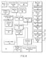
- FIG. 8is a block diagram showing a representative architecture of a portion of PC 20 that is optimized to function in a clinical environment.
- PC 20contains processor 50 that is connected to north bridge 64 and input/output controller hub (ICH) 56 or south bridge.
- the north bridgemay connect memory 54 and graphics controller 52 which may operate LCD 28 .
- a power source or inverter 100may be included and connected to battery 40 .
- Power source 100may be a significant source of heat, and as such may be thermally coupled to cooling system 51 .
- Cooling system 51may be controlled by cooling system controller 53 , which may receive input from one or more thermal sensors 68 .
- ICH 56may connect a multitude of input/output devices, which are discussed in more detail below, to PC 20 .
- Accelerometer 72 and thermal sensor(s) 68are connected via embedded controller 74 .
- ICH 56may extend USB, Ethernet, or similar input/output (I/O) connectors to docking station connector 47 .
- keyboard controller 70may receive user input via the various thumb controls/buttons 71 .
- the computermay be somewhat adaptable and customizable because each sensor may be assigned a unique identifier by a controller, such as keyboard controller 70 . The controller may use the identifier to communicate user input to the processor.
- Particular sensors, or thumb controlsmay be associated with particular features of the computer, such as the operation of the camera, RFID reader, or bar code scanner, while other sensors may be associable with the same or different features as specified by a user.
- PC 20may also have HDD 62 and/or SSD that is connected via ICH 56 .
- ICH 56may connect bar code scanner 38 , RFID reader 36 , camera 66 , finger print scanner 78 , digitizer 27 , and microphone array 80 .
- PC 20may also have speaker(s) 82 that are connected through the ICH.
- PC 20may also house a variety of radios that are also connected via ICH 56 .
- a WWAN transceiver and antenna 84may connect PC 20 to a wireless broadband network; a WiFi transceiver and antenna 86 may connect PC 20 to a wireless local area network; and a Bluetooth transceiver and antenna 88 may enable the computer to communicate with Bluetooth enabled devices.
- the PCmay contain multiple radios, it may be necessary to selectively activate and deactivate particular radios, such as the WWAN and WiFi radios, so that they do not transmit simultaneously.
- the remaining radiosmay be selectively activated or deactivated based on user input and automated processes, such as power management settings.
- a mapping drivermay also be included to map computer controls to the various additional integrated devices, such as the camera, RFID reader, and bar code scanner in a way that is independent of the operating system. This will allow the software used with the integrated devices to communicate with the thumb controls and/or associated indicators that may be controlled by the keyboard controller.
- the mapping drivermay also function to provide an interface between an operating system, such as Microsoft Windows VistaTM, and/or the BIOS of the computer.
- the mapping drivermay also communicate with drivers associated with the various integrated devices to obtain control settings such as input signals and output indicators.
- the drivermay interface with operating system's registry to determine configuration information associated with the various integrated devices and associated inputs and outputs.
- the drivermay interface with the BIOS of the computer and thereby implement control methods based on input from thermal sensors within the computer as noted above when the higher level operating system is not functional.
- a user interfacesuch as the Motion Computing Dashboard Utility, may be incorporated to control the integrated devices as well as other features of the computer.
- the computermay be sealed, it may be difficult to cool because a completely sealed cooling system can only cool through passive means. In other words, sealing the computer forecloses the option of cooling it by circulating cooler air from the ambient environment through the computer.
- the computermay either expose a user to an excessively hot surface or limit heat generation by limiting processing power. Limiting processing power, or throttling the processor, may render the computer less effective, but may be necessary to prevent the computer from sustaining damage caused by excessive heating.
- the computermay generate heat at even higher rates. Since the passive cooling system may offset the benefit of a faster processor, the limitations associated with passively cooling the computer may become a significant hindrance. Still, it is noted that in some circumstances, scaling back the performance of the processor to limit heat generation may be a viable mode of cooling.
- many processorsare equipped with built-in thermal sensors. These sensors and other thermal sensors installed in the computer may monitor thermal conditions at key points inside the computer. In a passively cooled system, these sensors may generate interrupt signals at particular temperatures to initiate processor limitations, automatic saving of sensitive system data, and even an emergency shut-down when a critical temperature is reached. Additionally, particular subsystems, such as the backlight of the LCD, can be powered down to conserve power and limit heat generation.
- the computermay have a chassis and one or more exterior plates that are designed to conduct heat away from the computer and dissipate it into the surrounding environment.
- These conductive elementsmay be thermally coupled to the portions of the computer that generate the most heat, such as the processor and power supply, by using thermal greases, heat pipes, heat spreading materials such as GraphTech's Spreadershield, a graphite based heat spreading material, and similar conductive materials.
- the frame and body of the computermay be made from a thermally conductive material, such as a magnesium-alloy.
- FIG. 9shows a rear view of PC 20 with the rear cover removed.
- the locations of active cooling componentscan be seen along with the other components located near handle 24 .
- PC 20houses microphones 80 that are connected via microphone cable 101 , along with electrical power source 100 that may power the backlight of the LCD.
- the power sourceis a power inverter that may convert power received from the DC power source of the device to AC power that is supplied to the backlight of the LCD.
- the computerhouses WWAN radio 84 .
- the computerhouses components of the partially sealed active cooling system. While the bulk of the components of PC 20 are sealed within sealed area 103 of PC 20 , an active cooling system may be necessary to adequately cool PC 20 .
- heat pipes 92may protrude across boundary 99 between sealed area 103 and unsealed area 102 that houses fan 90 and radiator 94 .
- Heat pipes 92may draw heat to the radiator from heat producing parts of PC 20 , such as the processor and power supply. Because the heat pipes must follow a complex path that cannot be easily formed from flat heat pipe material, heat pipes 92 may be formed from round heat pipe material and flattened on the ends to increase thermal conductivity and contact areas at locations where heat pipes 92 absorb or dissipate heat. In unsealed area 102 of PC 20 , heat pipes 92 may be coupled to radiator 94 .
- fan 90may circulate cooler air 96 from the ambient environment across radiator 94 so that heat from the radiator may be dissipated into the air that is then discharged as warmer air 98 . While this portion of PC 20 is open to the ambient environment, it should still be configured so that it can be sprayed with a disinfectant or cleaning material and wiped clean to the extent possible. Accordingly, it is desirable to select a fan that is easily replaceable and tolerant to moisture.
- a portable computeris disclosed that is optimized and equipped with a robust feature set that makes it ideal for use in medical environments and other challenging work environments.
- the portable computeris highly ergonomic, impact resistant, and resistant to moisture penetration and contamination from airborne contaminants.
- the deviceis also easily cleaned by virtue of its sealed design that makes it resistant to cleaning agents that may be used to remove dirt or kill germs and bacteria. It will be appreciated to those skilled in the art having the benefit of this disclosure that this invention is believed to provide a multi-purpose portable computer that has improved utility in the healthcare as well as other industries. Further modifications and alternative embodiments of various aspects of the invention will be apparent to those skilled in the art in view of this description.
Landscapes
- Engineering & Computer Science (AREA)
- Health & Medical Sciences (AREA)
- Life Sciences & Earth Sciences (AREA)
- Theoretical Computer Science (AREA)
- Computer Hardware Design (AREA)
- Physics & Mathematics (AREA)
- General Engineering & Computer Science (AREA)
- General Physics & Mathematics (AREA)
- Human Computer Interaction (AREA)
- Biomedical Technology (AREA)
- Medical Informatics (AREA)
- Animal Behavior & Ethology (AREA)
- General Health & Medical Sciences (AREA)
- Public Health (AREA)
- Veterinary Medicine (AREA)
- Molecular Biology (AREA)
- Surgery (AREA)
- Heart & Thoracic Surgery (AREA)
- Pathology (AREA)
- Biophysics (AREA)
- Power Engineering (AREA)
- Dermatology (AREA)
- Image Input (AREA)
- Telephone Function (AREA)
Abstract
Description
Claims (16)
Priority Applications (2)
| Application Number | Priority Date | Filing Date | Title |
|---|---|---|---|
| US12/028,411US8152071B2 (en) | 2008-02-08 | 2008-02-08 | Multi-purpose portable computer with integrated devices |
| PCT/US2009/032845WO2009100009A2 (en) | 2008-02-08 | 2009-02-02 | Multi-purpose portable computer with integrated devices |
Applications Claiming Priority (1)
| Application Number | Priority Date | Filing Date | Title |
|---|---|---|---|
| US12/028,411US8152071B2 (en) | 2008-02-08 | 2008-02-08 | Multi-purpose portable computer with integrated devices |
Publications (2)
| Publication Number | Publication Date |
|---|---|
| US20090200378A1 US20090200378A1 (en) | 2009-08-13 |
| US8152071B2true US8152071B2 (en) | 2012-04-10 |
Family
ID=40938063
Family Applications (1)
| Application Number | Title | Priority Date | Filing Date |
|---|---|---|---|
| US12/028,411Active2030-05-01US8152071B2 (en) | 2008-02-08 | 2008-02-08 | Multi-purpose portable computer with integrated devices |
Country Status (2)
| Country | Link |
|---|---|
| US (1) | US8152071B2 (en) |
| WO (1) | WO2009100009A2 (en) |
Cited By (54)
| Publication number | Priority date | Publication date | Assignee | Title |
|---|---|---|---|---|
| US20100127828A1 (en)* | 2008-11-21 | 2010-05-27 | Symbol Technologies, Inc. | Rfid reader with automatic near/far field interrogation mode switching, and related operating methods |
| US20120019806A1 (en)* | 2010-07-26 | 2012-01-26 | Faro Technologies, Inc. | Device for optically scanning and measuring an environment |
| US8384914B2 (en) | 2009-07-22 | 2013-02-26 | Faro Technologies, Inc. | Device for optically scanning and measuring an environment |
| US8625106B2 (en) | 2009-07-22 | 2014-01-07 | Faro Technologies, Inc. | Method for optically scanning and measuring an object |
| US8663764B2 (en) | 2011-09-20 | 2014-03-04 | Ticona Llc | Overmolded composite structure for an electronic device |
| EP2703940A2 (en) | 2012-08-31 | 2014-03-05 | Bluebird Inc. | Tablet personal computer |
| US8699036B2 (en) | 2010-07-29 | 2014-04-15 | Faro Technologies, Inc. | Device for optically scanning and measuring an environment |
| US8705012B2 (en) | 2010-07-26 | 2014-04-22 | Faro Technologies, Inc. | Device for optically scanning and measuring an environment |
| US8705016B2 (en) | 2009-11-20 | 2014-04-22 | Faro Technologies, Inc. | Device for optically scanning and measuring an environment |
| US8719474B2 (en) | 2009-02-13 | 2014-05-06 | Faro Technologies, Inc. | Interface for communication between internal and external devices |
| US8730477B2 (en) | 2010-07-26 | 2014-05-20 | Faro Technologies, Inc. | Device for optically scanning and measuring an environment |
| US8830485B2 (en) | 2012-08-17 | 2014-09-09 | Faro Technologies, Inc. | Device for optically scanning and measuring an environment |
| US20140333663A1 (en)* | 2013-05-07 | 2014-11-13 | Hajime Yamada | Slanted map |
| US8896819B2 (en) | 2009-11-20 | 2014-11-25 | Faro Technologies, Inc. | Device for optically scanning and measuring an environment |
| US20140379500A1 (en)* | 1997-12-23 | 2014-12-25 | Unwired Planet, Llc | System and method for controlling financial transactions over a wireless network |
| US8921513B2 (en) | 2011-09-20 | 2014-12-30 | Ticona Llc | Low halogen content disulfide washed polyarylene sulfide |
| US20150095045A1 (en)* | 2013-09-27 | 2015-04-02 | Varian Medical Systems, Inc. | Method and system for mobile high-energy radiation treatment environment |
| US8997362B2 (en) | 2012-07-17 | 2015-04-07 | Faro Technologies, Inc. | Portable articulated arm coordinate measuring machine with optical communications bus |
| US9009000B2 (en) | 2010-01-20 | 2015-04-14 | Faro Technologies, Inc. | Method for evaluating mounting stability of articulated arm coordinate measurement machine using inclinometers |
| US9005476B2 (en) | 2011-09-20 | 2015-04-14 | Ticona Llc | Polyarylene sulfide/liquid crystal polymer alloy and compositions including same |
| ES2538182A1 (en)* | 2013-12-17 | 2015-06-17 | Tecnofingers, S.L. | Modular platform for tablets and mobile phones |
| US9074883B2 (en) | 2009-03-25 | 2015-07-07 | Faro Technologies, Inc. | Device for optically scanning and measuring an environment |
| US9113023B2 (en) | 2009-11-20 | 2015-08-18 | Faro Technologies, Inc. | Three-dimensional scanner with spectroscopic energy detector |
| US9119307B2 (en) | 2011-09-20 | 2015-08-25 | Ticona Llc | Housing for a portable electronic device |
| US9163922B2 (en) | 2010-01-20 | 2015-10-20 | Faro Technologies, Inc. | Coordinate measurement machine with distance meter and camera to determine dimensions within camera images |
| US9168654B2 (en) | 2010-11-16 | 2015-10-27 | Faro Technologies, Inc. | Coordinate measuring machines with dual layer arm |
| US9210288B2 (en) | 2009-11-20 | 2015-12-08 | Faro Technologies, Inc. | Three-dimensional scanner with dichroic beam splitters to capture a variety of signals |
| USRE45854E1 (en) | 2006-07-03 | 2016-01-19 | Faro Technologies, Inc. | Method and an apparatus for capturing three-dimensional data of an area of space |
| US9329271B2 (en) | 2010-05-10 | 2016-05-03 | Faro Technologies, Inc. | Method for optically scanning and measuring an environment |
| US9365718B2 (en) | 2011-09-20 | 2016-06-14 | Ticona Llc | Low chlorine fiber filled melt processed polyarylene sulfide composition |
| US9372265B2 (en) | 2012-10-05 | 2016-06-21 | Faro Technologies, Inc. | Intermediate two-dimensional scanning with a three-dimensional scanner to speed registration |
| US9394430B2 (en) | 2012-04-13 | 2016-07-19 | Ticona Llc | Continuous fiber reinforced polyarylene sulfide |
| US9417056B2 (en) | 2012-01-25 | 2016-08-16 | Faro Technologies, Inc. | Device for optically scanning and measuring an environment |
| US9417316B2 (en) | 2009-11-20 | 2016-08-16 | Faro Technologies, Inc. | Device for optically scanning and measuring an environment |
| US9513107B2 (en) | 2012-10-05 | 2016-12-06 | Faro Technologies, Inc. | Registration calculation between three-dimensional (3D) scans based on two-dimensional (2D) scan data from a 3D scanner |
| US9529083B2 (en) | 2009-11-20 | 2016-12-27 | Faro Technologies, Inc. | Three-dimensional scanner with enhanced spectroscopic energy detector |
| US9551575B2 (en) | 2009-03-25 | 2017-01-24 | Faro Technologies, Inc. | Laser scanner having a multi-color light source and real-time color receiver |
| US9607239B2 (en) | 2010-01-20 | 2017-03-28 | Faro Technologies, Inc. | Articulated arm coordinate measurement machine having a 2D camera and method of obtaining 3D representations |
| US9613332B2 (en) | 2014-07-31 | 2017-04-04 | Blue Point Tec LLC | Devices, systems and methods for tracking and auditing shipment items |
| US9628775B2 (en) | 2010-01-20 | 2017-04-18 | Faro Technologies, Inc. | Articulated arm coordinate measurement machine having a 2D camera and method of obtaining 3D representations |
| US9739591B2 (en) | 2014-05-14 | 2017-08-22 | Faro Technologies, Inc. | Metrology device and method of initiating communication |
| US9746308B2 (en) | 2014-05-14 | 2017-08-29 | Faro Technologies, Inc. | Metrology device and method of performing an inspection |
| US9803969B2 (en) | 2014-05-14 | 2017-10-31 | Faro Technologies, Inc. | Metrology device and method of communicating with portable devices |
| US9829305B2 (en) | 2014-05-14 | 2017-11-28 | Faro Technologies, Inc. | Metrology device and method of changing operating system |
| US9903701B2 (en) | 2014-05-14 | 2018-02-27 | Faro Technologies, Inc. | Articulated arm coordinate measurement machine having a rotary switch |
| US9921046B2 (en) | 2014-05-14 | 2018-03-20 | Faro Technologies, Inc. | Metrology device and method of servicing |
| US9928394B2 (en) | 2014-09-03 | 2018-03-27 | Hewlett-Packard Development Company, L.P. | Protective case with barcode scanner |
| US9973231B1 (en) | 2017-03-20 | 2018-05-15 | International Business Machines Corporation | Protective structures to provide impact protection for portable devices |
| US9990042B2 (en) | 2013-07-10 | 2018-06-05 | Hewlett-Packard Development Company, L.P. | Sensor and tag to determine a relative position |
| US10067231B2 (en) | 2012-10-05 | 2018-09-04 | Faro Technologies, Inc. | Registration calculation of three-dimensional scanner data performed between scans based on measurements by two-dimensional scanner |
| US10175037B2 (en) | 2015-12-27 | 2019-01-08 | Faro Technologies, Inc. | 3-D measuring device with battery pack |
| US10281259B2 (en) | 2010-01-20 | 2019-05-07 | Faro Technologies, Inc. | Articulated arm coordinate measurement machine that uses a 2D camera to determine 3D coordinates of smoothly continuous edge features |
| US10466807B1 (en)* | 2018-11-13 | 2019-11-05 | Pioneer Square Brands, Inc. | Keyboard |
| US11036256B2 (en) | 2016-09-30 | 2021-06-15 | Hewlett-Packard Development Company, L.P. | Handles |
Families Citing this family (16)
| Publication number | Priority date | Publication date | Assignee | Title |
|---|---|---|---|---|
| US7969730B1 (en) | 2008-02-08 | 2011-06-28 | Motion Computer, Inc. | Portable computer with thermal control and power source shield |
| CN101581951B (en)* | 2008-05-14 | 2011-11-09 | 富准精密工业(深圳)有限公司 | Computer |
| US20110017828A1 (en)* | 2009-07-24 | 2011-01-27 | Jadak, Llc | Handheld optical imaging device and method |
| CN101872366A (en)* | 2010-06-25 | 2010-10-27 | 广州市旭龙条码设备有限公司 | Bar code acquiring terminal |
| FR2967798A1 (en)* | 2010-11-19 | 2012-05-25 | Ixentive Consulting Group | Device for digitizing identification inputs and identification forms for subscribing to e.g. mobile services, has terminal with digital fingerprinting mechanism and reader to read bar code on identity and subscriber identity module cards |
| US20130090946A1 (en)* | 2011-10-05 | 2013-04-11 | Thomas Kwok-Fah Foo | Systems and methods for imaging workflow |
| US9122813B2 (en) | 2012-03-06 | 2015-09-01 | Smsc Holdings S.A.R.L. | USB host determination of whether a USB device provides power via a USB coupling |
| US9218837B2 (en) | 2012-05-23 | 2015-12-22 | Hewlett-Packard Development Company, L.P. | Control of storage device |
| US9179567B2 (en)* | 2012-05-23 | 2015-11-03 | Asustek Computer Inc. | Electronic device |
| EP2976879A4 (en) | 2013-03-20 | 2016-10-12 | Lifetime Brands Inc | Method and apparatus for mobile quality management inspections |
| US9572901B2 (en)* | 2013-09-06 | 2017-02-21 | Hand Held Products, Inc. | Device having light source to reduce surface pathogens |
| KR101525200B1 (en)* | 2014-06-23 | 2015-06-04 | (주)블루버드 | Tablet pc |
| US9919547B2 (en)* | 2016-08-04 | 2018-03-20 | Datamax-O'neil Corporation | System and method for active printing consistency control and damage protection |
| DE102017108194A1 (en)* | 2017-04-18 | 2018-10-18 | Vorwerk & Co. Interholding Gmbh | Method for operating a self-propelled vehicle |
| KR102550771B1 (en)* | 2018-09-13 | 2023-07-04 | 삼성전자주식회사 | Electronic device including injection molded form, and injection molding structure |
| US20250181425A1 (en)* | 2023-12-04 | 2025-06-05 | Justin S. Diamond | Dynamically Generating Content via GUI-Programmable Input Devices and API Calls |
Citations (83)
| Publication number | Priority date | Publication date | Assignee | Title |
|---|---|---|---|---|
| US5086509A (en) | 1989-04-03 | 1992-02-04 | Mitsubishi Denki Kabushiki Kaisha | Thermally adaptive housing for hand held radio telephone device |
| US5424913A (en) | 1994-01-11 | 1995-06-13 | Dell Usa, L.P. | Heat sink/component access door for portable computers |
| US5430609A (en) | 1993-09-02 | 1995-07-04 | Kikinis; Dan | Microprocessor cooling in a portable computer |
| US5583742A (en) | 1993-12-15 | 1996-12-10 | Alps Electric Co., Ltd. | Computer with protective cover having outwardly projecting cushioning portions |
| US5625535A (en) | 1995-07-13 | 1997-04-29 | Hulsebosch; David A. | Compact construction for portable computer power supply |
| US5656876A (en) | 1992-09-21 | 1997-08-12 | Nokia Mobile Phones Limited | Battery pack |
| US5752011A (en) | 1994-06-20 | 1998-05-12 | Thomas; C. Douglas | Method and system for controlling a processor's clock frequency in accordance with the processor's temperature |
| US5835298A (en) | 1996-08-16 | 1998-11-10 | Telxon Corporation | Hard drive protection system and method |
| US5907471A (en) | 1997-12-29 | 1999-05-25 | Motorola, Inc. | Energy storage device with electromagnetic interference shield |
| JPH11143585A (en) | 1997-11-11 | 1999-05-28 | Matsushita Electric Ind Co Ltd | Information processing device with heat dissipation structure |
| US5931297A (en) | 1997-03-27 | 1999-08-03 | Weill; Christopher P. | Notebook computer protective cover |
| US5969940A (en) | 1995-06-08 | 1999-10-19 | International Business Machines Corporation | Mechanical structure of information processing device |
| US6119179A (en) | 1998-08-28 | 2000-09-12 | Pda Peripherals Inc. | Telecommunications adapter providing non-repudiable communications log and supplemental power for a portable programmable device |
| US6122167A (en) | 1998-06-02 | 2000-09-19 | Dell Usa, L.P. | Integrated hybrid cooling with EMI shielding for a portable computer |
| US6138826A (en) | 1998-02-02 | 2000-10-31 | Fuji Photo Film Co., Ltd. | Waterproof case for camera |
| US6145280A (en) | 1998-03-18 | 2000-11-14 | Ntk Powerdex, Inc. | Flexible packaging for polymer electrolytic cell and method of forming same |
| US6233464B1 (en) | 1999-05-14 | 2001-05-15 | Qualcomm Incorporated | Power on/off in combined PDA/telephone |
| US6262886B1 (en) | 1999-09-30 | 2001-07-17 | Apple Computer, Inc. | Translucent protective covering for a computer housing |
| US6267790B1 (en) | 1998-03-18 | 2001-07-31 | Ntk Powerdex, Inc. | Treatment of conductive feedthroughs for battery packaging |
| US6319199B1 (en) | 1998-10-26 | 2001-11-20 | David M. Sheehan | Portable data collection device |
| US6336080B1 (en) | 1996-01-16 | 2002-01-01 | Compaq Computer Corporation | Thermal management of computers |
| US20020053421A1 (en) | 1997-09-10 | 2002-05-09 | Kabushiki Kaisha Toshiba | Heat dissipating structure for electronic apparatus |
| US20020067520A1 (en) | 1999-12-07 | 2002-06-06 | Brown Barry Allen Thomas | Hand-held image capture apparatus |
| US20020085342A1 (en) | 2000-12-29 | 2002-07-04 | Shin-Chen Chen | Portable computer with shockproof function |
| US6567120B1 (en) | 1996-10-14 | 2003-05-20 | Nikon Corporation | Information processing apparatus having a photographic mode and a memo input mode |
| US20030184958A1 (en) | 2002-03-27 | 2003-10-02 | Chi-Lie Kao | Protective case for a tablet personal computer |
| US6657859B1 (en) | 2000-06-30 | 2003-12-02 | Intel Corporation | Device bay heat exchanger for a portable computing device |
| US6659274B2 (en) | 2001-12-14 | 2003-12-09 | Hewlett-Packard Development Company, L.P. | Waterproof casing for Hewlett-Packard Jornada portable personal computer |
| US20030236102A1 (en) | 2002-06-19 | 2003-12-25 | Fujitsu Limited | Electronic apparatus |
| US6684089B1 (en) | 2000-11-14 | 2004-01-27 | Inventec Appliances Corp. | Case structure of a data processing device |
| US20040107372A1 (en) | 2002-11-29 | 2004-06-03 | Toshikazu Morisawa | Electronic apparatus and method of setting an operation mode of the same |
| US6746638B1 (en) | 2000-05-31 | 2004-06-08 | Apple Computer, Inc. | Method of forming a computer casing |
| US6789611B1 (en) | 2000-01-04 | 2004-09-14 | Jia Hao Li | Bubble cycling heat exchanger |
| US6803144B2 (en) | 2001-11-01 | 2004-10-12 | Nokia Corporation | Battery pack for electronic device |
| US20040204041A1 (en) | 2000-06-16 | 2004-10-14 | Fillebrown Lisa A. | Wireless tablet for a personal wireless network |
| US20040201602A1 (en) | 2003-04-14 | 2004-10-14 | Invensys Systems, Inc. | Tablet computer system for industrial process design, supervisory control, and data management |
| US6809698B2 (en) | 2002-12-14 | 2004-10-26 | Antennigues Corp. | Broadband dual-frequency tablet antennas |
| US20050040224A1 (en) | 2001-09-11 | 2005-02-24 | Zonar Compliance Systems, Llc | System and process to record inspection compliance data |
| US6888332B2 (en) | 2000-06-16 | 2005-05-03 | Kabushiki Kaisha Toshiba | Computer system and method of controlling rotation speed of cooling fan |
| US20050128693A1 (en) | 2003-12-15 | 2005-06-16 | Katsunori Itoh | Electronic apparatus |
| US20050130721A1 (en) | 2003-12-12 | 2005-06-16 | Gartrell Andrew J. | Interlocking cover for mobile terminals |
| US20050139498A1 (en) | 2001-11-03 | 2005-06-30 | Jean Goros | Protective sleeve for small portable electronic devices |
| US6927978B2 (en) | 2003-02-10 | 2005-08-09 | Kabushiki Kaisha Toshiba | Electronic apparatus and method of cooling the electronic apparatus |
| US20050276018A1 (en) | 2004-06-14 | 2005-12-15 | Moore Earl W | Thermal management system for a portable computing device |
| US20050280984A1 (en) | 2004-06-18 | 2005-12-22 | Tatung Co., Ltd. | Tablet PC and base member coupling arrangement |
| US20060044288A1 (en) | 2004-06-18 | 2006-03-02 | Hiroshi Nakamura | Multi-functional electronic device utilizing a stylus pen |
| US20060057458A1 (en) | 2004-09-15 | 2006-03-16 | O'dea Michael J | Battery with integrated protection circuit |
| US7013558B2 (en) | 2000-03-21 | 2006-03-21 | Spraylat Corp. | Method for shielding an electronic component |
| US7016181B2 (en) | 2002-06-11 | 2006-03-21 | Fujitsu Limited | Information processing apparatus having magnesium body and printed circuit board |
| US20060125782A1 (en)* | 2001-03-29 | 2006-06-15 | Orchard John T | Method and apparatus for controlling a computing system |
| US20060139807A1 (en)* | 2002-10-03 | 2006-06-29 | Hitachi Global Storage Technologies | Magnetic disk protection mechanism, computer system comprising protection mechanism, protection method for magnetic disk, and program for protection method |
| US7145769B2 (en) | 2004-09-15 | 2006-12-05 | Hannstar Display Corporation | Portable liquid crystal display and the tablet PC |
| US7155202B2 (en) | 2003-07-10 | 2006-12-26 | University Of Florida Research Foundation, Inc. | Portable device medical assistant |
| US20070085015A1 (en) | 2005-10-14 | 2007-04-19 | Castleberry Donald E | Lightweight and rugged digital x-ray detector |
| US7209035B2 (en) | 2004-07-06 | 2007-04-24 | Catcher, Inc. | Portable handheld security device |
| US7221957B2 (en) | 2002-05-22 | 2007-05-22 | Sony Corporation | Portable information terminal, a control method for a portable information terminal, a program of a method of controlling a personal information terminal and a recording medium having recorded therein a program of a method of controlling a personal information terminal |
| US20070139873A1 (en) | 2001-11-19 | 2007-06-21 | Otter Products, Llc | Protective enclosure and watertight adapter for an interactive flat-panel controlled device |
| US7245482B2 (en) | 2004-06-09 | 2007-07-17 | Samsung Electronics Co., Ltd. | Portable computer with camera |
| US20070174152A1 (en) | 2003-12-08 | 2007-07-26 | Bjornberg David B | Handheld system for information acquisition, verification, recording, processing, display and communication |
| US20070188306A1 (en) | 2006-01-30 | 2007-08-16 | Sdgi Holdings, Inc. | Systems and methods for automated programming of RFID tags using machine readable indicia |
| US7273089B2 (en) | 2003-05-26 | 2007-09-25 | Kabushiki Kaisha Toshiba | Electronic apparatus having a heat-radiating unit for radiating heat of heat-generating components |
| US7278579B2 (en) | 2004-11-12 | 2007-10-09 | Siemens Medical Solutions Usa, Inc. | Patient information management system |
| US7286894B1 (en) | 2000-01-07 | 2007-10-23 | Pasco Scientific | Hand-held computer device and method for interactive data acquisition, analysis, annotation, and calibration |
| US20070282208A1 (en) | 2006-06-06 | 2007-12-06 | Bob Jacobs | Mobile computing device with integrated medical devices |
| US7312992B2 (en) | 2004-11-30 | 2007-12-25 | General Electric Company | Apparatus and method for transferring heat from processors |
| US20080019093A1 (en) | 2006-05-31 | 2008-01-24 | Kabushiki Kaisha Toshiba | Electronic device |
| US7325846B2 (en) | 2003-05-07 | 2008-02-05 | Hewlett-Packard Development Company, L.P. | Low profile mechanical assist hood latch |
| US7336489B1 (en) | 2006-08-01 | 2008-02-26 | Compal Electronics, Inc. | Waterproof thermal management module and portable |
| US20080081679A1 (en) | 2006-09-28 | 2008-04-03 | Casio Hitachi Mobile Communications Co., Ltd. | Waterproof structure |
| US20080094786A1 (en) | 2006-10-19 | 2008-04-24 | Guan-De Liou | Waterproof casing for a flat panel display |
| US20080123287A1 (en) | 2006-11-27 | 2008-05-29 | Addonit Limited | Casings for hand-held electronic devices |
| US7382607B2 (en) | 2006-02-16 | 2008-06-03 | Palm, Inc. | Housing for a portable computing device |
| US7388161B2 (en) | 2005-08-19 | 2008-06-17 | Quanta Computer Inc. | Electromagnetic interference shielding and grounding structure and the applications thereof |
| US20080144270A1 (en)* | 2006-12-15 | 2008-06-19 | Dal Porto Sandro F | Portable Data Storage Device |
| US7405930B2 (en) | 2004-06-30 | 2008-07-29 | Kabushiki Kaisha Toshiba | Electronic apparatus |
| US20080227507A1 (en) | 2007-03-16 | 2008-09-18 | Won Seok Joo | Cover for a mobile device and mobile device having same |
| US7428143B1 (en) | 2005-02-18 | 2008-09-23 | Motion Computing, Inc. | Tablet computer palette with extended bezel |
| US7446753B2 (en) | 2004-09-10 | 2008-11-04 | Hand Held Products, Inc. | Hand held computer device |
| US7495895B2 (en) | 2006-04-19 | 2009-02-24 | Carnevali Jeffrey D | Protective cover for device having touch screen |
| US7499232B2 (en)* | 2003-06-16 | 2009-03-03 | Apple Inc. | Media player with acceleration protection |
| US7514765B2 (en) | 2006-04-25 | 2009-04-07 | Dell Products L.P. | Solution of power consumption reduction for inverter covered by metal case |
| US20100008028A1 (en) | 2001-11-19 | 2010-01-14 | Otter Products, Llc | Protective enclosure for electronic device |
| US7674540B2 (en) | 2003-10-06 | 2010-03-09 | Societe Bic | Fuel cartridges for fuel cells and methods for making same |
- 2008
- 2008-02-08USUS12/028,411patent/US8152071B2/enactiveActive
- 2009
- 2009-02-02WOPCT/US2009/032845patent/WO2009100009A2/enactiveApplication Filing
Patent Citations (88)
| Publication number | Priority date | Publication date | Assignee | Title |
|---|---|---|---|---|
| US5086509A (en) | 1989-04-03 | 1992-02-04 | Mitsubishi Denki Kabushiki Kaisha | Thermally adaptive housing for hand held radio telephone device |
| US5656876A (en) | 1992-09-21 | 1997-08-12 | Nokia Mobile Phones Limited | Battery pack |
| US5430609A (en) | 1993-09-02 | 1995-07-04 | Kikinis; Dan | Microprocessor cooling in a portable computer |
| US5583742A (en) | 1993-12-15 | 1996-12-10 | Alps Electric Co., Ltd. | Computer with protective cover having outwardly projecting cushioning portions |
| US5424913A (en) | 1994-01-11 | 1995-06-13 | Dell Usa, L.P. | Heat sink/component access door for portable computers |
| US5974557A (en) | 1994-06-20 | 1999-10-26 | Thomas; C. Douglass | Method and system for performing thermal and power management for a computer |
| US5752011A (en) | 1994-06-20 | 1998-05-12 | Thomas; C. Douglas | Method and system for controlling a processor's clock frequency in accordance with the processor's temperature |
| US6487668B2 (en) | 1994-06-20 | 2002-11-26 | C. Douglass Thomas | Thermal and power management to computer systems |
| US6216235B1 (en) | 1994-06-20 | 2001-04-10 | C. Douglass Thomas | Thermal and power management for computer systems |
| US5969940A (en) | 1995-06-08 | 1999-10-19 | International Business Machines Corporation | Mechanical structure of information processing device |
| US5625535A (en) | 1995-07-13 | 1997-04-29 | Hulsebosch; David A. | Compact construction for portable computer power supply |
| US6336080B1 (en) | 1996-01-16 | 2002-01-01 | Compaq Computer Corporation | Thermal management of computers |
| US5835298A (en) | 1996-08-16 | 1998-11-10 | Telxon Corporation | Hard drive protection system and method |
| US6567120B1 (en) | 1996-10-14 | 2003-05-20 | Nikon Corporation | Information processing apparatus having a photographic mode and a memo input mode |
| US5931297A (en) | 1997-03-27 | 1999-08-03 | Weill; Christopher P. | Notebook computer protective cover |
| US20020053421A1 (en) | 1997-09-10 | 2002-05-09 | Kabushiki Kaisha Toshiba | Heat dissipating structure for electronic apparatus |
| JPH11143585A (en) | 1997-11-11 | 1999-05-28 | Matsushita Electric Ind Co Ltd | Information processing device with heat dissipation structure |
| US5907471A (en) | 1997-12-29 | 1999-05-25 | Motorola, Inc. | Energy storage device with electromagnetic interference shield |
| US6138826A (en) | 1998-02-02 | 2000-10-31 | Fuji Photo Film Co., Ltd. | Waterproof case for camera |
| US6145280A (en) | 1998-03-18 | 2000-11-14 | Ntk Powerdex, Inc. | Flexible packaging for polymer electrolytic cell and method of forming same |
| US6267790B1 (en) | 1998-03-18 | 2001-07-31 | Ntk Powerdex, Inc. | Treatment of conductive feedthroughs for battery packaging |
| US6122167A (en) | 1998-06-02 | 2000-09-19 | Dell Usa, L.P. | Integrated hybrid cooling with EMI shielding for a portable computer |
| US6119179A (en) | 1998-08-28 | 2000-09-12 | Pda Peripherals Inc. | Telecommunications adapter providing non-repudiable communications log and supplemental power for a portable programmable device |
| US6319199B1 (en) | 1998-10-26 | 2001-11-20 | David M. Sheehan | Portable data collection device |
| US6233464B1 (en) | 1999-05-14 | 2001-05-15 | Qualcomm Incorporated | Power on/off in combined PDA/telephone |
| US6262886B1 (en) | 1999-09-30 | 2001-07-17 | Apple Computer, Inc. | Translucent protective covering for a computer housing |
| US20020067520A1 (en) | 1999-12-07 | 2002-06-06 | Brown Barry Allen Thomas | Hand-held image capture apparatus |
| US6789611B1 (en) | 2000-01-04 | 2004-09-14 | Jia Hao Li | Bubble cycling heat exchanger |
| US7286894B1 (en) | 2000-01-07 | 2007-10-23 | Pasco Scientific | Hand-held computer device and method for interactive data acquisition, analysis, annotation, and calibration |
| US7013558B2 (en) | 2000-03-21 | 2006-03-21 | Spraylat Corp. | Method for shielding an electronic component |
| US6746638B1 (en) | 2000-05-31 | 2004-06-08 | Apple Computer, Inc. | Method of forming a computer casing |
| US20040204041A1 (en) | 2000-06-16 | 2004-10-14 | Fillebrown Lisa A. | Wireless tablet for a personal wireless network |
| US6888332B2 (en) | 2000-06-16 | 2005-05-03 | Kabushiki Kaisha Toshiba | Computer system and method of controlling rotation speed of cooling fan |
| US6657859B1 (en) | 2000-06-30 | 2003-12-02 | Intel Corporation | Device bay heat exchanger for a portable computing device |
| US6684089B1 (en) | 2000-11-14 | 2004-01-27 | Inventec Appliances Corp. | Case structure of a data processing device |
| US20020085342A1 (en) | 2000-12-29 | 2002-07-04 | Shin-Chen Chen | Portable computer with shockproof function |
| US20060125782A1 (en)* | 2001-03-29 | 2006-06-15 | Orchard John T | Method and apparatus for controlling a computing system |
| US20050040224A1 (en) | 2001-09-11 | 2005-02-24 | Zonar Compliance Systems, Llc | System and process to record inspection compliance data |
| US6803144B2 (en) | 2001-11-01 | 2004-10-12 | Nokia Corporation | Battery pack for electronic device |
| US20050139498A1 (en) | 2001-11-03 | 2005-06-30 | Jean Goros | Protective sleeve for small portable electronic devices |
| US20100008028A1 (en) | 2001-11-19 | 2010-01-14 | Otter Products, Llc | Protective enclosure for electronic device |
| US20070139873A1 (en) | 2001-11-19 | 2007-06-21 | Otter Products, Llc | Protective enclosure and watertight adapter for an interactive flat-panel controlled device |
| US6659274B2 (en) | 2001-12-14 | 2003-12-09 | Hewlett-Packard Development Company, L.P. | Waterproof casing for Hewlett-Packard Jornada portable personal computer |
| US20030184958A1 (en) | 2002-03-27 | 2003-10-02 | Chi-Lie Kao | Protective case for a tablet personal computer |
| US7221957B2 (en) | 2002-05-22 | 2007-05-22 | Sony Corporation | Portable information terminal, a control method for a portable information terminal, a program of a method of controlling a personal information terminal and a recording medium having recorded therein a program of a method of controlling a personal information terminal |
| US7016181B2 (en) | 2002-06-11 | 2006-03-21 | Fujitsu Limited | Information processing apparatus having magnesium body and printed circuit board |
| US20030236102A1 (en) | 2002-06-19 | 2003-12-25 | Fujitsu Limited | Electronic apparatus |
| US20060139807A1 (en)* | 2002-10-03 | 2006-06-29 | Hitachi Global Storage Technologies | Magnetic disk protection mechanism, computer system comprising protection mechanism, protection method for magnetic disk, and program for protection method |
| US20040107372A1 (en) | 2002-11-29 | 2004-06-03 | Toshikazu Morisawa | Electronic apparatus and method of setting an operation mode of the same |
| US6809698B2 (en) | 2002-12-14 | 2004-10-26 | Antennigues Corp. | Broadband dual-frequency tablet antennas |
| US6927978B2 (en) | 2003-02-10 | 2005-08-09 | Kabushiki Kaisha Toshiba | Electronic apparatus and method of cooling the electronic apparatus |
| US7456751B2 (en) | 2003-02-10 | 2008-11-25 | Kabushiki Kaisha Toshiba | Electronic apparatus and method of cooling the electronic apparatus |
| US20040201602A1 (en) | 2003-04-14 | 2004-10-14 | Invensys Systems, Inc. | Tablet computer system for industrial process design, supervisory control, and data management |
| US7325846B2 (en) | 2003-05-07 | 2008-02-05 | Hewlett-Packard Development Company, L.P. | Low profile mechanical assist hood latch |
| US7273089B2 (en) | 2003-05-26 | 2007-09-25 | Kabushiki Kaisha Toshiba | Electronic apparatus having a heat-radiating unit for radiating heat of heat-generating components |
| US7499232B2 (en)* | 2003-06-16 | 2009-03-03 | Apple Inc. | Media player with acceleration protection |
| US7155202B2 (en) | 2003-07-10 | 2006-12-26 | University Of Florida Research Foundation, Inc. | Portable device medical assistant |
| US7674540B2 (en) | 2003-10-06 | 2010-03-09 | Societe Bic | Fuel cartridges for fuel cells and methods for making same |
| US20070174152A1 (en) | 2003-12-08 | 2007-07-26 | Bjornberg David B | Handheld system for information acquisition, verification, recording, processing, display and communication |
| US20050130721A1 (en) | 2003-12-12 | 2005-06-16 | Gartrell Andrew J. | Interlocking cover for mobile terminals |
| US7184260B2 (en) | 2003-12-15 | 2007-02-27 | Fujitsu Limited | Electronic apparatus |
| US20050128693A1 (en) | 2003-12-15 | 2005-06-16 | Katsunori Itoh | Electronic apparatus |
| US7245482B2 (en) | 2004-06-09 | 2007-07-17 | Samsung Electronics Co., Ltd. | Portable computer with camera |
| US20050276018A1 (en) | 2004-06-14 | 2005-12-15 | Moore Earl W | Thermal management system for a portable computing device |
| US20050280984A1 (en) | 2004-06-18 | 2005-12-22 | Tatung Co., Ltd. | Tablet PC and base member coupling arrangement |
| US20060044288A1 (en) | 2004-06-18 | 2006-03-02 | Hiroshi Nakamura | Multi-functional electronic device utilizing a stylus pen |
| US7405930B2 (en) | 2004-06-30 | 2008-07-29 | Kabushiki Kaisha Toshiba | Electronic apparatus |
| US7209035B2 (en) | 2004-07-06 | 2007-04-24 | Catcher, Inc. | Portable handheld security device |
| US7446753B2 (en) | 2004-09-10 | 2008-11-04 | Hand Held Products, Inc. | Hand held computer device |
| US20060057458A1 (en) | 2004-09-15 | 2006-03-16 | O'dea Michael J | Battery with integrated protection circuit |
| US7145769B2 (en) | 2004-09-15 | 2006-12-05 | Hannstar Display Corporation | Portable liquid crystal display and the tablet PC |
| US7278579B2 (en) | 2004-11-12 | 2007-10-09 | Siemens Medical Solutions Usa, Inc. | Patient information management system |
| US7312992B2 (en) | 2004-11-30 | 2007-12-25 | General Electric Company | Apparatus and method for transferring heat from processors |
| US7428143B1 (en) | 2005-02-18 | 2008-09-23 | Motion Computing, Inc. | Tablet computer palette with extended bezel |
| US7388161B2 (en) | 2005-08-19 | 2008-06-17 | Quanta Computer Inc. | Electromagnetic interference shielding and grounding structure and the applications thereof |
| US20070085015A1 (en) | 2005-10-14 | 2007-04-19 | Castleberry Donald E | Lightweight and rugged digital x-ray detector |
| US20070188306A1 (en) | 2006-01-30 | 2007-08-16 | Sdgi Holdings, Inc. | Systems and methods for automated programming of RFID tags using machine readable indicia |
| US7382607B2 (en) | 2006-02-16 | 2008-06-03 | Palm, Inc. | Housing for a portable computing device |
| US7495895B2 (en) | 2006-04-19 | 2009-02-24 | Carnevali Jeffrey D | Protective cover for device having touch screen |
| US7514765B2 (en) | 2006-04-25 | 2009-04-07 | Dell Products L.P. | Solution of power consumption reduction for inverter covered by metal case |
| US20080019093A1 (en) | 2006-05-31 | 2008-01-24 | Kabushiki Kaisha Toshiba | Electronic device |
| US20070282208A1 (en) | 2006-06-06 | 2007-12-06 | Bob Jacobs | Mobile computing device with integrated medical devices |
| US7336489B1 (en) | 2006-08-01 | 2008-02-26 | Compal Electronics, Inc. | Waterproof thermal management module and portable |
| US20080081679A1 (en) | 2006-09-28 | 2008-04-03 | Casio Hitachi Mobile Communications Co., Ltd. | Waterproof structure |
| US20080094786A1 (en) | 2006-10-19 | 2008-04-24 | Guan-De Liou | Waterproof casing for a flat panel display |
| US20080123287A1 (en) | 2006-11-27 | 2008-05-29 | Addonit Limited | Casings for hand-held electronic devices |
| US20080144270A1 (en)* | 2006-12-15 | 2008-06-19 | Dal Porto Sandro F | Portable Data Storage Device |
| US20080227507A1 (en) | 2007-03-16 | 2008-09-18 | Won Seok Joo | Cover for a mobile device and mobile device having same |
Non-Patent Citations (8)
| Title |
|---|
| Doherty et al., U.S. Appl. No. 12/028,362 entitled "Portable Computer with Thermal Control and Power Source Shield," filed Feb. 8, 2008. |
| Doherty et al., U.S. Appl. No. 12/028,458 entitled "Ergonomic Solvent Resistant Portable Computer," filed Feb. 8, 2008. |
| Final Office Action mailed Oct. 25, 2010 for U.S. Appl. No. 12/634,340. |
| Final Office Action Mailed Sep. 4, 2009 for U.S. Appl. No. 12/028,362. |
| International Search Report & Written Opinion, PCT/US2009/032845, mailed Sep. 18, 2009. |
| Office Action mailed Feb. 3, 2010 for U.S. Appl. No. 12/028,458. |
| Office Action mailed Jun. 16, 2009 for U.S. Appl. No. 12/028,362. |
| Office Action mailed Jun. 29, 2010 for U.S. Patent Application No. 12/634,340. |
Cited By (76)
| Publication number | Priority date | Publication date | Assignee | Title |
|---|---|---|---|---|
| US20140379500A1 (en)* | 1997-12-23 | 2014-12-25 | Unwired Planet, Llc | System and method for controlling financial transactions over a wireless network |
| US9147185B2 (en)* | 1997-12-23 | 2015-09-29 | Unwired Planet, Llc | System and method for controlling financial transactions over a wireless network |
| US9135613B2 (en) | 1997-12-23 | 2015-09-15 | Unwired Planet, Llc | System and method for controlling financial transactions over a wireless network |
| US9111271B2 (en) | 1997-12-23 | 2015-08-18 | Unwired Planet, Llc | System and method for controlling financial transactions over a wireless network |
| USRE45854E1 (en) | 2006-07-03 | 2016-01-19 | Faro Technologies, Inc. | Method and an apparatus for capturing three-dimensional data of an area of space |
| US20100127828A1 (en)* | 2008-11-21 | 2010-05-27 | Symbol Technologies, Inc. | Rfid reader with automatic near/far field interrogation mode switching, and related operating methods |
| US8305192B2 (en)* | 2008-11-21 | 2012-11-06 | Symbol Technologies, Inc. | RFID reader with automatic near/far field interrogation mode switching, and related operating methods |
| US8719474B2 (en) | 2009-02-13 | 2014-05-06 | Faro Technologies, Inc. | Interface for communication between internal and external devices |
| US9551575B2 (en) | 2009-03-25 | 2017-01-24 | Faro Technologies, Inc. | Laser scanner having a multi-color light source and real-time color receiver |
| US9074883B2 (en) | 2009-03-25 | 2015-07-07 | Faro Technologies, Inc. | Device for optically scanning and measuring an environment |
| US8384914B2 (en) | 2009-07-22 | 2013-02-26 | Faro Technologies, Inc. | Device for optically scanning and measuring an environment |
| US8625106B2 (en) | 2009-07-22 | 2014-01-07 | Faro Technologies, Inc. | Method for optically scanning and measuring an object |
| US8705016B2 (en) | 2009-11-20 | 2014-04-22 | Faro Technologies, Inc. | Device for optically scanning and measuring an environment |
| US9113023B2 (en) | 2009-11-20 | 2015-08-18 | Faro Technologies, Inc. | Three-dimensional scanner with spectroscopic energy detector |
| US9210288B2 (en) | 2009-11-20 | 2015-12-08 | Faro Technologies, Inc. | Three-dimensional scanner with dichroic beam splitters to capture a variety of signals |
| US9417316B2 (en) | 2009-11-20 | 2016-08-16 | Faro Technologies, Inc. | Device for optically scanning and measuring an environment |
| US8896819B2 (en) | 2009-11-20 | 2014-11-25 | Faro Technologies, Inc. | Device for optically scanning and measuring an environment |
| US9529083B2 (en) | 2009-11-20 | 2016-12-27 | Faro Technologies, Inc. | Three-dimensional scanner with enhanced spectroscopic energy detector |
| US9628775B2 (en) | 2010-01-20 | 2017-04-18 | Faro Technologies, Inc. | Articulated arm coordinate measurement machine having a 2D camera and method of obtaining 3D representations |
| US10281259B2 (en) | 2010-01-20 | 2019-05-07 | Faro Technologies, Inc. | Articulated arm coordinate measurement machine that uses a 2D camera to determine 3D coordinates of smoothly continuous edge features |
| US9163922B2 (en) | 2010-01-20 | 2015-10-20 | Faro Technologies, Inc. | Coordinate measurement machine with distance meter and camera to determine dimensions within camera images |
| US9009000B2 (en) | 2010-01-20 | 2015-04-14 | Faro Technologies, Inc. | Method for evaluating mounting stability of articulated arm coordinate measurement machine using inclinometers |
| US9607239B2 (en) | 2010-01-20 | 2017-03-28 | Faro Technologies, Inc. | Articulated arm coordinate measurement machine having a 2D camera and method of obtaining 3D representations |
| US10060722B2 (en) | 2010-01-20 | 2018-08-28 | Faro Technologies, Inc. | Articulated arm coordinate measurement machine having a 2D camera and method of obtaining 3D representations |
| US9329271B2 (en) | 2010-05-10 | 2016-05-03 | Faro Technologies, Inc. | Method for optically scanning and measuring an environment |
| US9684078B2 (en) | 2010-05-10 | 2017-06-20 | Faro Technologies, Inc. | Method for optically scanning and measuring an environment |
| US8730477B2 (en) | 2010-07-26 | 2014-05-20 | Faro Technologies, Inc. | Device for optically scanning and measuring an environment |
| US8705012B2 (en) | 2010-07-26 | 2014-04-22 | Faro Technologies, Inc. | Device for optically scanning and measuring an environment |
| US8699007B2 (en)* | 2010-07-26 | 2014-04-15 | Faro Technologies, Inc. | Device for optically scanning and measuring an environment |
| US20120019806A1 (en)* | 2010-07-26 | 2012-01-26 | Faro Technologies, Inc. | Device for optically scanning and measuring an environment |
| US8699036B2 (en) | 2010-07-29 | 2014-04-15 | Faro Technologies, Inc. | Device for optically scanning and measuring an environment |
| US9168654B2 (en) | 2010-11-16 | 2015-10-27 | Faro Technologies, Inc. | Coordinate measuring machines with dual layer arm |
| US8663764B2 (en) | 2011-09-20 | 2014-03-04 | Ticona Llc | Overmolded composite structure for an electronic device |
| US9119307B2 (en) | 2011-09-20 | 2015-08-25 | Ticona Llc | Housing for a portable electronic device |
| US9005476B2 (en) | 2011-09-20 | 2015-04-14 | Ticona Llc | Polyarylene sulfide/liquid crystal polymer alloy and compositions including same |
| US9365718B2 (en) | 2011-09-20 | 2016-06-14 | Ticona Llc | Low chlorine fiber filled melt processed polyarylene sulfide composition |
| US8921513B2 (en) | 2011-09-20 | 2014-12-30 | Ticona Llc | Low halogen content disulfide washed polyarylene sulfide |
| US9417056B2 (en) | 2012-01-25 | 2016-08-16 | Faro Technologies, Inc. | Device for optically scanning and measuring an environment |
| US9394430B2 (en) | 2012-04-13 | 2016-07-19 | Ticona Llc | Continuous fiber reinforced polyarylene sulfide |
| US8997362B2 (en) | 2012-07-17 | 2015-04-07 | Faro Technologies, Inc. | Portable articulated arm coordinate measuring machine with optical communications bus |
| US8830485B2 (en) | 2012-08-17 | 2014-09-09 | Faro Technologies, Inc. | Device for optically scanning and measuring an environment |
| US9389645B2 (en) | 2012-08-31 | 2016-07-12 | Bluebird Inc. | Tablet personal computer with detachable auxiliary device |
| KR101447457B1 (en) | 2012-08-31 | 2014-10-07 | (주)블루버드 | Tablet pc |
| EP2703940A2 (en) | 2012-08-31 | 2014-03-05 | Bluebird Inc. | Tablet personal computer |
| US9618620B2 (en) | 2012-10-05 | 2017-04-11 | Faro Technologies, Inc. | Using depth-camera images to speed registration of three-dimensional scans |
| US9372265B2 (en) | 2012-10-05 | 2016-06-21 | Faro Technologies, Inc. | Intermediate two-dimensional scanning with a three-dimensional scanner to speed registration |
| US11815600B2 (en) | 2012-10-05 | 2023-11-14 | Faro Technologies, Inc. | Using a two-dimensional scanner to speed registration of three-dimensional scan data |
| US10067231B2 (en) | 2012-10-05 | 2018-09-04 | Faro Technologies, Inc. | Registration calculation of three-dimensional scanner data performed between scans based on measurements by two-dimensional scanner |
| US10203413B2 (en) | 2012-10-05 | 2019-02-12 | Faro Technologies, Inc. | Using a two-dimensional scanner to speed registration of three-dimensional scan data |
| US10739458B2 (en) | 2012-10-05 | 2020-08-11 | Faro Technologies, Inc. | Using two-dimensional camera images to speed registration of three-dimensional scans |
| US9513107B2 (en) | 2012-10-05 | 2016-12-06 | Faro Technologies, Inc. | Registration calculation between three-dimensional (3D) scans based on two-dimensional (2D) scan data from a 3D scanner |
| US9739886B2 (en) | 2012-10-05 | 2017-08-22 | Faro Technologies, Inc. | Using a two-dimensional scanner to speed registration of three-dimensional scan data |
| US9746559B2 (en) | 2012-10-05 | 2017-08-29 | Faro Technologies, Inc. | Using two-dimensional camera images to speed registration of three-dimensional scans |
| US11112501B2 (en) | 2012-10-05 | 2021-09-07 | Faro Technologies, Inc. | Using a two-dimensional scanner to speed registration of three-dimensional scan data |
| US11035955B2 (en) | 2012-10-05 | 2021-06-15 | Faro Technologies, Inc. | Registration calculation of three-dimensional scanner data performed between scans based on measurements by two-dimensional scanner |
| US20140333663A1 (en)* | 2013-05-07 | 2014-11-13 | Hajime Yamada | Slanted map |
| US9159301B2 (en)* | 2013-05-07 | 2015-10-13 | Honda Motor Co., Ltd. | Slanted map |
| US9990042B2 (en) | 2013-07-10 | 2018-06-05 | Hewlett-Packard Development Company, L.P. | Sensor and tag to determine a relative position |
| US11010850B1 (en) | 2013-09-27 | 2021-05-18 | Varian Medical Systems, Inc. | Method and system for mobile high-energy radiation treatment environment |
| US10210588B2 (en)* | 2013-09-27 | 2019-02-19 | Varian Medical Systems, Inc. | Method and system for mobile high-energy radiation treatment environment |
| US20150095045A1 (en)* | 2013-09-27 | 2015-04-02 | Varian Medical Systems, Inc. | Method and system for mobile high-energy radiation treatment environment |
| ES2538182A1 (en)* | 2013-12-17 | 2015-06-17 | Tecnofingers, S.L. | Modular platform for tablets and mobile phones |
| US9739591B2 (en) | 2014-05-14 | 2017-08-22 | Faro Technologies, Inc. | Metrology device and method of initiating communication |
| US9803969B2 (en) | 2014-05-14 | 2017-10-31 | Faro Technologies, Inc. | Metrology device and method of communicating with portable devices |
| US9746308B2 (en) | 2014-05-14 | 2017-08-29 | Faro Technologies, Inc. | Metrology device and method of performing an inspection |
| US9829305B2 (en) | 2014-05-14 | 2017-11-28 | Faro Technologies, Inc. | Metrology device and method of changing operating system |
| US9921046B2 (en) | 2014-05-14 | 2018-03-20 | Faro Technologies, Inc. | Metrology device and method of servicing |
| US9903701B2 (en) | 2014-05-14 | 2018-02-27 | Faro Technologies, Inc. | Articulated arm coordinate measurement machine having a rotary switch |
| US10415950B2 (en) | 2014-05-14 | 2019-09-17 | Faro Technologies, Inc. | Metrology device and method of performing an inspection |
| US9892378B2 (en) | 2014-07-31 | 2018-02-13 | BluePoint Mobile Solutoins, Inc. | Devices, systems and methods for tracking and auditing shipment items |
| US9613332B2 (en) | 2014-07-31 | 2017-04-04 | Blue Point Tec LLC | Devices, systems and methods for tracking and auditing shipment items |
| US9928394B2 (en) | 2014-09-03 | 2018-03-27 | Hewlett-Packard Development Company, L.P. | Protective case with barcode scanner |
| US10175037B2 (en) | 2015-12-27 | 2019-01-08 | Faro Technologies, Inc. | 3-D measuring device with battery pack |
| US11036256B2 (en) | 2016-09-30 | 2021-06-15 | Hewlett-Packard Development Company, L.P. | Handles |
| US9973231B1 (en) | 2017-03-20 | 2018-05-15 | International Business Machines Corporation | Protective structures to provide impact protection for portable devices |
| US10466807B1 (en)* | 2018-11-13 | 2019-11-05 | Pioneer Square Brands, Inc. | Keyboard |
Also Published As
| Publication number | Publication date |
|---|---|
| US20090200378A1 (en) | 2009-08-13 |
| WO2009100009A3 (en) | 2009-11-05 |
| WO2009100009A2 (en) | 2009-08-13 |
Similar Documents
| Publication | Publication Date | Title |
|---|---|---|
| US8152071B2 (en) | Multi-purpose portable computer with integrated devices | |
| US7821782B2 (en) | Ergonomic solvent resistant portable computer | |
| US7969730B1 (en) | Portable computer with thermal control and power source shield | |
| US7330923B2 (en) | Input devices and methods of operating same | |
| US8687351B2 (en) | Scanning jacket for a handheld device | |
| US10599445B2 (en) | Controls and indicators with on-screen cognitive aids | |
| US20070282208A1 (en) | Mobile computing device with integrated medical devices | |
| US8971049B1 (en) | Portable electronic device having integrated peripheral expansion module | |
| US9053250B2 (en) | Dual-mode tablet input system with primary computer wherein first mode is keyboard input with computer and second mode involves mirroring with computer | |
| RU2386161C2 (en) | Circuit of optical system for universal computing device | |
| KR101153144B1 (en) | Integrated control for navigation, authentication, power on and rotation | |
| JP5470051B2 (en) | Note capture device | |
| US20100265179A1 (en) | Computer apparatus with added functionality | |
| JP6295256B2 (en) | Ultrasound imaging device and ultrasound imaging system operated by mobile display device | |
| CN106557218A (en) | For the proximity test of the input mechanism of electronic equipment | |
| JP2011527478A (en) | Multi-touch touch screen with pen tracking | |
| CN104720837B (en) | medical equipment | |
| US9648287B2 (en) | Note capture device | |
| US20110249104A1 (en) | Peripheral for a Handheld Communication Device | |
| US20120162061A1 (en) | Activation objects for interactive systems | |
| US20120069054A1 (en) | Electronic display systems having mobile components | |
| US10921854B2 (en) | Electronic device with sensing strip | |
| US20090113104A1 (en) | Input devices and methods of operating same | |
| US20110001889A1 (en) | Personal computer | |
| US20220118921A1 (en) | Avn device |
Legal Events
| Date | Code | Title | Description |
|---|---|---|---|
| AS | Assignment | Owner name:MOTION COMPUTING, INC., TEXAS Free format text:ASSIGNMENT OF ASSIGNORS INTEREST;ASSIGNORS:DOHERTY, JOHN;COLLINS, MIKE;REEL/FRAME:020483/0768 Effective date:20080204 | |
| AS | Assignment | Owner name:SILICON VALLEY BANK,CALIFORNIA Free format text:SECURITY AGREEMENT;ASSIGNOR:MOTION COMPUTING, INC.;REEL/FRAME:024066/0234 Effective date:20100310 Owner name:SILICON VALLEY BANK, CALIFORNIA Free format text:SECURITY AGREEMENT;ASSIGNOR:MOTION COMPUTING, INC.;REEL/FRAME:024066/0234 Effective date:20100310 | |
| STCF | Information on status: patent grant | Free format text:PATENTED CASE | |
| AS | Assignment | Owner name:MOTION COMPUTING, INC., TEXAS Free format text:RELEASE BY SECURED PARTY;ASSIGNOR:SILICON VALLEY BANK;REEL/FRAME:035312/0120 Effective date:20140930 | |
| FPAY | Fee payment | Year of fee payment:4 | |
| AS | Assignment | Owner name:BANK OF AMERICA, N.A., NEW YORK Free format text:SECURITY AGREEMENT;ASSIGNOR:XPLORE TECHNOLOGIES CORP.;REEL/FRAME:043212/0430 Effective date:20170417 | |
| AS | Assignment | Owner name:XPLORE TECHNOLOGIES CORPORATION OF AMERICA, TEXAS Free format text:TRANSFER STATEMENT;ASSIGNOR:MOTION COMPUTING INC.;REEL/FRAME:046698/0795 Effective date:20150417 | |
| AS | Assignment | Owner name:XPLORE TECHNOLOGIES CORP., TEXAS Free format text:RELEASE OF SECURITY INTEREST RECORDED AT REEL/FRAME 043212/0430;ASSIGNOR:BANK OF AMERICA, N.A.;REEL/FRAME:047029/0494 Effective date:20180814 Owner name:XPLORE TECHNOLOGIES CORPORATION OF AMERICA, TEXAS Free format text:RELEASE OF SECURITY INTEREST RECORDED AT REEL/FRAME 043212/0430;ASSIGNOR:BANK OF AMERICA, N.A.;REEL/FRAME:047029/0494 Effective date:20180814 | |
| FEPP | Fee payment procedure | Free format text:ENTITY STATUS SET TO UNDISCOUNTED (ORIGINAL EVENT CODE: BIG.); ENTITY STATUS OF PATENT OWNER: LARGE ENTITY | |
| AS | Assignment | Owner name:JPMORGAN CHASE BANK, N.A., AS COLLATERAL AGENT, NE Free format text:SECURITY INTEREST;ASSIGNOR:XPLORE TECHNOLOGIES CORPORATION OF AMERICA;REEL/FRAME:047148/0495 Effective date:20181011 | |
| AS | Assignment | Owner name:ZEBRA TECHNOLOGIES CORPORATION, ILLINOIS Free format text:MERGER;ASSIGNOR:XPLORE TECHNOLOGIES CORPORATION OF AMERICA;REEL/FRAME:049703/0199 Effective date:20190516 | |
| AS | Assignment | Owner name:JP MORGAN CHASE BANK, N.A., AS COLLATERAL AGENT, N Free format text:NOTICE OF TRANSFER OF SECURITY INTEREST IN PATENTS;ASSIGNOR:ZEBRA TECHNOLOGIES CORPORATION;REEL/FRAME:050427/0248 Effective date:20190910 | |
| MAFP | Maintenance fee payment | Free format text:PAYMENT OF MAINTENANCE FEE, 8TH YEAR, LARGE ENTITY (ORIGINAL EVENT CODE: M1552); ENTITY STATUS OF PATENT OWNER: LARGE ENTITY Year of fee payment:8 | |
| AS | Assignment | Owner name:JPMORGAN CHASE BANK, N.A., NEW YORK Free format text:SECURITY INTEREST;ASSIGNORS:ZEBRA TECHNOLOGIES CORPORATION;LASER BAND, LLC;TEMPTIME CORPORATION;REEL/FRAME:053841/0212 Effective date:20200901 | |
| AS | Assignment | Owner name:ZEBRA TECHNOLOGIES CORPORATION, ILLINOIS Free format text:RELEASE OF SECURITY INTEREST - 364 - DAY;ASSIGNOR:JPMORGAN CHASE BANK, N.A.;REEL/FRAME:056036/0590 Effective date:20210225 Owner name:TEMPTIME CORPORATION, NEW JERSEY Free format text:RELEASE OF SECURITY INTEREST - 364 - DAY;ASSIGNOR:JPMORGAN CHASE BANK, N.A.;REEL/FRAME:056036/0590 Effective date:20210225 Owner name:LASER BAND, LLC, ILLINOIS Free format text:RELEASE OF SECURITY INTEREST - 364 - DAY;ASSIGNOR:JPMORGAN CHASE BANK, N.A.;REEL/FRAME:056036/0590 Effective date:20210225 | |
| MAFP | Maintenance fee payment | Free format text:PAYMENT OF MAINTENANCE FEE, 12TH YEAR, LARGE ENTITY (ORIGINAL EVENT CODE: M1553); ENTITY STATUS OF PATENT OWNER: LARGE ENTITY Year of fee payment:12 |