US8152010B2 - Container structure for removal of vacuum pressure - Google Patents
Container structure for removal of vacuum pressureDownload PDFInfo
- Publication number
- US8152010B2 US8152010B2US10/529,198US52919805AUS8152010B2US 8152010 B2US8152010 B2US 8152010B2US 52919805 AUS52919805 AUS 52919805AUS 8152010 B2US8152010 B2US 8152010B2
- Authority
- US
- United States
- Prior art keywords
- container
- pressure panel
- container according
- pressure
- panel
- Prior art date
- Legal status (The legal status is an assumption and is not a legal conclusion. Google has not performed a legal analysis and makes no representation as to the accuracy of the status listed.)
- Expired - Fee Related, expires
Links
- 239000003999initiatorSubstances0.000claimsabstractdescription36
- 239000007788liquidSubstances0.000claimsabstractdescription20
- 230000008859changeEffects0.000claimsdescription12
- 238000005728strengtheningMethods0.000claimsdescription7
- 238000001816coolingMethods0.000claimsdescription5
- 238000010438heat treatmentMethods0.000claimsdescription3
- 230000003014reinforcing effectEffects0.000abstractdescription2
- 238000013461designMethods0.000description11
- 238000000034methodMethods0.000description7
- 239000004033plasticSubstances0.000description6
- 229920003023plasticPolymers0.000description6
- 230000009471actionEffects0.000description5
- 238000009826distributionMethods0.000description4
- 230000035939shockEffects0.000description4
- 238000011161developmentMethods0.000description3
- 238000006073displacement reactionMethods0.000description3
- 239000011521glassSubstances0.000description3
- 239000000463materialSubstances0.000description3
- 230000004048modificationEffects0.000description3
- 238000012986modificationMethods0.000description3
- 229920000139polyethylene terephthalatePolymers0.000description3
- 239000005020polyethylene terephthalateSubstances0.000description3
- 230000008901benefitEffects0.000description2
- 230000008878couplingEffects0.000description2
- 238000010168coupling processMethods0.000description2
- 238000005859coupling reactionMethods0.000description2
- 239000007921spraySubstances0.000description2
- XLYOFNOQVPJJNP-UHFFFAOYSA-NwaterSubstancesOXLYOFNOQVPJJNP-UHFFFAOYSA-N0.000description2
- 230000001668ameliorated effectEffects0.000description1
- 238000003491arrayMethods0.000description1
- 230000015572biosynthetic processEffects0.000description1
- 235000019993champagneNutrition0.000description1
- 230000006835compressionEffects0.000description1
- 238000007906compressionMethods0.000description1
- 230000001010compromised effectEffects0.000description1
- 238000010276constructionMethods0.000description1
- 239000012263liquid productSubstances0.000description1
- 238000012423maintenanceMethods0.000description1
- 238000004519manufacturing processMethods0.000description1
- 238000009928pasteurizationMethods0.000description1
- -1polyethylene terephthalatePolymers0.000description1
- 230000008569processEffects0.000description1
- 239000000047productSubstances0.000description1
- 230000008719thickeningEffects0.000description1
Images


Classifications
- B—PERFORMING OPERATIONS; TRANSPORTING
- B65—CONVEYING; PACKING; STORING; HANDLING THIN OR FILAMENTARY MATERIAL
- B65D—CONTAINERS FOR STORAGE OR TRANSPORT OF ARTICLES OR MATERIALS, e.g. BAGS, BARRELS, BOTTLES, BOXES, CANS, CARTONS, CRATES, DRUMS, JARS, TANKS, HOPPERS, FORWARDING CONTAINERS; ACCESSORIES, CLOSURES, OR FITTINGS THEREFOR; PACKAGING ELEMENTS; PACKAGES
- B65D1/00—Rigid or semi-rigid containers having bodies formed in one piece, e.g. by casting metallic material, by moulding plastics, by blowing vitreous material, by throwing ceramic material, by moulding pulped fibrous material or by deep-drawing operations performed on sheet material
- B65D1/02—Bottles or similar containers with necks or like restricted apertures, designed for pouring contents
- B—PERFORMING OPERATIONS; TRANSPORTING
- B65—CONVEYING; PACKING; STORING; HANDLING THIN OR FILAMENTARY MATERIAL
- B65B—MACHINES, APPARATUS OR DEVICES FOR, OR METHODS OF, PACKAGING ARTICLES OR MATERIALS; UNPACKING
- B65B3/00—Packaging plastic material, semiliquids, liquids or mixed solids and liquids, in individual containers or receptacles, e.g. bags, sacks, boxes, cartons, cans, or jars
- B65B3/04—Methods of, or means for, filling the material into the containers or receptacles
- B—PERFORMING OPERATIONS; TRANSPORTING
- B65—CONVEYING; PACKING; STORING; HANDLING THIN OR FILAMENTARY MATERIAL
- B65D—CONTAINERS FOR STORAGE OR TRANSPORT OF ARTICLES OR MATERIALS, e.g. BAGS, BARRELS, BOTTLES, BOXES, CANS, CARTONS, CRATES, DRUMS, JARS, TANKS, HOPPERS, FORWARDING CONTAINERS; ACCESSORIES, CLOSURES, OR FITTINGS THEREFOR; PACKAGING ELEMENTS; PACKAGES
- B65D1/00—Rigid or semi-rigid containers having bodies formed in one piece, e.g. by casting metallic material, by moulding plastics, by blowing vitreous material, by throwing ceramic material, by moulding pulped fibrous material or by deep-drawing operations performed on sheet material
- B65D1/02—Bottles or similar containers with necks or like restricted apertures, designed for pouring contents
- B65D1/0223—Bottles or similar containers with necks or like restricted apertures, designed for pouring contents characterised by shape
- B65D1/0261—Bottom construction
- B65D1/0276—Bottom construction having a continuous contact surface, e.g. Champagne-type bottom
- B—PERFORMING OPERATIONS; TRANSPORTING
- B65—CONVEYING; PACKING; STORING; HANDLING THIN OR FILAMENTARY MATERIAL
- B65D—CONTAINERS FOR STORAGE OR TRANSPORT OF ARTICLES OR MATERIALS, e.g. BAGS, BARRELS, BOTTLES, BOXES, CANS, CARTONS, CRATES, DRUMS, JARS, TANKS, HOPPERS, FORWARDING CONTAINERS; ACCESSORIES, CLOSURES, OR FITTINGS THEREFOR; PACKAGING ELEMENTS; PACKAGES
- B65D1/00—Rigid or semi-rigid containers having bodies formed in one piece, e.g. by casting metallic material, by moulding plastics, by blowing vitreous material, by throwing ceramic material, by moulding pulped fibrous material or by deep-drawing operations performed on sheet material
- B65D1/12—Cans, casks, barrels, or drums
- B65D1/14—Cans, casks, barrels, or drums characterised by shape
- B—PERFORMING OPERATIONS; TRANSPORTING
- B65—CONVEYING; PACKING; STORING; HANDLING THIN OR FILAMENTARY MATERIAL
- B65D—CONTAINERS FOR STORAGE OR TRANSPORT OF ARTICLES OR MATERIALS, e.g. BAGS, BARRELS, BOTTLES, BOXES, CANS, CARTONS, CRATES, DRUMS, JARS, TANKS, HOPPERS, FORWARDING CONTAINERS; ACCESSORIES, CLOSURES, OR FITTINGS THEREFOR; PACKAGING ELEMENTS; PACKAGES
- B65D79/00—Kinds or details of packages, not otherwise provided for
- B65D79/005—Packages having deformable parts for indicating or neutralizing internal pressure-variations by other means than venting
- B65D79/008—Packages having deformable parts for indicating or neutralizing internal pressure-variations by other means than venting the deformable part being located in a rigid or semi-rigid container, e.g. in bottles or jars
- B65D79/0081—Packages having deformable parts for indicating or neutralizing internal pressure-variations by other means than venting the deformable part being located in a rigid or semi-rigid container, e.g. in bottles or jars in the bottom part thereof
- B—PERFORMING OPERATIONS; TRANSPORTING
- B29—WORKING OF PLASTICS; WORKING OF SUBSTANCES IN A PLASTIC STATE IN GENERAL
- B29C—SHAPING OR JOINING OF PLASTICS; SHAPING OF MATERIAL IN A PLASTIC STATE, NOT OTHERWISE PROVIDED FOR; AFTER-TREATMENT OF THE SHAPED PRODUCTS, e.g. REPAIRING
- B29C49/00—Blow-moulding, i.e. blowing a preform or parison to a desired shape within a mould; Apparatus therefor
- B29C49/42—Component parts, details or accessories; Auxiliary operations
- B29C49/4273—Auxiliary operations after the blow-moulding operation not otherwise provided for
- B29C49/4283—Deforming the finished article
- B—PERFORMING OPERATIONS; TRANSPORTING
- B65—CONVEYING; PACKING; STORING; HANDLING THIN OR FILAMENTARY MATERIAL
- B65B—MACHINES, APPARATUS OR DEVICES FOR, OR METHODS OF, PACKAGING ARTICLES OR MATERIALS; UNPACKING
- B65B61/00—Auxiliary devices, not otherwise provided for, for operating on sheets, blanks, webs, binding material, containers or packages
- B65B61/24—Auxiliary devices, not otherwise provided for, for operating on sheets, blanks, webs, binding material, containers or packages for shaping or reshaping completed packages
- B—PERFORMING OPERATIONS; TRANSPORTING
- B67—OPENING, CLOSING OR CLEANING BOTTLES, JARS OR SIMILAR CONTAINERS; LIQUID HANDLING
- B67C—CLEANING, FILLING WITH LIQUIDS OR SEMILIQUIDS, OR EMPTYING, OF BOTTLES, JARS, CANS, CASKS, BARRELS, OR SIMILAR CONTAINERS, NOT OTHERWISE PROVIDED FOR; FUNNELS
- B67C3/00—Bottling liquids or semiliquids; Filling jars or cans with liquids or semiliquids using bottling or like apparatus; Filling casks or barrels with liquids or semiliquids
- B67C3/02—Bottling liquids or semiliquids; Filling jars or cans with liquids or semiliquids using bottling or like apparatus
- B67C3/22—Details
- B67C2003/226—Additional process steps or apparatuses related to filling with hot liquids, e.g. after-treatment
Definitions
- This inventionrelates generally to a container structure that allows for the removal of vacuum pressure. This is achieved by inverting a transversely oriented vacuum pressure panel located in the lower end-wall, or base region of the container.
- so called ‘hot fill’ containersare well known in prior art, whereby manufacturers supply PET containers for various liquids which are filled into the containers and the liquid product is at an elevated temperature, typically at or around 85 degrees C. (185 degrees F.).
- the containeris manufactured to withstand the thermal shock of holding a heated liquid, resulting in a ‘heat-set’ plastic container. This thermal shock is a result of either introducing the liquid hot at filling, or heating the liquid after it is introduced into the container.
- vacuum pressureshave been accommodated by the use of vacuum panels, which distort inwardly under vacuum pressure.
- Prior artreveals many vertically oriented vacuum panels that allow containers to withstand the rigors of a hot fill procedure. Such vertically oriented vacuum panels generally lie parallel to the longitudinal axis of a container and flex inwardly under vacuum pressure toward this longitudinal axis.
- Silversdoes provide for the base region to be strengthened by coupling it to the standing ring of the container, in order to assist preventing unwanted outward movement of the inwardly inclined or flat portion when a heated liquid builds up initial internal pressure in a newly filled and capped container.
- This couplingis achieved by rib structures, which also serve to strengthen the flat region. Whilst this may strengthen the region in order to allow more vacuum force to be applied to it, the ribs conversely further reduce flexibility within the base region, and therefore reduce flexibility.
- the present inventionrelates to a hot-fill container which is a development of the hot-fill container described in our international application WO 02/18213 (the PCT specification), which specification is incorporated herein in its entirety where appropriate.
- a semi-rigid containerwas provided that had a substantially vertically folding vacuum panel portion.
- Such a transversely oriented vacuum panel portionincluded an initiator portion and a control portion which generally resisted being expanded from the collapsed state.
- a further and alternative object of the present invention in all its embodiments, all the objects to be read disjunctively,is to at least provide the public with a useful choice.
- a containerhaving a longitudinal axis, an upper portion having an opening into said container, a body portion extending from said upper portion to a lower portion, said lower portion including a base, said base closing off an end of said container, said container having at least one substantially transversely oriented pressure panel portion located in said lower portion, said pressure panel portion being capable of folding from one longitudinally inclined position to an inverted position to compensate for a change of pressure induced within the container.
- a containerhas a longitudinal axis and a base, and at least one substantially transversely oriented vacuum panel portion located adjacent to said base, said vacuum panel portion being adapted in use to fold from a longitudinally inclined position to an inverted position to compensate for a change of pressure induced within the container following cooling of a liquid within the container after it has been capped, such that less force is exerted on the internal walls of said container.
- a containerhas a longitudinal axis, a side wall and a base closing off one end, said container having a single substantially transversely oriented vacuum panel portion located within the base and joined to the side wall by a decoupling or hinge structure, said vacuum panel portion being adapted in use to fold from a longitudinally inclined position to an inverted position to compensate for a change of pressure induced within the container.
- the vacuum panel portionmay include an initiator section and a control section, said initiator section providing for folding before said control section.
- a decoupling structureconnects the pressure panel portion with the body portion and is of an area which allows for greater inward and upward longitudinal movement of the pressure panel.
- the vacuum panel portionhas no strengthening ribs to restrain substantial longitudinal movement and inversion.
- the vacuum panel portionmay include fluting structures or the like to allow an even circumferential distribution of folding forces to provide for increased control over folding the panel portion from one inclined position to another and to assist in preventing unwanted return to the original position.
- the container standing supportis provided by a lower part of the container sidewall that provides a replacement container standing support.
- a method of compensating for a change in pressure in a container as defined in any one of the preceding eight paragraphsincludes applying a force to the or each said panel portion to cause said folding to occur.
- FIG. 1shows a cross-sectional view of a hot-fill container according to one possible embodiment of the invention in its pre-collapsed condition
- FIG. 2shows the container of FIG. 1 in its collapsed position
- FIG. 3shows the base of FIG. 1 before collapsing
- FIG. 4shows the base of FIG. 2 following collapsing
- FIG. 5shows an underneath view of the base of the container of FIG. 1 before collapsing.
- FIG. 6shows the base of FIG. 1 before collapsing
- FIG. 7shows the base of FIG. 2 following collapsing
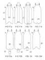
- FIG. 8 ashows a cross-sectional view of a hot-fill container according to an alternative embodiment of the invention in its pre-collapsed condition
- FIG. 8 bshows a side view of the container shown in FIGS. 5 b and 9 through line C-C;
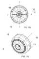
- FIG. 9shows an underneath view of the base of the container of FIGS. 8 a and 8 b and FIG. 10 before collapsing
- FIG. 10shows a cross-sectional view of the container shown in FIG. 9 through line D-D
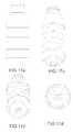
- FIGS. 11 a - dshow cross-sectional views of the container according to an alternative embodiment of the invention incorporating a pusher to provide panel folding
- FIGS. 12 a - dshow cross-sectional views of the container according to a further alternative embodiment of the invention incorporating a pusher to provide panel folding
- FIG. 13shows the base of an alternative embodiment of the invention before collapsing
- FIG. 14shows the base of FIG. 13 during the initial stages of collapsing
- FIGS. 15 a - bshow side and cross-sectional views of the container shown in FIG. 9 including outwardly projecting fluting;
- FIG. 15 cshows an underneath view of the base of the container of FIGS. 15 a and 15 b with dotted contour section lines through lines E-E and F-F;
- FIG. 15 dshows a perspective view of the base of the container of FIGS. 15 a - c;
- FIG. 16 ashows a side view of a container of FIG. 16 c according to an alternative embodiment including inwardly projecting fluting through Line I-I;
- FIG. 16 bshows a cross-sectional view of the base of the container of FIG. 16 c through Line J-J;
- FIG. 16 cshows an underneath view of the base of the container of FIGS. 16 a and 16 b with dotted contour section lines through lines G-G and H-H;
- FIG. 16 dshows a perspective view of the base of the container of FIGS. 16 a - c;
- FIGS. 17 a - dshow side, side perspective, end perspective and end views respectively of the container of FIG. 15 .
- FIGS. 18 a - dshow side, side perspective, end perspective and end views respectively of the container of FIG. 16 ;
- FIG. 19 ashows a side view of a hot-filled container of an alternative embodiment in its pre-collapsed condition
- FIG. 19 bshows a cross-sectional view of the container of FIG. 19 a through the line C-C in an initial stage of collapsing.
- containershave typically been provided with a series of vacuum panels around their sidewalls and an optimized base portion.
- the vacuum panelsdeform inwardly, and the base deforms upwardly, under the influence of the vacuum forces. This prevents unwanted distortion elsewhere in the container.
- the containeris still subjected to internal vacuum force.
- the panels and basemerely provide a suitably resistant structure against that force. The more resistant the structure the more vacuum force will be present. Additionally, end users can feel the vacuum panels when holding the containers.
- the present inventionrelates to hot-fill containers and a structure that provides for the substantial removal or substantial negation of vacuum pressure. This allows much greater design freedom and light weighting opportunities as there is no longer any requirement for the structure to be resistant to vacuum forces which would otherwise mechanically distort the container.
- the hot-ill container of the POT specificationhas positioned an outwardly inclined and transversely oriented vacuum panel between the lower portion of the side wall and the inwardly domed base region. In this position the container has poor stability, insofar as the base region is very narrow in diameter and does not allow for a good standing ring support.
- a decoupling structurethat provides a hinge joint to the juncture of the vacuum panel and the lower sidewall. This decoupling structure provides for a larger range of longitudinal movement of the vacuum panel than would occur if the panel was coupled to the side wall by way of ribs for example.
- the decoupling structuretherefore provides for increased deflection of the initiator portion, allowing increased movement of the panel portion longitudinally away from the previously outwardly inclined position, enabling the panel portion to fold inwardly relative to the container and upwardly relative to the initial base position.
- the lower sidewallis therefore subjected to lower force during such inversion. During this action, the base portion is translated longitudinally upward and into the container.
- the decoupling structureallows for the vacuum panel to now form part of the container base portion. This development has at least two important advantages.
- the transversely oriented vacuum panelis effectively completely removed from view as it is forced from an outward position to an inward position.
- any design or shapecan now be utilized, without regard for integrity against vacuum forces found in hot-fill packages.
- the decoupling structureprovides for the panel to become displaced longitudinally so that there is no contact between any part of the panel or upwardly domed base portion with the contact surface below. A standing ring is then provided by the lower sidewall immediately adjacent the decoupling structure.
- the initiator portionby gaining greater control over the inverting motion and forces, it is possible to allow the initiator portion to share the same steep angle as the control portion. This allows for increased volume displacement during inversion and increased resistance to any reversion back to the original position.
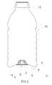
- FIG. 1shows, by way of example only, and in a diagrammatic cross sectional view, a container in the form of a bottle. This is referenced generally by arrow 10 with a typical neck portion 12 and a side wall 9 extending to a lower portion of the side wall 11 and an underneath base portion 2 .
- the container 10will typically be blow moulded from any suitable plastics material but typically this will be polyethylene terephthalate (PET).
- PETpolyethylene terephthalate
- the base 2is shown provided with a plurality of reinforcing ribs 3 so as to form the typical “champagne” base although this is merely by way of example only.
- FIG. 1the lower side wall portion 11 , which operates as a pressure panel, is shown in its unfolded position so that a ring or annular portion 6 is positioned above the level of the bottom of the base 2 which is forming the standing ring or support 4 for the container 10 .
- FIG. 2the lower side wall portion 11 is shown having folded inwardly so that the ring or annular portion 6 is positioned below the level of the bottom of the base 2 and is forming the new standing ring or support for the container 10 .
- an instep or recess 8 and decoupling structure 13immediately adjacent the ring or annular portion 6 there may be an instep or recess 8 and decoupling structure 13 , in this case a substantially flat, non-ribbed region, which after folding enables the base portion 2 to effectively completely disappear within the bottom of the container and above the line A-A.
- decoupling structure 13Many other configurations for the decoupling structure 13 are envisioned, however.
- the base 2 with its strengthening ribs 3is shown surrounded by the bottom annular portion 11 of the side wall 9 and the annular structure 13 .
- the bottom portion 11is shown in this particular embodiment as having an initiator portion 1 which forms part of the collapsing or inverting section which yields to a longitudinally-directed collapsing force before the rest of the collapsing or folding section.
- the base 2is shown provided within the typical base standing ring 4 , which will be the first support position for the container 10 prior to the inversion of the folding panel.
- control portion 5Associated with the initiator portion 1 is a control portion 5 which in this embodiment is a more steeply angled inverting section which will resist standing from the collapsed state.
- the panel control portion 5is generally set with an angle ⁇ varying between 30 degrees and 45 degrees. It is preferable to ensure an angle is set above 10 degrees at least.
- the initiator portion 1may in this embodiment have a lesser angle ⁇ of perhaps at least 10 degrees less than the control portion.
- control portion 5may be initially set to be outwardly inclined by approximately 35 degrees and will then provide an inversion and angle change of approximately 70 degrees.
- the initiator portionmay in this example be 20 degrees.
- the initiator portionmay be reconfigured so that pressure panel 11 would provide essentially a continuous conical area about the base 2 .
- initiator portion 1 and the control portion 5 of the embodiment of the preceding figureswill now be at a common angle, such that they form a uniformly inclined panel portion.
- initiator portion 1may still be configured to provide the area of least resistance to inversion, such that although it shares the same angular extent as the control portion 5 , it still provides an initial area of collapse or inversion.
- initiator portion 1causes the pressure panel 11 to begin inversion from the widest diameter adjacent the decoupling structure 13 .
- FIGS. 19 a and 19 bSuch an arrangement is shown in FIGS. 19 a and 19 b.
- the container side walls 9are ‘glass-like’ in construction in that there are no additional strengthening ribs or panels as might be typically found in a container, particularly if required to withstand the forces of vacuum pressure. Additionally, however, structures may be added to the conical portions of the vacuum panel 11 in order to add further control over the inversion process.
- the conical portion of the vacuum panel 11may be divided into fluted regions. Referring to FIGS. 8 a and 9 especially, panel portions that are convex outwardly, and evenly distributed around the central axis create regions of greater angular set 19 ( ⁇ ) and regions of lesser angular set 18 ( ⁇ ), may provide for greater control over inversion of the panel.
- Such geometryprovides increased resistance to reversion of the panel, and a more even distribution of forces when in the inverted position.
- FIGS. 15 a - c and 17 a - dconvex or downwardly outwardly projecting flutes are shown.
- Concave or inwardly directed fluting arrangementsare also envisioned, in addition to outwardly directed flutes.
- Inwardly directed flutesoffer less resistance to initial inverting forces, coupled with increased resistance to reverting back out to the original position. In this way they behave in much the same manner as ribs to prevent the panel being forced back out to the outwardly inclined position, but allow for hinge movement from the first outwardly inclined position to the inwardly inclined position.
- Such inwardly or outwardly directed flutes or projectionsfunction as ribs to increase the force required to invert the panel.
- the mechanical action applied to invert the panelwill be sufficient to overcome any rib-strengthened panel, and when the mechanical action is removed the rib-strengthened panel, for example by strong flutes, will be very resistant to reversion to the original position if the container is dropped or shocked.
- FIGS. 16 a - d and 18 a - dconcave or upwardly inwardly projecting flutes are shown, the contour lines G and H of FIG. 16 c illustrating this concavity through two cross-sectional reliefs.
- the containermay be blow moulded with the pressure panel 20 in the inwardly or upwardly inclined position.
- a forcecould be imposed on the folding panel 20 such as by means of a mechanical pusher 21 introduced through the neck region and forced downwardly in order to place the panel in the outwardly inclined position prior to use as a vacuum container for example, as shown in FIG. 11 d.
- a forcecould be imposed on the folding panel 20 such as by means of a mechanical pusher 22 or the creation of some relative movement of the bottle base relative to a punch or the like, in order to force the panel 20 from an outwardly inclined position to an inwardly inclined position.
- Any deformation whereby the bottle shape was distorted prior to inversion of the panel 20would be removed as internal volume is forcibly reduced.
- the vacuum within the containeris removed as the inversion of the panel 20 causes a rise in pressure. Such a rise in pressure reduces vacuum pressure until ambient pressure is reached or even a slightly positive pressure is achieved.
- the panelmay be inverted in the manner shown in FIGS. 12 a - d in order to provide a panel to accommodate internal force such as is found in pasteurization and the like. In such a way the panel will provide relief against the internal pressure generated and then be capable of accommodating the resulting vacuum force generated when the product cools down.
- the panelwill be inverted from an upwardly inclined position FIGS. 11 a to 11 b to a downwardly inclined position as shown in FIGS. 12 a - d , except that the mechanical action is not provided.
- the forceis instead provided by the internal pressure of the contents.
- decoupling or hinge structures 13may also be provided many different decoupling or hinge structures 13 without departing from the scope of the invention. With particular reference to FIGS. 6 and 7 , it can be seen that the side of the decoupling structure 13 that is provided for the pressure panel 11 may be of an enlarged area to provide for increased longitudinal movement upwards into the container following inversion.
- the widest portions 30 of the pressure panel 11may invert earlier than the narrower portions 31 .
- the initiator portionmay be constructed with this in mind, to allow for thinner material and so on, to provide for the panel 11 to begin inverting where it has the greater diameter, ahead of the narrower sections of the panel.
- the portion 30 of the panelwhich is radially set more distant from the central axis of the container inverts ahead of portion 31 to act as the initiator portion.
Landscapes
- Engineering & Computer Science (AREA)
- Mechanical Engineering (AREA)
- Ceramic Engineering (AREA)
- Containers Having Bodies Formed In One Piece (AREA)
- Filling Of Jars Or Cans And Processes For Cleaning And Sealing Jars (AREA)
- Packages (AREA)
- Pressure Vessels And Lids Thereof (AREA)
- Separation, Recovery Or Treatment Of Waste Materials Containing Plastics (AREA)
- Packaging Frangible Articles (AREA)
- Rigid Containers With Two Or More Constituent Elements (AREA)
- Cartons (AREA)
- Vacuum Packaging (AREA)
Abstract
Description
Claims (70)
Priority Applications (23)
| Application Number | Priority Date | Filing Date | Title |
|---|---|---|---|
| US11/413,124US8381940B2 (en) | 2002-09-30 | 2006-04-28 | Pressure reinforced plastic container having a moveable pressure panel and related method of processing a plastic container |
| US11/704,368US8584879B2 (en) | 2000-08-31 | 2007-02-09 | Plastic container having a deep-set invertible base and related methods |
| US11/704,338US8127955B2 (en) | 2000-08-31 | 2007-02-09 | Container structure for removal of vacuum pressure |
| US12/885,533US8720163B2 (en) | 2002-09-30 | 2010-09-19 | System for processing a pressure reinforced plastic container |
| US13/412,572US9145223B2 (en) | 2000-08-31 | 2012-03-05 | Container structure for removal of vacuum pressure |
| US13/415,831US9731884B2 (en) | 2000-08-31 | 2012-03-08 | Method for handling a hot-filled plastic bottle having a deep-set invertible base |
| US13/442,846US9211968B2 (en) | 2002-09-30 | 2012-04-09 | Container structure for removal of vacuum pressure |
| US13/476,997US20140123603A1 (en) | 2000-08-31 | 2012-05-21 | Plastic container having a deep-set invertible base and related methods |
| US13/752,377US9969517B2 (en) | 2002-09-30 | 2013-01-28 | Systems and methods for handling plastic containers having a deep-set invertible base |
| US13/775,995US9802730B2 (en) | 2002-09-30 | 2013-02-25 | Methods of compensating for vacuum pressure changes within a plastic container |
| US14/083,066US9387971B2 (en) | 2000-08-31 | 2013-11-18 | Plastic container having a deep-set invertible base and related methods |
| US14/142,882US9878816B2 (en) | 2002-09-30 | 2013-12-29 | Systems for compensating for vacuum pressure changes within a plastic container |
| US14/187,217US9624018B2 (en) | 2002-09-30 | 2014-02-21 | Container structure for removal of vacuum pressure |
| US14/499,031US10315796B2 (en) | 2002-09-30 | 2014-09-26 | Pressure reinforced deformable plastic container with hoop rings |
| US14/687,867US10246238B2 (en) | 2000-08-31 | 2015-04-15 | Plastic container having a deep-set invertible base and related methods |
| US14/968,781US10273072B2 (en) | 2002-09-30 | 2015-12-14 | Container structure for removal of vacuum pressure |
| US15/074,791US10435223B2 (en) | 2000-08-31 | 2016-03-18 | Method of handling a plastic container having a moveable base |
| US15/287,707US10683127B2 (en) | 2000-08-31 | 2016-10-06 | Plastic container having a movable base |
| US15/485,029US20180065791A1 (en) | 2002-09-30 | 2017-04-11 | Container Structure for Removal of Vacuum Pressure |
| US16/372,355US11565866B2 (en) | 2000-08-31 | 2019-04-01 | Plastic container having a deep-set invertible base and related methods |
| US16/396,640US11377286B2 (en) | 2002-09-30 | 2019-04-27 | Container structure for removal of vacuum pressure |
| US16/436,393US10661939B2 (en) | 2003-07-30 | 2019-06-10 | Pressure reinforced plastic container and related method of processing a plastic container |
| US16/594,524US11565867B2 (en) | 2000-08-31 | 2019-10-07 | Method of handling a plastic container having a moveable base |
Applications Claiming Priority (3)
| Application Number | Priority Date | Filing Date | Title |
|---|---|---|---|
| NZ521694ANZ521694A (en) | 2002-09-30 | 2002-09-30 | Container structure for removal of vacuum pressure |
| NZ521694 | 2002-09-30 | ||
| PCT/NZ2003/000220WO2004028910A1 (en) | 2002-09-30 | 2003-09-30 | Container structure for removal of vacuum pressure |
Related Parent Applications (4)
| Application Number | Title | Priority Date | Filing Date |
|---|---|---|---|
| PCT/NZ2003/000220A-371-Of-InternationalWO2004028910A1 (en) | 2000-08-31 | 2003-09-30 | Container structure for removal of vacuum pressure |
| US14/187,217ContinuationUS9624018B2 (en) | 2002-09-30 | 2014-02-21 | Container structure for removal of vacuum pressure |
| US14/187,227ContinuationUS10351325B2 (en) | 2002-09-30 | 2014-02-22 | Container structure for removal of vacuum pressure |
| US14/687,867Continuation-In-PartUS10246238B2 (en) | 2000-08-31 | 2015-04-15 | Plastic container having a deep-set invertible base and related methods |
Related Child Applications (5)
| Application Number | Title | Priority Date | Filing Date |
|---|---|---|---|
| US11/413,124Continuation-In-PartUS8381940B2 (en) | 2000-08-31 | 2006-04-28 | Pressure reinforced plastic container having a moveable pressure panel and related method of processing a plastic container |
| US11/704,368Continuation-In-PartUS8584879B2 (en) | 2000-08-31 | 2007-02-09 | Plastic container having a deep-set invertible base and related methods |
| US11/704,338Continuation-In-PartUS8127955B2 (en) | 2000-08-31 | 2007-02-09 | Container structure for removal of vacuum pressure |
| US13/442,846ContinuationUS9211968B2 (en) | 2002-09-30 | 2012-04-09 | Container structure for removal of vacuum pressure |
| US14/083,066Continuation-In-PartUS9387971B2 (en) | 2000-08-31 | 2013-11-18 | Plastic container having a deep-set invertible base and related methods |
Publications (2)
| Publication Number | Publication Date |
|---|---|
| US20060138074A1 US20060138074A1 (en) | 2006-06-29 |
| US8152010B2true US8152010B2 (en) | 2012-04-10 |
Family
ID=32041073
Family Applications (7)
| Application Number | Title | Priority Date | Filing Date |
|---|---|---|---|
| US10/529,198Expired - Fee RelatedUS8152010B2 (en) | 2000-08-31 | 2003-09-30 | Container structure for removal of vacuum pressure |
| US13/442,846Expired - LifetimeUS9211968B2 (en) | 2002-09-30 | 2012-04-09 | Container structure for removal of vacuum pressure |
| US14/187,217Expired - Fee RelatedUS9624018B2 (en) | 2002-09-30 | 2014-02-21 | Container structure for removal of vacuum pressure |
| US14/187,227Expired - Fee RelatedUS10351325B2 (en) | 2002-09-30 | 2014-02-22 | Container structure for removal of vacuum pressure |
| US14/968,781Expired - LifetimeUS10273072B2 (en) | 2002-09-30 | 2015-12-14 | Container structure for removal of vacuum pressure |
| US15/485,029AbandonedUS20180065791A1 (en) | 2002-09-30 | 2017-04-11 | Container Structure for Removal of Vacuum Pressure |
| US16/396,640Expired - LifetimeUS11377286B2 (en) | 2002-09-30 | 2019-04-27 | Container structure for removal of vacuum pressure |
Family Applications After (6)
| Application Number | Title | Priority Date | Filing Date |
|---|---|---|---|
| US13/442,846Expired - LifetimeUS9211968B2 (en) | 2002-09-30 | 2012-04-09 | Container structure for removal of vacuum pressure |
| US14/187,217Expired - Fee RelatedUS9624018B2 (en) | 2002-09-30 | 2014-02-21 | Container structure for removal of vacuum pressure |
| US14/187,227Expired - Fee RelatedUS10351325B2 (en) | 2002-09-30 | 2014-02-22 | Container structure for removal of vacuum pressure |
| US14/968,781Expired - LifetimeUS10273072B2 (en) | 2002-09-30 | 2015-12-14 | Container structure for removal of vacuum pressure |
| US15/485,029AbandonedUS20180065791A1 (en) | 2002-09-30 | 2017-04-11 | Container Structure for Removal of Vacuum Pressure |
| US16/396,640Expired - LifetimeUS11377286B2 (en) | 2002-09-30 | 2019-04-27 | Container structure for removal of vacuum pressure |
Country Status (26)
| Country | Link |
|---|---|
| US (7) | US8152010B2 (en) |
| EP (2) | EP1565381A4 (en) |
| JP (2) | JP4673060B2 (en) |
| KR (1) | KR101009434B1 (en) |
| CN (3) | CN103287647B (en) |
| AR (1) | AR041443A1 (en) |
| AU (2) | AU2003267885A1 (en) |
| BG (1) | BG109143A (en) |
| BR (1) | BR0314820B1 (en) |
| CA (1) | CA2499928C (en) |
| CO (1) | CO5720986A2 (en) |
| EC (1) | ECSP055766A (en) |
| GE (1) | GEP20074059B (en) |
| HU (1) | HU227635B1 (en) |
| MX (1) | MXPA05003291A (en) |
| MY (1) | MY177251A (en) |
| NZ (2) | NZ521694A (en) |
| PE (1) | PE20040240A1 (en) |
| PL (1) | PL202811B1 (en) |
| RO (1) | RO122720B1 (en) |
| RU (1) | RU2342293C2 (en) |
| SG (1) | SG147317A1 (en) |
| SK (1) | SK287929B6 (en) |
| TW (1) | TWI310751B (en) |
| WO (1) | WO2004028910A1 (en) |
| ZA (1) | ZA200502616B (en) |
Cited By (22)
| Publication number | Priority date | Publication date | Assignee | Title |
|---|---|---|---|---|
| US20080047964A1 (en)* | 2000-08-31 | 2008-02-28 | C02Pac | Plastic container having a deep-set invertible base and related methods |
| US20100219152A1 (en)* | 2007-07-30 | 2010-09-02 | Sidel Participations | Container including a base provided with a deformable membrane |
| US20110210133A1 (en)* | 2002-09-30 | 2011-09-01 | David Melrose | Pressure reinforced plastic container and related method of processing a plastic container |
| US20120180437A1 (en)* | 2004-12-20 | 2012-07-19 | David Murray Melrose | Method of processing a container and base cup structure for removal of vacuum pressure |
| US20130068779A1 (en)* | 2002-09-30 | 2013-03-21 | David Murray Melrose | Container structure for removal of vacuum pressure |
| US20130153529A1 (en)* | 2010-09-30 | 2013-06-20 | Yoshino Kogyosho Co., Ltd. | Bottle |
| US20130270214A1 (en)* | 2010-09-22 | 2013-10-17 | Red Bull Gmbh | Bottom structure for a plastic bottle |
| US20130312368A1 (en)* | 2000-08-31 | 2013-11-28 | John Denner | Plastic container having a deep-set invertible base and related methods |
| US20140069937A1 (en)* | 2000-08-31 | 2014-03-13 | Co2Pac Limited | Plastic container having a deep-set invertible base and related methods |
| US20140083059A1 (en)* | 2012-09-21 | 2014-03-27 | Krones Ag | Method and device for transporting containers filled with fluid |
| USD708953S1 (en) | 2013-03-15 | 2014-07-15 | The Folger Coffee Company | Container |
| WO2015126404A1 (en)* | 2014-02-20 | 2015-08-27 | Amcor Limited | Vacuum base for container |
| US9145223B2 (en) | 2000-08-31 | 2015-09-29 | Co2 Pac Limited | Container structure for removal of vacuum pressure |
| USD802852S1 (en)* | 2015-12-11 | 2017-11-14 | Doskocil Manufacturing Company, Inc. | Bottle |
| US9828166B2 (en)* | 2012-12-28 | 2017-11-28 | SOCIETE ANONYME DES EAUX MINERALES D'EVIAN et en abrégé “S.A.E.M.E.” | Self collapsible blow moulded plastic thin-walled containers and a dispensing method using same |
| US9969517B2 (en) | 2002-09-30 | 2018-05-15 | Co2Pac Limited | Systems and methods for handling plastic containers having a deep-set invertible base |
| US10246238B2 (en) | 2000-08-31 | 2019-04-02 | Co2Pac Limited | Plastic container having a deep-set invertible base and related methods |
| US10968006B2 (en)* | 2014-08-21 | 2021-04-06 | Amcor Rigid Packaging Usa, Llc | Container base including hemispherical actuating diaphragm |
| US11565867B2 (en) | 2000-08-31 | 2023-01-31 | C02Pac Limited | Method of handling a plastic container having a moveable base |
| US11891227B2 (en) | 2019-01-15 | 2024-02-06 | Amcor Rigid Packaging Usa, Llc | Vertical displacement container base |
| US11897656B2 (en) | 2007-02-09 | 2024-02-13 | Co2Pac Limited | Plastic container having a movable base |
| US11993443B2 (en) | 2007-02-09 | 2024-05-28 | Co2Pac Limited | Method of handling a plastic container having a moveable base |
Families Citing this family (112)
| Publication number | Priority date | Publication date | Assignee | Title |
|---|---|---|---|---|
| TWI228476B (en) | 2000-08-31 | 2005-03-01 | Co2 Pac Ltd | Semi-rigid collapsible container |
| US7543713B2 (en) | 2001-04-19 | 2009-06-09 | Graham Packaging Company L.P. | Multi-functional base for a plastic, wide-mouth, blow-molded container |
| US20140123603A1 (en)* | 2000-08-31 | 2014-05-08 | John Denner | Plastic container having a deep-set invertible base and related methods |
| US7900425B2 (en) | 2005-10-14 | 2011-03-08 | Graham Packaging Company, L.P. | Method for handling a hot-filled container having a moveable portion to reduce a portion of a vacuum created therein |
| US6922153B2 (en)* | 2003-05-13 | 2005-07-26 | Credo Technology Corporation | Safety detection and protection system for power tools |
| US9394072B2 (en) | 2003-05-23 | 2016-07-19 | Amcor Limited | Hot-fill container |
| US8276774B2 (en) | 2003-05-23 | 2012-10-02 | Amcor Limited | Container base structure responsive to vacuum related forces |
| US9751679B2 (en) | 2003-05-23 | 2017-09-05 | Amcor Limited | Vacuum absorbing bases for hot-fill containers |
| US8616395B2 (en) | 2003-05-23 | 2013-12-31 | Amcor Limited | Hot-fill container having vacuum accommodating base and cylindrical portions |
| US6942116B2 (en) | 2003-05-23 | 2005-09-13 | Amcor Limited | Container base structure responsive to vacuum related forces |
| US7150372B2 (en)* | 2003-05-23 | 2006-12-19 | Amcor Limited | Container base structure responsive to vacuum related forces |
| EP1923348A1 (en)* | 2003-07-30 | 2008-05-21 | Graham Packaging Company, L.P. | Container Handling System |
| NZ569422A (en)* | 2003-07-30 | 2010-02-26 | Graham Packaging Co | Container filling with base projection inverted during transportation, and being pushed up after filling |
| AU2011205106B2 (en)* | 2003-07-30 | 2013-05-23 | Graham Packaging Company, L.P. | Container handling system |
| JP4769791B2 (en) | 2004-03-11 | 2011-09-07 | グラハム パッケージング カンパニー,エル ピー | Plastic container transport method |
| US10611544B2 (en) | 2004-07-30 | 2020-04-07 | Co2Pac Limited | Method of handling a plastic container having a moveable base |
| WO2006034231A1 (en)* | 2004-09-20 | 2006-03-30 | Graham Packaging Company, L.P. | Container with cavity base |
| US8017065B2 (en) | 2006-04-07 | 2011-09-13 | Graham Packaging Company L.P. | System and method for forming a container having a grip region |
| US8075833B2 (en) | 2005-04-15 | 2011-12-13 | Graham Packaging Company L.P. | Method and apparatus for manufacturing blow molded containers |
| AU2011203263B2 (en)* | 2005-10-14 | 2013-08-15 | Co2Pac Limited | System and method for handling a container with a vacuum panel in the container body |
| JP4825535B2 (en)* | 2006-02-14 | 2011-11-30 | 北海製罐株式会社 | Method for producing a bottle filled with contents |
| US7799264B2 (en)* | 2006-03-15 | 2010-09-21 | Graham Packaging Company, L.P. | Container and method for blowmolding a base in a partial vacuum pressure reduction setup |
| JP4953674B2 (en)* | 2006-03-23 | 2012-06-13 | 北海製罐株式会社 | Plastic bottle |
| JP2007269376A (en)* | 2006-03-31 | 2007-10-18 | Toyo Seikan Kaisha Ltd | Plastic container deformation apparatus and plastic container deformation method |
| US9707711B2 (en) | 2006-04-07 | 2017-07-18 | Graham Packaging Company, L.P. | Container having outwardly blown, invertible deep-set grips |
| US8747727B2 (en) | 2006-04-07 | 2014-06-10 | Graham Packaging Company L.P. | Method of forming container |
| JP2007290772A (en)* | 2006-04-27 | 2007-11-08 | Hokkai Can Co Ltd | Synthetic resin bottle and method for producing synthetic resin bottle |
| JP4877487B2 (en)* | 2006-06-19 | 2012-02-15 | 東洋製罐株式会社 | Manufacturing method for products filled with liquid contents in plastic bottles |
| MX2008016303A (en) | 2006-07-03 | 2009-01-16 | Hokkai Can | Method and device for producing content filling bottle. |
| JP5019810B2 (en)* | 2006-07-18 | 2012-09-05 | 北海製罐株式会社 | Synthetic resin bottle and manufacturing method thereof |
| JP4814726B2 (en)* | 2006-08-25 | 2011-11-16 | 北海製罐株式会社 | Method for producing a bottle filled with contents |
| JP4858698B2 (en)* | 2006-09-14 | 2012-01-18 | 東洋製罐株式会社 | Plastic bottle |
| JP4858700B2 (en)* | 2006-10-18 | 2012-01-18 | 東洋製罐株式会社 | Volume reduction method for plastic bottles |
| GB2443807A (en)* | 2006-11-15 | 2008-05-21 | Plastic Can Company Ltd | Method and apparatus for making a container with a pressure accommodating base |
| JP4985938B2 (en)* | 2006-12-28 | 2012-07-25 | 東洋製罐株式会社 | Manufacturing method and manufacturing apparatus of product filled with content liquid in plastic bottle |
| US20230127553A1 (en)* | 2007-02-09 | 2023-04-27 | Co2Pac Limited | Plastic container having a deep-set invertible base and related methods |
| JP4917911B2 (en)* | 2007-02-22 | 2012-04-18 | 北海製罐株式会社 | Method for producing a bottle filled with contents |
| US20090298383A1 (en)* | 2007-09-15 | 2009-12-03 | Yarro Justin C | Thin-walled blow-formed tossable bottle with reinforced intra-fin cavities |
| JP5205637B2 (en)* | 2007-10-16 | 2013-06-05 | 北海製罐株式会社 | Synthetic resin bottle bottom recessed device |
| JP5034076B2 (en)* | 2007-10-23 | 2012-09-26 | 北海製罐株式会社 | Method and apparatus for inspecting bottom of synthetic resin bottle |
| US8313686B2 (en)* | 2008-02-07 | 2012-11-20 | Amcor Limited | Flex ring base |
| CA2719488C (en)* | 2008-03-27 | 2016-07-12 | Constar International, Inc. | Container base having volume absorption panel |
| US10703617B2 (en)* | 2008-05-19 | 2020-07-07 | David Murray Melrose | Method for controlled container headspace adjustment |
| TWI472459B (en) | 2008-05-19 | 2015-02-11 | Melrose David | Head space modification method for removing vacuum pressure and device thereof |
| WO2009151562A1 (en)* | 2008-06-05 | 2009-12-17 | Justin Yarro | Thin-walled tossable container with sidewall protrusions and reinforced cavities |
| US8627944B2 (en) | 2008-07-23 | 2014-01-14 | Graham Packaging Company L.P. | System, apparatus, and method for conveying a plurality of containers |
| AU2013270455B2 (en)* | 2008-11-27 | 2016-05-26 | Yoshino Kogyosho Co., Ltd. | Synthetic resin bottle |
| JP5472792B2 (en)* | 2009-04-30 | 2014-04-16 | 株式会社吉野工業所 | Synthetic resin housing |
| CN103057778B (en)* | 2008-11-27 | 2017-04-26 | 株式会社吉野工业所 | Synthetic resin bottle |
| US8636944B2 (en) | 2008-12-08 | 2014-01-28 | Graham Packaging Company L.P. | Method of making plastic container having a deep-inset base |
| MX340688B (en)* | 2008-12-31 | 2016-07-21 | Plastipak Packaging Inc | Hot-fillable plastic container with flexible base feature. |
| US7926243B2 (en) | 2009-01-06 | 2011-04-19 | Graham Packaging Company, L.P. | Method and system for handling containers |
| EP2583904B1 (en)* | 2009-01-29 | 2015-03-04 | Yoshino Kogyosho Co., Ltd. | Container with folded-back bottom wall |
| US20130283729A1 (en)* | 2009-02-10 | 2013-10-31 | Plastipak Packaging, Inc. | System and method for pressurizing a plastic container |
| CN102639095A (en)* | 2009-10-02 | 2012-08-15 | 株式会社细川洋行 | Storing container |
| US20110113732A1 (en)* | 2009-11-13 | 2011-05-19 | The Coca-Cola Company | Method of isolating column loading and mitigating deformation of shaped metal vessels |
| WO2011062512A1 (en)* | 2009-11-18 | 2011-05-26 | David Murray Melrose | Pressure sealing method for headspace modification |
| US10518933B2 (en)* | 2009-12-04 | 2019-12-31 | Plastipak Packaging, Inc. | Stackable plastic container |
| FR2954287B1 (en) | 2009-12-17 | 2012-08-03 | Sidel Participations | CONTAINER WITH DEFORMABLE FLANKS |
| US8444002B2 (en)* | 2010-02-19 | 2013-05-21 | Graham Packaging Lc, L.P. | Pressure compensating bases for polymeric containers |
| US8668100B2 (en) | 2010-06-30 | 2014-03-11 | S.C. Johnson & Son, Inc. | Bottles with top loading resistance |
| JP6245491B2 (en)* | 2010-10-29 | 2017-12-13 | 株式会社吉野工業所 | Synthetic resin round frame |
| US8962114B2 (en) | 2010-10-30 | 2015-02-24 | Graham Packaging Company, L.P. | Compression molded preform for forming invertible base hot-fill container, and systems and methods thereof |
| US9133006B2 (en) | 2010-10-31 | 2015-09-15 | Graham Packaging Company, L.P. | Systems, methods, and apparatuses for cooling hot-filled containers |
| USD660714S1 (en) | 2010-12-06 | 2012-05-29 | S.C. Johnson & Son, Inc. | Bottle |
| US8662329B2 (en) | 2010-12-06 | 2014-03-04 | S.C. Johnson & Son, Inc. | Bottle with top loading resistance with front and back ribs |
| US8851311B2 (en) | 2010-12-06 | 2014-10-07 | S.C. Johnson & Son, Inc. | Bottle with top loading resistance |
| JP5584929B2 (en)* | 2010-12-17 | 2014-09-10 | サントリーホールディングス株式会社 | Resin container |
| FR2969987B1 (en)* | 2010-12-29 | 2013-02-01 | Sidel Participations | CORNER CONTAINER WITH INNER WAVE SIDED |
| US9994378B2 (en) | 2011-08-15 | 2018-06-12 | Graham Packaging Company, L.P. | Plastic containers, base configurations for plastic containers, and systems, methods, and base molds thereof |
| US9150320B2 (en) | 2011-08-15 | 2015-10-06 | Graham Packaging Company, L.P. | Plastic containers having base configurations with up-stand walls having a plurality of rings, and systems, methods, and base molds thereof |
| US10532848B2 (en)* | 2011-08-31 | 2020-01-14 | Amcor Rigid Plastics Usa, Llc | Lightweight container base |
| US10538357B2 (en) | 2011-08-31 | 2020-01-21 | Amcor Rigid Plastics Usa, Llc | Lightweight container base |
| US8919587B2 (en) | 2011-10-03 | 2014-12-30 | Graham Packaging Company, L.P. | Plastic container with angular vacuum panel and method of same |
| CN102496985B (en) | 2011-12-09 | 2014-05-28 | 雷星亮 | Portable backup power supply |
| FR2983839B1 (en)* | 2011-12-12 | 2014-02-14 | Sidel Participations | CONTAINER WITH ANTI-FOAM BACKGROUND |
| ITTV20120071A1 (en) | 2012-05-04 | 2013-11-05 | Pet Engineering S R L | BOTTLE OF POLYMERIC MATERIAL |
| JP6071730B2 (en)* | 2012-05-31 | 2017-02-01 | 株式会社吉野工業所 | Flat bottle |
| EP2698320B1 (en)* | 2012-08-16 | 2017-07-19 | Plastipak BAWT S.à.r.l. | Hot-fillable plastic container having vertical pillars and concave deformable sidewall panels |
| DE102012111493A1 (en)* | 2012-11-27 | 2014-05-28 | Krones Ag | Plastic container with reinforced bottom |
| JP6043621B2 (en)* | 2012-12-18 | 2016-12-14 | ライオン株式会社 | Plastic bottle |
| CN105008229B (en)* | 2012-12-28 | 2017-09-26 | 埃维昂矿泉水有限公司 | Recoverable blow molded plastic thin-walled pressure vessel |
| EP2764967B1 (en)* | 2013-02-06 | 2015-10-14 | Sidel Participations | Mold for blow molding a hot-fill container with increased stretch ratios |
| US9022776B2 (en) | 2013-03-15 | 2015-05-05 | Graham Packaging Company, L.P. | Deep grip mechanism within blow mold hanger and related methods and bottles |
| US9254937B2 (en) | 2013-03-15 | 2016-02-09 | Graham Packaging Company, L.P. | Deep grip mechanism for blow mold and related methods and bottles |
| US10543121B2 (en)* | 2014-03-31 | 2020-01-28 | Amcor Rigid Plastics Usa, Llc | Controlled release container |
| IES86617B2 (en)* | 2014-05-27 | 2016-01-27 | Beckman Coulter Inc | Reagent bottle with aspiration pipe |
| EP2957522B1 (en)* | 2014-06-17 | 2017-05-03 | Sidel Participations | Container provided with a curved invertible diaphragm |
| EP2957515B1 (en)* | 2014-06-18 | 2017-05-24 | Sidel Participations | Container provided with an invertible diaphragm and a central portion of greater thickness |
| CA2898810C (en)* | 2014-08-01 | 2017-01-03 | Nicolas Bouveret | Anti-depression plastic container |
| US10457438B2 (en) | 2014-10-17 | 2019-10-29 | Amcor Rigid Plastics Usa, Llc | Multi-functional container base |
| EP3028950A1 (en)* | 2014-12-05 | 2016-06-08 | Sidel Participations | Container including an invertible vault and a resilient annular groove |
| CA2974017A1 (en) | 2015-02-10 | 2016-08-18 | Dexcom, Inc. | Systems and methods for distributing continuous glucose data |
| DE102015003514A1 (en)* | 2015-03-20 | 2016-09-22 | Khs Corpoplast Gmbh | Container and blow mold |
| GB201510503D0 (en)* | 2015-06-16 | 2015-07-29 | Fiedler & Lundgren Ab | Container |
| EP3109176A1 (en)* | 2015-06-23 | 2016-12-28 | Sidel Participations | Container provided with a curved invertible diaphragm |
| FR3042149B1 (en)* | 2015-10-08 | 2017-11-03 | Sidel Participations | PROCESS FOR FORMING A PACKAGE FROM A CONTAINER COMPRISING A THERMAL CONTROL PHASE |
| US10889402B2 (en) | 2015-12-11 | 2021-01-12 | Amcor Rigid Packaging Usa, Llc | Refillable pet container |
| US11840367B2 (en) | 2016-03-22 | 2023-12-12 | Hokkai Can Co., Ltd. | Synthetic resin multilayer bottle |
| JP6730824B2 (en)* | 2016-03-22 | 2020-07-29 | 北海製罐株式会社 | Polyester resin blow molding multiplex bottle |
| JP6751306B2 (en)* | 2016-03-31 | 2020-09-02 | 株式会社吉野工業所 | Container manufacturing method by liquid blow molding |
| US20210221593A1 (en)* | 2016-06-30 | 2021-07-22 | Amcor Rigid Plastics Usa, Llc | Vacuum absorbing bases for hot-fill containers |
| DE102016009595A1 (en)* | 2016-08-06 | 2018-02-08 | Kocher-Plastik Maschinenbau Gmbh | Method and device for further shaping and / or shape stabilization of already filled and sealed plastic containers |
| CA3041890A1 (en)* | 2016-11-14 | 2018-05-17 | Amcor Rigid Plastics Usa, Llc | Lightweight container base |
| CA3070970C (en) | 2017-08-25 | 2024-02-06 | Graham Packaging Company, L.P. | Variable displacement base and container and method of using the same |
| US11919670B2 (en) | 2019-01-29 | 2024-03-05 | Amcor Rigid Packaging Usa, Llc | Vertical displacement devices and methods for mechanically inverting a thermoplastic container base |
| US11001431B2 (en)* | 2019-03-29 | 2021-05-11 | Ring Container Technologies, Llc | Container system and method of manufacture |
| JP7335632B2 (en)* | 2021-05-14 | 2023-08-30 | ベスパック株式会社 | plastic container |
| US12129072B2 (en) | 2021-11-30 | 2024-10-29 | Pepsico, Inc. | Flexible base for aseptic-fill bottles |
| US12054304B2 (en) | 2022-06-03 | 2024-08-06 | Abbott Laboratories | Reclosable plastic bottle with waist and strengthening rib(s) |
| JP7336085B1 (en) | 2022-07-29 | 2023-08-31 | 大日本印刷株式会社 | Plastic bottle, blow mold and method for manufacturing plastic bottle |
| DE102023102122A1 (en)* | 2023-01-30 | 2024-08-01 | Khs Gmbh | Plastic container, molding tool, device comprising the molding tool and method for producing and filling a plastic container |
Citations (214)
| Publication number | Priority date | Publication date | Assignee | Title |
|---|---|---|---|---|
| US1499239A (en) | 1922-01-06 | 1924-06-24 | Malmquist Machine Company | Sheet-metal container for food |
| US2124959A (en) | 1936-08-08 | 1938-07-26 | Vogel William Martin | Method of filling and closing cans |
| US2378324A (en) | 1941-05-22 | 1945-06-12 | Kraft Cheese Company | Packaging machine |
| DE1761753U (en) | 1957-11-14 | 1958-02-20 | Josef Werny Fa | TABLE. |
| US2880902A (en)* | 1957-06-03 | 1959-04-07 | Owsen Peter | Collapsible article |
| US2960248A (en) | 1959-03-20 | 1960-11-15 | Arthur L Kuhlman | Block type containers |
| US2971671A (en) | 1956-10-31 | 1961-02-14 | Pabst Brewing Co | Container |
| US2982440A (en) | 1959-02-05 | 1961-05-02 | Crown Machine And Tool Company | Plastic container |
| US3043461A (en) | 1961-05-26 | 1962-07-10 | Purex Corp | Flexible plastic bottles |
| US3081002A (en)* | 1957-09-24 | 1963-03-12 | Pfrimmer & Co J | Containers for medicinal liquids |
| US3174655A (en)* | 1963-01-04 | 1965-03-23 | Ampoules Inc | Drop or spray dispenser |
| US3301293A (en) | 1964-12-16 | 1967-01-31 | Owens Illinois Inc | Collapsible container |
| GB1113988A (en) | 1964-07-01 | 1968-05-15 | Charles Tennant & Company Ltd | Improvements in or relating to containers |
| US3397724A (en) | 1966-06-03 | 1968-08-20 | Phillips Petroleum Co | Thin-walled container and method of making the same |
| US3409167A (en) | 1967-03-24 | 1968-11-05 | American Can Co | Container with flexible bottom |
| US3426939A (en)* | 1966-12-07 | 1969-02-11 | William E Young | Preferentially deformable containers |
| FR1571499A (en) | 1968-05-07 | 1969-06-20 | ||
| US3468443A (en) | 1967-10-06 | 1969-09-23 | Apl Corp | Base of plastic container for storing fluids under pressure |
| US3483908A (en)* | 1968-01-08 | 1969-12-16 | Monsanto Co | Container having discharging means |
| US3485355A (en) | 1968-07-03 | 1969-12-23 | Stewart Glapat Corp | Interfitting stackable bottles or similar containers |
| DE2102319A1 (en) | 1971-01-19 | 1972-08-03 | PMD Entwicklungswerk für Kunststoff-Maschinen GmbH & Co KG, 7505 Ettlingen | Disposable packaging made of plastic, in particular plastic bottles |
| US3693828A (en) | 1970-07-22 | 1972-09-26 | Crown Cork & Seal Co | Seamless steel containers |
| US3704140A (en) | 1968-12-30 | 1972-11-28 | Carnaud & Forges | Sterilisation of tins |
| US3727783A (en) | 1971-06-15 | 1973-04-17 | Du Pont | Noneverting bottom for thermoplastic bottles |
| US3819789A (en)* | 1969-06-11 | 1974-06-25 | C Parker | Method and apparatus for blow molding axially deformable containers |
| US3883033A (en)* | 1974-03-15 | 1975-05-13 | Roland Clough Brown | Instant twistopen can |
| US3904069A (en) | 1972-01-31 | 1975-09-09 | American Can Co | Container |
| US3918920A (en) | 1974-01-07 | 1975-11-11 | Beckman Instruments Inc | Holder for sample containers of different sizes |
| US3935955A (en) | 1975-02-13 | 1976-02-03 | Continental Can Company, Inc. | Container bottom structure |
| US3941237A (en) | 1973-12-28 | 1976-03-02 | Carter-Wallace, Inc. | Puck for and method of magnetic conveying |
| US3942673A (en) | 1974-05-10 | 1976-03-09 | National Can Corporation | Wall construction for containers |
| US3949033A (en) | 1973-11-02 | 1976-04-06 | Owens-Illinois, Inc. | Method of making a blown plastic container having a multi-axially stretch oriented concave bottom |
| US4036926A (en) | 1975-06-16 | 1977-07-19 | Owens-Illinois, Inc. | Method for blow molding a container having a concave bottom |
| US4037752A (en)* | 1975-11-13 | 1977-07-26 | Coors Container Company | Container with outwardly flexible bottom end wall having integral support means and method and apparatus for manufacturing thereof |
| US4117062A (en) | 1977-06-17 | 1978-09-26 | Owens-Illinois, Inc. | Method for making a plastic container adapted to be grasped by steel drum chime-handling devices |
| US4125632A (en) | 1976-11-22 | 1978-11-14 | American Can Company | Container |
| US4170622A (en) | 1977-05-26 | 1979-10-09 | Owens-Illinois, Inc. | Method of making a blown hollow article having a ribbed interior surface |
| US4174782A (en) | 1977-02-04 | 1979-11-20 | Solvay & Cie | Hollow body made from a thermoplastic |
| US4219137A (en) | 1979-01-17 | 1980-08-26 | Hutchens Morris L | Extendable spout for a container |
| US4231483A (en) | 1977-11-10 | 1980-11-04 | Solvay & Cie. | Hollow article made of an oriented thermoplastic |
| US4247012A (en) | 1979-08-13 | 1981-01-27 | Sewell Plastics, Inc. | Bottom structure for plastic container for pressurized fluids |
| US4301933A (en) | 1979-01-10 | 1981-11-24 | Yoshino Kogyosho Co., Ltd. | Synthetic resin thin-walled bottle |
| US4318489A (en) | 1980-07-31 | 1982-03-09 | Pepsico, Inc. | Plastic bottle |
| US4318882A (en) | 1980-02-20 | 1982-03-09 | Monsanto Company | Method for producing a collapse resistant polyester container for hot fill applications |
| US4321483A (en) | 1979-10-12 | 1982-03-23 | Rockwell International Corporation | Apparatus for deriving clock pulses from return-to-zero data pulses |
| US4338765A (en) | 1979-04-16 | 1982-07-13 | Honshu Paper Co., Ltd. | Method for sealing a container |
| US4355728A (en) | 1979-01-26 | 1982-10-26 | Yoshino Kogyosho Co. Ltd. | Synthetic resin thin-walled bottle |
| US4377191A (en)* | 1976-07-03 | 1983-03-22 | Kabushiki Kaisha Ekijibishon | Collapsible container |
| US4378328A (en) | 1979-04-12 | 1983-03-29 | Mauser-Werke Gmbh | Method for making chime structure for blow molded hollow member |
| US4381061A (en)* | 1981-05-26 | 1983-04-26 | Ball Corporation | Non-paneling container |
| GB2050919B (en) | 1979-06-11 | 1983-05-18 | Owens Illinois Inc | Method and apparatus for forming heat treated blown thermoplastic articles |
| USD269158S (en) | 1980-06-12 | 1983-05-31 | Plastona (John Waddington) Limited | Can or the like |
| US4386701A (en) | 1973-07-26 | 1983-06-07 | United States Steel Corporation | Tight head pail construction |
| US4412866A (en) | 1981-05-26 | 1983-11-01 | The Amalgamated Sugar Company | Method and apparatus for the sorption and separation of dissolved constituents |
| DE3215866A1 (en) | 1982-04-29 | 1983-11-03 | Seltmann, Hans-Jürgen, 2000 Hamburg | Design of plastic containers for compensating pressure variations whilst retaining good stability |
| US4436216A (en) | 1982-08-30 | 1984-03-13 | Owens-Illinois, Inc. | Ribbed base cups |
| US4444308A (en) | 1983-01-03 | 1984-04-24 | Sealright Co., Inc. | Container and dispenser for cigarettes |
| US4450878A (en) | 1978-08-12 | 1984-05-29 | Yoshino Kogyosho Co., Ltd. | Apparatus for filling a high temperature liquid into a biaxially oriented, saturated polyester bottle, a device for cooling said bottle |
| US4465199A (en) | 1981-06-22 | 1984-08-14 | Katashi Aoki | Pressure resisting plastic bottle |
| US4497855A (en) | 1980-02-20 | 1985-02-05 | Monsanto Company | Collapse resistant polyester container for hot fill applications |
| US4542029A (en) | 1981-06-19 | 1985-09-17 | American Can Company | Hot filled container |
| US4610366A (en) | 1985-11-25 | 1986-09-09 | Owens-Illinois, Inc. | Round juice bottle formed from a flexible material |
| US4628669A (en) | 1984-03-05 | 1986-12-16 | Sewell Plastics Inc. | Method of applying roll-on closures |
| US4642968A (en) | 1983-01-05 | 1987-02-17 | American Can Company | Method of obtaining acceptable configuration of a plastic container after thermal food sterilization process |
| US4645078A (en)* | 1984-03-12 | 1987-02-24 | Reyner Ellis M | Tamper resistant packaging device and closure |
| US4667454A (en) | 1982-01-05 | 1987-05-26 | American Can Company | Method of obtaining acceptable configuration of a plastic container after thermal food sterilization process |
| US4684025A (en) | 1986-01-30 | 1987-08-04 | The Procter & Gamble Company | Shaped thermoformed flexible film container for granular products and method and apparatus for making the same |
| US4685273A (en) | 1981-06-19 | 1987-08-11 | American Can Company | Method of forming a long shelf-life food package |
| USD292378S (en) | 1985-04-08 | 1987-10-20 | Sewell Plastics Inc. | Bottle |
| FR2607109A1 (en) | 1986-11-24 | 1988-05-27 | Castanet Jean Noel | Bottle with variable volume, in particular made of plastic material, and its manufacturing method |
| US4749092A (en) | 1979-08-08 | 1988-06-07 | Yoshino Kogyosho Co, Ltd. | Saturated polyester resin bottle |
| US4773458A (en) | 1986-10-08 | 1988-09-27 | William Touzani | Collapsible hollow articles with improved latching and dispensing configurations |
| US4785950A (en) | 1986-03-12 | 1988-11-22 | Continental Pet Technologies, Inc. | Plastic bottle base reinforcement |
| US4785949A (en) | 1987-12-11 | 1988-11-22 | Continental Pet Technologies, Inc. | Base configuration for an internally pressurized container |
| US4807424A (en) | 1988-03-02 | 1989-02-28 | Raque Food Systems, Inc. | Packaging device and method |
| US4813556A (en) | 1986-07-11 | 1989-03-21 | Globestar Incorporated | Collapsible baby bottle with integral gripping elements and liner |
| US4831050A (en) | 1986-10-21 | 1989-05-16 | Beecham Group P.L.C. | Pyrrolidinyl benzopyrans as hypotensive agents |
| US4836398A (en) | 1988-01-29 | 1989-06-06 | Aluminum Company Of America | Inwardly reformable endwall for a container |
| US4840289A (en)* | 1988-04-29 | 1989-06-20 | Sonoco Products Company | Spin-bonded all plastic can and method of forming same |
| US4850493A (en) | 1988-06-20 | 1989-07-25 | Hoover Universal, Inc. | Blow molded bottle with self-supporting base reinforced by hollow ribs |
| US4850494A (en) | 1988-06-20 | 1989-07-25 | Hoover Universal, Inc. | Blow molded container with self-supporting base reinforced by hollow ribs |
| US4865206A (en) | 1988-06-17 | 1989-09-12 | Hoover Universal, Inc. | Blow molded one-piece bottle |
| US4867323A (en) | 1988-07-15 | 1989-09-19 | Hoover Universal, Inc. | Blow molded bottle with improved self supporting base |
| US4880129A (en) | 1983-01-05 | 1989-11-14 | American National Can Company | Method of obtaining acceptable configuration of a plastic container after thermal food sterilization process |
| US4887730A (en) | 1987-03-27 | 1989-12-19 | William Touzani | Freshness and tamper monitoring closure |
| US4892205A (en) | 1988-07-15 | 1990-01-09 | Hoover Universal, Inc. | Concentric ribbed preform and bottle made from same |
| US4896205A (en) | 1987-07-14 | 1990-01-23 | Rockwell International Corporation | Compact reduced parasitic resonant frequency pulsed power source at microwave frequencies |
| US4921147A (en) | 1989-02-06 | 1990-05-01 | Michel Poirier | Pouring spout |
| US4967538A (en) | 1988-01-29 | 1990-11-06 | Aluminum Company Of America | Inwardly reformable endwall for a container and a method of packaging a product in the container |
| US4976538A (en) | 1988-08-05 | 1990-12-11 | Spectra-Physics, Inc. | Detection and display device |
| US4978015A (en) | 1990-01-10 | 1990-12-18 | North American Container, Inc. | Plastic container for pressurized fluids |
| US4997692A (en) | 1982-01-29 | 1991-03-05 | Yoshino Kogyosho Co., Ltd. | Synthetic resin made thin-walled bottle |
| US5004109A (en) | 1988-02-19 | 1991-04-02 | Broadway Companies, Inc. | Blown plastic container having an integral single thickness skirt of bi-axially oriented PET |
| US5005716A (en) | 1988-06-24 | 1991-04-09 | Hoover Universal, Inc. | Polyester container for hot fill liquids |
| US5014868A (en) | 1986-04-08 | 1991-05-14 | Ccl Custom Manufacturing, Inc. | Holding device for containers |
| US5024340A (en) | 1990-07-23 | 1991-06-18 | Sewell Plastics, Inc. | Wide stance footed bottle |
| US5060453A (en) | 1990-07-23 | 1991-10-29 | Sewell Plastics, Inc. | Hot fill container with reconfigurable convex volume control panel |
| US5067622A (en) | 1989-11-13 | 1991-11-26 | Van Dorn Company | Pet container for hot filled applications |
| US5090180A (en) | 1988-12-29 | 1992-02-25 | A/S Haustrup Plastic | Method and apparatus for producing sealed and filled containers |
| US5092474A (en) | 1990-08-01 | 1992-03-03 | Kraft General Foods, Inc. | Plastic jar |
| US5133468A (en) | 1991-06-14 | 1992-07-28 | Constar Plastics Inc. | Footed hot-fill container |
| US5141121A (en) | 1991-03-18 | 1992-08-25 | Hoover Universal, Inc. | Hot fill plastic container with invertible vacuum collapse surfaces in the hand grips |
| US5178290A (en) | 1985-07-30 | 1993-01-12 | Yoshino-Kogyosho Co., Ltd. | Container having collapse panels with indentations and reinforcing ribs |
| CA2077717A1 (en) | 1991-09-13 | 1993-03-14 | William E. Fillmore | Dispenser package for dual viscous products |
| US5199587A (en) | 1985-04-17 | 1993-04-06 | Yoshino Kogyosho Co., Ltd. | Biaxial-orientation blow-molded bottle-shaped container with axial ribs |
| US5199588A (en) | 1988-04-01 | 1993-04-06 | Yoshino Kogyosho Co., Ltd. | Biaxially blow-molded bottle-shaped container having pressure responsive walls |
| US5201438A (en) | 1992-05-20 | 1993-04-13 | Norwood Peter M | Collapsible faceted container |
| US5217737A (en) | 1991-05-20 | 1993-06-08 | Abbott Laboratories | Plastic containers capable of surviving sterilization |
| US5234126A (en) | 1991-01-04 | 1993-08-10 | Abbott Laboratories | Plastic container |
| US5244106A (en) | 1991-02-08 | 1993-09-14 | Takacs Peter S | Bottle incorporating cap holder |
| US5251424A (en) | 1991-01-11 | 1993-10-12 | American National Can Company | Method of packaging products in plastic containers |
| US5255889A (en) | 1991-11-15 | 1993-10-26 | Continental Pet Technologies, Inc. | Modular wold |
| US5261544A (en) | 1992-09-30 | 1993-11-16 | Kraft General Foods, Inc. | Container for viscous products |
| US5279433A (en) | 1992-02-26 | 1994-01-18 | Continental Pet Technologies, Inc. | Panel design for a hot-fillable container |
| US5281387A (en) | 1992-07-07 | 1994-01-25 | Continental Pet Technologies, Inc. | Method of forming a container having a low crystallinity |
| US5333761A (en)* | 1992-03-16 | 1994-08-02 | Ballard Medical Products | Collapsible bottle |
| US5341946A (en) | 1993-03-26 | 1994-08-30 | Hoover Universal, Inc. | Hot fill plastic container having reinforced pressure absorption panels |
| RU2021956C1 (en) | 1990-12-11 | 1994-10-30 | Эдуард Ильич Карагезов | Reservoir for a bottle with drink |
| US5392937A (en) | 1993-09-03 | 1995-02-28 | Graham Packaging Corporation | Flex and grip panel structure for hot-fillable blow-molded container |
| NZ240448A (en) | 1991-11-01 | 1995-06-27 | Co2Pac Limited Substituted For | Semi-rigid collapsible container; side wall has folding portion having plurality of panels |
| EP0666222A1 (en) | 1994-02-03 | 1995-08-09 | The Procter & Gamble Company | Air tight containers, able to be reversibly and gradually pressurized, and assembly thereof |
| US5454481A (en) | 1994-06-29 | 1995-10-03 | Pan Asian Plastics Corporation | Integrally blow molded container having radial base reinforcement structure |
| US5472105A (en) | 1994-10-28 | 1995-12-05 | Continental Pet Technologies, Inc. | Hot-fillable plastic container with end grip |
| US5472181A (en) | 1994-04-18 | 1995-12-05 | Pitney Bowes Inc. | System and apparatus for accumulating and stitching sheets |
| US5484052A (en) | 1994-05-06 | 1996-01-16 | Dowbrands L.P. | Carrier puck |
| US5503283A (en) | 1994-11-14 | 1996-04-02 | Graham Packaging Corporation | Blow-molded container base structure |
| EP0521642B1 (en) | 1991-07-04 | 1996-12-27 | CarnaudMetalbox plc | Method of filling a can and can for use therein |
| US5593063A (en)* | 1992-07-30 | 1997-01-14 | Carnaudmetalbox Plc | Deformable end wall for a pressure-resistant container |
| US5598941A (en) | 1995-08-08 | 1997-02-04 | Graham Packaging Corporation | Grip panel structure for high-speed hot-fillable blow-molded container |
| US5632397A (en) | 1993-09-21 | 1997-05-27 | Societe Anonyme Des Eaux Minerales D'evian | Axially-crushable bottle made of plastics material, and tooling for manufacturing it |
| US5642826A (en)* | 1991-11-01 | 1997-07-01 | Co2Pac Limited | Collapsible container |
| US5672730A (en) | 1995-09-22 | 1997-09-30 | The Goodyear Tire & Rubber Company | Thiopropionate synergists |
| RU2096288C1 (en) | 1990-11-15 | 1997-11-20 | Пластипэк Пэкэджинг, Инк. | Plastic blow-moulded container |
| US5690244A (en) | 1995-12-20 | 1997-11-25 | Plastipak Packaging, Inc. | Blow molded container having paneled side wall |
| US5704504A (en) | 1993-09-02 | 1998-01-06 | Rhodia-Ster Fipack S.A. | Plastic bottle for hot filling |
| US5713480A (en) | 1994-03-16 | 1998-02-03 | Societe Anonyme Des Eaux Minerales D'evian | Molded plastics bottle and a mold for making it |
| US5730914A (en) | 1995-03-27 | 1998-03-24 | Ruppman, Sr.; Kurt H. | Method of making a molded plastic container |
| US5730314A (en) | 1995-05-26 | 1998-03-24 | Anheuser-Busch Incorporated | Controlled growth can with two configurations |
| US5737827A (en) | 1994-09-12 | 1998-04-14 | Hitachi, Ltd. | Automatic assembling system |
| US5758802A (en)* | 1996-09-06 | 1998-06-02 | Dart Industries Inc. | Icing set |
| US5762221A (en) | 1996-07-23 | 1998-06-09 | Graham Packaging Corporation | Hot-fillable, blow-molded plastic container having a reinforced dome |
| US5780130A (en) | 1994-10-27 | 1998-07-14 | The Coca-Cola Company | Container and method of making container from polyethylene naphthalate and copolymers thereof |
| US5785197A (en) | 1996-04-01 | 1998-07-28 | Plastipak Packaging, Inc. | Reinforced central base structure for a plastic container |
| US5819507A (en) | 1994-12-05 | 1998-10-13 | Tetra Laval Holdings & Finance S.A. | Method of filling a packaging container |
| NZ296014A (en) | 1994-10-28 | 1998-10-28 | Continental Pet Technologies | Hot fillable plastics container comprises vacuum panels between ribbed post walls and ribbed lands above and below |
| US5829614A (en) | 1992-07-07 | 1998-11-03 | Continental Pet Technologies, Inc. | Method of forming container with high-crystallinity sidewall and low-crystallinity base |
| US5858300A (en) | 1994-02-23 | 1999-01-12 | Denki Kagaku Kogyo Kabushiki Kaisha | Self-sustaining container |
| US5860556A (en)* | 1996-04-10 | 1999-01-19 | Robbins, Iii; Edward S. | Collapsible storage container |
| US5888598A (en) | 1996-07-23 | 1999-03-30 | The Coca-Cola Company | Preform and bottle using pet/pen blends and copolymers |
| US5887739A (en) | 1997-10-03 | 1999-03-30 | Graham Packaging Company, L.P. | Ovalization and crush resistant container |
| US5897090A (en) | 1997-11-13 | 1999-04-27 | Bayer Corporation | Puck for a sample tube |
| US5906286A (en) | 1995-03-28 | 1999-05-25 | Toyo Seikan Kaisha, Ltd. | Heat-resistant pressure-resistant and self standing container and method of producing thereof |
| US5908128A (en) | 1995-07-17 | 1999-06-01 | Continental Pet Technologies, Inc. | Pasteurizable plastic container |
| USD415030S (en) | 1997-06-12 | 1999-10-12 | Calix Technology Limited | Beverage container |
| NZ335565A (en) | 1998-06-04 | 1999-10-28 | Twinpak Inc | Hot fill plastic container with recessed vacuum panels and bands, with hoop ribs each composed of a plurality of recessesd rib sections, above and below the panels |
| US5976653A (en) | 1992-07-07 | 1999-11-02 | Continental Pet Technologies, Inc. | Multilayer preform and container with polyethylene naphthalate (PEN), and method of forming same |
| EP0957030A2 (en) | 1998-04-09 | 1999-11-17 | Plm Ab | Plastic container |
| USRE36639E (en) | 1986-02-14 | 2000-04-04 | North American Container, Inc. | Plastic container |
| US6065624A (en) | 1998-10-29 | 2000-05-23 | Plastipak Packaging, Inc. | Plastic blow molded water bottle |
| US6105815A (en) | 1996-12-11 | 2000-08-22 | Mazda; Masayosi | Contraction-controlled bellows container |
| JP2000229615A (en) | 1999-02-10 | 2000-08-22 | Mitsubishi Plastics Ind Ltd | Plastic bottle |
| US6213325B1 (en) | 1998-07-10 | 2001-04-10 | Crown Cork & Seal Technologies Corporation | Footed container and base therefor |
| US6228317B1 (en) | 1998-07-30 | 2001-05-08 | Graham Packaging Company, L.P. | Method of making wide mouth blow molded container |
| US6230912B1 (en) | 1999-08-12 | 2001-05-15 | Pechinery Emballage Flexible Europe | Plastic container with horizontal annular ribs |
| US6277321B1 (en) | 1998-04-09 | 2001-08-21 | Schmalbach-Lubeca Ag | Method of forming wide-mouth, heat-set, pinch-grip containers |
| US6298638B1 (en) | 1997-04-21 | 2001-10-09 | Graham Packaging Company, L.P. | System for blow-molding, filling and capping containers |
| US20010035391A1 (en) | 1990-11-15 | 2001-11-01 | Plastipak Packaging, Inc. | Plastic blow molded freestanding container |
| EP1063076A4 (en) | 1998-12-28 | 2002-03-13 | A K Tech Lab Inc | METHOD FOR PRODUCING THE BOTTOM OF A CONTAINER WITH A WIDE OPENING USING STRETCH BLOW MOLDING |
| US6375025B1 (en) | 1999-08-13 | 2002-04-23 | Graham Packaging Company, L.P. | Hot-fillable grip container |
| JP2002127237A (en) | 2000-10-27 | 2002-05-08 | Frontier:Kk | Blow molding method |
| US6390316B1 (en) | 1999-08-13 | 2002-05-21 | Graham Packaging Company, L.P. | Hot-fillable wide-mouth grip jar |
| US20020074336A1 (en)* | 2000-07-24 | 2002-06-20 | Silvers Kerry W. | Container base structure |
| US6413466B1 (en) | 2000-06-30 | 2002-07-02 | Schmalbach-Lubeca Ag | Plastic container having geometry minimizing spherulitic crystallization below the finish and method |
| US20020096486A1 (en) | 2001-01-22 | 2002-07-25 | Bourque Raymond A. | Container with integrated vacuum panel, logo and grip portion |
| US6439413B1 (en) | 2000-02-29 | 2002-08-27 | Graham Packaging Company, L.P. | Hot-fillable and retortable flat paneled jar |
| GB2372977A (en) | 2000-11-14 | 2002-09-11 | Barrie Henry Loveday | Adjustable airtight container |
| US20020153343A1 (en) | 2001-04-19 | 2002-10-24 | Tobias John W. | Multi-functional base for a plastic, wide-mouth, blow-molded container |
| US20020158038A1 (en) | 2001-03-16 | 2002-10-31 | Timothy Heisel | Retortable plastic container |
| US6485669B1 (en) | 1999-09-14 | 2002-11-26 | Schmalbach-Lubeca Ag | Blow molding method for producing pasteurizable containers |
| US6502369B1 (en) | 2000-10-25 | 2003-01-07 | Amcor Twinpak-North America Inc. | Method of supporting plastic containers during product filling and packaging when exposed to elevated temperatures and internal pressure variations |
| US20030015491A1 (en) | 2001-07-17 | 2003-01-23 | Melrose David Murray | Plastic container having an inverted active cage |
| US6514451B1 (en) | 2000-06-30 | 2003-02-04 | Schmalbach-Lubeca Ag | Method for producing plastic containers having high crystallinity bases |
| US20030186006A1 (en) | 1996-03-07 | 2003-10-02 | Continental Pet Technologies, Inc. | Multilayer container resistant to elevated temperatures and pressures, and method of making the same |
| US20030196926A1 (en) | 2001-04-19 | 2003-10-23 | Tobias John W. | Multi-functional base for a plastic, wide-mouth, blow-molded container |
| US20030217947A1 (en) | 2002-05-01 | 2003-11-27 | Kao Corporation | Article holder |
| US6662960B2 (en) | 2001-02-05 | 2003-12-16 | Graham Packaging Company, L.P. | Blow molded slender grippable bottle dome with flex panels |
| US20040016716A1 (en) | 2001-06-27 | 2004-01-29 | Melrose David M. | Hot-fillable multi-sided blow-molded container |
| US20040028910A1 (en) | 2000-05-31 | 2004-02-12 | Seiichi Yamamoto | Transfer foil having low-reflection layer and production method for molded product using this |
| US6749780B2 (en) | 2000-06-27 | 2004-06-15 | Graham Packaging Company, L.P. | Preform and method for manufacturing a multi-layer blown finish container |
| US6763968B1 (en) | 2000-06-30 | 2004-07-20 | Schmalbach-Lubeca Ag | Base portion of a plastic container |
| US6769561B2 (en) | 2001-12-21 | 2004-08-03 | Ball Corporation | Plastic bottle with champagne base |
| US20040149677A1 (en) | 2003-01-30 | 2004-08-05 | Slat William A. | Hot fillable container with flexible base portion |
| US20040173656A1 (en) | 2003-03-05 | 2004-09-09 | Seong Song Eun | Cushion members for a back support |
| US20040173565A1 (en) | 1999-12-01 | 2004-09-09 | Frank Semersky | Pasteurizable wide-mouth container |
| US20040211746A1 (en) | 2001-04-19 | 2004-10-28 | Graham Packaging Company, L.P. | Multi-functional base for a plastic, wide-mouth, blow-molded container |
| US20040232103A1 (en) | 2003-05-23 | 2004-11-25 | Lisch G. David | Container base structure responsive to vacuum related forces |
| NZ521694A (en) | 2002-09-30 | 2005-05-27 | Co2 Pac Ltd | Container structure for removal of vacuum pressure |
| US20060006133A1 (en) | 2003-05-23 | 2006-01-12 | Lisch G D | Container base structure responsive to vacuum related forces |
| US7051889B2 (en) | 2001-04-03 | 2006-05-30 | Sidel | Thermoplastic container whereof the base comprises a cross-shaped impression |
| US7077279B2 (en)* | 2000-08-31 | 2006-07-18 | Co2 Pac Limited | Semi-rigid collapsible container |
| US20060231985A1 (en) | 2005-04-15 | 2006-10-19 | Graham Packaging Company, Lp | Method and apparatus for manufacturing blow molded containers |
| US20060255005A1 (en) | 2002-09-30 | 2006-11-16 | Co2 Pac Limited | Pressure reinforced plastic container and related method of processing a plastic container |
| US7137520B1 (en) | 1999-02-25 | 2006-11-21 | David Murray Melrose | Container having pressure responsive panels |
| US7150372B2 (en) | 2003-05-23 | 2006-12-19 | Amcor Limited | Container base structure responsive to vacuum related forces |
| US7159374B2 (en) | 2003-11-10 | 2007-01-09 | Inoflate, Llc | Method and device for pressurizing containers |
| US20070051073A1 (en) | 2003-07-30 | 2007-03-08 | Graham Packaging Company, L.P. | Container handling system |
| US20070084821A1 (en) | 2005-10-14 | 2007-04-19 | Graham Packaging Company, L.P. | Repositionable base structure for a container |
| US20070125743A1 (en) | 2005-12-02 | 2007-06-07 | Graham Packaging Company, L.P. | Multi-sided spiraled plastic container |
| US20070181403A1 (en) | 2004-03-11 | 2007-08-09 | Graham Packaging Company, Lp. | Process and device for conveying odd-shaped containers |
| US20070199915A1 (en) | 2000-08-31 | 2007-08-30 | C02Pac | Container structure for removal of vacuum pressure |
| US20070215571A1 (en) | 2006-03-15 | 2007-09-20 | Graham Packaging Company, L.P. | Container and method for blowmolding a base in a partial vacuum pressure reduction setup |
| US20070235905A1 (en) | 2006-04-07 | 2007-10-11 | Graham Packaging Company L.P. | System and method for forming a container having a grip region |
| US20080047964A1 (en) | 2000-08-31 | 2008-02-28 | C02Pac | Plastic container having a deep-set invertible base and related methods |
| JP4831050B2 (en) | 2007-10-31 | 2011-12-07 | トヨタ自動車株式会社 | Vehicle start control device |
Family Cites Families (174)
| Publication number | Priority date | Publication date | Assignee | Title |
|---|---|---|---|---|
| US2142257A (en) | 1937-01-16 | 1939-01-03 | Saeta Samuel | Apparatus for filling containers |
| GB781103A (en) | 1955-02-11 | 1957-08-14 | Internat Patents Trust Ltd | Improvements in dispensing containers |
| US3142371A (en) | 1960-02-19 | 1964-07-28 | Burton Machine Corp John | Spotting device for bottles and the like |
| US3090478A (en) | 1960-08-19 | 1963-05-21 | Kartridg Pak Co | Container carrier |
| US3198861A (en) | 1961-08-25 | 1965-08-03 | Continental Can Co | Method of forming a thermoplastic bottle having a convex reversible curvature at the bottom |
| DE1158398B (en) | 1961-09-27 | 1963-11-28 | Enzinger Union Werke Ag | Method and device for hot filling of beer and other carbonated liquids |
| US3201111A (en) | 1963-11-12 | 1965-08-17 | Afton Leonard | Multi-purpose, inherently biased, selfinflatable bellows |
| FR1449600A (en) | 1964-09-14 | 1966-05-06 | Fr Des Laboratoires Labaz Soc | Improvements to flexible material bottles, especially for medicinal products |
| DE1302048B (en)* | 1967-04-08 | 1969-10-16 | Tedeco Verpackung Gmbh | Plastic container |
| US3441192A (en) | 1967-05-17 | 1969-04-29 | American Can Co | Thermoformed plastic cup with reinforced side wall |
| US3417893A (en) | 1967-05-23 | 1968-12-24 | Heiman G. Lieberman | Container closure |
| JPS4831050B1 (en) | 1968-05-27 | 1973-09-26 | ||
| JPS4928628Y1 (en) | 1969-06-12 | 1974-08-03 | ||
| JPS4831050Y1 (en) | 1970-07-18 | 1973-09-22 | ||
| BE787972A (en) | 1971-08-26 | 1973-02-26 | Philips Nv | PROCESS FOR MAKING IMAGE SCREENS FOR CATHODIC RADIUS TUBES |
| JPS4928628A (en) | 1972-07-12 | 1974-03-14 | ||
| US3956441A (en) | 1974-09-16 | 1976-05-11 | Owens-Illinois, Inc. | Method of making a blown bottle having a ribbed interior surface |
| US4123217A (en) | 1974-11-30 | 1978-10-31 | Maschinenfabrik Johann Fischer | Apparatus for the manufacture of a thermoplastic container with a handle |
| US4099160A (en) | 1976-07-15 | 1978-07-04 | International Business Machines Corporation | Error location apparatus and methods |
| US4158624A (en) | 1977-03-21 | 1979-06-19 | Ti Fords Limited | Apparatus for deflecting bottles in bottle feeding apparatus |
| JPS5472181U (en) | 1977-10-31 | 1979-05-22 | ||
| JPS5470185A (en) | 1977-11-14 | 1979-06-05 | Yoshino Kogyosho Co Ltd | Bottole made of polyethylene terephthalate |
| JPS5919618Y2 (en) | 1979-02-07 | 1984-06-07 | 日野車体工業株式会社 | Door bag device for the rear door for getting on and off a bus |
| JPS55114717A (en) | 1979-02-23 | 1980-09-04 | Kawasaki Steel Corp | Combination method of support and foundation |
| JPS5632015U (en)* | 1979-08-16 | 1981-03-28 | Dai Nippon Printing Co. Ltd. | The bottle made of polyester resin |
| JPS5656830A (en) | 1979-10-15 | 1981-05-19 | Kyoraku Co Ltd | Blow molding of plastic hollow body |
| JPS5759447Y2 (en) | 1979-10-20 | 1982-12-18 | ||
| JPS5672730U (en) | 1979-11-05 | 1981-06-15 | ||
| JPS5672730A (en) | 1979-11-20 | 1981-06-17 | Oki Electric Ind Co Ltd | Chinese character input device |
| US4525401A (en) | 1979-11-30 | 1985-06-25 | The Continental Group, Inc. | Plastic container with internal rib reinforced bottom |
| NL8102376A (en) | 1980-05-29 | 1981-12-16 | Plm Ab | METHOD AND APPARATUS FOR FORMING A HOLDER |
| JPS5717730A (en) | 1980-07-08 | 1982-01-29 | Katashi Aoki | Biaxial oriented bottle |
| JPS644662Y2 (en) | 1981-02-02 | 1989-02-07 | ||
| JPS57210829A (en) | 1981-06-22 | 1982-12-24 | Katashi Aoki | Molding of synthetic resin made bottle by biaxial stretch blow molding |
| CH662247A5 (en) | 1981-08-26 | 1987-09-30 | Unilever Nv | COMPOSED CONFECTION PRODUCT, METHOD AND DEVICE FOR THE PRODUCTION THEREOF. |
| JPS5855005U (en)* | 1981-10-09 | 1983-04-14 | 井上エムテ−ピ−株式会社 | plastic containers |
| JPS58123029U (en) | 1982-02-15 | 1983-08-22 | 株式会社吉野工業所 | Bottom mold device in biaxial stretch blow molding machine |
| JPS5917730A (en)* | 1982-07-21 | 1984-01-30 | Akio Ezaka | Radio provided with storing part |
| US4412860A (en) | 1982-09-27 | 1983-11-01 | Wallace Steven A | Process for recovering niobium from uranium-niobium alloys |
| JPS59118713U (en)* | 1983-02-01 | 1984-08-10 | 三菱樹脂株式会社 | plastic bottle |
| US4497621A (en) | 1983-04-13 | 1985-02-05 | American Can Company | Apparatus for simultaneously driving valve means through co-injection nozzles of a multi-cavity injection molding machine |
| JPS60182847A (en) | 1984-03-01 | 1985-09-18 | Matsushita Electric Ind Co Ltd | Copy machine |
| US4662154A (en)* | 1984-10-12 | 1987-05-05 | Continental Can Company, Inc. | Liquid inert gas dispenser and control |
| JPS61192539A (en) | 1985-02-20 | 1986-08-27 | Yoshino Kogyosho Co Ltd | Molding of bottle made of synthetic resin |
| JPH0343342Y2 (en) | 1985-04-01 | 1991-09-11 | ||
| JPS61226274A (en) | 1985-04-01 | 1986-10-08 | Maruichi Koki Kk | Abrasive wheel |
| AU548529B3 (en) | 1985-05-17 | 1986-01-16 | Plastic Pipe Fabrication Pty. Ltd. | Holder for a container |
| GB8529234D0 (en) | 1985-11-27 | 1986-01-02 | Mendle Bros Ltd | Bottle |
| DE3543082A1 (en) | 1985-12-05 | 1987-06-11 | Krupp Corpoplast Masch | METHOD AND DEVICE FOR PRODUCING A HOLLOW BODY WITH A STANDING RING BY BLOW MOLDING |
| DE3611391A1 (en) | 1986-04-04 | 1987-10-08 | Otto H Rhein | Method and device for pouring drinks containing carbon dioxide, especially champagne, into bottles |
| US4723661A (en) | 1986-07-01 | 1988-02-09 | Hoppmann Corporation | Rotary puck conveying, accumulating and qualifying mechanism |
| US4724855A (en) | 1986-08-29 | 1988-02-16 | Jackson Albert P | Denture power washer |
| US4769266A (en) | 1987-01-06 | 1988-09-06 | Fiber Technology Corporation | Coversheet material |
| JPH085116B2 (en) | 1987-02-02 | 1996-01-24 | 株式会社吉野工業所 | Biaxially stretched blow molding method and mold |
| JPH0635150B2 (en) | 1987-03-13 | 1994-05-11 | 東亞合成化学工業株式会社 | Method for producing stretch-blown plastic bottle with handle |
| JPH0434827Y2 (en) | 1987-05-28 | 1992-08-19 | ||
| JP2604595B2 (en) | 1987-06-26 | 1997-04-30 | 三菱化学ビーエーエスエフ株式会社 | Method for producing aqueous dispersion of copolymer for paint |
| JPS649146A (en)* | 1987-06-30 | 1989-01-12 | Dainippon Printing Co Ltd | Heat resistant bottle for hot filling |
| JPH0644807Y2 (en)* | 1989-01-31 | 1994-11-16 | 株式会社吉野工業所 | Synthetic resin cylindrical container |
| US4962863A (en) | 1989-03-03 | 1990-10-16 | Sotralentz S.A. | Blow molded barrel of thermoplastic synthetic resin material |
| JP3114810B2 (en) | 1989-07-03 | 2000-12-04 | 電気化学工業株式会社 | Pressure-resistant self-supporting bottle |
| ES2038021T5 (en)* | 1989-07-20 | 1998-02-16 | During Ag | FOLDING PLASTIC BOTTLE. |
| JP2780367B2 (en) | 1989-08-21 | 1998-07-30 | 凸版印刷株式会社 | Apparatus and method for manufacturing plastic bottle |
| US5066528A (en)* | 1990-03-05 | 1991-11-19 | Continental Pet Technologies, Inc. | Refillable polyester container and preform for forming the same |
| US5033254A (en) | 1990-04-19 | 1991-07-23 | American National Can Company | Head-space calibrated liquified gas dispensing system |
| JPH0410012A (en) | 1990-04-27 | 1992-01-14 | Toshiba Corp | Portable computer |
| JP3056271B2 (en) | 1991-02-28 | 2000-06-26 | 株式会社ブリヂストン | Pneumatic radial tire |
| IT1252491B (en) | 1991-03-06 | 1995-06-19 | Dorn Co V | SYSTEM, METHOD AND APPARATUS FOR SINGLE-STAGE PROCESS TO PRODUCE CONTAINERS OF POLYETHYLENE TEREPHALATE (PET) INTENDED TO RECEIVE HOT LIQUIDS |
| US5122327A (en) | 1991-04-18 | 1992-06-16 | Hoover Universal, Inc. | Blow molding method for making a reversely oriented hot fill container |
| US5310068A (en) | 1991-09-27 | 1994-05-10 | Abdolhamid Saghri | Disposable collapsible beverage bottle |
| JPH0813498B2 (en) | 1992-02-29 | 1996-02-14 | 日精エー・エス・ビー機械株式会社 | Molding method for heat-resistant container |
| US5492245A (en) | 1992-06-02 | 1996-02-20 | The Procter & Gamble Company | Anti-bulging container |
| JP3135995B2 (en) | 1992-08-21 | 2001-02-19 | 株式会社吉野工業所 | Bottle |
| US5289614A (en)* | 1992-08-21 | 1994-03-01 | The United States Of America As Represented By The United States National Aeronautics And Space Administration | Extra-vehicular activity translation tool |
| JPH09193U (en) | 1992-08-31 | 1997-04-08 | 株式会社エヌテック | Container |
| GEP19981349B (en) | 1992-09-22 | 1998-08-25 | Pepsico Inc | Device and Method for the Production of Heat Treated, Transparent, Biaxially Oriented Blow Molded Containers from Thermoplast |
| JP2581837Y2 (en)* | 1992-09-29 | 1998-09-24 | 山村硝子株式会社 | Polyester resin bottle bottom structure |
| JP2603715Y2 (en)* | 1992-09-30 | 2000-03-21 | 日本山村硝子株式会社 | Plastic bottle |
| US5337909A (en) | 1993-02-12 | 1994-08-16 | Hoover Universal, Inc. | Hot fill plastic container having a radial reinforcement rib |
| US5310043A (en) | 1993-02-16 | 1994-05-10 | Pneumatic Scale Corporation | Feed apparatus with two feedscrews |
| EP0611700B1 (en) | 1993-02-19 | 1999-09-15 | Fuji Photo Film Co., Ltd. | Container for a liquid |
| US5337924A (en) | 1993-03-08 | 1994-08-16 | Conros Corporation | Integral pump bottle |
| JP3325074B2 (en) | 1993-03-19 | 2002-09-17 | 日精エー・エス・ビー機械株式会社 | Container molding method |
| GB9308715D0 (en)* | 1993-04-27 | 1993-06-09 | Medical Res Council | Deconvolution of mls response data |
| JPH06336238A (en)* | 1993-05-24 | 1994-12-06 | Mitsubishi Plastics Ind Ltd | Plastic bottle |
| AU1495395A (en) | 1994-04-29 | 1995-11-09 | Constar Plastics Inc. | Plastic bottle having enhanced sculptured surface appearance |
| JP3047732B2 (en) | 1994-05-16 | 2000-06-05 | 東洋製罐株式会社 | Manufacturing method of biaxially stretched blow container |
| JPH0848322A (en) | 1994-07-30 | 1996-02-20 | Yamamura Glass Co Ltd | Bottle body made of resin |
| JP3425236B2 (en)* | 1994-08-01 | 2003-07-14 | 株式会社フロンティア | Biaxial stretch blow molded bottle |
| JPH0853115A (en) | 1994-08-11 | 1996-02-27 | Tadashi Takano | Container for liquid |
| US6024245A (en) | 1994-09-27 | 2000-02-15 | Greif Bros. Corp. Of Ohio, Inc. | One-piece blow-molded closed plastic drum with handling ring and method of molding same |
| JP3443804B2 (en) | 1995-02-14 | 2003-09-08 | 花王株式会社 | Article holding device |
| JPH08244747A (en) | 1995-03-03 | 1996-09-24 | Sunstar Inc | Plastic bottle |
| JPH08253220A (en)* | 1995-03-20 | 1996-10-01 | Morishita Roussel Kk | Plastic bottle containing aqueous solution |
| DK0739703T3 (en) | 1995-04-27 | 1997-12-08 | Continental Pet De Gmbh | Bottom geometry of recyclable PET containers |
| CA2177803A1 (en)* | 1995-06-01 | 1996-12-02 | Robert H. Moore | Nip pressure sensing system |
| US6217818B1 (en) | 1995-07-07 | 2001-04-17 | Continental Pet Technologies, Inc. | Method of making preform and container with crystallized neck finish |
| JP3067599B2 (en) | 1995-07-26 | 2000-07-17 | 東洋製罐株式会社 | Heat-resistant pressure-resistant self-standing container |
| IL123219A0 (en) | 1995-08-18 | 1998-09-24 | Sloan Kettering Inst Cancer | Method for treatment of cancer and infectious diseases and compositions useful in same |
| JPH09110045A (en) | 1995-10-13 | 1997-04-28 | Takuya Shintani | Expansible/contracticle container |
| AUPN605595A0 (en) | 1995-10-19 | 1995-11-09 | Amcor Limited | A hot fill container |
| GB9524554D0 (en) | 1995-11-30 | 1996-01-31 | Britton Charles J | Base structures of blow moulded plastic bottles for pressurised containers |
| CA2248957A1 (en) | 1996-03-19 | 1997-09-25 | Graham Packaging Corporation | Blow-molded container having label mount regions separated by peripherally spaced ribs |
| US5642526A (en)* | 1996-06-10 | 1997-07-01 | Thompson; Robert E. | Convertible garment having a ventilation opening and a storage pouch |
| US5642828A (en) | 1996-06-29 | 1997-07-01 | Sorens; Andris P. | Refuse container attachment apparatus |
| JP3338302B2 (en) | 1996-09-06 | 2002-10-28 | 松下電器産業株式会社 | Holder for transporting cylindrical batteries |
| JPH10167226A (en) | 1996-12-10 | 1998-06-23 | Daiwa Can Co Ltd | Aseptic filling equipment for plastic bottles |
| JPH10181734A (en) | 1996-12-25 | 1998-07-07 | Aokiko Kenkyusho:Kk | Bottom structure of container such as thin synthetic resin bottle |
| EP0850842A1 (en)* | 1996-12-27 | 1998-07-01 | Masayosi Mazda | Contractible bellows container |
| JP3808160B2 (en) | 1997-02-19 | 2006-08-09 | 株式会社吉野工業所 | Plastic bottle |
| FR2765515B1 (en) | 1997-07-04 | 1999-09-24 | Grosfillex Sarl | DEVICE AND METHOD FOR MANUFACTURING AN OBJECT IN PLASTIC MATERIAL BY BLOWING |
| US5971184A (en)* | 1997-10-28 | 1999-10-26 | Continental Pet Technologies, Inc. | Hot-fillable plastic container with grippable body |
| US6273282B1 (en) | 1998-06-12 | 2001-08-14 | Graham Packaging Company, L.P. | Grippable container |
| JP3056271U (en) | 1998-07-29 | 1999-02-12 | 日精エー・エス・ビー機械株式会社 | Heat-resistant container |
| US6176382B1 (en) | 1998-10-14 | 2001-01-23 | American National Can Company | Plastic container having base with annular wall and method of making the same |
| JP2000168756A (en) | 1998-11-30 | 2000-06-20 | Sekisui Seikei Ltd | Compact blow container having bellows |
| ATE274452T1 (en) | 1999-03-01 | 2004-09-15 | Graham Packaging Co | STERILIZABLE HOT FILL CONTAINERS WITH FLAT SIDES |
| JP4365478B2 (en)* | 1999-05-07 | 2009-11-18 | 有限会社タスクフォ−ス | PET bottles |
| EP1282569B1 (en) | 1999-12-01 | 2005-09-07 | Graham Packaging Company, L.P. | Pasteurizable wide-mouth container |
| GB0025519D0 (en) | 2000-03-30 | 2000-11-29 | Ap Racing Ltd | Brake fluid cooling system |
| US7051073B1 (en) | 2000-04-03 | 2006-05-23 | International Business Machines Corporation | Method, system and program for efficiently distributing serial electronic publications |
| JP2002054100A (en)* | 2000-08-08 | 2002-02-19 | Kao Corp | Method for producing pulp molded article |
| US9731884B2 (en) | 2000-08-31 | 2017-08-15 | Co2Pac Limited | Method for handling a hot-filled plastic bottle having a deep-set invertible base |
| PT1326777E (en) | 2000-10-19 | 2006-09-29 | Graham Packaging Co | HOT-FILLABLE SUSCEPTIBLE CONTAINER THAT HAS SEPARATE RIGID PEGASES AND FLEXIBLE PANELS |
| JP3839659B2 (en) | 2000-11-27 | 2006-11-01 | 株式会社吉野工業所 | Bottle type container |
| JP4675013B2 (en) | 2001-09-26 | 2011-04-20 | 株式会社吉野工業所 | Pinch grip type bottle type container |
| JP4016248B2 (en) | 2001-12-27 | 2007-12-05 | 株式会社江商 | Container capable of maintaining a reduced length direction and method for reducing the same |
| JP3826830B2 (en) | 2002-04-12 | 2006-09-27 | 東洋製罐株式会社 | Biaxial stretch blow molded container |
| US20040000533A1 (en) | 2002-07-01 | 2004-01-01 | Satya Kamineni | Pressurizable container |
| US9896233B2 (en) | 2002-12-05 | 2018-02-20 | Graham Packaging Company, L.P. | Rectangular container having a vertically extending groove |
| US7882971B2 (en) | 2002-12-05 | 2011-02-08 | Graham Packaging Company, L.P. | Rectangular container with vacuum panels |
| AU2003298855A1 (en) | 2002-12-05 | 2004-06-30 | Graham Packaging Company, L.P. | A rectangular container with cooperating vacuum panels and ribs on adjacent sides |
| US6935525B2 (en) | 2003-02-14 | 2005-08-30 | Graham Packaging Company, L.P. | Container with flexible panels |
| US7416689B2 (en) | 2003-04-14 | 2008-08-26 | Lumica Corporation | Chemiluminescent composition |
| US7281550B2 (en) | 2003-07-14 | 2007-10-16 | Cryotech International, Inc. | Liquid delivery system with horizontally displaced dispensing point |
| US7219480B2 (en) | 2003-08-06 | 2007-05-22 | Alcoa Closure Systems International, Inc. | Capping and nitrogen dosing apparatus |
| US7334695B2 (en) | 2003-09-10 | 2008-02-26 | Graham Packaging Company, L.P. | Deformation resistant panels |
| USD522368S1 (en) | 2003-10-14 | 2006-06-06 | Plastipak Packaging, Inc. | Container base |
| WO2005070815A1 (en) | 2004-01-23 | 2005-08-04 | Evgeny Fedorovich Klinetsky | Method for pouring beverages in a container and device for carrying out said method |
| TWI322124B (en) | 2004-03-04 | 2010-03-21 | Murray Melrose David | Headspace sealing and displacement method for removal of vacuum pressure |
| US7350657B2 (en) | 2004-03-25 | 2008-04-01 | Mott's Llp | Grip for beverage container |
| US7347339B2 (en) | 2004-04-01 | 2008-03-25 | Constar International, Inc. | Hot-fill bottle having flexible portions |
| WO2005115908A1 (en) | 2004-05-25 | 2005-12-08 | Evgeny Fedorovich Klinetsky | Method for pouring liquid into container and device for carrying out said method |
| BRPI0515919B1 (en) | 2004-09-30 | 2018-09-04 | Murray Melrose David | pressure vessel with differentiated vacuum panels |
| WO2008127130A1 (en) | 2007-04-13 | 2008-10-23 | David Murray Melrose | A pressure container with differential vacuum panels |
| USD538168S1 (en) | 2004-10-19 | 2007-03-13 | The Coca-Cola Company | Bottle |
| US7416089B2 (en) | 2004-12-06 | 2008-08-26 | Constar International Inc. | Hot-fill type plastic container with reinforced heel |
| TWI375641B (en)* | 2004-12-20 | 2012-11-01 | Co2 Pac Ltd | A method of processing a container and base cup structure for removal of vacuum pressure |
| US7140505B2 (en) | 2004-12-27 | 2006-11-28 | Graham Packaging Company, L.P. | Base design for pasteurization |
| USD547664S1 (en) | 2005-04-05 | 2007-07-31 | The Coca-Cola Company | Bottle |
| PE20061467A1 (en) | 2005-04-15 | 2007-03-09 | Graham Packaging Co | SYSTEM AND METHOD TO MANUFACTURE BLOW-MOLDED CONTAINERS WITH OPTIMAL PLASTIC DISTRIBUTION |
| CA114895S (en) | 2005-09-21 | 2007-09-05 | Melrose David Murray | Bottle |
| US7780025B2 (en) | 2005-11-14 | 2010-08-24 | Graham Packaging Company, L.P. | Plastic container base structure and method for hot filling a plastic container |
| US20070184157A1 (en) | 2006-02-07 | 2007-08-09 | Citrus World, Inc. | Hot fill and quick chill process for premium quality juice |
| JP4825535B2 (en) | 2006-02-14 | 2011-11-30 | 北海製罐株式会社 | Method for producing a bottle filled with contents |
| USD572599S1 (en) | 2006-03-27 | 2008-07-08 | Stokely-Van Camp, Inc. | Bottle |
| MX2008016303A (en) | 2006-07-03 | 2009-01-16 | Hokkai Can | Method and device for producing content filling bottle. |
| RU2418737C2 (en) | 2006-12-23 | 2011-05-20 | Кхс Аг | Method of corking and corking machine |
| US20080156847A1 (en) | 2007-01-03 | 2008-07-03 | Graham Packaging Company, L.P. | Continuous motion spin welding apparatus, system, and method |
| JP2008189721A (en) | 2007-02-01 | 2008-08-21 | Mitsubishi Chemicals Corp | Polyester molded product and method for producing the same |
| EP1975116A1 (en) | 2007-03-31 | 2008-10-01 | Aisapack Holding SA | Method of filling a retractable package |
| EP2129614B1 (en) | 2007-03-31 | 2013-04-17 | Aisapack Holding SA | Method of filling a retractable package |
| JP2009001639A (en) | 2007-06-20 | 2009-01-08 | Teijin Ltd | Resin composition having excellent heat resistance and method for producing the same |
| US8313686B2 (en) | 2008-02-07 | 2012-11-20 | Amcor Limited | Flex ring base |
| TWI472459B (en) | 2008-05-19 | 2015-02-11 | Melrose David | Head space modification method for removing vacuum pressure and device thereof |
| US8627944B2 (en) | 2008-07-23 | 2014-01-14 | Graham Packaging Company L.P. | System, apparatus, and method for conveying a plurality of containers |
| FR2938464B1 (en) | 2008-11-19 | 2013-01-04 | Sidel Participations | MOLD FOR BLOWING REINFORCED BOTTOM CONTAINERS. |
| MX340688B (en) | 2008-12-31 | 2016-07-21 | Plastipak Packaging Inc | Hot-fillable plastic container with flexible base feature. |
| US7926243B2 (en) | 2009-01-06 | 2011-04-19 | Graham Packaging Company, L.P. | Method and system for handling containers |
| US20110049083A1 (en) | 2009-09-01 | 2011-03-03 | Scott Anthony J | Base for pressurized bottles |
| WO2011062512A1 (en) | 2009-11-18 | 2011-05-26 | David Murray Melrose | Pressure sealing method for headspace modification |
| USD641244S1 (en) | 2010-03-24 | 2011-07-12 | Graham Packaging Company, L.P. | Container |
| BE1019477A3 (en) | 2010-09-08 | 2012-07-03 | Parnass Bv Met Beperkte Aansprakelijkheid | ELEMENT FOR STORING, HANDLING AND TRANSPORTING ITEMS. |
| US8962114B2 (en) | 2010-10-30 | 2015-02-24 | Graham Packaging Company, L.P. | Compression molded preform for forming invertible base hot-fill container, and systems and methods thereof |
- 2002
- 2002-09-30NZNZ521694Apatent/NZ521694A/ennot_activeIP Right Cessation
- 2003
- 2003-09-25TWTW092126558Apatent/TWI310751B/ennot_activeIP Right Cessation
- 2003-09-29MYMYPI20033705Apatent/MY177251A/enunknown
- 2003-09-30NZNZ539146Apatent/NZ539146A/ennot_activeIP Right Cessation
- 2003-09-30RURU2005113237/12Apatent/RU2342293C2/enactive
- 2003-09-30CNCN201310142192.5Apatent/CN103287647B/ennot_activeExpired - Fee Related
- 2003-09-30KRKR1020057005398Apatent/KR101009434B1/ennot_activeExpired - Fee Related
- 2003-09-30CNCN2010100037879Apatent/CN101797991B/ennot_activeExpired - Fee Related
- 2003-09-30SGSG200702385-6Apatent/SG147317A1/enunknown
- 2003-09-30EPEP03748817Apatent/EP1565381A4/ennot_activeWithdrawn
- 2003-09-30ROROA200500296Apatent/RO122720B1/enunknown
- 2003-09-30AUAU2003267885Apatent/AU2003267885A1/ennot_activeAbandoned
- 2003-09-30CACA2499928Apatent/CA2499928C/ennot_activeExpired - Lifetime
- 2003-09-30USUS10/529,198patent/US8152010B2/ennot_activeExpired - Fee Related
- 2003-09-30GEGEAP8770Apatent/GEP20074059B/enunknown
- 2003-09-30MXMXPA05003291Apatent/MXPA05003291A/enactiveIP Right Grant
- 2003-09-30CNCN03824824Apatent/CN100588593C/ennot_activeExpired - Fee Related
- 2003-09-30HUHU0500597Apatent/HU227635B1/ennot_activeIP Right Cessation
- 2003-09-30WOPCT/NZ2003/000220patent/WO2004028910A1/enactiveApplication Filing
- 2003-09-30PEPE2003000989Apatent/PE20040240A1/enactiveIP Right Grant
- 2003-09-30EPEP10190382Apatent/EP2354018A1/ennot_activeWithdrawn
- 2003-09-30SKSK5030-2005Apatent/SK287929B6/ennot_activeIP Right Cessation
- 2003-09-30PLPL375054Apatent/PL202811B1/enunknown
- 2003-09-30BRBRPI0314820-3Apatent/BR0314820B1/enactiveIP Right Grant
- 2003-09-30ARARP030103563Apatent/AR041443A1/enactiveIP Right Grant
- 2003-09-30JPJP2004539673Apatent/JP4673060B2/ennot_activeExpired - Fee Related
- 2005
- 2005-03-30COCO05028045Apatent/CO5720986A2/enactiveIP Right Grant
- 2005-03-31ZAZA200502616Apatent/ZA200502616B/enunknown
- 2005-04-28ECEC2005005766Apatent/ECSP055766A/enunknown
- 2005-05-03BGBG109143Apatent/BG109143A/enunknown
- 2010
- 2010-06-02JPJP2010126839Apatent/JP5409523B2/ennot_activeExpired - Fee Related
- 2011
- 2011-03-04AUAU2011200963Apatent/AU2011200963B2/ennot_activeCeased
- 2012
- 2012-04-09USUS13/442,846patent/US9211968B2/ennot_activeExpired - Lifetime
- 2014
- 2014-02-21USUS14/187,217patent/US9624018B2/ennot_activeExpired - Fee Related
- 2014-02-22USUS14/187,227patent/US10351325B2/ennot_activeExpired - Fee Related
- 2015
- 2015-12-14USUS14/968,781patent/US10273072B2/ennot_activeExpired - Lifetime
- 2017
- 2017-04-11USUS15/485,029patent/US20180065791A1/ennot_activeAbandoned
- 2019
- 2019-04-27USUS16/396,640patent/US11377286B2/ennot_activeExpired - Lifetime
Patent Citations (239)
| Publication number | Priority date | Publication date | Assignee | Title |
|---|---|---|---|---|
| US1499239A (en) | 1922-01-06 | 1924-06-24 | Malmquist Machine Company | Sheet-metal container for food |
| US2124959A (en) | 1936-08-08 | 1938-07-26 | Vogel William Martin | Method of filling and closing cans |
| US2378324A (en) | 1941-05-22 | 1945-06-12 | Kraft Cheese Company | Packaging machine |
| US2971671A (en) | 1956-10-31 | 1961-02-14 | Pabst Brewing Co | Container |
| US2880902A (en)* | 1957-06-03 | 1959-04-07 | Owsen Peter | Collapsible article |
| US3081002A (en)* | 1957-09-24 | 1963-03-12 | Pfrimmer & Co J | Containers for medicinal liquids |
| DE1761753U (en) | 1957-11-14 | 1958-02-20 | Josef Werny Fa | TABLE. |
| US2982440A (en) | 1959-02-05 | 1961-05-02 | Crown Machine And Tool Company | Plastic container |
| US2960248A (en) | 1959-03-20 | 1960-11-15 | Arthur L Kuhlman | Block type containers |
| US3043461A (en) | 1961-05-26 | 1962-07-10 | Purex Corp | Flexible plastic bottles |
| US3174655A (en)* | 1963-01-04 | 1965-03-23 | Ampoules Inc | Drop or spray dispenser |
| GB1113988A (en) | 1964-07-01 | 1968-05-15 | Charles Tennant & Company Ltd | Improvements in or relating to containers |
| US3301293A (en) | 1964-12-16 | 1967-01-31 | Owens Illinois Inc | Collapsible container |
| US3397724A (en) | 1966-06-03 | 1968-08-20 | Phillips Petroleum Co | Thin-walled container and method of making the same |
| US3426939A (en)* | 1966-12-07 | 1969-02-11 | William E Young | Preferentially deformable containers |
| US3409167A (en) | 1967-03-24 | 1968-11-05 | American Can Co | Container with flexible bottom |
| US3468443A (en) | 1967-10-06 | 1969-09-23 | Apl Corp | Base of plastic container for storing fluids under pressure |
| US3483908A (en)* | 1968-01-08 | 1969-12-16 | Monsanto Co | Container having discharging means |
| FR1571499A (en) | 1968-05-07 | 1969-06-20 | ||
| US3485355A (en) | 1968-07-03 | 1969-12-23 | Stewart Glapat Corp | Interfitting stackable bottles or similar containers |
| US3704140A (en) | 1968-12-30 | 1972-11-28 | Carnaud & Forges | Sterilisation of tins |
| US3819789A (en)* | 1969-06-11 | 1974-06-25 | C Parker | Method and apparatus for blow molding axially deformable containers |
| US3693828A (en) | 1970-07-22 | 1972-09-26 | Crown Cork & Seal Co | Seamless steel containers |
| DE2102319A1 (en) | 1971-01-19 | 1972-08-03 | PMD Entwicklungswerk für Kunststoff-Maschinen GmbH & Co KG, 7505 Ettlingen | Disposable packaging made of plastic, in particular plastic bottles |
| US3727783A (en) | 1971-06-15 | 1973-04-17 | Du Pont | Noneverting bottom for thermoplastic bottles |
| US3904069A (en) | 1972-01-31 | 1975-09-09 | American Can Co | Container |
| US4386701A (en) | 1973-07-26 | 1983-06-07 | United States Steel Corporation | Tight head pail construction |
| US3949033A (en) | 1973-11-02 | 1976-04-06 | Owens-Illinois, Inc. | Method of making a blown plastic container having a multi-axially stretch oriented concave bottom |
| US3941237A (en) | 1973-12-28 | 1976-03-02 | Carter-Wallace, Inc. | Puck for and method of magnetic conveying |
| US3918920A (en) | 1974-01-07 | 1975-11-11 | Beckman Instruments Inc | Holder for sample containers of different sizes |
| US3883033A (en)* | 1974-03-15 | 1975-05-13 | Roland Clough Brown | Instant twistopen can |
| US3942673A (en) | 1974-05-10 | 1976-03-09 | National Can Corporation | Wall construction for containers |
| US3935955A (en) | 1975-02-13 | 1976-02-03 | Continental Can Company, Inc. | Container bottom structure |
| US4036926A (en) | 1975-06-16 | 1977-07-19 | Owens-Illinois, Inc. | Method for blow molding a container having a concave bottom |
| US4134510A (en)* | 1975-06-16 | 1979-01-16 | Owens-Illinois, Inc. | Bottle having ribbed bottom |
| US4037752A (en)* | 1975-11-13 | 1977-07-26 | Coors Container Company | Container with outwardly flexible bottom end wall having integral support means and method and apparatus for manufacturing thereof |
| US4377191A (en)* | 1976-07-03 | 1983-03-22 | Kabushiki Kaisha Ekijibishon | Collapsible container |
| US4125632A (en) | 1976-11-22 | 1978-11-14 | American Can Company | Container |
| US4174782A (en) | 1977-02-04 | 1979-11-20 | Solvay & Cie | Hollow body made from a thermoplastic |
| US4170622A (en) | 1977-05-26 | 1979-10-09 | Owens-Illinois, Inc. | Method of making a blown hollow article having a ribbed interior surface |
| US4117062A (en) | 1977-06-17 | 1978-09-26 | Owens-Illinois, Inc. | Method for making a plastic container adapted to be grasped by steel drum chime-handling devices |
| US4231483A (en) | 1977-11-10 | 1980-11-04 | Solvay & Cie. | Hollow article made of an oriented thermoplastic |
| US4450878A (en) | 1978-08-12 | 1984-05-29 | Yoshino Kogyosho Co., Ltd. | Apparatus for filling a high temperature liquid into a biaxially oriented, saturated polyester bottle, a device for cooling said bottle |
| US4301933A (en) | 1979-01-10 | 1981-11-24 | Yoshino Kogyosho Co., Ltd. | Synthetic resin thin-walled bottle |
| US4219137A (en) | 1979-01-17 | 1980-08-26 | Hutchens Morris L | Extendable spout for a container |
| US4355728A (en) | 1979-01-26 | 1982-10-26 | Yoshino Kogyosho Co. Ltd. | Synthetic resin thin-walled bottle |
| US4378328A (en) | 1979-04-12 | 1983-03-29 | Mauser-Werke Gmbh | Method for making chime structure for blow molded hollow member |
| US4338765A (en) | 1979-04-16 | 1982-07-13 | Honshu Paper Co., Ltd. | Method for sealing a container |
| GB2050919B (en) | 1979-06-11 | 1983-05-18 | Owens Illinois Inc | Method and apparatus for forming heat treated blown thermoplastic articles |
| US4749092A (en) | 1979-08-08 | 1988-06-07 | Yoshino Kogyosho Co, Ltd. | Saturated polyester resin bottle |
| US4247012A (en) | 1979-08-13 | 1981-01-27 | Sewell Plastics, Inc. | Bottom structure for plastic container for pressurized fluids |
| US4321483A (en) | 1979-10-12 | 1982-03-23 | Rockwell International Corporation | Apparatus for deriving clock pulses from return-to-zero data pulses |
| US4318882A (en) | 1980-02-20 | 1982-03-09 | Monsanto Company | Method for producing a collapse resistant polyester container for hot fill applications |
| US4497855A (en) | 1980-02-20 | 1985-02-05 | Monsanto Company | Collapse resistant polyester container for hot fill applications |
| USD269158S (en) | 1980-06-12 | 1983-05-31 | Plastona (John Waddington) Limited | Can or the like |
| US4318489A (en) | 1980-07-31 | 1982-03-09 | Pepsico, Inc. | Plastic bottle |
| US4412866A (en) | 1981-05-26 | 1983-11-01 | The Amalgamated Sugar Company | Method and apparatus for the sorption and separation of dissolved constituents |
| US4381061A (en)* | 1981-05-26 | 1983-04-26 | Ball Corporation | Non-paneling container |
| US4542029A (en) | 1981-06-19 | 1985-09-17 | American Can Company | Hot filled container |
| US4685273A (en) | 1981-06-19 | 1987-08-11 | American Can Company | Method of forming a long shelf-life food package |
| US4465199A (en) | 1981-06-22 | 1984-08-14 | Katashi Aoki | Pressure resisting plastic bottle |
| US4667454A (en) | 1982-01-05 | 1987-05-26 | American Can Company | Method of obtaining acceptable configuration of a plastic container after thermal food sterilization process |
| US4997692A (en) | 1982-01-29 | 1991-03-05 | Yoshino Kogyosho Co., Ltd. | Synthetic resin made thin-walled bottle |
| DE3215866A1 (en) | 1982-04-29 | 1983-11-03 | Seltmann, Hans-Jürgen, 2000 Hamburg | Design of plastic containers for compensating pressure variations whilst retaining good stability |
| US4436216A (en) | 1982-08-30 | 1984-03-13 | Owens-Illinois, Inc. | Ribbed base cups |
| US4444308A (en) | 1983-01-03 | 1984-04-24 | Sealright Co., Inc. | Container and dispenser for cigarettes |
| US4642968A (en) | 1983-01-05 | 1987-02-17 | American Can Company | Method of obtaining acceptable configuration of a plastic container after thermal food sterilization process |
| US4880129A (en) | 1983-01-05 | 1989-11-14 | American National Can Company | Method of obtaining acceptable configuration of a plastic container after thermal food sterilization process |
| US4628669A (en) | 1984-03-05 | 1986-12-16 | Sewell Plastics Inc. | Method of applying roll-on closures |
| US4645078A (en)* | 1984-03-12 | 1987-02-24 | Reyner Ellis M | Tamper resistant packaging device and closure |
| USD292378S (en) | 1985-04-08 | 1987-10-20 | Sewell Plastics Inc. | Bottle |
| US5199587A (en) | 1985-04-17 | 1993-04-06 | Yoshino Kogyosho Co., Ltd. | Biaxial-orientation blow-molded bottle-shaped container with axial ribs |
| US5178290A (en) | 1985-07-30 | 1993-01-12 | Yoshino-Kogyosho Co., Ltd. | Container having collapse panels with indentations and reinforcing ribs |
| US4610366A (en) | 1985-11-25 | 1986-09-09 | Owens-Illinois, Inc. | Round juice bottle formed from a flexible material |
| US4684025A (en) | 1986-01-30 | 1987-08-04 | The Procter & Gamble Company | Shaped thermoformed flexible film container for granular products and method and apparatus for making the same |
| USRE36639E (en) | 1986-02-14 | 2000-04-04 | North American Container, Inc. | Plastic container |
| US4785950A (en) | 1986-03-12 | 1988-11-22 | Continental Pet Technologies, Inc. | Plastic bottle base reinforcement |
| US5014868A (en) | 1986-04-08 | 1991-05-14 | Ccl Custom Manufacturing, Inc. | Holding device for containers |
| US4813556A (en) | 1986-07-11 | 1989-03-21 | Globestar Incorporated | Collapsible baby bottle with integral gripping elements and liner |
| US4773458A (en) | 1986-10-08 | 1988-09-27 | William Touzani | Collapsible hollow articles with improved latching and dispensing configurations |
| US4831050A (en) | 1986-10-21 | 1989-05-16 | Beecham Group P.L.C. | Pyrrolidinyl benzopyrans as hypotensive agents |
| FR2607109A1 (en) | 1986-11-24 | 1988-05-27 | Castanet Jean Noel | Bottle with variable volume, in particular made of plastic material, and its manufacturing method |
| US4887730A (en) | 1987-03-27 | 1989-12-19 | William Touzani | Freshness and tamper monitoring closure |
| US4896205A (en) | 1987-07-14 | 1990-01-23 | Rockwell International Corporation | Compact reduced parasitic resonant frequency pulsed power source at microwave frequencies |
| US4785949A (en) | 1987-12-11 | 1988-11-22 | Continental Pet Technologies, Inc. | Base configuration for an internally pressurized container |
| US4836398A (en) | 1988-01-29 | 1989-06-06 | Aluminum Company Of America | Inwardly reformable endwall for a container |
| US4967538A (en) | 1988-01-29 | 1990-11-06 | Aluminum Company Of America | Inwardly reformable endwall for a container and a method of packaging a product in the container |
| US5004109A (en) | 1988-02-19 | 1991-04-02 | Broadway Companies, Inc. | Blown plastic container having an integral single thickness skirt of bi-axially oriented PET |
| US4807424A (en) | 1988-03-02 | 1989-02-28 | Raque Food Systems, Inc. | Packaging device and method |
| US5199588A (en) | 1988-04-01 | 1993-04-06 | Yoshino Kogyosho Co., Ltd. | Biaxially blow-molded bottle-shaped container having pressure responsive walls |
| US4840289A (en)* | 1988-04-29 | 1989-06-20 | Sonoco Products Company | Spin-bonded all plastic can and method of forming same |
| US4865206A (en) | 1988-06-17 | 1989-09-12 | Hoover Universal, Inc. | Blow molded one-piece bottle |
| US4850493A (en) | 1988-06-20 | 1989-07-25 | Hoover Universal, Inc. | Blow molded bottle with self-supporting base reinforced by hollow ribs |
| US4850494A (en) | 1988-06-20 | 1989-07-25 | Hoover Universal, Inc. | Blow molded container with self-supporting base reinforced by hollow ribs |
| US5005716A (en) | 1988-06-24 | 1991-04-09 | Hoover Universal, Inc. | Polyester container for hot fill liquids |
| USRE35140E (en) | 1988-07-15 | 1996-01-09 | Hoover Universal, Inc. | Blow molded bottle with improved self supporting base |
| US4867323A (en) | 1988-07-15 | 1989-09-19 | Hoover Universal, Inc. | Blow molded bottle with improved self supporting base |
| US4892205A (en) | 1988-07-15 | 1990-01-09 | Hoover Universal, Inc. | Concentric ribbed preform and bottle made from same |
| US4976538A (en) | 1988-08-05 | 1990-12-11 | Spectra-Physics, Inc. | Detection and display device |
| US5090180A (en) | 1988-12-29 | 1992-02-25 | A/S Haustrup Plastic | Method and apparatus for producing sealed and filled containers |
| US4921147A (en) | 1989-02-06 | 1990-05-01 | Michel Poirier | Pouring spout |
| US5067622A (en) | 1989-11-13 | 1991-11-26 | Van Dorn Company | Pet container for hot filled applications |
| US4978015A (en) | 1990-01-10 | 1990-12-18 | North American Container, Inc. | Plastic container for pressurized fluids |
| US5024340A (en) | 1990-07-23 | 1991-06-18 | Sewell Plastics, Inc. | Wide stance footed bottle |
| US5060453A (en) | 1990-07-23 | 1991-10-29 | Sewell Plastics, Inc. | Hot fill container with reconfigurable convex volume control panel |
| US5092474A (en) | 1990-08-01 | 1992-03-03 | Kraft General Foods, Inc. | Plastic jar |
| US20010035391A1 (en) | 1990-11-15 | 2001-11-01 | Plastipak Packaging, Inc. | Plastic blow molded freestanding container |
| RU2096288C1 (en) | 1990-11-15 | 1997-11-20 | Пластипэк Пэкэджинг, Инк. | Plastic blow-moulded container |
| US7520400B2 (en) | 1990-11-15 | 2009-04-21 | Plastipak Packaging, Inc. | Plastic blow molded freestanding container |
| RU2021956C1 (en) | 1990-12-11 | 1994-10-30 | Эдуард Ильич Карагезов | Reservoir for a bottle with drink |
| US5234126A (en) | 1991-01-04 | 1993-08-10 | Abbott Laboratories | Plastic container |
| US5251424A (en) | 1991-01-11 | 1993-10-12 | American National Can Company | Method of packaging products in plastic containers |
| US5244106A (en) | 1991-02-08 | 1993-09-14 | Takacs Peter S | Bottle incorporating cap holder |
| US5141121A (en) | 1991-03-18 | 1992-08-25 | Hoover Universal, Inc. | Hot fill plastic container with invertible vacuum collapse surfaces in the hand grips |
| US5217737A (en) | 1991-05-20 | 1993-06-08 | Abbott Laboratories | Plastic containers capable of surviving sterilization |
| EP0551788A1 (en) | 1991-06-14 | 1993-07-21 | Constar Plastics Inc. | Footed hot-fill container |
| US5133468A (en) | 1991-06-14 | 1992-07-28 | Constar Plastics Inc. | Footed hot-fill container |
| EP0521642B1 (en) | 1991-07-04 | 1996-12-27 | CarnaudMetalbox plc | Method of filling a can and can for use therein |
| CA2077717A1 (en) | 1991-09-13 | 1993-03-14 | William E. Fillmore | Dispenser package for dual viscous products |
| US5642826A (en)* | 1991-11-01 | 1997-07-01 | Co2Pac Limited | Collapsible container |
| NZ240448A (en) | 1991-11-01 | 1995-06-27 | Co2Pac Limited Substituted For | Semi-rigid collapsible container; side wall has folding portion having plurality of panels |
| EP0609348B1 (en) | 1991-11-01 | 1997-01-02 | Co2Pac Limited | Collapsible container |
| US5411699A (en) | 1991-11-15 | 1995-05-02 | Continental Pet Technologies, Inc. | Modular mold |
| US5255889A (en) | 1991-11-15 | 1993-10-26 | Continental Pet Technologies, Inc. | Modular wold |
| US5279433A (en) | 1992-02-26 | 1994-01-18 | Continental Pet Technologies, Inc. | Panel design for a hot-fillable container |
| US5333761A (en)* | 1992-03-16 | 1994-08-02 | Ballard Medical Products | Collapsible bottle |
| US5201438A (en) | 1992-05-20 | 1993-04-13 | Norwood Peter M | Collapsible faceted container |
| US5281387A (en) | 1992-07-07 | 1994-01-25 | Continental Pet Technologies, Inc. | Method of forming a container having a low crystallinity |
| US5829614A (en) | 1992-07-07 | 1998-11-03 | Continental Pet Technologies, Inc. | Method of forming container with high-crystallinity sidewall and low-crystallinity base |
| US5976653A (en) | 1992-07-07 | 1999-11-02 | Continental Pet Technologies, Inc. | Multilayer preform and container with polyethylene naphthalate (PEN), and method of forming same |
| US5593063A (en)* | 1992-07-30 | 1997-01-14 | Carnaudmetalbox Plc | Deformable end wall for a pressure-resistant container |
| US5261544A (en) | 1992-09-30 | 1993-11-16 | Kraft General Foods, Inc. | Container for viscous products |
| US5341946A (en) | 1993-03-26 | 1994-08-30 | Hoover Universal, Inc. | Hot fill plastic container having reinforced pressure absorption panels |
| US5704504A (en) | 1993-09-02 | 1998-01-06 | Rhodia-Ster Fipack S.A. | Plastic bottle for hot filling |
| US5392937A (en) | 1993-09-03 | 1995-02-28 | Graham Packaging Corporation | Flex and grip panel structure for hot-fillable blow-molded container |
| US5632397A (en) | 1993-09-21 | 1997-05-27 | Societe Anonyme Des Eaux Minerales D'evian | Axially-crushable bottle made of plastics material, and tooling for manufacturing it |
| EP0666222A1 (en) | 1994-02-03 | 1995-08-09 | The Procter & Gamble Company | Air tight containers, able to be reversibly and gradually pressurized, and assembly thereof |
| US5858300A (en) | 1994-02-23 | 1999-01-12 | Denki Kagaku Kogyo Kabushiki Kaisha | Self-sustaining container |
| US5713480A (en) | 1994-03-16 | 1998-02-03 | Societe Anonyme Des Eaux Minerales D'evian | Molded plastics bottle and a mold for making it |
| US5472181A (en) | 1994-04-18 | 1995-12-05 | Pitney Bowes Inc. | System and apparatus for accumulating and stitching sheets |
| US5484052A (en) | 1994-05-06 | 1996-01-16 | Dowbrands L.P. | Carrier puck |
| US5454481A (en) | 1994-06-29 | 1995-10-03 | Pan Asian Plastics Corporation | Integrally blow molded container having radial base reinforcement structure |
| US5737827A (en) | 1994-09-12 | 1998-04-14 | Hitachi, Ltd. | Automatic assembling system |
| US5780130A (en) | 1994-10-27 | 1998-07-14 | The Coca-Cola Company | Container and method of making container from polyethylene naphthalate and copolymers thereof |
| US5472105A (en) | 1994-10-28 | 1995-12-05 | Continental Pet Technologies, Inc. | Hot-fillable plastic container with end grip |
| NZ296014A (en) | 1994-10-28 | 1998-10-28 | Continental Pet Technologies | Hot fillable plastics container comprises vacuum panels between ribbed post walls and ribbed lands above and below |
| US5503283A (en) | 1994-11-14 | 1996-04-02 | Graham Packaging Corporation | Blow-molded container base structure |
| US5819507A (en) | 1994-12-05 | 1998-10-13 | Tetra Laval Holdings & Finance S.A. | Method of filling a packaging container |
| US5730914A (en) | 1995-03-27 | 1998-03-24 | Ruppman, Sr.; Kurt H. | Method of making a molded plastic container |
| US5906286A (en) | 1995-03-28 | 1999-05-25 | Toyo Seikan Kaisha, Ltd. | Heat-resistant pressure-resistant and self standing container and method of producing thereof |
| US6077554A (en)* | 1995-05-26 | 2000-06-20 | Anheuser-Busch, Inc. | Controlled growth can with two configurations |
| US5730314A (en) | 1995-05-26 | 1998-03-24 | Anheuser-Busch Incorporated | Controlled growth can with two configurations |
| US5908128A (en) | 1995-07-17 | 1999-06-01 | Continental Pet Technologies, Inc. | Pasteurizable plastic container |
| US5598941A (en) | 1995-08-08 | 1997-02-04 | Graham Packaging Corporation | Grip panel structure for high-speed hot-fillable blow-molded container |
| US5672730A (en) | 1995-09-22 | 1997-09-30 | The Goodyear Tire & Rubber Company | Thiopropionate synergists |
| US5690244A (en) | 1995-12-20 | 1997-11-25 | Plastipak Packaging, Inc. | Blow molded container having paneled side wall |
| US20030186006A1 (en) | 1996-03-07 | 2003-10-02 | Continental Pet Technologies, Inc. | Multilayer container resistant to elevated temperatures and pressures, and method of making the same |
| US5785197A (en) | 1996-04-01 | 1998-07-28 | Plastipak Packaging, Inc. | Reinforced central base structure for a plastic container |
| US5860556A (en)* | 1996-04-10 | 1999-01-19 | Robbins, Iii; Edward S. | Collapsible storage container |
| US5888598A (en) | 1996-07-23 | 1999-03-30 | The Coca-Cola Company | Preform and bottle using pet/pen blends and copolymers |
| US5762221A (en) | 1996-07-23 | 1998-06-09 | Graham Packaging Corporation | Hot-fillable, blow-molded plastic container having a reinforced dome |
| US5758802A (en)* | 1996-09-06 | 1998-06-02 | Dart Industries Inc. | Icing set |
| US6105815A (en) | 1996-12-11 | 2000-08-22 | Mazda; Masayosi | Contraction-controlled bellows container |
| US6298638B1 (en) | 1997-04-21 | 2001-10-09 | Graham Packaging Company, L.P. | System for blow-molding, filling and capping containers |
| USD415030S (en) | 1997-06-12 | 1999-10-12 | Calix Technology Limited | Beverage container |
| US5887739A (en) | 1997-10-03 | 1999-03-30 | Graham Packaging Company, L.P. | Ovalization and crush resistant container |
| EP0916406B1 (en) | 1997-11-13 | 2004-08-11 | Bayer Corporation | Puck for a sample tube |
| US5897090A (en) | 1997-11-13 | 1999-04-27 | Bayer Corporation | Puck for a sample tube |
| US6277321B1 (en) | 1998-04-09 | 2001-08-21 | Schmalbach-Lubeca Ag | Method of forming wide-mouth, heat-set, pinch-grip containers |
| EP0957030A2 (en) | 1998-04-09 | 1999-11-17 | Plm Ab | Plastic container |
| NZ335565A (en) | 1998-06-04 | 1999-10-28 | Twinpak Inc | Hot fill plastic container with recessed vacuum panels and bands, with hoop ribs each composed of a plurality of recessesd rib sections, above and below the panels |
| US6213325B1 (en) | 1998-07-10 | 2001-04-10 | Crown Cork & Seal Technologies Corporation | Footed container and base therefor |
| US6228317B1 (en) | 1998-07-30 | 2001-05-08 | Graham Packaging Company, L.P. | Method of making wide mouth blow molded container |
| US6065624A (en) | 1998-10-29 | 2000-05-23 | Plastipak Packaging, Inc. | Plastic blow molded water bottle |
| EP1063076A4 (en) | 1998-12-28 | 2002-03-13 | A K Tech Lab Inc | METHOD FOR PRODUCING THE BOTTOM OF A CONTAINER WITH A WIDE OPENING USING STRETCH BLOW MOLDING |
| JP2000229615A (en) | 1999-02-10 | 2000-08-22 | Mitsubishi Plastics Ind Ltd | Plastic bottle |
| US7137520B1 (en) | 1999-02-25 | 2006-11-21 | David Murray Melrose | Container having pressure responsive panels |
| US20070017892A1 (en) | 1999-02-25 | 2007-01-25 | Melrose David M | Container having pressure responsive panels |
| US6230912B1 (en) | 1999-08-12 | 2001-05-15 | Pechinery Emballage Flexible Europe | Plastic container with horizontal annular ribs |
| US6467639B2 (en) | 1999-08-13 | 2002-10-22 | Graham Packaging Company, L.P. | Hot-fillable grip container having a reinforced, drainable label panel |
| US6375025B1 (en) | 1999-08-13 | 2002-04-23 | Graham Packaging Company, L.P. | Hot-fillable grip container |
| US6390316B1 (en) | 1999-08-13 | 2002-05-21 | Graham Packaging Company, L.P. | Hot-fillable wide-mouth grip jar |
| US6485669B1 (en) | 1999-09-14 | 2002-11-26 | Schmalbach-Lubeca Ag | Blow molding method for producing pasteurizable containers |
| US20040173565A1 (en) | 1999-12-01 | 2004-09-09 | Frank Semersky | Pasteurizable wide-mouth container |
| US6439413B1 (en) | 2000-02-29 | 2002-08-27 | Graham Packaging Company, L.P. | Hot-fillable and retortable flat paneled jar |
| US20040028910A1 (en) | 2000-05-31 | 2004-02-12 | Seiichi Yamamoto | Transfer foil having low-reflection layer and production method for molded product using this |
| US6749780B2 (en) | 2000-06-27 | 2004-06-15 | Graham Packaging Company, L.P. | Preform and method for manufacturing a multi-layer blown finish container |
| US6763968B1 (en) | 2000-06-30 | 2004-07-20 | Schmalbach-Lubeca Ag | Base portion of a plastic container |
| US6514451B1 (en) | 2000-06-30 | 2003-02-04 | Schmalbach-Lubeca Ag | Method for producing plastic containers having high crystallinity bases |
| US6585124B2 (en) | 2000-06-30 | 2003-07-01 | Schmalbach-Lubeca Ag | Plastic container having geometry minimizing spherulitic crystallization below the finish and method |
| US6413466B1 (en) | 2000-06-30 | 2002-07-02 | Schmalbach-Lubeca Ag | Plastic container having geometry minimizing spherulitic crystallization below the finish and method |
| US20020074336A1 (en)* | 2000-07-24 | 2002-06-20 | Silvers Kerry W. | Container base structure |
| US6595380B2 (en) | 2000-07-24 | 2003-07-22 | Schmalbach-Lubeca Ag | Container base structure responsive to vacuum related forces |
| US20070199916A1 (en) | 2000-08-31 | 2007-08-30 | Co2Pac | Semi-rigid collapsible container |
| US20060261031A1 (en) | 2000-08-31 | 2006-11-23 | Co2 Pac Limited | Semi-rigid collapsible container |
| US20060243698A1 (en) | 2000-08-31 | 2006-11-02 | Co2 Pac Limited | Semi-rigid collapsible container |
| US20070199915A1 (en) | 2000-08-31 | 2007-08-30 | C02Pac | Container structure for removal of vacuum pressure |
| US7077279B2 (en)* | 2000-08-31 | 2006-07-18 | Co2 Pac Limited | Semi-rigid collapsible container |
| US7717282B2 (en)* | 2000-08-31 | 2010-05-18 | Co2 Pac Limited | Semi-rigid collapsible container |
| US20080047964A1 (en) | 2000-08-31 | 2008-02-28 | C02Pac | Plastic container having a deep-set invertible base and related methods |
| US6502369B1 (en) | 2000-10-25 | 2003-01-07 | Amcor Twinpak-North America Inc. | Method of supporting plastic containers during product filling and packaging when exposed to elevated temperatures and internal pressure variations |
| JP2002127237A (en) | 2000-10-27 | 2002-05-08 | Frontier:Kk | Blow molding method |
| GB2372977A (en) | 2000-11-14 | 2002-09-11 | Barrie Henry Loveday | Adjustable airtight container |
| US20020096486A1 (en) | 2001-01-22 | 2002-07-25 | Bourque Raymond A. | Container with integrated vacuum panel, logo and grip portion |
| US6923334B2 (en) | 2001-02-05 | 2005-08-02 | Graham Packaging Company, L.P. | Blow molded slender grippable bottle having dome with flex panels |
| US6662960B2 (en) | 2001-02-05 | 2003-12-16 | Graham Packaging Company, L.P. | Blow molded slender grippable bottle dome with flex panels |
| US20040074864A1 (en) | 2001-02-05 | 2004-04-22 | Melrose David M. | Blow molded slender grippable bottle having dome with flex panels |
| US20020158038A1 (en) | 2001-03-16 | 2002-10-31 | Timothy Heisel | Retortable plastic container |
| US7051889B2 (en) | 2001-04-03 | 2006-05-30 | Sidel | Thermoplastic container whereof the base comprises a cross-shaped impression |
| US20030196926A1 (en) | 2001-04-19 | 2003-10-23 | Tobias John W. | Multi-functional base for a plastic, wide-mouth, blow-molded container |
| US20020153343A1 (en) | 2001-04-19 | 2002-10-24 | Tobias John W. | Multi-functional base for a plastic, wide-mouth, blow-molded container |
| US20040211746A1 (en) | 2001-04-19 | 2004-10-28 | Graham Packaging Company, L.P. | Multi-functional base for a plastic, wide-mouth, blow-molded container |
| US6612451B2 (en) | 2001-04-19 | 2003-09-02 | Graham Packaging Company, L.P. | Multi-functional base for a plastic, wide-mouth, blow-molded container |
| US20040016716A1 (en) | 2001-06-27 | 2004-01-29 | Melrose David M. | Hot-fillable multi-sided blow-molded container |
| US20030015491A1 (en) | 2001-07-17 | 2003-01-23 | Melrose David Murray | Plastic container having an inverted active cage |
| US6779673B2 (en) | 2001-07-17 | 2004-08-24 | Graham Packaging Company, L.P. | Plastic container having an inverted active cage |
| US6769561B2 (en) | 2001-12-21 | 2004-08-03 | Ball Corporation | Plastic bottle with champagne base |
| US20030217947A1 (en) | 2002-05-01 | 2003-11-27 | Kao Corporation | Article holder |
| US20060138074A1 (en) | 2002-09-30 | 2006-06-29 | Melrose David M | Container structure for removal of vacuum pressure |
| JP2006501109A (en) | 2002-09-30 | 2006-01-12 | シー・オー・2・パツク・リミテツド | Vessel structure for removal of vacuum pressure |
| NZ521694A (en) | 2002-09-30 | 2005-05-27 | Co2 Pac Ltd | Container structure for removal of vacuum pressure |
| US20060255005A1 (en) | 2002-09-30 | 2006-11-16 | Co2 Pac Limited | Pressure reinforced plastic container and related method of processing a plastic container |
| US6983858B2 (en) | 2003-01-30 | 2006-01-10 | Plastipak Packaging, Inc. | Hot fillable container with flexible base portion |
| US20040149677A1 (en) | 2003-01-30 | 2004-08-05 | Slat William A. | Hot fillable container with flexible base portion |
| US20040173656A1 (en) | 2003-03-05 | 2004-09-09 | Seong Song Eun | Cushion members for a back support |
| US6942116B2 (en)* | 2003-05-23 | 2005-09-13 | Amcor Limited | Container base structure responsive to vacuum related forces |
| US7150372B2 (en) | 2003-05-23 | 2006-12-19 | Amcor Limited | Container base structure responsive to vacuum related forces |
| US20040232103A1 (en) | 2003-05-23 | 2004-11-25 | Lisch G. David | Container base structure responsive to vacuum related forces |
| US20060006133A1 (en) | 2003-05-23 | 2006-01-12 | Lisch G D | Container base structure responsive to vacuum related forces |
| US20070051073A1 (en) | 2003-07-30 | 2007-03-08 | Graham Packaging Company, L.P. | Container handling system |
| US7159374B2 (en) | 2003-11-10 | 2007-01-09 | Inoflate, Llc | Method and device for pressurizing containers |
| US20070045312A1 (en) | 2003-11-10 | 2007-03-01 | Inoflate, Llc | Method and device for pressurizing containers |
| US20070181403A1 (en) | 2004-03-11 | 2007-08-09 | Graham Packaging Company, Lp. | Process and device for conveying odd-shaped containers |
| US20060231985A1 (en) | 2005-04-15 | 2006-10-19 | Graham Packaging Company, Lp | Method and apparatus for manufacturing blow molded containers |
| US20070084821A1 (en) | 2005-10-14 | 2007-04-19 | Graham Packaging Company, L.P. | Repositionable base structure for a container |
| US20070125743A1 (en) | 2005-12-02 | 2007-06-07 | Graham Packaging Company, L.P. | Multi-sided spiraled plastic container |
| US20070215571A1 (en) | 2006-03-15 | 2007-09-20 | Graham Packaging Company, L.P. | Container and method for blowmolding a base in a partial vacuum pressure reduction setup |
| US20070235905A1 (en) | 2006-04-07 | 2007-10-11 | Graham Packaging Company L.P. | System and method for forming a container having a grip region |
| JP4831050B2 (en) | 2007-10-31 | 2011-12-07 | トヨタ自動車株式会社 | Vehicle start control device |
Non-Patent Citations (14)
| Title |
|---|
| European Search Report (suppl.) of EP 03748817, dated Jul. 9, 2007. |
| IPRP for PCT/NZ03/00220, completed Jan. 11, 2005. |
| IPRP with Written Opinion for PCT/US2004/016405; completed Nov. 25, 2005. |
| IPRP with Written Opinion for PCT/US2004/024581, Jan. 30, 2006. |
| IPRP with Written Opinion for PCT/US2007/010182, Oct. 28, 2008. |
| ISR for PCT/NZ01/000176 (WO 02/018213), mailed Nov. 8, 2001. |
| ISR for PCT/NZ03/00220, mailed Nov. 27, 2003. |
| ISR for PCT/US2004/016405 attached to WO 2004/106176. |
| ISR for PCT/US2004/024581, Jul. 25, 2005. |
| ISR for PCT/US2007/010182, Oct. 19, 2007. |
| National Intellectual Property Center of Georgia "SAKPATENTI", Search Report in Filing No. 8770/01, Application No. AP2003 008770, GE19049, Mar. 1, 2006. |
| U.S. Appl. No. 11/413,124, Melrose US File History as of Feb. 8, 2011. |
| U.S. Appl. No. 11/704,338, Denner US File History as of Feb. 8, 2011. |
| U.S. Appl. No. 11/704,368, Denner US File History as of Feb. 8, 2011. |
Cited By (45)
| Publication number | Priority date | Publication date | Assignee | Title |
|---|---|---|---|---|
| US10246238B2 (en) | 2000-08-31 | 2019-04-02 | Co2Pac Limited | Plastic container having a deep-set invertible base and related methods |
| US9145223B2 (en) | 2000-08-31 | 2015-09-29 | Co2 Pac Limited | Container structure for removal of vacuum pressure |
| US11565866B2 (en) | 2000-08-31 | 2023-01-31 | C02Pac Limited | Plastic container having a deep-set invertible base and related methods |
| US11565867B2 (en) | 2000-08-31 | 2023-01-31 | C02Pac Limited | Method of handling a plastic container having a moveable base |
| US9387971B2 (en)* | 2000-08-31 | 2016-07-12 | C02Pac Limited | Plastic container having a deep-set invertible base and related methods |
| US20080047964A1 (en)* | 2000-08-31 | 2008-02-28 | C02Pac | Plastic container having a deep-set invertible base and related methods |
| US9731884B2 (en)* | 2000-08-31 | 2017-08-15 | Co2Pac Limited | Method for handling a hot-filled plastic bottle having a deep-set invertible base |
| US8584879B2 (en)* | 2000-08-31 | 2013-11-19 | Co2Pac Limited | Plastic container having a deep-set invertible base and related methods |
| US20130312368A1 (en)* | 2000-08-31 | 2013-11-28 | John Denner | Plastic container having a deep-set invertible base and related methods |
| US20140069937A1 (en)* | 2000-08-31 | 2014-03-13 | Co2Pac Limited | Plastic container having a deep-set invertible base and related methods |
| US10273072B2 (en) | 2002-09-30 | 2019-04-30 | Co2 Pac Limited | Container structure for removal of vacuum pressure |
| US10315796B2 (en) | 2002-09-30 | 2019-06-11 | Co2 Pac Limited | Pressure reinforced deformable plastic container with hoop rings |
| US20140165504A1 (en)* | 2002-09-30 | 2014-06-19 | Co2 Pac Limited | Container Structure for Removal of Vacuum Pressure |
| US20110210133A1 (en)* | 2002-09-30 | 2011-09-01 | David Melrose | Pressure reinforced plastic container and related method of processing a plastic container |
| US11377286B2 (en)* | 2002-09-30 | 2022-07-05 | Co2 Pac Limited | Container structure for removal of vacuum pressure |
| US10351325B2 (en)* | 2002-09-30 | 2019-07-16 | Co2 Pac Limited | Container structure for removal of vacuum pressure |
| US8720163B2 (en)* | 2002-09-30 | 2014-05-13 | Co2 Pac Limited | System for processing a pressure reinforced plastic container |
| US20130068779A1 (en)* | 2002-09-30 | 2013-03-21 | David Murray Melrose | Container structure for removal of vacuum pressure |
| US9969517B2 (en) | 2002-09-30 | 2018-05-15 | Co2Pac Limited | Systems and methods for handling plastic containers having a deep-set invertible base |
| US9878816B2 (en) | 2002-09-30 | 2018-01-30 | Co2 Pac Ltd | Systems for compensating for vacuum pressure changes within a plastic container |
| US9802730B2 (en) | 2002-09-30 | 2017-10-31 | Co2 Pac Limited | Methods of compensating for vacuum pressure changes within a plastic container |
| US9211968B2 (en)* | 2002-09-30 | 2015-12-15 | Co2 Pac Limited | Container structure for removal of vacuum pressure |
| US9624018B2 (en) | 2002-09-30 | 2017-04-18 | Co2 Pac Limited | Container structure for removal of vacuum pressure |
| US10661939B2 (en) | 2003-07-30 | 2020-05-26 | Co2Pac Limited | Pressure reinforced plastic container and related method of processing a plastic container |
| US9193496B2 (en)* | 2004-12-20 | 2015-11-24 | Co2Pac Limited | Method of processing a container and base cup structure for removal of vacuum pressure |
| US20120180437A1 (en)* | 2004-12-20 | 2012-07-19 | David Murray Melrose | Method of processing a container and base cup structure for removal of vacuum pressure |
| US11993443B2 (en) | 2007-02-09 | 2024-05-28 | Co2Pac Limited | Method of handling a plastic container having a moveable base |
| US11897656B2 (en) | 2007-02-09 | 2024-02-13 | Co2Pac Limited | Plastic container having a movable base |
| US8950611B2 (en)* | 2007-07-30 | 2015-02-10 | Sidel Participations | Container comprising a bottom equipped with a deformable membrane |
| US20100219152A1 (en)* | 2007-07-30 | 2010-09-02 | Sidel Participations | Container including a base provided with a deformable membrane |
| US9580206B2 (en)* | 2010-09-22 | 2017-02-28 | Red Bull Gmbh | Bottom structure for a plastic bottle |
| US20130270214A1 (en)* | 2010-09-22 | 2013-10-17 | Red Bull Gmbh | Bottom structure for a plastic bottle |
| US9463900B2 (en)* | 2010-09-30 | 2016-10-11 | Yoshino Kogyosho Co., Ltd. | Bottle made from synthetic resin material and formed in a cylindrical shape having a bottom portion |
| US20130153529A1 (en)* | 2010-09-30 | 2013-06-20 | Yoshino Kogyosho Co., Ltd. | Bottle |
| US20140083059A1 (en)* | 2012-09-21 | 2014-03-27 | Krones Ag | Method and device for transporting containers filled with fluid |
| US9828166B2 (en)* | 2012-12-28 | 2017-11-28 | SOCIETE ANONYME DES EAUX MINERALES D'EVIAN et en abrégé “S.A.E.M.E.” | Self collapsible blow moulded plastic thin-walled containers and a dispensing method using same |
| USD721588S1 (en) | 2013-03-15 | 2015-01-27 | The Folger Coffee Company | Container |
| USD720230S1 (en) | 2013-03-15 | 2014-12-30 | The Folger Coffee Company | Container |
| USD720231S1 (en) | 2013-03-15 | 2014-12-30 | The Folger Coffee Company | Container |
| USD708953S1 (en) | 2013-03-15 | 2014-07-15 | The Folger Coffee Company | Container |
| WO2015126404A1 (en)* | 2014-02-20 | 2015-08-27 | Amcor Limited | Vacuum base for container |
| US9834359B2 (en) | 2014-02-20 | 2017-12-05 | Amcor Limited | Vacuum base for container |
| US10968006B2 (en)* | 2014-08-21 | 2021-04-06 | Amcor Rigid Packaging Usa, Llc | Container base including hemispherical actuating diaphragm |
| USD802852S1 (en)* | 2015-12-11 | 2017-11-14 | Doskocil Manufacturing Company, Inc. | Bottle |
| US11891227B2 (en) | 2019-01-15 | 2024-02-06 | Amcor Rigid Packaging Usa, Llc | Vertical displacement container base |
Also Published As
Similar Documents
| Publication | Publication Date | Title |
|---|---|---|
| US11377286B2 (en) | Container structure for removal of vacuum pressure | |
| US9145223B2 (en) | Container structure for removal of vacuum pressure | |
| US8028498B2 (en) | Method of processing a container and base cup structure for removal of vacuum pressure | |
| US20060131257A1 (en) | Plastic container with champagne style base | |
| HK1096927B (en) | A container having structure for removal of vacuum pressure | |
| HK1145079B (en) | Container structure for removal of vacuum pressure | |
| HK1185324B (en) | System and method for increasing internal pressure within container |
Legal Events
| Date | Code | Title | Description |
|---|---|---|---|
| AS | Assignment | Owner name:CO2 PAC LIMITED, NEW ZEALAND Free format text:ASSIGNMENT OF ASSIGNORS INTEREST;ASSIGNOR:MELROSE, DAVID MURRAY;REEL/FRAME:017258/0668 Effective date:20050711 | |
| FEPP | Fee payment procedure | Free format text:PAYOR NUMBER ASSIGNED (ORIGINAL EVENT CODE: ASPN); ENTITY STATUS OF PATENT OWNER: LARGE ENTITY | |
| STCF | Information on status: patent grant | Free format text:PATENTED CASE | |
| FPAY | Fee payment | Year of fee payment:4 | |
| MAFP | Maintenance fee payment | Free format text:PAYMENT OF MAINTENANCE FEE, 8TH YEAR, LARGE ENTITY (ORIGINAL EVENT CODE: M1552); ENTITY STATUS OF PATENT OWNER: LARGE ENTITY Year of fee payment:8 | |
| FEPP | Fee payment procedure | Free format text:MAINTENANCE FEE REMINDER MAILED (ORIGINAL EVENT CODE: REM.); ENTITY STATUS OF PATENT OWNER: LARGE ENTITY | |
| LAPS | Lapse for failure to pay maintenance fees | Free format text:PATENT EXPIRED FOR FAILURE TO PAY MAINTENANCE FEES (ORIGINAL EVENT CODE: EXP.); ENTITY STATUS OF PATENT OWNER: LARGE ENTITY | |
| STCH | Information on status: patent discontinuation | Free format text:PATENT EXPIRED DUE TO NONPAYMENT OF MAINTENANCE FEES UNDER 37 CFR 1.362 | |
| FP | Lapsed due to failure to pay maintenance fee | Effective date:20240410 |