US8151895B1 - Eutectic salt inflated wellbore tubular patch - Google Patents
Eutectic salt inflated wellbore tubular patchDownload PDFInfo
- Publication number
- US8151895B1 US8151895B1US13/152,628US201113152628AUS8151895B1US 8151895 B1US8151895 B1US 8151895B1US 201113152628 AUS201113152628 AUS 201113152628AUS 8151895 B1US8151895 B1US 8151895B1
- Authority
- US
- United States
- Prior art keywords
- patch
- eutectic material
- eutectic
- barrel
- setting tool
- Prior art date
- Legal status (The legal status is an assumption and is not a legal conclusion. Google has not performed a legal analysis and makes no representation as to the accuracy of the status listed.)
- Expired - Fee Related
Links
- 230000005496eutecticsEffects0.000titleclaimsabstractdescription58
- 150000003839saltsChemical class0.000titledescription5
- 239000000463materialSubstances0.000claimsabstractdescription56
- 239000007788liquidSubstances0.000claimsabstractdescription20
- 238000000034methodMethods0.000claimsabstractdescription12
- 238000010438heat treatmentMethods0.000claimsdescription25
- -1salt compoundChemical class0.000claimsdescription7
- FGIUAXJPYTZDNR-UHFFFAOYSA-Npotassium nitrateChemical compound[K+].[O-][N+]([O-])=OFGIUAXJPYTZDNR-UHFFFAOYSA-N0.000claimsdescription6
- VWDWKYIASSYTQR-UHFFFAOYSA-Nsodium nitrateChemical compound[Na+].[O-][N+]([O-])=OVWDWKYIASSYTQR-UHFFFAOYSA-N0.000claimsdescription6
- 229920000271Kevlar®Polymers0.000claimsdescription4
- 239000000835fiberSubstances0.000claimsdescription4
- 239000000203mixtureSubstances0.000claimsdescription4
- 229920001296polysiloxanePolymers0.000claimsdescription4
- 235000010333potassium nitrateNutrition0.000claimsdescription3
- 239000004323potassium nitrateSubstances0.000claimsdescription3
- 235000010344sodium nitrateNutrition0.000claimsdescription3
- 239000004317sodium nitrateSubstances0.000claimsdescription3
- 238000001816coolingMethods0.000claims1
- 239000012530fluidSubstances0.000description16
- 230000008018meltingEffects0.000description5
- 238000002844meltingMethods0.000description5
- 230000000712assemblyEffects0.000description3
- 238000000429assemblyMethods0.000description3
- 239000012071phaseSubstances0.000description3
- 239000002131composite materialSubstances0.000description2
- 150000001875compoundsChemical class0.000description2
- 238000002347injectionMethods0.000description2
- 239000007924injectionSubstances0.000description2
- 239000004215Carbon black (E152)Substances0.000description1
- 230000015572biosynthetic processEffects0.000description1
- 238000004891communicationMethods0.000description1
- 230000001419dependent effectEffects0.000description1
- 239000004744fabricSubstances0.000description1
- 229930195733hydrocarbonNatural products0.000description1
- 125000001183hydrocarbyl groupChemical group0.000description1
- 239000000155meltSubstances0.000description1
- 238000012986modificationMethods0.000description1
- 230000004048modificationEffects0.000description1
- 229910052757nitrogenInorganic materials0.000description1
- IJGRMHOSHXDMSA-UHFFFAOYSA-NnitrogenSubstancesN#NIJGRMHOSHXDMSA-UHFFFAOYSA-N0.000description1
- QJGQUHMNIGDVPM-UHFFFAOYSA-Nnitrogen groupChemical group[N]QJGQUHMNIGDVPM-UHFFFAOYSA-N0.000description1
- 230000000717retained effectEffects0.000description1
- 238000010008shearingMethods0.000description1
- 239000007787solidSubstances0.000description1
- 239000007790solid phaseSubstances0.000description1
- 230000008023solidificationEffects0.000description1
- 238000007711solidificationMethods0.000description1
- XLYOFNOQVPJJNP-UHFFFAOYSA-NwaterSubstancesOXLYOFNOQVPJJNP-UHFFFAOYSA-N0.000description1
- 238000005303weighingMethods0.000description1
Images


Classifications
- E—FIXED CONSTRUCTIONS
- E21—EARTH OR ROCK DRILLING; MINING
- E21B—EARTH OR ROCK DRILLING; OBTAINING OIL, GAS, WATER, SOLUBLE OR MELTABLE MATERIALS OR A SLURRY OF MINERALS FROM WELLS
- E21B33/00—Sealing or packing boreholes or wells
- E21B33/10—Sealing or packing boreholes or wells in the borehole
- E21B33/12—Packers; Plugs
- E21B33/127—Packers; Plugs with inflatable sleeve
- E21B33/1277—Packers; Plugs with inflatable sleeve characterised by the construction or fixation of the sleeve
- E—FIXED CONSTRUCTIONS
- E21—EARTH OR ROCK DRILLING; MINING
- E21B—EARTH OR ROCK DRILLING; OBTAINING OIL, GAS, WATER, SOLUBLE OR MELTABLE MATERIALS OR A SLURRY OF MINERALS FROM WELLS
- E21B29/00—Cutting or destroying pipes, packers, plugs or wire lines, located in boreholes or wells, e.g. cutting of damaged pipes, of windows; Deforming of pipes in boreholes or wells; Reconditioning of well casings while in the ground
- E21B29/10—Reconditioning of well casings, e.g. straightening
- E—FIXED CONSTRUCTIONS
- E21—EARTH OR ROCK DRILLING; MINING
- E21B—EARTH OR ROCK DRILLING; OBTAINING OIL, GAS, WATER, SOLUBLE OR MELTABLE MATERIALS OR A SLURRY OF MINERALS FROM WELLS
- E21B33/00—Sealing or packing boreholes or wells
- E21B33/10—Sealing or packing boreholes or wells in the borehole
- E21B33/12—Packers; Plugs
- E21B33/128—Packers; Plugs with a member expanded radially by axial pressure
Definitions
- the inventionrelates generally to arrangements used to patch breaches in wellbore casings or liners.
- Patch assemblieswhich include a patch sub and multiple packers which are set between the patch sub and the damaged casing to retain the patch sub in place over the breach or point of weakness.
- the mechanical components of the packersrequire space, which necessitates the use of a patch sub of greatly reduced diameter. This results in a loss of useable wellbore area.
- a patch assemblywhich includes a tubular patch sub which is radially surrounded by an inflatable boot.
- the bootis preferably formed of a high-temperature tolerant material, such as silicone-coated KEVLAR® fiber, which is sufficient to contain high-temperature eutectic material in liquid form.
- a setting toolis used to set the patch assembly within the casing.
- An exemplary setting toolincludes a heated barrel that contains eutectic material in liquid form. When actuated from the surface, eutectic material is flowed from the setting tool to the boot of the casing patch assembly. The eutectic material inflates the boot to secure the patch sub at a desired location within the wellbore. Once in the boot, the eutectic material will cool and assume solid form.
- the setting toolis separated from the patch assembly and then removed from the wellbore. In a described embodiment, removal of the setting tool closes flow ports into the boot.
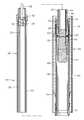
- FIG. 1is a side, cross-sectional view of an exemplary wellbore with a breached casing and having a patch assembly and setting tool being run in.
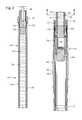
- FIG. 2is an enlarged side, cross-sectional view of the patch assembly and setting tool shown in FIG. 1 in a run-in configuration.
- FIG. 3is an axial cross-section taken along lines 3 - 3 in FIG. 2 .
- FIG. 4is a side, cross-sectional view of the patch assembly and setting tool shown in FIG. 2 , prior to the patch assembly being set.
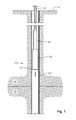
- FIG. 5is a side, cross-sectional view of the patch assembly and setting tool shown in FIGS. 2 and 4 , during setting of the patch assembly.
- FIG. 6is a side, cross-sectional view of the patch assembly and setting tool shown in FIGS. 2 , 4 and 5 , now with the patch assembly fully set in place.
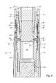
- FIG. 7is an enlarged side, cross-sectional view of portions of the patch assembly following removal of the setting tool.
- FIG. 1depicts an exemplary wellbore 10 which has been drilled from the surface 12 through the earth 14 down to a hydrocarbon-bearing formation 16 .
- the wellbore 10has been lined with metallic casing 18 of a type known in the art.
- the casing 18has a breach within it, depicted at 20 , which it is desired to patch.
- the term “breach”, as used herein,need not require an actual opening within the casing 18 , but may also refer to an area of weakness which it is desired to patch.
- a wireline, e-line, or similar running string 22is disposed into the wellbore 10 from the surface 12 .
- a setting tool 24is secured to the running string 22 and is releasably secured to a patch assembly 26 which is constructed in accordance with the present invention.
- the setting tool 24which is better appreciated with reference to FIGS. 2 and 3 , includes an elongated heating barrel 28 which defines an interior chamber 30 .
- the upper axial end of the heating barrel 28is affixed to a top sub 32 .
- Above the top sub 32is an arrangement (not shown) known in the art by which the setting tool 24 is secured to the running string 22 .
- a top plug 34is threadedly secured within the top sub 32 .
- a flow port 36is formed through the top plug 34 and is in fluid communication with fluid injection conduit 38 .
- the fluid injection conduit 38extends from the setting tool 24 to a fluid supply which may be in the form of a high-pressure cylinder (not shown) which is attached to the setting tool 24 having an electrically-operated valve which can be opened from the surface 12 .
- a fluid supplywhich may be in the form of a high-pressure cylinder (not shown) which is attached to the setting tool 24 having an electrically-operated valve which can be opened from the surface 12 .
- Cylinders and valves of this typeare well known in the art.
- Other suitable fluid supply arrangements known in the artmay be used as well.
- the fluid provided by the fluid supplyis nitrogen.
- a fill port 44is disposed through the heating barrel 28 and is closed off by removable plug 46 .
- Eutectic material 47is located within the chamber 30 of the heating barrel 28 , and may be flowed into the chamber 30 in its liquid state via the fill port 44 .
- the eutectic materialcomprises eutectic salts.
- Eutectic saltsare sometimes referred to as “phase changing salts” or phase-changing material.
- Eutectic materialsare characterized by forming very regular crystalline molecular lattices in the solid phase.
- Eutectic materialsare chemical compounds that have the physical characteristic of changing phase (melting or solidifying) at varying temperatures: melting at one temperature and solidifying at another. The temperature range between which the melting or solidification occurs is dependent on the composition of the eutectic material.
- the eutectic melting pointis lower than the melting temperature of any of the composite compounds.
- the composite materialis approximately twice as dense as water, weighing approximately 120 pounds per cubic foot.
- Salt-based eutectic materialcan be formulated to work at temperatures as low as 30° F. and as high as 1100° F.
- Metal-based eutectic materialscan operate at temperatures exceeding 1900° F.
- the salt compoundis a sodium nitrate and potassium nitrate mixture which melts at approximately 610° F. and solidifies at approximately 500° F.
- the liquid salt compoundexists as a superheated fluid, and when it changes phase, it does so very rapidly, typically in just minutes.
- the salt compoundhas a compressive strength of approximately 2700 psi.
- a number of axial grooves 48are formed in the outer radial surface of the heating barrel 28 , and heating elements 50 are disposed within the grooves 48 .
- the heating elements 50are preferably shaped to reside within the grooves 48 and are preferably supplied with electric power for heating via wires (not shown) that are incorporated into the running string 22 .
- the heating element 50may be energized to heat the barrel 28 to a temperature that is sufficient to maintain the eutectic material 47 in its liquid state.
- the volume of eutectic material 47 within the barrel 28is bounded at its upper end by a floating piston 52 and at its lower end by a lower piston 54 .
- the floating piston 52is slidably moveable within the chamber 30 and, when the chamber 30 is filled with eutectic material 47 , the floating piston 52 is proximate to or in abutting contact with the top plug 34 .
- the lower piston 54is located radially within the lower end of the barrel 28 and a fill mandrel 56 , as best shown in FIG. 4 .
- the fill mandrel 56is affixed to the lower end of the heating barrel 28 by threading 58 .
- Fluid flow ports 60are disposed through the fill mandrel 56 and are initially closed off by the lower piston 54 , which is retained in place by frangible shear pins 62 .
- a bottom plug 64is threaded into the lower end of the fill mandrel 56 and represents the lower end of the setting tool 28 .
- a collapsible chamber 66is defined between the lower piston 54 and the bottom plug 64 .
- the patch assembly 26includes a tubular patch sub 68 which preferably has a top sub 70 affixed to its upper end and a bottom sub 72 affixed to its lower end.
- Shear members 74releasably affix the top sub 70 to the fill mandrel 56 , thereby releasably securing the patch assembly 26 to the setting tool 24 .
- An annular, flexible boot 76radially surrounds the patch sub 68 , and a cavity 78 is defined between the patch sub 68 and the boot 76 .
- the boot 76is preferably formed of a high-temperature tolerant material that is capable of containing the eutectic material 47 in its liquid, high-temperature state. In a current embodiment, the boot 76 is formed of silicone-coated KEVLAR® fiber. The boot 76 is secured to the sub 68 at its upper and lower axial ends so that the cavity 78 is completely enclosed.
- Flow ports 80are disposed through the patch sub 68 and are aligned with the flow ports 60 of the fill mandrel 56 when the casing patch assembly 26 is affixed to the setting tool 24 .
- a slidable sleeve 82is located within the upper end of the patch sub 68 and is moveable between a lower position, shown in FIG. 4 , and an upper position, shown in FIG. 6 .
- Openings 84are disposed through the sleeve 82 and, when the sleeve 82 is in the lower position, these openings 84 are aligned with the flow ports 60 and 80 .
- Collets 86extend axially upwardly from the sleeve 82 and are shaped and sized to engage a complimentary shoulder 88 that is formed on the outer radial surface of the fill mandrel 56 .
- the patch assembly 26 and setting tool 24are lowered into the wellbore 10 by the running string 22 until the patch assembly 26 is positioned adjacent the breach 20 .
- fluidis flowed into the setting tool 24 via the fluid conduit 28 .
- the fluidflows through the flow port 36 of the top sub 34 and urges the floating piston 36 axially downwardly within the chamber 30 of the heating barrel 28 .
- the lower piston 54will be urged downwardly as a result of fluid pressure within the barrel 28 , shearing frangible pins 62 and uncovering ports 60 .
- the liquid eutectic material 47 that fills the chamber 36 of the heating barrel 28can now flow through aligned ports and openings, 60 , 84 and 80 to enter the cavity 78 within the boot 76 .
- FIG. 5illustrates the setting tool 24 in an intermediate condition wherein the floating piston 54 has been moved partially downward within the chamber 30 , and the lower piston 54 having been moved downwardly, collapsing chamber 66 , so as to be adjacent the bottom plug 64 .
- FIG. 6illustrates a further point in the setting process wherein the liquid eutectic material 47 has been flowed out of the chamber 30 and into the boot 76 .
- the floating piston 52has descended within the chamber 30 until it comes into contact with the lower piston 54 . After the liquid eutectic material 47 has been flowed out of the heating barrel 28 and into the boot 76 , the material 47 will cool and solidify.
- FIG. 7shows details of the upper end of the casing patch assembly 26 after it has been set and the setting tool 24 has been removed. As can be seen in FIG.
- the openings 84 in the sleeve 82are moved above the ports 80 in the patch sub 68 , thereby closing the ports 80 against fluid flow therethrough.
- the outwardly protruding portions of the collets 86will retract into an annular recess 90 that is formed on the interior radial surface of the top sub 70 . This will release the engagement between the collets 86 and shoulder 88 , allowing the setting tool 24 to be completely freed from the casing patch assembly 26 .
- An exemplary patching systemincludes a patch assembly 26 and a setting tool 24 .
- the exemplary patch assembly 26includes a tubular patch sub 68 and a flexible boot 76 which radially surrounds the patch sub 68 to form a cavity 78 therein.
- the exemplary setting toolincludes a heating barrel 28 which contains eutectic material at a temperature sufficient to maintain the eutectic material 47 in a liquid state.
- a flow mechanismis provided to selectively flow eutectic material from the heating barrel 28 to the cavity 78 of the patch assembly 26 .
- the flow mechanismis provided by a flow path (aligned flow ports 60 , 84 , 80 ) through which the liquid eutectic material can flow from the heating barrel 28 to the boot 76 .
- the flow mechanismincludes a piston, such as floating piston 52 , which is moveable within the chamber 36 of the heating barrel 28 to urge the eutectic material 47 out of the chamber 36 and into the boot 76 .
- a patch assembly 26 and setting tool 24are disposed into a wellbore 10 until the patch assembly is located adjacent a section of tubular that it is desired to patch.
- the patch assembly 26is then set by flowing liquid eutectic material along a flow path from the setting tool 24 to the cavity 78 .
- the eutectic materialwill then cool within the cavity 78 and solidify.
- the setting tool 24is detached from the patch assembly 26 and removed from the wellbore 10 .
- the flow pathis closed against fluid flow as the setting tool 24 is detached and removed.
Landscapes
- Life Sciences & Earth Sciences (AREA)
- Engineering & Computer Science (AREA)
- Geology (AREA)
- Mining & Mineral Resources (AREA)
- Physics & Mathematics (AREA)
- Environmental & Geological Engineering (AREA)
- Fluid Mechanics (AREA)
- General Life Sciences & Earth Sciences (AREA)
- Geochemistry & Mineralogy (AREA)
- Actuator (AREA)
Abstract
Description
Claims (18)
Priority Applications (2)
| Application Number | Priority Date | Filing Date | Title |
|---|---|---|---|
| US13/152,628US8151895B1 (en) | 2006-02-17 | 2011-06-03 | Eutectic salt inflated wellbore tubular patch |
| CA2778745ACA2778745C (en) | 2011-06-03 | 2012-05-31 | Eutectic salt inflated wellbore tubular patch |
Applications Claiming Priority (4)
| Application Number | Priority Date | Filing Date | Title |
|---|---|---|---|
| US77468806P | 2006-02-17 | 2006-02-17 | |
| US11/676,191US7673692B2 (en) | 2006-02-17 | 2007-02-16 | Eutectic material-based seal element for packers |
| US12/714,282US7997337B2 (en) | 2006-02-17 | 2010-02-26 | Eutectic material-based seal element for packers |
| US13/152,628US8151895B1 (en) | 2006-02-17 | 2011-06-03 | Eutectic salt inflated wellbore tubular patch |
Related Parent Applications (1)
| Application Number | Title | Priority Date | Filing Date |
|---|---|---|---|
| US12/714,282Continuation-In-PartUS7997337B2 (en) | 2006-02-17 | 2010-02-26 | Eutectic material-based seal element for packers |
Publications (1)
| Publication Number | Publication Date |
|---|---|
| US8151895B1true US8151895B1 (en) | 2012-04-10 |
Family
ID=45921980
Family Applications (1)
| Application Number | Title | Priority Date | Filing Date |
|---|---|---|---|
| US13/152,628Expired - Fee RelatedUS8151895B1 (en) | 2006-02-17 | 2011-06-03 | Eutectic salt inflated wellbore tubular patch |
Country Status (1)
| Country | Link |
|---|---|
| US (1) | US8151895B1 (en) |
Cited By (11)
| Publication number | Priority date | Publication date | Assignee | Title |
|---|---|---|---|---|
| US8857513B2 (en) | 2012-01-20 | 2014-10-14 | Baker Hughes Incorporated | Refracturing method for plug and perforate wells |
| US9109425B2 (en) | 2012-08-17 | 2015-08-18 | Baker Hughes Incorporated | Removable fracturing plug of particulate material housed in a sheath set by relative end movement of the sheath |
| US9255461B2 (en) | 2012-08-17 | 2016-02-09 | Baker Hughes Incorporated | Removable fracturing plug of particulate material housed in a sheath set by expansion of a passage through the sheath |
| GB2529275A (en)* | 2014-08-15 | 2016-02-17 | Bisn Oil Tools Ltd | Methods and apparatus for use in oil and gas well completion |
| WO2016049424A1 (en)* | 2014-09-25 | 2016-03-31 | Schlumberger Canada Limited | Downhole sealing tool |
| US10018010B2 (en) | 2014-01-24 | 2018-07-10 | Baker Hughes, A Ge Company, Llc | Disintegrating agglomerated sand frack plug |
| US10072477B2 (en) | 2014-12-02 | 2018-09-11 | Schlumberger Technology Corporation | Methods of deployment for eutectic isolation tools to ensure wellbore plugs |
| CN109751009A (en)* | 2016-09-06 | 2019-05-14 | 中国石油化工股份有限公司 | One kind can hot-washing wax remover packer repeatedly |
| US11525329B2 (en)* | 2012-12-20 | 2022-12-13 | BiSN Tec. Ltd. | Apparatus for use in well abandonment |
| US20240117703A1 (en)* | 2021-03-19 | 2024-04-11 | Interwell P&A As | Method for providing a permanent barrier in a well |
| US12312904B2 (en)* | 2016-05-24 | 2025-05-27 | Bisn Tec Ltd. | Down-hole chemical heater and methods of operating such |
Citations (12)
| Publication number | Priority date | Publication date | Assignee | Title |
|---|---|---|---|---|
| US3314479A (en) | 1965-01-25 | 1967-04-18 | Otis J Mccullough | Bridging plug |
| US4573537A (en) | 1981-05-07 | 1986-03-04 | L'garde, Inc. | Casing packer |
| US4923007A (en) | 1988-11-15 | 1990-05-08 | Tam International | Inflatable packer with improved reinforcing members |
| US5819846A (en) | 1996-10-01 | 1998-10-13 | Bolt, Jr.; Donald B. | Bridge plug |
| US5829524A (en) | 1996-05-07 | 1998-11-03 | Baker Hughes Incorporated | High pressure casing patch |
| US5833001A (en) | 1996-12-13 | 1998-11-10 | Schlumberger Technology Corporation | Sealing well casings |
| US20020056553A1 (en) | 2000-06-01 | 2002-05-16 | Duhon Mark C. | Expandable elements |
| US6474414B1 (en) | 2000-03-09 | 2002-11-05 | Texaco, Inc. | Plug for tubulars |
| US20070051514A1 (en) | 2005-09-08 | 2007-03-08 | La Rovere Thomas A | Method and apparatus for well casing repair and plugging utilizing molten metal |
| US7234533B2 (en) | 2003-10-03 | 2007-06-26 | Schlumberger Technology Corporation | Well packer having an energized sealing element and associated method |
| US20070199693A1 (en)* | 2006-02-17 | 2007-08-30 | Innicor Subsurface Technologies Inc | Eutectic material-based seal element for packers |
| US7290609B2 (en) | 2004-08-20 | 2007-11-06 | Cinaruco International S.A. Calle Aguilino De La Guardia | Subterranean well secondary plugging tool for repair of a first plug |
- 2011
- 2011-06-03USUS13/152,628patent/US8151895B1/ennot_activeExpired - Fee Related
Patent Citations (15)
| Publication number | Priority date | Publication date | Assignee | Title |
|---|---|---|---|---|
| US3314479A (en) | 1965-01-25 | 1967-04-18 | Otis J Mccullough | Bridging plug |
| US4573537A (en) | 1981-05-07 | 1986-03-04 | L'garde, Inc. | Casing packer |
| US4923007A (en) | 1988-11-15 | 1990-05-08 | Tam International | Inflatable packer with improved reinforcing members |
| US5829524A (en) | 1996-05-07 | 1998-11-03 | Baker Hughes Incorporated | High pressure casing patch |
| US5819846A (en) | 1996-10-01 | 1998-10-13 | Bolt, Jr.; Donald B. | Bridge plug |
| US5833001A (en) | 1996-12-13 | 1998-11-10 | Schlumberger Technology Corporation | Sealing well casings |
| US6474414B1 (en) | 2000-03-09 | 2002-11-05 | Texaco, Inc. | Plug for tubulars |
| US20020056553A1 (en) | 2000-06-01 | 2002-05-16 | Duhon Mark C. | Expandable elements |
| US7455104B2 (en)* | 2000-06-01 | 2008-11-25 | Schlumberger Technology Corporation | Expandable elements |
| US7234533B2 (en) | 2003-10-03 | 2007-06-26 | Schlumberger Technology Corporation | Well packer having an energized sealing element and associated method |
| US7290609B2 (en) | 2004-08-20 | 2007-11-06 | Cinaruco International S.A. Calle Aguilino De La Guardia | Subterranean well secondary plugging tool for repair of a first plug |
| US20070051514A1 (en) | 2005-09-08 | 2007-03-08 | La Rovere Thomas A | Method and apparatus for well casing repair and plugging utilizing molten metal |
| US20070199693A1 (en)* | 2006-02-17 | 2007-08-30 | Innicor Subsurface Technologies Inc | Eutectic material-based seal element for packers |
| US20100018694A1 (en)* | 2006-02-17 | 2010-01-28 | Bj Tool Services Ltd. | Eutectic material-based seal element for packers |
| US7673692B2 (en) | 2006-02-17 | 2010-03-09 | Bj Tool Services Ltd. | Eutectic material-based seal element for packers |
Cited By (17)
| Publication number | Priority date | Publication date | Assignee | Title |
|---|---|---|---|---|
| US8857513B2 (en) | 2012-01-20 | 2014-10-14 | Baker Hughes Incorporated | Refracturing method for plug and perforate wells |
| US9109425B2 (en) | 2012-08-17 | 2015-08-18 | Baker Hughes Incorporated | Removable fracturing plug of particulate material housed in a sheath set by relative end movement of the sheath |
| US9255461B2 (en) | 2012-08-17 | 2016-02-09 | Baker Hughes Incorporated | Removable fracturing plug of particulate material housed in a sheath set by expansion of a passage through the sheath |
| US11525329B2 (en)* | 2012-12-20 | 2022-12-13 | BiSN Tec. Ltd. | Apparatus for use in well abandonment |
| US10018010B2 (en) | 2014-01-24 | 2018-07-10 | Baker Hughes, A Ge Company, Llc | Disintegrating agglomerated sand frack plug |
| GB2529275B (en)* | 2014-08-15 | 2021-07-21 | Bisn Tec Ltd | Methods and apparatus for use in oil and gas well completion |
| GB2529275A (en)* | 2014-08-15 | 2016-02-17 | Bisn Oil Tools Ltd | Methods and apparatus for use in oil and gas well completion |
| US11085265B2 (en) | 2014-09-25 | 2021-08-10 | Schlumberger Technology Corporation | Downhole sealing tool |
| GB2544695B (en)* | 2014-09-25 | 2021-02-17 | Schlumberger Technology Bv | Downhole sealing tool |
| GB2544695A (en)* | 2014-09-25 | 2017-05-24 | Schlumberger Technology Bv | Downhole sealing tool |
| WO2016049424A1 (en)* | 2014-09-25 | 2016-03-31 | Schlumberger Canada Limited | Downhole sealing tool |
| US10072477B2 (en) | 2014-12-02 | 2018-09-11 | Schlumberger Technology Corporation | Methods of deployment for eutectic isolation tools to ensure wellbore plugs |
| US12312904B2 (en)* | 2016-05-24 | 2025-05-27 | Bisn Tec Ltd. | Down-hole chemical heater and methods of operating such |
| CN109751009A (en)* | 2016-09-06 | 2019-05-14 | 中国石油化工股份有限公司 | One kind can hot-washing wax remover packer repeatedly |
| CN109751009B (en)* | 2016-09-06 | 2021-02-12 | 中国石油化工股份有限公司 | Repeated hot-washing paraffin removal packer |
| US20240117703A1 (en)* | 2021-03-19 | 2024-04-11 | Interwell P&A As | Method for providing a permanent barrier in a well |
| US12129736B2 (en)* | 2021-03-19 | 2024-10-29 | Interwell P&A As | Method for providing a permanent barrier in a well |
Similar Documents
| Publication | Publication Date | Title |
|---|---|---|
| US8151895B1 (en) | Eutectic salt inflated wellbore tubular patch | |
| US11536111B2 (en) | Downhole tool deployment assembly with improved heater removability and methods of employing such | |
| US12084942B2 (en) | Downhole well tools and methods of using such | |
| US11867020B2 (en) | Expandable eutectic alloy based downhole tool and methods of deploying such | |
| US4671356A (en) | Through tubing bridge plug and method of installation | |
| US7963340B2 (en) | Method for disintegrating a barrier in a well isolation device | |
| US20040251025A1 (en) | Single-direction cementing plug | |
| CA1294869C (en) | Permanent anchor for use with through tubing bridge plug | |
| CA2419643A1 (en) | Method, apparatus and system for selective release of cementing plugs | |
| US11851959B2 (en) | Method and apparatus for the exact placement of resin and cement plugs | |
| WO2015139111A1 (en) | Degradable wellbore tool and method | |
| EP3940194B1 (en) | Casing annulus leakage repair method and system | |
| CA3081968C (en) | Downhole tool with tethered ball | |
| CA2880558A1 (en) | Expandable liner | |
| US20210277735A1 (en) | Tandem releasable bridge plug system and method for setting such tandem releasable bridge plugs | |
| EP3631150B1 (en) | A downhole tool deployment assembly with improved heater removability and methods of employing such | |
| CA2778745C (en) | Eutectic salt inflated wellbore tubular patch | |
| US9359857B2 (en) | Setting assembly and method thereof | |
| US20240295157A1 (en) | Annular barrier | |
| EP4359639B1 (en) | Downhole well tool and method for permanently sealing a downhole well | |
| CN112443289B (en) | Packing type stage cementing device | |
| GB2608269A (en) | An expandable eutectic alloy based downhole tool and methods of deploying such | |
| CA1135683A (en) | Pump in core breaker carrier |
Legal Events
| Date | Code | Title | Description |
|---|---|---|---|
| AS | Assignment | Owner name:BAKER HUGHES INCORPORATED, TEXAS Free format text:ASSIGNMENT OF ASSIGNORS INTEREST;ASSIGNOR:KUNZ, DALE IAN;REEL/FRAME:026637/0960 Effective date:20110707 | |
| ZAAA | Notice of allowance and fees due | Free format text:ORIGINAL CODE: NOA | |
| ZAAB | Notice of allowance mailed | Free format text:ORIGINAL CODE: MN/=. | |
| STCF | Information on status: patent grant | Free format text:PATENTED CASE | |
| FEPP | Fee payment procedure | Free format text:PAYOR NUMBER ASSIGNED (ORIGINAL EVENT CODE: ASPN); ENTITY STATUS OF PATENT OWNER: LARGE ENTITY | |
| REMI | Maintenance fee reminder mailed | ||
| FPAY | Fee payment | Year of fee payment:4 | |
| SULP | Surcharge for late payment | ||
| MAFP | Maintenance fee payment | Free format text:PAYMENT OF MAINTENANCE FEE, 8TH YEAR, LARGE ENTITY (ORIGINAL EVENT CODE: M1552); ENTITY STATUS OF PATENT OWNER: LARGE ENTITY Year of fee payment:8 | |
| AS | Assignment | Owner name:BAKER HUGHES, A GE COMPANY, LLC, TEXAS Free format text:CHANGE OF NAME;ASSIGNOR:BAKER HUGHES INCORPORATED;REEL/FRAME:059497/0467 Effective date:20170703 | |
| AS | Assignment | Owner name:BAKER HUGHES HOLDINGS LLC, TEXAS Free format text:CHANGE OF NAME;ASSIGNOR:BAKER HUGHES, A GE COMPANY, LLC;REEL/FRAME:059620/0651 Effective date:20200413 | |
| FEPP | Fee payment procedure | Free format text:MAINTENANCE FEE REMINDER MAILED (ORIGINAL EVENT CODE: REM.); ENTITY STATUS OF PATENT OWNER: LARGE ENTITY | |
| LAPS | Lapse for failure to pay maintenance fees | Free format text:PATENT EXPIRED FOR FAILURE TO PAY MAINTENANCE FEES (ORIGINAL EVENT CODE: EXP.); ENTITY STATUS OF PATENT OWNER: LARGE ENTITY | |
| STCH | Information on status: patent discontinuation | Free format text:PATENT EXPIRED DUE TO NONPAYMENT OF MAINTENANCE FEES UNDER 37 CFR 1.362 | |
| FP | Lapsed due to failure to pay maintenance fee | Effective date:20240410 |