US8151409B2 - Vacuum cleaner - Google Patents
Vacuum cleanerDownload PDFInfo
- Publication number
- US8151409B2 US8151409B2US12/710,585US71058510AUS8151409B2US 8151409 B2US8151409 B2US 8151409B2US 71058510 AUS71058510 AUS 71058510AUS 8151409 B2US8151409 B2US 8151409B2
- Authority
- US
- United States
- Prior art keywords
- lever
- dust collection
- gear
- collection device
- dust
- Prior art date
- Legal status (The legal status is an assumption and is not a legal conclusion. Google has not performed a legal analysis and makes no representation as to the accuracy of the status listed.)
- Expired - Fee Related, expires
Links
Images


Classifications
- A—HUMAN NECESSITIES
- A47—FURNITURE; DOMESTIC ARTICLES OR APPLIANCES; COFFEE MILLS; SPICE MILLS; SUCTION CLEANERS IN GENERAL
- A47L—DOMESTIC WASHING OR CLEANING; SUCTION CLEANERS IN GENERAL
- A47L9/00—Details or accessories of suction cleaners, e.g. mechanical means for controlling the suction or for effecting pulsating action; Storing devices specially adapted to suction cleaners or parts thereof; Carrying-vehicles specially adapted for suction cleaners
- A47L9/10—Filters; Dust separators; Dust removal; Automatic exchange of filters
- A47L9/106—Dust removal
- A47L9/108—Dust compression means
- A—HUMAN NECESSITIES
- A47—FURNITURE; DOMESTIC ARTICLES OR APPLIANCES; COFFEE MILLS; SPICE MILLS; SUCTION CLEANERS IN GENERAL
- A47L—DOMESTIC WASHING OR CLEANING; SUCTION CLEANERS IN GENERAL
- A47L9/00—Details or accessories of suction cleaners, e.g. mechanical means for controlling the suction or for effecting pulsating action; Storing devices specially adapted to suction cleaners or parts thereof; Carrying-vehicles specially adapted for suction cleaners
- A47L9/10—Filters; Dust separators; Dust removal; Automatic exchange of filters
- A47L9/16—Arrangement or disposition of cyclones or other devices with centrifugal action
- A47L9/1691—Mounting or coupling means for cyclonic chamber or dust receptacles
Definitions
- a vacuum cleaneris disclosed herein.
- Vacuum cleanersare known. However, they suffer from various disadvantages.
- FIG. 1is a front, exploded perspective view of a vacuum cleaner according to an embodiment
- FIG. 2is a sectional view of a dust separation device and a dust collection device according to the embodiment of FIG. 1 ;
- FIG. 3is a perspective view of the dust collection device according to the embodiment of FIG. 1 ;
- FIG. 4is a bottom perspective view of the dust collection device of FIG. 3 ;
- FIG. 5is an exploded perspective view of the dust collection device of FIG. 3 ;
- FIG. 6is a perspective view of a lever of the dust collection device of FIG. 3 ;
- FIG. 7is a bottom perspective view of the dust collection device of FIG. 3 from which the lever has been removed;
- FIGS. 8 and 9are views of a state in which the lever of the dust collection device of FIG. 3 is disposed at a first position
- FIGS. 10 and 11are views of a state in which the lever of the dust collection device of FIG. 3 is disposed at a second position
- FIGS. 12 and 13are views of a state in which the lever of the dust collection device of FIG. 3 is disposed at a third position;
- FIG. 14is a sectional view taken along line XIV-XIV of FIG. 12 ;
- FIGS. 15 and 16are views of a dust collection device according to another embodiment
- FIGS. 17 and 18are views of a main body and a dust collection device according to another embodiment.
- FIGS. 19 and 20are views illustrating an operation of a lever according to the embodiment of FIGS. 17-18 .
- vacuum cleanersare devices that suck in air containing dust using vacuum pressure generated by a suction motor installed inside a main body to filter the dust in the main body.
- a suction motorinstalled inside a main body to filter the dust in the main body.
- air sucked in through a suction nozzleshould smoothly flow into the main body.
- dustshould be easily separated from air containing the dust.
- vacuum cleanershave included a dust separation device and a dust collection device.
- the dust separation devicesucks air containing dust to generate a rotating flow.
- the dust collection devicecollects the dust separated by the dust separation device.
- the dust collection devicemay be detachably coupled to a main body of a vacuum cleaner, and a user may separate the dust collection device from the main body to separate the dust filled within the dust collection device. Also, to increase dust capacity within the dust collection device, a technology for compressing dust within the dust collection device has been applied to the vacuum cleaner.
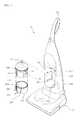
- FIG. 1is a front, exploded perspective view of a vacuum cleaner according to an embodiment
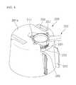
- FIG. 2is a sectional view of a dust separation device and a dust collection device according to the embodiment of FIG. 1
- a vacuum cleaner 10may include a main body 100 that defines an outer appearance thereof, and a suction nozzle 120 , which may be disposed at lower portion of the main body 100 , that sucks air containing foreign substances from a surface or floor to be cleaned.
- the main body 100may include a driving part (not shown) that provides a suction force.
- a handle 101configured to be grasped by a user to move the main body 100 or the suction nozzle 120 may be disposed on an upper portion of the main body 100 .
- the vacuum cleaner 10may include a dust separation device 150 that separates dust from the sucked air.
- the dust separation device 150may be detachably provided to the main body 100 and may have an open lower portion.
- the dust separation device 150may include a body part 151 , which may have an approximately cylindrical shape, an air suction part 154 , which may be disposed at a side of the body part 151 , that suck in the air, and an air exhaust part 155 that exhausts the air from which the dust is separated.
- the dust separation device 150may further include a filter member 153 configured to filter the dust from the sucked air.
- a receiving end 151 aconfigured to be coupled to a dust collection device 200 may be disposed at a lower end of the body part 151 .
- the dust collection device 200in which the dust separated by the dust separation device 150 may be stored, may be detachably disposed at a lower portion of the dust separation device 150 .
- the dust collection device 200may include a dust collection case 201 that defines an outer appearance thereof and a dust collection cover 202 that covers an open top surface of the dust collection case 201 .
- a dust inlet 202 athrough which the dust may drop or fall from the dust separation device 150 into the dust collection device 200 , may be disposed in the dust collection cover 202 .
- An operable lever 220 for detachment of the dust separation device 150 and for compression of the dustmay be disposed at a lower portion of the dust collection device 200 .
- the lever 220may be rotated in a first direction or a second direction.
- a receiving part 201 ain which the receiving end 151 a of the dust separation device 151 a may be received, may be disposed at an upper end of the dust collection case 201 .
- the receiving part 201 amay have, for example, a U-shape so that the receiving end 151 a may be inserted into the receiving part 201 a from an upper side.
- the dust collection device 200When the dust separation device 150 and the dust collection device 200 are coupled to each other, the dust collection device 200 may be moved upwardly, and the receiving part 201 a coupled to a lower portion of the receiving end 151 a . On the other hand, when the dust separation device 150 is separated from the dust collection device 200 , the dust collection device 200 may be moved downwardly, and the receiving part 201 a separated from the receiving end 151 a.
- a mounting space 102in which the dust separation device 150 and the dust collection device 200 may be mounted, may be defined in the main body 100 .
- a front surface of the main body 100may be backwardly depressed to form the mounting space 102 .
- a seat surface 103on which the dust collection device 200 may be seated, may be disposed at a lower side of the mounting space 102 .
- One or more guide protrusion(s) 104may be disposed on the seat surface 103 to guide the dust collection device 200 when the dust collection device 200 is slidably mounted to the mounting space 102 .
- An air inlet tube 105which may communicate with the air suction part 154
- an air outlet tube 106which may communicate with the air exhaust part 155
- the air inlet tube 105 and the air outlet tube 106may extend downwardly from the main body 100 . Air flowing along the air inlet tube 105 may be sucked into the dust separation device 150 through the air suction part 154 . The air exhausted from the air exhaust part 155 may flow toward the main body 100 through the air outlet tube 106 .
- FIG. 3is a perspective view of the dust collection device according to the embodiment of FIG. 1 .
- FIG. 4is a bottom perspective view of the dust collection device of FIG. 3
- FIG. 5is an exploded perspective view of the dust collection device of FIG. 3 .
- the dust collection device 200may include the dust collection case 201 , a first compression member 211 , a second compression member 212 , and a grasp part 203 configured to be grasped by a user.
- a storage space 201 bmay be defined in the dust collection case 201 .
- the first and second compression members 211 and 212may be disposed inside of the dust collection case 201 to compress the dust stored in the storage space 201 b .
- the grasp part 203may be disposed on an outside of the dust collection case 201 .
- the first compression member 211may be fixed to an inside of the dust collection case 201 . Further, the first compression member 211 may be integrated with the dust collection case 201 .
- the second compression member 212may be rotatably disposed within the dust collection case 201 .
- One or more compression protrusion(s) 212 amay protrude from the second compression member 212 to easily compress the dust.
- a rotation shaft 213which may provide a rotational center of the second compression member 212 , may be disposed in the dust collection device 200 .
- the second compression member 212 and the rotation shaft 213may be integrally rotated.
- the rotation shaft 213may include a shaft upper portion 213 a , which may extend from the second compression member 212 , and a shaft lower portion 213 b , which may extend downwardly from the shaft upper portion 213 a .
- the shaft upper portion 213 amay have a diameter greater than a diameter of the shaft lower portion 213 b.
- a rotation guide 215 that guides rotation of the rotation shaft 213may be disposed in the dust collection device 200 .
- the rotation guide 215may protrude upwardly from a bottom surface of the dust collection case 201 .
- the shaft lower portion 213 bmay be rotatably received into the rotation guide 215 .
- the operable lever 220 configured to rotate of the rotation shaft 213 and the second compression member 212may be disposed at a lower portion of the dust collection case 201 .
- the lever 220may include a lever body 221 , a lever handle 222 , which may protrude from a side of the lever body 221 , and a first gear 224 disposed on an upper portion of the lever body 221 .
- the lever handle 222When the lever handle 222 is rotated by a user, the lever body 221 and the first gear 224 may be integrally rotated.
- a second gear 217 and a gear shaft 218may be disposed at or adjacent a side of the first gear 224 .
- the second gear 217 and the gear shaft 218may selectively interlock with the first gear 224 .
- the gear shaft 218may be coupled to a lower portion of the rotation shaft 213 .
- the rotation shaft 213 and the second compression member 212may be rotatable. With this structure, dust within the dust collection case 201 may be compressed.
- a gear ratiomay be defined such that a number of teeth of the first gear 224 may be greater than a number of teeth of the second gear 217 .
- the first gear 224may be rotated at a rotation angle less than one revolution.
- An outer guide surface 223may be provided on an outer surface of the lever body 221 .
- a relative motion between the lever 220 and the dust collection case 201may occur due to the outer guide surface 223 .
- a portion of the lever body 221may be cut away to form the outer guide surface 223 , for example, in a groove shape. Further, the outer guide surface 223 may be inclined in one direction.
- the lever 220may be rotatably coupled to an under surface 201 a of the dust collection case 201 .
- One or more coupling member(s) 207configured to be guided along the outer guide surface 223 may be disposed on an outside of the lever 220 in one or more corresponding coupling member receiving protrusion(s) 208 .
- the coupling member(s) 207may be coupled to the under surface 201 a and seated on the outer guide surface 223 .
- the lever 220may be supported by the coupling member(s) 207 in a state in which the lever 220 is coupled to the dust collection case 201 .
- a stepped portion 209 that limits a left and right rotation range of the lever 220may be disposed on the dust collection case 201 .
- the stepped portion 209may be bent or extend upwardly from the under surface 201 a.
- One or more guide groove(s) 204 that guides mounting of the dust collection device 200may be defined in the under surface 201 a .
- the guide groove 204may be depressed upwardly from the under surface 201 a .
- the guide groove(s) 204may receive the guide protrusion(s) 104 . That is, the mounting of the dust collection device 200 may be guided by the guide groove(s) 204 and the guide protrusion(s) 104 .
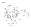
- FIG. 6is a perspective view of a lever of the dust collection device of FIG. 3 .
- FIG. 7is a bottom perspective view of the dust collection device of FIG. 3 in which the lever has been removed.
- the lever 220may include the lever body 221 , which may have an approximately cylindrical shape, the first gear 224 disposed on the upper portion of the lever body 221 , and one or more protrusion(s) 225 disposed on an inside of the first gear 224 .
- the outer guide surface 223 inclined upwardly from the under surface of the lever body 221may be disposed on the lever body 221 .
- the coupling member(s) 207may be moved along the outer guide surface 223 .
- the first gear 224may include a portion having gear teeth 224 a configured to interlock with the second gear 217 disposed adjacent thereto and a cylindrical portion 224 b having a smooth surface without gear teeth. That is, the gear teeth may be disposed on a portion of an outer circumferential surface of the first gear 224 to interlock with the second gear 217 . On the other hand, gear teeth may not be provided on a remaining portion of the outer circumferential surface of the first gear 224 .
- a downwardly depressed portion 224 cmay be defined inside of the first gear 224 .
- One or more protrusion guide(s) 225 that protrudes upwardlymay be disposed on or in the depressed portion 224 c.
- a plurality of protrusion guides 225may be provided spaced a predetermined distance from an inside of the gear teeth 224 a and the depressed portion 224 c .
- the plurality of protrusion guides 225may be spaced apart from each other and may have a rounded shape.
- Inner guide surfaces 226may be disposed between the plurality of protrusion guides 225 . When the lever 220 is rotated, the inner guide surfaces 226 may be guided by the dust collection case 201 . The inner guide surfaces 226 may be spaced apart from each other. Further, each of the inner guide surfaces 226 may have an approximately rounded shape on the whole.
- each inner guide surface 226may include a flat surface 226 a that extends parallel to a bottom surface of the depressed portion 224 c and an inclined surface 226 b that extends at an incline from the flat surface 226 a toward a respective protrusion guide 225 .
- the flat surface 226 amay protrude at a height less than that of the respective protrusion guide 225
- the inclined surface 226 bmay extend upward at an incline from the flat surface 226 a toward the respective protrusion guide 225 .
- a lever seat part 205on which the lever may be seated, may be disposed on the under surface 201 a of the dust collection case 201 .
- the lever seat part 205may be depressed upwardly from the under surface 201 a of the dust collection case 201 .
- a portion corresponding to a height difference between the under surface 201 a and the lever seat part 205may be defined as the stepped portion 209 .
- a plurality of stepped portions 209may be provided. That is, a stepped portion may be provided on both sides of the lever seat part 205 , respectively.
- a guide part 230 that guides rotation of the lever 220may be disposed on the lever seat part 205 .
- the guide part 230may protrude downwardly from the lever seat part 205 .
- the guide part 230may include a first protrusion 231 that protrudes from the lever seat part 205 by a predetermined height, a second protrusion 232 that protrudes upwardly from the first protrusion 231 , and an inclined portion 233 that extends upwardly at an incline from the first protrusion 231 .
- the first protrusion 231 and the second protrusion 232may have circular column shapes, respectively.
- the second protrusion 232may extend upwardly from an upper end of the first protrusion 231 .
- the second protrusion 232may have a diameter less than a diameter of the first protrusion 231 .
- a plurality of inclined portion 233may be provided.
- the plurality of inclined portions 233may be spaced apart from each other and may be disposed on an outside of the second protrusion 232 .
- the plurality of inclined portions 233may be disposed at a position corresponding to the plurality of inclined surfaces 226 b of the lever 220 . When the lever 220 is rotated, the plurality of inclined surfaces 226 b may be moved along the plurality of inclined portions 233 .
- a gear coupling part 205 ato which the second gear 217 may be coupled, may be disposed on a side of the guide part 230 .
- the gear coupling part 205 amay have a hole shape depressed from the leaver seat part 205 .
- the gear shaft 218may be inserted into the gear coupling part 205 a and may be coupled to the shaft lower portion 213 b .
- the one or more coupling hole(s) 208to which the one or more coupling member(s) 207 may be coupled, may be provided at a side of the lever seat part 205 .
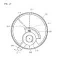
- FIGS. 8 and 9are views of a state in which the lever of the dust collection device of FIG. 3 is disposed at a first position.
- FIGS. 10 and 11are views of a state in which the lever of the dust collection device of FIG. 3 is disposed at a second position.
- FIGS. 12 and 13are views of a state in which the lever of the dust collection device of FIG. 3 is disposed at a third position.
- FIGS. 8 and 13illustrate a rotational operation of the second compression member 212 depending on an operation position of the lever 222 according to the embodiment of FIG. 1 .
- a first positionthe position of the lever handle 222 illustrated in FIG. 8 is referred to as “a first position”.
- the cylindrical portion 224 b of the first gear 224may be disposed adjacent to the second gear 217 , and the gear teeth 224 a of the first gear 224 are not engaged with the second gear 217 .
- the second gear 217does not interlock with the first gear 224 , the second gear 217 is not rotated.
- the protrusion guide 225 of the lever 220may contact the first protrusion 231 .
- the inclined surface 226 bmay contact the inclined portion 233 .
- the under surface 201 a of the dust collection case 201may be moved in a direction near to the lever 220 , and thus, the dust collection case 201 may be moved in a downward direction with respect to the dust separation device 150 . With this process, the coupling between the receiving end 151 a and receiving part 201 a may be released.
- the duct collection device 150may be separated from the dust separation device 150 while the dust collection device 150 is moved downwardly.
- the second gear 217is disposed at a boundary between the cylindrical portion 224 b of the first gear 224 and the gear tooth 224 a . That is, the first gear 224 may be rotated at a position just before the second gear 217 is rotated. In other words, when the lever handle 222 is rotated from the first position of FIG. 8 in a second direction (arrow B in FIG. 10 ), the first gear 224 may be rotated in a counter-clockwise direction. When the lever handle 222 reaches the second position, the first gear 224 may be disposed at a position at which the first gear 224 may interlock with the second gear 217 , that is, a side of the gear teeth 224 a.
- the protrusion guide(s) 225may be moved along the inclined portion(s) 233 .
- the protrusion guide(s) 225may be disposed at a lower end of the inclined portion(s) 233 and spaced from the first protrusion 231 .
- the under surface 201 a of the dust collection case 201may be moved in a direction away from the lever 220 , and the dust collection case 201 moved in an upward direction of the dust separation device 150 .
- the receiving part 201 amay ascend and be coupled to the receiving end 151 a.
- the second compression member 212when the lever 220 is rotated in the second direction (arrow B in FIG. 10 ) and thus, disposed at the second position, the second compression member 212 is not rotated. Also, the dust collection case 201 may be moved upwardly and coupled to the dust separation device 150 .
- the first gear 224may be rotated in a counter-clockwise direction.
- the second gear 217may be rotated in a clockwise direction by interlocking with the first gear 224 .
- the second compression member 212may be integrally rotated with the second gear 217 . With this process, the dust within the dust collection case 201 may be compressed by the first compression member 211 and the second compression member 212 .
- the lever handle 222may be continuously rotated until the lever handle 222 reaches the stepped portion 209 , that is, the lever handle 222 may be disposed at the third position.
- the protrusion guide(s) 225may be moved along the lower end of the inclined portion(s) 233 . That is, the dust collection case 201 , as shown in FIG. 11 , may be maintained in a state in which it is lifted by the lever 220 , and thus, the coupling between the dust collection case 201 and the dust separation device 150 may be maintained.
- the coupling between the dust collection device 150 and the dust separation device 150may be maintained in a state in which the dust collection device 150 is moved upwardly.
- the second gear 217 and the second compression member 212may be rotated in a predetermined direction to compress the dust within the dust collection case 201 .
- the dust collection device 200may be coupled to the dust separation device 150 .
- the dust collection device 200may be separated from the dust separation device 150 without compressing the dust.
- the coupling between the dust collection device 200 and the dust separation device 150may be maintained, and also, the dust may be compressed by the second compression member 212 .
- a usermay operate the lever to selectively realize detachment of the dust collection device and compression of the dust.
- FIG. 14is a view illustrating a coupling relation between a lever and a dust collection case according to another embodiment.
- a dust collection case 201may include a stepped portion 209 that limits a left and right rotation range of a lever handle 222 and a fixing protrusion 209 a that protrudes from the stepped portion 209 toward a lever seat part 205 .
- a hook hole 222 amay be defined in the lever handle 222 .
- the fixing protrusion 209 amay be inserted into and fixed to the hook hole 222 a in a state in which the lever handle 222 is disposed at a side of the stepped portion 209 .
- the fixing protrusion 209 amay have a rounded shape so that the fixing protrusion 209 a may be easily inserted into the hook hole 222 a . Also, the fixing protrusion 209 a may be formed of a material having elasticity, so that the fixing protrusion 209 a may be elastically deformed in a predetermined direction when the fixing protrusion 209 a is inserted into the hook hole 222 a.
- the second compression member 212may be rotated to compress dust within the dust collection case 201 .
- the lever handle 222may be fixed to the stepped portion 209 , that is, the dust collection case 201 .
- a usermay move the lever handle 222 to the third position to compress the dust, and then, the user may apply a larger force to insert the fixing protrusion 209 a into the hook hole 222 a .
- the usermay apply a force to separate the fixing protrusion 209 a from the hook hole 222 a.
- the compressed state of the dustmay be maintained.
- a volume of the stored dustmay be minimized.
- a relatively large amount of dustmay be stored.
- FIGS. 15 and 16are views of a dust collection device according to another embodiment.
- a dust collection device 200may include a first compression member 211 fixed to a dust collection case 201 , a second compression member 212 rotatably disposed at a side of the first compression member 211 , a rotation shaft 213 that provides a rotational center of the second compression member 212 , and a spring 240 that restores a position of the second compression member 212 .
- the spring 240may be, for example, a torsion spring.
- the spring 240may be fitted onto an outside of the rotation shaft 213 . At least portion of the spring 240 may extend toward an outside or outer edge of the first compression member 211 , and another portion of the spring 240 may extend toward an outside or outer edge of the second compression member 212 , to respectively support the first compression member 211 and the second compression member 212 .
- the lever 220may be restored in situ by the second compression member 212 , based on an interlock between a first gear 224 and a second gear 217 as described with respect to the previous embodiments. Thus, a detailed description of the operation has been omitted.
- FIGS. 17 and 18are views of a main body and a dust collection device according to another embodiment.
- a main body 100may include a lever 300 rotatable disposed with respect to a rotational shaft 319 .
- the lever 300may be disposed above a seat surface 103 , and the rotational shaft 319 may pass through the seat surface 103 and the lever 300 .
- the lever 300may include a lever body 310 , a lever handle 330 , and a power transmission part 320 .
- the lever handle 330may be disposed at a side of the lever body 310 and may be operable by a user.
- the power transmission part 320may be disposed at another side of the lever body 310 and may transmit power of the lever to a dust collection device 200 .
- the lever body 300may include a protrusion guide 315 that protrudes by a predetermined height to cause a relative motion between the lever body 300 and the dust collection device 200 and an inner guide surface 316 may be disposed at an incline at a side of the protrusion guide 315 .
- a protrusion guide 315that protrudes by a predetermined height to cause a relative motion between the lever body 300 and the dust collection device 200
- an inner guide surface 316may be disposed at an incline at a side of the protrusion guide 315 .
- the power transmission part 320may include gear teeth 322 configured to engage with a second gear 250 , which will be described hereinafter, and a cylindrical portion 324 disposed at a side of the gear teeth 322 and having a smooth surface.
- the power transmission part 320may extend in a fan shape from a side of the lever body 310 , and the gear teeth 322 and the cylindrical portion 324 may be disposed on the same curved surface.
- the dust collection device 200may include the second gear 250 disposed below an under surface 201 a and a guide part 230 disposed on a lever seat part 205 .
- the guide part 230may include protrusions 231 and 232 disposed at positions corresponding to the protrusion guide(s) 315 and the inner guide surface(s) 316 and an inclined portion 233 .
- configurations and operations of the first protrusion 231 and the inclined portion 233are equivalent to those of the previous embodiments, detailed description has been omitted.
- a guide groove(s) 204may be guided by the guide protrusion(s) 104 .
- the second gear 250may be connected to a second compression member 212 .
- the second gear 250may be disposed adjacent to the power transmission part 320 .
- the second gear 250When the lever handle 330 is rotated in a first direction, the second gear 250 may interlock with the gear tooth 322 . When the lever handle 330 is rotated in a second direction, the second gear 250 may be moved toward the cylindrical portion 324 , and thus, idle.
- FIGS. 19 and 20are views illustrating an operation of a lever according to this embodiment.
- the second compression member 212may be rotated in a second direction. With this process, dust within the dust collection case 201 may be compressed while the second compression member 212 is moved toward the first compression member 211 .
- the duct collection device 200may be maintained in a state in which the dust collection device 200 is coupled to a dust separation device 150 . This operation is equivalent to that of the previous embodiments.
- the power transmission part 320may be rotated in the second direction.
- the second gear 250may not be engaged with the gear teeth 322 and may be disposed adjacent to the cylindrical portion 324 . That is, the power of the lever 300 may be not transmitted to the second gear 250 .
- the second compression member 212may be not rotated, and thus, the dust not compressed.
- the dust collection device 200may be separated from the dust separation device 150 by operation of the guide part 230 and the protrusion guide 315 .
- a usermay operate one lever to selectively realize detachment of the dust collection device and compression of the dust.
- Embodiments disclosed hereinprovide a vacuum cleaner in which detachment of a dust collection unit or device and a dust compression operation may be easily realized. Further, embodiments disclosed herein provide a vacuum cleaner in which a dust collection unit or device may be detached or dust compressed by a user's selection in a state in which the dust collection unit is mounted on a cleaner main body.
- the dust collection unit or devicewhen one operation member is rotated in one direction, the dust collection unit or device is detached. Also, when the operation member is rotated in the other direction, the dust within the dust collection unit is compressed. Therefore, a user may easily operate the dust collection unit. Also, since the dust collection unit may be coupled to the main body or the dust within the dust collection unit may be compressed by a simply user operation, convenience of use may be improved.
- any reference in this specification to “one embodiment,” “an embodiment,” “example embodiment,” etc.means that a particular feature, structure, or characteristic described in connection with the embodiment is included in at least one embodiment of the invention.
- the appearances of such phrases in various places in the specificationare not necessarily all referring to the same embodiment.
Landscapes
- Engineering & Computer Science (AREA)
- Mechanical Engineering (AREA)
- Filters For Electric Vacuum Cleaners (AREA)
Abstract
Description
Claims (15)
Priority Applications (1)
| Application Number | Priority Date | Filing Date | Title |
|---|---|---|---|
| US12/710,585US8151409B2 (en) | 2009-02-26 | 2010-02-23 | Vacuum cleaner |
Applications Claiming Priority (2)
| Application Number | Priority Date | Filing Date | Title |
|---|---|---|---|
| US15568009P | 2009-02-26 | 2009-02-26 | |
| US12/710,585US8151409B2 (en) | 2009-02-26 | 2010-02-23 | Vacuum cleaner |
Publications (2)
| Publication Number | Publication Date |
|---|---|
| US20100212105A1 US20100212105A1 (en) | 2010-08-26 |
| US8151409B2true US8151409B2 (en) | 2012-04-10 |
Family
ID=42629595
Family Applications (1)
| Application Number | Title | Priority Date | Filing Date |
|---|---|---|---|
| US12/710,585Expired - Fee RelatedUS8151409B2 (en) | 2009-02-26 | 2010-02-23 | Vacuum cleaner |
Country Status (1)
| Country | Link |
|---|---|
| US (1) | US8151409B2 (en) |
Cited By (7)
| Publication number | Priority date | Publication date | Assignee | Title |
|---|---|---|---|---|
| US20090293221A1 (en)* | 2005-12-10 | 2009-12-03 | Lg Electronics Inc. | Vacuum cleaner with removable dust collector, and methods of operating the same |
| US20120047682A1 (en)* | 2010-09-01 | 2012-03-01 | Makarov Sergey V | Vacuum cleaner with exhaust tube having an increasing cross-sectional area |
| CN104739318A (en)* | 2013-12-27 | 2015-07-01 | 乐金电子(天津)电器有限公司 | Horizontal type dust collector compression plate gear drive structure |
| US20160088989A1 (en)* | 2014-09-29 | 2016-03-31 | Lg Electronics Inc. | Dust collector for vacuum cleaner |
| US20160113463A1 (en)* | 2014-10-28 | 2016-04-28 | Lg Electronics Inc. | Vacuum cleaner |
| US20160150929A1 (en)* | 2014-12-01 | 2016-06-02 | Lg Electronics Inc. | Vacuum cleaner and dust collecting apparatus |
| US20180255995A1 (en)* | 2015-01-16 | 2018-09-13 | Lg Electronics Inc. | Dust collecting apparatus |
Families Citing this family (2)
| Publication number | Priority date | Publication date | Assignee | Title |
|---|---|---|---|---|
| KR101340207B1 (en)* | 2009-08-24 | 2013-12-10 | 엘지전자 주식회사 | Vacuum cleaner |
| US11786094B2 (en)* | 2020-07-07 | 2023-10-17 | Bissell Inc. | Surface cleaning apparatus |
Citations (120)
| Publication number | Priority date | Publication date | Assignee | Title |
|---|---|---|---|---|
| US83469A (en) | 1868-10-27 | Peters | ||
| US2283836A (en) | 1940-12-07 | 1942-05-19 | Hoover Co | Suction cleaner |
| US2714426A (en) | 1953-01-21 | 1955-08-02 | Hoover Co | Suction cleaner having a cleaning and disposable dirt storing container |
| US3367462A (en) | 1964-01-22 | 1968-02-06 | William H. Bibbens | Torque transmitter with yieldable teeth |
| US4379385A (en) | 1980-10-06 | 1983-04-12 | Ulf Reinhall | Compaction apparatus for use with lawn grooming equipment |
| US4545794A (en) | 1981-11-13 | 1985-10-08 | Sanyo Electric Co., Ltd. | Vacuum cleaner |
| US4601082A (en) | 1984-02-08 | 1986-07-22 | Gerhard Kurz | Vacuum cleaner |
| US4617034A (en) | 1982-03-30 | 1986-10-14 | Sharp Kabushiki Kaisha | Electric cleaner with minimum noise |
| SU1326236A1 (en) | 1986-02-03 | 1987-07-30 | Ю. Ф. Киселев, В. М. Опанасюк и А. В. Кр чек | Vacuum cleaner |
| US4809394A (en) | 1986-08-29 | 1989-03-07 | Hitachi, Ltd. | Vacuum cleaner having a blower facility structure |
| US5033151A (en) | 1988-12-16 | 1991-07-23 | Interlava Ag | Control and/or indication device for the operation of vacuum cleaners |
| US5135552A (en) | 1990-12-05 | 1992-08-04 | U.S. Philips Corp. | Vacuum cleaner |
| US5159738A (en) | 1988-06-06 | 1992-11-03 | Hitachi, Ltd. | Vacuum cleaner having silencer mechanism |
| US5233682A (en) | 1990-04-10 | 1993-08-03 | Matsushita Electric Industrial Co., Ltd. | Vacuum cleaner with fuzzy control |
| US5251358A (en) | 1990-11-26 | 1993-10-12 | Matsushita Electric Industrial Co., Ltd. | Vacuum cleaner with fuzzy logic |
| US5265305A (en) | 1989-01-21 | 1993-11-30 | Interlava Ag | Automatic control device for the cleaning power of a vacuum cleaner |
| CN2162679Y (en) | 1992-11-09 | 1994-04-20 | 沈阳新乐精密机器公司 | Automatic sound alarm device for dust full of dust collector |
| US5323483A (en) | 1991-06-25 | 1994-06-21 | Goldstar Co., Ltd. | Apparatus and method for controlling speed of suction motor in vacuum cleaner |
| CN2186039Y (en) | 1993-12-07 | 1994-12-28 | 苏州春花吸尘器总厂 | Fuzzy controlled dust collector |
| US5542146A (en) | 1994-05-12 | 1996-08-06 | Electrolux Corporation | Electronic vacuum cleaner control system |
| JP2000262449A (en) | 1999-03-15 | 2000-09-26 | Matsushita Electric Ind Co Ltd | Electric vacuum cleaner |
| CN2409894Y (en) | 1999-11-17 | 2000-12-13 | 谢明毅 | Isolating impedance-changing speed regulator for suction cleaner |
| WO2000074548A1 (en) | 1999-06-04 | 2000-12-14 | Lg Electronics Inc. | Multi-cyclone collector for vacuum cleaner |
| US6192550B1 (en) | 1999-01-29 | 2001-02-27 | Sanyo Electric Co., Ltd. | Dust-collecting device for vacuum cleaner and upright type vacuum cleaner |
| WO2001035809A1 (en) | 1999-11-15 | 2001-05-25 | Lg Electronics Inc. | Union device for dust-box in cyclone type vacuum cleaner |
| RU2172132C1 (en) | 2000-01-22 | 2001-08-20 | Самсунг Электроникс Ко., Лтд. | Vacuum cleaner |
| WO2001060524A1 (en) | 2000-02-17 | 2001-08-23 | Lg Electronics Inc. | Cyclone dust collector |
| US20010025395A1 (en) | 2000-03-24 | 2001-10-04 | Yukimichi Matsumoto | Electric vacuum cleaner |
| CN1334061A (en) | 2000-07-26 | 2002-02-06 | 三星光州电子株式会社 | Cyclone dust-collector of vacuum cleaner |
| GB2368516A (en) | 2000-11-06 | 2002-05-08 | Samsung Kwangju Electronics Co | Cyclone dust collecting apparatus with removable dust receptacle |
| JP2002143060A (en) | 2000-11-13 | 2002-05-21 | Sharp Corp | Electric vacuum cleaner |
| US20020073505A1 (en) | 2000-07-20 | 2002-06-20 | Bolden Kurt E. | Device and method for liquid removal from carpet |
| JP2002187336A (en) | 2000-12-21 | 2002-07-02 | Tohoku Ricoh Co Ltd | Waste plate housing device and stencil printing machine |
| US20020088079A1 (en) | 2001-01-11 | 2002-07-11 | Samsung Kwangju Electronics Co., Ltd. | Upright type vacuum cleaner |
| US20020124538A1 (en) | 2001-03-12 | 2002-09-12 | Jang-Keun Oh | Cyclone dust collecting apparatus for vacuum cleaner |
| US6460217B2 (en) | 2000-01-20 | 2002-10-08 | Sanyo Electric Co., Ltd. | Electric cleaning device |
| FR2823091A1 (en) | 2001-04-09 | 2002-10-11 | Seb Sa | Vacuum cleaner waste compacter comprises storage chamber with piston and liquid feed to make compressed cakes of waste for ejection |
| JP2002360474A (en) | 2001-06-05 | 2002-12-17 | Toshiba Tec Corp | Dust collector and vacuum cleaner |
| JP2003019097A (en) | 2001-07-06 | 2003-01-21 | Toshiba Tec Corp | Dust collection container and vacuum cleaner |
| GB2377881A (en) | 2001-07-25 | 2003-01-29 | Samsung Kwangju Electronics Co | Cyclone dust collecting apparatus and upright-type vacuum cleaner |
| JP2003119575A (en) | 2001-10-11 | 2003-04-23 | National Institute Of Advanced Industrial & Technology | Composite structure forming method and composite structure forming apparatus |
| JP2003125995A (en) | 2001-10-29 | 2003-05-07 | Matsushita Electric Ind Co Ltd | Electric vacuum cleaner |
| JP2003190056A (en) | 2001-12-28 | 2003-07-08 | Matsushita Electric Ind Co Ltd | Electric vacuum cleaner |
| JP2003199695A (en) | 2002-01-07 | 2003-07-15 | Mitsubishi Electric Corp | Electric vacuum cleaner |
| DE10240618A1 (en) | 2002-03-05 | 2003-09-25 | Samsung Kwangju Electronics Co | Vacuum cleaner with reusable filter |
| JP2003310502A (en) | 2002-04-23 | 2003-11-05 | Hitachi Home & Life Solutions Inc | Electric vacuum cleaner |
| JP2003310506A (en) | 2002-04-22 | 2003-11-05 | Mitsubishi Electric Corp | Cyclone vacuum cleaner |
| EP1371318A2 (en) | 2002-06-11 | 2003-12-17 | Hitachi Home & Life Solutions, Inc., | Electric vacuum cleaner |
| US6689225B2 (en) | 1999-05-21 | 2004-02-10 | Vortex Holding Company | Toroidal vortex vacuum cleaner with alternative collection apparatus |
| US6694917B1 (en) | 2003-05-28 | 2004-02-24 | Meiko Pet Corporation | Feeding apparatus |
| JP2004065357A (en) | 2002-08-02 | 2004-03-04 | Matsushita Electric Ind Co Ltd | Electric vacuum cleaner |
| GB2388769B (en) | 2002-05-22 | 2004-04-28 | Samsung Kwangju Electronics Co | vacuum cleaner apparatus with both disposable and reusable filters |
| US6735816B2 (en)* | 2001-06-04 | 2004-05-18 | Samsung Gwangju Electronics Co., Ltd. | Upright-type vacuum cleaner |
| WO2004064591A2 (en) | 2003-01-24 | 2004-08-05 | Massimiliano Pineschi | Vacuum cleaner |
| US6779229B2 (en) | 2000-09-22 | 2004-08-24 | Daewoo Electronics Corporation | Versatile vacuum cleaner |
| US6782584B2 (en)* | 2002-02-06 | 2004-08-31 | Samsung Gwangju Electronics Co., Ltd. | Upright type vacuum cleaner |
| JP2004528087A (en) | 2001-04-12 | 2004-09-16 | ダイソン・リミテッド | Cyclone separator |
| JP2004528876A (en) | 2001-02-24 | 2004-09-24 | ダイソン・リミテッド | Suction cleaner collection room |
| US20040211025A1 (en) | 2003-04-28 | 2004-10-28 | Samsung Gwangju Electronics Co., Ltd. | Cyclone-type dust collecting apparatus for vacuum cleaner |
| US20040261216A1 (en)* | 2003-06-26 | 2004-12-30 | Choi Min-Jo | Locking unit of cyclone type dust collecting apparatus |
| RU2243714C1 (en) | 2002-11-29 | 2005-01-10 | Самсунг Гвангджу Электроникс Ко., Лтд | Dust-trap cyclone type apparatus for vacuum cleaner |
| JP2005034213A (en) | 2003-07-16 | 2005-02-10 | Matsushita Electric Ind Co Ltd | Vacuum cleaner |
| GB2404887A (en) | 2003-08-13 | 2005-02-16 | Dyson Ltd | Grooved outlet for cyclonic separating apparatus |
| CN1593324A (en) | 2003-09-09 | 2005-03-16 | 三星光州电子株式会社 | Cyclone separating apparatus and vacuum cleaner having the same |
| GB2406064A (en) | 2003-09-08 | 2005-03-23 | Samsung Kwangju Electronics Co | Cyclonic separating apparatus |
| US20050091787A1 (en) | 1998-01-09 | 2005-05-05 | Royal Appliance Mfg. Co. | Upright vacuum cleaner with cyclonic airflow |
| US20050138763A1 (en) | 2003-08-05 | 2005-06-30 | Mark Tanner | Cyclonic vacuum cleaner |
| US20050172584A1 (en) | 2004-02-11 | 2005-08-11 | Samsung Gwangju Electronics Co., Ltd | Cyclone dust-collector |
| WO2005099545A1 (en) | 2004-04-07 | 2005-10-27 | Toshiba Tec Kabushiki Kaisha | Dust collection vessel and vacuum cleaner |
| CN1695537A (en) | 2004-05-14 | 2005-11-16 | 三星光州电子株式会社 | Multi-cyclone container dust collection unit for vacuum cleaners |
| CN1695538A (en) | 2004-05-14 | 2005-11-16 | 三星光州电子株式会社 | Cyclone tube dust collector and vacuum cleaner including the cyclone tube dust collector |
| KR100546629B1 (en) | 2005-01-04 | 2006-01-26 | 엘지전자 주식회사 | Dust collector of vacuum cleaner |
| GB2416721A (en) | 2004-07-29 | 2006-02-08 | Dyson Ltd | Separating apparatus |
| KR100553042B1 (en) | 2004-12-27 | 2006-02-15 | 엘지전자 주식회사 | Dust collection unit of vacuum cleaner |
| RU2269919C2 (en) | 2004-04-02 | 2006-02-20 | Борис Аркадьевич Криман | Liquid vacuum cleaner with one or more suction branch pipes |
| JP2006061439A (en) | 2004-08-27 | 2006-03-09 | Funai Electric Co Ltd | Self-propelled vacuum cleaner |
| JP2006068500A (en) | 2004-09-04 | 2006-03-16 | Samsung Electronics Co Ltd | Vacuum cleaner |
| US7028369B2 (en) | 2002-09-24 | 2006-04-18 | Samsung Gwangju Electronics Co., Ltd. | Combination wet and dry type vacuum cleaner |
| CN1778246A (en) | 2004-11-24 | 2006-05-31 | 乐金电子(天津)电器有限公司 | Dust amount detector and method for automatic dust collector |
| US20060123750A1 (en) | 2004-12-14 | 2006-06-15 | Lg Electronics Inc. | Dust compressing apparatus and method for dust collecting unit of vacuum cleaner |
| EP1671569A1 (en) | 2004-12-14 | 2006-06-21 | LG Electronics Inc. | Dust collecting unit of vacuum cleaner and vacuum cleaner with the dust collecting unit |
| AU2005229774A1 (en) | 2005-02-15 | 2006-08-31 | Vax Limited | Twin cyclone dust box |
| US20060230722A1 (en) | 2005-03-29 | 2006-10-19 | Samsung Gwangju Electronics Co., Ltd. | Multi-cyclone apparatus for vacuum cleaner |
| JP2006340972A (en) | 2005-06-10 | 2006-12-21 | Toshiba Tec Corp | Electric vacuum cleaner |
| US7152276B2 (en) | 2003-04-14 | 2006-12-26 | Samsung Gwangju Electronics Co., Ltd. | Filter assembly for a cyclone-type dust collecting apparatus of vacuum cleaner |
| JP2007007381A (en) | 2005-05-31 | 2007-01-18 | Toshiba Tec Corp | Electric vacuum cleaner |
| US20070136980A1 (en) | 2005-12-16 | 2007-06-21 | Matsushita Electric Industrial Co., Ltd. | Vacuum cleaner |
| KR100730956B1 (en) | 2006-04-27 | 2007-06-22 | 주식회사 대우일렉트로닉스 | Dust Collector Compressor of Vacuum Cleaner |
| US20070143953A1 (en) | 2005-12-10 | 2007-06-28 | Hwang Man T | Vacuum cleaner |
| US20070209149A1 (en)* | 2006-03-07 | 2007-09-13 | Samsung Gwangju Electronics Co., Ltd. | Vacuum cleaner |
| AU2007200406A1 (en) | 2006-02-24 | 2007-09-13 | Lg Electronics Inc | Dust collector and vacuum cleaner |
| US20070209339A1 (en) | 2006-03-10 | 2007-09-13 | Gbd Corp. | Vacuum cleaner with a plurality of cyclonic cleaning stages |
| EP1857032A2 (en) | 2006-05-17 | 2007-11-21 | LG Electronics Inc. | Vacuum cleaner having primary and secondary cyclone units |
| US20080023036A1 (en) | 2005-12-10 | 2008-01-31 | Ha Gun H | Vacuum cleaner with removable dust collector, and methods of operating the same |
| US20080023035A1 (en) | 2005-12-10 | 2008-01-31 | Ha Gun Ho | Vacuum cleaner with removable dust collector, and methods of operating the same |
| KR100800189B1 (en) | 2007-02-15 | 2008-02-01 | 엘지전자 주식회사 | Vacuum cleaner |
| KR100800188B1 (en) | 2007-02-15 | 2008-02-01 | 엘지전자 주식회사 | Vacuum cleaner and his dust collector |
| US7351269B2 (en) | 2003-12-22 | 2008-04-01 | Lau Kwok Yau | Self cleaning filter and vacuum incorporating same |
| JP2008073066A (en) | 2006-09-19 | 2008-04-03 | Matsushita Electric Ind Co Ltd | Electric vacuum cleaner |
| KR100838886B1 (en) | 2007-01-24 | 2008-06-16 | 엘지전자 주식회사 | Vacuum cleaner |
| KR100838887B1 (en) | 2007-01-24 | 2008-06-16 | 엘지전자 주식회사 | Vacuum cleaner |
| US20080172993A1 (en) | 2007-01-24 | 2008-07-24 | Yun Chang Ho | Dust collector of vacuum cleaner |
| US20080172824A1 (en) | 2007-01-24 | 2008-07-24 | Yun Chang Ho | Vacuum cleaner |
| US20080264016A1 (en) | 2007-04-30 | 2008-10-30 | Samsung Gwangju Electronics Co., Ltd. | Vacuum Cleaner |
| US20080263816A1 (en) | 2007-04-30 | 2008-10-30 | Samsung Gwangju Electronics Co., Ltd. | Vacuum cleaner |
| US20080264015A1 (en) | 2007-04-30 | 2008-10-30 | Samsung Gwangju Electronics Co., Ltd | Dust compressing apparatus of vacuum cleaner |
| US20080264014A1 (en) | 2007-04-30 | 2008-10-30 | Samsung Gwangju Electronics Co. Ltd. | Dust compressing apparatus of vacuum cleaner |
| US20080264007A1 (en) | 2007-04-30 | 2008-10-30 | Samsung Gwangju Electronics Co., Ltd. | Dust collecting apparatus for vacuum cleaner |
| US7475449B2 (en) | 2003-12-24 | 2009-01-13 | Daewoo Electronics Corporation | Vacuum cleaner |
| US20090241286A1 (en) | 2005-12-10 | 2009-10-01 | Man Tae Hwang | Vacuum cleaner |
| US20090249578A1 (en) | 2005-12-10 | 2009-10-08 | Man Tae Hwang | Vacuum cleaner |
| US20090255083A1 (en) | 2005-12-10 | 2009-10-15 | Man Tae Hwang | Vacuum cleaner |
| US20090266382A1 (en) | 2005-12-10 | 2009-10-29 | Man Tae Hwang | Vacuum cleaner and method of controlling the same |
| US20090293221A1 (en) | 2005-12-10 | 2009-12-03 | Lg Electronics Inc. | Vacuum cleaner with removable dust collector, and methods of operating the same |
| US20090293224A1 (en) | 2007-03-16 | 2009-12-03 | Hyun Kie-Tak | Vacuum cleaner and dust separating apparatus thereof |
| US7644469B2 (en) | 2007-10-11 | 2010-01-12 | Black & Decker Inc. | Vacuum electronics isolation method |
| US7647672B2 (en) | 2004-07-16 | 2010-01-19 | Lg Electronics Inc. | Vacuum cleaner |
| US7704290B2 (en) | 2006-03-24 | 2010-04-27 | Samsung Gwangju Electronics Co., Ltd. | Cyclone dust collecting apparatus for vacuum cleaner |
| GB2466625A (en) | 2008-12-23 | 2010-06-30 | Vax Ltd | Dust receptacle with dust compression means |
| US7785396B2 (en) | 2005-12-10 | 2010-08-31 | Lg Electronics Inc. | Vacuum cleaner with removable dust collector, and methods of operating the same |
- 2010
- 2010-02-23USUS12/710,585patent/US8151409B2/ennot_activeExpired - Fee Related
Patent Citations (153)
| Publication number | Priority date | Publication date | Assignee | Title |
|---|---|---|---|---|
| US83469A (en) | 1868-10-27 | Peters | ||
| US2283836A (en) | 1940-12-07 | 1942-05-19 | Hoover Co | Suction cleaner |
| US2714426A (en) | 1953-01-21 | 1955-08-02 | Hoover Co | Suction cleaner having a cleaning and disposable dirt storing container |
| US3367462A (en) | 1964-01-22 | 1968-02-06 | William H. Bibbens | Torque transmitter with yieldable teeth |
| US4379385A (en) | 1980-10-06 | 1983-04-12 | Ulf Reinhall | Compaction apparatus for use with lawn grooming equipment |
| US4545794A (en) | 1981-11-13 | 1985-10-08 | Sanyo Electric Co., Ltd. | Vacuum cleaner |
| US4617034A (en) | 1982-03-30 | 1986-10-14 | Sharp Kabushiki Kaisha | Electric cleaner with minimum noise |
| US4601082A (en) | 1984-02-08 | 1986-07-22 | Gerhard Kurz | Vacuum cleaner |
| US4601082C1 (en) | 1984-02-08 | 2001-04-24 | Interlava Ag | Vacuum cleaner |
| SU1326236A1 (en) | 1986-02-03 | 1987-07-30 | Ю. Ф. Киселев, В. М. Опанасюк и А. В. Кр чек | Vacuum cleaner |
| US4809394A (en) | 1986-08-29 | 1989-03-07 | Hitachi, Ltd. | Vacuum cleaner having a blower facility structure |
| US5159738A (en) | 1988-06-06 | 1992-11-03 | Hitachi, Ltd. | Vacuum cleaner having silencer mechanism |
| US5033151A (en) | 1988-12-16 | 1991-07-23 | Interlava Ag | Control and/or indication device for the operation of vacuum cleaners |
| US5265305A (en) | 1989-01-21 | 1993-11-30 | Interlava Ag | Automatic control device for the cleaning power of a vacuum cleaner |
| US5233682A (en) | 1990-04-10 | 1993-08-03 | Matsushita Electric Industrial Co., Ltd. | Vacuum cleaner with fuzzy control |
| US5251358A (en) | 1990-11-26 | 1993-10-12 | Matsushita Electric Industrial Co., Ltd. | Vacuum cleaner with fuzzy logic |
| US5135552A (en) | 1990-12-05 | 1992-08-04 | U.S. Philips Corp. | Vacuum cleaner |
| US5323483A (en) | 1991-06-25 | 1994-06-21 | Goldstar Co., Ltd. | Apparatus and method for controlling speed of suction motor in vacuum cleaner |
| CN2162679Y (en) | 1992-11-09 | 1994-04-20 | 沈阳新乐精密机器公司 | Automatic sound alarm device for dust full of dust collector |
| CN2186039Y (en) | 1993-12-07 | 1994-12-28 | 苏州春花吸尘器总厂 | Fuzzy controlled dust collector |
| US5542146A (en) | 1994-05-12 | 1996-08-06 | Electrolux Corporation | Electronic vacuum cleaner control system |
| US20050091787A1 (en) | 1998-01-09 | 2005-05-05 | Royal Appliance Mfg. Co. | Upright vacuum cleaner with cyclonic airflow |
| US6192550B1 (en) | 1999-01-29 | 2001-02-27 | Sanyo Electric Co., Ltd. | Dust-collecting device for vacuum cleaner and upright type vacuum cleaner |
| JP2000262449A (en) | 1999-03-15 | 2000-09-26 | Matsushita Electric Ind Co Ltd | Electric vacuum cleaner |
| US6689225B2 (en) | 1999-05-21 | 2004-02-10 | Vortex Holding Company | Toroidal vortex vacuum cleaner with alternative collection apparatus |
| WO2000074548A1 (en) | 1999-06-04 | 2000-12-14 | Lg Electronics Inc. | Multi-cyclone collector for vacuum cleaner |
| WO2001035809A1 (en) | 1999-11-15 | 2001-05-25 | Lg Electronics Inc. | Union device for dust-box in cyclone type vacuum cleaner |
| US6922868B1 (en) | 1999-11-15 | 2005-08-02 | Lg Electronics Inc. | Union device for dust-box in cyclone type vacuum cleaner |
| CN2409894Y (en) | 1999-11-17 | 2000-12-13 | 谢明毅 | Isolating impedance-changing speed regulator for suction cleaner |
| US6460217B2 (en) | 2000-01-20 | 2002-10-08 | Sanyo Electric Co., Ltd. | Electric cleaning device |
| RU2172132C1 (en) | 2000-01-22 | 2001-08-20 | Самсунг Электроникс Ко., Лтд. | Vacuum cleaner |
| WO2001060524A1 (en) | 2000-02-17 | 2001-08-23 | Lg Electronics Inc. | Cyclone dust collector |
| JP2003524522A (en) | 2000-02-17 | 2003-08-19 | エルジー エレクトロニクス インコーポレーテッド | Cyclone dust collector |
| CN1434749A (en) | 2000-02-17 | 2003-08-06 | Lg电子株式会社 | Cyclone dust collector |
| EP1136028B1 (en) | 2000-03-24 | 2006-07-26 | Sharp Kabushiki Kaisha | Electric vacuum cleaner |
| US6625845B2 (en) | 2000-03-24 | 2003-09-30 | Sharp Kabushiki Kaisha | Cyclonic vacuum cleaner |
| US20010025395A1 (en) | 2000-03-24 | 2001-10-04 | Yukimichi Matsumoto | Electric vacuum cleaner |
| US20020073505A1 (en) | 2000-07-20 | 2002-06-20 | Bolden Kurt E. | Device and method for liquid removal from carpet |
| CN1334061A (en) | 2000-07-26 | 2002-02-06 | 三星光州电子株式会社 | Cyclone dust-collector of vacuum cleaner |
| US6779229B2 (en) | 2000-09-22 | 2004-08-24 | Daewoo Electronics Corporation | Versatile vacuum cleaner |
| GB2368516A (en) | 2000-11-06 | 2002-05-08 | Samsung Kwangju Electronics Co | Cyclone dust collecting apparatus with removable dust receptacle |
| JP2002143060A (en) | 2000-11-13 | 2002-05-21 | Sharp Corp | Electric vacuum cleaner |
| JP2002187336A (en) | 2000-12-21 | 2002-07-02 | Tohoku Ricoh Co Ltd | Waste plate housing device and stencil printing machine |
| US20020088079A1 (en) | 2001-01-11 | 2002-07-11 | Samsung Kwangju Electronics Co., Ltd. | Upright type vacuum cleaner |
| JP2004528876A (en) | 2001-02-24 | 2004-09-24 | ダイソン・リミテッド | Suction cleaner collection room |
| US20020124538A1 (en) | 2001-03-12 | 2002-09-12 | Jang-Keun Oh | Cyclone dust collecting apparatus for vacuum cleaner |
| FR2823091A1 (en) | 2001-04-09 | 2002-10-11 | Seb Sa | Vacuum cleaner waste compacter comprises storage chamber with piston and liquid feed to make compressed cakes of waste for ejection |
| JP2004528087A (en) | 2001-04-12 | 2004-09-16 | ダイソン・リミテッド | Cyclone separator |
| US6735816B2 (en)* | 2001-06-04 | 2004-05-18 | Samsung Gwangju Electronics Co., Ltd. | Upright-type vacuum cleaner |
| JP2002360474A (en) | 2001-06-05 | 2002-12-17 | Toshiba Tec Corp | Dust collector and vacuum cleaner |
| JP2003019097A (en) | 2001-07-06 | 2003-01-21 | Toshiba Tec Corp | Dust collection container and vacuum cleaner |
| GB2377881A (en) | 2001-07-25 | 2003-01-29 | Samsung Kwangju Electronics Co | Cyclone dust collecting apparatus and upright-type vacuum cleaner |
| US6757933B2 (en)* | 2001-07-25 | 2004-07-06 | Samsung Gwangju Electronics Co., Ltd. | Cyclone dust collecting apparatus and upright vacuum cleaner |
| JP2003119575A (en) | 2001-10-11 | 2003-04-23 | National Institute Of Advanced Industrial & Technology | Composite structure forming method and composite structure forming apparatus |
| JP2003125995A (en) | 2001-10-29 | 2003-05-07 | Matsushita Electric Ind Co Ltd | Electric vacuum cleaner |
| JP2003190056A (en) | 2001-12-28 | 2003-07-08 | Matsushita Electric Ind Co Ltd | Electric vacuum cleaner |
| JP2003199695A (en) | 2002-01-07 | 2003-07-15 | Mitsubishi Electric Corp | Electric vacuum cleaner |
| US6782584B2 (en)* | 2002-02-06 | 2004-08-31 | Samsung Gwangju Electronics Co., Ltd. | Upright type vacuum cleaner |
| DE10240618A1 (en) | 2002-03-05 | 2003-09-25 | Samsung Kwangju Electronics Co | Vacuum cleaner with reusable filter |
| JP2003310506A (en) | 2002-04-22 | 2003-11-05 | Mitsubishi Electric Corp | Cyclone vacuum cleaner |
| JP2003310502A (en) | 2002-04-23 | 2003-11-05 | Hitachi Home & Life Solutions Inc | Electric vacuum cleaner |
| GB2388769B (en) | 2002-05-22 | 2004-04-28 | Samsung Kwangju Electronics Co | vacuum cleaner apparatus with both disposable and reusable filters |
| EP1371318A2 (en) | 2002-06-11 | 2003-12-17 | Hitachi Home & Life Solutions, Inc., | Electric vacuum cleaner |
| JP2004065357A (en) | 2002-08-02 | 2004-03-04 | Matsushita Electric Ind Co Ltd | Electric vacuum cleaner |
| US7028369B2 (en) | 2002-09-24 | 2006-04-18 | Samsung Gwangju Electronics Co., Ltd. | Combination wet and dry type vacuum cleaner |
| RU2243714C1 (en) | 2002-11-29 | 2005-01-10 | Самсунг Гвангджу Электроникс Ко., Лтд | Dust-trap cyclone type apparatus for vacuum cleaner |
| WO2004064591A2 (en) | 2003-01-24 | 2004-08-05 | Massimiliano Pineschi | Vacuum cleaner |
| US7608123B2 (en) | 2003-01-24 | 2009-10-27 | Massimiliano Pineschi | Vacuum cleaner |
| US7152276B2 (en) | 2003-04-14 | 2006-12-26 | Samsung Gwangju Electronics Co., Ltd. | Filter assembly for a cyclone-type dust collecting apparatus of vacuum cleaner |
| US20040211025A1 (en) | 2003-04-28 | 2004-10-28 | Samsung Gwangju Electronics Co., Ltd. | Cyclone-type dust collecting apparatus for vacuum cleaner |
| US6694917B1 (en) | 2003-05-28 | 2004-02-24 | Meiko Pet Corporation | Feeding apparatus |
| US20040261216A1 (en)* | 2003-06-26 | 2004-12-30 | Choi Min-Jo | Locking unit of cyclone type dust collecting apparatus |
| JP2005034213A (en) | 2003-07-16 | 2005-02-10 | Matsushita Electric Ind Co Ltd | Vacuum cleaner |
| US20050138763A1 (en) | 2003-08-05 | 2005-06-30 | Mark Tanner | Cyclonic vacuum cleaner |
| GB2404887A (en) | 2003-08-13 | 2005-02-16 | Dyson Ltd | Grooved outlet for cyclonic separating apparatus |
| GB2406064A (en) | 2003-09-08 | 2005-03-23 | Samsung Kwangju Electronics Co | Cyclonic separating apparatus |
| CN1593324A (en) | 2003-09-09 | 2005-03-16 | 三星光州电子株式会社 | Cyclone separating apparatus and vacuum cleaner having the same |
| US7351269B2 (en) | 2003-12-22 | 2008-04-01 | Lau Kwok Yau | Self cleaning filter and vacuum incorporating same |
| US7475449B2 (en) | 2003-12-24 | 2009-01-13 | Daewoo Electronics Corporation | Vacuum cleaner |
| US20050172584A1 (en) | 2004-02-11 | 2005-08-11 | Samsung Gwangju Electronics Co., Ltd | Cyclone dust-collector |
| RU2269919C2 (en) | 2004-04-02 | 2006-02-20 | Борис Аркадьевич Криман | Liquid vacuum cleaner with one or more suction branch pipes |
| WO2005099545A1 (en) | 2004-04-07 | 2005-10-27 | Toshiba Tec Kabushiki Kaisha | Dust collection vessel and vacuum cleaner |
| EP1733669A1 (en) | 2004-04-07 | 2006-12-20 | Toshiba Tec Kabushiki Kaisha | Dust collection vessel and vacuum cleaner |
| CN1777385A (en) | 2004-04-07 | 2006-05-24 | 东芝泰格株式会社 | Dust collectors and electric vacuum cleaners |
| CN1695538A (en) | 2004-05-14 | 2005-11-16 | 三星光州电子株式会社 | Cyclone tube dust collector and vacuum cleaner including the cyclone tube dust collector |
| JP2005324002A (en) | 2004-05-14 | 2005-11-24 | Samsung Kwangju Electronics Co Ltd | Multiple cyclone dust collector |
| CN1695537A (en) | 2004-05-14 | 2005-11-16 | 三星光州电子株式会社 | Multi-cyclone container dust collection unit for vacuum cleaners |
| US20050252179A1 (en) | 2004-05-14 | 2005-11-17 | Jang-Keun Oh | Multi cyclone vessel dust collecting apparatus for vacuum cleaner |
| US7647672B2 (en) | 2004-07-16 | 2010-01-19 | Lg Electronics Inc. | Vacuum cleaner |
| GB2416721A (en) | 2004-07-29 | 2006-02-08 | Dyson Ltd | Separating apparatus |
| JP2006061439A (en) | 2004-08-27 | 2006-03-09 | Funai Electric Co Ltd | Self-propelled vacuum cleaner |
| JP2006068500A (en) | 2004-09-04 | 2006-03-16 | Samsung Electronics Co Ltd | Vacuum cleaner |
| CN1778246A (en) | 2004-11-24 | 2006-05-31 | 乐金电子(天津)电器有限公司 | Dust amount detector and method for automatic dust collector |
| EP1671570A1 (en) | 2004-12-14 | 2006-06-21 | LG Electronics, Inc. | Dust collecting unit of vacuum cleaner and dust compressing method for dust collecting unit |
| US7547340B2 (en) | 2004-12-14 | 2009-06-16 | Lg Electronics Inc. | Dust collecting unit of vacuum cleaner |
| US20080052870A1 (en) | 2004-12-14 | 2008-03-06 | Lee Jae H | Vacuum Cleaner |
| US7481868B2 (en) | 2004-12-14 | 2009-01-27 | Lg Electronics Inc. | Dust compressing apparatus and method for dust collecting unit of vacuum cleaner |
| EP1671569A1 (en) | 2004-12-14 | 2006-06-21 | LG Electronics Inc. | Dust collecting unit of vacuum cleaner and vacuum cleaner with the dust collecting unit |
| US20060123750A1 (en) | 2004-12-14 | 2006-06-15 | Lg Electronics Inc. | Dust compressing apparatus and method for dust collecting unit of vacuum cleaner |
| KR100553042B1 (en) | 2004-12-27 | 2006-02-15 | 엘지전자 주식회사 | Dust collection unit of vacuum cleaner |
| KR100546629B1 (en) | 2005-01-04 | 2006-01-26 | 엘지전자 주식회사 | Dust collector of vacuum cleaner |
| AU2005229774A1 (en) | 2005-02-15 | 2006-08-31 | Vax Limited | Twin cyclone dust box |
| US20060230722A1 (en) | 2005-03-29 | 2006-10-19 | Samsung Gwangju Electronics Co., Ltd. | Multi-cyclone apparatus for vacuum cleaner |
| JP2007007381A (en) | 2005-05-31 | 2007-01-18 | Toshiba Tec Corp | Electric vacuum cleaner |
| JP2006340972A (en) | 2005-06-10 | 2006-12-21 | Toshiba Tec Corp | Electric vacuum cleaner |
| US20070143953A1 (en) | 2005-12-10 | 2007-06-28 | Hwang Man T | Vacuum cleaner |
| US20090229072A1 (en) | 2005-12-10 | 2009-09-17 | Lg Electronics Inc. | Vacuum cleaner with removable dust collector, and methods of operating the same |
| US7749295B2 (en) | 2005-12-10 | 2010-07-06 | Lg Electronics Inc. | Vacuum cleaner with removable dust collector, and methods of operating the same |
| US20090293915A1 (en) | 2005-12-10 | 2009-12-03 | Lg Electronics Inc. | Vacuum cleaner with removable dust collector, and methods of operatng the same |
| US20080047094A1 (en) | 2005-12-10 | 2008-02-28 | Ha Gun H | Vacuum cleaner with removable dust collector, and methods of opertating the same |
| US7770253B2 (en) | 2005-12-10 | 2010-08-10 | Lg Electronics Inc. | Vacuum cleaner with removable dust collector, and methods of operating the same |
| US7582128B2 (en) | 2005-12-10 | 2009-09-01 | Lg Electronics Inc. | Vacuum cleaner |
| US20090293221A1 (en) | 2005-12-10 | 2009-12-03 | Lg Electronics Inc. | Vacuum cleaner with removable dust collector, and methods of operating the same |
| US20090293223A1 (en) | 2005-12-10 | 2009-12-03 | Lg Electronics Inc | Vacuum cleaner with removable dust collector, and methods of operating the same |
| US7601188B2 (en) | 2005-12-10 | 2009-10-13 | Lg Electronics Inc. | Vacuum cleaner |
| US20080023035A1 (en) | 2005-12-10 | 2008-01-31 | Ha Gun Ho | Vacuum cleaner with removable dust collector, and methods of operating the same |
| US20090255083A1 (en) | 2005-12-10 | 2009-10-15 | Man Tae Hwang | Vacuum cleaner |
| US20090266382A1 (en) | 2005-12-10 | 2009-10-29 | Man Tae Hwang | Vacuum cleaner and method of controlling the same |
| US20090249578A1 (en) | 2005-12-10 | 2009-10-08 | Man Tae Hwang | Vacuum cleaner |
| US20090241286A1 (en) | 2005-12-10 | 2009-10-01 | Man Tae Hwang | Vacuum cleaner |
| US20090235956A1 (en) | 2005-12-10 | 2009-09-24 | Lg Electronics Inc. | Vacuum cleaner with removable dust collector, and methods of operating the same |
| US20080023036A1 (en) | 2005-12-10 | 2008-01-31 | Ha Gun H | Vacuum cleaner with removable dust collector, and methods of operating the same |
| US7785396B2 (en) | 2005-12-10 | 2010-08-31 | Lg Electronics Inc. | Vacuum cleaner with removable dust collector, and methods of operating the same |
| US20090229073A1 (en) | 2005-12-10 | 2009-09-17 | Lg Electronics Inc. | Vaccum cleaner with removable dust collector, and methods of operating the same |
| US20090178231A1 (en) | 2005-12-10 | 2009-07-16 | Lg Electronics, Inc. | Vaccum cleaner with removable dust collector, and methods of operating the same |
| US20070136980A1 (en) | 2005-12-16 | 2007-06-21 | Matsushita Electric Industrial Co., Ltd. | Vacuum cleaner |
| AU2007200406A1 (en) | 2006-02-24 | 2007-09-13 | Lg Electronics Inc | Dust collector and vacuum cleaner |
| US20070209149A1 (en)* | 2006-03-07 | 2007-09-13 | Samsung Gwangju Electronics Co., Ltd. | Vacuum cleaner |
| US20070209339A1 (en) | 2006-03-10 | 2007-09-13 | Gbd Corp. | Vacuum cleaner with a plurality of cyclonic cleaning stages |
| US7704290B2 (en) | 2006-03-24 | 2010-04-27 | Samsung Gwangju Electronics Co., Ltd. | Cyclone dust collecting apparatus for vacuum cleaner |
| KR100730956B1 (en) | 2006-04-27 | 2007-06-22 | 주식회사 대우일렉트로닉스 | Dust Collector Compressor of Vacuum Cleaner |
| EP1857032A2 (en) | 2006-05-17 | 2007-11-21 | LG Electronics Inc. | Vacuum cleaner having primary and secondary cyclone units |
| JP2008073066A (en) | 2006-09-19 | 2008-04-03 | Matsushita Electric Ind Co Ltd | Electric vacuum cleaner |
| US20090178235A1 (en) | 2007-01-24 | 2009-07-16 | Lg Electronics Inc. | Vacuum cleaner |
| US20080172824A1 (en) | 2007-01-24 | 2008-07-24 | Yun Chang Ho | Vacuum cleaner |
| US20080172993A1 (en) | 2007-01-24 | 2008-07-24 | Yun Chang Ho | Dust collector of vacuum cleaner |
| KR100838887B1 (en) | 2007-01-24 | 2008-06-16 | 엘지전자 주식회사 | Vacuum cleaner |
| KR100838886B1 (en) | 2007-01-24 | 2008-06-16 | 엘지전자 주식회사 | Vacuum cleaner |
| US7958598B2 (en) | 2007-01-24 | 2011-06-14 | Lg Electronics Inc. | Vacuum cleaner |
| US20090178236A1 (en) | 2007-01-24 | 2009-07-16 | Lg Electronics Inc. | Vacuum cleaner |
| KR100800189B1 (en) | 2007-02-15 | 2008-02-01 | 엘지전자 주식회사 | Vacuum cleaner |
| KR100800188B1 (en) | 2007-02-15 | 2008-02-01 | 엘지전자 주식회사 | Vacuum cleaner and his dust collector |
| US20090293224A1 (en) | 2007-03-16 | 2009-12-03 | Hyun Kie-Tak | Vacuum cleaner and dust separating apparatus thereof |
| US20080264016A1 (en) | 2007-04-30 | 2008-10-30 | Samsung Gwangju Electronics Co., Ltd. | Vacuum Cleaner |
| US7640625B2 (en) | 2007-04-30 | 2010-01-05 | Samsung Gwangju Electronics Co., Ltd. | Vacuum cleaner |
| US20080263816A1 (en) | 2007-04-30 | 2008-10-30 | Samsung Gwangju Electronics Co., Ltd. | Vacuum cleaner |
| US20080264015A1 (en) | 2007-04-30 | 2008-10-30 | Samsung Gwangju Electronics Co., Ltd | Dust compressing apparatus of vacuum cleaner |
| US7785381B2 (en) | 2007-04-30 | 2010-08-31 | Samsung Gwangju Electronics Co., Ltd. | Dust collecting apparatus with combined compacting and filter cleaning for a vacuum cleaner |
| US20080264014A1 (en) | 2007-04-30 | 2008-10-30 | Samsung Gwangju Electronics Co. Ltd. | Dust compressing apparatus of vacuum cleaner |
| US7854782B2 (en) | 2007-04-30 | 2010-12-21 | Samsung Gwangju Electronics Co., Ltd. | Vacuum cleaner |
| US20080264007A1 (en) | 2007-04-30 | 2008-10-30 | Samsung Gwangju Electronics Co., Ltd. | Dust collecting apparatus for vacuum cleaner |
| US7644469B2 (en) | 2007-10-11 | 2010-01-12 | Black & Decker Inc. | Vacuum electronics isolation method |
| GB2466625A (en) | 2008-12-23 | 2010-06-30 | Vax Ltd | Dust receptacle with dust compression means |
Non-Patent Citations (100)
| Title |
|---|
| Australian Office Action dated Apr. 15, 2008 issued in Application No. 2007200407. |
| Australian Office Action dated Apr. 16, 2009 issued in Application No. 2008200340. |
| Australian Office Action dated Apr. 17, 2008 issued in Application No. 2007200408. |
| Australian Office Action dated Apr. 24, 2008 issued in Application No. 2007200409. |
| Australian Office Action dated Jun. 3, 2008 issued in Application No. 2006249267. |
| Canadian Office Action dated Jun. 30, 2010 issued in Application No. 2,598,113. |
| Canadian Office Action dated Nov. 18, 2009 issued in Application No. 2,598,113. |
| Canadian Office Action dated Nov. 18, 2009 issued in Application No. 2,598,117. |
| Chinese Office Action dated Apr. 3, 2009 issued in Application No. 200710002990.2 (with translation). |
| Chinese Office Action dated Aug. 21, 2009 issued in Application No. 200710002991.7 (with translation). |
| Chinese Office Action dated Aug. 21, 2009 issued in Application No. 200810008716.0 (with translation). |
| Chinese Office Action dated Dec. 11, 2009 issued in Application No. 200710002992.1 (with translation). |
| Chinese Office Action dated Dec. 12, 2008 issued in Application No. 200710002992.1 (translation). |
| Chinese Office Action dated Feb. 5, 2010 issued in Application No. 200710002991.7 (with translation). |
| Chinese Office Action dated Feb. 6, 2009 issued in Application No. 200710085701X. |
| Chinese Office Action dated Jul. 3, 2009 issued in Application No. 200610168848.0 (with translation). |
| Chinese Office Action dated Jun. 5, 2009 issued in Application No. 200610169333.2 (translation). |
| Chinese Office Action dated May 22, 2009 issued in Application No. 200710002292.1 (translation). |
| Chinese Office Action dated May 8, 2009 issued in Application No. 200610153199.7 (translation). |
| Chinese Office Action dated Nov. 13, 2009 issued in Application No. 200710085701.X (with translation). |
| Chinese Office Action dated Nov. 9, 2010 issued in Application No. 200610169333.2 (with English translation). |
| Chinese Office Action dated Oct. 27, 2010 issued in Application No. 200610168848.0 (with English translation). |
| European Office Action dated May 8, 2008 issued in Application No. 07 101 388.2-2316. |
| European Search Report dated Jan. 20, 2010 issued in Application No. 06 12 5560. |
| European Search Report dated Jan. 27, 2011. (Application No. 06125798.6-2316/1852048). |
| European Search Report dated Jun. 16, 2009 issued in Application No. 06 12 5823 (in English). |
| European Search Report dated Oct. 15, 2009 issued in Application No. 06 12 5560.0-2316. |
| International Search Report and Written Opinion dated Dec. 10, 2008 issued in Application No. PCT/KR2008/004849. |
| Japanese Office Action dated Apr. 7, 2011. (2010-005365). |
| Japanese Office Action dated Aug. 3, 2010 issued in Application No. 2006-333685 (2009-11705). |
| Japanese Office Action dated Dec. 24, 2008 issued in Application No. 2006-333719. |
| Japanese Office Action dated Jan. 4, 2011. (Application No. 2006-333685). |
| Japanese Office Action dated Jul. 28, 2009 issued in Application No. 2007-066748. |
| Japanese Office Action dated Mar. 12, 2009 issued in Application No. 2007-019770. |
| Japanese Office Action dated Mar. 12, 2009 issued in Application No. 2007-019861. |
| Japanese Office Action dated Mar. 13, 2009 issued in Application No. 2007-021083. |
| Japanese Office Action dated May 13, 2010 issued in Application No. 2007-019861. |
| Japanese Office Action dated May 22, 2009 issued in Application No. 2006-333719. |
| Japanese Office Action dated Nov. 25, 2009 issued in Application No. 2007-019861. |
| Japanese Office Action dated Nov. 25, 2009 issued in Application No. 2007-021083. |
| Japanese Office Action dated Nov. 25, 2009 issued in Application No. 2007-066748. |
| Japanese Office Action dated Nov. 4, 2009 issued in Application No. 2007-019770 (with translation). |
| Japanese Office Action dated Nov. 6, 2008 issued in Application No. 2006-333685. |
| Japanese Office Action dated Sep. 18, 2008 issued in Application No. 2006-332005. |
| Korean Office Action dated Aug. 29, 2008 issued in Application No. 10-2006-0045415. |
| Korean Office Action dated Jun. 19, 2009 issued in Application No. 10-2007-0071137. |
| Korean Office Action dated Mar. 18, 2010 issued in Application No. 10-2008-0065806. |
| Korean Office Action dated Mar. 25, 2008 issued in Application No. 10-2007-0007359 (016285635). |
| Korean Office Action dated Mar. 25, 2010 issued in Application No. 10-2008-0065807. |
| Korean Office Action dated Sep. 17, 2010 issued in Application No. 10-2008-0065806. |
| Korean Office Action dated Sep. 30, 2008 issued in Application No. 10-2007-007359 (050567614). |
| Russian Office Action dated Apr. 21, 2008 issued in Application No. 2007103560 (with translation). |
| Russian Office Action dated Feb. 2, 2011 (Application No. 2009143355) (with translation). |
| Russian Office Action dated Mar. 25, 2009 issued in Application No. 2008102660 (with translation). |
| Russian Office Action dated Oct. 1, 2007 issued in Application No. 2007103555 (translation). |
| Russian Office Action dated Oct. 10, 2007 issued in Application No. 2007103557. |
| Russian Office Action dated Oct. 19, 2010 issued in Application No. 2009143355 (with English translation). |
| Russian Office Action dated Sep. 28, 2007 issued in Application No. 2007103559 (translation only). |
| U.S. Final Office Action dated Jul. 24, 2008 issued in U.S. Appl. No. 11/831,473. |
| U.S. Final Office Action dated Mar. 9, 2009 issued in U.S. Appl. No. 11/713,022. |
| U.S. Final Office Action dated May 28, 2009 issued in U.S. Appl. No. 11/831,473. |
| U.S. Final Office Action dated Nov. 8, 2010 issued in U.S. Appl. No. 12/406,803. |
| U.S. Notice of Allowance dated Apr. 21, 2010 issued in U.S. Appl. No. 11/831,519. |
| U.S. Notice of Allowance dated Feb. 19, 2010 issued in U.S. Appl. No. 11/565,241. |
| U.S. Notice of Allowance dated Feb. 24, 2010 issued in U.S. Appl. No. 11/831,564. |
| U.S. Notice of Allowance dated Jan. 12, 2011 issued in U.S. Appl. No. 11/965,133. |
| U.S. Notice of Allowance dated Jan. 13, 2010 issued in U.S. Appl. No. 11/965,133. |
| U.S. Notice of Allowance dated Oct. 1, 2010 issued in U.S. Appl. No. 11/565,206. |
| U.S. Notice of Allowance issued in U.S. Appl. No. 12/407,224 dated Mar. 28, 2011. |
| U.S. Notice of Allowance issued in U.S. Appl. No. 12/407,293 dated Jun. 29, 2011. |
| U.S. Notice of Allowance issued in U.S. Appl. No. 12/408,066 dated Mar. 21, 2011. |
| U.S. Office Action dated Apr. 19, 2010 issued in U.S. Appl. No. 11/565,206. |
| U.S. Office Action dated Aug. 18, 2010 issued in U.S. Appl. No. 12/406,779. |
| U.S. Office Action dated Aug. 28, 2008 issued in U.S. Appl. No. 11/713,022. |
| U.S. Office Action dated Feb. 11, 2008 issued in U.S. Appl. No. 11/831,473. |
| U.S. Office Action dated Feb. 11, 2008 issued in U.S. Appl. No. 11/831,564. |
| U.S. Office Action dated Jul. 23, 2010 issued in U.S. Appl. No. 12/408,066. |
| U.S. Office Action dated Jul. 28, 2008 issued in U.S. Appl. No. 11/712,958. |
| U.S. Office Action dated Jul. 9, 2010 issued in U.S. Appl. No. 11/965,133. |
| U.S. Office Action dated May 13, 2009 issued in U.S. Appl. No. 11/965,133. |
| U.S. Office Action dated May 14, 2010 issued in U.S. Appl. No. 11/831,473. |
| U.S. Office Action dated May 26, 2010 issued in U.S. Appl. No. 12/406,803. |
| U.S. Office Action dated Nov. 12, 2010 issued in U.S. Appl. No. 12/704,933. |
| U.S. Office Action dated Oct. 20, 2008 issued in U.S. Appl. No. 11/831,473. |
| U.S. Office Action dated Oct. 6, 2009 issued in U.S. Appl. No. 12/406,803. |
| U.S. Office Action dated Sep. 1, 2010 issued in U.S. Appl. No. 11/831,473. |
| U.S. Office Action dated Sep. 10, 2009 issued in U.S. Appl. No. 11/565,241. |
| U.S. Office Action dated Sep. 19, 2008 issued in U.S. Appl. No. 11/831,564. |
| U.S. Office Action dated Sep. 3, 2009 issued in U.S. Appl. No. 11/831,564. |
| U.S. Office Action issued in U.S. Appl. No. 11/831,473 dated Feb. 4, 2011. |
| U.S. Office Action issued in U.S. Appl. No. 12/404,692 dated Jul. 20, 2011. |
| U.S. Office Action issued in U.S. Appl. No. 12/404,692 dated Mar. 9, 2011. |
| U.S. Office Action issued in U.S. Appl. No. 12/404,715 dated Jul. 22, 2011. |
| U.S. Office Action issued in U.S. Appl. No. 12/404,715 dated Mar. 9, 2011. |
| U.S. Office Action issued in U.S. Appl. No. 12/404,739 dated Feb. 18, 2011. |
| U.S. Office Action issued in U.S. Appl. No. 12/406,779 dated Feb. 3, 2011. |
| U.S. Office Action issued in U.S. Appl. No. 12/407,243 dated Jul. 18, 2011. |
| U.S. Office Action issued in U.S. Appl. No. 12/407,975 dated Jul. 28, 2011. |
| U.S. Office Action issued in U.S. Appl. No. 12/407,983 dated Jun. 21, 2011. |
| U.S. Office Action issued in U.S. Appl. No. 12/408,066 dated Feb. 10, 2011. |
Cited By (15)
| Publication number | Priority date | Publication date | Assignee | Title |
|---|---|---|---|---|
| US20090293221A1 (en)* | 2005-12-10 | 2009-12-03 | Lg Electronics Inc. | Vacuum cleaner with removable dust collector, and methods of operating the same |
| US20120047682A1 (en)* | 2010-09-01 | 2012-03-01 | Makarov Sergey V | Vacuum cleaner with exhaust tube having an increasing cross-sectional area |
| CN104739318A (en)* | 2013-12-27 | 2015-07-01 | 乐金电子(天津)电器有限公司 | Horizontal type dust collector compression plate gear drive structure |
| US9808134B2 (en)* | 2014-09-29 | 2017-11-07 | Lg Electronics Inc. | Dust collector for vacuum cleaner |
| US20160088989A1 (en)* | 2014-09-29 | 2016-03-31 | Lg Electronics Inc. | Dust collector for vacuum cleaner |
| US20160113463A1 (en)* | 2014-10-28 | 2016-04-28 | Lg Electronics Inc. | Vacuum cleaner |
| US10849476B2 (en) | 2014-10-28 | 2020-12-01 | Lg Electronics Inc. | Vacuum cleaner |
| US20160150929A1 (en)* | 2014-12-01 | 2016-06-02 | Lg Electronics Inc. | Vacuum cleaner and dust collecting apparatus |
| US10130226B2 (en)* | 2014-12-01 | 2018-11-20 | Lg Electronics Inc. | Vacuum cleaner and dust collecting apparatus |
| US20180255995A1 (en)* | 2015-01-16 | 2018-09-13 | Lg Electronics Inc. | Dust collecting apparatus |
| US10123673B2 (en)* | 2015-01-16 | 2018-11-13 | Lg Electronics Inc. | Dust collecting apparatus |
| US10750914B2 (en) | 2015-01-16 | 2020-08-25 | Lg Electronics Inc. | Dust collecting apparatus |
| US10791894B2 (en) | 2015-01-16 | 2020-10-06 | Lg Electronics, Inc. | Dust collecting apparatus |
| US10835094B2 (en) | 2015-01-16 | 2020-11-17 | Lg Electronics Inc. | Dust collecting apparatus |
| US10835093B2 (en) | 2015-01-16 | 2020-11-17 | Lg Electronics Inc. | Dust collecting apparatus |
Also Published As
| Publication number | Publication date |
|---|---|
| US20100212105A1 (en) | 2010-08-26 |
Similar Documents
| Publication | Publication Date | Title |
|---|---|---|
| US8151409B2 (en) | Vacuum cleaner | |
| US8713752B2 (en) | Vacuum cleaner | |
| CN204445685U (en) | Electric dust collector | |
| US11751741B2 (en) | Vacuum cleaner | |
| KR100849778B1 (en) | Vacuum cleaner and its suction port | |
| TW201817359A (en) | Extension pipe of vacuum cleaner | |
| TWI658806B (en) | Extension pipe of vacuum cleaner | |
| US20060277713A1 (en) | Vacuum turbo nozzle with movable visor | |
| EP2567649A1 (en) | Vacuum cleaner with belt drive disengager | |
| US11766159B2 (en) | Vacuum cleaner | |
| US9814363B2 (en) | Vacuum cleaner having a pressing member and a dust collection body with foreign matter control | |
| KR100968335B1 (en) | A cleaner | |
| EP2417886B1 (en) | Vacuum cleaner | |
| US9962053B2 (en) | Vacuum cleaner | |
| JP2022054595A (en) | Suction port body of vacuum cleaner and vacuum cleaner including the same | |
| US8720003B2 (en) | Upright type vacuum cleaner | |
| EP2316323B1 (en) | Vacuum cleaner | |
| KR200467537Y1 (en) | Accessory of vacuum cleaner | |
| KR101122925B1 (en) | A head for vacuum cleaner | |
| GB2567496A (en) | A cylinder vacuum cleaner | |
| JP2022054594A (en) | Suction port body of vacuum cleaner and vacuum cleaner including the same | |
| CN119837436A (en) | Portable vacuum cleaner | |
| JP2022054593A (en) | Suction port body of vacuum cleaner and vacuum cleaner including the same | |
| KR101269369B1 (en) | Suction pipe structure of suction nozzle for vaccum cleaner | |
| KR20110049106A (en) | Vacuum cleaner with suction pipe reel |
Legal Events
| Date | Code | Title | Description |
|---|---|---|---|
| AS | Assignment | Owner name:LG ELECTRONICS INC., KOREA, REPUBLIC OF Free format text:ASSIGNMENT OF ASSIGNORS INTEREST;ASSIGNORS:HA, GUN HO;MIN, YOUNG GUN;HWANG, MAN TAE;REEL/FRAME:023976/0369 Effective date:20100222 | |
| FEPP | Fee payment procedure | Free format text:PAYOR NUMBER ASSIGNED (ORIGINAL EVENT CODE: ASPN); ENTITY STATUS OF PATENT OWNER: LARGE ENTITY | |
| ZAAA | Notice of allowance and fees due | Free format text:ORIGINAL CODE: NOA | |
| ZAAB | Notice of allowance mailed | Free format text:ORIGINAL CODE: MN/=. | |
| STCF | Information on status: patent grant | Free format text:PATENTED CASE | |
| FPAY | Fee payment | Year of fee payment:4 | |
| MAFP | Maintenance fee payment | Free format text:PAYMENT OF MAINTENANCE FEE, 8TH YEAR, LARGE ENTITY (ORIGINAL EVENT CODE: M1552); ENTITY STATUS OF PATENT OWNER: LARGE ENTITY Year of fee payment:8 | |
| FEPP | Fee payment procedure | Free format text:MAINTENANCE FEE REMINDER MAILED (ORIGINAL EVENT CODE: REM.); ENTITY STATUS OF PATENT OWNER: LARGE ENTITY | |
| LAPS | Lapse for failure to pay maintenance fees | Free format text:PATENT EXPIRED FOR FAILURE TO PAY MAINTENANCE FEES (ORIGINAL EVENT CODE: EXP.); ENTITY STATUS OF PATENT OWNER: LARGE ENTITY | |
| STCH | Information on status: patent discontinuation | Free format text:PATENT EXPIRED DUE TO NONPAYMENT OF MAINTENANCE FEES UNDER 37 CFR 1.362 | |
| FP | Lapsed due to failure to pay maintenance fee | Effective date:20240410 |