US8151387B2 - Hospital bed frame - Google Patents
Hospital bed frameDownload PDFInfo
- Publication number
- US8151387B2 US8151387B2US13/014,140US201113014140AUS8151387B2US 8151387 B2US8151387 B2US 8151387B2US 201113014140 AUS201113014140 AUS 201113014140AUS 8151387 B2US8151387 B2US 8151387B2
- Authority
- US
- United States
- Prior art keywords
- foot
- coupled
- frame
- deck
- link
- Prior art date
- Legal status (The legal status is an assumption and is not a legal conclusion. Google has not performed a legal analysis and makes no representation as to the accuracy of the status listed.)
- Expired - Fee Related
Links
- 239000006260foamSubstances0.000claimsdescription70
- 210000004712air sacAnatomy0.000claimsdescription36
- 230000002441reversible effectEffects0.000claimsdescription25
- 230000004888barrier functionEffects0.000description98
- 230000006870functionEffects0.000description54
- 238000012546transferMethods0.000description46
- 239000000945fillerSubstances0.000description35
- 230000000712assemblyEffects0.000description33
- 238000000429assemblyMethods0.000description33
- 238000003860storageMethods0.000description31
- 230000007246mechanismEffects0.000description27
- 238000010168coupling processMethods0.000description22
- 238000005859coupling reactionMethods0.000description22
- 230000007423decreaseEffects0.000description22
- 239000000463materialSubstances0.000description22
- 230000008878couplingEffects0.000description21
- 238000012544monitoring processMethods0.000description16
- 244000309466calfSpecies0.000description14
- 230000008859changeEffects0.000description13
- 230000000295complement effectEffects0.000description13
- 230000000903blocking effectEffects0.000description11
- 238000004891communicationMethods0.000description11
- 238000010438heat treatmentMethods0.000description11
- 238000000034methodMethods0.000description11
- 230000007935neutral effectEffects0.000description9
- 230000003247decreasing effectEffects0.000description8
- 239000012530fluidSubstances0.000description8
- 210000003127kneeAnatomy0.000description8
- 230000036961partial effectEffects0.000description8
- 238000005096rolling processMethods0.000description8
- 230000015572biosynthetic processEffects0.000description7
- 239000004744fabricSubstances0.000description7
- 238000005755formation reactionMethods0.000description7
- 238000003825pressingMethods0.000description7
- 230000003213activating effectEffects0.000description6
- 230000006835compressionEffects0.000description6
- 238000007906compressionMethods0.000description6
- 230000014759maintenance of locationEffects0.000description6
- 230000004913activationEffects0.000description5
- 239000007787solidSubstances0.000description5
- 238000005303weighingMethods0.000description5
- 230000008901benefitEffects0.000description4
- 239000003990capacitorSubstances0.000description4
- 238000003780insertionMethods0.000description4
- 230000037431insertionEffects0.000description4
- 239000003381stabilizerSubstances0.000description4
- NIXOWILDQLNWCW-UHFFFAOYSA-Nacrylic acid groupChemical groupC(C=C)(=O)ONIXOWILDQLNWCW-UHFFFAOYSA-N0.000description3
- 239000000853adhesiveSubstances0.000description3
- 230000001070adhesive effectEffects0.000description3
- 238000011109contaminationMethods0.000description3
- 238000005286illuminationMethods0.000description3
- 238000005259measurementMethods0.000description3
- 239000004033plasticSubstances0.000description3
- 229920003023plasticPolymers0.000description3
- 238000005381potential energyMethods0.000description3
- 230000004044responseEffects0.000description3
- 230000000007visual effectEffects0.000description3
- 239000004698PolyethyleneSubstances0.000description2
- 229910000831SteelInorganic materials0.000description2
- 230000001154acute effectEffects0.000description2
- 238000004458analytical methodMethods0.000description2
- 238000004364calculation methodMethods0.000description2
- 238000004140cleaningMethods0.000description2
- 238000001514detection methodMethods0.000description2
- 230000003670easy-to-cleanEffects0.000description2
- 239000006261foam materialSubstances0.000description2
- 239000011521glassSubstances0.000description2
- 230000000977initiatory effectEffects0.000description2
- -1polyethylenePolymers0.000description2
- 229920000573polyethylenePolymers0.000description2
- 229920005644polyethylene terephthalate glycol copolymerPolymers0.000description2
- 239000010959steelSubstances0.000description2
- 239000004634thermosetting polymerSubstances0.000description2
- 210000002105tongueAnatomy0.000description2
- XLYOFNOQVPJJNP-UHFFFAOYSA-NwaterSubstancesOXLYOFNOQVPJJNP-UHFFFAOYSA-N0.000description2
- 230000005355Hall effectEffects0.000description1
- 208000004210Pressure UlcerDiseases0.000description1
- 238000013459approachMethods0.000description1
- 235000013361beverageNutrition0.000description1
- 239000003086colorantSubstances0.000description1
- 238000001816coolingMethods0.000description1
- 238000013016dampingMethods0.000description1
- 230000009849deactivationEffects0.000description1
- 230000000881depressing effectEffects0.000description1
- 230000009977dual effectEffects0.000description1
- 230000000694effectsEffects0.000description1
- 230000005684electric fieldEffects0.000description1
- 230000005611electricityEffects0.000description1
- 230000003028elevating effectEffects0.000description1
- 239000000835fiberSubstances0.000description1
- 239000011152fibreglassSubstances0.000description1
- 230000009970fire resistant effectEffects0.000description1
- 238000009963fullingMethods0.000description1
- 230000005484gravityEffects0.000description1
- 238000005470impregnationMethods0.000description1
- 210000002414legAnatomy0.000description1
- 208000020442loss of weightDiseases0.000description1
- 238000012423maintenanceMethods0.000description1
- 238000004519manufacturing processMethods0.000description1
- 239000012528membraneSubstances0.000description1
- 230000005012migrationEffects0.000description1
- 238000013508migrationMethods0.000description1
- 238000012986modificationMethods0.000description1
- 230000004048modificationEffects0.000description1
- 230000001681protective effectEffects0.000description1
- 230000002685pulmonary effectEffects0.000description1
- 238000005086pumpingMethods0.000description1
- 230000002829reductive effectEffects0.000description1
- 230000008439repair processEffects0.000description1
- 230000000284resting effectEffects0.000description1
- 230000000452restraining effectEffects0.000description1
- 230000000717retained effectEffects0.000description1
- 238000002560therapeutic procedureMethods0.000description1
Images


Classifications
- A—HUMAN NECESSITIES
- A61—MEDICAL OR VETERINARY SCIENCE; HYGIENE
- A61G—TRANSPORT, PERSONAL CONVEYANCES, OR ACCOMMODATION SPECIALLY ADAPTED FOR PATIENTS OR DISABLED PERSONS; OPERATING TABLES OR CHAIRS; CHAIRS FOR DENTISTRY; FUNERAL DEVICES
- A61G7/00—Beds specially adapted for nursing; Devices for lifting patients or disabled persons
- A61G7/002—Beds specially adapted for nursing; Devices for lifting patients or disabled persons having adjustable mattress frame
- A61G7/015—Beds specially adapted for nursing; Devices for lifting patients or disabled persons having adjustable mattress frame divided into different adjustable sections, e.g. for Gatch position
- A—HUMAN NECESSITIES
- A47—FURNITURE; DOMESTIC ARTICLES OR APPLIANCES; COFFEE MILLS; SPICE MILLS; SUCTION CLEANERS IN GENERAL
- A47C—CHAIRS; SOFAS; BEDS
- A47C19/00—Bedsteads
- A47C19/04—Extensible bedsteads, e.g. with adjustment of length, width, height
- A47C19/045—Extensible bedsteads, e.g. with adjustment of length, width, height with entire frame height or inclination adjustments
- A—HUMAN NECESSITIES
- A61—MEDICAL OR VETERINARY SCIENCE; HYGIENE
- A61B—DIAGNOSIS; SURGERY; IDENTIFICATION
- A61B5/00—Measuring for diagnostic purposes; Identification of persons
- A61B5/103—Measuring devices for testing the shape, pattern, colour, size or movement of the body or parts thereof, for diagnostic purposes
- A61B5/11—Measuring movement of the entire body or parts thereof, e.g. head or hand tremor or mobility of a limb
- A61B5/1113—Local tracking of patients, e.g. in a hospital or private home
- A61B5/1115—Monitoring leaving of a patient support, e.g. a bed or a wheelchair
- A—HUMAN NECESSITIES
- A61—MEDICAL OR VETERINARY SCIENCE; HYGIENE
- A61G—TRANSPORT, PERSONAL CONVEYANCES, OR ACCOMMODATION SPECIALLY ADAPTED FOR PATIENTS OR DISABLED PERSONS; OPERATING TABLES OR CHAIRS; CHAIRS FOR DENTISTRY; FUNERAL DEVICES
- A61G7/00—Beds specially adapted for nursing; Devices for lifting patients or disabled persons
- A61G7/002—Beds specially adapted for nursing; Devices for lifting patients or disabled persons having adjustable mattress frame
- A61G7/005—Beds specially adapted for nursing; Devices for lifting patients or disabled persons having adjustable mattress frame tiltable around transverse horizontal axis, e.g. for Trendelenburg position
- A—HUMAN NECESSITIES
- A61—MEDICAL OR VETERINARY SCIENCE; HYGIENE
- A61G—TRANSPORT, PERSONAL CONVEYANCES, OR ACCOMMODATION SPECIALLY ADAPTED FOR PATIENTS OR DISABLED PERSONS; OPERATING TABLES OR CHAIRS; CHAIRS FOR DENTISTRY; FUNERAL DEVICES
- A61G7/00—Beds specially adapted for nursing; Devices for lifting patients or disabled persons
- A61G7/002—Beds specially adapted for nursing; Devices for lifting patients or disabled persons having adjustable mattress frame
- A61G7/012—Beds specially adapted for nursing; Devices for lifting patients or disabled persons having adjustable mattress frame raising or lowering of the whole mattress frame
- A—HUMAN NECESSITIES
- A61—MEDICAL OR VETERINARY SCIENCE; HYGIENE
- A61G—TRANSPORT, PERSONAL CONVEYANCES, OR ACCOMMODATION SPECIALLY ADAPTED FOR PATIENTS OR DISABLED PERSONS; OPERATING TABLES OR CHAIRS; CHAIRS FOR DENTISTRY; FUNERAL DEVICES
- A61G7/00—Beds specially adapted for nursing; Devices for lifting patients or disabled persons
- A61G7/002—Beds specially adapted for nursing; Devices for lifting patients or disabled persons having adjustable mattress frame
- A61G7/018—Control or drive mechanisms
- A—HUMAN NECESSITIES
- A61—MEDICAL OR VETERINARY SCIENCE; HYGIENE
- A61G—TRANSPORT, PERSONAL CONVEYANCES, OR ACCOMMODATION SPECIALLY ADAPTED FOR PATIENTS OR DISABLED PERSONS; OPERATING TABLES OR CHAIRS; CHAIRS FOR DENTISTRY; FUNERAL DEVICES
- A61G7/00—Beds specially adapted for nursing; Devices for lifting patients or disabled persons
- A61G7/05—Parts, details or accessories of beds
- A61G7/0507—Side-rails
- A61G7/0508—Side-rails characterised by a particular connection mechanism
- A61G7/0509—Side-rails characterised by a particular connection mechanism sliding or pivoting downwards
- A—HUMAN NECESSITIES
- A61—MEDICAL OR VETERINARY SCIENCE; HYGIENE
- A61G—TRANSPORT, PERSONAL CONVEYANCES, OR ACCOMMODATION SPECIALLY ADAPTED FOR PATIENTS OR DISABLED PERSONS; OPERATING TABLES OR CHAIRS; CHAIRS FOR DENTISTRY; FUNERAL DEVICES
- A61G7/00—Beds specially adapted for nursing; Devices for lifting patients or disabled persons
- A61G7/05—Parts, details or accessories of beds
- A61G7/0507—Side-rails
- A61G7/0508—Side-rails characterised by a particular connection mechanism
- A61G7/051—Side-rails characterised by a particular connection mechanism pivoting sideward
- A—HUMAN NECESSITIES
- A61—MEDICAL OR VETERINARY SCIENCE; HYGIENE
- A61G—TRANSPORT, PERSONAL CONVEYANCES, OR ACCOMMODATION SPECIALLY ADAPTED FOR PATIENTS OR DISABLED PERSONS; OPERATING TABLES OR CHAIRS; CHAIRS FOR DENTISTRY; FUNERAL DEVICES
- A61G7/00—Beds specially adapted for nursing; Devices for lifting patients or disabled persons
- A61G7/05—Parts, details or accessories of beds
- A61G7/0507—Side-rails
- A61G7/0512—Side-rails characterised by customised length
- A61G7/0513—Side-rails characterised by customised length covering particular sections of the bed, e.g. one or more partial side-rail sections along the bed
- A61G7/0514—Side-rails characterised by customised length covering particular sections of the bed, e.g. one or more partial side-rail sections along the bed mounted to individual mattress supporting frame sections
- A—HUMAN NECESSITIES
- A61—MEDICAL OR VETERINARY SCIENCE; HYGIENE
- A61G—TRANSPORT, PERSONAL CONVEYANCES, OR ACCOMMODATION SPECIALLY ADAPTED FOR PATIENTS OR DISABLED PERSONS; OPERATING TABLES OR CHAIRS; CHAIRS FOR DENTISTRY; FUNERAL DEVICES
- A61G7/00—Beds specially adapted for nursing; Devices for lifting patients or disabled persons
- A61G7/05—Parts, details or accessories of beds
- A61G7/0507—Side-rails
- A61G7/052—Side-rails characterised by safety means, e.g. to avoid injuries to patient or caregiver
- A—HUMAN NECESSITIES
- A61—MEDICAL OR VETERINARY SCIENCE; HYGIENE
- A61G—TRANSPORT, PERSONAL CONVEYANCES, OR ACCOMMODATION SPECIALLY ADAPTED FOR PATIENTS OR DISABLED PERSONS; OPERATING TABLES OR CHAIRS; CHAIRS FOR DENTISTRY; FUNERAL DEVICES
- A61G7/00—Beds specially adapted for nursing; Devices for lifting patients or disabled persons
- A61G7/05—Parts, details or accessories of beds
- A61G7/0507—Side-rails
- A61G7/0524—Side-rails characterised by integrated accessories, e.g. bed control means, nurse call or reading lights
- A—HUMAN NECESSITIES
- A61—MEDICAL OR VETERINARY SCIENCE; HYGIENE
- A61G—TRANSPORT, PERSONAL CONVEYANCES, OR ACCOMMODATION SPECIALLY ADAPTED FOR PATIENTS OR DISABLED PERSONS; OPERATING TABLES OR CHAIRS; CHAIRS FOR DENTISTRY; FUNERAL DEVICES
- A61G7/00—Beds specially adapted for nursing; Devices for lifting patients or disabled persons
- A61G7/05—Parts, details or accessories of beds
- A61G7/0527—Weighing devices
- A—HUMAN NECESSITIES
- A61—MEDICAL OR VETERINARY SCIENCE; HYGIENE
- A61G—TRANSPORT, PERSONAL CONVEYANCES, OR ACCOMMODATION SPECIALLY ADAPTED FOR PATIENTS OR DISABLED PERSONS; OPERATING TABLES OR CHAIRS; CHAIRS FOR DENTISTRY; FUNERAL DEVICES
- A61G7/00—Beds specially adapted for nursing; Devices for lifting patients or disabled persons
- A61G7/05—Parts, details or accessories of beds
- A61G7/0528—Steering or braking devices for castor wheels
- A—HUMAN NECESSITIES
- A61—MEDICAL OR VETERINARY SCIENCE; HYGIENE
- A61G—TRANSPORT, PERSONAL CONVEYANCES, OR ACCOMMODATION SPECIALLY ADAPTED FOR PATIENTS OR DISABLED PERSONS; OPERATING TABLES OR CHAIRS; CHAIRS FOR DENTISTRY; FUNERAL DEVICES
- A61G7/00—Beds specially adapted for nursing; Devices for lifting patients or disabled persons
- A61G7/05—Parts, details or accessories of beds
- A61G7/053—Aids for getting into, or out of, bed, e.g. steps, chairs, cane-like supports
- A—HUMAN NECESSITIES
- A61—MEDICAL OR VETERINARY SCIENCE; HYGIENE
- A61G—TRANSPORT, PERSONAL CONVEYANCES, OR ACCOMMODATION SPECIALLY ADAPTED FOR PATIENTS OR DISABLED PERSONS; OPERATING TABLES OR CHAIRS; CHAIRS FOR DENTISTRY; FUNERAL DEVICES
- A61G7/00—Beds specially adapted for nursing; Devices for lifting patients or disabled persons
- A61G7/05—Parts, details or accessories of beds
- A61G7/057—Arrangements for preventing bed-sores or for supporting patients with burns, e.g. mattresses specially adapted therefor
- A61G7/05769—Arrangements for preventing bed-sores or for supporting patients with burns, e.g. mattresses specially adapted therefor with inflatable chambers
- A—HUMAN NECESSITIES
- A61—MEDICAL OR VETERINARY SCIENCE; HYGIENE
- A61G—TRANSPORT, PERSONAL CONVEYANCES, OR ACCOMMODATION SPECIALLY ADAPTED FOR PATIENTS OR DISABLED PERSONS; OPERATING TABLES OR CHAIRS; CHAIRS FOR DENTISTRY; FUNERAL DEVICES
- A61G7/00—Beds specially adapted for nursing; Devices for lifting patients or disabled persons
- A61G7/05—Parts, details or accessories of beds
- A61G7/065—Rests specially adapted therefor
- A61G7/075—Rests specially adapted therefor for the limbs
- A61G7/0755—Rests specially adapted therefor for the limbs for the legs or feet
- G—PHYSICS
- G01—MEASURING; TESTING
- G01G—WEIGHING
- G01G19/00—Weighing apparatus or methods adapted for special purposes not provided for in the preceding groups
- G01G19/44—Weighing apparatus or methods adapted for special purposes not provided for in the preceding groups for weighing persons
- G01G19/445—Weighing apparatus or methods adapted for special purposes not provided for in the preceding groups for weighing persons in a horizontal position
- A—HUMAN NECESSITIES
- A61—MEDICAL OR VETERINARY SCIENCE; HYGIENE
- A61B—DIAGNOSIS; SURGERY; IDENTIFICATION
- A61B5/00—Measuring for diagnostic purposes; Identification of persons
- A61B5/68—Arrangements of detecting, measuring or recording means, e.g. sensors, in relation to patient
- A61B5/6887—Arrangements of detecting, measuring or recording means, e.g. sensors, in relation to patient mounted on external non-worn devices, e.g. non-medical devices
- A61B5/6891—Furniture
- A—HUMAN NECESSITIES
- A61—MEDICAL OR VETERINARY SCIENCE; HYGIENE
- A61G—TRANSPORT, PERSONAL CONVEYANCES, OR ACCOMMODATION SPECIALLY ADAPTED FOR PATIENTS OR DISABLED PERSONS; OPERATING TABLES OR CHAIRS; CHAIRS FOR DENTISTRY; FUNERAL DEVICES
- A61G2203/00—General characteristics of devices
- A61G2203/10—General characteristics of devices characterised by specific control means, e.g. for adjustment or steering
- A61G2203/12—Remote controls
- A—HUMAN NECESSITIES
- A61—MEDICAL OR VETERINARY SCIENCE; HYGIENE
- A61G—TRANSPORT, PERSONAL CONVEYANCES, OR ACCOMMODATION SPECIALLY ADAPTED FOR PATIENTS OR DISABLED PERSONS; OPERATING TABLES OR CHAIRS; CHAIRS FOR DENTISTRY; FUNERAL DEVICES
- A61G2203/00—General characteristics of devices
- A61G2203/10—General characteristics of devices characterised by specific control means, e.g. for adjustment or steering
- A61G2203/16—Touchpads
- A—HUMAN NECESSITIES
- A61—MEDICAL OR VETERINARY SCIENCE; HYGIENE
- A61G—TRANSPORT, PERSONAL CONVEYANCES, OR ACCOMMODATION SPECIALLY ADAPTED FOR PATIENTS OR DISABLED PERSONS; OPERATING TABLES OR CHAIRS; CHAIRS FOR DENTISTRY; FUNERAL DEVICES
- A61G2203/00—General characteristics of devices
- A61G2203/10—General characteristics of devices characterised by specific control means, e.g. for adjustment or steering
- A61G2203/20—Displays or monitors
- A—HUMAN NECESSITIES
- A61—MEDICAL OR VETERINARY SCIENCE; HYGIENE
- A61G—TRANSPORT, PERSONAL CONVEYANCES, OR ACCOMMODATION SPECIALLY ADAPTED FOR PATIENTS OR DISABLED PERSONS; OPERATING TABLES OR CHAIRS; CHAIRS FOR DENTISTRY; FUNERAL DEVICES
- A61G2203/00—General characteristics of devices
- A61G2203/30—General characteristics of devices characterised by sensor means
- A61G2203/34—General characteristics of devices characterised by sensor means for pressure
- A—HUMAN NECESSITIES
- A61—MEDICAL OR VETERINARY SCIENCE; HYGIENE
- A61G—TRANSPORT, PERSONAL CONVEYANCES, OR ACCOMMODATION SPECIALLY ADAPTED FOR PATIENTS OR DISABLED PERSONS; OPERATING TABLES OR CHAIRS; CHAIRS FOR DENTISTRY; FUNERAL DEVICES
- A61G2203/00—General characteristics of devices
- A61G2203/30—General characteristics of devices characterised by sensor means
- A61G2203/36—General characteristics of devices characterised by sensor means for motion
- A—HUMAN NECESSITIES
- A61—MEDICAL OR VETERINARY SCIENCE; HYGIENE
- A61G—TRANSPORT, PERSONAL CONVEYANCES, OR ACCOMMODATION SPECIALLY ADAPTED FOR PATIENTS OR DISABLED PERSONS; OPERATING TABLES OR CHAIRS; CHAIRS FOR DENTISTRY; FUNERAL DEVICES
- A61G2203/00—General characteristics of devices
- A61G2203/30—General characteristics of devices characterised by sensor means
- A61G2203/40—General characteristics of devices characterised by sensor means for distance
- A—HUMAN NECESSITIES
- A61—MEDICAL OR VETERINARY SCIENCE; HYGIENE
- A61G—TRANSPORT, PERSONAL CONVEYANCES, OR ACCOMMODATION SPECIALLY ADAPTED FOR PATIENTS OR DISABLED PERSONS; OPERATING TABLES OR CHAIRS; CHAIRS FOR DENTISTRY; FUNERAL DEVICES
- A61G2203/00—General characteristics of devices
- A61G2203/30—General characteristics of devices characterised by sensor means
- A61G2203/44—General characteristics of devices characterised by sensor means for weight
- A—HUMAN NECESSITIES
- A61—MEDICAL OR VETERINARY SCIENCE; HYGIENE
- A61G—TRANSPORT, PERSONAL CONVEYANCES, OR ACCOMMODATION SPECIALLY ADAPTED FOR PATIENTS OR DISABLED PERSONS; OPERATING TABLES OR CHAIRS; CHAIRS FOR DENTISTRY; FUNERAL DEVICES
- A61G2203/00—General characteristics of devices
- A61G2203/70—General characteristics of devices with special adaptations, e.g. for safety or comfort
- A61G2203/72—General characteristics of devices with special adaptations, e.g. for safety or comfort for collision prevention
- A61G2203/726—General characteristics of devices with special adaptations, e.g. for safety or comfort for collision prevention for automatic deactivation, e.g. deactivation of actuators or motors
- A—HUMAN NECESSITIES
- A61—MEDICAL OR VETERINARY SCIENCE; HYGIENE
- A61G—TRANSPORT, PERSONAL CONVEYANCES, OR ACCOMMODATION SPECIALLY ADAPTED FOR PATIENTS OR DISABLED PERSONS; OPERATING TABLES OR CHAIRS; CHAIRS FOR DENTISTRY; FUNERAL DEVICES
- A61G2203/00—General characteristics of devices
- A61G2203/70—General characteristics of devices with special adaptations, e.g. for safety or comfort
- A61G2203/74—General characteristics of devices with special adaptations, e.g. for safety or comfort for anti-shear when adjusting furniture
- A—HUMAN NECESSITIES
- A61—MEDICAL OR VETERINARY SCIENCE; HYGIENE
- A61G—TRANSPORT, PERSONAL CONVEYANCES, OR ACCOMMODATION SPECIALLY ADAPTED FOR PATIENTS OR DISABLED PERSONS; OPERATING TABLES OR CHAIRS; CHAIRS FOR DENTISTRY; FUNERAL DEVICES
- A61G7/00—Beds specially adapted for nursing; Devices for lifting patients or disabled persons
- A61G7/001—Beds specially adapted for nursing; Devices for lifting patients or disabled persons with means for turning-over the patient
- A—HUMAN NECESSITIES
- A61—MEDICAL OR VETERINARY SCIENCE; HYGIENE
- A61G—TRANSPORT, PERSONAL CONVEYANCES, OR ACCOMMODATION SPECIALLY ADAPTED FOR PATIENTS OR DISABLED PERSONS; OPERATING TABLES OR CHAIRS; CHAIRS FOR DENTISTRY; FUNERAL DEVICES
- A61G7/00—Beds specially adapted for nursing; Devices for lifting patients or disabled persons
- A61G7/002—Beds specially adapted for nursing; Devices for lifting patients or disabled persons having adjustable mattress frame
- A61G7/008—Beds specially adapted for nursing; Devices for lifting patients or disabled persons having adjustable mattress frame tiltable around longitudinal axis, e.g. for rolling
- A—HUMAN NECESSITIES
- A61—MEDICAL OR VETERINARY SCIENCE; HYGIENE
- A61G—TRANSPORT, PERSONAL CONVEYANCES, OR ACCOMMODATION SPECIALLY ADAPTED FOR PATIENTS OR DISABLED PERSONS; OPERATING TABLES OR CHAIRS; CHAIRS FOR DENTISTRY; FUNERAL DEVICES
- A61G7/00—Beds specially adapted for nursing; Devices for lifting patients or disabled persons
- A61G7/05—Parts, details or accessories of beds
- A61G7/0506—Head or foot boards
- A—HUMAN NECESSITIES
- A61—MEDICAL OR VETERINARY SCIENCE; HYGIENE
- A61G—TRANSPORT, PERSONAL CONVEYANCES, OR ACCOMMODATION SPECIALLY ADAPTED FOR PATIENTS OR DISABLED PERSONS; OPERATING TABLES OR CHAIRS; CHAIRS FOR DENTISTRY; FUNERAL DEVICES
- A61G7/00—Beds specially adapted for nursing; Devices for lifting patients or disabled persons
- A61G7/05—Parts, details or accessories of beds
- A61G7/057—Arrangements for preventing bed-sores or for supporting patients with burns, e.g. mattresses specially adapted therefor
- A61G7/05715—Arrangements for preventing bed-sores or for supporting patients with burns, e.g. mattresses specially adapted therefor with modular blocks, or inserts, with layers of different material
- A—HUMAN NECESSITIES
- A61—MEDICAL OR VETERINARY SCIENCE; HYGIENE
- A61G—TRANSPORT, PERSONAL CONVEYANCES, OR ACCOMMODATION SPECIALLY ADAPTED FOR PATIENTS OR DISABLED PERSONS; OPERATING TABLES OR CHAIRS; CHAIRS FOR DENTISTRY; FUNERAL DEVICES
- A61G7/00—Beds specially adapted for nursing; Devices for lifting patients or disabled persons
- A61G7/08—Apparatus for transporting beds
Definitions
- the present inventionrelates to a hospital bed. More particularly, the present invention relates to a hospital bed siderails and a controller coupled to one of the siderail.
- Hospital bed and other patient supportsare known.
- patient supportsare used to provide a support surface for patients or other individuals for treatment, recuperation, or rest.
- patient supportsinclude a frame, a deck supported by the frame, a mattress, siderails configured to block egress of a patient from the mattress, and a controller configured to control one or more features of the bed.
- a patient supportincludes a frame, a mattress supported by the frame, a barrier positioned to block egress of a patient from the mattress, and a controller.
- the barrierincludes first and second spaced-apart rails and the controller is positioned to slide along the first and second rails.
- a patient supportincludes a frame, a mattress supported by the frame, a barrier positioned to block egress of a patient from the mattress, and a controller.
- the barrierincludes upper and lower surfaces that cooperate to define an opening.
- the controlleris positioned to slide along the lower surface defining the opening in the barrier.
- a patient supportincludes a frame, a mattress supported by the frame, a barrier positioned to block egress of a patient from the mattress, and a controller.
- the barrierincludes a curved opening and the controller is positioned in the curved opening to move along the barrier.
- a patient supportincludes a frame, a mattress supported by the frame, a barrier positioned to block egress of a patient from the mattress, and a controller.
- the barrierincludes a surface defining an opening in the barrier.
- the controllerincludes a housing and a retainer coupled to the housing. The retainer is configured to contact the surface of the barrier to removable couple the housing to the barrier.
- a patient supportincludes a frame, a mattress supported by the frame, a barrier positioned to block egress of a patient from the mattress, and a controller.
- the controlleris removably coupled to the barrier and is movable from a first position spaced apart from the barrier to a second position coupled to the barrier.
- the controlleris movable along a path having a horizontal component from the first position to the second position to couple the controller to the barrier.
- the controlleris movable along the barrier when in the second position.
- a patient supportincludes a frame and a mattress supported by the frame.
- the mattresshas a first side and a second side transversely spaced-apart from the first side.
- the patient supportfurther includes a first barrier positioned to block egress of a patient from the first side of the mattress, a second barrier positioned to block egress of a patient from the second side of the mattress, and a controller.
- the first barrierincludes a first opening formed therein and the second barrier includes a second opening formed therein.
- the controlleris configured to be removably received in the first opening of the first barrier and removably received in the second opening of the second barrier.
- a patient supportincludes a frame, a mattress supported by the frame, a barrier positioned to block egress of a patient from the mattress, and a controller.
- the barrierhas a longitudinal axis.
- the barrierincludes a guide configured to direct movement of the controller along the barrier in a path having longitudinal and transverse components.
- a patient supportincludes a frame, a mattress supported by the frame, a pair of spaced-apart barriers positioned to block egress of a patient from the mattress, and a controller removably coupled to the barrier.
- the controllerincludes a housing, a cord coupled to the housing, and a first connector coupled to the cord.
- the patient supportfurther includes a second connector supported by the frame.
- the first connectoris configured to couple to the second connector to provide communication for the controller through the first and second connectors when the first connector is coupled to the second connector.
- the patient supportfurther includes a third connector supported by the frame.
- the first connectoris configured to couple to the third connector to provide communication for the controller through the first and third connectors when the first connector is coupled to the third connector.
- FIG. 1is a perspective view of a hospital bed showing the hospital bed including a frame, a deck coupled to and positioned above the frame, a headboard coupled to the frame, a footboard coupled to the deck, and two pair of split siderails coupled to the frame;
- FIG. 2is a cross-sectional view taken along line 2 - 2 of FIG. 1 showing the headboard including a base and a removable center panel slidably coupled to the base;
- FIG. 3is a side elevation view of the hospital bed showing the frame in an upper position supporting the deck in an upper position;
- FIG. 4is a cross-sectional view taken along line 4 - 4 of FIG. 3 showing a roller and caster-brake linkage positioned in a hollow base frame;
- FIG. 5is a side elevation view of the hospital bed similar to FIG. 3 showing the frame in an intermediate position supporting the deck in an intermediate position and showing the frame (in phantom) in a lower position supporting the deck in a lower position;
- FIG. 6is a side elevation view of the hospital bed similar to FIG. 3 showing the frame in the Trendelenburg position supporting the deck with a head section of the deck positioned lower than a foot section of the deck;
- FIG. 7is a side elevation view of the hospital bed similar to FIG. 3 showing the frame in the Reverse Trendelenburg position supporting the deck with the head section of the deck positioned higher than the foot section of the deck;
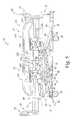
- FIG. 8is a perspective view of an alternative embodiment hospital bed frame having four linkage assemblies supporting an intermediate frame and a deck (in phantom);
- FIG. 9is a side elevation view of the hospital bed of FIG. 8 showing the frame in an upper position supporting the intermediate frame and the deck in an upper position;
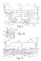
- FIG. 10is a cross-sectional view taken along line 10 - 10 of FIG. 9 showing one of the linkage assemblies including a C-shaped link and a rectangle-shaped link partially positioned in the C-shaped link;
- FIG. 11is a side elevation view of the hospital bed similar to FIG. 9 showing the frame in a lower position supporting the deck in a lower position;
- FIG. 12is a side elevation view of the hospital bed similar to FIG. 9 showing the frame in the Trendelenburg position supporting the deck with a head section of the deck positioned lower than a foot section of the deck;
- FIG. 13is a side elevation view of the hospital bed similar to FIG. 9 showing the frame in the Reverse Trendelenburg position supporting the deck with the head section of the deck positioned higher than the foot section of the deck;
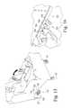
- FIG. 14is a perspective view of a control panel pivotably coupled to the footboard and including a plurality of control buttons for operating various functions of the hospital bed;
- FIG. 15is a perspective view of an alternative embodiment control system including four foot pedals configured to control the various functions of the hospital bed;
- FIG. 16is a perspective view of the control system of FIG. 15 showing a caregiver depressing one of the foot pedals to lower a back section of the hospital bed;
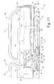
- FIG. 17is a side elevation view of a head end of the hospital bed of FIG. 1 with portions cut away (in partial phantom) showing the deck including the head section (in partial phantom), the back section (in partial phantom) pivotably coupled to the head section, and a tilt mechanism coupled to an intermediate frame of the frame, the back section of the deck, and to the head section of the deck;
- FIG. 18is a top view of the tilt mechanism taking along lines 18 - 18 of FIG. 17 ;
- FIG. 19is a side elevation view similar to FIG. 17 showing the tilt mechanism tilting the head section of the deck relative to the back section of the deck;
- FIG. 20is a side elevation view similar to FIG. 17 showing the tilt mechanism tilting the head section relative to the back section and tilting the back section relative to the intermediate frame;
- FIG. 21is a side elevation view similar to FIG. 17 showing the tilt mechanism tilting the head and back sections of the deck relative to the intermediate frame while maintaining a coplanar relationship between the head and back sections;
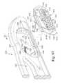
- FIG. 22is a side elevation view of a foot end of the hospital bed showing the deck including a foot section with the footboard coupled thereto and a seat section pivotably coupled to the foot section and the intermediate frame, and a tilt mechanism positioned between the foot and seat sections of the deck and the intermediate frame;
- FIG. 23is a side elevation view similar to FIG. 22 showing the tilt mechanism including an actuator lifting the seat section of the deck to an upper position and a pair of links in a locked position elevating the foot section of the deck in response to the movement of the seat section;
- FIG. 24is a side elevation similar to FIG. 22 showing the actuator in a retracted position and the links of the tilt mechanism in an unlocked position;
- FIG. 25is a side elevation view similar to FIG. 22 showing the actuator lifting the seat section of the deck, the links in the unlocked position, and the foot section of the deck tilting relative to the seat section as the actuator lifts the seat section;
- FIG. 26is a perspective view of the underside of the foot and seat sections of the deck showing the links in the locked position and the tilt mechanism further including a connector link interconnecting the right and left links for simultaneous movement therebetween;
- FIG. 27is a perspective view of one of the siderails including a linkage assembly coupled to the intermediate frame and a clear rail member, with portions broken away, coupled to the linkage assembly;
- FIG. 28is a cross-sectional view taken along line 28 - 28 of FIG. 27 showing the linkage assembly including a retainer including a Z-shaped latch coupled to a catch rod, a lower release handle coupled to the Z-shaped latch, and a patient-accessible upper release handle interacting with the Z-shaped latch through a pair of vertical transfer rods;
- FIG. 29is a side view of a lockout mechanism configured to block movement of the patient-accessible upper release handle
- FIG. 30is a cross-sectional view similar to FIG. 28 showing the patient-accessible upper release handle pivoted inwardly to push the vertical transfer rods downwardly so that the Z-shaped latch is rotated away from the catch rod to permit the siderail to be lowered;
- FIG. 31is a cross-sectional view similar to FIG. 28 showing the siderail in an intermediate lower position
- FIG. 32is a perspective view of the siderail showing the clear rail member coupled to the linkage assembly and a clear armrest pivotably coupled to the clear rail member in a storage position;
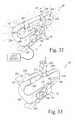
- FIG. 33is a view similar to FIG. 32 showing the armrest in a use position and having a cup or container holder supporting a cup therein;
- FIG. 34is a cross-sectional view taken along line 34 - 34 of FIG. 32 showing the armrest in the storage position, the siderail further including a stop plate coupled to the armrest, a top rail portion of the rail member having a substantially circular lobe and a downwardly extending lobe coupled to the substantially circular lobe;
- FIG. 35is a cross-sectional view similar to FIG. 34 showing the armrest in the use position and the stop plate engaging the downwardly extending lobe so that further clockwise rotation of the armrest is prevented;
- FIG. 36is a perspective view of an alternative embodiment siderail showing the siderail in an upper position
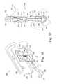
- FIG. 37is a cross-sectional view taken along lines 37 - 37 of FIG. 36 showing the siderail of FIG. 36 including a vertical rail member pivotably coupled about a tubular support member, a pair of handles pivotably coupled to the vertical rail member, a retainer including a vertical pin engaging an aperture formed in the tubular support member, and a pair of cables coupling the vertical pin to the handles, one of said handles (in phantom) in an actuated position pulling the vertical pin from locking engagement with the tubular support member to permit pivoting of the rail member in a counterclockwise (in phantom) or clockwise (in phantom) direction relative to the tubular support member;
- FIG. 38is a perspective view similar to FIG. 36 showing the siderail in a lower position
- FIG. 39is a cross-sectional view similar to FIG. 37 showing the siderail in the lower position with the pin disengaged from the apertures formed in the tubular support member;
- FIG. 40is a perspective view of the hospital bed of FIG. 1 showing the deck and a mattress, with portions broken away, positioned on the deck;
- FIG. 41is a perspective view of the mattress of FIG. 40 (with an outer layer of ticking removed);
- FIG. 42is a cross-sectional view of the mattress of FIG. 40 taken along line 42 - 42 of FIG. 40 showing the mattress including a firming pad positioned near the top of the mattress, an upper foam layer positioned under the firming pad, a crowning bladder positioned under the upper foam layer, a massage motor positioned under the crowning bladder, and a pair of additional foam layers also positioned below the crowning bladder;
- FIG. 43is a cross-sectional view taken along line 43 - 43 of FIG. 40 showing the mattress including another crowning bladder in a deflated position and the deck including a flexible deck panel in an un-flexed position and a flexed position (in phantom);
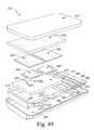
- FIG. 44is a cross-sectional view taken along line 44 - 44 of FIG. 43 , with portions broken away, showing one portion of the flexible panel including an elongated slot and a fastener positioned in the elongated slot to permit the flexible panel to slide relative to the fastener to permit the flexible panel to bow downwardly when weight is applied to the flexible panel (in phantom);
- FIG. 45is a cross-sectional view similar to FIG. 43 showing the crowning bladder in an inflated position to create a crown in the mattress;
- FIG. 46is an end view of the foot section of the mattress of FIG. 41 showing the foot section of the mattress formed to include angled sides to conform to the deck;
- FIG. 47is a side elevation view of the foot section of the mattress of FIG. 41 showing the foot section formed to include slots permitting the foot section to extend and retract;
- FIG. 48is an exploded view of an alternative embodiment mattress
- FIG. 49is an exploded view of another alternative embodiment mattress.
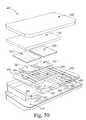
- FIG. 50is an exploded view of yet another alternative embodiment mattress including an air bladder having a plurality of cylinders;
- FIG. 51is a perspective view of an air system for controlling the pressure level in the air bladder of FIG. 50 ;
- FIG. 52is a perspective view of an alternative embodiment footboard releasably coupled to the deck to permit the footboard to be removed from the deck and positioned over the siderails to provide a table (in phantom) for a patient;
- FIG. 53is a cross-sectional view showing the footboard of FIG. 52 in the table position and positioned over the pair of siderails;
- FIG. 54is a perspective view of alternative headboard showing the headboard including a tubular frame removably coupled to the deck and a fabric screen coupled to the tubular frame;
- FIG. 55is a cross-sectional view taken along lines 55 - 55 of FIG. 54 showing the fabric screen coupled to the tubular frame;
- FIG. 56is a cross-sectional view of yet another alternative embodiment footboard removed from the deck and having a base and pair of side flaps pivotably coupled to the base and positioned on the siderails to support the base;
- FIG. 57is a view similar to FIG. 56 showing the side flaps in a storage position on the outside of the base;
- FIG. 58is a view similar to FIG. 57 showing another alternative footboard having a base and a pair of side flaps positioned in a storage position on the inside of the base;
- FIG. 59is a perspective view of yet another alternative embodiment removable footboard positioned over a pair of siderails to provide a table;
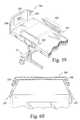
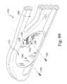
- FIG. 60is a cross-sectional view of the footboard of FIG. 59 showing the footboard positioned over the inwardly slanting siderails;
- FIG. 61is a perspective view of another alternative embodiment hospital bed showing the hospital bed including a frame, a deck coupled to and positioned above the frame with a head section of the deck tilted relative to an intermediate frame of the frame, a mattress supported by the deck, a headboard coupled to the frame, a footboard coupled to the deck, a pair of head end siderails coupled to the head section of the deck, a pair of foot end siderails coupled to the intermediate frame, and a pair of gap fillers coupled to the footboard and extending to the foot end siderails;
- FIG. 62is a perspective view of the headboard of FIG. 61 showing the headboard coupled to a portion of the intermediate frame, the bed including a pocket and a panel spaced apart from the headboard and aligned to fit within the pocket of the headboard;
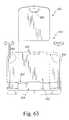
- FIG. 63is an end view of the headboard of FIG. 61 showing the panel spaced apart from the headboard;
- FIG. 64is a view similar to FIG. 63 showing the panel positioned in the pocket of the headboard;
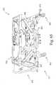
- FIG. 65is a perspective view of the bed of FIG. 61 with the deck, mattress, siderails, and headboard removed showing the frame including the intermediate frame, a shroud covering a base frame, and four linkage assemblies supporting the intermediate frame over the shroud;
- FIG. 66is a perspective view of a portion of the base frame showing a caster brake pedal coupled to the base frame and spaced apart from a caster coupled to the base frame;
- FIG. 67is a cross-sectional view taken along line 67 - 67 of FIG. 66 showing a link extending from an arm of the caster brake pedal to an arm of a caster braking mechanism including a hexagonal rod;
- FIG. 68is a perspective view showing a hinge coupling one of the gap fillers of FIG. 61 to the footboard;
- FIG. 69is a side elevation view of the footboard and one of the gap fillers of FIG. 61 showing the footboard including a first fastener and the gap filler including a second fastener aligned with the first fastener to couple the gap filler to the footboard;
- FIG. 70is a top plan view of the footboard, one of the foot end siderails, and one of the gap filler of FIG. 61 showing the gap filler positioned between the foot end siderail and the mattress;
- FIG. 71is a side elevation view of the bed of FIG. 61 showing the deck in a bed position with the head section of the deck co-planar with a seat section of the deck;
- FIG. 72is a view similar to FIG. 71 showing the head section of the deck tilted relative to the seat section of the deck;
- FIG. 73is a view similar to FIG. 71 showing the head section of the deck tilted relative to the seat section of the bed and foot end of the head end siderail positioned adjacent to a notch formed in the foot end siderail;
- FIG. 74is a partial perspective view of one of the foot end siderails of FIG. 61 showing the foot end siderail including a rail member having a pocket, the bed further including a controller positioned for insertion into the pocket;
- FIG. 75is a cross-sectional view taken along line 75 - 75 of FIG. 74 showing the rail member including a pair of recesses and the controller including a pair of ball-detents aligned to fit within the recesses of the rail member to removably secure the controller in the pocket of the foot end siderail;
- FIG. 76is a side elevation view of one of the head end siderails showing the head end siderail including a longitudinal slot and the bed further including a controller positioned in the slot to slide along the length thereof;
- FIG. 77is a cross-sectional view taken along line 77 - 77 of FIG. 76 showing the controller including a pair of tabs configured to removably and slidably couple the controller to the head end siderail;
- FIG. 78is a side elevation view of one of the foot end siderails showing the foot end siderail including a longitudinal slot and the controller of FIG. 76 positioned in the slot to slide along the length thereof;
- FIG. 79is a side elevation view of a foot end of the hospital bed showing the deck including seat section pivotably coupled to the intermediate frame and a foot section pivotably coupled to the seat section, the bed further including an actuator coupled to the intermediate frame and the seat section, the foot section resting on a roller coupled to the intermediate frame, and a link coupled to the foot section and the intermediate frame;
- FIG. 80is a view similar to FIG. 79 showing the actuator in an extended position tilting the seat section of the deck so that the foot section of the deck rolls on the roller and also assumes a tilted position;
- FIG. 81is a view similar to FIG. 79 showing the actuator in the extended position and the seat section in the tilted position, the link being coupled to the intermediate frame to support the foot section is a raised position;
- FIG. 82is a perspective view of the deck and intermediate frame, with portions broken away, showing a spill guard positioned between the head section of the deck and the seat section of the deck;
- FIG. 83is a cross-sectional view taken along line 83 - 83 of FIG. 82 showing the spill guard positioned between the head and seat sections of the deck;
- FIG. 84is a perspective view of a portion of the intermediate frame showing the bed further including a male communications connector coupled to the intermediate frame and a female communications connector aligned to be coupled to the male communications connector;
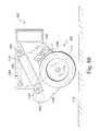
- FIG. 85is a perspective view of a propulsion device coupled to the base frame
- FIG. 86is a cross-sectional view taken along line 86 - 86 of FIG. 85 showing the propulsion device including a wheel and an actuator in a retracted position supporting the wheel in a position spaced apart from the floor;
- FIG. 87is a view similar to FIG. 86 showing the actuator in an extended position so that the wheel contacts the floor;
- FIG. 88is a perspective view of the mattress of FIG. 61 , with a protective cover removed, showing the mattress including a foot section including a retractable foam portion and a heel-pressure relief bladder positioned in a cavity formed in the retractable foot section;
- FIG. 89is a side elevation view of the deck and mattress showing a tall person positioned on the mattress and the foot section of the deck in an extended position with the heel of the tall person positioned over the heel-pressure relief bladder;
- FIG. 90is a view similar to FIG. 89 showing a short person positioned on the mattress and the foot section in a retracted position with the heel of the short person positioned over the heel-pressure relief bladder;
- FIG. 91is a cross-sectional view taken along line 91 - 91 of FIG. 90 showing the heel-pressure relief bladder positioned in the cavity formed in the retractable foam portion;
- FIG. 92is a perspective view of another alternative embodiment hospital bed showing the hospital bed including a frame having a base frame supported by a plurality of casters, a weigh frame, and a pair of support arms positioned between the weigh frame and the base frame, a headboard coupled to the base frame, a footboard coupled to the deck, and four foot pedal controls coupled to the base frame;
- FIG. 93is a top plan view of the frame showing the rectangular weigh frame and the frame further including an intermediate frame coupled to and positioned within the perimeter of the weigh frame;
- FIG. 94is a perspective view of the weigh frame and intermediate frame
- FIG. 95is side elevation view the hospital bed of FIG. 92 taken along line 95 - 95 of FIG. 93 showing the weigh frame and intermediate frame supported by the lift arms in a raised position;
- FIG. 96is a view similar to FIG. 95 showing the lift arms supporting the weigh frame in a lowered position
- FIG. 97is a partial perspective view of a first of the pair of foot end siderails showing the first foot end siderail including a rail member and a removable controller mount aligned for coupling to the rail member with a pair of screws, the removable controller mount having a pocket, and the bed further including a controller positioned in the pocket of the removable controller mount;
- FIG. 98is a cross-sectional view taken along line 98 - 98 of FIG. 97 ;
- FIG. 99is a partial perspective view of a second of the pair of foot end siderails showing the second foot end siderail including a rail member and a substantially flat removable panel, with portions broken away, coupled to the rail member;
- FIG. 100is a cross-sectional view taken along line 100 - 100 of FIG. 99 ;
- FIG. 101is a side elevation view of the controller of FIG. 97 ;
- FIG. 102is a cross-sectional view taken along line 102 - 102 of FIG. 104 showing another controller including a latch configured to removably and slidably couple the controller to one of the head and foot end siderails;
- FIG. 103is a partial perspective view of the latch configuration of FIG. 102 ;
- FIG. 104is a side elevation view showing a back side of the controller of FIG. 102 showing the controller including a housing having a pair of spaced-apart surfaces defining curved channels to complement the contour of the siderails (shown in phantom);
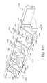
- FIG. 105is a perspective view showing a pedal housing coupled to a portion of the base frame and four pedals pivotably coupled to the pedal housing;
- FIG. 106is a cross-sectional view taken line 106 - 106 of FIG. 105 showing one of the foot pedals including a pedal pivotably coupled to the pedal housing, a first spring positioned between the base frame and the pedal to bias the pedal in a counterclockwise direction, a second spring positioned between the base frame and the pedal to bias the pedal in a clockwise direction, a magnet coupled to a distal end of the pedal, and a sensor arranged to detect the position of the magnet;
- FIG. 107is a partial perspective view showing the head section of the deck titled relative to the weigh frame
- FIG. 108is a cross-sectional view of the head end siderail taken along line 108 - 108 of FIG. 109 ;
- FIG. 109is side elevation view of the bed of FIG. 92 showing the head section of the deck titled relative to the weigh frame and the head end siderail in an up position;
- FIG. 110is a view similar to FIG. 109 showing the head end siderail in a lowered position
- FIG. 111is side elevation view of a portion of the head end siderail in the raised position showing the siderail including a pair of spaced-apart links pivotably coupled to a longitudinally extended rod, the rod including two pairs of cylindrical cams, and each link including a pair of spaced-apart cylindrical cams positioned to contact the cylindrical cams of the rod;
- FIG. 112is a view similar to FIG. 111 showing the siderail translated to the right when in the lowered position;
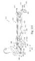
- FIG. 113is a perspective view of a base frame of another alternative embodiment bed showing four casters coupled to the base frame, a first pair of foot pedals coupled to two of the casters, a second pair of foot pedals longitudinally spaced apart from the other two casters, a transverse link coupling the second pair of foot pedals together, and a pair of spaced-apart longitudinally extending links coupling the first and second pair of foot pedals together so that all four casters are linked to move simultaneously;
- FIG. 114is a view identical to FIG. 90 showing a deck in a substantially flat bed position.
- FIG. 115is a view similar to FIG. 90 showing a head section of the deck raised to a titled position and the foot section of the deck extended in response to the head section of the deck being raised.
- a hospital bed 10including a frame 12 positioned on the floor, a deck 14 coupled to frame 12 , a mattress 13 positioned on deck 14 , a headboard 16 coupled to frame 12 , a footboard 18 coupled to deck 14 , and a pair of split siderails 20 , 21 coupled to frame 12 .
- Frame 12is configured to raise and lower deck 14 relative to the floor and to move deck 14 to the Trendelenburg position and the Reverse Trendelenburg position.
- headboard or first barrier 16includes a curved base 30 coupled to frame 12 and a center panel 34 removably coupled to base 30 .
- Base 30includes a pair of handles 48 to facilitate pushing hospital bed 10 about a care facility.
- center panel 34When necessary a caregiver removes center panel 34 from base 30 and positions center panel 34 under a patient's torso to assist the caregiver in administering CPR to the patient.
- the removability of center panel 34also permits access to the patient during such a procedure from a head end of hospital bed 10 to allow the caregiver to more easily administer the CPR procedure.
- Center panel 34includes a body portion 36 , a handle portion 38 coupled to body portion 36 to define an opening 42 therebetween, and a pair of tongues 44 configured to mate with base 30 and provide sliding movement therebetween.
- the preferred embodiment of center panel 34is made of a clear plastics material such as acrylic or clarified polyethylene (PETG) so that a caregiver may view a patient positioned on hospital bed 10 through headboard 16 .
- the center panelis made of other materials known to those of ordinary skill in the art that have transparent, translucent, or non-opaque properties so that visible light passes therethrough.
- portions or all of the center panelis made of an opaque material.
- base 30is formed to include a pair of grooves 46 configured to receive tongues 44 of center panel 34 so that center panel 34 is slidably coupled to base 30 .
- frame 12includes a rectangular lower frame member or base frame 32 , a plurality of casters 50 coupled to base frame 32 to permit hospital bed 10 to be rolled about a care facility, a rectangular upper frame member or intermediate frame 52 , a linkage system 54 coupled to intermediate and base frames 52 , 32 to permit relative motion therebetween, and an actuator system 56 providing power to actuate linkage system 54 and move upper member 52 relative to base frame 32 .
- Linkage system 54includes a pair of head links 58 pivotably coupled to a head end 53 of intermediate frame 52 and slidably coupled to base frame 32 , a pair of foot links 60 pivotably coupled to a foot end 55 of intermediate frame 52 and slidably coupled to base frame 32 , and a pair of guide links 62 pivotably coupled to respective foot links 60 and pivotably coupled to base frame 32 at a fixed pivot point.
- linkage system 54further includes rollers 59 that ride in hollow base frame 32 and pins 61 extending through elongated slots 70 formed in inner side walls of base frame 32 to rotatably couple rollers 59 to the lower ends of head and foot links 58 , 60 .
- Rollers 59ride over a lower wall 63 of base frame 32 to provide smooth rolling movement between head and foot links 58 , 60 and base frame 32 to facilitate the sliding movement of head and foot links 58 , 60 in base frame 32 .
- Hospital bed 10further includes a caster braking system including a caster-brake link 65 extending through hollow base frame 32 adjacent to roller 59 as shown in FIG. 4 .
- the caster braking systeminterconnects each caster 50 to provide simultaneous braking of casters 50 .
- the caregiversteps on one of foot brake pedals 63 and the caster braking system locks casters 50 against rolling.
- a caster braking system similar to the caster braking system of the present disclosureis more fully disclosed in U.S. patent application Ser. No. 09/263,039, filed Mar. 5, 1999, to Mobley et al., entitled Caster and Braking System, which is expressly incorporated by reference herein.
- Guide links 62restrict the motion of foot links 60 such that the pivot point between foot links 60 and intermediate frame 52 is restrained to move vertically without moving horizontally. This restriction prevents horizontal movement of intermediate frame 52 relative to base frame 32 during raising and lowering of intermediate frame 52 . This restrained movement prevents intermediate frame 52 from moving through an arch while moving between the upper and lower positions so that intermediate frame 52 can be raised and lowered without requiring additional hospital room for clearance.
- the distance between pivot points 49 , 51 of guide links 62is one half the distance between axis 47 of rollers 59 and pivot points 45 of the upper ends of foot links 60 and that each guide link 62 is pivotably coupled to the respective foot link 60 at pivot point 51 that is one half the distance between axis 47 of the associated roller 59 and pivot point 45 of the upper end of the respective foot link 60 .
- the distance between upper pivot point 51 of each guide link 62 and the lower pivot point 49 of each guide link 62is equal to the distance between upper pivot point 51 of each guide link 62 and upper pivot point 45 of each foot link 60 .
- upper pivot points 45 of foot links 60are maintained in vertical alignment with lower pivot point 49 of guide links 62 during raising and lower of frame members 52 relative to frame member 32 .
- Actuator system 56provides the force and power necessary to raise and lower intermediate frame 52 .
- Actuator system 56includes a head link actuator 64 coupled to head links 58 and intermediate frame 52 and a foot link actuator 66 coupled to foot links 60 and intermediate frame 52 .
- Actuator 64is coupled to head links 58 through an extension link 75 that is rigidly coupled to a cross strut (not shown) which extends between and is rigidly coupled to each of head links 58 .
- actuator 66is coupled to foot links 60 through an extension link 77 that is rigidly coupled to a cross strut (not shown) which extends between and which is rigidly coupled to each of foot links 60 .
- the cross strut coupled to head links 58coordinates the simultaneous movement thereof, whereas the cross strut coupled to foot links 60 coordinates simultaneous movement thereof.
- Actuators 64 , 66have expandable lengths to adjust the angular position of head and foot links 58 , 60 relative to intermediate frame 52 so that head and foot ends 53 , 55 of intermediate frame 52 can be raised or lowered.
- Each of actuators 64 , 66is preferably an electric linear actuator having respective cylinder bodies 67 , cylinder rods 69 , and motors 71 that operate to extend and retract cylinder rods 69 relative to cylinder bodies 67 .
- Cylinder rods 69are each pivotably coupled to respective pivot links 75 , 77 and motors 71 are each pivotably coupled to a bracket 79 included in intermediate frame 52 as shown, for example, in FIG. 3 .
- intermediate frame 52When head and foot link actuators 64 , 66 are actuated simultaneously, such that one of actuators 64 , 66 extends while the other actuator 66 , 64 retracts, intermediate frame 52 either raises away from or lowers toward base frame 32 so that intermediate frame 52 is maintained in a horizontal position and does not “swing” outwardly or inwardly relative to base frame 32 .
- head link actuator 64is activated and foot link actuator 66 is maintained at a constant length
- intermediate frame 52moves to the Trendelenburg position as shown in FIG. 5 so that head end 53 of intermediate frame 52 is lowered and foot end 55 of intermediate frame 52 is slightly raised.
- intermediate frame 52moves to the Reverse Trendelenburg position so that foot end 55 of intermediate frame 52 lowers and head end 53 of intermediate frame 52 slightly raises as shown in FIG. 6 .
- deck 14is lowered by activating both head and foot link actuators 64 , 66 .
- foot link actuator 66increases, the angle between foot links 60 and intermediate frame 52 decreases and foot end 55 of intermediate frame 52 lowers.
- head link actuator 64decreases, the angle between head links 58 and intermediate frame 52 increases and head end 53 of intermediate frame 52 lowers as shown, for example, in FIG. 5 .
- intermediate frame 52continues to lower from the upper position to a lower position as shown in FIG. 5 (in phantom).
- intermediate frame 52remains substantially horizontal while moving from the upper position, shown in FIG. 3 , to the lower position shown in phantom in FIG. 5 (in phantom).
- link actuator 64is lengthened and foot link actuator 66 is simultaneously shortened until each actuator 64 , 66 returns to its original length as shown in FIG. 3 .
- Linkage system 54 and actuator system 56also cooperate to move intermediate frame 52 to the Trendelenburg position as shown in FIG. 6 .
- head link actuator 64decreases its length such that the angle between intermediate frame 52 and head links 58 increases. Head end 53 of intermediate frame 52 lowers and the length of foot link actuator 66 remains substantially constant to provide a pivot point about which intermediate frame 52 rotates. As intermediate frame 52 rotates, foot end 55 of intermediate frame 52 is slightly raised as shown in FIG. 6 . To reposition intermediate frame 52 in the upper horizontal position, the length of head link actuator 64 is increased until it is returned to its previous length.
- Actuator system 56 and linkage system 54also cooperate to position intermediate frame 52 in the Reverse Trendelenburg position as shown in FIG. 7 .
- the length of foot link actuator 66is increased so that the angle between foot links 60 and intermediate frame 52 is decreased and foot end 55 of intermediate frame 52 lowers.
- the overall length of head link actuator 64remains substantially constant so that intermediate frame 52 pivots about head links 58 .
- head end 53 of intermediate frame 52is slightly raised as foot end 55 of intermediate frame 52 lowers.
- the length of foot link actuator 66is decreased until it is returned to its previous length.
- Hospital bed 10further includes two dampers 72 coupled to the inner walls of base frame 32 to engage the lower ends of foot links 60 .
- Dampers 72aid in raising intermediate frame 52 and deck 14 from the lower and Reverse Trendelenburg positions.
- dampers 72resist movement of the foot links 60 and store potential energy as a result of the lowering of foot end 55 of intermediate frame 52 .
- damper 72is compressed so that potential energy is stored.
- intermediate frame 52is moved from the lower position, as shown in FIG. 5 , to the upper position as shown in FIG.
- dampers 72aid foot link actuators 66 in raising foot end 55 of intermediate frame 52 by pushing lower ends of foot links 60 in the direction that raises foot end 55 of intermediate frame 52 to the upper position. Because dampers 72 store potential energy during lowering of foot end 55 of intermediate frame 52 , foot link actuator 66 does not need to be as powerful to raise foot end 55 of intermediate frame 52 from the lower position to the upper position. According to an alternative embodiment frame, a more powerful foot link actuator is provided and dampers are not provided.
- frame 612includes a lower frame member or base frame 632 , plurality of casters 50 coupled to base frame 632 to permit the hospital bed to be rolled about a care facility, an upper frame member or intermediate frame 652 , a linkage system 654 coupled to intermediate and base frames 652 , 632 to permit relative motion therebetween, and an actuator system 656 providing power and force to actuate linkage system 654 and move intermediate frame 652 relative to base frame 632 .
- Linkage system 654includes a pair of head link assemblies 658 pivotably coupled to intermediate frame 652 near a head end 653 of intermediate frame 652 and rigidly coupled to base frame 632 and a pair of foot link assemblies 660 slidably coupled to intermediate frame 652 near a foot end 655 of intermediate frame 652 and rigidly coupled to base frame 632 .
- foot link assembly 660further includes rollers 659 that ride in hollow intermediate frame 652 .
- Rollers 659are coupled to the upper ends of foot link assemblies 660 to facilitate the sliding of foot link assemblies 660 relative to intermediate frame 652 .
- Rollers 659ride under an upper wall 663 of intermediate frame 652 to provide smooth rolling movement between foot link assemblies 660 and intermediate frame 652 .
- Actuator system 656provides the power and force necessary to raise and lower upper frame assembly 652 .
- Actuator system 656includes a head link actuator 664 coupled to head link assemblies 658 and base frame 632 and a foot link actuator 666 coupled to foot link assemblies 660 and base frame 632 .
- Actuators 664 , 666are similar to actuators 64 , 66 and have expandable lengths to adjust the angular position of head and foot link assemblies 658 , 660 relative to base frame 632 so that head and foot ends 653 , 655 of intermediate frame 652 can be raised or lowered.
- intermediate frame 652When head and foot link actuators 664 , 666 are actuated simultaneously such that both actuators 664 , 666 retract or extend, intermediate frame 652 either raises away from or lowers toward base frame 632 so that intermediate frame 652 is maintained in a horizontal position.
- head link actuator 664is activated and foot link actuator 666 is maintained at a constant length, intermediate frame 652 moves to the Trendelenburg position, as shown in FIG. 12 , so that head end 653 of intermediate frame 652 is lowered and foot end 655 of intermediate frame 652 is raised.
- intermediate frame 652moves to the Reverse Trendelenburg position so that foot end 655 of intermediate frame 652 lowers and head end 653 of intermediate frame 652 raises as shown in FIG. 13 .
- intermediate frame 652is lowered by activating both head and foot link actuators 664 , 666 .
- the angle between foot link assemblies 660 and intermediate frame 652decreases and foot end 655 of intermediate frame 652 lowers.
- head link actuator 664decreases, the angle between head link assemblies 658 and intermediate frame 652 decreases and head end 653 of intermediate frame 652 lowers as shown, for example, in FIG. 11 .
- intermediate frame 652continues to lower from the upper position to a lower position as shown in FIG. 11 .
- intermediate frame 652remains substantially horizontal while moving from the upper position shown in FIG. 9 to the lower position shown in FIG. 11 (in phantom). To reposition intermediate frame 652 back in the upper position, head and foot link actuators 664 , 666 are simultaneously lengthened until each actuator 664 , 666 is returned to its original length.
- linkage system 654 and actuator system 656cooperate to move intermediate frame 652 to the Trendelenburg position as shown in FIG. 12 .
- head link actuator 664decreases its length such that the angle between intermediate frame 652 and head link assemblies 658 decreases and head end 653 of intermediate frame 652 lowers and the length of foot link actuator 666 remains substantially constant to provide a pivot point about which intermediate frame 652 rotates such that foot end 655 of intermediate frame 652 is slightly raised.
- the length of head link actuator 664is increased until it is returned to its original length as shown in FIG. 9 .
- Actuator system 656 and linkage system 654also cooperate to position intermediate frame 652 in the Reverse Trendelenburg position as shown in FIG. 13 .
- the length of foot link actuator 666is decreased so that the angle between foot link assemblies 660 and intermediate frame 652 is decreased and foot end 655 of intermediate frame 652 lowers.
- the overall length of head link actuator 664remains substantially constant so that intermediate frame 652 pivots about head link assemblies 658 .
- head end 653is slightly raised as foot end 655 lowers.
- the length of foot link actuator 666is increased until it is returned to its original length as shown in FIG. 9 .
- head and foot link assemblies 658 , 660are configured to maintain a vertical orientation of the upper end thereof during movement of upper frame 652 between the various positions.
- Each head and foot link assembly 658 , 660includes first, second, third, and fourth links 668 , 670 , 672 , 674 that cooperate to maintain third link 672 in said vertical position.
- Each head and foot link assembly 658 , 660further includes a load cell 676 positioned between respective blocks 677 and rollers 659 and respective third links 672 that measure the respective weight applied to each third link 672 . Because third links 672 remain vertical, no trigonometric calculations must be made to correct the weight measurement due to the orientation of load cell 676 relative to the floor.
- first links 668comprise a series of brackets that are rigidly coupled to lower frame 632 .
- Second links 670are C-shaped and are pivotably coupled to the respective first links 668 by pins 669 .
- a strut 678extends between the respective second links 670 of foot link assemblies 660 to provide a rigid connection therebetween to coordinate simultaneous movement of foot link assemblies 660 during actuation by foot link actuator 666 .
- An extension 680is rigidly coupled to strut 678 to provide a moment arm through which the linear force provided by foot link actuator 666 is converted to torque for rotating second links 670 of foot link assemblies 660 .
- a strut 682extends between the respective second links 670 of head link assemblies 658 to provide a rigid connection therebetween to coordinate simultaneous movement of head link assemblies 658 during actuation by head link actuator 664 .
- An extension 684is rigidly coupled to strut 682 to provide a moment arm through which the linear force provided by head link actuator 664 is converted to torque for rotating second links 670 of head link assemblies 658 .
- Third links 672comprise a series of C-shaped brackets pivotably coupled to respective second links 670 by pins 671 .
- a strut 686extends between respective third links 672 of foot link assemblies 660 to provide a rigid connection therebetween to coordinate simultaneous movement of foot link assemblies 660 during actuation by foot link actuator 666 .
- a strut 688extends between the respective third links 672 of head link assemblies 658 to provide a rigid connection therebetween to coordinate simultaneous movement of head link assemblies 658 during actuation by head link actuator 664 .
- Load cells 676are rigidly coupled to respective struts 686 , 688 as shown in FIG. 8 .
- Fourth links 674comprise flat elongated bars pivotably coupled to respective third links 672 by pins 673 and first links 668 by pins 675 to provide a complete four bar linkage for each head and foot link assembly 658 , 660 .
- each respective fourth link 674is positioned partially within the respective C-shaped second link 670 to block insertion of objects between the respective second and fourth links 670 , 674 to prevent pinching.
- each respective second link 670is formed to include a notch 690 positioned to provide clearance for pin 675 while each foot and head link assemblies 658 , 660 is in the lower position.
- third link 672remains substantially vertical during movement of intermediate frame 652 through the various positions.
- second links 670are turned by respective head and foot link actuators 664 , 666 , third link 672 directs the horizontal and vertical movement of pin 673 so that pin 673 remains in substantially the same vertical and horizontal position relative to pin 671 .
- third link 672remains substantially vertical regardless of the vertical positions of head and foot ends 653 , 655 of intermediate frame 652 .
- load cells 676also remain in a substantially vertical orientation simplifying the overall calculation necessary for determining the weight of the patient. To determine the total weight of the patient, the weights measured by load cells 676 are totaled and the predetermined weight of the components of the hospital bed supported by load cells 676 are subtracted from this total resulting in the weight of the patient. The weights measured from load cells 676 do not need adjusted for the angular position of upper frame 652 because load cells 676 remain vertically oriented.
- Pair of coupling blocks 677are fixed to intermediate frame 652 adjacent to head end 653 thereof and load cells 676 associated with head link assemblies 658 each include a cylindrical stud 679 extending transversely therefrom into a bore formed in the respective block 677 .
- blocks 677tilt along with frame member 652 while pivoting relative to the associated load cells 676 on cylindrical stud 679 about pivot axis 681 .
- rollers 659rotate about pivot axis 683 relative to the associated load cells 676 while also rolling either toward or away from blocks 677 depending upon the direction that intermediate frame 652 tilts.
- footboard or second barrier 18includes a modular control unit 692 for controlling the automated features of hospital bed 10 .
- Footboard 18further includes a base 694 and modular control unit 692 includes a support panel 696 slidably coupled to base 694 and a control panel 698 pivotably coupled to support panel 696 .
- Control panel 698is rotatable between a use position, as shown in FIG. 14 , and a storage position in a recess 699 formed in support panel 696 .
- Support panel 696is also formed to include a notch 697 in which a caregiver can grab a distal end of control panel 698 to rotate it back to the use position.
- control unit 692is removable from base 694 to permit replacement of control unit 692 for repairs or upgrading.
- multiple configurations of modular control unitsare provided at the manufacturing facility. Depending on the specific configuration of the hospital bed, a different control unit will be provided with the respective hospital bed by sliding the respective control unit into standard base 694 .
- Control panel 698includes a series of buttons 710 for controlling the various functions of hospital bed 10 .
- Deck 14includes head, back, seat, and foot portions or sections 22 , 24 , 26 , 28 that can be tilted relative to intermediate frame 52 and several mechanisms configured to adjust the angular position of these deck sections 22 , 24 , 26 , 28 .
- foot section 28 of deck 14is extendable, seat section 26 of deck 14 can be tilted relative to intermediate frame 52 , back section 24 of deck 14 can be tilted relative to intermediate frame 52 , and head section 22 of deck 14 can also be tilted relative to intermediate frame 52 .
- Series of buttons 710includes a first pair of buttons 711 for raising and lowering intermediate frame 52 and a second pair of buttons 712 for raising and lowering seat section 26 .
- Series of buttons 710also includes a third pair of buttons 714 for raising and lowering back section 24 relative to intermediate frame 52 and a fourth pair of buttons 716 for simultaneously raising and lowering seat and back sections 26 , 24 .
- Another set of buttons 718is provided for controlling the various functions of the mattress as will be described in greater detail below.
- Control panel 698further includes a display 719 for monitoring the status of the various functions of hospital bed 10 .
- the series of buttonsalso includes a pair of buttons for moving the intermediate frame between the Trendelenburg and Reverse Trendelenburg positions, extending and retracting the foot section of the deck, and any other function of the bed.
- Control panel 698preferably also includes buttons and a display associated with a bed exit and weighing system of bed 10 .
- Control system 750includes a plurality of pedals 752 pivotably coupled to the base frame. Each pedal 752 interacts with a three-position, dual contact switch that is activated by upward or downward movement of said pedal 752 from a middle, neutral position to operate a specific function of the hospital bed. For example, a first pedal 754 is pivoted upwardly to raise the intermediate frame and stepped on to lower the intermediate frame. A second pedal 756 is provided for tilting and untilting back section 24 relative to intermediate frame 52 .
- Series of pedals 752also includes a third pedal 758 for moving intermediate frame 52 between the Trendelenburg and Reverse Trendelenburg positions and a fourth pedal for 760 for tilting and untilting seat section 26 relative to intermediate frame 52 .
- the plurality of pedalsalso includes a pedal for extending and retracting foot section 28 of the hospital bed.
- Each of pedals 752therefore, is operated in an intuitive manner to control the various functions of the hospital bed. That is, pedals 752 are stepped on to perform a “down” function and are lifted upwardly with the top of a user's foot to perform an “up” function.
- deck 14includes several sections 22 , 24 , 26 , 28 that can be tilted relative to intermediate frame 52 .
- Head section 22is positioned adjacent to headboard 16 and is pivotably coupled to back section 24 by a hinge 78 as shown in FIG. 17 .
- Back section 24is pivotably coupled to upwardly extending flanges 73 of intermediate frame 52 by a hinge 76 .
- Seat section 26is pivotably coupled to upwardly extending flanges 73 of intermediate frame 52 by a hinge 116 as shown in FIGS. 22-25 .
- Foot section 28is pivotably coupled to seat section 26 by a hinge 118 .
- Footboard 18is coupled to foot section 28 .
- Seat and foot sections 26 , 28have tapered ends 25 , 27 providing clearance therebetween during titling of foot section 28 relative to seat section 26 as shown in FIG. 25 .
- all sections 22 , 24 , 26 , 28are pivotable relative to intermediate frame 52 .
- Hospital bed 10includes a tilt mechanism 74 that enables head and back sections 22 , 24 to be moved automatically relative to intermediate frame 52 (see FIGS. 20 and 21 ) and head section 22 to be movable automatically relative to back section 24 (see FIGS. 19 and 20 ).
- tilt mechanism 74includes a tilt actuator 80 coupled to intermediate frame 52 , a pair of transfer linkages 82 pivotably coupled to tilt actuator 80 , a transfer shaft 84 coupled to transfer linkages 82 , a head-tilt linkage 86 pivotably coupled to head section 22 and transfer shaft 84 , and a back-tilt linkage assembly 88 pivotably and slidably coupled to transfer shaft 84 and rigidly coupled to back section 24 .
- back-tilt linkage assembly 88includes a pair of links 90 rigidly coupled to back section 24 of deck 14 . Links 90 include slots 92 sized to receive transfer shaft 84 .
- tilt actuator 80is activated to push transfer linkage 82 to the right, as shown in FIG. 18 , which pulls head tilt linkage 86 to the right to slide transfer shaft 84 in slots 92 as shown in FIG. 19 .
- This relative movement of transfer shaft 84 relative to link 90pivots head section 22 relative to back section 24 .
- head-tilt linkage 86pushes the lower right hand corner of head section 22 outwardly and hinge 78 continues to pivotably couple head section 22 to back section 24 , head section 22 tilts relative to back section 24 as shown in FIG. 19 .
- tilt actuator 80continues to push transfer linkage 82 to the right, transfer shaft 84 reaches the right-hand ends of slots 92 and engages links 90 . Transfer shaft 84 then pushes links 90 to the right to pivot back section 24 relative to intermediate frame 52 as shown in FIG. 20 . Because first hinge 76 pivotably couples back section 24 to intermediate frame 52 and links 90 are coupled to a lower left hand corner of back section 24 that is actuated to the right by tilt actuator 80 , back section 24 tilts relative to intermediate frame 52 . Furthermore, the additional actuation of tilt actuator 80 continues the movement of head section 22 relative to intermediate frame 52 so that the degree of tilt between head section 22 and back section 24 is maintained as back section 24 is tilted relative to intermediate frame 52 as shown in FIG. 20 . To return head and back sections 22 , 24 to the horizontal position, the length of tilt actuator is shortened until it reaches its original length.
- Back-tilt linkage assembly 88is configured to enable restriction of the relative movement of head and back section 22 during actuation of tilt actuator 80 .
- Back-tilt linkage assembly 88further includes a pair of blockers 94 pivotably coupled to link 90 to move between an unblocking position (see FIG. 17 ) permitting movement of head section 22 relative to back section 24 and a blocking position (see FIG. 21 ) restraining movement of head section 22 relative to back section 24 . While in the unblocking position, transfer shaft 84 is free to move in slots 92 permitting movement of link 90 relative to head tilt linkage 86 so that head section 22 can tilt relative to back section 24 .
- transfer shaft 84is prevented from moving in slots 92 so that the initial movement of tilt actuator 80 not only moves head-tilt linkage 86 and head section 22 but also moves links 90 of back-tilt linkage assembly 88 and back section 24 .
- Thiscauses head section 22 to tilt relative to intermediate frame 52 and back section 24 to simultaneously tilt relative to intermediate frame 52 so that head and back sections 22 , 24 remain substantially coplanar to one another as shown in FIG. 21 .
- Back-tilt linkage assembly 88further includes a pair of adjustment screws 89 , 91 extending into links 90 for adjusting the effective length of slots 92 . As shown in FIG. 17 , screw 89 extends into the right end of link 90 . If screw 89 is turned further into link 90 , the effective length of the right end of slot 92 decreases to shorten the travel range of transfer shaft 84 in the right end of slot 92 . By decreasing the effective length of the right end of slots 92 , the degree of maximum tilt between head and back sections 22 , 24 is reduced.
- screw 91extends into the left end of link 90 .
- the effective length of the left end of slot 92decreases to shorten the travel range of transfer shaft 84 in the left end of slot 92 .
- the degree of minimum tilt between head and back sections 22 , 24is increased.
- back-tilt linkage assembly 88includes a blocker lever 96 pivotably coupled to back section 24 , cams 98 rigidly coupled to blocker lever 96 , cam followers 100 rigidly coupled to blockers 94 , and stops 110 rigidly coupled to links 90 .
- Blocker lever 96 and cams 98are movable between a disengaged position, as shown in FIG. 17 , and an engaged position as shown in FIG. 21 .
- cams 98are spaced apart from cam followers 100 and blockers 94 are in the unblocking position so that transfer shaft 84 is capable of moving in slots 92 .
- blockers 94pivot about pins 112 so that blockers 94 cover slots 92 and transfer shaft 84 is blocked from moving in slots 92 .
- handle 114To move blocker lever 96 to the engaged position, handle 114 is gripped and turned counter-clockwise in the direction of phantom arrow 115 , shown in FIG. 17 , so that cams 98 engage cam followers 100 .
- Cam followers 100have a slight angle relative to the length of blockers 94 so that cams 98 ride up cam followers 100 to rotate blockers 94 relative to links 90 .
- Blockers 94continue to rotate about pins 112 until blockers 94 engage stops 110 preventing blockers 94 from rotating past the desired position.
- tilt mechanism 74has a first configuration, corresponding to blockers 94 being in the unblocking position, in which head section 22 automatically tilts relative to back section 24 during raising of head and back sections 22 , 24 from a lowered, horizontal position by actuator 80 and tilt mechanism 74 has a second configuration, corresponding to blockers 94 being in the blocking position, in which head and back sections 22 , 24 are maintained in coplanar relation during raising of head and back sections 22 , 24 from the lowered, horizontal position by actuator 80 .
- hospital bed 10further includes a tilt mechanism 120 facilitating automatic tilting of foot and seat sections 28 , 26 relative to intermediate frame 52 and foot section 28 relative to seat section 26 .
- Tilt mechanism 120includes a tilt actuator 122 coupled to intermediate frame 52 and seat section 26 and a foot-tilt linkage assembly 124 pivotably coupled to foot section 28 and intermediate frame 52 .
- Foot-tilt linkage assembly 124is movable between a locked position, shown in FIGS. 22 and 23 , and an unlocked position, shown in FIGS. 24 and 25 , to provide two modes of titling between seat section 26 and foot section 28 .
- foot-tilt linkage assembly 124When in the locked position, foot-tilt linkage assembly 124 provides a rigid link between intermediate frame 52 and foot section 28 . As tilt actuator 122 is lengthened, seat section 26 pivots relative to intermediate frame 52 as shown in FIGS. 23 and 25 . When foot-tilt linkage assembly 124 is in the locked position and tilt actuator 122 is activated, foot section 28 moves upwardly relative to intermediate frame 52 as shown in FIG. 23 while maintaining a substantially horizontal orientation.
- foot section 28rotates about a roller 126 coupled to intermediate frame 52 so that a proximal end of foot section 28 is raised and a distal end of foot section 28 lowers.
- foot section 28is movable relative to seat section 26 to maintain a substantially horizontal position, as shown in FIG. 23 , when foot-tilt linkage assembly 124 is in the locked position and a tilted position, as shown in FIG. 25 , relative to intermediate frame 52 when foot-tilt linkage assembly 124 is in the unlocked position.
- foot-tilt linkage assembly 124includes a pair of first links 132 pivotably coupled to foot section 28 and a pair of second links 134 pivotably coupled to respective first links 132 and intermediate frame 52 as shown in FIGS. 23 and 26 .
- Foot-tilt linkage assembly 124also includes a pair of handles 136 coupled to second links 134 to facilitate movement of second links 134 relative to first links 132 to position foot-tilt linkage assembly 124 in either the locked or unlocked position.
- Second link 134is U-shaped having a pair of parallel side walls 135 and a bottom plate 137 . As shown in FIG. 23 , the end of first link 132 coupled to second link 134 engages bottom plate 137 when first and second links 132 , 134 are in the locked position to prevent first and second links 132 , 134 from going over center.
- foot-tilt linkage assembly 124further includes a connector link 138 extending between right and left first links 132 .
- Connector link 138coordinates the movement of the respective pairs of links 132 , 134 so that each pair of links 132 , 134 is locked and unlocked simultaneously.
- Split siderails or third and fourth barriers 20 , 21are pivotably coupled to frame 12 and configured to move between upper positions, as shown in FIGS. 1 , 28 and 30 , and lower positions, as shown in FIG. 31 , to permit entry and egress of patients into and out of hospital bed 10 .
- Split siderails 20 , 21are configured to be movable between the upper and lower positions by a caregiver or by a patient positioned in hospital bed 10 by releasing split siderails 20 , 21 to move.
- split siderails 20 , 21are provided with locks that prevent a patient positioned in hospital bed 10 from lowering siderails 20 as will be discussed in greater detail below.
- Each siderail 20 , 21is coupled to intermediate frame 52 by a pair of fasteners 140 .
- each section 22 , 24 , 26 , 28 of deck 14is tilted relative to intermediate frame 52 as previously described, siderails 20 , 21 do not move relative to intermediate frame 52 as shown in FIGS. 19-21 , 23 , and 25 .
- Each siderail 20 , 21includes a respective clear rail member 141 , 143 and a linkage assembly 142 coupled between respective clear rail member 141 , 143 and intermediate frame 52 that permits rail member 141 , 143 to be moved between upper and lower positions as shown in FIGS. 30 and 31 .
- the preferred embodiment of rail members 141 , 143are made of a clear plastics material such as acrylic or clarified polyethylene (PETG).
- the rail membersare made of other materials known to those of ordinary skill in the art that have transparent, translucent, or other non-opaque properties so that visible light can pass through the rail members.
- clear siderailslight is “piped” through clear siderail members to provide illumination of the clear siderail member.
- illuminationprovides an indication to caregivers of the location of the hospital bed when the hospital room is dark because the siderails are illuminated.
- Such illuminationalso may serve as a nightlight for the patient supported on bed 10 .
- appropriate circuitrymay be fashioned so that the clear siderails become illuminated only when in the lowered position to light up the floor adjacent bed 10 , thereby facilitating a patient getting into or out of bed when the hospital room is dark.
- the light sourcemay be fiber optic, high intensity LED's, light bulbs or an IndigloTM-brand illuminating material coupled to the respective rail member 141 , 143 to illuminate all or a portion of said rail member 141 , 143 .
- first portion of the clear siderailto be piped with light of a first color and for a second portion of the clear siderail to be piped with light of a second color.
- an opaque, dividing materialis provided between the first and second portions of the siderail to prevent light from being piped therebetween.
- multiple colors of lightmay illuminate multiple portions of the clear siderail if desired.
- the rail membersare colored and/or translucent.
- Linkage assembly 142includes a first link 144 rigidly coupled to intermediate frame 52 , a pair of curved second links 146 pivotably coupled to first link 144 , a third link 148 pivotably coupled to second links 146 , and a curved fourth link 150 pivotably coupled to third and first links 144 , 148 .
- First link 144includes a base 152 coupled to intermediate frame 52 by fasteners 140 and four upwardly extending flanges 154 rigidly coupled to base 152 as shown in FIG. 27 .
- Each second link 146includes a looped first end 156 pivotably coupled to flanges 154 by a rod 158 and a looped second end 160 pivotably coupled to third link 148 by a rod 162 as shown in FIGS. 27 and 28 .
- Third link 148includes a base plate 164 , a first pair of inwardly extending flanges 166 coupled to base plate 164 , and a second pair of inwardly extending flanges 168 also coupled to base plate 164 as shown in FIG. 27 .
- Rod 162extends between flanges 166 and through second ends 160 of second link 146 to provide the pivotable connection therebetween.
- fourth link 150includes a base 170 and a latch-receiving slot 172 formed in base 170 .
- a first end 174 of baseis pivotably coupled to second pair of flanges 168 of third link 148 by a rod 176 .
- a second end 177 of base 170is pivotably coupled to the lower ends of flanges 154 of first link 144 by a rod 178 .
- linkage assembly 142provides a four bar linkage permitting siderails 20 , 21 to swing between the upper and lower positions.
- Each siderail 20 , 21further includes a retainer 180 configured to “bind” the four bar linkage to prevent siderails 20 , 21 from moving from the upper position to the lower position.
- retainer 180includes a Z-shaped latch member 182 positioned in latch-receiving slot 172 and pivotably coupled to fourth link 150 by rod 184 to move between a latched position, as shown in FIG. 28 , and an unlatched position, as shown in FIG. 30 , and a catch rod 186 coupled to first link 144 .
- Rod 186extends between flanges 154 of first links 144 as shown in FIG. 27 .
- Latch member 182includes a first end 188 that engages catch rod 186 and a second end 190 .
- a patient-inaccessible release or handle 192is provided that is coupled to second end 190 .
- First end 188includes a notch 194 configured to receive catch rod 186 therein to secure latch member 182 in the latched position as shown in FIG. 28
- first end 188When first end 188 is latched onto catch rod 186 , a three bar linkage is established between first link 144 , latch member 182 , and fourth link 150 .
- This arrangement of linkagesbinds first link 144 relative to fourth link 150 so that linkage assembly 142 is also bound from moving while latch member 182 is in the latched position to prevent siderails 20 , 21 from swinging to the lower position.
- latch member 182To unbind linkage assembly 142 and permit siderails 20 , 21 to swing to the down position, latch member 182 must be moved from the latched position to the unlatched position as shown in FIG. 30 .
- a caregivercan unlatch latch member 182 by pulling downwardly and outwardly on handle 192 to pivot latch member 182 in the clockwise direction as shown in FIG. 30 . This movement pulls first end 188 of latch member 182 away from catch rod 186 so that latch member 182 no longer binds first and fourth links 144 , 150 . Because first and fourth links 144 , 150 are free to pivot relative to one another, linkage assembly 142 is also unbound and free to permit siderails 20 , 21 to swing between the upper and lower positions.
- a spring 196is provided between a middle portion of fourth link 150 and a spring mount 197 coupled to a middle portion of latch member 182 to bias latch member 182 toward the latched position.
- other retainersare provided to hold the siderails in the upper position such as clasps, catches, locks, other latches, clamps, pins, bolts, bars, hasp, hooks, or other retainers known to those of ordinary skill in the art.
- Handle 192is positioned to be inaccessible by a person lying, sitting or otherwise normally positioned on mattress 13 so that only a caregiver can easily reach handle 192 to remove the hold of latch member 182 to permit lowering of siderail 20 . Therefore, handle 192 is remote to or out of reach of a person positioned on mattress 13 so that such a person cannot readily use handle 192 to lower siderail 20 while lying or sitting on mattress 13 .
- Siderails 20further include a patient-accessible release 198 to permit a patient lying or sitting in hospital bed 10 to release latch member 182 .
- Release 198includes a handle 210 pivotably coupled to third link 148 by a pin 149 and upper and lower transfer rods 212 , 213 extending between handle 210 and latch member 182 as shown in FIG. 28 .
- Handle 210includes a cam surface 214 configured to engage the upper end of upper transfer rod 212 . As handle 210 is pivoted inwardly by the patient, as shown in FIG. 30 , the upper end of transfer rod 212 is pushed downwardly to engage an upper end of lower transfer rod 213 and push lower transfer rod 213 downwardly.
- Release 198further includes a spring 216 positioned to bias upper transfer rod 212 upwardly.
- Upper transfer rod 212has a stepped configuration as shown in FIG. 28 and rail member 141 is formed to include a bore 217 sized to receive upper transfer rod 212 .
- Spring 216is trapped between the step of upper transfer rod 212 and a plug 219 screwed into a lower end of bore 217 .
- spring 216is compressed. After handle 210 is released, this compression forces upper transfer rod 212 back upwardly and the engagement of upper transfer rod 212 with handle 210 rotates handle 210 back to the position shown in FIGS. 27 and 28 .
- other configurations of releases known to those of ordinary skill in the artare provided that release the retainer from holding the siderails in the up position.
- upper transfer rod 212is spaced apart from and misaligned with lower transfer rod 213 .
- a two-piece transfer rod 212 , 213is provided that transmits motion from handle 210 to latch member 182 when siderail 20 is in the up position, as shown in FIG. 30 , and is “broken” when siderail 20 is in the lowered position as shown in FIG. 31 .
- Patient-accessible release 198further includes a lock 224 that locks handle 210 to prevent the patient from lowering siderails 20 .
- lock 224includes a lock member 228 pivotably coupled to third link 148 .
- Lock member 228includes a core 230 and a finger 232 coupled to core 230 .
- a base plate 226is coupled to rail member 141 and is formed to include a core-receiving aperture 234 sized to receive core 230 of lock member 228 .
- Handle 210includes a ledge 236 positioned to engage finger 232 of lock member 228 .
- Core 230is formed to include a slot 238 sized to receive a key such as a coin, screw driver, or other flat object therein.
- Core 230is rotatably received in core-receiving aperture 234 so that finger 232 can rotate between an upright locked position, as shown in FIG. 28 , and a downwardly extending unlocked position as shown in FIG. 30 .
- a caregiverpositions a coin, screw driver, or other flat object in slot 238 and turns lock member 228 in the clockwise direction to move finger 232 to the locked position from the unlocked position and in the counter-clockwise direction to move finger 232 to the unlocked position.
- finger 232While in the locked position, finger 232 is positioned adjacent ledge 236 and blocks pivoting of handle 210 so that upper transfer rod 212 cannot be pushed downwardly.
- finger 232While in the unlocked position, finger 232 is positioned away from ledge 236 so that handle 210 is free to pivot and a patient may unlock latch member 182 and lower siderail 20 .
- Lock mechanism 224is configured to provide an indication of whether lock member 228 is in the locked or unlocked position.
- Core 230is somewhat cylinder-shaped having a curved side wall 240 and a flat side wall 242 .
- Curved side wall 240permits core 230 to rotate in core-receiving aperture 234 .
- Flat side wall 242 and an edge 244 of base plate 226 that defines core-receiving aperture 234cooperate to define a rotating window 246 therebetween.
- window 246rotates from being located above core 230 , as shown in FIG. 30 , to below core 230 as shown in FIG. 28 .
- Third link 148includes a portion positioned behind core 230 . An upper half 248 of the portion is painted white and a lower half 250 is painted red.
- Painted upper and lower halves 248 , 250 and window 246cooperate to provide an indication as to when lock member 228 is in the locked or unlocked positions.
- lock member 228is in the locked position, as shown in FIG. 28 , the red surface of lower half 250 is exposed through window 246 to indicate that lock 224 is locked to prevent lowering of siderail 20 by the patient.
- the white surface of upper half 248is exposed through window 246 to indicate that lock 224 is unlocked so that a patient can lower siderail 20 .
- a lock configurationis provided so that when the lock configuration is in a first position a release is moved to release the hold of the retainer on the siderail and in a second position the release is moved, but the motion is “lost” and the retainer continues to hold the siderail in the upper position.
- siderailsthat also include patient-accessible release assemblies
- clocking siderails that rotate about a transverse and horizontal axisdropping siderails the move in a substantially vertical plane, or any other configuration of siderails known to those of ordinary skill in the art.
- other configurations of rail members with patient-accessible release assembliesare provided.
- rail membersincluding tubes, bars, solid panels, panels with openings, or other configurations of rail members known to those of ordinary skill in the art are provided with patient-accessible unlatching assemblies.
- a mechanical damper, dashpot, or gas springis provided to prevent rapid movement of the siderail from the up position to the down position. Additional description of such a device is provided in U.S. Pat. No. 5,715,548, entitled Chair Bed, to Weismiller et al., the disclosure of which is expressly incorporated by reference herein.
- Rail member 141includes a bottom portion 252 coupled to third link 148 of linkage assembly 142 , an angled end portion 254 extending from bottom portion 252 , a curved end portion 256 extending up from bottom portion 252 and spaced apart from angled end portion 254 , and a top rail portion 258 coupled to and extending between angled and curved end portions 254 , 256 .
- Rail member 143includes a bottom portion 253 coupled to linkage assembly 142 , an angled end portion 255 extending from bottom portion 253 at an angle complementary to angled end portion 254 of rail member 141 , a curved end portion 257 extending up from bottom portion 253 and spaced apart from angled end portion 255 , and a top rail portion 259 coupled to and extending between angled and curved end portions 255 , 257 .
- each rail member 141 , 143provides a barrier to a patient positioned in hospital bed 10 so that the patient is restrained from exiting hospital bed 10 when siderails 20 , 21 are in the upper positions.
- Each siderail 20further includes a clear armrest 260 pivotably coupled to top rail portion 258 of rail member 141 by a pair of straps 262 .
- Armrest 260is movable between a storage position, as shown in FIG. 32 , and a use position as shown in FIG. 33 so that armrest 260 is cantilevered from rail member 141 .
- Bottom portion 252 , top rail portion 258 , angled end portion 254 , and curved end portion 256cooperate to define a pocket 264 in which armrest 260 is positioned while in the storage position as shown in FIGS. 32 and 34 .
- a patientmay rest their arm on armrest 258 or position a cup 265 in a recess 266 formed in armrest 258 defining a cup or container holder.
- other configurations of container holdersare provided such as an opening extending completely through the arm rest, an adjustable container holder configured to hold multiple sizes of containers, or other container or cup holder configurations known to those of ordinary skill in the art.
- Armrest 260includes a base portion 268 coupled to rail member 141 of siderail 20 by straps 262 and a stop plate 270 coupled to base portion 268 by an adhesive. Stop plate 270 is positioned to stop base portion 268 in the use position.
- Base portion 268is formed to include a notch 272 sized to permit access to handle 210 so that a patient or a caregiver can access and pivot handle 210 when armrest 260 is in the storage position.
- Top rail portion 258 of rail member 141 and stop plate 270are configured to stop the rotation of armrest 260 when it reaches the use position.
- Top rail portion 258has a dual-lobe cross section as shown in FIGS. 34 and 35 .
- Top rail portion 258has a circular base lobe 274 and a downwardly extending stop lobe 276 coupled to base lobe 274 .
- Circular base lobe 274has a circular outer surface 278 having a substantially uniform radius of curvature from the axis of rotation of armrest 260 so that an inner edge 280 of stop plate 270 does not engage outer surface 278 to impede the rotation of armrest 260 as it rotates from the storage position to the use position.
- Stop lobe 276extends radially outwardly from outer surface 278 of base lobe 274 so that inner edge 280 of stop plate 270 engages stop lobe 276 after 270.degree. of rotation.
- Stop lobes 276 and, optionally, base lobes 274are formed to include grooves (not shown) that receive straps 262 . Receipt of straps 262 in these grooves prevents longitudinal shifting of armrests 260 relative to top rail portions 258 of the respective rail member 141 while permitting rotation of armrests 260 relative to top rail portions 258 .
- the inner edge engaging the stop lobeis integrally formed in the base of the armrest.
- the arm restis slidably, removably, or otherwise coupled to the rail member.
- FIGS. 36-39An alternative embodiment siderail 282 is shown in FIGS. 36-39 .
- Siderail 282includes a base frame 284 coupled to intermediate frame 52 , a rail member 286 pivotably coupled to base frame 284 , and a retainer 288 positioned on rail member 286 to hold rail member 286 in one of a plurality of positions.
- siderail 282is moveable to an upright use position to block the egress of a patient from the hospital bed, and a lowered storage position permitting the patient to exit the hospital bed as shown in FIG. 38 .
- Base frame 284includes a pair of arms 290 rigidly coupled to intermediate frame 52 and a tubular support member 292 extending between arms 290 as shown in FIG. 36 .
- Rail member 286includes a base portion 294 , a top rail portion 296 coupled to base portion 294 , a first pair of posts 298 coupled to base portion 294 , a pair of collars 310 coupled to the distal end of respective posts 298 to provide pivotal movement between base portion 294 and tubular support member 292 , a second pair of posts 312 coupled to base portion 294 , and a collar 314 coupled to the distal ends of second pair of posts 312 to provide pivotal movement between base portion 294 and tubular support member 292 .
- Collars 310engage arms 290 to prevent longitudinal shifting of rail member 286 relative to tubular support member 292 .
- retainer 288includes a pair of pins 318 , springs 322 positioned around pins 318 , and retention pins 324 coupled to pins 318 .
- a release 319is provided that includes a pair of flat handles 316 pivotably coupled to base portion 294 of rail member 286 and cables 320 coupling handles 316 to pins 318 .
- Tubular support member 292is formed to include first, second, and third apertures 326 , 328 , 330 .
- Pins 318are sized to slide into apertures 326 , 328 , 330 to hold siderail 282 into either an inner, vertical, or horizontal position.
- Rail member 286includes a pair of first stabilizer blocks 285 appended to collar 314 adjacent to posts 312 and a pair of second stabilizer blocks 287 appended to base portion 294 adjacent to posts 312 .
- Pins 318extend through aligned bores 289 , 291 formed in respective stabilizer blocks 285 , 287 and through respective bores 293 formed in collar 314 . Pins 318 are selectively received in apertures 326 , 328 , 330 when bores 289 , 291 , 293 are aligned with one of apertures 326 , 328 , 330 and handles 316 are released.
- either of handles 316are pivoted upwardly (shown in phantom in FIG. 37 ) so that one of cables 320 pulls pin 318 out of the respective aperture 326 , 328 , 330 .
- pins 318are removed from apertures 326 , 328 , 330
- siderail 282is released to pivot about tubular support member 292 .
- Pins 318slide over tubular support member 292 until they slide into the next respective aperture 326 , 328 , 330 to hold siderail 282 into the next respective position.
- siderail 282When pins 318 are positioned in first apertures 326 , siderail 282 is in the inner position so that rail member 286 is inclined inwardly toward the deck of the hospital bed and function as armrests for the patient. When pins 318 are positioned in second apertures 328 , siderail 282 is in the substantially vertical upper position. When pins 318 are positioned in third apertures 330 , siderail 282 is substantially horizontal so that a patient can be supported on siderail 282 during lateral patient transfer between the hospital bed and another patient-support device located adjacent to the hospital bed.
- springs 322are compressed between retention pins 324 and second stabilizer block 287 as shown in FIG. 39 . This compression urges pins 328 back to the retention position when they slide over one of apertures 326 , 328 , 330 . As pins 328 move back to the retention position, cables 320 pull handles 316 back to the stored position shown in FIG. 37 .
- Deck 14is configured to support mattress 13 .
- each section 22 , 24 , 26 , 28 of deck 14includes angled side walls 358 .
- Head and foot sections 22 , 28have substantially flat bottom floors or walls 360 .
- Angled side walls 358 and floor 360cooperate to define obtuse angles therebetween of approximately 135.degree.
- the obtuse angles between the side walls and the floormay be range from slightly more than 90.degree. to slightly less than 180.degree.
- the anglesare right angles or acute angles.
- angled side walls 358permit siderails 20 , 21 to be coupled to intermediate frame 52 at a position inset from the outer perimeter of deck 14 and beneath said deck 14 to provide hospital bed 10 with a narrower overall width than beds without tucking siderails.
- top rail portions 258 , 259are positioned beneath the perimeter of mattress 13 so that rails 20 , 21 do not extend beyond the width of mattress 13 .
- siderails 20 , 21less room is necessary for siderails 20 , 21 to swing between the upper and lower positions.
- top edges of siderails 20 , 21are located adjacent to the angled side walls between the top and bottom surfaces of mattress 13 which increases the amount of clearance that exists between the bottom edges of siderails 20 , 21 and the floor when intermediate frame 52 and deck 14 are in their lowered positions.
- Back and seat sections 24 , 26 of deck 14have flexible bottoms that flex due to a patient's weight to provide additional compliance to bed 10 that would otherwise require additional foam in mattress 13 .
- Back and seat sections 24 , 26 of deck 14include angled side walls 358 , respective horizontal flanges 416 , 418 coupled to angled side walls 358 , and a flexible panel or support member 420 coupled to horizontal flanges 416 , 418 by fasteners 422 as shown in FIGS. 43-45 .
- each respective corner of flexible panels 420is formed to include a slot 424 to receive one of fasteners 422 .
- As weight is placed on flexible panels 420they bend downwardly, as shown in phantom in FIGS.
- Flexible panels 420are made of compression molded glass mesh bonded by a hard thermoset resin.
- the preferred flexible panelis provided by Premix. According to alternative embodiments, flexible panels made of other materials are provided.
- Flexible panel 420is radiolucent to facilitate taking X-rays of a patient lying in hospital bed 10 . Furthermore, flexible panel 420 has a substantially smooth surface to facilitate wiping or cleaning of deck 14 . Thus, a flexible deck is provided that permits X-raying a patient positioned in hospital bed 10 and is also relatively easy to clean.
- Foot section 28 of deck 14is extendable and retractable. A full description of foot section 28 is disclosed in U.S. patent application Ser. No. 09/120,125, filed Jul. 22, 1998, the disclosure of which is expressly incorporated by reference herein.
- deck 14further includes a pair of grip handles 434 coupled to the upper end of head section 22 of deck 14 .
- a patient positioned in hospital bed 10may reposition themselves by grabbing grip handles 434 to lift their weight and shifting themselves to the right or left or pulling themselves closer to head end 53 of upper frame 52 .
- An alternative embodiment pair of grip handles 435is shown in FIG. 53 .
- Grip handles 435are coupled on the upper corner of the head section of the deck and aid in keeping the mattress properly positioned on the deck.
- grip handles 434 , 435are especially useful for patients to reposition themselves when back and head sections 22 , 24 are raised.
- hospital bed 10includes multi-component mattress 13 .
- Mattress 13includes a firm foam perimeter frame 334 , a firming pad 336 , an upper soft foam layer 338 positioned below firming pad 336 , a heating layer 340 positioned below upper soft foam layer 338 , a crowning bladder 342 positioned below heating layer 340 , a plurality of massage motors 344 positioned below crowning bladder 342 , a middle foam layer 346 positioned below crowning bladder 342 , a lower foam layer 348 positioned below middle foam layer 346 , and a layer of ticking 347 that covers the other components of mattress 13 as shown best in FIG. 42 .
- Firm foam perimeter frame 334is made of foam material of greater firmness than soft foam layer 338 to provide mattress 13 with a structure that urges a patient away from the perimeter of mattress 13 .
- Perimeter frame 334includes a head portion or section 350 , a body portion of section 352 made of a foam that is softer than head section 350 , and a seat portion or section 353 made of a foam having a firmness equal to body section 352 .
- Each section 350 , 352 , 353 of perimeter frame 334has an angled base portion 354 and a flange portion 356 coupled to base portion 354 . Angled base portions 354 conform to deck 14 and flange portions 356 extend out beyond deck 14 as shown in FIG. 42 .
- the adjacent ends of sections 350 , 352 , 353cooperate to define respective tapered gaps 355 , 357 (as shown in FIG. 41 ) therebetween to facilitate tilting of head, back, and seat sections 22 , 24 , 26 of deck 14 .
- firming pad 336includes a plurality of transversely extending bladders 362 .
- Firming pad 336includes an inlet tube 364 that delivers pressured air to bladders 362 .
- the pressurized airinflates bladders 362 , as shown in FIG. 42 , to stiffen mattress 13 .
- stiffening mattress 13caregivers are better able to administer CPR and remove the patient from hospital bed 10 .
- stiffening mattress 13a patient is better able to perform exercises while in hospital bed 10 than if mattress 13 was not stiffened.
- Hospital bed 10further includes a dead head pump (not shown) to inflate bladders 362 and an exhaust port (not shown) for releasing the pressurized air from bladders 362 to return mattress 13 to the softer condition.
- upper soft foam layer 338includes a head and back portion of section 339 and a separate seat portion or section 341 .
- each portion or section 339 , 341includes a pair of tapered side surfaces or walls 366 , 368 configured to mate with base portion 354 of perimeter frame 334 .
- An aperture 370is formed in upper foam layer 338 to receive inlet tube 364 .
- upper soft foam layer 338is made of softer foam to provide a soft structure on which the patient may rest.
- Heating layer 340is positioned under upper soft foam layer 338 to be near the surface of mattress 13 .
- Heating layer 340is preferably made of a resistive heating material, such as Gorix.
- a cable 372is coupled to heating layer 340 and a heating control portion of control unit 692 that regulates the temperature and timing of the heating.
- a heating layeris provided with zones to heat different areas of the mattress at different temperature or durations of time. For example, the foot end of the mattress could be heated to provide heating of the foot extremities while the body section is heated at a lower temperature.
- Crowning bladder 342is moveable between a deflated position, as shown in FIG. 43 , wherein mattress 13 is substantially flat and an inflated position wherein mattress 13 is crowned, as shown in FIG. 45 , to facilitate lateral patient transfer from bed 10 to another patient-support device adjacent bed 10 by creating an inclined surface which provides a slight amount of gravity assistance when the caregiver is moving the patient toward the side of mattress 13 . It is preferred that firming pad 336 and crowning bladder 342 are both inflated during patient transfer, although it is not necessary.
- crowning bladder 342includes a top layer 374 , a bottom layer 376 coupled to top layer 374 , and an inlet tube 378 coupled to bottom layer 376 .
- Inlet tube 378is coupled to a pump (not shown) that provides pressurized air to inflate the area between top and bottom layers 374 , 376 .
- An exhaust port(not shown) is coupled to crowning bladder 342 to release the pressurized air to return mattress 13 to the flat position.
- Massage motors 344are positioned in mattress 13 to permit a caregiver to give a patient vibration therapy for comfort and to prevent pulmonary complications.
- Each massage motoris a D.C. “slot” motor that is substantially thin.
- a cable 380is coupled to each massage motor 344 and coupled to control unit 692 that regulates the timing and intensity of the vibrations.
- Each massage motor 344may be operated independently or simultaneously.
- Middle foam layer 346is made of a viscoelastic foam that is stiffer than upper soft foam layer 338 . Similar to upper foam layer 338 , middle foam layer 346 includes a head and back portion or section 345 and a separate seat portion or section 351 . As shown in FIG. 42 , each section of middle foam layer 346 includes a pair of tapered side walls 382 , 384 configured to mate with base portion 354 of perimeter frame 334 . A pair of apertures 386 , 388 are formed in middle foam layer 346 to receive inlet tubes 364 , 378 .
- Lower foam layer 348is made of a stiffer material than middle foam layer 346 .
- lower foam layer 348is formed integrally with and is comprised of foam having the same density as either head section 350 or body section 352 of perimeter frame 334 .
- bed 10is provided with a mattress 13 having a stiffness gradient in which the stiffness increases with the depth of mattress 13 .
- lower foam layer 348includes a head and back portion or section 349 and a separate seat portion or section 363 .
- lower foam layer 348includes a pair of tapered side walls 390 , 392 configured to mate with base portion 354 of perimeter frame 334 .
- a pair of apertures 394 , 396are formed in lower foam layer 348 to receive inlet tubes 364 , 378 .
- Cables 372 , 380are positioned between right base portion 354 and respective side walls 384 , 392 of middle and lower foam layers 346 , 348 .
- Mattress 13includes foot portion or section 426 that extends and retracts with the movement of foot section 28 .
- foot section 426is formed to include a plurality of transverse slots 428 . As foot section 28 of deck 14 extends, each of the transverse slots 428 widens to compensate for the extension. As foot section 28 retracts, slots 428 narrow.
- foot section 426includes a pair of angled side surfaces or walls 430 , 432 configured to conform to the angled side walls of foot section 28 of deck 14 .
- ticking 347is provided to protect the other components of mattress 13 from contamination.
- Ticking 347includes an upper portion 398 and a lower portion 410 configured to conform to deck 14 that is coupled to upper portion 398 by a zipper.
- Lower portion 410 of ticking 347is provided with magnets that “stick” to deck 14 to prevent mattress 13 from sliding.
- Ticking 347includes a fire-resistant acrylic knit having fiberglass yarn that provides a fire barrier.
- Ticking 347also provides a vapor barrier to prevent contamination of the other mattress components.
- the upper and lower portionsare sewn together or configured from a sleeve.
- a fire barrier layer separate from the tickingis provided.
- FIG. 48An alternative embodiment mattress 436 is shown in FIG. 48 .
- Mattress 436includes a foam core 438 and sealed upper and lower ticking 439 , 441 .
- Core 438is positioned between upper and lower ticking 439 , 441 and includes head, back, and seat portions or sections 440 , 442 , 444 made of a medium stiffness foam and a foot portion or section 446 made of a viscoelastic foam that is expandable and retractable for use with foot section 28 of deck 14 .
- Head, back, seat, and foot sections 440 , 442 , 444each include angled side walls configured to conform to the angled walls of deck 14 .
- mattress 436includes portions or sections 440 , 442 , 444 , 446 that are each one-piece blocks of foam which minimizes the cost of mattress 436 yet still permits mattress 436 to articulate with deck 14 of bed 10 and still permits deck 14 to extend and retract in length.
- Foot section 446is formed to include top and bottom transverse slots 449 similar to slots 428 of mattress 13 to permit foot section 446 to expand and retract. Foot section 446 is configured to prevent a patient's foot from migration over the edge of mattress 436 . Foot section 446 includes a raised perimeter 448 that provides a boundary or fence to block a patient's foot from reaching the outer edge of mattress 436 . Foot section 446 is also configured to reduce the level of interface pressure between the patient's foot and mattress 436 . Foot section 446 includes a raised calf portion 450 positioned to rest under a patient's calf.
- Calf portion 450supports a portion of the patient's weight that would otherwise be support by the patient's heel and thus reduces the overall interface pressure between the patient's heel and mattress 436 .
- calf portion 450is made of a stiffer foam than the remainder of foot section 446 .
- Slots 449 formed in foot section 446create corrugations therein.
- the corrugation associated with calf portion 450has a consistent height across foot section 446 whereas each of the other corrugations have recessed central portions located between the associated raised perimeters 448 .
- Mattress 452includes upper and lower sealed ticking 454 , 456 , a foam core 458 , a pair of heating pads 460 , a pair of crowning bladders 464 , and a pair of vibration mechanisms 468 .
- Core 458is positioned between upper and lower ticking 454 , 456 and includes a perimeter frame 470 , a foot portion or section 472 , a lower foam layer 474 positioned within perimeter frame 470 , a middle foam layer 476 positioned above lower foam layer 474 , and an upper foam layer 478 positioned directly below upper ticking 454 .
- Upper foam layer 478is made of a low ILD foam material that includes wax impregnation cooling.
- Middle foam layer 476is made of viscoelastic foam.
- Perimeter frame 470includes a head portion or section 480 , a back portion or section 482 , and a seat portion or section 484 .
- Head section 480is made of a high ILD foam and back section 482 is made of a medium ILD foam.
- Head, back, and seat sections 480 , 482 , 484 and foot section 472include angled side walls configured to conform to the angled walls of deck 14 .
- Lower foam layer 474optionally may be either formed integrally with head section 480 out of high ILD foam or formed integrally with back and seat sections out of medium ILD foam.
- Foot section 472is formed to include top and bottom transverse slots 486 similar to slots 428 of mattress 13 to permit foot section 472 to expand and retract. Foot section 472 is configured to prevent a patient's foot from migrating over the edge of mattress 452 . Foot section 472 includes a raised perimeter 488 that provides a boundary or fence to block a patient's foot from reaching the outer edge of mattress 452 . Foot section 472 is also configured to reduce the level of interface pressure between the patient's foot and mattress 452 . Foot section 472 includes a raised calf portion 490 positioned to rest under a patient's calf.
- calf portion 490supports a portion of the patient's weight that would otherwise be support by the patient's heel and thus reduces the overall interface pressure between the patient's heel and mattress 452 .
- Calf portion 490is made of a stiffer foam than the remainder of foot section 472 .
- FIG. 50Another alternative embodiment mattress 492 is provided in FIG. 50 .
- Mattress 492is substantially similar to mattress 452 of FIG. 49 .
- Mattress 492includes an air bladder 494 comprising a plurality of transverse cylinders 496 coupled side-by-side.
- Illustrative transverse cylinders 496are in fluid communication with one another such that air bladder 494 is a single bladder zone that is inflated as a unit.
- Air system 497includes a pump 498 (preferably a Thomas Model 6025SE air pump), a check valve 510 coupled to pump 498 by a first conduit 512 , a dump valve 514 coupled to check valve 510 by a second conduit 516 and to air bladder 494 by a third conduit 518 , a valve switch 520 coupled to third conduit 518 by a fourth conduit 522 , a pump switch 524 coupled to fourth conduit 522 , a pneumatic resistor 526 positioned within fourth conduit 522 , and a pneumatic capacitor 528 also positioned in fourth conduit 520 .
- a pump 498preferably a Thomas Model 6025SE air pump
- Check valve 510coupled to pump 498 by a first conduit 512
- a dump valve 514coupled to check valve 510 by a second conduit 516 and to air bladder 494 by a third conduit 518
- a valve switch 520coupled to third conduit 518 by a fourth conduit 522
- a pump switch 524coupled to fourth conduit 522
- Air system 497also includes an electric plug 530 including a common wire 532 coupled to pump 498 and dump valve 514 and a hot wire 534 coupled to valve and pump switches 520 , 524 .
- Air system 497further includes a first wire 536 coupled to dump valve 514 and valve switch 520 and a second wire 538 coupled to pump 498 and pump switch 524 .
- Hot wire 534is coupled to valve switch 520 so that valve switch 520 is normally in the closed position completing the electrical circuit to run pump 498 .
- valve switch 520senses a pressure greater than 10 inches of water, it switches to the open position opening the electrical circuit to turn pump 498 off.
- Hot wire 534is coupled to pump switch 524 so that valve switch 520 is normally in the opened position so that dump valve 514 is normally closed.
- pump switch 524senses a pressure greater than 12 inches of water, it switches to the closed position completing the electrical circuit to open valve 514 .
- Each switch 520 , 524includes an adjustment screw 523 to adjust the switching pressure at which pump 498 and dump value 514 are activated and deactivated.
- Air system 497provides air bladder 494 with a range of air pressures between the predetermined high and low limits (preferably between 0.3-0.4 psi). If the pressure of air bladder 494 is between predetermined high and low levels, pump 494 does not run and dump valve 514 is not open to bleed air. Valve and pump switches 520 , 524 cooperate to regulate the air pressure level in air bladder 494 by monitoring the air pressure in air bladder 494 , turning pump 498 on when the air pressure in air bladder 494 is below the predetermined lower limit, and opening dump valve 514 when the air pressure in air bladder 494 is above the predetermined high limit.
- valve and pump switches 520 , 524measure the pressure level in air bladder 494 through third and fourth conduits 518 , 522 . If the pressure is below the lower limit, pump switch 524 moves to a position closing a circuit between hot wire 534 and second wire 538 to provide pump 498 with electricity to run pump 498 .
- Pump 498responds by pumping pressurized air through first conduit 512 , dump valve 514 , second conduit 516 , check valve 510 , and third conduit 518 to air bladder 494 .
- Check valve 510permits air to flow from pump 498 through first conduit 512 , but prevents air from flowing to pump 498 through first conduit 512 .
- valve switch 520moves from the normally open position, with dump valve 514 deactivated and in the closed position, to the closed position. This completes the electrical circuit to dump valve 514 to activate and open dump valve 514 .
- dump valve 514When dump valve 514 is open, air flows from air bladder 494 to third conduit 518 and out of dump valve 514 .
- the air pressure in air bladder 494gradually decreases until the air pressure is below the predetermined high limit as which point dump valve 514 closes.
- airis introduced and removed from air bladder 494 through a single port (third conduit 518 ) and fewer couplers are required to connect air system 397 to air bladder 494 .
- Pneumatic resistor 526 and pneumatic capacitor 528cooperate to define a simple and inexpensive pneumatic damper that prevents momentary spikes in the air bladder pressure from reaching pump and valve switches 524 , 520 .
- By damping the air pressure “seen” by pump and valve switches 524 , 520they do not switch on and off for minor momentary changes in air bladder air pressure so that excessive switching of pump 498 and dump valve 514 does not occur.
- Such momentary changes in the air pressure in the air pressure of air bladder 494may occur when a patient shifts in the hospital bed or when pump 498 and dump valve 514 are activated and deactivated.
- Pneumatic resistor 526is a restriction having an inside diameter less than the inside diameter of third and fourth conduits 518 , 522 .
- Pneumatic capacitor 528is a tube having an inside diameter that is greater than the inside diameter of third and fourth conduits 518 , 522 . The tube is packed with foam.
- the inside diameter of pneumatic resistor 526is 0.125 inches and the inside diameter of pneumatic capacitor 528 is 0.5 inches.
- air system 497is a simple, inexpensive air system that maintains the level of inflation in air bladder 494 within a predetermined range of pressures, without the need for expensive electrical circuit components such as microprocessors or micro-controllers.
- the air systemincludes microprocessors and/or micro-controllers.
- Footboard 540includes a base 542 , a pair of side portions 544 , 546 rigidly coupled to base 542 , and a pair of flaps 548 , 550 pivotably coupled to base 542 .
- flaps 548 , 550extend beyond side portions 544 , 546 toward siderails 282 . This extension reduces the gap between siderails 282 and footboard 540 so that a patient is prevented from exiting the hospital bed through said gap.
- flaps 548 , 550may be moved to a storage position positioned adjacent to base 542 .
- Each flap 548 , 550is configured so that they will not fold out past siderails 282 to prevent a patient supported by the hospital bed from pushing flaps 548 , 550 outwardly in an effort to exit the bed.
- a base and a pair of flapsare provided.
- the baseis coupled to the intermediate frame and extends along the lower end of the mattress and each flap is pivotably coupled to the base to swing outwardly to a storage position adjacent an outer surface of the base.
- the siderailsare lowered and the flap are swung to a position adjacent to the respective sides of the mattress.
- the siderailsare then raised to trap the respective flaps between the respective sides of the mattress and the respective siderails. This trapping prevents a patient positioned in the bed from swinging the flaps to the storage position in an effort to exit the bed.
- no gap exits between the siderails and the basethrough which a patient may exit the bed.
- Footboard 540is removable from the hospital bed and forms a table when positioned over siderails 282 slanted to the inner position as shown in FIG. 53 .
- base 542While positioned over siderails 282 , base 542 is substantially horizontal providing a surface for placing various items such as food trays, beverage containers, books, or other items.
- Base 542is formed to include recesses for holding cups or other objects or to define a lip to prevent objects from rolling off of base 542 .
- Side portions 544 , 546restrain transverse movement of footboard 540 . Flaps 548 , 550 may remain positioned to extend down below side portions 544 , 546 or may be tucked in the storage position while footboard 540 is being used as a table.
- Headboard 552includes a tubular frame 554 removably coupled to the deck and a fabric screen 556 slidably coupled to tubular frame 554 .
- fabric screen 556is sewn together near the perimeter to form a sleeve 558 in which portions of tubular frame 554 are positioned.
- tubular frame 554is pulled upwardly and removed from the deck. Screen 556 is slid along tubular frame 554 until completely removed therefrom. Screen 556 is then laundered.
- tubular frame 556To put screen 556 back on tubular frame 554 , an end of tubular frame 556 is fed into each sleeve 558 and screen 556 is slid around tubular frame 556 until it surrounds tubular frame 556 as shown in FIG. 54 . The respective ends of tubular frame 556 are then inserted back into the deck to reinstall headboard 552 to the hospital bed.
- a footboardis provided having a removable fabric screen.
- Footboard 560is removable from the deck and includes a base 562 , a pair of side portions 564 , 566 , and a pair of side flaps 568 , 570 pivotably coupled to respective side portions 564 , 566 .
- Side flaps 568 , 570are movable between a use position as shown in FIG. 56 and function as extensions of side portions 564 , 566 that engage a pair of siderails 282 coupled to the deck and a storage position tucked within an outer surface of side portions 564 , 566 as shown in FIG. 57 .
- Locks(not shown) are provided to secure side flaps 568 , 570 in the use position.
- footboard 574As shown in FIG. 58 , side flaps 576 , 578 tuck within an inner surface of side portions 580 , 582 . Stops (not shown) are provided to secure side flaps 576 , 578 in the use position. Side flaps 568 , 570 , 576 , 578 each include a notch positioned to secure the respective bases 562 to vertically-extending siderails 282 .
- Footboard 584is a molded part and includes a base portion 586 formed to include a recess to retain object thereon and a pair of angled side portions 588 , 590 positioned over a pair of siderails 592 that are inclined inwardly.
- another hospital bed 810is provided including a frame 812 , a deck 814 coupled to frame 812 , a mattress 813 positioned on deck 814 , a headboard 816 coupled to frame 812 , a footboard 818 coupled to deck 814 , a pair of head end siderails 820 coupled to deck 814 , and a pair of foot end siderails 822 coupled to frame 812 .
- Frame 812is configured to raise and lower deck 814 relative to the floor and to move deck 814 to the Trendelenburg position and the Reverse Trendelenburg position.
- bed 810further includes a CPR crash board 830 and a pocket 832 sized to removably receive a board 830 as shown in FIG. 64 .
- a caregivercan remove board 830 from pocket 832 and position board 830 under a patient's torso to assist the caregiver in administering CPR to the patient.
- Bed 810includes a CPR board retention member or strap 834 coupled to headboard 816 that defines pocket 832 .
- Strap 834is preferably made of steel or any other rigid material and includes first and second side walls 836 , 838 spaced apart by a distance 840 slightly larger than a width 842 of board 830 .
- Strap 834also includes a third side wall 844 extending between first and second side walls 836 , 838 and spaced apart from headboard 816 by a distance 846 slightly larger that a thickness 848 of board 830 so that board 830 can be removed from pocket 832 when necessary.
- board 830includes a handle opening 850 to facilitate such removal.
- headboard 816includes a base member 852 and a pair of handles 854 coupled thereto to facilitate pushing hospital bed 810 about a care facility.
- Headboard 816further includes a plurality of control buttons 856 positioned above an upper edge of board 810 . Control buttons 856 are provided to control a propulsion device 858 shown in FIGS. 85-87 and described in greater detail below.
- frame 812includes a rectangular lower frame member or base frame 860 , a pair of head end wheels or casters 862 , a pair of foot end wheels or casters 863 coupled to base frame 860 to permit hospital bed 810 to be rolled about a care facility, a rectangular intermediate frame 864 , a linkage system 866 coupled to intermediate and base frames 864 , 860 to permit relative motion therebetween, and an actuator system (not shown) providing power to actuate linkage system 866 and move upper member 864 relative to base frame 860 .
- Linkage system 866 and the actuator systemare substantially similar to linkage system 654 and actuator system 656 shown in FIG. 8 and discussed above.
- Hospital bed 810further includes a caster braking system 868 including a caster-brake link 870 extending through hollow base frame 860 as shown in FIGS. 66 and 67 .
- the caster braking system 868interconnects each caster 862 , 863 to provide simultaneous braking of casters 862 , 863 .
- the caregiversteps on one of foot brake pedals 872 , 874 and the caster braking system locks casters 862 , 863 against rolling.
- foot brake pedal 872is longitudinally spaced apart from caster 862 by a distance 876 .
- Foot brake pedal 872is coupled to base frame 860 by a rod 878 and pivotably coupled to caster-brake link 870 by an arm 880 .
- rod 878is round.
- the rodis hexagonal.
- arm 880transmits force to caster-brake link 870 .
- Caster-brake link 870moves in direction 871 to transmit this force to an arm 886 pivotably coupled to caster-brake link 870 and rigidly coupled to a hexagonal rod 888 of caster braking system 868 .
- This rotationcauses hexagonal rod 888 to rotate about an axis 890 in direction 886 causing caster 862 to lock.
- caster-brake link 870is positioned below rod 878 so that counterclockwise rotation of rod 878 by foot brake pedal 872 in direction 884 causes movement of caster-brake link 870 in direction 871 .
- rotation of rod 878 in clockwise direction 869causes caster-brake link 870 to move in direction 867 and hexagonal rod 888 to rotate in clockwise direction 865 to unlock caster 868 .
- the caster-brake linkis positioned above the rod so that rotation of the rod in direction 882 causes the caster-brake link to move in direction 867 and movement of the rod in direction 869 causes the caster-brake link to move in direction 871 .
- Caster-brake link 870also transmits the rotation of foot brake pedal 872 to the other hexagonal rods 888 , 892 associated with the other casters 862 , 863 to simultaneously brake all four casters 862 , 863 .
- link 870includes a portion 895 that continues to extend through frame member 860 and coupled to hexagonal rod 892 in a manners similar to the coupling to hexagonal rod 888 shown in FIG. 67 . Therefore, when hexagonal rods 888 of caster 862 rotate about axis of rotation 890 , hexagonal rod 892 rotates about axis 894 .
- foot brake pedal 872is rotated in a direction opposite direction 884 to rotate hexagonal rod 888 in a direction opposite direction 890 to unlock caster 862 .
- Caster-brakelink 870also transmits the rotation to the other hexagonal rods 888 , 892 to simultaneously release all casters 862 , 863 .
- a transversely extending rod(not shown) transmits the rotation of hexagonal rod 892 of one of foot end casters 863 to the other hexagonal rod 892 or the other foot-end caster 863 .
- Another caster-brake link(not shown) that is identical to caster-brake link 870 extends through the opposite side of base frame 860 and couples hexagonal rods 888 , 892 and rod 878 together so that rotation of the other head end pedal 872 is transferred to all four casters 862 , 863 to provide simultaneous locking and unlocking of casters 862 , 863 .
- the caster-brake links 870also transmit the rotation of foot brake pedals 874 to all four caster 862 , 863 .
- Foot brake pedals 874are directly coupled to hexagonal rods 892 as shown in FIG. 61 and coupled to the caster-brake links 870 by an arm (not shown) similar to arm 886 .
- armnot shown
- brake pedals 874are rotated to lock or unlock either caster 863 , the other casters 862 , 863 are also locked or unlocked.
- Brake pedal 872is positioned so that a caregiver standing adjacent to headboard 816 can operate the caster braking system. As shown in FIG. 65 , brake pedal 872 includes a foot pad 875 positioned adjacent to a head end of base frame 860 . A caregiver positioned near headboard 816 can step on pad 875 to lock casters 862 , 863 without having to move to the side of bed 810 to access brake pedal 872 .
- axis of rotation 890 of hexagonal rod 888is longitudinally positioned between axis of rotation 882 of rod 878 and axis of rotation 894 of hexagonal rod 892 .
- the portion of caster-brake link 870 positioned between arms 880 , 886is an extension 896 that permits pedal 872 to be longitudinally spaced apart from caster 862 .
- the foot end brake pedalsare also spaced apart from the foot end casters in a manner similar to head end brake pedals.
- footboard 818includes a body member 898 including a pair of curved end portions 900 and a substantially flat center portion 901 positioned between curved end portions 900 .
- End portions 900have handle portions 902 that facilitate pushing hospital bed 10 about a care facility.
- Bed 810further includes a pair of gap fillers 904 pivotably coupled to curved end portions 900 of body member 898 by hinges 906 .
- Gap fillers 904are provided to block movement of a patient into gaps 908 defined between foot end siderails 822 and footboard 818 so that a patient is prevented from exiting the hospital bed through gaps 902 .
- gap filler 904can be pivoted in direction 914 to move each gap filler 904 from a use position to a storage position.
- foot end siderail 822To move gap filler 904 from the storage position to the use position, foot end siderail 822 must be lowered to the down storage position so that gap filler 904 is free to move in direction 905 to a position adjacent to mattress 813 . Then, foot end siderail 822 is raised to trap gap filler 904 between mattress 813 and foot end siderail 822 as shown in FIG. 61 .
- Each gap filler 904includes a body member 928 having a handle portion 930 defining openings 932 , as shown in FIG. 61 , that align with openings 931 defined by handle portions 902 of footboard 818 when gap fillers 904 are in the storage position.
- Each body member 928includes a curved portion 903 and a substantially flat portion 905 coupled to curved portions 903 that complement curved end portions 900 and flat portion 901 of footboard 818 when in the storage position.
- the respective siderail 822is lowered to permit the respective gap filler 904 to swing out in direction 914 to the storage position.
- a first surface 907 of body member 928is positioned adjacent to an outer surface 909 of footboard 818 .
- footboard 818further includes a first coupler 910 preferably made of hook-and-loop material and each gap filler 904 includes a second coupler 912 also preferably made of hook-and-loop material that is aligned with first coupler 910 to retain gap filler 904 in the storage position adjacent to outer surface 909 of footboard 818 .
- second coupler 912couples to first coupler 910 to secure gap filler 904 in the storage position with first surface 906 of gap filler 904 adjacent to outer surface 908 of footboard 818 .
- other couplersare provided to coupled the gap fillers to the footboard when in the storage position.
- snaps, ties, tabs, retainers, magnets, fasteners, and other couplers known to those of ordinary skill in the artare provided.
- foot end siderails 822are moved to the down storage position and second couplers 912 of gap fillers 904 are uncoupled from first couplers 910 of footboard 818 .
- Gap fillers 904are swung in direction 905 about hinges 906 so that distal ends 916 of gap fillers 904 are positioned adjacent to mattress 813 as shown in FIG. 70 .
- foot end siderails 822are raised to trap each gap filler 904 between mattress 813 and the respective foot end siderail 822 as shown in FIGS. 61 and 70 .
- a hinge 906is pivotably coupled to footboard 818 by a pin 918 so that hinges 906 rotate about a first vertical axis 920 .
- Hinges 906includes a pair of flanges 922 , 924 through which pin 918 extends and a curved body portion 926 extending between flanges 922 , 924 .
- Footboard 818includes a pair of slots 923 , 925 that provide clearance for flanges 922 , 924 to travel during rotation about first vertical axis 920 .
- Each gap filler 904further includes a hinge plate 934 pivotably coupling each gap filler 904 to respective hinges 906 so that gap fillers 904 can rotate about a second vertical axis 936 .
- Hinge plate 934is coupled to body member 928 by fasteners 938 .
- gap fillers 904rotate about two spaced-apart vertical axes 920 , 936 so that the respective gap fillers 904 can rest snugly against outer surface 908 of footboard 818 when in the storage position.
- each foot end siderail 822includes a rail member 938 coupled to deck 814 by a plurality of linkages 940 .
- Rail member 938includes an opening 942 positioned below a hand rail portion 944 of rail member 938 .
- Rail member 938includes an upper edge 946 including two convex end portions 948 , 950 and a concave portion 952 positioned between convex end portions 948 , 950 .
- Suitable linkages for coupling the foot end and head end siderails to the deck and intermediate frameare discussed herein and in U.S.
- Each head end siderail 820includes a rail member 954 coupled to deck 814 by a plurality of linkages 956 .
- Rail member 954includes an opening 957 positioned below a hand rail portion 958 of rail member 954 .
- Rail member 954includes an upper edge 960 and a concave side edge 962 spaced apart from end portion 948 of foot end siderail 822 to define a gap 963 between foot and head end siderails 822 , 820 .
- end portion 948 of upper edge 946 and side edge 962each have substantially uniform radii of curvature 965 , 967 centered upon an axis of rotation 964 of a head portion or section 824 of deck 814 . Because of this configuration, gap 963 remains substantially constant as head section 824 rotates in a clockwise direction 968 about axis of rotation 964 until it reaches the position shown in FIG. 73 .
- Concave portion 952permits head section 824 to rotate further about axis of rotation 964 than if upper edge 946 were substantially flat. Concave portion 952 provides clearance for head end siderail 820 to travel as it approaches the position shown in FIG. 73 . Thus, by providing concave portion 952 , head section 824 and head end siderail 820 are permitted to rotate further about axis of rotation 964 before gap 963 would otherwise begin to close. According to the presently preferred embodiment of the present disclosure, head end siderail 820 does not rotate any further in clockwise direction 968 than shown in FIG. 73 .
- Concave portion 952compliments a convex corner 953 defined by the junction of upper edge 960 and a side edge 962 of rail member 954 .
- corner 953is substantially uniformly spaced apart from concave portion 952 .
- concave portion 952 and corner 953define complementary formations assisting in the maintenance of a substantially uniform gap therebetween.
- Concave portion 952includes a pair of inclined portions 961 , 963 portions and a curved portion 965 positioned between inclined portions 961 , 963 .
- the concave portionis notched, more shallow, deeper, or any other concave shape known to those of ordinary skill in the art.
- the concave portionis positioned on the head end siderails to receive head end portions of the foot end siderails when in the raised position.
- Bed 810further includes a control system configured to control various functions thereof.
- the control systemincludes a controller 970 that is removably received by rail member 938 of foot end siderail 822 so that it can be removed from foot end siderail 822 and perform as a wireless remote control for controlling various functions of bed 810 .
- controller 970is configured to control the raising and lowering of deck 814 and to control movement of head and seat sections 824 , 826 of deck 814 .
- Controller 970is also configured to receive information from a caregiver related to a patient and to send and receive patient or bed-related data to a central computer for storage, tracking, and analysis.
- the controlleris configured to control other features of the bed such as features of the mattress. Additional description of suitable electronics and other features of a controller is provided in U.S. Pat. No. 6,008,598, titled Hand-Held Controller For Bed and Mattress Assembly, filed Apr. 22, 1998, the disclosure of which is expressly incorporated herein by reference and U.S. Provisional Application Ser. No. 60/202,284, titled Remote Control for a Hospital Bed, filed May 5, 2000, the disclosure of which is expressly incorporated by reference herein.
- controller 970includes a housing 972 , a speaker and microphone 974 , and a pair of ball detents 976 coupled to side walls 978 of housing 972 .
- Each rail member 938 of foot end siderails 822includes a pocket 980 and a pair of recesses 982 configured to receive ball detents 976 as shown in FIGS. 74 and 75 .
- Ball detents 976are spring biased outwardly to fit in recesses 982 .
- a userpulls on controller 970 and surfaces 983 defining recesses 982 force ball detents 976 inwardly in directions 977 , 979 against the bias of the springs (not shown) to permit withdrawal of controller 970 from pocket 980 .
- ball detents 976are aligned with recesses 982 and pushed into pocket 980 so that surfaces 981 , 983 defining pocket 980 force ball detents 976 inwardly in directions 977 , 979 against the bias of the springs until ball detents 976 are pushed into recesses 982 by the springs.
- Ball detents 976also pivotably couple housing 972 to each rail member 938 . This coupling permits a user to read a touch control screen 984 of controller 970 and speak into microphone 974 better by titling a lower edge 993 of housing 972 upward.
- Control screen 984is a touch screen configured to display information and receive touch commands from a user.
- other configurations of couplers between the housing and the rail memberare provided. For example, hooks, hook-and-loop type fasteners, snaps, a detachable hinge, or other devices known to those of ordinary skill in the art are provided to removably and/or pivotably couple the controller to the siderail. Additional description of a suitable touch control screen is provided in U.S. Pat.
- Housing 972has a width 985 that is less than a width 987 of pocket 980 so that when controller 970 is positioned in pocket 980 , controller 970 and surfaces 981 , 983 cooperate to define hand holes 989 , 991 as shown in FIG. 73 .
- a caregiverinserts either of their hands or fingers into one of hand holes 989 , 991 to grasp controller 970 . Having grasped controller 970 , the caregiver can then tilt controller 970 upward or pull on controller 970 to depress ball detents 976 and remove controller 970 from pocket 980 .
- the wireless remote controlleris configured to couple to other barriers on the bed such as the head end siderails, headboard, or footboard.
- the control systemfurther includes a corded controller 986 configured to removably and slidably couple to head and foot end siderails 820 , 822 .
- Controller 986includes a housing 988 , a plurality of control buttons 990 for controlling various functions of bed 810 , and a speaker 992 and microphone (not shown) for facilitating communication between a person positioned on bed 810 and a caregiver.
- Controller 986is configured to slide in either opening 957 of rail member 954 of head end siderail 820 or opening 942 of rail member 938 of foot end siderail 822 . As shown in FIG. 76 , controller 986 is configured to slide on rail member 954 between an infinite number of positions including a first position (shown in solid) and a second position (shown in phantom). Similarly, controller 986 is configured to slide on rail member 938 between an infinite number of positions including a first position (shown in solid in FIG. 78 ) and a second position (shown in phantom).
- a patientmay decide to adjust the position of controller 986 if the configuration of deck 814 is changed. For example, if head section 824 of deck 814 is raised, a patient may desire to reposition controller 986 .
- housing 988 of controller 986includes a pair of spaced-apart concave surfaces 994 , 996 that complement convex surfaces 998 , 1010 of rail member 954 of head end siderail 820 .
- Foot end siderail 822also includes convex surfaces 1012 , 1014 that are complemented by concave surfaces 994 , 996 .
- a substantial portion of controller 986is positioned within rail member 954 so that controller 986 maintains a relatively low profile compared to an inner surface 1017 of rail member 954 when positioned in rail member 954 to avoid interference with other components of bed 810 or other pieces of medical equipment.
- the controlleris positioned further in the opening formed in the rail member so that little or none of the controller extends beyond an inner surface of the rail member.
- Controller 986further includes four spaced-apart tabs or retainers 1016 configured to retain controller 986 in either opening 954 , 957 (only two of the four tabs 1016 are visible in FIG. 77 ).
- Each tab 1016is positioned near one of four corners 1015 of a back surface 1018 of housing 988 and has a distal end 1020 that contacts one of the convex surfaces 998 , 1010 , 1012 , 1014 .
- Each tab 1016is flexible so that when a patient pulls on controller 986 in direction 1022 , tabs 1016 flex inwardly to permit distal ends 1020 to ride over the inner most portions of convex surfaces 998 , 1010 , 1012 , 1014 so that tabs 1016 no longer retain controller 986 in the respective siderail 820 , 822 .
- controller 986back in siderails 820 , 822
- the patientpushes controller in direction 1024 so that tabs 1016 ride back over the inner most portions of convex surfaces 998 , 1010 , 1012 , 1014 so that tabs 1016 retain controller 986 in head and foot end siderails.
- tabs 1016are made of a flexible material such as rubber or plastic materials.
- the tabs or retainersare pivotably coupled to the housing to provide movement of the distal ends of the tabs.
- ball detentsare provided, such as those shown in FIG. 75 , to removably retain the controller in the head and foot end siderails.
- other retainers known to those of ordinary skill in the artare used to retain the controller in the siderails.
- the respective pairs of convex surfaces 998 , 1010 , 1012 , 1014cooperate to define a rail or guide and concave surfaces 994 , 996 and tabs 1016 cooperate to define a complementary formation configured to ride along the guide.
- other configurations of guides and complementary formationsare provided such as raised rails, channels, slots, or other configurations of guides and complementary formations known to those of ordinary skill in the art.
- controller 986further includes a cord 1032 that communicates electric signals to and from controller 986 .
- cord 1032includes a connector 1034 that couples to either of two connectors 1036 , 1038 coupled to intermediate frame 864 .
- connector 1036is coupled to a first side 1037 of bed 810 as shown in FIG. 61 and connector 1038 is coupled to an opposite second side 1039 of bed 810 as shown in FIGS. 82 and 84 .
- a plurality of wires 1040are coupled to each connector 1036 , 1038 to communicate with the various electrically controlled devices of bed 810 .
- plurality of wires 1040 from each side 1037 , 1039meet at a junction (not shown) and then extend to the various electrically controlled devices.
- controller 986can be plugged into either side 1037 , 1039 of bed 810 .
- controller 986can be plugged into connector 1036 without cord 1032 having to be strung over mattress 813 .
- controller 986can be plugged into connector 1038 without cord 1032 having to be strung over mattress 813 .
- a corded controlleris provided that can be removably coupled to either side of the bed without having to string the cord of the controller over the mattress of the bed.
- bed 810further includes a plurality of pedals 1044 substantially similar to pedals 752 .
- Pedals 1044are provided to raise and lower deck 814 and to move deck 814 , tilting and untilting head section 824 relative to intermediate frame 864 , moving intermediate frame 864 between the Trendelenburg and Reverse Trendelenburg positions, and tilting and un-tilting seat section 826 relative to intermediate frame 864 .
- deck 814includes several portions or sections 824 , 828 , 826 , that can be tilted relative to intermediate frame 864 .
- Head section 824is positioned adjacent to headboard 816 and is pivotably coupled to upwardly extending flanges 873 of intermediate frame 864 as shown in FIG. 82 .
- Seat section 826is also pivotably coupled to upwardly extending flanges 873 of intermediate frame 864 .
- Foot section 826is pivotably coupled to seat section 826 by a hinge 1046 with footboard 818 to a foot end thereof as shown in FIGS. 79-81 .
- Seat and foot sections 826 , 828have tapered ends portions 825 , 827 providing clearance therebetween during titling of foot section 828 relative to seat section 826 as shown in FIG. 80 .
- all sections 822 , 826 , 828are pivotable relative to intermediate frame 864 .
- Hospital bed 810further includes a tilt mechanism 1048 facilitating automatic tilting of seat and foot sections 826 , 828 relative to intermediate frame 864 and foot section 828 relative to seat section 826 .
- Tilt mechanism 1048includes a tilt actuator 1050 coupled to intermediate frame 864 and seat section 826 and a link 1052 removably coupled to foot section 828 and pivotably coupled to intermediate frame 864 .
- Intermediate frame 864includes a pin 1054 received by a notch 1056 in link 1052 so that link 1052 is movable between a locked position, shown in FIGS. 79 and 81 , and an unlocked position, shown in FIG. 80 . These two positions provide two modes of titling between seat section 826 and foot section 828 .
- link 1052When in the locked position, link 1052 provides a rigid link between intermediate frame 864 and foot section 828 . As tilt actuator 1050 is lengthened, seat section 826 pivots relative to intermediate frame 864 as shown in FIGS. 80 and 81 . When link 1052 is in the locked position and tilt actuator 1050 is activated, foot section 828 moves upwardly relative to intermediate frame 864 as shown in FIG. 81 but, maintains a substantially horizontal orientation. According to alternative embodiments of the present disclosure, other orientations are provided.
- foot section 828rotates about a roller 1057 coupled to intermediate frame 864 so that a proximal end of foot section 828 is raised and a distal end of foot section 828 lowers.
- foot section 828is movable relative to seat section 826 to maintain a substantially horizontal or other position, as shown in FIG. 81 , when link 1052 is in the locked position and a tilted or other position, as shown in FIG. 81 , relative to intermediate frame 864 when link 1052 is in the unlocked position.
- linkage systemsare provided to facilitate two modes of tilting the foot or other section of the deck relative to another section of the deck during movement of another section of the deck relative to the upper or other frame member.
- Such linkage systemsinclude additional links, hinges, cables, brackets, flanges, or other members known to those of ordinary skill in the art.
- Deck 814is configured to support mattress 813 .
- sections 824 , 826 , 828include angled side surfaces or walls 1058 similar to angled side walls 358 of deck 14 .
- Head and seat sections 824 , 826 of deck 814include horizontal flanges 1060 , 1062 coupled to respective angled side walls 1058 .
- Head and seat sections 824 , 826 of deck 14have flexible floors or bottoms that flex due to a patient's weight to provide additional compliance to bed 10 that would otherwise require additional foam in mattress 813 .
- Each section 824 , 826includes a flexible panel 1064 coupled to horizontal flanges 1060 , 1062 by fasteners 1066 as shown in FIGS. 82 and 83 .
- Each fastener 1066extends through a slot 1067 similar to slot 424 shown in FIG. 44 .
- As weight is placed on flexible panels 1064they bend downwardly and the outer edges of flexible panels 1064 are pulled inwardly. This movement permits panels 1064 to deflect approximately 2 inches.
- Flexible panels 1064are made of compression molded glass mesh bonded by a hard thermoset resin. The preferred flexible panel is provided by Premix. According to alternative embodiments, flexible panels made of other materials are provided.
- Flexible panel 1064is radiolucent to facilitate taking X-rays of a patient lying in hospital bed 810 . Furthermore, flexible panel 1064 has a substantially smooth wipeable surface 1065 to facilitate wiping or cleaning of deck 814 . Thus, a smooth, flexible, and radiolucent deck is provided that permits X-raying a patient positioned in hospital bed 810 and is also relatively easy to clean. According to alternative embodiments of the present disclosure, the panel is rigid, rough, or non-radiolucent.
- deck 814includes a spill guard 1180 positioned between head and seat sections 824 , 826 .
- Spill guard 1180is configured to capture bodily or other fluids that collect on head or seat sections 826 , 824 . During tilting of these sections 824 , 826 , these fluids run down panels 1064 and collect on spill guard 1180 to prevent contamination of bed components positioned thereunder.
- Spill guard 1180is made of a rubber material and includes a U-shaped body 1182 and a pair of rod-receiving sleeves 1184 coupled thereto as shown in FIG. 83 .
- a pair of rods 1186extend through sleeves 1186 and coupled to supports 1188 coupled to sidewalls 1058 .
- a pair a ties 1190are also provided to couple sleeves 1184 to respective panels 1064 as shown in FIG. 82 .
- Foot section 828 of deck 814is extendable and retractable as shown in FIGS. 89 and 90 to move between first and second positions having first and second lengths 829 , 831 .
- a full description of foot section 828is disclosed in U.S. patent application Ser. No. 09/120,125, filed Jul. 22, 1998, the disclosure of which is expressly incorporated by reference herein. According to alternative embodiments of the present disclosure other configurations of decks known to those of ordinary skill in the art are provided.
- hospital bed 810includes multi-component mattress 813 .
- Mattress 813is similar to mattress 13 shown in FIGS. 40-42 except that foot section or portion 1068 includes a heel-pressure relief portion 1070 .
- foot section 1068includes an adjustable length or retractable foam portion 1072 having upwardly and downwardly facing surfaces 1075 , 1077 including a plurality of longitudinally alternating transverse slots 1074 and a foam end portion 1076 coupled to the foot end of expandable portion 1072 .
- each of the transverse slots 1074widens to compensate for the extension.
- slots 1074narrow.
- End portion 1076is formed to include a cavity 1078 sized to receive cylindrical heel-pressure relief portion 1070 .
- heel-pressure relief portion 1070includes an air bladder 1059 positioned in cavity 1078 .
- An air supply 1080 including a valve 1082is coupled to bladder 1059 .
- air supply 1080is a compressor.
- the air supplyis a blower or other air supply known to those of ordinary skill in the art.
- Heel-pressure relief portion 1070is configured to relieve pressure under the heel of patient positioned on mattress 813 .
- a patient's heelis positioned over portion 1070 as shown in FIGS. 89 and 90 .
- Pressure-control valve 1082is then moved from a first position to a second position to activate lowering of the pressure in bladder 1059 so that the patient's heel lowers until the patient's calves support more of the weight of the patient's lower legs. This transfer lowers the amount of pressure placed on the patient's heels to lower the potential for bed sores developing on the patient's heels.
- valve 1082is moved back to the first position to increase the pressure in bladder 1059 and raise the patient's heels to the normal position.
- heel-pressure relief portionsare provided.
- a substantially rectangular air bladderis provided.
- the cavityis left empty to provide a recess for the heel-pressure relief portions.
- a foam memberis provided in the cavity that has a lower ILD than the adjustable length foam portion to provide relief for the patient's heels.
- foot section 828 of deck 814is has an adjustable length so that it can be moved from a first position having a first length 1071 (as shown in FIG. 89 ) to a second position having a second length 1073 (as shown in FIG. 90 ).
- the length of foot section 828is adjusted depending upon the height of the patient positioned on mattress 813 so that the patient's foot is positioned adjacent to footboard 818 .
- foot section 828is extended to position the heels of a tall patient adjacent to footboard 818 .
- Foot section 828is retracted to position the heels of a shorter patient adjacent to footboard 818 as shown in FIG. 90 .
- foot portion 1068can be moved relative to the other portions of mattress 813 to position portion 1070 under the patient's heels.
- a heel-pressure relief portionis provided that can be moved under the patient's heel to provided heel-pressure relief.
- the length of foot section 828 and foot portion 1068 of mattress 813corresponds to the position of head section 824 and the head portion of mattress 813 .
- foot section 828 of deck 814automatically extends by a distance 1079 .
- foot section 828is automatically retracted to it's pre-extended position.
- the patient's footis maintained above heel-pressure relief portion 1070 .
- footboard 818is used as a foot prop, the patient's foot is maintained at a steady distance relative to footboard 818 during raising and lowering of head section 824 .
- distance 1079is approximately 4.0 inches (10.16 centimeters) for all patients regardless of their height or weight.
- the foot sectionis extended by more or less than this distance depending on specifics, such as height or weight, of a particular patient.
- a controller 1081is provided that corresponds the movement of the foot section 828 with movement of head section 824 .
- controller 1081When a patient or caregiver activates controller 1081 to raise head section 824 , controller 1081 simultaneously moves foot section 826 to the extended position shown in FIG. 115 and raises head section 828 to the position shown in FIG. 115 .
- controller 1081When a patient or caregiver activates controller 1081 to lower head section 824 , controller 1081 simultaneously lowers head section 824 and retracts foot section 828 .
- correspondence of the movement of the foot sectionfollows or proceeds movement of the head section.
- controller 1081is electrical and controls extension of actuators (electric, pneumatic, hydraulic, etc.) associated with the head and foot sections.
- the controlleris mechanical and includes components such as links, cables, belts, or other components known to those of ordinary skill in the art for coordinating movement of components relative to one another.
- controller 1081includes a head section sensor 1083 configured to detect the position of head section 824 and a foot section sensor 1089 configured to detect the position of foot section 828 . Controller 1081 uses the position information provided by sensors 1083 , 1089 to determine when foot section 828 has moved far enough in response to movement of head section 824 .
- controller 1081When foot section 828 is initially adjusted to position heel-pressure relief portion 1070 under the patient's heels, controller 1081 stores the positions of foot section 828 and head section 824 as detected by sensors 1083 , 1089 as initial head and foot sections reference points. When head section 824 is raised or lowered, controller 1081 determines the degree of movement of head section 824 from the initial head section reference point and moves foot section 828 a proportional amount from the foot section reference point. When head section 824 is raised or lowered again, controller again determines the degree of movement from the initial head section reference point and moves the foot section a proportional amount from the initial foot section reference point.
- the sensorsare potentiometers. According to alternative embodiments of the present disclosure, other sensors known to those of ordinary skill in the art are provided.
- the degree of automatic extension of foot section 826is a function of the angle of head section 824 .
- the further up head section 824is raised from the initial head section reference point, the more foot section 826 is extended from the initial reference point so that heel-pressure relief portion is continuously positioned under the patient's heel throughout the range of motion of head section 824 .
- the further down head section 824is lowered from the initial head section reference point, the more foot section 826 is retracted from the initial foot section reference point so that heel-pressure relief portion 1070 is continuously positioned under the patient's heel throughout the range of motion of head section 824 .
- adjustable length portions of the foot portion of the mattressare provided with or without heel-pressure relief bladders, such as other configurations include combinations of foam, air bladders, fluidized bladders, or other configurations of mattress portions known to those of ordinary skill in the art.
- Propulsion device 858is provided to assist caregivers in moving bed 810 about a care facility.
- Propulsion device 828includes stationary frame 1084 coupled to base frame 860 of bed frame 812 and a U-shaped rotatable frame 1086 rotatably coupled to stationary frame 1084 by shaft 1085 .
- Stationary frame 1084includes a pair of spaced apart plates 1088 , 1090 and a pivot rod 1092 extending between plates 1088 , 1090 as shown in FIG. 85 .
- Propulsion device 858further includes a pair of motors 1094 , 1096 coupled to U-shaped frame 1086 by a pair of gear boxes 1098 , 1110 and a wheel 1112 rotatably coupled to U-shaped frame 1086 by a shaft 1114 as shown in FIG. 86 .
- Gear boxes 1098 , 1110are coupled to shaft 1114 to transmit power thereto from motors 1094 , 1096 .
- Propulsion device 858when propulsion device 858 is not in use, wheel 1112 is spaced apart from floor 1116 .
- Propulsion device 858includes an actuator 1118 coupled to pivot rod 1092 and gear boxes 1098 , 1110 by another pivot rod 1120 .
- actuator 1118is extended, as shown in FIG. 87 , to rotate gear boxes 1098 , 1110 , U-shaped frame 1086 , and wheel 1112 in direction 1122 about shaft 1085 .
- motors 1094 , 1096are activated to drive wheel 1112 through gear boxes 1098 , 1110 .
- propulsion device 858further includes an extension spring 1124 coupled to U-shaped frame 1086 and stationary frame 1084 .
- spring 1124is extended to add tension. This tension assists actuator 1118 in raising wheel 1112 .
- control buttons 856includes an a set of buttons 1111 , 1113 , 1115 , 1117 configured to control operation of propulsion device 858 .
- Button 1111is an on/off button configured to enable and disable propulsion device 858 .
- actuator 1118is extended to lower wheel 1112 .
- button 1111is moved to an off position, actuator 1118 is retracted to raise wheel 1112 .
- Button 1113is a forward/reverse button that controls the direction in which wheel 1112 rotates.
- button 1113is moved to a forward position, wheel 1112 is enabled to rotate in a direction pushing bed 810 in a first or forward direction.
- button 1113is moved to a reverse position, wheel 1112 is enabled to rotate in a direction pushing bed 810 in a second or reverse direction.
- Button 1115is a speed control button configured to regulate the speed of rotation of wheel 1112 .
- wheel 1112When button 1115 is in a hi-speed position, wheel 1112 is enabled to rotate a first or high speed.
- button 1115When button 1115 is in a low-speed position, wheel 1112 is enabled to rotate a second or low speed.
- the speed control buttonis configured to have an infinite number of settings to provide infinite variability in the wheels operating speed.
- Button 1117is a go/no-go button that activates and deactivates rotation of wheel 1112 .
- button 1117When button 1117 is moved to a go position, power is applied to motors 1094 , 1096 and wheel 1112 rotates at the designated speed and in the designated direction.
- button 1117When button 1117 is moved to a no-go position, power is cut from motors 1094 , 1096 . If button 1111 is not moved to the on position, power will not be applied to motors 1094 , 1096 regardless of the position of button 1117 .
- wiresare provided that extend through headboard 816 from buttons 1111 , 1113 , 1115 , 1117 to propulsion device 858 .
- connectorsare provided on the wires to aid coupling and uncoupling of headboard 816 to frame 812 .
- the connectorsprovide a coupling between portions of the wires in headboard 816 and the remainder of the wires positioned on frame 812 to facilitate quick uncoupling and re-coupling of these wires when headboard 816 is uncoupled and coupled to frame 812 . Additional description of suitable connectors is provided in U.S.
- another hospital bed 1210including a frame 1212 positioned on the floor, a deck 1214 coupled to frame 1212 , a mattress 1230 positioned on deck 1214 , a headboard 1216 coupled to frame 1212 , a footboard 1218 coupled to deck 1214 , a pair of head end siderails 1220 coupled to deck 1214 , and a pair of foot end siderails 1234 coupled to frame 1212 .
- Frame 1212is configured to raise and lower deck 1214 relative to the floor and to move deck 1214 to the Trendelenburg position and the Reverse Trendelenburg position.
- frame 1212includes a rectangular base frame 1232 , an upper frame member or intermediate frame 1252 , a linkage system 1254 coupled to intermediate and base frames 1252 , 1232 to permit relative motion therebetween, and a rectangular weigh frame 1248 coupled to intermediate frame.
- Bed 1210further includes a plurality of wheels or casters 1250 coupled to base frame 1232 to permit hospital bed 1210 to be rolled about a care facility and an actuator system 1256 providing power to actuate linkage system 1254 and move intermediate frame 1252 and weigh frame 1248 relative to base frame 1232 .
- Hospital bed 1210further includes a caster braking system substantially similar to caster braking system 868 of hospital bed 810 .
- the caster braking systemincludes a pair of caster-brake links 1251 extending through hollow base frame 1232 .
- the caster braking systeminterconnects each caster 1250 to provide simultaneous braking of casters 1250 .
- the caregiversteps on one of foot brake pedals 1263 and the caster braking system locks casters 1250 against rolling.
- Linkage system 1254includes a pair of head links 1258 pivotably coupled to a head end 1244 of base frame 1232 and slidably coupled to intermediate frame 1252 , a pair of head end guide links 1236 pivotably coupled to respective head links 1258 and pivotably coupled to intermediate frame 1252 at a fixed pivot point, a pair of foot links 1260 slidably coupled to base frame 1232 and slidably coupled to intermediate frame 1252 , and a pair of foot end guide links 1262 pivotably coupled to respective foot links 1260 and pivotably coupled to intermediate frame 1252 at a fixed pivot point.
- linkage system 1254further includes rollers 1238 that ride on intermediate frame 1252 and pins 1261 coupling rollers 1238 to head and foot links 1258 , 1260 to rotatably couple rollers 1238 to the upper ends of head and foot links 1258 , 1260 .
- Intermediate frame 1252includes a pair of channel members 1268 sized to receive rollers 1238 to permit sliding of head and foot links 1258 , 1260 along intermediate frame 1252 during raising and lowering of intermediate frame 1252 relative to base frame 1230 .
- Linkage system 1254also includes a plate 1239 including a slot 1241 sized to receive a pin 1243 coupled to respective lower ends of foot end links 1260 as shown in FIG. 95 .
- Pins 1243slide in slots 1241 during movement of intermediate frame 1252 relative to base frame 1232 to provide an extra degree of freedom to help prevent binding of linkage system 1254 .
- Head end guide links 1236restrict the motion of head links 1258 such that the pivot point between head links 1258 and intermediate frame 1252 is restrained to move vertically without moving horizontally. This restriction prevents horizontal movement of intermediate frame 1252 relative to base frame 1232 during raising and lowering of intermediate frame 1252 . This restrained movement prevents intermediate frame 1252 from moving through an arch while moving between the upper and lower positions so that intermediate frame 1252 can be raised and lowered without requiring additional hospital room for clearance.
- foot end guide links 1262restrict the motion of foot links 1260 such that the pivot point between foot links 1260 and intermediate frame 1252 is restrained to move vertically without moving horizontally. Additional description of a similar motion can be found above for frame 12 of bed 10 .
- Actuator system 1256provides the force and power necessary to raise and lower intermediate frame 1252 .
- Actuator system 1256includes a head link actuator 1264 coupled to head links 1258 and intermediate frame 1252 and a foot link actuator 1266 coupled to foot links 1260 and intermediate frame 1252 .
- Actuator 1264is coupled to head links 1258 through an extension link 1275 that is rigidly coupled to a cross strut 1259 which extends between and is rigidly coupled to each of head links 1258 .
- actuator 1266is coupled to foot links 1260 through an extension link 1277 that is rigidly coupled to a cross strut 1257 which extends between and which is rigidly coupled to each of foot links 1260 .
- Cross struts 1259 , 1257coordinate the simultaneous movement of respective head and foot links 1258 , 1260 .
- Pins 1261are provided to pivotably couple actuators 1264 , 1266 to extension links 1275 , 1277 .
- Rollers 1238are also coupled to pins 1261 to guide movement of extension links 1275 , 1277 and cross struts 1259 , 1257 and head and foot links 1258 , 1260 during actuation of actuators 1264 , 1266 .
- Actuators 1264 , 1266have expandable lengths to adjust the angular position of head and foot links 1258 , 1260 relative to intermediate frame 1252 so that head and foot ends 1253 , 1255 of intermediate frame 1252 can be raised or lowered.
- Each of actuators 1264 , 1266is preferably an electric linear actuator having respective cylinder bodies 1267 , cylinder rods 1269 , and motors 1271 that operate to extend and retract cylinder rods 1269 relative to cylinder bodies 1267 from a fully extended position to a fully retracted position and an infinite number of positions therebetween.
- Cylinder rods 1269are each pivotably coupled to respective extension links 1275 , 1277 by pins 1261 and motors 1271 are each pivotably coupled to struts 1322 , 1324 included in intermediate frame 1252 as shown, for example, in FIG. 94 .
- Each motor 1271is electrically coupled to an electric power source 1281 coupled to base frame 1232 .
- Power source 1281includes a battery (not shown) and a plug (not shown). When bed 1210 is positioned in a location near a wall outlet, the plug is plugged into the wall outlet to provide power from operating motors 1271 and the other functions of bed 1210 and for recharging the batteries. When power source 1281 is unplugged from the wall outlet, the batteries provide the necessary operating power for bed 1210 .
- Actuators 1264 , 1266are available from LINAK U.S. Inc. of Louisville, Ky. Each actuator 1264 includes a power screw (not shown) that translates the rotational motion and power of motors 1271 into the linear motion and power of cylinder rods 1269 .
- a screw nut(not shown) is provided that is coupled to cylinder rod 1269 . The screw nut engages the power screw positioned in cylinder body 1267 .
- Motor 1271turns the power screw in one direction to push the screw nut away from motor 1271 and extend cylinder rod 1269 and turns the power screw in an opposite direction to pull the nut toward motor 1271 and retract cylinder rod 1269 .
- actuatorsare provided such as pneumatic actuators with electrical or pneumatic controls, hydraulic actuators with electrical or hydraulic controls, motors with links, pulleys, or cables, or any other configurations of linear and non-linear actuators known to those of ordinary skill in the art.
- intermediate frame 1252raises away from base frame 1232 .
- head and foot link actuators 1264 , 1266are actuated simultaneously, such that each actuator 1264 , 1266 retracts, intermediate frame 1252 lowers toward base frame 1232 .
- both actuators 1264 , 1266retract or extend at approximately the same rate, intermediate frame 1252 is maintained in a generally horizontal orientation and does not “swing” outwardly or inwardly relative to base frame 1232 .
- intermediate frame 1252moves to the Trendelenburg position (not shown) similar to that shown for bed 10 in FIG. 5 so that head end 1253 of intermediate frame 1252 is lowered and foot end 1255 of intermediate frame 1252 is slightly raised.
- foot link actuator 1266is activated and head link actuator 1264 is maintained at a constant length
- intermediate frame 1252moves to the Reverse Trendelenburg position so that foot end 1255 of intermediate frame 1252 lowers and head end 1253 of intermediate frame 1252 slightly raises.
- intermediate frame 1252is lowered by activating both head and foot link actuators 1264 , 1266 .
- foot link actuator 1266decreases, the angle between foot links 1260 and intermediate frame 1252 decreases and foot end 1255 of intermediate frame 1252 lowers.
- head link actuator 1264decreases, the angle between head links 1258 and intermediate frame 1252 increases and head end 1253 of intermediate frame 1252 lowers.
- intermediate frame 1252continues to lower from the upper position to a lower position as shown, for example, in FIG. 96 . Because head and foot link actuators 1264 , 1266 decrease their respective lengths at substantially the same rate, intermediate frame 1252 remains substantially horizontal while moving from the upper position, shown in FIG. 95 , to the lower position shown in FIG. 96 . To position upper frame 1252 back in the upper position, head and foot link actuators 1264 , 1266 are simultaneously lengthened until each actuator 1264 , 1266 returns to its original length as shown in FIG. 95 .
- Linkage system 1254 and actuator system 1256also cooperate to move intermediate frame 1252 to the Trendelenburg position.
- head link actuator 1264decreases its length such that the angle between intermediate frame 1252 and head links 1258 increases.
- Head end 1253 of intermediate frame 1252lowers and the length of foot link actuator 1266 remains substantially constant to provide a pivot point about which intermediate frame 1252 rotates.
- foot end 1255 of intermediate frame 1252is slightly raised.
- the length of head link actuator 1264is increased until it returns to its previous length.
- Actuator system 1256 and linkage system 1254also cooperate to position intermediate frame 1252 in the Reverse Trendelenburg position as shown in FIG. 92 .
- the length of foot link actuator 1266is decreased so that the angle between foot links 1260 and intermediate frame 1252 is decreased and foot end 1255 of intermediate frame 1252 lowers.
- the overall length of head link actuator 1264remains substantially constant so that intermediate frame 1252 pivots about head links 1258 .
- head end 1253 of intermediate frame 1252is slightly raised as foot end 1255 of intermediate frame 1252 lowers.
- the length of foot link actuator 1266is increased until it returns to its previous length.
- intermediate frame 1252is surrounded by rectangular weigh frame 1248 .
- Rectangular frame 1248includes a pair of spaced apart longitudinally extending members 1310 , 1312 and a pair of transversely extending members 1314 , 1316 coupled to each longitudinally extending member 1310 , 1312 .
- Intermediate frame 1252includes a pair of longitudinally extending members 1318 , 1320 and a pair of transversely extending members 1322 , 1324 coupled to each longitudinally extending member 1318 , 1320 .
- Load cell members 1326 , 1328 , 1330 , 1332are coupled to each end of respective transversely extending member 1322 , 1324 as shown in FIG. 93 .
- a load cell 1334 , 1336 , 1338 , 1340is coupled to each respective load cell member 1326 , 1328 , 1330 , 1332 .
- Transversely extending members 1314 , 1316 of weigh frame 1248are supported by respective load cells 1334 , 1336 , 1338 , 1340 as shown in FIGS. 93 and 95 .
- This weightdeflects or otherwise changes a characteristic of load cells 1334 , 1336 , 1338 , 1340 which is detected to determine the total weight supported thereby.
- the weight of the patient positioned on bed 1210can be determined. Additional description of load cells and methods for determining a patient's weight, position in the bed, and other indications provided by load cells is provided in U.S.
- intermediate frame 1252further includes members 1342 , 1344 , 1346 , 1348 coupled to load cell members 1326 , 1328 , 1330 , 1332 and plate members 1350 , 1352 , 1354 , 1356 coupled to respective transverse members 1322 , 1324 and respective members 1342 , 1344 , 1346 , 1348 .
- head and foot guide links 1236 , 1262are pivotably coupled to respective plate members 1350 , 1352 , 1354 , 1356 to provided the pivotable coupling between head and foot guide links 1236 , 1262 and intermediate frame 1252 .
- longitudinally extending members 1318 , 1320 of intermediate frame 1252include respective upper portions 1358 , 1360 , 1362 , 1364 coupled to the bottom sides of transversely extending members 1322 , 1324 and to the outer side of plate members 1350 , 1352 , 1354 , 1356 , step portions 1366 , 1368 , 1370 , 1372 coupled to respective upper portions 1358 , 1360 , 1362 , 1364 , and lower portions 1374 , 1376 coupled to respective step portions 1366 , 1368 , 1370 , 1372 .
- lower portions 1374 , 1376 of longitudinally extending members 1318 , 1320are positioned at a lower elevation than longitudinally extending members 1310 , 1312 of weigh frame 1248 .
- Intermediate frame 1252further includes a transversely extending strut 1378 extending between lower portions 1374 , 1376 and a yoke 1380 positioned over cylinder bodies 1269 of actuators 1264 , 1266 .
- Yoke 1380is coupled to transversely extending strut 1378 by a fastener 1382 to sandwich cylinder bodies 1269 of actuators 1264 , 1266 therebetween.
- Intermediate frame 1252also includes members 1384 , 1386 coupled to transversely extending members 1322 , 1324 and channel members 1268 as shown in FIG. 94 .
- Channels 1268are coupled to bottom side of members 1384 , 1386 and to upper sides of transversely extending strut 1378 so that channel members 1268 are positioned at a lower elevation than longitudinally extending members 1310 , 1312 of weigh frame 1248 .
- actuator 1264is coupled to transversely extending member 1322 and motor 1271 of actuator 1266 is coupled to transversely extending member 1324 as shown in FIG. 93 . As shown in FIG. 95 , actuators 1264 , 1266 are positioned below the elevation of the upper surface of weigh frame 1248 .
- intermediate frame 1252portions of intermediate frame 1252 nest within base frame 1232 when intermediate frame is in its lower-most position.
- longitudinally-extending members 1318 , 1320 of intermediate frame 1252define an outer width 1311 that is less than an inner width 1313 between longitudinally extending members 1315 , 1317 of base frame 1232 .
- Weigh frame 1248has an outer width 1319 defined by longitudinally extending members 1310 , 1312 that is substantially equal to an outer width 1321 of base frame 1232 .
- lower portions 1374 , 1376 of longitudinally-extending members 1318 , 1320extend below weigh frame 1248 and are closer together than longitudinally extending members 1315 , 1317 of base frame 1248 , lower portions 1374 , 1376 of intermediate frame 1252 are positioned within base frame 1248 when in the lower-most position.
- Bed 1210further includes a control system configured to control actuators 1264 , 1266 and other various components and functions of bed 1210 .
- the control systemincludes a controller 1412 that is removably received by foot end siderail 1234 so that it can be removed from one of foot end siderails 1234 and coupled to the other foot end siderail 1234 to control various functions of bed 1210 .
- Controller 1412is configured to control the raising and lowering of deck 1214 and to control movement of various portions or sections of deck 1214 .
- Controller 1412is also configured to receive information from a caregiver related to a patient and to send and receive patient or bed-related data to a central computer for storage, tracking, and analysis.
- the controlleris configured to control other features of the bed such as features of the mattress. Additional description of suitable electronics and other features of a controller is provided in U.S. Pat. No. 5,715,548, titled Chair Bed, filed Aug. 4, 1995; U.S. Pat. No. 6,008,598, titled Hand-Held Controller For Bed and Mattress Assembly, filed Apr. 22, 1998; U.S. Pat. No. 6,131,868, titled Hospital Bed Communication and Control Device, filed Jan. 1, 1997; and U.S. Provisional Application Ser. No. 60/202,284, titled Remote Control for a Hospital Bed, filed May 5, 2000, the disclosures of which are expressly incorporated by reference herein.
- bed 1210includes a removable controller mount 1414 configured to removable couple controller 1412 to one of foot end siderails 1234 .
- Bed 1210further includes a removable cover 1415 configured to mount to the other foot end siderail 1234 as shown in FIG. 99 .
- Removable controller mount 1414 with controller 1412 and removable cover 1415are exchangeable. For example, to move controller 1412 from one side of bed 1210 to the other, removable controller mount 1414 with controller 1412 and cover 1415 are uncoupled from their respective foot end siderail 1234 , switched between the opposite foot end siderails 1234 , and re-coupled to opposite foot end siderail 1234 to complete the exchange.
- controller 1412can be exchanged from one side of bed 1210 to the other to provide such access.
- Controller 1412includes a housing 1416 , a plurality of control buttons 1418 , an LED display 1419 , and a rod 1420 coupling housing 1416 to controller mount 1414 .
- Controller mount 1412includes a pocket 1422 configured to receive controller 1412 as shown in FIGS. 97 and 98 .
- the displayis an LCD, plasma, or other display known to those of ordinary skill in the art.
- Rod 1420pivotably couples housing 1416 to controller mount 1414 .
- This couplingpermits a user to see control buttons 1418 better by titling a lower edge 1424 of housing 1416 upward.
- other configurations of couplers between the housing and the controller mountare provided.
- hooks, hook-and-loop type fasteners, snaps, a detachable hinge, or other devices known to those of ordinary skill in the artare provided to pivotably or otherwise couple the controller to the siderail.
- Housing 1416has a width that is less than a width of pocket 1422 so that when controller 1412 is positioned in pocket 1422 , controller 1412 and surfaces 1430 , 1432 cooperate to define hand holes 1434 , 1436 as shown in FIG. 97 .
- a caregiverinserts either of their hands or fingers into one of hand holes 1434 , 1436 to grasp controller 1412 . Having grasped controller 1412 , the caregiver can then tilt controller 1412 upward.
- Each foot end siderail 1234includes a pocket 1438 sized to receive body 1142 of controller mount 1414 as shown in FIG. 97 .
- Removable controller mount 1414includes a perimeter flange 1440 and a body 1442 defining pocket 1422 .
- Foot end siderail 1234includes an edge or shoulder 1444 on which perimeter flange 1440 rests when controller mount 1414 is coupled to the respective foot end siderail 1234 so that an outer surface 1417 of siderail 1234 is flush with an outer surface 1421 of perimeter flange 1440 .
- body 1422includes a top wall 1423 , a bottom wall 1425 spaced apart from top wall 1423 , a pair of side walls 1427 , 1429 extending between top and bottom walls 1423 , 1425 , and a back wall 1431 coupled to top, bottom, and side walls 1423 , 1425 , 1427 , 1429 .
- Top, bottom, side, bottom, and back walls 1423 , 1425 , 1427 , 1429 , 1431cooperated to define pocket 1422 .
- Perimeter flange 1440is coupled to top, bottom, and side walls 1423 , 1425 , 1427 , 1429 .
- Body 1442 and flange 1440 of controller mount 1414 and panel 1415are configured to mount on either of the two foot end siderails 1234 so that controller 1412 can be initially mounted on one of foot end siderails 1234 and later moved to the other foot end siderail 1234 as discussed above.
- flange 1440 and panel 1415are symmetric about a vertical axis so that they can fit on either edge 1444 of foot end siderails 1234 .
- outer surface 1417 of siderail 1234is flush with an outer surface 1433 of panel 1415 as shown in FIG. 100 .
- siderail 1234includes a top wall 1435 , a bottom wall 1437 spaced apart from top wall 1435 , a pair of side walls 1439 , 1441 extending between top and bottom walls 1435 , 1437 , and a back wall 1443 coupled to top, bottom, and side walls 1435 , 1437 , 1439 , 1441 .
- Top, bottom, side, bottom, and back walls 1435 , 1437 , 1439 , 1441 , 1443cooperated to define pocket 1438 .
- Edge 1444is positioned adjacent to top, bottom, and side walls 1435 , 1437 , 1439 , 1441 .
- each foot end siderail 1234further includes a pair of threaded fastener-receiving apertures 1448 configured to receive fasteners 1450 that extend through fastener-receiving apertures 1452 in back wall of 1431 of body 1442 of controller mount 1414 to removably couple controller mount 1414 to the respective foot end siderail 1234 .
- Removable cover 1415also includes counter-sunk fastener-receiving apertures 1458 configured to receive fasteners 1460 that extending into fastener-receiving apertures 1448 to removably couple cover 1415 to either foot end siderail 1234 .
- fastenersare provided to removably or otherwise couple the controller mount to the siderail, such as snaps, tabs, latches, hooks, hook-and-loop type fasteners, screws, bolts, rivets, adhesives, or other configurations of couplings known to those of ordinary skill in the art.
- Controller 1412 and each siderail 1234are configured to facilitate electrical coupling and uncoupling of controller 1412 from either siderail 1234 .
- Each foot end siderail 1234includes an electrical coupler 1454 and controller 1412 also includes a complementary electrical coupler 1456 configured to coupled to either respective coupler 1454 of foot end siderails 1234 .
- Electrical coupler 1454is positioned in a space 1445 defined between top wall 1423 of controller mount 1414 and top wall 1435 of siderail 1234 when controller 1412 is coupled to the respective siderail 1234 .
- Electrical coupler 1454is preferably a male plug connector that includes a body and a plurality of plugs. Each plug corresponds to one of a plurality of wires 1466 that extend through foot end siderail 1234 to a central controller or processor and various electrical components of bed 1210 .
- electrical coupler 1456is preferably a female plug connector that includes a body and a plurality of sockets corresponding to one of a plurality of wires 1472 extending to and through controller housing 1416 to a circuit board 1474 configured to receive commands from buttons 1418 and to output data to display 1419 .
- Each socket of coupler 1456is sized to receive a corresponding plug of coupler 1454 to provide electrical coupling between wires 1466 of respective siderails 1234 and wires 1472 of controller 1412 .
- electrical couplers 1454 , 1456are indexed to insure correct orientation of the corresponding plugs and sockets.
- controller 1412is pivoted up to provide access to fasteners 1450 .
- Fasteners 1450are then removed to uncouple controller mount 1414 and thus controller 1412 from foot end siderail 1234 .
- Electrical coupler 1456 of controller 1412is uncoupled from electrical coupler 1454 of siderail 1234 so that controller 1412 is electrically uncoupled from siderail 1234 .
- fasteners 1460are removed from the other foot end siderail 1234 to uncouple cover 1415 therefrom.
- Controller mount 1414 and controller 1412 and cover 1415are then moved to the opposite siderail 1234 .
- Electrical coupler 1454is then coupled to electrical coupler 1456 of the respective siderail 1234 and fasteners 1450 are threaded into fastener-receiving apertures 1448 to couple controller mount 1414 and controller 1412 to siderail 1234 .
- fasteners 1460are threaded into fastener-receiving apertures 1448 of respective siderail 1234 to couple cover 1415 to siderail 1234 .
- controller mounts and controllersare configured to couple to other barriers on the bed such as the head end siderails, headboard, or footboard. According to another embodiment of the present disclosure, multiple controller mounts with controllers are provided on each bed.
- Controller 1412further includes an interface panel 2020 , illustrated in FIG. 101 .
- Interface panel 2020includes a plurality of membrane input control buttons 1418 and a plurality of status indicators 2000 which are electrically coupled to circuit board 1474 , allowing controller 1412 to be used by persons outside bed 1210 to control the operation of various features of bed 1210 , including articulation of deck 1214 , operation of the patient weighing function, enablement of a patient position monitoring system, lockout of a corded patient pendant controller 1476 , sending a nurse call signal, and/or lockout of entertainment devices, such as television, radio, or the like.
- status indicators 2000are an LED's electrically coupled to interface panel 2020 . According to alternative embodiments of the present disclosure, other functions of the bed or remote equipment are controlled by the controller.
- buttons 1418are only operable after a key control button 2070 is first pressed. This helps prevent the accidental activation and deactivation of certain functions of bed 1210 .
- patient position monitor buttons 2090 , 2092 , 2094are provided that are only operable after key control button 2070 is first pressed. If a caregiver or patient presses any of buttons 2090 , 2092 , 2094 without first pressing key control button 2070 , buttons 2090 , 2092 , 2094 will not respond to being pressed.
- other buttonsare also only operable after pressing the key control button.
- Patient monitoring buttons 2090 , 2092 , 2094control activation of patient position monitoring system, which notifies a caregiver when the patient changes position relative to bed 1210 .
- buttons 2090 , 2092 , 2094When one of buttons 2090 , 2092 , 2094 is selected, the other respective buttons 2090 , 2092 , 2094 are automatically deselected.
- Button 2094controls activation of the position monitoring system to detect an “exit” condition when the patient has exited bed 1210 .
- button 2094is pressed to activate monitoring of the exit condition, the respective indicator 2000 adjacent to button 2094 lights up. Otherwise the respective indicator 2000 adjacent to button 2094 is off. If the exit condition is detected, visual and audible alarms will activate notifying the caregiver that the patient has exited bed 1210 .
- Button 2092controls activation of the position monitoring system to detect a “pre-exit” condition when the patient is bearing weight primarily on an edge of bed 1210 , such as when the patient is sitting on the edge of bed 1210 .
- a “pre-exit” conditionwhen the patient is bearing weight primarily on an edge of bed 1210 , such as when the patient is sitting on the edge of bed 1210 .
- the respective indicator 2000 adjacent to button 2092lights up. Otherwise the respective indicator 2000 adjacent to button 2092 is off.
- the visual and audible alarmswill activate notifying the caregiver that the patient has moved to the edge of bed 1210 . Furthermore, the alarms will also activate if the exit condition is detected.
- Button 2090controls activation of the position monitoring system to detect a “patient up” condition when the patient's torso moves from being positioned over head section 1487 of deck 1226 to being positioned over another section of deck 1226 .
- button 2090is pressed to activate monitoring of the patient up condition, the respective indicator 2000 adjacent to button 2090 lights up. Otherwise the respective indicator 2000 adjacent to button 2090 is off. If the patient up condition is detected, the visual and audible alarms will activate notifying the caregiver that the patient has moved to the up position. Furthermore, the alarms will also activate if the pre-exit and exit conditions are detected.
- key control button 2070To turn any of the three patient position detection functions on or off, key control button 2070 must first be pressed. Once key control button 2070 is pressed, the caregiver has a predetermined time period in which to press the respective button 2090 , 2092 , 2094 to turn on or off the respective patient position monitoring function or to selection another patient position monitoring function. If the caregiver fails to turn a particular patient position monitoring function on or off or fails to select another patient position monitoring function within the predetermined time period, pressing buttons 2090 , 2092 , 2094 will have no effect and key control button 2070 must be pressed again. If the caregiver presses one of button 2090 , 2092 , 2094 within the predetermined time period, that respective button will toggle from on to off or off to on and the respective indicators 2000 lights up or turn off accordingly. According to the preferred embodiment of the present disclosure, the predetermined time period is 10 seconds.
- Alarm control buttons 2096 , 2100 and volume indicator 2098are provided to a caregiver to control the volume of the audible alarm that sounds when the patient monitoring system detects one of the above-mentioned conditions.
- Alarm button 2096controls the volume of the alarm.
- Volume indicator 2098comprises a plurality of LED's that are lit according to the selected volume level, i.e., the higher the volume selected, the more LED's that are lit. If a user wants to turn the volume up, alarm button 2096 is pressed repeatedly until the desired volume is reached. To lower the volume, alarm button 2096 is pressed repeatedly until the peak volume is reached. After the peak volume is reached, continued pressing on alarm button 2096 will gradually reduce the volume of the alarm until the lowest volume is reached. After the lowest volume is reached, continued pressing on alarm button 2096 will gradually increase the volume.
- Alarm control button 2100turns the audible alarm off.
- buttons 2200 , 2202 , 2204 , 2206 , 2208are provided that control the function of the air pressure inflation system.
- On/off button 2200turns the inflation system on or off.
- Maximum inflation button 2202inflates the mattress zones to a predefined air pressure level to facilitate administration of CPR.
- Heel zone buttons 2204 , 2206 , 2208enable inflation or deflation of the air bladders corresponding to the different heel zones of mattress 1230 for heel-pressure relief. When one of heel zone buttons 2204 , 2206 , 2208 is selected, a corresponding heel pressure relief bladder is deflated to provide heel-pressure relief.
- the pressure in the corresponding heel pressure relief bladderis inflated to is normal operating pressure.
- the respective indicators 2000 adjacent each button 2204 , 2206 , 2208indicate which heel pressure relief bladder is current deflated.
- Foot extend and retract buttons 2210 , 2220cause foot section 1590 to extend and retract which permits the position of footboard 1218 of bed 1210 to be adjusted relative to the position of the patient's foot.
- extend button 2210is pressed until the desired position of footboard 1218 is reached.
- retract button 2220is pressed until the desired position is reached.
- Chair buttons 2226 , 2228are provided to control adjustment of the position of deck 1226 between the chair and bed positions. To move bed 1210 toward the chair position, chair button 2226 is pressed until the degree of the chair position is achieved. To move bed 1210 toward the bed position, chair button 2228 is pressed until the desired degree of the chair position is removed or until bed 1210 reaches the bed position.
- TV button 2224enables and disables (locks out) control of the television or other entertainment system.
- nurse call button 2050is pressed, a signal is sent to a nurse station or directly to predetermined caregivers that indicates that the patient needs attention.
- Patient pendant button 2230enables and disables (locks out) specific features of corded patient pendent controller 1476 .
- the control feature of controller 1476 that controls the head up and knee up functionsare enabled and disabled.
- the head up control provided by controller 1476is disabled and the knee up control remains enabled.
- the respective indicator 2000 adjacent to the text “HEAD”is lit.
- button 2230is pressed a second time, the knee up control provided by controller 1476 is disabled and the head up control is enabled.
- the knee up function of pendent 1476is disabled, the respective indicator 2000 adjacent the text “KNEE” is lit.
- both the head up and knee up controls provided by controller 1476are disabled.
- both the respective indicatorsare lit.
- both the head up and knee up controls provided by controller 1476are enabled and respective indicators are off.
- Weigh system panel 2242 of interface panel 2020includes a plurality of buttons and LED display 1419 which permit a caregiver to weigh the patient using the patient weighing function.
- Weighing system panel 2242is enabled and disabled by on/off button 2232 .
- Unit selection button 2234enables the caregiver to choose between pounds and kilograms as the unit of weight measurement.
- LED display 1419displays the patient's weight and selected unit of measurement.
- Calibration button 2236 , change item button 2238 , add item button 2240 , and subtract item button 2242are provided to the caregiver to calibrate the system for weighing a patient. For example, before a patient is placed on bed 1210 , calibration button 2236 is pressed to set the weight reading to 000.0 lbs/kg so that the initial weight of mattress 1230 , deck 1226 , and any other bed component or piece of medical equipment is negated from the weight reading. Thus, only the weight of the patient is indicated when the patient is on bed 1210 .
- change item button 2238 , add item button 2240 , and subtract item button 2242are used to take the additional or subtracted weight into account. For example, if a piece of medical equipment, such as an IV pole, is added to bed 1210 , change item button 2238 and add item button 2240 are pressed while the piece of medical equipment is added and the additional weight detected by the weigh system is subtracted from the measured weight so that the additional weight of the IV pole is negated from the weight displayed on display 1419 .
- change item button 2238 and subtract item button 2242are pressed while the piece of medical equipment is removed and the removed weight detected by the weigh system is added to the measured weight so that the loss of weight of the removed pieced of medical equipment is negated from the weight displayed on display 1419 .
- Light LED indicator 2080which relate to various bed status functions, such as motor power, bed not down, or service required, are also included on interface panel 2020 .
- the respective indicator 2080 adjacent to the text “Motor Power Off”is lit when the power to actuators 1266 , 1268 is off. When the power to actuators 1266 , 1268 is on, this respective indicator 2080 is off.
- the respective indicator 2080 adjacent to the text “Bed Not Down”is lit when intermediate frame 1252 is not in the lowermost position. When intermediate frame 1252 is in the lowermost position, this respective indicator 2080 is off.
- the respective indicator 2080 adjacent to the text “Service Required”is lit when bed 1210 detects that a component needs serviced. If bed 1210 does not detect that a component needs serviced, this respective indicator 2080 is off.
- control systemfurther includes corded pendant controller 1476 similar to controller 986 of bed 810 that is configured to removably and slidably couple to head and foot end siderails 1220 , 1234 .
- Controller 1476includes a housing 1478 , a plurality of control buttons (not shown) for controlling various functions of bed 1210 , and a speaker and microphone (not shown) for facilitating communication between a person positioned on bed 1210 and a caregiver, and a circuit board 1486 .
- Controller 1476is configured to slide in either opening 1488 of head end siderails 1220 or opening 1490 of foot end siderails 1234 between an infinite number of positions similar to the movement shown in FIGS. 76 and 78 for controller 986 . Because patients vary in size, one patient may find it more convenient to position controller 1476 in one of the many available positions on either head or foot end siderails 1220 , 1234 than another patient. Thus, various patients can position controller 1476 in any of the infinite number of positions on any of head or foot end siderails 1220 , 1234 depending on the preference of particular patient positioned on bed 1210 . Furthermore, a patient may decided to adjust the position of controller 1476 if the configuration of deck 1214 is changed. For example, if a head portion or section 1487 of deck 1214 is raised, a patient may desire to reposition controller 1476 along the particular siderail 1220 , 1234 or remove controller 1476 and place it on another siderail 1220 , 1234 .
- housing 1478 of controller 1476includes a first stepped concave surface 1492 and a second curved concave surface 1494 that complement convex surfaces 1496 , 1498 of rail member 1506 of head end siderail 1220 .
- Foot end siderail 1234also includes convex surfaces 1510 , 1512 that are complemented by concave surfaces 1492 , 1494 .
- a substantial portion of controller 1476is positioned within rail member 1506 so that controller 1476 maintains a relatively low profile compared to an inner surface 1514 of rail member 1506 when positioned in rail member 1506 to avoid interference with other components of bed 1210 or other pieces of medical equipment.
- the controlleris positioned further in the opening formed in the rail member so that little or none of the controller extends beyond an inner surface of the rail member.
- the respective pairs of convex surfaces 1496 , 1498 , 1510 , 1512 of siderails 1220 , 1234cooperate to define a top rail and a bottom rail that define a guide.
- Concave surfaces 1492 , 1494 and retainer 1516cooperate to define a complementary formation configured to ride along the top and bottom rails/guide.
- other configurations of rails and guides and complementary formationsare provided such as raised rails, channels, slots, or other configurations of guides and complementary formations known to those of ordinary skill in the art.
- Controller 1476further includes a retainer 1516 configured to retain controller 1476 in either opening 1490 , 1488 to permit sliding of controller 1476 along siderails 1220 , 1234 and to permit removal of controller 1476 from openings 1490 , 1488 .
- retainer 1516is positioned adjacent to concave surface 1496 of housing 1478 .
- Retainer 1516includes a spring-biased retainer or latch member 1518 that extends through an aperture 1520 formed in housing 1478 so that when a patient pulls on controller 1476 in direction 1522 , retainer member 1518 is pushed inwardly so that a distal end 1524 of retainer member 1518 rides over the inner most portion of convex surface 1496 so that retainer 1516 no longer retains controller 1476 in the respective siderail 1220 , 1234 .
- controller 1476To reposition controller 1476 back in siderails 1220 , 1234 , the patient positions second concave surface 1494 adjacent to convex surface 1498 of rail member 1506 of head end siderail 1220 so that a peaked tip 1495 of housing 1478 captures the respective rail member 1506 .
- the lower end of controller 1476is pushed in direction 1526 so that retainer member 1518 rides back over convex surface 1496 .
- Peaked tip 1495 and retainer member 1518then define a width 1497 that is greater than a width 1499 of opening 1488 so that controller 1476 is retained in either head end siderail 1220 .
- controller 1476may also be coupled to rail member 1506 through the opposite side of opening 1488 .
- the openings in the head and foot end siderailsdo not extend completely through the siderails.
- housing 1478including a pair of mounts 1520 on which retainer member 1518 is pivotably coupled.
- Housing 1478further includes a spring mount 1522 and retainer 1516 further includes a biaser or spring 1524 positioned between spring mount 1522 and retainer member 1518 .
- Spring 1524biases retainer member 1518 in direction 1527 toward convex surface 1496 as shown in FIG. 102 .
- other biasersare provided, such as torsion springs, the retainer member being cantilevered and flexible, or other configurations of biasers known to those of ordinary skill in the art.
- Retainer member 1518includes a body portion 1528 pivotably coupled to mount 1520 , a ramp-shaped latch portion 1530 positioned to extend through aperture 1520 of housing 1478 , and a pair of stops or tabs 1532 as shown in FIG. 103 .
- Ramp-shaped latch portion 1530includes an inclined surface 1534 that rides over convex surface 1496 .
- Tabs 1532have an outer width that is greater than a width of aperture 1520 to prevent retainer member 1518 from rotating further than shown in FIGS. 102 and 103 .
- ball detent retainersare provided, such as those shown in FIG. 75 , to removably retain the controller in the head and foot end siderails.
- other retainers known to those of ordinary skill in the artare provided to retain the controller in the siderails such as tabs, clasps, catches, locks, other latches, clamps, pins, bolts, bars, hasp, hooks, or other retainers known to those of ordinary skill in the art.
- first and second concave surfaces 1492 , 1494are indexed to match convex surfaces 1496 , 1498 , 1510 , 1512 of siderails 1220 , 1234 to prevent insertion of controller 1476 in a upside-down orientation.
- Each surface 1492 , 1494is curved along its longitudinal length to substantially match the longitudinal contour of openings 1488 , 1490 of head and foot end siderails 1220 , 1234 .
- lower surface 1492has a radius of curvature 1483 that matches a radius of curvature 1481 of lower surfaces 1496 , 1510 of head and foot end rails 1220 , 1234 .
- upper surface 1494has a radius of curvature 1489 that matches a radius of curvature 1485 of upper surfaces 1498 , 1512 of head and foot end rails 1220 , 1234 . If a patient or caregiver attempts to insert controller 1476 into either opening 1488 , 1490 in an upside-down orientation, corners 1540 , 1542 will block insertion of controller 1476 into opening 1488 , 1490 .
- openings 1488 , 1490are also curved. As controller 1476 slides along these curved surfaces, they follow a path that has both longitudinal and transverse components 1539 , 1541 relative to a longitudinal axis 1543 of the respective siderails 1220 , 1234 as shown in FIG. 104 .
- controller 1476further includes a cord 1544 that communicates electric signals to and from controller 1476 .
- Cord 1544includes a connector (not shown) similar to connector 1034 of bed 1210 that couples to either of two connectors 1546 , 1548 on weigh frame 1248 .
- connector 1548is coupled to a first side of bed 1210 as shown in FIG. 92 and connector 1546 is coupled to an opposite second side of bed 1210 as shown in FIG. 109 .
- a plurality of wiresare coupled to each connector 1546 , 1548 to communicate with the various electrically controlled devices of bed 1210 .
- the plurality of wiresmeet at a junction (not shown), such as a central controller or processor, and then extend to the various electrically controlled devices.
- controller 1476can be plugged into either side of bed 1210 .
- controller 1476can be plugged into connector 1546 without cord 1544 having to be strung over the mattress.
- controller 1476can be plugged into connector 1548 without cord 1544 having to be strung over the mattress.
- a corded controlleris provided that can be removably coupled to either side of the bed without having to string the cord of the controller over the mattress of the bed.
- the control system of bed 1210further includes a foot-operated control assembly 1554 that includes a plurality of foot-operated controls 1555 .
- Foot-operated controls 1555are provided to control raising and lowering of deck 1214 , raising and lowering head section 1487 relative to weigh frame 1248 , and moving weigh frame 1248 between the Trendelenburg and Reverse Trendelenburg positions. Foot-operated controls 1555 are also provided to place bed 1210 in a CPR mode.
- mattress 1230When in the CPR mode, mattress 1230 is inflated to a predetermined maximum pressure to provide a firm surface for performing CPR, head section 1487 of deck 1226 , if raised, is lowered to a flat position, and a seat section 1557 of deck 1226 , if raised, is lowered to a flat position.
- Each foot-operated control 1555is associated with one of the above-mentioned functions and includes a pedal or control member 1556 appropriately labeled for the respective function. By stepping on any of pedals 1556 or raising any of pedals 1556 with the tip of one's foot, one of these functions of bed 1210 is activated. When pedals 1556 are released, they are automatically biased back to the neutral position and the function terminates.
- Pedals 1556are pivotably coupled to a pedal housing 1558 that is fixedly coupled to base frame 1230 in a spaced-apart relationship with the floor.
- Pedal housing 1558includes a plurality of walls 1559 that cooperated to define cavities 1561 that receive pedals 1556 .
- Walls 1559are coupled to a plurality of aligned rectangular collars 1563 , 1565 , 1567 that cooperate to receive base frame 1232 as shown in FIGS. 105 and 106 .
- Collar 1565is centrally located and defines an enclosed space 1567 .
- Collars 1563 , 1565are coupled to base frame 1232 by a plurality of fasteners 1569 .
- each pedal 1556is pivotable between a first or up position (shown in phantom), a second or down position (shown in phantom), and a third or neutral position (shown in solid).
- Each pedal 1556has a stepped profile and includes a pedal portion 1560 , a pivot portion 1562 , and a sensor portion 1564 .
- Pedal portion 1560extends beyond pedal housing 1558 to permit a caregiver to press down on pedal portion 1560 and lift up on pedal portion 1560 .
- a top surface 1531 of pedal portion 1560is at an angle of 15.degree. from horizontal to help a caregiver's line of sight in viewing a decal or indicator 1566 positioned on each pedal portion 1560 that indicates what function of bed 1210 is controlled by the particular pedal 1556 .
- Pins 1568are provided that extend through pivot portions 1562 and define a pivot axis 1569 about which pedals 1556 pivot on housing 1558 .
- Each foot-operated control 1556includes a biaser 1571 including a first spring 1570 positioned between base frame 1232 and pivot portion 1562 to bias pedal 1556 in a clockwise direction 1572 , as shown in FIG. 106 , and a second spring 1574 positioned between base frame 1232 and pivot portion 1562 to bias pedal 1556 in an opposite counterclockwise direction 1576 .
- first and second springs 1570 , 1574are balanced to urge pedal 1556 to the neutral position shown in solid in FIG. 106 .
- the pedals and/or the base frameinclude spring mounts or counter-bores to secure the springs.
- the springsare adhered to the pedal and/or base frame.
- first spring 1570compresses and second spring 1574 expands. This compression and expansion creates an imbalance that biases pedal 1556 back to the neutral position when released.
- second spring 1574compresses and first spring 1572 expands. This compression and expansion creates an imbalance that biases pedal 1556 back to the neutral position when released.
- each pedal 1556is detected by a sensor 1578 . If sensor 1578 detects that the respective pedal 1556 has moved to a predetermined up position, one function of bed 1210 is activated. When sensor 1578 detects that the respective pedal 1556 has moved to a predetermined down position, another, typically opposite, function is activated. When sensor 1578 detects that the respective pedal 1556 is in a predetermined neutral position, the respective functions are terminated. Thus, each foot-operated control 1555 is configured to activate a function of bed 1210 when moved into either the up or down position.
- Sensor 1578is preferably mounted on a circuit board 1577 .
- Pedal housing 1558includes a pair of transversely extending lips 1551 , 1553 defining slots 1549 , 1547 sized to receive opposite edges of circuit board 1577 .
- the edges of circuit board 1577are slid into slots 1549 , 1547 and secured with a fastener, such as a screw, adhesive, locking tab, or any other fastener known to those of ordinary skill in the art.
- a cable 1545is coupled to each sensor 1578 to send signals indicative of the position of pedal 1556 detected by sensor 1578 . Cables 1545 extend into enclosed space 1567 of centrally located collar 1565 .
- Each cable 1545is coupled to a circuit board (not shown) or other junction positioned in enclosed space 1567 and a single cable 1581 extends to a central controller or processor 1579 to control the various actuators and mattress components.
- sensor 1578is a Hall effect field sensor that detects change in the characteristics of a magnetic field generated by pedal 1556 .
- a magnet 1580is positioned on sensor portion 1564 of each pedal 1556 in a position spaced apart from sensor 1578 .
- Sensor 1578detects the change in position of magnet 1580 during movement of the respective pedal 1556 by detecting the change in magnetic field. Based on this change in magnetic field, sensor 1578 sends a signal indicative of the up, down, or neutral positions of the respective pedal 1556 to controller 1579 .
- Controller 1579then initiates the application of power to motors 1271 of actuators 1264 , 1266 , 1612 , 1660 from power source 1281 to control and power the function of the respective components of bed 1210 .
- other sensorsare provided to detect the position of the pedals and to control the respective functions of the bed, such as other proximity switches, a three-position mechanical switch, other mechanical switches, other electrical switches, other field sensors that detect changes in an electric field due to changes in capacitance or inductance, other field sensors known to those of ordinary skill in the art, or any other sensor known to those of ordinary skill in the art.
- pedals 1556are provided to control various functions of bed 1210 when raised up or pushed down.
- a first pedal 1582is provided that when pivoted upwardly, raises weigh frame 1248 and when stepped on, lowers weigh frame 1248 .
- a second pedal 1584is provided for raising and lowering head section 1487 relative to weigh frame 1248 when lifted and stepped on.
- Series of pedals 1556also includes a third pedal 1586 for moving weigh frame 1248 between the Trendelenburg and Reverse Trendelenburg positions.
- a fourth pedal 1588is provided for quickly putting bed 1210 in the CPR mode.
- pedal 1558When pedal 1558 is moved to the raised or lowered position, mattress 1230 is inflated to the predetermined maximum pressure, head section 1487 of deck 1226 , if raised, is lowered to the flat position, and seat section 1557 , if raised, is lowered to the flat position to facilitate administration of CPR.
- mattress 1230automatically returns to normal pressure thirty minutes after the CPR mode is initiated. If desired, the caregiver uses controller 1412 to override the CPR mode to return mattress 1230 to normal pressure.
- the CPR pedalis not provided.
- the plurality of pedalsalso includes a pedal for extending and retracting a foot section of the hospital bed or for activating any other feature of the bed.
- Pedals 1582 , 1584 , 1586are operated in an intuitive manner to control the various functions of the hospital bed. That is, pedals 1582 , 1584 , 1586 are stepped on to perform a “down” function and are lifted upwardly with the top of a user's foot to perform an “up” function.
- a second pedal housing 1573 and second set of foot-operated controls 1575are supported on base frame 1232 on the opposite side of bed 1210 .
- Pedal housing 1573is identical to pedal housing 1558 and foot-operated controls 1575 are identical to foot-operated controls 1555 .
- Deck 1214is substantially similar to deck 814 of bed 810 and includes several portions or sections 1487 , 1557 , 1590 that can be tilted relative to intermediate frame 1252 .
- Head section 1487is positioned adjacent to headboard 1216 and is pivotably coupled to a pair of deck flanges 1592 coupled to weigh frame 1248 as shown in FIG. 92 .
- Seat section 1557is also pivotably coupled to upwardly extending flanges 1592 of weigh frame 1248 .
- Foot section 1590is pivotably coupled to seat section 1557 by a hinge 1594 and is coupled adjacent to footboard 1218 .
- each section 1487 , 1557 , 1590 of deck 1214includes angled side walls 1622 .
- Each section 1487 , 1557 , 1590further includes substantially flat and rigid bottom walls 1624 preferably made of steel.
- Foot section 1590 of deck 1214is extendable and retractable.
- a full description of an extendable and retractable foot sectionis disclosed in U.S. patent application Ser. No. 09/120,125, filed Jul. 22, 1998, the disclosure of which is expressly incorporated by reference herein.
- Hospital bed 1210includes a tilt assembly 1610 that enables head section 1487 to be moved automatically relative to weigh frame 1248 .
- tilt assembly 1610includes a tilt actuator 1612 coupled to a transversely extending strut 1613 of weigh frame 1248 and a transfer link 1614 pivotably coupled to tilt actuator 1612 and head section 1487 .
- a rod 1616 of actuator 1612is extended so that transfer link 1614 pushes head section 1487 in a clockwise direction 1619 as shown in FIG. 107 .
- rod 1616is retracted so that transfer link 1614 pulls head section 1487 in a counterclockwise direction 1620 as shown in FIG. 107 .
- Hospital bed 1210further includes a tilt assembly 1650 facilitating automatic tilting of foot and seat sections 1590 , 1557 relative to weigh frame 1248 and foot section 1590 relative to seat section 1557 .
- Tilt assembly 1650is substantially similar to tilt assembly 1048 of bed 810 .
- Tilt assembly 1650includes a tilt actuator 1660 coupled to a transversely extending strut 1652 of weigh frame 1248 and seat section 1557 and a link 1654 pivotably coupled to foot section 1590 and removably and pivotably coupled to weigh frame 1248 .
- Weigh frame 1248includes a pin received by a notch in link 1654 so that link 1654 is movable between a locked position (see, for example, FIGS.
- link 1654When in the locked position, link 1654 provides a rigid link between weigh frame 1248 and foot section 1590 . As tilt actuator 1660 is lengthened, seat section 1557 pivots relative to weigh frame 1248 (as shown in FIGS. 80 and 81 for bed 810 ). When link 1654 is in the locked position and tilt actuator 1660 is activated, foot section 1590 moves upwardly relative to weigh frame 1248 (as shown in FIG. 81 for bed 810 ) but, maintains a substantially horizontal orientation. According to alternative embodiments of the present disclosure, other orientations are provided.
- foot section 1590rotates about a roller coupled to weigh frame 1248 so that a proximal end of foot section 1590 is raised and a distal end of foot section 1590 lowers.
- foot section 1590is movable relative to seat section 1557 to maintain a substantially horizontal or other position (as shown in FIG. 81 for bed 810 ) when link 1654 is in the locked position and a tilted or other position (as shown in FIG. 81 for bed 810 ) relative to weigh frame 1248 when link 1654 is in the unlocked position.
- linkage systemsare provided to facilitate two modes of tilting the foot or other section of the deck relative to another section of the deck during movement of another section of the deck relative to the upper or other frame member.
- Such linkage systemsinclude additional links, hinges, cables, brackets, flanges, or other members known to those of ordinary skill in the art.
- Split siderails 1220 , 1234are pivotably coupled to respective head section 1487 of deck 1214 and weigh frame 1248 .
- Each siderail 1220 , 1234is configured to move between up positions, as shown in FIG. 109 , and down positions, as shown in FIG. 110 , to permit entry and egress of patients into and out of hospital bed 1210 .
- Each siderail 1220 , 1234includes a respective rail member 1506 , 1664 and a linkage assembly 1666 , 1667 coupled between respective rail members 1506 , 1664 and respective head section 1487 of deck 1214 and weigh frame 1248 that permit rail members 1506 , 1664 to be moved between upper and lower positions.
- Linkage assembly 1666includes a first link 1668 rigidly coupled to respective head section 1487 of deck 1214 and weigh frame 1248 , a pair of curved second links 1670 pivotably coupled to first link 1668 , a third link 1672 pivotably coupled to second links 1670 , and a curved fourth link 1674 pivotably coupled to third and first links 1668 , 1672 .
- Linkage assemblies 1666 , 1667are substantially similar to linkage assembly 142 of bed 10 .
- First link 1668includes a base 1676 coupled to intermediate weigh frame 1248 and four upwardly extending flanges 1680 rigidly coupled to base 1676 as shown in FIG. 111 .
- Each second link 1670includes a first end 1682 pivotably coupled to flanges 1680 by a rod 1684 and a looped second end 1686 pivotably coupled to third link 1672 by a rod 1688 as shown in FIG. 108 .
- Third link 1672includes a base 1690 , a first pair of inwardly extending flanges 1692 coupled to base 1690 , and a second pair of inwardly extending flanges 1694 also coupled to base 1690 as shown in FIG. 108 .
- Rod 1688extends between flanges 1692 and through second ends 1686 of second link 1670 to provide the pivotable connection therebetween.
- fourth link 1674includes a base 1696 and a latch-receiving slot 1698 formed in base 1696 .
- a first end 1710 of baseis slidably and pivotably coupled to second pair of flanges 1694 of third link 1672 by a rod 1712 .
- a second end 1714 of base 1696is pivotably coupled to the lower ends of flanges 1680 of first link 1668 by a rod 1716 .
- linkage assembly 1666provides a four bar linkage permitting siderails 1220 to swing between the up and down positions.
- Each siderail 1220further includes a retainer 1718 configured to “bind” the four bar linkage to prevent siderails 1220 from moving from the up position to the down position.
- retainer 1718includes a Z-shaped latch member 1720 positioned in latch-receiving slot 1698 and pivotably coupled to fourth link 1674 by rod 1722 to move between a latched position, as shown in FIG. 108 , and an unlatched position and a catch rod 1724 coupled to first link 1668 by a pair of flanges 1726 .
- Rod 1724extends between flanges 1726 as shown in FIG. 112 .
- Latch member 1720includes a first end 1728 that engages catch rod 1724 and a second end 1730 .
- a handle 1732is provided that is coupled to second end 1730 .
- First end 1728includes a notch 1734 configured to receive catch rod 1724 therein to secure latch member 1720 in the latched position as shown in FIG. 108 .
- first end 1728When first end 1728 is latched onto catch rod 1724 , a three bar linkage is established between first link 1668 , latch member 1720 , and fourth link 1674 .
- This arrangement of linkagesbinds first link 1668 relative to fourth link 1674 so that linkage assembly 1666 is also bound from moving while latch member 1720 is in the latched position to prevent siderails 1220 from swinging to the lower position.
- latch member 1720To unbind linkage assembly 1666 and permit siderails 1220 to swing to the down position, latch member 1720 must be moved from the latched position to the unlatched position. A caregiver can unlatch latch member 1720 by pulling downwardly and outwardly on handle 1732 to pivot latch member 1720 in the clockwise direction. This movement pulls first end 1728 of latch member 1720 away from catch rod 1724 so that latch member 1720 no longer binds first and fourth links 1668 , 1674 .
- assembly 1666further includes a gas spring or dashpot 1669 coupled to first link 1668 and third link 1672 .
- Gas spring 1669is compressed when siderail 1220 is lowered to dampen the movement and prevent rapid lowering of rail member 1506 .
- linkage assembly 1666is also unbound and free to permit siderails 1220 to swing between the upper and lower positions.
- a spring 1736is provided between a middle portion of fourth link 1674 and a spring mount 1738 coupled to a middle portion of latch member 1720 to bias latch member 1720 toward the latched position.
- other retainersare provided to hold the siderails in the upper position such as clasps, catches, locks, other latches, clamps, pins, bolts, bars, hasp, hooks, or other retainers known to those of ordinary skill in the art.
- Head end siderails 1220are configured to move longitudinally when raised and lowered. When lowered, head end siderail 1220 moves in a first direction 1740 , shown in FIG. 111 , by a distance 1742 toward a head end of head section 1487 of deck 1214 . When raised, head end siderails 1220 moves in a second direction 1744 , shown in FIG. 112 , by distance 1742 back toward a foot end of head section 1487 .
- head end siderails 1220By moving head end siderails 1220 when lowering, additional clearance is provided between head end siderail 1220 and foot end siderail 1234 .
- head section 1487 of deck 1214is in the raised position (as shown in FIG. 110 )
- foot end siderail 1234is in the raised position (as shown in FIG. 110 )
- head end siderail 1220is lowered from the up position
- rail member 1506 of head end siderail 1220is pushed in direction 1742 to that contact with foot end siderail 1234 is avoided.
- linkage assembly 1666 of head end siderails 1220includes a first set of cams 1746 and a second set of cams 1748 .
- Each set of cams 1746 , 1748includes a pair of stationary cam members 1750 , 1752 rigidly coupled to flanges 1680 of first links 1668 and a pair of rotary cam members 1754 , 1756 rigidly coupled to first ends 1682 of second links 1670 .
- rod 1684extends through rotary cam members 1754 , 1756 to pivotably couple second links 1670 to first links 1668 .
- only one set of camsare provided.
- each stationary cam member 1750 , 1752is a truncated cylinder that has a first substantially flat end surface 1758 coupled to flanges 1680 .
- Each respective stationary and rotary cam member 1750 , 1752 , 1754 , 1756further includes an inclined cam surface 1760 , 1762 , 1764 , 1766 that cooperates with a longitudinal axis of rotation 1768 of rod 1684 to define respective angles therebetween of approximately 45.degree.
- cam surfaces 1760 of stationary cam members 1750are substantially parallel with and slightly spaced-apart from cam surfaces 1764 of rotary cam members 1754 when head end siderail 1220 is in the fully raised position.
- Cam surfaces 1762 of stationary cam members 1752are spaced-apart from cam surfaces 1766 of rotary cam members 1756 and define an angle of approximately 90.degree. therebetween.
- head end siderail 1220moves towards the lowered position.
- rail member 1506 , second links 1670 , and rotary cam members 1754rotate in a clockwise direction 1778 , as shown in FIG. 1778 , so that cam surfaces 1764 of rotary cam members 1754 move into contact with cam surfaces 1760 of stationary cam members 1750 .
- continued rotation of rotary cam members 1754create forces between rotary cam members 1754 and stationary cam members 1750 .
- These forcespush rotary cam members 1754 , second links 1670 , and rail member 1506 of head end siderail 1220 in direction 1740 .
- rail member 1506is pushed toward the head end of head section 1487 by distance 1742 , as shown in FIG. 112 .
- third link 1672is slidably coupled to fourth link 1674 by rod 1712 .
- fourth link 1674does not move longitudinally so that third link 1672 and rail member 1506 slides relative to fourth link 1674 .
- cam surfaces 1762 of stationary cam members 1752are slightly spaced-apart from cam surfaces 1766 of rotary cam members 1756 .
- cam surfaces 1760 of stationary cam members 1750are slightly spaced-apart from cam surfaces 1764 of rotary cam members 1754 .
- cam surfaces 1760 of stationary cam members 1750are substantially parallel with and slightly spaced-apart from cam surfaces 1764 of rotary cam members 1754 when head end siderail 1220 is back to the fully raised position.
- Cam surfaces 1762 of stationary cam members 1752are spaced-apart from contact cam surfaces 1766 of rotary cam members 1756 and define an angle of approximately 90.degree. therebetween.
- the linkage assembly of foot end siderails 1234are substantially similar to linkage assembly 1666 of head end siderails 1220 . However, the linkage assembly of foot end siderails 1234 are not configured to move rail member 1664 longitudinally when moved between the raised and lowered position. Therefore, the linkage assembly of foot end siderail 1234 does not includes cam members and the third link is not configured to slide relative to the fourth link.
- FIG. 113A base frame 1832 of another alternative embodiment hospital bed 1810 is shown in FIG. 113 .
- Bed 1810includes a caster braking system 1868 including a caster-brake link 1870 extending through hollow base frame 1832 as shown in FIG. 113 .
- Caster braking system 1868interconnects each caster 1862 , 1863 to provide simultaneous braking of casters 1862 , 1863 .
- the caregiversteps on one of foot brake pedals 1872 , 1874 and caster braking system 1868 locks casters 1862 against rolling.
- Caster braking system 1868further includes a transversely extending rod 1892 that is offset from casters 1862 , 1863 that facilitates coordination of the locking and unlocking of casters 1862 , 1863 located on opposite sides of bed frame 1832 .
- foot brake pedal 1872is longitudinally spaced apart from caster 1862 by a distance 1876 .
- Foot brake pedal 1872is coupled to base frame 1832 by a rod (not shown) similar to rod 878 of bed 810 and pivotably coupled to caster-brake link 1870 by an arm (not shown) similar to arm 880 of bed 810 .
- the armtransmits force to caster-brake link 1870 .
- Caster-brake link 1870moves in direction 1871 to transmits this force to an arm (not shown) similar to arm 886 of bed 810 pivotably coupled to caster-brake link 1870 and rigidly coupled to a hexagonal rod (not shown) similar to rod 888 of bed 810 of caster braking system 868 .
- This rotationcauses the hexagonal rod to rotate about an axis 1890 in direction 1886 causing caster 1862 to lock.
- caster-brake link 1870is positioned below rod 1878 so that counterclockwise rotation of rod 1878 by foot brake pedal 1872 in direction 1884 causes movement of caster-brake link 1870 in direction 1871 .
- rotation of pedal 1872 in clockwise direction 1869causes caster-brake link 1870 to move in direction 1867 and the hexagonal rod to rotate in clockwise direction 1865 to unlock caster 1862 .
- the caster-brake linkis positioned above the rod so that rotation of the pedal in direction 1884 causes the caster-brake link to move in direction 1867 and movement of the pedal in direction 1869 causes the caster-brake link to move in direction 1871 .
- Caster-brake link 1870also transmits the rotation of foot brake pedal 1872 to the other hexagonal rods (not shown) similar to 888 , 892 of bed 810 associated with the other casters 1862 , 1863 to simultaneously brake all four casters 1862 , 1863 .
- link 1870includes a portion 1894 that continues to extend through frame member 1832 and couples to the hexagonal rod of caster 1863 in a manner similar to the coupling to hexagonal rod 888 shown in FIG. 67 . Therefore, when the hexagonal rods of caster 1862 rotate about axis of rotation 1890 , the hexagonal rod of caster 1863 rotates about axis 1894 .
- foot brake pedal 1872is rotated in a direction opposite direction 1884 to rotate the hexagonal rod of caster 1863 in a direction opposite direction 1890 to unlock caster 1862 .
- Caster-brake link 1870also transmits the rotation to the other hexagonal rods of the other casters 1862 , 1863 to simultaneously release all casters 1862 , 1863 .
- Transversely extending rod 1892transmits the rotation of pedal 1872 to the other hexagonal rods.
- Another caster-brake link 1894that is identical to caster-brake link 1870 extends through the opposite side of base frame 1832 and couples the hexagonal rods of the other casters 1862 , 1863 together so that rotation of the other head end pedal 1872 is transferred to all four casters 1862 , 1863 to provide simultaneous locking and unlocking of casters 1862 , 1863 .
- the caster-brake links 1870 , 1894also transmit the rotation of foot brake pedals 1874 to all four caster 1862 , 1863 .
- Foot brake pedals 1874are directly coupled to the hexagonal rods and coupled to the caster-brake links 1870 by an arm (not shown) similar to arm 886 of bed 810 .
- armnot shown
- brake pedals 1874are rotated to lock or unlock either caster 1863 , the other casters 1862 , 1863 are also locked or unlocked.
- Brake pedal 1872is positioned so that a caregiver standing adjacent to headboard 1816 can operate the caster braking system. As shown in FIG. 113 , brake pedal 1872 includes a foot pad 1875 positioned adjacent to a head end of base frame 1832 . A caregiver positioned near headboard 1816 can step on pad 1875 to lock casters 1862 , 1863 without having to move to the side of bed 1810 to access brake pedal 1872 .
- axis of rotation 1890 of the hexagonal rodis longitudinally positioned between axis of rotation 1882 of rod 1878 and axis of rotation 1894 of the opposite hexagonal rod.
- the portion of caster-brake link 1870 positioned between arms 1880 , 1886is an extension 1896 that permits pedal 1872 to be longitudinally spaced apart from caster 1862 .
- the foot end brake pedalsare also spaced apart from the foot end casters in a manner similar to head end brake pedals.
- a patient supportincludes a frame, a mattress supported by the frame, a barrier positioned to block egress of a patient from the mattress, and a controller.
- the barrierincludes first and second spaced-apart rails and the controller is positioned to slide along the first and second rails. For example, see illustrative preferred embodiments in FIGS. 76-78 , 92 , and 102 - 104 .
- a patient supportincludes a frame, a mattress supported by the frame, a barrier positioned to block egress of a patient from the mattress, and a controller.
- the barrierincludes upper and lower surfaces that cooperate to define an opening.
- the controlleris positioned to slide along the lower surface defining the opening in the barrier. For example, see illustrative preferred embodiments in FIGS. 76-78 , 92 , and 102 - 104 .
- a patient supportincludes a frame, a mattress supported by the frame, a barrier positioned to block egress of a patient from the mattress, and a controller.
- the barrierincludes a curved opening and the controller is positioned in the curved opening to move along the barrier. For example, see illustrative preferred embodiments in FIGS. 76-78 , 92 , and 102 - 104 .
- a patient supportincludes a frame, a mattress supported by the frame, a barrier positioned to block egress of a patient from the mattress, and a controller.
- the barrierincludes a surface defining an opening in the barrier.
- the controllerincludes a housing and a retainer coupled to the housing. The retainer is configured to contact the surface of the barrier to removable couple the housing to the barrier. For example, see illustrative preferred embodiments in FIGS. 76-78 , 92 , and 102 - 104 .
- a patient supportincludes a frame, a mattress supported by the frame, a barrier positioned to block egress of a patient from the mattress, and a controller.
- the controlleris removably coupled to the barrier and is movable from a first position spaced apart from the barrier to a second position coupled to the barrier.
- the controlleris movable along a path having a horizontal component from the first position to the second position to couple the controller to the barrier.
- the controlleris movable along the barrier when in the second position. For example, see illustrative preferred embodiments in FIGS. 76-78 , 92 , and 102 - 104 .
- a patient supportincludes a frame and a mattress supported by the frame.
- the mattresshas a first side and a second side transversely spaced-apart from the first side.
- the patient supportfurther includes a first barrier positioned to block egress of a patient from the first side of the mattress, a second barrier positioned to block egress of a patient from the second side of the mattress, and a controller.
- the first barrierincludes a first opening formed therein and the second barrier includes a second opening formed therein.
- the controlleris configured to be removably received in the first opening of the first barrier and removably received in the second opening of the second barrier. For example, see illustrative preferred embodiments in FIGS. 76-78 , 92 , and 102 - 104 .
- a patient supportincludes a frame, a mattress supported by the frame, a barrier positioned to block egress of a patient from the mattress, and a controller.
- the barrierhas a longitudinal axis.
- the barrierincludes a guide configured to direct movement of the controller along the barrier in a path having longitudinal and transverse components. For example, see illustrative preferred embodiments in FIGS. 76-78 , 92 , and 102 - 104 .
- a patient supportincludes a frame, a mattress supported by the frame, a pair of spaced-apart barriers positioned to block egress of a patient from the mattress, and a controller removably coupled to the barrier.
- the controllerincludes a housing, a cord coupled to the housing, and a first connector coupled to the cord.
- the patient supportfurther includes a second connector supported by the frame.
- the first connectoris configured to couple to the second connector to provide communication for the controller through the first and second connectors when the first connector is coupled to the second connector.
- the patient supportfurther includes a third connector supported by the frame.
- the first connectoris configured to couple to the third connector to provide communication for the controller through the first and third connectors when the first connector is coupled to the third connector.
- FIGS. 76-78 , 82 , 84 , 92 , and 102 - 104see illustrative preferred embodiments in FIGS. 76-78 , 82 , 84 , 92 , and 102 -
- a patient supportincludes a frame having a base frame and an intermediate frame configured to move relative to the base frame between first and second positions, a deck coupled to the intermediate frame, and a mattress supported by the deck.
- the deckincludes at least one deck section configured to move relative to the intermediate frame between first and second positions.
- the patient supportfurther includes a plurality of actuators configured to move between first and second positions to move the intermediate frame relative to the base frame and deck section relative to the intermediate frame and a plurality of electrical foot-operated controls supported by the frame.
- Each of the plurality of foot-operated controlsis movable to a first position to control movement of at least one of the plurality of actuators to the first position and a second position to control movement of at least one of the plurality of actuators to the second position.
- a first positionto control movement of at least one of the plurality of actuators to the first position
- a second positionto control movement of at least one of the plurality of actuators to the second position.
- a patient supportincludes a frame, a deck supported by the frame, a mattress supported by the deck, and an actuator configured to move between first and second positions to move at least one of a portion of the frame and a portion of the deck.
- the patient supportfurther includes an electrical foot-operated control movable to a first position activating movement of the actuator to the first position and a second position activating movement of the actuator to the second position. For example, see illustrative preferred embodiments in FIGS. 15 , 16 , 92 , 105 , and 106 .
- a patient supportincludes a frame, a deck supported by the frame, a mattress supported by the deck, and an actuator configured to move at least one of a portion of the frame and a portion of the deck.
- the patient supportfurther includes a control configured to control movement of the actuator.
- the controlincluding a control member and a field sensor configured to detect a change in a field caused by a change in position of the control member to control operation of the actuator based upon the change in position of the control member. For example, see an illustrative preferred embodiment in FIGS. 92 , 105 , and 106 .
- a patient supportincludes a frame, a deck supported by the frame, a mattress supported by the deck, a first actuator configured to move between first and second positions to move at least one of a portion of the frame and a portion of the deck, and a second actuator configured to move between first and second positions to move at least one of a portion of the frame and a portion of the deck.
- the patient supportfurther includes a foot-operated control movable to a first position to control movement of the first and second actuators to the first positions and a second position to control movement of the first and second actuators to the second positions. For example, see illustrative preferred embodiments in FIGS. 15 , 16 , 92 , 105 , and 106 .
- a patient supportincludes a frame, a plurality of wheels configured to support the frame and facilitate movement of the frame on the floor, a deck supported by the frame, a mattress supported by the deck, and an actuator configured to move at least one of a portion of the frame and a portion of the deck.
- the patient supportfurther includes an electrical foot-operated control configured to control movement of the actuator. For example, see illustrative preferred embodiments in FIGS. 15 , 16 , 92 , 105 , and 106 .
- a patient supportincludes a frame, a deck supported by the frame, a mattress supported by the deck, and an actuator configured to move at least one of a portion of the frame and a portion of the deck.
- the patient supportfurther includes an electrical foot-operated control supported by the frame and configured to control movement of the actuator. For example, see illustrative preferred embodiments in FIGS. 15 , 16 , 92 , 105 , and 106 .
- a patient supportincludes a frame, a deck supported by the frame, a mattress supported by the deck, an actuator configured to move between first and second positions to move at least one of a portion of the frame and a portion of the deck, and a power source configured to apply power to the actuator to move between the first and second positions.
- the patient supportfurther includes a foot-operated control movable to a first position initiating application of power from the power source to the actuator to move the actuator to the first position and a second position initiating application of power from the power source to the actuator to move the actuator to the second position.
- a foot-operated controlmovable to a first position initiating application of power from the power source to the actuator to move the actuator to the first position and a second position initiating application of power from the power source to the actuator to move the actuator to the second position.
- a patient supportincludes a frame, a deck supported by the frame, and a mattress supported by the deck.
- the mattressincludes a retractable foot portion configured to have an adjustable length.
- the retractable foot portionincludes a foam portion and a heel-pressure relief portion. For example, see an illustrative preferred embodiment in FIGS. 88-91 , 114 , and 115 .
- a mattressis provided.
- the mattressincludes a head portion, a seat portion, and a retractable foot portion.
- the head, seat, and foot portionscooperate to define a patient rest surface.
- the retractable foot portionhas an adjustable length, a main body, and a heel-pressure relief portion.
- the main bodyhas a cavity sized to received the heel-pressure relief portion.
- a mattressis provided.
- the mattressincludes a head portion, a seat portion, and a foot portion.
- the foot portionhas an adjustable length.
- the head, seat, and foot portionscooperate to define a patient rest surface having an adjustable length.
- the foot portionincludes an adjustable length foam portion and a heel-pressure relief portion having a stiffness less than the stiffness of the foam portion. For example, see an illustrative preferred embodiment in FIGS. 88-91 , 114 , and 115 .
- a method of supporting a patientincludes the step of providing a patient support.
- the patient supporthas an adjustable length, a foam calf support, and a heel-pressure relief portion that has a stiffness less than the stiffness of the foam calf support.
- the methodfurther includes the step of adjusting the length of the patient support to position the foam calf support under a patient's calves and the heel-pressure relief portion under a patient's heels. For example, see an illustrative preferred embodiment in FIGS. 88-91 , 114 , and 115 .
- a patient supportincludes a frame, a deck supported by the frame, a mattress supported by the deck, and a controller.
- the deckincludes a head section configured to move relative to the frame and a foot section having an adjustable length.
- the controlleris configured to change the length of the foot section to correspond to the position of the head section of the deck.
- the foot section of the deckremains substantially horizontal during the change of the length of the foot section. For example, see an illustrative preferred embodiment in FIGS. 88-91 , 114 , and 115 .
- a patient supportincludes a frame, a deck supported by the frame, and a mattress supported by the deck.
- the deckincludes a head section and a foot section.
- the head sectionis configured to raise and lower relative to the frame.
- the mattresshas a head portion positioned over the head section of the deck and an adjustable length foot portion positioned over the foot section of the deck.
- the length of the foot portion of the mattressis configured to increase in length to correspond to raising of the head section of the deck. For example, see an illustrative preferred embodiment in FIGS. 88-91 , 114 , and 115 .
- a patient supportincludes a frame, a deck supported by the frame, and a mattress supported by the deck.
- the deckincludes a head section, a seat section, and a foot section.
- the head sectionis configured to raise and lower relative to the frame.
- the mattresshas a head portion positioned over the head section of the deck and a foot portion having a heel-pressure relief portion.
- the position of the heel-pressure relief portioncorresponds to the position of the head section relative to the frame. For example, see an illustrative preferred embodiment in FIGS. 88-91 , 114 , and 115 .
- a method of maintaining heel-pressure relief of a patientincludes the step of providing a patient support.
- the patient supportincludes a frame, a deck supported by the frame and having a foot section and a head section movable between first and second positions relative to the frame, and a mattress having a foot portion positioned over the foot section of the deck and a head section positioned over the head section of the deck.
- the foot portionhas a heel-pressure relief portion configured to reduce the surface pressure on a patient's heel.
- the methodfurther comprises the step of corresponding the position of the heel-pressure relief portion of the mattress with the position of the head section of deck to maintain the position of the heel-pressure relief portion under the patient's heel. For example, see an illustrative preferred embodiment in FIGS. 88-91 , 114 , and 115 .
- the patient supportincludes a frame, a mattress positioned over the frame, and a barrier positioned to block egress of a person from the mattress.
- the barrieris made of a non-opaque material. For example, see an illustrative preferred embodiment in FIG. 32 .
- the patient supportincludes a frame, a mattress positioned over the frame, and a barrier positioned to block egress of a person from the mattress.
- the barrieris made of a non-opaque material.
- the patient supportfurther includes a light source positioned to introduce light into the barrier made of non-opaque material to illuminate the barrier. For example, see an illustrative preferred embodiment in FIG. 32 .
- the patient supportincludes a frame, a mattress positioned over the frame, and a siderail positioned to block egress of a person from the mattress.
- the siderailis made of a non-opaque material. For example, see an illustrative preferred embodiment in FIG. 32 .
- the patient supportincludes a frame, a mattress positioned over the frame, and at least one headboard and footboard positioned to block egress of a person from the mattress.
- the at least one headboard and foot boardis made of a non-opaque material. For example, see an illustrative preferred embodiment in FIG. 1 .
- the patient supportincludes a frame, a mattress positioned over the frame, and a siderail.
- the siderailincludes a rail member configured to move from a first position to a second position.
- the rail memberhas an inner side facing the mattress and an outer side facing away from the mattress.
- the siderailfurther includes a retainer configured to hold the rail member in the first position and a patient-accessible release configured to permit movement of the siderail from the first position.
- the patient-accessible releaseis accessible to a person normally positioned on the mattress. For example, see illustrative preferred embodiments in FIGS. 27-33 and 36 - 39 .
- the patient supportincludes a frame, a mattress positioned over the frame, and a siderail.
- the siderailincludes a rail member configured to move from a first position to a second position, a retainer configured to hold the rail member in the first position, a release configured to permit movement of the rail member from the first position, and a lock configured to prevent the release from permitting movement of the rail member from the first position.
- a rail memberconfigured to move from a first position to a second position
- a retainerconfigured to hold the rail member in the first position
- a releaseconfigured to permit movement of the rail member from the first position
- a lockconfigured to prevent the release from permitting movement of the rail member from the first position.
- the patient supportincludes a frame, a mattress positioned over the frame, and a siderail including a rail member configured to move from a first position to a second position.
- the patient supportfurther includes a retainer configured to hold the rail member in the first position, a first release configured to permit movement of the siderail from the first position, and second release configured to permit movement of the siderail from the first position.
- a retainerconfigured to hold the rail member in the first position
- a first releaseconfigured to permit movement of the siderail from the first position
- second releaseconfigured to permit movement of the siderail from the first position.
- the patient supportincludes a frame, a mattress positioned over the frame, and a siderail.
- the siderailincludes a rail member configured to move from a first position blocking egress of a person positioned on the mattress to a second position and an armrest arranged to support an arm of the person positioned on the mattress. For example, see an illustrative preferred embodiment in FIGS. 32-35 .
- the patient supportincludes a frame, a mattress positioned over the frame, and a siderail.
- the siderailincludes a rail member configured to move from a first position blocking egress of a person positioned on the mattress to a second position and a container holder configured to support a container. For example, see an illustrative preferred embodiment in FIGS. 32-35 .
- the patient supportincludes a frame, a mattress positioned over the frame, and a barrier positioned to block egress of a patient from the mattress, a wireless controller configured to couple to the barrier.
- the wireless controlleris configured to control a function of the patient support. For example, see an illustrative preferred embodiment in FIGS. 74 and 75 .
- the patient supportincludes a frame, a mattress positioned over the frame, a first siderail positioned to block egress of a patient from the mattress.
- the first siderailincludes a first end and a second end spaced apart from the first end.
- the patient supportfurther includes a second siderail positioned to block egress of a patient from the mattress.
- the first siderailis configured to move between first and second positions relative to the second siderail.
- the second siderailincludes an upper edge having a concave portion arranged to receive the first end of the first siderail when in the second position. For example, see an illustrative preferred embodiment in FIGS. 71-73 .
- the patient supportincludes a frame, a mattress positioned over the frame, a first siderail, and a second siderail.
- the mattressdefines a substantially horizontal plane.
- the first siderailis positioned to block egress of a patient from a first side of the mattress.
- the first siderailis configured to tilt inward toward the mattress to define an acute angle with the horizontal plane defined by the mattress.
- the second siderailis positioned to block egress of a patient from a second side of the mattress.
- the second siderailis configured to tilt inward toward the mattress to define an angle with the horizontal plane defined by the mattress. For example, see an illustrative preferred embodiment in FIGS. 52-53 .
- the patient supportincludes a frame, a mattress positioned over the frame, a barrier positioned to block egress of a patient positioned on the mattress, and a CPR panel configured to be positionable under a patient positioned on the mattress to facilitate administering CPR on the patient.
- the patient supportfurther includes a CPR panel retention member arranged to retain lower corners of the CPR panel adjacent to the barrier. For example, see an illustrative preferred embodiment in FIGS. 62-64 .
- the patient supportincludes a frame, a mattress positioned over the frame, and a barrier positioned to block egress of a patient positioned on the mattress.
- the barrierincludes a perimeter frame member and a screen coupled to the perimeter frame member.
- the perimeter frame memberdefines an opening.
- the screenincludes a tubular sleeve defining a passage sized to slidably receive the perimeter frame member and a panel coupled to the sleeve to extend across the opening defined by the perimeter frame member. For example, see an illustrative preferred embodiment in FIGS. 54 and 55 .
- the patient supportincludes a frame, a mattress supported by the frame, a footboard supported by the frame, a headboard supported by the frame, and a controller pivotably coupled to at least one of the headboard and footboard.
- a controllerpivotably coupled to at least one of the headboard and footboard.
- the patient supportincludes a frame, a mattress supported by the frame, a footboard supported by the frame, and a headboard supported by the frame. At least one of the headboard and footboard is removable from a normally vertical blocking position blocking egress of a patient from the mattress and a horizontal table position positioned over the mattress. For example, see illustrative preferred embodiments in FIGS. 52 , 53 , and 56 - 60 .
- the patient supportincludes a frame, a mattress supported by the frame, a footboard supported by the frame, and a headboard supported by the frame, a siderail supported by the frame.
- the patient supportfurther includes a gap filler coupled to at least one of the footboard and headboard to block egress of a patient through a gap defined between said at least one of the footboard and headboard and the siderail. For example, see an illustrative preferred embodiment in FIGS. 61 and 68 - 70 .
- the patient supportincludes a frame, a deck supported by the frame, and a mattress supported by the deck.
- the deckincluding an upper deck portion, a lower deck portion coupled to the upper deck portion by a slanted deck side wall so that the lower deck portion is spaced apart from the upper deck to define a central, longitudinal recess in the deck.
- the lower deck portionextends across the deck to provide a lower deck support surface. For example, see illustrative preferred embodiments in FIGS. 40 , 42 - 45 , and 82 .
- the patient supportincludes a frame and a deck supported by the frame.
- the deckincludes a foot section, a back section pivotably coupled to the frame to move between first and second positions relative to the frame, and a head section pivotably coupled the back section to move between first and second positions.
- the patient supportfurther includes a mechanism configured to control movement of the back and head sections.
- the mechanismis configured to move between a first position wherein the head section remains substantially horizontal with the back section when the back section is moved from the first position to the second position and a second position wherein the head section tilts relative to the back section when the back section is moved from the first position to the second position.
- FIGS. 17-21see an illustrative preferred embodiment in FIGS. 17-21 .
- the patient supportincludes a frame and a deck supported by the frame.
- the deckincludes a seat section pivotably coupled to the frame to move between first and second positions and a foot section pivotably coupled to the seat section to move between first and second positions.
- the patient supportfurther includes a mechanism configured to control movement of the foot section relative to the seat section.
- the mechanismis configured to move between a first position wherein the foot section remains substantially horizontal when the seat section moves from the first position to the second position and a second position wherein the foot section deviates from being substantially horizontal when the seat section moves from the first position to the second position.
- FIGS. 22-26see illustrative preferred embodiments in FIGS. 22-26 , 79 - 81 , and 92 .
- the patient supportincludes a frame, a deck supported by the frame, and a mattress supported by the support member of the deck.
- the deckincludes a pair of spaced-apart sidewalls and a support member extending between the side walls.
- the support memberis configured to move relative to at least one of the side walls to permit deflection thereof when a patient is positioned on the mattress. For example, see illustrative preferred embodiments in FIGS. 43-45 and 82 - 83 .
- the patient supportincludes a frame, a deck supported by the frame, and a mattress supported by the deck.
- the deckincludes a head end and a foot end spaced apart from the head end.
- the patient supportfurther includes at least one hand grip coupled to the head end of the deck. For example, see illustrative preferred embodiments in FIGS. 40 and 53 .
- the patient supportincludes a frame and a deck supported by the frame.
- the deckincludes a plurality of deck sections configured to move relative to the frame.
- the patient supportfurther includes a spill guard positioned in a gap defined between at least two of the plurality of deck sections. For example, see an illustrative preferred embodiment in FIGS. 82 and 83 .
- the patient supportincludes a frame including a base frame, an intermediate frame, and a plurality of lift arms configured to support the intermediate frame on the base frame.
- the plurality of lift armsare slidably coupled to the base frame by a plurality of roller positioned in the base frame.
- the patient supportfurther includes a plurality of wheels coupled to the base frame to facilitate movement of the base frame and a wheel control link positioned in the base frame to facilitate simultaneous control of the plurality of wheels. For example, see an illustrative preferred embodiment in FIGS. 3 and 4 .
- the patient supportincludes a frame including a base frame, an intermediate frame, and a plurality of lift arms configured to move the intermediate frame relative to the base frame.
- the patient supportfurther includes a deck supported by the intermediate frame, a headboard coupled to the base frame, and a footboard supported by the intermediate frame. For example, see illustrative preferred embodiments in FIGS. 1 , 9 , 61 , and 92 .
- the patient supportincludes a frame including a base frame, an intermediate frame, and a plurality of lift arms configured to move the intermediate frame relative to the base frame.
- the patient supportfurther includes a deck supported by the intermediate frame, a headboard coupled to the base frame, and a footboard coupled to the deck. For example, see illustrative preferred embodiments in FIGS. 1 , 9 , 61 , and 92 .
- the patient supportincludes a frame having a longitudinal axis, a deck supported by the frame, a mattress supported by the deck, a first wheel positioned to support a head end of the frame at a first longitudinal location, a second wheel positioned to support a foot end of the patient support at a second longitudinal location, and a pedal supported by the frame at a third longitudinal location.
- the pedalis configured to control at least one of the first and second wheels.
- the first longitudinal locationis positioned between the second and third longitudinal locations. For example, see illustrative preferred embodiments in FIGS. 61 , 92 , and 113 .
- the patient supportincludes a frame having a base frame, an intermediate frame, and a plurality of lift arms configured to support the intermediate frame on the base frame and to permit movement of the intermediate frame between first and second positions relative to the base frame, and a deck supported by the intermediate frame.
- the patient supportfurther includes a shroud supported by the base frame.
- the shroudincludes at least one opening therein configured to permit movement of at least one other component of the patient support in the opening when the intermediate frame moves between the first and second positions. For example, see an illustrative preferred embodiment in FIGS. 61 and 65 .
- the patient supportincludes a frame, a mattress supported by the frame, and a barrier supported by the frame.
- the barrieris configured to move between a raised position blocking egress of a patient positioned on the mattress and a lowered position.
- the barrieris configured to move along a longitudinal axis when moved between the raised and lowered positions. For example, see an illustrative preferred embodiment in FIGS. 109-112 .
- the patient supportincludes a frame, a mattress supported by the frame, a first barrier positioned to block egress of a patient from the mattress, and a second barrier positioned to block egress of a patient from the mattress.
- the first barrierincludes a first pocket formed therein.
- the second barrierincludes a second pocket formed therein.
- the patient supportfurther includes a controller configured to be removably received in the first pocket of the first barrier and removably received in the second pocket of the second barrier. For example, see illustrative preferred embodiments in FIGS. 74-75 and 97 - 101 .
- the patient supportincludes a frame, a mattress supported by the frame, a first barrier positioned to block egress of a patient from the mattress, and a second barrier positioned to block egress of a patient from the mattress.
- the first barrierincludes a first pocket formed therein.
- the second barrierincludes a second pocket formed therein.
- the patient supportfurther includes a controller configured to be removably received in the first pocket of the first barrier and removably received in the second pocket of the second barrier.
- the patient supportfurther includes a controller mount configured to be removably received in the first and second pockets and the controller is coupled to the controller mount. For example, see an illustrative preferred embodiment in FIGS. 97-101 .
- the patient supportincludes a frame, a mattress supported by the frame and a controller.
- the controllerincludes a key control button and a plurality of input control buttons.
- Each of the plurality of input control buttonsis configured to receive commands from a user to control a function of the patient support.
- the key control buttonis configured to enable and disable the plurality of input control buttons to control the functions of the patient support. For example, see an illustrative preferred embodiment in FIG. 101 .
- the patient supportincludes a frame having a longitudinal axis, a deck supported by the frame, a mattress supported by the deck, a first pair of wheels positioned to support a head end of the frame at a first longitudinal location, and a second pair of wheels positioned to support a foot end of the patient support at a second longitudinal location.
- Each of the first and second pairs of wheelsincludes a blocking devices configured to block at least one of the rotation or pivoting of the first and second wheels.
- the patient supportfurther includes a plurality of transfer links configured to coordinate operation of the blocking devices of the first and second pairs of wheels and a rod positioned at a third longitudinal location longitudinally spaced apart from the first and second longitudinal locations. The rod extends transversely between at least two of the plurality of transfer links to coordinate movement thereof. For example, see an illustrative preferred embodiment in FIG. 113 .
- a mattress for use with a patient supportincludes a patient support surface having a longitudinal axis.
- the mattressfurther includes a crowning bladder configured to move between a first position wherein the patient support surface is substantially flat and a second position creating a crown in patient support surface positioned on the longitudinal axis thereof.
- a crowning bladderconfigured to move between a first position wherein the patient support surface is substantially flat and a second position creating a crown in patient support surface positioned on the longitudinal axis thereof.
- another mattress for use with a patient supportincludes a patient support surface.
- the mattressfurther includes a firming bladder including a plurality of cells configured to move between a first position having a first firmness and a second position having a second firmness greater than the first firmness to provide substantially firm support for the patient support surface. For example, see an illustrative preferred embodiment in FIGS. 40 and 42 - 45 .
- another mattress for use with a patient supportincludes a cover defining a patient support surface and an interior region.
- the mattressfurther includes a vibration motor positioned in the cover to provide vibrations to the patient support surface. For example, see illustrative preferred embodiments in FIGS. 42 , 49 , and 50 .
- another mattress for use with a patient supportincludes a head section, a seat section, and a foot section.
- the head, seat, and foot sectionscooperate to define a patient support surface.
- At least on of the head, seat, and foot sectionsincludes a fence configured to block movement of the patient off of the patient support surface. For example, see illustrative preferred embodiments in FIGS. 48-50 .
- another mattress for use with a patient supportincludes a head section, a seat section, and a foot section.
- the head, seat, and foot sectionscooperate to define a patient support surface.
- At least on of the head, seat, and foot sectionsinclude a fence configured to block movement of the patient off of the patient support surface.
- the patient supportfurther includes a cover defining an interior region and the head, seat, and foot sections are positioned in the interior region. For example, see illustrative preferred embodiments in FIGS. 48-50 .
- another mattress for use with a patient supportincludes a head section, a seat section, and a foot section.
- the head, seat, and foot sectionscooperate to define a patient support surface.
- the foot sectionincludes a fence configured to block movement of the patient off of the patient support surface. For example, see illustrative preferred embodiments in FIGS. 48-50 .
- a pressure systemfor use with a mattress of a patient support.
- the mattressincludes a bladder.
- the pressure systemincludes a pressure source and a pressure regulator configured to maintain a pressure of fluid in the bladder of the mattress within a predetermined range.
- the pressure systemfurther includes a conduit configured to deliver fluid to the bladder from the pressure source when the pressure of the fluid in the bladder is below the predetermined range and remove fluid from the bladder when the pressure of the fluid is above the predetermined range. For example, see an illustrative preferred embodiment in FIG. 51 .
- a frame for a patient supportincludes a base frame, an intermediate frame, and at least three lift arms configured to support the intermediate frame on the base frame and to permit movement of the intermediate frame between first and second positions relative to the base frame.
- Each of the lift armsincludes a first link coupled to the base frame, a second link coupled to the intermediate frame, a third link pivotably coupled to the first and second links, and a fourth link pivotably coupled to the first and second links.
- FIGS. 8-13 and 65see illustrative preferred embodiments in FIGS. 8-13 and 65 .
- another frame for a patient supportincludes a base frame, an intermediate frame, and a plurality of lift arms configured to support the intermediate frame on the base frame and to permit movement of the intermediate frame between first and second positions relative to the base frame.
- Each of the lift armsincludes first and second links, the first link being pivotably coupled to the base frame and pivotably coupled to the intermediate frame.
- the second linkis pivotably coupled to the first link and pivotably coupled to at least one of the base frame and intermediate frame. For example, see illustrative preferred embodiments in FIGS. 1 , 2 - 7 , and 92 - 96 .
- another frame for a patient supportincludes a base frame, an intermediate frame, and at least one lift arm configured to support the intermediate frame on the base frame and to permit movement of the intermediate frame between first and second positions relative to the base frame.
- At least one of the base and intermediate framesis configured to nest within the other of the at least one of the base and intermediate frames. For example, see an illustrative preferred embodiment in FIGS. 92-96 .
- the various features of the bedframes, decks, mattresses, headboards, footboards, siderails, controllers, and other components of the various embodiment beds of the present disclosuremay be exchanged or used in combination with the features of the other beds disclosed herein or beds known to those of ordinary skill in the art.
Landscapes
- Health & Medical Sciences (AREA)
- Nursing (AREA)
- Life Sciences & Earth Sciences (AREA)
- Animal Behavior & Ethology (AREA)
- General Health & Medical Sciences (AREA)
- Public Health (AREA)
- Veterinary Medicine (AREA)
- Physics & Mathematics (AREA)
- Rehabilitation Therapy (AREA)
- General Physics & Mathematics (AREA)
- Oral & Maxillofacial Surgery (AREA)
- Heart & Thoracic Surgery (AREA)
- Physiology (AREA)
- Biophysics (AREA)
- Pathology (AREA)
- Engineering & Computer Science (AREA)
- Biomedical Technology (AREA)
- Dentistry (AREA)
- Medical Informatics (AREA)
- Molecular Biology (AREA)
- Surgery (AREA)
- Invalid Beds And Related Equipment (AREA)
- Percussion Or Vibration Massage (AREA)
- Accommodation For Nursing Or Treatment Tables (AREA)
- Massaging Devices (AREA)
Abstract
Description
Claims (20)
Priority Applications (4)
| Application Number | Priority Date | Filing Date | Title |
|---|---|---|---|
| US13/014,140US8151387B2 (en) | 1999-12-29 | 2011-01-26 | Hospital bed frame |
| US13/421,407US9009893B2 (en) | 1999-12-29 | 2012-03-15 | Hospital bed |
| US14/690,551US10251797B2 (en) | 1999-12-29 | 2015-04-20 | Hospital bed |
| US16/377,520US20190231620A1 (en) | 1999-12-29 | 2019-04-08 | Patient support apparatus |
Applications Claiming Priority (15)
| Application Number | Priority Date | Filing Date | Title |
|---|---|---|---|
| US17342899P | 1999-12-29 | 1999-12-29 | |
| US09/750,859US6611979B2 (en) | 1997-09-23 | 2000-12-29 | Mattress having a retractable foot section |
| US09/750,741US6658680B2 (en) | 1999-12-29 | 2000-12-29 | Hospital bed |
| US09/751,031US6691346B2 (en) | 1999-12-29 | 2000-12-29 | Foot controls for a bed |
| US40869802P | 2002-09-06 | 2002-09-06 | |
| US40974802P | 2002-09-11 | 2002-09-11 | |
| US48917103P | 2003-07-22 | 2003-07-22 | |
| US49046703P | 2003-07-28 | 2003-07-28 | |
| US10/648,053US6880189B2 (en) | 1999-12-29 | 2003-08-26 | Patient support |
| US10/657,696US7296312B2 (en) | 2002-09-06 | 2003-09-08 | Hospital bed |
| US10/731,720US6957461B2 (en) | 1999-12-29 | 2003-12-09 | Hospital bed |
| US11/257,438US7454805B2 (en) | 1999-12-29 | 2005-10-24 | Hospital bed |
| US12/137,619US7610637B2 (en) | 1999-12-29 | 2008-06-12 | Lift system for hospital bed |
| US12/507,152US7926131B2 (en) | 1999-12-29 | 2009-07-22 | Hospital bed |
| US13/014,140US8151387B2 (en) | 1999-12-29 | 2011-01-26 | Hospital bed frame |
Related Parent Applications (1)
| Application Number | Title | Priority Date | Filing Date |
|---|---|---|---|
| US12/507,152ContinuationUS7926131B2 (en) | 1999-12-29 | 2009-07-22 | Hospital bed |
Related Child Applications (1)
| Application Number | Title | Priority Date | Filing Date |
|---|---|---|---|
| US13/421,407ContinuationUS9009893B2 (en) | 1999-12-29 | 2012-03-15 | Hospital bed |
Publications (2)
| Publication Number | Publication Date |
|---|---|
| US20110162145A1 US20110162145A1 (en) | 2011-07-07 |
| US8151387B2true US8151387B2 (en) | 2012-04-10 |
Family
ID=22631975
Family Applications (15)
| Application Number | Title | Priority Date | Filing Date |
|---|---|---|---|
| US09/750,741Expired - LifetimeUS6658680B2 (en) | 1999-12-29 | 2000-12-29 | Hospital bed |
| US09/751,031Expired - LifetimeUS6691346B2 (en) | 1999-12-29 | 2000-12-29 | Foot controls for a bed |
| US09/750,859Expired - LifetimeUS6611979B2 (en) | 1997-09-23 | 2000-12-29 | Mattress having a retractable foot section |
| US10/648,053Expired - LifetimeUS6880189B2 (en) | 1999-12-29 | 2003-08-26 | Patient support |
| US10/731,720CeasedUS6957461B2 (en) | 1999-12-29 | 2003-12-09 | Hospital bed |
| US10/740,169Expired - LifetimeUS6978500B2 (en) | 1999-12-29 | 2003-12-18 | Foot controls for a bed |
| US11/257,438Expired - Fee RelatedUS7454805B2 (en) | 1999-12-29 | 2005-10-24 | Hospital bed |
| US11/287,523Expired - LifetimeUS7171708B2 (en) | 1999-12-29 | 2005-11-23 | Foot controls for a bed |
| US11/513,424Expired - LifetimeUSRE43193E1 (en) | 1999-12-29 | 2006-08-30 | Hospital bed |
| US12/137,619Expired - LifetimeUS7610637B2 (en) | 1999-12-29 | 2008-06-12 | Lift system for hospital bed |
| US12/507,152Expired - Fee RelatedUS7926131B2 (en) | 1999-12-29 | 2009-07-22 | Hospital bed |
| US13/014,140Expired - Fee RelatedUS8151387B2 (en) | 1999-12-29 | 2011-01-26 | Hospital bed frame |
| US13/421,407Expired - Fee RelatedUS9009893B2 (en) | 1999-12-29 | 2012-03-15 | Hospital bed |
| US14/690,551Expired - Fee RelatedUS10251797B2 (en) | 1999-12-29 | 2015-04-20 | Hospital bed |
| US16/377,520AbandonedUS20190231620A1 (en) | 1999-12-29 | 2019-04-08 | Patient support apparatus |
Family Applications Before (11)
| Application Number | Title | Priority Date | Filing Date |
|---|---|---|---|
| US09/750,741Expired - LifetimeUS6658680B2 (en) | 1999-12-29 | 2000-12-29 | Hospital bed |
| US09/751,031Expired - LifetimeUS6691346B2 (en) | 1999-12-29 | 2000-12-29 | Foot controls for a bed |
| US09/750,859Expired - LifetimeUS6611979B2 (en) | 1997-09-23 | 2000-12-29 | Mattress having a retractable foot section |
| US10/648,053Expired - LifetimeUS6880189B2 (en) | 1999-12-29 | 2003-08-26 | Patient support |
| US10/731,720CeasedUS6957461B2 (en) | 1999-12-29 | 2003-12-09 | Hospital bed |
| US10/740,169Expired - LifetimeUS6978500B2 (en) | 1999-12-29 | 2003-12-18 | Foot controls for a bed |
| US11/257,438Expired - Fee RelatedUS7454805B2 (en) | 1999-12-29 | 2005-10-24 | Hospital bed |
| US11/287,523Expired - LifetimeUS7171708B2 (en) | 1999-12-29 | 2005-11-23 | Foot controls for a bed |
| US11/513,424Expired - LifetimeUSRE43193E1 (en) | 1999-12-29 | 2006-08-30 | Hospital bed |
| US12/137,619Expired - LifetimeUS7610637B2 (en) | 1999-12-29 | 2008-06-12 | Lift system for hospital bed |
| US12/507,152Expired - Fee RelatedUS7926131B2 (en) | 1999-12-29 | 2009-07-22 | Hospital bed |
Family Applications After (3)
| Application Number | Title | Priority Date | Filing Date |
|---|---|---|---|
| US13/421,407Expired - Fee RelatedUS9009893B2 (en) | 1999-12-29 | 2012-03-15 | Hospital bed |
| US14/690,551Expired - Fee RelatedUS10251797B2 (en) | 1999-12-29 | 2015-04-20 | Hospital bed |
| US16/377,520AbandonedUS20190231620A1 (en) | 1999-12-29 | 2019-04-08 | Patient support apparatus |
Country Status (11)
| Country | Link |
|---|---|
| US (15) | US6658680B2 (en) |
| EP (5) | EP2295018B1 (en) |
| JP (1) | JP4601887B2 (en) |
| CN (1) | CN1247171C (en) |
| AT (1) | ATE345760T1 (en) |
| AU (1) | AU2744701A (en) |
| BR (1) | BR0016875A (en) |
| CA (1) | CA2394754A1 (en) |
| DE (1) | DE60032019T2 (en) |
| MX (1) | MXPA02006517A (en) |
| WO (1) | WO2001047340A2 (en) |
Cited By (26)
| Publication number | Priority date | Publication date | Assignee | Title |
|---|---|---|---|---|
| US20120042451A1 (en)* | 2010-08-23 | 2012-02-23 | Midmark Corporation | Examination table with motion tracking |
| US20120124738A1 (en)* | 2010-11-22 | 2012-05-24 | Fleetwood Rv, Inc. | Moveable Bed System |
| US20120174319A1 (en)* | 1999-12-29 | 2012-07-12 | Menkedick Douglas J | Hospital Bed |
| US8607388B1 (en)* | 2012-07-10 | 2013-12-17 | Hill-Rom Services, Inc. | Patient-support apparatus having patient entertainment projector |
| US20150048763A1 (en)* | 2012-02-28 | 2015-02-19 | Dewertokin Gmbh | Electromotive furniture drive for a piece of furniture, a method for monitoring a pulse-width ratio of an electromotive furniture drive, and a corresponding piece of furniture |
| US9101516B2 (en) | 2003-03-11 | 2015-08-11 | Stryker Corporation | Steerable ultra-low patient bed |
| US20150231008A1 (en)* | 2012-08-29 | 2015-08-20 | Linet Spol. S.R.O. | System for propelling hospital bed |
| US9177465B2 (en) | 2012-12-28 | 2015-11-03 | Hill-Rom Services, Inc. | Bed status system for a patient support apparatus |
| US20160157613A1 (en)* | 2014-12-08 | 2016-06-09 | Ferdinand Lusch Gmbh & Co. Kg | Piece of Seating Furniture Having a Pivotable Functional Part |
| US9572735B2 (en) | 2013-03-15 | 2017-02-21 | Kap Medical, Inc. | Bed systems and method |
| US9625884B1 (en) | 2013-06-10 | 2017-04-18 | Timothy Harris Ousley | Apparatus for extending control and methods thereof |
| US9815439B2 (en)* | 2005-12-19 | 2017-11-14 | Stryker Corporation | Patient support apparatus with lift system |
| US10130536B2 (en) | 2013-09-06 | 2018-11-20 | Stryker Corporation | Patient support usable with bariatric patients |
| US10188569B2 (en) | 2013-09-06 | 2019-01-29 | Stryker Corporation | Patient support usable with bariatric patients |
| US10219958B2 (en) | 2014-11-13 | 2019-03-05 | Kap Medical, Inc. | Bed systems and methods |
| US10492968B2 (en) | 2016-03-31 | 2019-12-03 | Stryker Corporation | Patient support apparatus with adjustable foot section |
| US10736803B2 (en) | 2016-02-26 | 2020-08-11 | Stryker Corporation | Lift assembly for patient support apparatus |
| US10842701B2 (en) | 2016-10-14 | 2020-11-24 | Stryker Corporation | Patient support apparatus with stabilization |
| US10987260B2 (en) | 2017-04-21 | 2021-04-27 | Stryker Corporation | Patient handling apparatus with hydraulic control system |
| US10987268B2 (en) | 2017-04-21 | 2021-04-27 | Stryker Corporation | Emergency cot with a litter height adjustment mechanism |
| US10987263B2 (en)* | 2010-04-09 | 2021-04-27 | Hill-Rom Services, Inc. | Siderail power communication interface |
| US11266525B2 (en) | 2016-01-21 | 2022-03-08 | Xodus Medical, Inc. | Patient warming device for surgical procedures |
| US11389354B2 (en) | 2017-11-30 | 2022-07-19 | Stryker Corporation | Multi-function headboard for patient support apparatus |
| US11583455B2 (en) | 2019-10-28 | 2023-02-21 | Stryker Corporation | Hydraulic valve and system |
| US11730650B2 (en) | 2019-12-30 | 2023-08-22 | Stryker Corporation | Patient support apparatus with hydraulic oscillation dampening |
| US11896531B2 (en) | 2019-10-28 | 2024-02-13 | Stryker Corporation | Hydraulic circuit for a patient handling apparatus |
Families Citing this family (537)
| Publication number | Priority date | Publication date | Assignee | Title |
|---|---|---|---|---|
| US6212714B1 (en) | 1995-01-03 | 2001-04-10 | Hill-Rom, Inc. | Hospital bed and mattress having a retracting foot section |
| US6584628B1 (en) | 1995-08-04 | 2003-07-01 | Hill-Rom Services, Inc. | Hospital bed having a rotational therapy device |
| US6101956A (en)* | 1997-12-16 | 2000-08-15 | Keil; Charles C. | Mobile veterinary treatment prep table |
| US8443761B2 (en)* | 1997-12-16 | 2013-05-21 | Midmark Corporation | Veterinary procedure table with scale |
| US7834768B2 (en) | 1999-03-05 | 2010-11-16 | Hill-Rom Services, Inc. | Obstruction detection apparatus for a bed |
| JP2001293038A (en)* | 2000-04-17 | 2001-10-23 | Kyowa Sobi Kk | Bed with height adjustment mechanism |
| CN100496338C (en)* | 2000-09-21 | 2009-06-10 | 利纳克有限公司 | Furniture drive in form of dual drive |
| US6779209B2 (en)* | 2000-12-29 | 2004-08-24 | Hill-Rom Services, Inc. | Bed siderail apparatus |
| US20050090721A1 (en)* | 2001-03-19 | 2005-04-28 | Shahzad Pirzada | Weighing and pump system for a bed |
| CA2439161A1 (en)* | 2001-03-27 | 2002-10-03 | Hill-Rom Services, Inc. | Hospital bed |
| AU2002309987A1 (en)* | 2001-05-25 | 2002-12-09 | Hill-Rom Services, Inc. | Modular patient room |
| US7154397B2 (en) | 2001-08-03 | 2006-12-26 | Hill Rom Services, Inc. | Patient point-of-care computer system |
| US6728985B2 (en) | 2001-08-15 | 2004-05-04 | Hill-Rom Services, Inc. | Ambulatory assist arm apparatus |
| US6859967B2 (en)* | 2002-02-22 | 2005-03-01 | Samuel W. Harrison | Overlay mattress |
| WO2003088885A1 (en)* | 2002-04-19 | 2003-10-30 | Hill-Rom Services, Inc. | Hospital bed obstacle detection device and method |
| US7530127B2 (en) | 2002-05-24 | 2009-05-12 | Dan-Foam Aps | Pillow and method of manufacturing a pillow |
| NZ536795A (en) | 2002-05-24 | 2007-12-21 | Tempur World Llc | Comfort pillow |
| US20040034933A1 (en)* | 2002-06-14 | 2004-02-26 | Smith Mitchell A. | Auto-locating procedural lights using a hospital bed |
| CA2435684A1 (en)* | 2002-07-19 | 2004-01-19 | Basic American Medical Products, Inc. | Height and angle adjustable bed |
| JP4712385B2 (en) | 2002-09-06 | 2011-06-29 | ヒル−ロム サービシーズ,インコーポレイティド | Hospital bed |
| US7073220B2 (en) | 2002-09-06 | 2006-07-11 | Hill-Rom Services, Inc. | Bed siderail having a latch |
| USD479070S1 (en) | 2002-09-06 | 2003-09-02 | Hill-Rom Services, Inc. | Bed siderail |
| US7302717B2 (en)* | 2003-01-22 | 2007-12-04 | Hill-Rom Services, Inc. | Side and end brake/steer mechanism for stretchers |
| US6826793B2 (en)* | 2003-02-05 | 2004-12-07 | Daniel R. Tekulve | Articulating bed frame |
| US8615828B2 (en)* | 2003-02-10 | 2013-12-31 | Ferdinand Schermel | Multi-position reclining bed |
| US7553288B2 (en)* | 2003-03-10 | 2009-06-30 | Cohen Daniel E | Sound and vibration transmission pad and system |
| US8668045B2 (en)* | 2003-03-10 | 2014-03-11 | Daniel E. Cohen | Sound and vibration transmission pad and system |
| AU2004219094C1 (en)* | 2003-03-10 | 2010-06-10 | Daniel E. Cohen | Sound and vibration transmission pad and system |
| DE10311326A1 (en)* | 2003-03-14 | 2004-09-30 | Siemens Ag | Remote controller for remote control of technical device has mounting and contact arrangements matching mounting and contact rails, enabling automatic optical and/or electrical interaction |
| WO2004087030A1 (en) | 2003-03-28 | 2004-10-14 | Hill-Rom Services, Inc. | Bed siderail having a latch |
| US7036165B2 (en)* | 2003-04-02 | 2006-05-02 | L&P Property Management Company | Adjustable bed with automatic adjusting head section |
| US7641623B2 (en)* | 2003-04-11 | 2010-01-05 | Hill-Rom Services, Inc. | System for compression therapy with patient support |
| ATE456351T1 (en)* | 2003-05-21 | 2010-02-15 | Hill Rom Services Inc | HOSPITAL BED |
| DE10325299A1 (en)* | 2003-06-04 | 2005-01-05 | Siemens Ag | patient support |
| RU2268698C2 (en)* | 2003-09-24 | 2006-01-27 | Илья Львович Царев | Functional bed with guarding members and retainer for guarding members |
| US7073219B2 (en) | 2004-01-06 | 2006-07-11 | Teknion Concept | Side rail, hospital bed including the same, method of operating associated thereto and kit for assembling the side rail |
| US20090044762A1 (en)* | 2007-08-14 | 2009-02-19 | Midmark Corporation | Grille for veterinary procedure tables |
| US7200882B2 (en) | 2004-01-22 | 2007-04-10 | Hill-Rom Services, Inc. | Movable control panel for a patient support |
| US7374228B2 (en)* | 2004-01-26 | 2008-05-20 | Whale Spencer R | Toy vehicle adapted for medical use |
| TWM251736U (en)* | 2004-02-03 | 2004-12-01 | Benq Corp | Business machine |
| JP4712793B2 (en)* | 2004-03-12 | 2011-06-29 | ヒル−ロム サービシーズ,インコーポレイティド | Adjustable high side rail for bed |
| ES2265720B1 (en)* | 2004-06-16 | 2008-03-01 | Flex Equipos De Descanso, S.A. | POSITIONAL BED CONVERSION DEVICE FOR PATIENTS AND BED THAT INCLUDES SUCH DEVICE. |
| US7003828B2 (en)* | 2004-06-25 | 2006-02-28 | Carroll Hospital, Inc. | Leveling system for a height adjustment patient bed |
| US7886380B2 (en)* | 2004-07-28 | 2011-02-15 | Hill-Rom Services, Inc. | Hospital bed |
| US7543583B2 (en)* | 2004-07-28 | 2009-06-09 | Hill-Rom Services, Inc. | Forced air vent in siderail |
| EP1621170B1 (en)* | 2004-07-30 | 2012-10-03 | Hill-Rom Services, Inc. | Patient support having an adjustable popliteal length apparatus, system and method |
| EP1621174B1 (en)* | 2004-07-30 | 2011-10-19 | Hill-Rom Services, Inc. | Patient support having powered adjustable width |
| US7458119B2 (en)* | 2004-07-30 | 2008-12-02 | Hill-Rom Services, Inc. | Bed having a chair egress position |
| US7325265B2 (en)* | 2004-07-30 | 2008-02-05 | Hill-Rom Services, Inc. | Advanced articulation system and mattress support for a bed |
| US7319386B2 (en) | 2004-08-02 | 2008-01-15 | Hill-Rom Services, Inc. | Configurable system for alerting caregivers |
| US7464425B2 (en) | 2004-08-04 | 2008-12-16 | Hill-Rom Services, Inc. | Hospital bed |
| US7176391B2 (en)* | 2004-09-13 | 2007-02-13 | Hill-Rom Services, Inc. | Load cell to frame interface for hospital bed |
| US7779494B2 (en) | 2004-09-13 | 2010-08-24 | Kreg Therapeutics, Inc. | Bed having fixed length foot deck |
| US7757318B2 (en)* | 2004-09-13 | 2010-07-20 | Kreg Therapeutics, Inc. | Mattress for a hospital bed |
| US7743441B2 (en) | 2004-09-13 | 2010-06-29 | Kreg Therapeutics, Inc. | Expandable width bed |
| US7676862B2 (en) | 2004-09-13 | 2010-03-16 | Kreg Medical, Inc. | Siderail for hospital bed |
| US7036170B2 (en)* | 2004-09-21 | 2006-05-02 | Antinori Steven J | Retainer system for adjustable beds |
| US7398571B2 (en) | 2004-09-24 | 2008-07-15 | Stryker Corporation | Ambulance cot and hydraulic elevating mechanism therefor |
| JP5055523B2 (en) | 2004-09-24 | 2012-10-24 | ストライカー コーポレイション | Ambulance simple bed and hydraulic lifting mechanism therefor |
| US7376991B2 (en)* | 2004-10-01 | 2008-05-27 | Midmark Corporation | Medical examination table |
| US9038217B2 (en) | 2005-12-19 | 2015-05-26 | Stryker Corporation | Patient support with improved control |
| CN101061763B (en) | 2004-11-23 | 2011-04-20 | 利纳克有限公司 | Control boxes for electric actuators, especially for adjustable furniture |
| DE212005000060U1 (en) | 2004-11-23 | 2007-08-30 | Linak A/S | Adjustable hospital or nursing bed, treatment or examination table |
| US7712166B2 (en)* | 2004-12-03 | 2010-05-11 | Stryker Corporation | Bed siderail and support structure |
| US20060117482A1 (en)* | 2004-12-07 | 2006-06-08 | Branson Gregory W | Touch screen control for lateral rotation of a hospital bed mattress |
| US8710950B2 (en)* | 2004-12-23 | 2014-04-29 | Hill-Rom Services, Inc. | Wireless control system for a patient support apparatus |
| DE102005005605B4 (en)* | 2005-02-07 | 2006-11-30 | Siemens Ag | patient table |
| US9295433B2 (en) | 2005-02-22 | 2016-03-29 | Roger P. Jackson | Synchronized patient elevation and positioning apparatus for use with patient positioning support systems |
| US7565708B2 (en) | 2005-02-22 | 2009-07-28 | Jackson Roger P | Patient positioning support structure |
| US8707484B2 (en) | 2005-02-22 | 2014-04-29 | Roger P. Jackson | Patient positioning support structure |
| US9744087B2 (en) | 2005-02-22 | 2017-08-29 | Roger P. Jackson | Patient support apparatus with body slide position digitally coordinated with hinge angle |
| US20150059094A1 (en) | 2005-02-22 | 2015-03-05 | Roger P. Jackson | Patient positioning support structure |
| US9468576B2 (en) | 2005-02-22 | 2016-10-18 | Roger P. Jackson | Patient support apparatus with body slide position digitally coordinated with hinge angle |
| US9308145B2 (en) | 2005-02-22 | 2016-04-12 | Roger P. Jackson | Patient positioning support structure |
| US9265679B2 (en) | 2005-02-22 | 2016-02-23 | Roger P Jackson | Cantilevered patient positioning support structure |
| US7739762B2 (en) | 2007-10-22 | 2010-06-22 | Mizuho Orthopedic Systems, Inc. | Surgery table apparatus |
| US9186291B2 (en) | 2005-02-22 | 2015-11-17 | Roger P. Jackson | Patient positioning support structure with trunk translator |
| CA2505083A1 (en)* | 2005-03-07 | 2006-09-07 | Hill-Rom Services, Inc. | Siderails for a hospital bed |
| CN101287408A (en)* | 2005-03-29 | 2008-10-15 | 马丁·罗切 | Body parameter detection sensor and method for detecting body parameter |
| US11457813B2 (en) | 2005-03-29 | 2022-10-04 | Martin W. Roche | Method for detecting body parameters |
| US20110213221A1 (en) | 2005-03-29 | 2011-09-01 | Roche Martin W | Method for Detecting Body Parameters |
| AU2006230176B2 (en) | 2005-03-29 | 2012-04-05 | Martin Roche | Body parameter detecting sensor and method for detecting body parameters |
| GB0506691D0 (en)* | 2005-04-01 | 2005-05-11 | Pegasus Ltd | Height-adjustable bed |
| US7788748B2 (en)* | 2005-04-06 | 2010-09-07 | Piedmont Global Solutions, Inc. | Hospital beds with a rotating sleep surface that can translate into a chair configuration |
| DE102005019151A1 (en)* | 2005-04-25 | 2006-11-02 | Siemens Ag | Device for covering support surface comprises a means for delivering cover whereby a detecting means for detecting is provided on receiver, recording the portion of cover |
| US7802331B2 (en)* | 2005-05-04 | 2010-09-28 | Transitions Industries, Inc. | Tilting furniture |
| US7774876B2 (en)* | 2005-05-04 | 2010-08-17 | Stand-Up Bed Company | Tilting bed |
| US20070004971A1 (en)* | 2005-05-27 | 2007-01-04 | Hill-Rom Services, Inc. | Caregiver communication system for a home environment |
| US7469437B2 (en) | 2005-06-24 | 2008-12-30 | Tempur-Pedic Management, Inc. | Reticulated material body support and method |
| US8121856B2 (en)* | 2005-06-28 | 2012-02-21 | Hill-Rom Services, Inc. | Remote access to healthcare device diagnostic information |
| US7849538B1 (en) | 2005-06-30 | 2010-12-14 | Gf Health Products, Inc. | Height adjustable apparatus |
| US8321976B1 (en) | 2005-06-30 | 2012-12-04 | Gf Health Products, Inc. | Height adjustable apparatus with control arm |
| US7426759B2 (en)* | 2005-07-01 | 2008-09-23 | Donaldson Mary J | Adjustable bed and methods thereof |
| US8117701B2 (en) | 2005-07-08 | 2012-02-21 | Hill-Rom Services, Inc. | Control unit for patient support |
| EP2937070B1 (en) | 2005-07-26 | 2017-02-22 | Hill-Rom Services, Inc. | System and method of controlling an air mattress |
| US7536739B2 (en) | 2005-08-10 | 2009-05-26 | Kreg Medical, Inc. | Therapeutic mattress |
| US20070034162A1 (en)* | 2005-08-10 | 2007-02-15 | Sportpet Designs, Inc. | Collapsible birdhouse |
| CA2565836C (en)* | 2005-10-27 | 2012-01-24 | Stryker Canadian Management Inc. | Ergonomic control apparatus for a patient support apparatus |
| WO2007056342A2 (en)* | 2005-11-07 | 2007-05-18 | Stryker Corporation | Patient handling device including local status indication, one-touch fowler angle adjustment, and power-on alarm configuration |
| US8452508B2 (en)* | 2005-11-10 | 2013-05-28 | Linet Spol. S.R.O. | Braking system for patient support |
| AU309754S (en)* | 2005-11-14 | 2006-09-12 | Huntleigh Technology Ltd | Hospital bed |
| US7698760B2 (en) | 2005-11-17 | 2010-04-20 | Hill-Rom Services, Inc. | Hospital bed caster control system |
| EP1965679A4 (en)* | 2005-12-19 | 2012-08-15 | Stryker Corp | Hospital bed |
| WO2007075699A2 (en)* | 2005-12-19 | 2007-07-05 | Stryker Corporation | Hospital bed |
| US8104122B2 (en) | 2005-12-19 | 2012-01-31 | Hill-Rom Services, Inc. | Patient support having an extendable foot section |
| US11246776B2 (en) | 2005-12-19 | 2022-02-15 | Stryker Corporation | Patient support with improved control |
| US7922183B2 (en) | 2006-01-19 | 2011-04-12 | Hill-Rom Services, Inc. | Stretcher having hand actuated wheel braking apparatus |
| US7810822B2 (en)* | 2006-01-19 | 2010-10-12 | Hill-Rom Services, Inc. | Stretcher having hand actuated caster braking apparatus |
| WO2007092886A2 (en) | 2006-02-08 | 2007-08-16 | Hill-Rom Services, Inc. | User module for a patient support |
| EP3156028B1 (en)* | 2006-02-08 | 2020-06-03 | Hill-Rom Services, Inc. | User module for a patient support |
| US7766289B2 (en)* | 2006-02-08 | 2010-08-03 | Hill-Rom Services, Inc. | Line management device |
| EP2556811A1 (en)* | 2006-02-08 | 2013-02-13 | Hill-Rom Services, Inc. | End panel for a patient-support apparatus |
| EP1818843B1 (en) | 2006-02-13 | 2019-10-02 | Hill-Rom Services, Inc. | Wireless bed connectivity |
| DE102006008505A1 (en)* | 2006-02-23 | 2007-08-30 | Siemens Ag | Patient support table has at least one sensor on table top for determining force for table top movement which is exerted on table top by user, wherein sensor communicates with control unit of motor |
| HUE025170T2 (en)* | 2006-03-30 | 2016-01-28 | Linak As | Linear actuator with potentiometer |
| US11259647B2 (en)* | 2006-05-02 | 2022-03-01 | Dreamwell, Ltd. | Mattress with crowned panel |
| US10869798B2 (en) | 2006-05-05 | 2020-12-22 | Warsaw Orthopedic, Inc. | Patient positioning support apparatus with virtual pivot-shift pelvic pads, upper body stabilization and fail-safe table attachment mechanism |
| US9339430B2 (en) | 2006-05-05 | 2016-05-17 | Roger P. Jackson | Patient positioning support apparatus with virtual pivot-shift pelvic pads, upper body stabilization and fail-safe table attachment mechanism |
| US9642760B2 (en) | 2006-05-05 | 2017-05-09 | Roger P. Jackson | Patient positioning support apparatus with virtual pivot-shift pelvic pads, upper body stabilization and fail-safe table attachment mechanism |
| EP2046259B1 (en) | 2006-06-28 | 2014-07-02 | Stryker Corporation | Patient support |
| US8864205B2 (en) | 2006-06-28 | 2014-10-21 | Stryker Corporation | Patient support with wireless data and/or energy transfer |
| JP4650951B2 (en)* | 2006-07-03 | 2011-03-16 | パラマウントベッド株式会社 | Side-lock stay lock mechanism on a supine table such as a bed |
| US20080016624A1 (en)* | 2006-07-21 | 2008-01-24 | Kathy Osborn | Soothing devices |
| US20080020672A1 (en)* | 2006-07-21 | 2008-01-24 | Kathy Osborn | Programmable baby mobiles and baby soothing devices |
| US7543887B2 (en)* | 2006-09-01 | 2009-06-09 | Tatlock Noele R | Safety dental chair |
| US7661696B1 (en)* | 2006-11-29 | 2010-02-16 | Revolutionary Wheelchair, Inc. | Wheeled chair |
| US7522062B2 (en) | 2006-12-29 | 2009-04-21 | L&P Property Managment Company | Anti-snore bedding having adjustable portions |
| GB2447500B (en)* | 2007-03-16 | 2009-02-18 | Chi-Tzung Huang | A side rail structure of a hospital bed |
| DE102007016640B4 (en)* | 2007-04-05 | 2014-08-28 | Logicdata Electronic & Software Entwicklungs Gmbh | Electrically adjustable furniture and method for diagnosing a state of operation of an electrically adjustable furniture |
| US20080262657A1 (en)* | 2007-04-17 | 2008-10-23 | L&P Property Management Company | System and method for controlling adjustable furniture |
| US7865983B2 (en)* | 2007-04-26 | 2011-01-11 | Hill-Rom Services, Inc. | Patient care equipment support transfer system |
| FR2918256B1 (en) | 2007-07-06 | 2009-10-09 | Hill Rom Sas Soc Par Actions S | BED OF SICK WITH SIDE BARRIER REMOVABLE. |
| FR2918551A1 (en) | 2007-07-13 | 2009-01-16 | Hill Rom Sas Soc Par Actions S | EXTENDED LATERAL BARRIER BED |
| US7530125B2 (en)* | 2007-07-18 | 2009-05-12 | L&P Property Management Company | Adjustable bed having movable frame |
| US7836531B2 (en)* | 2007-08-01 | 2010-11-23 | Stryker Corporation | CPR drop mechanism for a hospital bed |
| US7913336B2 (en)* | 2007-08-14 | 2011-03-29 | Stryker Corporation | Shearless pivot for bed |
| DE202008017828U1 (en) | 2007-09-11 | 2010-08-19 | Linak A/S | Drive system for adjustable furniture |
| US7992937B2 (en)* | 2007-09-20 | 2011-08-09 | Herman Miller, Inc. | Body support structure |
| WO2009042221A1 (en)* | 2007-09-26 | 2009-04-02 | Mark Srour | Adjustable bracket for a crib mattress platform |
| FR2921550B1 (en)* | 2007-09-28 | 2013-03-29 | Hill Rom Sas | SUSPENDED LATERAL BARRIER BED WHICH MAY CONTAIN MULTIPLE PREDETERMINED POSITIONS |
| ES2320080B1 (en)* | 2007-10-16 | 2010-01-05 | Pikolin, S.A. | SCAMOTABLE RAIL FOR BEDS. |
| JP4920558B2 (en) | 2007-11-13 | 2012-04-18 | パラマウントベッド株式会社 | Fence and lock mechanism for hospital transport stretchers |
| US8819879B1 (en)* | 2007-11-13 | 2014-09-02 | Encore Medical Asset Corporation | Therapeutic treatment table |
| JP5001795B2 (en) | 2007-11-13 | 2012-08-15 | パラマウントベッド株式会社 | Fence and lock mechanism for hospital transport stretchers |
| AT506196B1 (en)* | 2007-12-19 | 2010-10-15 | Blum Gmbh Julius | ADJUSTMENT MECHANISM FOR MOVING A HIGH-MOVABLE FLAP OF A FURNITURE |
| US8104118B2 (en)* | 2008-01-21 | 2012-01-31 | Stryker Corporation | Hospital bed |
| CZ18426U1 (en)* | 2008-02-15 | 2008-04-07 | Linet, Spol. S R.O. | Bed positioning mechanism |
| ATE511387T1 (en)* | 2008-02-18 | 2011-06-15 | Gen Electric | MOVABLE EQUIPMENT FOR A MEDICAL ENVIRONMENT |
| WO2009114249A2 (en)* | 2008-03-11 | 2009-09-17 | L&P Property Management Company | System and method for controlling adjustable furniture |
| US8239986B2 (en) | 2008-03-13 | 2012-08-14 | Hill-Rom Services, Inc. | Siderail assembly for a patient-support apparatus |
| US8296884B2 (en)* | 2008-03-13 | 2012-10-30 | Hill-Rom Services, Inc. | Siderail gap filler |
| NL2001387C2 (en)* | 2008-03-19 | 2009-09-22 | Actuant Corp | Person-supporting device, for example a hospital bed, provided with a hydraulic system. |
| US9192457B2 (en)* | 2008-04-14 | 2015-11-24 | Midmark Corporation | Veterinary procedure table |
| FR2930922B1 (en) | 2008-05-06 | 2010-06-11 | Medicatlantic Sa | BRAKE SYSTEM FOR BED ON CASTERS |
| US7559102B1 (en) | 2008-05-14 | 2009-07-14 | Bedlab, Llc | Adjustable bed with sliding subframe for torso section |
| WO2009152429A1 (en) | 2008-06-13 | 2009-12-17 | Hill-Rom Services, Inc. | Item support apparatuses and systems for bedside |
| WO2009158018A1 (en) | 2008-06-27 | 2009-12-30 | Kreg Medical, Inc. | Bed with modified foot deck |
| US8336927B2 (en) | 2008-08-15 | 2012-12-25 | Luke Liang | Tilt latch with cantilevered angular extension |
| US8220846B2 (en) | 2008-08-15 | 2012-07-17 | Vision Industries Group, Inc. | Latch for tiltable sash windows |
| US8495774B2 (en)* | 2008-09-12 | 2013-07-30 | Piedmont 361, Llc | Hospital chair beds with articulating foot sections |
| US8593284B2 (en) | 2008-09-19 | 2013-11-26 | Hill-Rom Services, Inc. | System and method for reporting status of a bed |
| US20100242177A1 (en)* | 2008-09-30 | 2010-09-30 | Composite Manufacturing, Inc. | Padded patient immobilizer for surgery tables |
| WO2010044843A1 (en)* | 2008-10-13 | 2010-04-22 | George Papaioannou | Adaptable surface for use in beds and chairs to reduce occurrence of pressure ulcers |
| EP2186497B1 (en)* | 2008-11-17 | 2013-05-08 | Hill-Rom Services, Inc. | Anthropometrically governed occupant support |
| US8484780B1 (en) | 2008-11-19 | 2013-07-16 | Gf Health Products, Inc. | Height adjustable apparatus with radius arm and idlers |
| US8584282B2 (en)* | 2008-11-21 | 2013-11-19 | Hill-Rom Services, Inc. | Boost feature for a bed |
| WO2010081392A1 (en)* | 2009-01-19 | 2010-07-22 | Gao Yongde | Mutifunctional medical electric bed |
| US8474794B2 (en)* | 2009-03-06 | 2013-07-02 | Liko Research & Development Ab | Lift control systems for lifting devices and lifting devices comprising the same |
| US20100229303A1 (en) | 2009-03-11 | 2010-09-16 | Aaron Goldsmith | Modular user-assembled adjustable, and high-low adjustable, beds |
| US8752220B2 (en) | 2009-07-10 | 2014-06-17 | Hill-Rom Services, Inc. | Systems for patient support, monitoring and treatment |
| US20110010854A1 (en)* | 2009-07-15 | 2011-01-20 | Zerhusen Robert M | Siderail with storage area |
| US10314754B2 (en) | 2009-08-05 | 2019-06-11 | B & R Holdings Company, Llc | Patient care and transport assembly |
| US8516637B2 (en)* | 2009-08-05 | 2013-08-27 | B & R Holdings Company, Llc | Patient care and transport assembly |
| FR2949321B1 (en)* | 2009-08-31 | 2011-09-16 | Hill Rom Ind Sa | SUPPORT DEVICE COMPRISING A MATTRESS OF ADJUSTABLE DIMENSIONS USING INFLATABLE CELLS |
| US8039766B2 (en)* | 2009-09-15 | 2011-10-18 | Hill-Rom Services, Inc. | Obstruction detecting force sensing system wherein the threshold force value for detecting an obstruction is set according to the configuration of the bed |
| US8525680B2 (en)* | 2009-09-18 | 2013-09-03 | Hill-Rom Services, Inc. | Apparatuses for supporting and monitoring a condition of a person |
| US20110083271A1 (en)* | 2009-10-09 | 2011-04-14 | Bhai Aziz A | Head of bed angle mounting, calibration, and monitoring system |
| US9107783B2 (en) | 2009-10-12 | 2015-08-18 | Stryker Corporation | Patient handling device |
| US20110113562A1 (en)* | 2009-11-16 | 2011-05-19 | Uzzle Thomas E | Endboard for person support apparatus |
| US8677536B2 (en)* | 2009-11-18 | 2014-03-25 | Hill-Rom Services, Inc. | Method and apparatus for sensing foot retraction in a mattress replacement system |
| BR112012011504A2 (en)* | 2009-11-18 | 2019-09-24 | Koninklijke Philips Eletronics N V | imaging system and method. |
| US9301622B2 (en)* | 2009-12-07 | 2016-04-05 | Dreamwell, Ltd. | Shell for mattress for adjustable bed |
| US8421635B2 (en)* | 2009-12-10 | 2013-04-16 | Wei-Ting Liu | Patient bed |
| WO2011081774A2 (en) | 2009-12-14 | 2011-07-07 | Hill-Rom Services, Inc. | Patient support apparatuses with exercise functionalities |
| US9265677B2 (en) | 2009-12-23 | 2016-02-23 | Piedmont 361, Llc | Hospital chair beds with stowable stand-assist supports |
| CA2786442C (en)* | 2010-01-13 | 2016-08-09 | Ferno-Washington, Inc. | Powered roll-in cots |
| US9510982B2 (en) | 2010-01-13 | 2016-12-06 | Ferno-Washington, Inc. | Powered roll-in cots |
| JP5616076B2 (en) | 2010-02-05 | 2014-10-29 | パラマウントベッド株式会社 | Air mattress |
| US9492340B2 (en)* | 2010-02-05 | 2016-11-15 | Hill-Rom Services, Inc. | Combined siderail and over-bed table |
| US8334777B2 (en)* | 2010-02-19 | 2012-12-18 | Hill-Rom Services, Inc. | Patient room and bed management apparatus and system |
| US8799011B2 (en)* | 2010-02-19 | 2014-08-05 | Hill-Rom Services, Inc. | Patient room and bed management apparatus and system |
| US8793824B2 (en)* | 2010-03-17 | 2014-08-05 | Kreg Medical, Inc. | Tilt bed |
| DE102010011938A1 (en)* | 2010-03-18 | 2011-09-22 | Ilcon Gmbh | Control system for electric motor actuated adjusting devices and method for generating fail-safe control signals for electric motor actuated adjusting devices |
| US20110227303A1 (en)* | 2010-03-19 | 2011-09-22 | Howard Lawrence Gering | Creeper with LED lights |
| US20110247137A1 (en)* | 2010-04-09 | 2011-10-13 | Fred Herman | Siderail Accessory Module |
| US8618918B2 (en) | 2010-04-09 | 2013-12-31 | Hill-Rom Services, Inc. | Patient support, communication, and computing apparatus including movement of the support and connection to the hospital network |
| US8143846B2 (en)* | 2010-04-09 | 2012-03-27 | Hill-Rom Services, Inc. | Siderail accessory charging system |
| USD653895S1 (en) | 2010-04-16 | 2012-02-14 | Dan-Foam Aps | Body support |
| USD661153S1 (en) | 2010-04-16 | 2012-06-05 | Dan-Foam Aps | Body support |
| US8418786B2 (en)* | 2010-05-06 | 2013-04-16 | Transmotion Medical, Inc. | Selectively powered ambulatory stretcher chair |
| US20110295938A1 (en)* | 2010-06-01 | 2011-12-01 | Vanderpohl Iii Irvin John | Multi-master communications in a controller area network |
| GB2481368A (en)* | 2010-06-07 | 2011-12-28 | Electric Mobility Euro Ltd | Furniture controller with automatic disabling of user controls to prevent accidental operation and requiring specific input to reactivate controls |
| US9044367B2 (en)* | 2010-06-12 | 2015-06-02 | American Home Health Care, Inc. | Patient weighing and bed exit monitoring |
| US8621686B2 (en) | 2010-07-09 | 2014-01-07 | Invacare Corporation | Power and control system for bed |
| US20120011652A1 (en)* | 2010-07-14 | 2012-01-19 | Jacobs Neal K | Siderail assembly |
| CA2747001C (en) | 2010-07-26 | 2016-11-01 | Tempur-Pedic Management, Inc. | Mattress retention bracket assembly and method |
| RU2443404C1 (en)* | 2010-07-27 | 2012-02-27 | Константин Павлович Карпов | Therapy bed |
| US8717181B2 (en) | 2010-07-29 | 2014-05-06 | Hill-Rom Services, Inc. | Bed exit alert silence with automatic re-enable |
| US8713727B2 (en) | 2010-07-30 | 2014-05-06 | Hill-Rom Services, Inc. | Siderail assembly for patient support apparatus |
| US20120023675A1 (en)* | 2010-07-30 | 2012-02-02 | Hutchison Stephen E | Tool-removable slide-off footboard |
| US8432287B2 (en) | 2010-07-30 | 2013-04-30 | Hill-Rom Services, Inc. | Apparatus for controlling room lighting in response to bed exit |
| US8973187B2 (en) | 2010-07-30 | 2015-03-10 | Hill-Rom Services, Inc. | Bed frame assembly with a lift system having a translatable carriage |
| US8607384B2 (en)* | 2010-07-30 | 2013-12-17 | Hill-Rom Services, Inc. | Bed frame assembly with a lift system having a translatable carriage |
| US20120023670A1 (en)* | 2010-07-30 | 2012-02-02 | Zerhusen Robert M | Person-support apparatus indicator |
| US20130139318A1 (en)* | 2010-08-06 | 2013-06-06 | Ohad Paz | Bed with weight bearing control system |
| US20120047655A1 (en) | 2010-08-26 | 2012-03-01 | O'keefe Christopher R | Incline based bed height |
| US8745785B2 (en)* | 2010-08-30 | 2014-06-10 | Hill-Rom Services, Inc. | Siderail mechanism |
| US8387179B2 (en)* | 2010-08-30 | 2013-03-05 | Hill-Rom Services, Inc. | Siderail mechanism |
| US8397327B2 (en) | 2010-08-31 | 2013-03-19 | Span-America Medical Systems, Inc. | Bed insert |
| CN103974681B (en) | 2010-09-01 | 2017-12-26 | 亨特莱技术有限公司 | Patient support and method |
| US8978182B2 (en) | 2010-09-08 | 2015-03-17 | Hill-Rom Services, Inc. | Occupant protective features for the foot region of a bed |
| US9149403B2 (en)* | 2010-09-24 | 2015-10-06 | Hill-Rom Services, Inc. | Bed frame, mattress and bed with enhanced chair egress capability |
| US8474072B2 (en) | 2010-09-28 | 2013-07-02 | Hill-Rom Services, Inc. | Hospital bed with chair lockout |
| US8850639B2 (en)* | 2010-09-29 | 2014-10-07 | Hill-Rom Services, Inc. | Siderail latching mechanism |
| US20120073052A1 (en)* | 2010-09-29 | 2012-03-29 | Meyer Eric R | Pneumatic powered deck section |
| US8677535B2 (en) | 2010-10-08 | 2014-03-25 | Hill-Rom Services, Inc. | Patient support apparatus with storable egress handles |
| US9492341B2 (en) | 2010-10-08 | 2016-11-15 | Hill-Rom Services, Inc. | Hospital bed with graphical user interface having advanced functionality |
| US8844075B2 (en)* | 2010-10-22 | 2014-09-30 | Hill-Rom Services, Inc. | Footboard with partial mattress integration |
| US8413270B2 (en)* | 2010-11-03 | 2013-04-09 | Hill-Rom Services, Inc. | Siderail assembly for patient support apparatus |
| US20120110741A1 (en)* | 2010-11-04 | 2012-05-10 | Mears Brian E | Wrap around foot panel |
| US8745786B2 (en)* | 2010-11-10 | 2014-06-10 | Hill-Rom Services, Inc. | Siderail assembly for patient support apparatus |
| US8522379B2 (en) | 2010-11-15 | 2013-09-03 | Hill-Rom Services, Inc. | Hospital bed foot section with caster cutouts |
| US8640285B2 (en) | 2010-11-22 | 2014-02-04 | Hill-Rom Services, Inc. | Hospital bed seat section articulation for chair egress |
| US20120137439A1 (en)* | 2010-12-01 | 2012-06-07 | Heimbrock Richard H | Thin footboard for chair egress |
| US8353071B2 (en) | 2010-12-01 | 2013-01-15 | Hill-Rom Services, Inc. | Removable integrated board and partial foot section |
| USD634133S1 (en) | 2010-12-02 | 2011-03-15 | Bexco Enterprises, Inc. (Texas Corporation) | Crib with see-through structural frame |
| US8341779B2 (en) | 2010-12-06 | 2013-01-01 | Hill-Rom Services, Inc. | Retractable foot caster supports |
| US8266742B2 (en) | 2010-12-06 | 2012-09-18 | Hill-Rom Services, Inc. | Biometric bed configuration |
| US8516630B2 (en)* | 2010-12-08 | 2013-08-27 | University Of Massachusetts | Convertible wheelchair |
| US8621688B2 (en) | 2010-12-13 | 2014-01-07 | Hill-Rom Services, Inc. | Siderail assembly for patient support apparatus |
| US20120153098A1 (en)* | 2010-12-20 | 2012-06-21 | Jeffrey Riach | Portable Table Support |
| US9498068B2 (en) | 2011-01-03 | 2016-11-22 | Zinus, Inc. | Massage module that fits into a cavity of a decompressed foam mattress |
| US8474076B2 (en) | 2011-02-04 | 2013-07-02 | Hill-Rom Services, Inc. | Adjustable foot section for a patient support apparatus |
| US8756735B2 (en) | 2011-02-08 | 2014-06-24 | Hill-Rom Services, Inc. | Patient helper with egress handle |
| US20120215360A1 (en) | 2011-02-21 | 2012-08-23 | Zerhusen Robert M | Patient support with electronic writing tablet |
| US20120223540A1 (en)* | 2011-03-01 | 2012-09-06 | L&W Engineering, Inc. | Recreational Vehicle Lift Mechanism |
| CN103429159B (en)* | 2011-03-09 | 2016-08-10 | 皇家飞利浦有限公司 | Imaging system subject support |
| US8499384B2 (en) | 2011-03-17 | 2013-08-06 | Hill-Rom Services, Inc. | Pendant assembly with removable tether |
| US8640284B2 (en)* | 2011-03-17 | 2014-02-04 | Jaume Casteras Farre | Articulated and/or jointed bed |
| US9295600B2 (en) | 2011-04-08 | 2016-03-29 | Hill-Rom Services, Inc. | Person support apparatus with activity and mobility sensing |
| US20120259245A1 (en) | 2011-04-08 | 2012-10-11 | Receveur Timothy J | Person support apparatus with activity and mobility sensing |
| CN102133149A (en)* | 2011-04-15 | 2011-07-27 | 上海品兴科技有限公司 | Tilting guardrail |
| US8713730B2 (en)* | 2011-05-31 | 2014-05-06 | Lawrence R. Koh and Nina Merrell-Koh | Medical transport device |
| US20120316892A1 (en)* | 2011-06-08 | 2012-12-13 | Huster Keith A | System and method of bed data aggregation, normalization and communication to third parties |
| DE202011050467U1 (en)* | 2011-06-16 | 2011-08-17 | Ciar S.P.A. | Furniture with an actuating system for adjusting at least one movable element |
| US20130000040A1 (en)* | 2011-06-29 | 2013-01-03 | Edward Conley | Reclining Mobility Chair And Method Of Use |
| TW201309235A (en)* | 2011-08-18 | 2013-03-01 | Ruoey Lung Entpr Corp | Adjustable bed capable of fixing mattress |
| US8800080B2 (en)* | 2011-09-01 | 2014-08-12 | Drive Medical Design & Mfg. | Long term care bed |
| WO2013058806A1 (en) | 2011-10-17 | 2013-04-25 | Jackson Roger P | Patient positioning support structure |
| WO2013071246A1 (en) | 2011-11-11 | 2013-05-16 | Hill-Rom Services, Inc. | Person support apparatus |
| US9789021B2 (en)* | 2011-11-18 | 2017-10-17 | Hitachi, Ltd. | Medical imaging apparatus, bed for medical imaging apparatus, and pedal unit |
| CN103945812B (en)* | 2011-11-22 | 2017-06-30 | 八乐梦床业有限公司 | bed device |
| KR101213400B1 (en)* | 2011-12-05 | 2012-12-21 | 주식회사 세라젬셀루피딕 | Method and apparatus for controlling pressure of mattress |
| KR101126967B1 (en) | 2011-12-13 | 2012-03-22 | 이상복 | Bed with sliding compartments |
| US11246778B2 (en)* | 2011-12-14 | 2022-02-15 | Paramount Bed Co., Ltd. | Bed apparatus and patient detection method |
| US20140310876A1 (en)* | 2011-12-16 | 2014-10-23 | Chg Hospital Beds Inc. | Patient support overload or obstruction detection |
| US8418315B1 (en)* | 2012-01-11 | 2013-04-16 | Sunny Castors Co., Ltd. | Combination castor brake system whose castor assemblies are braked and positioned simultaneously |
| US9561145B2 (en) | 2012-02-07 | 2017-02-07 | Roger P. Jackson | Fail-safe release mechanism for use with patient positioning support apparati |
| CA2863429A1 (en)* | 2012-02-14 | 2013-08-22 | Magna Closures Inc. | Bed with user-assist mechanism |
| JP5935379B2 (en)* | 2012-02-21 | 2016-06-15 | アイシン精機株式会社 | Bed equipment |
| WO2013126461A1 (en) | 2012-02-21 | 2013-08-29 | Sizewise Rentals, L.L.C. | Auto leveling low profile patient support apparatus |
| EP2819629B1 (en)* | 2012-03-02 | 2016-12-28 | Stryker Corporation | Patient support |
| US9737454B2 (en) | 2012-03-02 | 2017-08-22 | Hill-Rom Services, Inc. | Sequential compression therapy compliance monitoring systems and methods |
| US20130231596A1 (en)* | 2012-03-02 | 2013-09-05 | David W. Hornbach | Sequential compression therapy compliance monitoring systems & methods |
| JP5848998B2 (en)* | 2012-03-15 | 2016-01-27 | Kyb株式会社 | Transport cart |
| US8978181B2 (en) | 2012-03-21 | 2015-03-17 | Midmark Corporation | Medical examination table with integrated scale |
| US9700247B2 (en) | 2012-03-21 | 2017-07-11 | Hill-Rom Services, Inc. | Patient support apparatus with redundant identity verification |
| US9498397B2 (en)* | 2012-04-16 | 2016-11-22 | Allen Medical Systems, Inc. | Dual column surgical support system |
| JP6017686B2 (en) | 2012-06-21 | 2016-11-02 | ヒル−ロム サービシズ,インコーポレイテッド | Patient holding system and method of use |
| US9228885B2 (en) | 2012-06-21 | 2016-01-05 | Hill-Rom Services, Inc. | Patient support systems and methods of use |
| US9833369B2 (en)* | 2012-06-21 | 2017-12-05 | Hill-Rom Services, Inc. | Patient support systems and methods of use |
| US8991921B2 (en) | 2012-07-20 | 2015-03-31 | Steelcase Inc. | Seating unit with seat position and depth adjustment assembly |
| ES2980183T3 (en) | 2012-07-20 | 2024-09-30 | Ferno Washington | Automated systems for electric stretchers |
| US9044361B2 (en) | 2012-07-24 | 2015-06-02 | Hill-Rom Services, Inc. | Proxy caregiver interface |
| US9326907B2 (en) | 2012-07-31 | 2016-05-03 | Varian Medical Systems, Inc. | Patient positioning and support systems |
| US9662256B2 (en)* | 2012-07-31 | 2017-05-30 | Varian Medical Systems Uk Limited | Patient positioning and support systems |
| US9707143B2 (en) | 2012-08-11 | 2017-07-18 | Hill-Rom Services, Inc. | Person support apparatus power drive system |
| US9306322B2 (en)* | 2012-08-23 | 2016-04-05 | Stryker Corporation | Patient support apparatus connectors |
| US9358168B2 (en) | 2012-09-04 | 2016-06-07 | Hill-Rom Services, Inc. | Patient position detection for patient support surface |
| US8886383B2 (en) | 2012-09-28 | 2014-11-11 | Elwha Llc | Automated systems, devices, and methods for transporting and supporting patients |
| BR202012025769U2 (en)* | 2012-10-09 | 2016-10-04 | Marcelo Fernando Klinger | Apple |
| US8935818B2 (en)* | 2012-10-24 | 2015-01-20 | L&P Property Management Company | Breakaway adjustable bed system |
| JP2015532886A (en)* | 2012-10-29 | 2015-11-16 | ハントレイ テクノロジー リミテッドHuntleigh Technology Limited | Apparatus and method for providing emergency CPR function in terms of patient support |
| US9383250B2 (en) | 2012-11-05 | 2016-07-05 | Hill-Rom Services, Inc. | Automatic weight offset calculation for bed scale systems |
| DE102012110959A1 (en)* | 2012-11-14 | 2014-05-28 | Logicdata Electronic & Software Entwicklungs Gmbh | Control panel for a furniture control system, furniture control system and electrically adjustable furniture |
| US9687401B2 (en)* | 2012-11-16 | 2017-06-27 | Hill-Rom Services, Inc. | Person support apparatuses having exercise therapy features |
| PL2928436T3 (en) | 2012-12-04 | 2019-07-31 | Ferno-Washington, Inc. | Side arm extensions and mattress attachment components for patient transport devices |
| US9174249B2 (en) | 2012-12-12 | 2015-11-03 | Lam Research Corporation | Ultrasonic cleaning method and apparatus therefore |
| US9205009B2 (en) | 2012-12-17 | 2015-12-08 | Hill-Rom Services, Inc. | Patient support apparatus having movable handles |
| US9514637B2 (en) | 2013-01-24 | 2016-12-06 | L & P Property Management Company | Wireless two-way communication protocol for automated furniture accessory integration |
| US9412262B2 (en)* | 2013-01-24 | 2016-08-09 | L&P Property Management Company | Wireless two-way communication protocol for automated furniture accessory integration |
| US9173796B2 (en) | 2013-02-05 | 2015-11-03 | Hill-Rom Services, Inc. | Bed with a powered width expansion wing with manual release |
| DK2961368T3 (en) | 2013-02-27 | 2018-08-06 | Ferno Washington | MOTORIZED WHEEL CARRIERS WITH WHEEL ADJUSTMENT MECHANISMS |
| US9149406B2 (en) | 2013-03-04 | 2015-10-06 | Robert Dan Allen | Trendelenburg patient restraint for surgery tables |
| US9835235B2 (en)* | 2013-03-13 | 2017-12-05 | Asco Power Technologies, L.P. | Lead screw operated rack-in mechanism |
| WO2014152793A1 (en)* | 2013-03-14 | 2014-09-25 | Nunn Rob | Inflatable air mattress system architecture |
| US9655798B2 (en) | 2013-03-14 | 2017-05-23 | Hill-Rom Services, Inc. | Multi-alert lights for hospital bed |
| CA2906038C (en)* | 2013-03-14 | 2018-02-13 | Select Comfort Corporation | Inflatable air mattress alert and monitoring system |
| WO2014152550A2 (en)* | 2013-03-15 | 2014-09-25 | Stryker Corporation | Medical support apparatus |
| US9782005B2 (en)* | 2014-07-25 | 2017-10-10 | Stryker Corporation | Medical support apparatus |
| USD869659S1 (en) | 2013-03-15 | 2019-12-10 | Stryker Corporation | Emergency cot side rail |
| US20140284445A1 (en)* | 2013-03-22 | 2014-09-25 | Felix Gorohovsky | Method, system, and device for manipulating a detachable object mounted with unrestricted viewing field |
| US10474808B2 (en) | 2013-03-29 | 2019-11-12 | Hill-Rom Services, Inc. | Hospital bed compatibility with third party application software |
| JP6193607B2 (en)* | 2013-04-15 | 2017-09-06 | パラマウントベッド株式会社 | Bed equipment |
| CN105188632B (en)* | 2013-04-23 | 2019-04-02 | 八乐梦床业有限公司 | Bed apparatus |
| WO2014174965A1 (en) | 2013-04-25 | 2014-10-30 | パラマウントベッド株式会社 | Bed apparatus and bed apparatus control method |
| DE102013208481A1 (en)* | 2013-05-08 | 2014-11-13 | Siemens Aktiengesellschaft | Patient support device |
| US10322045B1 (en) | 2013-05-29 | 2019-06-18 | Paul Cuneo | Footboard for hospital bed with therapeutic mechanisms housed within |
| WO2014201379A2 (en)* | 2013-06-15 | 2014-12-18 | Hill-Rom Services, Inc. | Adjustable person support system |
| USD729702S1 (en) | 2013-06-17 | 2015-05-19 | Ferno-Washington, Inc. | Legs of a patient transport device having surface ornamentation |
| USD751000S1 (en) | 2013-06-17 | 2016-03-08 | Ferno-Washington, Inc. | Control panel of a patient transport device having surface ornamentation |
| USD729132S1 (en) | 2013-06-17 | 2015-05-12 | Ferno-Washington, Inc. | Legs and frame of a patient transport device |
| USD742794S1 (en) | 2013-06-17 | 2015-11-10 | Ferno-Washington, Inc. | Patient transport device |
| US20150250327A1 (en)* | 2013-06-20 | 2015-09-10 | Dennis M. Boyd | System and Method of Calibrating a Mattress |
| US9655456B2 (en)* | 2013-06-20 | 2017-05-23 | Dennis M. Boyd | Mattress |
| WO2015008677A1 (en)* | 2013-07-16 | 2015-01-22 | 昭和電工株式会社 | Bed with load detection function and load detector for bed |
| US10820711B2 (en)* | 2013-08-06 | 2020-11-03 | Aaron Goldsmith | Extended-range versatilely-configurable user-assembled adjustable, and high-low adjustable, beds |
| US12011399B2 (en) | 2013-08-28 | 2024-06-18 | Warsaw Orthopedic, Inc. | Patient positioning support apparatus with fail-safe connector attachment mechanism |
| DE102013217539A1 (en)* | 2013-09-03 | 2015-03-05 | Siemens Aktiengesellschaft | Patient storage device and a medical imaging device with the patient support device |
| US9782312B2 (en)* | 2013-09-05 | 2017-10-10 | Stryker Corporation | Patient support |
| USD710509S1 (en) | 2013-09-23 | 2014-08-05 | Hill-Rom Services Pte. Ltd. | Head rail for a patient bed |
| USD710510S1 (en) | 2013-09-23 | 2014-08-05 | Hill-Rom Services Pte. Ltd. | Foot rail for a patient bed |
| USD710507S1 (en) | 2013-09-23 | 2014-08-05 | Hill-Rom Services Pte. Ltd. | Patient bed |
| USD706427S1 (en)* | 2013-09-23 | 2014-06-03 | Hill-Rom Services Pte. Ltd. | Endboard for a patient bed |
| KR200476259Y1 (en)* | 2013-10-24 | 2015-02-24 | 성심의료산업 주식회사 | Side rail of medical bed |
| CN103605338A (en)* | 2013-11-13 | 2014-02-26 | 南通医疗器械有限公司 | A bed body fatigue test controller used for medical instruments |
| EP3434242B1 (en) | 2013-11-15 | 2020-05-20 | Ferno-Washington, Inc. | Self-actuating cots |
| EP2873400B1 (en) | 2013-11-18 | 2018-01-31 | Völker GmbH | Person support apparatus |
| CZ305919B6 (en)* | 2013-12-30 | 2016-05-04 | Linet, Spol. S R.O. | Bed |
| US9005101B1 (en) | 2014-01-04 | 2015-04-14 | Julian Van Erlach | Smart surface biological sensor and therapy administration |
| TWI552742B (en)* | 2014-01-28 | 2016-10-11 | 國立清華大學 | Bed with overturn function |
| US9132051B2 (en)* | 2014-01-15 | 2015-09-15 | Hill-Rom Services, Inc. | Person support apparatuses with exercise functionalities |
| US9038218B1 (en) | 2014-01-15 | 2015-05-26 | Hill-Rom Services, Inc. | Person support apparatuses with selectively coupled foot sections |
| CN103784197B (en)* | 2014-01-16 | 2016-04-20 | 浙江捷昌线性驱动科技股份有限公司 | A kind of electric bed for medical purpose |
| US9603764B2 (en) | 2014-02-11 | 2017-03-28 | Medline Industries, Inc. | Method and apparatus for a locking caster |
| US9463126B2 (en) | 2014-03-11 | 2016-10-11 | Hill-Rom Services, Inc. | Caregiver universal remote cart for patient bed control |
| WO2015153936A2 (en) | 2014-04-04 | 2015-10-08 | Ferno-Washington, Inc. | Methods and systems for automatically articulating cots |
| JP6376334B2 (en)* | 2014-04-16 | 2018-08-22 | パナソニックIpマネジメント株式会社 | Electric bed |
| US10179077B2 (en) | 2014-04-18 | 2019-01-15 | Kreg Medical, Inc. | Patient support with stand-up and sit features |
| TW201544091A (en)* | 2014-05-22 | 2015-12-01 | Caremed Supply Inc | Improved rotary bed structure |
| US20150351555A1 (en)* | 2014-06-04 | 2015-12-10 | Land America Health & Fitness Co. Ltd | Apparatus, System, and Method for Leg Articulation in an Adjustable Height Bed |
| US10111790B2 (en) | 2014-06-13 | 2018-10-30 | Medical Depot, Inc. | Long term care bed |
| US9402775B2 (en) | 2014-07-07 | 2016-08-02 | Roger P. Jackson | Single and dual column patient positioning and support structure |
| US9549863B2 (en)* | 2014-07-07 | 2017-01-24 | Roger P. Jackson | Surgical table with pivoting and translating hinge |
| US10363182B2 (en) | 2014-07-14 | 2019-07-30 | Hill-Rom Services, Inc. | Patient control arm with phone dock and head of bed lockout |
| WO2016020883A1 (en) | 2014-08-07 | 2016-02-11 | Fakhrizadeh Mohammad | Multi-functional and multipositional bed |
| US10085905B2 (en)* | 2014-08-11 | 2018-10-02 | Stryker Corporation | Patient support apparatuses with wireless headwall communication |
| USD770824S1 (en)* | 2014-08-12 | 2016-11-08 | Hill-Rom Services, Inc. | Barrier for a hospital bed |
| USD769042S1 (en) | 2014-08-12 | 2016-10-18 | Hill-Rom Services, Inc. | Head end siderail |
| USD768422S1 (en) | 2014-08-12 | 2016-10-11 | Hill-Rom Services, Inc. | Foot end siderail |
| WO2016028794A1 (en)* | 2014-08-18 | 2016-02-25 | Huntleigh Technology Limited | Extendable fluid conduit for reconfigurable bed |
| CA2902102C (en)* | 2014-08-27 | 2023-02-14 | Umano Medical Inc. | Systems for patient support surface orientation and displacement |
| US9994072B2 (en) | 2014-09-17 | 2018-06-12 | Medical Depot, Inc. | Patient care bed |
| CA2960740A1 (en)* | 2014-10-17 | 2016-04-21 | Stryker Corporation | Person support apparatuses with motion monitoring |
| US9572736B2 (en) | 2014-10-28 | 2017-02-21 | Bedlab, Llc | Adjustable bed with improved shear reducing mechanism |
| US10188567B2 (en) | 2014-10-30 | 2019-01-29 | Byron Wade Wurdeman | Hospital chair beds with extendable/retractable foot sections |
| US10206834B2 (en) | 2014-12-11 | 2019-02-19 | Stryker Corporation | Obstruction detection system and method |
| USD771259S1 (en) | 2015-01-29 | 2016-11-08 | Hill-Rom Services, Inc. | Foot rail for patient bed |
| USD770828S1 (en) | 2015-01-29 | 2016-11-08 | Hill-Rom Services, Inc. | Footboard for patient bed |
| USD770827S1 (en) | 2015-01-29 | 2016-11-08 | Hill-Rom Services, Inc. | Headboard for patient bed |
| USD770829S1 (en) | 2015-01-29 | 2016-11-08 | Hill-Rom Services, Inc. | Head rail for patient bed |
| KR20160097671A (en)* | 2015-02-09 | 2016-08-18 | 삼성전자주식회사 | Mobile device for controlling medical apparatus and method for controlling medical apparatus thereof |
| US10500434B2 (en)* | 2015-02-16 | 2019-12-10 | Kuang Yu Metal Working Co., Ltd. | Exercising device and operating method thereof |
| US20160235610A1 (en) | 2015-02-18 | 2016-08-18 | Allen Medical Systems, Inc. | Using patient monitoring data to control a person support apparatus |
| DE202015101358U1 (en)* | 2015-03-17 | 2016-06-22 | Hermann Bock Gmbh | Bed, in particular hospital and / or nursing bed |
| US20160287460A1 (en)* | 2015-03-31 | 2016-10-06 | Ted Tekulve | Health care bed with variable width bed frame and method for use thereof |
| CN104688441B (en)* | 2015-04-03 | 2016-12-07 | 陈丽专 | A kind of medical stretcher |
| US11058227B2 (en) | 2015-04-23 | 2021-07-13 | Sealy Technology, Llc | Systems and methods for adjusting the firmness and profile of a mattress assembly |
| US9836942B2 (en) | 2015-04-24 | 2017-12-05 | Hill-Rom Services, Inc. | Estimation and monitoring of patient torso angle |
| KR101688731B1 (en)* | 2015-05-26 | 2016-12-23 | (주)한림의료기 | Multifunctional electric bed for medical |
| CN118078551A (en)* | 2015-05-29 | 2024-05-28 | 希尔-罗姆服务公司 | Patient support equipment |
| US9414689B1 (en) | 2015-06-01 | 2016-08-16 | Dyan Grey | Floating beds |
| US11224294B2 (en)* | 2015-06-19 | 2022-01-18 | Tempur World, Llc | Adjustable base assemblies, systems and related methods |
| US9474668B1 (en)* | 2015-06-19 | 2016-10-25 | Elizabeth A. Skursky | Spine assisting rotatable table |
| US10437213B2 (en)* | 2015-06-19 | 2019-10-08 | Hill-Rom Services, Inc. | Methods and apparatuses for controlling angular orientations of a person support apparatus |
| US10406044B2 (en)* | 2015-06-25 | 2019-09-10 | Stryker Corporation | Person support apparatuses with drive controls |
| KR102055313B1 (en)* | 2015-06-29 | 2019-12-12 | 카와사키 주코교 카부시키 카이샤 | Robotic systems |
| JP6542047B2 (en)* | 2015-07-03 | 2019-07-10 | キヤノンメディカルシステムズ株式会社 | Ultrasonic diagnostic equipment |
| JP6797576B2 (en)* | 2015-07-08 | 2020-12-09 | パラマウントベッド株式会社 | Electric bed |
| WO2017006928A1 (en)* | 2015-07-08 | 2017-01-12 | パラマウントベッド株式会社 | Electrically operated bed |
| CN105167935A (en)* | 2015-07-21 | 2015-12-23 | 四川瑞朗医疗器械有限公司 | Movable rehabilitation medical bed |
| USD779074S1 (en)* | 2015-07-29 | 2017-02-14 | Midmark Corporation | Armrest for medical examination table |
| US10426680B2 (en) | 2015-07-31 | 2019-10-01 | Hill-Rom Services, Inc. | Air bladder control of mattress/frame width expansion |
| TWI554023B (en)* | 2015-08-10 | 2016-10-11 | Quan-Hang Shi | Control method of motor speed of electric bed |
| EP3132779A1 (en)* | 2015-08-18 | 2017-02-22 | Well-Fair B.V. | Height adjustable bed base |
| WO2017041015A1 (en) | 2015-09-04 | 2017-03-09 | Mako Surgical Corp. | Steering mechanism for portable surgical robot |
| CN105105947B (en)* | 2015-09-16 | 2018-06-12 | 凯泰科(中国)医疗机械股份有限公司 | A kind of Multifunctional orthopaedics bed |
| US10741284B2 (en)* | 2015-10-02 | 2020-08-11 | Stryker Corporation | Universal calibration system |
| CN106606399A (en)* | 2015-10-22 | 2017-05-03 | 成都江雪医疗器械有限公司 | Sickbed structure capable of being turned on one side obliquely |
| KR101814589B1 (en)* | 2015-10-23 | 2018-01-04 | 가부시키가이샤 고마쓰 세이사쿠쇼 | Display system of work machine, work machine, and display method |
| CN105167940A (en)* | 2015-11-02 | 2015-12-23 | 任金瑞 | Elevating rod of electric elevating sickbed |
| US9795528B1 (en)* | 2015-11-05 | 2017-10-24 | Images Of America, Inc. | Bariatric lift chair |
| US10905609B2 (en) | 2015-11-20 | 2021-02-02 | Stryker Corporation | Patient support systems and methods for assisting caregivers with patient care |
| TWI584798B (en)* | 2015-12-03 | 2017-06-01 | 國立虎尾科技大學 | Action Auxiliary Modular Conversion Mechanism |
| US11020297B2 (en) | 2015-12-22 | 2021-06-01 | Stryker Corporation | Powered side rail for a patient support apparatus |
| US11020295B2 (en) | 2015-12-22 | 2021-06-01 | Stryker Corporation | Patient support systems and methods for assisting caregivers with patient care |
| CN105496721B (en)* | 2015-12-31 | 2017-08-18 | 东莞理工学院 | A functional chair for the elderly based on ergonomics |
| US9872806B2 (en)* | 2016-01-24 | 2018-01-23 | Dk City Corporation | Bed for patient |
| EP3205268B1 (en) | 2016-02-11 | 2023-10-25 | Hill-Rom Services, Inc. | Hospital bed |
| US10507158B2 (en) | 2016-02-18 | 2019-12-17 | Hill-Rom Services, Inc. | Patient support apparatus having an integrated limb compression device |
| CN105559413A (en)* | 2016-02-23 | 2016-05-11 | 常州昊邦汽车零部件有限公司 | Rise and fall bed and rising and falling method thereof |
| CN105640138B (en)* | 2016-02-23 | 2018-01-23 | 江苏昊邦智能控制系统股份有限公司 | Double-layer folding divan and its method for folding |
| US10959894B2 (en)* | 2016-03-03 | 2021-03-30 | Stryker Corporation | Patient support apparatus with actuator feedback |
| US10489661B1 (en) | 2016-03-08 | 2019-11-26 | Ocuvera LLC | Medical environment monitoring system |
| GB2549475A (en)* | 2016-04-18 | 2017-10-25 | Joerns Healthcare Ltd | Load-determining patient ceiling-hoist carriage, bed apparatus, patient support coupling and load cell |
| DE202016102281U1 (en)* | 2016-04-28 | 2017-07-31 | Wissner-Bosserhoff Gmbh | Control system for a bed, in particular a medical bed, for example hospital or nursing bed |
| US10973342B2 (en)* | 2016-05-04 | 2021-04-13 | Ascion, Llc | Adjustable bed with improved power management |
| US10813806B2 (en) | 2016-05-24 | 2020-10-27 | Stryker Corporation | Medical support apparatus with stand assistance |
| USD804882S1 (en) | 2016-05-28 | 2017-12-12 | Hill-Rom Services, Inc. | Headrail |
| USD804883S1 (en) | 2016-05-28 | 2017-12-12 | Hill-Rom Services, Inc. | Footrail |
| USD812401S1 (en) | 2016-05-28 | 2018-03-13 | Hill-Rom Services, Inc. | Headboard |
| USD804885S1 (en) | 2016-05-28 | 2017-12-12 | Hill-Rom Services, Inc. | Headboard |
| USD804884S1 (en) | 2016-05-28 | 2017-12-12 | Hill-Rom Services, Inc. | Footboard |
| CN105823544B (en)* | 2016-06-15 | 2018-08-31 | 温州市大道医药科技有限公司 | A kind of patient weight-measuring device in Intensive Care Therapy room |
| US12232624B2 (en)* | 2016-06-16 | 2025-02-25 | Ascion, Llc | Mattress thermal management system |
| CN105919747B (en)* | 2016-07-05 | 2018-07-31 | 冯六连 | A kind of device carrying out rehabilitation training to patient's trick automatically |
| US10856667B2 (en)* | 2016-07-27 | 2020-12-08 | Lisa Mazzeo | Bed safety rail |
| DE202016104185U1 (en)* | 2016-07-29 | 2017-11-02 | Dewertokin Gmbh | Drive for adjusting parts of sitting and lying furniture |
| CN106137608B (en)* | 2016-08-17 | 2018-11-09 | 杨志勇 | A kind of liftable sick bed suitable for Patients with Pressure Ulcers |
| CN106236435B (en)* | 2016-08-17 | 2018-11-20 | 关庆民 | A kind of liftable hospital bed |
| US10869792B2 (en) | 2016-09-02 | 2020-12-22 | Stryker Corporation | Patient support apparatus |
| US11304864B2 (en) | 2016-09-02 | 2022-04-19 | Stryker Corporation | Patient support systems with a chair configuration and a stowable foot section |
| US10835430B2 (en) | 2016-09-02 | 2020-11-17 | Stryker Corporation | Patient mobility system with integrated ambulation device |
| US10039385B2 (en)* | 2016-09-07 | 2018-08-07 | Chuan-Hang Shih | Electric bed |
| CN106344302B (en)* | 2016-09-12 | 2018-09-25 | 环美(天津)医疗器械有限公司 | Electric household single bed |
| WO2018111594A1 (en)* | 2016-12-12 | 2018-06-21 | Byron Wade Wurdeman | Hospital chair beds with extendable/retractable foot sections |
| US10600204B1 (en) | 2016-12-28 | 2020-03-24 | Ocuvera | Medical environment bedsore detection and prevention system |
| US11172892B2 (en) | 2017-01-04 | 2021-11-16 | Hill-Rom Services, Inc. | Patient support apparatus having vital signs monitoring and alerting |
| CN106726241B (en)* | 2017-01-12 | 2019-05-14 | 深圳亲友科技有限公司 | Nursing bed and its control method |
| WO2018156032A1 (en)* | 2017-02-21 | 2018-08-30 | Howard Wright Limited | A side rail |
| CN106821644A (en)* | 2017-03-10 | 2017-06-13 | 黄劲涛 | One kind stands up toilet seat bed |
| CN107432790B (en)* | 2017-03-20 | 2019-01-18 | 奉节县兴隆镇中心卫生院 | A kind of medical sickbed |
| US10856668B2 (en)* | 2017-04-10 | 2020-12-08 | Hill-Rom Services, Inc. | Mattress overlay control system with rotary valves and graphical user interface for percussion and vibration, turn assist and microclimate management |
| MX2017006166A (en)* | 2017-05-11 | 2019-02-08 | Proyectos Oftalmologicos S A De C V | Inflatable mattress system with vibration. |
| US11103398B2 (en) | 2017-05-17 | 2021-08-31 | Hill-Rom Services, Inc. | Flexible overhead arm |
| US10945905B2 (en) | 2017-05-31 | 2021-03-16 | Mizuho Osi | System, apparatus and method for supporting and/or positioning a patient before, during, or after a medical procedure |
| US11090209B2 (en) | 2017-06-20 | 2021-08-17 | Stryker Corporation | Patient support apparatus with control system and method to avoid obstacles during reconfiguration |
| US10463556B2 (en) | 2017-07-13 | 2019-11-05 | Stryker Corporation | Patient mobility system with integrated ambulation device |
| US11033117B2 (en) | 2017-07-27 | 2021-06-15 | Hill-Rom Services, Inc. | Dynamic foam mattress adapted for use with a variable length hospital bed |
| CN107496103B (en)* | 2017-08-15 | 2021-02-19 | 上海诺昊医疗科技有限公司 | Training bed |
| CN107693248A (en)* | 2017-08-15 | 2018-02-16 | 上海诺昊医疗科技有限公司 | Care bed |
| US10959533B2 (en)* | 2017-09-01 | 2021-03-30 | Ascion, Llc | Adjustable bed with dual-tilt adjustable foundation |
| US10821040B2 (en) | 2017-09-07 | 2020-11-03 | Leonard Goodrich | Convertible chair bed device |
| US11266554B2 (en) | 2017-09-08 | 2022-03-08 | Kreg Medical, Inc. | Bed base frame |
| US11116680B2 (en) | 2017-09-19 | 2021-09-14 | Stryker Corporation | Patient support apparatus for controlling patient ingress and egress |
| US11052005B2 (en) | 2017-09-19 | 2021-07-06 | Stryker Corporation | Patient support apparatus with handles for patient ambulation |
| US11160705B2 (en) | 2017-10-20 | 2021-11-02 | Stryker Corporation | Adjustable patient support apparatus for assisted egress and ingress |
| US10945902B2 (en) | 2017-11-13 | 2021-03-16 | Stryker Corporation | Techniques for controlling actuators of a patient support apparatus |
| CN107928913A (en)* | 2017-12-07 | 2018-04-20 | 苏州诚满信息技术有限公司 | A kind of intelligence adjusts the multifunctional hospital bed of bed board form |
| US10806653B2 (en)* | 2017-12-21 | 2020-10-20 | Stryker Corporation | Patient transport apparatus with electro-mechanical braking system |
| US10729246B2 (en) | 2017-12-21 | 2020-08-04 | Stryker Corporation | Person support apparatus with shear-reducing pivot assembly |
| US11213443B2 (en) | 2017-12-29 | 2022-01-04 | Stryker Corporation | Indication system to identify open space beneath patient support apparatus |
| AU2019201323B2 (en)* | 2018-02-27 | 2020-03-05 | Hill-Rom Services, Inc. | Patient support surface control, end of life indication, and x-ray cassette sleeve |
| CN108524118B (en)* | 2018-03-09 | 2020-07-17 | 定远县中林机械技术有限公司 | All-round initiative balanced electronic wheelchair car |
| US11504927B2 (en)* | 2018-03-23 | 2022-11-22 | TurnCare, Inc. | Systems and methods for controlling and monitoring inflatable perfusion enhancement apparatus for mitigating contact pressure |
| US11980565B2 (en)* | 2018-03-23 | 2024-05-14 | TurnCare, Inc. | Inflatable perfusion enhancement apparatuses and associated devices, systems and methods |
| CN108309611A (en)* | 2018-04-19 | 2018-07-24 | 王爱 | Postoperative self-service Restoring nursing bed |
| IL258849B (en)* | 2018-04-22 | 2022-08-01 | Comfort Systems 2007 Ltd | A system for changing the sleeping position of a sleeping individual |
| CN108524141A (en)* | 2018-04-22 | 2018-09-14 | 谢安迪 | A kind of Orthopaedic nursing bed of adjustment posture |
| US11628102B2 (en)* | 2018-05-21 | 2023-04-18 | Hill-Rom Services, Inc. | Patient support apparatus adaptable to multiple modes of transport |
| US11382436B1 (en)* | 2018-06-14 | 2022-07-12 | Joseph Peter Vosters | Bed frame of a canopy style construction typically found in a home setting integrating assistive components therein |
| US20190380896A1 (en)* | 2018-06-15 | 2019-12-19 | Andy Wang | Chair safety system against accidental pressing |
| US11458052B2 (en)* | 2018-08-01 | 2022-10-04 | Hill-Rom Services, Inc. | Skin injury resistant occupant support structures and methods for resisting skin injuries |
| EP3607924A1 (en) | 2018-08-07 | 2020-02-12 | Invacare International GmbH | Bed with actuatable mattress support platform and method of actuating such a bed |
| WO2020041021A1 (en) | 2018-08-22 | 2020-02-27 | First-Light Usa, Llc | Head-worn remote informatics system |
| US11406548B2 (en) | 2018-09-27 | 2022-08-09 | Hill-Rom Services, Inc. | Obstacle detection IR beam filter |
| CN109125957B (en)* | 2018-09-28 | 2024-03-15 | 四川省肿瘤医院 | Unlocking device for radiotherapy body frame plate and body frame plate with unlocking function |
| CN109157764B (en)* | 2018-09-30 | 2024-05-10 | 四川省肿瘤医院 | Body frame plate with unlocking function |
| CN109106521B (en)* | 2018-09-30 | 2020-10-16 | 高琴 | Wheelchair with self-medicine-supply function |
| US11484450B2 (en) | 2018-10-08 | 2022-11-01 | Stryker Corporation | Patient support apparatus having bearing arrangement for deck extension assembly |
| US11344267B2 (en)* | 2018-11-02 | 2022-05-31 | Stryker Corporation | Patient support apparatus with X-ray cassette positioning |
| CN109480527A (en)* | 2018-11-17 | 2019-03-19 | 北京华谛盟家具有限公司 | A kind of sofa for assisting meditating |
| US10916119B2 (en) | 2018-12-27 | 2021-02-09 | Hill-Rom Services, Inc. | System and method for caregiver availability determination |
| CN109637287B (en)* | 2019-01-14 | 2020-12-01 | 宿州市鑫尧健康科技有限公司 | Teaching display device |
| RU2696105C1 (en)* | 2019-03-29 | 2019-07-31 | Общество с ограниченной ответственностью "Реабилитик" | Medical bed |
| US12329717B2 (en)* | 2019-03-29 | 2025-06-17 | Hill-Rom Services, Inc. | Control system for a patient therapy device |
| JP7716835B2 (en)* | 2019-04-22 | 2025-08-01 | パラマウントベッド株式会社 | Control device and bed device |
| CN109998813A (en)* | 2019-05-06 | 2019-07-12 | 天津科技大学 | A kind of Multifunctional rehabilitation exercise bed for paralytic |
| CN110063853B (en)* | 2019-05-16 | 2021-06-15 | 上海健康医学院 | A detachable and autonomously movable multifunctional nursing bed device |
| RU2714704C1 (en)* | 2019-06-13 | 2020-02-19 | Вадим Степанович Степанов | Multifunctional structural ringing carriage |
| ES1234714Y (en)* | 2019-07-15 | 2019-12-11 | Diseno Y Produccion De Sist Rcp S L | DEVICE FOR CARDIO-PULMONARY RESUSCIATION OF A PATIENT |
| WO2021022313A1 (en)* | 2019-08-05 | 2021-02-11 | Bill Kachirski | Motorised chair |
| CZ2019546A3 (en)* | 2019-08-20 | 2020-01-08 | Linet Spol. S R.O. | Extension of the bed area |
| CN110419891B (en)* | 2019-08-31 | 2021-03-26 | 朱幕松 | Full-automatic computer office health bed |
| US11324329B2 (en) | 2019-09-20 | 2022-05-10 | Scott D. Maurer | Adjustable bedding cover height and lengthwise positioning apparatus |
| RU195559U1 (en)* | 2019-10-03 | 2020-01-31 | Артемий Алексеевич Монгуш | Mobile bed care device |
| KR102351617B1 (en)* | 2019-11-28 | 2022-01-13 | 가톨릭관동대학교산학협력단 | Medical bed for transfering patient |
| GB2584928B (en)* | 2019-12-18 | 2021-06-09 | Accora Ltd | Bed lifting mechanism |
| US11857474B1 (en)* | 2020-01-06 | 2024-01-02 | Gf Health Products, Inc. | Bed that is movable from a low position to a high position with a load transfer assembly |
| US11963918B2 (en) | 2020-04-20 | 2024-04-23 | Hill-Rom Services, Inc. | Patient bed having active motion exercise |
| US11684164B2 (en)* | 2020-04-21 | 2023-06-27 | Nisco Co., Ltd | Adjustable bed with slidable assemblies |
| JP7270796B2 (en)* | 2020-05-19 | 2023-05-10 | パラマウントベッド株式会社 | sleeping device |
| CA3171743A1 (en)* | 2020-05-27 | 2021-12-02 | Gary L. Bartley | Lift systems and load cells for patient support apparatus |
| RU2744650C1 (en)* | 2020-06-11 | 2021-03-12 | Вадим Степанович Степанов | Multifunction device |
| CN111938943B (en)* | 2020-08-11 | 2021-09-14 | 常州工学院 | Novel old-people assisting bed meeting comfort requirement and facilitating getting on and off bed |
| IT202000014263A1 (en) | 2020-09-08 | 2022-03-08 | Marco Ceccarelli | BED WITH MOVING PARTS |
| CN112007287A (en)* | 2020-09-09 | 2020-12-01 | 周广举 | Auxiliary therapeutic apparatus for rehabilitation of diabetic foot disease patient |
| CN112032359B (en)* | 2020-09-29 | 2022-04-05 | 神华(福州)罗源湾港电有限公司 | Switching device for outlet channel of sealing fan |
| US11957632B2 (en) | 2020-10-02 | 2024-04-16 | Hill-Rom Services, Inc. | Wirelessly charged patient support apparatus system |
| US12383053B2 (en)* | 2020-10-09 | 2025-08-12 | Ori Inc. | Dropdown robotic furniture item |
| CN112245148A (en)* | 2020-10-21 | 2021-01-22 | 南通大学 | A new type of mechanical structure to help the old electric bed |
| CN112190411A (en)* | 2020-10-21 | 2021-01-08 | 南通大学 | Novel mechanical-structure-based electric bed for assisting old people in living |
| CN112674970B (en)* | 2020-12-21 | 2022-03-04 | 滨州医学院附属医院 | A method of using a bed assist device for a patient after surgery |
| CN112691011B (en)* | 2020-12-26 | 2023-01-24 | 河北医科大学第二医院 | A device for assisting the treatment of abdominal distension in gastroenterology |
| KR102517809B1 (en)* | 2020-12-31 | 2023-04-03 | 광주보건대학산학협력단 | Bed assembly for transfering patient |
| US12201220B2 (en)* | 2021-03-01 | 2025-01-21 | Bedjet Llc | Safety latch mechanism |
| DE102021107833A1 (en) | 2021-03-29 | 2022-09-29 | MAQUET GmbH | Operating table with load sensor arrangement |
| US12053421B2 (en) | 2021-03-31 | 2024-08-06 | Hill-Rom Services, Inc. | Hospital bed CPR activation assembly |
| AU2022314293A1 (en)* | 2021-07-19 | 2024-02-22 | Umano Medical Inc. | Patient support apparatus and mattress therefor |
| CN113547524B (en)* | 2021-08-16 | 2022-04-22 | 长春工业大学 | A human-computer interaction control method for an upper limb exoskeleton robot |
| US20230059199A1 (en)* | 2021-08-21 | 2023-02-23 | Ergomotion, Inc. | Extendable support frame for an articulating bed platform |
| CN113599101A (en)* | 2021-08-25 | 2021-11-05 | 四川大学华西医院 | A gravity induction lifting anti-falling bed block and an infrared induction vital sign monitoring hospital bed |
| US20230125236A1 (en)* | 2021-10-27 | 2023-04-27 | OPAD Airway Inc. | Semi-automated patent positioning utilizing patient body metrics |
| WO2023177578A1 (en)* | 2022-03-14 | 2023-09-21 | Stryker Corporation | Patient support apparatus with mattress and mattress cable |
| CA3198221A1 (en)* | 2022-04-28 | 2023-10-28 | Stryker Corporation | Patient support apparatus for treating patients presenting behavioral health indicia |
| CN114795785A (en)* | 2022-05-19 | 2022-07-29 | 杭州正大医疗器械有限公司 | Physical rehabilitation equipment with multiple air bags for inclined vibration physiotherapy couch |
| CN115957007A (en)* | 2022-09-20 | 2023-04-14 | 核动医疗机器人(深圳)有限公司 | Surgical Robotic System |
| CN115429578B (en)* | 2022-09-30 | 2023-10-20 | 苏州市第九人民医院 | Multifunctional rehabilitation bed for critical patients |
| TWI842237B (en)* | 2022-11-30 | 2024-05-11 | 輔仁大學學校財團法人輔仁大學附設醫院 | Multi-modal weight scale |
| TWI824888B (en)* | 2022-12-16 | 2023-12-01 | 施權航 | Foldable electric bed |
| TWI827416B (en)* | 2022-12-22 | 2023-12-21 | 施權航 | Foldable electric bed |
| MX2022016073A (en)* | 2022-12-14 | 2024-06-17 | Jesus Raul Beltran Ramirez | Bed for supporting a person's life. |
| WO2024154074A1 (en)* | 2023-01-18 | 2024-07-25 | Umano Medical Inc. | Patient support apparatus having an elevation system |
| JP7518493B1 (en) | 2023-05-27 | 2024-07-18 | 諒吉 渡邊 | A nursing bed with automatic turning function that allows the patient to defecate and take a shower. |
| TWI880632B (en)* | 2024-02-07 | 2025-04-11 | 林家欽 | Sit-and-lie bed with assisted standing structure |
| CN118787517B (en)* | 2024-09-13 | 2025-02-25 | 厦门多明科技有限公司 | Electric hospital bed and supporting base thereof |
| ES3030590A1 (en)* | 2025-01-24 | 2025-06-30 | Ind Tobia S A | Adjustable Articulating Bed System and Computer-Implemented Procedure for Controlling the Adjustable Articulating Bed System |
Citations (129)
| Publication number | Priority date | Publication date | Assignee | Title |
|---|---|---|---|---|
| US609819A (en) | 1898-08-30 | Xthe n noftrrs peters co | ||
| US1078077A (en) | 1913-06-23 | 1913-11-11 | Nat Spring Bed Company | Bed. |
| US2168649A (en) | 1937-07-03 | 1939-08-08 | John A Johnson | Invalid bed accessory |
| US2285474A (en) | 1938-10-03 | 1942-06-09 | Rolland W Urie | Bed |
| US2379080A (en) | 1943-04-03 | 1945-06-26 | Hill Rom Co Inc | Hospital bed |
| US2527111A (en) | 1947-10-07 | 1950-10-24 | Walter Brumbach | Vertically adjustable bed construction |
| US2605481A (en) | 1946-05-18 | 1952-08-05 | Burkhart Archie Logan | Patient operated invalid bed |
| US2631300A (en) | 1949-06-27 | 1953-03-17 | Charles L Murray | Power-operated sectional invalid bed |
| US2633578A (en) | 1946-06-03 | 1953-04-07 | Nat Mfg Corp | Adjustable hospital bed |
| US2651785A (en) | 1948-06-10 | 1953-09-15 | American Hospital Supply Corp | Vertically adjustable segmental bed |
| US2684488A (en) | 1952-02-06 | 1954-07-27 | Snyder Lee | Auxiliary driving unit for bed elevating mechanism of hospital beds |
| US2799545A (en) | 1956-03-16 | 1957-07-16 | William E Berne | Adjustable height treatment table |
| US3012253A (en) | 1958-08-11 | 1961-12-12 | Shampaine Ind Inc | Hospital beds |
| US3112500A (en) | 1961-05-24 | 1963-12-03 | Benjamin R F Macdonald | Hospital bed |
| US3174161A (en) | 1961-05-08 | 1965-03-23 | American Seating Co | Hospital bed |
| US3184765A (en) | 1961-04-07 | 1965-05-25 | Super Sagless Spring Corp | Beds |
| US3200416A (en) | 1963-12-04 | 1965-08-17 | Arthur M Warrick | Invalid bed |
| US3220021A (en) | 1964-04-09 | 1965-11-30 | Nelson Ted | Adjustable seat length hospital bed |
| US3233255A (en) | 1961-05-22 | 1966-02-08 | Miller Herman Inc | Bed construction |
| US3278952A (en) | 1962-08-17 | 1966-10-18 | Holm S Mfg Co | Compound positioning apparatus for hospital beds and the like |
| US3317931A (en)* | 1965-08-13 | 1967-05-09 | Royalmetal Corp | Adjustable bed |
| US3436769A (en) | 1967-11-24 | 1969-04-08 | Hill Rom Co Inc | Hospital bed with friction drive |
| NL6716888A (en) | 1967-12-12 | 1969-06-16 | ||
| US3465373A (en) | 1967-12-06 | 1969-09-09 | Harriet A Wilson | Hospital bed |
| US3593350A (en) | 1969-03-13 | 1971-07-20 | Dominion Metalware Ind Ltd The | Retractable bed |
| US3665528A (en) | 1969-08-01 | 1972-05-30 | Trioteam As | Adjustable bed |
| US3688319A (en) | 1970-10-19 | 1972-09-05 | Joerns Furniture Co | Hospital bed |
| US3821821A (en) | 1972-08-21 | 1974-07-02 | Hill Rom Co Inc | Electrically operable hospital bed |
| US3916461A (en) | 1973-02-14 | 1975-11-04 | Gerdikerstholt Geb Spath | Article of furniture with a multi-section support surface |
| US3977664A (en) | 1975-03-25 | 1976-08-31 | Affiliated Hospital Products, Inc. | Hydraulic control valve arrangement for operating tables and the like |
| US4038709A (en) | 1975-12-24 | 1977-08-02 | Kerwit Medical Products, Inc. | Dual hydraulic hospital bed |
| US4097939A (en) | 1976-02-18 | 1978-07-04 | Hill-Rom Company, Inc. | Hospital bed |
| US4110856A (en) | 1977-04-20 | 1978-09-05 | Interroyal Corporation | Hospital bed |
| US4139917A (en) | 1977-10-17 | 1979-02-20 | Loel Fenwick | Labor, delivery and patient care bed |
| US4183015A (en) | 1978-06-26 | 1980-01-08 | Hill-Rom Company, Inc. | Side guard for bed including means for controlling remote electrical devices |
| US4195829A (en) | 1978-04-21 | 1980-04-01 | Sybron Corporation | Surgical table hydraulic system |
| US4218788A (en) | 1979-03-09 | 1980-08-26 | American Hospital Supply Corporation | Adjustable mattress support for stretcher or the like |
| US4236261A (en) | 1979-03-09 | 1980-12-02 | American Hospital Supply Corporation | Pivot top for stretcher or the like |
| US4324010A (en) | 1980-05-06 | 1982-04-13 | Joerns Furniture Company | Drive unit for adjustable beds |
| US4345344A (en) | 1980-04-08 | 1982-08-24 | Centre De Recherche Industrielle Du Quebec | Hospital bed |
| US4380838A (en) | 1981-04-08 | 1983-04-26 | Milton Lutchansky | Conformable support system for furniture |
| US4398313A (en) | 1980-12-01 | 1983-08-16 | B-W Health Products, Inc. | Manual control system for adjustable hospital bed |
| US4409695A (en) | 1981-02-03 | 1983-10-18 | Burke, Inc. | Adjustable bed for morbidly obese patients |
| DE3313843A1 (en) | 1983-04-16 | 1984-10-18 | Volkmar 5600 Wuppertal Hahn | Hospital bed |
| US4484367A (en) | 1983-04-08 | 1984-11-27 | Jenkins Betty S | Nurse call apparatus |
| US4489449A (en) | 1981-02-06 | 1984-12-25 | Simmons Universal Corporation | Trauma care wheeled stretcher |
| US4559656A (en) | 1982-12-28 | 1985-12-24 | Hill-Rom Company, Inc. | Hospital bed with a weight-distributing lever system |
| US4592104A (en) | 1983-12-06 | 1986-06-03 | Hill-Rom Company, Inc. | Hospital bed |
| US4612679A (en) | 1984-03-01 | 1986-09-23 | Amedco Health Care Inc. | Bed side guard assembly |
| US4658450A (en) | 1984-11-20 | 1987-04-21 | Egerton Hospital Equipment Limited | Multi-position bed |
| US4669136A (en) | 1985-04-02 | 1987-06-02 | Med-Con Of Georgia, Inc. | Combination hospital bed and surgical table |
| US4675926A (en) | 1983-08-17 | 1987-06-30 | Lindblom Hans Olov | Chair and/or bed arrangement |
| US4680790A (en) | 1985-08-22 | 1987-07-14 | Joerns Healthcare, Inc. | Bedside control module for healthcare stations and the like |
| US4685160A (en) | 1985-04-25 | 1987-08-11 | Mckesson Corporation | Portable bed assembly |
| US4685159A (en) | 1985-05-09 | 1987-08-11 | Hans Oetiker | Hospital bed |
| US4686722A (en)* | 1983-04-06 | 1987-08-18 | Revalidatie Institut Muiderpoort | Articulated bed with cellular air cushion mattress |
| US4751754A (en) | 1987-04-02 | 1988-06-21 | Hill-Rom Company, Inc. | Dual hydraulic hospital bed with emergency bypass circuit |
| DE3716917A1 (en) | 1987-05-20 | 1988-12-08 | Franke Gmbh & Co Kg | Raising fitting for a lying frame |
| US4821351A (en) | 1986-08-27 | 1989-04-18 | Molnlycke Ab | Bed and/or chair device |
| US4847929A (en) | 1986-12-02 | 1989-07-18 | Milenko Pupovic | Bed with adjustable positions |
| US4862529A (en) | 1988-07-13 | 1989-09-05 | Hill-Rom Company, Inc. | Hospital bed convertible to chair |
| US4921295A (en) | 1987-10-15 | 1990-05-01 | Stollenwerk Fabrik Fur Sanitatsausrustungen Hans Stollenwerk & Cie Gmbh & Co. | Carriage for an ambulance stretcher |
| US4953243A (en) | 1989-08-09 | 1990-09-04 | Amedco Health Care, Inc. | Electronic control with emergency CPR feature for adjustable bed |
| US5054141A (en) | 1989-07-28 | 1991-10-08 | Hill-Rom Company, Inc. | Hospital bed having a Y-shaped base |
| US5072463A (en) | 1991-04-11 | 1991-12-17 | Willis William J | EZ access bed |
| US5097550A (en) | 1991-06-17 | 1992-03-24 | Marra Jr John J | Cover for hospital bed rails |
| US5105486A (en) | 1990-06-18 | 1992-04-21 | Joerns Healthcare Inc. | Adjustable bed |
| US5161274A (en) | 1991-02-06 | 1992-11-10 | J Nesbit Evans & Co. Ltd. | Hospital bed with proportional height knee break |
| US5175897A (en) | 1991-06-17 | 1993-01-05 | Marra Jr John J | Cover for hospital bed rails |
| US5191663A (en) | 1992-07-02 | 1993-03-09 | Hill-Rom Company, Inc. | Hospital bed sideguard pads |
| US5205004A (en) | 1990-11-28 | 1993-04-27 | J. Nesbit Evans & Co. Ltd. | Vertically adjustable and tiltable bed frame |
| US5222132A (en) | 1992-03-13 | 1993-06-22 | Rioux Jr Robert A | Support bracket for telephone |
| US5230113A (en) | 1992-04-14 | 1993-07-27 | Good Turn, Inc. | Multiple position adjustable day night patient bed chair |
| US5235258A (en) | 1991-03-27 | 1993-08-10 | Santino Antinori | Remotely controlled articulated bed |
| US5245718A (en) | 1992-10-09 | 1993-09-21 | Joerns Healthcare, Inc. | Adjustable bed with single actuator |
| US5255403A (en) | 1993-02-08 | 1993-10-26 | Ortiz Camilo V | Bed control support apparatus |
| US5279010A (en) | 1988-03-23 | 1994-01-18 | American Life Support Technology, Inc. | Patient care system |
| US5365623A (en) | 1993-08-27 | 1994-11-22 | Springer Maurice D | Telephone holder for bed side rail |
| US5422521A (en) | 1993-11-18 | 1995-06-06 | Liebel-Flarsheim Co. | Foot operated control system for a multi-function device |
| US5542136A (en) | 1994-08-05 | 1996-08-06 | Stryker Corporation | Portable mattress for treating decubitus ulcers |
| US5577280A (en) | 1994-03-15 | 1996-11-26 | Maxwell Products, Inc. | Snap-together adjustable, articulated bed |
| US5577279A (en) | 1990-05-16 | 1996-11-26 | Hill-Rom Company, Inc. | Hospital bed |
| US5613255A (en) | 1994-12-27 | 1997-03-25 | Hill-Rom, Inc. | Hospital bed having scissors lifting apparatus |
| US5715548A (en) | 1994-01-25 | 1998-02-10 | Hill-Rom, Inc. | Chair bed |
| US5732423A (en) | 1995-08-04 | 1998-03-31 | Hill-Rom, Inc. | Bed side rails |
| US5737781A (en) | 1995-09-13 | 1998-04-14 | Ergodyne Corporation | Patient transfer system |
| US5802640A (en) | 1992-04-03 | 1998-09-08 | Hill-Rom, Inc. | Patient care system |
| US5878452A (en) | 1996-12-03 | 1999-03-09 | Hill-Rom, Inc. | Long term care bed controls |
| US5898961A (en)* | 1995-06-07 | 1999-05-04 | Hill-Rom, Inc. | Mobile support unit and attachment mechanism for patient transport device |
| US6000076A (en) | 1996-10-23 | 1999-12-14 | Hill-Rom, Inc. | Procedural stretcher recline controls |
| US6008598A (en) | 1998-04-22 | 1999-12-28 | Patmark Company, Inc. | Hand-held controller for bed and mattress assembly |
| US6038718A (en) | 1994-08-15 | 2000-03-21 | Midmark Corporation | Surgical table |
| US6199508B1 (en) | 1998-06-22 | 2001-03-13 | Theresa Miale | Animal lift and transport apparatus |
| US6208250B1 (en) | 1999-03-05 | 2001-03-27 | Hill-Rom, Inc. | Patient position detection apparatus for a bed |
| US6212714B1 (en) | 1995-01-03 | 2001-04-10 | Hill-Rom, Inc. | Hospital bed and mattress having a retracting foot section |
| US20010032362A1 (en)* | 1997-09-23 | 2001-10-25 | Welling Jeffrey R. | Mattress having a retractable foot section |
| WO2001091689A1 (en) | 2000-05-27 | 2001-12-06 | Huntleigh Technology Plc | Adjustable platform for a bed |
| US6352240B1 (en) | 1999-05-13 | 2002-03-05 | Hill-Rom Services, Inc. | Hydraulic control apparatus for a hospital bed |
| US6351861B1 (en) | 1998-05-29 | 2002-03-05 | Hill-Rom Services, Inc. | Bed frame |
| WO2002030284A1 (en) | 2000-10-12 | 2002-04-18 | Huntleigh Technology Plc | Patient support apparatus |
| US6397416B2 (en) | 1999-08-12 | 2002-06-04 | Hill-Rom Services, Inc. | Ambulatory assist arm for a bed |
| US20020080037A1 (en) | 1999-03-05 | 2002-06-27 | Dixon Stephen A. | Patient position detection apparatus for a bed |
| US6481688B1 (en) | 1992-11-30 | 2002-11-19 | Hill-Rom Services, Inc. | Hospital bed communication and control device |
| US6486792B1 (en) | 1998-04-14 | 2002-11-26 | Hill-Rom Services, Inc. | Communication and bed function control apparatus |
| US6499167B1 (en) | 1995-08-04 | 2002-12-31 | Hill-Rom Services, Inc. | Mattress section support |
| US6505365B1 (en) | 1998-12-11 | 2003-01-14 | Hill-Rom Services, Inc. | Hospital bed mechanisms |
| US6516479B1 (en) | 2000-06-02 | 2003-02-11 | Burke Mobility Products, Inc. | Foldable rehabilitation bed for accommodating an obese person |
| US6539566B1 (en) | 1998-01-21 | 2003-04-01 | Huntleigh Technology Plc | Patient support |
| US20030115672A1 (en) | 2001-12-21 | 2003-06-26 | Newkirk David C. | Dual patient support control system |
| US6694548B2 (en) | 1994-01-25 | 2004-02-24 | Hill-Rom Services, Inc. | Hospital bed |
| WO2004021952A2 (en) | 2002-09-06 | 2004-03-18 | Hill-Rom Services, Inc. | Hospital bed |
| US6789280B1 (en) | 1996-12-26 | 2004-09-14 | Gerald S. Paul | Articulated medical bed |
| US6826793B2 (en) | 2003-02-05 | 2004-12-07 | Daniel R. Tekulve | Articulating bed frame |
| US20050000020A1 (en) | 2003-02-10 | 2005-01-06 | Ferdinand Schermel | Multi-position reclining bed with desk |
| US6910236B2 (en) | 2003-06-11 | 2005-06-28 | Rene Pierre | Mattress leg rest section for an articulatable bed convertible to a chair position |
| USRE38968E1 (en) | 1992-07-28 | 2006-02-07 | Eli Lilly And Company | Methods for inhibiting bone loss using 6-hydroxy-2-(4-hydroxyphenyl)-benzo[b]thien-3-yl-4-[2-(piperidin-1-yl) ethoxyphenylimethanone hydrochloride |
| US20060053555A1 (en) | 2004-09-13 | 2006-03-16 | Craig Poulos | Bed having fixed length foot deck |
| USRE39049E1 (en) | 1992-07-28 | 2006-03-28 | Eli Lilly And Company | Methods for inhibiting bone loss |
| US7017208B2 (en) | 1995-08-04 | 2006-03-28 | Hill-Rom Services, Inc. | Hospital bed |
| US7017210B2 (en) | 2002-07-24 | 2006-03-28 | France Bed Co., Ltd. | Rising-type bed apparatus and mattress |
| WO2007054681A1 (en) | 2005-11-14 | 2007-05-18 | Huntleigh Technology Limited | Bed frame assembly |
| WO2007058578A1 (en) | 2005-11-17 | 2007-05-24 | Shl Medical Ab | Articulated bed |
| WO2007075701A2 (en) | 2005-12-19 | 2007-07-05 | Stryker Corporation | Hospital bed |
| US7426760B2 (en) | 1995-01-31 | 2008-09-23 | Kci Licensing, Inc. | Bariatric bed apparatus and methods |
| US20090094744A1 (en) | 2007-10-14 | 2009-04-16 | Eduardo Rene Benzo | Support Surface That Modulates to Cradle a Patient's Midsection |
| WO2009065109A1 (en) | 2007-11-16 | 2009-05-22 | Stryker Corporation | Patient support with improved control |
| WO2009116859A1 (en) | 2008-03-19 | 2009-09-24 | Actuant Corporation | Support device for persons, for example a hospital bed, provided with a hydraulic system |
| US7716762B2 (en) | 2007-10-14 | 2010-05-18 | Bedlab, Llc | Bed with sacral and trochanter pressure relieve functions |
| US7761942B2 (en) | 2007-10-09 | 2010-07-27 | Bedlab, Llc | Bed with adjustable patient support framework |
Family Cites Families (459)
| Publication number | Priority date | Publication date | Assignee | Title |
|---|---|---|---|---|
| US585834A (en) | 1897-07-06 | Mattress | ||
| US598054A (en) | 1898-01-25 | meant | ||
| US2734104A (en) | 1956-02-07 | gollhofer | ||
| US595734A (en) | 1897-12-21 | Invalid-bed bottom | ||
| US1017153A (en) | 1910-11-26 | 1912-02-13 | John F Kampe | Bed-protector. |
| US1043370A (en) | 1912-02-12 | 1912-11-05 | William R Stubbs | Wall-protector. |
| GB191307095A (en) | 1913-03-25 | 1913-10-30 | Helen Maud Brown | Improvements in or relating to Buffers for Furniture, Bedsteads, or the like. |
| US1261040A (en) | 1917-04-19 | 1918-04-02 | Samuel Lanes | Combined chair and bed. |
| US1398203A (en) | 1921-02-19 | 1921-11-22 | Henry A Schmidt | Convertible bed-spring |
| US1440783A (en) | 1922-04-13 | 1923-01-02 | Kiley Thomas | Wall-protecting stop |
| US2120732A (en) | 1936-02-03 | 1938-06-14 | Hospital Appliances Inc | Obstetrical or similar bed |
| US2245909A (en) | 1937-10-19 | 1941-06-17 | Enfiajian Helen | Cushioning and supporting device |
| US2281209A (en) | 1938-07-29 | 1942-04-28 | Smith Orville Dale | Combination bed and carriage |
| US2452366A (en) | 1944-08-11 | 1948-10-26 | Robert R Freund | Patient adjustable foot section for articulated beds |
| US2500742A (en) | 1945-07-30 | 1950-03-14 | Marvel Beem | Invalid's bed |
| US2477400A (en) | 1945-10-15 | 1949-07-26 | Beem Foundation | Invalid's bed |
| US2556591A (en) | 1946-02-06 | 1951-06-12 | Walter M Loxley | Invalid bed |
| US2517466A (en) | 1946-06-22 | 1950-08-01 | Herbert H Ogburn | Hydraulically operated adjustable bed |
| US2587094A (en) | 1948-01-26 | 1952-02-26 | Nels O Berg | Adjustable hospital table |
| US2605151A (en) | 1949-03-23 | 1952-07-29 | Shampaine Hyman Robert | Obstetrical and delivery operating table |
| US2564083A (en) | 1949-04-21 | 1951-08-14 | Alfred H W Stechert | Invalid's bed with manual control |
| US2687536A (en) | 1950-02-23 | 1954-08-31 | Roy G Miller | Adjustable bed |
| US2722017A (en) | 1951-11-16 | 1955-11-01 | Hill Rom Co Inc | Side guards for hospital beds |
| US2766463A (en) | 1952-02-19 | 1956-10-16 | Bendersky Sadie | Means for converting a bed to a chair |
| US2719769A (en) | 1952-09-04 | 1955-10-04 | Owen K Murphy | Table type of motor operated kinesitherapy device |
| US2869614A (en) | 1955-05-25 | 1959-01-20 | Floyd B Wamsley | Combination wheel chair and stretcher |
| US2833587A (en) | 1956-05-11 | 1958-05-06 | Saunders Harry Baird | Adjustable height gurney |
| US3010121A (en) | 1957-04-12 | 1961-11-28 | Roy Frederick Thompson | Adjustable support device |
| US3036314A (en) | 1957-06-27 | 1962-05-29 | Justin J Wetzler | Adjustable bed |
| US3003160A (en) | 1958-12-01 | 1961-10-10 | Goodman Robert | Foldable bed frame-bed to contour chair |
| US3053568A (en) | 1960-02-05 | 1962-09-11 | Clarence A Silva | Chair-bed combination |
| US3099440A (en) | 1960-09-26 | 1963-07-30 | Ritter Co Inc | Apparatus for controlling the flow of fluids |
| US3138805A (en) | 1961-04-11 | 1964-06-30 | Salvatore J Piazza | Bed-wheelchair |
| US3210779A (en) | 1961-09-11 | 1965-10-12 | Ted E Herbold | Multiple position combination chair-bed |
| US3239853A (en) | 1962-01-15 | 1966-03-15 | Benjamin R F Macdonald | Convertible hospital bed-chair |
| US3195151A (en) | 1962-02-23 | 1965-07-20 | Russell I Boyer | Hospital bed footboard and clamp therefor |
| GB1027245A (en)* | 1962-05-05 | 1966-04-27 | Adam Schneider Gmbh | Dental patient's chair |
| US3174722A (en) | 1962-09-17 | 1965-03-23 | Erhard J Alm | Load lifting device |
| US3222693A (en) | 1963-01-14 | 1965-12-14 | Borg Warner | Adjustable bed |
| US3309717A (en) | 1963-03-20 | 1967-03-21 | American Seating Co | Hospital bed |
| US3217340A (en) | 1963-06-24 | 1965-11-16 | Everest & Jennings | Retrograde brake for stretcher elevating mechanism |
| US3220022A (en) | 1963-12-23 | 1965-11-30 | Nelson Ted | Hospital bed sliding foot section |
| US3237212A (en) | 1964-06-15 | 1966-03-01 | Hill Rom Co Inc | Retractable bed |
| GB1060120A (en) | 1964-12-24 | 1967-02-22 | Nesbit Evans & Company Ltd J | Improvements relating to beds |
| US3277501A (en) | 1965-03-22 | 1966-10-11 | George E Frisz | Bed assembly |
| FR1446389A (en)* | 1965-06-09 | 1966-07-22 | Hard Mfg Co | Electrically operated hospital bed |
| SE300672B (en) | 1965-09-02 | 1968-05-06 | Redev Ab | |
| US3341246A (en)* | 1965-10-24 | 1967-09-12 | Techlem Inc | Hospital stretcher |
| US3373453A (en) | 1966-09-13 | 1968-03-19 | Goodman Robert | Vertically adjustable bed |
| US3393004A (en) | 1966-10-06 | 1968-07-16 | Simmons Co | Hydraulic lift system for wheel stretchers |
| US3380085A (en) | 1966-10-24 | 1968-04-30 | Ferno Washington | Multi-purpose stretcher chair |
| US3462772A (en) | 1967-08-11 | 1969-08-26 | Earle A Morrison | Center-pivoting bed |
| US3456269A (en) | 1967-10-16 | 1969-07-22 | Robert Goodman | Foldable bed with adjustable contour bed spring |
| US3472183A (en) | 1967-11-13 | 1969-10-14 | Robert Goodman | Vertically adjustable table |
| US3506989A (en) | 1968-04-29 | 1970-04-21 | Dominion Metalware Ind Ltd The | Guard rail for hospital bed |
| AU430169B2 (en) | 1968-10-11 | 1972-11-15 | Hodge Investments Proprietary Limited' | Invalid chair |
| US3526008A (en) | 1968-10-21 | 1970-09-01 | Borg Warner | Latch and support assembly for bed restraining sides |
| US3599199A (en) | 1968-12-06 | 1971-08-10 | Bunting Sterisystems Inc | System for simultaneously indicating a unit status at a plurality of stations |
| US3608102A (en) | 1969-06-27 | 1971-09-28 | Robert Goodman | Hospital bed |
| DE1942495C2 (en) | 1969-08-21 | 1971-11-04 | Grundig Emv | FOOT SWITCH FOR A DICTING DEVICE IN PARTICULAR MAGNETIC TAPE DEVICE |
| US3585659A (en) | 1969-10-15 | 1971-06-22 | Hill Rom Co Inc | Safety side guard for hospital beds |
| US3598947A (en) | 1969-11-03 | 1971-08-10 | Osborn Engineering Corp | Pedal operated control for electric fishing motors |
| US3644945A (en) | 1969-12-31 | 1972-02-29 | Goodman Brothers Mfg Co | Adjustable hospital beds |
| US3686696A (en) | 1970-01-07 | 1972-08-29 | American Hospital Supply Corp | Hospital beds |
| ZA713429B (en)* | 1970-09-16 | 1972-01-26 | Stiegelmeyer & Co Gmbh | Adjustable bed |
| US3905591A (en) | 1970-09-24 | 1975-09-16 | Siemens Ag | Patient{3 s couch |
| GB1330889A (en) | 1970-11-24 | 1973-09-19 | Nesbit Evans Co Ltd J | Hospital beds |
| US3781843A (en) | 1971-04-15 | 1973-12-25 | Sanders Associates Inc | Bed guard system |
| DE2134061A1 (en) | 1971-07-08 | 1973-01-25 | Bosch Gmbh Robert | HYDRAULIC CONTROL DEVICE |
| GB1341325A (en) | 1971-07-09 | 1973-12-19 | Scales J T | Inflatable support appliance |
| US3991414A (en) | 1971-08-02 | 1976-11-09 | Moran Jack L | Health care signaling device |
| US3763507A (en)* | 1971-08-27 | 1973-10-09 | Miller Herman Inc | Pediatric bed |
| US3767859A (en) | 1971-12-30 | 1973-10-23 | Clemetron Corp | Hospital communication system |
| GB1436548A (en) | 1972-06-07 | 1976-05-19 | Matburn Holdings Ltd | Surgical operation tables |
| US3814414A (en) | 1972-07-24 | 1974-06-04 | H Chapa | Medical examination table |
| DE2310603C3 (en) | 1973-03-02 | 1979-03-29 | Bremshey Ag, 5650 Solingen | Bed, especially sick bed |
| GB1444802A (en) | 1973-03-06 | 1976-08-04 | ||
| US3897973A (en) | 1973-06-05 | 1975-08-05 | Amerco Inc | Blood drawing chair |
| US3972081A (en) | 1973-08-20 | 1976-08-03 | Affiliated Hospital Products, Inc. | Bed arrangement |
| US3925762A (en) | 1973-10-25 | 1975-12-09 | Gen Electric | Patient monitoring and data processing system |
| US3875598A (en) | 1974-01-02 | 1975-04-08 | Dean B Foster | Cradling and articulated bed |
| US3893197A (en) | 1974-02-11 | 1975-07-08 | Maurine E Ricke | Hospital bed footboard assembly |
| US3958283A (en) | 1974-08-09 | 1976-05-25 | Hill-Rom Company, Inc. | Elevating and Trendelenburg mechanism for an adjustable bed |
| US4025972A (en) | 1974-08-09 | 1977-05-31 | Hill-Rom Company, Inc. | Elevating and Trendelenburg mechanism for an adjustable bed |
| US3913153A (en)* | 1974-08-09 | 1975-10-21 | Hill Rom Co Inc | Electronic controls for a hospital bed |
| US3932903A (en) | 1974-10-04 | 1976-01-20 | Hill-Rom Company, Inc. | Guard including electrical controls and slidable underneath the bed |
| GB1466080A (en) | 1974-10-30 | 1977-03-02 | Siddall Hilton Ltd | Hospital bed attachments |
| JPS5524893B2 (en) | 1975-02-08 | 1980-07-02 | ||
| US4067005A (en) | 1975-04-29 | 1978-01-03 | Joshuah Levy | Invalid bed system |
| DE2538411C3 (en) | 1975-08-29 | 1980-07-24 | Binz Gmbh & Co, 7073 Lorch | Stretcher storage frame with liftable, spring-loaded stretcher platform |
| NZ179054A (en) | 1975-10-24 | 1979-03-28 | Wright H S | Lifting platform tilts in low posotion with out intruding on space below base |
| US4103376A (en) | 1975-10-29 | 1978-08-01 | Interroyal Corporation | Safety side for hospital bed |
| US4016613A (en) | 1975-11-24 | 1977-04-12 | Interroyal Corporation | Balanced bumper means for furniture |
| US4205665A (en) | 1976-05-05 | 1980-06-03 | Burton Charles V | Gravity lumbar reduction method |
| US4258445A (en) | 1976-07-15 | 1981-03-31 | Zur Henry C | Beds and adjustable body supporting assemblies |
| US4127906A (en) | 1976-07-15 | 1978-12-05 | Zur Henry C | Adjustable bed-chair |
| US4062677A (en) | 1976-09-16 | 1977-12-13 | Reading Alloys, Inc. | Tungsten-titanium-aluminum master alloy |
| JPS5337515Y2 (en) | 1976-09-20 | 1978-09-11 | ||
| US4040165A (en)* | 1976-10-22 | 1977-08-09 | Albany International Corporation | Method of making syntatic modules |
| DE2650564B1 (en) | 1976-11-04 | 1978-02-16 | Nixdorf Comp Ag | Device for separating receipts, cards and the like, especially banknotes |
| US4293746A (en) | 1977-02-07 | 1981-10-06 | Braaten Ronald J | Foot operated control unit |
| DE2705575C3 (en) | 1977-02-10 | 1979-09-20 | Siemens Ag, 1000 Berlin Und 8000 Muenchen | Walkable step switch device |
| GB1595417A (en) | 1977-03-29 | 1981-08-12 | Welch H G | Beds and mattresses |
| US4175263A (en) | 1977-04-25 | 1979-11-20 | Triad & Associates, Inc. | Technique for monitoring whether an individual is moving from a particular area |
| US4179692A (en) | 1977-05-05 | 1979-12-18 | Vance Dwight A | Apparatus to indicate when a patient has evacuated a bed or demonstrates a restless condition |
| EG13053A (en) | 1977-10-18 | 1980-03-31 | Hana Wasfi | Anti-sore bed |
| US4264904A (en) | 1977-11-28 | 1981-04-28 | Mccoy Roy G | Fire and absence detection and alarm system for bed occupants |
| US4164355A (en)* | 1977-12-08 | 1979-08-14 | Stryker Corporation | Cadaver transport |
| US4216462A (en) | 1978-03-06 | 1980-08-05 | General Electric Company | Patient monitoring and data processing system |
| US4168099A (en) | 1978-03-27 | 1979-09-18 | Midmark Corporation | Multi-position examination chair |
| GB2018221B (en) | 1978-04-01 | 1982-04-21 | Nesbit Evans & Co Ltd | Adjustable hospital beds |
| US4183109A (en) | 1978-04-21 | 1980-01-15 | Howell William H | Sectional bed |
| US4196425A (en) | 1978-07-10 | 1980-04-01 | by said David S. Weekly said Clyde E. Williams | Patient activity monitoring system |
| US4227269A (en) | 1978-09-01 | 1980-10-14 | Burke, Inc. | Adjustable bed |
| US4225989A (en) | 1978-10-05 | 1980-10-07 | Glynwed Group Services Limited | Inflatable supports |
| US4231030A (en) | 1979-01-23 | 1980-10-28 | Weiss Mary G | Safety device for a crib |
| US4240169A (en) | 1979-01-26 | 1980-12-23 | Roos Kjell E | Patient transferring apparatus |
| US4247091A (en) | 1979-02-08 | 1981-01-27 | Borg-Warner Corporation | Adjustable labor-delivery-recovery hospital bed |
| NL7901576A (en) | 1979-02-28 | 1980-09-01 | Philips Nv | PATIENT CARRIER WITH TILTABLE CARRIERS. |
| NL7909210A (en) | 1979-12-20 | 1981-07-16 | Vredestein Nv | MATTRESS ASSEMBLY. |
| US4336621A (en) | 1980-02-25 | 1982-06-29 | Schwartz Donald R | Disposable orthopedic overmattress for articulated beds |
| US4332042A (en) | 1980-03-31 | 1982-06-01 | Burlington Industries, Inc. | Geriatric environmental systeming |
| US4361917A (en) | 1980-04-03 | 1982-12-07 | Wilson Harold L | Portable orthopedic bed |
| US4259762A (en) | 1980-04-07 | 1981-04-07 | Gennaro Civitelli | Shock-absorbing hinge-pin doorstop |
| DE3017245A1 (en)* | 1980-05-06 | 1981-11-12 | Ritter Ag, 7500 Karlsruhe | ADJUSTMENT DEVICE FOR CONTROLLING THE OPERATING DENTAL INSTRUMENTS |
| US4425673A (en) | 1980-12-01 | 1984-01-17 | B-W Health Products, Inc. | Lifting system for adjustable hospital bed |
| US4638516A (en) | 1981-01-19 | 1987-01-27 | Kinetic Concepts, Inc. | Therapeutic bed support |
| US4411035A (en) | 1981-03-30 | 1983-10-25 | Loel Fenwick | Maternity care bed |
| US4386254A (en) | 1981-06-15 | 1983-05-31 | Timex Corporation | Rocker switch |
| US4463418A (en) | 1981-06-30 | 1984-07-31 | International Business Machines Corporation | Error correction from remote data processor by communication and reconstruction of processor status storage disk |
| US4472846A (en) | 1981-09-01 | 1984-09-25 | B-W Health Products, Inc. | Coupling system for the motor drive in an adjustable motorized hospital bed |
| US4472845A (en) | 1981-09-01 | 1984-09-25 | B-W Health Products, Inc. | Latching system for adjustable motorized hospital bed |
| US4435862A (en) | 1981-10-19 | 1984-03-13 | Simmons Universal Corporation | Control arrangement and method for an adjustable bed |
| US4494259A (en) | 1981-11-25 | 1985-01-22 | Simmons Universal Corporation | Adjustable bed |
| US4453732A (en) | 1981-12-24 | 1984-06-12 | Assanah Albert A | Patient transport and care vehicle |
| FR2523437A1 (en) | 1982-03-18 | 1983-09-23 | Idetec Entreprise | MEDICAL BED |
| GB2124896B (en)* | 1982-08-11 | 1985-07-17 | Ronald Frank Morrison | Apparatus primarily for altering the attitude of a mattress on a bed |
| US4539560A (en) | 1982-12-10 | 1985-09-03 | Hill-Rom Company, Inc. | Bed departure detection system |
| JPS5993524U (en) | 1982-12-15 | 1984-06-25 | 狩野 千世子 | Air mat type bed operated by computer |
| US4829616A (en) | 1985-10-25 | 1989-05-16 | Walker Robert A | Air control system for air bed |
| DE8320066U1 (en) | 1983-07-12 | 1983-12-01 | Siemens AG, 1000 Berlin und 8000 München | Slide switch |
| US4629242A (en)* | 1983-07-29 | 1986-12-16 | Colson Equipment, Inc. | Patient transporting vehicle |
| US4586492A (en) | 1983-08-08 | 1986-05-06 | Manahan Antonio P | Therapeutic bed |
| GB2147201B (en) | 1983-10-01 | 1987-03-25 | Hoskins Ltd | Maternity bed |
| US4556198A (en) | 1983-12-19 | 1985-12-03 | Fuji Electric Co., Ltd. | Height adjusting lifter for hospital bed |
| DE3476333D1 (en) | 1984-01-24 | 1989-03-02 | Gmbh & Co Binz | Support for invalid beds, in particular support for stretcher |
| DE3402797A1 (en)* | 1984-01-27 | 1985-08-01 | Emda Fabrik Elektro-Medizinischer Und Dentaler Apparate Georg Hartmann Gmbh & Co Kg, 6000 Frankfurt | Foot switch arrangement on the foot part of a dental treatment chair |
| US4545084A (en) | 1984-02-03 | 1985-10-08 | Joerns Healthcare, Inc. | Modular drive arrangement for adjustable beds and the like |
| US4723808A (en)* | 1984-07-02 | 1988-02-09 | Colson Equipment Inc. | Stretcher foot pedal mechanical linkage system |
| US4633237A (en) | 1984-07-11 | 1986-12-30 | Kenneth A. Tucknott | Patient bed alarm system |
| US4787104A (en)* | 1984-10-18 | 1988-11-29 | Grantham Frederick W | Convertible hospital bed |
| US4638313A (en) | 1984-11-08 | 1987-01-20 | Spacelabs, Inc. | Addressing for a multipoint communication system for patient monitoring |
| US4617690A (en) | 1985-01-07 | 1986-10-21 | Whittaker Corporation | Inflatable bed patient mattress |
| SE451055B (en)* | 1985-01-28 | 1987-08-31 | Landstingens Inkopscentral | FORLOSSNINGSSENG |
| US4625345A (en) | 1985-03-26 | 1986-12-02 | Wood Lorin A | Automated sofa bed |
| US4680753A (en) | 1985-04-03 | 1987-07-14 | Texas Instruments Incorporated | System and method for controlling network bus communications for input-output interlocking information among distributed programmable controllers |
| US4776047A (en) | 1985-05-07 | 1988-10-11 | Med Bed Technologies, Inc. | Multiple function invalid bed arrangement |
| US4858481A (en) | 1985-05-13 | 1989-08-22 | Brunswick Valve & Control, Inc. | Position controlled linear actuator |
| NL8501632A (en) | 1985-06-06 | 1987-01-02 | Philips Nv | DEVICE FOR IDENTIFYING PERIPHERAL DEVICES SUCH AS WORKSTATIONS, PRINTERS AND THE LIKE, WHICH CAN BE CONNECTED ON A COMMUNICATION NETWAY AT ANY CHOICE AT DIFFERENTIAL POSITIONS. |
| US4769584A (en) | 1985-06-18 | 1988-09-06 | Thomas J. Ring | Electronic controller for therapeutic table |
| NL8502789A (en) | 1985-10-11 | 1987-05-04 | Auping Bv | MATTRESS. |
| US4804950A (en) | 1985-11-07 | 1989-02-14 | Spacelabs, Inc. | Table driven multichannel data acquisition and display for signal monitoring |
| US4768249A (en) | 1985-12-30 | 1988-09-06 | Ssi Medical Services, Inc. | Patient support structure |
| US4745647A (en) | 1985-12-30 | 1988-05-24 | Ssi Medical Services, Inc. | Patient support structure |
| US4653129A (en) | 1986-04-25 | 1987-03-31 | Midmark Corporation | Side rail assembly for a wheeled stretcher |
| IE58731B1 (en)* | 1986-05-02 | 1993-11-03 | Alliance Investments Ltd | A therapeutic bed |
| US6115860A (en)* | 1986-09-09 | 2000-09-12 | Kinetic Concepts, Inc. | Feedback controlled patient support |
| US5003654A (en)* | 1986-09-09 | 1991-04-02 | Kinetic Concepts, Inc. | Method and apparatus for alternating pressure of a low air loss patient support system |
| US4715385A (en) | 1986-09-26 | 1987-12-29 | Marquette Electronics, Inc. | Patient monitoring system having transportable data module and display unit |
| US4797962A (en) | 1986-11-05 | 1989-01-17 | Air Plus, Inc. | Closed loop feedback air supply for air support beds |
| FR2606631B1 (en) | 1986-11-18 | 1991-03-22 | Medi 2000 Sarl | MEDICAL BED OR MEDICAL TABLE |
| US4760615A (en) | 1986-12-24 | 1988-08-02 | Josephine Furniss | Lift for use with patients |
| US4768241A (en)* | 1987-02-24 | 1988-09-06 | Beney Daniel R | Self contained, mobile intensive care bed structure |
| US4912787A (en) | 1987-03-30 | 1990-04-03 | Beta Medical Products | Hydraulic stretcher device |
| US4724555A (en) | 1987-03-20 | 1988-02-16 | Hill-Rom Company, Inc. | Hospital bed footboard |
| US4764870A (en) | 1987-04-09 | 1988-08-16 | R.A.P.I.D., Inc. | System and method for remote presentation of diagnostic image information |
| US4803744A (en) | 1987-05-19 | 1989-02-14 | Hill-Rom Company, Inc. | Inflatable bed |
| US4862530A (en) | 1987-07-27 | 1989-09-05 | Chen Chung C | Convertible bed |
| US4974905A (en) | 1987-08-10 | 1990-12-04 | Davis John W | Chair bed |
| GB2207859A (en) | 1987-08-12 | 1989-02-15 | Philips Nv | Height adjustable support table |
| US4808994A (en) | 1987-08-27 | 1989-02-28 | Riley Robert E | Logic interchange system |
| US4856123A (en) | 1987-09-24 | 1989-08-15 | Henderson Medical Appliance Company Ltd. | Toilet apparatus for use by bed ridden patients |
| GB2210316B (en)* | 1987-09-25 | 1991-04-17 | Shell Int Research | Manufacturing a syntactic sleeve for insulating a pipeline |
| US5005240A (en)* | 1987-11-20 | 1991-04-09 | Kinetics Concepts, Inc. | Patient support apparatus |
| US5076375A (en) | 1987-11-30 | 1991-12-31 | Mettler-Toledo, Inc. | Load cell |
| US4934468A (en) | 1987-12-28 | 1990-06-19 | Hill-Rom Company, Inc. | Hospital bed for weighing patients |
| US4811435A (en) | 1988-01-15 | 1989-03-14 | Hill-Rom Company, Inc. | Hospital bed with pivoting headboard |
| IL85442A (en) | 1988-02-17 | 1992-11-15 | Oded Sheinfeld | Combined bed and relaxation chair |
| US4793428A (en)* | 1988-02-29 | 1988-12-27 | Cobe Asdt, Inc. | Hospital bed with an integrated scale |
| US4858260A (en) | 1988-03-11 | 1989-08-22 | Hausted, Inc. | Patient transport apparatus including Trendelenburg mechanism and guard rail |
| US4949410A (en) | 1988-03-11 | 1990-08-21 | Hausted, Inc. | Guard rail for patient transport apparatus hospital beds and the like |
| GB8807581D0 (en) | 1988-03-30 | 1988-05-05 | Lamburn A S | Carriage |
| US4992926A (en) | 1988-04-11 | 1991-02-12 | Square D Company | Peer-to-peer register exchange controller for industrial programmable controllers |
| US4953247A (en) | 1988-05-09 | 1990-09-04 | Hasty Charles E | Air-operated body support device |
| JPH01282668A (en) | 1988-05-10 | 1989-11-14 | Sharp Corp | Processing time arbitration method |
| US5053636A (en)* | 1988-05-18 | 1991-10-01 | American Sterilizer Company | Override circuit for medical table |
| US5060425A (en) | 1988-06-17 | 1991-10-29 | Hill-Rom Company, Inc. | Head wall for hospital bed |
| US4821470A (en) | 1988-06-17 | 1989-04-18 | Hill-Rom Company, Inc. | Head wall for hospital bed |
| NL8801644A (en) | 1988-06-28 | 1990-01-16 | Applied Power Inc | HYDRAULIC CONTROL UNIT, PARTICULARLY FOR LIFTING A LOAD LIKE A HOSPITAL BED. |
| US4894876A (en) | 1988-07-15 | 1990-01-23 | Hill-Rom Company, Inc. | Multipurpose maternity care bed |
| US4907845A (en) | 1988-09-16 | 1990-03-13 | Salomon Sa | Bed patient monitoring system |
| US4998939A (en) | 1988-09-28 | 1991-03-12 | R & P Joint Venture | Hospital bed with guard rail actuated safety apparatus |
| JPH02109563A (en) | 1988-10-19 | 1990-04-23 | Paramaunto Bed Kk | Lifting mechanism of floor support frame |
| US4984774A (en) | 1988-11-25 | 1991-01-15 | Picker International, Inc. | Patient support couch assembly |
| JPH02154760A (en) | 1988-12-06 | 1990-06-14 | Paramaunto Bed Kk | Lifting mechanism of floor support frame |
| JPH02156950A (en) | 1988-12-09 | 1990-06-15 | Paramaunto Bed Kk | Raising/lowering and tilting mechanism for floor part supporting frame |
| JPH02200262A (en) | 1989-01-31 | 1990-08-08 | Paramaunto Bed Kk | Elevating/lowering mechanism for floor part supporting frame in laying stand and laying stand equipped with elevating/lowering mechanism |
| US4979183A (en) | 1989-03-23 | 1990-12-18 | Echelon Systems Corporation | Transceiver employing direct sequence spread spectrum techniques |
| DE3910837A1 (en) | 1989-04-04 | 1990-10-11 | Imo Ind Gmbh | ELECTRICAL SWITCHING DEVICE |
| JPH0645274B2 (en) | 1989-04-28 | 1994-06-15 | 株式会社巴川製紙所 | Original plate for heat-sensitive stencil |
| FR2646599A1 (en) | 1989-05-05 | 1990-11-09 | Howard Stanley Weight | SUPPORT SURFACE, IN PARTICULAR FOR A HOSPITAL BED |
| EP0403073A3 (en) | 1989-05-12 | 1991-07-24 | Patreen Associates Limited | A bed |
| US5058871A (en) | 1989-05-25 | 1991-10-22 | Waygo Incorporated | Examination table assembly |
| US4951032A (en) | 1989-06-15 | 1990-08-21 | Langsam Andrew S | Crib rail safety annunciator |
| US5471190A (en) | 1989-07-20 | 1995-11-28 | Timothy D. Schoechle | Method and apparatus for resource allocation in a communication network system |
| US5077843A (en) | 1990-07-28 | 1992-01-07 | Hill-Rom Company, Inc. | Hospital bed and assemblies of hospital care apparatus |
| US4985946A (en) | 1989-07-28 | 1991-01-22 | Hill-Rom Company, Inc. | Hospital bed adapted for use with a C-arm |
| US5083332A (en) | 1989-07-28 | 1992-01-28 | Hill-Rom Company, Inc. | Hospital bed with collapsible side edges and laterally-movable side guards |
| US5179744A (en) | 1989-07-28 | 1993-01-19 | Hill-Rom Company, Inc. | Hospital bed with inflatable and collapsible side edges and laterally-movable side guards |
| JP2698445B2 (en) | 1989-07-29 | 1998-01-19 | 東京電力株式会社 | Suspended lightning insulator for power transmission lines |
| JPH0362422A (en) | 1989-07-31 | 1991-03-18 | Showa Electric Wire & Cable Co Ltd | Manufacture of watertight stranded conductor |
| JPH0372304A (en) | 1989-08-11 | 1991-03-27 | Japan Aviation Electron Ind Ltd | Manufacture of optical coupler |
| US4987897A (en) | 1989-09-18 | 1991-01-29 | Medtronic, Inc. | Body bus medical device communication system |
| JPH03155862A (en) | 1989-11-14 | 1991-07-03 | Paramaunto Bed Kk | Elevation mechanism for floor part supporting frame in dorsal stand and dorsal stand provided with the same |
| JPH03186212A (en) | 1989-12-18 | 1991-08-14 | Paramaunto Bed Kk | Elevating mechanism for floor board in bed |
| JPH07110253B2 (en) | 1989-12-22 | 1995-11-29 | パラマウントベッド株式会社 | Floor liftable bed with extendable floor |
| US5069465A (en)* | 1990-01-26 | 1991-12-03 | Stryker Corporation | Dual position push handles for hospital stretcher |
| JPH03237976A (en) | 1990-02-16 | 1991-10-23 | Paramaunto Bed Kk | Lift operation mechanism of transfer bed |
| US5004058A (en) | 1990-03-27 | 1991-04-02 | Cardinal Scale Manufacturing Company | Weigh scale using multiple digital load cells |
| US5063624A (en) | 1990-05-08 | 1991-11-12 | Stryker Corporation | Manual/electric twin jack bed |
| DK0455852T3 (en)* | 1990-05-09 | 1994-12-12 | Siemens Ag | Medical, especially dental equipment |
| US5117521A (en) | 1990-05-16 | 1992-06-02 | Hill-Rom Company, Inc. | Care cart and transport system |
| US5335651A (en) | 1990-05-16 | 1994-08-09 | Hill-Rom Company, Inc. | Ventilator and care cart each capable of nesting within and docking with a hospital bed base |
| US5479666A (en) | 1994-01-25 | 1996-01-02 | Hill-Rom Company, Inc. | Foot egress chair bed |
| US5370111A (en) | 1990-05-16 | 1994-12-06 | Hill-Rom Company, Inc. | Mobile ventilator capable of nesting within and docking with a hospital bed base |
| US5454126A (en) | 1994-01-25 | 1995-10-03 | Hill-Rom Company, Inc. | Foot egress chair bed |
| US5040253A (en) | 1990-07-16 | 1991-08-20 | Cheng Yen Feng | Variable bed having multiple functions |
| US5465082A (en) | 1990-07-27 | 1995-11-07 | Executone Information Systems, Inc. | Apparatus for automating routine communication in a facility |
| US5035014A (en) | 1990-08-10 | 1991-07-30 | Ssi Medical Services, Inc. | Comfort guard for low air loss patient support systems |
| DE4025834A1 (en) | 1990-08-16 | 1992-02-20 | Philips Patentverwaltung | DATA TRANSMISSION DEVICE, ESPECIALLY FOR A X-RAY DIAGNOSTIC SYSTEM |
| EP0550517B1 (en) | 1990-08-31 | 1998-12-23 | The General Hospital Corporation | A system for managing multiple devices, for example, portable patient monitoring devices in a network |
| US5083334A (en) | 1990-10-12 | 1992-01-28 | Ssi Medical Services, Inc. | Side guard for patient support |
| DE69032563T2 (en) | 1990-11-06 | 1998-12-24 | Sunrise Medical Ccg Inc., Stevens Point, Wis. | MATTRESS FILLED WITH A FLUID |
| US5129117A (en) | 1990-11-28 | 1992-07-14 | Hill-Rom Company, Inc. | Birth assist protection guard |
| USD336577S (en) | 1990-12-17 | 1993-06-22 | Hill-Rom Company, Inc. | Sideguard for a birthing bed |
| JP2512862Y2 (en) | 1990-12-28 | 1996-10-02 | 本田技研工業株式会社 | Mold equipment for slush molding |
| US5074000A (en) | 1991-01-11 | 1991-12-24 | Ssi Medical Services, Inc. | Apparatus for performing head and foot Trendelenburg therapy |
| US5319355A (en) | 1991-03-06 | 1994-06-07 | Russek Linda G | Alarm for patient monitor and life support equipment system |
| US5224496A (en) | 1991-03-27 | 1993-07-06 | Farrall Instruments, Inc. | Physical restraint monitoring system |
| DE9103817U1 (en) | 1991-03-28 | 1991-06-27 | Dewert, Eckhart, 4904 Enger | Lifting device |
| US5249270A (en) | 1991-03-29 | 1993-09-28 | Echelon Corporation | Development system protocol |
| US5157800A (en) | 1991-04-15 | 1992-10-27 | Hill-Rom Company, Inc. | Foot section for birthing bed |
| US5109554A (en) | 1991-04-15 | 1992-05-05 | Hill-Rom Company, Inc. | Shield for birthing bed |
| US5095561A (en) | 1991-05-09 | 1992-03-17 | Green Kenneth J | Invalid bed |
| US5193633A (en) | 1991-06-07 | 1993-03-16 | Wright State University | Motorized transfer and transport system for the disabled |
| US5469588A (en)* | 1991-06-10 | 1995-11-28 | Nova Technologies, Inc. | Patient transfer arrangement |
| US5137033A (en) | 1991-07-15 | 1992-08-11 | Norton John L | Patient monitoring device |
| EP0529926A1 (en) | 1991-08-27 | 1993-03-03 | Ian E. Kibblewhite | Remote sensor for monitoring departure from bed |
| US5148562A (en) | 1991-10-21 | 1992-09-22 | Hill-Rom Company, Inc. | Birthing bed adjustable to Trendelenburg position |
| DE4135224C2 (en) | 1991-10-25 | 1996-02-22 | Vauth Sagel Gmbh & Co | Bed |
| US5269388A (en) | 1991-11-12 | 1993-12-14 | Stress-Tek, Inc. | Weighing bed |
| US5269030A (en) | 1991-11-13 | 1993-12-14 | Ssi Medical Services, Inc. | Apparatus and method for managing waste from patient care, maintenance, and treatment |
| US5274311A (en) | 1991-11-13 | 1993-12-28 | Quest Technologies, Inc. | Control system network structure |
| US5251347A (en)* | 1992-01-03 | 1993-10-12 | Stryker Corporation | Bed having patient warming apparatus |
| US5285792A (en) | 1992-01-10 | 1994-02-15 | Physio-Control Corporation | System for producing prioritized alarm messages in a medical instrument |
| US5276432A (en) | 1992-01-15 | 1994-01-04 | Stryker Corporation | Patient exit detection mechanism for hospital bed |
| NL9200169A (en) | 1992-01-30 | 1993-08-16 | Schell Ind Bv | UNIVERSALLY ADJUSTABLE BED. |
| US5320641A (en) | 1992-02-28 | 1994-06-14 | Riddle & Withrow, Inc. | Computer controlled physical therapy device |
| US5214360A (en) | 1992-03-13 | 1993-05-25 | Den-Tal-Ez, Inc. | Programmable adjustable chair for medical and dental applications |
| US5283096A (en) | 1992-04-23 | 1994-02-01 | Boston Metal Products Corp. | Resilient strip for protective strip assembly |
| AU676160B2 (en) | 1992-04-28 | 1997-03-06 | Dynamic Controls Limited | Control means for electrically driven vehicles |
| US5353012A (en)* | 1992-05-14 | 1994-10-04 | Bartronix, Inc. | Bed position and activity sensing apparatus |
| US5423231A (en) | 1992-05-18 | 1995-06-13 | Siemens Aktiengesellschaft | Foot control mechanism for a dental apparatus |
| US5224228A (en) | 1992-06-17 | 1993-07-06 | Larrimore James R | Longitudinally split, motor operated butterfly bed |
| US5365622A (en) | 1992-07-24 | 1994-11-22 | Schirmer Michael H | Hydraulically operated retractable ambulance cot |
| US5267364A (en) | 1992-08-11 | 1993-12-07 | Kinetic Concepts, Inc. | Therapeutic wave mattress |
| US5216769A (en) | 1992-09-03 | 1993-06-08 | Eakin Byron C | Foldable bed |
| US5367667A (en) | 1992-09-25 | 1994-11-22 | Compaq Computer Corporation | System for performing remote computer system diagnostic tests |
| US5329657A (en)* | 1992-10-21 | 1994-07-19 | Stryker Corporation | Quick release coupling for head section of a hospital bed |
| US5317769A (en) | 1992-11-10 | 1994-06-07 | Hill-Rom Company, Inc. | Hospital bed |
| US5592153A (en)* | 1993-11-30 | 1997-01-07 | Hill-Rom Company, Inc. | Hospital bed communication and control device |
| US5375604A (en) | 1992-12-11 | 1994-12-27 | Siemens Medical Electronics, Inc. | Transportable modular patient monitor |
| DE9300438U1 (en) | 1993-01-15 | 1993-03-11 | Dewert Antriebs- und Systemtechnik GmbH & Co. KG, 4983 Kirchlengern | Lifting device |
| US5361755A (en) | 1993-02-02 | 1994-11-08 | Hewlett-Packard Company | Method and apparatus for medical monitoring |
| DE4303643A1 (en) | 1993-02-09 | 1994-08-11 | Philips Patentverwaltung | X-ray system |
| US5348326A (en) | 1993-03-02 | 1994-09-20 | Hill-Rom Company, Inc. | Carrier with deployable center wheels |
| US5367728A (en) | 1993-04-23 | 1994-11-29 | Chang; Ching-Lung | Adjustable ventilation mattress |
| WO1994027544A2 (en) | 1993-05-17 | 1994-12-08 | Stryker Corporation | Hospital bed having serial communication network, digital volume control, and easily personalized headwall interface |
| AU674966B2 (en) | 1993-06-10 | 1997-01-16 | Desmond Corbett | Safety device |
| US5394580A (en) | 1993-06-11 | 1995-03-07 | Hill-Rom Company, Inc. | Hospital bed with three position patient side guards |
| US5398354A (en)* | 1993-07-07 | 1995-03-21 | B. G. Industries, Inc. | Heel pillow mattress |
| US5561412A (en) | 1993-07-12 | 1996-10-01 | Hill-Rom, Inc. | Patient/nurse call system |
| US5699038A (en) | 1993-07-12 | 1997-12-16 | Hill-Rom, Inc. | Bed status information system for hospital beds |
| US6897780B2 (en) | 1993-07-12 | 2005-05-24 | Hill-Rom Services, Inc. | Bed status information system for hospital beds |
| DE69417647T4 (en) | 1993-07-16 | 2000-08-31 | Aisin Seiki K.K., Kariya | bed |
| US5402543A (en)* | 1993-07-26 | 1995-04-04 | Hausted, Inc. | Patient support apparatus including stabilizing mechanism |
| US5435027A (en) | 1993-08-09 | 1995-07-25 | Ferno-Washington, Inc. | Roll-in cot with high ground clearance |
| JP2512862B2 (en) | 1993-09-08 | 1996-07-03 | パラマウントベッド株式会社 | Bottom lifting mechanism in bed |
| US5467951A (en)* | 1993-10-21 | 1995-11-21 | Mdt Corporation | Baseplate configuration |
| US5444880A (en) | 1993-11-03 | 1995-08-29 | Hill-Rom Company, Inc. | Bed with emergency head release and automatic knee down |
| DE9317308U1 (en) | 1993-11-11 | 1995-03-16 | Brugger, Klaus, Dipl.-Ing., 83700 Rottach-Egern | Hydraulic system for the hydraulic actuation of an ambulance lifting table |
| US5642350A (en) | 1993-11-23 | 1997-06-24 | Ericsson Inc. | Peer to peer network for a mobile radio transceiver |
| DE69420681T2 (en) | 1993-12-06 | 2000-01-05 | Le Couviour S.A., Pluvigner | Hospital bed |
| DE69321846T2 (en)* | 1993-12-06 | 1999-03-18 | Le Couviour S.A., Pluvigner | Bed with removable panel. |
| US5450639A (en) | 1993-12-21 | 1995-09-19 | Hill-Rom Company, Inc. | Electrically activated visual indicator for visually indicating the mode of a hospital bed castor |
| US5634984A (en) | 1993-12-22 | 1997-06-03 | Union Oil Company Of California | Method for cleaning an oil-coated substrate |
| US5544376A (en) | 1994-01-31 | 1996-08-13 | Maxwell Products, Inc. | Articulated bed with customizable remote control |
| US5490298A (en) | 1994-02-08 | 1996-02-13 | Rosalyn Goldsmith | Modular high-low-adjustable contour-adjustable bed |
| US5687437A (en) | 1994-02-08 | 1997-11-18 | Goldsmith; Aaron | Modular high-low adjustable bed bases retrofitted within the volumes of, and cooperatively operative with, diverse existing contour-adjustable beds so as to create high-low adjustable contour-adjustable beds |
| DK0792533T3 (en) | 1994-02-28 | 1999-12-27 | Linak As | Power disconnection system for power-consuming devices such as actuators |
| AUPM517894A0 (en) | 1994-04-19 | 1994-05-12 | Commonwealth Scientific And Industrial Research Organisation | Viscosity measurement device |
| JP2987290B2 (en) | 1994-05-02 | 1999-12-06 | フランスベッド株式会社 | Bed equipment |
| US5611096A (en)* | 1994-05-09 | 1997-03-18 | Kinetic Concepts, Inc. | Positional feedback system for medical mattress systems |
| US5664270A (en) | 1994-07-19 | 1997-09-09 | Kinetic Concepts, Inc. | Patient interface system |
| US5579550A (en) | 1994-09-19 | 1996-12-03 | C.E.B. Enterprises, Inc. | Articulated bed with collapsible frame |
| US5468216A (en)* | 1994-10-12 | 1995-11-21 | Physicians Consulting Incorporated | Kinetic rehabilitation device employing controlled passive motion |
| DE69532836T2 (en) | 1994-12-23 | 2005-02-10 | Linak A/S | Threaded nut for a linear actuator |
| US5666681A (en) | 1995-01-03 | 1997-09-16 | Hill-Rom, Inc. | Heel pressure management apparatus and method |
| US5542138A (en) | 1995-02-06 | 1996-08-06 | Williams; Terry N. | Bedside control unit for a hospital bed |
| US6108838A (en)* | 1995-03-08 | 2000-08-29 | Alliance Investments Limited | Therapeutic bed |
| IT1281860B1 (en) | 1995-04-06 | 1998-03-03 | Givas Habitat Srl | LIFTING OF A FRAME, IN PARTICULAR OF A BED FRAME, BY MEANS OF RODS WHOSE FOOT IS COMMANDED TO MOVE ACCORDING TO A PATH |
| JP2746295B2 (en) | 1995-04-11 | 1998-05-06 | パラマウントベッド株式会社 | Bed with floor lifting mechanism |
| US5636394A (en) | 1995-04-28 | 1997-06-10 | Stryker Corporation | Hospital bed with rack and pinion stabilizer |
| US5527097A (en) | 1995-06-02 | 1996-06-18 | Miami Metal Products, Inc. | Edging member and seating device therefore |
| US5630238A (en) | 1995-08-04 | 1997-05-20 | Hill-Rom, Inc. | Bed with a plurality of air therapy devices, having control modules and an electrical communication network |
| US6047424A (en) | 1995-08-04 | 2000-04-11 | Hill-Rom, Inc. | Bed having modular therapy devices |
| US5771511A (en) | 1995-08-04 | 1998-06-30 | Hill-Rom, Inc. | Communication network for a hospital bed |
| US6584628B1 (en) | 1995-08-04 | 2003-07-01 | Hill-Rom Services, Inc. | Hospital bed having a rotational therapy device |
| US5611094A (en) | 1995-08-24 | 1997-03-18 | M.C. Healthcare Products Inc. | Wall stop for a bed |
| DE19532554A1 (en)* | 1995-09-04 | 1997-03-06 | Roemheld A Gmbh & Co Kg | Connector system |
| US5720059A (en) | 1995-09-13 | 1998-02-24 | M.C. Healthcare Products Inc. | Tilting mechanism for bed |
| US5921285A (en)* | 1995-09-28 | 1999-07-13 | Fiberspar Spoolable Products, Inc. | Composite spoolable tube |
| US5883615A (en) | 1995-09-29 | 1999-03-16 | Liebel-Flarsheim Company | Foot-operated control system for a multi-function |
| IES80505B2 (en) | 1995-12-06 | 1998-08-12 | Simon Betson | A bed |
| US5732074A (en) | 1996-01-16 | 1998-03-24 | Cellport Labs, Inc. | Mobile portable wireless communication system |
| US5806111A (en)* | 1996-04-12 | 1998-09-15 | Hill-Rom, Inc. | Stretcher controls |
| GB2313303B (en)* | 1996-05-20 | 2000-04-12 | Egerton Hospital Equip | Improvements in and relating to beds |
| US5890765A (en) | 1996-06-07 | 1999-04-06 | La-Z-Boy Incorporated | Health care reclining chair |
| US5873137A (en)* | 1996-06-17 | 1999-02-23 | Medogar Technologies | Pnuematic mattress systems |
| JP2825152B2 (en) | 1996-06-24 | 1998-11-18 | パラマウントベッド株式会社 | Electric drive device such as bed equipped with bottom lifting mechanism |
| CA2181021C (en) | 1996-07-11 | 2007-10-02 | Eric Laganiere | Split side guards |
| FR2751530B1 (en) | 1996-07-23 | 1998-10-23 | Support Systems International | METHOD AND DEVICE FOR SUPPORTING A PATIENT WITH A DERIVED SUPPORT HEEL AREA |
| US5854454A (en) | 1996-09-16 | 1998-12-29 | Otis Elevator Company | Message routing in control area network (CAN) protocol |
| ATE256986T1 (en) | 1996-10-23 | 2004-01-15 | Hill Rom Services Inc | INTEGRATED SIDE RAIL AND ACCESSORIES CARRYING DEVICE FOR A BED |
| US5802636A (en) | 1996-11-12 | 1998-09-08 | Hill-Rom, Inc. | Integrated siderail and accessory rail for a bed |
| US6536056B1 (en)* | 1996-11-18 | 2003-03-25 | John H. Vrzalik | Bariatric treatment system and related methods |
| US7346945B2 (en) | 1996-11-18 | 2008-03-25 | Kci Licensing, Inc. | Bariatric treatment system and related methods |
| US6067019A (en) | 1996-11-25 | 2000-05-23 | Hill-Rom, Inc. | Bed exit detection apparatus |
| US5808552A (en) | 1996-11-25 | 1998-09-15 | Hill-Rom, Inc. | Patient detection system for a patient-support device |
| US6240583B1 (en) | 1996-12-03 | 2001-06-05 | Hill-Rom, Inc. | Ambulatory assist arm for a bed |
| DK151096A (en) | 1996-12-23 | 1998-07-17 | Linak As | Linear actuator |
| US6089593A (en) | 1997-02-10 | 2000-07-18 | Hill-Rom, Inc. | Ambulatory care chair |
| US6726279B1 (en) | 1997-02-10 | 2004-04-27 | Hill-Rom Services, Inc. | Hydraulic controls for ambulatory care chair |
| DE19733005B4 (en) | 1997-03-12 | 2007-06-21 | Storz Endoskop Gmbh | Device for central monitoring and / or control of at least one device |
| JP3964492B2 (en) | 1997-03-26 | 2007-08-22 | シチズンホールディングス株式会社 | Watch band mounting structure |
| US5983425A (en) | 1997-03-31 | 1999-11-16 | Dimucci; Vito A. | Motor engagement/disengagement mechanism for a power-assisted gurney |
| AU8391898A (en)* | 1997-07-10 | 1999-02-08 | Sunrise Medical Ccg | An articulating bed and devices for an articulating bed |
| US6076208A (en) | 1997-07-14 | 2000-06-20 | Hill-Rom, Inc. | Surgical stretcher |
| US6058979A (en)* | 1997-07-23 | 2000-05-09 | Cuming Corporation | Subsea pipeline insulation |
| US6006379A (en) | 1997-08-04 | 1999-12-28 | Patmark Company, Inc. | Articulating bed frame |
| US6021533A (en) | 1997-08-25 | 2000-02-08 | Hill-Rom, Inc. | Mattress apparatus having a siderail down sensor |
| FR2768457B1 (en)* | 1997-09-12 | 2000-05-05 | Stolt Comex Seaway | DEVICE FOR UNDERWATER TRANSPORT OF PETROLEUM PRODUCTS WITH A COLUMN |
| GB2329614B (en)* | 1997-09-29 | 1999-11-10 | Huntleigh Technology Plc | Accident and emergency trolley |
| AU9795598A (en) | 1997-10-13 | 1999-05-03 | Rosemount Inc. | Communication technique for field devices in industrial processes |
| EP1028683B1 (en) | 1997-11-07 | 2003-07-16 | Hill-Rom, Inc. | Mobile surgical support apparatus |
| US6223369B1 (en)* | 1997-11-14 | 2001-05-01 | Span-America Medical Systems, Inc. | Patient support surfaces |
| US6240579B1 (en)* | 1998-01-07 | 2001-06-05 | Stryker Corporation | Unitary pedal control of brake and fifth wheel deployment via side and end articulation with additional unitary pedal control of height of patient support |
| DE19803686A1 (en) | 1998-01-30 | 1999-08-05 | Siemens Ag | Method and device for the communication of equal stations of a ring-shaped, serial optical fiber bus |
| DE69917764T2 (en) | 1998-03-31 | 2004-09-23 | Hill-Rom Services, Inc., Batesville | HYBRID FOAM AIR MATTRESS |
| JP2879820B1 (en) | 1998-04-20 | 1999-04-05 | パラマウントベッド株式会社 | Motorized bed having an extension / reverse extension mechanism with bottom horizontal detection means |
| US6209157B1 (en) | 1998-04-22 | 2001-04-03 | Patmark Company, Inc. | Articulating bed frame |
| US6098223A (en) | 1998-05-07 | 2000-08-08 | Larson; Lynn D. | Inner spring mattress with firmness adjusting air bladders |
| US6798341B1 (en) | 1998-05-18 | 2004-09-28 | Leviton Manufacturing Co., Inc. | Network based multiple sensor and control device with temperature sensing and control |
| GB2337451B (en) | 1998-05-19 | 2001-11-28 | Ferno | Monitoring patient handling equipment |
| DE19830518A1 (en) | 1998-07-08 | 2000-01-13 | Huehn Metallbau Und Bettenprod | Sick bed |
| US6047423A (en) | 1998-07-27 | 2000-04-11 | Larson; Lynn D. | Air mattress with firmness adjusting air bladders |
| US6282738B1 (en) | 1998-08-07 | 2001-09-04 | Hill-Rom, Inc. | Ob/Gyn stretcher |
| US6166644A (en)* | 1998-09-10 | 2000-12-26 | Senior Technologies, Inc. | Patient monitoring system |
| US6154899A (en) | 1998-10-19 | 2000-12-05 | Hill-Rom, Inc. | Resident transfer chair |
| DE19854136C2 (en) | 1998-11-24 | 2000-05-11 | Kleeberg Hans Joachim | Lifting device for a care bed |
| DE19900602C1 (en) | 1999-01-11 | 2000-07-13 | Wissner Bosserhoff Gmbh | Sickbed side guard with top and bottom positions swings down via axis or gearwheel guided to the belt round half circle swivel shaft using co-ordinated stop to arrest raised guard position. |
| US6256812B1 (en)* | 1999-01-15 | 2001-07-10 | Stryker Corporation | Wheeled carriage having auxiliary wheel spaced from center of gravity of wheeled base and cam apparatus controlling deployment of auxiliary wheel and deployable side rails for the wheeled carriage |
| US6290194B1 (en) | 1999-01-19 | 2001-09-18 | Hill-Rom Services, Inc. | Blower unit retention apparatus |
| US6446283B1 (en)* | 1999-01-22 | 2002-09-10 | Hill-Rom Services, Inc. | Convertible stretcher |
| US6321878B1 (en) | 1999-03-05 | 2001-11-27 | Hill-Rom Services, Inc. | Caster and braking system |
| US7834768B2 (en)* | 1999-03-05 | 2010-11-16 | Hill-Rom Services, Inc. | Obstruction detection apparatus for a bed |
| US6427264B1 (en)* | 1999-03-19 | 2002-08-06 | Hill-Rom Services, Inc. | Gap filler for bed |
| US6178576B1 (en) | 1999-04-08 | 2001-01-30 | Jack L. Newell | Deflector attachment for an adjustable bed |
| US6266831B1 (en)* | 1999-04-23 | 2001-07-31 | Hill-Rom, Inc. | Storable trauma board support |
| US6195820B1 (en)* | 1999-05-27 | 2001-03-06 | Hill-Rom, Inc. | Pivoting hand table |
| DE19925340C2 (en) | 1999-06-02 | 2002-11-21 | Aks Aktuelle Krankenpflege Sys | Lifting device for lying and / or seating areas |
| JP2001016234A (en) | 1999-06-29 | 2001-01-19 | Mitsubishi Electric Corp | CAN controller and one-chip computer with built-in CAN controller |
| US6397895B1 (en)* | 1999-07-02 | 2002-06-04 | F. Glenn Lively | Insulated pipe |
| US6260221B1 (en) | 1999-08-13 | 2001-07-17 | Marc Grabell | Medical apparatus for the treatment and prevention of heel decubitus |
| JP3335146B2 (en)* | 1999-08-25 | 2002-10-15 | 本田技研工業株式会社 | Steering wheel |
| US6510479B1 (en)* | 1999-09-15 | 2003-01-21 | Koninklijke Philips Electronics N.V. | Transmit pre-arbitration scheme for a can device and a can device that implements this scheme |
| US6631431B1 (en) | 1999-09-15 | 2003-10-07 | Koninklijke Philips Electronics N.V. | Semaphore coding method to ensure data integrity in a can microcontroller and a can microcontroller that implements this method |
| ES1044404Y (en) | 1999-09-23 | 2000-09-01 | Suinsa Subcontratas Internacio | POLYPOSITIONABLE SUPPORT APPLICABLE AS A STRETCHER FOR CLINICAL USE. |
| US6484221B1 (en) | 1999-10-01 | 2002-11-19 | Storz Endoskop Gmbh | Bus extension for multiple masters |
| WO2001029682A1 (en) | 1999-10-21 | 2001-04-26 | Tellabs Operations, Inc. | Method for establishing an mpls data network protection pathway |
| US6598247B1 (en)* | 1999-10-27 | 2003-07-29 | Hill-Rom Services, Inc. | Stretcher with mechanical power assist |
| US6357065B1 (en)* | 1999-11-15 | 2002-03-19 | Mellen Air Manufacturing, Inc. | Variable width bariatric modularbed |
| US6284809B1 (en)* | 1999-12-07 | 2001-09-04 | Emerson & Cuming Composite Materials Inc. | Thermally insulating syntactic foam composition |
| US6442708B1 (en) | 1999-12-14 | 2002-08-27 | Honeywell International Inc. | Fault localization and health indication for a controller area network |
| DE19962079A1 (en) | 1999-12-21 | 2001-06-28 | Hse Handelsgesellschaft Fuer S | Patient bed with height-adjustable surface, has scissor structure for raising or lowering bed surface |
| US6353949B1 (en)* | 2000-02-04 | 2002-03-12 | Michael G. Falbo | Tilt table for disease diagnosis |
| US6751688B1 (en) | 2000-02-17 | 2004-06-15 | Ge Medical Systems Global Technology Company, Llc | Method and apparatus for safe CT scanner button presses |
| US6421854B1 (en)* | 2000-02-18 | 2002-07-23 | Hill-Rom Services, Inc. | Imaging stretcher |
| US6662391B2 (en) | 2000-02-23 | 2003-12-16 | Hi-Rom Services, Inc. | Bed latch position detector and method |
| US20010037724A1 (en) | 2000-03-08 | 2001-11-08 | Schumacher Mark S. | System for controlling hydraulic actuator |
| US6276011B1 (en) | 2000-03-17 | 2001-08-21 | Santino Antinori | Adjustable bed and adjustable frame therefor |
| US6273771B1 (en) | 2000-03-17 | 2001-08-14 | Brunswick Corporation | Control system for a marine vessel |
| US6629247B1 (en) | 2000-03-28 | 2003-09-30 | Powerware Corporation | Methods, systems, and computer program products for communications in uninterruptible power supply systems using controller area networks |
| AU4439701A (en) | 2000-04-04 | 2001-10-15 | Huntleigh Technology Plc | Patient support |
| EP1290652A2 (en) | 2000-05-05 | 2003-03-12 | Hill-Rom Services, Inc. | Hospital monitoring and control system and method |
| US6559783B1 (en) | 2000-08-16 | 2003-05-06 | Microchip Technology Incorporated | Programmable auto-converting analog to digital conversion module |
| US6606670B1 (en) | 2000-08-16 | 2003-08-12 | Microchip Technology Incorporated | Circuit serial programming of default configuration |
| US6578215B1 (en)* | 2000-09-29 | 2003-06-17 | Hill-Rom Services, Inc. | Surgery stretcher |
| US6735797B1 (en) | 2000-11-24 | 2004-05-18 | L&P Property Management Company | Adjustable bed system |
| US6779209B2 (en)* | 2000-12-29 | 2004-08-24 | Hill-Rom Services, Inc. | Bed siderail apparatus |
| FR2819173B1 (en)* | 2001-01-09 | 2003-04-11 | Alm | MULTI-SECTIONS MOTORIZED OPERATING TABLE |
| GB2391917B (en)* | 2001-04-27 | 2005-10-26 | Fiberspar Corp | Improved composite tubing |
| AU2002309987A1 (en)* | 2001-05-25 | 2002-12-09 | Hill-Rom Services, Inc. | Modular patient room |
| US6728985B2 (en)* | 2001-08-15 | 2004-05-04 | Hill-Rom Services, Inc. | Ambulatory assist arm apparatus |
| DE60229868D1 (en) | 2001-08-22 | 2008-12-24 | Hill Rom Services Inc | DEVICE AND METHOD FOR CLOSING GASES IN HOSPITAL BEDS |
| US6912594B2 (en) | 2001-09-20 | 2005-06-28 | Microchip Technology Incorporated | Serial communication device with multi-mode operation of message receive buffers |
| US6944739B2 (en) | 2001-09-20 | 2005-09-13 | Microchip Technology Incorporated | Register bank |
| US20040153583A1 (en) | 2001-09-20 | 2004-08-05 | Bartling James E. | Serial communication device with dynamic allocation of acceptance masks using serial implementation |
| US7076517B2 (en) | 2001-09-20 | 2006-07-11 | Microchip Technology Incorporated | Serial communication device with dynamic filter allocation |
| CA2477724A1 (en) | 2002-03-18 | 2003-10-02 | Hill-Rom Services, Inc. | Hospital bed with controlled inflatable portion of patient support |
| WO2003088885A1 (en)* | 2002-04-19 | 2003-10-30 | Hill-Rom Services, Inc. | Hospital bed obstacle detection device and method |
| US20030214953A1 (en) | 2002-05-14 | 2003-11-20 | Ge Medical Systems Global Technology Company, Llc | Networked magnetic resonance imaging system and method incorporating same |
| WO2003096955A2 (en)* | 2002-05-17 | 2003-11-27 | Huntleigh Technology Plc | Profiling bed |
| JP2004158988A (en) | 2002-11-05 | 2004-06-03 | Nissan Motor Co Ltd | Data transmission apparatus and method, data communication system |
| US20040205111A1 (en) | 2002-11-15 | 2004-10-14 | Zaki Chasmawala | User configurable data messages in industrial networks |
| US20040142722A1 (en) | 2003-01-10 | 2004-07-22 | Everett Gregory J. | Databus communicator within a telemetry system |
| US7844657B2 (en) | 2003-01-17 | 2010-11-30 | Storz Endoskop Produktions Gmbh | System for controlling medical devices |
| ATE440585T1 (en) | 2003-02-15 | 2009-09-15 | Stiegelmeyer & Co Gmbh | SICK OR CARE BED |
| DE10324038A1 (en) | 2003-05-27 | 2004-12-16 | Zimmer Elektromedizin Gmbh | Adjustable table for patient is mounted on a height adjustable scissors support and with a ratchet adjustment at one end to vary the relative alignment of the table sections |
| US7154991B2 (en) | 2003-10-17 | 2006-12-26 | Accuray, Inc. | Patient positioning assembly for therapeutic radiation system |
| EP1757034A1 (en)* | 2004-04-28 | 2007-02-28 | Freescale Semiconductor, Inc. | An arbiter for a serial bus system |
| US7557718B2 (en) | 2004-04-30 | 2009-07-07 | Hill-Rom Services, Inc. | Lack of patient movement monitor and method |
| US7883478B2 (en) | 2004-04-30 | 2011-02-08 | Hill-Rom Services, Inc. | Patient support having real time pressure control |
| US6976357B1 (en) | 2004-06-23 | 2005-12-20 | Husco International, Inc. | Conduit loss compensation for a distributed electrohydraulic system |
| US7757318B2 (en) | 2004-09-13 | 2010-07-20 | Kreg Therapeutics, Inc. | Mattress for a hospital bed |
| US7743441B2 (en) | 2004-09-13 | 2010-06-29 | Kreg Therapeutics, Inc. | Expandable width bed |
| JP4722457B2 (en) | 2004-11-05 | 2011-07-13 | ルネサスエレクトロニクス株式会社 | CAN system |
| US7444704B2 (en) | 2005-02-16 | 2008-11-04 | Kci Licensing, Inc. | System and method for maintaining air inflatable mattress configuration |
| GB0506691D0 (en)* | 2005-04-01 | 2005-05-11 | Pegasus Ltd | Height-adjustable bed |
| DE102005018686B4 (en) | 2005-04-21 | 2007-03-22 | Barthelt, Hans-Peter, Dipl.-Ing. | Care bed with double motor drive |
| FR2889804B1 (en) | 2005-08-17 | 2008-05-02 | Home Medical Service Hms Sa | MEDICALIZED BED SURBAISSE. |
| US20080219252A1 (en)* | 2007-03-08 | 2008-09-11 | Ya Narasimhaprasad | Shared communication protocol for controller area network |
| US8039766B2 (en)* | 2009-09-15 | 2011-10-18 | Hill-Rom Services, Inc. | Obstruction detecting force sensing system wherein the threshold force value for detecting an obstruction is set according to the configuration of the bed |
| US20120137439A1 (en)* | 2010-12-01 | 2012-06-07 | Heimbrock Richard H | Thin footboard for chair egress |
| US8959681B2 (en)* | 2010-12-20 | 2015-02-24 | Hill-Rom Services, Inc. | Ground sensor control of foot section retraction |
| US8670314B2 (en)* | 2011-01-06 | 2014-03-11 | GM Global Technology Operations LLC | Message loss prevention by using sender buffer and traffic shaping in event-triggered distributed embedded real-time systems |
| US8761190B2 (en)* | 2011-01-06 | 2014-06-24 | GM Global Technology Operations LLC | Message loss prevention by using sender and receiver buffers in event-triggered distributed embedded real-time systems |
| US9228885B2 (en)* | 2012-06-21 | 2016-01-05 | Hill-Rom Services, Inc. | Patient support systems and methods of use |
| US9572735B2 (en)* | 2013-03-15 | 2017-02-21 | Kap Medical, Inc. | Bed systems and method |
- 2000
- 2000-12-29BRBR0016875-0Apatent/BR0016875A/ennot_activeIP Right Cessation
- 2000-12-29WOPCT/US2000/035656patent/WO2001047340A2/enactiveSearch and Examination
- 2000-12-29EPEP10179902.1Apatent/EP2295018B1/ennot_activeExpired - Lifetime
- 2000-12-29CNCNB00818044XApatent/CN1247171C/ennot_activeExpired - Fee Related
- 2000-12-29USUS09/750,741patent/US6658680B2/ennot_activeExpired - Lifetime
- 2000-12-29USUS09/751,031patent/US6691346B2/ennot_activeExpired - Lifetime
- 2000-12-29ATAT00990419Tpatent/ATE345760T1/ennot_activeIP Right Cessation
- 2000-12-29EPEP06077064.1Apatent/EP1754462B1/ennot_activeExpired - Lifetime
- 2000-12-29EPEP00990419Apatent/EP1242030B1/ennot_activeExpired - Lifetime
- 2000-12-29MXMXPA02006517Apatent/MXPA02006517A/enunknown
- 2000-12-29EPEP10179960.9Apatent/EP2319472B1/ennot_activeExpired - Lifetime
- 2000-12-29USUS09/750,859patent/US6611979B2/ennot_activeExpired - Lifetime
- 2000-12-29CACA002394754Apatent/CA2394754A1/ennot_activeAbandoned
- 2000-12-29AUAU27447/01Apatent/AU2744701A/ennot_activeAbandoned
- 2000-12-29JPJP2001547947Apatent/JP4601887B2/ennot_activeExpired - Fee Related
- 2000-12-29DEDE60032019Tpatent/DE60032019T2/ennot_activeExpired - Lifetime
- 2000-12-29EPEP10179937.7Apatent/EP2327385B1/ennot_activeExpired - Lifetime
- 2003
- 2003-08-26USUS10/648,053patent/US6880189B2/ennot_activeExpired - Lifetime
- 2003-12-09USUS10/731,720patent/US6957461B2/ennot_activeCeased
- 2003-12-18USUS10/740,169patent/US6978500B2/ennot_activeExpired - Lifetime
- 2005
- 2005-10-24USUS11/257,438patent/US7454805B2/ennot_activeExpired - Fee Related
- 2005-11-23USUS11/287,523patent/US7171708B2/ennot_activeExpired - Lifetime
- 2006
- 2006-08-30USUS11/513,424patent/USRE43193E1/ennot_activeExpired - Lifetime
- 2008
- 2008-06-12USUS12/137,619patent/US7610637B2/ennot_activeExpired - Lifetime
- 2009
- 2009-07-22USUS12/507,152patent/US7926131B2/ennot_activeExpired - Fee Related
- 2011
- 2011-01-26USUS13/014,140patent/US8151387B2/ennot_activeExpired - Fee Related
- 2012
- 2012-03-15USUS13/421,407patent/US9009893B2/ennot_activeExpired - Fee Related
- 2015
- 2015-04-20USUS14/690,551patent/US10251797B2/ennot_activeExpired - Fee Related
- 2019
- 2019-04-08USUS16/377,520patent/US20190231620A1/ennot_activeAbandoned
Patent Citations (181)
| Publication number | Priority date | Publication date | Assignee | Title |
|---|---|---|---|---|
| US609819A (en) | 1898-08-30 | Xthe n noftrrs peters co | ||
| US1078077A (en) | 1913-06-23 | 1913-11-11 | Nat Spring Bed Company | Bed. |
| US2168649A (en) | 1937-07-03 | 1939-08-08 | John A Johnson | Invalid bed accessory |
| US2285474A (en) | 1938-10-03 | 1942-06-09 | Rolland W Urie | Bed |
| US2379080A (en) | 1943-04-03 | 1945-06-26 | Hill Rom Co Inc | Hospital bed |
| US2605481A (en) | 1946-05-18 | 1952-08-05 | Burkhart Archie Logan | Patient operated invalid bed |
| US2633578A (en) | 1946-06-03 | 1953-04-07 | Nat Mfg Corp | Adjustable hospital bed |
| US2527111A (en) | 1947-10-07 | 1950-10-24 | Walter Brumbach | Vertically adjustable bed construction |
| US2651785A (en) | 1948-06-10 | 1953-09-15 | American Hospital Supply Corp | Vertically adjustable segmental bed |
| US2631300A (en) | 1949-06-27 | 1953-03-17 | Charles L Murray | Power-operated sectional invalid bed |
| US2684488A (en) | 1952-02-06 | 1954-07-27 | Snyder Lee | Auxiliary driving unit for bed elevating mechanism of hospital beds |
| US2799545A (en) | 1956-03-16 | 1957-07-16 | William E Berne | Adjustable height treatment table |
| US3012253A (en) | 1958-08-11 | 1961-12-12 | Shampaine Ind Inc | Hospital beds |
| US3184765A (en) | 1961-04-07 | 1965-05-25 | Super Sagless Spring Corp | Beds |
| US3174161A (en) | 1961-05-08 | 1965-03-23 | American Seating Co | Hospital bed |
| US3233255A (en) | 1961-05-22 | 1966-02-08 | Miller Herman Inc | Bed construction |
| US3112500A (en) | 1961-05-24 | 1963-12-03 | Benjamin R F Macdonald | Hospital bed |
| US3278952A (en) | 1962-08-17 | 1966-10-18 | Holm S Mfg Co | Compound positioning apparatus for hospital beds and the like |
| US3200416A (en) | 1963-12-04 | 1965-08-17 | Arthur M Warrick | Invalid bed |
| US3220021A (en) | 1964-04-09 | 1965-11-30 | Nelson Ted | Adjustable seat length hospital bed |
| US3317931A (en)* | 1965-08-13 | 1967-05-09 | Royalmetal Corp | Adjustable bed |
| US3436769A (en) | 1967-11-24 | 1969-04-08 | Hill Rom Co Inc | Hospital bed with friction drive |
| US3465373A (en) | 1967-12-06 | 1969-09-09 | Harriet A Wilson | Hospital bed |
| NL6716888A (en) | 1967-12-12 | 1969-06-16 | ||
| US3593350A (en) | 1969-03-13 | 1971-07-20 | Dominion Metalware Ind Ltd The | Retractable bed |
| US3665528A (en) | 1969-08-01 | 1972-05-30 | Trioteam As | Adjustable bed |
| US3688319A (en) | 1970-10-19 | 1972-09-05 | Joerns Furniture Co | Hospital bed |
| US3821821A (en) | 1972-08-21 | 1974-07-02 | Hill Rom Co Inc | Electrically operable hospital bed |
| US3916461A (en) | 1973-02-14 | 1975-11-04 | Gerdikerstholt Geb Spath | Article of furniture with a multi-section support surface |
| US3977664A (en) | 1975-03-25 | 1976-08-31 | Affiliated Hospital Products, Inc. | Hydraulic control valve arrangement for operating tables and the like |
| US4038709A (en) | 1975-12-24 | 1977-08-02 | Kerwit Medical Products, Inc. | Dual hydraulic hospital bed |
| US4097939A (en) | 1976-02-18 | 1978-07-04 | Hill-Rom Company, Inc. | Hospital bed |
| US4110856A (en) | 1977-04-20 | 1978-09-05 | Interroyal Corporation | Hospital bed |
| US4139917A (en) | 1977-10-17 | 1979-02-20 | Loel Fenwick | Labor, delivery and patient care bed |
| US4195829A (en) | 1978-04-21 | 1980-04-01 | Sybron Corporation | Surgical table hydraulic system |
| US4183015A (en) | 1978-06-26 | 1980-01-08 | Hill-Rom Company, Inc. | Side guard for bed including means for controlling remote electrical devices |
| US4218788A (en) | 1979-03-09 | 1980-08-26 | American Hospital Supply Corporation | Adjustable mattress support for stretcher or the like |
| US4236261A (en) | 1979-03-09 | 1980-12-02 | American Hospital Supply Corporation | Pivot top for stretcher or the like |
| US4345344A (en) | 1980-04-08 | 1982-08-24 | Centre De Recherche Industrielle Du Quebec | Hospital bed |
| US4324010A (en) | 1980-05-06 | 1982-04-13 | Joerns Furniture Company | Drive unit for adjustable beds |
| US4398313A (en) | 1980-12-01 | 1983-08-16 | B-W Health Products, Inc. | Manual control system for adjustable hospital bed |
| US4409695A (en) | 1981-02-03 | 1983-10-18 | Burke, Inc. | Adjustable bed for morbidly obese patients |
| US4489449A (en) | 1981-02-06 | 1984-12-25 | Simmons Universal Corporation | Trauma care wheeled stretcher |
| US4380838A (en) | 1981-04-08 | 1983-04-26 | Milton Lutchansky | Conformable support system for furniture |
| US4559656A (en) | 1982-12-28 | 1985-12-24 | Hill-Rom Company, Inc. | Hospital bed with a weight-distributing lever system |
| US4686722A (en)* | 1983-04-06 | 1987-08-18 | Revalidatie Institut Muiderpoort | Articulated bed with cellular air cushion mattress |
| US4484367A (en) | 1983-04-08 | 1984-11-27 | Jenkins Betty S | Nurse call apparatus |
| DE3313843A1 (en) | 1983-04-16 | 1984-10-18 | Volkmar 5600 Wuppertal Hahn | Hospital bed |
| US4675926A (en) | 1983-08-17 | 1987-06-30 | Lindblom Hans Olov | Chair and/or bed arrangement |
| US4592104A (en) | 1983-12-06 | 1986-06-03 | Hill-Rom Company, Inc. | Hospital bed |
| US4612679A (en) | 1984-03-01 | 1986-09-23 | Amedco Health Care Inc. | Bed side guard assembly |
| US4658450A (en) | 1984-11-20 | 1987-04-21 | Egerton Hospital Equipment Limited | Multi-position bed |
| US4669136A (en) | 1985-04-02 | 1987-06-02 | Med-Con Of Georgia, Inc. | Combination hospital bed and surgical table |
| US4685160A (en) | 1985-04-25 | 1987-08-11 | Mckesson Corporation | Portable bed assembly |
| US4685159A (en) | 1985-05-09 | 1987-08-11 | Hans Oetiker | Hospital bed |
| US4680790A (en) | 1985-08-22 | 1987-07-14 | Joerns Healthcare, Inc. | Bedside control module for healthcare stations and the like |
| US4821351A (en) | 1986-08-27 | 1989-04-18 | Molnlycke Ab | Bed and/or chair device |
| US4847929A (en) | 1986-12-02 | 1989-07-18 | Milenko Pupovic | Bed with adjustable positions |
| US4751754A (en) | 1987-04-02 | 1988-06-21 | Hill-Rom Company, Inc. | Dual hydraulic hospital bed with emergency bypass circuit |
| DE3716917A1 (en) | 1987-05-20 | 1988-12-08 | Franke Gmbh & Co Kg | Raising fitting for a lying frame |
| US4921295A (en) | 1987-10-15 | 1990-05-01 | Stollenwerk Fabrik Fur Sanitatsausrustungen Hans Stollenwerk & Cie Gmbh & Co. | Carriage for an ambulance stretcher |
| US6668408B2 (en) | 1988-03-23 | 2003-12-30 | Hill-Rom Services, Inc. | Patient care system |
| US5906016A (en) | 1988-03-23 | 1999-05-25 | Hill-Rom | Patient care system |
| US5279010A (en) | 1988-03-23 | 1994-01-18 | American Life Support Technology, Inc. | Patient care system |
| US4862529A (en) | 1988-07-13 | 1989-09-05 | Hill-Rom Company, Inc. | Hospital bed convertible to chair |
| US5054141A (en) | 1989-07-28 | 1991-10-08 | Hill-Rom Company, Inc. | Hospital bed having a Y-shaped base |
| US4953243A (en) | 1989-08-09 | 1990-09-04 | Amedco Health Care, Inc. | Electronic control with emergency CPR feature for adjustable bed |
| US5577279A (en) | 1990-05-16 | 1996-11-26 | Hill-Rom Company, Inc. | Hospital bed |
| US5708997A (en) | 1990-05-16 | 1998-01-20 | Hill-Rom Company, Inc. | Hospital bed |
| US6112345A (en) | 1990-05-16 | 2000-09-05 | Hill-Rom Company, Inc. | Hospital bed |
| US5105486A (en) | 1990-06-18 | 1992-04-21 | Joerns Healthcare Inc. | Adjustable bed |
| US5160010A (en) | 1990-06-18 | 1992-11-03 | Joerns Healthcare Inc. | Adjustable bed with side rail |
| US5205004A (en) | 1990-11-28 | 1993-04-27 | J. Nesbit Evans & Co. Ltd. | Vertically adjustable and tiltable bed frame |
| US5161274A (en) | 1991-02-06 | 1992-11-10 | J Nesbit Evans & Co. Ltd. | Hospital bed with proportional height knee break |
| US5235258A (en) | 1991-03-27 | 1993-08-10 | Santino Antinori | Remotely controlled articulated bed |
| US5072463A (en) | 1991-04-11 | 1991-12-17 | Willis William J | EZ access bed |
| US5175897A (en) | 1991-06-17 | 1993-01-05 | Marra Jr John J | Cover for hospital bed rails |
| US5097550A (en) | 1991-06-17 | 1992-03-24 | Marra Jr John J | Cover for hospital bed rails |
| US5222132A (en) | 1992-03-13 | 1993-06-22 | Rioux Jr Robert A | Support bracket for telephone |
| US5906017A (en) | 1992-04-03 | 1999-05-25 | Hill-Rom, Inc. | Patient care system |
| US6438776B2 (en) | 1992-04-03 | 2002-08-27 | Hill-Rom Services, Inc. | Patient care system |
| US5802640A (en) | 1992-04-03 | 1998-09-08 | Hill-Rom, Inc. | Patient care system |
| US5230113A (en) | 1992-04-14 | 1993-07-27 | Good Turn, Inc. | Multiple position adjustable day night patient bed chair |
| US5191663A (en) | 1992-07-02 | 1993-03-09 | Hill-Rom Company, Inc. | Hospital bed sideguard pads |
| USRE38968E1 (en) | 1992-07-28 | 2006-02-07 | Eli Lilly And Company | Methods for inhibiting bone loss using 6-hydroxy-2-(4-hydroxyphenyl)-benzo[b]thien-3-yl-4-[2-(piperidin-1-yl) ethoxyphenylimethanone hydrochloride |
| USRE39049E1 (en) | 1992-07-28 | 2006-03-28 | Eli Lilly And Company | Methods for inhibiting bone loss |
| USRE35201E (en) | 1992-10-09 | 1996-04-09 | Krauska; Bernard J. | Adjustable bed with single actuator |
| US5245718A (en) | 1992-10-09 | 1993-09-21 | Joerns Healthcare, Inc. | Adjustable bed with single actuator |
| US6560798B2 (en) | 1992-11-30 | 2003-05-13 | Hill-Rom Services, Inc. | Hospital bed communication and control device |
| US6481688B1 (en) | 1992-11-30 | 2002-11-19 | Hill-Rom Services, Inc. | Hospital bed communication and control device |
| US5255403A (en) | 1993-02-08 | 1993-10-26 | Ortiz Camilo V | Bed control support apparatus |
| US5365623A (en) | 1993-08-27 | 1994-11-22 | Springer Maurice D | Telephone holder for bed side rail |
| US5422521A (en) | 1993-11-18 | 1995-06-06 | Liebel-Flarsheim Co. | Foot operated control system for a multi-function device |
| US5715548A (en) | 1994-01-25 | 1998-02-10 | Hill-Rom, Inc. | Chair bed |
| US6694548B2 (en) | 1994-01-25 | 2004-02-24 | Hill-Rom Services, Inc. | Hospital bed |
| US6163903A (en) | 1994-01-25 | 2000-12-26 | Hill-Rom Inc. | Chair bed |
| US6336235B1 (en) | 1994-01-25 | 2002-01-08 | Hill-Rom Services, Inc. | Chair bed |
| US5577280A (en) | 1994-03-15 | 1996-11-26 | Maxwell Products, Inc. | Snap-together adjustable, articulated bed |
| US5542136A (en) | 1994-08-05 | 1996-08-06 | Stryker Corporation | Portable mattress for treating decubitus ulcers |
| US6038718A (en) | 1994-08-15 | 2000-03-21 | Midmark Corporation | Surgical table |
| US5613255A (en) | 1994-12-27 | 1997-03-25 | Hill-Rom, Inc. | Hospital bed having scissors lifting apparatus |
| US7000272B2 (en) | 1995-01-03 | 2006-02-21 | Hill-Rom Services, Inc. | Hospital bed and mattress having a retractable foot section |
| US6684427B2 (en) | 1995-01-03 | 2004-02-03 | Hill-Rom Services, Inc. | Hospital bed and matress having a retractable foot section |
| US6496993B2 (en) | 1995-01-03 | 2002-12-24 | Hill-Rom Services, Inc. | Hospital bed and mattress having a retracting foot section |
| US6212714B1 (en) | 1995-01-03 | 2001-04-10 | Hill-Rom, Inc. | Hospital bed and mattress having a retracting foot section |
| US7426760B2 (en) | 1995-01-31 | 2008-09-23 | Kci Licensing, Inc. | Bariatric bed apparatus and methods |
| US5898961A (en)* | 1995-06-07 | 1999-05-04 | Hill-Rom, Inc. | Mobile support unit and attachment mechanism for patient transport device |
| US5732423A (en) | 1995-08-04 | 1998-03-31 | Hill-Rom, Inc. | Bed side rails |
| US6182310B1 (en) | 1995-08-04 | 2001-02-06 | Hill-Rom, Inc. | Bed side rails |
| US6499167B1 (en) | 1995-08-04 | 2002-12-31 | Hill-Rom Services, Inc. | Mattress section support |
| US7017208B2 (en) | 1995-08-04 | 2006-03-28 | Hill-Rom Services, Inc. | Hospital bed |
| US5737781A (en) | 1995-09-13 | 1998-04-14 | Ergodyne Corporation | Patient transfer system |
| US6000076A (en) | 1996-10-23 | 1999-12-14 | Hill-Rom, Inc. | Procedural stretcher recline controls |
| US5878452A (en) | 1996-12-03 | 1999-03-09 | Hill-Rom, Inc. | Long term care bed controls |
| US6185767B1 (en) | 1996-12-03 | 2001-02-13 | Hill-Rom, Inc. | Controls for a bed |
| US6829793B2 (en) | 1996-12-03 | 2004-12-14 | Hill - Rom Services, Inc. | Bed siderail extender apparatus |
| US6473921B2 (en) | 1996-12-03 | 2002-11-05 | Hill-Rom Services, Inc. | Brake assembly for a bed |
| US6789280B1 (en) | 1996-12-26 | 2004-09-14 | Gerald S. Paul | Articulated medical bed |
| US20010032362A1 (en)* | 1997-09-23 | 2001-10-25 | Welling Jeffrey R. | Mattress having a retractable foot section |
| US6611979B2 (en) | 1997-09-23 | 2003-09-02 | Hill-Rom Services, Inc. | Mattress having a retractable foot section |
| US6539566B1 (en) | 1998-01-21 | 2003-04-01 | Huntleigh Technology Plc | Patient support |
| US6486792B1 (en) | 1998-04-14 | 2002-11-26 | Hill-Rom Services, Inc. | Communication and bed function control apparatus |
| US6008598A (en) | 1998-04-22 | 1999-12-28 | Patmark Company, Inc. | Hand-held controller for bed and mattress assembly |
| US6351861B1 (en) | 1998-05-29 | 2002-03-05 | Hill-Rom Services, Inc. | Bed frame |
| US6199508B1 (en) | 1998-06-22 | 2001-03-13 | Theresa Miale | Animal lift and transport apparatus |
| US6505365B1 (en) | 1998-12-11 | 2003-01-14 | Hill-Rom Services, Inc. | Hospital bed mechanisms |
| US20020080037A1 (en) | 1999-03-05 | 2002-06-27 | Dixon Stephen A. | Patient position detection apparatus for a bed |
| US6320510B2 (en) | 1999-03-05 | 2001-11-20 | Douglas J. Menkedick | Bed control apparatus |
| US6208250B1 (en) | 1999-03-05 | 2001-03-27 | Hill-Rom, Inc. | Patient position detection apparatus for a bed |
| US6791460B2 (en) | 1999-03-05 | 2004-09-14 | Hill-Rom Services, Inc. | Patient position detection apparatus for a bed |
| US6352240B1 (en) | 1999-05-13 | 2002-03-05 | Hill-Rom Services, Inc. | Hydraulic control apparatus for a hospital bed |
| US6397416B2 (en) | 1999-08-12 | 2002-06-04 | Hill-Rom Services, Inc. | Ambulatory assist arm for a bed |
| US6978500B2 (en) | 1999-12-29 | 2005-12-27 | Hill-Rom Services, Inc. | Foot controls for a bed |
| US20060075560A1 (en) | 1999-12-29 | 2006-04-13 | Osborne Eugene E | Foot controls for a bed |
| US20110162145A1 (en)* | 1999-12-29 | 2011-07-07 | Osborne Eugene E | Hospital bed frame |
| US6691346B2 (en) | 1999-12-29 | 2004-02-17 | Hill-Rom Services, Inc. | Foot controls for a bed |
| US20040177445A1 (en) | 1999-12-29 | 2004-09-16 | Osborne Eugene E. | Hospital bed |
| US7926131B2 (en) | 1999-12-29 | 2011-04-19 | Hill-Rom Services, Inc. | Hospital bed |
| US6658680B2 (en) | 1999-12-29 | 2003-12-09 | Hill-Rom Services, Inc. | Hospital bed |
| US20090313758A1 (en) | 1999-12-29 | 2009-12-24 | Menkedick Douglas J | Hospital bed |
| US6880189B2 (en) | 1999-12-29 | 2005-04-19 | Hill-Rom Services, Inc. | Patient support |
| US7610637B2 (en) | 1999-12-29 | 2009-11-03 | Hill-Rom Services, Inc. | Lift system for hospital bed |
| US7533429B2 (en) | 1999-12-29 | 2009-05-19 | Hill-Rom Services, Inc. | Lift system for hospital bed |
| US6957461B2 (en) | 1999-12-29 | 2005-10-25 | Hill-Rom Services, Inc. | Hospital bed |
| US7171708B2 (en) | 1999-12-29 | 2007-02-06 | Hill-Rom Services, Inc. | Foot controls for a bed |
| US20020002742A1 (en)* | 1999-12-29 | 2002-01-10 | Osborne Eugene E. | Foot controls for a bed |
| US7454805B2 (en) | 1999-12-29 | 2008-11-25 | Hill-Rom Services, Inc. | Hospital bed |
| US20040128765A1 (en)* | 1999-12-29 | 2004-07-08 | Hill-Rom Services, Inc. | Foot controls for a bed |
| US20020066142A1 (en) | 1999-12-29 | 2002-06-06 | Osborne Eugene E. | Hospital bed |
| US20080289108A1 (en) | 1999-12-29 | 2008-11-27 | Menkedick Douglas J | Lift system for hospital bed |
| US20060096029A1 (en) | 1999-12-29 | 2006-05-11 | Osborne Eugene E | Hospital bed |
| US20080201851A1 (en) | 1999-12-29 | 2008-08-28 | Menkedick Douglas J | Lift system for hospital bed |
| WO2001091689A1 (en) | 2000-05-27 | 2001-12-06 | Huntleigh Technology Plc | Adjustable platform for a bed |
| US6516479B1 (en) | 2000-06-02 | 2003-02-11 | Burke Mobility Products, Inc. | Foldable rehabilitation bed for accommodating an obese person |
| WO2002030284A1 (en) | 2000-10-12 | 2002-04-18 | Huntleigh Technology Plc | Patient support apparatus |
| US20030115672A1 (en) | 2001-12-21 | 2003-06-26 | Newkirk David C. | Dual patient support control system |
| US7017210B2 (en) | 2002-07-24 | 2006-03-28 | France Bed Co., Ltd. | Rising-type bed apparatus and mattress |
| US7520006B2 (en) | 2002-09-06 | 2009-04-21 | Hill-Rom Services, Inc. | Hospital bed including moveable foot portion |
| US20060168730A1 (en) | 2002-09-06 | 2006-08-03 | Menkedick Douglas J | Hospital bed |
| WO2004021952A2 (en) | 2002-09-06 | 2004-03-18 | Hill-Rom Services, Inc. | Hospital bed |
| US7296312B2 (en) | 2002-09-06 | 2007-11-20 | Hill-Rom Services, Inc. | Hospital bed |
| US20080010748A1 (en) | 2002-09-06 | 2008-01-17 | Menkedick Douglas J | Patient support apparatus having controller area network |
| US20050172405A1 (en) | 2002-09-06 | 2005-08-11 | Menkedick Douglas J. | Hospital bed |
| US20080201847A1 (en) | 2002-09-06 | 2008-08-28 | Menkedick Douglas J | Patient support apparatus having a diagnostic system |
| US7669263B2 (en) | 2002-09-06 | 2010-03-02 | Hill-Rom Services, Inc. | Mattress assembly including adjustable length foot |
| US20060168731A1 (en) | 2002-09-06 | 2006-08-03 | Menkedick Douglas J | Mattress assembly including adjustable length foot |
| US20060162079A1 (en) | 2002-09-06 | 2006-07-27 | Menkedick Douglas J | Hospital bed including moveable foot portion |
| US7506390B2 (en) | 2002-09-06 | 2009-03-24 | Hill-Rom Services, Inc. | Patient support apparatus having controller area network |
| US7703158B2 (en) | 2002-09-06 | 2010-04-27 | Hill-Rom Services, Inc. | Patient support apparatus having a diagnostic system |
| US6826793B2 (en) | 2003-02-05 | 2004-12-07 | Daniel R. Tekulve | Articulating bed frame |
| US20050000020A1 (en) | 2003-02-10 | 2005-01-06 | Ferdinand Schermel | Multi-position reclining bed with desk |
| US6910236B2 (en) | 2003-06-11 | 2005-06-28 | Rene Pierre | Mattress leg rest section for an articulatable bed convertible to a chair position |
| US20060053555A1 (en) | 2004-09-13 | 2006-03-16 | Craig Poulos | Bed having fixed length foot deck |
| WO2007054681A1 (en) | 2005-11-14 | 2007-05-18 | Huntleigh Technology Limited | Bed frame assembly |
| WO2007058578A1 (en) | 2005-11-17 | 2007-05-24 | Shl Medical Ab | Articulated bed |
| WO2007075701A2 (en) | 2005-12-19 | 2007-07-05 | Stryker Corporation | Hospital bed |
| US7761942B2 (en) | 2007-10-09 | 2010-07-27 | Bedlab, Llc | Bed with adjustable patient support framework |
| US20090094744A1 (en) | 2007-10-14 | 2009-04-16 | Eduardo Rene Benzo | Support Surface That Modulates to Cradle a Patient's Midsection |
| US7716762B2 (en) | 2007-10-14 | 2010-05-18 | Bedlab, Llc | Bed with sacral and trochanter pressure relieve functions |
| WO2009065109A1 (en) | 2007-11-16 | 2009-05-22 | Stryker Corporation | Patient support with improved control |
| WO2009116859A1 (en) | 2008-03-19 | 2009-09-24 | Actuant Corporation | Support device for persons, for example a hospital bed, provided with a hydraulic system |
Non-Patent Citations (23)
| Title |
|---|
| Answer and Counterclaims of Defendants Huntleigh Healthcare LLC and Huntleigh Healthcare-Inc-To the Complaint of Hill-Rom-Inc.-Hil-Rom Services-Inc.-And Hill-Rom Company-Inc-(filed Aug. 5, 2010 by Defendants Huntleigh Healthcare LLC and Huntleigh Healthcare-Inc.). |
| Case Management Plan Order (filed Nov. 5, 2010). |
| Complaint (filed Jun. 17, 2010 by Plaintiffs-Hill-Rom-Inc-Hill-Rom Services and Hill-Rom Company). |
| Defenant Huntleigh Healthcare LLC's First Set of Interrogatories (Nos. 1-11) to Plaintiff Hill-Rom-Inc-(filed Sep. 22, 2010 by Defendants Huntleigh Healthcare LLC and Huntleigh Healthcare-Inc.). |
| Defendant Hungleigh Healthcare LLC's First Set of Interrogatories (Nos. 1-11) to Plaintiff Hill-Rom Services-Inc-(filed Sep. 22, 2010 by Defendants Huntleigh Healthcare LLC and Huntleigh Healthcare-Inc.). |
| Defendant Hunteligh Healthcare LLC's First Set of Interrogatories (Nos. 1-11) to Plaintiff Hill-Rom Company-Inc-(filed Sep. 22, 2010 by Defendants Huntleigh Healthcare LLC and Huntleh Healthcare-Inc.). |
| Defendants' Preliminary Invalidity Contentions (filed Dec. 22, 2010 by Defendants Huntleigh Healthcare LLC and Huntleigh Healthcare-Inc.)-Exhibits A-H. |
| Hill-Rom's Initial Disclosures (filed Sep. 30, 2010 by Plaintiffs-Hill-Rom-Inc-Hill-Rom Services and Hill-Rom Company). |
| Huntleigh Healthcare LLC's First Request to Hill-Rom Company-Inc-For Production of Documents and Things (filed Sep. 22, 2010 by Defendants Huntleigh Healthcare LLC and Huntleigh Healthcare-Inc.). |
| Huntleigh Healthcare LLC's First Request to Hill-Rom Services-Inc-For Production of Documents and Things (filed Sep. 22, 2010 by Defendants Huntleigh Healthcare LLC and Huntleigh Healthcare-Inc.). |
| Huntleigh Healthcare LLC's First Request to Hill-Rom-Inc-For Production of Documents and Things (filed Sep. 22, 2010 by Defendants Huntleigh Healthcare LLC and Huntleigh Healthcare-Inc.). |
| Initial Disclosures for Defendants Huntleigh Healthcare LLC-and Huntleigh Healthcare-Inc-(filed Sep. 30, 2010 by Defendants Huntleigh Healthcare LLC and Huntleigh Healthcare-Inc.). |
| Plainitffs Hill-Rom-Inc.'s-Hill-Rom Services-Inc.'s and Hill-Rom Company-Inc.'s Consolidated Responses and Objections to Defendant Hunteligh Healthcare LLC's First Request for Production of Documents and Things (filed Nov. 22, 2010 by Plaintiffs-Hill-Rom-Inc-Hill-Rom Services and Hill-Rom Company). |
| Plaintiff Hill-Rom's First Request for the Production of Documents and Things to Defendant Huntleigh (filed Sep. 17, 2010 by Plaintiffs-Hill-Rom-Inc-Hill-Rom Services and Hill-Rom Company). |
| Plaintiff Hill-Rom's First Set of Interrogatories to Defendant (filed Sep. 17, 2010 by Plaintiffs-Hill-Rom-Inc-Hill-Rom Services and Hill-Rom Company). |
| Plaintiffs Hill-Rom-Inc.'s Hill-Rom Services-Inc.'s and Hill-Rom Company-Inc.'s Consolidated Answers and Objections to Defendant Huntleigh Healthcare LLC's First Set of Interrogatories (Nos. 1-11) (filed Nov. 22, 2010 by Plaintiffs-Hill-Rom-Inc-Hill-Rom Services and Hill-Rom Company). |
| Plaintiffs' Preliminary Infringement Contentions (filed Nov. 5, 2010 by Plaintiffs-Hill-Rom-Inc-Hill-Rom Services and Hill-Rom Company). |
| Prior Art emme3 Bed Brochure-purported by Defendants to have been published circa Mar. 1996 ("emme3 Bed Brochure Italian"). |
| Prior Art emme3 Bed Brochure-purported by Defendants to have been published circa May 1997 ("emme3 Bed Brochure English"). |
| Prior Art emme3 Instructions for Use-purported by Defendants to have been published circa Mar. 1998 (emme3 Instructions). |
| Reply to Counterclaims (filed Aug. 16, 2010 by Plaintiffs-Hill-Rom-Inc-Hill-Rom Services and Hill-Rom Company). |
| Responses and Objections of Defendants Huntleigh Healthcare LLC and Huntleigh Healthcare Inc-To Plaintiff Hil-Rom's First Set of Interrogatories (1-5) (filed Nov. 18, 2010 by Defendants Huntleigh Healthcare LLC and Huntleigh Healthcare-Inc.). |
| Supplementary European Search Report from EP 03 75 9227 dated Jul. 9, 2009. |
Cited By (54)
| Publication number | Priority date | Publication date | Assignee | Title |
|---|---|---|---|---|
| US20150224005A1 (en)* | 1999-12-29 | 2015-08-13 | Hill-Rom Services, Inc. | Hospital bed |
| US20120174319A1 (en)* | 1999-12-29 | 2012-07-12 | Menkedick Douglas J | Hospital Bed |
| US10251797B2 (en)* | 1999-12-29 | 2019-04-09 | Hill-Rom Services, Inc. | Hospital bed |
| US9009893B2 (en)* | 1999-12-29 | 2015-04-21 | Hill-Rom Services, Inc. | Hospital bed |
| US9101516B2 (en) | 2003-03-11 | 2015-08-11 | Stryker Corporation | Steerable ultra-low patient bed |
| US9815439B2 (en)* | 2005-12-19 | 2017-11-14 | Stryker Corporation | Patient support apparatus with lift system |
| US11786427B2 (en) | 2010-04-09 | 2023-10-17 | Hill-Rom Services, Inc. | Siderail power communication interface |
| US11464693B2 (en) | 2010-04-09 | 2022-10-11 | Hill-Rom Services, Inc. | Siderail power communication interface |
| US10987263B2 (en)* | 2010-04-09 | 2021-04-27 | Hill-Rom Services, Inc. | Siderail power communication interface |
| US20120042451A1 (en)* | 2010-08-23 | 2012-02-23 | Midmark Corporation | Examination table with motion tracking |
| US8266743B2 (en)* | 2010-08-23 | 2012-09-18 | Midmark Corporation | Examination table with motion tracking |
| US8776284B2 (en)* | 2010-11-22 | 2014-07-15 | Allied Recreation Group, Inc. | Moveable bed system |
| US20120124738A1 (en)* | 2010-11-22 | 2012-05-24 | Fleetwood Rv, Inc. | Moveable Bed System |
| US20150048763A1 (en)* | 2012-02-28 | 2015-02-19 | Dewertokin Gmbh | Electromotive furniture drive for a piece of furniture, a method for monitoring a pulse-width ratio of an electromotive furniture drive, and a corresponding piece of furniture |
| US9713387B2 (en)* | 2012-02-28 | 2017-07-25 | Dewertokin Gmbh | Electromotive furniture drive for a piece of furniture, a method for monitoring a pulse-width ratio of an electromotive furniture drive, and a corresponding piece of furniture |
| US8607388B1 (en)* | 2012-07-10 | 2013-12-17 | Hill-Rom Services, Inc. | Patient-support apparatus having patient entertainment projector |
| US20150231008A1 (en)* | 2012-08-29 | 2015-08-20 | Linet Spol. S.R.O. | System for propelling hospital bed |
| US9489818B2 (en) | 2012-12-28 | 2016-11-08 | Hill-Rom Services, Inc. | Bed status system for a patient support apparatus |
| US9177465B2 (en) | 2012-12-28 | 2015-11-03 | Hill-Rom Services, Inc. | Bed status system for a patient support apparatus |
| US9572735B2 (en) | 2013-03-15 | 2017-02-21 | Kap Medical, Inc. | Bed systems and method |
| US11918524B2 (en) | 2013-03-15 | 2024-03-05 | Kap Medical, Inc. | Bed systems and methods |
| US10231889B2 (en) | 2013-03-15 | 2019-03-19 | Kap Medical, Inc. | Bed systems and methods |
| US9625884B1 (en) | 2013-06-10 | 2017-04-18 | Timothy Harris Ousley | Apparatus for extending control and methods thereof |
| US11419776B2 (en) | 2013-09-06 | 2022-08-23 | Stryker Corporation | Patient support usable with bariatric patients |
| US10716722B2 (en) | 2013-09-06 | 2020-07-21 | Stryker Corporation | Patient support usable with bariatric patients |
| US11980580B2 (en) | 2013-09-06 | 2024-05-14 | Stryker Corporation | Patient support usable with bariatric patients |
| US10842694B2 (en) | 2013-09-06 | 2020-11-24 | Stryker Corporation | Patient support usable with bariatric patients |
| US11865056B2 (en) | 2013-09-06 | 2024-01-09 | Stryker Corporation | Patient support usable with bariatric patients |
| US10130536B2 (en) | 2013-09-06 | 2018-11-20 | Stryker Corporation | Patient support usable with bariatric patients |
| US10188569B2 (en) | 2013-09-06 | 2019-01-29 | Stryker Corporation | Patient support usable with bariatric patients |
| US11285061B2 (en) | 2013-09-06 | 2022-03-29 | Stryker Corporation | Patient support usable with bariatric patients |
| US11154445B2 (en) | 2014-11-13 | 2021-10-26 | Kap Medical, Inc. | Bed systems and methods |
| US10507148B2 (en) | 2014-11-13 | 2019-12-17 | Kap Medical, Inc. | Powered drive bed systems and methods |
| US10219958B2 (en) | 2014-11-13 | 2019-03-05 | Kap Medical, Inc. | Bed systems and methods |
| US9901179B2 (en)* | 2014-12-08 | 2018-02-27 | Ferdinand Lusch Gmbh & Co. Kg | Piece of seating furniture having a pivotable functional part |
| US20160157613A1 (en)* | 2014-12-08 | 2016-06-09 | Ferdinand Lusch Gmbh & Co. Kg | Piece of Seating Furniture Having a Pivotable Functional Part |
| US11266525B2 (en) | 2016-01-21 | 2022-03-08 | Xodus Medical, Inc. | Patient warming device for surgical procedures |
| US11723825B2 (en) | 2016-02-26 | 2023-08-15 | Stryker Corporation | Lift assembly for patient support apparatus |
| US11116683B2 (en) | 2016-02-26 | 2021-09-14 | Stryker Corporation | Lift assembly for patient support apparatus |
| US10736803B2 (en) | 2016-02-26 | 2020-08-11 | Stryker Corporation | Lift assembly for patient support apparatus |
| US10492968B2 (en) | 2016-03-31 | 2019-12-03 | Stryker Corporation | Patient support apparatus with adjustable foot section |
| US10842701B2 (en) | 2016-10-14 | 2020-11-24 | Stryker Corporation | Patient support apparatus with stabilization |
| US10987260B2 (en) | 2017-04-21 | 2021-04-27 | Stryker Corporation | Patient handling apparatus with hydraulic control system |
| US11666494B2 (en) | 2017-04-21 | 2023-06-06 | Stryker Corporation | Patient handling apparatus with hydraulic control system |
| US10987268B2 (en) | 2017-04-21 | 2021-04-27 | Stryker Corporation | Emergency cot with a litter height adjustment mechanism |
| US11723823B2 (en) | 2017-11-30 | 2023-08-15 | Stryker Corporation | Multi-function headboard for patient support apparatus |
| US11389354B2 (en) | 2017-11-30 | 2022-07-19 | Stryker Corporation | Multi-function headboard for patient support apparatus |
| US11583455B2 (en) | 2019-10-28 | 2023-02-21 | Stryker Corporation | Hydraulic valve and system |
| US11865051B2 (en) | 2019-10-28 | 2024-01-09 | Stryker Corporation | Hydraulic valve and system |
| US11896531B2 (en) | 2019-10-28 | 2024-02-13 | Stryker Corporation | Hydraulic circuit for a patient handling apparatus |
| US12226351B2 (en) | 2019-10-28 | 2025-02-18 | Stryker Corporation | Hydraulic circuit for a patient handling apparatus |
| US12310896B2 (en) | 2019-10-28 | 2025-05-27 | Stryker Corporation | Hydraulic valve and system |
| US11730650B2 (en) | 2019-12-30 | 2023-08-22 | Stryker Corporation | Patient support apparatus with hydraulic oscillation dampening |
| US12090104B2 (en) | 2019-12-30 | 2024-09-17 | Stryker Corporation | Patient support apparatus with hydraulic oscillation dampening |
Also Published As
Similar Documents
| Publication | Publication Date | Title |
|---|---|---|
| US8151387B2 (en) | Hospital bed frame | |
| US12150908B2 (en) | Patient support with stand-up and sit features |
Legal Events
| Date | Code | Title | Description |
|---|---|---|---|
| ZAAA | Notice of allowance and fees due | Free format text:ORIGINAL CODE: NOA | |
| ZAAB | Notice of allowance mailed | Free format text:ORIGINAL CODE: MN/=. | |
| STCF | Information on status: patent grant | Free format text:PATENTED CASE | |
| AS | Assignment | Owner name:JPMORGAN CHASE BANK, N.A., AS COLLATERAL AGENT, ILLINOIS Free format text:SECURITY INTEREST;ASSIGNORS:ALLEN MEDICAL SYSTEMS, INC.;HILL-ROM SERVICES, INC.;ASPEN SURGICAL PRODUCTS, INC.;AND OTHERS;REEL/FRAME:036582/0123 Effective date:20150908 Owner name:JPMORGAN CHASE BANK, N.A., AS COLLATERAL AGENT, IL Free format text:SECURITY INTEREST;ASSIGNORS:ALLEN MEDICAL SYSTEMS, INC.;HILL-ROM SERVICES, INC.;ASPEN SURGICAL PRODUCTS, INC.;AND OTHERS;REEL/FRAME:036582/0123 Effective date:20150908 | |
| FPAY | Fee payment | Year of fee payment:4 | |
| AS | Assignment | Owner name:JPMORGAN CHASE BANK, N.A., AS COLLATERAL AGENT, ILLINOIS Free format text:SECURITY AGREEMENT;ASSIGNORS:HILL-ROM SERVICES, INC.;ASPEN SURGICAL PRODUCTS, INC.;ALLEN MEDICAL SYSTEMS, INC.;AND OTHERS;REEL/FRAME:040145/0445 Effective date:20160921 Owner name:JPMORGAN CHASE BANK, N.A., AS COLLATERAL AGENT, IL Free format text:SECURITY AGREEMENT;ASSIGNORS:HILL-ROM SERVICES, INC.;ASPEN SURGICAL PRODUCTS, INC.;ALLEN MEDICAL SYSTEMS, INC.;AND OTHERS;REEL/FRAME:040145/0445 Effective date:20160921 | |
| AS | Assignment | Owner name:VOALTE, INC., FLORIDA Free format text:RELEASE BY SECURED PARTY;ASSIGNOR:JPMORGAN CHASE BANK, N.A.;REEL/FRAME:050254/0513 Effective date:20190830 Owner name:WELCH ALLYN, INC., NEW YORK Free format text:RELEASE BY SECURED PARTY;ASSIGNOR:JPMORGAN CHASE BANK, N.A.;REEL/FRAME:050254/0513 Effective date:20190830 Owner name:ALLEN MEDICAL SYSTEMS, INC., ILLINOIS Free format text:RELEASE BY SECURED PARTY;ASSIGNOR:JPMORGAN CHASE BANK, N.A.;REEL/FRAME:050254/0513 Effective date:20190830 Owner name:HILL-ROM, INC., ILLINOIS Free format text:RELEASE BY SECURED PARTY;ASSIGNOR:JPMORGAN CHASE BANK, N.A.;REEL/FRAME:050254/0513 Effective date:20190830 Owner name:MORTARA INSTRUMENT SERVICES, INC., WISCONSIN Free format text:RELEASE BY SECURED PARTY;ASSIGNOR:JPMORGAN CHASE BANK, N.A.;REEL/FRAME:050254/0513 Effective date:20190830 Owner name:MORTARA INSTRUMENT, INC., WISCONSIN Free format text:RELEASE BY SECURED PARTY;ASSIGNOR:JPMORGAN CHASE BANK, N.A.;REEL/FRAME:050254/0513 Effective date:20190830 Owner name:HILL-ROM COMPANY, INC., ILLINOIS Free format text:RELEASE BY SECURED PARTY;ASSIGNOR:JPMORGAN CHASE BANK, N.A.;REEL/FRAME:050254/0513 Effective date:20190830 Owner name:ANODYNE MEDICAL DEVICE, INC., FLORIDA Free format text:RELEASE BY SECURED PARTY;ASSIGNOR:JPMORGAN CHASE BANK, N.A.;REEL/FRAME:050254/0513 Effective date:20190830 Owner name:HILL-ROM SERVICES, INC., ILLINOIS Free format text:RELEASE BY SECURED PARTY;ASSIGNOR:JPMORGAN CHASE BANK, N.A.;REEL/FRAME:050254/0513 Effective date:20190830 | |
| AS | Assignment | Owner name:JPMORGAN CHASE BANK, N.A., ILLINOIS Free format text:SECURITY AGREEMENT;ASSIGNORS:HILL-ROM HOLDINGS, INC.;HILL-ROM, INC.;HILL-ROM SERVICES, INC.;AND OTHERS;REEL/FRAME:050260/0644 Effective date:20190830 | |
| MAFP | Maintenance fee payment | Free format text:PAYMENT OF MAINTENANCE FEE, 8TH YEAR, LARGE ENTITY (ORIGINAL EVENT CODE: M1552); ENTITY STATUS OF PATENT OWNER: LARGE ENTITY Year of fee payment:8 | |
| AS | Assignment | Owner name:HILL-ROM HOLDINGS, INC., ILLINOIS Free format text:RELEASE OF SECURITY INTEREST AT REEL/FRAME 050260/0644;ASSIGNOR:JPMORGAN CHASE BANK, N.A.;REEL/FRAME:058517/0001 Effective date:20211213 Owner name:BARDY DIAGNOSTICS, INC., ILLINOIS Free format text:RELEASE OF SECURITY INTEREST AT REEL/FRAME 050260/0644;ASSIGNOR:JPMORGAN CHASE BANK, N.A.;REEL/FRAME:058517/0001 Effective date:20211213 Owner name:VOALTE, INC., FLORIDA Free format text:RELEASE OF SECURITY INTEREST AT REEL/FRAME 050260/0644;ASSIGNOR:JPMORGAN CHASE BANK, N.A.;REEL/FRAME:058517/0001 Effective date:20211213 Owner name:HILL-ROM, INC., ILLINOIS Free format text:RELEASE OF SECURITY INTEREST AT REEL/FRAME 050260/0644;ASSIGNOR:JPMORGAN CHASE BANK, N.A.;REEL/FRAME:058517/0001 Effective date:20211213 Owner name:WELCH ALLYN, INC., NEW YORK Free format text:RELEASE OF SECURITY INTEREST AT REEL/FRAME 050260/0644;ASSIGNOR:JPMORGAN CHASE BANK, N.A.;REEL/FRAME:058517/0001 Effective date:20211213 Owner name:ALLEN MEDICAL SYSTEMS, INC., ILLINOIS Free format text:RELEASE OF SECURITY INTEREST AT REEL/FRAME 050260/0644;ASSIGNOR:JPMORGAN CHASE BANK, N.A.;REEL/FRAME:058517/0001 Effective date:20211213 Owner name:HILL-ROM SERVICES, INC., ILLINOIS Free format text:RELEASE OF SECURITY INTEREST AT REEL/FRAME 050260/0644;ASSIGNOR:JPMORGAN CHASE BANK, N.A.;REEL/FRAME:058517/0001 Effective date:20211213 Owner name:BREATHE TECHNOLOGIES, INC., CALIFORNIA Free format text:RELEASE OF SECURITY INTEREST AT REEL/FRAME 050260/0644;ASSIGNOR:JPMORGAN CHASE BANK, N.A.;REEL/FRAME:058517/0001 Effective date:20211213 | |
| FEPP | Fee payment procedure | Free format text:MAINTENANCE FEE REMINDER MAILED (ORIGINAL EVENT CODE: REM.); ENTITY STATUS OF PATENT OWNER: LARGE ENTITY | |
| LAPS | Lapse for failure to pay maintenance fees | Free format text:PATENT EXPIRED FOR FAILURE TO PAY MAINTENANCE FEES (ORIGINAL EVENT CODE: EXP.); ENTITY STATUS OF PATENT OWNER: LARGE ENTITY | |
| STCH | Information on status: patent discontinuation | Free format text:PATENT EXPIRED DUE TO NONPAYMENT OF MAINTENANCE FEES UNDER 37 CFR 1.362 | |
| FP | Lapsed due to failure to pay maintenance fee | Effective date:20240410 |