US8149811B2 - Wireless network with simultaneous uplink transmission of independent data from multiple client stations - Google Patents
Wireless network with simultaneous uplink transmission of independent data from multiple client stationsDownload PDFInfo
- Publication number
- US8149811B2 US8149811B2US12/175,501US17550108AUS8149811B2US 8149811 B2US8149811 B2US 8149811B2US 17550108 AUS17550108 AUS 17550108AUS 8149811 B2US8149811 B2US 8149811B2
- Authority
- US
- United States
- Prior art keywords
- client stations
- user data
- uplink user
- transmit
- transmission period
- Prior art date
- Legal status (The legal status is an assumption and is not a legal conclusion. Google has not performed a legal analysis and makes no representation as to the accuracy of the status listed.)
- Active, expires
Links
Images


Classifications
- H—ELECTRICITY
- H04—ELECTRIC COMMUNICATION TECHNIQUE
- H04L—TRANSMISSION OF DIGITAL INFORMATION, e.g. TELEGRAPHIC COMMUNICATION
- H04L5/00—Arrangements affording multiple use of the transmission path
- H04L5/003—Arrangements for allocating sub-channels of the transmission path
- H04L5/0053—Allocation of signalling, i.e. of overhead other than pilot signals
- H04L5/0055—Physical resource allocation for ACK/NACK
- H—ELECTRICITY
- H04—ELECTRIC COMMUNICATION TECHNIQUE
- H04B—TRANSMISSION
- H04B7/00—Radio transmission systems, i.e. using radiation field
- H04B7/24—Radio transmission systems, i.e. using radiation field for communication between two or more posts
- H04B7/26—Radio transmission systems, i.e. using radiation field for communication between two or more posts at least one of which is mobile
- H04B7/2618—Radio transmission systems, i.e. using radiation field for communication between two or more posts at least one of which is mobile using hybrid code-time division multiple access [CDMA-TDMA]
- H—ELECTRICITY
- H04—ELECTRIC COMMUNICATION TECHNIQUE
- H04L—TRANSMISSION OF DIGITAL INFORMATION, e.g. TELEGRAPHIC COMMUNICATION
- H04L5/00—Arrangements affording multiple use of the transmission path
- H04L5/0001—Arrangements for dividing the transmission path
- H04L5/0003—Two-dimensional division
- H04L5/0005—Time-frequency
- H—ELECTRICITY
- H04—ELECTRIC COMMUNICATION TECHNIQUE
- H04W—WIRELESS COMMUNICATION NETWORKS
- H04W52/00—Power management, e.g. Transmission Power Control [TPC] or power classes
- H04W52/04—Transmission power control [TPC]
- H—ELECTRICITY
- H04—ELECTRIC COMMUNICATION TECHNIQUE
- H04W—WIRELESS COMMUNICATION NETWORKS
- H04W72/00—Local resource management
- H04W72/04—Wireless resource allocation
- H04W72/044—Wireless resource allocation based on the type of the allocated resource
- H04W72/0446—Resources in time domain, e.g. slots or frames
- H—ELECTRICITY
- H04—ELECTRIC COMMUNICATION TECHNIQUE
- H04W—WIRELESS COMMUNICATION NETWORKS
- H04W72/00—Local resource management
- H04W72/20—Control channels or signalling for resource management
- H04W72/23—Control channels or signalling for resource management in the downlink direction of a wireless link, i.e. towards a terminal
- H—ELECTRICITY
- H04—ELECTRIC COMMUNICATION TECHNIQUE
- H04W—WIRELESS COMMUNICATION NETWORKS
- H04W88/00—Devices specially adapted for wireless communication networks, e.g. terminals, base stations or access point devices
- H04W88/08—Access point devices
Definitions
- the present disclosurerelates to wireless networks, and more particularly to wireless networks with simultaneous uplink transmission of independent data from multiple wireless client stations to an access point.
- Wireless Local Area Networkstypically include an access point (AP) and one or more client stations.
- APaccess point
- Development of WLAN standardssuch as IEEE ⁇ 802.11a/b/g/n has focused primarily on improving single-user peak data throughput.
- IEEE ⁇ 802.11boperate at a single-user peak throughput of 11 Mbps
- IEEE ⁇ 802.11a/goperates at a single-user peak throughput of 54 Mbps
- IEEE ⁇ 802.11noperates at a single-user peak throughput of 600 Mbps.
- the APtransmits information to one client station at a time in a unicast mode.
- the same informationmay be transmitted to a group of client stations concurrently in a multicast mode. This approach reduces network efficiency because other client stations need to wait until the current client station or group of client stations is serviced.
- throughputmay be limited by one of the client stations with the weakest reception.
- the client stationsFor uplinks, the client stations typically contend for access to the medium. In other words, only one client station may transmit uplink data to the AP at a time. For example, the client stations may contend for the channel using Carrier Sense Multiple Access (CSMA). One client station may transmit when there are no other client stations transmitting. When a client station detects activity, the client station waits a random backoff period before retrying. This approach is inefficient for several reasons. Uplink transmission cannot be guaranteed to occur within a particular time frame. In addition, inefficiency tends to increase as the number of client stations increases.
- CSMACarrier Sense Multiple Access
- a wireless networkcomprises R client stations that respectively generate simultaneous uplink transmission (SUT) data, where R is an integer greater than one.
- An access point (AP)receives SUT data from each of the R client stations during an SUT period.
- the R client stationstransmit the SUT data synchronously to the AP during the SUT period.
- the APadjusts a transmit power level of one or more of the R client stations based on corresponding transmit power levels received by the AP.
- D legacy client stationsare not SUT enabled.
- the APprevents the D client stations from transmitting during the SUT period.
- the R client stationstransmit the SUT data asynchronously to the AP during the SUT period.
- Each of the R client stationstransmits the SUT data to the AP during the SUT period using a different spreading-sequence code.
- Each of the R client stationstransmits the SUT data to the AP during the SUT period using a different portion of bandwidth.
- Each of the R client stationstransmit the SUT data to the AP at different times during the SUT period.
- the APsequentially transmits acknowledgements to the R client stations in a non-overlapping manner during the SUT period.
- a client stationcomprises a physical layer (PHY) module and a medium access control (MAC) module that communicates with the PHY module and that transmits simultaneous uplink transmission (SUT) data to an access point (AP) during a SUT period.
- PHYphysical layer
- MACmedium access control
- Other client stations associated with the APtransmit other SUT data to the AP during the SUT period.
- the client stationtransmits the SUT data synchronously with transmission of the other SUT data from the other client stations.
- a power level adjustment moduleadjusts a transmit power level of the client station based on data received from the AP.
- the client stationtransmits asynchronously with respect to the other client stations during the SUT period.
- the client stationtransmits during the SUT period using a different spreading-sequence code than the other client stations.
- the client stationtransmits during the SUT period using a different portion of bandwidth than the other client stations.
- the client stationtransmits at different times than the other client stations during the SUT period.
- a client stationcomprises physical layer (PHY) means for providing an interface to a medium and medium access control (MAC) means for communicating with the PHY means and for transmitting simultaneous uplink transmission (SUT) data to an access point (AP) during a SUT period.
- PHYphysical layer
- MACmedium and medium access control
- Other client stations associated with the APtransmit other SUT data to the AP during the SUT period.
- the client stationtransmits the SUT data synchronously with transmission of the other SUT data from the other client stations.
- Power level adjustment meansadjusts a transmit power level of the client station based on data received from the AP.
- the client stationtransmits asynchronously with respect to the other client stations during the SUT period.
- the client stationtransmits during the SUT period using a different spreading-sequence code than the other client stations.
- the client stationtransmits during the SUT period using a different portion of bandwidth than the other client stations.
- the client stationtransmits at different times than the other client stations during the SUT period.
- a method for operating a wireless networkcomprises generating simultaneous uplink transmission (SUT) data using R client stations, where R is an integer greater than one and receiving SUT data from each of the R client stations at an access point (AP) during an SUT period.
- SUTsimultaneous uplink transmission
- the methodincludes transmitting the SUT data synchronously to the AP during the SUT period.
- the APadjusts a transmit power level of one or more of the R client stations based on corresponding transmit power levels received by the AP.
- D legacy client stationsare not SUT enabled.
- the methodincludes preventing the D client stations from transmitting during the SUT period.
- the methodincludes transmitting the SUT data asynchronously to the AP during the SUT period.
- the methodincludes transmitting the SUT data to the AP during the SUT period using a different spreading-sequence code.
- the methodincludes transmitting the SUT data to the AP during the SUT period using a different portion of bandwidth.
- the methodincludes transmitting the SUT data to the AP at different times during the SUT period.
- the methodincludes sequentially transmitting acknowledgements to the R client stations in a non-overlapping manner during the SUT period.
- An access pointcomprises a physical layer module.
- W signal processing modulescommunicate with the physical layer module and receive simultaneous uplink transmission (SUT) data from R client stations during an SUT period, where W and R are integers greater than one.
- SUTsimultaneous uplink transmission
- the R client stationstransmit the SUT data to the access point synchronously.
- the access pointadjusts a power level of the R client stations.
- the access pointassociates with D legacy client stations that are not SUT enabled, wherein D is an integer greater than zero.
- the access pointprevents the D legacy client stations from transmitting during the SUT period.
- the R client stationstransmit asynchronously during the SUT period.
- Each of the R client stationstransmit to the access point during the SUT period using a different spreading-sequence code.
- Each of the R client stationstransmit to the access point during the SUT period using a different portion of bandwidth.
- Each of the R client stationstransmit to the access point at different times during the SUT period.
- the access pointsequentially transmits acknowledgements to the R client stations in a non-overlapping manner.
- a method for operating an access pointcomprises providing W signal processing modules; and receiving simultaneous uplink transmission (SUT) data from R client stations during an SUT period, where W and R are integers greater than one.
- the methodincludes transmitting the SUT data to the access point synchronously.
- the methodincludes adjusting a power level of the R client stations.
- the methodincludes associating with D legacy client stations that are not SUT enabled, wherein D is an integer greater than zero.
- the methodincludes preventing the D legacy client stations from transmitting during the SUT period.
- the R client stationstransmit asynchronously during the SUT period.
- Each of the R client stationstransmit to the access point during the SUT period using a different spreading-sequence code.
- Each of the R client stationstransmit to the access point during the SUT period using a different portion of bandwidth.
- Each of the R client stationstransmit to the access point at different times during the SUT period.
- the methodincludes sequentially transmitting acknowledgements to the R client stations in a non-overlapping manner.
- An access pointcomprises physical layer means for providing an interface to a medium.
- W signal processing meanscommunicate with the physical layer means and receive simultaneous uplink transmission (SUT) data from R client stations during an SUT period, where W and R are integers greater than one.
- SUTsimultaneous uplink transmission
- the R client stationstransmit the SUT data to the access point synchronously.
- the access pointadjusts a power level of the R client stations.
- the access pointassociates with D legacy client stations that are not SUT enabled, wherein D is an integer greater than zero.
- the access pointprevents the D legacy client stations from transmitting during the SUT period.
- the R client stationstransmit asynchronously during the SUT period.
- Each of the R client stationstransmit to the access point during the SUT period using a different spreading-sequence code.
- Each of the R client stationstransmit to the access point during the SUT period using a different portion of bandwidth.
- Each of the R client stationstransmit to the access point at different times during the SUT period.
- the access pointsequentially transmits acknowledgements to the R client stations in a non-overlapping manner.
- the systems and methods described aboveare implemented by a computer program executed by one or more processors.
- the computer programcan reside on a computer readable medium such as but not limited to memory, nonvolatile data storage, and/or other suitable tangible storage mediums.
- FIG. 1is a functional black diagram of a WLAN including an access point (AP) and one or more client stations;
- APaccess point
- client stationsclient stations
- FIG. 2is a timing diagram illustrating legacy windows and a simultaneous uplink transmission (SUT) window
- FIG. 3is a timing diagram illustrating an uplink SUT packet and acknowledgments
- FIG. 4is a functional block diagram of an exemplary AP
- FIG. 5is a functional block diagram of an exemplary client station
- FIG. 6Ais a functional block diagram of an exemplary transmit path of an exemplary client station
- FIG. 6Bis a functional block diagram of an exemplary receive path of an exemplary AP
- FIG. 7Aillustrates an exemplary method for operating an exemplary client station
- FIG. 7Billustrates an exemplary method for operating an exemplary AP
- FIG. 8Ais a functional block diagram of a high definition television
- FIG. 8Bis a functional block diagram of a vehicle control system
- FIG. 8Cis a functional block diagram of a cellular phone
- FIG. 8Dis a functional block diagram of a set top box.
- FIG. 8Eis a functional block diagram of a mobile device.
- modulerefers to an Application Specific Integrated Circuit (ASIC), an electronic circuit, a processor (shared, dedicated, or group) and memory (shared, dedicated, or group) that execute one or more software or firmware programs, a combinational logic circuit, and/or other suitable components that provide the described functionality.
- ASICApplication Specific Integrated Circuit
- multiple client stationstransmit uplink data to an access point (AP) at the same time (hereinafter simultaneous uplink transmission (SUT)).
- the APincludes multiple antennas and the client stations may include one or more antennas.
- transmissionsmay be synchronous or asynchronous. Timing of synchronous transmission may be controlled by the AP. Alternatively, transmissions may be asynchronous within an SUT period.
- This approachtranslates into an increased number of client stations serviced by a single AP. This, in turn, provides significant economic and end-user advantages. For example only, this approach may be used in conjunction with Orthogonal Frequency Division Multiplexing (OFDM) or with other suitable modulation schemes.
- OFDMOrthogonal Frequency Division Multiplexing
- the APreceives a superposition of transmitted signals from SUT-enabled client stations.
- the APuses multiple antennas to separate and detect the individual transmitted signals from each SUT-enabled client station reliably. Increasing the number of antennas at the AP may tend to increase the number of SUT-enabled client stations that can simultaneously be detected.
- the APmay assign each of the SUT-enabled client stations one or more of the following: a spreading-sequence (i.e., code) to each user; different portions of bandwidth to transmit; and/or different portions of time within the SUT period for transmission.
- a spreading-sequencei.e., code
- the AP and client stationsuse power control to improve uniformity of reception quality across client stations.
- SUT-enabled APs and clients stationsrequires appropriate modifications to the APs and the client stations.
- the APs and client stationsmay still be compatible with IEEE ⁇ 802.11n/a/b/g to allow communications with legacy client stations.
- SUT transmissionse.g., SUT frames
- SUT framesmay have a format compatible with those associated with legacy client stations to allow the legacy client stations to detect SUT frames.
- the APmay also designate a protected SUT period during which SUT transmissions are conducted between SUT-enabled client stations and the AP. During the SUT period, other network devices are instructed to not transmit data. For example only, the SUT period may be designated by the AP using various Medium Access Control (MAC) mechanisms in current WLAN specifications. Acknowledgements (ACKS) may be transmitted during the SUT period by the AP to the SUT-enable client stations that are transmitting data.
- MACMedium Access Control
- Acknowledgementsmay be transmitted during the SUT period by the AP to the SUT-enable client stations that are transmitting data.
- the APmay adjust the transmit power levels of the client stations.
- the APmay send transmit power level data to the client stations associated with the AP, e.g., during association, network entry handshake, periodically, on an event basis or at other times.
- the WLAN 10includes an access point (AP) 14 .
- the AP 14includes a network interface 16 including a medium access control (MAC) module 18 , a physical layer (PHY) module 20 , M transceivers 22 - 1 , 22 - 2 , . . . , 22 -M, and M antennas 24 - 1 , 24 - 2 , . . . , 24 -M (collectively antennas 24 ), where M is an integer greater than one.
- MACmedium access control
- PHYphysical layer
- the WLAN 10is associated with T client stations 26 - 1 , 26 - 2 , . . . , 26 -T (collectively client stations 26 ), where T is an integer greater than one.
- R of the T client stations 26are SUT enabled, and (T-R) of the T client stations 26 may be legacy client stations that are not SUT enabled, where R is an integer less than or equal to T.
- Each of the T client stations 26may include a network interface 27 including a MAC module 28 , a PHY module 29 , P i transceivers 30 - 1 , 30 - 2 , . . . , 30 -P i , and P i antennas 32 - 1 , 32 - 2 , . . . , 32 -P i , where P i is an integer greater than zero, and i corresponds to an i th one of the T client stations 26 .
- Each f the T client stations 26may have different numbers of transceivers and antennas.
- the legacy client stationsmay transmit or receive data to/from the AP 14 during legacy windows 50 , 52 .
- the legacy windows 50 , 52may be CSMA windows.
- multiple SUT enabled client stations(for example, client stations 26 - 1 , 26 - 3 , 26 - 4 in FIG. 2 ) send SUT data 60 - 1 , 60 - 2 , . . . , 60 -B to the AP 14 during a first part of the SUT period.
- the AP 14sends acknowledgements to the SUT enabled client stations 26 - 1 , 26 - 3 , 26 - 4 at spaced intervals.
- other network devicese.g., legacy client stations
- Time sufficient for the SUT window 54may be arranged with the legacy client stations using MAC mechanisms provided by existing WLAN specifications.
- staggered ACKsare shown, there are other ways of transmitting the ACKs to the SUT-enabled client stations.
- a single encoded ACKmay be transmitted.
- the single encoded ACKmay be decodable by SUT-enabled clients.
- the single encoded ACK messagemay include MAC addresses for each of the client stations whose messages were successfully received.
- the ACKsmay be aggregated and specially encoded in one single aggregated packet (frame).
- Each sub-frame of the aggregated frameincludes one ACK with similar content as the staggered ACKs.
- ACKsmay be simultaneously transmitted on the downlink using simultaneous downlink transmission (SDT).
- SDTsimultaneous downlink transmission
- each ACK messagemay be multiplied by a different steering matrix W that is tailored for the channel between the AP and the respective client station.
- the multiple ACKsmay be summed and transmitted by the AP. Additional details relating to SDT transmission from the AP may be found in U.S. patent application Ser. No. 12/175,526 filed on Jul. 18, 2008, which is hereby incorporated by reference in its entirety.
- the uplink SUT data 60 - 1 , 60 - 2 , . . . 60 -Bmay be followed by a period of acknowledgments (ACKs) 62 - 1 , 62 - 2 , . . . 62 -X (collectively ACKs 62 ) sent by the AP 14 to SUT-enabled client stations 26 that sent data during the SUT window 54 .
- ACKsacknowledgments
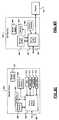
- an exemplary AP 14is shown to include the MAC module 18 and the PHY module 20 .
- the MAC module 18includes a control module 80 that performs control-related operation of the MAC module 18 .
- the control module 80communicates with an asynchronous mode control module 82 that enables and disables asynchronous mode operation of the AP 14 and the client stations 26 .
- the asynchronous mode control module 82generates configuration data for configuring the SUT-enabled client stations and causes the configuration data to be sent to the SUT-enabled client stations.
- the asynchronous mode control module 82may selectively assign the SUT-enabled client stations one or more of the following: a spreading-sequence (i.e., code) to each user; different portions of bandwidth to transmit; and/or different portions of time within the SUT period for transmission.
- the asynchronous mode control module 82also enables the AP 14 to receive asynchronous signals from multiple client stations.
- the SUT-enabled client stationsmay be preconfigured or configured from the client side. In this case, the SUT-enabled client stations may send configuration data to the AP 14 .
- the control module 80also communicates with a client station (CS) power control module 84 that coordinates transmit power levels of the SUT-enabled client stations.
- CSclient station
- the CS power control module 84measures receive power levels of each of the SUT-enabled client stations and selectively adjusts one or more of transmit power levels for the SUT-enabled client stations.
- the AP 14may adjust the power levels such that each SUT-enabled client station has approximately the same receive power levels at the AP 14 .
- the control module 80also communicates with an acknowledgement (ACK) generating module 86 .
- ACKacknowledgement
- the ACK generating module 86generates ACKs at spaced time intervals during the SUT period for each of the SUT-enabled client stations that send SUT data.
- an exemplary client stationis shown to include the MAC module 28 and the PHY module 29 .
- the MAC module 28includes a control module 90 that performs control-related operation of the MAC module 28 .
- the control module 90communicates with a power level adjustment module 92 , which may be implemented in the MAC module 28 or the PHY module 29 .
- the power level adjustment module 92receives transmit power data from the AP 14 and sets a transmit power level of the client station accordingly.
- the control module 90also communicates with an asynchronous mode configuration module 94 that configures the client station to operate in an asynchronous mode.
- the asynchronous mode configuration module 94selectively configures the client station to use one or more of the following: a predetermined spreading-sequence (i.e., code); a predetermined portion of bandwidth to transmit; and/or a predetermined portion of time within the SUT period for transmission.
- FIGS. 6A and 6Bexemplary transmit and receive paths for the client stations and AP are shown, respectively. Skilled artisans will appreciate that there are a number of different ways to implement the foregoing wireless network in addition to those described herein and that the foregoing are merely examples.
- FIG. 6Aan exemplary transmit path 100 of the client station is shown.
- the transmit path 100includes encoder module 110 that receives a bit stream.
- the encoder module 110outputs an encoded bit stream to a spatial mapping module 114 , which performs spatial mapping.
- Outputs of the spatial mapping module 114are input to quadrature amplitude modulation (QAM) mapping modules 116 - 1 , 116 - 2 , . . . , and 116 -P i (collectively QAM mapping modules 118 ), which perform QAM and serial-to-parallel (S/P) conversion.
- the QAM mapping modules 116output OFDM tones that are input to inverse Fast Fourier Transform (IFFT) modules 120 - 1 , 120 - 2 , . . . , 120 -P i (collectively IFFT modules 120 ).
- IFFTinverse Fast Fourier Transform
- Outputs of the IFFT modules 120are input to a parallel-to-serial (P/S) converter and cyclic prefix modules 124 - 11 , 124 - 12 , . . . , 124 -P i (collectively P/S and CP modules 124 ).
- Outputs of the P/S and CP modules 124are input to digital-to-analog converters (DACs) 128 - 1 , 128 - 2 , . . . , and 128 -P i (collectively DACs 128 ) and then to transmitters 134 - 1 , 134 - 2 , . . . , and 134 -P i and associated P i antennas.
- DACsdigital-to-analog converters
- a receive path 148comprises receivers 154 - 1 , 154 - 2 , . . . 154 -M (collectively receivers 154 ) that communicate with analog to digital converters (ADCs) 158 - 1 , 158 - 2 , . . . , and 158 -M (collectively ADCs 158 ).
- ADCsanalog to digital converters
- Outputs of the ADCs 158are input to signal processing modules 159 - 1 , 159 - 2 , . . . , and 159 -W (collectively signal processing modules 159 ).
- Other signal processing modules 159 - 2 , . . . , and 159 -Ware configured for other client stations.
- the signal processing modules 159may be configured by the MAC module to recover signals from one of the client stations.
- the signal processor 159 - 1includes a time/frequency synchronization module 160 , which estimates and corrects for frequency offset and retrieves symbol timing for one of the client stations.
- Outputs of the time/frequency synchronization module 160are input to cyclic prefix (CP) and serial to parallel (SIP) converting modules 164 - 1 , 164 - 2 , . . . , and 164 -M (collectively CP and S/P modules 164 ).
- Outputs of the CP and S/P modules 164are input to Fast Fourier Transform modules 166 - 1 , 166 - 2 , . . . , and 166 -M (collectively FFT 166 ), which perform FFT.
- Outputs of the FFT modules 166are input to a spatial demapping module 170 , which performs spatial demapping.
- Outputs of the spatial demapping module 170are input to a decoder 174 .
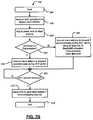
- controlbegins with step 204 .
- controladjusts a transmit power level based on data from the AP.
- the power levelcan be adjusted initially when the client station associates with the AP, at periodic intervals and/or when certain events occur.
- poweris adjusted initially.
- the power levelmay be checked at periodic intervals. If the power level remains about the same (e.g., within a predetermined range of an initial value), the time interval for checking the power level can be increased. This situation may correspond to a client station that is not moving very frequently such as a desktop computer. Conversely, if the power level varies more, the time interval for checking the power level can be reduced. This situation may correspond to a client station that is moving, such as a laptop that is moved. Event-based power level adjustment may also be performed.
- step 212the client station determines whether synchronous transmission is enabled. If step 212 is true, the (SUT-enabled) client station transmits synchronously during an SUT period based on timing data from the AP. Otherwise, the client station transmits asynchronously to the AP during the SUT period using at least one of bandwidth allocation, time allocation and/or code allocation.
- the client stationmay be set up by the AP, by the user, or preset.
- Controldetermines whether there is data that is ready to be sent by the client station to the AP in step 220 . If step 220 is true, control sends the data based on the setup described above in step 224 . After sending data, the client station determines whether an ACK is received in step 226 . If step 226 is true, control returns to step 220 . If step 226 is false, the client station may retransmit in step 228 and then control returns to step 226 .
- step 244the AP reserves SUT periods from legacy client stations as needed.
- step 252the AP adjusts the power levels of the client stations relative to each other based on corresponding receive power levels.
- step 260the AP determines whether synchronous transmission will be used. If step 260 is true, the AP instructs SUT-enabled client stations to transmit synchronously during the SUT period.
- the APinstructs the SUT-enabled client stations to transmit asynchronously during the SUT period using at least one of bandwidth allocation, time allocation and code allocation in step 266 .
- controldetermines whether SUT data is received during the SUT period. If step 268 is true, the AP sends an ACK to the SUT-enabled client stations in step 272 as described above. Control ends in step 276 .
- the present disclosureuses several concepts to improve uplink transmission efficiency.
- multiple client stationsmay transmit simultaneously to the AP.
- the client stationscan transmit either synchronously or asynchronously.
- the client stations and APincrease the ability to separate signals through the use of bandwidth allocation, time allocation, and/or code allocation.
- the present disclosurealso employs power control across client stations in conjunction with SUT to ensure a minimum quality of reception across client stations.
- the present disclosureemploys a protected SUT period during which legacy client stations are blocked from transmitting.
- FIGS. 8A-8Evarious exemplary implementations incorporating the teachings of the present disclosure are shown.
- the SUT-enabled network interfaces of the AP or the client stations described abovecan be integrated with other devices. Some exemplary devices are set forth below.
- the teachings of the disclosurecan be implemented in a wireless network interface of a high definition television (HDTV) 937 .
- the HDTV 937includes an HDTV control module 938 , a display 939 , a power supply 940 , memory 941 , a storage device 942 , a network interface 943 , and an external interface 945 .
- the network interface 943includes a wireless local area network interface, an antenna (not shown) may be included.
- the HDTV 937can receive input signals from the network interface 943 and/or the external interface 945 , which can send and receive data via cable, broadband Internet, and/or satellite.
- the HDTV control module 938may process the input signals, including encoding, decoding, filtering, and/or formatting, and generate output signals.
- the output signalsmay be communicated to one or more of the display 939 , memory 941 , the storage device 942 , the network interface 943 , and the external interface 945 .
- Memory 941may include random access memory (RAM) and/or nonvolatile memory.
- Nonvolatile memorymay include any suitable type of semiconductor or solid-state memory, such as flash memory (including NAND and NOR flash memory), phase change memory, magnetic RAM, and multi-state memory, in which each memory cell has more than two states.
- the storage device 942may include an optical storage drive, such as a DVD drive, and/or a hard disk drive (HDD).
- the HDTV control module 938communicates externally via the network interface 943 and/or the external interface 945 .
- the power supply 940provides power to the components of the HDTV 937 .
- the teachings of the disclosuremay be implemented in a wireless network interface of a vehicle 946 .
- the vehicle 946may include a vehicle control system 947 , a power supply 948 , memory 949 , a storage device 950 , and a network interface 952 . If the network interface 952 includes a wireless local area network interface, an antenna (not shown) may be included.
- the vehicle control system 947may be a powertrain control system, a body control system, an entertainment control system, an anti-lock braking system (ABS), a navigation system, a telematics system, a lane departure system, an adaptive cruise control system, etc.
- the vehicle control system 947may communicate with one or more sensors 954 and generate one or more output signals 956 .
- the sensors 954may include temperature sensors, acceleration sensors, pressure sensors, rotational sensors, airflow sensors, etc.
- the output signals 956may control engine operating parameters, transmission operating parameters, suspension parameters, brake parameters, etc.
- the power supply 948provides power to the components of the vehicle 946 .
- the vehicle control system 947may store data in memory 949 and/or the storage device 950 .
- Memory 949may include random access memory (RAM) and/or nonvolatile memory.
- Nonvolatile memorymay include any suitable type of semiconductor or solid-state memory, such as flash memory (including NAND and NOR flash memory), phase change memory, magnetic RAM, and multi-state memory, in which each memory cell has more than two states.
- the storage device 950may include an optical storage drive, such as a DVD drive, and/or a hard disk drive (HDD).
- the vehicle control system 947may communicate externally using the network interface 952 .
- the teachings of the disclosurecan be implemented in a wireless network interface of a cellular phone 958 .
- the cellular phone 958includes a phone control module 960 , a power supply 962 , memory 964 , a storage device 966 , and a cellular network interface 967 .
- the cellular phone 958may include a network interface 968 , a microphone 970 , an audio output 972 such as a speaker and/or output jack, a display 974 , and a user input device 976 such as a keypad and/or pointing device.
- the network interface 968includes a wireless local area network interface, an antenna (not shown) may be included.
- the phone control module 960may receive input signals from the cellular network interface 967 , the network interface 968 , the microphone 970 , and/or the user input device 976 .
- the phone control module 960may process signals, including encoding, decoding, filtering, and/or formatting, and generate output signals.
- the output signalsmay be communicated to one or more of memory 964 , the storage device 966 , the cellular network interface 967 , the network interface 968 , and the audio output 972 .
- Memory 964may include random access memory (RAM) and/or nonvolatile memory.
- Nonvolatile memorymay include any suitable type of semiconductor or solid-state memory, such as flash memory (including NAND and NOR flash memory), phase change memory, magnetic RAM, and multi-state memory, in which each memory cell has more than two states.
- the storage device 966may include an optical storage drive, such as a DVD drive, and/or a hard disk drive (HDD).
- the power supply 962provides power to the components of the cellular phone 958 .
- the teachings of the disclosurecan be implemented in a wireless network interface of a set top box 978 .
- the set top box 978includes a set top control module 980 , a display 981 , a power supply 982 , memory 983 , a storage device 984 , and a network interface 985 . If the network interface 985 includes a wireless local area network interface, an antenna (not shown) may be included.
- the set top control module 980may receive input signals from the network interface 985 and an external interface 987 , which can send and receive data via cable, broadband Internet, and/or satellite.
- the set top control module 980may process signals, including encoding, decoding, filtering, and/or formatting, and generate output signals.
- the output signalsmay include audio and/or video signals in standard and/or high definition formats.
- the output signalsmay be communicated to the network interface 985 and/or to the display 981 .
- the display 981may include a television, a projector, and/or a monitor.
- the power supply 982provides power to the components of the set top box 978 .
- Memory 983may include random access memory (RAM) and/or nonvolatile memory.
- RAMrandom access memory
- Nonvolatile memorymay include any suitable type of semiconductor or solid-state memory, such as flash memory (including NAND and NOR flash memory), phase change memory, magnetic RAM, and multi-state memory, in which each memory cell has more than two states.
- the storage device 984may include an optical storage drive, such as a DVD drive, and/or a hard disk drive (HDD).
- the teachings of the disclosurecan be implemented in a wireless network interface of a mobile device 989 .
- the mobile device 989may include a mobile device control module 990 , a power supply 991 , memory 992 , a storage device 993 , a network interface 994 , and an external interface 999 .
- the network interface 994includes a wireless local area network interface, an antenna (not shown) may be included.
- the mobile device control module 990may receive input signals from the network interface 994 and/or the external interface 999 .
- the external interface 999may include USB, infrared, and/or Ethernet.
- the input signalsmay include compressed audio and/or video, and may be compliant with the MP3 format.
- the mobile device control module 990may receive input from a user input 996 such as a keypad, touchpad, or individual buttons.
- the mobile device control module 990may process input signals, including encoding, decoding, filtering, and/or formatting, and generate output signals.
- the mobile device control module 990may output audio signals to an audio output 997 and video signals to a display 998 .
- the audio output 997may include a speaker and/or an output jack.
- the display 998may present a graphical user interface, which may include menus, icons, etc.
- the power supply 991provides power to the components of the mobile device 989 .
- Memory 992may include random access memory (RAM) and/or nonvolatile memory.
- Nonvolatile memorymay include any suitable type of semiconductor or solid-state memory, such as flash memory (including NAND and NOR flash memory), phase change memory, magnetic RAM, and multi-state memory, in which each memory cell has more than two states.
- the storage device 993may include an optical storage drive, such as a DVD drive, and/or a hard disk drive (HDD).
- the mobile devicemay include a personal digital assistant, a media player, a laptop computer, a gaming console, or other mobile computing device.
Landscapes
- Engineering & Computer Science (AREA)
- Signal Processing (AREA)
- Computer Networks & Wireless Communication (AREA)
- Mobile Radio Communication Systems (AREA)
Abstract
Description
Claims (30)
Priority Applications (4)
| Application Number | Priority Date | Filing Date | Title |
|---|---|---|---|
| US12/175,501US8149811B2 (en) | 2007-07-18 | 2008-07-18 | Wireless network with simultaneous uplink transmission of independent data from multiple client stations |
| US13/428,282US8958436B2 (en) | 2007-07-18 | 2012-03-23 | Wireless network with simultaneous uplink transmission of independent data from multiple client stations |
| US14/619,652US9294249B2 (en) | 2007-07-18 | 2015-02-11 | Method and apparatus for aggregating acknowledgments transmitted by an access point to a plurality of client stations in a wireless network |
| US15/053,586US9628246B2 (en) | 2007-07-18 | 2016-02-25 | Aggregating acknowledgments transmitted by an access point to a plurality of client stations in a wireless network |
Applications Claiming Priority (3)
| Application Number | Priority Date | Filing Date | Title |
|---|---|---|---|
| US95049407P | 2007-07-18 | 2007-07-18 | |
| US5764408P | 2008-05-30 | 2008-05-30 | |
| US12/175,501US8149811B2 (en) | 2007-07-18 | 2008-07-18 | Wireless network with simultaneous uplink transmission of independent data from multiple client stations |
Related Child Applications (1)
| Application Number | Title | Priority Date | Filing Date |
|---|---|---|---|
| US13/428,282ContinuationUS8958436B2 (en) | 2007-07-18 | 2012-03-23 | Wireless network with simultaneous uplink transmission of independent data from multiple client stations |
Publications (2)
| Publication Number | Publication Date |
|---|---|
| US20090022093A1 US20090022093A1 (en) | 2009-01-22 |
| US8149811B2true US8149811B2 (en) | 2012-04-03 |
Family
ID=40040107
Family Applications (4)
| Application Number | Title | Priority Date | Filing Date |
|---|---|---|---|
| US12/175,501Active2030-11-24US8149811B2 (en) | 2007-07-18 | 2008-07-18 | Wireless network with simultaneous uplink transmission of independent data from multiple client stations |
| US13/428,282Active2028-11-15US8958436B2 (en) | 2007-07-18 | 2012-03-23 | Wireless network with simultaneous uplink transmission of independent data from multiple client stations |
| US14/619,652ActiveUS9294249B2 (en) | 2007-07-18 | 2015-02-11 | Method and apparatus for aggregating acknowledgments transmitted by an access point to a plurality of client stations in a wireless network |
| US15/053,586ActiveUS9628246B2 (en) | 2007-07-18 | 2016-02-25 | Aggregating acknowledgments transmitted by an access point to a plurality of client stations in a wireless network |
Family Applications After (3)
| Application Number | Title | Priority Date | Filing Date |
|---|---|---|---|
| US13/428,282Active2028-11-15US8958436B2 (en) | 2007-07-18 | 2012-03-23 | Wireless network with simultaneous uplink transmission of independent data from multiple client stations |
| US14/619,652ActiveUS9294249B2 (en) | 2007-07-18 | 2015-02-11 | Method and apparatus for aggregating acknowledgments transmitted by an access point to a plurality of client stations in a wireless network |
| US15/053,586ActiveUS9628246B2 (en) | 2007-07-18 | 2016-02-25 | Aggregating acknowledgments transmitted by an access point to a plurality of client stations in a wireless network |
Country Status (5)
| Country | Link |
|---|---|
| US (4) | US8149811B2 (en) |
| EP (1) | EP2183862B1 (en) |
| JP (2) | JP5054193B2 (en) |
| CN (1) | CN101755498B (en) |
| WO (1) | WO2009012448A2 (en) |
Cited By (36)
| Publication number | Priority date | Publication date | Assignee | Title |
|---|---|---|---|---|
| US20110096796A1 (en)* | 2009-10-23 | 2011-04-28 | Hongyuan Zhang | Number of streams indication for wlan |
| US20110103280A1 (en)* | 2009-11-03 | 2011-05-05 | Yong Liu | Power Saving in a Communication Device |
| US20110128929A1 (en)* | 2009-12-02 | 2011-06-02 | Yong Liu | Method and Apparatus for Sounding Multiple Stations |
| US20120177015A1 (en)* | 2007-07-18 | 2012-07-12 | Nabar Rohit U | Wireless Network With Simultaneous Uplink Transmission of Independent Data From Multiple Client Stations |
| US8886755B1 (en) | 2009-12-09 | 2014-11-11 | Marvell International Ltd. | Method and apparatus for facilitating simultaneous transmission from multiple stations |
| US8948150B1 (en) | 2009-05-01 | 2015-02-03 | Marvell International Ltd. | Open loop multiple access for WLAN |
| US8982889B2 (en) | 2008-07-18 | 2015-03-17 | Marvell World Trade Ltd. | Preamble designs for sub-1GHz frequency bands |
| WO2015081187A1 (en) | 2013-11-27 | 2015-06-04 | Marvell Semiconductor, Inc. | Uplink multi-user multiple input multiple output beamforming |
| US9077594B2 (en) | 2009-07-23 | 2015-07-07 | Marvell International Ltd. | Coexistence of a normal-rate physical layer and a low-rate physical layer in a wireless network |
| US20150201432A1 (en)* | 2014-01-15 | 2015-07-16 | Futurewei Technologies, Inc. | System and Method for Uplink OFDMA Transmission |
| US9118530B2 (en) | 2009-07-29 | 2015-08-25 | Marvell World Trade Ltd. | Methods and apparatus for WLAN transmission |
| US9124402B2 (en) | 2007-07-18 | 2015-09-01 | Marvell World Trade Ltd. | Method and apparatus for transmitting first data streams via respective transmitters to multiple clients stations during a same period and successively transmitting second data streams |
| US9209881B2 (en) | 2010-06-16 | 2015-12-08 | Marvell World Trade Ltd. | Alternate feedback types for downlink multiple user MIMO configurations |
| US9215055B2 (en) | 2013-11-27 | 2015-12-15 | Marvell World Trade Ltd. | Medium access protection and bandwidth negotiation in a wireless local area network |
| US9252991B2 (en) | 2010-08-10 | 2016-02-02 | Marvell World Trade Ltd. | Sub-band feedback for beamforming on downlink multiple user MIMO configurations |
| US9397873B2 (en) | 2014-06-11 | 2016-07-19 | Marvell World Trade Ltd. | Compressed orthogonal frequency division multiplexing (OFDM) symbols in a wireless communication system |
| US9473341B2 (en) | 2013-11-27 | 2016-10-18 | Marvell World Trade Ltd. | Sounding and tone block allocation for orthogonal frequency multiple access (OFDMA) in wireless local area networks |
| WO2016201132A1 (en)* | 2015-06-09 | 2016-12-15 | Marvell Semiconductor, Inc. | Channel access for simultaneous uplink transmissons by multiple communication devices |
| US9584383B2 (en) | 2009-07-23 | 2017-02-28 | Marvell World Trade Ltd. | Coexistence of a normal-rate physical layer and a low-rate physical layer in a wireless network |
| US9596060B1 (en) | 2014-05-09 | 2017-03-14 | Marvell International Ltd. | Tone block allocation for orthogonal frequency division multiple access data unit |
| US9629127B2 (en) | 2014-05-02 | 2017-04-18 | Marvell World Trade Ltd. | Multiple user allocation signaling in a wireless communication network |
| US9717086B2 (en) | 2013-11-27 | 2017-07-25 | Marvell World Trade Ltd. | Orthogonal frequency division multiple access for wireless local area network |
| US9825678B2 (en) | 2013-11-26 | 2017-11-21 | Marvell World Trade Ltd. | Uplink multi-user multiple input multiple output for wireless local area network |
| US9832059B2 (en) | 2014-06-02 | 2017-11-28 | Marvell World Trade Ltd. | High efficiency orthogonal frequency division multiplexing (OFDM) physical layer (PHY) |
| US9935794B1 (en) | 2014-03-24 | 2018-04-03 | Marvell International Ltd. | Carrier frequency offset estimation |
| US10079628B2 (en) | 2015-05-27 | 2018-09-18 | Marvell World Trade Ltd. | Signaling resource allocations in multi-user data units |
| US10153857B1 (en) | 2015-04-10 | 2018-12-11 | Marvell International Ltd. | Orthogonal frequency division multiple access protection |
| US10164695B2 (en) | 2014-05-09 | 2018-12-25 | Marvell World Trade Ltd. | Tone block and spatial stream allocation |
| US10257806B2 (en) | 2013-11-11 | 2019-04-09 | Marvell World Trade Ltd. | Medium access control for multi-channel OFDM in a wireless local area network |
| US10368391B1 (en) | 2009-07-23 | 2019-07-30 | Marvell International Ltd. | Midamble for WLAN PHY packets |
| US10541796B2 (en) | 2017-06-09 | 2020-01-21 | Marvell World Trade Ltd. | Packets with midambles having compressed OFDM symbols |
| US10715365B2 (en) | 2017-09-22 | 2020-07-14 | Nxp Usa, Inc. | Determining number of midambles in a packet |
| US20210211903A1 (en)* | 2020-01-02 | 2021-07-08 | Gabriel LAVI | Methods And Systems For Supporting Communication A Plurality Of Client Communication Devices In A Wireless Local Area Network |
| US20230044559A1 (en)* | 2014-03-20 | 2023-02-09 | Interdigital Patent Holdings, Inc. | Method and apparatus for non-orthogonal access in lte systems |
| US12069595B2 (en) | 2014-12-23 | 2024-08-20 | Interdigital Patent Holdings, Inc. | Latency reduction in LTE systems |
| US12408152B2 (en) | 2016-09-28 | 2025-09-02 | Interdigital Patent Holdings, Inc. | Random access in new radio (NR) and other beamforming systems |
Families Citing this family (18)
| Publication number | Priority date | Publication date | Assignee | Title |
|---|---|---|---|---|
| US9924512B1 (en) | 2009-03-24 | 2018-03-20 | Marvell International Ltd. | OFDMA with block tone assignment for WLAN |
| US8571010B1 (en) | 2009-07-21 | 2013-10-29 | Marvell International Ltd. | Simultaneous uplink transmission in a wireless network |
| US9596715B1 (en) | 2009-07-23 | 2017-03-14 | Marvell International Ltd. | Long wireless local area network (WLAN) packets with midambles |
| US8472579B2 (en) | 2010-07-28 | 2013-06-25 | Adc Telecommunications, Inc. | Distributed digital reference clock |
| US8532242B2 (en) | 2010-10-27 | 2013-09-10 | Adc Telecommunications, Inc. | Distributed antenna system with combination of both all digital transport and hybrid digital/analog transport |
| US9319184B2 (en) | 2011-02-01 | 2016-04-19 | Qualcomm Incorporated | Multiple wireless communication device acknowledgements |
| WO2012126081A1 (en) | 2011-03-24 | 2012-09-27 | Research In Motion Limited | Device-empowered radio resource assignment |
| CN103548394B (en) | 2011-03-24 | 2017-02-15 | 黑莓有限公司 | Device-empowered radio resource selection |
| US20140018116A1 (en)* | 2011-03-24 | 2014-01-16 | Research In Motion Limited | Device-empowered radio resource system |
| US9300442B2 (en) | 2011-07-21 | 2016-03-29 | Qualcomm Incorporated | Allowing a rejected wireless communication device access to a communication channel |
| US9351333B1 (en) | 2011-11-30 | 2016-05-24 | Marvell International Ltd. | Long wireless local area network (WLAN) packets with midambles |
| US9584179B2 (en) | 2012-02-23 | 2017-02-28 | Silver Spring Networks, Inc. | System and method for multi-channel frequency hopping spread spectrum communication |
| US20170230149A1 (en)* | 2013-07-11 | 2017-08-10 | InterDigital Pantent Holdings, Inc. | Systems and methods for smart harq for wifi |
| US10230497B2 (en) | 2013-11-01 | 2019-03-12 | Qualcomm Incorporated | Protocols for multiple user frame exchanges |
| US9961510B2 (en)* | 2013-11-01 | 2018-05-01 | Qualcomm Incorporated | Protocols for multiple user frame exchanges |
| JP2018507629A (en)* | 2015-01-30 | 2018-03-15 | 華為技術有限公司Huawei Technologies Co.,Ltd. | Method, terminal, and base station for asynchronous uplink transmission |
| US10554368B2 (en)* | 2015-10-07 | 2020-02-04 | Microsoft Technology Licensing, Llc | Wireless data-acknowledgement communication using frame aggregation |
| US10499269B2 (en) | 2015-11-12 | 2019-12-03 | Commscope Technologies Llc | Systems and methods for assigning controlled nodes to channel interfaces of a controller |
Citations (11)
| Publication number | Priority date | Publication date | Assignee | Title |
|---|---|---|---|---|
| JPH06268575A (en) | 1993-03-12 | 1994-09-22 | Fujitsu Ltd | Channel access method for mobile communication system |
| EP1087630A1 (en) | 1999-09-24 | 2001-03-28 | Alcatel Espana, S.A. | Method for dynamic channel allocation with rearrangement in a TDD/CDMA radio communications system and system therefor |
| US6272117B1 (en)* | 1998-02-20 | 2001-08-07 | Gwcom, Inc. | Digital sensing multi access protocol |
| US20010038619A1 (en)* | 2000-04-07 | 2001-11-08 | Philips Corporation | Radio communication system and method of operating the system |
| US20020150058A1 (en) | 2000-11-02 | 2002-10-17 | Samsung Electronics Co., Ltd. | Apparatus and method for randomly controlling time slot of sub-frame in an NB-TDD CDMA system |
| US6594251B1 (en)* | 1999-07-06 | 2003-07-15 | Cisco Technology Inc. | Polling for transmission power control |
| US20050195786A1 (en)* | 2002-08-07 | 2005-09-08 | Extricom Ltd. | Spatial reuse of frequency channels in a WLAN |
| US7289481B2 (en)* | 2004-03-24 | 2007-10-30 | Wavion Ltd. | WLAN capacity enhancement by contention resolution |
| US7394787B2 (en)* | 2002-12-30 | 2008-07-01 | Sk Telecom Co., Ltd. | Method and system for preventing call drop by restricting overhead message updated in 1X system during 1xEV-DO traffic state |
| US7636328B2 (en)* | 2004-10-20 | 2009-12-22 | Qualcomm Incorporated | Efficient transmission of signaling using channel constraints |
| US7873049B2 (en)* | 2006-06-28 | 2011-01-18 | Hitachi, Ltd. | Multi-user MAC protocol for a local area network |
Family Cites Families (160)
| Publication number | Priority date | Publication date | Assignee | Title |
|---|---|---|---|---|
| JPS62176235A (en) | 1986-01-29 | 1987-08-03 | Toshiba Corp | Data communication system |
| JPS62176235U (en) | 1986-04-28 | 1987-11-09 | ||
| JPS6421059A (en) | 1987-07-15 | 1989-01-24 | Mitsubishi Motors Corp | Production of plated sheet vapor-deposited with metal |
| JPS6421059U (en) | 1987-07-29 | 1989-02-02 | ||
| US5539394A (en) | 1994-03-16 | 1996-07-23 | International Business Machines Corporation | Time division multiplexed batch mode item identification system |
| WO1999004519A2 (en) | 1997-07-16 | 1999-01-28 | At & T Corp. | Combined array processing and space-time coding |
| JPH11275056A (en) | 1998-03-23 | 1999-10-08 | Sony Corp | Device and method for transmission rate estimate |
| US7046746B1 (en) | 2001-03-19 | 2006-05-16 | Cisco Systems Wireless Networking (Australia) Pty Limited | Adaptive Viterbi decoder for a wireless data network receiver |
| US20020174172A1 (en) | 2001-03-29 | 2002-11-21 | Hatalkar Atul N. | Mechanism to control compilation and communication of the client-device profile by using unidirectional messaging over a broadcast channel |
| US6754195B2 (en) | 2001-07-06 | 2004-06-22 | Intersil Americas Inc. | Wireless communication system configured to communicate using a mixed waveform configuration |
| DE60104113T2 (en)* | 2001-08-22 | 2004-10-28 | Matsushita Electric Industrial Co., Ltd., Kadoma | Transmission method and transmission device with multi-channel ARQ |
| KR100450936B1 (en) | 2001-08-27 | 2004-10-02 | 삼성전자주식회사 | Apparatus for generating preamble sequence in broadband wireless access communication system using orthogonal frequency division multiplexing scheme and method thereof |
| US7161987B2 (en) | 2001-09-26 | 2007-01-09 | Conexant, Inc. | Single-carrier to multi-carrier wireless architecture |
| JP3975069B2 (en)* | 2001-10-25 | 2007-09-12 | 株式会社エヌ・ティ・ティ・ドコモ | Radio base station and radio communication control method |
| US20030125040A1 (en) | 2001-11-06 | 2003-07-03 | Walton Jay R. | Multiple-access multiple-input multiple-output (MIMO) communication system |
| US6760388B2 (en) | 2001-12-07 | 2004-07-06 | Qualcomm Incorporated | Time-domain transmit and receive processing with channel eigen-mode decomposition for MIMO systems |
| US7020110B2 (en) | 2002-01-08 | 2006-03-28 | Qualcomm Incorporated | Resource allocation for MIMO-OFDM communication systems |
| US7471667B2 (en) | 2002-01-09 | 2008-12-30 | Nxp B.V. | Coexistence of modulation schemes in a WLAN |
| DE60332893D1 (en) | 2002-04-25 | 2010-07-22 | Imec | CDMA Reception Transmission Techniques for Radio Systems with Multiple Inputs and Multiple Outputs (MIMO) |
| US7248625B2 (en) | 2002-09-05 | 2007-07-24 | Silicon Storage Technology, Inc. | Compensation of I-Q imbalance in digital transceivers |
| US6873606B2 (en) | 2002-10-16 | 2005-03-29 | Qualcomm, Incorporated | Rate adaptive transmission scheme for MIMO systems |
| KR100900970B1 (en) | 2002-10-19 | 2009-06-08 | 삼성전자주식회사 | Mobile communication device and method including base station / mobile station multi-antenna |
| US8320301B2 (en) | 2002-10-25 | 2012-11-27 | Qualcomm Incorporated | MIMO WLAN system |
| US7324429B2 (en) | 2002-10-25 | 2008-01-29 | Qualcomm, Incorporated | Multi-mode terminal in a wireless MIMO system |
| KR100539854B1 (en) | 2003-01-09 | 2005-12-28 | 삼성전자주식회사 | Apparatus for transmitting/receiving data to achieve multiplex gain and diversity gain at the same time in mobile communication system using space-time trellis code and method thereof |
| JP4095612B2 (en) | 2003-03-18 | 2008-06-04 | 富士通株式会社 | Transmission power control device |
| US7916803B2 (en) | 2003-04-10 | 2011-03-29 | Qualcomm Incorporated | Modified preamble structure for IEEE 802.11a extensions to allow for coexistence and interoperability between 802.11a devices and higher data rate, MIMO or otherwise extended devices |
| US7317687B2 (en)* | 2003-06-12 | 2008-01-08 | Koninklijke Philips Electronics N.V. | Transmitting data frames with less interframe space (ifs) time |
| JP4195716B2 (en) | 2003-06-27 | 2008-12-10 | ノキア コーポレイション | Method and apparatus for packet aggregation in a wireless communication network |
| US7039412B2 (en) | 2003-08-08 | 2006-05-02 | Intel Corporation | Method and apparatus for transmitting wireless signals on multiple frequency channels in a frequency agile network |
| JP2005102136A (en) | 2003-08-15 | 2005-04-14 | Sony Corp | Wireless communication system, wireless communication apparatus, wireless communication method, and computer program |
| US7447232B2 (en) | 2003-09-30 | 2008-11-04 | Intel Corporation | Data burst transmission methods in WLAN devices and systems |
| US8483105B2 (en) | 2003-10-15 | 2013-07-09 | Qualcomm Incorporated | High speed media access control |
| KR100574960B1 (en) | 2003-11-25 | 2006-05-02 | 삼성전자주식회사 | Frame Segmentation in Payload |
| US20060007898A1 (en) | 2003-12-23 | 2006-01-12 | Maltsev Alexander A | Method and apparatus to provide data packet |
| BRPI0418324B1 (en) | 2004-01-08 | 2018-10-09 | Sony Corp | wireless communication system, device and method |
| US8194771B2 (en) | 2004-01-27 | 2012-06-05 | Agere Systems Inc. | Transmission method and apparatus in a multiple antenna communication system |
| KR100959123B1 (en) | 2004-02-11 | 2010-05-25 | 삼성전자주식회사 | Wireless network communication method |
| JP4040585B2 (en) | 2004-02-19 | 2008-01-30 | 日本電信電話株式会社 | Communication system and communication method using adaptive array antenna |
| JP4528541B2 (en)* | 2004-03-05 | 2010-08-18 | 株式会社東芝 | COMMUNICATION DEVICE, COMMUNICATION METHOD, AND COMMUNICATION SYSTEM |
| US7535978B2 (en) | 2004-04-02 | 2009-05-19 | Broadcom Corporation | Accurate signal detection in a wireless environment |
| US7411898B2 (en) | 2004-05-10 | 2008-08-12 | Infineon Technologies Ag | Preamble generator for a multiband OFDM transceiver |
| KR20070020033A (en) | 2004-05-13 | 2007-02-16 | 코닌클리케 필립스 일렉트로닉스 엔.브이. | Multiple receiver set (MRA) with different data rates for IEEE 802.11N |
| KR20050109863A (en) | 2004-05-17 | 2005-11-22 | 삼성전자주식회사 | Dynamic subchannel and bit allocation in multiuser mimo/ofdma system |
| DK1751890T3 (en) | 2004-05-27 | 2017-06-12 | Qualcomm Inc | MODIFIED INTRODUCTION STRUCTURE FOR IEEE 802.11A EXTENSIONS TO ENABLE CO-EXISTENCE AND INTEROPERABILITY BETWEEN 802.11A DEVICES AND HIGHER DATARATES, MIMO OR OTHER EXTENDED DEVICES |
| JP4256301B2 (en) | 2004-05-28 | 2009-04-22 | 株式会社東芝 | Wireless communication device |
| US8619907B2 (en) | 2004-06-10 | 2013-12-31 | Agere Systems, LLC | Method and apparatus for preamble training in a multiple antenna communication system |
| US7839834B2 (en) | 2004-06-18 | 2010-11-23 | Qualcomm Incorporated | Radio link protocols for a wireless communication system |
| JP2008503965A (en) | 2004-06-24 | 2008-02-07 | コーニンクレッカ フィリップス エレクトロニクス エヌ ヴィ | Super frame with improved data transmission efficiency |
| MX2007001704A (en) | 2004-08-12 | 2007-04-12 | Interdigital Tech Corp | Method and system for controlling access to a wireless communication medium. |
| KR100608006B1 (en)* | 2004-08-31 | 2006-08-02 | 삼성전자주식회사 | Data transmission methods in wireless LAN, access point device and station device |
| US7436903B2 (en) | 2004-09-29 | 2008-10-14 | Intel Corporation | Multicarrier transmitter and method for transmitting multiple data streams with cyclic delay diversity |
| JP4536780B2 (en) | 2004-11-05 | 2010-09-01 | 株式会社エヌ・ティ・ティ・ドコモ | Multi-user transmission system |
| JP2006140927A (en) | 2004-11-15 | 2006-06-01 | Sanyo Electric Co Ltd | Radio apparatus, and method and program for controlling transmission |
| JP4482433B2 (en) | 2004-11-19 | 2010-06-16 | Okiセミコンダクタ株式会社 | Wireless communication apparatus and communication method thereof |
| JP2008521322A (en)* | 2004-11-22 | 2008-06-19 | コーニンクレッカ フィリップス エレクトロニクス エヌ ヴィ | Method and apparatus for separating radio stations in a wireless network |
| KR100590896B1 (en)* | 2004-11-26 | 2006-06-19 | 삼성전자주식회사 | Media access method for competition and no competition |
| KR100918761B1 (en) | 2005-01-06 | 2009-09-24 | 삼성전자주식회사 | Gain Factor Setting Method for Uplink Service in Wireless Communication System |
| WO2006092465A1 (en)* | 2005-03-04 | 2006-09-08 | Nokia Corporation | Link establishment in a wireless communication environment |
| JP2006254235A (en) | 2005-03-11 | 2006-09-21 | Matsushita Electric Ind Co Ltd | Wireless transmission device and wireless reception device |
| GB2424805B (en) | 2005-03-30 | 2007-02-28 | Toshiba Res Europ Ltd | Efficient channel tracking in packet based OFDM systems |
| JP4802830B2 (en) | 2005-04-11 | 2011-10-26 | パナソニック株式会社 | Terminal device |
| JP2006295736A (en) | 2005-04-13 | 2006-10-26 | Mitsubishi Electric Corp | Wireless communication apparatus and communication method |
| US20060233271A1 (en) | 2005-04-14 | 2006-10-19 | Savas Alpaslan G | Method and apparatus for channel estimation in distributed transmit diversity systems |
| US8634432B2 (en) | 2005-05-06 | 2014-01-21 | Samsung Electronics Co., Ltd. | System and method for subcarrier allocation in a multicarrier wireless network |
| JP4611805B2 (en) | 2005-05-27 | 2011-01-12 | Kddi株式会社 | Radio communication system, radio base station apparatus, transmission power control method, and antenna directivity control method |
| KR100643299B1 (en) | 2005-06-09 | 2006-11-10 | 삼성전자주식회사 | Method and apparatus for transmitting and receiving legacy data in high speed wireless network |
| TWI339540B (en) | 2005-06-09 | 2011-03-21 | Samsung Electronics Co Ltd | Method and apparatus for transmitting data with down compatibility in high throughput wireless network |
| US7855993B2 (en) | 2005-08-23 | 2010-12-21 | Agere Systems Inc. | Method and apparatus for reducing power fluctuations during preamble training in a multiple antenna communication system using cyclic delays |
| US7742390B2 (en) | 2005-08-23 | 2010-06-22 | Agere Systems Inc. | Method and apparatus for improved long preamble formats in a multiple antenna communication system |
| US7711061B2 (en) | 2005-08-24 | 2010-05-04 | Broadcom Corporation | Preamble formats supporting high-throughput MIMO WLAN and auto-detection |
| US20070060155A1 (en) | 2005-08-31 | 2007-03-15 | Emanuel Kahana | System and method to dynamically adapt a CCA threshold |
| US7776817B2 (en) | 2005-09-02 | 2010-08-17 | Morehouse School Of Medicine | Neuregulins for prevention and treatment of damage from acute assault on vascular and neuronal tissue and as regulators of neuronal stem cell migration |
| JP4841333B2 (en) | 2005-09-19 | 2011-12-21 | 三洋電機株式会社 | Wireless device and communication system using the same |
| CN1937603A (en)* | 2005-09-20 | 2007-03-28 | 株式会社Ntt都科摩 | Communication method based on sub-carrier distribution manner and communication system |
| JP4504293B2 (en) | 2005-09-29 | 2010-07-14 | 株式会社東芝 | Wireless communication apparatus, wireless communication system, and wireless communication method provided with multiple antennas |
| WO2007043108A1 (en) | 2005-09-30 | 2007-04-19 | Mitsubishi Denki Kabushiki Kaisha | Wireless communication system and wireless communication method |
| JP4624901B2 (en) | 2005-10-12 | 2011-02-02 | 株式会社日立製作所 | Wireless data communication system, wireless data communication method, and communication apparatus |
| JP2007110456A (en) | 2005-10-14 | 2007-04-26 | Hitachi Ltd | Wireless communication device |
| JP4602225B2 (en) | 2005-10-28 | 2010-12-22 | 三菱電機株式会社 | Wireless communication apparatus and multi-user MIMO system |
| US7804917B2 (en) | 2005-11-07 | 2010-09-28 | Sigma Designs, Inc. | Clear channel assessment method and system for ultra wideband OFDM |
| SG166823A1 (en) | 2005-11-07 | 2010-12-29 | Agency Science Tech & Res | Method and system for transmitting a signal to a communication device in a cellular communication system |
| US8910027B2 (en) | 2005-11-16 | 2014-12-09 | Qualcomm Incorporated | Golay-code generation |
| JP4885978B2 (en)* | 2005-12-23 | 2012-02-29 | エルジー エレクトロニクス インコーポレイティド | Method and procedure for asynchronous, synchronous and synchronous waiting communication in an E-UTRA system |
| US7706376B2 (en) | 2005-12-30 | 2010-04-27 | Intel Corporation | System and method for communicating with mobile stations over an extended range in a wireless local area network |
| US7933357B2 (en) | 2006-02-21 | 2011-04-26 | Samsung Electronics Co., Ltd | Apparatus and method for transmission and reception in a multi-user MIMO communication system |
| US8179871B2 (en) | 2006-03-29 | 2012-05-15 | Samsung Electronics Co., Ltd. | Method and system for channel access control for transmission of video information over wireless channels |
| US8542589B2 (en) | 2006-06-05 | 2013-09-24 | Qualcomm Incorporated | Method and apparatus for providing beamforming feedback in wireless communication systems |
| US20070286122A1 (en) | 2006-06-12 | 2007-12-13 | Motorola, Inc. | Clear channel assessment threshold adaptation in a wireless network |
| EP1895703A1 (en) | 2006-07-05 | 2008-03-05 | Koninklijke Philips Electronics N.V. | Bandwidth asymmetric communication system based on OFDM and TDMA |
| US8126090B1 (en) | 2006-08-30 | 2012-02-28 | Marvell International Ltd. | Channel estimation for a WLAN through increased use of preamble |
| UA94482C2 (en) | 2006-10-03 | 2011-05-10 | Квелкомм Інкорпорейтед | Synchronization transmission in a wireless communication system |
| US8332732B2 (en) | 2006-11-30 | 2012-12-11 | Qualcomm Incorporated | Common air interface supporting single carrier and OFDM |
| CN101237604B (en) | 2007-01-30 | 2011-06-15 | 展讯通信(上海)有限公司 | Single-frequency networking method in TD-SCDMA system |
| US7924766B2 (en)* | 2007-04-10 | 2011-04-12 | Mitsubishi Electric Research Labs, Inc. | Hybrid multiple access method and system in wireless networks |
| US7974225B2 (en) | 2007-05-30 | 2011-07-05 | Intel Corporation | Providing extended range modes as part of the 802.11n standard |
| CN101755391B (en) | 2007-07-18 | 2013-08-07 | 马维尔国际贸易有限公司 | Access point with simultaneous downlink transmission of independent data for multiple client stations |
| US8149811B2 (en)* | 2007-07-18 | 2012-04-03 | Marvell World Trade Ltd. | Wireless network with simultaneous uplink transmission of independent data from multiple client stations |
| KR101421592B1 (en) | 2007-09-05 | 2014-08-14 | 삼성전자주식회사 | Apparatus and method for transmitting and receiving in interleaver division multiple access system |
| US8576821B2 (en) | 2007-10-31 | 2013-11-05 | Qualcomm Incorporated | Method and apparatus for improved data demodulation in a wireless communication network |
| KR100918500B1 (en) | 2007-12-03 | 2009-09-24 | 한국전자통신연구원 | Method and apparatus of channel estimation |
| WO2009099949A2 (en) | 2008-02-01 | 2009-08-13 | Marvell World Trade Ltd. | Channel sounding and estimation strategies for antenna selection in mimo systems |
| EP2263407B1 (en) | 2008-03-04 | 2016-05-11 | Koninklijke Philips N.V. | Signaling of transmission settings in multi-user systems |
| US8213395B2 (en) | 2008-03-11 | 2012-07-03 | Broadcom Corporation | Method and system for dual mode operation in wireless networks |
| JP4626669B2 (en) | 2008-04-14 | 2011-02-09 | ソニー株式会社 | Transmission device, communication system, transmission method, and program |
| US8175118B2 (en) | 2008-05-15 | 2012-05-08 | Marvell World Trade Ltd. | Efficient physical layer preamble format |
| EP2301183A1 (en) | 2008-07-08 | 2011-03-30 | Marvell World Trade Ltd. | Physical layer frame format design for wideband wireless communications systems |
| US8982889B2 (en) | 2008-07-18 | 2015-03-17 | Marvell World Trade Ltd. | Preamble designs for sub-1GHz frequency bands |
| US8155138B2 (en) | 2008-08-19 | 2012-04-10 | Qualcomm Incorporated | Training sequences for very high throughput wireless communication |
| US20100046656A1 (en) | 2008-08-20 | 2010-02-25 | Qualcomm Incorporated | Preamble extensions |
| US20100290449A1 (en) | 2008-08-20 | 2010-11-18 | Qualcomm Incorporated | Preamble extensions |
| US8411807B1 (en) | 2008-09-02 | 2013-04-02 | Cisco Technology, Inc. | Mid-packet clear channel assessment |
| KR101497928B1 (en) | 2008-09-25 | 2015-03-03 | 삼성전자주식회사 | Apparatus for transmitting and receiving signal in multi-input multi-output system, and mehtod the same |
| JP2010093704A (en) | 2008-10-10 | 2010-04-22 | Sony Corp | Radio communication system, radio communication device and radio communication method, and computer program |
| JP4631956B2 (en) | 2008-10-14 | 2011-02-16 | ソニー株式会社 | Wireless communication apparatus and wireless communication method |
| KR101105399B1 (en) | 2008-12-22 | 2012-01-17 | 한국전자통신연구원 | Apparatus, Method and Receiver for Time Synchronization Detection in Orthogonal Frequency Division Multiple Access System |
| US7986613B2 (en) | 2008-12-27 | 2011-07-26 | Intel Corporation | Downlink subchannelization scheme for 802.16M |
| WO2010095793A1 (en) | 2009-02-18 | 2010-08-26 | Lg Electronics Inc. | Channel access method for very high throughput (vht) wireless local access network system |
| JP5328059B2 (en) | 2009-02-18 | 2013-10-30 | エルジー エレクトロニクス インコーポレイティド | Coexistence channel access method |
| JP5287346B2 (en) | 2009-02-26 | 2013-09-11 | 株式会社デンソー | Communication device |
| US8135015B2 (en) | 2009-03-27 | 2012-03-13 | Qualcomm Incorporated | System and method of transmitting and receiving data frames |
| CN102396186B (en) | 2009-04-13 | 2014-12-10 | 马维尔国际贸易有限公司 | Physical layer frame format for wlan |
| US8599803B1 (en) | 2009-05-01 | 2013-12-03 | Marvell International Ltd. | Open loop multiple access for WLAN |
| US8437440B1 (en) | 2009-05-28 | 2013-05-07 | Marvell International Ltd. | PHY frame formats in a system with more than four space-time streams |
| US9197298B2 (en) | 2009-06-05 | 2015-11-24 | Broadcom Corporation | Group identification and definition within multiple user, multiple access, and/or MIMO wireless communications |
| US8526351B2 (en) | 2009-06-05 | 2013-09-03 | Broadcom Corporation | Channel characterization and training within multiple user, multiple access, and/or MIMO wireless communications |
| US8885535B2 (en) | 2009-06-05 | 2014-11-11 | Broadcom Corporation | Management frame map directed operational parameters within multiple user, multiple access, and/or MIMO wireless communications |
| US8761230B2 (en) | 2009-06-08 | 2014-06-24 | Adeptence, Llc | Method and apparatus for continuous phase modulation preamble encoding and decoding |
| US8498252B2 (en) | 2009-07-06 | 2013-07-30 | Intel Corporation | Midamble for wireless networks |
| US9088466B2 (en) | 2009-07-23 | 2015-07-21 | Marvell World Trade Ltd. | Coexistence of a normal-rate physical layer and a low-rate physical layer in a wireless network |
| US8462863B1 (en) | 2009-07-23 | 2013-06-11 | Marvell International Ltd. | Midamble for WLAN PHY frames |
| KR101657255B1 (en) | 2009-07-29 | 2016-09-13 | 마벨 월드 트레이드 리미티드 | Methods and apparatus for wlan transmission |
| US8599804B2 (en) | 2009-08-07 | 2013-12-03 | Broadcom Corporation | Distributed signal field for communications within multiple user, multiple access, and/or MIMO wireless communications |
| US9935805B2 (en) | 2009-08-25 | 2018-04-03 | Qualcomm Incorporated | MIMO and MU-MIMO OFDM preambles |
| KR20110027533A (en) | 2009-09-09 | 2011-03-16 | 엘지전자 주식회사 | Method and device for transmitting control information in multi-antenna system |
| KR20110036485A (en) | 2009-10-01 | 2011-04-07 | 엘지전자 주식회사 | Method and apparatus for data transmission in wireless LAN system |
| KR101422039B1 (en) | 2009-10-21 | 2014-07-23 | 엘지전자 주식회사 | Method and apparatus for scanning existing networks in tvws |
| CN102668405B (en) | 2009-10-23 | 2015-12-02 | 马维尔国际贸易有限公司 | For the stream instruction number of WLAN |
| US9288096B2 (en) | 2009-12-07 | 2016-03-15 | Qualcomm Incorporated | Enabling phase tracking for a communication device |
| EP2471200A4 (en) | 2009-12-10 | 2012-10-17 | Lg Electronics Inc | Method and apparatus of transmitting training signal in wireless local area network system |
| US8238316B2 (en) | 2009-12-22 | 2012-08-07 | Intel Corporation | 802.11 very high throughput preamble signaling field with legacy compatibility |
| KR101478040B1 (en) | 2010-02-23 | 2015-01-06 | 한국전자통신연구원 | Method and apparatus for transmitting/receiving data |
| EP3783822B1 (en) | 2010-03-11 | 2024-12-25 | Electronics and Telecommunications Research Institute | Method and apparatus for transceiving data in a mimo system |
| DE102010013725A1 (en) | 2010-03-31 | 2011-10-06 | Gdf Suez | Method for creating a horizontal well in the ground and horizontal drilling device |
| US8982686B2 (en) | 2010-06-07 | 2015-03-17 | Qualcomm Incorporated | Communication devices for generating and using a matrix-mapped sequence |
| US8619655B2 (en) | 2010-06-09 | 2013-12-31 | Broadcom Corporation | Cyclic shift delay (CSD) short training field (STF) for orthogonal frequency division multiplexing (OFDM) signaling within multiple user, multiple access, and/or MIMO wireless communicaitons |
| US8718169B2 (en) | 2010-06-15 | 2014-05-06 | Qualcomm Incorporated | Using a field format on a communication device |
| US9021341B1 (en) | 2010-06-16 | 2015-04-28 | Marvell International Ltd. | LDPC coding in a communication system |
| CN103053123B (en) | 2010-08-10 | 2016-06-01 | 马维尔国际贸易有限公司 | Channel Description Feedback in Communication Systems |
| JP5936280B2 (en) | 2011-01-28 | 2016-06-22 | マーベル ワールド トレード リミテッド | Long-distance wireless LAN physical layer frame format |
| US9130727B2 (en) | 2011-02-04 | 2015-09-08 | Marvell World Trade Ltd. | Control mode PHY for WLAN |
| US8625690B2 (en) | 2011-03-04 | 2014-01-07 | Qualcomm Incorporated | Systems and methods for wireless communication in sub gigahertz bands |
| TWI416240B (en) | 2011-03-30 | 2013-11-21 | Largan Precision Co Ltd | Photographing module |
| US8731590B2 (en) | 2011-05-24 | 2014-05-20 | Broadcom Corporation | Resource allocation control |
| JP6014948B2 (en) | 2011-05-26 | 2016-10-26 | マーベル ワールド トレード リミテッド | Sounding packet format for long distance WLAN |
| US8797881B2 (en) | 2011-06-13 | 2014-08-05 | Cisco Technology, Inc. | Coexistence mechanism for multiple channels |
| US8902869B2 (en) | 2011-06-15 | 2014-12-02 | Marvell World Trade Ltd. | Low bandwidth PHY for WLAN |
| CN103765973B (en) | 2011-08-29 | 2017-11-10 | 马维尔国际贸易有限公司 | Normal speed physical layer and low rate physical layer coexisting in the wireless network |
| KR102276433B1 (en) | 2012-02-07 | 2021-07-12 | 마벨 월드 트레이드 리미티드 | Pilot sequence design for long range wlan |
| US9335789B2 (en) | 2013-05-10 | 2016-05-10 | Adam Merzon | System and apparatus for mounting a handheld electronic device |
- 2008
- 2008-07-18USUS12/175,501patent/US8149811B2/enactiveActive
- 2008-07-18EPEP08782054.4Apatent/EP2183862B1/enactiveActive
- 2008-07-18CNCN200880025080.9Apatent/CN101755498B/enactiveActive
- 2008-07-18JPJP2010517185Apatent/JP5054193B2/enactiveActive
- 2008-07-18WOPCT/US2008/070469patent/WO2009012448A2/enactiveApplication Filing
- 2012
- 2012-03-23USUS13/428,282patent/US8958436B2/enactiveActive
- 2012-07-26JPJP2012165994Apatent/JP5598800B2/enactiveActive
- 2015
- 2015-02-11USUS14/619,652patent/US9294249B2/enactiveActive
- 2016
- 2016-02-25USUS15/053,586patent/US9628246B2/enactiveActive
Patent Citations (11)
| Publication number | Priority date | Publication date | Assignee | Title |
|---|---|---|---|---|
| JPH06268575A (en) | 1993-03-12 | 1994-09-22 | Fujitsu Ltd | Channel access method for mobile communication system |
| US6272117B1 (en)* | 1998-02-20 | 2001-08-07 | Gwcom, Inc. | Digital sensing multi access protocol |
| US6594251B1 (en)* | 1999-07-06 | 2003-07-15 | Cisco Technology Inc. | Polling for transmission power control |
| EP1087630A1 (en) | 1999-09-24 | 2001-03-28 | Alcatel Espana, S.A. | Method for dynamic channel allocation with rearrangement in a TDD/CDMA radio communications system and system therefor |
| US20010038619A1 (en)* | 2000-04-07 | 2001-11-08 | Philips Corporation | Radio communication system and method of operating the system |
| US20020150058A1 (en) | 2000-11-02 | 2002-10-17 | Samsung Electronics Co., Ltd. | Apparatus and method for randomly controlling time slot of sub-frame in an NB-TDD CDMA system |
| US20050195786A1 (en)* | 2002-08-07 | 2005-09-08 | Extricom Ltd. | Spatial reuse of frequency channels in a WLAN |
| US7394787B2 (en)* | 2002-12-30 | 2008-07-01 | Sk Telecom Co., Ltd. | Method and system for preventing call drop by restricting overhead message updated in 1X system during 1xEV-DO traffic state |
| US7289481B2 (en)* | 2004-03-24 | 2007-10-30 | Wavion Ltd. | WLAN capacity enhancement by contention resolution |
| US7636328B2 (en)* | 2004-10-20 | 2009-12-22 | Qualcomm Incorporated | Efficient transmission of signaling using channel constraints |
| US7873049B2 (en)* | 2006-06-28 | 2011-01-18 | Hitachi, Ltd. | Multi-user MAC protocol for a local area network |
Non-Patent Citations (8)
| Title |
|---|
| IEEE 802.11n; IEEE 802.11-04/0889r6; IEEE P802.11 Wireless LANs; TGn Sync Proposal Technical Specification; Syed Aon Mujtaba; Agere Systems Inc.; May 18, 2005; 131 pages. |
| IEEE P802.11g/D8.2, Apr. 2003 (Supplement to ANSI/IEEE Std 802.11-1999(Reaff 2003)); DRAFT Supplement to STANDARD [for] Information Technology-Telecommunications and information exchange between systems-Local and metropolitan area networks-Specific requirements-Part 11: Wireless LAN Medium Access Control (MAC) and Physical Layer (PHY) specifications: Further Higher Data Rate Extension in the 2.4 GHz Band; LAN/MAN Standards Committee of the IEEE Computer Society; 69 pages. |
| IEEE Std 802.11a-1999 (Supplement to IEEE Std 802.11-1999); Supplement to IEEE Standard for Information technology-Telecommunications and information exchange between systems-Local and metropolitan area networks-Specific requirements-Part 11: Wireless LAN Medium Access Control (MAC) and Physical Layer (PHY) specifications: High-speed Physical Layer in the 5 GHz Band; LAN/MAN Standards Committee of the IEEE Computer Society; Sep. 16, 1999; 91 pages. |
| IEEE Std 802.11b-1999 (Supplement to IEEE Std 802.11-1999 Edition); Supplement to IEEE Standard for Information technology-Telecommunications and information exchange between systems-Local and metropolitan area networks-Specific requirements-Part 11: Wireless LAN Medium Access Control (MAC) and Physical Layer (PHY) specifications: Higher-Speed Physical Layer Extension in the 2.4 GHz Band; LAN/MAN Standards Committee of the IEEE Computer Society; Sep. 16, 1999 IEEE-SA Standards Board; 96 pages. |
| Invitation to Pay Additional Fees and, where Applicable, Protest Fee dated Jan. 21, 2009 in reference to PCT/US2008/070469. |
| Second Office Action in corresponding European Patent Application No. 08 782 054.4, dated Feb. 3, 2011. |
| The International Search Report and the Written Opinion of the International Searching Authority, or the Declaration mailed Mar. 11, 2009 for International Application No. PCT/US2008/070469 filed Jul. 18, 2008; 15 pages. |
| U.S. Appl. No. 12/175,526, filed Jul. 18, 2008, Rohit U. Nabar et al. |
Cited By (96)
| Publication number | Priority date | Publication date | Assignee | Title |
|---|---|---|---|---|
| US9124402B2 (en) | 2007-07-18 | 2015-09-01 | Marvell World Trade Ltd. | Method and apparatus for transmitting first data streams via respective transmitters to multiple clients stations during a same period and successively transmitting second data streams |
| US9480064B2 (en) | 2007-07-18 | 2016-10-25 | Marvell World Trade Ltd. | Method and apparatus for transmitting first data streams via respective transmitters to multiple client stations during a same period and successively transmitting second data streams |
| US9628246B2 (en) | 2007-07-18 | 2017-04-18 | Marvell World Trade Ltd. | Aggregating acknowledgments transmitted by an access point to a plurality of client stations in a wireless network |
| US20120177015A1 (en)* | 2007-07-18 | 2012-07-12 | Nabar Rohit U | Wireless Network With Simultaneous Uplink Transmission of Independent Data From Multiple Client Stations |
| US9294249B2 (en) | 2007-07-18 | 2016-03-22 | Marvell World Trade Ltd. | Method and apparatus for aggregating acknowledgments transmitted by an access point to a plurality of client stations in a wireless network |
| US8958436B2 (en)* | 2007-07-18 | 2015-02-17 | Marvell World Trade Ltd. | Wireless network with simultaneous uplink transmission of independent data from multiple client stations |
| US8982889B2 (en) | 2008-07-18 | 2015-03-17 | Marvell World Trade Ltd. | Preamble designs for sub-1GHz frequency bands |
| US8948150B1 (en) | 2009-05-01 | 2015-02-03 | Marvell International Ltd. | Open loop multiple access for WLAN |
| US11006480B1 (en) | 2009-07-23 | 2021-05-11 | Marvell Asia Pte, Ltd. | Midamble for WLAN PHY packets |
| US9860823B2 (en) | 2009-07-23 | 2018-01-02 | Marvell International Ltd. | Method and apparatus for reducing interference between wireless devices operating at different data rates in a wireless network |
| US9713065B2 (en) | 2009-07-23 | 2017-07-18 | Marvell World Trade Ltd. | Coexistence of devices operating at different data rates in wireless networks |
| US10368391B1 (en) | 2009-07-23 | 2019-07-30 | Marvell International Ltd. | Midamble for WLAN PHY packets |
| US9077594B2 (en) | 2009-07-23 | 2015-07-07 | Marvell International Ltd. | Coexistence of a normal-rate physical layer and a low-rate physical layer in a wireless network |
| US9584383B2 (en) | 2009-07-23 | 2017-02-28 | Marvell World Trade Ltd. | Coexistence of a normal-rate physical layer and a low-rate physical layer in a wireless network |
| US9088466B2 (en) | 2009-07-23 | 2015-07-21 | Marvell World Trade Ltd. | Coexistence of a normal-rate physical layer and a low-rate physical layer in a wireless network |
| US10003432B2 (en) | 2009-07-29 | 2018-06-19 | Marvell World Trade Ltd. | Methods and apparatus for WLAN transmission |
| US9118530B2 (en) | 2009-07-29 | 2015-08-25 | Marvell World Trade Ltd. | Methods and apparatus for WLAN transmission |
| US9413576B2 (en) | 2009-07-29 | 2016-08-09 | Marvell World Trade Ltd. | Methods and apparatus for WLAN transmission |
| US10693533B2 (en) | 2009-10-23 | 2020-06-23 | Huawei Technologies Co., Ltd. | Generating and processing multi-user data units for WLAN |
| US12176974B2 (en) | 2009-10-23 | 2024-12-24 | Huawei Technologies Co., Ltd | Generating and processing multi-user data units for WLAN |
| US20110096796A1 (en)* | 2009-10-23 | 2011-04-28 | Hongyuan Zhang | Number of streams indication for wlan |
| US9281877B2 (en) | 2009-10-23 | 2016-03-08 | Marvell World Trade Ltd. | Training sequence indication for WLAN |
| US9294164B2 (en) | 2009-10-23 | 2016-03-22 | Marvell World Trade Ltd. | Number of streams indication for WLAN |
| US8724546B2 (en) | 2009-10-23 | 2014-05-13 | Marvell World Trade Ltd. | Training sequence indication for WLAN |
| US20110103280A1 (en)* | 2009-11-03 | 2011-05-05 | Yong Liu | Power Saving in a Communication Device |
| US9480018B2 (en) | 2009-11-03 | 2016-10-25 | Marvell World Trade Ltd. | Phy data unit format for MIMO |
| US8885620B2 (en) | 2009-12-02 | 2014-11-11 | Marvell World Trade Ltd | Method and apparatus for sounding multiple stations |
| US8873525B2 (en) | 2009-12-02 | 2014-10-28 | Marvell World Trade Ltd | Method and apparatus for sounding multiple stations |
| US20110128947A1 (en)* | 2009-12-02 | 2011-06-02 | Yong Liu | Method and Apparatus for Sounding Multiple Stations |
| US20110128929A1 (en)* | 2009-12-02 | 2011-06-02 | Yong Liu | Method and Apparatus for Sounding Multiple Stations |
| US9844076B1 (en)* | 2009-12-09 | 2017-12-12 | Marvell International Ltd. | Method and apparatus for facilitating simultaneous transmission from multiple stations |
| US9456446B1 (en) | 2009-12-09 | 2016-09-27 | Marvell International Ltd. | Method and apparatus for facilitating simultaneous transmission from multiple stations |
| US9226294B1 (en) | 2009-12-09 | 2015-12-29 | Marvell International Ltd. | Method and apparatus for facilitating simultaneous transmission from multiple stations |
| US8886755B1 (en) | 2009-12-09 | 2014-11-11 | Marvell International Ltd. | Method and apparatus for facilitating simultaneous transmission from multiple stations |
| US9629128B2 (en) | 2010-06-16 | 2017-04-18 | Marvell World Trade Ltd. | Alternate feedback types for downlink multiple user MIMO configurations |
| US9209881B2 (en) | 2010-06-16 | 2015-12-08 | Marvell World Trade Ltd. | Alternate feedback types for downlink multiple user MIMO configurations |
| US10389425B2 (en) | 2010-08-10 | 2019-08-20 | Marvell World Trade Ltd. | Sub-band feedback for beamforming on downlink multiple user MIMO configurations |
| US9252991B2 (en) | 2010-08-10 | 2016-02-02 | Marvell World Trade Ltd. | Sub-band feedback for beamforming on downlink multiple user MIMO configurations |
| US9806784B2 (en) | 2010-08-10 | 2017-10-31 | Marvell World Trade Ltd. | Sub-band feedback for beamforming on downlink multiple user MIMO configurations |
| US10178665B2 (en) | 2011-05-16 | 2019-01-08 | Marvell World Trade Ltd | Systems and methods for transmitting packets in sub-1GHz frequency bands |
| US9706546B2 (en) | 2011-05-16 | 2017-07-11 | Marvell World Trade Ltd. | Preambles for sub-1GHz frequency bands |
| US10257806B2 (en) | 2013-11-11 | 2019-04-09 | Marvell World Trade Ltd. | Medium access control for multi-channel OFDM in a wireless local area network |
| US11134468B2 (en) | 2013-11-11 | 2021-09-28 | Nxp Usa, Inc. | Medium access control for multi-channel OFDM in a wireless local area network |
| US10727912B2 (en) | 2013-11-26 | 2020-07-28 | Marvell International Ltd. | Uplink multi-user multiple input multiple output for wireless local area network |
| US10771126B2 (en) | 2013-11-26 | 2020-09-08 | Marvell Asia Pte, Ltd. | Uplink multi-user multiple input multiple output for wireless local area network |
| US9825678B2 (en) | 2013-11-26 | 2017-11-21 | Marvell World Trade Ltd. | Uplink multi-user multiple input multiple output for wireless local area network |
| US9215055B2 (en) | 2013-11-27 | 2015-12-15 | Marvell World Trade Ltd. | Medium access protection and bandwidth negotiation in a wireless local area network |
| US9699748B2 (en) | 2013-11-27 | 2017-07-04 | Marvell World Trade Ltd. | Uplink multi-user multiple input multiple output beamforming |
| US9853791B2 (en) | 2013-11-27 | 2017-12-26 | Marvell World Trade Ltd. | Medium access protection and bandwidth negotiation in a wireless local area network |
| US10349413B2 (en) | 2013-11-27 | 2019-07-09 | Marvell World Trade Ltd. | Orthogonal frequency division multiple access for wireless local area network |
| US10986639B2 (en) | 2013-11-27 | 2021-04-20 | Marvell Asia Pte, Ltd. | Orthogonal frequency division multiple access for wireless local area network |
| US9717086B2 (en) | 2013-11-27 | 2017-07-25 | Marvell World Trade Ltd. | Orthogonal frequency division multiple access for wireless local area network |
| US9980268B2 (en) | 2013-11-27 | 2018-05-22 | Marvell World Trade Ltd. | Orthogonal frequency division multiple access for wireless local area network |
| US9473341B2 (en) | 2013-11-27 | 2016-10-18 | Marvell World Trade Ltd. | Sounding and tone block allocation for orthogonal frequency multiple access (OFDMA) in wireless local area networks |
| US10009894B2 (en) | 2013-11-27 | 2018-06-26 | Marvell World Trade Ltd. | Orthogonal frequency division multiple access for wireless local area network |
| US10075318B2 (en) | 2013-11-27 | 2018-09-11 | Marvell World Trade Ltd. | Sounding and tone block allocation for orthogonal frequency multiple access (OFDMA) in wireless local area networks |
| US9166660B2 (en) | 2013-11-27 | 2015-10-20 | Marvell World Trade Ltd. | Uplink multi-user multiple input multiple output beamforming |
| WO2015081187A1 (en) | 2013-11-27 | 2015-06-04 | Marvell Semiconductor, Inc. | Uplink multi-user multiple input multiple output beamforming |
| US10103923B2 (en) | 2013-11-27 | 2018-10-16 | Marvell World Trade Ltd. | Sounding and tone block allocation for orthogonal frequency multiple access (OFDMA) in wireless local area networks |
| US9407347B2 (en) | 2013-11-27 | 2016-08-02 | Marvell World Trade Ltd. | Uplink multi-user multiple input multiple output beamforming |
| US10511471B2 (en) | 2013-11-27 | 2019-12-17 | Marvell International Ltd. | Sounding and tone block allocation for orthogonal frequency division multiple access (OFDMA) in wireless local area networks |
| US10433309B2 (en) | 2013-11-27 | 2019-10-01 | Marvell World Trade Ltd. | Orthogonal frequency division multiple access for wireless local area network |
| US10103852B2 (en)* | 2014-01-15 | 2018-10-16 | Futurewei Technologies, Inc. | System and method for uplink OFDMA transmission |
| US20150201432A1 (en)* | 2014-01-15 | 2015-07-16 | Futurewei Technologies, Inc. | System and Method for Uplink OFDMA Transmission |
| US11991102B2 (en)* | 2014-03-20 | 2024-05-21 | Interdigital Patent Holdings, Inc. | Method and apparatus for non-orthogonal access in LTE systems |
| US12177142B2 (en) | 2014-03-20 | 2024-12-24 | Interdigital Patent Holdings, Inc. | Method and apparatus for non-orthogonal access in LTE systems |
| US20230044559A1 (en)* | 2014-03-20 | 2023-02-09 | Interdigital Patent Holdings, Inc. | Method and apparatus for non-orthogonal access in lte systems |
| US10243711B1 (en) | 2014-03-24 | 2019-03-26 | Marvell International Ltd. | Carrier frequency offset estimation |
| US9935794B1 (en) | 2014-03-24 | 2018-04-03 | Marvell International Ltd. | Carrier frequency offset estimation |
| US9629127B2 (en) | 2014-05-02 | 2017-04-18 | Marvell World Trade Ltd. | Multiple user allocation signaling in a wireless communication network |
| US10263735B2 (en) | 2014-05-09 | 2019-04-16 | Marvell International Ltd. | Tone block allocation for orthogonal frequency division multiple access data unit |
| US10164695B2 (en) | 2014-05-09 | 2018-12-25 | Marvell World Trade Ltd. | Tone block and spatial stream allocation |
| US9596060B1 (en) | 2014-05-09 | 2017-03-14 | Marvell International Ltd. | Tone block allocation for orthogonal frequency division multiple access data unit |
| US10715368B2 (en) | 2014-06-02 | 2020-07-14 | Nxp Usa, Inc. | Generating packets having orthogonal frequency division multiplexing (OFDM) symbols |
| US10257006B2 (en) | 2014-06-02 | 2019-04-09 | Marvell World Trade Ltd. | High efficiency orthogonal frequency division multiplexing (OFDM) physical layer (PHY) |
| US10411937B2 (en) | 2014-06-02 | 2019-09-10 | Marvell World Trade Ltd. | Generating packets having orthogonal frequency division multiplexing (OFDM) symbols |
| US9832059B2 (en) | 2014-06-02 | 2017-11-28 | Marvell World Trade Ltd. | High efficiency orthogonal frequency division multiplexing (OFDM) physical layer (PHY) |
| US10904058B2 (en) | 2014-06-11 | 2021-01-26 | Nxp Usa, Inc. | Padding for orthogonal frequency division multiplexing (OFDM) symbols in a wireless communication system |
| US10958492B2 (en) | 2014-06-11 | 2021-03-23 | Nxp Usa, Inc. | Compressed preamble for a wireless communication system |
| US9397873B2 (en) | 2014-06-11 | 2016-07-19 | Marvell World Trade Ltd. | Compressed orthogonal frequency division multiplexing (OFDM) symbols in a wireless communication system |
| US10469297B2 (en) | 2014-06-11 | 2019-11-05 | Marvell World Trade Ltd. | Padding for orthogonal frequency division multiplexing (OFDM) symbols in a wireless communication system |
| US9954703B2 (en) | 2014-06-11 | 2018-04-24 | Marvell World Trade Ltd. | Compressed preamble for a wireless communication system |
| US9768996B2 (en) | 2014-06-11 | 2017-09-19 | Marvell World Trade Ltd. | Compressed orthogonal frequency division multiplexing (OFDM) symbols in a wireless communication system |
| US10116477B2 (en) | 2014-06-11 | 2018-10-30 | Marvell World Trade Ltd. | Padding for orthogonal frequency division multiplexing (OFDM) symbols in a wireless communication system |
| US12069595B2 (en) | 2014-12-23 | 2024-08-20 | Interdigital Patent Holdings, Inc. | Latency reduction in LTE systems |
| US10938495B1 (en) | 2015-04-10 | 2021-03-02 | Nxp Usa, Inc. | Orthogonal frequency division multiple access protection |
| US10153857B1 (en) | 2015-04-10 | 2018-12-11 | Marvell International Ltd. | Orthogonal frequency division multiple access protection |
| US10079628B2 (en) | 2015-05-27 | 2018-09-18 | Marvell World Trade Ltd. | Signaling resource allocations in multi-user data units |
| US10624131B2 (en) | 2015-06-09 | 2020-04-14 | Nxp Usa, Inc. | Channel access for simultaneous uplink transmissions by multiple communication devices |
| WO2016201132A1 (en)* | 2015-06-09 | 2016-12-15 | Marvell Semiconductor, Inc. | Channel access for simultaneous uplink transmissons by multiple communication devices |
| US10285202B2 (en) | 2015-06-09 | 2019-05-07 | Marvell World Trade Ltd. | Channel access for simultaneous uplink transmissions by multiple communication devices |
| US12408152B2 (en) | 2016-09-28 | 2025-09-02 | Interdigital Patent Holdings, Inc. | Random access in new radio (NR) and other beamforming systems |
| US10541796B2 (en) | 2017-06-09 | 2020-01-21 | Marvell World Trade Ltd. | Packets with midambles having compressed OFDM symbols |
| US10715365B2 (en) | 2017-09-22 | 2020-07-14 | Nxp Usa, Inc. | Determining number of midambles in a packet |
| US11924654B2 (en)* | 2020-01-02 | 2024-03-05 | Gabriel LAVI | Methods and systems for supporting communication a plurality of client communication devices in a wireless local area network |
| US20210211903A1 (en)* | 2020-01-02 | 2021-07-08 | Gabriel LAVI | Methods And Systems For Supporting Communication A Plurality Of Client Communication Devices In A Wireless Local Area Network |
Also Published As
| Publication number | Publication date |
|---|---|
| JP2010534045A (en) | 2010-10-28 |
| US8958436B2 (en) | 2015-02-17 |
| US20150155998A1 (en) | 2015-06-04 |
| WO2009012448A2 (en) | 2009-01-22 |
| US9628246B2 (en) | 2017-04-18 |
| JP2012249315A (en) | 2012-12-13 |
| US9294249B2 (en) | 2016-03-22 |
| US20090022093A1 (en) | 2009-01-22 |
| WO2009012448A3 (en) | 2009-05-14 |
| JP5054193B2 (en) | 2012-10-24 |
| CN101755498B (en) | 2016-09-28 |
| EP2183862B1 (en) | 2018-04-18 |
| JP5598800B2 (en) | 2014-10-01 |
| CN101755498A (en) | 2010-06-23 |
| US20120177015A1 (en) | 2012-07-12 |
| US20160182206A1 (en) | 2016-06-23 |
| EP2183862A2 (en) | 2010-05-12 |
Similar Documents
| Publication | Publication Date | Title |
|---|---|---|
| US9628246B2 (en) | Aggregating acknowledgments transmitted by an access point to a plurality of client stations in a wireless network | |
| US9480064B2 (en) | Method and apparatus for transmitting first data streams via respective transmitters to multiple client stations during a same period and successively transmitting second data streams | |
| US10419143B1 (en) | Multi-radio device for WLAN | |
| KR101985942B1 (en) | Sounding and steering protocols for wireless communications |
Legal Events
| Date | Code | Title | Description |
|---|---|---|---|
| AS | Assignment | Owner name:MARVELL SEMICONDUCTOR, INC., CALIFORNIA Free format text:ASSIGNMENT OF ASSIGNORS INTEREST;ASSIGNORS:NABAR, ROHIT U.;ZHANG, HONGYUAN;LOU, HUI-LING;REEL/FRAME:021256/0626;SIGNING DATES FROM 20080716 TO 20080717 Owner name:MARVELL SEMICONDUCTOR, INC., CALIFORNIA Free format text:ASSIGNMENT OF ASSIGNORS INTEREST;ASSIGNORS:NABAR, ROHIT U.;ZHANG, HONGYUAN;LOU, HUI-LING;SIGNING DATES FROM 20080716 TO 20080717;REEL/FRAME:021256/0626 | |
| AS | Assignment | Owner name:MARVELL INTERNATIONAL LTD., BERMUDA Free format text:ASSIGNMENT OF ASSIGNORS INTEREST;ASSIGNOR:MARVELL SEMICONDUCTOR, INC.;REEL/FRAME:021295/0305 Effective date:20080725 Owner name:MARVELL WORLD TRADE LTD., BARBADOS Free format text:ASSIGNMENT OF ASSIGNORS INTEREST;ASSIGNOR:MARVELL INTERNATIONAL LTD.;REEL/FRAME:021320/0863 Effective date:20080725 | |
| AS | Assignment | Owner name:MARVELL INTERNATIONAL LTD., BERMUDA Free format text:LICENSE;ASSIGNOR:MARVELL WORLD TRADE LTD.;REEL/FRAME:027594/0297 Effective date:20080725 | |
| STCF | Information on status: patent grant | Free format text:PATENTED CASE | |
| FPAY | Fee payment | Year of fee payment:4 | |
| MAFP | Maintenance fee payment | Free format text:PAYMENT OF MAINTENANCE FEE, 8TH YEAR, LARGE ENTITY (ORIGINAL EVENT CODE: M1552); ENTITY STATUS OF PATENT OWNER: LARGE ENTITY Year of fee payment:8 | |
| AS | Assignment | Owner name:MARVELL INTERNATIONAL LTD., BERMUDA Free format text:ASSIGNMENT OF ASSIGNORS INTEREST;ASSIGNOR:MARVELL WORLD TRADE LTD.;REEL/FRAME:051778/0537 Effective date:20191231 | |
| AS | Assignment | Owner name:CAVIUM INTERNATIONAL, CAYMAN ISLANDS Free format text:ASSIGNMENT OF ASSIGNORS INTEREST;ASSIGNOR:MARVELL INTERNATIONAL LTD.;REEL/FRAME:052918/0001 Effective date:20191231 | |
| AS | Assignment | Owner name:MARVELL ASIA PTE, LTD., SINGAPORE Free format text:ASSIGNMENT OF ASSIGNORS INTEREST;ASSIGNOR:CAVIUM INTERNATIONAL;REEL/FRAME:053475/0001 Effective date:20191231 | |
| MAFP | Maintenance fee payment | Free format text:PAYMENT OF MAINTENANCE FEE, 12TH YEAR, LARGE ENTITY (ORIGINAL EVENT CODE: M1553); ENTITY STATUS OF PATENT OWNER: LARGE ENTITY Year of fee payment:12 |