US8149272B2 - Multiple view display - Google Patents
Multiple view displayDownload PDFInfo
- Publication number
- US8149272B2 US8149272B2US11/575,599US57559905AUS8149272B2US 8149272 B2US8149272 B2US 8149272B2US 57559905 AUS57559905 AUS 57559905AUS 8149272 B2US8149272 B2US 8149272B2
- Authority
- US
- United States
- Prior art keywords
- display
- pixels
- parallax
- colours
- rows
- Prior art date
- Legal status (The legal status is an assumption and is not a legal conclusion. Google has not performed a legal analysis and makes no representation as to the accuracy of the status listed.)
- Expired - Fee Related, expires
Links
Images


Classifications
- G—PHYSICS
- G09—EDUCATION; CRYPTOGRAPHY; DISPLAY; ADVERTISING; SEALS
- G09F—DISPLAYING; ADVERTISING; SIGNS; LABELS OR NAME-PLATES; SEALS
- G09F19/00—Advertising or display means not otherwise provided for
- G09F19/12—Advertising or display means not otherwise provided for using special optical effects
- G09F19/125—Stereoscopic displays; 3D displays
- G—PHYSICS
- G09—EDUCATION; CRYPTOGRAPHY; DISPLAY; ADVERTISING; SEALS
- G09F—DISPLAYING; ADVERTISING; SIGNS; LABELS OR NAME-PLATES; SEALS
- G09F19/00—Advertising or display means not otherwise provided for
- G09F19/12—Advertising or display means not otherwise provided for using special optical effects
- G09F19/14—Advertising or display means not otherwise provided for using special optical effects displaying different signs depending upon the view-point of the observer
- G—PHYSICS
- G02—OPTICS
- G02B—OPTICAL ELEMENTS, SYSTEMS OR APPARATUS
- G02B30/00—Optical systems or apparatus for producing three-dimensional [3D] effects, e.g. stereoscopic images
- G02B30/20—Optical systems or apparatus for producing three-dimensional [3D] effects, e.g. stereoscopic images by providing first and second parallax images to an observer's left and right eyes
- G02B30/22—Optical systems or apparatus for producing three-dimensional [3D] effects, e.g. stereoscopic images by providing first and second parallax images to an observer's left and right eyes of the stereoscopic type
- G02B30/24—Optical systems or apparatus for producing three-dimensional [3D] effects, e.g. stereoscopic images by providing first and second parallax images to an observer's left and right eyes of the stereoscopic type involving temporal multiplexing, e.g. using sequentially activated left and right shutters
- G—PHYSICS
- G02—OPTICS
- G02B—OPTICAL ELEMENTS, SYSTEMS OR APPARATUS
- G02B30/00—Optical systems or apparatus for producing three-dimensional [3D] effects, e.g. stereoscopic images
- G02B30/20—Optical systems or apparatus for producing three-dimensional [3D] effects, e.g. stereoscopic images by providing first and second parallax images to an observer's left and right eyes
- G02B30/26—Optical systems or apparatus for producing three-dimensional [3D] effects, e.g. stereoscopic images by providing first and second parallax images to an observer's left and right eyes of the autostereoscopic type
- G02B30/27—Optical systems or apparatus for producing three-dimensional [3D] effects, e.g. stereoscopic images by providing first and second parallax images to an observer's left and right eyes of the autostereoscopic type involving lenticular arrays
- G—PHYSICS
- G02—OPTICS
- G02B—OPTICAL ELEMENTS, SYSTEMS OR APPARATUS
- G02B30/00—Optical systems or apparatus for producing three-dimensional [3D] effects, e.g. stereoscopic images
- G02B30/20—Optical systems or apparatus for producing three-dimensional [3D] effects, e.g. stereoscopic images by providing first and second parallax images to an observer's left and right eyes
- G02B30/26—Optical systems or apparatus for producing three-dimensional [3D] effects, e.g. stereoscopic images by providing first and second parallax images to an observer's left and right eyes of the autostereoscopic type
- G02B30/30—Optical systems or apparatus for producing three-dimensional [3D] effects, e.g. stereoscopic images by providing first and second parallax images to an observer's left and right eyes of the autostereoscopic type involving parallax barriers
- G02B30/31—Optical systems or apparatus for producing three-dimensional [3D] effects, e.g. stereoscopic images by providing first and second parallax images to an observer's left and right eyes of the autostereoscopic type involving parallax barriers involving active parallax barriers
- G—PHYSICS
- G09—EDUCATION; CRYPTOGRAPHY; DISPLAY; ADVERTISING; SEALS
- G09F—DISPLAYING; ADVERTISING; SIGNS; LABELS OR NAME-PLATES; SEALS
- G09F19/00—Advertising or display means not otherwise provided for
- G09F19/12—Advertising or display means not otherwise provided for using special optical effects
- H—ELECTRICITY
- H04—ELECTRIC COMMUNICATION TECHNIQUE
- H04N—PICTORIAL COMMUNICATION, e.g. TELEVISION
- H04N13/00—Stereoscopic video systems; Multi-view video systems; Details thereof
- H04N13/30—Image reproducers
- H04N13/302—Image reproducers for viewing without the aid of special glasses, i.e. using autostereoscopic displays
- H04N13/31—Image reproducers for viewing without the aid of special glasses, i.e. using autostereoscopic displays using parallax barriers
- H04N13/315—Image reproducers for viewing without the aid of special glasses, i.e. using autostereoscopic displays using parallax barriers the parallax barriers being time-variant
- H—ELECTRICITY
- H04—ELECTRIC COMMUNICATION TECHNIQUE
- H04N—PICTORIAL COMMUNICATION, e.g. TELEVISION
- H04N13/00—Stereoscopic video systems; Multi-view video systems; Details thereof
- H04N13/30—Image reproducers
- H04N13/302—Image reproducers for viewing without the aid of special glasses, i.e. using autostereoscopic displays
- H04N13/317—Image reproducers for viewing without the aid of special glasses, i.e. using autostereoscopic displays using slanted parallax optics
- H—ELECTRICITY
- H04—ELECTRIC COMMUNICATION TECHNIQUE
- H04N—PICTORIAL COMMUNICATION, e.g. TELEVISION
- H04N13/00—Stereoscopic video systems; Multi-view video systems; Details thereof
- H04N13/30—Image reproducers
- H04N13/324—Colour aspects
- H—ELECTRICITY
- H04—ELECTRIC COMMUNICATION TECHNIQUE
- H04N—PICTORIAL COMMUNICATION, e.g. TELEVISION
- H04N13/00—Stereoscopic video systems; Multi-view video systems; Details thereof
- H04N13/30—Image reproducers
- H04N13/349—Multi-view displays for displaying three or more geometrical viewpoints without viewer tracking
- H04N13/351—Multi-view displays for displaying three or more geometrical viewpoints without viewer tracking for displaying simultaneously
- H—ELECTRICITY
- H04—ELECTRIC COMMUNICATION TECHNIQUE
- H04N—PICTORIAL COMMUNICATION, e.g. TELEVISION
- H04N13/00—Stereoscopic video systems; Multi-view video systems; Details thereof
- H04N13/30—Image reproducers
- H04N13/356—Image reproducers having separate monoscopic and stereoscopic modes
Definitions
- the present inventionrelates to a multiple view display.
- Such displaysmay be used, for example, when two or more different people need to see two or more different images on the same display screen.
- the viewing angle differenceis preferably quite large (around 60 degrees) between viewers.
- Such displaysmay also be used as three-dimensional (3D) displays, especially autostereoscopic displays.
- Such displaysmay be used in 3D mobile handsets, 3D games, 3D computer monitors, 3D laptop displays, 3D workstations and 3D professional imaging (e.g. for medical, design or architectural usage).
- 3D displaysit is necessary to increase the eye separation distance for a particular viewing distance or decrease the viewing distance for a particular eye separation. Both of these cases require a wider separation angle.
- Three-dimensional displaysare classified into two types depending on the method used to supply the different views to the eyes.
- Stereoscopic displaystypically display both of the images over a wide viewing area.
- each of the viewsis encoded, for instance by colour, polarisation state or time of display, so that a filter system of glasses worn by the observer can separate the views and will only let each eye see the view that is intended for it.
- Autostereoscopic displaysrequire no viewing aids to be worn by the observer but the two views are only visible from defined regions of space.
- the region of space in which an image is visible across the whole of the display active areais termed a “viewing region”. If the observer is situated such that one of their eyes is in one viewing region and the other eye is in the viewing region for the other image of the pair, then a correct set of views will be seen and a three-dimensional image will be perceived.
- the formation of the viewing regionsis typically due to a combination of the pixel structure of the display unit and an optical element, generically termed a parallax optic.
- a parallax opticAn example of such an optic is a parallax barrier.
- This elementis a screen with vertical transmissive slits separated by opaque regions. This screen can be set in front of a spatial light modulator (SLM) with a two-dimensional array of pixel apertures as shown in FIG. 1 .
- SLMspatial light modulator
- the displaycomprises a transmissive spatial light modulator in the form of a liquid crystal device (LCD) comprising an active matrix thin film transistor (TFT) substrate 1 , a counter substrate 2 , a pixel (picture element) plane 3 formed by a liquid crystal layer, polarisers 4 and viewing angle enhancement films 5 .
- the SLMis illuminated by a backlight (not shown) with illumination in the direction indicated by an arrow 6 .
- the displayis of the front parallax barrier type and comprises a parallax barrier having a substrate 7 , an aperture array 8 and an anti-reflection (AR) coating 9 .
- the SLMis arranged such that columns of pixels are provided extending vertically for normal viewing with the columns having a horizontal pitch p.
- the parallax barrierprovides an array 8 of apertures or slits with the slits being parallel to each other and extending parallel to the pixel columns.
- the slitshave a width 2 w and a horizontal pitch b and are spaced from the pixel plane 3 by a separation s.
- the displayhas an intended viewing distance r o with left and right viewing windows 10 and 11 at the widest parts of the viewing regions defining a window plane 12 .
- the viewing windows 10 and 11have a pitch e which is generally made substantially equal to the typical or average human eye separation.
- the centre of each primary viewing window 10 , 11subtends a half angle a to the display normal.
- the pitch b of the slits in the parallax barrieris chosen to be close to an integer multiple of the pixel pitch p of the SLM so that groups of columns of pixels are associated with a specific slit of the parallax barrier.
- FIG. 1shows an SLM in which two pixel columns are associated with each slit of the parallax barrier.
- the windows 10 and 11are formed by the cooperation of each slit of the parallax barrier 7 - 9 with the pixels associated with it. However, adjacent pixels may cooperate with each slit to form additional viewing windows (not shown) which are located on either side of the windows 10 and 11 in the windows plane 12 .
- the windows 10 and 11are referred to as primary viewing windows whereas any additional windows are referred to as secondary viewing windows.
- FIG. 2 of the accompanying drawingsshows the angular zones of light created from an SLM and parallax barrier where the parallax barrier has a pitch b of an exact integer multiple of the pixel column pitch p.
- the pitch b of the parallax opticis reduced slightly so that the angular zones converge at the window plane 12 in front of the display.
- This change in the parallax optic pitchis termed “viewpoint correction” and is shown in FIG. 3 of the accompanying drawings.
- the viewing regions created in this wayare roughly kite shaped.
- each pixelis generally provided with a filter associated with one of the three primary colours. By controlling groups of three pixels each with a different colour filter, substantially all visible colours may be produced.
- each of the stereoscopic image “channels”must contain sufficient of the colour filters for a balanced colour output.
- FIG. 4 of the accompanying drawingsAnother known type of directional display is the rear parallax barrier display as shown in FIG. 4 of the accompanying drawings.
- the parallax barrier 7 , 8is placed behind the SLM 1 to 5 i.e. between the SLM and the backlight. This arrangement has the advantage that the barrier is kept behind the SLM away from possible damage.
- Lenticular screensare used to direct interlaced images to multiple directions, which can be designed to give a 3D image or give multiple images in multiple directions.
- Practical lensestend to suffer from scatter and poor anti-reflection performance so that the surface is very visible in both ambient and backlit environments. Therefore, the image quality of lenticular screens can be poor and the system suffers from similar problems as parallax barriers such as the need for close proximity to the image pixels.
- An array of prism structuresmay be used in a similar way.
- Micropolariser displaysuse a polarised directional light source and patterned high precision micropolariser elements aligned with the LCD pixels. Such a display offers the potential for high window image quality as well as 2D/3D function in a compact package. The dominant requirement is the incorporation into the LCD of micropolariser elements to avoid parallax issues.
- FIG. 5illustrates three known types of dual view displays referred to as P1, P2 and P3. Each of these displays is of the front parallax barrier type but could equally well be of the rear parallax barrier type or could be embodied using different types of parallax optics.
- the P1 displaycomprises an LCD 20 a comprising columns of pixels displaying the two views as interlaced vertical strips with left and right strips being displayed by interlaced single columns of pixels.
- FIG. 5illustrates the displays as being autostereoscopic 3D displays with a viewer being illustrated at 30 .
- a column 21 a of pixelsdisplays a strip of the right eye image whereas a column 22 a displays a strip of the left eye image.
- the adjacent columns 23 a and 24 adisplay left eye and right image strips, and so on across the LCD 20 a .
- a parallax barrier 25 ais disposed in front of the LCD 20 a and controls which pixel columns are visible to which eye of the viewer 30 in the usual way.
- the P2 displaydiffers from the P1 display in that pairs of adjacent pixel columns display a strip of one of the views.
- the pair of adjacent pixel columns 21 b and 23 b and the pair of adjacent pixel columns 26 b and 27 bdisplay respective strips of the right eye view whereas the pair of pixel columns 22 b and 24 b and the pair of pixel columns 28 b and 29 b display respective strips of the left eye view.
- the barrier 25 bprovides wider slits of larger pitch spaced further from the LCD 20 b than the barrier 25 a for the P1 display.
- each eye of the observer 30can see two columns of pixels through each slit of the barrier 25 b.
- the P3 displaydiffers from the P1 and P2 displays in that each eye of the viewer 30 sees three columns of pixels through each slit of the parallax barrier 25 c and each strip of each of the two views displayed by the LCD 20 c is displayed by three adjacent columns of pixels.
- the pixel columns 21 c , 23 c , 28 c and the pixel columns 27 c , 31 c , 32 cdisplay two strips of the left eye view whereas the pixel columns 22 c , 24 c , 26 c and the pixel columns 29 c , 33 c , 34 c display two strips of the right eye view.
- displayscan be classified as being of Pn type where, in each primary viewing window, n columns of pixels are viewable and each strip of each view is displayed by n adjacent columns of pixels.
- Pn displays where n is greater than onehave advantages over P1 displays in that higher resolution LCD panels or larger separation between the barrier slit plane and the pixel plane can be used without changing the viewing distance of display at which viewpoint correction is provided, i.e. the window plane.
- Such displayshave disadvantages in that the barrier structure may be more visible to the viewer and colour defects as described hereinafter may be produced.
- FIG. 6illustrates a P2 type of display in which a conventional vertically striped colour filter (or vertical strips of colour pixels) is used.
- the colour filtercomprises a repeating pattern of vertical red (R), green (G), and blue (B) strips (or intrinsically coloured pixels are arranged in this way).
- Rred
- Ggreen
- Bblue
- the effect of this for one viewis illustrated at 35 .
- the order of colours seen in that viewis not the RGBRGB . . . pattern of the underlying colour pixels but, instead, is RGGBBRRG . . . .
- the viewermay perceive red, green and blue strips on a scale which is four times larger than the pitch of the pixel columns.
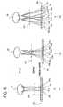
- FIG. 7illustrates a P3 type of display, again having pixel colours arranged as repeating RGB columns. When viewed from the middle of a viewing window, there are no undesirable colour artifacts and the red, green and blue pixel colours are visible in the correct ratios through each slit of the barrier 25 .
- FIG. 8illustrates what happens when adjacent groups of pixels for left and right images display different image data.
- each set of three pixel columns such as 36 for the left eye imageis shown displaying white whereas the pixel columns such as 37 displaying the right eye image are shown as being black.
- the displayis viewed from the centre of each viewing window as illustrated at 38 , there are no undesirable visual artifacts.
- FIG. 8illustrates at 39 the effect of a viewer moving to the left as compared with the situation illustrated at 38 .
- Thisis equivalent to a relative movement to the right of the barrier 25 .
- the effect of thisis that each red column of pixels of the left eye view becomes increasingly obscured.
- the red pixels of the right eye viewbecome visible, because they are black, the effect is that there is a colour shift towards cyan in the left eye view as perceived by the viewer.
- colour artifacts which are dependent on the image being displayedare perceived by the viewer when viewing the display from other than the optimal position.
- GB2399653discloses a non-periodic parallax barrier structure in which groups of evenly spaced slits are themselves evenly spaced apart with a different horizontal pitch. Vertically striped colour filtering is also disclosed.
- WO02091348discloses a single view or two-dimensional (2D) display having a non-standard pattern of pixel colouring.
- DE19822342discloses a multiple view display of the P3 type. In order to allow for lateral movement of an observer without shifting a parallax barrier structure relative to a pixel structure, columns of pixels additional to those viewable through each slit when the display is viewed correctly are switched.
- EP 1 427 223 and EP 0 829 743discloses P1 displays with repeating groups of RGB columns.
- EP 1 401 216, EPO 0 860 728, US 2002/0001128 and EP 0 847 208discloses viewer position indications in P1 displays.
- a multiple view displaycomprising: a parallax optic comprising a plurality of parallax elements spaced apart at a single first pitch; and a spatial light modulator comprising a plurality of columns of pixels arranged with a second pitch providing viewpoint correction for creating n primary viewing windows for viewing n views, where n is an integer greater than one, with w columns of pixels being viewable through each parallax element in each viewing window, where w is an integer greater than one, the pixels of each column being of a same colour, the columns being of x different colours, where x is an integer greater than two, and being arranged as a sequence of colours comprising repeating groups of a same sub-sequence, characterised in that each group comprises y subgroups of z columns, where y is an integer greater than one and z is an integer greater than or equal to x, each subgroup containing columns of all x colours, the smallest repetition pitch of the sequence being equal to y.z
- the modulatormay include a striped colour filter arrangement whose stripes are aligned with the columns.
- the number x of coloursmay be equal to three.
- the three coloursmay be primary colours.
- the primary coloursmay be red, green and blue.
- the number z of columns of each subgroupmay be equal to x.
- the number w of columns viewable in each windowmay be equal to two.
- the number y of subgroups in each groupmay be equal to three.
- Each sub-sequencemay be red, green, blue, green, blue, red, blue, red, green.
- the number w of columns viewable in each windowmay be equal to three.
- the number y of subgroups in each groupmay be equal to six.
- Each sub-sequencemay be red, green, blue, red, green, blue, green, blue, red, green, blue, red, blue, red, green, blue, red, green.
- a multiple view displaycomprising: a parallax optic comprising a plurality of parallax elements; and a spatial light modulator comprising a plurality of pixels arranged as rows and columns cooperating with the parallax optic to create n primary viewpoint-corrected viewing windows for viewing n views, where n is an integer greater than one, with a respective single column of pixels being viewable through each parallax element in each viewing window, the pixels being arranged as composite colour groups for displaying respective colour image elements, each group comprising z pixels of x different colours disposed adjacent each other in the same column, where x is an integer greater than two and z is an integer greater than or equal to x, the pixels of each colour for each view being disposed so as to be substantially evenly spaced horizontally and substantially evenly spaced vertically, characterised in that the order in the column direction of the colours of the pixels of each group is different from the order in the column direction of the colours of the pixels of each adjacent group in the same rows
- the pixels of each colourmay be disposed so as to be substantially evenly spaced horizontally and substantially evenly spaced vertically on the modulator.
- the pixelsmay be arranged in the row direction as repeating sets of z pixels of the x different colours with each row being offset in the row direction relative to each adjacent row by a number of pixels greater than zero and less than z.
- the offsets between adjacent rowsmay have the same magnitudes.
- the offsets between adjacent rowsmay have the same directions.
- the number x of different coloursmay be three.
- the three coloursmay be primary colours.
- the primary coloursmay be red, green and blue.
- the number z of pixels in each groupmay be equal to x.
- a multiple view displaycomprising: a parallax optic comprising a plurality of parallax elements; and a spatial light modulator comprising a plurality of pixels arranged as rows and columns cooperating with the parallax optic to create n primary viewpoint-corrected viewing windows for viewing n views, where n is an integer greater than one, with w pixels in each row being viewable through each parallax element in each viewing window, where w is an integer greater than one, characterised in that the rows are arranged as groups and the parallax elements are arranged as rows, each of which is aligned with a respective group of rows of pixels, the pixels comprising sets of pixels of different colours arranged such that the sequence of pixel colours viewable in each viewing window through each parallax element of each row of parallax elements is different from the sequence of pixel colours viewable through the or each nearest parallax element in the or each adjacent row of parallax elements.
- the parallax elementsmay be aligned in the row direction.
- the parallax elementsmay be continuous in the column direction.
- the pixelsmay be arranged as repeating colour sequences in the row direction and the rows of pixels of each adjacent pair of groups may be offset with respect to each other in the row direction by at least one pixel pitch and by less than the smallest repetition pitch of the repeating colour sequence.
- the pixels of each colourmay be arranged as columns.
- the parallax elements of each adjacent pair of rowsmay be offset with respect to each other in the row direction.
- the offsetsmay be of the same magnitude.
- the offsetsmay be in the same direction.
- the groups of rows of pixels or the rows of parallax elementsmay be arranged as sets with offsets of the sets being in the same direction and with the offsets of adjacent pairs of sets being in opposite directions.
- Each group of rowsmay comprise a single row.
- Each group of rowsmay comprise a plurality of rows.
- Each group of rowsmay comprise n rows, the display may be rotatable between a portrait orientation and a landscape orientation, and the parallax elements may be arranged to provide two dimensional parallax.
- the offsetmay differ from twice the pitch of the columns to provide viewpoint correction.
- the pixels of each rowmay be arranged as groups of n.w pixels separated from each other by the pitch of the columns.
- the number wmay be equal to two and the different sequences of pixel colours may comprise different combinations.
- the number wmay be equal to three and the different sequences of pixel colours may comprise different per-mutations.
- the parallax opticmay be a parallax barrier.
- the spatial light modulatormay be a light-attenuating modulator.
- the modulatormay be transmissive.
- the modulatormay be a liquid crystal device.
- the number n of windowsmay be equal to two.
- the sets of pixelsmay be of three colours.
- the three coloursmay be primary colours.
- the primary coloursmay be red, green and blue.
- Embodiments and examples of such a displaymay achieve combinations of one or more of the following advantages:
- Pn displayswhere n is greater than one provide an advantage in that the space in between a pixel plane of the spatial light modulator and a plane containing the parallax elements may be made greater than for P1 displays.
- any substrate between the planescan be of larger thickness and this reduces manufacturing problems, for example in handling relatively thin glass.
- the parallax opticsuch as a parallax barrier
- itmakes it possible or easier for the parallax optic, such as a parallax barrier, to be of an active type without requiring the use of thin substrates such as thin glass. It is therefore easier to provide a display which is switchable between multiple view and single view modes.
- a parallax barriercan be embodied by a liquid crystal device which can be switched to a substantially uniform transmissive mode so as effectively to disable the parallax barrier and permit normal viewing of a single image or view throughout a wide viewing region.
- FIG. 1is a diagrammatic horizontal cross-sectional view of a known multiple view display
- FIGS. 2 and 3are diagrammatic plan views illustrating the generation of viewing regions and the effect of viewpoint correction
- FIG. 4is a diagrammatic horizontal cross-sectional view of another known multiple view display
- FIG. 5is a diagrammatic plan view illustrating different types of known multiple view displays
- FIG. 6illustrates an undesirable colour artifact produced by a known type of P2 display
- FIGS. 7 and 8illustrate the generation of an undesirable visual artifact in a known type of P3 display
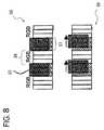
- FIG. 9is a diagram illustrating a multiple view P2 display constituting an embodiment of the invention.
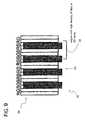
- FIG. 10is a diagram illustrating a multiple view P3 display constituting an embodiment of the invention.
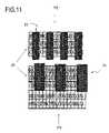
- FIG. 11is a diagram illustrating P2 and P3 displays constituting embodiments of the invention.
- FIG. 12illustrates another pixel arrangement for use in an embodiment of the invention
- FIG. 13is a diagram illustrating a known P1 type of display and a P1 type of display constituting an embodiment of the invention
- FIGS. 14 to 16illustrate further pixel arrangements for displays constituting embodiments of the invention
- FIGS. 17 and 18illustrate P2 types of displays with staggered barrier slit arrangements constituting embodiments of the invention
- FIG. 19illustrates a P3 type of display with a staggered barrier slit arrangement constituting an embodiment of the invention
- FIG. 20illustrates a display of the type shown in FIG. 19 with a zig-zag barrier slit arrangement
- FIG. 21illustrates a display of the type shown in FIG. 17 with a zig-zag barrier slit arrangement
- FIG. 22illustrates a P3 type of display having portrait and landscape viewing modes and constituting an embodiment of the invention.
- FIG. 23illustrates another P3 type of display having portrait and landscape viewing modes and constituting an embodiment of the invention.
- the multiple view displays described hereinafterare all of the two or dual view type but displays providing more than two views may also be provided.
- the displaysmay be used for any suitable application such as autostereoscopic 3D image display and display to more than one viewer of images which may be independent and unrelated to each other.
- All of the displaysare colour displays made up of red, green and blue pixels with triplets of RGB pixels forming a composite colour or “white” group.
- other arrangementsare possible, such as composite groups comprising RGGB pixels or RGYB pixels, where Y pixels are white.
- the displayscomprise flat panel liquid crystal devices as the spatial light modulators and parallax barriers as the parallax optics.
- other types of spatial light modulators (including light-emitting types) and other types of parallax opticsmay be used.
- the P2 display shown in FIG. 9comprises and LCD and a parallax barrier 25 such that two columns of pixels with associated colour filter stripes are viewable in each viewing region through each slit of the parallax barrier 25 .
- the displaydiffers from known types of display in the horizontal ordering or sequence of red, green and blue filter stripes which extend vertically in the column direction of pixels and each of which is associated with a single pixel column.
- the filter sequence(from left to right in FIG. 9 ) comprises a repeating subsequence of RGBGBRBRG filter stripes.
- Such an arrangementreduces undesirable colour artifacts in multiple view image displays.
- undesirable colour stripeswith a period of nine pixel column may be generated.
- a region with a relatively high density of blue pixelsis illustrated at 40 .
- FIG. 10illustrates a P3 display in which the pixel colour sequence in the horizontal or row direction differs from known displays.
- the pixel coloursare arranged as a repeating sequence of RGBRGBGBRGBRBRGBRG.
- FIG. 11illustrates alternative P2 and P3 displays in which the pixels are not arranged as columns of single colours.
- each rowcomprises a repeating sequence of RGB pixels.
- the patterns in adjacent rowsare staggered or offset in the row direction by one pixel so that the pixels of each colour are aligned diagonally on the LCD 20 .
- the colours“average” vertically through the barrier slits so that undesirable colour artifacts are substantially avoided in the multiple view and single view modes.
- different colour shiftsoccur in different rows, so that undesirable colour shift artifacts are substantially avoided.
- FIG. 12illustrates an alternative pixel colour pattern for a P2 or P3 display differing from those illustrated in FIG. 11 in that the rows are staggered or offset in one direction for three rows and then in the opposite direction for three rows. Such an arrangement may be used to remove or reduce any undesirable effects caused by the diagonal colour striping in FIG. 11 , for example in the single view mode.
- Adjacent rowsmay be offset by one or two pixel pitches in the case of LCDs having pixels of three different colours.
- the order of the pixel coloursmay be changed in each row.
- FIG. 13illustrates a P1 display of known type at 41 and a P1 display constituting an embodiment of the invention at 42 .
- the P1 display at 42uses the same colour pixel pattern as the displays shown in FIG. 11 so that the pixels of each colour which are viewable in each viewing window are substantially evenly spaced vertically and horizontally, although the vertical and horizontal pitches may be different from each other.
- P2 and P3 displaysare used as autostereoscopic 3D displays
- a binocular disparitymay arise between pixels of different colours because of the colour pixel patterning in relation to the parallax barrier structure. This may result in unexpected stereoscopic features.
- a red plane and a green planewhich are intended to appear at the same distance from the viewer may appear to be separated in depth.
- FIGS. 14 to 16illustrate colour pixel patterns which may be used in order to reduce variations in binocular disparity between the individual colours.
- FIGS. 14 and 15illustrate patterns for use with displays of the P2 type.
- FIG. 14illustrates a pattern in which the colours are arranged as vertical strips with a horizontally repeating sequence of RGRGBRBRGBGB.
- FIG. 15illustrates a pattern based on the same repeating colour sequence but in which adjacent rows are offset by four pixel column widths.
- the pattern shown in FIG. 16is the same as that shown in FIG. 9 .
- each parallax barrier 25comprises evenly spaced continuous vertical slits.
- adjacent rows of pixel coloursare offset from each other in the row direction.
- the continuous vertical slitsare equivalent to and may be considered as individual slits for each row, which slits are aligned with each other in the row direction to form the continuous vertical slits in the column direction.
- a similar performancemay be achieved by having offset rows of slits cooperating with colour pixel patterns where each column of pixels is of the same colour.
- FIG. 17illustrates an example of such an arrangement in which the colour filter stripes are arranged as a repeating sequence of RGB stripes.
- Each row of pixelscooperates with a row of slits with the slits of adjacent rows being offset approximately by the pixel column pitch (allowing for view point compensation).
- This arrangementmay be used in a P2 type of display and is effectively equivalent to the P2 display shown in FIG. 11 .
- FIG. 18illustrates a P2 display in which the offset between adjacent rows of slits of the parallax barrier is equal to approximately twice the pixel column pitch (allowing for viewpoint compensation).
- FIG. 19illustrates a P3 display in which the adjacent rows of slits are offset relative to each other by approximately one pixel column pitch (allowing for viewpoint compensation).
- Displays of the type shown in FIGS. 17 to 19have limited vertical freedom of movement of the viewer in order to avoid crosstalk.
- the wrong pixelsbecome visible through the parallax barrier slits. This effect may be reduced by reducing the height of the individual slits (indicated by X in FIG. 19 ) to provide greater vertical viewing freedom at the expense of reduced brightness for a given display illumination.
- FIGS. 20 and 21illustrate modifications of the P3 and P2 displays shown in FIGS. 19 and 17 , respectively, in order to reduce or remove any diagonal “banding” which might be unacceptable.
- the parallax barrier slit rowsare offset in one direction for three rows and then in the opposite direction for three rows.
- FIG. 22illustrates a P3 display which may be used in a portrait viewing mode or a landscape viewing mode or may be switched between these modes.
- the LCD 20comprises a vertically striped colour filter with repeating groups of RGB stripes, for example as illustrated in FIG. 7 .
- the individual colour pixelsare arranged as square-shaped composite colour groups so that the pitch p 2 of the rows is approximately three times the pitch p 1 of the columns with the display oriented in the portrait mode.
- the parallax barriercomprises a pattern of openings such as 50 of square shape.
- the openings 50are arranged as rows with a pitch differing from 6p1 so as to provide viewpoint correction. Adjacent rows are offset with respect to each other by approximately the column pitch p 1 and each row of openings 50 cooperates with two rows of pixels.
- pixels of different coloursare indicated by different shading and the pixels which display left and right image pixels are indicated by L and R, respectively.
- the display of FIG. 22overcomes the colour shifting artifacts described hereinbefore in the same way as the display illustrated in FIG. 19 .
- the displayIn the landscape mode, the display is effectively rotated through 90 degrees so that the barrier openings 50 are arranged as columns with a pitch of 2p2.
- the right and left eyes of the viewer 30can see the same areas of pixels of different colours throughout a wide lateral viewing range without any undesirable colour shifting artifacts.
- the allocation of the LCD pixels to the left and right imageschanges between the portrait and landscape modes.
- a display controllermay be arranged to allocate the pixels correctly to the left and right views when the display orientation is changed. This may be actuated automatically or manually.
- the display controllermay be preset to provide the pixel allocation for the mode of operation of the display.
- FIG. 23illustrates only the portrait mode of another P3 display which may be switched between portrait and landscape modes.
- the rows of pixelare arranged in groups of six separated from each other by pixels such as 51 which are switched to their black state.
- pixels 51may be used to display data for one of the views or may be controlled to show a grey level appropriate to both views so as to increase viewer freedom.
- the rows of openingsare staggered in the row direction by an amount which differs from twice the column pitch in order to provide viewpoint correction.
- the pixels 51 which are switched to blackare staggered in adjacent rows by twice the column pitch.
- the parallax barrier in all of the embodimentsmay be removed or disabled.
- the parallax barriermay comprise a switchable liquid crystal cell having the appropriate electrode-patterning so as to be switchable between a multiple view mode with the barrier structure being provided and a single view mode with the barrier structure being disabled.
Landscapes
- Engineering & Computer Science (AREA)
- Physics & Mathematics (AREA)
- Multimedia (AREA)
- Signal Processing (AREA)
- General Physics & Mathematics (AREA)
- Optics & Photonics (AREA)
- Marketing (AREA)
- Accounting & Taxation (AREA)
- Theoretical Computer Science (AREA)
- Business, Economics & Management (AREA)
- Liquid Crystal (AREA)
- Testing, Inspecting, Measuring Of Stereoscopic Televisions And Televisions (AREA)
- Transforming Electric Information Into Light Information (AREA)
- Video Image Reproduction Devices For Color Tv Systems (AREA)
- Liquid Crystal Display Device Control (AREA)
Abstract
Description
Claims (45)
Applications Claiming Priority (3)
| Application Number | Priority Date | Filing Date | Title |
|---|---|---|---|
| GB0420945.8 | 2004-09-21 | ||
| GB0420945AGB2418315A (en) | 2004-09-21 | 2004-09-21 | Multiple view display |
| PCT/JP2005/017670WO2006033447A2 (en) | 2004-09-21 | 2005-09-20 | Multiple view display |
Publications (2)
| Publication Number | Publication Date |
|---|---|
| US20080043092A1 US20080043092A1 (en) | 2008-02-21 |
| US8149272B2true US8149272B2 (en) | 2012-04-03 |
Family
ID=33306937
Family Applications (1)
| Application Number | Title | Priority Date | Filing Date |
|---|---|---|---|
| US11/575,599Expired - Fee RelatedUS8149272B2 (en) | 2004-09-21 | 2005-09-20 | Multiple view display |
Country Status (6)
| Country | Link |
|---|---|
| US (1) | US8149272B2 (en) |
| JP (2) | JP4968943B2 (en) |
| KR (2) | KR100900613B1 (en) |
| CN (2) | CN102202223B (en) |
| GB (1) | GB2418315A (en) |
| WO (1) | WO2006033447A2 (en) |
Cited By (13)
| Publication number | Priority date | Publication date | Assignee | Title |
|---|---|---|---|---|
| US20110170607A1 (en)* | 2010-01-11 | 2011-07-14 | Ubiquity Holdings | WEAV Video Compression System |
| US20110242298A1 (en)* | 2009-08-21 | 2011-10-06 | Microsoft Corporation | Private video presentation |
| US20130181968A1 (en)* | 2010-09-21 | 2013-07-18 | Sharp Kabushiki Kaisha | Drive circuit of display device, display device, and method of driving display device |
| US20130241905A1 (en)* | 2012-03-16 | 2013-09-19 | Samsung Display Co., Ltd. | Stereoscopic display device |
| US8740693B2 (en) | 2007-02-02 | 2014-06-03 | Wms Gaming Inc. | Gaming systems having multi-output displays |
| US9201185B2 (en) | 2011-02-04 | 2015-12-01 | Microsoft Technology Licensing, Llc | Directional backlighting for display panels |
| US9256089B2 (en) | 2012-06-15 | 2016-02-09 | Microsoft Technology Licensing, Llc | Object-detecting backlight unit |
| US9268373B2 (en) | 2012-03-02 | 2016-02-23 | Microsoft Technology Licensing, Llc | Flexible hinge spine |
| US9304949B2 (en) | 2012-03-02 | 2016-04-05 | Microsoft Technology Licensing, Llc | Sensing user input at display area edge |
| US9354748B2 (en) | 2012-02-13 | 2016-05-31 | Microsoft Technology Licensing, Llc | Optical stylus interaction |
| US9870066B2 (en) | 2012-03-02 | 2018-01-16 | Microsoft Technology Licensing, Llc | Method of manufacturing an input device |
| US10678743B2 (en) | 2012-05-14 | 2020-06-09 | Microsoft Technology Licensing, Llc | System and method for accessory device architecture that passes via intermediate processor a descriptor when processing in a low power state |
| US12164119B2 (en) | 2018-11-05 | 2024-12-10 | Leia Inc. | Multiview display and method |
Families Citing this family (84)
| Publication number | Priority date | Publication date | Assignee | Title |
|---|---|---|---|---|
| JP4617924B2 (en)* | 2005-02-25 | 2011-01-26 | カシオ計算機株式会社 | Liquid crystal display device |
| KR100753517B1 (en)* | 2005-10-12 | 2007-08-31 | 엘지전자 주식회사 | A mobile communication terminal having a stereoscopic image display function and a stereoscopic image display method using the same |
| KR100922754B1 (en)* | 2006-09-12 | 2009-10-21 | 삼성모바일디스플레이주식회사 | Dual screen display panel |
| GB0716776D0 (en)* | 2007-08-29 | 2007-10-10 | Setred As | Rendering improvement for 3D display |
| KR101339768B1 (en)* | 2007-08-30 | 2013-12-11 | 삼성전자주식회사 | Plane light source and lcd backlight unit comprising the same |
| KR101411738B1 (en)* | 2007-11-07 | 2014-06-26 | 엘지디스플레이 주식회사 | Image display device |
| JP2009134068A (en)* | 2007-11-30 | 2009-06-18 | Seiko Epson Corp | Display device, electronic device, and image processing method |
| KR101294234B1 (en)* | 2007-12-04 | 2013-08-16 | 엘지디스플레이 주식회사 | 3D image display device |
| DE102008060279B4 (en) | 2007-12-05 | 2023-09-14 | Lg Display Co., Ltd. | Multi-view display device |
| US9794547B2 (en)* | 2008-02-11 | 2017-10-17 | Koninklijke Philips N.V. | Autostereoscopic image output device |
| CN101364364B (en)* | 2008-07-10 | 2014-11-26 | 湖南创图视维科技有限公司 | LED large scale freedom stereo display technique |
| JP2010066511A (en)* | 2008-09-10 | 2010-03-25 | Pavonine Korea Inc | 3d-display device of non-eyeglass system |
| GB2464521A (en)* | 2008-10-20 | 2010-04-21 | Sharp Kk | Processing image data for multiple view displays |
| DE102009009443B3 (en)* | 2009-02-14 | 2010-09-23 | Fraunhofer-Gesellschaft zur Förderung der angewandten Forschung e.V. | Monitor and method for displaying autostereoscopic images |
| JP5381423B2 (en)* | 2009-07-06 | 2014-01-08 | セイコーエプソン株式会社 | Electro-optical device and electronic apparatus |
| JP5667752B2 (en)* | 2009-08-20 | 2015-02-12 | 株式会社ジャパンディスプレイ | 3D image display device |
| JP5462672B2 (en)* | 2010-03-16 | 2014-04-02 | 株式会社ジャパンディスプレイ | Display device and electronic device |
| TW201133032A (en)* | 2010-03-23 | 2011-10-01 | Unique Instr Co Ltd | Multi-function LCD parallax grating device |
| KR101174076B1 (en)* | 2010-08-31 | 2012-08-16 | 유한회사 마스터이미지쓰리디아시아 | Auto stereoscopic Display Apparatus Using Diagonal Direction Parallax Barrier |
| JP2012108316A (en)* | 2010-11-17 | 2012-06-07 | Sony Corp | Stereoscopic display device |
| JP5321575B2 (en)* | 2010-12-17 | 2013-10-23 | 株式会社Jvcケンウッド | Autostereoscopic display device |
| JP2012141400A (en)* | 2010-12-28 | 2012-07-26 | Sony Corp | Driving method of stereoscopic display device, and stereoscopic display device |
| JP2012155307A (en)* | 2011-01-05 | 2012-08-16 | Sony Mobile Display Corp | Display device |
| TWI569041B (en) | 2011-02-14 | 2017-02-01 | 半導體能源研究所股份有限公司 | Display device |
| US9443455B2 (en) | 2011-02-25 | 2016-09-13 | Semiconductor Energy Laboratory Co., Ltd. | Display device having a plurality of pixels |
| US9558687B2 (en) | 2011-03-11 | 2017-01-31 | Semiconductor Energy Laboratory Co., Ltd. | Display device and method for driving the same |
| JP6147953B2 (en)* | 2011-03-15 | 2017-06-14 | 株式会社ジャパンディスプレイ | Display device |
| TWI420152B (en)* | 2011-04-26 | 2013-12-21 | Unique Instr Co Ltd | A Method of Multi - view Three - dimensional Image Display |
| JP5628088B2 (en) | 2011-04-28 | 2014-11-19 | 株式会社ジャパンディスプレイ | Display panel, display device and electronic device |
| JP2013088685A (en) | 2011-10-20 | 2013-05-13 | Japan Display West Co Ltd | Display device |
| US9055289B2 (en)* | 2011-11-23 | 2015-06-09 | Korea Institute Of Science And Technology | 3D display system |
| JP5779124B2 (en)* | 2012-03-13 | 2015-09-16 | 株式会社ジャパンディスプレイ | Display device and electronic device |
| US9678267B2 (en) | 2012-05-18 | 2017-06-13 | Reald Spark, Llc | Wide angle imaging directional backlights |
| US9188731B2 (en) | 2012-05-18 | 2015-11-17 | Reald Inc. | Directional backlight |
| EP2850488A4 (en) | 2012-05-18 | 2016-03-02 | Reald Inc | Directional backlight |
| US9235057B2 (en) | 2012-05-18 | 2016-01-12 | Reald Inc. | Polarization recovery in a directional display device |
| KR102099590B1 (en) | 2012-05-18 | 2020-04-10 | 리얼디 스파크, 엘엘씨 | Controlling light sources of a directional backlight |
| JP6099892B2 (en)* | 2012-07-09 | 2017-03-22 | パナソニック インテレクチュアル プロパティ コーポレーション オブ アメリカPanasonic Intellectual Property Corporation of America | Video display device |
| WO2014018269A1 (en)* | 2012-07-23 | 2014-01-30 | Reald Inc. | Observer tracking autostereoscopic display |
| FR2994044B1 (en) | 2012-07-24 | 2017-05-12 | Alioscopy | SELESTHETICALLY DISPLAYED METHOD ON A SCREEN HAVING ITS GREATEST DIMENSION IN THE VERTICAL DIRECTION. |
| US9420266B2 (en) | 2012-10-02 | 2016-08-16 | Reald Inc. | Stepped waveguide autostereoscopic display apparatus with a reflective directional element |
| KR102008323B1 (en)* | 2012-12-14 | 2019-10-22 | 엘지디스플레이 주식회사 | Three Dimensional Image Display Device |
| EP2936807A4 (en)* | 2012-12-24 | 2016-06-08 | Thomson Licensing | DISPLAY UNIT FOR ROTATING DISPLAY OF AN AUTOSTEREOSCOPIC PRESENTATION |
| CN111487707A (en) | 2013-02-22 | 2020-08-04 | 瑞尔D斯帕克有限责任公司 | directional backlight |
| JP5942129B2 (en)* | 2013-03-14 | 2016-06-29 | 株式会社ジャパンディスプレイ | Display device |
| KR102254799B1 (en) | 2013-06-17 | 2021-05-24 | 리얼디 스파크, 엘엘씨 | Controlling light sources of a directional backlight |
| KR101505962B1 (en)* | 2013-09-30 | 2015-03-26 | (주) 스카이미디어 | Digital information dispaly for simultaneous implementation of 2D and 3D image |
| EP3058562A4 (en) | 2013-10-14 | 2017-07-26 | RealD Spark, LLC | Control of directional display |
| KR102366346B1 (en) | 2013-10-14 | 2022-02-23 | 리얼디 스파크, 엘엘씨 | Light input for directional backlight |
| KR102171611B1 (en)* | 2013-12-31 | 2020-10-30 | 엘지디스플레이 주식회사 | Stereopsis image display device |
| CN103792607B (en)* | 2014-01-26 | 2016-02-24 | 京东方科技集团股份有限公司 | Grating and display device |
| WO2015145934A1 (en)* | 2014-03-27 | 2015-10-01 | パナソニックIpマネジメント株式会社 | Virtual-image display apparatus, heads-up-display system, and vehicle |
| GB2527549A (en)* | 2014-06-25 | 2015-12-30 | Sharp Kk | Image data redundancy for high quality 3D |
| EP3161550A4 (en) | 2014-06-26 | 2018-04-18 | RealD Spark, LLC | Directional privacy display |
| WO2016057690A1 (en) | 2014-10-08 | 2016-04-14 | Reald Inc. | Directional backlight |
| US10356383B2 (en) | 2014-12-24 | 2019-07-16 | Reald Spark, Llc | Adjustment of perceived roundness in stereoscopic image of a head |
| RU2596062C1 (en) | 2015-03-20 | 2016-08-27 | Автономная Некоммерческая Образовательная Организация Высшего Профессионального Образования "Сколковский Институт Науки И Технологий" | Method for correction of eye image using machine learning and method of machine learning |
| WO2016168345A1 (en) | 2015-04-13 | 2016-10-20 | Reald Inc. | Wide angle imaging directional backlights |
| CN107850804B (en) | 2015-05-27 | 2021-06-11 | 瑞尔D斯帕克有限责任公司 | Wide-angle imaging directional backlight |
| US10475418B2 (en) | 2015-10-26 | 2019-11-12 | Reald Spark, Llc | Intelligent privacy system, apparatus, and method thereof |
| WO2017083526A1 (en) | 2015-11-10 | 2017-05-18 | Reald Inc. | Distortion matching polarization conversion systems and methods thereof |
| WO2017083583A1 (en) | 2015-11-13 | 2017-05-18 | Reald Spark, Llc | Surface features for imaging directional backlights |
| EP3374692B1 (en) | 2015-11-13 | 2021-02-24 | RealD Spark, LLC | Wide angle imaging directional backlights |
| KR102463171B1 (en) | 2015-12-24 | 2022-11-04 | 삼성전자주식회사 | Optical layer and desplay device including the same |
| CN114143495B (en) | 2016-01-05 | 2025-07-15 | 瑞尔D斯帕克有限责任公司 | Gaze Correction for Multi-View Images |
| DE102016202431A1 (en)* | 2016-02-17 | 2017-08-31 | Fraunhofer-Gesellschaft zur Förderung der angewandten Forschung e.V. | Autostereoscopic screen and its use for reproducing three-dimensionally perceptible images |
| EP3458897B1 (en) | 2016-05-19 | 2025-04-02 | RealD Spark, LLC | Wide angle imaging directional backlights |
| US10425635B2 (en) | 2016-05-23 | 2019-09-24 | Reald Spark, Llc | Wide angle imaging directional backlights |
| CN106297642B (en)* | 2016-10-28 | 2017-09-15 | 京东方科技集团股份有限公司 | Display panel, display module and its driving method, drive device, display device |
| WO2018092877A1 (en)* | 2016-11-17 | 2018-05-24 | 凸版印刷株式会社 | Reflective display apparatus |
| WO2018129059A1 (en) | 2017-01-04 | 2018-07-12 | Reald Spark, Llc | Optical stack for imaging directional backlights |
| US10244230B2 (en)* | 2017-03-01 | 2019-03-26 | Avalon Holographics Inc. | Directional pixel for multiple view display |
| EP3607387A4 (en) | 2017-04-03 | 2020-11-25 | RealD Spark, LLC | Segmented imaging directional backlights |
| CN111183405A (en) | 2017-08-08 | 2020-05-19 | 瑞尔D斯帕克有限责任公司 | Adjust the digital representation of the head area |
| WO2019090246A1 (en) | 2017-11-06 | 2019-05-09 | Reald Spark, Llc | Privacy display apparatus |
| KR102759510B1 (en) | 2018-01-25 | 2025-02-04 | 리얼디 스파크, 엘엘씨 | Touchscreen for privacy display |
| CN108469682A (en)* | 2018-03-30 | 2018-08-31 | 京东方科技集团股份有限公司 | A kind of three-dimensional display apparatus and its 3 D displaying method |
| JP7227448B2 (en)* | 2018-07-18 | 2023-02-22 | 日本電信電話株式会社 | Display device and display method |
| CN109409474A (en)* | 2018-09-28 | 2019-03-01 | 明基智能科技(上海)有限公司 | Coding method |
| EP3963382A4 (en)* | 2019-04-29 | 2022-12-14 | LEIA Inc. | DISPLAY WITH MULTIPLE VIEWS AND METHODS WITH SHIFTED COLOR SUB-PIXELS |
| US20210191191A1 (en)* | 2019-12-18 | 2021-06-24 | Innolux Corporation | Electronic device |
| CN116194812A (en) | 2020-09-16 | 2023-05-30 | 瑞尔D斯帕克有限责任公司 | Vehicle Exterior Lighting |
| US11966049B2 (en) | 2022-08-02 | 2024-04-23 | Reald Spark, Llc | Pupil tracking near-eye display |
| WO2024035796A1 (en) | 2022-08-11 | 2024-02-15 | Reald Spark, Llc | Anamorphic directional illumination device |
Citations (11)
| Publication number | Priority date | Publication date | Assignee | Title |
|---|---|---|---|---|
| US5991073A (en)* | 1996-01-26 | 1999-11-23 | Sharp Kabushiki Kaisha | Autostereoscopic display including a viewing window that may receive black view data |
| US6055013A (en)* | 1997-02-04 | 2000-04-25 | Sharp Kabushiki Kaisha | Autostereoscopic display |
| EP1067805A2 (en) | 1999-07-07 | 2001-01-10 | Sharp Kabushiki Kaisha | Stereoscopic display |
| US6611243B1 (en)* | 1998-05-12 | 2003-08-26 | Sharp Kabushiki Kaisha | Directional display |
| US20040057016A1 (en)* | 2002-09-17 | 2004-03-25 | Jones Graham Roger | Autostereoscopic display |
| EP1427223A2 (en) | 2002-12-07 | 2004-06-09 | Sharp Kabushiki Kaisha | Multiple view display |
| GB2399653A (en) | 2003-03-21 | 2004-09-22 | Sharp Kk | Parallax barrier for multiple view display |
| US20060152812A1 (en)* | 2003-07-10 | 2006-07-13 | Ocuity Limited | Lens array structure |
| US20060164528A1 (en)* | 2003-07-10 | 2006-07-27 | Jonathan Harrold | Pixel arrangement for an autostereoscopic display apparatus |
| US20060170616A1 (en) | 2002-07-08 | 2006-08-03 | Yuzo Hirayama | 3D image reproduction apparatus |
| US20070109400A1 (en)* | 2003-07-10 | 2007-05-17 | Ocuity Limited | Directional display apparatus |
Family Cites Families (6)
| Publication number | Priority date | Publication date | Assignee | Title |
|---|---|---|---|---|
| JP3459721B2 (en)* | 1995-05-22 | 2003-10-27 | キヤノン株式会社 | Stereoscopic image display method and stereoscopic image display device using the same |
| GB2320156A (en)* | 1996-12-07 | 1998-06-10 | Sharp Kk | Directional display and method of making a mask for a directional display |
| US6046849A (en)* | 1996-09-12 | 2000-04-04 | Sharp Kabushiki Kaisha | Parallax barrier, display, passive polarisation modulating optical element and method of making such an element |
| GB2317291A (en)* | 1996-09-12 | 1998-03-18 | Sharp Kk | Observer tracking directional display |
| JP2003029205A (en)* | 2001-07-13 | 2003-01-29 | Dainippon Printing Co Ltd | Color stereoscopic display |
| JP2006511844A (en)* | 2002-12-20 | 2006-04-06 | イクスドライデー テヒノロギーズ ゲーエムベーハー | Equipment for 2D or 3D display |
- 2004
- 2004-09-21GBGB0420945Apatent/GB2418315A/ennot_activeWithdrawn
- 2005
- 2005-09-20KRKR1020077008956Apatent/KR100900613B1/ennot_activeExpired - Fee Related
- 2005-09-20CNCN2011101112566Apatent/CN102202223B/ennot_activeExpired - Fee Related
- 2005-09-20JPJP2007506394Apatent/JP4968943B2/ennot_activeExpired - Lifetime
- 2005-09-20WOPCT/JP2005/017670patent/WO2006033447A2/enactiveApplication Filing
- 2005-09-20CNCN2005800363678Apatent/CN101049028B/ennot_activeExpired - Fee Related
- 2005-09-20USUS11/575,599patent/US8149272B2/ennot_activeExpired - Fee Related
- 2005-09-20KRKR1020097004179Apatent/KR100944304B1/ennot_activeExpired - Fee Related
- 2011
- 2011-03-07JPJP2011049697Apatent/JP5301591B2/ennot_activeExpired - Fee Related
Patent Citations (17)
| Publication number | Priority date | Publication date | Assignee | Title |
|---|---|---|---|---|
| US5991073A (en)* | 1996-01-26 | 1999-11-23 | Sharp Kabushiki Kaisha | Autostereoscopic display including a viewing window that may receive black view data |
| US6055013A (en)* | 1997-02-04 | 2000-04-25 | Sharp Kabushiki Kaisha | Autostereoscopic display |
| US6611243B1 (en)* | 1998-05-12 | 2003-08-26 | Sharp Kabushiki Kaisha | Directional display |
| EP1067805A2 (en) | 1999-07-07 | 2001-01-10 | Sharp Kabushiki Kaisha | Stereoscopic display |
| JP2001075049A (en) | 1999-07-07 | 2001-03-23 | Sharp Corp | 3D display |
| US6703989B1 (en)* | 1999-07-07 | 2004-03-09 | Sharp Kabushiki Kaisha | Stereoscopic display |
| US20060170616A1 (en) | 2002-07-08 | 2006-08-03 | Yuzo Hirayama | 3D image reproduction apparatus |
| US6929369B2 (en)* | 2002-09-17 | 2005-08-16 | Sharp Kabushiki Kaisha | Autostereoscopic display |
| US20040057016A1 (en)* | 2002-09-17 | 2004-03-25 | Jones Graham Roger | Autostereoscopic display |
| US20040119896A1 (en)* | 2002-12-07 | 2004-06-24 | Kean Diana U. | Multiple view display |
| JP2004206089A (en) | 2002-12-07 | 2004-07-22 | Sharp Corp | Multiple view display |
| EP1427223A2 (en) | 2002-12-07 | 2004-06-09 | Sharp Kabushiki Kaisha | Multiple view display |
| US7782409B2 (en)* | 2002-12-07 | 2010-08-24 | Sharp Kabushiki Kaisha | Multiple view display |
| GB2399653A (en) | 2003-03-21 | 2004-09-22 | Sharp Kk | Parallax barrier for multiple view display |
| US20060152812A1 (en)* | 2003-07-10 | 2006-07-13 | Ocuity Limited | Lens array structure |
| US20060164528A1 (en)* | 2003-07-10 | 2006-07-27 | Jonathan Harrold | Pixel arrangement for an autostereoscopic display apparatus |
| US20070109400A1 (en)* | 2003-07-10 | 2007-05-17 | Ocuity Limited | Directional display apparatus |
Non-Patent Citations (3)
| Title |
|---|
| International Search Report for corresponding Application No. PCT/JP2005/017670 mailed May 18, 2006. |
| Japanese Office Action for corresponding Japanese Application No. 2007-506394 dated Jan. 12, 2011. |
| Korean Office Action for corresponding application No. 10-2007-7008956 dated Nov. 27, 2008. |
Cited By (19)
| Publication number | Priority date | Publication date | Assignee | Title |
|---|---|---|---|---|
| US8740693B2 (en) | 2007-02-02 | 2014-06-03 | Wms Gaming Inc. | Gaming systems having multi-output displays |
| US20110242298A1 (en)* | 2009-08-21 | 2011-10-06 | Microsoft Corporation | Private video presentation |
| US20110170607A1 (en)* | 2010-01-11 | 2011-07-14 | Ubiquity Holdings | WEAV Video Compression System |
| US9106925B2 (en)* | 2010-01-11 | 2015-08-11 | Ubiquity Holdings, Inc. | WEAV video compression system |
| US20130181968A1 (en)* | 2010-09-21 | 2013-07-18 | Sharp Kabushiki Kaisha | Drive circuit of display device, display device, and method of driving display device |
| US9201185B2 (en) | 2011-02-04 | 2015-12-01 | Microsoft Technology Licensing, Llc | Directional backlighting for display panels |
| US9354748B2 (en) | 2012-02-13 | 2016-05-31 | Microsoft Technology Licensing, Llc | Optical stylus interaction |
| US9268373B2 (en) | 2012-03-02 | 2016-02-23 | Microsoft Technology Licensing, Llc | Flexible hinge spine |
| US9304949B2 (en) | 2012-03-02 | 2016-04-05 | Microsoft Technology Licensing, Llc | Sensing user input at display area edge |
| US9619071B2 (en) | 2012-03-02 | 2017-04-11 | Microsoft Technology Licensing, Llc | Computing device and an apparatus having sensors configured for measuring spatial information indicative of a position of the computing devices |
| US9678542B2 (en) | 2012-03-02 | 2017-06-13 | Microsoft Technology Licensing, Llc | Multiple position input device cover |
| US9870066B2 (en) | 2012-03-02 | 2018-01-16 | Microsoft Technology Licensing, Llc | Method of manufacturing an input device |
| US9904327B2 (en) | 2012-03-02 | 2018-02-27 | Microsoft Technology Licensing, Llc | Flexible hinge and removable attachment |
| US10013030B2 (en) | 2012-03-02 | 2018-07-03 | Microsoft Technology Licensing, Llc | Multiple position input device cover |
| US10963087B2 (en) | 2012-03-02 | 2021-03-30 | Microsoft Technology Licensing, Llc | Pressure sensitive keys |
| US20130241905A1 (en)* | 2012-03-16 | 2013-09-19 | Samsung Display Co., Ltd. | Stereoscopic display device |
| US10678743B2 (en) | 2012-05-14 | 2020-06-09 | Microsoft Technology Licensing, Llc | System and method for accessory device architecture that passes via intermediate processor a descriptor when processing in a low power state |
| US9256089B2 (en) | 2012-06-15 | 2016-02-09 | Microsoft Technology Licensing, Llc | Object-detecting backlight unit |
| US12164119B2 (en) | 2018-11-05 | 2024-12-10 | Leia Inc. | Multiview display and method |
Also Published As
| Publication number | Publication date |
|---|---|
| WO2006033447A2 (en) | 2006-03-30 |
| JP2008513807A (en) | 2008-05-01 |
| GB0420945D0 (en) | 2004-10-20 |
| GB2418315A (en) | 2006-03-22 |
| KR100900613B1 (en) | 2009-06-02 |
| KR20070068388A (en) | 2007-06-29 |
| CN102202223A (en) | 2011-09-28 |
| CN101049028B (en) | 2011-08-31 |
| CN101049028A (en) | 2007-10-03 |
| WO2006033447A3 (en) | 2006-07-13 |
| CN102202223B (en) | 2013-07-03 |
| KR20090037964A (en) | 2009-04-16 |
| US20080043092A1 (en) | 2008-02-21 |
| JP5301591B2 (en) | 2013-09-25 |
| JP2011158913A (en) | 2011-08-18 |
| KR100944304B1 (en) | 2010-02-24 |
| JP4968943B2 (en) | 2012-07-04 |
Similar Documents
| Publication | Publication Date | Title |
|---|---|---|
| US8149272B2 (en) | Multiple view display | |
| US7154653B2 (en) | Parallax barrier and multiple view display | |
| KR100577949B1 (en) | Multiple view display | |
| KR100627763B1 (en) | Multiple view display | |
| JP5576762B2 (en) | Display control device | |
| EP0791847B1 (en) | Autostereoscopic display apparatus | |
| JP2005086414A (en) | Stereoscopic display device and image display method | |
| GB2415850A (en) | Multiple view directional display operable in two orientations. | |
| JP2009139947A (en) | 3D image display apparatus and driving method thereof | |
| US20120113510A1 (en) | Display device and display method | |
| KR100429091B1 (en) | Autostereoscopic display apparatus | |
| GB2458340A (en) | Autostereoscopic display with improved viewing windows |
Legal Events
| Date | Code | Title | Description |
|---|---|---|---|
| AS | Assignment | Owner name:SHARP KABUSHIKI KAISHA, JAPAN Free format text:ASSIGNMENT OF ASSIGNORS INTEREST;ASSIGNORS:EVANS, ALLAN;MATHER, JONATHAN;JONES, GRAHAM;REEL/FRAME:019659/0379 Effective date:20070709 | |
| ZAAA | Notice of allowance and fees due | Free format text:ORIGINAL CODE: NOA | |
| ZAAB | Notice of allowance mailed | Free format text:ORIGINAL CODE: MN/=. | |
| STCF | Information on status: patent grant | Free format text:PATENTED CASE | |
| FEPP | Fee payment procedure | Free format text:PAYOR NUMBER ASSIGNED (ORIGINAL EVENT CODE: ASPN); ENTITY STATUS OF PATENT OWNER: LARGE ENTITY | |
| FPAY | Fee payment | Year of fee payment:4 | |
| MAFP | Maintenance fee payment | Free format text:PAYMENT OF MAINTENANCE FEE, 8TH YEAR, LARGE ENTITY (ORIGINAL EVENT CODE: M1552); ENTITY STATUS OF PATENT OWNER: LARGE ENTITY Year of fee payment:8 | |
| FEPP | Fee payment procedure | Free format text:MAINTENANCE FEE REMINDER MAILED (ORIGINAL EVENT CODE: REM.); ENTITY STATUS OF PATENT OWNER: LARGE ENTITY | |
| LAPS | Lapse for failure to pay maintenance fees | Free format text:PATENT EXPIRED FOR FAILURE TO PAY MAINTENANCE FEES (ORIGINAL EVENT CODE: EXP.); ENTITY STATUS OF PATENT OWNER: LARGE ENTITY | |
| STCH | Information on status: patent discontinuation | Free format text:PATENT EXPIRED DUE TO NONPAYMENT OF MAINTENANCE FEES UNDER 37 CFR 1.362 | |
| FP | Lapsed due to failure to pay maintenance fee | Effective date:20240403 |