US8148696B2 - Single-use external dosimeters for use in radiation therapies and related devices and computer program products - Google Patents
Single-use external dosimeters for use in radiation therapies and related devices and computer program productsDownload PDFInfo
- Publication number
- US8148696B2 US8148696B2US12/359,660US35966009AUS8148696B2US 8148696 B2US8148696 B2US 8148696B2US 35966009 AUS35966009 AUS 35966009AUS 8148696 B2US8148696 B2US 8148696B2
- Authority
- US
- United States
- Prior art keywords
- radiation
- reader
- sensor
- patch
- dose
- Prior art date
- Legal status (The legal status is an assumption and is not a legal conclusion. Google has not performed a legal analysis and makes no representation as to the accuracy of the status listed.)
- Expired - Fee Related
Links
- 238000004590computer programMethods0.000titleclaimsabstractdescription18
- 238000001959radiotherapyMethods0.000titledescription16
- 230000005855radiationEffects0.000claimsabstractdescription194
- 230000015654memoryEffects0.000claimsdescription88
- 238000012937correctionMethods0.000claimsdescription29
- 238000003860storageMethods0.000claimsdescription16
- 238000002560therapeutic procedureMethods0.000claimsdescription6
- 230000001225therapeutic effectEffects0.000claimsdescription5
- 238000011282treatmentMethods0.000abstractdescription71
- 230000001070adhesive effectEffects0.000abstractdescription32
- 239000000853adhesiveSubstances0.000abstractdescription31
- 238000000034methodMethods0.000abstractdescription27
- 238000012360testing methodMethods0.000description21
- 238000010586diagramMethods0.000description20
- 239000000463materialSubstances0.000description18
- 239000000758substrateSubstances0.000description16
- 206010028980NeoplasmDiseases0.000description15
- 238000005259measurementMethods0.000description15
- 230000008859changeEffects0.000description14
- 239000000523sampleSubstances0.000description14
- 206010073306Exposure to radiationDiseases0.000description12
- 238000004980dosimetryMethods0.000description12
- 238000012545processingMethods0.000description12
- 230000000875corresponding effectEffects0.000description11
- 230000005055memory storageEffects0.000description11
- 230000008569processEffects0.000description9
- 230000006870functionEffects0.000description8
- 238000006243chemical reactionMethods0.000description7
- RYGMFSIKBFXOCR-UHFFFAOYSA-NCopperChemical compound[Cu]RYGMFSIKBFXOCR-UHFFFAOYSA-N0.000description6
- 239000004793PolystyreneSubstances0.000description6
- 230000003287optical effectEffects0.000description6
- 229920002223polystyrenePolymers0.000description6
- 230000004044responseEffects0.000description6
- 230000035945sensitivityEffects0.000description6
- 238000011088calibration curveMethods0.000description5
- 238000004891communicationMethods0.000description5
- 230000000694effectsEffects0.000description5
- 238000007667floatingMethods0.000description5
- 238000012544monitoring processMethods0.000description5
- 239000004065semiconductorSubstances0.000description5
- 229910052802copperInorganic materials0.000description4
- 239000010949copperSubstances0.000description4
- 238000011065in-situ storageMethods0.000description4
- 238000012986modificationMethods0.000description4
- 230000004048modificationEffects0.000description4
- 238000012546transferMethods0.000description4
- 239000004593EpoxySubstances0.000description3
- LRUUNMYPIBZBQH-UHFFFAOYSA-NMethazoleChemical compoundO=C1N(C)C(=O)ON1C1=CC=C(Cl)C(Cl)=C1LRUUNMYPIBZBQH-UHFFFAOYSA-N0.000description3
- 239000011248coating agentSubstances0.000description3
- 238000000576coating methodMethods0.000description3
- 239000003086colorantSubstances0.000description3
- 238000004883computer applicationMethods0.000description3
- 230000001186cumulative effectEffects0.000description3
- 231100000673dose–response relationshipToxicity0.000description3
- 238000011156evaluationMethods0.000description3
- 238000003780insertionMethods0.000description3
- 230000037431insertionEffects0.000description3
- 238000004519manufacturing processMethods0.000description3
- 239000003973paintSubstances0.000description3
- 238000004088simulationMethods0.000description3
- 230000003068static effectEffects0.000description3
- 230000001954sterilising effectEffects0.000description3
- 238000004659sterilization and disinfectionMethods0.000description3
- 231100000987absorbed doseToxicity0.000description2
- 239000008280bloodSubstances0.000description2
- 210000004369bloodAnatomy0.000description2
- 238000004364calculation methodMethods0.000description2
- 238000012790confirmationMethods0.000description2
- 239000007799corkSubstances0.000description2
- 230000008878couplingEffects0.000description2
- 238000010168coupling processMethods0.000description2
- 238000005859coupling reactionMethods0.000description2
- 238000001514detection methodMethods0.000description2
- 239000002019doping agentSubstances0.000description2
- 238000005562fadingMethods0.000description2
- 230000005669field effectEffects0.000description2
- 239000000976inkSubstances0.000description2
- 239000012212insulatorSubstances0.000description2
- 230000005865ionizing radiationEffects0.000description2
- 150000002500ionsChemical class0.000description2
- 230000000670limiting effectEffects0.000description2
- 239000002184metalSubstances0.000description2
- 229910052751metalInorganic materials0.000description2
- 239000011253protective coatingSubstances0.000description2
- 230000001681protective effectEffects0.000description2
- 238000009718spray depositionMethods0.000description2
- 210000001685thyroid glandAnatomy0.000description2
- 238000012795verificationMethods0.000description2
- IAYPIBMASNFSPL-UHFFFAOYSA-NEthylene oxideChemical compoundC1CO1IAYPIBMASNFSPL-UHFFFAOYSA-N0.000description1
- WQZGKKKJIJFFOK-GASJEMHNSA-NGlucoseNatural productsOC[C@H]1OC(O)[C@H](O)[C@@H](O)[C@@H]1OWQZGKKKJIJFFOK-GASJEMHNSA-N0.000description1
- 230000004913activationEffects0.000description1
- 230000004888barrier functionEffects0.000description1
- 230000036760body temperatureEffects0.000description1
- 238000002725brachytherapyMethods0.000description1
- 210000004556brainAnatomy0.000description1
- 238000004422calculation algorithmMethods0.000description1
- 201000011510cancerDiseases0.000description1
- 238000012512characterization methodMethods0.000description1
- 230000003749cleanlinessEffects0.000description1
- 229920001577copolymerPolymers0.000description1
- 230000002596correlated effectEffects0.000description1
- 238000013500data storageMethods0.000description1
- 230000002950deficientEffects0.000description1
- 238000013461designMethods0.000description1
- 238000005516engineering processMethods0.000description1
- 125000003700epoxy groupChemical group0.000description1
- 238000011067equilibrationMethods0.000description1
- 238000002594fluoroscopyMethods0.000description1
- 239000008103glucoseSubstances0.000description1
- 239000007943implantSubstances0.000description1
- 238000001727in vivoMethods0.000description1
- 230000036512infertilityEffects0.000description1
- 239000003112inhibitorSubstances0.000description1
- 230000000977initiatory effectEffects0.000description1
- 238000002347injectionMethods0.000description1
- 239000007924injectionSubstances0.000description1
- 238000005468ion implantationMethods0.000description1
- 238000010884ion-beam techniqueMethods0.000description1
- WABPQHHGFIMREM-UHFFFAOYSA-Nlead(0)Chemical compound[Pb]WABPQHHGFIMREM-UHFFFAOYSA-N0.000description1
- WABPQHHGFIMREM-BJUDXGSMSA-Nlead-206Chemical compound[206Pb]WABPQHHGFIMREM-BJUDXGSMSA-N0.000description1
- 239000004973liquid crystal related substanceSubstances0.000description1
- 210000004072lungAnatomy0.000description1
- 239000003550markerSubstances0.000description1
- 230000000873masking effectEffects0.000description1
- 239000007769metal materialSubstances0.000description1
- 229910044991metal oxideInorganic materials0.000description1
- 150000004706metal oxidesChemical class0.000description1
- 239000000203mixtureSubstances0.000description1
- 230000000771oncological effectEffects0.000description1
- 238000011275oncology therapyMethods0.000description1
- 239000013307optical fiberSubstances0.000description1
- 210000000056organAnatomy0.000description1
- 238000004806packaging method and processMethods0.000description1
- 230000036961partial effectEffects0.000description1
- 229920002120photoresistant polymerPolymers0.000description1
- 229920001084poly(chloroprene)Polymers0.000description1
- 229920003223poly(pyromellitimide-1,4-diphenyl ether)Polymers0.000description1
- 229920000647polyepoxidePolymers0.000description1
- 229920000642polymerPolymers0.000description1
- 238000011158quantitative evaluationMethods0.000description1
- 230000000191radiation effectEffects0.000description1
- 238000011160researchMethods0.000description1
- 230000002441reversible effectEffects0.000description1
- 238000011896sensitive detectionMethods0.000description1
- 238000000926separation methodMethods0.000description1
- 230000000007visual effectEffects0.000description1
- XLYOFNOQVPJJNP-UHFFFAOYSA-NwaterSubstancesOXLYOFNOQVPJJNP-UHFFFAOYSA-N0.000description1
Images


Classifications
- G—PHYSICS
- G01—MEASURING; TESTING
- G01T—MEASUREMENT OF NUCLEAR OR X-RADIATION
- G01T1/00—Measuring X-radiation, gamma radiation, corpuscular radiation, or cosmic radiation
- G01T1/02—Dosimeters
- G01T1/026—Semiconductor dose-rate meters
- A—HUMAN NECESSITIES
- A61—MEDICAL OR VETERINARY SCIENCE; HYGIENE
- A61N—ELECTROTHERAPY; MAGNETOTHERAPY; RADIATION THERAPY; ULTRASOUND THERAPY
- A61N5/00—Radiation therapy
- A61N5/10—X-ray therapy; Gamma-ray therapy; Particle-irradiation therapy
- A61N5/1048—Monitoring, verifying, controlling systems and methods
- A61N5/1071—Monitoring, verifying, controlling systems and methods for verifying the dose delivered by the treatment plan
- A61N2005/1072—Monitoring, verifying, controlling systems and methods for verifying the dose delivered by the treatment plan taking into account movement of the target
- A—HUMAN NECESSITIES
- A61—MEDICAL OR VETERINARY SCIENCE; HYGIENE
- A61N—ELECTROTHERAPY; MAGNETOTHERAPY; RADIATION THERAPY; ULTRASOUND THERAPY
- A61N5/00—Radiation therapy
- A61N5/10—X-ray therapy; Gamma-ray therapy; Particle-irradiation therapy
- A61N5/1048—Monitoring, verifying, controlling systems and methods
- A61N5/1071—Monitoring, verifying, controlling systems and methods for verifying the dose delivered by the treatment plan
Definitions
- the present inventiongenerally relates to the assessment or quantitative evaluation of the amount of radiation delivered to a patient receiving radiation during a therapeutic procedure.
- radiation therapyis delivered over a successive series of radiation treatment sessions.
- High-energy photons and/or electronsare carefully directed and/or focused from an ex vivo radiation source so that they travel into a targeted treatment area in a patient's body.
- the size, shape, and position of the treatment area(typically where a tumor is or was) as well as its anatomical location in the body and its proximity to sensitive normal tissues are considered when generating a particular patient's treatment plan. That is, the treatment is planned so as to deliver a suitably high dose of radiation to the tumor or targeted tissue while minimizing the dose to nearby sensitive tissue that typically cannot be completely avoided.
- Directing radiation into non-affected regionsmay produce undesired side effects particularly as it relates to tissue that may be sensitive to certain dosages of radiation.
- Conventional external or skin-mounted radiation dosimeter systemsuse semiconductor circuitry and lead wires that power/operate the dosimeters. These types of dosimeters are available from Scandatronics and/or IBA (“Ion Beam Applications”) having an international headquarters location in Belgium. While these radiation dosimeter systems may provide radiation dose estimations, they can, unfortunately, be relatively expensive. Further, these types of dosimeters are used for a plurality of patients potentially raising sterility or cleanliness problems between patients. Conventional dosimeter systems may also require substantial technician time before and during the radiation session. For example, conventional dosimeter systems need to be calibrated before the radiation session may begin.
- the lead wirescan be cumbersome to connect to the patients and may require excessive set-up time as the technician has to connect the lead wires to run from the patient to the monitoring system and then store the lead wire bundle between patient treatment sessions. Therefore, technicians do not always take the time to use this type of system, and no confirmation estimate of the actual radiation delivered is obtained.
- thermo-luminescent detectorsOther radiation sensors include thermo-luminescent detectors (TLD's).
- TLD detectorsdo not require wires during operation, they are analyzed using a spectrophotometer (that may be located in an offsite laboratory) and are not conducive to real-time readings.
- This memory storage devicemay be queried at any time in order to obtain a record of the dose applied to the patch.
- Other informationsuch as patient identification, time, date, hospital, therapist, state of the device, dosed/undosed and calibration data may be stored in the memory storage device.
- a disposable, single-use skin mounted radiation dosimeterthat has a self-contained package that is small, adhesively attachable to the skin of the patient, and operates in a relatively easy to operate and read manner without requiring the use of lead wires.
- Certain embodiments of the present inventionare directed to methods for monitoring radiation doses administered to patients undergoing radiation treatments.
- the methodsinclude the steps of: (a) releasably securing at least one single-use dosimeter sensor patch onto the skin of the patient such that the patch is self-contained and devoid of leads extending therefrom; (b) administering radiation to the patient in a first treatment session; (c) contacting the sensor patch with a dose-reader device after the administering step to obtain data associated with a change in an operational parameter in the dosimeter sensor patch; and (d) determining the radiation dose received by the patient during the administering step based on the change in the operational parameter.
- the sensor patchmay be pre-dosed and/or calibrated before the sensor patch is secured to the patient.
- the obtained datamay be stored in an electronic storage device provided on the sensor patch itself.
- the storage devicemay be, for example, an EEPROM.
- the electronic memorymay include methodology data that instructs a reader how to interface with, i.e., obtain data from, the sensor patch(es).
- the electronic memorymay include a zero temperature coefficient (which may be used interchangeably for the phrase “zero temperature coefficient”) of a MOSFET included on the sensor patch. This zero temperature coefficient may be used to bias the MOSFET after the radiation treatment before a post-radiation threshold voltage is obtained.
- the datacan be stored on a computer readable memory integrated on a physical record sheet that can be placed in the patient's file.
- a zero temperature coefficient of the MOSFETmay be measured prior to the administering of therapeutic radiation to the patient and stored in the electronic memory.
- the MOSFETmay be biased using the stored zero temperature coefficient after the administration of therapeutic radiation to the patient and the radiation dose may be automatically calculated based on the change in threshold voltage of the MOSFET.
- inventionsare directed to systems for monitoring radiation administered to a patient during a therapeutic treatment.
- the systemcomprises: (a) at least one disposable single-use dosimeter patch, the patch comprising a body holding a circuit with at least one MOSFET and an external reader contact region thereon, the MOSFET(s) having an associated threshold voltage that changes when exposed to radiation, the body comprising opposing upper and lower primary surfaces; and (b) an external portable dose-reader being configured to make electrical contact with the patch by physically engaging with the contact region on the patch to obtain voltage threshold data corresponding to the dose amount of radiation exposure it is exposed to in use.
- the patchis self-contained (e.g., has a perimeter that is devoid of outwardly external lead wires).
- the patchincludes a conformable resilient body.
- the lower primary surfacemay include a medical grade adhesive and the sensor patch may be pressed on to secure the sensor patch to the patient.
- an adhesive coverlayis applied over the sensor patch to secure the sensor to the patient.
- a portion or all of the sensor patchmay be adapted to be inserted into the dose-reader to transmit the dose data and the dose-reader may similarly be adapted to receive a portion or all of the sensor patch. Insertion of the sensor patch into the reader electrically couples the sensor to the reader and allows the reader to receive the radiation dose data from the sensor patch.
- the sensor patchmay also include an electronic storage device in electrical communication with the sensor. The sensor patch may then be pre-dosed and/or calibrated before the radiation session. Data may be downloaded from the electronic memory of the sensor patch to a remote computer and/or a computer application using the electrical coupling of the sensor patch and the dose-reader.
- the at least one dosimeter patchis a plurality of discrete sensor patches and the reader is configured to serially contact with each respective sensor patch to obtain the threshold voltage value associated therewith.
- a sheet of sensor patchesmay be pre-dosed and/or calibrated simultaneously or individually before the sensor patches are secured to the patient.
- the calibration and/or pre-dosingmay be performed at the original equipment manufacturer (OEM) or at the actual test site.
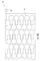
- the sheet of sensor patchesmay include about 30 to about 100 sensors.
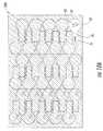
- the sensorsmay also be provided in a high density array of sensors where so many sensors are provided in a certain area of the high density array, for example, multiple sensors may be provided per square inch or per 3 by 3 inch regions of the high density array.
- Still other embodimentsare directed to sets of disposable single-use radiation dosimeter patches.
- the setscomprise a plurality of discrete disposable single-use dosimeter patches, each patch comprises a conformable body holding a circuit with an operational electronic component that changes a parameter in a detectable predictable manner when exposed to radiation, the body comprising opposing upper and lower primary surfaces and the dosimeter patch, in use and positioned on the patient, is devoid of externally hanging lead wires.
- the operational electronic componentmay be a radiation sensitive biased MOSFET or MOSFETs (such as MOSFET pairs) and the detectable operational parameter that changes can be the MOSFET threshold voltage(s).
- a medical grade adhesivemay be supplied on the lower primary surface of the sensor body such that the sensor may be adhered to the patient's skin.
- an adhesive coverlaymay be provide over the body of the sensor to secure the sensor to the patients skin.
- a buildup capis placed over the sensor patch to, for example, simulate placement of the sensor patch beneath the patient's skin. This type of simulation may help to focus and/or form equilibrium in the radiation beam in proximity to the sensor patch and, therefore, increase the reliability of radiation measurement.
- the buildup capmay simulate a distance of from about 1 to about 3 cm beneath the skin of the patient.
- the buildup capmay have a hemispherical shape and may be configured to hook onto the sensor patch.
- the buildup capmay include a layer of molded polystyrene and a layer of copper on the layer of molded polystyrene.
- the copper layermay have a thickness of from about 0.5 to about 1 mm and the polystyrene may have a diameter of from about 6 to about 7 mm.
- the computer program productcomprises a computer readable storage medium having computer readable program code embodied in the medium.
- the computer-readable program codecomprises: (a) computer readable program code for receiving pre-irradiation threshold voltage data associated with a plurality of disposable sensor patches; (b) computer readable program code for accepting data from a reader configured to electrically serially contact each of the plurality of disposable sensors for a short time; and (c) computer readable program code for determining the voltage threshold shift of the disposable sensor patches after radiation to determine the radiation exposure.
- a dose-readermay be adapted to receive a sensor patch in a sensor port.
- the sensor patchis also adapted to be inserted in the sensor port.
- the dose-readercan be a pocket or palm sized portable device.
- the dose-readermay also include a communications port, for example, a universal serial port (USB), RS 232 and the like, for downloading obtained data to a computer application or remote computer.
- the dose-reader functionalitymay be incorporated into a personal digital assistant (PDA) or other pervasive computer device.
- PDApersonal digital assistant
- a dose readermay be provided having a circuit integrated with the reader that is configured to communicate with an electronic memory of at least one single use dosimeter patch to obtain threshold data corresponding to a dose amount of radiation exposure the at least one sensor patch is exposed to in use and to prompt a user to provide predetermined data needed to determine the dose amount.
- the dose readermay be configured to automatically prompt the user of the reader for predetermined data before determining the radiation dose and automatically determine the radiation dose using the predetermined data.
- the predetermined datamay include a correction factor related to the at least one sensor patch.
- the sensor patchmay be configured to communicate with the dose-reader wirelessly.
- the sensor patch and the dose-readermay both be equipped with a radio frequency (RF) interface so that information may be shared between the two devices.
- RFradio frequency
- a test stripmay be provided.
- the test stripis sized and configured to be read by an external dose-reader.
- the test stripcan be sized and configured to be generally the same as a patch.
- the test stripmay include a conformable substrate holding a circuit.
- the circuitmay include a resistor and a voltage reference, operational parameters of which may be configured to change in a detectable predictable manner when exposed to radiation to indicate a calibrated status of the external reader.
- the voltage reference of the test stripincludes a 1.2 V shunt and the resistor includes comprises a 10 K ⁇ resistor.
- the circuitmay be adapted to engage with the external reader, compare a pre-radiation value to a post-radiation value to provide a comparison result and determine the state of the reader based on the comparison result.
- the circuitmay be configured to indicate that the external reader is functional if the comparison result is within a set of defined limits and that the external reader is not functional if the comparison result is outside the set of limits.
- FIG. 1is a schematic illustration of a patient undergoing radiation treatment according to some embodiments of the present invention.
- FIG. 2is a block diagram of operations for monitoring patients undergoing radiation treatments according to further embodiments of the present invention.
- FIGS. 3A and 3Bare illustrations of sets of disposable dosimeter patches according to still further embodiments of the present invention.
- FIG. 3Cis an anatomical map of sensor location according to some embodiments of the present invention.
- FIG. 4illustrates an exemplary patient information form according to some embodiments of the present invention.
- FIGS. 5A and 5Bare schematic illustrations of sensor placement on a patient according to further embodiments of the present invention.
- FIG. 6is a schematic illustration of embodiments of a reader contacting the sensor to obtain the radiation dosage data according to still further embodiments of the present invention.
- FIG. 7Ais a schematic illustration of further embodiments of a reader receiving the sensor in a sensor port to obtain the radiation dosage data according to some embodiments of the present invention.
- FIG. 7Bis a schematic illustration of still further embodiments of a reader receiving wireless communications from the sensor to obtain the radiation dosage data according to further embodiments of the present invention.
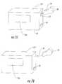
- FIG. 8Ais a greatly enlarged side view of a disposable radiation dosimeter according to still further embodiments of the present invention.
- FIG. 8Bis a top view of the dosimeter shown in FIG. 8A .
- FIG. 8Cis a partial cutaway view of a probe head for a reader according to some embodiments of the present invention.
- FIG. 9Ais a schematic of embodiments of a sensor patch with a circuit thereon according to further embodiments of the present invention.
- FIG. 9Bis a schematic of further embodiments of a sensor patch with a circuit thereon according to still further embodiments of the present invention.
- FIG. 9Cis a schematic of further embodiments of a sensor patch with a circuit thereon according to some embodiments of the present invention.
- FIG. 9Dis a schematic of further embodiments of a sensor patch according to further embodiments of the present invention.
- FIG. 9Eis a schematic of further embodiments of a sensor patch according to still further embodiments of the present invention.
- FIG. 10Ais a schematic illustration of a sheet of sensors according to some embodiments of the present invention.
- FIG. 10Bis yet another schematic illustration of a sheet of sensors according to further embodiments of the present invention.
- FIG. 10Cis a further schematic illustration of a sheet of sensors according to still further embodiments of the present invention.
- FIG. 10Dis still a further schematic illustration of a sheet of sensor patches according to some embodiments of the present invention.
- FIG. 11is a schematic of a circuit diagram of a MOSFET sensor with a reader interface and an optional memory according to some embodiments of the present invention.
- FIG. 12Ais a schematic of a threshold voltage reader circuit according to further embodiments of the present invention.
- FIG. 12Bis a graph of the change in the threshold voltage value versus radiation dose according to still further embodiments of the present invention.
- FIG. 13is a graph of the threshold voltage dependence on Ids using the voltage (V 0 ) of the reader illustrated in FIG. 12A .
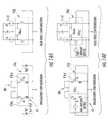
- FIG. 14Ais a schematic of a circuit diagram with a MOSFET pair, the left side of the figure corresponding to an irradiation operative configuration and the right side of the figure corresponding to a read dose operative configuration, according to some embodiments of the present invention.
- FIG. 14Bis a schematic of a circuit diagram with a MOSFET pair, the left side of the figure corresponding to an irradiation operative configuration and the right side of the figure corresponding to a read dose operative configuration, according to further embodiments of the present invention.
- FIG. 15Ais a schematic of a system or computer program product for estimating radiation based on data taken from a point contact-reader data acquisition system according to still further embodiments of the present invention.
- FIG. 15Bis a block diagram illustrating a reader device according to some embodiments of the present invention.
- FIG. 15Cis a block diagram illustrating a reader device according to further embodiments of the present invention.
- FIG. 16is a block diagram of a computer program having a radiation estimation module according to still further embodiments of the present invention.
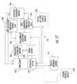
- FIG. 17is a block diagram of a point-contact reader data acquisition system some according to embodiments of the present invention.
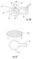
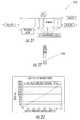
- FIGS. 18A and 18Bare schematic diagrams illustrating buildup caps according to further embodiments of the present invention.
- FIG. 19is a table including sensor specifications according to further embodiments of the present invention.
- FIG. 20is a block diagram illustrating functions of a reader device and a patch according to some embodiments of the present invention.
- FIG. 21is a block diagram illustrating a process for modifying conversion parameters and bias timing according some embodiments of the present invention.
- FIG. 22is a schematic diagram of a test strip according to further embodiments of the present invention.
- FIG. 23is a calibration curve illustrating a dose response of an exemplary MOSFET/RADFET according to still further embodiments of the present invention.
- FIG. 24is a graph illustrating an exemplary correction factor for energy dependence according to some embodiments of the present invention.
- FIG. 25is a table illustrating exemplary “k-factors” that may be applied to a dose equation according to further embodiments of the present invention.
- FIG. 26is a table illustrating an order of storing temperature correction coefficients according to still further embodiments of the present invention.
- FIG. 27is a table illustrating an order of storing fade correction coefficient according to some embodiments of the present invention.
- FIG. 28is a graph illustrating an exemplary response for fade in the RADFET voltage following a dose application according to further embodiments of the present invention.
- FIG. 29is a table including V/I relationships of readers according to still further embodiments of the present invention.
- FIG. 30is a table including a list of items included in an exemplary dose record according to some embodiments of the present invention.
- FIG. 31is a table including functional specifications of test strips according to further embodiments of the present invention.
- FIGS. 32A and 32Bis a table including functional specifications readers according to still further embodiments of the present invention.
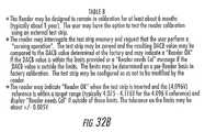
- FIG. 33is a table including functional specifications of patches according to some embodiments of the present invention.
- FIG. 1illustrates an example of a radiation system 10 with a radiation beam source 20 directed at a patient 50 having a tumor site.
- the patient 50can be positioned so as to be aligned and stationary with respect to the beam 20 b (illustrated by the diverging dotted lines) during the treatment.
- the patient 50can be arranged in any desired position depending on the direction of the beam, the location of the tumor, and the type of radiation therapy system employed.
- the patientis reclined, substantially flat and face up on a table so that the beam 20 b is directed into the targeted tumor site in the body as the patient undergoes radiation therapy in a treatment session.
- the patientwill undergo a plurality of successive treatment sessions over a treatment period.
- Each treatment sessionmay be planned to administer radiation doses of between about 1-2 Gray (100-200 cGy) with an overall typical treatment limit of about 35-80 Gray.
- At least one disposable single-use dosimeter sensor patch 30can be positioned externally on the skin of the patient 50 .
- “single-use”is used to refer to a use for a single patient during a treatment session.
- the sensor patch 30is typically worn once proximate in time and during a treatment. In other embodiments, the sensor patch 30 may be episodically worn or continuously worn over a target period.
- a treatment sessionmay include an active radiotherapy administration during a single treatment session or serially spaced apart treatment sessions.
- the treatment sessionmay have a duration of minutes, hours, days and the like.
- a calibration dose obtained before the sensor patch 30 is positioned on a patientis not to be considered the “single-use.”
- a plurality of sensor patches 30are located both on the front and back of the patient 50 .
- the sensor patches 30are configured to change an operational parameter in a predictable manner that correlates to radiation dose it receives, as will be discussed further below.
- the sensor patch 30can be configured so as to be self-contained and discrete and devoid of dangling lead wires extending to a remote power source or operating system during use and in position on the patient.
- a readerfor example, reader 75 ( FIGS. 6 and 7 ), can be configured to obtain the data from the sensor patch 30 by, for example, electrically contacting with each sensor patch 30 of interest.
- the reference number “ 75 ”will be used to refer generally to a reader device according to embodiments of the present invention. Particular embodiments of a reader device 75 may be referred to using the reference number 75 and one or more primes attached thereto. For example, particular embodiments of the reader device may be denoted 75 ′ or 75 ′′. This convention may similarly be used with respect to other features of the present invention. For example, the reference number “ 30 ′” will be used to refer to particular embodiments of a sensor patch herein. It will be understood that features discussed with respect to any embodiment of the present invention may be incorporated into other embodiments of the present invention even if these features are not discussed specifically with reference to each individual embodiment.
- At least one single-use dosimeter sensor patchcan be releasably secured to the skin of the patient (block 100 ).
- the sensor patchmay be calibrated and/or pre-dosed before being attached to the patient (block 101 ).
- the calibration and/or pre-dosing of the sensor patchmay be done on an individual patch basis or many sensor patches may be calibrated and/or pre-dosed in batches simultaneously as discussed further below.
- the patch(es)can be conveniently attached to the patient in operation-ready condition before the patient enters the radiation treatment room or chamber (block 102 ) to limit or reduce the set-up time required or the “down-time” of the equipment or the treatment room.
- the sensor patch or patchesmay be secured to the patient prior to his/her entry into the radiation treatment room.
- a pre-irradiation or pre-dose measurement or reading of data associated with an operational parameter of the sensor patch(es) 30can be obtained prior to initiation of the radiation treatment (block 105 ).
- the datacan be obtained in situ, with the sensor patch(es) 30 in position on the patient.
- the pre-dose datacan be established prior to positioning the sensor patch(es) onto the subject as discussed above and the data then transferred to the reader or associated controller and/or computer at a desired time.
- the post-radiation readingcan be taken when the patient leaves the treatment room to evaluate the dose delivered during the treatment session to limit the amount of room-use time.
- the sensor patches 30can be removed from the patient and then read by a handheld portable and/or a bench top reader. In other embodiments, the reading can be obtained while the sensor patches 30 remain on the patient. In certain particular embodiments, the reading may be able to be obtained in situ during the treatment session (without removing the sensor patch(es) from the patient) to provide real-time feedback to the clinician estimating whether the desired dose is being administered to the patient.
- the temperature of the sensor patch(such as at a location adjacent the circuitry) or of the subject (skin or core body) can also be ascertained or obtained and taken into account when calculating the radiation dose.
- the dose readingcan be obtained without requiring external powering or externally applied biasing of the sensor patches 30 during the radiation treatment.
- a plurality of discrete sensor patches 30can be positioned to cover a region on the skin that is in the radiation beam path so as to reside over the tumor site.
- one or more sensor patches 30can also be positioned in radiation sensitive areas of the body to confirm stray radiation is not unduly transmitted thereto.
- FIG. 1illustrates that a sensor patch can be located at the neck over the thyroid when the tumor site is over the chest region.
- sensitive regionsinclude, but are not limited to, the thyroid, the spine, the heart, the lungs, the brain, and the like.
- radiationis administered to the patient in a first treatment session (block 110 ).
- Data associated with a change in an operational parameter in the dosimeter sensor patch circuitrymay be obtained from the sensor patch using a reader device (block 120 ) after administering the radiation to the patient (block 110 ).
- a sensor patchmay be removed from the patient and inserted into the reader device to transfer the data from the sensor patch.
- the reader devicemay contact the sensor patch as discussed further below.
- the readermay transfer data from the sensor patch wirelessly.
- the radiation dose received by the patientcan be determined based on the obtained data (block 125 ).
- the obtained datamay include a voltage threshold of a metal-oxide semiconductor field-effect transistor (MOSFET) included on the at least one sensor patch 30 .
- MOSFETmetal-oxide semiconductor field-effect transistor
- a pre-radiation voltage threshold of the MOSFET and a zero temperature coefficient of the MOSFETmay be measured before the patient undergoes radiation therapy (block 108 ).
- the pre-radiation threshold voltage and the zero temperature coefficient of the MOSFETmay be stored in the electronic memory of the at least one sensor patch (blocks 109 and 130 ).
- the stored zero temperature coefficientmay be used to bias the MOSFET (block 124 ) on the at least one sensor patch 30 after the patient undergoes radiation therapy and before the post-radiation threshold voltage is measured as discussed further below.
- the radiation dosemay be automatically determined by the reader 75 without any input by a doctor or technician.
- the doctor or technicianmay be prompted for additional information (block 123 ) by the reader 75 to determine the radiation dose.
- the reader 75may prompt the technician for a correction factor related to the sensor patch 30 and/or, radiation type, equipment set-up and the like. The prompts may be carried out before and/or after the irradiation.
- the reader 75may automatically determine the radiation dose using the additional information provided.
- the obtained data, as well as other informationmay be stored in an electronic memory (memory device) included on the sensor patch (block 130 ).
- the electronic memorymay include methodology data that instructs the reader 75 how to interface with, i.e., obtain data from, the sensor patch(es) 30 .
- the electronic memorymay include methodology data that instructs the reader 75 how to interface with, i.e., obtain data from, the sensor patch(es) 30 .
- the patch 30changes electronic configuration, the patch 30 can be configured to automatically instruct the reader 75 on how to obtain the radiation and other patch data of interest, allowing the reader 75 to operate with different versions of patches.
- the reader 75can be periodically upgraded with software to communicate with the different versions of patches. Combinations of these configurations may also be used.
- the electronic memorymay further include radiation-dose data, patient data, time and date of a radiation reading, calibration data and the like. Furthermore, as discussed above, the electronic memory may include the zero temperature coefficient of a MOSFET included on the sensor patch 30 . This zero temperature coefficient may be used to bias the MOSFET after the radiation treatment before a post-radiation threshold voltage is obtained as discussed further below.
- the sensor patch 30does not require lead wires extending from a remote power source or computer system to operate (i.e., is basically inactive and/or unpowered) during irradiation.
- a remote power source or computer systemi.e., is basically inactive and/or unpowered
- the MOSFETis generally passive but collects a permanent space charge as a result of the passage of ionizing radiation.
- the biosensor(s)can be inductively powered and the MOSFET-based radiation data can be wirelessly transferred to a remote reader.
- the sensor patch 30is configured to be a discrete patch(es) (or a patch array of sensors).
- the patch 30can transmit or relay radiation data upon contact with and/or insertion into a reader device 75 and may store data in an electronic memory device included on the sensor patch.
- the sensor patch 30may be configured to communicate wirelessly with the reader 75 .
- the radiation dose received by the sensor patch 30can be determined and used to estimate the dose received by the patient during the radiation therapy session based on the data obtained by the reader.
- the reader 75itself can be a handheld portable unit that may or may not require wires to connect with a remote controller or computer or may use a standard communication port as will be discussed further below.
- the reader 75can include a user input such as a touch screen and/or keypad entry.
- the operationscan be carried out for each or a selected radiation treatment session. If the operations are repeated for each treatment session, a cumulative amount of delivered radiation can be estimated/confirmed to allow a clinician to evaluate whether additional treatments are desired.
- FIG. 3Aillustrates that the sensor patches 30 can be provided in a kit or set 130 including a plurality of sensors 30 p .
- the plurality of sensors 30 pmay be configured in sufficient numbers or types for a single patient or so as to be able to supply sensors across a plurality of patients.
- a strip of six sensor patches 30can be packaged together as a set 130 ′ as shown in FIG. 15A . It is contemplated that, depending on the treatment type, the treatment location, the tumor site, and the like, different numbers of sensor patches 30 may be used for different patients.
- the kit 130may include from about 2 to about 10 or more sensor patches 30 that can be selectively chosen for use by the clinician.
- Each sensor patch 30can be sterilized and sealed in a sterile package or the kit 130 itself can be sized and configured to hold a plurality of the sensor patches 30 p in a sterile package that, once opened, can be either used or discarded.
- the sensor kit 130is sized for multi-patient use, then larger quantities may be packaged individually, or in sets within the multi-patient package, together.
- the sterilizationcan be performed by heat or chemical exposure, such as by ethylene oxide sterilization. In certain embodiments, sterilization and/or sterile packaging may not be required.
- each sensor patch 30can be packaged with pre-irradiation characterizing data 132 .
- This data 132can be included in optically or electronically readable formats such as in bar code format for the reader to be able to read without having the clinician enter the information into a controller/computer.
- the data 132may be included in a memory storage device 67 , for example, an electrically programmable memory such as an electrically erasable read only programmable memory (EEPROM), provided on each sensor patch 30 p as discussed further below.
- the memory storage device 67may include information such as patient identification, time, date, hospital, therapist, state of the device, dosed/undosed sensor data and calibration data.
- the memory storage device 67may further be used to store bias parameters and/or information with respect to measurement methodology for each individual patch 30 .
- the measurement methodologymay include instructions for the reader 75 on how to communicate with the sensor patch 30 . Including these instructions in the memory storage device may allow the reader 75 to operate with any version of the sensor patch 30 as the reader 75 may not have to be configured for the specifications of a particular sensor patch 30 .
- the memory storage device 67 of the sensor patch 30may have at least 2 K of storage thereon.
- Each sensor patch 30can have an individual calibration coefficient, dose data or characterizing data label located on the sensor patch 30 or as a corresponding label held with the package or kit 130 .
- each sensor patch 30 produced in a common production run (off of the same wafer or chip) with substantially similar characterizing datamay be packaged together and a single calibration characterizing data or label 132 can be included with the set 130 or sets or production run.
- the calibration related characterizing datacan include the pre-irradiation threshold voltage value of a MOSFET(s) that is measured at an OEM and provided in or with the sensor patch set 130 .
- the memory storage device 67may include a zero temperature bias parameters associated with the MOSFET included on the sensor patch 30 .
- the zero temperature coefficient of the MOSFETmay be measured prior to administration of radiation therapy to the patient and stored in the memory storage device 67 .
- the zero temperature coefficient of the MOSFETmay be used to bias the MOSFET before obtaining a post-radiation threshold voltage value of the MOSFET as discussed further below.
- Table 1summarizes exemplary specifications for the sensor patch 30 according to some embodiments of the present invention. It will be understood that the specifications provided in Table 1 are provided for exemplary purposes only and that embodiments of the present invention should not be limited to this configuration.
- identifying indiciamay be disposed on the sensor patches 30 to allow a clinician to easily visually identify and/or account for the sensors used.
- FIG. 3Aillustrates three discrete sensor patches labeled as 1 F, 2 F, and 3 F as well as a sensor with a pictorial representation of a heart 4 F (other visual images can also be used such as a yellow caution sign, other anatomical symbols, and the like).
- the patchesmay be configured to accept direct indicia using, for example, a marker or a pen thereon.
- the heart or caution sensor patch 30 scan be positioned in a radiation sensitive area to detect the amount of radiation delivered to that area.
- the radiation beamis adjusted to reduce the radiation exposure to sensitive areas and a caution-sensitive sensor patch 30 s (or patches) can indicate whether adjustments need to be made to reduce the detected exposure for each or selected treatment sessions.
- the sensor patches 30 s used for sensitive detectionmay be configured with increased sensitivity for enhanced dose resolution capability for measuring small, residual, or stray doses of radiation (such as those located over critical organs which are not in the treatment volume).
- the “normal” single use sensorsmay be configured to operate over a range of between about 20-500 cGy; the “high sensitivity” sensor might be configured to operate from about 1-50 cGy.
- the circuit 30 cFIG.
- the high sensitivity sensor 30 sincludes at least one radiation-sensitive field-effect transistor (RADFET) that can be configured to produce a larger threshold voltage shift for a given amount of received or absorbed dose relative to the sensors 30 positioned in the window of the targeted treatment volume.
- the larger voltage shiftmay increase dose resolution and possibly dose repeatability.
- single-use dosimeterscan be optimized to work over a much lower dose range than multiple use dosimeters. Since the typical per day fraction for radiation therapy is about 200 cGy, the dosimeter sensor 30 can be optimized for accuracy and repeatability over this dose range. A 20-500 cGy operating range should meet performance goals while providing adequate flexibility for varying treatment plans. A multiple-session fraction dosimeter sensor 30 may require a much larger dose range that depends on the number of fractions over which the sensor will operate.
- “disposable”means that the sensor patch is not reusable and can be disposed of or placed in the patient's records.
- the indiciacan include an alphanumeric identifier such as the letter “F” located to be externally visible on the sensor patches 30 .
- the letter “F”can represent that the sensors are placed on a first side or front of the patient.
- FIG. 3Billustrates that a second set of sensors 130 ′ can be supplied, these sensor patches 30 can be labeled with different indicia, such as 1 B, 2 B, 3 B and the like, representing that they are located at a different location relative to the first set (such as a second side or back of the patient).
- Using data from opposing outer surfacescan allow an interpolated radiation dose amount to be established for the internal tumor site.
- indicia described abovenamely “F” and “B”, are provided herein for exemplary purposes only and that indicia according to embodiments of the present invention are not limited by the examples provided. Any label, mark, color or the like may be used that would serve to distinguish one patch or set of patches from another patch or set of patches without departing from the teachings of the present invention.
- the first set of patches 130may be blue and the second set of patches 130 ′ may be red.
- the indiciamay be, for example, on the sensor patch itself or on an adhesive covering placed on or over the sensor patch without departing from the teachings of the present invention.
- FIG. 3Cillustrates a patient anatomical map 150 that can be used to identify where each of the sensor patches 30 are placed on the body of the patient.
- the map 150may be stored in the patient chart or file.
- the cliniciancan allocate the same sensor patch identifier (“A”, “ 1 F”, etc. . . . ) to the same location.
- the map 150 and/or indicia on the sensor patches 30can, in turn, help the clinician consistently identify whether a particular location may have undue or deficient exposure.
- sensor patch F 1indicates a low radiation exposure
- F 3indicates a relatively high exposure
- the twoare positioned in the targeted beam region
- either one or both of the sensor patches 30is not functioning properly, or the radiation beam may need adjustment.
- Using substantially the same sensor patch position for successive treatment sessionsmay allow cumulative radiation dose data to be obtained and correlated to provide a more reliable indication of dose.
- the clinicianmay also draw markings on the patient's skin to help align the sensor patches 30 in relation thereto over the different treatments sessions.
- the discrete sensor patches 30can be arranged to reside on a common substrate or to be attached to each other so as to define known or constant distances therebetween (not shown).
- the sensor patches 30may be configured to be at the body temperature of the patient during use or at room temperature, or temperatures in between.
- a temperature readingmay be obtained, assumed, or estimated.
- the temperaturemay impact the operational change if substantially different from that upon which the calibration data is established.
- the at least one sensor patch 30can be used with other therapies that generate radiation and potentially expose a patient to radiation.
- at least one sensor patch 30can be mounted to a patient during a fluoroscopic procedure to evaluate the skin radiation exposure.
- a first set-up pre-dose verification protocolcan be carried out to deliver a first radiation dose and a first radiation dose value can be obtained for at least one selected patch to confirm that the radiation beam focus location is correct or suitable (or whether a sensitive area is receiving radiation).
- the systemcan be configured to map a dose gradient by correlating the determined radiation dose values at each patch location to the anatomical location on the subject of each patch.
- FIG. 4illustrates an exemplary patient dosimetry form 99 , which may be, for example, a paper sheet or computer printable document.
- the form 99can contain an anatomical map 150 as discussed above with respect to FIG. 3C .
- Sicel Technologies, Inc.asserts copyright protection for the form illustrated in FIG. 4 and has no objection to reproduction of the patent document, as it appears in the Patent and Trademark Office patent file or records, but reserves all other rights whatsoever.
- the map 150may be used to identify and/or memorialize for the patient record where each of the sensor patches 30 are placed on the body of the patient during use.
- An anatomical map 150can be used to record the specifics of each radiation session and may be placed in each patient's chart or file to assist the doctor and/or clinician.
- Patients being treated on an ongoing basismay have multiple dosimetry forms 99 in their chart and/or file corresponding to each treatment session.
- the cliniciancan, as desired, allocate the same sensor patch identifier to the same location aided by the map 150 .
- the dosimetry form 99may further include a dosimetry plan portion 152 , a measurement data portion 154 and a sensor patch record portion 156 .
- the dosimetry plan portion 152may include the patient's name, the date or dates the patient is scheduled for the treatment, the patient's doctor, and any information that may be specific to the patient or the patient's treatment.
- the measurement data portion 154may include information such as the date of the treatment and the therapist administering the treatment on that date.
- the sensor patch record portion 156may include labeled sections 158 (A, B, . . . ) giving each patient a discrete identifier which may correspond to sensor patch locations (A, B, . . . ) with the identifiers indicated on the anatomical map 150 .
- the sensor patch record portion 156may further include dosing data, for example, target and measured doses as illustrated in FIG. 4 .
- the sensor patch record portion 156may further include the actual sensor patch used on the patient in each of the labeled sections 158 .
- the form 99can include two separate storage regions, namely a pre and post dose use storage region.
- the form 99can also allow a clinician to indicate whether the sensor patch was held in the entrance and/or exit field.
- the sensor patch 30may contain a storage or memory device 67 ( FIGS. 3A , 9 B), the storage or memory device on the sensor patches may be accessed to determine dosing information etc. if this information fails to be recorded, is misplaced or requires verification.
- the memory device 67 included on the sensor patch 30may further include the data recorded in the map portion 150 , the dosimetry plan portion 152 and the measurement data portion 154 of the dosimetry form 99 . Accordingly, the memory device 67 on the sensor patch 30 may serve as an electronic dosimetry patient record form. It will be understood that the dosimetry form 99 of FIG. 4 is provided for exemplary purposes only and that the present invention may provide data and/or hold sensor patches in alternate manners without departing from the teachings of the present invention.
- FIG. 5Aillustrates the use of five primary sensor patches 30 positioned over the targeted treatment region (on the front side of the patient) and one sensor patch 30 s positioned over the heart.
- FIG. 5Billustrates three primary sensors 30 located over the back surface proximate the area corresponding to the underlying tumor site 25 .
- FIG. 6illustrates a reader or data acquisition device 75 ′ according to embodiments of the present invention, in point contact with the underlying sensor patch 30 in order to detect the amount of radiation that the sensor patch 30 was exposed to during (or after) the treatment session.
- the sensor patch(es) 30can be secured to a patient's chart or dosimetry form 150 and read after removal from the patient.
- the reader 75 ′ illustrated in FIG. 6may be configured to contact a portion of an electrical circuit on the sensor patch 30 that includes a device that has an operating characteristic or parameter that changes upon exposure to radiation in a predictable manner to allow radiation doses to be determined.
- the reader 75 ′can be configured with a probe 75 p that is configured to electrically contact an electrically conductive probe region on the sensor patch 30 so as to obtain a reading in a “short” time of under about 30 seconds, and typically in less than about 5-10 seconds, for each of the sensor patches 30 .
- FIG. 7Aa sensor patch 30 ′ disposed in a reader or data acquisition device 75 ′′ according to further embodiments of the present invention.
- Sensor patches 30 ′may be adapted to be inserted into the reader 75 ′′.
- the reader 75 ′′is adapted to receive the sensor patch 30 ′.
- the sensor patch 30 ′is formed to include a tab portion 36 that at least a portion of is sufficiently rigid to sustain its shape for proper electrical coupling when inserted into a port 32 in the reader device 75 ′′.
- FIG. 7Aa sensor patch 30 ′ disposed in a reader or data acquisition device 75 ′′ according to further embodiments of the present invention.
- Sensor patches 30 ′may be adapted to be inserted into the reader 75 ′′.
- the reader 75 ′′is adapted to receive the sensor patch 30 ′.
- the sensor patch 30 ′is formed to include a tab portion 36 that at least a portion of is sufficiently rigid to sustain its shape for proper electrical coupling when inserted into a port 32 in the reader device 75
- the reader 75 ′′may include a sensor port 32 and the sensor patch 30 ′ may be inserted into the port 32 in the reader 75 ′′ in order to detect the amount of radiation that the sensor patch 30 ′ was exposed to.
- the port 32can read the sensor patch 30 as it is held in selected orientations in the port 32 .
- the port 32may be configured similar to conventional devices that read, for example, glucose strip sensors and the like.
- the port 32 illustrated in FIG. 7Amay contain one or more electrical contacts configured to contact one or more electrical contacts on the sensor patch 30 ′ to electrically connect the reader 75 ′′ to an electrical circuit on the sensor patch 30 ′.
- the electrical circuit on the sensor patch 30 ′includes a radiation-sensitive component that has an operating characteristic or parameter that changes upon exposure to radiation in a predictable manner to allow radiation doses to be determined.
- the reader 75 ′′may obtain a reading in under about 30 seconds, and typically in less than about 5-10 seconds, for each of the sensor patches 30 .
- the reader device 75 ′′can be held in a portable housing 37 . It may be pocket sized and battery powered. In certain embodiments, the reader device 75 may be rechargeable. As shown in FIGS. 7 , 15 A and 15 B, the reader 75 may include a display portion 75 d , for example, a liquid crystal display (LCD), to provide an interface to depict data to the doctor and/or technician.
- a display portion 75 dfor example, a liquid crystal display (LCD), to provide an interface to depict data to the doctor and/or technician.
- LCDliquid crystal display
- the function of the reader device 75may be incorporated into any portable device adapted to receive a sensor patch 30 in, for example, a sensor port 32 .
- the reader 75 functionality/circuitrycould be disposed in a personal digital assistant (PDA) that is adapted to include a radiation sensor port 32 .
- PDApersonal digital assistant
- the reader 75may further include a remote computer port 33 .
- the port 33may be, for example, RS 232, infrared data association (IrDA) or universal serial bus (USB), and may be used to download radiation and/or other selected data from the sensor patch 30 to a computer application or remote computer.
- the sensor patch 30 and the reader device 75 ′′′may both be equipped with a radio frequency (RF) interface and information may be shared between the reader device 75 ′′′ and the sensor patch 30 using wireless signals 38 without departing from the scope of the present invention.
- RFradio frequency
- Exemplary embodiments of a reader 75 according to embodiments of the present inventionare provided in commonly assigned U.S. Design patent application Ser. No. 29/197,934 entitled Portable Oncologic External Dosimeter Reader, filed Jan. 21, 2004, the content of which are hereby incorporated herein by reference as if set forth in its entirety.
- the sensor patch 30includes a storage or memory device 67 .
- the reader 75may be configured to obtain data stored in the memory device 67 of the sensor patch 30 using, for example, electrical contacts on the reader 75 and the patch 30 , to transfer the data stored in the memory device 67 of the sensor patch 30 .
- This data obtained from the sensor patch memory device 67may, for example, be stored locally on the reader 75 or be downloaded to an application on, for example, a remote computer using a port 33 provided in the reader 75 .
- the memory device 67 on the sensor patch 30may serve as a permanent record of the radiation dose and may contain a real time clock such that the obtained data may include a time and date stamp.
- FIG. 20An exemplary block diagram of a reader 75 and a sensor patch 30 including a RADFET 63 and an electronic memory 67 according to some embodiments of the present invention is provided in FIG. 20 . It will be understood that the block diagram of the reader 75 and the sensor patch 30 of FIG. 7B is provided for exemplary purposes only and embodiments of the present invention should not be limited to the configuration provided therein. Furthermore, a flow diagram 2100 of FIG. 21 illustrates how a number of reads, a read delay and/or a rate may modify conversion parameters of the RADFET according to some embodiments of the present invention.
- FIG. 8Aillustrates exemplary embodiments of a sensor patch 30 .
- the sensor patch 30includes a substrate layer 60 , a circuit layer 61 , and an upper layer 62 that may be defined by a coating, film, or coverlay material.
- the substrate layer 60can be selected such that it is resilient, compliant, or substantially conformable to the skin of the patient. Examples of suitable substrate layer materials include, but are not limited to, Kapton, neoprene, polymers, co-polymers, blends and derivatives thereof, and the like.
- the underside or bottom of the sensor patch 30 bmay include a releasable adhesive 30 a so as to be able to attach to the skin of the patient.
- the adhesive 30 acan be a medical grade releasable adhesive to allow the sensor patch 30 to be secured to the skin during the treatment session and then easily removed without harming the skin.
- the adhesive 30 acan be applied to portions, or all, of the bottom surface of the substrate layer 60 .
- a releasable linercan be used to cover the adhesive, at least prior to positioning on the patient.
- the underside of the sensor patch 30 bmay be free of the adhesive.
- an adhesive coverlay 30 cl( FIG. 9C ) may be placed over the body of the sensor patch 30 to secure the sensor patch 30 to the patient.
- the adhesive coverlay 30 clmay be sized to extend beyond the outer perimeter of the sensor substrate 60 .
- the adhesivemay be on a portion or all of the underside of the coverlay 30 cl.
- the sensor patch(es) 30is configured as a discrete, low profile, compact non-invasive and minimally obtrusive device that conforms to the skin of the patient.
- the sensor patch(es)may be less from about 0.25 to about 1.5 inches long and wide and have a thin thickness of from about 1 to about 5 mm or less.
- the sensor patches 30can, in certain particular embodiments, be secured to the patient and allowed to reside thereon for a plurality or all of the successive treatments.
- the sensor patches 30can be configured to reside on the patient in its desired position for a 1-4 week, and typically about a 1-2 week period. In this manner, the same sensor patches 30 can be used to track cumulative doses (as well as the dose at each treatment session).
- An adhesivemay be applied in a quantity and type so as to be sufficiently strong to withstand normal life functions (showers, etc.) during this time.
- selected ones of the sensor patches 30can also be replaced as desired over the course of treatment as needed or desired.
- the sensor patch 30can be attached to the patient so that it makes and retains snug contact with the patient's skin. Air gaps between the sensor 30 and the patient's skin may cause complications with respect to obtaining the estimated dosage data.
- some embodiments of the present inventioninclude the placement of an overlay material 30 fl over the sensor patch 30 to, for example, simulate placement of the sensor patch 30 beneath the patient's skin. This type of simulation may inhibit scatter of the radiation beam and/or establish electronic equilibrium in proximity to the sensor patch 30 and, therefore, increase the reliability of radiation measurement.
- Radiation measurement using the sensor subsurface electronicsmay be optimal at from about 0.5 to about 3 cm beneath the patient's skin, but typically is from about 1 to about 1.5 cm beneath the patient's skin. Accordingly, the overlay material 30 fl may be from about 0.5 to about 3 cm thick to simulate subsurface depth measurement conditions. The presence of this overlay material 30 fl may decrease the influence of air gaps between the sensor 30 and the patient's skin.
- the overlay material 30 flmay be, for example, a resilient flubber like or flexible material that will conform to the skin such as an elastomeric or the like. As illustrated in FIG. 9D , the overlay material 30 fl may be placed between the adhesive coverlay 30 cl and the sensor patch 30 such that the adhesive coverlay 30 cl adheres the sensor patch 30 and the overlay material 30 fl to the patient's skin. As illustrated in FIG. 9E , the overlay material 30 fl may be placed over the adhesive coverlay 30 cl and the sensor patch 30 . In certain embodiments, the overlay material may have adhesive properties such that the overlay 30 fl may be adhered to the patient's skin. The overlay material 30 fl may also be integrated with the sensor patch 30 without departing from the teachings of the present invention.
- some embodiments of the present inventioninclude the placement of a buildup cap 180 over the sensor patch 30 to, for example, simulate placement of the sensor patch 30 beneath the patient's skin. This type of simulation may help to focus a narrow portion of the radiation beam in proximity to the sensor patch 30 and, therefore, increase the reliability of radiation measurement.
- the buildup cap 180may have a hemispherical shape and may simulate placement of the sensor patch 30 inside the body to a depth called “Dmax”. Dmax may be, for example, from about 1 to about 3 cm and is the depth at which the absorbed dose reaches a maximum for a given energy.
- the buildup cap 180may include a material equivalent to water and a metallic material.
- the buildup cap 180may include a layer of polystyrene 182 having a diameter of from about 6 to about 7 mm and a layer of copper 181 on the polystyrene have a thickness of about 0.5 to about 1 mm.
- the buildup cap 180may include a small lip (not shown) that hooks onto the front edge of the patch for consistent alignment.
- the buildup cap 180may have a medical grade adhesive that would stick well, but not permanently, to the top face of the sensor patch 30 .
- the geometry of the capcould be made to help with isotropy.
- the buildup cap 180may be placed on the sensor patch 30 separately based on the energy range of the buildup cap 180 , thereby allowing the underlying sensor patch 30 to be used with different buildup caps 180 for different energy ranges.
- the buildup caps 180may be provided in different colors, the colors indicating the energy range of the buildup cap 180 .
- the bulk of the buildup cap 180may be injection molded polystyrene 182 that is coated with a copper layer 181 and some rubbery or elastomeric surface paint applied in different colors corresponding to the different energy ranges provided by the buildup cap 180 .
- the buildup cap 180can also be shaped to provide a measurement that is independent of X-ray beam entry angle.
- the buildup cap 180may be placed between the adhesive coverlay 30 cl and the sensor patch 30 such that the adhesive coverlay 30 cl adheres the sensor patch 30 and the buildup cap 180 to the patient's skin. It will be further understood that the buildup cap 180 may also be placed over the adhesive coverlay 30 cl and the sensor patch 30 without departing from the scope of the present invention
- the sensor circuit layer 61can be attached to, and/or formed on, the underlying substrate layer 60 .
- the upper layer 62can be configured as a moisture inhibitor or barrier layer that can be applied over all, or selected portions of, the underlying circuit layer 61 . It is noted that, as shown, the thickness of the layers 60 - 62 are exaggerated for clarity and shown as the same relative thickness, however the thickness of the layers may vary.
- the sensor patch 30is configured as a low profile, thin device that, when viewed from the side, is substantially planar.
- FIG. 8Bis a top view of embodiments of a sensor patch 30 .
- the circuit layermay include two conductive probe contacting regions 30 p .
- the probe contacting regions 30 pare configured to provide the connections between the operating circuitry on the circuit layer 61 and the external reader.
- the probe contacting region(s) 30 pcan be directly accessible or covered with a protective upper layer 62 . If directly accessible, during operation, the reader 75 can merely press against, contact or clip to the sensor patch 30 to contact the exposed surface of the conductive probe region 30 p to obtain the reading.
- an upper layer 62that is a protective coating or other non-conductive insulator material, the clinician may need to form an opening into the coating or upper layer over the region 30 p so as to be able to penetrate into the sensor patch 30 ′ a certain depth to make electrical contact between the probe region 30 p and the probe of the reader 75 p.
- FIG. 8Cillustrates a probe portion 75 p of the reader 75 ′ of FIG. 6 .
- the probe portion 75 pmay be configured so that the probe 75 p includes, for example, conductive calipers, pinchers, or other piercing means, that can penetrate to make electrical contact with the probe contacting region 30 p of the sensor patch.
- FIG. 9Aillustrates a top view of embodiments of a circuit layer 61 .
- the circuit layer 61includes the radiation sensitive operative sensor patch circuitry 30 c that is self-contained and devoid of outwardly extending or hanging lead wires that connects to an operational member.
- the sensor patch circuitry 30 cincludes a radiation sensitive device 63 that exhibits a detectable operational change when exposed to radiation.
- the radiation sensitive device 63is a miniaturized semiconductor component such as a MOSFET. Suitable MOSFETs include RADFETs available from NMRC of Cork, Ireland.
- the MOSFETmay be sized and configured to be about 0.5-2 mm in width and length.
- the circuitry 30 calso includes at least one conductive lead or trace 64 extending from the radiation sensitive device 63 to the conductive probe contacting region 30 p .
- the conductive probe contacting region 30 pis an annular ring.
- the traces or leads 64 ′may be formed, placed, or deposited onto the substrate layer 60 in any suitable manner including, but not limited to, applying conductive ink or paint or metal spray deposition on the surface thereof in a suitable metallic pattern, or using wires.
- an upper layer 62such as described above (such as epoxy) may be formed over the circuit layer 61 (or even the entire sensor patch).
- the sensor patch 30may include integrated Electro Static Discharge (ESD) protection, the reader 75 may include ESD protection components, or the user/operator may use ESD straps and the like during readings.
- ESDElectro Static Discharge
- the sensor patch 30 and circuit 30 ccan be configured with two or more MOSFETS.
- onemay be positioned over the other on opposing sides of the substrate in face-to-face alignment to inhibit orientation influence of the substrate. (not shown).
- other materialse.g., certain epoxies, can be used to both encapsulate the MOSFETs and provide further scattering influence to facilitate isotropic response of the MOSFETs.
- the backscatter effectcan be taken into account when calculating an entrance or exit dose or sufficient build-up may be provided on the top of the dosimeter to promote the equilibration of scattered electrons. See, Cancer, Principles and Practice of Oncology, 3d edition, ed. V T DeVita, S. Hellman, and S A Rosenberg (JB Lippincott Co., Phila., 1989), the contents of which are hereby incorporated by reference as if recited in full herein.
- FIG. 9Bis a top view of further embodiments of a sensor patch 30 ′ that includes a tab portion 36 that is adapted to be received by a reader, for example, reader 75 ′′ illustrated in FIG. 7 .
- the circuit 30 c ′includes a circuit layer 61 that includes at least one electrical contact 31 shown as a plurality of substantially parallel leads.
- the sensor patch 30 ′is inserted into the reader port 32 of the reader 75 ′′ ( FIG. 7 ) and the at least one electrical contact 31 is configured to provide the electrical connections between the operating circuitry on the circuit layer 61 and the external reader 75 ′′.
- the electrical contact(s) 31may be covered with a protective upper layer 62 ( FIG. 8A ).
- an upper layer 62that is a protective coating or other non-conductive insulator material, the clinician may need to form an opening into the coating or upper layer over the electrical contact(s) 31 so these contact(s) 31 may make electrical contact with the reader via sensor port 32 ( FIG. 7 ).
- FIG. 9Bfurther illustrates the circuit layer 61 that includes the radiation sensitive operative sensor patch circuitry 30 c ′.
- the sensor patch circuitry 30 c ′includes a radiation sensitive device 63 that exhibits a detectable operational change when exposed to radiation and may include a memory device 67 .
- the radiation sensitive device 63is a miniaturized semiconductor component such as a MOSFET. Suitable MOSFETs include RADFETs available from NMRC of Cork, Ireland. In certain embodiments, the MOSFET may be sized and configured to be about 0.5-2 mm in width and length.
- the circuitry 30 c ′also includes at least one conductive lead or trace 64 ′ extending from the radiation sensitive device 63 and/or the memory device 67 to the at least one electrical contact(s) 31 .
- the traces or leads 64 ′may be formed, placed, or deposited onto the substrate layer 60 in any suitable manner including, but not limited to, applying conductive ink or paint or metal spray deposition on the surface thereof in a suitable metallic pattern, or using wires.
- an upper layer 62such as described above (such as epoxy) may be formed over the circuit layer 61 (or even the entire sensor patch).
- Each sensor patch 30may be from about 0.25 to about 1.5 inches long and wide and have a thin thickness of from about 1 to about 5 mm or less.
- the underside or bottom of the sensor patch 30 bmay include a releasable adhesive 30 a so as to be able to attach to the skin of the patient.
- the adhesive 30 acan be a medical grade releasable adhesive to allow the sensor patch 30 to be secured to the skin during the treatment session and then easily removed without harming the skin.
- the adhesive 30 acan be applied to portions, or all, of the bottom surface of the substrate layer 60 .
- the underside of the sensor patch 30 bmay be free of the adhesive.
- an adhesive coverlay 30 clmay be placed over the entire body of the sensor patch 30 to secure the sensor patch 30 to the patient.
- the adhesive coverlay 30 clmay be sized to extend beyond the outer perimeter of the sensor substrate 60 and leave the tab portion 36 of the sensor 30 ′ exposed.
- the adhesive provided on the underside of the coverlay 30 clmay be provided on a portion of the coverlay 30 cl , for example, the portion of the coverlay 30 cl contacting the patient's skin outside the perimeter of the sensor substrate 60 , or on the entire underside of the coverlay 30 cl.
- Sensor patches 30may be provided individually or in sheets containing multiple sensor patches 30 .
- the sensor patches 30may be fabricated in high-density sheets.
- “high density”refers to multiple sensor patches provided on a unitary sheet. High density is intended to encompass very large sheets containing, for example, hundreds or thousands of sensors, as well as, for example, 3 ⁇ 3 regions of these very large sheets typically including 6 or more sensors per region.
- Providing the sensor patches 30 including memory devices 67 , for example EEPROMs, on high density sheets 200 as illustrated in FIGS. 10A through 10Dprovide the capability of calibrating and/or pre-dosing the entire sheet of sensor patches 30 at one time. As shown in FIG.
- the sheets 200may include perforations for subsequent separation of the individual sensor patches 30 from the high density sheet 200 .
- the sheet of sensor patches 200may include from about 30 to about 100 sensor patches 30 per sheet.
- multiple patches 30may be provided per square inch of the high-density sheet 200 and/or multiple patches 30 , typically at least 6 patches, may be provided in a 3 by 3 inch region of the high-density sheet.
- the sensor patches 30may be configured in an array 200 ′ of 16 ⁇ 2 sensor patches. This arrangement may provide a method of processing 32 patches in a single batch. Each patch may be singularized, i.e., detached from the other sensor patches 30 in the batch, in the final processing steps.
- the dimensions of the arraymay be selected so that the sheet fits within a 6′′ diameter cylinder, such as a cylindrical blood irradiator chamber.
- the final assemblymay be calibrated using a research irradiator, blood irradiator, LINAC or other radiotherapy equipment without departing from the teachings of the present invention. It will be understood that calibration techniques known to those having skill in the art may be used to calibrate the patches 30 according to some embodiments of the present invention.
- the sensor patches 30may be calibrated at the factory or OEM. Each of the sensor patches 30 or the entire sheet 200 of sensor patches 30 may be calibrated by providing a wire(s) 205 illustrated in FIG. 10B that electrically couples each of the sensor patches 30 on the sheet 200 . For ease of reference, only a single electrical line to one sensor is shown on FIG. 10B .
- the calibration datamay be provided to the sensor patches 30 through the wire(s) 205 and may be stored in the memory storage device 67 of the sensor patch 30 .
- the ability to calibrate a plurality of sensor patches 30 simultaneouslymay provide more precision in the dosimetry process and, therefore, possibly more reliable results. It will be understood that the sensor patches 30 may each have a dedicated wire or the sheet can have a calibration line all connected to a common lead 206 as shown in FIG. 10C that may be used to calibrate and/or pre-dose the sensor patches 30 individually.
- the sensor patches 30may be pre-dosed, i.e. dosed prior to placement on the patient.
- Dosing a sensor patchmay include, for example, setting the amount of radiation to be delivered to a patient and the particular region(s) on the patient to which the radiation should be delivered. This process is typically performed by a physicist and can be very time consuming.
- the possibility of accurately pre-dosing a sensor patch 30may significantly reduce the need for a physicist to be involved in the dosimetry confirmation process. In other words, using reliable dose patches can reduce the time a physicist expends to confirm the treatment beam and path dose.
- sensor patches 30 adapted to be received by a reader 75are not limited to the configuration illustrated in the figures provided herein. These figures are provided for exemplary purposes only and are not meant to limit the present invention.
- the sensor patch 30 ′ of FIG. 9Bcan be configured with a geometry that allows it (entirely or partially) to be received by a reader 75 ′′.
- the insertable geometrymay take the form of an elongated tab, one end of the tab containing the radiation sensitive circuitry as well as the memory and the other end of the tab containing the electrical contacts for insertion into the reader device (not shown).
- test strip 2200may allow the functionality and calibration of the reader 75 to be tested and verified.
- the test strip 200may consist of a sensor patch including an EEPROM and a resistor and a voltage reference instead of the MOSFET/RADFET.
- a 4.096 V reference or a current sourcemay be altered and, therefore, may yield incorrect dose readings.
- the test strip 2200may provide an external reference that may be used to verify proper operation and calibration of the reader 75 .
- the test strip 2200may be similar to the sensor patch 30 except the RADFET may be replaced with a series combination of a voltage reference and a resistance, for example, a 1.2V shunt reference (specified at 0.1% tolerance such as an LM4051-1.2) and a 10K ⁇ resistor (0.1% tolerance).
- the gate/drain connectionmay have a 39K ⁇ , 0.1% tolerance resistor coupled to ground on the test strip 2200 .
- the 39K ⁇ resistormay provide an additional 52 ⁇ A bias to the series 1.2V reference and 10 K ⁇ resistor.
- the test strip 2200may include a memory map, which may include, among other things, the defaults from the base load (at the ZTC process), i.e. the pre-radiation data.
- Table 7 of FIG. 31contains a listing of functional specifications of test strips according to some embodiments of the present invention. It will be understood that the functional specifications listed in FIG. 31 are provided for exemplary purposes only and that embodiments of the present invention are not limited to this configuration.
- the reader 75may interrogate the test strip memory and request that a doctor technician perform a “zeroing operation” discussed further below.
- the test strip 2200may be zeroed and the resulting digital to analog conversion (DACB) value may be compared to the DACB value determined at the factory.
- the resultmay indicate, for example, “Reader OK” if the DACB value is within a set of limits provided or “Reader needs Cal” if the DACB value is outside the set of limits. It will be understood that the limits may be determined on a per-reader basis during factory calibration.
- the test strip 2200may be configured to prevent modification by the reader 75 .
- the readermay be configured to indicate “Reader OK” when the test strip 2200 is inserted and a predetermined reference voltage, such as about 4.096 V, is within a predetermined range.
- the readermay be further configured to indicate “Reader needs Cal” if the reference voltage is outside of the predetermined range.
- the predetermined rangemay be from about 4.075 to about 4.116V. The tolerance on the limits may be about +/ ⁇ 0.005V
- the patch radiation sensitive device 63is a RADFET.
- the RADFETcan be biased with a gate/drain short so that it acts as a two-terminal device.
- FIG. 11illustrates a portion of the circuit 30 c with a RADFET 63 and two associated reader 75 interface or contact points 63 I 1 , 63 I 2 .
- FIG. 12Aillustrates a reader 75 (upper broken line box) and the circuit 30 c (lower broken line box) with the RADFET 63 configured with a gate to drain short.
- the reader 75can include a RADFET bias circuit 75 b that includes a controlled current source to allow a voltage reading to be obtained corresponding to the threshold voltage of the RADFET.
- FIG. 12Billustrates a radiation response of a standard P210W2 400 nm implanted gate oxide RADFET with lines for 0V (the -0- marked line) and 5V (the line with the -*- markings) irradiation bias responses.
- Vththreshold voltage
- the Vth valuezero dose
- the calibration curvecan be pre-loaded into the controller of the reader or a computer to provide the dose data.
- the clinicianmay wear grounding straps to reduce static sensitivity of the circuitry.
- ESD protectionmay be integrated into the sensor patch 30 itself.
- the Vth changecan be measured by determining the change in applied gate voltage necessary to induce a set current flow.
- the RADFET characterization datacan be obtained prior to exposure to radiation (zero dose).
- the starting threshold voltage of the sensor patch 30will be known from a priori information (or can be obtained by the clinician prior to placing on the patient or after on the patient but before radiation exposure) and can be placed in the reader 75 or computer associated or in communication therewith.
- FIG. 13illustrates the threshold voltage relationship between output voltage (voltage) and current Ids (the electrical current, drain-to source, in microamps) as measured using the output voltage of the reader circuit shown in FIG. 12A .
- the reader circuitis configured to contact the sensor to provide a constant current source to the circuit so as to be able measure Vth at a substantially constant or fixed bias condition.
- the zero temperature coefficient of the MOSFET/RADFET 63( FIG. 11 ) may be obtained.
- the zero temperature coefficient of a MOSFETrefers to a specific bias current level at which the threshold voltage of the MOSFET does not change significantly with temperature variation in the range of temperatures likely to be encountered according to some embodiments of the present invention.
- the zero temperature bias currenttypically varies from one MOSFET to another, it is a parameter that may be measured before the administration of radiation therapy to the patient and stored, for example, in the memory device 67 , along with the pre-radiation threshold voltage of the MOSFET measured when the MOSFET is biased with the zero temperature bias current.
- the patch 30may be exposed to radiation and inserted into the reader 75 or wirelessly coupled to the reader 75 .
- the MOSFETmay be biased with the stored zero temperature bias current (which the reader 75 may obtains from the memory device 67 ) and the post-radiation threshold voltage of the MOSFET may be measured.
- the change in the threshold voltagei.e., the difference between the pre-radiation threshold voltage and the post-radiation threshold voltage, may be used by the reader 75 to calculate the radiation dose. It will be understood that in these embodiments of the present invention the MOSFET is not operated in a biased configuration or otherwise powered during the radiation treatment session.
- the memory device 67 on the patch 30may include a memory map identifying memory locations and contents thereof.
- the memory mapmay resemble a spreadsheet.
- the memory mapmay include one or more fields containing data, such as serial numbers, calibration factors, dose records, time stamps, biasing parameters, factory calibration information and the like.
- the reader 75may access data stored in the memory map using, for example, a standard I2C protocol as discussed further below. Details with respect to memory maps will be understood by those having skill in the art and will not be discussed further herein.
- k energy(Energy), k rate (Dose Rate), k SSD , k fieldsize (Field Size), k temp (Temperature), k wedge (Wedge Angle), k fade (Fade Time) (See FIG. 25 ) and/or other correction factors (collectively the “k-factors”) may be stored in memory locations of the memory map stored in the electronic memory 67 .
- the readercan prompt the user for the coefficient during the zeroing operation.
- FIG. 23A calibration curve illustrating a dose response of an exemplary MOSFET/RADFET according to some embodiments of the present invention is provided in FIG. 23 . It will be understood that the calibration curve provided in FIG. 23 is provided for exemplary purposes only and that embodiments of the present invention are not limited by this example.
- correction factorsmay be applied for energy, dose rate, field size, temperature, wedge factors, fading or other user-defined corrections.
- the reader 75can be configured to provide automatic prompts to a user or an equipment operational station to obtain the desired patient-specific and/or equipment inputs (i.e., user input calibration factors). Coefficients for the correction factors may be stored in the electronic memory 67 of the patch 30 . User correction factors may also be stored in the reader 75 non-volatile memory and may be copied into the electronic memory 67 of the patch 30 as a record if the correction factors are used in the dose calculation.
- a graph set out in FIG. 24illustrates and an exemplary correction factor for energy dependence. It will be understood that the graph provided in FIG. 24 is provided for exemplary purposes only and that embodiments of the present invention are not limited by this example.
- the correction factorsare curve-fitted to a 3rd-order polynomial and the coefficients may be stored in the memory cell locations of the memory map in the electronic memory 67 of the patch 30 .
- the default valuesmay be 0, 0, 0, 1 for a, b, c, and d, respectively.
- Table 2 of FIG. 25sets out exemplary “k-factors”, discussed above, that may be applied to the dose equation set out in Equation 1 above.
- temperature correction factor coefficientsmay be stored in the memory locations of the memory map stored in the electronic memory 67 of the patch 30 .
- the temperature correction factor coefficientsmay be stored in a floating point format. The coefficients may be stored in the order illustrated in Table 3 of FIG. 26 illustrating temperature correction coefficient locations.
- the standard temperaturemay be normalized to about 20° C.
- the correction factorsmay be curve-fitted to a 3rd-order polynomial and the coefficients may be stored in the memory map of the patch 30 .
- the default valuesmay be, for example, set to 0, 0, 0, 1 for a, b, c, and d, respectively.
- the input to the equationmay be the temperature in ° C. determined by calculating the temperature (° C.). This is calculated from the difference in a diode reference voltage and a diode voltage measured during the post-radiation process. The difference may be multiplied by the diode temperature coefficient stored in the memory 67 and added to 27° C. plus 1/10th of T Offset discussed below.
- fade correction factor coefficientsi.e., coefficients of the correction factors for fading of the RADFET voltage
- the fade correction factor coefficientsmay be stored in the memory locations of the memory map stored in the electronic memory 67 of the patch 30 .
- the fade correction factor coefficientsmay be stored in a floating point format. The coefficients may be stored in the order illustrated in Table 4 of FIG. 27 illustrating fade correction coefficient locations.
- the standard timemay be normalized to about 300 seconds (5 minutes).
- the correction factorsmay be curve-fitted to a 3rd-order polynomial and the coefficients may be stored in the respective locations in the patch memory 67 .
- the default valuesmay be set to 0, 0, 0, 1 for a, b, c, and d, respectively.
- the input to the dose equation (Equation 1)is the difference in time (seconds) between the Dose-End timestamp and the Reading Time versus the 300 second normalized time. For example, if the reading takes place 5 minutes and 30 seconds after the dose end time, the input to the dose equation (Equation 1) would be 30 seconds. If the reading takes place 4 minutes after the dose end time, then the input to the equation would be ⁇ 60 seconds.
- the usermay be prompted to input, such as via a touch sensor or a keypad, to indicate the end of the dose treatment. If there are multiple fields of radiation involved, the user may be instructed to press the timestamp button during the last treatment field. The time difference may be calculated (in seconds) between the dose end time and the reading time and may be used to correct for fade. If the prompt for dose time is not configured (in the reader) then the Zero-reading time plus 300 seconds may be used as the dose end time.
- a graph set out in FIG. 28illustrates an exemplary response for fade in the RADFET voltage following a dose application.
- the cells of the memory mapmay further include a standardized hex-coded D/A Converter value that may be used to bias the RADFET 63 to the factory-determined zero temperature bias current (ZTC).
- ZTCfactory-determined zero temperature bias current
- the value of the ZTC currentmay be determined at the factory and may be stored in the memory device 67 during the calibration process for each individual sensor.
- the value that may be stored in the memory device 67is the D/A value and would be written if the particular reader reference voltages, D/A (assume 16-bit), resistor values, offset voltages and bias currents are ideal.
- I BiasZTC(( V 4.096 ⁇ i Bias — ZTC *R Bias )/ V 4.096 )*2 16 (Equation 5)
- the actual DAC value that may be used for a particular reader 75depends on the reader calibration coefficients.
- the actual DAC valuemay be adjusted so that the effects of the non-ideal, such as 4.096 and 2.048 VDC references, 10.00K ⁇ resistor, op-amp input offset voltage and/or bias current of each particular reader 75 may be corrected.
- the reader calibration coefficients for the I BiasZTC currentare “I Bias — Offset ” and “I Bias — Gain ” as may be stored in a memory location of the reader 75 and may be determined during factory calibration.
- Table 5 of FIG. 29includes exemplary V/I relationships of readers determined during calibration according to some embodiments of the present invention. It will be understood that the V/I relationships set out in Table 5 are provided for exemplary purposes only and embodiments of the present invention are not limited to this configuration.
- the bias current accuracy for any individual reader 75may be specified at about +/ ⁇ 100 nA.
- the reader 75may initially “zero” an un-dosed sensor patch 30 by adjusting the output of a digital to analog converter (DAC) so that the analog to digital (A/D) converter input is near zero.
- the DACis the standardized bias current setting that may be used for the A/D readings for the pre-radiation and post-radiation threshold voltage measurements.
- the “zeroed” valuemay be stored in the electronic memory 67 and the patch status register may be updated to indicate that the patch has been “zeroed”.
- the zeroing operationmay limit the range of the RADFET bias current source.
- the reader 75may reset the DAC-B channel to a previous level using data stored in the memory location of the electronic memory 67 so that the voltage measured by the A/D converter may represent the shift in voltage due to radiation.
- the scalingmay be arranged in hardware so that the voltage generated by the DAC-B is approximately 1 ⁇ 3 of the threshold voltage at the RADFET.
- the A/D conversion result and the standardized bias current (DAC or DAC-A)may be stored in cells of the electronic memory 67 .
- the Digital-to-Analog Convertermay provide two functions. The first is to establish the bias current in the RADFET based on a factory-derived bias current setting. This current may be established so that there is a minimum influence of temperature on the RADFET threshold voltage.
- the second DAC, OFFSET DACmay provide a means to offset the RADFET initial threshold voltage in the “zeroing” procedure. In other words, prior to dosing, the patch may be zeroed by adjusting the OFFSET DAC so that the output of the summing amplifier is about 2.048V+/ ⁇ 100 mV when the patch RADFET is connected.
- the summing amplifiersubtracts the voltage from the OFFSET DAC from the RADFET and applies the difference to the A/D Converter.
- This DAC settingmay be stored in electronic memory 67 of the patch 30 and reused after dose is applied to bias the RADFET.
- the difference in the pre-dose and post-dose RADFET threshold voltages measured by the A/D Convertermay be used to calculate the measured dose.
- the memory mapmay also include a memory cell including T offset , which may be, for example, a byte representing the temperature at which the diode voltage of the RADFET may be measured.
- T offsetmay be based on a nominal temperature of about 27.0° C. Accordingly, if, for example, the actual temperature during the RADFET diode measurement (during the ZTC process) is 27.0° C., then the offset will be 00 h.
- the diode voltagemay be measured (at the I Bias — Diode current) during ZTC processing and the voltage may be converted to hexadecimal notation using Equation 7 set out below.
- V Diode@Temp800000 h+(2.048 ⁇ V Diode(measured) )*2 24 /4.096 (Equation 7) This value may be stored in memory locations of the memory map in the electronic memory 67 .
- the MOSFET bias parametersare stored in the EEPROM memory provided on each patch.
- the patch memoryalso includes a patch identifier or serial number, and instructions on how the reader interfaces with the patch. Provision of these instructions allows the reader to work with multiple generations of patches without necessitating upgrades to the reader.
- the patch memoryalso stores the detected and calculated radiation dosages, the date and time of the treatment, and a clinician-entered patient identifier and/or record number. After use, the patch can be placed in the patient file or medical record to form a part of the archived patient treatment history, or may be discarded.
- FIGS. 14A and 14Billustrate alternate embodiments of MOSFET based circuits 30 c .
- Each circuit 30 cemploys a RADFET pair 63 p ( FIG. 14A ), 63 p ′ ( FIG. 14B ) as the radiation sensitive device 63 .
- the configuration on the left of each of these figuresillustrates the irradiation configuration and the configuration on the right illustrates the read dose configuration.
- the RADFET pair 63 pare differentially biased during irradiation to create different voltage offsets.
- Each of the RADFETs in the pair 63 p 1 , 63 p 2can be differentially biased during radiation to generate different voltage offsets when exposed to radiation.
- Using a pair of RADFETScan reduce the influence of temperature in the detected voltage shift value.
- the RADFET paircan be matched (such as taken from the same part of the substrate during fabrication) to reduce drift effects (Vth drift).
- the voltage readingcan be obtained with a zero bias state, and/or without requiring wires during radiation, and/or without requiring a floating gate structure.
- one of the RADFETs 63 p 1 ′ in the pair 63 pis selectively implanted with dopant ions to shift the threshold voltage (Vth) of that RADFET with respect to the other RADFET 63 p 2 ′.
- the ion implantationcan be carried out in various manners as known to those of skill in the art, such as by masking one of the FETs with photoresist to inhibit ions from entering into the gate region.
- using the proper implant species and/or dopant materialcan increase the FET sensitivity to radiation effects.
- a MOSFET (RADFET) pairis used to effectively provide “differential biasing” without the need to apply an external voltage and without the need for a floating gate structure. That is, the MOSFETs can be configured to be individually unbiased and readings of the two MOSFETs (one at a different threshold voltage value) generates the differential biasing.
- this radiation sensitive MOSFET pair configurationthat does not require floating gate structures and/or external voltage can be used in implantable as well as skin mounted sensors, such as in implantable sensors used as described in U.S. Pat. No. 6,402,689 to Scarantino et al.
- FIG. 15Aillustrates embodiments of a radiation dose evaluation system 15 according to embodiments of the present invention.
- the system 15includes a reader 75 and a set of radiation sensor patches 130 ′.
- the reader 75may include, for example, the reader 75 ′ of FIG. 15B or the reader 75 ′′ of FIG. 15C .
- the sensor patches 30can be arranged as a strip of patches 30 held in a single-patient sized package 130 p .
- the package 130 pmay also include bar coded radiation calibration characterizing data labels 132 for the sensor patches 30 and/or a memory 167 in each or selected memory patches 30 .
- the reader 75 ′as shown in FIG.
- the 15Bcan include the probe 75 p , an optical wand 75 w and a display screen 75 d .
- the reader 75 ′′ as shown in FIG. 15Ccan include a sensor port 32 and a display screen 75 d .
- the reader 75can also include a RADFET bias circuit 75 b .
- the reader 75is a portable flat pocket or palm size reader that a clinician can carry relatively non-obtrusively in his/her pocket or a similar sized casing.
- the reader 75may hold a power source 78 and plurality of operational software modules including: an optical bar code reader module 76 , a zero-dose threshold voltage data module 77 , a radiation dose conversion module (based on a predetermined voltage threshold to radiation dose response curve) 79 , and a threshold voltage post radiation data module 80 .
- the reader 75can be configured to supply a bias current to the RADFET by attaching to the sensor patch 30 and electrically contacting the conductive probe region 30 p or the electrical contacts 31 .
- the reader 75can measure the voltage shift response of the RADFET on the sensor patch 30 and calculate radiation dose based on the shift and the dose conversion algorithm.
- the reader 75can display the results to the clinician (such as on an integrated LCD screen 75 d incorporated into the body of the reader) and may be configured to download or upload the data to another device (such as a computer or computer network) for electronic record generation or storage.
- the readermay include an electronic memory map identifying memory locations and contents thereof.
- the memory mapmay resemble a spreadsheet.
- the memory mapmay include one or more fields containing data, such as serial numbers, revision number, reader calibration data, A/D gain correction, A/D offset correction, D/A gain correction, D/A offset correction, hospital ID and the like.
- the reader memorymay be large enough to store 250 dose records of about 64 bytes each.
- the dose recordmay include items listed in Table 6 of FIG. 30 . It will be understood that the dose record of FIG. 30 is provided for exemplary purposes only and embodiments of the present invention should not be limited to this configuration. Details with respect to memory maps will be understood by those having skill in the art and will not be discussed further herein.
- the dose amountcan be calculated for each sensor patch 30 used.
- the systemcan be configured to generate an average or weighted average of the dose amount determined over a plurality of the patches.
- the systemcan be configured to discard that sensor value or to alert the clinician of potential data corruption.
- much smaller valuesare predicted in sensitive areas away from the targeted zone and the system can be configured to evaluate whether the sensor is in a primary location or in a secondary zone as regards the radiation path.
- the present inventionmay be embodied as a method, data or signal processing system, or computer program product. Accordingly, the present invention may take the form of an entirely hardware embodiment or an embodiment combining software and hardware aspects. Furthermore, the present invention may take the form of a computer program product on a computer-usable storage medium having computer-usable program code means embodied in the medium. Any suitable computer readable medium may be utilized including hard disks, CD-ROMs, optical storage devices, or magnetic storage devices.
- the computer-usable or computer-readable mediummay be, for example but not limited to, an electronic, magnetic, optical, electromagnetic, infrared, or semiconductor system, apparatus, device, or propagation medium. More specific examples (a non-exhaustive list) of the computer-readable medium would include the following: an electrical connection having one or more wires, a portable computer diskette, a random access memory (RAM), a read-only memory (ROM), an erasable programmable read-only memory (EPROM or Flash memory), an optical fiber, and a portable compact disc read-only memory (CD-ROM).
- RAMrandom access memory
- ROMread-only memory
- EPROM or Flash memoryerasable programmable read-only memory
- CD-ROMportable compact disc read-only memory
- the computer-usable or computer-readable mediumcould even be paper or another suitable medium upon which the program is printed, as the program can be electronically captured, via, for instance, optical scanning of the paper or other medium, then compiled, interpreted or otherwise processed in a suitable manner if necessary, and then stored in a computer memory.
- Computer program code for carrying out operations of the present inventionmay be written in an object oriented programming language such as LABVIEW, Java®, Smalltalk, Python, or C++. However, the computer program code for carrying out operations of the present invention may also be written in conventional procedural programming languages, such as the “C” programming language or even assembly language.
- the program codemay execute entirely on the user's computer, partly on the user's computer, as a stand-alone software package, partly on the user's computer and partly on a remote computer or entirely on the remote computer. In the latter scenario, the remote computer may be connected to the user's computer through a local area network (LAN) or a wide area network (WAN), or the connection may be made to an external computer (for example, through the Internet using an Internet Service Provider).
- LANlocal area network
- WANwide area network
- Internet Service Providerfor example, AT&T, MCI, Sprint, EarthLink, MSN, GTE, etc.
- FIG. 16is a block diagram of exemplary embodiments of data processing systems that illustrate systems, methods, and computer program products in accordance with embodiments of the present invention.
- the processor 310communicates with the memory 314 via an address/data bus 348 .
- the processor 310can be any commercially available or custom microprocessor.
- the memory 314is representative of the overall hierarchy of memory devices containing the software and data used to implement the functionality of the data processing system.
- the memory 314can include, but is not limited to, the following types of devices: cache, ROM, PROM, EPROM, EEPROM, flash memory, SRAM, and DRAM.
- the memory 314may include several categories of software and data used in the data processing system 305 : the operating system 352 ; the application programs 354 ; the input/output (I/O) device drivers 358 ; a radiation estimator module 350 ; and the data 356 .
- the data 356may include threshold voltage data 340 (zero dose and post irradiation dose levels) which may be obtained from a reader data acquisition system 320 .
- the operating system 352may be any operating system suitable for use with a data processing system, such as OS/2, AIX, OS/390 or System390 from International Business Machines Corporation, Armonk, N.Y., Windows CE, Windows NT, Windows95, Windows98, Windows2000 or Windows XP from Microsoft Corporation, Redmond, Wash., Unix or Linux or FreeBSD, Palm OS from Palm, Inc., Mac OS from Apple Computer, or proprietary operating systems.
- the I/O device drivers 358typically include software routines accessed through the operating system 352 by the application programs 354 to communicate with devices such as I/O data port(s), data storage 356 and certain memory 314 components and/or the image acquisition system 320 .
- the application programs 354are illustrative of the programs that implement the various features of the data processing system 305 and preferably include at least one application that supports operations according to embodiments of the present invention.
- the data 356represents the static and dynamic data used by the application programs 354 , the operating system 352 , the I/O device drivers 358 , and other software programs that may reside in the memory 314 .
- the radiation estimation module 350may also be incorporated into the operating system 352 , the I/O device drivers 358 or other such logical division of the data processing system.
- the present inventionshould not be construed as limited to the configuration of FIG. 16 , which is intended to encompass any configuration capable of carrying out the operations described herein.
- the radiation estimation module 350includes computer program code for estimating radiation dose based on the measured threshold voltage shift.
- the I/O data portcan be used to transfer information between the data processing system and the reader data acquisition system 320 or another computer system or a network (e.g., the Internet) or to other devices controlled by the processor.
- These componentsmay be conventional components such as those used in many conventional data processing systems that may be configured in accordance with the present invention to operate as described herein.
- each block in the flow charts or block diagramsrepresents a module, segment, or portion of code, which comprises one or more executable instructions for implementing the specified logical function(s).
- the functions noted in the blocksmay occur out of the order noted in the figures. For example, two blocks shown in succession may in fact be executed substantially concurrently or the blocks may sometimes be executed in the reverse order, depending upon the functionality involved.
- FIG. 17is a block diagram illustration of one embodiment of a reader 75 according to the present invention.
- the reader 75includes an operating system 422 , a processor 410 , a power source 456 , and a user activation/input module 460 .
- the reader 75can also include a RADFET interface module 475 and a sensor patch memory interface module 478 .
- the reader 75may communicate with the sensor patch memory using, for example, a standard I2C protocol and in some embodiments may use a clock as a data line.
- the sensor patch 30may be configured to communicate wirelessly with the reader 75 .
- the interface module 475may be configured to receive wireless signals from the sensor patch 30 .
- the reader 75may optionally include a sensor patch identifier module 428 to track which sensor patch 30 has a particular radiation dose result.
- the identifier module 428may allow the user to input via an input keypad associated with the reader, an alphanumeric identifier (F 1 , B 1 , etc.) for a particular sensor patch prior to obtaining the reading, or a bar code identifier or other automated identifier means can be used (such as scanning a bar code label on the sensor and the like).
- the reader 75also includes pre-radiation (zero dose) threshold voltage data 440 , post radiation threshold voltage data 441 , and a radiation estimation module 458 .
- the pre-radiation threshold voltage data 440 and the post radiation threshold data 441may be obtained when the MOSFET is biased with the zero temperature bias current discussed above.
- the zero temperature bias currentmay be obtained before the administration of the radiation therapy, stored in the sensor patch memory 67 ( FIG. 11 ) and obtained by the reader using the sensor patch memory interface module 478 .
- the radiation estimation module 458may also be configured to extrapolate to arrive at the radiation dose delivered to the tumor site. In some embodiments of the present invention, the radiation estimation module 458 may be further configured to prompt a doctor or technician for predetermined data needed to calculate or estimate the radiation dose.
- the predetermined datamay include conversion factors and/or correction factors associated with different versions of the sensor patches.
- the reader 75may also include an optical bar code scanner module 476 to allow the reader to input the characterizing zero dose threshold voltage values by optically reading same.
- calibration datacan be entered via the bar the bar code scanner 476 or memory 67 from the patches 30 .
- the cliniciancan enter the desired data in situ as desired.
- Tables 8 and 9 of FIGS. 32A , 32 B and 33contain a listing the functional specification of readers and sensor patches, respectively, according to some embodiments of the present invention. It will be understood that the functional specifications listed in FIGS. 32A , 32 B and 33 are provided for exemplary purposes only and that embodiments of the present invention are not limited to this configuration.
- the devicescan be used to monitor other radiation exposures, particularly exposures during medical procedures, such as fluoroscopy, brachytherapy, and the like.
Landscapes
- Health & Medical Sciences (AREA)
- Life Sciences & Earth Sciences (AREA)
- Engineering & Computer Science (AREA)
- Biomedical Technology (AREA)
- General Health & Medical Sciences (AREA)
- Physics & Mathematics (AREA)
- Nuclear Medicine, Radiotherapy & Molecular Imaging (AREA)
- Animal Behavior & Ethology (AREA)
- Pathology (AREA)
- Public Health (AREA)
- Veterinary Medicine (AREA)
- Radiology & Medical Imaging (AREA)
- General Physics & Mathematics (AREA)
- High Energy & Nuclear Physics (AREA)
- Molecular Biology (AREA)
- Spectroscopy & Molecular Physics (AREA)
- Measurement Of Radiation (AREA)
- Radiation-Therapy Devices (AREA)
Abstract
Description
Dose=kenergy*krate*kSSD*kfieldsize*ktemp*kwedge*kfade*[a(vshift)3+b(vshift)2+c(vshift)+d] (Equation 1)
Vshiftis the voltage difference (as seen by the 24-bit A/D converter) between the pre-radiation and post-radiation threshold voltage when measured at the zero temperature coefficient current (IBiasZTC) discussed below. kenergy(Energy), krate(Dose Rate), kSSD, kfieldsize(Field Size), ktemp(Temperature), kwedge(Wedge Angle), kfade(Fade Time) (See
VDiode=2.048−(VADC
Temperature=27+10*(TOffset)+(VDiode−Diode Voltage Reference)/Temp Coeff. of the Diode (Equation 3)
iBias
The value of the ZTC current stored in the memory device67 (IBiasZTC) during the calibration process for each individual sensor may be calculated using
IBiasZTC=((V4.096−iBias
In some embodiments of the present invention, the parameters used in this calculation may be: V4.096=4.096 V, V2.048=2.048 V and RBias=10.00 KΩ. Inserting these values into
Ibias−ztcreader(x)=IBiasZTC*IBias
Table 5 of
VDiode@Temp=800000 h+(2.048−VDiode(measured))*224/4.096 (Equation 7)
This value may be stored in memory locations of the memory map in the
Claims (12)
Priority Applications (1)
| Application Number | Priority Date | Filing Date | Title |
|---|---|---|---|
| US12/359,660US8148696B2 (en) | 2001-11-30 | 2009-01-26 | Single-use external dosimeters for use in radiation therapies and related devices and computer program products |
Applications Claiming Priority (4)
| Application Number | Priority Date | Filing Date | Title |
|---|---|---|---|
| US33458001P | 2001-11-30 | 2001-11-30 | |
| US10/303,591US7557353B2 (en) | 2001-11-30 | 2002-11-25 | Single-use external dosimeters for use in radiation therapies |
| US10/865,615US7495224B2 (en) | 2001-11-30 | 2004-06-10 | Single-use external dosimeters for use in radiation therapies and related methods and systems |
| US12/359,660US8148696B2 (en) | 2001-11-30 | 2009-01-26 | Single-use external dosimeters for use in radiation therapies and related devices and computer program products |
Related Parent Applications (1)
| Application Number | Title | Priority Date | Filing Date |
|---|---|---|---|
| US10/865,615DivisionUS7495224B2 (en) | 2001-11-30 | 2004-06-10 | Single-use external dosimeters for use in radiation therapies and related methods and systems |
Publications (2)
| Publication Number | Publication Date |
|---|---|
| US20090127469A1 US20090127469A1 (en) | 2009-05-21 |
| US8148696B2true US8148696B2 (en) | 2012-04-03 |
Family
ID=26973549
Family Applications (10)
| Application Number | Title | Priority Date | Filing Date |
|---|---|---|---|
| US10/303,591Active2026-09-09US7557353B2 (en) | 2001-11-30 | 2002-11-25 | Single-use external dosimeters for use in radiation therapies |
| US10/865,430Active2028-04-21US7966054B2 (en) | 2001-11-30 | 2004-06-10 | Disposable single-use external dosimeters for detecting radiation in fluoroscopy and other medical procedures/therapies |
| US10/865,615Expired - LifetimeUS7495224B2 (en) | 2001-11-30 | 2004-06-10 | Single-use external dosimeters for use in radiation therapies and related methods and systems |
| US10/865,312Expired - LifetimeUS7491942B2 (en) | 2001-11-30 | 2004-06-10 | Single-use internal dosimeters for detecting radiation in fluoroscopy and other medical procedures/therapies |
| US12/354,461Expired - Fee RelatedUS7897927B2 (en) | 2001-11-30 | 2009-01-15 | Readers that cooperate with single-use internal dosimeters for detecting radiation in medical procedures/therapies |
| US12/359,660Expired - Fee RelatedUS8148696B2 (en) | 2001-11-30 | 2009-01-26 | Single-use external dosimeters for use in radiation therapies and related devices and computer program products |
| US12/474,908Expired - LifetimeUS7923694B2 (en) | 2001-11-30 | 2009-05-29 | Single-use external dosimeters for use in radiation therapies |
| US13/017,493AbandonedUS20110121188A1 (en) | 2001-11-30 | 2011-01-31 | Single-use internal dosimeters for detecting radiation in medical procedures/therapies |
| US13/041,906AbandonedUS20110161012A1 (en) | 2001-11-30 | 2011-03-07 | Readers and computer program products that cooperate with single-use external dosimeters for use in radiation therapies |
| US13/107,258AbandonedUS20110210258A1 (en) | 2001-11-30 | 2011-05-13 | Disposable single-use external dosimeters for detecting radiation in fluoroscopy and other medical procedures/therapies |
Family Applications Before (5)
| Application Number | Title | Priority Date | Filing Date |
|---|---|---|---|
| US10/303,591Active2026-09-09US7557353B2 (en) | 2001-11-30 | 2002-11-25 | Single-use external dosimeters for use in radiation therapies |
| US10/865,430Active2028-04-21US7966054B2 (en) | 2001-11-30 | 2004-06-10 | Disposable single-use external dosimeters for detecting radiation in fluoroscopy and other medical procedures/therapies |
| US10/865,615Expired - LifetimeUS7495224B2 (en) | 2001-11-30 | 2004-06-10 | Single-use external dosimeters for use in radiation therapies and related methods and systems |
| US10/865,312Expired - LifetimeUS7491942B2 (en) | 2001-11-30 | 2004-06-10 | Single-use internal dosimeters for detecting radiation in fluoroscopy and other medical procedures/therapies |
| US12/354,461Expired - Fee RelatedUS7897927B2 (en) | 2001-11-30 | 2009-01-15 | Readers that cooperate with single-use internal dosimeters for detecting radiation in medical procedures/therapies |
Family Applications After (4)
| Application Number | Title | Priority Date | Filing Date |
|---|---|---|---|
| US12/474,908Expired - LifetimeUS7923694B2 (en) | 2001-11-30 | 2009-05-29 | Single-use external dosimeters for use in radiation therapies |
| US13/017,493AbandonedUS20110121188A1 (en) | 2001-11-30 | 2011-01-31 | Single-use internal dosimeters for detecting radiation in medical procedures/therapies |
| US13/041,906AbandonedUS20110161012A1 (en) | 2001-11-30 | 2011-03-07 | Readers and computer program products that cooperate with single-use external dosimeters for use in radiation therapies |
| US13/107,258AbandonedUS20110210258A1 (en) | 2001-11-30 | 2011-05-13 | Disposable single-use external dosimeters for detecting radiation in fluoroscopy and other medical procedures/therapies |
Country Status (8)
| Country | Link |
|---|---|
| US (10) | US7557353B2 (en) |
| EP (1) | EP1450899B1 (en) |
| JP (1) | JP4727145B2 (en) |
| AU (1) | AU2002346568A1 (en) |
| CA (1) | CA2467654A1 (en) |
| NO (1) | NO20042710L (en) |
| TW (1) | TWI261523B (en) |
| WO (1) | WO2003047694A2 (en) |
Cited By (1)
| Publication number | Priority date | Publication date | Assignee | Title |
|---|---|---|---|---|
| US9833637B2 (en) | 2011-05-02 | 2017-12-05 | Radiadyne Llc | Skin patch dosimeter |
Families Citing this family (138)
| Publication number | Priority date | Publication date | Assignee | Title |
|---|---|---|---|---|
| US20040122308A1 (en)* | 2000-10-20 | 2004-06-24 | Wei Ding | Radiation dosimetry reports and a method of producing same |
| US20020193685A1 (en) | 2001-06-08 | 2002-12-19 | Calypso Medical, Inc. | Guided Radiation Therapy System |
| US7557353B2 (en) | 2001-11-30 | 2009-07-07 | Sicel Technologies, Inc. | Single-use external dosimeters for use in radiation therapies |
| SE522162C2 (en)* | 2002-05-06 | 2004-01-20 | Goergen Nilsson | Dose delivery quantification enabling method for radiotherapy treatment, involves analyzing measurements to obtain information about relation between measurements in phantom and information between phantom and treatment source |
| US20060079764A1 (en)* | 2004-07-23 | 2006-04-13 | Wright J N | Systems and methods for real time tracking of targets in radiation therapy and other medical applications |
| US7698909B2 (en) | 2002-10-01 | 2010-04-20 | Nellcor Puritan Bennett Llc | Headband with tension indicator |
| ATE479343T1 (en) | 2002-10-01 | 2010-09-15 | Nellcor Puritan Bennett Inc | USE OF A HEADBAND FOR VOLTAGE DISPLAY AND SYSTEM OF OXYMETER AND HEADBAND |
| US8078274B2 (en) | 2003-02-21 | 2011-12-13 | Dtherapeutics, Llc | Device, system and method for measuring cross-sectional areas in luminal organs |
| US10172538B2 (en) | 2003-02-21 | 2019-01-08 | 3Dt Holdings, Llc | Body lumen junction localization |
| US7818053B2 (en) | 2003-02-21 | 2010-10-19 | Dtherapeutics, Llc | Devices, systems and methods for plaque type determination |
| US10413211B2 (en) | 2003-02-21 | 2019-09-17 | 3Dt Holdings, Llc | Systems, devices, and methods for mapping organ profiles |
| WO2004075789A2 (en)* | 2003-02-26 | 2004-09-10 | Cook Incorporated | PROTHESIS ADAPTED FOR PLACEDd UNDER EXTERNAL IMAGING |
| EP1608427B1 (en)* | 2003-03-11 | 2011-10-12 | THE GOVERNMENT OF THE UNITED STATES OF AMERICA as represented by the SECRETARY OF THE DEPARTMENT OF HEALTH AND HUMAN SERVICES | Apparatus for dose-guided radiotherapy |
| US7047056B2 (en) | 2003-06-25 | 2006-05-16 | Nellcor Puritan Bennett Incorporated | Hat-based oximeter sensor |
| US20050027196A1 (en)* | 2003-07-30 | 2005-02-03 | Fitzgerald Loretta A. | System for processing patient radiation treatment data |
| US8412297B2 (en) | 2003-10-01 | 2013-04-02 | Covidien Lp | Forehead sensor placement |
| WO2005058145A2 (en)* | 2003-12-17 | 2005-06-30 | The Regents Of The University Of Colorado, A Body Corporate | Activeinvasive eeg device and technique |
| USD510625S1 (en) | 2004-01-21 | 2005-10-11 | Sicel Technologies, Inc. | Portable oncologic external dosimeter reader |
| US7203278B2 (en)* | 2004-03-26 | 2007-04-10 | Wisconsin Alumni Research Foundation | Radiography plate with automatic exposure time recording mechanism |
| US9586059B2 (en) | 2004-07-23 | 2017-03-07 | Varian Medical Systems, Inc. | User interface for guided radiation therapy |
| US7899513B2 (en) | 2004-07-23 | 2011-03-01 | Calypso Medical Technologies, Inc. | Modular software system for guided radiation therapy |
| US8095203B2 (en)* | 2004-07-23 | 2012-01-10 | Varian Medical Systems, Inc. | Data processing for real-time tracking of a target in radiation therapy |
| US8437449B2 (en) | 2004-07-23 | 2013-05-07 | Varian Medical Systems, Inc. | Dynamic/adaptive treatment planning for radiation therapy |
| US7399977B2 (en)* | 2004-07-23 | 2008-07-15 | University Health Network | Apparatus and method for determining radiation dose |
| WO2006012631A2 (en)* | 2004-07-23 | 2006-02-02 | Calypso Medical Technologies, Inc. | Integrated radiation therapy systems and methods for treating a target in a patient |
| US20060027756A1 (en)* | 2004-08-09 | 2006-02-09 | Ian Thomson | Dosimeter having an array of sensors for measuring ionizing radiation, and dosimetry system and method using such a dosimeter |
| USD533472S1 (en) | 2004-08-30 | 2006-12-12 | Sicel Technologies, Inc. | External dosimeter patch |
| EP1817610A1 (en)* | 2004-11-23 | 2007-08-15 | Koninklijke Philips Electronics N.V. | Radiation dosimeter |
| EP1838807A4 (en) | 2004-12-17 | 2008-06-04 | Newsouth Innovations Pty Ltd | Radiation storage phosphor&applications |
| JP4798476B2 (en)* | 2005-02-22 | 2011-10-19 | 独立行政法人放射線医学総合研究所 | Dosimeter wearing wear, body surface exposure dose distribution measuring device using this |
| KR20080049716A (en)* | 2005-07-22 | 2008-06-04 | 토모테라피 인코포레이티드 | Methods and systems for evaluating quality assurance criteria associated with delivery of treatment plans |
| JP5060476B2 (en) | 2005-07-22 | 2012-10-31 | トモセラピー・インコーポレーテッド | System and method for detecting respiratory phase of a patient undergoing radiation therapy |
| US8442287B2 (en) | 2005-07-22 | 2013-05-14 | Tomotherapy Incorporated | Method and system for evaluating quality assurance criteria in delivery of a treatment plan |
| WO2007014104A2 (en)* | 2005-07-22 | 2007-02-01 | Tomotherapy Incorporated | System and method of evaluating dose delivered by a radiation therapy system |
| GB0518415D0 (en)* | 2005-09-09 | 2005-10-19 | Johnson Matthey Plc | Radiation monitor |
| WO2007035798A2 (en) | 2005-09-19 | 2007-03-29 | Calypso Medical Technologies, Inc. | Apparatus and methods for implanting objects, such as bronchoscopically implanting markers in the lung of patients |
| US20100127181A1 (en)* | 2005-09-22 | 2010-05-27 | Lovoi Paul A | Radiation sensor arrays for use with brachytherapy |
| JP4921906B2 (en)* | 2005-10-14 | 2012-04-25 | 憲彦 上紺屋 | Radiation therapy monitoring device |
| SE0502594L (en)* | 2005-11-28 | 2007-05-29 | Micropos Medical Ab | A device for measuring administered dose in a target range |
| US9596994B2 (en)* | 2006-06-02 | 2017-03-21 | J. William J. Futrell | System and methods for illuminating materials |
| US20100133440A1 (en)* | 2006-11-14 | 2010-06-03 | Koninklijke Philips Electronics N. V. | system for determining a distribution of radioactive agents in a subject |
| US8500771B2 (en) | 2007-01-16 | 2013-08-06 | Radiadyne, Llc | Rectal balloon apparatus with pressure relieving lumen and sensors |
| US20140336441A1 (en)* | 2007-01-16 | 2014-11-13 | Radiadyne Llc | Endorectal balloon with gas release lumen |
| CN101680952B (en)* | 2007-05-07 | 2012-10-10 | 皇家飞利浦电子股份有限公司 | Staff dose awareness indication |
| US8742357B2 (en) | 2007-06-04 | 2014-06-03 | University Of Wollongong | Radiation sensor and dosimeter |
| US20090018403A1 (en)* | 2007-07-12 | 2009-01-15 | Sicel Technologies, Inc. | Trackable implantable sensor devices, systems, and related methods of operation |
| US20090065565A1 (en)* | 2007-09-12 | 2009-03-12 | Vascular Technologies, Inc. | System, method and apparatus for preventing reuse of medical instruments |
| US8467497B2 (en) | 2007-10-25 | 2013-06-18 | Tomotherapy Incorporated | System and method for motion adaptive optimization for radiation therapy delivery |
| WO2009126582A2 (en)* | 2008-04-07 | 2009-10-15 | Mirion Technologies, Inc. | Dosimetry apparatus, systems, and methods |
| US9237860B2 (en) | 2008-06-05 | 2016-01-19 | Varian Medical Systems, Inc. | Motion compensation for medical imaging and associated systems and methods |
| JP2010054309A (en)* | 2008-08-27 | 2010-03-11 | Mitsubishi Heavy Ind Ltd | Radiotherapy apparatus using transmission type dosimeter |
| US8257274B2 (en) | 2008-09-25 | 2012-09-04 | Nellcor Puritan Bennett Llc | Medical sensor and technique for using the same |
| US8364220B2 (en) | 2008-09-25 | 2013-01-29 | Covidien Lp | Medical sensor and technique for using the same |
| JP5386139B2 (en)* | 2008-10-09 | 2014-01-15 | 富士フイルム株式会社 | Medical examination support system, medical examination support method, and medical examination support program |
| US8519345B2 (en)* | 2008-10-16 | 2013-08-27 | King Abdullah University of Science and Technology (KAUST) | Miniaturized, low power FGMOSFET radiation sensor and wireless dosimeter system |
| WO2010080905A2 (en)* | 2009-01-08 | 2010-07-15 | The Board Of Regents Of The University Of Texas System | Real-time in vivo radiation dosimetry using scintillation detectors |
| US8643837B2 (en)* | 2009-01-14 | 2014-02-04 | Alverix, Inc. | Methods and materials for calibration of a reader |
| US8515515B2 (en) | 2009-03-25 | 2013-08-20 | Covidien Lp | Medical sensor with compressible light barrier and technique for using the same |
| US8781548B2 (en) | 2009-03-31 | 2014-07-15 | Covidien Lp | Medical sensor with flexible components and technique for using the same |
| AU2010237616A1 (en)* | 2009-04-17 | 2011-10-20 | Dosimetry & Imaging Pty Ltd | Apparatus and method for detecting radiation exposure levels |
| FR2945128B1 (en)* | 2009-04-29 | 2011-07-01 | Sarl Trad | DOSIMETER FOR THE TREATMENT OF RADIOTHERAPY |
| DK2256518T3 (en) | 2009-05-26 | 2015-03-23 | Dosibiologica S L | A method and equipment for measuring of ionizing radiation doses in patients |
| EP2461747B1 (en)* | 2009-08-06 | 2019-03-06 | Peter Theophilos Banos | Device for monitoring the effects of cellular stress and damage resulting from radiation exposure |
| US20110084213A1 (en)* | 2009-10-13 | 2011-04-14 | Randall Boudouris | Organic Radiation Monitoring Device |
| US8633455B2 (en)* | 2010-01-12 | 2014-01-21 | Landauer, Inc. | Optical system for dosimeter reader |
| US8686865B2 (en) | 2010-06-18 | 2014-04-01 | The Invention Science Fund I, Llc | Interactive technique to reduce irradiation from external source |
| US8810425B2 (en) | 2010-06-18 | 2014-08-19 | The Invention Science Fund I, Llc | Travel route mapping based on radiation exposure risks |
| US8462002B2 (en) | 2010-06-18 | 2013-06-11 | The Invention Science Fund I, Llc | Personal telecommunication device with target-based exposure control |
| US8463288B2 (en) | 2010-06-18 | 2013-06-11 | The Invention Science Fund I, Llc | Irradiation self-protection from user telecommunication device |
| EP2591380A4 (en) | 2010-07-07 | 2018-03-07 | University Health Network | Fiber optic radiochromic dosimeter probe and method to make the same |
| WO2012032477A1 (en) | 2010-09-09 | 2012-03-15 | Koninklijke Philips Electronics N.V. | A dosimeter, therapeutic apparatus, and computer program product for measuring radiation dosage to a subject during magnetic resonance imaging |
| AU2010360735B2 (en) | 2010-09-13 | 2016-02-18 | Rmit University | Brachytherapy dose verification apparatus, system and method |
| US20120080602A1 (en)* | 2010-09-30 | 2012-04-05 | Alberto Angel Garcia Diego | Process and equipment for the measurement of ionizing radiation doses in patients |
| US8302865B2 (en)* | 2011-01-31 | 2012-11-06 | Metrologic Instruments, Inc. | Method, apparatus, and system for programming a barcode symbol scanning terminal with two-dimensional programming code |
| JP5508340B2 (en)* | 2011-05-30 | 2014-05-28 | 富士フイルム株式会社 | Radiation image detection apparatus and method for controlling radiation image detection apparatus |
| JP5848047B2 (en)* | 2011-07-07 | 2016-01-27 | 富士フイルム株式会社 | Radiation detection element, radiation image capturing apparatus, and radiation image capturing system |
| US9259155B2 (en)* | 2011-08-16 | 2016-02-16 | Koninklijke Philips N.V. | Method to estimate interfractional and intrafractional organ motion for adaptive external beam radiotherapy |
| US8361829B1 (en)* | 2011-08-31 | 2013-01-29 | International Business Machines Corporation | On-chip radiation dosimeter |
| GB201115419D0 (en) | 2011-09-07 | 2011-10-19 | Univ Leuven Kath | Non-invasive in-situ radiation dosimetry |
| US8693633B2 (en) | 2011-09-08 | 2014-04-08 | Elwha Llc | Systems, devices, and methods including implants for managing cumulative x-ray radiation dosage |
| US8787526B2 (en) | 2011-09-08 | 2014-07-22 | Elwha Llc | Systems, devices, and methods including implants for managing cumulative X-ray radiation dosage including X-ray radiation direction determination devices |
| EP3281608B1 (en) | 2012-02-10 | 2020-09-16 | CVDevices, LLC | Medical product comprising a frame and visceral pleura |
| JP2015516846A (en) | 2012-04-05 | 2015-06-18 | バード・アクセス・システムズ,インコーポレーテッド | Device and system for navigating and positioning a central venous catheter within a patient |
| US11759268B2 (en) | 2012-04-05 | 2023-09-19 | C. R. Bard, Inc. | Apparatus and methods relating to intravascular positioning of distal end of catheter |
| US10159531B2 (en) | 2012-04-05 | 2018-12-25 | C. R. Bard, Inc. | Apparatus and methods relating to intravascular positioning of distal end of catheter |
| US8810391B2 (en)* | 2012-08-31 | 2014-08-19 | Eastman Kodak Company | Sensing exposure to environmental factors |
| US9050460B2 (en) | 2012-05-02 | 2015-06-09 | Sun Nuclear Corporation | System and method for radiation beam measurement normalization |
| EP2856210B1 (en) | 2012-05-29 | 2018-04-25 | Sun Nuclear Corporation | Method and system for calorimetry probe |
| US9002438B2 (en) | 2012-05-30 | 2015-04-07 | Lucerno Dynamics | System for the detection of gamma radiation from a radioactive analyte |
| US9939533B2 (en) | 2012-05-30 | 2018-04-10 | Lucerno Dynamics, Llc | System and method for the detection of gamma radiation from a radioactive analyte |
| JP5930896B2 (en)* | 2012-07-19 | 2016-06-08 | 富士フイルム株式会社 | Radiation detector, radiation detector control program, and radiation detector control method |
| US10244986B2 (en)* | 2013-01-23 | 2019-04-02 | Avery Dennison Corporation | Wireless sensor patches and methods of manufacturing |
| CA2900862C (en) | 2013-02-11 | 2017-10-03 | Cook Medical Technologies Llc | Expandable support frame and medical device |
| EP2962309B1 (en) | 2013-02-26 | 2022-02-16 | Accuray, Inc. | Electromagnetically actuated multi-leaf collimator |
| US9168002B2 (en) | 2013-03-14 | 2015-10-27 | Malecare, Inc. | Device and method for measuring radiation exposure |
| US9823134B1 (en)* | 2013-10-24 | 2017-11-21 | Tda Research, Inc. | Burn saver device |
| US10876901B1 (en)* | 2013-10-24 | 2020-12-29 | Tda Research, Inc | Burn saver device |
| US20150162369A1 (en)* | 2013-12-09 | 2015-06-11 | Tower Semiconductor Ltd. | Single-Poly Floating Gate Solid State Direct Radiation Sensor Using STI Dielectric And Isolated PWells |
| US9442089B2 (en) | 2013-12-23 | 2016-09-13 | Lifescan Scotland Limited | Analyte meter test strip detection |
| GB2523178A (en) | 2014-02-18 | 2015-08-19 | Dosevue Nv | Locally injectable dosimetric organ spacer |
| US9480861B2 (en) | 2014-04-03 | 2016-11-01 | Sun Nuclear Corporation | Dosimetry for radiotherapy treatment verification |
| US9919165B2 (en) | 2014-05-07 | 2018-03-20 | Varian Medical Systems, Inc. | Systems and methods for fiducial to plan association |
| US10043284B2 (en) | 2014-05-07 | 2018-08-07 | Varian Medical Systems, Inc. | Systems and methods for real-time tumor tracking |
| CA2992263A1 (en)* | 2014-06-25 | 2015-12-30 | Canary Medical Inc. | Devices, systems and methods for using and monitoring tubes in body passageways |
| US9480448B2 (en) | 2014-07-23 | 2016-11-01 | General Electric Company | System and method for use in mapping a radiation dose applied in an angiography imaging procedure of a patient |
| USD771089S1 (en)* | 2014-07-23 | 2016-11-08 | General Electric Company | Display screen or portion thereof with graphical user interface for a radiation dose mapping system |
| GB2528492A (en)* | 2014-07-24 | 2016-01-27 | Dosevue Nv | Direct skin radiation dose measurement system with quantitative optical read-out |
| US9649079B1 (en) | 2014-10-09 | 2017-05-16 | General Electric Company | System and method to illustrate a radiation dose applied to different anatomical stages of an exposed subject |
| JP6523653B2 (en) | 2014-10-22 | 2019-06-05 | キヤノンメディカルシステムズ株式会社 | Radiation irradiation apparatus and dose control system |
| WO2016100739A1 (en) | 2014-12-19 | 2016-06-23 | Sun Nuclear Corporation | Radiation therapy dose calculation |
| US10617891B2 (en) | 2015-04-23 | 2020-04-14 | Sun Nuclear Corporation | Radiation detector calibration |
| WO2017113894A1 (en)* | 2015-12-29 | 2017-07-06 | 同方威视技术股份有限公司 | Method and system for performing radiation-based examination on human body |
| CN106932829B (en)* | 2015-12-29 | 2020-10-30 | 同方威视技术股份有限公司 | Radiation body examination method and radiation body examination system |
| WO2017192953A2 (en)* | 2016-05-05 | 2017-11-09 | Jia Guang | High-resolution x-ray imaging device, system, and method for imaging internal tissues |
| WO2018023049A1 (en) | 2016-07-28 | 2018-02-01 | Sun Nuclear Corporation | Beam angle direction determination |
| EP3279699A1 (en) | 2016-08-05 | 2018-02-07 | Universitätsklinikum Regensburg | Imaging technologies |
| JP6565120B2 (en) | 2016-09-23 | 2019-08-28 | 住友重機械工業株式会社 | Neutron capture therapy system and treatment planning system for neutron capture therapy |
| CN106772529B (en)* | 2016-11-28 | 2019-03-29 | 北京格物时代科技发展有限公司 | A kind of dose of radiation residual activity value monitoring method and system |
| FR3060133B1 (en)* | 2016-12-09 | 2020-10-30 | Biomediqa | DEVICE FOR MEASURING A RADIO-ELECTRIC DOSE ON A SURFACE, ESPECIALLY FOR MEASURING THE RADIOLOGICAL DOSE OF A PATIENT DURING A RADIOLOGY OPERATION |
| EP3580585A4 (en)* | 2017-02-07 | 2020-11-11 | Formative Holdings, LLC | RADON MEASUREMENT PROCEDURES AND RADON MEASUREMENT TOOLS |
| WO2018160763A1 (en) | 2017-02-28 | 2018-09-07 | Sun Nuclear Corporation | Radiation therapy treatment verification with electronic portal imaging device transit images |
| FR3063550B1 (en) | 2017-03-03 | 2020-12-25 | Fibermetrix | METHOD OF MEASURING AND REPRESENTATION OF THE LEVEL OF LOCAL IRRADIATION DOSES |
| US10012739B1 (en)* | 2017-08-30 | 2018-07-03 | Rotem Ind. Ltd. | Radiation dosimeter and method of operation |
| US10403506B2 (en)* | 2018-01-07 | 2019-09-03 | Infineon Technologies Ag | Separation of workpiece with three material removal stages |
| ES3016007T3 (en) | 2018-05-10 | 2025-05-08 | Univ Washington | Multi-detector personalized home dosimetry garment |
| US11278744B2 (en) | 2018-09-28 | 2022-03-22 | Sun Nuclear Corporation | Systems and methods to account for tilt of a radiation measurement system |
| US12357250B2 (en) | 2019-04-02 | 2025-07-15 | Lucerno Dynamics, Llc | System and method of using temporal measurements of localized radiation to estimate the magnitude, location, and volume of radioactive material in the body |
| EP3730187A1 (en) | 2019-04-25 | 2020-10-28 | DoseVue NV | Single-use patch |
| US11600004B2 (en) | 2019-07-10 | 2023-03-07 | Sun Nuclear Corporation | Image-based radiation therapy quality assurance |
| US12011616B2 (en) | 2019-07-10 | 2024-06-18 | Sun Nuclear Corporation | Image-based radiation therapy quality assurance |
| US11378700B2 (en) | 2019-07-10 | 2022-07-05 | Sun Nuclear Corporation | Scintillator-based radiation therapy quality assurance |
| JP7603651B2 (en)* | 2019-07-18 | 2024-12-20 | アイエスピー インヴェストメンツ エルエルシー | Flexible self-adhesive label with radiation sensitive indicator for syringes - Patents.com |
| EP4078242A1 (en)* | 2019-12-19 | 2022-10-26 | Carestream Health, Inc. | Radiographic detector readout |
| EP4240227A4 (en) | 2020-11-06 | 2024-09-18 | University of Washington | PERSONALIZED DOSIMETRY DEVICES, SYSTEMS AND METHODS |
| KR102685062B1 (en)* | 2021-12-31 | 2024-07-15 | 주식회사 파프리카랩 | Dosimeter kit of flexible patch type |
| CA3240697A1 (en)* | 2022-01-12 | 2023-07-20 | Steven Perrin | System and methods for measuring patient-specific extravasation dosimetry |
| US12201850B2 (en) | 2022-06-16 | 2025-01-21 | Sun Nuclear Corporation | High dose rate radiation therapy systems and dosimetry |
| IT202200015666A1 (en)* | 2022-07-26 | 2024-01-26 | Univ Bologna Alma Mater Studiorum | Detection system of ionizing radiation emitted by sources, such as radiopharmaceuticals, radioactive samples and the like, detection sensors and detection method |
Citations (200)
| Publication number | Priority date | Publication date | Assignee | Title |
|---|---|---|---|---|
| US3229684A (en) | 1959-12-24 | 1966-01-18 | Univ Tokyo | Telemetering system for physiological measurements |
| US3638640A (en) | 1967-11-01 | 1972-02-01 | Robert F Shaw | Oximeter and method for in vivo determination of oxygen saturation in blood using three or more different wavelengths |
| SU414900A1 (en) | 1972-02-28 | 1976-07-25 | Localized dose calorimeter | |
| US3972320A (en) | 1974-08-12 | 1976-08-03 | Gabor Ujhelyi Kalman | Patient monitoring system |
| US4055762A (en) | 1976-03-25 | 1977-10-25 | The United States Of America As Represented By The Secretary Of The Interior | Radon daughter dosimeter |
| US4142383A (en) | 1977-08-17 | 1979-03-06 | Eberhart Glass Blowing Ltd. | Liquid filled sealed glass ornament and method |
| US4163380A (en) | 1977-10-11 | 1979-08-07 | Lockheed Corporation | Forming of preconsolidated metal matrix composites |
| US4265635A (en) | 1978-07-07 | 1981-05-05 | E. I. Du Pont De Nemours And Company | Gaseous contaminant dosimeter with diffusion device therefor and method |
| US4326535A (en) | 1980-05-13 | 1982-04-27 | Akron City Hospital | Circuit and method for the radiotelemetry of esophageal pH in an ECG radiotelemetry system |
| US4361153A (en) | 1980-05-27 | 1982-11-30 | Cordis Corporation | Implant telemetry system |
| US4397313A (en) | 1981-08-03 | 1983-08-09 | Clini-Therm Corporation | Multiple microwave applicator system and method for microwave hyperthermia treatment |
| US4397314A (en) | 1981-08-03 | 1983-08-09 | Clini-Therm Corporation | Method and apparatus for controlling and optimizing the heating pattern for a hyperthermia system |
| US4416283A (en) | 1981-08-31 | 1983-11-22 | Cordis Corporation | Programming and telemetry system for biomedical implantable device |
| DE3219558A1 (en) | 1982-05-25 | 1983-12-01 | Norbert H.L. Dipl.-Ing. 5173 Aldenhoven Koster | Micro-measuring probe |
| US4431004A (en) | 1981-10-27 | 1984-02-14 | Bessman Samuel P | Implantable glucose sensor |
| DE3332075A1 (en) | 1982-09-17 | 1984-03-22 | Max Lehner & Co. AG, 5722 Gränichen | Device for recording the radiation exposure of individuals working with radiation |
| US4475401A (en) | 1982-05-20 | 1984-10-09 | The United States Of America As Represented By The Department Of Health And Human Services | Vibration dosimeter |
| US4480189A (en) | 1981-11-20 | 1984-10-30 | Kasei Optonix, Ltd. | Thermoluminescence dosimeter reader |
| US4484076A (en) | 1981-10-02 | 1984-11-20 | Canadian Astronautics Limited | Direct reading dosimeter |
| US4494545A (en) | 1980-05-27 | 1985-01-22 | Cordis Corporation | Implant telemetry system |
| US4519401A (en) | 1983-09-20 | 1985-05-28 | Case Western Reserve University | Pressure telemetry implant |
| US4523279A (en) | 1980-11-24 | 1985-06-11 | Oximetrix, Inc. | Apparatus for determining oxygen saturation levels in blood |
| US4541901A (en) | 1983-04-27 | 1985-09-17 | Novametrix Medical Systems, Inc. | Method and apparatus for zero calibration of oxygen-sensing polarographic devices |
| US4543953A (en) | 1983-07-18 | 1985-10-01 | Cordis Corporation | Analog telemetry system for biomedical implant |
| US4554639A (en) | 1983-04-06 | 1985-11-19 | E. I. Du Pont De Nemours And Company | Audio dosimeter |
| US4556063A (en) | 1980-10-07 | 1985-12-03 | Medtronic, Inc. | Telemetry system for a medical device |
| US4571589A (en) | 1982-11-22 | 1986-02-18 | Cordis Corporation | Biomedical implant with high speed, low power two-way telemetry |
| US4571292A (en) | 1982-08-12 | 1986-02-18 | Case Western Reserve University | Apparatus for electrochemical measurements |
| US4575676A (en) | 1983-04-04 | 1986-03-11 | Advanced Research And Applications Corporation | Method and apparatus for radiation testing of electron devices |
| US4625733A (en) | 1983-11-11 | 1986-12-02 | Saeynaejaekangas Seppo | Procedure and means for telemetric measuring of heartbeat and ECG signal, using a magnetic proximity field |
| US4638436A (en) | 1984-09-24 | 1987-01-20 | Labthermics Technologies, Inc. | Temperature control and analysis system for hyperthermia treatment |
| US4642463A (en) | 1985-01-11 | 1987-02-10 | Thoms William H | Intelligent radiation monitor |
| USRE32361E (en) | 1979-05-14 | 1987-02-24 | Medtronic, Inc. | Implantable telemetry transmission system for analog and digital data |
| US4651741A (en) | 1985-05-30 | 1987-03-24 | Baxter Travenol Laboratories, Inc. | Method and apparatus for determining oxygen saturation in vivo |
| US4655880A (en) | 1983-08-01 | 1987-04-07 | Case Western Reserve University | Apparatus and method for sensing species, substances and substrates using oxidase |
| US4678916A (en) | 1985-09-18 | 1987-07-07 | Thomson & Nielsen Electronics Ltd. | Dosimeter |
| US4681111A (en) | 1985-04-05 | 1987-07-21 | Siemens-Pacesetter, Inc. | Analog and digital telemetry system for an implantable device |
| US4703756A (en) | 1986-05-06 | 1987-11-03 | The Regents Of The University Of California | Complete glucose monitoring system with an implantable, telemetered sensor module |
| US4719919A (en) | 1983-01-21 | 1988-01-19 | Ramm Associates, A Partnership | Implantable hyperthermia device and system |
| US4750495A (en) | 1987-06-05 | 1988-06-14 | Medtronic, Inc. | Oxygen sensing pacemaker |
| US4769547A (en) | 1987-01-27 | 1988-09-06 | Medrad, Inc. | Personal dosimeter having a volume of gas atop an integrated circuit |
| US4793825A (en) | 1984-09-11 | 1988-12-27 | The Secretary Of State For Defence In Her Britannic Majesty's Government Of The United Kingdom And Northern Ireland | Active silicon implant devices |
| US4796641A (en) | 1987-07-06 | 1989-01-10 | Data Sciences, Inc. | Device and method for chronic in-vivo measurement of internal body pressure |
| US4804847A (en) | 1987-01-27 | 1989-02-14 | Medrad, Inc. | Radiation detector with an ionizable gas atop an integrated circuit |
| US4847617A (en) | 1987-08-14 | 1989-07-11 | Siemens-Pacesetter, Inc. | High speed digital telemetry system for implantable devices |
| US4846191A (en) | 1988-05-27 | 1989-07-11 | Data Sciences, Inc. | Device for chronic measurement of internal body pressure |
| US4900422A (en) | 1988-07-05 | 1990-02-13 | Bryan Avron I | System for monitoring and reporting the operability and calibration status of a dissolved oxygen sensor |
| US4913153A (en) | 1987-11-13 | 1990-04-03 | Florida International University | Personal dosimeter |
| EP0364045A1 (en) | 1988-10-10 | 1990-04-18 | Texas Instruments Incorporated | Transponder and method for the production thereof |
| US4919141A (en) | 1987-01-03 | 1990-04-24 | Institute fur Diabetestechnologie Gemeinnutzige Forschungs- und Entwicklungsgesellschaft mbH | Implantable electrochemical sensor |
| US4935345A (en) | 1987-04-07 | 1990-06-19 | Arizona Board Of Regents | Implantable microelectronic biochemical sensor incorporating thin film thermopile |
| US4944299A (en) | 1989-08-08 | 1990-07-31 | Siemens-Pacesetter, Inc. | High speed digital telemetry system for implantable device |
| US4958645A (en) | 1987-11-18 | 1990-09-25 | Cme Telemetrix Inc. | Multi-channel digital medical telemetry system |
| US4961422A (en) | 1983-01-21 | 1990-10-09 | Marchosky J Alexander | Method and apparatus for volumetric interstitial conductive hyperthermia |
| SU1603314A1 (en) | 1988-05-24 | 1990-10-30 | Специальное конструкторско-технологическое бюро с экспериментальным производством Института ядерных исследований АН УССР | Dosimeter of ionizing radiation |
| US4970391A (en) | 1987-01-27 | 1990-11-13 | Medrad, Inc. | Radiation detector with an ionizable gas atop an integrated circuit |
| US4976266A (en) | 1986-08-29 | 1990-12-11 | United States Department Of Energy | Methods of in vivo radiation measurement |
| US4989601A (en) | 1988-05-02 | 1991-02-05 | Medical Engineering & Development Institute, Inc. | Method, apparatus, and substance for treating tissue having neoplastic cells |
| EP0420177A1 (en) | 1989-09-28 | 1991-04-03 | ArguMens Mikrowellenelektronik GmbH | Device for wireless measurement of a local physical value |
| US5008546A (en) | 1990-06-18 | 1991-04-16 | The Regents Of The University Of California | Intraoperative beta probe and method of using the same |
| US5012411A (en) | 1985-07-23 | 1991-04-30 | Charles J. Policastro | Apparatus for monitoring, storing and transmitting detected physiological information |
| US5074318A (en) | 1986-10-06 | 1991-12-24 | Bio Medic Data Systems, Inc. | Animal marker |
| US5083031A (en) | 1986-08-19 | 1992-01-21 | International Sensor Technology, Inc. | Radiation dosimeters |
| EP0471957A2 (en) | 1990-07-06 | 1992-02-26 | Thomson And Nielsen Electronics Limited | Direct reading dosimeter |
| US5098547A (en) | 1988-10-11 | 1992-03-24 | Bryan Avron I | Dissolved oxygen sensor calibration, monitoring and reporting system |
| US5109850A (en) | 1990-02-09 | 1992-05-05 | Massachusetts Institute Of Technology | Automatic blood monitoring for medication delivery method and apparatus |
| US5117824A (en) | 1990-11-14 | 1992-06-02 | Medtronic, Inc. | Apparatus for monitoring electrical physiologic signals |
| US5121748A (en) | 1990-05-12 | 1992-06-16 | Schott Glaswerke | Biocompatible infused absorption glass containing feo |
| US5126937A (en) | 1986-07-01 | 1992-06-30 | Terumo Kabushiki Kaisha | Biological information measurement apparatus |
| US5127404A (en) | 1990-01-22 | 1992-07-07 | Medtronic, Inc. | Telemetry format for implanted medical device |
| US5137022A (en) | 1990-07-13 | 1992-08-11 | Cook Pacemaker Corporation | Synchronous telemetry system and method for an implantable medical device |
| US5148404A (en) | 1990-10-09 | 1992-09-15 | Texas Instruments Incorporated | Transponder and method for the production thereof |
| US5159262A (en) | 1991-07-09 | 1992-10-27 | Cascade Microtech, Inc. | Method for measuring the electrical and optical performance of on-wafer microwave devices |
| US5163380A (en) | 1990-08-09 | 1992-11-17 | United States Of America | Method and apparatus for assessing metabolic behavioral and physiological status of animals |
| US5166073A (en) | 1989-05-05 | 1992-11-24 | The Dow Chemical Company | Miniaturized sensor for ionizing radiation |
| US5179281A (en) | 1991-07-26 | 1993-01-12 | Solon Technologies, Inc. | Extremity dosimetry system, dosimeter and method |
| US5186172A (en) | 1982-03-22 | 1993-02-16 | Mountpelier Investments, S.A. | Remote sensing tonometric catheter apparatus |
| US5193538A (en) | 1989-02-14 | 1993-03-16 | Siemens Aktiengesellschaft | In vivo implantable medical device with battery monitoring circuitry |
| EP0537761A2 (en) | 1991-10-18 | 1993-04-21 | Matsushita Electric Industrial Co., Ltd. | A biosensor and a method for measuring a concentration of a substrate in a sample |
| US5205294A (en) | 1991-02-19 | 1993-04-27 | Pacific Communications, Inc. | Apparatus and methodology for digital telemetry of biomedical signals |
| US5215887A (en) | 1990-11-30 | 1993-06-01 | Nec Corporation | Glucose sensor measurement |
| GB2263196A (en) | 1992-01-11 | 1993-07-14 | Atomic Energy Authority Uk | Semiconductor dosimeter |
| US5231878A (en) | 1991-12-23 | 1993-08-03 | Ford Motor Company | Mass air flow sensor |
| US5264843A (en) | 1989-04-05 | 1993-11-23 | Siemens Pacesetter, Inc. | High speed reflected impedance telemetry system for implantable medical device |
| US5309085A (en) | 1990-08-21 | 1994-05-03 | Byung Ki Sohn | Measuring circuit with a biosensor utilizing ion sensitive field effect transistors |
| US5318023A (en) | 1991-04-03 | 1994-06-07 | Cedars-Sinai Medical Center | Apparatus and method of use for a photosensitizer enhanced fluorescence based biopsy needle |
| US5324315A (en) | 1993-08-12 | 1994-06-28 | Medtronic, Inc. | Closed-loop downlink telemetry and method for implantable medical device |
| US5330634A (en) | 1992-08-28 | 1994-07-19 | Via Medical Corporation | Calibration solutions useful for analyses of biological fluids and methods employing same |
| US5354314A (en) | 1988-12-23 | 1994-10-11 | Medical Instrumentation And Diagnostics Corporation | Three-dimensional beam localization apparatus and microscope for stereotactic diagnoses or surgery mounted on robotic type arm |
| US5354319A (en) | 1990-01-22 | 1994-10-11 | Medtronic, Inc. | Telemetry system for an implantable medical device |
| US5355880A (en) | 1992-07-06 | 1994-10-18 | Sandia Corporation | Reliable noninvasive measurement of blood gases |
| US5372133A (en) | 1992-02-05 | 1994-12-13 | N.V. Nederlandsche Apparatenfabriek Nedap | Implantable biomedical sensor device, suitable in particular for measuring the concentration of glucose |
| US5377676A (en) | 1991-04-03 | 1995-01-03 | Cedars-Sinai Medical Center | Method for determining the biodistribution of substances using fluorescence spectroscopy |
| US5383909A (en) | 1993-01-29 | 1995-01-24 | Medtronic, Inc. | Diagnostic telemetry system for an apparatus for detection and treatment of tachycardia and fibrillation |
| US5400382A (en) | 1992-04-19 | 1995-03-21 | Alpha Omega Technologies, Inc. | Automated irradiator for the processing of products and a method of operation |
| DE4341903A1 (en) | 1993-12-09 | 1995-06-14 | Josef Prof Dr Rer Nat Binder | Implantable biometric sensor and telemetry device |
| US5425361A (en) | 1991-11-28 | 1995-06-20 | Paul-Gerhard Fenzlein | Apparatus for the determination of medical, electro-chemical measured values relevant to organic or metabolic functions |
| US5431171A (en) | 1993-06-25 | 1995-07-11 | The Regents Of The University Of California | Monitoring fetal characteristics by radiotelemetric transmission |
| US5444254A (en) | 1992-06-12 | 1995-08-22 | Thomson And Nielsen Electronics Ltd. | Flexible radiation probe |
| US5466246A (en) | 1994-07-29 | 1995-11-14 | Pacesetter, Inc. | Telemetry receiver for implantable device, incorporating digital signal processing |
| US5470345A (en) | 1994-06-16 | 1995-11-28 | Medtronic, Inc. | Implantable medical device with multi-layered ceramic enclosure |
| US5476488A (en) | 1993-12-15 | 1995-12-19 | Pacesetter, Inc. | Telemetry system power control for implantable medical devices |
| US5477050A (en) | 1994-06-16 | 1995-12-19 | The United States Of America As Represented By The Secretary Of The Army | Radiation sensor dosimetry circuit |
| US5476634A (en) | 1990-03-30 | 1995-12-19 | Iit Research Institute | Method and apparatus for rendering medical materials safe |
| US5480415A (en) | 1993-05-05 | 1996-01-02 | Intermedics, Inc. | Apparatus for high speed data communication between an external medical device and an implantable medical device |
| US5481262A (en) | 1990-08-03 | 1996-01-02 | Bio Medic Data Systems, Inc. | System monitoring programmable implanatable transponder |
| EP0386218B1 (en) | 1988-08-26 | 1996-01-10 | Mountpelier Investments, S.A. | Remote sensing tonometric catheter apparatus and method |
| US5497772A (en) | 1993-11-19 | 1996-03-12 | Alfred E. Mann Foundation For Scientific Research | Glucose monitoring system |
| US5507786A (en) | 1994-04-14 | 1996-04-16 | Pacesetter, Inc. | System and method for measuring and storing parametric data pertaining to operating characteristics of an implantable medical device |
| US5517313A (en) | 1995-02-21 | 1996-05-14 | Colvin, Jr.; Arthur E. | Fluorescent optical sensor |
| US5527349A (en) | 1994-01-25 | 1996-06-18 | The United States Of America As Represented By The Secretary Of The Department Of Health And Human Services | Photochemotherapy dosimeter |
| US5535752A (en) | 1995-02-27 | 1996-07-16 | Medtronic, Inc. | Implantable capacitive absolute pressure and temperature monitor system |
| US5543111A (en) | 1990-07-06 | 1996-08-06 | Iit Research Institute | Method and apparatus for rendering medical materials safe |
| US5545187A (en) | 1994-02-23 | 1996-08-13 | Pacesetter Ab | Medical field detector and telemetry unit for implants |
| US5549113A (en) | 1992-11-09 | 1996-08-27 | I Am Fine, Inc. | Apparatus and method for remote monitoring of physiological parameters |
| US5549654A (en) | 1994-04-15 | 1996-08-27 | Medtronic, Inc. | Interactive interpretation of event markers in body-implantable medical device |
| US5556421A (en) | 1995-02-22 | 1996-09-17 | Intermedics, Inc. | Implantable medical device with enclosed physiological parameter sensors or telemetry link |
| US5557702A (en) | 1993-12-15 | 1996-09-17 | Bridgestone Corporation | Light guide comprising a methacrylic or acrylic acid resin core and a fluorocarbon resin clad |
| US5562713A (en) | 1995-01-18 | 1996-10-08 | Pacesetter, Inc. | Bidirectional telemetry apparatus and method for implantable device |
| US5564434A (en) | 1995-02-27 | 1996-10-15 | Medtronic, Inc. | Implantable capacitive absolute pressure and temperature sensor |
| US5571148A (en) | 1994-08-10 | 1996-11-05 | Loeb; Gerald E. | Implantable multichannel stimulator |
| US5572027A (en) | 1995-01-12 | 1996-11-05 | Saint-Gobain/Norton Industrial Ceramics Corp. | Integrated dosimeter for simultaneous passive and active dosimetry |
| US5572996A (en) | 1994-09-19 | 1996-11-12 | Pdt Systems, Inc. | In vivo pharmacokinetics of photosensitive drugs and method |
| US5591217A (en) | 1995-01-04 | 1997-01-07 | Plexus, Inc. | Implantable stimulator with replenishable, high value capacitive power source and method therefor |
| US5593430A (en) | 1995-01-27 | 1997-01-14 | Pacesetter, Inc. | Bus system for interconnecting an implantable medical device with a plurality of sensors |
| US5596199A (en) | 1995-02-06 | 1997-01-21 | Clemson University | Passive solid state microdosimeter with electronic readout |
| US5606163A (en) | 1995-01-11 | 1997-02-25 | The United States Of America As Represented By The Secretary Of The Navy | All-optical, rapid readout, fiber-coupled thermoluminescent dosimeter system |
| US5620475A (en) | 1994-04-25 | 1997-04-15 | Siemens Elema Ab | Extracorporeally controllable medical implant and method for operating same |
| US5620479A (en) | 1992-11-13 | 1997-04-15 | The Regents Of The University Of California | Method and apparatus for thermal therapy of tumors |
| US5620472A (en) | 1995-01-12 | 1997-04-15 | Pacesetter, Inc. | Apparatus and method for dynamically interpreting and displaying a real-time telemetry link |
| US5626862A (en) | 1994-08-02 | 1997-05-06 | Massachusetts Institute Of Technology | Controlled local delivery of chemotherapeutic agents for treating solid tumors |
| US5626630A (en) | 1994-10-13 | 1997-05-06 | Ael Industries, Inc. | Medical telemetry system using an implanted passive transponder |
| US5628324A (en) | 1995-02-04 | 1997-05-13 | Baumann & Haldi S.A. | Autonomous system for measuring, processing and transmitting essentially physiological parameters |
| US5637876A (en) | 1995-11-07 | 1997-06-10 | Isp Investments Inc. | Radiation dosimetry method and apparatus |
| US5656815A (en) | 1996-02-08 | 1997-08-12 | The United States Of America As Represented By The Secretary Of The Navy | Thermoluminescence radiation dosimetry using transparent glass containing nanocrystalline phosphor |
| US5656998A (en) | 1993-08-31 | 1997-08-12 | Kubota Corporation | Detector for theft prevention |
| US5682888A (en) | 1996-06-13 | 1997-11-04 | Neoprobe Corporation | Apparatus and system for detecting and locating photon emissions with remote switch control |
| WO1998002209A2 (en) | 1996-07-11 | 1998-01-22 | Medtronic, Inc. | Minimally invasive implantable device for monitoring physiologic events |
| US5720771A (en) | 1995-08-02 | 1998-02-24 | Pacesetter, Inc. | Method and apparatus for monitoring physiological data from an implantable medical device |
| US5731957A (en) | 1996-06-24 | 1998-03-24 | Texas Instruments Incorporated | Transponder including a fluid cushioning medium and a method for its production |
| US5732704A (en) | 1995-10-13 | 1998-03-31 | Neoprobe Corporation | Radiation based method locating and differentiating sentinel nodes |
| US5744805A (en) | 1996-05-07 | 1998-04-28 | University Of Michigan | Solid state beta-sensitive surgical probe |
| US5744094A (en) | 1991-04-12 | 1998-04-28 | Elopak Systems Ag | Treatment of material |
| US5744804A (en) | 1994-04-05 | 1998-04-28 | Rijksuniversiteit Te Groningen | System for determining a compositon of radionuclides |
| US5759199A (en) | 1995-08-02 | 1998-06-02 | Pacesetter, Inc. | System and method for ambulatory monitoring and programming of an implantable medical device |
| US5787144A (en) | 1996-11-14 | 1998-07-28 | Ethicon, Inc. | Sterilization process for medical devices |
| US5791344A (en) | 1993-11-19 | 1998-08-11 | Alfred E. Mann Foundation For Scientific Research | Patient monitoring system |
| US5811814A (en) | 1996-02-12 | 1998-09-22 | Cordis Corporation | Radiation measuring catheter apparatus and method |
| US5814089A (en) | 1996-12-18 | 1998-09-29 | Medtronic, Inc. | Leadless multisite implantable stimulus and diagnostic system |
| US5833603A (en) | 1996-03-13 | 1998-11-10 | Lipomatrix, Inc. | Implantable biosensing transponder |
| US5840148A (en) | 1995-06-30 | 1998-11-24 | Bio Medic Data Systems, Inc. | Method of assembly of implantable transponder |
| US5847391A (en) | 1995-11-13 | 1998-12-08 | The Secretary Of State For Trade And Industry In Her Britannic Majesty's Government Of The United Kingdom Of Great Britain And Northern Ireland | Real time radiation resistant meter |
| US5855203A (en) | 1997-12-19 | 1999-01-05 | Matter; Jean-Paul | Respiratory circuit with in vivo sterilization |
| US5857463A (en) | 1995-10-13 | 1999-01-12 | Neoprobe Corporation | Remotely controlled apparatus and system for tracking and locating a source of photoemissions |
| US5879375A (en) | 1992-08-06 | 1999-03-09 | Electric Boat Corporation | Implantable device monitoring arrangement and method |
| US5891179A (en) | 1997-11-20 | 1999-04-06 | Paceseter, Inc. | Method and apparatus for monitoring and displaying lead impedance in real-time for an implantable medical device |
| US5918110A (en) | 1996-05-31 | 1999-06-29 | Siemens Aktiengesellschaft | Method for manufacturing a combination of a pressure sensor and an electrochemical sensor |
| US5916167A (en) | 1997-10-10 | 1999-06-29 | Neoprobe Corporation | Surgical probe apparatus and system |
| US5928150A (en) | 1997-10-04 | 1999-07-27 | Neoprobe Corporation | System for locating and detecting a source of photon emissions |
| US5932879A (en) | 1996-05-07 | 1999-08-03 | Regents Of The University Of Michigan | Solid state beta-sensitive surgical probe |
| US5939453A (en) | 1998-06-04 | 1999-08-17 | Advanced Polymer Systems, Inc. | PEG-POE, PEG-POE-PEG, and POE-PEG-POE block copolymers |
| US5949075A (en) | 1997-08-26 | 1999-09-07 | Citizen Watch Co., Ltd. | Radiation dosimeter |
| US5987350A (en) | 1997-10-10 | 1999-11-16 | Neoprobe Corporation | Surgical probe apparatus and system |
| US6001067A (en) | 1997-03-04 | 1999-12-14 | Shults; Mark C. | Device and method for determining analyte levels |
| US6015390A (en) | 1998-06-12 | 2000-01-18 | D. Krag Llc | System and method for stabilizing and removing tissue |
| US6025137A (en) | 1995-03-29 | 2000-02-15 | Millennium Pharmaceuticals Inc. | Compositions and methods for the diagnosis, prevention and treatment of tumor progression |
| US6031454A (en) | 1997-11-13 | 2000-02-29 | Sandia Corporation | Worker-specific exposure monitor and method for surveillance of workers |
| US6047214A (en) | 1998-06-09 | 2000-04-04 | North Carolina State University | System and method for powering, controlling, and communicating with multiple inductively-powered devices |
| USD423377S (en) | 1997-03-18 | 2000-04-25 | Neoprobe Corporation | Radiation detecting probe |
| USD424453S (en) | 1997-03-18 | 2000-05-09 | Neoprobe Corporation | Detector unit for radiation detecting probe |
| US6070096A (en) | 1996-03-06 | 2000-05-30 | Fuji Photo Film Co., Ltd. | Fluorescence detecting apparatus |
| US6076009A (en) | 1997-05-05 | 2000-06-13 | The University Of Michigan | Solid state beta-sensitive surgical probe |
| US6087666A (en) | 1998-02-18 | 2000-07-11 | The United States Of America As Represented By The Secretary Of The Navy | Optically stimulated luminescent fiber optic radiation dosimeter |
| US6093381A (en) | 1994-07-13 | 2000-07-25 | Neoprobe Corporation | Modulation of the sensitivity of tumor cells to chemotherapeutics |
| US6099821A (en) | 1998-01-06 | 2000-08-08 | University Of Virginia | Nuclear scintigraphic assessment of mucosal function |
| US6119697A (en) | 1996-05-28 | 2000-09-19 | Medi-Globe Vertriebs-Gmbh | Device for the treatment of male and female urinary incontinence |
| US6132681A (en) | 1997-09-16 | 2000-10-17 | Skyrad Ltd. | Disposable dosimeter for sun radiation |
| US6172368B1 (en) | 1997-09-12 | 2001-01-09 | Carleton University | Method of monitoring radiation using a floating gate field effect transistor dosimeter, and dosimeter for use therein |
| WO2001022874A1 (en) | 1999-09-29 | 2001-04-05 | Sicel Technologies, Inc. | Methods of calibrating in vivo sensor systems using in vivo generating electrodes and related devices |
| US6219573B1 (en) | 1989-04-14 | 2001-04-17 | Exergen Corporation | Radiation detector probe |
| US6240312B1 (en) | 1997-10-23 | 2001-05-29 | Robert R. Alfano | Remote-controllable, micro-scale device for use in in vivo medical diagnosis and/or treatment |
| US6239724B1 (en) | 1997-12-30 | 2001-05-29 | Remon Medical Technologies, Ltd. | System and method for telemetrically providing intrabody spatial position |
| US6242741B1 (en) | 1998-10-23 | 2001-06-05 | United States Surgical Corporation | Radiation detection apparatus |
| US6259095B1 (en) | 1998-10-23 | 2001-07-10 | Neoprobe Corporation | System and apparatus for detecting and locating sources of radiation |
| US6272373B1 (en) | 1998-10-23 | 2001-08-07 | Neoprobe Corporation | Scanning system and method for locating sources of radiation emission |
| US6274159B1 (en) | 1998-10-28 | 2001-08-14 | University Of Florida | Surface modified silicone drug depot |
| US6295680B1 (en) | 1998-07-05 | 2001-10-02 | The Regents Of The University Of Michigan | Method for detecting early atherosclerosis and vascular damage using radioactive tracers and intravascular radiation detection devices |
| US6304766B1 (en) | 1998-08-26 | 2001-10-16 | Sensors For Medicine And Science | Optical-based sensing devices, especially for in-situ sensing in humans |
| US20020008307A1 (en) | 1999-09-03 | 2002-01-24 | Dickey Brenton L. | Substrate film structure |
| US20020020689A1 (en) | 1996-06-26 | 2002-02-21 | Leung Albert M. | Accelerometer without proof mass |
| US6363940B1 (en) | 1998-05-14 | 2002-04-02 | Calypso Medical Technologies, Inc. | System and method for bracketing and removing tissue |
| US6398710B1 (en) | 1999-01-06 | 2002-06-04 | Ball Semiconductor, Inc. | Radiation dosimetry system |
| US6444475B1 (en) | 1999-08-02 | 2002-09-03 | Alltech Associates, Inc. | Ion chromatography apparatus and method for removing gas prior to sample detection |
| WO2002086449A2 (en) | 2001-04-23 | 2002-10-31 | Sicel Technologies, Inc. | Systems, methods and devices for in vivo monitoring of a localized response via a radiolabeled analyte in a subject |
| WO2002100485A1 (en) | 2001-06-08 | 2002-12-19 | Calypso Medical Technologies, Inc. | Guided radiation therapy system |
| WO2003047694A2 (en) | 2001-11-30 | 2003-06-12 | Sicel Technologies, Inc. | Disposable single-use external dosimeters for use in radiation therapies |
| US6614025B2 (en) | 2000-03-28 | 2003-09-02 | Thomson & Nielsen Electronics Ltd. | Radiation sensor and dosimeter incorporating same |
| US6650930B2 (en) | 2000-10-20 | 2003-11-18 | Thomson & Nielsen Electronics Ltd. | Computer assisted radiotherapy dosimeter system and a method therefor |
| US6746465B2 (en) | 2001-12-14 | 2004-06-08 | The Regents Of The University Of California | Catheter based balloon for therapy modification and positioning of tissue |
| US20040109789A1 (en) | 1999-12-09 | 2004-06-10 | Ori Faran | Dosimeter for sun radiation for use with sunscreen lotion |
Family Cites Families (33)
| Publication number | Priority date | Publication date | Assignee | Title |
|---|---|---|---|---|
| US4989A (en)* | 1847-02-27 | X h hanging carriage-bodies | ||
| US455063A (en)* | 1891-06-30 | Peocess of and machine for billet forming | ||
| US4796547A (en)* | 1986-01-24 | 1989-01-10 | Hitachi Zosen Corporation | Fine particle dispersing device for mixing reactant with combustion gas |
| US4804547A (en)* | 1986-02-19 | 1989-02-14 | Eastman Kodak Company | Animal feed supplement formulation |
| US4796825A (en)* | 1986-06-09 | 1989-01-10 | Hawkins F Jr | Electronic paper towel dispenser |
| JPS63221278A (en) | 1987-03-11 | 1988-09-14 | Hitachi Ltd | Irradiation dose detector |
| US4827617A (en)* | 1987-12-07 | 1989-05-09 | Shepherd David J | Tree cutting guide shoe for clearing saw |
| JPH02147882A (en) | 1988-11-29 | 1990-06-06 | Nippon Dempa Kogyo Co Ltd | Radiation detection device |
| CA2010200A1 (en)* | 1989-03-06 | 1990-09-06 | Lu A. N. Sidney | Acid-sensitive leuco dye polymeric films |
| JPH0829894B2 (en)* | 1990-07-13 | 1996-03-27 | 三菱電機株式会社 | Elevator scale equipment |
| US5332903A (en)* | 1991-03-19 | 1994-07-26 | California Institute Of Technology | p-MOSFET total dose dosimeter |
| JP2758535B2 (en)* | 1992-07-16 | 1998-05-28 | 株式会社日立製作所 | Electronic throttle control |
| IES66403B2 (en) | 1993-12-31 | 1995-12-27 | Rodney Arthur Stafford | Electronic animal identification device |
| JPH07306269A (en) | 1994-05-11 | 1995-11-21 | Aloka Co Ltd | Personal dose managing system |
| JP3117123B2 (en)* | 1996-05-08 | 2000-12-11 | 勉 松本 | Authentication type security system |
| FR2751989B1 (en) | 1996-08-01 | 1998-10-30 | Soc D Rech Et De Dev En Activa | METHOD FOR IDENTIFYING EUKARYOTIC CELLS BY FIXING SAID CELLS ON A CARRIER AND CARRIER FOR CARRYING OUT SAID METHOD |
| IT1289760B1 (en) | 1996-12-17 | 1998-10-16 | Hospal Dasco Spa | SYSTEM FOR STERILIZATION OF MEDICAL PRODUCTS THROUGH BETA RAYS RADIATION. |
| DE69841076D1 (en) | 1997-03-27 | 2009-10-01 | Advanced Bionics Corp | SYSTEM OF IMPLANTABLE DEVICES FOR MONITORING AND INFLUENCING BODY PARAMETERS |
| JP2002505008A (en) | 1997-06-16 | 2002-02-12 | エラン コーポレーション ピーエルシー | Methods for calibrating and testing sensors for in vivo measurement of analytes and devices for use in such methods |
| US6431175B1 (en)* | 1997-12-30 | 2002-08-13 | Remon Medical Technologies Ltd. | System and method for directing and monitoring radiation |
| US6140740A (en)* | 1997-12-30 | 2000-10-31 | Remon Medical Technologies, Ltd. | Piezoelectric transducer |
| GB9805896D0 (en) | 1998-03-20 | 1998-05-13 | Eglise David | Remote analysis system |
| EP2289423A1 (en) | 1998-05-14 | 2011-03-02 | David N. Krag | System for bracketing tissue |
| TW355947U (en)* | 1998-09-24 | 1999-04-11 | Yun Yen Co Ltd | Improved structure for hair drier with far infrared ray |
| PT1117328E (en) | 1998-09-30 | 2008-12-02 | Univ North Carolina State | Methods, systems, and associated implantable devices for dynamic monitoring of tumors |
| JP4079528B2 (en)* | 1998-10-28 | 2008-04-23 | 株式会社巴川製紙所 | Radiation dose history indicator |
| US6113795A (en) | 1998-11-17 | 2000-09-05 | The University Of Kansas | Process and apparatus for size selective separation of micro- and nano-particles |
| AU762948B2 (en) | 1998-12-02 | 2003-07-10 | Ut-Battelle, Llc | In vivo biosensor apparatus and method of use |
| USD424456S (en)* | 1999-09-01 | 2000-05-09 | Fluke Corporation | Network test instrument case |
| WO2002009775A2 (en) | 2000-08-02 | 2002-02-07 | Sicel Technologies, Inc. | Evaluation of irradiated foods or other items with telemetric dosimeters and associated methods |
| EP2130511A1 (en) | 2000-11-17 | 2009-12-09 | Calypso Medical, Inc | System for locating and defining a target location within a human body |
| US6929070B2 (en)* | 2001-12-21 | 2005-08-16 | Schlumberger Technology Corporation | Compositions and methods for treating a subterranean formation |
| US7655603B2 (en)* | 2005-05-13 | 2010-02-02 | Baker Hughes Incorported | Clean-up additive for viscoelastic surfactant based fluids |
- 2002
- 2002-11-25USUS10/303,591patent/US7557353B2/enactiveActive
- 2002-11-26JPJP2003548946Apatent/JP4727145B2/ennot_activeExpired - Fee Related
- 2002-11-26AUAU2002346568Apatent/AU2002346568A1/ennot_activeAbandoned
- 2002-11-26CACA002467654Apatent/CA2467654A1/ennot_activeAbandoned
- 2002-11-26WOPCT/US2002/038111patent/WO2003047694A2/enactiveApplication Filing
- 2002-11-26EPEP02784637.7Apatent/EP1450899B1/ennot_activeExpired - Lifetime
- 2002-11-29TWTW091134799Apatent/TWI261523B/ennot_activeIP Right Cessation
- 2004
- 2004-06-10USUS10/865,430patent/US7966054B2/enactiveActive
- 2004-06-10USUS10/865,615patent/US7495224B2/ennot_activeExpired - Lifetime
- 2004-06-10USUS10/865,312patent/US7491942B2/ennot_activeExpired - Lifetime
- 2004-06-28NONO20042710Apatent/NO20042710L/enunknown
- 2009
- 2009-01-15USUS12/354,461patent/US7897927B2/ennot_activeExpired - Fee Related
- 2009-01-26USUS12/359,660patent/US8148696B2/ennot_activeExpired - Fee Related
- 2009-05-29USUS12/474,908patent/US7923694B2/ennot_activeExpired - Lifetime
- 2011
- 2011-01-31USUS13/017,493patent/US20110121188A1/ennot_activeAbandoned
- 2011-03-07USUS13/041,906patent/US20110161012A1/ennot_activeAbandoned
- 2011-05-13USUS13/107,258patent/US20110210258A1/ennot_activeAbandoned
Patent Citations (211)
| Publication number | Priority date | Publication date | Assignee | Title |
|---|---|---|---|---|
| US3229684A (en) | 1959-12-24 | 1966-01-18 | Univ Tokyo | Telemetering system for physiological measurements |
| US3638640A (en) | 1967-11-01 | 1972-02-01 | Robert F Shaw | Oximeter and method for in vivo determination of oxygen saturation in blood using three or more different wavelengths |
| SU414900A1 (en) | 1972-02-28 | 1976-07-25 | Localized dose calorimeter | |
| US3972320A (en) | 1974-08-12 | 1976-08-03 | Gabor Ujhelyi Kalman | Patient monitoring system |
| US4055762A (en) | 1976-03-25 | 1977-10-25 | The United States Of America As Represented By The Secretary Of The Interior | Radon daughter dosimeter |
| US4142383A (en) | 1977-08-17 | 1979-03-06 | Eberhart Glass Blowing Ltd. | Liquid filled sealed glass ornament and method |
| US4163380A (en) | 1977-10-11 | 1979-08-07 | Lockheed Corporation | Forming of preconsolidated metal matrix composites |
| US4265635A (en) | 1978-07-07 | 1981-05-05 | E. I. Du Pont De Nemours And Company | Gaseous contaminant dosimeter with diffusion device therefor and method |
| USRE32361E (en) | 1979-05-14 | 1987-02-24 | Medtronic, Inc. | Implantable telemetry transmission system for analog and digital data |
| US4326535A (en) | 1980-05-13 | 1982-04-27 | Akron City Hospital | Circuit and method for the radiotelemetry of esophageal pH in an ECG radiotelemetry system |
| US4361153A (en) | 1980-05-27 | 1982-11-30 | Cordis Corporation | Implant telemetry system |
| US4494545A (en) | 1980-05-27 | 1985-01-22 | Cordis Corporation | Implant telemetry system |
| US4556063A (en) | 1980-10-07 | 1985-12-03 | Medtronic, Inc. | Telemetry system for a medical device |
| US4523279A (en) | 1980-11-24 | 1985-06-11 | Oximetrix, Inc. | Apparatus for determining oxygen saturation levels in blood |
| US4397313A (en) | 1981-08-03 | 1983-08-09 | Clini-Therm Corporation | Multiple microwave applicator system and method for microwave hyperthermia treatment |
| US4397314A (en) | 1981-08-03 | 1983-08-09 | Clini-Therm Corporation | Method and apparatus for controlling and optimizing the heating pattern for a hyperthermia system |
| US4416283A (en) | 1981-08-31 | 1983-11-22 | Cordis Corporation | Programming and telemetry system for biomedical implantable device |
| US4484076A (en) | 1981-10-02 | 1984-11-20 | Canadian Astronautics Limited | Direct reading dosimeter |
| US4431004A (en) | 1981-10-27 | 1984-02-14 | Bessman Samuel P | Implantable glucose sensor |
| US4480189A (en) | 1981-11-20 | 1984-10-30 | Kasei Optonix, Ltd. | Thermoluminescence dosimeter reader |
| US5186172A (en) | 1982-03-22 | 1993-02-16 | Mountpelier Investments, S.A. | Remote sensing tonometric catheter apparatus |
| US4475401A (en) | 1982-05-20 | 1984-10-09 | The United States Of America As Represented By The Department Of Health And Human Services | Vibration dosimeter |
| DE3219558A1 (en) | 1982-05-25 | 1983-12-01 | Norbert H.L. Dipl.-Ing. 5173 Aldenhoven Koster | Micro-measuring probe |
| US4571292A (en) | 1982-08-12 | 1986-02-18 | Case Western Reserve University | Apparatus for electrochemical measurements |
| DE3332075A1 (en) | 1982-09-17 | 1984-03-22 | Max Lehner & Co. AG, 5722 Gränichen | Device for recording the radiation exposure of individuals working with radiation |
| US4571589A (en) | 1982-11-22 | 1986-02-18 | Cordis Corporation | Biomedical implant with high speed, low power two-way telemetry |
| US4961422A (en) | 1983-01-21 | 1990-10-09 | Marchosky J Alexander | Method and apparatus for volumetric interstitial conductive hyperthermia |
| US5197466A (en) | 1983-01-21 | 1993-03-30 | Med Institute Inc. | Method and apparatus for volumetric interstitial conductive hyperthermia |
| US4719919A (en) | 1983-01-21 | 1988-01-19 | Ramm Associates, A Partnership | Implantable hyperthermia device and system |
| US4575676A (en) | 1983-04-04 | 1986-03-11 | Advanced Research And Applications Corporation | Method and apparatus for radiation testing of electron devices |
| US4554639A (en) | 1983-04-06 | 1985-11-19 | E. I. Du Pont De Nemours And Company | Audio dosimeter |
| US4541901A (en) | 1983-04-27 | 1985-09-17 | Novametrix Medical Systems, Inc. | Method and apparatus for zero calibration of oxygen-sensing polarographic devices |
| US4543953A (en) | 1983-07-18 | 1985-10-01 | Cordis Corporation | Analog telemetry system for biomedical implant |
| US4655880A (en) | 1983-08-01 | 1987-04-07 | Case Western Reserve University | Apparatus and method for sensing species, substances and substrates using oxidase |
| US4519401A (en) | 1983-09-20 | 1985-05-28 | Case Western Reserve University | Pressure telemetry implant |
| US4625733A (en) | 1983-11-11 | 1986-12-02 | Saeynaejaekangas Seppo | Procedure and means for telemetric measuring of heartbeat and ECG signal, using a magnetic proximity field |
| US4793825A (en) | 1984-09-11 | 1988-12-27 | The Secretary Of State For Defence In Her Britannic Majesty's Government Of The United Kingdom And Northern Ireland | Active silicon implant devices |
| US4638436A (en) | 1984-09-24 | 1987-01-20 | Labthermics Technologies, Inc. | Temperature control and analysis system for hyperthermia treatment |
| US4642463A (en) | 1985-01-11 | 1987-02-10 | Thoms William H | Intelligent radiation monitor |
| US4681111A (en) | 1985-04-05 | 1987-07-21 | Siemens-Pacesetter, Inc. | Analog and digital telemetry system for an implantable device |
| US4651741A (en) | 1985-05-30 | 1987-03-24 | Baxter Travenol Laboratories, Inc. | Method and apparatus for determining oxygen saturation in vivo |
| US5012411A (en) | 1985-07-23 | 1991-04-30 | Charles J. Policastro | Apparatus for monitoring, storing and transmitting detected physiological information |
| US4678916A (en) | 1985-09-18 | 1987-07-07 | Thomson & Nielsen Electronics Ltd. | Dosimeter |
| US4703756A (en) | 1986-05-06 | 1987-11-03 | The Regents Of The University Of California | Complete glucose monitoring system with an implantable, telemetered sensor module |
| EP0245073B1 (en) | 1986-05-06 | 1993-12-22 | The Regents Of The University Of California | A complete glucose monitoring system with an implantable, telemetered sensor module |
| US5126937A (en) | 1986-07-01 | 1992-06-30 | Terumo Kabushiki Kaisha | Biological information measurement apparatus |
| US5083031A (en) | 1986-08-19 | 1992-01-21 | International Sensor Technology, Inc. | Radiation dosimeters |
| US4976266A (en) | 1986-08-29 | 1990-12-11 | United States Department Of Energy | Methods of in vivo radiation measurement |
| US5074318A (en) | 1986-10-06 | 1991-12-24 | Bio Medic Data Systems, Inc. | Animal marker |
| US4919141A (en) | 1987-01-03 | 1990-04-24 | Institute fur Diabetestechnologie Gemeinnutzige Forschungs- und Entwicklungsgesellschaft mbH | Implantable electrochemical sensor |
| US4804847A (en) | 1987-01-27 | 1989-02-14 | Medrad, Inc. | Radiation detector with an ionizable gas atop an integrated circuit |
| US4970391A (en) | 1987-01-27 | 1990-11-13 | Medrad, Inc. | Radiation detector with an ionizable gas atop an integrated circuit |
| US4769547A (en) | 1987-01-27 | 1988-09-06 | Medrad, Inc. | Personal dosimeter having a volume of gas atop an integrated circuit |
| US4935345A (en) | 1987-04-07 | 1990-06-19 | Arizona Board Of Regents | Implantable microelectronic biochemical sensor incorporating thin film thermopile |
| US4750495A (en) | 1987-06-05 | 1988-06-14 | Medtronic, Inc. | Oxygen sensing pacemaker |
| US4796641A (en) | 1987-07-06 | 1989-01-10 | Data Sciences, Inc. | Device and method for chronic in-vivo measurement of internal body pressure |
| US4847617A (en) | 1987-08-14 | 1989-07-11 | Siemens-Pacesetter, Inc. | High speed digital telemetry system for implantable devices |
| US4913153A (en) | 1987-11-13 | 1990-04-03 | Florida International University | Personal dosimeter |
| US4958645A (en) | 1987-11-18 | 1990-09-25 | Cme Telemetrix Inc. | Multi-channel digital medical telemetry system |
| US4989601A (en) | 1988-05-02 | 1991-02-05 | Medical Engineering & Development Institute, Inc. | Method, apparatus, and substance for treating tissue having neoplastic cells |
| SU1603314A1 (en) | 1988-05-24 | 1990-10-30 | Специальное конструкторско-технологическое бюро с экспериментальным производством Института ядерных исследований АН УССР | Dosimeter of ionizing radiation |
| US4846191A (en) | 1988-05-27 | 1989-07-11 | Data Sciences, Inc. | Device for chronic measurement of internal body pressure |
| US4900422A (en) | 1988-07-05 | 1990-02-13 | Bryan Avron I | System for monitoring and reporting the operability and calibration status of a dissolved oxygen sensor |
| EP0386218B1 (en) | 1988-08-26 | 1996-01-10 | Mountpelier Investments, S.A. | Remote sensing tonometric catheter apparatus and method |
| EP0364045A1 (en) | 1988-10-10 | 1990-04-18 | Texas Instruments Incorporated | Transponder and method for the production thereof |
| US5098547A (en) | 1988-10-11 | 1992-03-24 | Bryan Avron I | Dissolved oxygen sensor calibration, monitoring and reporting system |
| US5354314A (en) | 1988-12-23 | 1994-10-11 | Medical Instrumentation And Diagnostics Corporation | Three-dimensional beam localization apparatus and microscope for stereotactic diagnoses or surgery mounted on robotic type arm |
| US5193538A (en) | 1989-02-14 | 1993-03-16 | Siemens Aktiengesellschaft | In vivo implantable medical device with battery monitoring circuitry |
| US5264843A (en) | 1989-04-05 | 1993-11-23 | Siemens Pacesetter, Inc. | High speed reflected impedance telemetry system for implantable medical device |
| US6219573B1 (en) | 1989-04-14 | 2001-04-17 | Exergen Corporation | Radiation detector probe |
| US5166073A (en) | 1989-05-05 | 1992-11-24 | The Dow Chemical Company | Miniaturized sensor for ionizing radiation |
| US4944299A (en) | 1989-08-08 | 1990-07-31 | Siemens-Pacesetter, Inc. | High speed digital telemetry system for implantable device |
| EP0420177A1 (en) | 1989-09-28 | 1991-04-03 | ArguMens Mikrowellenelektronik GmbH | Device for wireless measurement of a local physical value |
| US5354319A (en) | 1990-01-22 | 1994-10-11 | Medtronic, Inc. | Telemetry system for an implantable medical device |
| US5314450A (en) | 1990-01-22 | 1994-05-24 | Medtronic, Inc. | Dual channel telemetry for implanted medical device |
| US5127404A (en) | 1990-01-22 | 1992-07-07 | Medtronic, Inc. | Telemetry format for implanted medical device |
| US5109850A (en) | 1990-02-09 | 1992-05-05 | Massachusetts Institute Of Technology | Automatic blood monitoring for medication delivery method and apparatus |
| US5476634A (en) | 1990-03-30 | 1995-12-19 | Iit Research Institute | Method and apparatus for rendering medical materials safe |
| US5121748A (en) | 1990-05-12 | 1992-06-16 | Schott Glaswerke | Biocompatible infused absorption glass containing feo |
| US5008546A (en) | 1990-06-18 | 1991-04-16 | The Regents Of The University Of California | Intraoperative beta probe and method of using the same |
| EP0471957A2 (en) | 1990-07-06 | 1992-02-26 | Thomson And Nielsen Electronics Limited | Direct reading dosimeter |
| US5609820A (en) | 1990-07-06 | 1997-03-11 | Bridges; Jack E. | Apparatus for rendering medical materials safe |
| US5117113A (en) | 1990-07-06 | 1992-05-26 | Thompson And Nielson Electronics Ltd. | Direct reading dosimeter |
| US5543111A (en) | 1990-07-06 | 1996-08-06 | Iit Research Institute | Method and apparatus for rendering medical materials safe |
| US5137022A (en) | 1990-07-13 | 1992-08-11 | Cook Pacemaker Corporation | Synchronous telemetry system and method for an implantable medical device |
| US5481262A (en) | 1990-08-03 | 1996-01-02 | Bio Medic Data Systems, Inc. | System monitoring programmable implanatable transponder |
| US5163380A (en) | 1990-08-09 | 1992-11-17 | United States Of America | Method and apparatus for assessing metabolic behavioral and physiological status of animals |
| US5309085A (en) | 1990-08-21 | 1994-05-03 | Byung Ki Sohn | Measuring circuit with a biosensor utilizing ion sensitive field effect transistors |
| US5148404A (en) | 1990-10-09 | 1992-09-15 | Texas Instruments Incorporated | Transponder and method for the production thereof |
| US5117824A (en) | 1990-11-14 | 1992-06-02 | Medtronic, Inc. | Apparatus for monitoring electrical physiologic signals |
| US5215887A (en) | 1990-11-30 | 1993-06-01 | Nec Corporation | Glucose sensor measurement |
| US5205294A (en) | 1991-02-19 | 1993-04-27 | Pacific Communications, Inc. | Apparatus and methodology for digital telemetry of biomedical signals |
| US5318023A (en) | 1991-04-03 | 1994-06-07 | Cedars-Sinai Medical Center | Apparatus and method of use for a photosensitizer enhanced fluorescence based biopsy needle |
| US5377676A (en) | 1991-04-03 | 1995-01-03 | Cedars-Sinai Medical Center | Method for determining the biodistribution of substances using fluorescence spectroscopy |
| US5744094A (en) | 1991-04-12 | 1998-04-28 | Elopak Systems Ag | Treatment of material |
| US5159262A (en) | 1991-07-09 | 1992-10-27 | Cascade Microtech, Inc. | Method for measuring the electrical and optical performance of on-wafer microwave devices |
| US5179281A (en) | 1991-07-26 | 1993-01-12 | Solon Technologies, Inc. | Extremity dosimetry system, dosimeter and method |
| EP0537761A2 (en) | 1991-10-18 | 1993-04-21 | Matsushita Electric Industrial Co., Ltd. | A biosensor and a method for measuring a concentration of a substrate in a sample |
| US5425361A (en) | 1991-11-28 | 1995-06-20 | Paul-Gerhard Fenzlein | Apparatus for the determination of medical, electro-chemical measured values relevant to organic or metabolic functions |
| US5231878A (en) | 1991-12-23 | 1993-08-03 | Ford Motor Company | Mass air flow sensor |
| GB2263196A (en) | 1992-01-11 | 1993-07-14 | Atomic Energy Authority Uk | Semiconductor dosimeter |
| US5372133A (en) | 1992-02-05 | 1994-12-13 | N.V. Nederlandsche Apparatenfabriek Nedap | Implantable biomedical sensor device, suitable in particular for measuring the concentration of glucose |
| US5400382A (en) | 1992-04-19 | 1995-03-21 | Alpha Omega Technologies, Inc. | Automated irradiator for the processing of products and a method of operation |
| US5444254A (en) | 1992-06-12 | 1995-08-22 | Thomson And Nielsen Electronics Ltd. | Flexible radiation probe |
| US5355880A (en) | 1992-07-06 | 1994-10-18 | Sandia Corporation | Reliable noninvasive measurement of blood gases |
| US5630413A (en) | 1992-07-06 | 1997-05-20 | Sandia Corporation | Reliable noninvasive measurement of blood gases |
| US5879375A (en) | 1992-08-06 | 1999-03-09 | Electric Boat Corporation | Implantable device monitoring arrangement and method |
| US5330634A (en) | 1992-08-28 | 1994-07-19 | Via Medical Corporation | Calibration solutions useful for analyses of biological fluids and methods employing same |
| US5505828A (en) | 1992-08-28 | 1996-04-09 | Via Medical Corporation | Calibration solutions useful for analysis of biological fluids and methods employing same |
| US5549113A (en) | 1992-11-09 | 1996-08-27 | I Am Fine, Inc. | Apparatus and method for remote monitoring of physiological parameters |
| US5620479A (en) | 1992-11-13 | 1997-04-15 | The Regents Of The University Of California | Method and apparatus for thermal therapy of tumors |
| US5383909A (en) | 1993-01-29 | 1995-01-24 | Medtronic, Inc. | Diagnostic telemetry system for an apparatus for detection and treatment of tachycardia and fibrillation |
| US5480415A (en) | 1993-05-05 | 1996-01-02 | Intermedics, Inc. | Apparatus for high speed data communication between an external medical device and an implantable medical device |
| US5431171A (en) | 1993-06-25 | 1995-07-11 | The Regents Of The University Of California | Monitoring fetal characteristics by radiotelemetric transmission |
| US5538005A (en) | 1993-06-25 | 1996-07-23 | The Regents Of The University Of California | B'method for monitoring fetal characteristics by radiotelemetric transmission |
| US5324315A (en) | 1993-08-12 | 1994-06-28 | Medtronic, Inc. | Closed-loop downlink telemetry and method for implantable medical device |
| US5656998A (en) | 1993-08-31 | 1997-08-12 | Kubota Corporation | Detector for theft prevention |
| US5497772A (en) | 1993-11-19 | 1996-03-12 | Alfred E. Mann Foundation For Scientific Research | Glucose monitoring system |
| US5791344A (en) | 1993-11-19 | 1998-08-11 | Alfred E. Mann Foundation For Scientific Research | Patient monitoring system |
| DE4341903A1 (en) | 1993-12-09 | 1995-06-14 | Josef Prof Dr Rer Nat Binder | Implantable biometric sensor and telemetry device |
| US5557702A (en) | 1993-12-15 | 1996-09-17 | Bridgestone Corporation | Light guide comprising a methacrylic or acrylic acid resin core and a fluorocarbon resin clad |
| US5681611A (en) | 1993-12-15 | 1997-10-28 | Bridgestone Corporation | Light guide and method for making |
| US5476488A (en) | 1993-12-15 | 1995-12-19 | Pacesetter, Inc. | Telemetry system power control for implantable medical devices |
| US5527349A (en) | 1994-01-25 | 1996-06-18 | The United States Of America As Represented By The Secretary Of The Department Of Health And Human Services | Photochemotherapy dosimeter |
| US5545187A (en) | 1994-02-23 | 1996-08-13 | Pacesetter Ab | Medical field detector and telemetry unit for implants |
| US5744804A (en) | 1994-04-05 | 1998-04-28 | Rijksuniversiteit Te Groningen | System for determining a compositon of radionuclides |
| US5507786A (en) | 1994-04-14 | 1996-04-16 | Pacesetter, Inc. | System and method for measuring and storing parametric data pertaining to operating characteristics of an implantable medical device |
| US5549654A (en) | 1994-04-15 | 1996-08-27 | Medtronic, Inc. | Interactive interpretation of event markers in body-implantable medical device |
| US5620475A (en) | 1994-04-25 | 1997-04-15 | Siemens Elema Ab | Extracorporeally controllable medical implant and method for operating same |
| US5470345A (en) | 1994-06-16 | 1995-11-28 | Medtronic, Inc. | Implantable medical device with multi-layered ceramic enclosure |
| US5477050A (en) | 1994-06-16 | 1995-12-19 | The United States Of America As Represented By The Secretary Of The Army | Radiation sensor dosimetry circuit |
| US6093381A (en) | 1994-07-13 | 2000-07-25 | Neoprobe Corporation | Modulation of the sensitivity of tumor cells to chemotherapeutics |
| US5466246A (en) | 1994-07-29 | 1995-11-14 | Pacesetter, Inc. | Telemetry receiver for implantable device, incorporating digital signal processing |
| US5626862A (en) | 1994-08-02 | 1997-05-06 | Massachusetts Institute Of Technology | Controlled local delivery of chemotherapeutic agents for treating solid tumors |
| US5571148A (en) | 1994-08-10 | 1996-11-05 | Loeb; Gerald E. | Implantable multichannel stimulator |
| US5572996A (en) | 1994-09-19 | 1996-11-12 | Pdt Systems, Inc. | In vivo pharmacokinetics of photosensitive drugs and method |
| US5626630A (en) | 1994-10-13 | 1997-05-06 | Ael Industries, Inc. | Medical telemetry system using an implanted passive transponder |
| US5591217A (en) | 1995-01-04 | 1997-01-07 | Plexus, Inc. | Implantable stimulator with replenishable, high value capacitive power source and method therefor |
| US5606163A (en) | 1995-01-11 | 1997-02-25 | The United States Of America As Represented By The Secretary Of The Navy | All-optical, rapid readout, fiber-coupled thermoluminescent dosimeter system |
| US5620472A (en) | 1995-01-12 | 1997-04-15 | Pacesetter, Inc. | Apparatus and method for dynamically interpreting and displaying a real-time telemetry link |
| US5572027A (en) | 1995-01-12 | 1996-11-05 | Saint-Gobain/Norton Industrial Ceramics Corp. | Integrated dosimeter for simultaneous passive and active dosimetry |
| US5562713A (en) | 1995-01-18 | 1996-10-08 | Pacesetter, Inc. | Bidirectional telemetry apparatus and method for implantable device |
| US5593430A (en) | 1995-01-27 | 1997-01-14 | Pacesetter, Inc. | Bus system for interconnecting an implantable medical device with a plurality of sensors |
| US5628324A (en) | 1995-02-04 | 1997-05-13 | Baumann & Haldi S.A. | Autonomous system for measuring, processing and transmitting essentially physiological parameters |
| US5596199A (en) | 1995-02-06 | 1997-01-21 | Clemson University | Passive solid state microdosimeter with electronic readout |
| US5517313A (en) | 1995-02-21 | 1996-05-14 | Colvin, Jr.; Arthur E. | Fluorescent optical sensor |
| US5556421A (en) | 1995-02-22 | 1996-09-17 | Intermedics, Inc. | Implantable medical device with enclosed physiological parameter sensors or telemetry link |
| US5564434A (en) | 1995-02-27 | 1996-10-15 | Medtronic, Inc. | Implantable capacitive absolute pressure and temperature sensor |
| US5535752A (en) | 1995-02-27 | 1996-07-16 | Medtronic, Inc. | Implantable capacitive absolute pressure and temperature monitor system |
| US6025137A (en) | 1995-03-29 | 2000-02-15 | Millennium Pharmaceuticals Inc. | Compositions and methods for the diagnosis, prevention and treatment of tumor progression |
| US5840148A (en) | 1995-06-30 | 1998-11-24 | Bio Medic Data Systems, Inc. | Method of assembly of implantable transponder |
| US5759199A (en) | 1995-08-02 | 1998-06-02 | Pacesetter, Inc. | System and method for ambulatory monitoring and programming of an implantable medical device |
| US5720771A (en) | 1995-08-02 | 1998-02-24 | Pacesetter, Inc. | Method and apparatus for monitoring physiological data from an implantable medical device |
| US5857463A (en) | 1995-10-13 | 1999-01-12 | Neoprobe Corporation | Remotely controlled apparatus and system for tracking and locating a source of photoemissions |
| US5732704A (en) | 1995-10-13 | 1998-03-31 | Neoprobe Corporation | Radiation based method locating and differentiating sentinel nodes |
| US5637876A (en) | 1995-11-07 | 1997-06-10 | Isp Investments Inc. | Radiation dosimetry method and apparatus |
| US5847391A (en) | 1995-11-13 | 1998-12-08 | The Secretary Of State For Trade And Industry In Her Britannic Majesty's Government Of The United Kingdom Of Great Britain And Northern Ireland | Real time radiation resistant meter |
| US5656815A (en) | 1996-02-08 | 1997-08-12 | The United States Of America As Represented By The Secretary Of The Navy | Thermoluminescence radiation dosimetry using transparent glass containing nanocrystalline phosphor |
| US5811814A (en) | 1996-02-12 | 1998-09-22 | Cordis Corporation | Radiation measuring catheter apparatus and method |
| US6070096A (en) | 1996-03-06 | 2000-05-30 | Fuji Photo Film Co., Ltd. | Fluorescence detecting apparatus |
| US5833603A (en) | 1996-03-13 | 1998-11-10 | Lipomatrix, Inc. | Implantable biosensing transponder |
| US5744805A (en) | 1996-05-07 | 1998-04-28 | University Of Michigan | Solid state beta-sensitive surgical probe |
| US5932879A (en) | 1996-05-07 | 1999-08-03 | Regents Of The University Of Michigan | Solid state beta-sensitive surgical probe |
| US6119697A (en) | 1996-05-28 | 2000-09-19 | Medi-Globe Vertriebs-Gmbh | Device for the treatment of male and female urinary incontinence |
| US5918110A (en) | 1996-05-31 | 1999-06-29 | Siemens Aktiengesellschaft | Method for manufacturing a combination of a pressure sensor and an electrochemical sensor |
| US5682888A (en) | 1996-06-13 | 1997-11-04 | Neoprobe Corporation | Apparatus and system for detecting and locating photon emissions with remote switch control |
| US5731957A (en) | 1996-06-24 | 1998-03-24 | Texas Instruments Incorporated | Transponder including a fluid cushioning medium and a method for its production |
| US20020020689A1 (en) | 1996-06-26 | 2002-02-21 | Leung Albert M. | Accelerometer without proof mass |
| WO1998002209A2 (en) | 1996-07-11 | 1998-01-22 | Medtronic, Inc. | Minimally invasive implantable device for monitoring physiologic events |
| US5787144A (en) | 1996-11-14 | 1998-07-28 | Ethicon, Inc. | Sterilization process for medical devices |
| US5814089A (en) | 1996-12-18 | 1998-09-29 | Medtronic, Inc. | Leadless multisite implantable stimulus and diagnostic system |
| US6001067A (en) | 1997-03-04 | 1999-12-14 | Shults; Mark C. | Device and method for determining analyte levels |
| USD423377S (en) | 1997-03-18 | 2000-04-25 | Neoprobe Corporation | Radiation detecting probe |
| USD424453S (en) | 1997-03-18 | 2000-05-09 | Neoprobe Corporation | Detector unit for radiation detecting probe |
| US6076009A (en) | 1997-05-05 | 2000-06-13 | The University Of Michigan | Solid state beta-sensitive surgical probe |
| US5949075A (en) | 1997-08-26 | 1999-09-07 | Citizen Watch Co., Ltd. | Radiation dosimeter |
| US6172368B1 (en) | 1997-09-12 | 2001-01-09 | Carleton University | Method of monitoring radiation using a floating gate field effect transistor dosimeter, and dosimeter for use therein |
| US6132681A (en) | 1997-09-16 | 2000-10-17 | Skyrad Ltd. | Disposable dosimeter for sun radiation |
| US5928150A (en) | 1997-10-04 | 1999-07-27 | Neoprobe Corporation | System for locating and detecting a source of photon emissions |
| US5987350A (en) | 1997-10-10 | 1999-11-16 | Neoprobe Corporation | Surgical probe apparatus and system |
| US5916167A (en) | 1997-10-10 | 1999-06-29 | Neoprobe Corporation | Surgical probe apparatus and system |
| US6240312B1 (en) | 1997-10-23 | 2001-05-29 | Robert R. Alfano | Remote-controllable, micro-scale device for use in in vivo medical diagnosis and/or treatment |
| US6031454A (en) | 1997-11-13 | 2000-02-29 | Sandia Corporation | Worker-specific exposure monitor and method for surveillance of workers |
| US5891179A (en) | 1997-11-20 | 1999-04-06 | Paceseter, Inc. | Method and apparatus for monitoring and displaying lead impedance in real-time for an implantable medical device |
| US5855203A (en) | 1997-12-19 | 1999-01-05 | Matter; Jean-Paul | Respiratory circuit with in vivo sterilization |
| US6239724B1 (en) | 1997-12-30 | 2001-05-29 | Remon Medical Technologies, Ltd. | System and method for telemetrically providing intrabody spatial position |
| US6099821A (en) | 1998-01-06 | 2000-08-08 | University Of Virginia | Nuclear scintigraphic assessment of mucosal function |
| US6087666A (en) | 1998-02-18 | 2000-07-11 | The United States Of America As Represented By The Secretary Of The Navy | Optically stimulated luminescent fiber optic radiation dosimeter |
| US6363940B1 (en) | 1998-05-14 | 2002-04-02 | Calypso Medical Technologies, Inc. | System and method for bracketing and removing tissue |
| US5939453A (en) | 1998-06-04 | 1999-08-17 | Advanced Polymer Systems, Inc. | PEG-POE, PEG-POE-PEG, and POE-PEG-POE block copolymers |
| US6047214A (en) | 1998-06-09 | 2000-04-04 | North Carolina State University | System and method for powering, controlling, and communicating with multiple inductively-powered devices |
| US6015390A (en) | 1998-06-12 | 2000-01-18 | D. Krag Llc | System and method for stabilizing and removing tissue |
| US6295680B1 (en) | 1998-07-05 | 2001-10-02 | The Regents Of The University Of Michigan | Method for detecting early atherosclerosis and vascular damage using radioactive tracers and intravascular radiation detection devices |
| US6304766B1 (en) | 1998-08-26 | 2001-10-16 | Sensors For Medicine And Science | Optical-based sensing devices, especially for in-situ sensing in humans |
| US6402689B1 (en) | 1998-09-30 | 2002-06-11 | Sicel Technologies, Inc. | Methods, systems, and associated implantable devices for dynamic monitoring of physiological and biological properties of tumors |
| US7010340B2 (en) | 1998-09-30 | 2006-03-07 | North Carolina State University | Methods, systems, and associated implantable devices for dynamic monitoring of physiological and biological properties of tumors |
| US6259095B1 (en) | 1998-10-23 | 2001-07-10 | Neoprobe Corporation | System and apparatus for detecting and locating sources of radiation |
| US6272373B1 (en) | 1998-10-23 | 2001-08-07 | Neoprobe Corporation | Scanning system and method for locating sources of radiation emission |
| US6242741B1 (en) | 1998-10-23 | 2001-06-05 | United States Surgical Corporation | Radiation detection apparatus |
| US6274159B1 (en) | 1998-10-28 | 2001-08-14 | University Of Florida | Surface modified silicone drug depot |
| US6398710B1 (en) | 1999-01-06 | 2002-06-04 | Ball Semiconductor, Inc. | Radiation dosimetry system |
| US6444475B1 (en) | 1999-08-02 | 2002-09-03 | Alltech Associates, Inc. | Ion chromatography apparatus and method for removing gas prior to sample detection |
| US20020008307A1 (en) | 1999-09-03 | 2002-01-24 | Dickey Brenton L. | Substrate film structure |
| WO2001022874A1 (en) | 1999-09-29 | 2001-04-05 | Sicel Technologies, Inc. | Methods of calibrating in vivo sensor systems using in vivo generating electrodes and related devices |
| US20040109789A1 (en) | 1999-12-09 | 2004-06-10 | Ori Faran | Dosimeter for sun radiation for use with sunscreen lotion |
| US6614025B2 (en) | 2000-03-28 | 2003-09-02 | Thomson & Nielsen Electronics Ltd. | Radiation sensor and dosimeter incorporating same |
| US6650930B2 (en) | 2000-10-20 | 2003-11-18 | Thomson & Nielsen Electronics Ltd. | Computer assisted radiotherapy dosimeter system and a method therefor |
| WO2002086449A2 (en) | 2001-04-23 | 2002-10-31 | Sicel Technologies, Inc. | Systems, methods and devices for in vivo monitoring of a localized response via a radiolabeled analyte in a subject |
| WO2002100485A1 (en) | 2001-06-08 | 2002-12-19 | Calypso Medical Technologies, Inc. | Guided radiation therapy system |
| WO2003047694A2 (en) | 2001-11-30 | 2003-06-12 | Sicel Technologies, Inc. | Disposable single-use external dosimeters for use in radiation therapies |
| US6746465B2 (en) | 2001-12-14 | 2004-06-08 | The Regents Of The University Of California | Catheter based balloon for therapy modification and positioning of tissue |
Non-Patent Citations (141)
| Title |
|---|
| Akabani, Gamal, Absorbed Dose Calculations in Haversian Canals for Several Beta-Emitting Radionuclides, Journal of Nuclear Medicine; 34:1361-1366, (1993). |
| Akin et al., RF Telemetry Powering and Control of Hermetically Sealed Integrated Sensors and Actuators, Proc. Solid-State Sensors & Actuators Workshop, Hilton Head, SC, pp. 145-148 (1990). |
| Akin, T., K. Najafi, R.M. Bradley, An Implantable Multichannel Digital Neural Recording System for a Micromachined Sieve Electrode, Proc. Int. Conf. on Solid-State Sensors and Actuators, Stockholm, Sweden, vol. 1, pp. 51-54 (Jun. 1995). |
| Alecu et al., Dose Perturbations Due to In Vivo Dosimetry With Diodes, Radiotherapy and Oncology, pp. 289-291, vol. 42, (1997). |
| Almond et al., AAPM's TG-51 protocol for clinical reference dosimetry of high-energy photon and electron beams, Med. Phys. 26 (9), pp. 1847-1870, (Sep. 1999). |
| Barber et al., Comparison of NaI(T1), CdTe, and HgI2 Surgical Probes: Physical Characterization, Med. Phys., 18(3):373-381 (May-Jun. 1991). |
| Barthe, Jean, Electronic Dosimeters Based on Solid State Detectors, Nuclear. Instruments. and Methods in Physics Research Sec. B vol. 184, pp. 158-189 (2001). |
| Berthold et al., Method for In-Situ Detection of Tritium in Water, McDermott Technology Inc./RDTPA 99-03, pp. 1-9 (Sep. 19-22, 1999). |
| Biotelemetrics, Inc., 6520 Contempo Lane, Boca Raton, Florida 33433, Tel: 407-394-0315. Biotelemetry Page, http://www.biotelemetrics.com/telemetry.html May 2004. |
| Blackstock et al., Tumor Retention of 5-Fluorouracil Following Irradiation Observed Using 19F Nuclear Magnetic Resonance Spectroscopy, Init J Radiat Oncol Biol Phys, 36(3):641-648 (Oct. 1, 1996). |
| Bojsen et al., A Portable External Two-Channel Radiotelemetrical GM-Detector Unit, for Measurements of Radionuclide-Tracers In Vivo, Int J Appl Radiat Isot, 25(4):161-166 (Apr. 1974). |
| Bojsen et al., A Radiotelemetrical Measuring Device, Implantable on Animals, for Long Term Mersurements of Radionuclide Tracers, Int J Appl Radiat Isot, 23(11):505-511 (Nov. 1972). |
| Braichotte et al., Clinical Pharmacokinetic Studies of Photofrin by Fluorescence Spectroscopy in the Oral Cavity, the Esophagus, and the Bronchi, Cancer, vol. 75, No. 11, Jun. 1, 1995, pp. 2768-2778. |
| Brochure, Be as Smart as You Can be With BMDS and Smart Alec(TM) Your Partners in Intelligence, Bio Medic Data Systems, Inc. (© 1999). |
| Brochure, Be as Smart as You Can be With BMDS and Smart Alec™ Your Partners in Intelligence, Bio Medic Data Systems, Inc. (© 1999). |
| Brochure, Come Along for the Incredible Journey in the Development of the IPTT-200, Bio Medic Data Systems, Inc. (© 2000). |
| Butson, Martin J. et al, A New Radiotherapy Surface Dose Detector: The MOSFET, Medical Physics, American Institute of Physics, vol. 23 (5) pp. 655-658 (May 1996). |
| Cortese et al., Clinical Application of a New Endoscopic Technique for Detection of In Situ Bronchial Carcinoma, Mayo Clinic Proceedings, vol. 54, Oct. 1979, pp. 635-641. |
| Cosofret et al., Microfabricated Sensor Arrays Sensitive to Ph and K+ for Ionic Distribution Measurements in the Beating Heart, Analytical Chemistry, vol. 67, pp. 1647-1653 (1995). |
| Daghighian et al., Intraoperative Beta Probe: A Device for Detecting Tissue Labeled With Positron or Electron Emitting Isotopes During Surgery, Med Phys, 21(1):153-157 (Jan. 1994). |
| Data Sciences International, http://www.ispex.ca/companies/instrumentation/DataScInt.html, Profile web pages 1-2 and Instrumental Products 1-7, Copyright Ispex Exchange Inc., 2003, for examination purposes, applicant admits similar devices were available prior to earlier filing date of application. |
| Demidecki et al., Considerations on the calibration of small thermoluminescent dosimeters used for measurement of beta particle absorbed doses in liquid environments, Med. Phys. 20 (4), pp. 1079-1087, (Jul.-Aug. 1993). |
| Deutsch, S., Fifteen-Electrode Time-Multiplex EEG Telemetry From Ambulatory Patients, IEEE Transactions on Biomedical Engineering, vol. BME-26, pp. 153-159 (1979). |
| Dewhirst et al., Soft-Tissue Sarcomas: MR Imaging and MR Spectroscopy for Prognosis and Therapy Monitoring, Radiology, 174:847-853 (1990). |
| Dewhirst, Concepts of Oxygen Transport at the Microcirculatory Level, Seminars in Radiation Oncology, vol. 8, 1998, pp. 143-150. |
| Dienes et al., Radiation Effects in Solids, Interscience Monographs in Physics and Astronomy, vol. II, Interscience Publishers, Inc., pp. 1-4, 56-85, 90-122 and 129-177 (© 1957). |
| Dimitrakopoulou et al., Studies with Positron Emission Tomography After Systemic Administration of Fluorine-18-Uracil in Patients with Liver Metastases from Colorectal Carcinoma, J Nucl Med, 34:1075-1081 (Jul. 1993). |
| Essers, M. et al., In Vivo Dosimetry During External Photon Beam Radiotherapy, Int. J. Radiation Oncology Biol. Phys., vol. 43, No. 2, pp. 245-259, (1999). |
| European Search Report for Application No. 02784637.7; date of mailing Sep. 15, 2006. |
| Farrar IV Harry et al., Gamma-Ray Dose Mapping in Operational Candu Reactor Containment Areas Using MOS Dosimeters, pp. 441-446, Reactor Dosimetry, ASTM, 1994. |
| Fernald, A Microprocessor-Based System for the Fast Prototyping of Implantable Instruments for Biomedical Research Applications, Doctoral Dissertation, Elect. & Computer Eng., NC State Univ., (1992). |
| Fernald, K., T. Cook, T. Miller, III, J. Paulos, A Microprocessor-Based Implantable Telemetry Systems, Computer, vol. 24, No. 7, pp. 23-30 (1991). |
| Fisher, DR, Radiation Dosimetry for Radioimmunotherapy. An Overview of Current Capabilities and Limitations, Cancer, 73(3 Suppl):905-911 (Feb. 1, 1994). |
| Fryer, T., H. Sndler, W. Freund, E. McCutcheon, E. Carlson, A Multichannel Implantable Telemetry System for Flow, Pressure, and ECG Measurements, Jour. of Applied Physiology, vol. 39, pp. 318-326 (1973). |
| Gelezunas et al., Silicon Avalanche Radiation Detectors: The Basis for a New Ini Vivo Radiation Detection Probe, Eur J Nucl Med, 8(10):421-424 (1983). |
| Gerweck, Tumor pH: Implications for Treatment and Novel Drug Design, 8 Seminars in Radiation Oncology, No. 5, pp. 176-182 (Jul. 1998). |
| Gilligan et al., Evaluation of a Subcutaneous Glucose Sensor Out to 3 Months in a Dog Model, Diabetes Care, vol. 17, pp. 882-887 (1994). |
| Gladstone et al., A miniature MOSFET radiation dosimeter probe, Med. Phys. 21 (11), pp. 1721-1728, (Nov. 1994). |
| Gladstone et al., Real-Time, In Vivo Measurement of Radiation Dose during Radioimmunotherapy in Mice Using a Miniature MOSFET Dosimeter Probe, Radiation Research 141, pp. 330-335 (1995). |
| Gratz et al., Smart card for detection of alpha radiation sensors and actuators, Sensors and Actuators, vol. 61 pp. 431-435 (1997). |
| Griffiths et al., The Oxylite: A Fibre-Optic Oxygen Sensor, British J. of Radiology, vol. 72, pp. 627-630 (1999). |
| Gschwend, S., J. Knutti, H. Allen, J. Meindl, A General-Purpose Implantable Multichannel Telemetry System for Physiological Research, Biotelemetry Patient Monitoring, vol. 6, pp. 107-117 (1979). |
| Halvorsen, H., Dosimetric evaluation of a new design MOSFET in vivo dosimeter, Med. Phys. 32 (1), Jan. 2005; pp. 110-117. |
| Hamburger et al, Primary Bioassay of Human Tumor Stem Cells, Science, 197:461-463 (1977). |
| Hansen, B., K. Aabo, J. Bojsen, An Implantable, Externally Powered Radiotelemetric System for Long-Term ECG and Heart-Rate Monitoring, Biotelemetry Patient Monitoring, vol. 9., pp. 228-237 (1982). |
| Hassan et al., A Radiotelemetry Pill for the Measurement of Ionizing Radiation Using a Mercuric Iodide Detector, Phys med Biol, 23(2):302-308 (Mar. 1978). |
| Heij et al., Intraoperative Search for Neuroblastoma by MIBG and Radioguided Surgery With the Gamma Detector, Med Pediatr Oncol, 28(3):171-174 (Mar. 1997). |
| Hines, Advanced Biotelemetry Systems for Space Life Sciences: PH Telemetry, Biotelementry XIII, Mar. 26-31, pp. 131-137 (1995). |
| Hirsch et al., Early Detection of Lung Cancer: Clinical Perspectives of Recent Advances in Biology and Radiology, Clinical Cancer Research, vol. 7, Jan. 2001, pp. 5-22. |
| Hoffman et al., Intraoperative Probes and Imaging Probes, Eur Jnl Nucl Med, 26(8):913-935 (Aug. 1999). |
| Holmstrom, N., P. Nilsson, J. Carlsten, S. Bowald, Long-Term In Vivo Experience of an Electrochemical Sensor Using the Potential Step Technique for Measurement of Mixed Venous Oxygen Pressure, Biosensors & Bioelectronics, 13, pp. 1287-1295 (1998). |
| http://wvvw.thomson-elec.com/buildupcaps.htm, Build-up Caps, Hemispherical Build-up Caps, Thomas/Nielsen Monitoring radiation in this world and beyond . . . , Dated Feb. 16, 2005, 1 sheet. |
| http://www.cirsinc.com/products/model-plasticwater.html, Plastic Water(TM), Calibrate photon and electron beams with 0.5% of true water dose, Computerized Imaging Reference Systems, Inc., Dated Feb. 16, 2005, 1 sheet. |
| http://www.cirsinc.com/products/model—plasticwater.html, Plastic Water™, Calibrate photon and electron beams with 0.5% of true water dose, Computerized Imaging Reference Systems, Inc., Dated Feb. 16, 2005, 1 sheet. |
| http://www.thomson-elec.com/lineararray.htm, Linear Array, Linear 5ive MOSFET Array, Thomson/Nielsen Monitoring radiation in this world and beyond . . . , Dated Feb. 16, 2005, 5 sheets. |
| Jornet et al., Calibration of Semiconductor Detectors for Dose Assessment in Total Body Irradiation, Radiotherapy and Oncology, pp. 247-251, vol. 38, (1996). |
| Kastrissios et al., Screening for Sources of Interindividual Pharmacokinetic Variability in Anticancer Drug Therapy: Utility of Population Analysis, Cancer Investigation, 19(1):57-64 (Jan. 30, 2001). |
| Kern, D.H., Tumor Chemosensitivity and Chemoresistance Assays, Cancer 79(7):1447-1450 (1997). |
| Khouri et al., An Implantable Semiconductor Beta-Radiation Detector, Am J Physiol, 232(1):H95-98 (Jan. 1977). |
| Kinsey et al., Endoscopic System for Simultaneous Visual Examination and Electronic Detection of Fluorescence, Review of Scientific Instruments, vol. 51, No. 10, Oct. 1980, pp. 1403-1406. |
| Kissel et al., Noninvasive Determination of the Arterial Input Function of an Anticancer Drug From Dynamic PET Scans Using the Population Approach, Med Phys 26(4):609-615 (Apr. 1999). |
| Kolbert et al. Implementation and Evaluation of Patient-Specific Three-Dimensional Internal Dosimetry, Journal of Nuclear Medicine, vol. 38, No. 2, pp. 301-307, (Feb. 7, 1996). |
| Konigsberg Instruments, Inc., http://guide.labanimal.com/guide/companyd.jsp?b=3930, Lab Animal p. 1, Product Categories p. 1, Lab Animal Buyers Guide 2003 p. 1 and Animal Research Equipment pp. 1-12, Nature Publishing Group, 2003, for examination purposes, applicant admits similar devices were available prior to earlier filing date of application. |
| Koutcher et al., Potentiation of a Three Drug Chemotherapy Regimen by Radiation, Cancer Res, 53:3518-3523 (1993). |
| Kulapaditharom et al., Performance Characteristics of Fluorescence Endoscope in Detection of Head and Neck Cancers, Annals of Ontology, Rhinology & Laryngol, vol. 110 (1), Jan. 2001, pp. 45-52. |
| Lambrechts, M., Sansen, W., Biosensors: Microelectrochemical Device, NY, NY: IOP Publishing Ltd., pp. 206-208 (1992). |
| Leichner et al., Patient-Specific Dosimetry of Indium-III- and Yttrium-90-Labeled Monoclonal antibody CC49, Journal of Nuclear Medicine, vol. 38, No. 4, pp. 5122-516, (Apr. 1997). |
| Liu et al., A Radionuclide Therapy Treatment Planning and Dose Estimation System, The Journal of Nuclear Medicine, vol. 40, No. 7, pp. 1151-1153, (Jul. 1999). |
| Loeb et al., Injectable microstimulator for functional electrical stimulation, Med. & Biol. Eng. & Comput., vol. 29, pp. NS13-NS19, (1991). |
| Loncol et al., Entrance and Exit Dose Measurements With Semiconductors and Thermoluminescent Dosemeters: A Comparison of Methods and In Vivo Results, Radiotherapy and Oncology, pp. 179-187, vol. 41, (1996). |
| Lowe, S., et al., P53 Status and the Efficacy of Cancer Therapy In Vivo, Sci., vol. 266, pp. 807-810 (1994). |
| Ma et al., in Ionizing Radiation Effects in MOS Devices and Circuits, John Wiley & Sons, pp. 35-46 (1989). |
| Ma et al., The Photosensitizing Effect of the Photoproduct of Protoporphyrin IX, J. Photochem Photobiol B, Jul. 2001, vol. 60 (2-3), pp. 108-113. |
| Mackay et al. Gamma-Ray Dose Mapping in Operational Candu Reactor Containment Areas Using MOS Dosimeters, pp. 441-446, Reactor Dosimetry, ASTM, 1994. |
| Mackay, Bio-Medical Telemetry, Sensing and Transmitting Biological Information from Animals and Man, Second edition. New York, NY: IEEE Press (1993). |
| Marzouk et al., Electrodeposited Iridium Oxide pH Electrode for Measurement of Extracellular Myocardial Acidosis during Acute Ischemia, Anal. Chem., vol. 70, pp. 5054-5061 (1998). |
| Mathur, V.K, Ion Storage Dosimetry, Nuclear Instruments and Methods in Physics Research B, vol. 184 pp. 190-206 (2001). |
| Mayinger et al., Endoscopic Fluorescence Spectroscopy in the Upper GI Tract for the Detection of GI Cancer: Initial Experience, The American Journal of Gastroenterology, vol. 96, No. 9, Sep. 2001, pp. 2616-2621. |
| Mayinger et al., Light-induced Autofluorescence Spectroscopy for the Endoscopic Detection of Esophageal Cancer, Gastrointestinal Endoscopy, vol. 54, No. 2, Aug. 2001, pp. 195-201. |
| Messenger et al., The Effects of Radiation on Electronic systems, Van Nostrand Reinhold, pp. 332-349 (1992). |
| Miller et al., Clinical Molecular Imaging, J Amer Coll Radiol 2004, 1, pp. 4-23. |
| Mittal et al., Evaluation of an Ingestible Telemetric Temperature Sensor for Deep Hyperthermia Applications, Int. J. Radiation Oncology Biol. Phys., vol. 21, pp. 1353-1361 (1991). |
| Moreno, D.J. et al, A Simple Ionizing Radiation Spectrometer/Dosimeter based on Radiation Sensing Field Effect Transistors (RadFETs) Transducers '97 International Conference on Solid-State Sensors and Actuators Chicago, pp. 1283-1286 (Jun. 16-19, 1997). |
| Mueller, J. S., H. T. Nagle, Feasibility of Inductive Powering of Miniature Low-Power Biotelemetry for Use With Microfabricated Biomedical Sensors, Proc. Biotelemetry XIII, Williamsburg, VA, Mar., pp. 372-377 (1995). |
| Myeck et al., Colonic Polyp Differentiation Using Time-Resolved Autofluorescence Spectroscopy, Gastrointest. Endosc., Oct. 1998, No. 48 (4), pp. 390-394. |
| Nardin et al., A multichannel neuromuscular microstimulator with bidirectional telemetry, Proc. Int. Conf. on Solid-State Sensors and Actuators, Stockholm, Sweden, vol. 1, pp. 59-62 (Jun. 1995). |
| National Aeronautics and Space Administration, Extravehicular Activity Radiation Monitoring (EVARM), Fact Sheet FS 2001-11-191-MSFC, abstract review, Oct. 2001. |
| Olthuis, W., Bergveld, P., Simplified Design of the Coulometric Sensor-Actuator System by the Application of a Time-Dependent Actuator Current, Sensors and Actuators B, vol. 7, pp. 479-483 (1992). |
| Oshima et al, Development of Micro-Telemetering Multi-Sensor Capsule System With Newly Developed LSI for the Clinical Applications, Transducers '87, The 4th International Conference on Solid-State Sensors and Actuators, pp. 163-166 (1987). |
| Pauley, Donald J., R. Martin, A Microminiature Hybrid Multichannel Implantable Biotelemetry System, Biotelemetry Patient Monitoring, vol. 8, pp. 163-172 (1981). |
| PCT International Search Report, International Application No. PCT/US01/47373 dated Aug. 6, 2002. |
| PCT International Search Report, International Application No. PCT/US02/12855 dated Dec. 16, 2002. |
| PCT International Search Report, International Application No. PCT/US02/38111. |
| Peet, D.J. et al., Evaluation of a MOSFET radiation sensor for the measurement of entrance surface dose in diagnostic radiology, The British Journal of Radiology, 72, Jun. 1999, pp. 562-568. |
| Pendower, J., Spontaneous Disappearance of Gall-stones, Medical Memoranda, British Medical Journal, pp. 492, 1964. |
| Piwnica-Worms et al., Functional Imaging of Multidrug-resistant P-Glycoprotein with an Organotechnitium Complex. Cancer Res, 53:977-984 (1993). |
| Presant et al., Enhancement of Fluorouracil Uptake in Human Colorectal and Gastric Cancers by Interferon or by High-Dose Methotrexate: An In Vivo Human Study Using Noninvasive 19F-Magnetic Resonance Spectroscopy, J Clin Oncol, 18:255-261 (2000) Jan. 4, 1999. |
| Presant et al., Human Tumor Fluorouracil Trapping: Clinical Correlations of In Vivo 19F Nuclear Magnetic Resonance Spectroscopy Pharmacokinetics, J Clin Oncol, 8(11):1868-1873 (Nov. 1990). |
| Puers, B., P. Wouters, M. DeCooman, A Low Power Multi-Channel Sensor Interface for Use in Digital Telemetry, Sensors and Actuators A, vols. 37-38, pp. 260-267 (1993). |
| Ranii, D., N&O Article, Company's Device Aims to Monitor Disease From Inside., Mar. 30, 2000. |
| Ranii, D., N&O Article, Steel Seeks Go-Ahead for Clinical Trials. Apr. 17, 2002. |
| Raylman et al., Evaluation of Ion-Implanted-Silicon Detectors for Use in Intraoperative Positron-Sensitive Probes, Med Phys, 23(11):1889-1895 (Nov. 1996). |
| Reece M.H. et al., Semiconductor Mosfet Dosimetery, Health Physics Society annual Meeting, pp. 1-14, 1988. |
| Rollins et al., Potential New Endoscopic Techniques for the Earlier Diagnosis of Pre-Malignancy, Best Pract. Res. Clin. Gastroenterol, Apr. 2001, vol. 15 (2), pp. 227-247. |
| Schantz et al, In Vivo Native Cellular Fluorescence and Histological Characteristics of Head and Neck Cancer, Clin. Cancer Res., May 1998, vol. 4 (5), pp. 1177-1182. |
| Shani, Gad, Radiation Dosimetry instrumentation and Methods, CRC Press, Boca Raton, Florida, 5 sheets including Table of Contents (1991). |
| Shortt, Dr. Ken et al., A New Direct Reading Extremity Dosimeter—How the ED-1 Sensor works, Health Physics Society Annual Meeting, Jul. 1994. |
| Siegal et al., MIRD Pamphlet No. 16: Techniques for Quantitative Radiopharmaceutical Biodistribution Data Acquisition and Analysis for Use in Human Radiation Dose Estimates. Journal of Nuclear Medicine, 40:27S-61S (1999). |
| Siegal et al., The Importance of Patient-Specific Radiation dose Calculations for the Administration of Radionuclides in Therapy, Cellular and Molecular Biology 48(5), pp. 451-459 (Mar. 1, 2002). |
| Small Business Innovation Research Program Phase One Grant Application entitled An Implantable Multi-channel System for Monitoring Tumors, resubmitted to the U.S. funding authority on or about Apr. 1998. |
| Small Business Innovation Research Program Phase One Grant Application entitled An Implantable Multi-channel System for Monitoring Tumors, resubmitted with revisions on or about Aug. 1997 to the National Institute of Health. |
| Small Business Innovation Research Program Phase One Grant Application entitled An Implantable Multi-channel System for Monitoring Tumors, submitted on or about Dec. 1996 to U.S. Public Health Service. |
| Soubra, M. et al., Evaluation of a Dual Bias Dual Metal Oxide-Silicon Semiconductor Field Effect Transistor Detector as Radiation Dosimeter, American Assoc. Phys. Med., vol. 21, No. 4, pp. 567-572, Apr. 1994. |
| Stabin, M. G., Internal Radiation Dosimetry, Nuclear Medicine, Part Two, The Scientific Basis of Nuclear Medicine, pp. 316-333 (1996). |
| Stenson et al., Effects of implantable biomaterials on radiation dosimetry, Head Neck, vol. 19, No. 5 pp. 384-390 (Aug. 1997). |
| Stepp et al., Fluorescence Endoscopy of Gastrointestinal Diseases: Basic Principles, Techniques, and Clinical Experience, Endoscopy, May 1998, vol. 30 (4), pp. 379-386. |
| Stevens et al., 5-Flourouracil Metabolism Monitored In Vivo by 19F NMR, Br J Cancer, 50:113-117 (1984). |
| Sweeney et al., Visualizing the Kinetics of Tumor-Cell Clearance in Living Animals, PNAS, vol. 96, No. 21, pp. 12044-12049, Oct. 12, 1999. |
| Tarr, N.G. et al., A Floating Gate MOSFET Dosimeter Requiring No External Bias Supply. Redecs 97. Fourth European Conference on Radiation and its Effects on Components and Systems (Cat. No. 97TH8294), pp. 277-281 (1998). |
| Taylor et al., The Forces in the Distal Femur and the Knee During Walking and Other Activities Measured by Telemetry, J. of Anthroplasty, vol. 13, No. 4, pp. 428-437 (1998). |
| Thomson, I. et al., Radiation Dosimetry with MOS Sensors, Radiation Protection Dosimetry, Viol. 6, No. 1-4, Nuclear Technology Publishing, pp. 121-124, 1984. |
| UCL Christian de Duve Institute of Cellular Pathology, Ludwig Institute for Cancer Research. URL www.Icp.ucl.ac.be/report95/licr95.html (1995). |
| Van Den Bergh H., On the Evolution of Some Endoscopic Light Delivery Systems for Photodynamic Therapy, Endoscopy, May 1998, pp. 392-407. |
| Van Den Bergh, H., On the Evolution of Some Endoscopic Light Delivery Systems for Photodynamic Therapy, Endoscopy, May 1998, pp. 392-407. |
| Von Hoff et al., Selection of Cancer Chemotherapy for a Patient by an In Vitro Assay Versus a Clinician, JNCI 82:110-116 (1990) Oct. 25, 1989. |
| Watanabe et al., A Preliminary Report on Continuous Recording of Salivary pH Using Telemetry in an Edentulous Patient, Int'l J. Proshodontics, vol. 12, No. 4, pp. 313-317 (1999). |
| Wayne, E. et al., Treatment of Thyroid Disorders, To-day's Drugs, British Medical Journal, pp. 493-496, Aug. 22, 1964. |
| Webster, Editor, Design of Cardiac Pacemakers, New York, NY: IEEE Press, pp. 155-157 (1995). |
| Williams et al., Multipurpose Chip for Physiological Measurements, IEEE International Symposium on Circuits and Systems, vol. 4, pp. 255-258, Proc. (1994). |
| Wolf et al., 19F-MRS Studies of Fluorinated Drugs in Humans, Adv Drug Deliv Rev, 41(1):55-74 (Mar. 15, 2000). |
| Wolf et al., Non-Invasive 19F-NMRS of 5-Fluorouracil in Pharmacokinetics and Pharmacodynamic Studies, NMR Biomed 11(7):380-387 (Nov. 1998). |
| Wolf et al., Potential of Microsensor-Based Feedback Bioactuators for Biophysical Cancer Treatment, Biosensors & Bioelectronics, vol. 12, pp. 301-309 (1997). |
| Wolf et al., Tumor Trapping of 5-Fluorouracil: In Vivo 19F NMR Spectroscopic Pharmacokinetics in Tumor-Bearing Humans and Rabbits, Proc Natl Acad Sci USA, 87:492-496 (Jan. 1990). |
| Woolfenden et al., Radiation Detector Probes for Tumor Localization Using Tumor-Seeking Radioactive Tracers, AJR Am J Roentgenol, 153(1):35-39 (Jul. 1989). |
| Wouters, P., M. De Cooman, R. Puers, A Multi-Purpose CMOS Sensor Interface for Low-Power Applications, IEEE Journal of Solid-State Circuits, vol. 29, No. 8, pp. 952-956 (Aug. 1994). |
| Yang et al., Visualizing Gene Expression by Whole-Body Fluorescence Imaging, PNAS, vol. 97, No. 22, pp. 12278-12282, Oct. 24, 2000. |
| Yarnell et al., Drug Assays on Organ Cultures of Biopsies from Human Tumours, BR Med J 2:490-491 (1964). |
| Young, R. C., V. T. DeVita, Cell Cycle Characteristics of Human Solid Tumors In Vivo, Cell Tissue Kinetics, vol. 3, pp. 285-290 (1970). |
| Zanzonico et al., The Intraoperative Gamma Probe: Basic Principles and Choices Available, Semin Nucl Med 30 (1):33-48 (Jan. 2000). |
| Zonios, et al., Diffuse Reflectance Spectroscopy of Human Adenomatous Colon Polyps In Vivo, Applied Optics, Nov. 1999, vol. 1; 38 (31), pp. 6628-6637. |
| Zuckier et al., Remotely Pollable Geiger-Muller Detector for Continuous Monitoring of Iodine-131 Therapy Patients, J. of Nuclear Med., vol. 39, No. 9, pp. 1558-1562 (Sep. 1998). |
Cited By (1)
| Publication number | Priority date | Publication date | Assignee | Title |
|---|---|---|---|---|
| US9833637B2 (en) | 2011-05-02 | 2017-12-05 | Radiadyne Llc | Skin patch dosimeter |
Also Published As
| Publication number | Publication date |
|---|---|
| EP1450899B1 (en) | 2018-04-25 |
| WO2003047694A3 (en) | 2003-10-09 |
| US20110121188A1 (en) | 2011-05-26 |
| US7491942B2 (en) | 2009-02-17 |
| US20050010110A1 (en) | 2005-01-13 |
| US20090127469A1 (en) | 2009-05-21 |
| AU2002346568A1 (en) | 2003-06-17 |
| US20110210258A1 (en) | 2011-09-01 |
| US7923694B2 (en) | 2011-04-12 |
| US7557353B2 (en) | 2009-07-07 |
| TWI261523B (en) | 2006-09-11 |
| US20040236207A1 (en) | 2004-11-25 |
| US20090121144A1 (en) | 2009-05-14 |
| JP2005512028A (en) | 2005-04-28 |
| US20110161012A1 (en) | 2011-06-30 |
| TW200303774A (en) | 2003-09-16 |
| CA2467654A1 (en) | 2003-06-12 |
| WO2003047694A2 (en) | 2003-06-12 |
| US20090250602A1 (en) | 2009-10-08 |
| US20030125616A1 (en) | 2003-07-03 |
| US20050090738A1 (en) | 2005-04-28 |
| US7495224B2 (en) | 2009-02-24 |
| US7897927B2 (en) | 2011-03-01 |
| US7966054B2 (en) | 2011-06-21 |
| NO20042710L (en) | 2004-08-30 |
| JP4727145B2 (en) | 2011-07-20 |
| EP1450899A2 (en) | 2004-09-01 |
Similar Documents
| Publication | Publication Date | Title |
|---|---|---|
| US8148696B2 (en) | Single-use external dosimeters for use in radiation therapies and related devices and computer program products | |
| US5444254A (en) | Flexible radiation probe | |
| ES2923858T3 (en) | System for gamma radiation detection of a radioactive analyte | |
| JP2005512028A5 (en) | ||
| US20060027756A1 (en) | Dosimeter having an array of sensors for measuring ionizing radiation, and dosimetry system and method using such a dosimeter | |
| EP2015107A2 (en) | Trackable Implantable Sensor Devices, and Related Methods of Operation | |
| US20090010390A1 (en) | Radiation dosimetry apparatus and method, and dosimeter for use therein | |
| Qi et al. | Real-time in vivo dosimetry with MOSFET detectors in serial tomotherapy for head and neck cancer patients | |
| US11638837B2 (en) | Apparatus for combined localization and dosimetry in image guided radiation therapy of the head and neck | |
| EP2150839B1 (en) | Radiation sensor and dosimeter | |
| US20070114445A1 (en) | Canister-type dosimeter and multidimensional mapping of absolute radiation dosage distribution using said dosimeter | |
| US20100127181A1 (en) | Radiation sensor arrays for use with brachytherapy | |
| EP0575800B1 (en) | Flexible radiation probe | |
| Phurailatpam et al. | Characterization of commercial MOSFET detectors and their feasibility for in-vivo HDR brachytherapy | |
| US20110144952A1 (en) | Measurement apparatus and method for rapid verification of critical radiological levels in medical diagnostic, treatment and noninvasive screening equipment | |
| Meigooni et al. | Evaluation of the veridose in vivo dosimetry system | |
| Vial | In vivo dosimetry for IMRT | |
| CA2125374A1 (en) | Flexible radiation probe | |
| CN109414594B (en) | Real-time dosimetry for ultrasound imaging probes | |
| Strojnik | In vivo dosimetry with diodes in radiotherapy patients treated with four field box technique |
Legal Events
| Date | Code | Title | Description |
|---|---|---|---|
| ZAAA | Notice of allowance and fees due | Free format text:ORIGINAL CODE: NOA | |
| ZAAB | Notice of allowance mailed | Free format text:ORIGINAL CODE: MN/=. | |
| ZAAA | Notice of allowance and fees due | Free format text:ORIGINAL CODE: NOA | |
| ZAAB | Notice of allowance mailed | Free format text:ORIGINAL CODE: MN/=. | |
| AS | Assignment | Owner name:SNC HOLDINGS CORP., NORTH CAROLINA Free format text:ASSIGNMENT OF ASSIGNORS INTEREST;ASSIGNOR:SICEL TECHNOLOGIES, INC.;REEL/FRAME:027370/0709 Effective date:20111208 | |
| STCF | Information on status: patent grant | Free format text:PATENTED CASE | |
| AS | Assignment | Owner name:VTQ IP HOLDING CORPORATION, FLORIDA Free format text:ASSIGNMENT OF ASSIGNORS INTEREST;ASSIGNOR:SNC HOLDINGS CORP.;REEL/FRAME:029719/0696 Effective date:20121130 | |
| REMI | Maintenance fee reminder mailed | ||
| FEPP | Fee payment procedure | Free format text:PAT HOLDER CLAIMS SMALL ENTITY STATUS, ENTITY STATUS SET TO SMALL (ORIGINAL EVENT CODE: LTOS); ENTITY STATUS OF PATENT OWNER: SMALL ENTITY | |
| FPAY | Fee payment | Year of fee payment:4 | |
| SULP | Surcharge for late payment | ||
| AS | Assignment | Owner name:SNC HOLDINGS CORP. D/B/A SYNRYC HOLDINGS, NORTH CA Free format text:RELEASE BY SECURED PARTY;ASSIGNOR:VTQ IP HOLDING CORPORATION;REEL/FRAME:047058/0109 Effective date:20160218 | |
| MAFP | Maintenance fee payment | Free format text:PAYMENT OF MAINTENANCE FEE, 8TH YR, SMALL ENTITY (ORIGINAL EVENT CODE: M2552); ENTITY STATUS OF PATENT OWNER: SMALL ENTITY Year of fee payment:8 | |
| FEPP | Fee payment procedure | Free format text:MAINTENANCE FEE REMINDER MAILED (ORIGINAL EVENT CODE: REM.); ENTITY STATUS OF PATENT OWNER: SMALL ENTITY | |
| LAPS | Lapse for failure to pay maintenance fees | Free format text:PATENT EXPIRED FOR FAILURE TO PAY MAINTENANCE FEES (ORIGINAL EVENT CODE: EXP.); ENTITY STATUS OF PATENT OWNER: SMALL ENTITY | |
| STCH | Information on status: patent discontinuation | Free format text:PATENT EXPIRED DUE TO NONPAYMENT OF MAINTENANCE FEES UNDER 37 CFR 1.362 | |
| FP | Lapsed due to failure to pay maintenance fee | Effective date:20240403 |