US8148627B2 - Solar cell interconnect with multiple current paths - Google Patents
Solar cell interconnect with multiple current pathsDownload PDFInfo
- Publication number
- US8148627B2 US8148627B2US11/895,640US89564007AUS8148627B2US 8148627 B2US8148627 B2US 8148627B2US 89564007 AUS89564007 AUS 89564007AUS 8148627 B2US8148627 B2US 8148627B2
- Authority
- US
- United States
- Prior art keywords
- solar cell
- interconnect
- back side
- side contact
- tab
- Prior art date
- Legal status (The legal status is an assumption and is not a legal conclusion. Google has not performed a legal analysis and makes no representation as to the accuracy of the status listed.)
- Active, expires
Links
Images


Classifications
- H—ELECTRICITY
- H10—SEMICONDUCTOR DEVICES; ELECTRIC SOLID-STATE DEVICES NOT OTHERWISE PROVIDED FOR
- H10F—INORGANIC SEMICONDUCTOR DEVICES SENSITIVE TO INFRARED RADIATION, LIGHT, ELECTROMAGNETIC RADIATION OF SHORTER WAVELENGTH OR CORPUSCULAR RADIATION
- H10F19/00—Integrated devices, or assemblies of multiple devices, comprising at least one photovoltaic cell covered by group H10F10/00, e.g. photovoltaic modules
- H10F19/90—Structures for connecting between photovoltaic cells, e.g. interconnections or insulating spacers
- H10F19/902—Structures for connecting between photovoltaic cells, e.g. interconnections or insulating spacers for series or parallel connection of photovoltaic cells
- H10F19/908—Structures for connecting between photovoltaic cells, e.g. interconnections or insulating spacers for series or parallel connection of photovoltaic cells for back-contact photovoltaic cells
- H—ELECTRICITY
- H10—SEMICONDUCTOR DEVICES; ELECTRIC SOLID-STATE DEVICES NOT OTHERWISE PROVIDED FOR
- H10F—INORGANIC SEMICONDUCTOR DEVICES SENSITIVE TO INFRARED RADIATION, LIGHT, ELECTROMAGNETIC RADIATION OF SHORTER WAVELENGTH OR CORPUSCULAR RADIATION
- H10F19/00—Integrated devices, or assemblies of multiple devices, comprising at least one photovoltaic cell covered by group H10F10/00, e.g. photovoltaic modules
- H10F19/90—Structures for connecting between photovoltaic cells, e.g. interconnections or insulating spacers
- H10F19/902—Structures for connecting between photovoltaic cells, e.g. interconnections or insulating spacers for series or parallel connection of photovoltaic cells
- H10F19/904—Structures for connecting between photovoltaic cells, e.g. interconnections or insulating spacers for series or parallel connection of photovoltaic cells characterised by the shapes of the structures
- Y—GENERAL TAGGING OF NEW TECHNOLOGICAL DEVELOPMENTS; GENERAL TAGGING OF CROSS-SECTIONAL TECHNOLOGIES SPANNING OVER SEVERAL SECTIONS OF THE IPC; TECHNICAL SUBJECTS COVERED BY FORMER USPC CROSS-REFERENCE ART COLLECTIONS [XRACs] AND DIGESTS
- Y02—TECHNOLOGIES OR APPLICATIONS FOR MITIGATION OR ADAPTATION AGAINST CLIMATE CHANGE
- Y02E—REDUCTION OF GREENHOUSE GAS [GHG] EMISSIONS, RELATED TO ENERGY GENERATION, TRANSMISSION OR DISTRIBUTION
- Y02E10/00—Energy generation through renewable energy sources
- Y02E10/50—Photovoltaic [PV] energy
Definitions
- the present inventionrelates generally to solar cells, and more particularly but not exclusively to methods and structures for interconnecting solar cells in a solar cell array.
- Solar cellsare well known devices for converting solar radiation to electrical energy. They may be fabricated on a semiconductor wafer using semiconductor processing technology. Generally speaking, a solar cell may be fabricated by forming P-type and N-type diffusion regions in a silicon substrate. Solar radiation impinging on the solar cell creates electrons and holes that migrate to the diffusion regions, thereby creating voltage differentials between the diffusion regions. In a back side contact solar cell, both the diffusion regions and the metal grids coupled to them are on the back side of the solar cell. The metal grids allow an external electrical circuit to be coupled to and be powered by the solar cell. Back side contact solar cells are also disclosed in U.S. Pat. Nos. 5,053,083 and 4,927,770, which are both incorporated herein by reference in their entirety.
- a solar cell arraya conductive area coupled to a P-type diffusion region (hereinafter “positive pad”) of one solar cell is electrically connected to a conductive area coupled to an N-type diffusion region (hereinafter “negative pad”) of an adjacent solar cell.
- the positive pad of the adjacent solar cellis then electrically connected to a negative pad of a next, adjacent solar cell and so on.
- This chaining of solar cellsmay be repeated to connect several solar cells in series to increase the output voltage of the solar cell array.
- Back side contact solar cellshave been connected together using a relatively long, single strip of perforated conductive material.
- U.S. Pat. No. 6,313,395, which is incorporated herein by reference in its entirety,also discloses the interconnection of several back side contact solar cells to form a solar cell array.
- a solar cell interconnectincludes a plurality of in-plane slits arranged in several rows.
- the in-plane slitsmay be spaced to provide strain relief without unduly increasing the electrical path resistance through the solar cell interconnect.
- the in-plane slitsmay be staggered, for example.
- FIG. 1shows an example continuous solar cell interconnect with a single in-plane slit in a middle portion for stress relief.
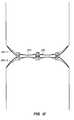
- FIGS. 2 , 4 and 6 - 10show continuous solar cell interconnects in accordance with embodiments of the present invention.
- FIG. 3shows how several solar cell interconnects may be manufactured as a stamped strip, in accordance with an embodiment of the present invention.
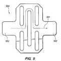
- FIG. 5shows a separate interconnect lead with strain relief features in accordance with an embodiment of the present invention.
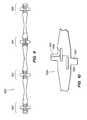
- FIG. 11shows a continuous interconnect electrically connecting adjacent back side contact solar cells, in accordance with an embodiment of the present invention.
- FIG. 12shows the interconnect arrangement of FIG. 11 with an interconnect shield, in accordance with an embodiment of the present invention.
- the present inventionrelates to interconnects for electrically connecting solar cells.
- Embodiments of the present inventionare especially beneficial for interconnecting back side contact solar cells, such as those disclosed in the following commonly-owned disclosures: U.S. patent application Ser. No. 10/633,188, filed on Aug. 1, 2003, entitled “Solar Cell Interconnect Structure” and U.S. patent application Ser. No. 11/140,460, filed on May 27, 2005, entitled “Interconnection of Solar Cells in a Solar Cell Module.”
- the just mentioned disclosuresare included in the aforementioned U.S. Provisional Application No. 60/840,166.
- a single, continuous interconnectattaches to multiple conductive areas of two adjacent solar cells (e.g., see '460 application, interconnect 210 shown in FIGS. 3( a ) and 4 ).
- the single interconnectmay have in-plane slits (e.g., see '460 application, slits 302 shown in FIGS. 3( a ) and 4 ).
- the slitsadvantageously provide strain relief, which is particularly important in solar cell applications because solar cells may have thermal expansion coefficients that differ from encapsulation materials, such as glass.
- FIG. 1shows a solar cell interconnect 100 similar to those disclosed in the '460 application.
- An in-plane slitmay be made larger to provide more strain relief.
- such a designwould also lengthen the electrical path between adjacent solar cells, resulting in increased electrical resistance and thus efficiency loss.
- Providing a straight and direct electrical path between opposing tabs of an interconnectdoes not solve the problem because such a straight path essentially eliminates the strain relief. What is needed is an interconnect design that provides more strain relief without unduly lengthening the electrical path through the interconnect.
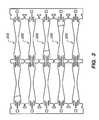
- FIG. 2shows an interconnect 200 in accordance with an embodiment of the present invention.
- the interconnect 200includes a middle portion 210 and two end portions 220 .
- Each portion of the interconnect 200has tabs for connecting to conductive pads (also referred to as “contact points” or “conductive areas”) of back side contact solar cells.
- the middle portion 210has tabs 201
- the end portions 220have tabs 202 .
- the each end portion 220may mirror half of the middle portion 210 , with appropriate adjustments in dimensions to match the dimensions of a conductive pad of a solar cell.
- the middle and end portionsmay have different geometries and/or in-plane strain relief configurations to accommodate different pad designs.
- FIG. 4shows an interconnect 400 in accordance with an embodiment of the present invention, where alternative end portions 420 are essentially the same as the middle portion 410 .
- the interconnect 400 of FIG. 4is an alternative embodiment with tapered (lobed) end portions 420 .
- the end portions 420are essentially the same as the middle portion 410 but have a tapered edge.
- the end portions 420have the same slit configuration as the middle portion 410 .
- each portion of the interconnect 200has in-plane (i.e., on the same plane as the interconnect) slits for strain relief.
- the slit in the middle rowis made longer than those in the top and bottom rows, but does not extend past the outer ends of the slits in the top and bottom rows.
- the slits in the top and bottom rowsadd strain relief, advantageously allowing the slit in the middle row to be kept relatively short compared to conventional strain relieves.
- the staggered spacing of the slitsallow electrical current to pass from the top tab 201 to the opposing bottom tab 201 between slits in the top and bottom rows and around the slit in the middle row.
- Making the slit in the middle row relatively shorthelps minimize electrical current path lengths between tabs; adding slits on the top and bottom rows helps increase strain relief to compensate for the relatively short slit in the middle row.
- this solutionadvantageously provides increased strain relief without unduly increasing electrical path resistance through the interconnect.
- FIG. 3shows how several interconnects 200 may be made as a patterned strip (e.g., comprising copper) for low-cost, automated assembly.
- the interconnects 200may be formed by stamping, chemical etching, EDM or other suitable manufacturing process without detracting from the merits of the present invention.
- FIG. 5shows an alternative embodiment where a solar cell interconnect lead 500 is a separate interconnect lead (i.e., without end portions), as in the '188 application.
- Arrow 501shows an example current path between opposing tabs 502 .
- the interconnect lead 500takes advantage of the in-plane strain relief arrangement of the continuous solar cell interconnect 200 .
- a middle or end portion of any of the continuous solar cell interconnects disclosed hereinmay be employed as a separate interconnect lead.
- a separate interconnect leadonly attaches to a single conductive pad on each of the adjacent solar cells.
- a separate interconnect lead, such as interconnect lead 500may have a single continuous tab on each end as in FIG. 5 , or two or more separate tabs on each end to meet the needs of particular applications.
- FIGS. 6-10show solar cell interconnects in alternative embodiments of the present invention. Note that the end portions of the interconnects of FIGS. 6-10 may have different slit designs than the middle portion as in the interconnect 200 of FIG. 2 , or be copied versions of the middle portion as in the interconnect 400 of FIG. 4 .
- FIG. 6shows an interconnect 600 where the middle row has two slits and the top and bottom rows each has a single slit.
- Detail A of FIG. 6shows an enlarged view of the middle portion of the interconnect 600 .
- Arrow 601shows an example current path between opposing tabs 602 .
- FIG. 7shows an interconnect 700 that is similar to the interconnect 200 of FIG. 2 except for the keyholes at the ends of the slits.
- Detail A of FIG. 7shows an enlarged view of the middle portion of the interconnect 700 .
- FIG. 8shows an interconnect 800 with more than three rows of slits. Detail A of FIG. 8 shows an enlarged view of the middle portion of the interconnect 800 .
- FIG. 9shows an interconnect 900 with more than three portions.
- FIG. 10shows an interconnect 1000 with offset tabs 1001 and two rows of offset slits 1002 .
- FIG. 11shows the continuous interconnect 200 electrically connecting adjacent back side contact solar cells 260 - 1 and 260 - 2 .
- tabs 202 and 201 of the interconnect 200electrically connect positive pads 263 of the solar cell 260 - 2 to the negative pads 262 of the solar cell 260 - 1 , on the back sides of the solar cells.
- the front side of a solar cellfaces the sun to collect solar radiation during normal operation; the back side is opposite the front side.
- FIG. 12shows the continuous interconnect 200 employed with an interconnect shield 270 , as in the '460 application. Also shown in FIG. 12 are the back side contact solar cells 260 - 1 and 260 - 2 electrically connected by the continuous interconnect 200 as in FIG. 11 .
- the interconnect shield 270may be located between the interconnect 200 and the solar cells 260 - 1 and 260 - 2 .
- the interconnect shield 270may comprise a material that provides electrical insulation and can visually block the interconnect 200 as seen from the front side of the solar cells 260 - 1 and 260 - 2 .
- the interconnect 200may be printed or chemically treated to have a color that does not detract from the aesthetics of the solar cells 260 - 1 and 260 - 2 at least as viewed from the front side.
Landscapes
- Photovoltaic Devices (AREA)
Abstract
Description
Claims (7)
Priority Applications (2)
| Application Number | Priority Date | Filing Date | Title |
|---|---|---|---|
| US11/895,640US8148627B2 (en) | 2006-08-25 | 2007-08-23 | Solar cell interconnect with multiple current paths |
| US13/414,165US9691924B1 (en) | 2006-08-25 | 2012-03-07 | Solar cell interconnect with multiple current paths |
Applications Claiming Priority (2)
| Application Number | Priority Date | Filing Date | Title |
|---|---|---|---|
| US84016606P | 2006-08-25 | 2006-08-25 | |
| US11/895,640US8148627B2 (en) | 2006-08-25 | 2007-08-23 | Solar cell interconnect with multiple current paths |
Related Child Applications (1)
| Application Number | Title | Priority Date | Filing Date |
|---|---|---|---|
| US13/414,165ContinuationUS9691924B1 (en) | 2006-08-25 | 2012-03-07 | Solar cell interconnect with multiple current paths |
Publications (2)
| Publication Number | Publication Date |
|---|---|
| US20100144218A1 US20100144218A1 (en) | 2010-06-10 |
| US8148627B2true US8148627B2 (en) | 2012-04-03 |
Family
ID=42231594
Family Applications (2)
| Application Number | Title | Priority Date | Filing Date |
|---|---|---|---|
| US11/895,640Active2029-05-28US8148627B2 (en) | 2006-08-25 | 2007-08-23 | Solar cell interconnect with multiple current paths |
| US13/414,165Active2030-03-09US9691924B1 (en) | 2006-08-25 | 2012-03-07 | Solar cell interconnect with multiple current paths |
Family Applications After (1)
| Application Number | Title | Priority Date | Filing Date |
|---|---|---|---|
| US13/414,165Active2030-03-09US9691924B1 (en) | 2006-08-25 | 2012-03-07 | Solar cell interconnect with multiple current paths |
Country Status (1)
| Country | Link |
|---|---|
| US (2) | US8148627B2 (en) |
Cited By (36)
| Publication number | Priority date | Publication date | Assignee | Title |
|---|---|---|---|---|
| US20090159116A1 (en)* | 2005-10-14 | 2009-06-25 | Yoshinobu Umetani | Interconnector, solar cell string using the interconnector and method of manufacturing thereof, and a solar cell module using the solar cell string |
| US20110132428A1 (en)* | 2006-08-31 | 2011-06-09 | Antaya Technologies Corporation | Buss Bar Strip |
| US20120100761A1 (en)* | 2009-06-08 | 2012-04-26 | Auto Kabel Managementgesellschaft Mbh | Battery Cell Connector |
| USD665339S1 (en)* | 2012-03-16 | 2012-08-14 | Emcore Solar Power, Inc. | Metal interconnecting member for solar cells |
| USD665338S1 (en)* | 2012-03-16 | 2012-08-14 | Emcore Solar Power, Inc. | Metal interconnecting member for solar cells |
| US8464496B2 (en) | 2009-03-20 | 2013-06-18 | Northern States Metals Company | Support system for solar panels |
| US8650812B2 (en) | 2009-03-20 | 2014-02-18 | Northern States Metals Company | Support system for solar panels |
| US20140073152A1 (en)* | 2012-09-07 | 2014-03-13 | Apple Inc. | Conductive connections allowing xyz translation |
| US8786095B2 (en) | 2010-09-29 | 2014-07-22 | Sunpower Corporation | Interconnect for an optoelectronic device |
| US8839573B2 (en) | 2011-02-11 | 2014-09-23 | Northern States Metals Company | Spring clip |
| US8936709B2 (en) | 2013-03-13 | 2015-01-20 | Gtat Corporation | Adaptable free-standing metallic article for semiconductors |
| US9281419B2 (en) | 2007-03-30 | 2016-03-08 | Sunpower Corporation | Localized power point optimizer for solar cell installations |
| US9303663B2 (en) | 2013-04-11 | 2016-04-05 | Northern States Metals Company | Locking rail alignment system |
| USD777659S1 (en)* | 2015-05-08 | 2017-01-31 | Solaero Technologies Corp. | Metal interconnecting member for solar cells |
| USD777660S1 (en)* | 2015-05-12 | 2017-01-31 | Solaero Technologies Corp. | Metal interconnecting member for solar cells |
| US9691924B1 (en) | 2006-08-25 | 2017-06-27 | Sunpower Corporation | Solar cell interconnect with multiple current paths |
| US20170236960A1 (en)* | 2015-08-07 | 2017-08-17 | Solaero Technologies Corp. | Reliable interconnection of solar cells |
| US9865757B2 (en) | 2014-04-23 | 2018-01-09 | Helion Concepts, Inc. | Method for quick self interconnection of photovoltaic cell arrays and panels |
| USD822890S1 (en) | 2016-09-07 | 2018-07-10 | Felxtronics Ap, Llc | Lighting apparatus |
| USD832494S1 (en) | 2017-08-09 | 2018-10-30 | Flex Ltd. | Lighting module heatsink |
| USD832495S1 (en) | 2017-08-18 | 2018-10-30 | Flex Ltd. | Lighting module locking mechanism |
| USD833061S1 (en) | 2017-08-09 | 2018-11-06 | Flex Ltd. | Lighting module locking endcap |
| USD846793S1 (en) | 2017-08-09 | 2019-04-23 | Flex Ltd. | Lighting module locking mechanism |
| USD856116S1 (en)* | 2018-03-21 | 2019-08-13 | K-International, Inc. | End cap retainer |
| USD862778S1 (en) | 2017-08-22 | 2019-10-08 | Flex Ltd | Lighting module lens |
| USD862777S1 (en) | 2017-08-09 | 2019-10-08 | Flex Ltd. | Lighting module wide distribution lens |
| USD872319S1 (en) | 2017-08-09 | 2020-01-07 | Flex Ltd. | Lighting module LED light board |
| USD877964S1 (en) | 2017-08-09 | 2020-03-10 | Flex Ltd. | Lighting module |
| USD887963S1 (en)* | 2016-01-27 | 2020-06-23 | Solaero Technologies Corp. | Flexible interconnecting member for solar cells |
| USD888323S1 (en) | 2017-09-07 | 2020-06-23 | Flex Ltd | Lighting module wire guard |
| USD888655S1 (en)* | 2016-01-26 | 2020-06-30 | Solaero Technologies Corp. | Flexible interconnecting member for solar cells |
| US10775030B2 (en) | 2017-05-05 | 2020-09-15 | Flex Ltd. | Light fixture device including rotatable light modules |
| US11025193B2 (en) | 2016-08-16 | 2021-06-01 | Helion Concepts, Inc. | Compact, low-profile, multiply configurable solar photovoltaic module with concealed connectors |
| US20230402969A1 (en)* | 2022-06-14 | 2023-12-14 | Commissariat A L'energie Atomique Et Aux Energies Alternatives | Interconnection element, photovoltaic string and associated methods |
| US11935979B2 (en) | 2017-04-24 | 2024-03-19 | Helion Concepts, Inc. | Lightweight solar panels with solar cell structural protection |
| US12125929B2 (en) | 2018-04-05 | 2024-10-22 | Maxeon Solar Pte. Ltd. | Solar device with insulated interconnectors |
Families Citing this family (25)
| Publication number | Priority date | Publication date | Assignee | Title |
|---|---|---|---|---|
| US9029689B2 (en)* | 2010-12-23 | 2015-05-12 | Sunpower Corporation | Method for connecting solar cells |
| US9153720B1 (en) | 2011-02-10 | 2015-10-06 | The Boeing Company | Electrical interconnect |
| WO2012147352A1 (en)* | 2011-04-26 | 2012-11-01 | パナソニック株式会社 | Solar battery cell, junction structure, and solar battery cell fabrication method |
| JP5927550B2 (en)* | 2011-07-29 | 2016-06-01 | パナソニックIpマネジメント株式会社 | Solar cell module |
| KR101282943B1 (en)* | 2011-09-29 | 2013-07-08 | 엘지전자 주식회사 | Solar cell module |
| JP5934978B2 (en)* | 2012-04-23 | 2016-06-15 | パナソニックIpマネジメント株式会社 | Solar cell module |
| US9306085B2 (en)* | 2012-08-22 | 2016-04-05 | Sunpower Corporation | Radially arranged metal contact fingers for solar cells |
| US20140124014A1 (en)* | 2012-11-08 | 2014-05-08 | Cogenra Solar, Inc. | High efficiency configuration for solar cell string |
| JP6213907B2 (en)* | 2012-11-30 | 2017-10-18 | パナソニックIpマネジメント株式会社 | Solar cell module |
| US20150340528A1 (en)* | 2012-12-10 | 2015-11-26 | Alliance For Sustainable Energy, Llc | Monolithic tandem voltage-matched multijuntion solar cells |
| CN103972316A (en)* | 2013-01-31 | 2014-08-06 | 江苏宇邦光伏材料有限公司 | Special shaped welding strip for back-contacting solar battery panel |
| KR102087156B1 (en)* | 2013-07-09 | 2020-03-10 | 엘지전자 주식회사 | Solar cell module |
| US10535790B2 (en) | 2015-06-25 | 2020-01-14 | Sunpower Corporation | One-dimensional metallization for solar cells |
| JP6399990B2 (en)* | 2015-09-28 | 2018-10-03 | 株式会社豊田自動織機 | Interconnector and solar panel |
| US10361322B2 (en)* | 2015-10-08 | 2019-07-23 | Lg Electronics Inc. | Solar cell module |
| JP2017175050A (en)* | 2016-03-25 | 2017-09-28 | 株式会社豊田自動織機 | Interconnector and solar panel |
| JP6509159B2 (en)* | 2016-04-28 | 2019-05-08 | 株式会社豊田自動織機 | Interconnector and solar panel |
| JP6436943B2 (en)* | 2016-08-08 | 2018-12-12 | 株式会社豊田自動織機 | Interconnector and solar panel |
| US12094991B2 (en)* | 2019-11-13 | 2024-09-17 | Maxeon Solar Pte. Ltd. | Hybrid dense solar cells and interconnects for solar modules and related methods of manufacture |
| JP7507569B2 (en)* | 2020-02-25 | 2024-06-28 | シャープ株式会社 | Interconnection sheet, solar cell with interconnection sheet, and solar cell module |
| US11165387B2 (en) | 2020-03-03 | 2021-11-02 | Sunpower Corporation | Current cyclical testing for PV electrical connections |
| US11532761B2 (en) | 2020-06-04 | 2022-12-20 | Sunpower Corporation | Composite masking between solar cells |
| JP7595750B2 (en)* | 2020-08-31 | 2024-12-06 | 泰州隆基▲樂▼叶光伏科技有限公司 | Method and apparatus for manufacturing interconnection components |
| CN112186058B (en)* | 2020-08-31 | 2025-08-19 | 泰州隆基乐叶光伏科技有限公司 | Interconnection piece and solar cell module |
| CN114203847B (en)* | 2022-02-18 | 2022-07-15 | 浙江爱旭太阳能科技有限公司 | Special-shaped welding strip for connecting back contact battery |
Citations (28)
| Publication number | Priority date | Publication date | Assignee | Title |
|---|---|---|---|---|
| US4321418A (en) | 1979-05-08 | 1982-03-23 | Saint Gobain Vitrage | Process for manufacture of solar photocell panels and panels obtained thereby |
| US4927770A (en) | 1988-11-14 | 1990-05-22 | Electric Power Research Inst. Corp. Of District Of Columbia | Method of fabricating back surface point contact solar cells |
| US5011544A (en) | 1989-09-08 | 1991-04-30 | Solarex Corporation | Solar panel with interconnects and masking structure, and method |
| US5053083A (en) | 1989-05-08 | 1991-10-01 | The Board Of Trustees Of The Leland Stanford Junior University | Bilevel contact solar cells |
| US5100808A (en) | 1990-08-15 | 1992-03-31 | Spectrolab, Inc. | Method of fabricating solar cell with integrated interconnect |
| US5164019A (en) | 1991-07-31 | 1992-11-17 | Sunpower Corporation | Monolithic series-connected solar cells having improved cell isolation and method of making same |
| US5185042A (en) | 1991-08-01 | 1993-02-09 | Trw Inc. | Generic solar cell array using a printed circuit substrate |
| US5360990A (en) | 1993-03-29 | 1994-11-01 | Sunpower Corporation | P/N junction device having porous emitter |
| US5369291A (en) | 1993-03-29 | 1994-11-29 | Sunpower Corporation | Voltage controlled thyristor |
| US5468652A (en) | 1993-07-14 | 1995-11-21 | Sandia Corporation | Method of making a back contacted solar cell |
| US5660646A (en) | 1994-11-04 | 1997-08-26 | Canon Kabushiki Kaisha | Solar battery module |
| US5972732A (en) | 1997-12-19 | 1999-10-26 | Sandia Corporation | Method of monolithic module assembly |
| US6274402B1 (en) | 1999-12-30 | 2001-08-14 | Sunpower Corporation | Method of fabricating a silicon solar cell |
| US6313395B1 (en)* | 2000-04-24 | 2001-11-06 | Sunpower Corporation | Interconnect structure for solar cells and method of making same |
| US6315575B1 (en) | 1999-03-10 | 2001-11-13 | Sharp Kabushiki Kaisha | Interconnector electrically connecting plurality of electronic device elements, fabrication method thereof, and join apparatus thereof |
| US6333457B1 (en) | 2000-08-29 | 2001-12-25 | Sunpower Corporation | Edge passivated silicon solar/photo cell and method of manufacture |
| US6337283B1 (en) | 1999-12-30 | 2002-01-08 | Sunpower Corporation | Method of fabricating a silicon solar cell |
| US6387726B1 (en) | 1999-12-30 | 2002-05-14 | Sunpower Corporation | Method of fabricating a silicon solar cell |
| US20020059952A1 (en) | 2000-11-21 | 2002-05-23 | Keiji Shimada | Solar battery module, replacement solar cell, and method of replacing solar cell |
| US6423568B1 (en) | 1999-12-30 | 2002-07-23 | Sunpower Corporation | Method of fabricating a silicon solar cell |
| US20030029036A1 (en) | 2001-08-10 | 2003-02-13 | Astrium Gmbh | Method of repairing a solar panel |
| US20030034062A1 (en)* | 2001-08-17 | 2003-02-20 | Stern Theodore Garry | Electrostatically clean solar array |
| US20040040593A1 (en) | 1998-05-28 | 2004-03-04 | Frank Ho | Solar cell having an integral monolithically grown bypass diode |
| US20050268959A1 (en)* | 2004-06-04 | 2005-12-08 | Sunpower Corporation | Interconnection of solar cells in a solar cell module |
| US20060085167A1 (en) | 2003-04-04 | 2006-04-20 | Warfield Donald B | Performance monitor for a photovoltaic supply |
| US7148774B1 (en) | 2005-07-11 | 2006-12-12 | Eaton Corporation | Contact assembly |
| US7154361B2 (en) | 2005-05-04 | 2006-12-26 | General Electric Company | Accessories for a rotatable latching shaft of a circuit breaker |
| US7161105B2 (en) | 2004-08-05 | 2007-01-09 | Siemens Aktiengesellschaft | Electrical switching device |
Family Cites Families (12)
| Publication number | Priority date | Publication date | Assignee | Title |
|---|---|---|---|---|
| US4350836A (en)* | 1980-10-14 | 1982-09-21 | The United States Of America As Represented By The United States Department Of Energy | Solar array construction |
| JP2000112545A (en) | 1998-09-30 | 2000-04-21 | Daihen Corp | Photovoltaic power generation system |
| WO2003050934A2 (en) | 2001-12-10 | 2003-06-19 | Intersil Americas Inc. | Efficient buck topology dc-dc power stage utilizing monolithic n-channel upper fet and pilot current |
| US7371963B2 (en) | 2002-07-31 | 2008-05-13 | Kyocera Corporation | Photovoltaic power generation system |
| JP2005151662A (en) | 2003-11-13 | 2005-06-09 | Sharp Corp | Inverter device and distributed power supply system |
| JP4133924B2 (en) | 2004-05-14 | 2008-08-13 | Necトーキン株式会社 | Power supply |
| US7839022B2 (en) | 2004-07-13 | 2010-11-23 | Tigo Energy, Inc. | Device for distributed maximum power tracking for solar arrays |
| TWI281305B (en) | 2005-02-03 | 2007-05-11 | Richtek Techohnology Corp | Dual input voltage converter and its control method |
| US7505833B2 (en) | 2006-03-29 | 2009-03-17 | General Electric Company | System, method, and article of manufacture for controlling operation of an electrical power generation system |
| US8148627B2 (en) | 2006-08-25 | 2012-04-03 | Sunpower Corporation | Solar cell interconnect with multiple current paths |
| US7514900B2 (en) | 2006-10-06 | 2009-04-07 | Apple Inc. | Portable devices having multiple power interfaces |
| US8158877B2 (en) | 2007-03-30 | 2012-04-17 | Sunpower Corporation | Localized power point optimizer for solar cell installations |
- 2007
- 2007-08-23USUS11/895,640patent/US8148627B2/enactiveActive
- 2012
- 2012-03-07USUS13/414,165patent/US9691924B1/enactiveActive
Patent Citations (28)
| Publication number | Priority date | Publication date | Assignee | Title |
|---|---|---|---|---|
| US4321418A (en) | 1979-05-08 | 1982-03-23 | Saint Gobain Vitrage | Process for manufacture of solar photocell panels and panels obtained thereby |
| US4927770A (en) | 1988-11-14 | 1990-05-22 | Electric Power Research Inst. Corp. Of District Of Columbia | Method of fabricating back surface point contact solar cells |
| US5053083A (en) | 1989-05-08 | 1991-10-01 | The Board Of Trustees Of The Leland Stanford Junior University | Bilevel contact solar cells |
| US5011544A (en) | 1989-09-08 | 1991-04-30 | Solarex Corporation | Solar panel with interconnects and masking structure, and method |
| US5100808A (en) | 1990-08-15 | 1992-03-31 | Spectrolab, Inc. | Method of fabricating solar cell with integrated interconnect |
| US5164019A (en) | 1991-07-31 | 1992-11-17 | Sunpower Corporation | Monolithic series-connected solar cells having improved cell isolation and method of making same |
| US5185042A (en) | 1991-08-01 | 1993-02-09 | Trw Inc. | Generic solar cell array using a printed circuit substrate |
| US5360990A (en) | 1993-03-29 | 1994-11-01 | Sunpower Corporation | P/N junction device having porous emitter |
| US5369291A (en) | 1993-03-29 | 1994-11-29 | Sunpower Corporation | Voltage controlled thyristor |
| US5468652A (en) | 1993-07-14 | 1995-11-21 | Sandia Corporation | Method of making a back contacted solar cell |
| US5660646A (en) | 1994-11-04 | 1997-08-26 | Canon Kabushiki Kaisha | Solar battery module |
| US5972732A (en) | 1997-12-19 | 1999-10-26 | Sandia Corporation | Method of monolithic module assembly |
| US20040040593A1 (en) | 1998-05-28 | 2004-03-04 | Frank Ho | Solar cell having an integral monolithically grown bypass diode |
| US6315575B1 (en) | 1999-03-10 | 2001-11-13 | Sharp Kabushiki Kaisha | Interconnector electrically connecting plurality of electronic device elements, fabrication method thereof, and join apparatus thereof |
| US6274402B1 (en) | 1999-12-30 | 2001-08-14 | Sunpower Corporation | Method of fabricating a silicon solar cell |
| US6337283B1 (en) | 1999-12-30 | 2002-01-08 | Sunpower Corporation | Method of fabricating a silicon solar cell |
| US6387726B1 (en) | 1999-12-30 | 2002-05-14 | Sunpower Corporation | Method of fabricating a silicon solar cell |
| US6423568B1 (en) | 1999-12-30 | 2002-07-23 | Sunpower Corporation | Method of fabricating a silicon solar cell |
| US6313395B1 (en)* | 2000-04-24 | 2001-11-06 | Sunpower Corporation | Interconnect structure for solar cells and method of making same |
| US6333457B1 (en) | 2000-08-29 | 2001-12-25 | Sunpower Corporation | Edge passivated silicon solar/photo cell and method of manufacture |
| US20020059952A1 (en) | 2000-11-21 | 2002-05-23 | Keiji Shimada | Solar battery module, replacement solar cell, and method of replacing solar cell |
| US20030029036A1 (en) | 2001-08-10 | 2003-02-13 | Astrium Gmbh | Method of repairing a solar panel |
| US20030034062A1 (en)* | 2001-08-17 | 2003-02-20 | Stern Theodore Garry | Electrostatically clean solar array |
| US20060085167A1 (en) | 2003-04-04 | 2006-04-20 | Warfield Donald B | Performance monitor for a photovoltaic supply |
| US20050268959A1 (en)* | 2004-06-04 | 2005-12-08 | Sunpower Corporation | Interconnection of solar cells in a solar cell module |
| US7161105B2 (en) | 2004-08-05 | 2007-01-09 | Siemens Aktiengesellschaft | Electrical switching device |
| US7154361B2 (en) | 2005-05-04 | 2006-12-26 | General Electric Company | Accessories for a rotatable latching shaft of a circuit breaker |
| US7148774B1 (en) | 2005-07-11 | 2006-12-12 | Eaton Corporation | Contact assembly |
Non-Patent Citations (26)
| Title |
|---|
| "Flipper Turbot Build Sheet", [retrieved on Apr. 25, 2007], 4 pages, Retrieved from the internet website ., illustrating work completed in Oct. 2003. |
| "Flipper Turbot Build Sheet", [retrieved on Apr. 25, 2007], 4 pages, Retrieved from the internet website <http://www.jwgoerlich.solarbnotics/flipper/build—sheet.htm>., illustrating work completed in Oct. 2003. |
| "Flipper" [retrieved on Apr. 25, 2007], 1 pg., Retrieved from the internet website ., illustrating work completed in Oct. 2003. |
| "Flipper" [retrieved on Apr. 25, 2007], 1 pg., Retrieved from the internet website <http://jwgoerlich.solarbotics.net/robots/flipper/default.htm>., illustrating work completed in Oct. 2003. |
| Akira Terao, et al., "A Mirror-Less Design for Micro-Concentrator Modules", 2000, 4 sheets; Proceedings of the 28th IEEE PVSC. |
| Archive.org website, "CSE Distributors PVC Tape", retieved on Apr. 25, 2007, 2 pages, [Retrieved from the internet: . |
| Archive.org website, "CSE Distributors PVC Tape", retieved on Apr. 25, 2007, 2 pages, [Retrieved from the internet: <http://www.csedistributors.com/acatalog/PVC—Tape.html>. |
| Archive.org website, "The Glue Store-Adhesives 101", retrieved on Apr. 27, 2007, 6 pages, [Retrieved from the internet: . |
| Archive.org website, "The Glue Store—Adhesives 101", retrieved on Apr. 27, 2007, 6 pages, [Retrieved from the internet: <http://www.glue-store.com/adhesives101.html>. |
| C.W. Paul, "Hot-Melt Adhesives", MRS Bulletin, Jun. 2003, pp. 440-444. |
| D.M.Considine, Ed., "Van Nostrand's Scientific Encyclopedia", New York: Van Nostrand Reinhold, 1989, p. 1096. |
| DSP56F80x in Power Line Modem Applications, 6 sheets, 2004-2006 Freescale Semiconductor, Inc., webpage [online] [retrieved on Nov. 20, 2006]. Retrieved from the internet: http://www.freescale.com/webapp/sps/site/application.jsp?nodeid=023Z1Dj0Tcf5hr. |
| E-T-A Circuit Breakers, E-1048-800 Smart Circuit Breaker, "E-T-A Announces Remote Power Controller utilizing Smart Circuit Breaker Technology", Feb. 23, 2004, 3 sheets, The National Design Engineering Show, Chicago, U.S.A. |
| Keith R. McIntosh, et al., "The Choice of Silicon Wafer for the Production of Low-Cost Rear-Contact Solar Cells", May 2003, 4 sheets; Sunnyvale, California. |
| OFDM Power Line Modem-Block Diagram, 2 sheets, 1995-2006 Texas Instruments Incorporated, webpage [online] [retrieved on Nov. 20, 2006]. Retrieved from the internet: http://focus.ti.com/vf/docs/blockdiagram.tsp?family=vf&blockDiagramId=6054. |
| P.J. Verlinden, et al., "Backside-Contact Silicon Solar Cells with Improved Efficiency for the '96 World Solar Challenge", 1997, 5 sheets; Proceedings of the 15th EPSEC. |
| P.J. Verlinden, et al., "One-Year Comparison of a Concentrator Module with Silicon Point-Contact Solar Cell to a Fixed Flat Plate Module in Nothern California", 2000, 4 sheets; Proceedings of the 16th EPSEC. |
| P.J. Verlinden, et al., "Will We Have a 20%-Efficient (PTC) Photovoltaic System?", 2001, 6 sheets; Proceedings of the 17th Europe Photovoltaic Solar Energy Conference. |
| Richard A. Cullen, "Maximum Power Point Tracking", pp. 1-5, [retrieved on Feb. 24, 2007] [Retrieved from the internet: <http://www.earthtoys.com/emagazine.php?issue-number=03.02.01&article=power-point-tracking>. |
| Richard M. Swanson, "The Promise of Concentrators", 2000, pp. 93-111, Progress in Photovoltaics: Research and Applications. |
| Trishan Esram and Patrick L. Chapman, "Comparison of Photovoltaic Array Maximum Power Point Tracking Techniques", 11 sheets, [retrieved on Feb. 28, 2007] [Retrieved from the internet: . |
| Trishan Esram and Patrick L. Chapman, "Comparison of Photovoltaic Array Maximum Power Point Tracking Techniques", 11 sheets, [retrieved on Feb. 28, 2007] [Retrieved from the internet: <http://energy.ece.uiuc.edu/chapman/papers/EC%202006%20in%20press.pdf>. |
| W.P. Mulligan, et al., "A Flat-Plate Concentrator: Micro-Concentrator Design Overview", 2000, 3 sheets; Proceedings of the 28th IEEE PVSC. |
| William P. Mulligan, et al., "Development of Chip-Size Silicon Solar Cells", 2000, 6 sheets; Proceedings of the 28th IEEE PVSC. |
| Wind&Sun Electricity From The Sun, Maximum Power Point Tracking, pp. 1-7, [retrieved on Feb. 24, 2007] [Retrieved from the internet: . |
| Wind&Sun Electricity From The Sun, Maximum Power Point Tracking, pp. 1-7, [retrieved on Feb. 24, 2007] [Retrieved from the internet: <http://www.wind-sun.com/Charge—Controls—Meters/PPT.htm>. |
Cited By (53)
| Publication number | Priority date | Publication date | Assignee | Title |
|---|---|---|---|---|
| US20090159116A1 (en)* | 2005-10-14 | 2009-06-25 | Yoshinobu Umetani | Interconnector, solar cell string using the interconnector and method of manufacturing thereof, and a solar cell module using the solar cell string |
| US9691924B1 (en) | 2006-08-25 | 2017-06-27 | Sunpower Corporation | Solar cell interconnect with multiple current paths |
| US9012776B2 (en) | 2006-08-31 | 2015-04-21 | Antaya Technologies Corporation | Buss bar strip |
| US20110132428A1 (en)* | 2006-08-31 | 2011-06-09 | Antaya Technologies Corporation | Buss Bar Strip |
| US8222523B2 (en)* | 2006-08-31 | 2012-07-17 | Antaya Technologies Corporation | Buss bar strip |
| US9368651B2 (en) | 2006-08-31 | 2016-06-14 | Antaya Technologies Corporation | Buss bar strip |
| US8779291B2 (en) | 2006-08-31 | 2014-07-15 | Antaya Technologies Corporation | Buss bar strip |
| US9281419B2 (en) | 2007-03-30 | 2016-03-08 | Sunpower Corporation | Localized power point optimizer for solar cell installations |
| US8650812B2 (en) | 2009-03-20 | 2014-02-18 | Northern States Metals Company | Support system for solar panels |
| US8464496B2 (en) | 2009-03-20 | 2013-06-18 | Northern States Metals Company | Support system for solar panels |
| US8574008B2 (en)* | 2009-06-08 | 2013-11-05 | Bayerische Motoren Werke | Battery cell connector |
| US20120100761A1 (en)* | 2009-06-08 | 2012-04-26 | Auto Kabel Managementgesellschaft Mbh | Battery Cell Connector |
| US9537036B2 (en)* | 2010-09-29 | 2017-01-03 | Sunpower Corporation | Interconnect for an optoelectronic device |
| US8786095B2 (en) | 2010-09-29 | 2014-07-22 | Sunpower Corporation | Interconnect for an optoelectronic device |
| US20140291852A1 (en)* | 2010-09-29 | 2014-10-02 | Ryan Linderman | Interconnect for an optoelectronic device |
| US8839573B2 (en) | 2011-02-11 | 2014-09-23 | Northern States Metals Company | Spring clip |
| USD665338S1 (en)* | 2012-03-16 | 2012-08-14 | Emcore Solar Power, Inc. | Metal interconnecting member for solar cells |
| USD665339S1 (en)* | 2012-03-16 | 2012-08-14 | Emcore Solar Power, Inc. | Metal interconnecting member for solar cells |
| US8895865B2 (en)* | 2012-09-07 | 2014-11-25 | Conor P. Lenahan | Conductive connections allowing XYZ translation |
| US20140073152A1 (en)* | 2012-09-07 | 2014-03-13 | Apple Inc. | Conductive connections allowing xyz translation |
| US8936709B2 (en) | 2013-03-13 | 2015-01-20 | Gtat Corporation | Adaptable free-standing metallic article for semiconductors |
| US9303663B2 (en) | 2013-04-11 | 2016-04-05 | Northern States Metals Company | Locking rail alignment system |
| US9865757B2 (en) | 2014-04-23 | 2018-01-09 | Helion Concepts, Inc. | Method for quick self interconnection of photovoltaic cell arrays and panels |
| USD816602S1 (en)* | 2015-05-08 | 2018-05-01 | Solaero Technologies Corp. | Metal interconnecting member for solar cells |
| USD777659S1 (en)* | 2015-05-08 | 2017-01-31 | Solaero Technologies Corp. | Metal interconnecting member for solar cells |
| USD777660S1 (en)* | 2015-05-12 | 2017-01-31 | Solaero Technologies Corp. | Metal interconnecting member for solar cells |
| US10658533B2 (en)* | 2015-08-07 | 2020-05-19 | Solaero Technologies Corp. | Reliable interconnection of solar cells |
| US20170236960A1 (en)* | 2015-08-07 | 2017-08-17 | Solaero Technologies Corp. | Reliable interconnection of solar cells |
| USD888655S1 (en)* | 2016-01-26 | 2020-06-30 | Solaero Technologies Corp. | Flexible interconnecting member for solar cells |
| USD887963S1 (en)* | 2016-01-27 | 2020-06-23 | Solaero Technologies Corp. | Flexible interconnecting member for solar cells |
| US11025193B2 (en) | 2016-08-16 | 2021-06-01 | Helion Concepts, Inc. | Compact, low-profile, multiply configurable solar photovoltaic module with concealed connectors |
| USD822890S1 (en) | 2016-09-07 | 2018-07-10 | Felxtronics Ap, Llc | Lighting apparatus |
| US11935979B2 (en) | 2017-04-24 | 2024-03-19 | Helion Concepts, Inc. | Lightweight solar panels with solar cell structural protection |
| US10775030B2 (en) | 2017-05-05 | 2020-09-15 | Flex Ltd. | Light fixture device including rotatable light modules |
| USD846793S1 (en) | 2017-08-09 | 2019-04-23 | Flex Ltd. | Lighting module locking mechanism |
| USD905325S1 (en) | 2017-08-09 | 2020-12-15 | Flex Ltd | Lighting module |
| USD832494S1 (en) | 2017-08-09 | 2018-10-30 | Flex Ltd. | Lighting module heatsink |
| USD1010915S1 (en) | 2017-08-09 | 2024-01-09 | Linmore Labs Led, Inc. | Lighting module |
| USD862777S1 (en) | 2017-08-09 | 2019-10-08 | Flex Ltd. | Lighting module wide distribution lens |
| USD872319S1 (en) | 2017-08-09 | 2020-01-07 | Flex Ltd. | Lighting module LED light board |
| USD877964S1 (en) | 2017-08-09 | 2020-03-10 | Flex Ltd. | Lighting module |
| USD853627S1 (en) | 2017-08-09 | 2019-07-09 | Flex Ltd | Lighting module locking endcap |
| USD885615S1 (en) | 2017-08-09 | 2020-05-26 | Flex Ltd. | Lighting module LED light board |
| USD853625S1 (en) | 2017-08-09 | 2019-07-09 | Flex Ltd | Lighting module heatsink |
| USD833061S1 (en) | 2017-08-09 | 2018-11-06 | Flex Ltd. | Lighting module locking endcap |
| USD853629S1 (en) | 2017-08-09 | 2019-07-09 | Flex Ltd | Lighting module locking mechanism |
| USD853628S1 (en) | 2017-08-18 | 2019-07-09 | Flex Ltd. | Lighting module locking mechanism |
| USD832495S1 (en) | 2017-08-18 | 2018-10-30 | Flex Ltd. | Lighting module locking mechanism |
| USD862778S1 (en) | 2017-08-22 | 2019-10-08 | Flex Ltd | Lighting module lens |
| USD888323S1 (en) | 2017-09-07 | 2020-06-23 | Flex Ltd | Lighting module wire guard |
| USD856116S1 (en)* | 2018-03-21 | 2019-08-13 | K-International, Inc. | End cap retainer |
| US12125929B2 (en) | 2018-04-05 | 2024-10-22 | Maxeon Solar Pte. Ltd. | Solar device with insulated interconnectors |
| US20230402969A1 (en)* | 2022-06-14 | 2023-12-14 | Commissariat A L'energie Atomique Et Aux Energies Alternatives | Interconnection element, photovoltaic string and associated methods |
Also Published As
| Publication number | Publication date |
|---|---|
| US20100144218A1 (en) | 2010-06-10 |
| US9691924B1 (en) | 2017-06-27 |
Similar Documents
| Publication | Publication Date | Title |
|---|---|---|
| US8148627B2 (en) | Solar cell interconnect with multiple current paths | |
| EP2220691B1 (en) | Busbar connection configuration to accommodate for cell misalignment | |
| JP5164202B2 (en) | Interconnection of solar cells in solar cell modules | |
| US11862745B2 (en) | One-dimensional metallization for solar cells | |
| US5164019A (en) | Monolithic series-connected solar cells having improved cell isolation and method of making same | |
| US6784358B2 (en) | Solar cell structure utilizing an amorphous silicon discrete by-pass diode | |
| EP3096354B1 (en) | Solar cell contact fingers and solder pad arrangement for enhanced efficiency | |
| US7498508B2 (en) | High voltage solar cell and solar cell module | |
| JP5149376B2 (en) | Solar cell element and solar cell module | |
| US20160163902A1 (en) | Solar module having shingled solar cells | |
| WO2007043428A1 (en) | Solar cell, solar cell provided with interconnector, solar cell string and solar cell module | |
| AU2022429460A1 (en) | Solar module | |
| US20210313479A1 (en) | High Power Density Solar Module and Methods of Fabrication | |
| KR101714778B1 (en) | Solar cell module | |
| US20240363780A1 (en) | Solar module with optimized interconnection and method of manufacturing the same | |
| US12414383B2 (en) | Thin film photo-voltaic module | |
| WO2023052016A1 (en) | Solar cell module | |
| US12396271B2 (en) | Ribbons for use in shingled solar cells | |
| KR101806986B1 (en) | Solar cell module | |
| KR20150083745A (en) | Interconnector for solar cell module | |
| WO2024101216A1 (en) | Solar battery cell and solar battery module | |
| KR101816183B1 (en) | Solar cell module | |
| JP2002094102A (en) | Double-sided junction type solar cell interconnector, solar cell using the interconnector, and method of connecting the same | |
| CN120322058A (en) | Back-contact solar cells, photovoltaic modules and photovoltaic systems | |
| KR101760009B1 (en) | Solar cell module |
Legal Events
| Date | Code | Title | Description |
|---|---|---|---|
| AS | Assignment | Owner name:SUNPOWER CORPORATION,CALIFORNIA Free format text:ASSIGNMENT OF ASSIGNORS INTEREST;ASSIGNORS:ROSE, DOUGLAS H.;DAROCZI, SHANDOR G.;KAMINAR, NEIL;SIGNING DATES FROM 20070912 TO 20070927;REEL/FRAME:019957/0045 Owner name:SUNPOWER CORPORATION, CALIFORNIA Free format text:ASSIGNMENT OF ASSIGNORS INTEREST;ASSIGNORS:ROSE, DOUGLAS H.;DAROCZI, SHANDOR G.;KAMINAR, NEIL;SIGNING DATES FROM 20070912 TO 20070927;REEL/FRAME:019957/0045 | |
| STCF | Information on status: patent grant | Free format text:PATENTED CASE | |
| FPAY | Fee payment | Year of fee payment:4 | |
| AS | Assignment | Owner name:UNITED STATES DEPARTMENT OF ENERGY, DISTRICT OF CO Free format text:CONFIRMATORY LICENSE;ASSIGNOR:SUNPOWER CORPORATION;REEL/FRAME:044873/0194 Effective date:20180104 | |
| MAFP | Maintenance fee payment | Free format text:PAYMENT OF MAINTENANCE FEE, 8TH YEAR, LARGE ENTITY (ORIGINAL EVENT CODE: M1552); ENTITY STATUS OF PATENT OWNER: LARGE ENTITY Year of fee payment:8 | |
| AS | Assignment | Owner name:MAXEON SOLAR PTE. LTD., SINGAPORE Free format text:ASSIGNMENT OF ASSIGNORS INTEREST;ASSIGNOR:SUNPOWER CORPORATION;REEL/FRAME:062490/0742 Effective date:20221214 | |
| MAFP | Maintenance fee payment | Free format text:PAYMENT OF MAINTENANCE FEE, 12TH YEAR, LARGE ENTITY (ORIGINAL EVENT CODE: M1553); ENTITY STATUS OF PATENT OWNER: LARGE ENTITY Year of fee payment:12 | |
| AS | Assignment | Owner name:DB TRUSTEES (HONG KONG) LIMITED, HONG KONG Free format text:SECURITY INTEREST;ASSIGNOR:MAXEON SOLAR PTE. LTD.;REEL/FRAME:067637/0598 Effective date:20240531 | |
| AS | Assignment | Owner name:DB TRUSTEES (HONG KONG) LIMITED, HONG KONG Free format text:SECOND LIEN SECURITY INTEREST AGREEMENT;ASSIGNOR:MAXEON SOLAR PTE. LTD;REEL/FRAME:071343/0553 Effective date:20240620 | |
| AS | Assignment | Owner name:DB TRUSTEES (HONG KONG) LIMITED, HONG KONG Free format text:SECURITY INTEREST;ASSIGNOR:MAXEON SOLAR PTE. LTD.;REEL/FRAME:067924/0062 Effective date:20240620 |