US8148116B2 - Sample processing device for pretreatment and thermal cycling - Google Patents
Sample processing device for pretreatment and thermal cyclingDownload PDFInfo
- Publication number
- US8148116B2 US8148116B2US13/099,317US201113099317AUS8148116B2US 8148116 B2US8148116 B2US 8148116B2US 201113099317 AUS201113099317 AUS 201113099317AUS 8148116 B2US8148116 B2US 8148116B2
- Authority
- US
- United States
- Prior art keywords
- sample
- vessel
- sample vessel
- processing station
- processing
- Prior art date
- Legal status (The legal status is an assumption and is not a legal conclusion. Google has not performed a legal analysis and makes no representation as to the accuracy of the status listed.)
- Expired - Fee Related
Links
- 238000012545processingMethods0.000titleclaimsdescription316
- 238000005382thermal cyclingMethods0.000titleclaimsdescription46
- 230000006835compressionEffects0.000claimsdescription118
- 238000007906compressionMethods0.000claimsdescription118
- 238000006243chemical reactionMethods0.000claimsdescription73
- 239000003153chemical reaction reagentSubstances0.000claimsdescription64
- 108020004707nucleic acidsProteins0.000claimsdescription52
- 102000039446nucleic acidsHuman genes0.000claimsdescription52
- 150000007523nucleic acidsChemical class0.000claimsdescription52
- 238000012546transferMethods0.000claimsdescription47
- 238000000034methodMethods0.000claimsdescription38
- 238000001514detection methodMethods0.000claimsdescription18
- 238000000137annealingMethods0.000claimsdescription15
- 239000012530fluidSubstances0.000claimsdescription9
- 238000010438heat treatmentMethods0.000claimsdescription7
- 238000000605extractionMethods0.000claimsdescription5
- ZHNUHDYFZUAESO-UHFFFAOYSA-NFormamideChemical compoundNC=OZHNUHDYFZUAESO-UHFFFAOYSA-N0.000claimsdescription4
- 239000000126substanceSubstances0.000claimsdescription4
- 239000012807PCR reagentSubstances0.000claimsdescription3
- 230000001413cellular effectEffects0.000claimsdescription3
- 238000001668nucleic acid synthesisMethods0.000claimsdescription3
- 238000009835boilingMethods0.000claimsdescription2
- 230000006037cell lysisEffects0.000claimsdescription2
- 238000005063solubilizationMethods0.000claimsdescription2
- 230000007928solubilizationEffects0.000claimsdescription2
- 239000000284extractSubstances0.000claims1
- ZJYYHGLJYGJLLN-UHFFFAOYSA-Nguanidinium thiocyanateChemical compoundSC#N.NC(N)=NZJYYHGLJYGJLLN-UHFFFAOYSA-N0.000claims1
- 239000000523sampleSubstances0.000description617
- 239000012212insulatorSubstances0.000description44
- 238000004458analytical methodMethods0.000description23
- 238000003752polymerase chain reactionMethods0.000description21
- 239000000463materialSubstances0.000description19
- 230000033001locomotionEffects0.000description13
- 238000012360testing methodMethods0.000description13
- 239000000499gelSubstances0.000description10
- 230000003287optical effectEffects0.000description10
- 230000008569processEffects0.000description10
- 238000007789sealingMethods0.000description10
- 239000000047productSubstances0.000description9
- 238000003860storageMethods0.000description9
- 238000001816coolingMethods0.000description8
- 238000002347injectionMethods0.000description8
- 239000007924injectionSubstances0.000description8
- 238000003199nucleic acid amplification methodMethods0.000description8
- 230000003321amplificationEffects0.000description7
- 238000010276constructionMethods0.000description7
- -1e.g.Substances0.000description7
- 238000001962electrophoresisMethods0.000description7
- 230000005284excitationEffects0.000description7
- 238000005070samplingMethods0.000description7
- 238000004891communicationMethods0.000description6
- 238000001502gel electrophoresisMethods0.000description6
- 238000011068loading methodMethods0.000description6
- 230000007246mechanismEffects0.000description6
- 239000007850fluorescent dyeSubstances0.000description5
- 229920003023plasticPolymers0.000description5
- 239000004033plasticSubstances0.000description5
- 239000004698PolyethyleneSubstances0.000description4
- 238000003556assayMethods0.000description4
- 239000012472biological sampleSubstances0.000description4
- 238000010586diagramMethods0.000description4
- 239000000975dyeSubstances0.000description4
- 230000000694effectsEffects0.000description4
- 239000012528membraneSubstances0.000description4
- 239000000203mixtureSubstances0.000description4
- 229920000573polyethylenePolymers0.000description4
- 229920002635polyurethanePolymers0.000description4
- 239000004814polyurethaneSubstances0.000description4
- 238000001228spectrumMethods0.000description4
- 210000005239tubuleAnatomy0.000description4
- 108020004414DNAProteins0.000description3
- 238000000018DNA microarrayMethods0.000description3
- 239000008280bloodSubstances0.000description3
- 210000004369bloodAnatomy0.000description3
- 238000011109contaminationMethods0.000description3
- 238000002405diagnostic procedureMethods0.000description3
- 230000002068genetic effectEffects0.000description3
- 238000011534incubationMethods0.000description3
- 239000002184metalSubstances0.000description3
- 229910052751metalInorganic materials0.000description3
- 238000012544monitoring processMethods0.000description3
- 239000011541reaction mixtureSubstances0.000description3
- 238000011160researchMethods0.000description3
- IJGRMHOSHXDMSA-UHFFFAOYSA-NAtomic nitrogenChemical compoundN#NIJGRMHOSHXDMSA-UHFFFAOYSA-N0.000description2
- 102000004190EnzymesHuman genes0.000description2
- 108090000790EnzymesProteins0.000description2
- 229920000784NomexPolymers0.000description2
- 108091034117OligonucleotideProteins0.000description2
- 238000012408PCR amplificationMethods0.000description2
- 238000010521absorption reactionMethods0.000description2
- 230000004075alterationEffects0.000description2
- 230000008901benefitEffects0.000description2
- 239000000090biomarkerSubstances0.000description2
- 230000007423decreaseEffects0.000description2
- 230000001419dependent effectEffects0.000description2
- 238000013461designMethods0.000description2
- 238000002866fluorescence resonance energy transferMethods0.000description2
- 239000000383hazardous chemicalSubstances0.000description2
- 238000007834ligase chain reactionMethods0.000description2
- 239000010445micaSubstances0.000description2
- 229910052618mica groupInorganic materials0.000description2
- 238000002493microarrayMethods0.000description2
- 239000004763nomexSubstances0.000description2
- 239000002773nucleotideSubstances0.000description2
- 125000003729nucleotide groupChemical group0.000description2
- 229920003223poly(pyromellitimide-1,4-diphenyl ether)Polymers0.000description2
- 238000002360preparation methodMethods0.000description2
- 238000003672processing methodMethods0.000description2
- 210000003296salivaAnatomy0.000description2
- 229920002379silicone rubberPolymers0.000description2
- 239000004945silicone rubberSubstances0.000description2
- 230000001225therapeutic effectEffects0.000description2
- 238000011282treatmentMethods0.000description2
- 210000002700urineAnatomy0.000description2
- 229920000936AgarosePolymers0.000description1
- 102000053602DNAHuman genes0.000description1
- 102000016928DNA-directed DNA polymeraseHuman genes0.000description1
- 108010014303DNA-directed DNA polymeraseProteins0.000description1
- 238000010222PCR analysisMethods0.000description1
- FAPWRFPIFSIZLT-UHFFFAOYSA-MSodium chlorideChemical compound[Na+].[Cl-]FAPWRFPIFSIZLT-UHFFFAOYSA-M0.000description1
- JLCPHMBAVCMARE-UHFFFAOYSA-N[3-[[3-[[3-[[3-[[3-[[3-[[3-[[3-[[3-[[3-[[3-[[5-(2-amino-6-oxo-1H-purin-9-yl)-3-[[3-[[3-[[3-[[3-[[3-[[5-(2-amino-6-oxo-1H-purin-9-yl)-3-[[5-(2-amino-6-oxo-1H-purin-9-yl)-3-hydroxyoxolan-2-yl]methoxy-hydroxyphosphoryl]oxyoxolan-2-yl]methoxy-hydroxyphosphoryl]oxy-5-(5-methyl-2,4-dioxopyrimidin-1-yl)oxolan-2-yl]methoxy-hydroxyphosphoryl]oxy-5-(6-aminopurin-9-yl)oxolan-2-yl]methoxy-hydroxyphosphoryl]oxy-5-(6-aminopurin-9-yl)oxolan-2-yl]methoxy-hydroxyphosphoryl]oxy-5-(6-aminopurin-9-yl)oxolan-2-yl]methoxy-hydroxyphosphoryl]oxy-5-(6-aminopurin-9-yl)oxolan-2-yl]methoxy-hydroxyphosphoryl]oxyoxolan-2-yl]methoxy-hydroxyphosphoryl]oxy-5-(5-methyl-2,4-dioxopyrimidin-1-yl)oxolan-2-yl]methoxy-hydroxyphosphoryl]oxy-5-(4-amino-2-oxopyrimidin-1-yl)oxolan-2-yl]methoxy-hydroxyphosphoryl]oxy-5-(5-methyl-2,4-dioxopyrimidin-1-yl)oxolan-2-yl]methoxy-hydroxyphosphoryl]oxy-5-(5-methyl-2,4-dioxopyrimidin-1-yl)oxolan-2-yl]methoxy-hydroxyphosphoryl]oxy-5-(6-aminopurin-9-yl)oxolan-2-yl]methoxy-hydroxyphosphoryl]oxy-5-(6-aminopurin-9-yl)oxolan-2-yl]methoxy-hydroxyphosphoryl]oxy-5-(4-amino-2-oxopyrimidin-1-yl)oxolan-2-yl]methoxy-hydroxyphosphoryl]oxy-5-(4-amino-2-oxopyrimidin-1-yl)oxolan-2-yl]methoxy-hydroxyphosphoryl]oxy-5-(4-amino-2-oxopyrimidin-1-yl)oxolan-2-yl]methoxy-hydroxyphosphoryl]oxy-5-(6-aminopurin-9-yl)oxolan-2-yl]methoxy-hydroxyphosphoryl]oxy-5-(4-amino-2-oxopyrimidin-1-yl)oxolan-2-yl]methyl [5-(6-aminopurin-9-yl)-2-(hydroxymethyl)oxolan-3-yl] hydrogen phosphatePolymersCc1cn(C2CC(OP(O)(=O)OCC3OC(CC3OP(O)(=O)OCC3OC(CC3O)n3cnc4c3nc(N)[nH]c4=O)n3cnc4c3nc(N)[nH]c4=O)C(COP(O)(=O)OC3CC(OC3COP(O)(=O)OC3CC(OC3COP(O)(=O)OC3CC(OC3COP(O)(=O)OC3CC(OC3COP(O)(=O)OC3CC(OC3COP(O)(=O)OC3CC(OC3COP(O)(=O)OC3CC(OC3COP(O)(=O)OC3CC(OC3COP(O)(=O)OC3CC(OC3COP(O)(=O)OC3CC(OC3COP(O)(=O)OC3CC(OC3COP(O)(=O)OC3CC(OC3COP(O)(=O)OC3CC(OC3COP(O)(=O)OC3CC(OC3COP(O)(=O)OC3CC(OC3COP(O)(=O)OC3CC(OC3COP(O)(=O)OC3CC(OC3CO)n3cnc4c(N)ncnc34)n3ccc(N)nc3=O)n3cnc4c(N)ncnc34)n3ccc(N)nc3=O)n3ccc(N)nc3=O)n3ccc(N)nc3=O)n3cnc4c(N)ncnc34)n3cnc4c(N)ncnc34)n3cc(C)c(=O)[nH]c3=O)n3cc(C)c(=O)[nH]c3=O)n3ccc(N)nc3=O)n3cc(C)c(=O)[nH]c3=O)n3cnc4c3nc(N)[nH]c4=O)n3cnc4c(N)ncnc34)n3cnc4c(N)ncnc34)n3cnc4c(N)ncnc34)n3cnc4c(N)ncnc34)O2)c(=O)[nH]c1=OJLCPHMBAVCMARE-UHFFFAOYSA-N0.000description1
- 239000012190activatorSubstances0.000description1
- 239000000853adhesiveSubstances0.000description1
- 230000001070adhesive effectEffects0.000description1
- 239000003570airSubstances0.000description1
- 229910052782aluminiumInorganic materials0.000description1
- XAGFODPZIPBFFR-UHFFFAOYSA-NaluminiumChemical compound[Al]XAGFODPZIPBFFR-UHFFFAOYSA-N0.000description1
- 239000012491analyteSubstances0.000description1
- 239000003146anticoagulant agentSubstances0.000description1
- 229940127219anticoagulant drugDrugs0.000description1
- 239000000427antigenSubstances0.000description1
- 102000036639antigensHuman genes0.000description1
- 108091007433antigensProteins0.000description1
- 238000013459approachMethods0.000description1
- 239000011324beadSubstances0.000description1
- 230000005540biological transmissionEffects0.000description1
- 238000005251capillar electrophoresisMethods0.000description1
- 239000006285cell suspensionSubstances0.000description1
- 239000000919ceramicSubstances0.000description1
- 239000007795chemical reaction productSubstances0.000description1
- 238000003759clinical diagnosisMethods0.000description1
- 230000000295complement effectEffects0.000description1
- 150000001875compoundsChemical class0.000description1
- 230000003247decreasing effectEffects0.000description1
- 238000011161developmentMethods0.000description1
- 238000003745diagnosisMethods0.000description1
- 238000006073displacement reactionMethods0.000description1
- 230000009977dual effectEffects0.000description1
- 229920001971elastomerPolymers0.000description1
- 238000005265energy consumptionMethods0.000description1
- ZMMJGEGLRURXTF-UHFFFAOYSA-Nethidium bromideChemical compound[Br-].C12=CC(N)=CC=C2C2=CC=C(N)C=C2[N+](CC)=C1C1=CC=CC=C1ZMMJGEGLRURXTF-UHFFFAOYSA-N0.000description1
- 229960005542ethidium bromideDrugs0.000description1
- 239000011888foilSubstances0.000description1
- 230000006870functionEffects0.000description1
- 229920001903high density polyethylenePolymers0.000description1
- 238000013537high throughput screeningMethods0.000description1
- 239000004700high-density polyethyleneSubstances0.000description1
- 238000009396hybridizationMethods0.000description1
- 238000005286illuminationMethods0.000description1
- 238000009830intercalationMethods0.000description1
- 238000012423maintenanceMethods0.000description1
- 239000003550markerSubstances0.000description1
- 230000001404mediated effectEffects0.000description1
- 238000010339medical testMethods0.000description1
- 238000002156mixingMethods0.000description1
- 239000003068molecular probeSubstances0.000description1
- 239000002547new drugSubstances0.000description1
- 229910052757nitrogenInorganic materials0.000description1
- 230000035699permeabilityEffects0.000description1
- 229920002401polyacrylamidePolymers0.000description1
- 238000010791quenchingMethods0.000description1
- 230000000171quenching effectEffects0.000description1
- 238000003753real-time PCRMethods0.000description1
- 238000011897real-time detectionMethods0.000description1
- 238000005057refrigerationMethods0.000description1
- 230000004044responseEffects0.000description1
- 238000005096rolling processMethods0.000description1
- 238000012216screeningMethods0.000description1
- 238000004513sizingMethods0.000description1
- 239000011780sodium chlorideSubstances0.000description1
- 239000002689soilSubstances0.000description1
- 238000002076thermal analysis methodMethods0.000description1
- 238000012549trainingMethods0.000description1
- 238000013518transcriptionMethods0.000description1
- 230000035897transcriptionEffects0.000description1
- 230000007704transitionEffects0.000description1
- XLYOFNOQVPJJNP-UHFFFAOYSA-NwaterSubstancesOXLYOFNOQVPJJNP-UHFFFAOYSA-N0.000description1
Images


Classifications
- B—PERFORMING OPERATIONS; TRANSPORTING
- B01—PHYSICAL OR CHEMICAL PROCESSES OR APPARATUS IN GENERAL
- B01L—CHEMICAL OR PHYSICAL LABORATORY APPARATUS FOR GENERAL USE
- B01L7/00—Heating or cooling apparatus; Heat insulating devices
- B01L7/52—Heating or cooling apparatus; Heat insulating devices with provision for submitting samples to a predetermined sequence of different temperatures, e.g. for treating nucleic acid samples
- B—PERFORMING OPERATIONS; TRANSPORTING
- B01—PHYSICAL OR CHEMICAL PROCESSES OR APPARATUS IN GENERAL
- B01L—CHEMICAL OR PHYSICAL LABORATORY APPARATUS FOR GENERAL USE
- B01L3/00—Containers or dishes for laboratory use, e.g. laboratory glassware; Droppers
- B01L3/50—Containers for the purpose of retaining a material to be analysed, e.g. test tubes
- B01L3/502—Containers for the purpose of retaining a material to be analysed, e.g. test tubes with fluid transport, e.g. in multi-compartment structures
- B01L3/5027—Containers for the purpose of retaining a material to be analysed, e.g. test tubes with fluid transport, e.g. in multi-compartment structures by integrated microfluidic structures, i.e. dimensions of channels and chambers are such that surface tension forces are important, e.g. lab-on-a-chip
- B—PERFORMING OPERATIONS; TRANSPORTING
- B01—PHYSICAL OR CHEMICAL PROCESSES OR APPARATUS IN GENERAL
- B01L—CHEMICAL OR PHYSICAL LABORATORY APPARATUS FOR GENERAL USE
- B01L2200/00—Solutions for specific problems relating to chemical or physical laboratory apparatus
- B01L2200/02—Adapting objects or devices to another
- B01L2200/026—Fluid interfacing between devices or objects, e.g. connectors, inlet details
- B01L2200/027—Fluid interfacing between devices or objects, e.g. connectors, inlet details for microfluidic devices
- B—PERFORMING OPERATIONS; TRANSPORTING
- B01—PHYSICAL OR CHEMICAL PROCESSES OR APPARATUS IN GENERAL
- B01L—CHEMICAL OR PHYSICAL LABORATORY APPARATUS FOR GENERAL USE
- B01L2200/00—Solutions for specific problems relating to chemical or physical laboratory apparatus
- B01L2200/10—Integrating sample preparation and analysis in single entity, e.g. lab-on-a-chip concept
- B—PERFORMING OPERATIONS; TRANSPORTING
- B01—PHYSICAL OR CHEMICAL PROCESSES OR APPARATUS IN GENERAL
- B01L—CHEMICAL OR PHYSICAL LABORATORY APPARATUS FOR GENERAL USE
- B01L2300/00—Additional constructional details
- B01L2300/08—Geometry, shape and general structure
- B01L2300/0809—Geometry, shape and general structure rectangular shaped
- B01L2300/0816—Cards, e.g. flat sample carriers usually with flow in two horizontal directions
- B—PERFORMING OPERATIONS; TRANSPORTING
- B01—PHYSICAL OR CHEMICAL PROCESSES OR APPARATUS IN GENERAL
- B01L—CHEMICAL OR PHYSICAL LABORATORY APPARATUS FOR GENERAL USE
- B01L2300/00—Additional constructional details
- B01L2300/08—Geometry, shape and general structure
- B01L2300/0832—Geometry, shape and general structure cylindrical, tube shaped
- B—PERFORMING OPERATIONS; TRANSPORTING
- B01—PHYSICAL OR CHEMICAL PROCESSES OR APPARATUS IN GENERAL
- B01L—CHEMICAL OR PHYSICAL LABORATORY APPARATUS FOR GENERAL USE
- B01L2300/00—Additional constructional details
- B01L2300/08—Geometry, shape and general structure
- B01L2300/0861—Configuration of multiple channels and/or chambers in a single devices
- B01L2300/0874—Three dimensional network
- B—PERFORMING OPERATIONS; TRANSPORTING
- B01—PHYSICAL OR CHEMICAL PROCESSES OR APPARATUS IN GENERAL
- B01L—CHEMICAL OR PHYSICAL LABORATORY APPARATUS FOR GENERAL USE
- B01L2300/00—Additional constructional details
- B01L2300/18—Means for temperature control
- B01L2300/1805—Conductive heating, heat from thermostatted solids is conducted to receptacles, e.g. heating plates, blocks
- B01L2300/1822—Conductive heating, heat from thermostatted solids is conducted to receptacles, e.g. heating plates, blocks using Peltier elements
- B—PERFORMING OPERATIONS; TRANSPORTING
- B01—PHYSICAL OR CHEMICAL PROCESSES OR APPARATUS IN GENERAL
- B01L—CHEMICAL OR PHYSICAL LABORATORY APPARATUS FOR GENERAL USE
- B01L2300/00—Additional constructional details
- B01L2300/18—Means for temperature control
- B01L2300/1861—Means for temperature control using radiation
- B—PERFORMING OPERATIONS; TRANSPORTING
- B01—PHYSICAL OR CHEMICAL PROCESSES OR APPARATUS IN GENERAL
- B01L—CHEMICAL OR PHYSICAL LABORATORY APPARATUS FOR GENERAL USE
- B01L2400/00—Moving or stopping fluids
- B01L2400/04—Moving fluids with specific forces or mechanical means
- B01L2400/0403—Moving fluids with specific forces or mechanical means specific forces
- B01L2400/0415—Moving fluids with specific forces or mechanical means specific forces electrical forces, e.g. electrokinetic
- B01L2400/0421—Moving fluids with specific forces or mechanical means specific forces electrical forces, e.g. electrokinetic electrophoretic flow
- B—PERFORMING OPERATIONS; TRANSPORTING
- B01—PHYSICAL OR CHEMICAL PROCESSES OR APPARATUS IN GENERAL
- B01L—CHEMICAL OR PHYSICAL LABORATORY APPARATUS FOR GENERAL USE
- B01L2400/00—Moving or stopping fluids
- B01L2400/04—Moving fluids with specific forces or mechanical means
- B01L2400/0475—Moving fluids with specific forces or mechanical means specific mechanical means and fluid pressure
- B01L2400/0481—Moving fluids with specific forces or mechanical means specific mechanical means and fluid pressure squeezing of channels or chambers
- B—PERFORMING OPERATIONS; TRANSPORTING
- B01—PHYSICAL OR CHEMICAL PROCESSES OR APPARATUS IN GENERAL
- B01L—CHEMICAL OR PHYSICAL LABORATORY APPARATUS FOR GENERAL USE
- B01L2400/00—Moving or stopping fluids
- B01L2400/06—Valves, specific forms thereof
- B01L2400/0633—Valves, specific forms thereof with moving parts
- B01L2400/0655—Valves, specific forms thereof with moving parts pinch valves
- B—PERFORMING OPERATIONS; TRANSPORTING
- B01—PHYSICAL OR CHEMICAL PROCESSES OR APPARATUS IN GENERAL
- B01L—CHEMICAL OR PHYSICAL LABORATORY APPARATUS FOR GENERAL USE
- B01L3/00—Containers or dishes for laboratory use, e.g. laboratory glassware; Droppers
- B01L3/50—Containers for the purpose of retaining a material to be analysed, e.g. test tubes
- B01L3/508—Containers for the purpose of retaining a material to be analysed, e.g. test tubes rigid containers not provided for above
- B01L3/5082—Test tubes per se
- G—PHYSICS
- G01—MEASURING; TESTING
- G01N—INVESTIGATING OR ANALYSING MATERIALS BY DETERMINING THEIR CHEMICAL OR PHYSICAL PROPERTIES
- G01N35/00—Automatic analysis not limited to methods or materials provided for in any single one of groups G01N1/00 - G01N33/00; Handling materials therefor
- G01N35/10—Devices for transferring samples or any liquids to, in, or from, the analysis apparatus, e.g. suction devices, injection devices
- G01N35/1002—Reagent dispensers
- Y—GENERAL TAGGING OF NEW TECHNOLOGICAL DEVELOPMENTS; GENERAL TAGGING OF CROSS-SECTIONAL TECHNOLOGIES SPANNING OVER SEVERAL SECTIONS OF THE IPC; TECHNICAL SUBJECTS COVERED BY FORMER USPC CROSS-REFERENCE ART COLLECTIONS [XRACs] AND DIGESTS
- Y10—TECHNICAL SUBJECTS COVERED BY FORMER USPC
- Y10T—TECHNICAL SUBJECTS COVERED BY FORMER US CLASSIFICATION
- Y10T436/00—Chemistry: analytical and immunological testing
- Y10T436/25—Chemistry: analytical and immunological testing including sample preparation
- Y10T436/2575—Volumetric liquid transfer
Definitions
- genomic and biomarker informationcan provide a resource to healthcare providers to assist in the rapid and accurate diagnosis of illness.
- diagnostic testing systemsare mainly limited to large medical testing centers or research labs due to the high costs associated with acquiring and operating the systems and the complexity of the molecular diagnostic assays being employed. These current systems require a large initial capital investment and incur high costs for reagents, disposables, operation, maintenance, service and training.
- the present inventionprovides sample processing devices and methods that facilitate the rapid analysis of biological samples, such as blood, saliva, or urine, in an efficient and cost effective manner with minimal, if any, exposure to biohazards.
- the sample processing devices and methods of the present inventionare particularly suited to the clinical setting, allowing the clinician to readily proceed from acquisition of a test sample to analysis of the test results, with minimal human intervention.
- the sample processing devices of the present inventionmay be implemented as a hand-held system suitable for the processing of a single sample or as a larger, bench top unit suitable for the simultaneous processing of multiple samples.
- the present inventionmay be valuable in all diagnostic and therapeutic monitoring areas, including in the point-of-care or clinical setting, in high-throughput screening, and in biological warfare detection.
- the present inventionprovides a sample vessel for holding a biological sample throughout the processing of the sample.
- a device for processing a sampleincludes a processing unit having an opening to receive a sample vessel and at least one processing station positioned along the opening.
- the processing stationincludes a compression member adapted to compress the sample vessel within the opening and thereby displace a content of the sample vessel within the sample vessel.
- the content displaced by the compression membercan be, for example, the sample, a reagent, or a mixture of the content and a reagent
- the processing stationmay include an energy transfer element for transferring energy to or from the content within the sample vessel and a control system coupled to the energy transfer element to control the energy transferred to or from the content.
- the energy transfer elementcan be, for example, an electronic heat element, a microwave source, a light source, an ultrasonic source or a cooling element.
- the energy transfer elementtransfers thermal energy to or from the content within the sample vessel.
- An energy insulatormay be positioned adjacent the processing station.
- the energy insulatorcan be, for example, an energy shielding layer, an energy absorption layer, an energy refraction layer, or a thermal insulator, depending on the type of energy transfer element employed.
- a temperature sensormay be coupled to the control system to monitor temperature at the processing station.
- the processing stationmay include a heat sink to dissipate thermal energy from the processing station.
- the processing stationmay include a stationary member opposing the compression member across the opening.
- the compression membercan operate to compress the sample vessel against the stationary member within the opening.
- a drivermay be coupled to the compression member to selectively move the compression member and thereby compress the sample vessel within the opening.
- the drivercan be, for example, a motor coupled to the compression member by a cam.
- the drivercan be an electromagnetic actuating mechanism.
- the processing devicecan include a sensor for detecting a signal from the content within the sample vessel.
- An energy sourcecan optionally be provided for applying energy to the content within the sample vessel to generate a signal from the content.
- the processing devicecan include an electrophoresis system comprising a pair of electrodes adapted to have a predetermined voltage difference and an electrode actuator for inserting the electrodes into the sample vessel.
- the processing devicemay include a reagent injector cartridge actuator adapted to receive a reagent injector cartridge having at least one needle in fluid communication with a reagent reservoir.
- the reagent injector cartridge actuatorcan be operable to move the reagent injector cartridge to inject a quantity of reagent into the sample vessel.
- a sample vessel for holding a sampleincludes a sample containing portion for holding the sample and a handling portion for handling the sample vessel.
- the sample containing portioncan have a wall constructed of a flexible material permitting substantial flattening of a selected segment of the sample containing portion.
- the handling portioncan be coupled to the sample containing portion and preferably has a generally rigid construction to facilitate handling of the sample vessel.
- the sample containing portion of the sample vesselcan be a tubule.
- the sample vesselcan include at least one pressure gate disposed within the sample containing portion to divide the sample containing portion into a plurality of segments. At least one of the segments of the sample vessel can have a filter contained therein that is structured to separate selected components of a sample material from other components of the sample material. Additionally, at least one of the segments of the sample vessel can contain a reagent.
- the reagentcan be, for example, an anticoagulant, a cell lyses reagent, a nucleotide, an enzyme, a DNA polymerase, a template DNA, an oligonucleotide, a primer, an antigen, an antibody, a dye, a marker, a molecular probe, a buffer, or a detection material.
- the sample containing portionalso can include an electrophoresis segment containing a gel for electrophoresis.
- the electrophoresis segmentcan include a pair of electrodes adapted to maintain a predetermined voltage difference therebetween. Additionally, one of the segments can contain multilayer membranes or a micro-array bio-chip for analyzing the sample.
- the sample containing portioncan include a self-sealing injection channel formed therein.
- the self sealing injection channelis preferably normally substantially free of sample material and capable of fluid communication with the sample material in the sample containing portion.
- the sample vesselcan include an instrument for obtaining a sample coupled to the sample vessel.
- the handling portion of the sample vesselincludes an opening for receiving a sample.
- the sample vesselalso can include a closure for selective closing the opening.
- the closureseats against the handling portion to close the opening.
- the instrument for obtaining a samplecan be coupled to the closure of the sample vessel.
- the handling portionhas a wall thickness greater than a thickness of the wall of the sample containing portion.
- the thickness of the wall of the sample containing portionis less than or equal to 0.3 mm.
- the handling portioncan include a cylindrical sleeve sized and shaped to fit over a portion of the sample containing portion. The handling portion is preferably positioned longitudinally adjacent the sample containing portion.
- a sample vessel for holding a sampleincludes a sample containing portion having at least one pressure gate disposed within the sample containing portion to divide the sample containing portion into a plurality of segments.
- at least one segment of the sample containing portionhas a wall constructed of a flexible material permitting substantial flattening of the segment of the sample containing portion.
- a method of processing a sample within a sample vesselincludes the steps of introducing the sample vessel into a device for processing the sample and compressing the sample vessel to move the sample within the sample vessel from a first segment to a second segment of the sample vessel.
- the method of processing a samplecan include the step of introducing a reagent to the sample within a segment of the sample vessel.
- the method of processing a samplecan include the step of heating the sample in the first segment to a first temperature.
- the methodcan also include the step of heating the sample to a second temperature in the second segment.
- the first temperaturecan be effective to denature the sample and the second temperature is one at which nucleic acid annealing and nucleic acid synthesis can occur.
- the method of processing a samplecan further include the steps of compressing the sample vessel to move the sample within the sample vessel from the second segment to the first segment of the sample vessel and heating the sample to the first temperature in the first segment.
- the method of processing the samplecan include the step of analyzing the sample by detecting a signal from the sample within a segment of the sample vessel and analyzing the detected signal to determine a condition of the sample.
- the analyzing stepcan include applying an excitation energy to the sample within the segment of the sample vessel.
- the analyzing stepcan include conducting electrophoresis analysis of the sample by applying a selective voltage to the sample within a segment of the sample vessel, detecting light emitted from the sample, and analyzing the detected light to determine a condition of the sample.
- the analyzing stepcan include applying an excitation energy to a bio-array member contained within a segment of the sample vessel, detecting light emitted from the bio-array member, and analyzing the detected light to determine a condition of the sample.
- the bio-array membercan be, for example, a multi-layer membrane or a micro-array bio-chip.
- the method of processing a samplecan include the step of agitating the sample within a segment of the sample vessel.
- a method of treating a sample within a sample vesselcan include the steps of introducing the sample vessel into a device for processing the sample within the sample vessel and compressing one of the segments to mix the reagent with the sample within the sample vessel.
- the sample vesselhas a plurality of segments including a segment for containing a reagent and a segment for containing the sample.
- the method of processing the samplecan include the step of introducing the reagent into a reagent segment of the sample after the step of introducing the sample vessel into the device for processing the sample.
- a thermal cyclerincludes a processing unit having an opening to receive a sample vessel containing a sample.
- the processing unitcan have a first processing station, a second processing station, and a third processing station positioned along the opening.
- the first processing stationcan include a first compression member adapted to compress the sample vessel within the opening and a first energy transfer element for transferring energy to the sample at the first processing station.
- the second processing stationcan include a second compression member adapted to compress the sample vessel within the opening and a second energy transfer element for transferring energy to the sample at the second processing station.
- the third processing stationcan include a third compression member adapted to compress the sample vessel within the opening and a third energy transfer element for transferring energy to the sample at the third processing station. Compression of the sample vessel by of one of the compression members can displace the sample within the sample vessel between the processing stations.
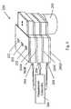
- FIG. 1is a schematic diagram of a device for processing a sample according to the present invention
- FIG. 2is a schematic diagram of the device of FIG. 1 , illustrating a compression member of a processing station of the device compressing the sample vessel;
- FIG. 3is a schematic diagram of an alternative embodiment of a device for processing a sample according to the present invention.
- FIG. 4is a schematic diagram of an alternative embodiment of a device for processing a sample according to the present invention.
- FIG. 5is a perspective view of an embodiment of a hand held device for processing a sample according to the present invention.
- FIG. 6is a perspective view of an embodiment of a bench top device for processing a sample according to the present invention.
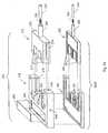
- FIG. 7is a perspective view of the device of FIG. 6 , illustrating the device with the top cover removed;
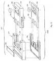
- FIG. 8is a perspective view of an embodiment of a thermal cycling processing unit according to the present invention.
- FIG. 9is a perspective view of the processing unit of FIG. 8 ;
- FIG. 10is a partially exploded, perspective view of a processing station of the processing unit of FIG. 8 , illustrating a heat block unit and an insulator block unit of the processing station;
- FIG. 11is a partially exploded, perspective view of the processing unit of FIG. 8 , illustrating a plurality of heating block units and insulator block units;
- FIG. 12is a partially exploded, perspective view of a processing station of an alternative embodiment of a processing unit according to the present invention.
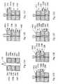
- FIGS. 13A-13Gare side elevational views, in cross-section, of a processing unit of the present invention, illustrating the operation of the processing unit;
- FIG. 14is a side elevational view, in cross section, of a gel electrophoresis analysis unit of the present invention.
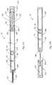
- FIGS. 15A-15Bare side elevational views, in cross-section, of embodiments of a sample vessel according to the present invention.
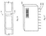
- FIG. 16is a side elevation view, in cross section, of a portion of a sample vessel according to the present invention, illustrating an injection channel formed in the sample vessel;
- FIG. 17is a side elevational view of a reagent cartridge according to the present invention.
- FIG. 18is a side elevational view, in cross-section, of a sample vessel according to the present invention.
- FIGS. 19A-19Cillustrate an alternative embodiment of a processing unit of the present invention.
- processinggenerally refers to the preparation, treatment, analysis, and/or the performance of other testing protocols or assays on a content of the sample vessel in one or more steps.
- Exemplary processing stepsinclude, for example: displacing a content, e.g., the sample or a reagent, of the sample vessel within the sample vessel to, for example, adjust the volume of the content, separate content components, mix contents within the sample vessel; effecting a chemical or biological reaction within a segment of the sample vessel by, for example, introducing a reagent to the sample, agitating the sample, transferring thermal energy to or from the sample, incubating the sample at a specified temperature, amplifying components of the sample, separating and/or isolating components of the sample; or analyzing the sample to determine a characteristic of the sample, such as, for example, the quantity, volume, mass, concentration, sequence, or nucleic acid size or other analyte size, of the sample.
- a characteristic of the samplesuch as, for example, the quantity, volume,
- a device for processing a sample according to the present inventioncan integrate one or more processing units into a single system depending on the process being employed.
- the processing unitscan include one or more processing stations at which one or more processing steps can be performed on the sample within the sample vessel.
- Sample materials that can be processed according to the present inventionare generally biological samples or samples containing biological substance and include, for example, blood, urine, saliva, cell suspensions, biofluids, a piece of tissue, soil or other samples.
- a sample processing device of the present inventionis particularly suited for nucleic acid amplification, such as polymerase chain reaction (PCR) or ligase chain reaction (LCR) amplification, and can include, for example, a sample pretreatment unit for extracting nucleic acid from sample, a thermal cycling reaction unit for amplification of the nucleic acid or signal, and (optionally) an analysis or detection unit for analyzing the amplified product.
- the sample processing device of the present inventioncan also be used for isothermal reaction of nucleic acid or signal amplifications, such as strand displacement amplification (SDA), rolling circle amplification (RCA), and transcription-mediated amplification (TMA).
- SDAstrand displacement amplification
- RCArolling circle amplification
- TMAtranscription-mediated amplification
- exemplary processes to be performed on samplescan include clinical diagnosis, therapeutic monitoring, and screening of chemical compounds for discovery of new drugs.
- the following descriptionprimarily focuses on PCR amplification for illustration. However, one skilled in the art will appreciate that the devices and methods of the present invention are not limited to PCR amplification, as the devices and methods described below can be employed in other sample processing.
- FIG. 1An exemplary embodiment of a device for processing a sample is illustrated in FIG. 1 .
- the processing device 10 illustrated in FIG. 1includes a processing unit 12 having an opening 14 to receive a sample vessel 16 .
- the opening 14can be a tubular shaped opening, an open-faced slot or other structure for receiving the sample vessel 16 in a removable and replaceable manner.
- the processing unit 12includes a first processing station 18 and a second processing station 20 , each positioned along the length of the opening 14 .
- the first processing station 18includes a compression member 22 adapted to compress the sample vessel 16 within the opening 14 and thereby displace a content of the sample vessel within the sample vessel 16 .
- the content of the sample vesselcan be, for example, the sample, a reagent contained within the sample vessel, or a mixture of the sample and the reagent.
- a driver 24is coupled to the compression member 22 to selectively move the compression member 22 and thereby compress the sample vessel 16 within the opening 14 .
- the driver 24can be, for example, an electromagnetic actuating mechanism, a motor, a solenoid, or any other device for imparting motion, preferably reciprocal motion, to the compression member 22 , as described in further detail below.
- the compression member 22is constructed from a rigid material such as a rigid plastic or a metal.
- the compression membercan be constructed in any shape sufficient to impart a compressive force on the sample vessel.
- the compression member 22can be a block having a rectilinear, planar surface for engaging the sample vessel 16 , as illustrated in FIG. 1 .
- the compression membercan have a curved, angular, or non-planar surface for engaging the sample vessel 16 .
- the compression member 22alternatively can be an inflatable membrane that can be inflated by a fluid, e.g., air, nitrogen, saline, or water, to impart a compressive force on the sample vessel.
- a fluide.g., air, nitrogen, saline, or water
- the amount of compression of the sample vesselmay be controlled by the adjusting the inflation pressure of the membrane.
- the first processing station 18can optionally include a stationary member 26 positioned opposite the compression member 22 across the opening 14 .
- the compression member 22thus, can compress a portion of the sample vessel 16 within the opening 14 against the stationary member 26 , as illustrated in FIG. 2 .
- the stationary member 26may be replaced with a second compression member, such that the processing station includes two compression members that move together to compress the sample vessel therebetween.
- a stationary member or second compression membermay be omitted by securing the sample vessel 16 within the opening on either side of the compression member.
- the sample vessel 16is a closed tubule flow-chamber for holding the sample.
- one or more segments of the sample vessel 16are constructed of a flexible, compressible material, such as, for example, polyethylene or polyurethane, to allow selective compression, and preferably flattening, of the sample vessel to move the sample, or other contents of the sample vessel, within the sample vessel, preferably while the sample vessel 16 remains in the device 10 .
- the sample vessel 16includes a plurality of segments separated by an integral, internal structure, such as a micro-fluidic pressure gate, as described in more detail below.
- sample vessel 16can be constructed without internal, integral structures to form segments and the device 10 can be utilized to segment the sample vessel by compressing selective portions of the sample vessel.
- the device 10can be utilized to segment the sample vessel by compressing selective portions of the sample vessel.
- sample vesselssuitable for containing a sample may be used with the device 10 without departing from the scope of the present invention.
- the second processing station 20can include a sensor 28 for detecting a signal from the content, e.g., the sample or a reagent, of the sample vessel 16 .
- the sensor 28can be an optical sensor for measuring light, for example fluorescent light, emitted from the sample or from fluorescent probes within the sample.
- multiple sensors or a spectrum sensorcan be used when detection of multiple wavelength light is required.
- the detected signalcan be sent to a CPU 30 to analyze the detected signal and determine a characteristic of the sample.
- a samplecan be introduced to a first segment A of the sample vessel 16 by injecting the sample through the walls of the sample vessel 16 or by introducing the sample through an opening formed in the sample vessel 16 , as described in more detail below.
- the sample vessel 16includes a pressure gate 32 that divides the sample vessel 16 into a first segment A and a second segment B.
- the sample vessel 14can be inserted into the opening 14 of the device 10 such that the first segment A of the sample vessel 16 is aligned with the first processing station 18 and the second segment B is aligned with the second processing station 20 , as illustrated in FIG. 1 .
- the driver 24can operate to move the compression member 22 into contact with the sample vessel 16 such that the first segment A of the sample vessel 16 is compressed within the opening 14 between the compression member 22 and the stationary member 26 .
- a quantity of sampleis displaced from the first segment A to the second segment B through the pressure gate 32 .
- the volume of sample displacedis proportional to the amount of compression of the first segment A by the compression member 22 .
- the compression member 22 of the first processing station 18can be used to displace a specific quantity of sample into the second segment B of the sample vessel 16 for analysis at the second processing station 20 .
- Substantially all of the samplecan be displaced from the first segment A of the sample vessel 16 by completely flattening the first segment A of the sample vessel 16 , as illustrated in FIG. 2 .
- the samplecan be analyzed in the second segment B of the sample vessel 16 at the second processing station 20 .
- FIG. 3An alternative embodiment of a device for processing a sample is illustrated in FIG. 3 .
- the device 38includes a processing unit 40 having three processing stations positioned along the opening 14 , namely, a first process station 42 , a second processing station 44 adjacent the first processing station 42 , and a third processing station 46 adjacent the second processing station 44 .
- the first processing station 42includes a compression member 22 coupled to a driver 24 and adapted to compress a segment of the sample vessel 16 against a stationary member 26 within the opening 16 .
- the first processing station 42can operate to displace a selective quantity of the sample from a first segment A of the sample vessel into other segments of the sample vessel.
- the second processing station 44includes a compression member 22 coupled to a driver 24 and adapted to compress a second segment B of the sample vessel 16 against a stationary member 26 within the opening 16 .
- the second processing station 44includes an energy transfer element 48 for transferring energy to or from the contents of the sample vessel 16 .
- the energy transfer element 48can be, for example, an electronic heat element, a microwave source, a light source, an ultrasonic source, a cooling element, or any other device for transferring energy. In one embodiment, the energy transfer element 48 transfers thermal energy to or from the sample within the sample vessel.
- the energy transfer element 48can be embedded in or otherwise coupled to the compression member 22 , as illustrated in FIG. 3 .
- the energy transfer element 48can be coupled to the stationary member 26 or can be positioned within the processing station independent of the compression member or the stationary member.
- the energy transfer element 48can be coupled to a control system that controls the energy transferred to or from the sample vessel 16 by the energy transfer element 48 .
- the control systemcan be a component system of the CPU 30 or can be an independent system.
- the control systemcan also include a temperature sensor 50 to monitor the temperature of the energy transfer element.
- the second processing station 44also can include a sensor 52 for detecting a signal from the content of the sample vessel, particularly during processing in the second processing station.
- the sensor 52can be an optical sensor for measuring light, for example fluorescent light, emitted from the sample or from fluorescent probes within the sample.
- the sensor 52can be coupled to the CPU 30 for analysis of the detected signal to determine a characteristic of the sample.
- the third processing station 46can include a sensor 28 for detecting a signal from the content, e.g., the sample or a reagent, of the sample vessel 16 .
- the sensor 28can be an optical sensor for measuring light, for example fluorescent light, emitted from the sample or from fluorescent probes within the sample.
- multiple sensors or a spectrum sensorcan be used when detection of multiple wavelength light is required.
- the detected signalcan be sent to a CPU 30 to analyze the detected signal and determine a characteristic of the sample.
- a samplecan be introduced into a first segment A of the sample vessel 16 and the sample vessel 16 can be introduced into the opening 14 of the device 10 .
- the sample vessel 16includes two pressure gates 32 that divide the sample vessel 16 into three segments, namely, the first segment A, a second segment B, and a third segment C.
- the first processing station 42can operate to displace a selective amount of the sample into the second segment B of the sample vessel 16 for processing at the second processing station 44 .
- energycan be transferred to or from the sample within the second segment B.
- a biological or chemical reaction involving the samplemay be carried out in the second segment B.
- the sensor 52can be used to monitor the reaction during the reaction process.
- the samplecan be moved into the third segment C of the sample vessel 16 by compressing the sample vessel 16 within the opening at the second processing station 44 .
- the compression member 22 of the first processing station 42substantially flattens the first segment A of the sample vessel 16 to inhibit the sample from entering the first segment A.
- the samplecan be analyzed in the third segment C of the sample vessel 16 at the third processing station 46 .
- FIG. 4A further embodiment of a device for processing a sample is illustrated in FIG. 4 .
- the device 56includes a processing unit 58 having a processing station 60 positioned along the opening 14 .
- the processing station 60includes a compression member 22 coupled to a driver 24 and adapted to compress a segment of the sample vessel 16 against a stationary member 26 within the opening 16 .
- the sample vessel 16includes a pressure gate 32 that divides the sample vessel 16 into two segments, namely, a first segment A and a second segment B.
- the processing station 60can operate to displace a selective quantity of the content from the second segment B of the sample vessel into the first segment A of the sample vessel. For example, a reagent can be introduced into the second segment B of the sample vessel 16 .
- a quantity of reagentcan be displaced from the second segment B into the first segment A of the sample vessel 16 to mix with the sample in the first segment A.
- the reagentcan be introduced into the first segment A of the sample vessel 16 and a quantity of the sample can be displaced from the second segment B into the first segment A by the processing station 60 .
- the first segment A of the sample vessel 16can act as a reaction mixture chamber for the sample and the reagent.
- the reagentcan be pre-packaged in the sample vessel 16 or can be introduced to the sample vessel 16 after the sample is introduced to the sample vessel 16 .
- the reagentcan be introduced using a reagent injector cartridge, described below, that is included with the device.
- the illustrated device 100is a hand held system for processing a nucleic acid sample, preferably in an “insert and test” format in which a sample vessel containing a nucleic acid sample is inserted into the device 100 and processing results are produced by the device with minimal human intervention.
- the device 100can include a housing 112 having an opening 114 for receiving a sample vessel 116 containing a sample for processing by the device 100 .
- the opening 114can be a tubular shaped opening, as illustrated in FIG. 5 , or can be an open-faced slot or other structure for receiving the sample vessel in a removable and replaceable manner.
- a control panel 118is located on the top of the housing 112 for inputting information to the device 100 and a monitor 120 is provided for displaying operating information, such as the results of processing.
- An external communication port 121can be located on the housing 112 for receiving information or outputting information, such as the results of processing and remote diagnosing of the system, to a remote system, such as a computer network.
- a battery 123( FIG. 7 ) can be located within the housing to provide electrical power to the components of the device 100 .
- a multi-sample device 200 for processing multiple samplesis illustrated in FIG. 6 .
- the device 200is a bench top thermal cycling system for processing up to 96 nucleic acid samples simultaneously.
- the sample processing device 200operates on the same principles as the sample processing device 100 illustrated in FIG. 5 , except that the multi-sample device 200 provides increased capacity and throughput.
- the multi-sample processing device 200can include a housing 202 having a plurality of wells or openings 204 , with each well being capable of receiving a sample vessel 206 containing a sample for processing by the device.
- the exemplary multi-sample device 200 illustrated in FIG. 6has ninety-six wells for treating up to 96 samples simultaneously.
- a control panel 208is located on the top of the housing 202 for inputting information to the multi-sample processing device 200 and a monitor 210 is provided for displaying operating information, such as the results of testing.
- FIG. 7illustrates the general components of the sample processing device 100 illustrated in FIG. 5 .
- the illustrated device 100includes three primary processing units for processing a sample within the sample vessel, namely, a pretreatment unit 122 for pretreating the sample, a reaction unit 124 for amplifying certain components of the sample, and an analysis unit 126 for analyzing the sample.
- the sample vesselcan be loaded into the device 100 through the opening 114 .
- the processing units of the deviceare preferably arranged along the axis of elongation of the opening 114 . This arrangement allows the sample to be moved within the sample vessel between the processing units of the device 100 in a manner described in detail below.
- the processing unitsare arranged linearly as illustrated in FIG. 7 , however, other arrangement are possible so long as the sample vessel can be positioned adjacent one or more of the processing units of the device 100 .
- a pair of sample vessel loading wheels 128is located at the entrance 130 of the sample vessel opening 114 .
- the entrance 130is preferably tapered to facilitate loading of the sample vessel into the opening 114 of the device 100 .
- the loading wheels 128further facilitate loading of the sample vessel by guiding the sample vessel into the opening 114 .
- a sample collection unit 132can be positioned proximate the entrance 130 of the opening 114 to allow a selective volume of the sample to dispense into the next processing unit or units within the sample vessel.
- the sample collection unit 132can include a compression member 22 opposed to a stationary member 26 across the width of the opening 114 .
- a linear motor 138is coupled to the compression member 22 .
- the linear motor 138can operate to move the compression member 22 toward or away from the stationary member 26 to selectively open and close the opening 114 therebetween.
- the linear motor 138can operate to compress the sample vessel between the compression member 22 and the stationary member 26 .
- a selective volume of the samplecan be moved to the next processing unit within the sample vessel.
- the sample vesselremains compressed between the compression member 22 and the stationary member 26 of the sample collection unit 132 during processing of the sample by the other processing units to prevent the sample from exiting the processing unit area during processing.
- the pretreatment unit 122is positioned adjacent the initial sample collection unit 132 .
- the samplemay require pretreatment or preparation before proceeding with additional processing steps.
- Pretreatmentcan include, for example, adding a reagent or other material to the sample and incubating the mixture for certain time period.
- the pretreatment unit 122 of the device 100allows for any of such pretreatment steps to be implemented.
- the sample pretreatment unit 122can provide for nucleic acid extraction from a biological sample, such as blood. Any known methods for extracting nucleic acid can be utilized in the pretreatment unit, including using a cell lysis reagent, boiling the nucleic acid sample, GITC, or formamide for solubilization. Alternatively, filters can be used within the sample vessel to separate nucleic acid from unwanted cellular debris.
- the pretreatment unit 122can include a compression member 22 and a stationary member 26 opposed to the compression member 22 across the opening 114 .
- the compression member 22 and/or the stationary member 26can optionally include an energy transfer element for transferring energy, e.g. thermal energy, to the sample within the sample vessel.
- the energy transfer elementcan be, for example, an electronic heat element (such as Kapton heater, a Nomex heater, a Mica heater, or a silicone rubber heater), a microwave generator, a light source, an electronic cooling element (such as Peltier element), an ultrasonic energy transfer element, or any another device suitable for transferring thermal energy.
- a driver 24for example an electromagnetic actuator such as linear stepper actuator, a relay actuator, or a solenoid, is coupled to the compression member 22 and operates as a driver.
- the driver 24moves the compression member 22 to open the opening 114 between the compression member 22 and the stationary member 26 of the pretreatment unit 122 to allow receipt of a sample vessel.
- the driver 24drives the compression member 22 toward the stationary member 26 , resulting in good surface contact between the sample vessel and the compression member and the stationary member and thus improved pretreatment.
- the driver 24moves the compression member 22 of the pretreatment unit 122 to further compress the pretreatment segment of the sample vessel to move a selective amount of pretreated sample within the sample vessel to the next processing unit.
- the reaction unit 124can include a plurality of processing stations 150 A- 150 C and is preferably positioned adjacent the pretreatment unit 122 .
- the reaction unit 124can effect thermal cycling of the sample by selectively moving the sample, with the sample vessel, between the processing stations 150 A- 150 C.
- thermal cyclingrefers to a process of heating and/or cooling a sample in two or more steps, with each step preferably occurring at a different temperature range from the previous step.
- Each of the processing stations 150 A- 150 Ccan be maintained at a pre-selected temperature range controlled by a temperature control system 152 and a CPU 174 .
- the reaction unit 124can include any number of processing stations 150 , depending on the thermal cycling process employed.
- the reaction unit 124can incubate a sample at a selective temperature for an isothermal reaction such as for TMA or SDA process.
- thermal cyclingcan be used to denature, anneal, elongate and thereby amplify the nucleic acid sample.
- the PCR thermal cycling stepseach occur at specified temperature ranges. Denaturing occurs at approximately 92° C.-96° C.; elongation occurs at approximately 70° C.-76° C.; and annealing occurs at approximately 48° C.-68° C.
- Each of the PCR thermal cycling stepsi.e. denaturing, annealing, and elongation, can be carried out independently at a separate processing station of the reaction unit 124 by maintaining the processing stations at the temperature ranges effective for carrying out each of the PCR thermal cycling steps.
- the denaturing stepcan be carried out at processing station 150 A, the elongation step at processing station 150 B, and the annealing step at processing station 150 C.
- one or more of the PCR thermal cycling stepscan be combined and carried out at the same processing station, thereby reducing the number of processing stations required.
- denaturingcan be carried out at processing station 150 A and elongation and annealing can be carried out at processing station 150 B, thus, eliminating the need for a third processing station.
- a processing stationcan be provided within the reaction unit 122 for cooling of the sample by using a thermal energy element, a Peltier thermal electric element for example, to transfer thermal energy from the processing station.
- a processing stationcan be provided to preserve the nucleic acid sample between process steps by cooling the sample to a refrigeration temperature, e.g., 4° C.
- a processing stationcan optionally be provided to cool the sample between thermal cycling steps to decrease the temperature down ramping time between successive thermal cycling steps. For example, as denaturing generally occurs at 92° C.-96° C. and annealing generally occurs at a significantly lower temperature, e.g., 48° C.
- the samplecan be cooled after denaturing in a cooling processing station, preferably at a temperature lower than the annealing temperature, to bring the sample temperature more quickly into the annealing temperature range.
- a thermal cycling processing stationcan optionally include a heat sink 166 coupled to either the compression member 22 or the stationary member 26 to conduct heat away from the station and radiate the heat to the environment.
- Each of the illustrated processing stations of the reaction unit 124includes a compression member 22 and a stationary member 26 .
- the compression member 22 of each thermal cycling processing unitcan be coupled to a driver 24 for selectively moving the compression member 22 toward and away from the stationary member 26 .
- the drivers 24can be any device capable of imparting motion, preferably reciprocal motion, to the compression members.
- a driver control system 160is coupled to the drivers 24 to control the operation of the drivers 24 .
- the drivers 24are electromagnetic actuators coupled to the driver control system 160 , which can be, for example, a control system for controlling the reciprocal motion of the actuators.
- Alternative drivers, compression members and stationary membersare described below in connection with FIGS. 8-12 .
- the driver control system 160is coupled to the CPU 174 such that the sample incubation time period, the pressure and the sample moving speed within the sample vessel can be controlled and coordinated by the CPU 174 to achieve the best reaction results.
- Each of the thermal cycling processing station 150 A- 150 Ccan optionally include an energy transfer element for transferring energy, such as thermal energy, to the sample within the sample vessel.
- the energy transfer elementscan be, for example, an electronic heat element, a microwave generator, a light source, an electronic cooling element, or any another device suitable for applying thermal energy.
- Each of the energy transfer elementsis coupled to the temperature control system 152 to maintain the associated processing station within a selected temperature range.
- One or more temperature sensors, coupled to the temperature control system 152can be positioned proximate the processing stations 150 A- 150 C to monitor the temperature of the stations.
- At least one layer of energy insulator 146can optionally be provided to insulate the processing unit or the processing station from adjacent units or stations.
- An energy insulator layercan also be formed on the boundary of a processing station to prevent energy transfer to or from the environment.
- the energy insulator 146can be, for example, an energy shielding layer, an energy absorption layer, an energy refraction layer, or a thermal insulator, depending on the type of energy transfer element employed.
- a thermal insulatorcan be constructed from a low thermal conductivity material such as certain ceramics or plastics. In one embodiment, the thermal insulator can be attached to the compression members and the stationary members.
- the thermal insulatorscan be separate from the compression members and stationary members and can be controlled independently by a driver to open and close the opening 114 .
- all the compression members and insulatorscan open initially to allow loading of the sample vessel, and then, the thermal insulators can compress the sample vessel within the opening to close the vessel and form separate segments within the sample vessel.
- a spring element or other biasing mechanismcan be optionally utilized to bias each thermal insulator. Through the spring element, a driver associated with one of the thermal insulators can apply sufficient pressure on the thermal insulator to minimize the quantity of sample remaining in the junction between adjacent processing stations during an incubation period, while still allowing sample flow through the thermal insulator when a higher pressure is applied to the sample in an adjacent processing station. This design simplifies the operation of multiple thermal insulators.
- the processing stationscan be spaced apart to inhibit conductive heat transfer between adjacent processing stations and, thereby, eliminate the need for insulators between the stations.
- the thermal cycling processbegins by opening each of the processing stations, e.g. first processing station 150 A, second processing station 150 B, and third processing station 150 C, to receive the sample vessel within the opening 114 , as illustrated in FIG. 13A .
- the second processing station 150 B and the third processing station 150 Care closed by moving the compression member 22 B and the compression member 22 C of each station toward the respective stationary member 26 B and 26 C, as illustrated in FIG. 13B .
- the second processing station 150 B and the third processing station 150 Care closed, the sample vessel is compressed between the compression member and the stationary member, displacing the sample within the sample vessel into a segment of the sample vessel adjacent the first processing station 150 A.
- the compression member 22 A and the insulator 146 Acan compress the sample vessel to adjust the sample volume contained within the segment of the sample vessel adjacent the first processing station 150 A, as well as the surface area to volume ratio of the segment.
- the insulator 146 Acan then be closed to seal the sample in the first processing station 150 A, as illustrated in FIG. 13C .
- the sample pretreatment unitcan function to close the sample vessel within the first processing station 150 A.
- Other alternativesinclude pre-sealing the sample vessel after loading a sample, or providing the sample vessel with pressure gates, discussed below, formed between adjacent reaction zones.
- the samplecan be heated to a temperature effective to denature the nucleic acid sample.
- the sample vesselis pressed into contact with the compression member 22 A and the stationary member 26 A by the compression member 22 A to flatten the sample vessel and to ensure good thermal contact between the sample vessel and the compression member 22 A and the stationary member 26 A.
- the compression member 22 Acan also optionally periodically squeeze the sample vessel to agitate the sample and to generate sample flow in the segment of the sample vessel during the reaction period to speed up the reaction.
- the second processing station 150 Bcan be opened to allow the sample to move into the second processing station 150 B, as illustrated in FIG. 13D .
- the first processing station 150 Acloses, compressing the sample vessel and moving the entire sample, within the vessel 16 , into a segment of the sample vessel adjacent the second processing station 150 B, as illustrated in FIG. 13E .
- the third processing station 150 Ccan then open to allow the sample to move into the segment of the sample vessel adjacent the third processing station 150 C, as illustrated in FIG. 13F .
- the second processing station 150 Bcloses, compressing the sample vessel and moving the sample completely into the segment of the sample vessel adjacent the third processing station 150 C, as illustrated in FIG. 13G .
- the samplecan then be heated or cooled by the third processing station 150 C for a set time period.
- the samplecan be heated to a temperature effective to anneal the nucleic acid sample in the third processing station 150 C.
- the heat sink 166can facilitate the temperature transition from the denaturing temperature of the first processing station 150 A to the annealing temperature of the third processing station 150 C by dissipating excess heat to the environment.
- the samplecan be moved from the denaturing step at the first processing station to the annealing step at the third processing station.
- the second processing station 150 Bopens to allow the sample to move into the second processing station, as illustrated in FIG. 13F .
- the third processing station 150 Cthen closes, compressing the sample vessel 16 and moving the sample entirely into the segment of the sample vessel adjacent the second processing station 150 B, as illustrated in FIG. 13E .
- the samplecan then be heated or cooled by the second processing station 150 B for a set time period. In PCR thermal cycling for example, the sample can be heated to a temperature effective to elongate the nucleic acid sample.
- the sampleUpon conclusion of the elongation step, the sample can be returned to the segment of the sample vessel adjacent the first processing station 150 A to repeat the cycle, i.e., denaturing and annealing and elongating or, the sample can be moved to a segment of the sample vessel adjacent the sample detection unit 126 if PCR thermal cycling is completed.
- the illustrated thermal cycling reaction unit 124provides denaturing in the first processing station 150 A, annealing in the third processing station 150 C, and elongation in the second processing station 150 B, as this arrangement is deemed thermodynamically efficient.
- PCR thermal cycling stepscan occur in any of the processing stations without departing from the scope of the present invention.
- Sample thermal cycling using the reaction unit 124 of the present inventionresults in faster thermal cycling times and lower energy consumption compared to conventional thermal cycling devices.
- Sample vessel shape alteration, i.e. flattening, by the reaction unit 124results in significant increases in the surface/volume ratio and sample vessel contact with the members of the reaction unit. This allows the processing stations of the reaction unit 124 to heat the sample more directly, increasing the sample temperature ramping rate and avoiding unnecessary temperature ramping of the members and thus decreasing the amount of energy consumed. Equally important is that sample vessel shape alteration provides for the uniform transfer of thermal energy to the sample, dramatically reducing reaction mixture temperature gradients.
- the reaction unit 124further allows the use of fluid flow to mix the sample as the sample is moved from one processing station to another.
- reaction unit 124allows the use of a disposable, single-use sample vessel that minimizes contamination of the sample, contamination of the reaction unit and exposure of the operator to biohazards. Additionally, the reaction unit 124 does not require a fluid handling system, as the sample can be moved within the sample vessel during processing.
- the reaction unit 124can optionally include a reaction sensor 168 for monitoring the reaction in real-time within the reaction unit 124 by analyzing the sample, including any reaction products from the reaction with the sample.
- the reaction sensor 168can include an integral light source 169 for applying excitation energy to the sample within the sample vessel. Alternatively, a light source, or other source of excitation energy, can be provided separate from the reaction sensor 168 .
- the reaction sensor 168can be an optical sensor for measuring light, for example fluorescent light, emitted from the sample or from fluorescent probes within the sample.
- any known real-time PCR detection systemcan be employed, including, for example, using fluorescent dyes, such as ethidium bromide, intercalating into the DNA molecule, using a dual labeled probe tagged with a reported dye and a quenching dye, or using hybridization probes, which will result in Fluorescence Resonance Energy Transfer (FRET) only when the two probes are hybridized and in close proximity.
- FRETFluorescence Resonance Energy Transfer
- the fluorescence signalis substantially proportional to the amount of specific DNA product amplified.
- the reaction detection sensor 168is placed to monitor the fluorescence from the sample, preferably in the annealing processing station, or other processing stations of the reaction unit, dependent on the assay selected. Multiple sensors or a spectrum sensor can be used when detection of multiple wavelength light is required. The detected signal is then sent to the CPU 174 for further analyzing the amount of product.
- the sample detection or analysis unit 126 of the device 100is provided to analyze the sample after processing by the reaction unit 124 .
- the analysis unit 126is preferably positioned proximate the reaction unit 124 .
- a source of excitation energyfor example a light source
- a signal detectorfor example an optical sensor
- Specific illustrative practicesinclude detecting the transmission of light through the sample, detecting reflected light, detecting scattering light, and detecting emitted light.
- the detected lightin the form of the signal output from the sensor, can be analyzed by a CPU 174 provided in the device through known signal processing algorithms.
- Suitable sample analysis systemsemploying a light source and an optical sensor or sensors, detects signals including light intensity at a given wavelength, phase or spectrum of the light, as well as location of the signal.
- the flow induced testing system described in U.S. Pat. No. 6,318,191 and the multi-layer testing system described in U.S. Pat. App. Pub. No. US 2004/0105782 A1both of which are incorporated herein by reference, describe suitable sample analysis systems.
- gel electrophoresis or capillary electrophoresiscan be employed to analyze the nucleic acid sample, as illustrated in FIGS. 7 and 14 .
- Suitable nucleic acid sizing gelsinclude agarose and polyacrylamide.
- the gel 184can be introduced to the sample vessel 16 during processing or, preferably, is pre-loaded into an analysis segment 210 of the sample vessel, as discussed in more detail below.
- the exemplary analysis unit 126includes a light source 170 for illuminating the nucleic acid sample and the gel and an optical sensor 172 in the form of linear charge coupled device (CCD).
- Electrode activators 176operate to insert a positive electrode 180 and a negative electrode 182 into the sample vessel 16 .
- the positive electrode 180 and the negative electrode 182are electrically connected to a voltage source, which creates a voltage difference between the electrodes.
- a voltage sourcewhich creates a voltage difference between the electrodes.
- the gelseparates the sample components by size, allowing smaller components, such as nucleic acid products, to travel faster, and thus, further, than larger components.
- a suitable dye or fluorescent tagcan be introduced to gel to identify the nucleic acid products.
- Light from the light source 170can illuminate the dyed or tagged nucleic acid products in the gel and the optical sensor 172 can then identify the illuminated nucleic acid products.
- the output signal of the optical sensor 172can be analyzed by CPU 174 according to known signal processing method to determine the presence, absence, quantity or other condition of the nucleic acid sample.
- the nucleic acid samplecan be analyzed in accordance with conventional nucleic acid analysis methods, such as, for example, chemiluminescence, fluorescently labeled primers, antibody capture, DNA chip, and/or magnetic bead detection methods.
- conventional nucleic acid analysis methodssuch as, for example, chemiluminescence, fluorescently labeled primers, antibody capture, DNA chip, and/or magnetic bead detection methods.
- sample processing device of the present inventioncan be arranged in any order depending on the sample being processed and the process being utilized.
- the sample processing device of the present inventionmay include any combination of the processing units and processing stations described herein, as well as additional processing units and processing stations that will be apparent to those skilled in the art upon reading this disclosure.
- the sample processing devicemay include only a single processing unit, such as, for example, a reaction unit for thermal cycling a sample, or may include a only a single processing station, such as, for example, a processing station for displacing a specified volume of reagent or sample.
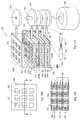
- FIGS. 8-12illustrate alternative embodiments of a reaction unit 250 for thermal cycling a sample according to the present invention.
- the reaction unit 250can include one or more openings 252 for receiving one or more sample vessels 16 .
- the embodiments illustrated in FIGS. 8-12have three openings 252 , permitting the simultaneous thermal cycling of up to three samples.
- the reaction unit 250comprises three processing stations: a first processing station 254 , a second processing station 256 , and a third processing station 258 .
- Thermal insulators 260 A- 260 Dare positioned between the processing stations and at the top of the first processing station 254 and the bottom of the third processing station 258 .
- the first processing station 254includes an embedded heat element 262 for transferring thermal energy to the sample vessel when the sample vessel is positioned within an opening 252 .
- the heat element 262can be a Kapton heater, a Nomex heater, a Mica heater, a silicone rubber heater or any other thermal energy transfer element suitable for delivering thermal energy.
- the heat element 262can be seated in a recess 264 formed in the processing station 254 and secured to the processing station by an adhesive or other attachment means.
- the heat element 262 of each of the processing stationsis preferably coupled to a temperature controller 266 for controlling the temperature of the heat element.
- One or more temperature sensors 268can be positioned in the processing station 254 to measure the temperature of the processing station 254 .
- the temperature sensor 268can be coupled to the thermal controller 266 such that the temperature controller 266 can monitor and adjust the temperature of the processing station in a feedback control manner.
- each processing stationcomprises a stationary member 270 and a compression member 272 adapted to compress the sample vessel selectively within one or more of the openings 252 and thereby move the sample within the sample vessel.
- the compression member 272is preferably complimentary in shape to the stationary member 270 and includes a plurality of finger-like closure elements or shutters 274 sized and shaped to slide within the openings 252 .
- Guide rails 276are positioned on either side of the compression member.
- the guide rails 276are preferably sized and shaped to fit within grooves 278 formed in the side walls of the stationary member 270 .
- the combination of the guide rails 276 and the grooves 280allow the compression member 272 to reciprocate relative to the stationary member 270 to selectively open and close the openings 252 .
- Each thermal insulator 260can be configured in a manner analogous to the processing stations.
- the thermal insulator 260 Bcomprises an insulator stationary member 280 and an insulator compression member 282 adapted to compress a sample vessel within one or more of the openings 252 .
- the insulator compression member 282includes a plurality of finger-like closure elements or shutters 284 sized and shape to slide within the openings 252 to selectively open and close the openings 252 .
- Each compression member 272 and insulator compression member 282is coupled to a driver, such as an electromagnetic driver mechanism, as described above, or any other mechanism for imparting motion, preferably reciprocating motion, to the compression members.
- a driversuch as an electromagnetic driver mechanism, as described above, or any other mechanism for imparting motion, preferably reciprocating motion, to the compression members.
- Each compression membercan be coupled to an arm 286 for providing a connection between the compression member and the driver, as best illustrated in FIGS. 9-11 .
- the arms 286are hollow tubes that receive coiled springs 288 and dowels 290 .
- the springs 288operate to bias the compression members 272 , 282 in a direction away from the stationary member 270 and the insulator stationary member 280 , respectively.
- An elastic elementsuch as the coiled spring used here, provides a simple mechanism for assisting the driver to regulate the compressing pressure applied to the sample vessel.
- the drivercan be a motor 292 for driving a rotating shaft, as best illustrated in FIG. 8 .
- the rotary motion of the shaftcan be translated to reciprocating motion through cams 294 provided for each of the compression members 272 and 282 .
- the cams 294are coupled to the arms 286 .
- the cams 294can be configured to selectively open and close the compression members 272 and 282 in accordance with conventional cam design methods.
- the compression members 272 and 282 of each of the processing stations and insulatorsinclude holes 296 for receiving a cam 294 and a linear spring element 298 .
- Spring elements 298each operate to bias a respective compression member in a direction away from the corresponding stationary member.
- the cams 294in combination with the springs 298 , act to impart reciprocating motion to the actuators and regulate the compressing pressure on the sample vessel.
- FIGS. 19A-19Cillustrate a further embodiment of the reaction unit of the present invention.
- the reaction unit 350includes nine openings 352 for receiving up to nine sample vessels simultaneously.
- the reaction unit 350includes three processing stations: a first processing station 354 , a second processing station 356 , and a third processing station 358 .
- Thermal insulators 360 A- 360 Dare positioned adjacent each of the processing stations and at the top of the first processing station 354 and the bottom of the third processing station.
- Top thermal insulator 360 A and bottom thermal insulator 360 Dare movable independent of the first processing station 354 and the third processing station 358 , respectively.
- Intermediate thermal insulators 360 B and 360 Care coupled to the first processing station 354 and the second processing station 356 , respectively.
- Each processing stationcomprises a stationary member 370 and a complementary compression member 372 adapted to compress the sample vessel selectively within one or more of the openings 352 and thereby move the sample within the sample vessel.
- Each stationary member 370has a projection 374 aligned with one of the openings 352 .
- the compression members 372are each provided with a projection 376 , positioned on an opposite side of the opening 352 . When a compression member 372 is slid on the corresponding stationary member 370 , the projections 374 and 376 engage and close the openings 352 therebetween.
- Each compression member 372as well as intermediate thermal insulators 360 B and 360 C, include an arm 380 coupled by a cam 384 to a rotary shaft 382 .
- a stationary insulator member 362is coupled, and aligned with an edge of each opening 352 on each stationary member 370 .
- Each stationary insulator member 362is inserted in each of the openings of a movable insulator compression member 360 to react to compression and open or close the opening.
- the shaft 382is rotated by a stepper motor or a servo motor 386 .
- the cams 384translate the rotation of the shaft 382 into linear reciprocal motion, which is imparted to the arms 380 to effect selective opening and closing of the openings 352 and compression of the sample vessels therein.
- Each arm 380includes an inner shaft 390 received within an outer sleeve 392 .
- a spring 394is interposed between the inner shaft 390 and the respective compression member or thermal insulator.
- a second spring 396is positioned on an opposite side of the respective compression member or thermal insulator. The spring 394 cooperates with the second spring 396 to allow the compression member or thermal insulator to “float” along the axis of the arm 380 . In this manner, the arm 380 can apply sufficient force to the compression member or thermal insulator to compress the sample vessel within an opening 352 and, thereby, displace substantially all of the sample from the compressed portion of the sample vessel.
- An increase of pressure within the sample vesselfor example, from the compression of an adjacent portion of the sample vessel, however, can cause the sample to displace within the sample vessel through the compressed portion of the sample vessel, as the springs 394 and 396 will allow small axial movements of the compression member or thermal insulator.
- Each stationary member 370 and compression member 372can be provided with an embedded thermal energy transfer device 398 for each opening 352 to apply thermal energy to the sample vessel within the opening 352 .
- the stationary member 370 and compression member 372can include temperature sensors 399 associated with each energy transfer device 398 to monitor the temperature of the sample vessel.
- FIGS. 15A and 15Billustrate embodiments of a sample vessel 16 according to the present invention.
- the illustrated sample vessel 16is a closed tubule system that provides a disposable, single use container and reaction vessel for the sample.
- the sample vessel 16can be constructed of a resiliently compressible, flexible, and ultra-high strength material, such as polyethylene or polyurethane.
- the sample vessel 16can have a seamless, flattenable cross-sectional profile and thin-walled construction that is optimized for fast and uniform heat transfer, for maximum surface contact with the sample, and for high pressure resistance.
- the wallsare constructed to converge when the sample vessel is compressed in a direction perpendicular to the longitudinal axis of the sample vessel such that the volume of the compressed portion of the sample vessel decreases and the ratio of the surface area to the volume of the compressed portion increases, without fracturing of the sample vessel.
- the walls of the sample vessel 16have a wall thickness of approximately 0.01 mm to 0.5 mm. Experimental results indicate that constructing a sample vessel having a wall thickness within this preferred range significantly increases the efficiency of heat transfer to the sample.
- a two-layer wall structurecan be used, with the inner layer providing bio-compatibility, using material such as polyethylene or polyurethane, and the outer layer providing lower permeability, using material such as high density polyethylene or aluminum foil.
- the material selected to construct the portions of the wall of the sample vessel, such as a detection segment of the sample vessel 16can be optically transmissive over a selected wavelength range to facilitate optical analysis of the sample within the sample vessel.
- the sample vessel 16can be divided into multiple segments by one or more pressure gates 32 .
- the sample vesselcan be divided into a sample collection segment 205 , a sample pretreatment segment 206 , a sample reaction segment 208 , and a sample analysis segment 210 .
- the illustrated pressure gates 32are internal to the tubule structure of the vessel 16 and provide a fluid tight seal between the segments of the sample vessel 16 , under normal operating conditions.
- the pressure gatesare formed by placing the sample vessel between sealing heads, squeezing the sealing heads together under pressure to compress the sample vessel, and applying energy across the compressed vessel to create a seal. For example, RF energy or direct heat may be applied to create a heat seal.
- the pressure gatesare formed by a bonding of opposing wall portions of the vessel to one another. As shown in FIGS, 15 A-B, the resulting adjacent segments are separated from one another by only a pressure gate, and opposing wall portions of the vessel are not bonded to one another except at pressure gates.
- the pressure gatewhen formed, extends across the entire width of the vessel.
- the pressure gates 32open upon the application of pressure greater than a certain value, for example, approximately 2 or 3 atmospheres. When external pressure is provided to one segment, the pressure gate 32 can open, allowing the sample to flow from the high pressure compartment to the low pressure compartment.
- the sample vessel 16can include a handling portion having a generally rigid construction to facilitate handling of the sample vessel.
- the handling portioncan be coupled to one or more of the segments of the sample vessels used to contain the sample.
- the handling portioncan be a cylindrical sleeve constructed of a generally rigid material, such as a plastic or a metal, that is sized and shaped to fit over one or more of the segment of the sample vessel.
- the cylindrical sleevecan be removable and replaceable.
- the handling portioncan be a rigid segment, such as a rigid ring, positioned at an end of the sample vessel or between two segments of the sample vessel. In the embodiments illustrated FIGS. 15A and 15B , the handling portion is a segment of the sample vessel having an increased wall thickness.
- the sample collection segment 205 and the sample pretreatment segment 206have a wall thickness greater than the wall thickness of the reaction segment 208 .
- the increased wall thicknessprovides sufficient rigidity to the sample collection segment 205 and the sample pretreatment segment 206 to facilitate handling of the sample vessel 16 .
- the wall thickness of the handling portionis greater than 0.3 mm.
- the sample vessel 16can include an instrument, such as a sampling pipette or a needle 107 , for direct collection of the sample to be treated and analyzed within the sample vessel 16 , as illustrated in FIG. 15A .
- the needle 207can be positioned at one end of the sample vessel 16 and can be connected to the sample collection chamber 205 through a conduit 209 formed in the wall of the sample vessel 16 .
- a needle cover 211can be provided to secure the needle 207 prior to and after use.
- the needle cover 211can be, for example, a penetrable rubber cover or a removable plastic cover.
- a sampling instrument 214such as a pipette, a stick, or a tweezer, can be coupled to a cover 212 that selectively closes the conduit or opening 209 formed in the wall of the sample vessel.
- the cover 212can include a reservoir 216 for containing a reagent and a sample during sampling. For sampling, the cover 212 can be removed from the sample vessel to expose the sampling instrument 214 .
- the sampling instrument 214can be used to collect the sample, by pipetting, swabbing, or gathering the sample, for example, and then the sampling instrument 214 can be inserted into the sample collection segment 205 through the conduit 209 .
- the samplecan then be introduced to the sample collection segment 205 by compressing the cover 216 to displace the sample from the reservoir 216 .
- the samplecan be introduced to the sample collection segment 205 or to another segment of the sample vessel, depending of the segments present in the sample vessel, after collection by a separate instrument.
- Sample vessel 16can be particularly suited for PCR testing using the sample processing device of the present invention, as described above.
- nucleic acid extractioncan be performed within the sample pretreatment segment 206 of such a sample vessel 16 .
- a cell lyses reagentfor example, GENERELEASER® from Bioventures, Release-ITTM from CPG Biotech, or Lyse-N-GoTM from Pierce, or other extraction reagents can be introduced to the pretreatment segment 206 to extract nucleic acid from the initial sample. Extraction reagents can be stored within the pretreatment segment 206 or can be delivered to the segment. Additionally, one or more filters can be positioned within the pretreatment segment 206 of the sample vessel to separate nucleic acid from unwanted cellular debris.
- a portion of pretreated samplecan be moved into the reaction segment 208 .
- a PCR reaction segment 208 of the sample vessel 16according to one illustrative practice of the invention has a wall thickness, indicated by reference character t in FIG. 15A , of approximately 0.01 mm-0.3 mm, a diameter of less than approximately 6 mm, and a length of less than approximately 30 mm.
- PCR reagentssuch as nucleotides, oligonucleotides, primers and enzymes, can be pre-packaged in the reaction segment or reaction segments 206 , or can be delivered, for example, through the walls of the sample vessel using a needle, using for example, a reagent injector cartridge described below, before moving the sample into the segment.
- a pre-packaged reagent storage segment 214can be used to stored a pre-packaged reagent.
- a reagent storage segmentcan be formed between any two adjacent processing segments and may store any reagent needed for a reaction.
- the reagent storage section 214can store PCR reagents, while reagent storage sections 236 and 244 , described below, may include detection reagents. If the reagent storage segment 214 is utilized, the sample vessel 16 can be compressed at the reagent storage segment 214 to displace the reagent into the pretreatment segment 206 . Alternatively, the sample can be moved from the pretreatment segment 206 , through the reagent storage segment 214 where mixing with the reagent, to the reaction segment 208 .
- a self-sealing injection channel 218can be formed in the sample vessel to facilitate delivery of reagent or other materials to the sample vessel, as illustrated in FIG. 16 .
- the illustrated self sealing injection channel 218is normally substantially free of fluidic material and is capable of fluid communication with the adjacent segment in the vessel. An injection of reagent through an injection channel occurs preferably prior to moving any sample into the segment to avoid contamination.
- the sample treatment devices of the inventioncan utilize a reaction cartridge 220 with a single or multiple needles 222 in fluid communication with one or more reservoirs, as illustrated in FIG. 17 .
- the reaction cartridge 220can be used to inject or deposit reagent or other materials, simultaneously, or sequentially into multiple segments of the sample vessel. Suitable self-sealing injection channels and reagent cartridges are described in U.S. Pat. No. 6,318,191, incorporated herein by reference.
- the wall of the sample vesselmay be uniform along the circumference and the longitudinal axis of the vessel, only a portion of the wall along the circumference and/or the longitudinal axis of the vessel need be resilient and compressible and have the preferred thickness to effect flattening of the sample vessel.
- the sample vesselneed not have a uniform axial or circumferential cross-section.
- PCR thermal cyclingcan be performed in the reaction segment 208 of the sample vessel 16 .
- the thin walled, compressible construction of the sample vessel 16greatly improves the rate and efficiency of thermal cycling.
- the construction of the sample vesselallows the vessel to deform or flatten readily, increasing thermal contact with the reaction unit of the device 10 and increasing surface/volume ratio of the sample within the sample vessel. As a result, the reaction mixture ramping rate is increased and thermal energy is more uniformly transferred to the sample.
- PCR analysiscan be performed in the sample vessel 16 .
- real-time detection methodscan be used within the reaction segment 208 ; gel electrophoresis or other nucleic acid detection methods can be used within the analysis segment 210 to analyze the sample.
- gel electrophoresisa gel can be introduced to the analysis segment 210 to facilitate gel electrophoresis, as described above in connection with FIG. 14 .
- the analysis segment 210is divided into two electrophoresis capillaries, namely, a sample capillary 230 and a control capillary 232 , by a diametrically-central divider 234 .
- Pressure gates 32 at either end of the capillariescontrol the movement of the sample and the reagents into both capillaries.
- Each capillaryis filled with an electrophoresis gel such that gel electrophoresis can be performed simultaneously in both capillaries.
- a pair of electrodes 240for both capillary 230 and 232 , can be positioned within the walls of the sample vessel.
- a reagent storage segment 236can be provided at the proximal end of the sample capillary 230 for storing reagent within the sample vessel prior to the sample entering the sample capillary 230 .
- a control materialcan be stored in a control storage segment 242 positioned at the proximal end of the control capillary 232 .
- a reagentcan be stored in a reagent segment 244 positioned at the distal end of the capillaries and in communication with both the sample capillary 230 and the control capillary 232 for detection or display signal. The presence of the control capillary 232 facilitates detection and analysis of the sample by providing a basis of comparison for the sample analysis.
- the number of segments within the sample vesselis dependent upon the sample being processed and the processing methods being employed. For example, in the case of PCR testing, the number of segments within the sample vessel can be three or more. Alternatively, thermal cycling and analysis may be performed in one segment, reducing the number of segments to two. In certain cases, an isothermal nucleic acid amplification method, for example, only one segment may be necessary.
- FIG. 18illustrates a sample vessel 416 particularly suited for use in a multi-opening sample processing device such as, for example, the sample processing device illustrated in FIG. 6 .
- the sample vessel 416includes an opening 420 for receiving the sample, a cap or closure 424 for selectively closing and sealing the opening 420 , and a sample containing portion 426 within which the sample can be treated.
- the opening 420is formed in a handling portion 428 that is preferably constructed of a generally rigid or semi-rigid material, such as plastic or metal, to facilitate handling of the sample vessel 416 .
- the handling portion 428includes a collar 430 against which the cap 424 seats. Sample material can be introduced into the sample containing portion 426 of the sample vessel 416 through the opening 420 .
- the collar 428preferably tapers from a larger diameter to the smaller diameter of the sample containing portion 426 .
- the sample containing portion 426is preferably constructed of a resiliently compressible, flexible, and ultra-high strength material, such as polyethylene or polyurethane.
- the sample containing portion 426can have a seamless, flattenable cross-section profile and thin-walled construction that is optimized for fast and uniform heat transfer, for maximum surface contact with the sample, and for high pressure resistance.
- the sample containing portion 426has a wall thickness of approximately 0.01 mm-0.3 mm.
- the sample containing portion 426 of the sample vessel 416is in a flattened state prior to introduction of the sample.
- the surface of the sample vesselcan be chemically treated to reduce a surface effect on the reaction.
- sample vessel described herein in connection with FIGS. 14-16 and 18are not limited to use with the embodiments of the sample processing device described herein.
- the sample vessel of the present inventionmay be used with any sample testing or processing system Likewise, the sample processing device of the present invention is not limited to use with the sample vessels described herein. Other sample vessels may be used without departing from the scope of the present invention.
Landscapes
- Chemical & Material Sciences (AREA)
- Health & Medical Sciences (AREA)
- Clinical Laboratory Science (AREA)
- Chemical Kinetics & Catalysis (AREA)
- General Health & Medical Sciences (AREA)
- Dispersion Chemistry (AREA)
- Molecular Biology (AREA)
- Biochemistry (AREA)
- Life Sciences & Earth Sciences (AREA)
- Analytical Chemistry (AREA)
- Hematology (AREA)
- Apparatus Associated With Microorganisms And Enzymes (AREA)
- Sampling And Sample Adjustment (AREA)
- Automatic Analysis And Handling Materials Therefor (AREA)
- Measuring Or Testing Involving Enzymes Or Micro-Organisms (AREA)
- Electrical Discharge Machining, Electrochemical Machining, And Combined Machining (AREA)
Abstract
Description
Claims (21)
Priority Applications (2)
| Application Number | Priority Date | Filing Date | Title |
|---|---|---|---|
| US13/099,317US8148116B2 (en) | 2000-12-29 | 2011-05-02 | Sample processing device for pretreatment and thermal cycling |
| US13/438,291US9662652B2 (en) | 2000-12-29 | 2012-04-03 | Sample processing device for pretreatment and thermal cycling |
Applications Claiming Priority (5)
| Application Number | Priority Date | Filing Date | Title |
|---|---|---|---|
| US25902500P | 2000-12-29 | 2000-12-29 | |
| US09/782,732US6780617B2 (en) | 2000-12-29 | 2001-02-13 | Sample processing device and method |
| US10/920,134US6964862B2 (en) | 2000-12-29 | 2004-08-16 | Sample processing device and method |
| US11/280,801US7935504B2 (en) | 2000-12-29 | 2005-11-15 | Thermal cycling methods |
| US13/099,317US8148116B2 (en) | 2000-12-29 | 2011-05-02 | Sample processing device for pretreatment and thermal cycling |
Related Parent Applications (1)
| Application Number | Title | Priority Date | Filing Date |
|---|---|---|---|
| US11/280,801ContinuationUS7935504B2 (en) | 2000-12-29 | 2005-11-15 | Thermal cycling methods |
Related Child Applications (1)
| Application Number | Title | Priority Date | Filing Date |
|---|---|---|---|
| US13/438,291ContinuationUS9662652B2 (en) | 2000-12-29 | 2012-04-03 | Sample processing device for pretreatment and thermal cycling |
Publications (2)
| Publication Number | Publication Date |
|---|---|
| US20110207121A1 US20110207121A1 (en) | 2011-08-25 |
| US8148116B2true US8148116B2 (en) | 2012-04-03 |
Family
ID=26947016
Family Applications (5)
| Application Number | Title | Priority Date | Filing Date |
|---|---|---|---|
| US09/782,732Expired - LifetimeUS6780617B2 (en) | 1998-06-24 | 2001-02-13 | Sample processing device and method |
| US10/920,134Expired - LifetimeUS6964862B2 (en) | 2000-12-29 | 2004-08-16 | Sample processing device and method |
| US11/280,801Expired - Fee RelatedUS7935504B2 (en) | 2000-12-29 | 2005-11-15 | Thermal cycling methods |
| US13/099,317Expired - Fee RelatedUS8148116B2 (en) | 2000-12-29 | 2011-05-02 | Sample processing device for pretreatment and thermal cycling |
| US13/438,291Expired - Fee RelatedUS9662652B2 (en) | 2000-12-29 | 2012-04-03 | Sample processing device for pretreatment and thermal cycling |
Family Applications Before (3)
| Application Number | Title | Priority Date | Filing Date |
|---|---|---|---|
| US09/782,732Expired - LifetimeUS6780617B2 (en) | 1998-06-24 | 2001-02-13 | Sample processing device and method |
| US10/920,134Expired - LifetimeUS6964862B2 (en) | 2000-12-29 | 2004-08-16 | Sample processing device and method |
| US11/280,801Expired - Fee RelatedUS7935504B2 (en) | 2000-12-29 | 2005-11-15 | Thermal cycling methods |
Family Applications After (1)
| Application Number | Title | Priority Date | Filing Date |
|---|---|---|---|
| US13/438,291Expired - Fee RelatedUS9662652B2 (en) | 2000-12-29 | 2012-04-03 | Sample processing device for pretreatment and thermal cycling |
Country Status (8)
| Country | Link |
|---|---|
| US (5) | US6780617B2 (en) |
| EP (1) | EP1347833B1 (en) |
| JP (1) | JP4205947B2 (en) |
| CN (1) | CN100457274C (en) |
| AT (1) | ATE527061T1 (en) |
| AU (1) | AU2002246765A1 (en) |
| CA (1) | CA2433347C (en) |
| WO (1) | WO2002057798A2 (en) |
Cited By (9)
| Publication number | Priority date | Publication date | Assignee | Title |
|---|---|---|---|---|
| US9132426B2 (en) | 2012-08-01 | 2015-09-15 | Nanomdx, Inc. | Simplified gating method for sealing and flow control in micro and nano devices |
| US9623415B2 (en) | 2014-12-31 | 2017-04-18 | Click Diagnostics, Inc. | Devices and methods for molecular diagnostic testing |
| CN108279146A (en)* | 2018-01-30 | 2018-07-13 | 北京航空航天大学 | A kind of pre-treating method for zinc oxide-based ceramic composition test |
| US10195610B2 (en) | 2014-03-10 | 2019-02-05 | Click Diagnostics, Inc. | Cartridge-based thermocycler |
| US11193119B2 (en) | 2016-05-11 | 2021-12-07 | Visby Medical, Inc. | Devices and methods for nucleic acid extraction |
| US11260386B2 (en) | 2015-06-05 | 2022-03-01 | The Emerther Company | Component of a device, a device, and a method for purifying and testing biomolecules from biological samples |
| US11806711B1 (en) | 2021-01-12 | 2023-11-07 | Hound Labs, Inc. | Systems, devices, and methods for fluidic processing of biological or chemical samples using flexible fluidic circuits |
| US11874286B1 (en) | 2016-05-16 | 2024-01-16 | Hound Labs, Inc. | System and method for target substance identification |
| US11933731B1 (en) | 2020-05-13 | 2024-03-19 | Hound Labs, Inc. | Systems and methods using Surface-Enhanced Raman Spectroscopy for detecting tetrahydrocannabinol |
Families Citing this family (177)
| Publication number | Priority date | Publication date | Assignee | Title |
|---|---|---|---|---|
| US20100105572A1 (en)* | 1997-12-19 | 2010-04-29 | Kris Richard M | High throughput assay system |
| US20030096232A1 (en)* | 1997-12-19 | 2003-05-22 | Kris Richard M. | High throughput assay system |
| KR100704324B1 (en) | 1998-05-01 | 2007-04-09 | 젠-프로브 인코포레이티드 | Automated Analytical Instruments and Automated Analytical Methods |
| US8337753B2 (en) | 1998-05-01 | 2012-12-25 | Gen-Probe Incorporated | Temperature-controlled incubator having a receptacle mixing mechanism |
| US6780617B2 (en)* | 2000-12-29 | 2004-08-24 | Chen & Chen, Llc | Sample processing device and method |
| US7799521B2 (en)* | 1998-06-24 | 2010-09-21 | Chen & Chen, Llc | Thermal cycling |
| AU4957699A (en)* | 1998-06-24 | 2000-01-10 | Chen & Chen, Llc | Fluid sample testing system |
| US8518328B2 (en)* | 2005-12-27 | 2013-08-27 | Honeywell International Inc. | Fluid sensing and control in a fluidic analyzer |
| AU2002259017B2 (en)* | 2001-04-26 | 2007-08-16 | Boston Biomedica, Inc. | Multichamber device and uses thereof for processing of biological samples |
| EP1952886B1 (en)* | 2001-07-16 | 2021-06-23 | BioFire Defense, LLC | Thermal cycling system and method of use |
| CA2460192C (en)* | 2001-09-11 | 2011-04-19 | Iquum, Inc. | Sample vessels |
| KR100488281B1 (en) | 2001-09-15 | 2005-05-10 | 아람 바이오시스템 주식회사 | Method and apparatus for amplification of nucleic acid sequences by using thermal convection |
| US8409508B2 (en)* | 2002-04-23 | 2013-04-02 | Biofire Diagnostics, Inc. | Sample withdrawal and dispensing device |
| US7919308B2 (en)* | 2002-06-14 | 2011-04-05 | Agilent Technologies, Inc. | Form in place gaskets for assays |
| JP4632262B2 (en)* | 2003-02-05 | 2011-02-16 | アイキューム,インク. | Sample processing |
| EP2407243B1 (en) | 2003-07-31 | 2020-04-22 | Handylab, Inc. | Multilayered microfluidic device |
| DE10353985A1 (en)* | 2003-11-19 | 2005-06-23 | Olympus Biosystems Gmbh | Apparatus for manipulation and analysis of micro-objects, useful particularly for cells or their components, is constructed as a fluidics microsystem and/or microchip |
| EP1694814A1 (en)* | 2003-12-08 | 2006-08-30 | Covaris, Inc. | Apparatus and methods for sample preparation |
| US8852862B2 (en) | 2004-05-03 | 2014-10-07 | Handylab, Inc. | Method for processing polynucleotide-containing samples |
| PL1759536T3 (en) | 2004-06-01 | 2011-10-31 | Kwalata Trading Ltd | In vitro techniques for use with stem cells |
| JP2008505346A (en)* | 2004-06-07 | 2008-02-21 | アイキューム, インク. | Sample multi-processing |
| US7585663B2 (en)* | 2004-08-26 | 2009-09-08 | Applied Biosystems, Llc | Thermal device, system, and method, for fluid processing device |
| GB0419294D0 (en)* | 2004-08-31 | 2004-09-29 | Evogen Ltd | Reaction vessel |
| CA2583406A1 (en)* | 2004-09-20 | 2007-01-04 | Boston Microfluidics | Microfluidic device for detecting soluble molecules |
| US20060094028A1 (en)* | 2004-11-04 | 2006-05-04 | Welch Allyn, Inc. | Rapid diagnostic assay |
| KR100612879B1 (en)* | 2004-12-06 | 2006-08-14 | 삼성전자주식회사 | Hybridization devices under control of pumps and valves in closed systems |
| CA2967430C (en) | 2005-03-10 | 2018-05-08 | Gen-Probe Incorporated | Systems and methods to perform assays for detecting or quantifying analytes within samples |
| KR100624464B1 (en)* | 2005-03-29 | 2006-09-19 | 삼성전자주식회사 | Semi-Automatic Microchip Switchgear |
| NZ603604A (en) | 2005-05-09 | 2014-02-28 | Theranos Inc | Point-of-care fluidic systems and uses thereof |
| EP3714979A1 (en) | 2005-05-09 | 2020-09-30 | BioFire Diagnostics, LLC | Self-contained biological analysis |
| CN101558409A (en)* | 2005-06-02 | 2009-10-14 | 夸拉塔贸易有限公司 | Automated cell therapy system |
| US7485153B2 (en)* | 2005-12-27 | 2009-02-03 | Honeywell International Inc. | Fluid free interface for a fluidic analyzer |
| US8182767B2 (en)* | 2005-12-27 | 2012-05-22 | Honeywell International Inc. | Needle-septum interface for a fluidic analyzer |
| US20080003564A1 (en)* | 2006-02-14 | 2008-01-03 | Iquum, Inc. | Sample processing |
| TW200734462A (en) | 2006-03-08 | 2007-09-16 | In Motion Invest Ltd | Regulating stem cells |
| US8883490B2 (en)* | 2006-03-24 | 2014-11-11 | Handylab, Inc. | Fluorescence detector for microfluidic diagnostic system |
| US7998708B2 (en) | 2006-03-24 | 2011-08-16 | Handylab, Inc. | Microfluidic system for amplifying and detecting polynucleotides in parallel |
| US10900066B2 (en) | 2006-03-24 | 2021-01-26 | Handylab, Inc. | Microfluidic system for amplifying and detecting polynucleotides in parallel |
| US11806718B2 (en) | 2006-03-24 | 2023-11-07 | Handylab, Inc. | Fluorescence detector for microfluidic diagnostic system |
| WO2007112114A2 (en) | 2006-03-24 | 2007-10-04 | Handylab, Inc. | Integrated system for processing microfluidic samples, and method of using same |
| EP2535427A3 (en)* | 2006-05-17 | 2013-04-24 | California Institute of Technology | Thermal cycling system |
| US8232091B2 (en)* | 2006-05-17 | 2012-07-31 | California Institute Of Technology | Thermal cycling system |
| WO2007139742A1 (en) | 2006-05-22 | 2007-12-06 | Biovest International Inc. | Method and system for the production of cells and cell products and applications thereof |
| DE112007001597A5 (en)* | 2006-06-27 | 2009-07-16 | Zenteris Gmbh | Cooling device for a reaction chamber for processing a biochip and method for driving such a cooling device |
| EP2049261B1 (en) | 2006-07-28 | 2018-07-04 | Diagnostics for the Real World, Ltd | Device, system and method for processing a sample |
| WO2008030433A2 (en)* | 2006-09-06 | 2008-03-13 | Canon U.S. Life Sciences, Inc. | Chip and cartridge design configuration for performing micro-fluidic assays |
| US20080069732A1 (en)* | 2006-09-20 | 2008-03-20 | Robert Yi | Diagnostic test system |
| US10753927B2 (en) | 2006-09-22 | 2020-08-25 | ALERE TECHNOLOGIES GmbH | Methods for detecting an analyte |
| WO2008057781A2 (en) | 2006-10-27 | 2008-05-15 | Montecito Bio-Sciences, Ltd. | Portable apparatus for improved sample analysis |
| WO2008061165A2 (en) | 2006-11-14 | 2008-05-22 | Handylab, Inc. | Microfluidic cartridge and method of making same |
| ES2809168T3 (en) | 2006-11-15 | 2021-03-03 | Biofire Diagnostics Llc | High-density autonomous biological analysis |
| US9102911B2 (en) | 2009-05-15 | 2015-08-11 | Biofire Diagnostics, Llc | High density self-contained biological analysis |
| AU2007324494B2 (en)* | 2006-11-22 | 2013-08-22 | Clondiag Gmbh | Methods for optically detecting multiple analytes in a liquid sample with a compressible microfluidic device |
| JP2008175608A (en)* | 2007-01-17 | 2008-07-31 | Yokogawa Electric Corp | Chemical reaction cartridge and method of use thereof |
| EP2135141A4 (en)* | 2007-02-26 | 2011-12-28 | Groupe Gecko Alliance Inc | A method, device and system for use in configuring a bathing unit controller |
| JP2008272645A (en)* | 2007-04-27 | 2008-11-13 | Yokogawa Electric Corp | Content transfer device and chemical processing system |
| US20100279392A1 (en)* | 2007-05-23 | 2010-11-04 | Trust Medical Co., Ltd. | Container for Liquid Reaction Mixture, Reaction-Promoting Device Using the Same and Method Therefor |
| EP2465609B1 (en) | 2007-06-21 | 2016-12-28 | Gen-Probe Incorporated | Method for mixing the contents of a detection chamber |
| IL184183A0 (en)* | 2007-06-25 | 2007-10-31 | Benjamin Alspector | Bi directional transfer of an aliquot of fluid between compartments |
| US8182763B2 (en) | 2007-07-13 | 2012-05-22 | Handylab, Inc. | Rack for sample tubes and reagent holders |
| US8287820B2 (en) | 2007-07-13 | 2012-10-16 | Handylab, Inc. | Automated pipetting apparatus having a combined liquid pump and pipette head system |
| US8105783B2 (en) | 2007-07-13 | 2012-01-31 | Handylab, Inc. | Microfluidic cartridge |
| US9186677B2 (en) | 2007-07-13 | 2015-11-17 | Handylab, Inc. | Integrated apparatus for performing nucleic acid extraction and diagnostic testing on multiple biological samples |
| EP3222733B1 (en) | 2007-07-13 | 2021-04-07 | Handylab, Inc. | Polynucleotide capture materials, and methods of using same |
| CN101358823B (en)* | 2007-07-30 | 2011-01-05 | 鸿富锦精密工业(深圳)有限公司 | Fixture for arranging elements |
| EP2178641B1 (en)* | 2007-08-09 | 2018-04-11 | Progenity, Inc. | Methods and devices for correlated, multi-parameter single cell measurements and recovery of remnant biological material |
| WO2009024773A1 (en)* | 2007-08-17 | 2009-02-26 | Diagnostics For The Real World, Ltd | Device, system and method for processing a sample |
| JP5479672B2 (en)* | 2007-09-27 | 2014-04-23 | シスメックス株式会社 | Blood or urine analyzer and data processor |
| US8088593B2 (en) | 2007-10-02 | 2012-01-03 | Theranos, Inc. | Modular point-of-care devices, systems, and uses thereof |
| WO2009105499A1 (en)* | 2008-02-20 | 2009-08-27 | Termaat Joel R | Thermocycler and sample vessel for rapid amplification of dna |
| WO2009111475A2 (en) | 2008-03-03 | 2009-09-11 | Heatflow Technologies, Inc. | Heat flow polymerase chain reaction systems and methods |
| US20110127222A1 (en)* | 2008-03-19 | 2011-06-02 | Cynvenio Biosystems, Inc. | Trapping magnetic cell sorting system |
| DE102008025992B4 (en)* | 2008-05-30 | 2011-01-27 | Siemens Healthcare Diagnostics Gmbh | Titer plate and method for detecting an analyte |
| US9724695B2 (en)* | 2008-06-23 | 2017-08-08 | Canon U.S. Life Sciences, Inc. | Systems and methods for amplifying nucleic acids |
| US20100099074A1 (en)* | 2008-07-25 | 2010-04-22 | Garry Nolan | Collection device and method for stimulating and stabilizing a biological sample |
| DE102009001261A1 (en)* | 2008-10-06 | 2010-04-15 | Aj Ebiochip Gmbh | Apparatus and method for performing multiple parallel PCR reactions in the flow-through process |
| FR2938062B1 (en) | 2008-11-05 | 2014-02-28 | Biomerieux Sa | DEVICE FOR PREPARING AND / OR PROCESSING A BIOLOGICAL SAMPLE |
| FR2938063B1 (en) | 2008-11-05 | 2014-09-19 | Commissariat Energie Atomique | DEVICE FOR PREPARING AND / OR PROCESSING A BIOLOGICAL SAMPLE |
| JP5586631B2 (en)* | 2009-01-30 | 2014-09-10 | ジェン−プローブ・インコーポレーテッド | System and method for detecting a signal and applying thermal energy to a signal transmission element |
| CN202830041U (en)* | 2009-04-03 | 2013-03-27 | Illumina公司 | Device for heating biological sample |
| WO2010132800A1 (en)* | 2009-05-14 | 2010-11-18 | Streck, Inc. | Specimen container, system, and method |
| CN201837588U (en)* | 2009-09-09 | 2011-05-18 | 海利克斯公司 | Optical system for multiple reactions |
| CN104630056B (en) | 2010-01-12 | 2017-11-07 | 阿赫姆生物系统公司 | Two benches thermal convection current device and application thereof |
| BR112012017165A2 (en) | 2010-01-12 | 2015-09-15 | Ahram Biosystems Inc | three-stage thermal convection apparatus and uses thereof. |
| DE102010003365A1 (en)* | 2010-03-26 | 2011-09-29 | Micropelt Gmbh | Apparatus for carrying out the PCR and PCR methods |
| EP2374541A1 (en) | 2010-04-06 | 2011-10-12 | Symbion Medical Systems Sàrl | Disposable dispensing cartridge for medical assay instrumentation |
| FR2959312B1 (en) | 2010-04-23 | 2023-01-20 | Biomerieux Sa | DEVICE FOR PREPARING AND/OR PROCESSING A BIOLOGICAL SAMPLE |
| JP5281042B2 (en)* | 2010-06-15 | 2013-09-04 | 株式会社日立ハイテクノロジーズ | Electrophoresis medium container and method for driving electrophoresis apparatus |
| CN103675303B (en) | 2010-07-23 | 2016-02-03 | 贝克曼考尔特公司 | Sensing system |
| US9046507B2 (en) | 2010-07-29 | 2015-06-02 | Gen-Probe Incorporated | Method, system and apparatus for incorporating capacitive proximity sensing in an automated fluid transfer procedure |
| SG182743A1 (en)* | 2010-08-30 | 2012-08-30 | Panasonic Corp | Microbial counting cell, microbe counting device using same, and microbe counting method using same |
| JP2013545475A (en)* | 2010-11-30 | 2013-12-26 | クワンタムディーエックス・グループ・リミテッド | Design, manufacture and use of microfluidic multi-temperature flexible reaction devices |
| DE102011011912B4 (en)* | 2011-02-21 | 2020-09-03 | Eppendorf Ag | Laboratory device with lid and press arrangement and method for pressing on |
| AU2012222178B2 (en) | 2011-02-24 | 2014-12-18 | Gen-Probe Incorporated | Systems and methods for distinguishing optical signals of different modulation frequencies in an optical signal detector |
| SI3270141T1 (en) | 2011-03-08 | 2021-03-31 | Universite Laval | Fluidic centripetal device |
| CN106190806B (en) | 2011-04-15 | 2018-11-06 | 贝克顿·迪金森公司 | Scan real-time microfluid thermal cycler and the method for synchronous thermal cycle and scanning optical detection |
| WO2012145662A1 (en)* | 2011-04-21 | 2012-10-26 | Streck, Inc. | Improved sample tube having particular utility for nucleic acid amplification |
| KR20140056188A (en)* | 2011-05-24 | 2014-05-09 | 인제니 피씨알 비.브이. | System for and method of changing temperatures of substances |
| CA2835654A1 (en) | 2011-06-01 | 2012-12-06 | Streck, Inc. | Rapid thermocycler system for rapid amplification of nucleic acids and related methods |
| WO2012171030A2 (en) | 2011-06-10 | 2012-12-13 | Biovest International, Inc. | Method and apparatus for antibody production and purification |
| JP6097297B2 (en)* | 2011-09-09 | 2017-03-15 | ジェン−プローブ・インコーポレーテッド | Automatic sample manipulation instrument, system, process, and method |
| WO2013067202A1 (en) | 2011-11-04 | 2013-05-10 | Handylab, Inc. | Polynucleotide sample preparation device |
| BR112014011043A2 (en) | 2011-11-07 | 2017-06-13 | Beckman Coulter Inc | specimen container detection |
| CN104105969B (en) | 2011-11-07 | 2016-10-12 | 贝克曼考尔特公司 | Centrifuge system and workflow |
| CN104040357B (en) | 2011-11-07 | 2016-11-23 | 贝克曼考尔特公司 | Halver system and workflow |
| KR20140091032A (en) | 2011-11-07 | 2014-07-18 | 베크만 컬터, 인코포레이티드 | Magnetic damping for specimen transport system |
| WO2013070754A1 (en) | 2011-11-07 | 2013-05-16 | Beckman Coulter, Inc. | Robotic arm |
| BR112014010955A2 (en) | 2011-11-07 | 2017-06-06 | Beckman Coulter Inc | system and method for processing samples |
| EP2775987A4 (en) | 2011-11-10 | 2015-11-25 | Biofire Diagnostics Llc | LOADING BOTTLES |
| US9040000B2 (en)* | 2012-01-26 | 2015-05-26 | Heatflow Technologies Inc. | Sample container with sensor receptacle and methods of use |
| US20150283531A1 (en) | 2012-04-18 | 2015-10-08 | Biofire Diagnostics, Llc | Microspotting Device |
| USD690025S1 (en)* | 2012-06-11 | 2013-09-17 | Streck, Inc. | Sample tube |
| CN103115807A (en)* | 2012-07-17 | 2013-05-22 | 上海聚阵生物科技有限公司 | Biochip sample application instrument |
| CA2879638A1 (en) | 2012-08-10 | 2014-02-13 | Streck, Inc. | Real-time optical system for polymerase chain reaction |
| EP2909302A4 (en) | 2012-08-28 | 2016-07-27 | Biovest Int Inc | Biomanufacturing suite and methods for large-scale production of cells, viruses, and biomolecules |
| GB201217390D0 (en)* | 2012-09-28 | 2012-11-14 | Agplus Diagnostics Ltd | Test device and sample carrier |
| US9731847B2 (en)* | 2012-12-11 | 2017-08-15 | Ortho-Clinical Diagnostics, Inc. | Method for holding multiple types of diagnostic test consumables in a random access single container |
| WO2014144640A1 (en) | 2013-03-15 | 2014-09-18 | Abbott Laboratories | Automated diagnostic analyzers having vertically arranged carousels and related methods |
| CN107831324B (en) | 2013-03-15 | 2021-11-19 | 雅培制药有限公司 | Automated diagnostic analyzer with rear accessible track system and related methods |
| JP6165961B2 (en) | 2013-03-15 | 2017-07-19 | アボット・ラボラトリーズAbbott Laboratories | Diagnostic analyzer with pre-process carousel and associated method |
| JP5391350B2 (en)* | 2013-04-15 | 2014-01-15 | 株式会社日立ハイテクノロジーズ | Electrophoresis medium container and method for driving electrophoresis apparatus |
| AU2014302052B2 (en) | 2013-06-28 | 2018-07-19 | Streck, Inc. | Devices for real-time polymerase chain reaction |
| US9168533B2 (en)* | 2013-07-17 | 2015-10-27 | CrackerBio, Inc. | Thermal cycler device |
| GB201320542D0 (en)* | 2013-11-21 | 2014-01-01 | Randox Lab Ltd | Assay fluid delivery system |
| US9641959B2 (en) | 2014-05-23 | 2017-05-02 | Gecko Alliance Group Inc. | Household for industrial device including programmable controller and method device and system for use in configuring same |
| US9445482B2 (en) | 2014-05-23 | 2016-09-13 | Gecko Alliance Group Inc. | Light bulb and method and system for use in configuring same |
| CN107923992A (en)* | 2015-03-25 | 2018-04-17 | 丹尼尔·鲁道夫·克鲁格 | Material detection method and apparatus |
| CN104815559A (en)* | 2015-05-21 | 2015-08-05 | 厦门大学 | Water sample suspension particle filter device |
| US9222935B1 (en)* | 2015-05-28 | 2015-12-29 | Pixcell Medical Technologies Ltd | Fluid sample analysis system |
| JP7005484B2 (en)* | 2015-07-29 | 2022-01-21 | サノフィ-アベンティス・ドイチュラント・ゲゼルシャフト・ミット・ベシュレンクテル・ハフツング | Sensor device for drug delivery device |
| CN105181378B (en)* | 2015-09-29 | 2019-02-01 | 贵州大学 | A kind of Multifunctional layered sampler |
| USD799715S1 (en) | 2015-10-23 | 2017-10-10 | Gene POC, Inc. | Fluidic centripetal device |
| CA3003172A1 (en) | 2015-11-02 | 2017-05-11 | Biofire Diagnostics, Llc | Sample preparation for difficult sample types |
| CN105441321B (en)* | 2015-12-11 | 2018-06-08 | 杭州优思达生物技术有限公司 | Fully automatic integral nucleic acids instrument |
| CN109072292A (en) | 2016-02-22 | 2018-12-21 | 拜奥法尔防护有限责任公司 | device and method for fast PCR |
| GB201604062D0 (en) | 2016-03-09 | 2016-04-20 | Cell Therapy Catapult Ltd | A device for heating or cooling a sample |
| EP3433383B1 (en) | 2016-03-24 | 2022-11-16 | BioFire Diagnostics, LLC | Methods for quantitative amplification |
| US11786906B2 (en) | 2016-04-15 | 2023-10-17 | Biofire Defense, Llc | Resistive heaters and anisotropic thermal transfer |
| US10987674B2 (en) | 2016-04-22 | 2021-04-27 | Visby Medical, Inc. | Printed circuit board heater for an amplification module |
| CN105861304B (en)* | 2016-04-22 | 2018-06-12 | 成都瀚辰光翼科技有限责任公司 | A kind of PCR thermocirculators |
| USD800331S1 (en) | 2016-06-29 | 2017-10-17 | Click Diagnostics, Inc. | Molecular diagnostic device |
| WO2018005710A1 (en) | 2016-06-29 | 2018-01-04 | Click Diagnostics, Inc. | Devices and methods for the detection of molecules using a flow cell |
| USD800913S1 (en) | 2016-06-30 | 2017-10-24 | Click Diagnostics, Inc. | Detection window for molecular diagnostic device |
| USD800914S1 (en) | 2016-06-30 | 2017-10-24 | Click Diagnostics, Inc. | Status indicator for molecular diagnostic device |
| KR102578419B1 (en) | 2016-07-28 | 2023-09-14 | 바이오파이어 다이어그노스틱스, 엘엘씨 | Self-contained nucleic acid processing |
| CN106486238A (en)* | 2016-09-13 | 2017-03-08 | 深圳振华富电子有限公司 | A kind of laminated chip type magnetic bead and preparation method thereof |
| CN106635781A (en)* | 2016-10-27 | 2017-05-10 | 杭州安杰思生物科技有限公司 | Temperature switching mechanism of molecular diagnosis system |
| PL235210B1 (en)* | 2016-12-21 | 2020-06-15 | Genomtec Spolka Akcyjna | Method for detection of genetic material in a biological specimen the device for the execution of this method |
| US10427162B2 (en) | 2016-12-21 | 2019-10-01 | Quandx Inc. | Systems and methods for molecular diagnostics |
| CN107129933A (en)* | 2017-05-08 | 2017-09-05 | 大连大学 | One kind is based on electrically driven (operated) digital microcurrent-controlled pcr chip device |
| EP3630359A4 (en) | 2017-05-24 | 2021-02-24 | BioFire Defense, LLC | SYSTEMS AND PROCEDURES FOR EVACUATING AN ARRAY AT THE SITE OF USE |
| CA3064762A1 (en)* | 2017-05-24 | 2018-11-29 | Northwestern University | Devices and methods for rapid sample processing and analysis |
| KR102000661B1 (en)* | 2017-06-26 | 2019-10-01 | (주)아이엠 | Quantitative analysis diagnose apparatus |
| EP3421131A1 (en) | 2017-06-30 | 2019-01-02 | Blink AG | A sample cartridge for incubating and/or analyzing a dispersion of particles, cells or droplets |
| WO2019018099A1 (en) | 2017-07-21 | 2019-01-24 | Biofire Diagnostics, Llc | Detection using concurrent melting curves |
| WO2019050976A1 (en)* | 2017-09-06 | 2019-03-14 | Access Medical Systems, Ltd. | Ferromagnetic rotors for agitating the liquid in a microwell |
| WO2019056168A1 (en) | 2017-09-19 | 2019-03-28 | 瑞基海洋生物科技股份有限公司 | Heating mechanism for biochemical reaction device |
| WO2019094784A1 (en) | 2017-11-09 | 2019-05-16 | Click Diagnostics, Inc. | Portable molecular diagnostic device and methods for the detection of target viruses |
| WO2019204588A1 (en) | 2018-04-20 | 2019-10-24 | Biofire Diagnostics, Llc | Methods for normalization and quantification of sequencing data |
| US12270072B2 (en) | 2018-06-07 | 2025-04-08 | Biofire Diagnostics, Llc | Rapid thermocycling methods |
| WO2020051156A1 (en) | 2018-09-03 | 2020-03-12 | Visby Medical, Inc. | Devices and methods for antibiotic susceptibility testing |
| WO2020101710A1 (en)* | 2018-11-16 | 2020-05-22 | Halliburton Energy Services, Inc. | In-situ reservoir fluid analysis system |
| CN109434625A (en)* | 2018-12-03 | 2019-03-08 | 攀枝花钢城集团有限公司 | The grind away auxiliary body of spectrum metallographic sample grinding machine |
| EP3898230A4 (en) | 2018-12-21 | 2022-09-28 | BioFire Diagnostics, LLC | DEVICES, METHODS AND SYSTEMS FOR IN SITU SEALING OF REACTION VESSELS |
| EP3906297A1 (en) | 2019-01-04 | 2021-11-10 | Oribiotech Ltd | Cell processing device cell processing system and methods of use thereof |
| WO2020142845A1 (en) | 2019-01-11 | 2020-07-16 | Fredsense Technologies Corp. | Systems and methods for voltammetric detection |
| US11007524B2 (en)* | 2019-01-18 | 2021-05-18 | National Tsing Hua University | Automatic microfluidic system for rapid personalized drug screening and testing method for personalized antibiotic susceptibility |
| US20200245898A1 (en) | 2019-01-31 | 2020-08-06 | Hound Labs, Inc. | Single-use Microfluidic Cartridge for Detection of Target Chemical Presence in Human Breath |
| US11977086B2 (en) | 2019-03-21 | 2024-05-07 | Hound Labs, Inc. | Biomarker detection from breath samples |
| SG11202110286PA (en) | 2019-04-28 | 2021-10-28 | Visby Medical Inc | Molecular diagnostic devices with digital detection capability and wireless connectivity |
| WO2021138544A1 (en) | 2020-01-03 | 2021-07-08 | Visby Medical, Inc. | Devices and methods for antibiotic susceptibility testing |
| WO2021254518A1 (en) | 2020-06-19 | 2021-12-23 | 中国疾病预防控制中心病毒病预防控制所 | Sample treatment and testing apparatus |
| CA3181809A1 (en)* | 2020-06-29 | 2022-01-06 | Aaron Kauffmann | Devices and methods for plasma separation and metering |
| AU2021322710A1 (en) | 2020-08-06 | 2023-02-02 | F. Hoffmann-La Roche Ag | Compositions and methods for the detection of severe acute respiratory syndrome coronavirus 2 (SARS-2), influenza A, and influenza B |
| CN112553072B (en)* | 2020-12-10 | 2022-04-08 | 上海艾众生物科技有限公司 | Micro-channel power equipment for external circulation of bioreactor tank |
| USD1064314S1 (en) | 2021-08-13 | 2025-02-25 | Visby Medical, Inc. | Molecular diagnostic device |
| EP4382915A1 (en) | 2022-12-09 | 2024-06-12 | Maxim Buzuk | Point-of-care device for carrying out a variety of different biochemical reactions |
Citations (55)
| Publication number | Priority date | Publication date | Assignee | Title |
|---|---|---|---|---|
| US3036894A (en) | 1958-10-22 | 1962-05-29 | Jasper A Forestiere | Method of using testing containers |
| US3441205A (en) | 1966-10-10 | 1969-04-29 | Marvin Kendall Young Jr | Method for separating sediment from supernatant fluid |
| US3736933A (en) | 1970-12-02 | 1973-06-05 | B Szabo | Burstable seamed hypodermic applicators |
| US4065263A (en) | 1976-04-02 | 1977-12-27 | Woodbridge Iii Richard G | Analytical test strip apparatus |
| US4166457A (en) | 1976-08-16 | 1979-09-04 | University Of Utah Research Institute | Fluid self-sealing bioelectrode |
| US4187861A (en) | 1978-02-21 | 1980-02-12 | Heffernan Bart T | Blood sample handling apparatus and method |
| EP0047806A1 (en) | 1979-04-02 | 1982-03-24 | American Hospital Supply Corporation | Blood sampler |
| US4596271A (en) | 1980-10-02 | 1986-06-24 | Brundage Robert W | Fluid pressure device |
| FR2590673A1 (en) | 1985-11-05 | 1987-05-29 | Bally Philippe | Self-contained miniaturised single-use test device |
| US4752449A (en) | 1982-10-15 | 1988-06-21 | Hemotec, Inc. | Apparatus for coagulation detection by gas flow or plunger sensing techniques |
| EP0435380A2 (en) | 1989-12-26 | 1991-07-03 | Eastman Kodak Company | A chemical reaction pack and method of using same |
| US5089233A (en) | 1989-06-12 | 1992-02-18 | Eastman Kodak Company | Processing apparatus for a chemical reaction pack |
| EP0488769A2 (en) | 1990-11-29 | 1992-06-03 | The Perkin-Elmer Corporation | Thermal cycler for automatic performance of the polymerase chain reaction with close temperature control |
| FR2672231A1 (en) | 1991-02-01 | 1992-08-07 | Eibet | Apparatus for repeated automatic execution of a heat cycle, especially for the amplification of the number of a defined nucleic acid sequence |
| US5143084A (en) | 1990-05-24 | 1992-09-01 | Spacelabs, Inc. | Disposable cartridge for sampling and analyzing body fluids |
| EP0504772A2 (en) | 1991-03-18 | 1992-09-23 | Paradigm Biotechnologies Partnership | Analytical apparatus |
| US5176203A (en) | 1989-08-05 | 1993-01-05 | Societe De Conseils De Recherches Et D'applications Scientifiques | Apparatus for repeated automatic execution of a thermal cycle for treatment of samples |
| US5185127A (en) | 1989-09-21 | 1993-02-09 | Becton, Dickinson And Company | Test device including flow control means |
| US5229297A (en) | 1989-02-03 | 1993-07-20 | Eastman Kodak Company | Containment cuvette for PCR and method of use |
| US5258314A (en) | 1991-03-18 | 1993-11-02 | Paradigm Biotechnologies Partnership | Microprocessor-based biomedical monitoring apparatus and method |
| US5422271A (en) | 1992-11-20 | 1995-06-06 | Eastman Kodak Company | Nucleic acid material amplification and detection without washing |
| US5455175A (en) | 1990-06-04 | 1995-10-03 | University Of Utah Research Foundation | Rapid thermal cycling device |
| US5460780A (en) | 1989-06-12 | 1995-10-24 | Devaney, Jr.; Mark J. | Temperature control device and reaction vessel |
| US5504007A (en) | 1989-05-19 | 1996-04-02 | Becton, Dickinson And Company | Rapid thermal cycle apparatus |
| US5508197A (en) | 1994-07-25 | 1996-04-16 | The Regents, University Of California | High-speed thermal cycling system and method of use |
| EP0739241A1 (en) | 1994-01-11 | 1996-10-30 | Abbott Laboratories | Apparatus and method for thermal cycling nucleic acid assays |
| US5591573A (en) | 1995-04-10 | 1997-01-07 | Alpha Therapeutic Corporation | Method and system for testing blood samples |
| WO1997027324A1 (en) | 1996-01-24 | 1997-07-31 | Sarnoff Corporation | Parallel reaction cassette and associated devices |
| WO1997040939A1 (en) | 1996-05-01 | 1997-11-06 | Visible Genetics Inc. | Method and apparatus for thermal cycling and for automated sample preparation with thermal cycling |
| WO1997048818A1 (en) | 1996-06-17 | 1997-12-24 | The Board Of Trustees Of The Leland Stanford Junior University | Thermocycling apparatus and method |
| US5795547A (en) | 1993-09-10 | 1998-08-18 | Roche Diagnostic Systems, Inc. | Thermal cycler |
| US5801052A (en) | 1995-07-29 | 1998-09-01 | Siemens Plc | Aqueous sample testing apparatus |
| WO1998043740A2 (en) | 1997-03-28 | 1998-10-08 | The Perkin-Elmer Corporation | Improvements in thermal cycler for pcr |
| WO1998050147A1 (en) | 1997-05-09 | 1998-11-12 | The Regents Of The University Of California | Peltier-assisted microfabricated reaction chambers for thermal cycling |
| US5866366A (en) | 1997-07-01 | 1999-02-02 | Smithkline Beecham Corporation | gidB |
| US5897842A (en) | 1996-05-01 | 1999-04-27 | Visible Genetics Inc. | Method and apparatus for thermal cycling and for automated sample preparation with thermal cycling |
| WO1999026724A2 (en) | 1997-11-25 | 1999-06-03 | Mosaic Technologies | Devices and methods for detecting target molecules in biological samples |
| US5942432A (en) | 1997-10-07 | 1999-08-24 | The Perkin-Elmer Corporation | Apparatus for a fluid impingement thermal cycler |
| EP0955097A1 (en) | 1998-05-04 | 1999-11-10 | F. Hoffmann-La Roche Ag | Thermal cycler having an automatically positionable cover |
| WO1999067646A1 (en) | 1998-06-24 | 1999-12-29 | Chen & Chen, Llc | Fluid sample testing system |
| WO1999067647A1 (en) | 1998-06-24 | 1999-12-29 | Chen & Chen, Llc | Multi-layer testing column |
| US6016683A (en) | 1996-05-20 | 2000-01-25 | Sendx Medical, Inc. | Reference solution container for blood gas/electrolyte measuring system |
| US6033880A (en) | 1993-07-28 | 2000-03-07 | The Perkin-Elmer Corporation | Nucleic acid amplification reaction apparatus and method |
| WO2000013014A1 (en) | 1998-08-03 | 2000-03-09 | Qualisys Diagnostics, Inc. | Methods and apparatus for conducting tests |
| WO2000023803A1 (en) | 1998-10-16 | 2000-04-27 | Millstein Larry S | Methods of making patterned arrays of analyte-binding molecules |
| WO2000025920A1 (en) | 1998-10-29 | 2000-05-11 | Hans-Knöll-Institut für Naturstoff-Forschung e.V. | Ultrathin-walled multiwell plate for heat block thermocycling |
| US6068751A (en) | 1995-12-18 | 2000-05-30 | Neukermans; Armand P. | Microfluidic valve and integrated microfluidic system |
| WO2001007892A1 (en) | 1999-07-27 | 2001-02-01 | Esperion Therapeutics, Inc. | Method and device for measurement of cholesterol efflux |
| US6186982B1 (en) | 1998-05-05 | 2001-02-13 | Elan Corporation, Plc | Subcutaneous drug delivery device with improved filling system |
| US6194160B1 (en) | 1998-03-19 | 2001-02-27 | Immunetics, Inc. | Systems and methods for rapid blot screening |
| EP1106250A2 (en) | 1999-12-03 | 2001-06-13 | Becton, Dickinson and Company | Device and method for separating components of a fluid sample |
| US6440725B1 (en) | 1997-12-24 | 2002-08-27 | Cepheid | Integrated fluid manipulation cartridge |
| WO2003007677A2 (en) | 2001-07-16 | 2003-01-30 | Idaho Technology, Inc. | Thermal cycling system and method of use |
| US20030049833A1 (en) | 1998-06-24 | 2003-03-13 | Shuqi Chen | Sample vessels |
| US6780617B2 (en)* | 2000-12-29 | 2004-08-24 | Chen & Chen, Llc | Sample processing device and method |
Family Cites Families (91)
| Publication number | Priority date | Publication date | Assignee | Title |
|---|---|---|---|---|
| US2895475A (en) | 1956-12-03 | 1959-07-21 | Everett L Cole | Container for collecting, storing and dispensing biological fluids |
| US3260413A (en) | 1964-08-31 | 1966-07-12 | Scientific Industries | Automatic chemical analyzer |
| USRE29725E (en) | 1966-04-26 | 1978-08-08 | E. I. Du Pont De Nemours And Company | Analytical test pack and process for analysis |
| US3697227A (en) | 1966-05-13 | 1972-10-10 | Westinghouse Electric Corp | Chemical constituent sampler |
| BE702970A (en) | 1966-09-08 | 1968-02-23 | ||
| FR1513306A (en) | 1966-09-08 | 1968-02-16 | Automatisme Cie Gle | Improvements to analysis facilities |
| US3607097A (en) | 1967-08-09 | 1971-09-21 | Philips Corp | Analyzer for liquid samples |
| US3579303A (en) | 1968-03-06 | 1971-05-18 | Donald E Pickering | System for handling specimens and other substances in medicine and physical sciences |
| FR2035058A1 (en)* | 1969-03-19 | 1970-12-18 | American Optical Corp | |
| IT1006557B (en) | 1971-09-08 | 1976-10-20 | Bagshawe Kenneth Dawson | REACTION CELL PARTICULARLY USEFUL IN RADIOIMMUNITY TESTS |
| US3819158A (en) | 1972-08-17 | 1974-06-25 | Lever Brothers Ltd | Devices for blending materials |
| US3918913A (en) | 1974-12-02 | 1975-11-11 | Lilly Co Eli | Sampler-injector for liquid chromatography |
| US4038030A (en) | 1975-04-10 | 1977-07-26 | American Hospital Supply Corporation | Profile analysis pack and method |
| DE2753865A1 (en) | 1977-12-02 | 1979-06-07 | Ultrakust Geraetebau | Milk sampling system - with strand of sample bags formed from two foils and marked |
| DE2804881C3 (en) | 1978-02-04 | 1980-08-07 | Fa. Carl Zeiss, 7920 Heidenheim | Device for the automatic analysis of liquid samples |
| US4381208A (en) | 1978-08-15 | 1983-04-26 | Lucas Industries Limited | Method of making a ribbon cable |
| US4329698A (en) | 1980-12-19 | 1982-05-11 | International Business Machines Corporation | Disposable cartridge for ink drop printer |
| US4426451A (en) | 1981-01-28 | 1984-01-17 | Eastman Kodak Company | Multi-zoned reaction vessel having pressure-actuatable control means between zones |
| JPS5818167A (en) | 1981-07-24 | 1983-02-02 | Fuji Photo Film Co Ltd | Analyzing film and analysis using said film |
| US4446232A (en) | 1981-10-13 | 1984-05-01 | Liotta Lance A | Enzyme immunoassay with two-zoned device having bound antigens |
| US5073484A (en) | 1982-03-09 | 1991-12-17 | Bio-Metric Systems, Inc. | Quantitative analysis apparatus and method |
| US4608275A (en) | 1983-07-01 | 1986-08-26 | Macdermid, Incorporated | Oxidizing accelerator |
| EP0139373A1 (en) | 1983-08-26 | 1985-05-02 | The Regents Of The University Of California | Multiple immunoassay system |
| JPS61247965A (en) | 1985-04-25 | 1986-11-05 | Susumu Kogyo Kk | Enzyme immunological measurement method |
| US4695430A (en) | 1985-10-31 | 1987-09-22 | Bio/Data Corporation | Analytical apparatus |
| JPS62226057A (en) | 1986-03-28 | 1987-10-05 | Minoru Tomita | Method and apparatus for measuring agglutination of red blood cell for whole blood |
| US5057438A (en) | 1986-09-24 | 1991-10-15 | Agency Of Industrial Science And Technology | Electrophoretic antigen-antibody determination with laminate of multiple membranes |
| US5714380A (en) | 1986-10-23 | 1998-02-03 | Amoco Corporation | Closed vessel for isolating target molecules and for performing amplification |
| US4820297A (en) | 1986-12-12 | 1989-04-11 | Baxter International Inc. | Fluid delivery system with integrally formed sample cell |
| US4900321A (en) | 1986-12-12 | 1990-02-13 | Baxter International Inc. | Set with integrally formed sample cell |
| US4846005A (en) | 1986-12-12 | 1989-07-11 | Baxter International Inc. | Set with attachable sample cell |
| AT391213B (en) | 1987-05-12 | 1990-09-10 | Avl Verbrennungskraft Messtech | DEVICE FOR SELECTIVE FEEDING OF AN ANALYZER |
| US5178832A (en) | 1987-09-28 | 1993-01-12 | The Texas A&M University System | Selective immobilization and detection of mycotoxins in solution |
| US4874691A (en) | 1987-10-16 | 1989-10-17 | Quadra Logic Technologies Inc. | Membrane-supported immunoassays |
| DE3737604A1 (en) | 1987-11-05 | 1989-05-24 | Biotechnolog Forschung Gmbh | DEVICE FOR FLOW INJECTION ANALYSIS |
| CA1339723C (en) | 1988-01-19 | 1998-03-17 | Philip Mcmahon | Immunoassay with multiple test spots |
| US5137804A (en) | 1988-05-10 | 1992-08-11 | E. I. Du Pont De Nemours And Company | Assay device and immunoassay |
| US5019348A (en) | 1988-05-26 | 1991-05-28 | Beckman Instruments, Inc. | Automated chemical conversion unit in a peptide/protein sequenator |
| US5061445A (en) | 1988-11-03 | 1991-10-29 | Igen, Inc. | Apparatus for conducting measurements of electrochemiluminescent phenomena |
| US5354440A (en) | 1988-11-29 | 1994-10-11 | Isco, Inc. | Capillary electrophoresis technique |
| CA1338505C (en) | 1989-02-03 | 1996-08-06 | John Bruce Findlay | Containment cuvette for pcr and method of use |
| CA1328359C (en) | 1989-03-27 | 1994-04-12 | Michael D. Mintz | Fluid sample collection and delivery system and methods particularly adapted for body fluid sampling |
| US5120662A (en) | 1989-05-09 | 1992-06-09 | Abbott Laboratories | Multilayer solid phase immunoassay support and method of use |
| US5098660A (en) | 1990-01-08 | 1992-03-24 | Eastman Kodak Company | Transfer apparatus for chemical reaction pack |
| US5187084A (en) | 1990-06-22 | 1993-02-16 | The Dow Chemical Company | Automatic air temperature cycler and method of use in polymerose chain reaction |
| DE4029004C1 (en) | 1990-09-13 | 1992-04-02 | Max-Planck-Gesellschaft Zur Foerderung Der Wissenschaften Ev, 3400 Goettingen, De | |
| US5709668A (en) | 1991-01-16 | 1998-01-20 | Senetek Plc | Automatic medicament injector employing non-coring needle |
| US5244813A (en) | 1991-01-25 | 1993-09-14 | Trustees Of Tufts College | Fiber optic sensor, apparatus, and methods for detecting an organic analyte in a fluid or vapor sample |
| US5270183A (en) | 1991-02-08 | 1993-12-14 | Beckman Research Institute Of The City Of Hope | Device and method for the automated cycling of solutions between two or more temperatures |
| DE4202850A1 (en) | 1992-01-31 | 1993-08-05 | Boehringer Mannheim Gmbh | ANALYSIS ELEMENT FOR IMMUNOASSAYS |
| EP0688426A1 (en) | 1993-03-08 | 1995-12-27 | WAINWRIGHT, Norman | Aligned fiber diagnostic chromatography |
| SE9301495D0 (en) | 1993-04-30 | 1993-04-30 | Kabi Pharmacia Ab | A DEVICE FOR MEASURING AND ADMINISTRATING A LIQUID PREPARATION |
| WO1994026414A1 (en) | 1993-05-17 | 1994-11-24 | Syntex (U.S.A.) Inc. | Reaction container for specific binding assays and method for its use |
| SE9302121D0 (en) | 1993-06-18 | 1993-06-18 | Kabi Pharmacia Ab | APPARATUS FOR CONTROLLED DELIVERY OF LIQUIDS |
| US5491067A (en) | 1993-07-15 | 1996-02-13 | Ortho Diagnostic Systems Inc. | Agglutination reaction and separation vessel |
| IL106662A (en) | 1993-08-11 | 1996-10-31 | Yissum Res Dev Co | Flow cell device for monitoring blood or any other cell suspension under flow |
| US5374395A (en) | 1993-10-14 | 1994-12-20 | Amoco Corporation | Diagnostics instrument |
| US5645801A (en)* | 1993-10-21 | 1997-07-08 | Abbott Laboratories | Device and method for amplifying and detecting target nucleic acids |
| JP3346064B2 (en) | 1993-12-28 | 2002-11-18 | セイコーエプソン株式会社 | Inkjet cartridge |
| DK0662345T3 (en)* | 1994-01-06 | 2000-08-07 | Johnson & Johnson Clin Diag | Apparatus for heating a fluid-bearing compartment in a reaction cuvette |
| US6143263A (en) | 1994-04-29 | 2000-11-07 | The Babcock & Wilcox Company | Method and system for SO2 and SO3 control by dry sorbent/reagent injection and wet scrubbing |
| US5658413A (en)* | 1994-10-19 | 1997-08-19 | Hewlett-Packard Company | Miniaturized planar columns in novel support media for liquid phase analysis |
| US5571410A (en)* | 1994-10-19 | 1996-11-05 | Hewlett Packard Company | Fully integrated miniaturized planar liquid sample handling and analysis device |
| EP0796326A4 (en) | 1994-10-24 | 2000-01-19 | Ophidian Pharm Inc | VACCINE AND ANTI-TOXIN FOR THE TREATMENT AND PREVENTION OF C. DIFFICULT DISEASE |
| JPH08196299A (en) | 1995-01-26 | 1996-08-06 | Tosoh Corp | Thermal cycling reactor and reaction vessel used therefor |
| US5780222A (en) | 1995-04-10 | 1998-07-14 | Alpha Therapeutic Corporation | Method of PCR testing of pooled blood samples |
| GB2303916B (en) | 1995-07-29 | 1999-03-03 | Siemens Plc | Improvements in or relating to aqueous sample testing apparatus |
| US5989221A (en) | 1995-10-20 | 1999-11-23 | Pharmacia & Upjohn Ab | Arrangement in electronically controlled injection devices |
| US5847734A (en) | 1995-12-04 | 1998-12-08 | Pawlowski, Jr.; Norman E. | Air purge system for an ink-jet printer |
| ES2115521B1 (en) | 1996-02-26 | 1999-02-16 | Grifols Grupo Sa | DEVICE FOR THE CONDUCT OF ERITROCITAR REACTIONS. |
| FR2746001B1 (en) | 1996-03-12 | 1998-06-12 | ORTHOPEDIC SURGERY ASSEMBLY FOR HIP PROSTHESIS WITH REMOVABLE NECK | |
| NZ333136A (en) | 1996-06-04 | 2000-03-27 | Univ Utah Res Found | Continuous monitoring of hybridization during PCR using fluorescence resonance energy transfer pairs |
| US6210036B1 (en) | 1996-09-06 | 2001-04-03 | Gerald P. Eberle | Connector thermal sensor |
| GB9618595D0 (en) | 1996-09-06 | 1996-10-16 | Central Research Lab Ltd | Reaction cell |
| GB9621357D0 (en) | 1996-10-12 | 1996-12-04 | Central Research Lab Ltd | Heating apparatus |
| DE19646116A1 (en) | 1996-11-08 | 1998-05-14 | Eppendorf Geraetebau Netheler | Temperature control block with recordings |
| US6180698B1 (en) | 1997-02-28 | 2001-01-30 | Candescent Technologies Corporation | Polycarbonate-containing liquid chemical formulation and method for making polycarbonate film |
| JP3428426B2 (en) | 1997-03-26 | 2003-07-22 | 株式会社日立製作所 | Sample analysis system |
| US6066296A (en) | 1997-09-23 | 2000-05-23 | Array Medical, Inc. | Sample addition, reagent application, and testing chamber |
| US6111096A (en)* | 1997-10-31 | 2000-08-29 | Bbi Bioseq, Inc. | Nucleic acid isolation and purification |
| WO1999030759A2 (en) | 1997-12-16 | 1999-06-24 | Meridian Medical Technologies, Inc. | Automatic injector for administrating a medicament |
| US6300308B1 (en) | 1997-12-31 | 2001-10-09 | Board Of Regents, The University Of Texas System | Methods and compositions for inducing autoimmunity in the treatment of cancers |
| GB9814506D0 (en) | 1998-07-03 | 1998-09-02 | Stanley Christopher J | Optical sensor for insitu measurement of analytes |
| GB9819897D0 (en) | 1998-09-11 | 1998-11-04 | Seward Limited | Devices for blending materials |
| US6250166B1 (en) | 1999-06-04 | 2001-06-26 | General Electric Company | Simulated dovetail testing |
| US6159727A (en) | 1999-06-04 | 2000-12-12 | Clontech Laboratories, Inc. | Hybridization chamber |
| US6719715B2 (en) | 1999-09-16 | 2004-04-13 | Vasogen Ireland Limited | Apparatus and process for conditioning organic fluid |
| US6440072B1 (en) | 2000-03-30 | 2002-08-27 | Acuson Corporation | Medical diagnostic ultrasound imaging system and method for transferring ultrasound examination data to a portable computing device |
| JP4632262B2 (en) | 2003-02-05 | 2011-02-16 | アイキューム,インク. | Sample processing |
| JP2008505346A (en) | 2004-06-07 | 2008-02-21 | アイキューム, インク. | Sample multi-processing |
| US20080003564A1 (en) | 2006-02-14 | 2008-01-03 | Iquum, Inc. | Sample processing |
- 2001
- 2001-02-13USUS09/782,732patent/US6780617B2/ennot_activeExpired - Lifetime
- 2001-12-26AUAU2002246765Apatent/AU2002246765A1/ennot_activeAbandoned
- 2001-12-26CNCNB01805837XApatent/CN100457274C/ennot_activeExpired - Lifetime
- 2001-12-26JPJP2002558028Apatent/JP4205947B2/ennot_activeExpired - Lifetime
- 2001-12-26ATAT01994360Tpatent/ATE527061T1/ennot_activeIP Right Cessation
- 2001-12-26CACA2433347Apatent/CA2433347C/ennot_activeExpired - Lifetime
- 2001-12-26WOPCT/US2001/049707patent/WO2002057798A2/enactiveApplication Filing
- 2001-12-26EPEP01994360Apatent/EP1347833B1/ennot_activeExpired - Lifetime
- 2004
- 2004-08-16USUS10/920,134patent/US6964862B2/ennot_activeExpired - Lifetime
- 2005
- 2005-11-15USUS11/280,801patent/US7935504B2/ennot_activeExpired - Fee Related
- 2011
- 2011-05-02USUS13/099,317patent/US8148116B2/ennot_activeExpired - Fee Related
- 2012
- 2012-04-03USUS13/438,291patent/US9662652B2/ennot_activeExpired - Fee Related
Patent Citations (69)
| Publication number | Priority date | Publication date | Assignee | Title |
|---|---|---|---|---|
| US3036894A (en) | 1958-10-22 | 1962-05-29 | Jasper A Forestiere | Method of using testing containers |
| US3441205A (en) | 1966-10-10 | 1969-04-29 | Marvin Kendall Young Jr | Method for separating sediment from supernatant fluid |
| US3736933A (en) | 1970-12-02 | 1973-06-05 | B Szabo | Burstable seamed hypodermic applicators |
| US4065263A (en) | 1976-04-02 | 1977-12-27 | Woodbridge Iii Richard G | Analytical test strip apparatus |
| US4166457A (en) | 1976-08-16 | 1979-09-04 | University Of Utah Research Institute | Fluid self-sealing bioelectrode |
| US4187861A (en) | 1978-02-21 | 1980-02-12 | Heffernan Bart T | Blood sample handling apparatus and method |
| EP0047806A1 (en) | 1979-04-02 | 1982-03-24 | American Hospital Supply Corporation | Blood sampler |
| US4596271A (en) | 1980-10-02 | 1986-06-24 | Brundage Robert W | Fluid pressure device |
| US4752449A (en) | 1982-10-15 | 1988-06-21 | Hemotec, Inc. | Apparatus for coagulation detection by gas flow or plunger sensing techniques |
| FR2590673A1 (en) | 1985-11-05 | 1987-05-29 | Bally Philippe | Self-contained miniaturised single-use test device |
| US5229297A (en) | 1989-02-03 | 1993-07-20 | Eastman Kodak Company | Containment cuvette for PCR and method of use |
| US5504007A (en) | 1989-05-19 | 1996-04-02 | Becton, Dickinson And Company | Rapid thermal cycle apparatus |
| US5460780A (en) | 1989-06-12 | 1995-10-24 | Devaney, Jr.; Mark J. | Temperature control device and reaction vessel |
| US5089233A (en) | 1989-06-12 | 1992-02-18 | Eastman Kodak Company | Processing apparatus for a chemical reaction pack |
| US5176203A (en) | 1989-08-05 | 1993-01-05 | Societe De Conseils De Recherches Et D'applications Scientifiques | Apparatus for repeated automatic execution of a thermal cycle for treatment of samples |
| US5185127A (en) | 1989-09-21 | 1993-02-09 | Becton, Dickinson And Company | Test device including flow control means |
| EP0435380A2 (en) | 1989-12-26 | 1991-07-03 | Eastman Kodak Company | A chemical reaction pack and method of using same |
| US5143084A (en) | 1990-05-24 | 1992-09-01 | Spacelabs, Inc. | Disposable cartridge for sampling and analyzing body fluids |
| US5455175A (en) | 1990-06-04 | 1995-10-03 | University Of Utah Research Foundation | Rapid thermal cycling device |
| US5602756A (en) | 1990-11-29 | 1997-02-11 | The Perkin-Elmer Corporation | Thermal cycler for automatic performance of the polymerase chain reaction with close temperature control |
| EP0488769A2 (en) | 1990-11-29 | 1992-06-03 | The Perkin-Elmer Corporation | Thermal cycler for automatic performance of the polymerase chain reaction with close temperature control |
| US5475610A (en) | 1990-11-29 | 1995-12-12 | The Perkin-Elmer Corporation | Thermal cycler for automatic performance of the polymerase chain reaction with close temperature control |
| FR2672231A1 (en) | 1991-02-01 | 1992-08-07 | Eibet | Apparatus for repeated automatic execution of a heat cycle, especially for the amplification of the number of a defined nucleic acid sequence |
| US5258314A (en) | 1991-03-18 | 1993-11-02 | Paradigm Biotechnologies Partnership | Microprocessor-based biomedical monitoring apparatus and method |
| EP0504772A2 (en) | 1991-03-18 | 1992-09-23 | Paradigm Biotechnologies Partnership | Analytical apparatus |
| US5422271A (en) | 1992-11-20 | 1995-06-06 | Eastman Kodak Company | Nucleic acid material amplification and detection without washing |
| US6033880A (en) | 1993-07-28 | 2000-03-07 | The Perkin-Elmer Corporation | Nucleic acid amplification reaction apparatus and method |
| US5795547A (en) | 1993-09-10 | 1998-08-18 | Roche Diagnostic Systems, Inc. | Thermal cycler |
| US5576218A (en) | 1994-01-11 | 1996-11-19 | Abbott Laboratories | Method for thermal cycling nucleic acid assays |
| EP0739241A1 (en) | 1994-01-11 | 1996-10-30 | Abbott Laboratories | Apparatus and method for thermal cycling nucleic acid assays |
| US5508197A (en) | 1994-07-25 | 1996-04-16 | The Regents, University Of California | High-speed thermal cycling system and method of use |
| US5591573A (en) | 1995-04-10 | 1997-01-07 | Alpha Therapeutic Corporation | Method and system for testing blood samples |
| US5801052A (en) | 1995-07-29 | 1998-09-01 | Siemens Plc | Aqueous sample testing apparatus |
| US6068751A (en) | 1995-12-18 | 2000-05-30 | Neukermans; Armand P. | Microfluidic valve and integrated microfluidic system |
| WO1997027324A1 (en) | 1996-01-24 | 1997-07-31 | Sarnoff Corporation | Parallel reaction cassette and associated devices |
| US5863502A (en) | 1996-01-24 | 1999-01-26 | Sarnoff Corporation | Parallel reaction cassette and associated devices |
| US5897842A (en) | 1996-05-01 | 1999-04-27 | Visible Genetics Inc. | Method and apparatus for thermal cycling and for automated sample preparation with thermal cycling |
| WO1997040939A1 (en) | 1996-05-01 | 1997-11-06 | Visible Genetics Inc. | Method and apparatus for thermal cycling and for automated sample preparation with thermal cycling |
| US6016683A (en) | 1996-05-20 | 2000-01-25 | Sendx Medical, Inc. | Reference solution container for blood gas/electrolyte measuring system |
| WO1997048818A1 (en) | 1996-06-17 | 1997-12-24 | The Board Of Trustees Of The Leland Stanford Junior University | Thermocycling apparatus and method |
| US5985651A (en) | 1996-06-17 | 1999-11-16 | The Board Of Trustees Of The Leland Stanford Junior University | Thermocycling apparatus and method |
| WO1998043740A2 (en) | 1997-03-28 | 1998-10-08 | The Perkin-Elmer Corporation | Improvements in thermal cycler for pcr |
| WO1998050147A1 (en) | 1997-05-09 | 1998-11-12 | The Regents Of The University Of California | Peltier-assisted microfabricated reaction chambers for thermal cycling |
| US5866366A (en) | 1997-07-01 | 1999-02-02 | Smithkline Beecham Corporation | gidB |
| US6300138B1 (en) | 1997-08-01 | 2001-10-09 | Qualigen, Inc. | Methods for conducting tests |
| US5942432A (en) | 1997-10-07 | 1999-08-24 | The Perkin-Elmer Corporation | Apparatus for a fluid impingement thermal cycler |
| WO1999026724A2 (en) | 1997-11-25 | 1999-06-03 | Mosaic Technologies | Devices and methods for detecting target molecules in biological samples |
| US6251660B1 (en)* | 1997-11-25 | 2001-06-26 | Mosaic Technologies, Inc. | Devices and methods for detecting target molecules in biological samples |
| US6440725B1 (en) | 1997-12-24 | 2002-08-27 | Cepheid | Integrated fluid manipulation cartridge |
| US6194160B1 (en) | 1998-03-19 | 2001-02-27 | Immunetics, Inc. | Systems and methods for rapid blot screening |
| EP0955097A1 (en) | 1998-05-04 | 1999-11-10 | F. Hoffmann-La Roche Ag | Thermal cycler having an automatically positionable cover |
| US6186982B1 (en) | 1998-05-05 | 2001-02-13 | Elan Corporation, Plc | Subcutaneous drug delivery device with improved filling system |
| WO1999067646A1 (en) | 1998-06-24 | 1999-12-29 | Chen & Chen, Llc | Fluid sample testing system |
| US20030049833A1 (en) | 1998-06-24 | 2003-03-13 | Shuqi Chen | Sample vessels |
| US20020049557A1 (en) | 1998-06-24 | 2002-04-25 | Chen & Chen, Llc | Fluid sample testing system |
| US7799521B2 (en)* | 1998-06-24 | 2010-09-21 | Chen & Chen, Llc | Thermal cycling |
| WO1999067647A1 (en) | 1998-06-24 | 1999-12-29 | Chen & Chen, Llc | Multi-layer testing column |
| WO2000013014A1 (en) | 1998-08-03 | 2000-03-09 | Qualisys Diagnostics, Inc. | Methods and apparatus for conducting tests |
| WO2000023803A1 (en) | 1998-10-16 | 2000-04-27 | Millstein Larry S | Methods of making patterned arrays of analyte-binding molecules |
| EP1000661A1 (en) | 1998-10-29 | 2000-05-17 | Hans-Knöll-Institut für Naturstoff-Forschung e.v. | Ultrathin-walled multiwell plate for heat block thermocycling |
| WO2000025920A1 (en) | 1998-10-29 | 2000-05-11 | Hans-Knöll-Institut für Naturstoff-Forschung e.V. | Ultrathin-walled multiwell plate for heat block thermocycling |
| WO2001007892A1 (en) | 1999-07-27 | 2001-02-01 | Esperion Therapeutics, Inc. | Method and device for measurement of cholesterol efflux |
| US20020064484A1 (en) | 1999-12-03 | 2002-05-30 | Lin Fu-Chung | Device and method for separating components of a fluid sample |
| EP1106250A2 (en) | 1999-12-03 | 2001-06-13 | Becton, Dickinson and Company | Device and method for separating components of a fluid sample |
| US6780617B2 (en)* | 2000-12-29 | 2004-08-24 | Chen & Chen, Llc | Sample processing device and method |
| US6964862B2 (en)* | 2000-12-29 | 2005-11-15 | Chen & Chen, Llc | Sample processing device and method |
| US7935504B2 (en)* | 2000-12-29 | 2011-05-03 | Chen & Chen, Llc | Thermal cycling methods |
| WO2003007677A2 (en) | 2001-07-16 | 2003-01-30 | Idaho Technology, Inc. | Thermal cycling system and method of use |
| US20040209331A1 (en) | 2001-07-16 | 2004-10-21 | Kirk Ririe | Thermal cycling system and method of use |
Non-Patent Citations (12)
| Title |
|---|
| Belgrader, P., et al., PCR Detection of Bacteria in Seven Minutes, Science 284, pp. 449-450. Apr. 16, 1999. |
| Boehringer Mannheim, Lightcycler Instrument, pp. 1-16, Jul. 1998. |
| European Search Report in EP02775793, mailed Sep. 17, 2009. |
| Intergen, Amplifluor Universal Detection System, Versatile, Quantitative Detection for PCR in Endpoint and Real-time (2001). |
| International Search Report for PCT/US2001/49707 dated Jul. 8, 2003. |
| International Search Report for PCT/US2002/28951 dated Jul. 16, 2002. |
| Kenneth Mason Publications; "PCR Processor", Research Disclosure, Hampshire, GB, vol. 396 pp. 207-211, (Apr. 1, 1997). |
| Kenneth Mason Publications; "Simplified PCR Processor and Method", Research Disclosure, Hampshire, GB, vol. 401, pp. 651-655, (Sep. 1, 1997). |
| Roche Molecular Biochemicals, LightCycler System, Real-time PCR-as flexible as you are, pp. 1-34, Jan. 2000. |
| World Wide Web Page, Nalge Nunc International, DIAPOPS, http://nunc.nalgenunc.com/resource/technical/nag/dp0014.htm, pp. 1-4, Oct. 31, 2000. |
| World Wide Web Page, Quantitation of DNA/RNA Using Real-time PCR Detection, www.appliedbiosystems.com/molecularbiology/about/white.htm/per/sds/ (Applied Biosystems), pp. 1-8, Oct. 31, 2000. |
| World Wide Web Page, Quantitative Real-Time PCR, www.lsc.psu.edu/stf/naf/quantitative.htm/ (PennState Life Sciences Consortium, Shared Technology Facilities), pp. 1-3, Oct. 31, 2000. |
Cited By (11)
| Publication number | Priority date | Publication date | Assignee | Title |
|---|---|---|---|---|
| US9132426B2 (en) | 2012-08-01 | 2015-09-15 | Nanomdx, Inc. | Simplified gating method for sealing and flow control in micro and nano devices |
| US10195610B2 (en) | 2014-03-10 | 2019-02-05 | Click Diagnostics, Inc. | Cartridge-based thermocycler |
| US10960399B2 (en) | 2014-03-10 | 2021-03-30 | Visby Medical, Inc. | Cartridge-based thermocycler |
| US9623415B2 (en) | 2014-12-31 | 2017-04-18 | Click Diagnostics, Inc. | Devices and methods for molecular diagnostic testing |
| US11260386B2 (en) | 2015-06-05 | 2022-03-01 | The Emerther Company | Component of a device, a device, and a method for purifying and testing biomolecules from biological samples |
| US11193119B2 (en) | 2016-05-11 | 2021-12-07 | Visby Medical, Inc. | Devices and methods for nucleic acid extraction |
| US11874286B1 (en) | 2016-05-16 | 2024-01-16 | Hound Labs, Inc. | System and method for target substance identification |
| CN108279146A (en)* | 2018-01-30 | 2018-07-13 | 北京航空航天大学 | A kind of pre-treating method for zinc oxide-based ceramic composition test |
| US11933731B1 (en) | 2020-05-13 | 2024-03-19 | Hound Labs, Inc. | Systems and methods using Surface-Enhanced Raman Spectroscopy for detecting tetrahydrocannabinol |
| US11806711B1 (en) | 2021-01-12 | 2023-11-07 | Hound Labs, Inc. | Systems, devices, and methods for fluidic processing of biological or chemical samples using flexible fluidic circuits |
| US12392769B1 (en) | 2021-01-12 | 2025-08-19 | Hound Labs, Inc. | Ambient contamination in breath analyte detection and measurement |
Also Published As
| Publication number | Publication date |
|---|---|
| US6780617B2 (en) | 2004-08-24 |
| US20060154341A1 (en) | 2006-07-13 |
| CA2433347A1 (en) | 2002-07-25 |
| US6964862B2 (en) | 2005-11-15 |
| CA2433347C (en) | 2010-03-16 |
| ATE527061T1 (en) | 2011-10-15 |
| US9662652B2 (en) | 2017-05-30 |
| EP1347833B1 (en) | 2011-10-05 |
| JP4205947B2 (en) | 2009-01-07 |
| US20050019875A1 (en) | 2005-01-27 |
| WO2002057798A3 (en) | 2002-09-19 |
| EP1347833A2 (en) | 2003-10-01 |
| CN1406154A (en) | 2003-03-26 |
| WO2002057798A2 (en) | 2002-07-25 |
| JP2004518129A (en) | 2004-06-17 |
| US20120276532A1 (en) | 2012-11-01 |
| CN100457274C (en) | 2009-02-04 |
| AU2002246765A1 (en) | 2002-07-30 |
| US7935504B2 (en) | 2011-05-03 |
| US20110207121A1 (en) | 2011-08-25 |
| US20020086417A1 (en) | 2002-07-04 |
Similar Documents
| Publication | Publication Date | Title |
|---|---|---|
| US8148116B2 (en) | Sample processing device for pretreatment and thermal cycling | |
| US7799521B2 (en) | Thermal cycling | |
| CN107099445B (en) | Test box with integrated transfer module | |
| US6605475B1 (en) | Apparatus and method for sample delivery | |
| CN109266518B (en) | Biological reaction device with micro-fluidic or nano-fluidic structure | |
| KR20170024827A (en) | The Quantitative PCR Cartridge with Microchannel-Film Reactor, Nucleic Acid Extraction Module and qPCR Reagents Module, and The Rapid qPCR System Using the Same | |
| WO2002079510A1 (en) | Gene analysis method and analyzer therefor | |
| US10946375B2 (en) | Disposable bioassay cartridge and method of performing multiple assay steps and fluid transfer within the cartridge | |
| EP4474056A1 (en) | Pcr plate, nucleic acid extraction cartridge, and polymerase chain reaction device comprising same | |
| EP4520433A1 (en) | Nucleic acid detection cartridge | |
| KR20240159580A (en) | Portable electrophoresis system with thermocycler | |
| HK1243724B (en) | A test cartridge with integrated transfer module | |
| HK1243452A1 (en) | A test cartridge with integrated transfer module |
Legal Events
| Date | Code | Title | Description |
|---|---|---|---|
| AS | Assignment | Owner name:CHEN & CHEN, LLC, MASSACHUSETTS Free format text:ASSIGNMENT OF ASSIGNORS INTEREST;ASSIGNOR:IQUUM, INC.;REEL/FRAME:026838/0483 Effective date:20040413 Owner name:IQUUM, INC., MASSACHUSETTS Free format text:ASSIGNMENT OF ASSIGNORS INTEREST;ASSIGNOR:CHEN, SHUQI;REEL/FRAME:026838/0476 Effective date:20010622 | |
| ZAAA | Notice of allowance and fees due | Free format text:ORIGINAL CODE: NOA | |
| ZAAB | Notice of allowance mailed | Free format text:ORIGINAL CODE: MN/=. | |
| STCF | Information on status: patent grant | Free format text:PATENTED CASE | |
| FEPP | Fee payment procedure | Free format text:PAYOR NUMBER ASSIGNED (ORIGINAL EVENT CODE: ASPN); ENTITY STATUS OF PATENT OWNER: LARGE ENTITY | |
| FEPP | Fee payment procedure | Free format text:PAT HOLDER NO LONGER CLAIMS SMALL ENTITY STATUS, ENTITY STATUS SET TO UNDISCOUNTED (ORIGINAL EVENT CODE: STOL); ENTITY STATUS OF PATENT OWNER: LARGE ENTITY | |
| REFU | Refund | Free format text:REFUND - SURCHARGE, PETITION TO ACCEPT PYMT AFTER EXP, UNINTENTIONAL (ORIGINAL EVENT CODE: R2551); ENTITY STATUS OF PATENT OWNER: LARGE ENTITY | |
| AS | Assignment | Owner name:ROCHE MOLECULAR SYSTEMS, INC., CALIFORNIA Free format text:ASSIGNMENT OF ASSIGNORS INTEREST;ASSIGNOR:CHEN & CHEN, LLC;REEL/FRAME:035166/0679 Effective date:20150313 | |
| FPAY | Fee payment | Year of fee payment:4 | |
| MAFP | Maintenance fee payment | Free format text:PAYMENT OF MAINTENANCE FEE, 8TH YEAR, LARGE ENTITY (ORIGINAL EVENT CODE: M1552); ENTITY STATUS OF PATENT OWNER: LARGE ENTITY Year of fee payment:8 | |
| FEPP | Fee payment procedure | Free format text:MAINTENANCE FEE REMINDER MAILED (ORIGINAL EVENT CODE: REM.); ENTITY STATUS OF PATENT OWNER: LARGE ENTITY | |
| LAPS | Lapse for failure to pay maintenance fees | Free format text:PATENT EXPIRED FOR FAILURE TO PAY MAINTENANCE FEES (ORIGINAL EVENT CODE: EXP.); ENTITY STATUS OF PATENT OWNER: LARGE ENTITY | |
| STCH | Information on status: patent discontinuation | Free format text:PATENT EXPIRED DUE TO NONPAYMENT OF MAINTENANCE FEES UNDER 37 CFR 1.362 | |
| FP | Lapsed due to failure to pay maintenance fee | Effective date:20240403 |