US8148035B2 - Bipolar plate coating architecture for fuel cells and methods of making and using the same - Google Patents
Bipolar plate coating architecture for fuel cells and methods of making and using the sameDownload PDFInfo
- Publication number
- US8148035B2 US8148035B2US12/122,162US12216208AUS8148035B2US 8148035 B2US8148035 B2US 8148035B2US 12216208 AUS12216208 AUS 12216208AUS 8148035 B2US8148035 B2US 8148035B2
- Authority
- US
- United States
- Prior art keywords
- low contact
- contact resistance
- resistance material
- channel
- set forth
- Prior art date
- Legal status (The legal status is an assumption and is not a legal conclusion. Google has not performed a legal analysis and makes no representation as to the accuracy of the status listed.)
- Expired - Fee Related, expires
Links
- 238000000034methodMethods0.000titleclaimsabstractdescription37
- 239000000446fuelSubstances0.000titleclaimsabstractdescription16
- 239000011248coating agentSubstances0.000titleclaimsdescription37
- 238000000576coating methodMethods0.000titleclaimsdescription37
- 239000000463materialSubstances0.000claimsabstractdescription53
- 238000000151depositionMethods0.000claimsabstractdescription28
- 239000000376reactantSubstances0.000claimsabstractdescription14
- 238000009792diffusion processMethods0.000claimsdescription9
- PCHJSUWPFVWCPO-UHFFFAOYSA-NgoldChemical compound[Au]PCHJSUWPFVWCPO-UHFFFAOYSA-N0.000claimsdescription6
- 229910052737goldInorganic materials0.000claimsdescription6
- 239000010931goldSubstances0.000claimsdescription6
- 239000003054catalystSubstances0.000claimsdescription5
- 239000012528membraneSubstances0.000claimsdescription4
- 239000002826coolantSubstances0.000claimsdescription2
- KDLHZDBZIXYQEI-UHFFFAOYSA-NPalladiumChemical compound[Pd]KDLHZDBZIXYQEI-UHFFFAOYSA-N0.000description2
- BASFCYQUMIYNBI-UHFFFAOYSA-NplatinumChemical compound[Pt]BASFCYQUMIYNBI-UHFFFAOYSA-N0.000description2
- 239000000758substrateSubstances0.000description2
- XLYOFNOQVPJJNP-UHFFFAOYSA-NwaterSubstancesOXLYOFNOQVPJJNP-UHFFFAOYSA-N0.000description2
- KJTLSVCANCCWHF-UHFFFAOYSA-NRutheniumChemical compound[Ru]KJTLSVCANCCWHF-UHFFFAOYSA-N0.000description1
- 230000000903blocking effectEffects0.000description1
- -1but not limited toSubstances0.000description1
- 239000012809cooling fluidSubstances0.000description1
- 229910052741iridiumInorganic materials0.000description1
- GKOZUEZYRPOHIO-UHFFFAOYSA-Niridium atomChemical compound[Ir]GKOZUEZYRPOHIO-UHFFFAOYSA-N0.000description1
- 238000004519manufacturing processMethods0.000description1
- 239000000203mixtureSubstances0.000description1
- 229910052763palladiumInorganic materials0.000description1
- 229910052697platinumInorganic materials0.000description1
- 229910052707rutheniumInorganic materials0.000description1
Images


Classifications
- H—ELECTRICITY
- H01—ELECTRIC ELEMENTS
- H01M—PROCESSES OR MEANS, e.g. BATTERIES, FOR THE DIRECT CONVERSION OF CHEMICAL ENERGY INTO ELECTRICAL ENERGY
- H01M8/00—Fuel cells; Manufacture thereof
- H01M8/02—Details
- H01M8/0202—Collectors; Separators, e.g. bipolar separators; Interconnectors
- H01M8/0204—Non-porous and characterised by the material
- H01M8/0223—Composites
- H01M8/0228—Composites in the form of layered or coated products
- H—ELECTRICITY
- H01—ELECTRIC ELEMENTS
- H01M—PROCESSES OR MEANS, e.g. BATTERIES, FOR THE DIRECT CONVERSION OF CHEMICAL ENERGY INTO ELECTRICAL ENERGY
- H01M8/00—Fuel cells; Manufacture thereof
- H01M8/02—Details
- H01M8/0202—Collectors; Separators, e.g. bipolar separators; Interconnectors
- H01M8/0258—Collectors; Separators, e.g. bipolar separators; Interconnectors characterised by the configuration of channels, e.g. by the flow field of the reactant or coolant
- H01M8/026—Collectors; Separators, e.g. bipolar separators; Interconnectors characterised by the configuration of channels, e.g. by the flow field of the reactant or coolant characterised by grooves, e.g. their pitch or depth
- H—ELECTRICITY
- H01—ELECTRIC ELEMENTS
- H01M—PROCESSES OR MEANS, e.g. BATTERIES, FOR THE DIRECT CONVERSION OF CHEMICAL ENERGY INTO ELECTRICAL ENERGY
- H01M8/00—Fuel cells; Manufacture thereof
- H01M8/04—Auxiliary arrangements, e.g. for control of pressure or for circulation of fluids
- H01M8/04082—Arrangements for control of reactant parameters, e.g. pressure or concentration
- H01M8/04089—Arrangements for control of reactant parameters, e.g. pressure or concentration of gaseous reactants
- H01M8/04119—Arrangements for control of reactant parameters, e.g. pressure or concentration of gaseous reactants with simultaneous supply or evacuation of electrolyte; Humidifying or dehumidifying
- H01M8/04156—Arrangements for control of reactant parameters, e.g. pressure or concentration of gaseous reactants with simultaneous supply or evacuation of electrolyte; Humidifying or dehumidifying with product water removal
- H01M8/04171—Arrangements for control of reactant parameters, e.g. pressure or concentration of gaseous reactants with simultaneous supply or evacuation of electrolyte; Humidifying or dehumidifying with product water removal using adsorbents, wicks or hydrophilic material
- Y—GENERAL TAGGING OF NEW TECHNOLOGICAL DEVELOPMENTS; GENERAL TAGGING OF CROSS-SECTIONAL TECHNOLOGIES SPANNING OVER SEVERAL SECTIONS OF THE IPC; TECHNICAL SUBJECTS COVERED BY FORMER USPC CROSS-REFERENCE ART COLLECTIONS [XRACs] AND DIGESTS
- Y02—TECHNOLOGIES OR APPLICATIONS FOR MITIGATION OR ADAPTATION AGAINST CLIMATE CHANGE
- Y02E—REDUCTION OF GREENHOUSE GAS [GHG] EMISSIONS, RELATED TO ENERGY GENERATION, TRANSMISSION OR DISTRIBUTION
- Y02E60/00—Enabling technologies; Technologies with a potential or indirect contribution to GHG emissions mitigation
- Y02E60/30—Hydrogen technology
- Y02E60/50—Fuel cells
- Y—GENERAL TAGGING OF NEW TECHNOLOGICAL DEVELOPMENTS; GENERAL TAGGING OF CROSS-SECTIONAL TECHNOLOGIES SPANNING OVER SEVERAL SECTIONS OF THE IPC; TECHNICAL SUBJECTS COVERED BY FORMER USPC CROSS-REFERENCE ART COLLECTIONS [XRACs] AND DIGESTS
- Y02—TECHNOLOGIES OR APPLICATIONS FOR MITIGATION OR ADAPTATION AGAINST CLIMATE CHANGE
- Y02P—CLIMATE CHANGE MITIGATION TECHNOLOGIES IN THE PRODUCTION OR PROCESSING OF GOODS
- Y02P70/00—Climate change mitigation technologies in the production process for final industrial or consumer products
- Y02P70/50—Manufacturing or production processes characterised by the final manufactured product
Definitions
- the field to which the disclosure generally relatesincludes bipolar plates for fuel cells and methods of making and using the same.
- bipolar plates for fuel cellshave been known to include at least one reactant gas flow path defined in a surface of the bipolar plate by a plurality of lands and at least one channel.
- the bipolar platehas heretofore been coated with gold.
- One exemplary embodiment of the inventionincludes a product including a bipolar plate including a plurality of lands and at least one channel defining a reactant gas flow path, a low contact resistance coating selectively deposited over a plurality of first locations on the lands, and so that a plurality of second locations on the lands are free of the low contact resistance coating.
- the low contact resistance coatingmay include gold.
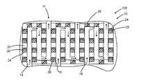
- FIG. 1illustrates a bipolar plate including a reactant gas flow field defined therein for use in a method according to one exemplary embodiment of the invention.
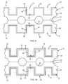
- FIG. 2illustrates a mask including a plurality of openings defined therein for placement over the bipolar plate illustrated in FIG. 1 according to one exemplary embodiment of the invention.
- FIG. 3illustrates a method according to one exemplary embodiment of the invention wherein the mask is placed over the bipolar plate so that the openings in the mask overlie portions of lands and channels on the bipolar plate.
- FIG. 4illustrates a method according to one exemplary embodiment of the invention including depositing a low contact resistance coating through the openings in the mask of FIG. 3 .
- FIG. 5illustrates an alternative exemplary embodiment of a mask including discrete openings patterned after the location of lands in a bipolar plate for use in a method according to one exemplary embodiment of the invention.
- FIG. 6illustrates a method according to one exemplary embodiment of the invention wherein the mask having discrete openings is placed over the bipolar plate so that the discrete openings are aligned with the lands on the bipolar plate.
- FIG. 7illustrates a method according to one exemplary embodiment of the invention including depositing a low contact resistance material through the openings in the mask and onto a plurality of spaced apart locations on the lands of the bipolar plate.
- FIG. 10illustrates a method of depositing a low contact coating over the hydrophilic coating and over the lands and channels of a bipolar plate according to one exemplary embodiment of the invention.
- FIG. 11illustrates a method including depositing a hydrophilic coating over the lands and channel of a bipolar plate and thereafter depositing a low contact resistance coating over only the land portions of the bipolar plate according to one exemplary embodiment of the invention.
- FIG. 10illustrates a method of depositing a low contact resistant coating over the hydrophilic coating and over the lands and channels of a bipolar plate according to one exemplary embodiment of the invention.
- FIG. 11illustrates a method including depositing a hydrophilic coating over the lands and channel of a bipolar plate and thereafter depositing a low contact resistant coating over only the land portions of the bipolar plate according to one exemplary embodiment of the invention.
- FIG. 12illustrates a method of depositing a hydrophilic coating over the channel portion of a bipolar plate and depositing a low contact resistance coating over the land portion and not into the channel portion according to one exemplary embodiment of the invention.
- FIG. 13illustrates a portion of a fuel cell stack including a plurality of bipolar plates including a low contact resistance coating deposited over a plurality of locations on the bipolar plate including a plurality of locations on the lands, leaving a plurality of locations on the lands uncoated by the low contact resistance coating according to one exemplary embodiment of the invention.
- one exemplary embodiment of the inventionmay include a method including providing a bipolar plate 10 for use in a fuel cell.
- the bipolar plate 10may include a reactant gas flow field 11 defined therein.
- the bipolar platemay include a first face 12 and one or more reactant gas flow channels 14 , 16 , 18 defined in the first face 12 at least in part by a plurality of lands 20 .
- the arrows in FIG. 1indicate the direction in one embodiment, that a reactant gas may flow through one of the channels 14 , 16 , 18 .
- a maskmay be provided, including a plurality of openings 24 defined therein.
- the openings 24may be in the form of elongated slots which may span the area of the lands 20 defining the reactant gas flow path 11 in the bipolar plate 10 .
- the mask 22may be provided over the bipolar plate so that the elongated slot openings 24 span a plurality of lands 20 and at least one of the channels 14 , 16 or 18 .
- a low contact resistance material or coatingsuch as, but not limited to, gold, palladium, platinum, iridium, ruthenium, or mixtures thereof may be deposited through the openings 24 in the mask 22 and onto a plurality of portions of the lands and into portions of the channels 14 , 16 or 18 .
- the low contact resistance material 26is deposited at a plurality of locations on the lands and a plurality of locations on the channels.
- a plurality of locations on the lands and a plurality of locations on the channelsare left uncovered by the low contact resistance material 26 .
- the cost of manufacturing a bipolar plate with a low contact resistance coating thereonmay be drastically reduced because much less of the low contact resistance material 26 is deposited on the bipolar plate 10 in comparison to the prior art method which covered the entire face of the bipolar plate.
- the lands 20are not completely covered by the low contact resistance material 26 , no significant change in fuel cell performance was observed.
- the low contact resistance material or coatingmay be deposited only overlying the active area of the fuel cell (the area directly underlying or overlying the anode or cathode catalyst) to further reduce the amount of the low contact resistance material needed to be applied to the bipolar plate 10 .
- the methodmay include depositing strips of low contact resistance material 26 in a direction that is not generally perpendicular to the longitudinal direction of the lands and may be skewed therefrom.
- an alternative mask 22may be provided, including discrete openings 24 defined therein and arranged to be aligned with only the lands 20 of the bipolar plate 10 and not the channels 14 , 16 or 18 .
- the mask 22 of FIG. 5may be placed over the bipolar plate 10 so that the discrete openings 24 align with the lands 20 of the bipolar plate, and not with the channels 14 , 16 or 18 .
- a low contact resistance material 26may be deposited through the discrete openings 24 and onto the lands 20 , so that substantially none of the low contact resistance material is deposited into the channels 14 , 16 or 20 . Depositing the low contact resistance material 26 only on the land portions, leaving portions of the land uncoated, drastically reduces the amount of the low contact resistance material needed on the bipolar plate.
- an alternative mask 122may be provided and includes a plurality of openings 114 , 116 , 118 formed therein and constructed and arranged to be aligned with the channels 14 , 16 and 18 of the bipolar plate.
- the mask 122may be placed over the bipolar plate and a hydrophilic coating may be deposited through the openings 114 , 116 and 118 so that the hydrophilic coating is deposited substantially only in the channels 14 , 16 or 18 of the bipolar plate and not onto the lands 20 .
- the hydrophilic coating deposited only in the channels 14 , 16 or 18may improve water management of a fuel cell stack, reducing the likelihood of water droplets blocking reactant gas flow through the channels 14 , 16 or 18 formed in the bipolar plate 10 .
- a first coating 40which may be a hydrophilic material may be deposited over surfaces 12 , 12 ′ including the lands 20 , 20 ′ and channels 14 , 14 ′.
- the channel portions 14 , 14 ′may be defined by a lower wall or floor 34 and at least a first side wall 36 and optionally a second side wall 38 , 38 ′ respectively.
- the low contact resistance material 26may be selectively deposited over portions of the lands 20 , 20 ′ and channels 14 , 14 ′, leaving portions of the lands 20 , 20 ′ and channels 14 , 14 ′ uncoated by the low contact resistance material.
- the first coating 40may be deposited over the lands 20 , 20 ′ and channels 14 , 14 ′ of the bipolar plate and thereafter the low contact resistance material 26 , 26 ′ may be deposited substantially only over the lands 20 , 20 ′ without depositing any significant amount of the low contact resistance material 26 in the channels 14 , 14 ′.
- the first coating 40which may be a hydrophilic coating, may be deposited only in the channels 14 , 14 ′ and the low contact resistance material 26 , 26 ′ may be deposited substantially only over the lands 20 , 20 ′ and so that substantially no contact resistance material 26 is deposited in the channels 14 , 14 ′.
- substantially no hydrophilic coatingis deposited over the lands 20 , 20 ′.
- one exemplary embodiment of the inventionincludes a product 10 such as a fuel cell stack including a plurality of bipolar plates 10 having a low contact resistance material 26 selectively deposited over portions of lands 20 , 20 ′, leaving portions of the lands 20 , 20 ′ uncovered by the low contact resistance material 26 .
- the fuel cell stackmay include a soft goods portion 44 which may include a membrane 46 having a first face 48 and a second face 50 , a cathode electrode 52 may be deposited over the first face 48 of the membrane 46 and an anode electrode 58 may be deposited over the second face 50 of the membrane 46 .
- An anode side gas diffusion media layerwhich may have a microporous layer 56 thereon may be interposed between the anode catalyst layer 52 and the bipolar plate 10 .
- the low contact resistance material 26 over the lands 20 , 20 ′ of the bipolar plate 10contact the anode side gas diffusion media layer 54 .
- a cathode side gas diffusion media layer 60 having a microporous layer 62 thereonmay be interposed between the cathode catalyst layer 58 and a second bipolar plate 10 so that the low contact resistance coating 26 on the lands 20 contacts the cathode side gas diffusion media layer 60 .
- the bipolar plate 10may be made from a first substrate 28 and a second substrate 28 ′ which may be welded together to define coolant flow channels 32 for flowing cooling fluid through the center of the bipolar plate 10 to cool the same.
Landscapes
- Chemical & Material Sciences (AREA)
- Life Sciences & Earth Sciences (AREA)
- Engineering & Computer Science (AREA)
- Manufacturing & Machinery (AREA)
- Sustainable Development (AREA)
- Sustainable Energy (AREA)
- Chemical Kinetics & Catalysis (AREA)
- Electrochemistry (AREA)
- General Chemical & Material Sciences (AREA)
- Composite Materials (AREA)
- Fuel Cell (AREA)
- Inert Electrodes (AREA)
Abstract
Description
Claims (25)
Priority Applications (3)
| Application Number | Priority Date | Filing Date | Title |
|---|---|---|---|
| US12/122,162US8148035B2 (en) | 2008-05-16 | 2008-05-16 | Bipolar plate coating architecture for fuel cells and methods of making and using the same |
| DE102009020463.6ADE102009020463B4 (en) | 2008-05-16 | 2009-05-08 | Coating architecture for bipolar plates for fuel cells and method of manufacture |
| CNA200910139094XACN101582510A (en) | 2008-05-16 | 2009-05-15 | Bipolar plate containing architecture for fuel cell and method of making and using the same |
Applications Claiming Priority (1)
| Application Number | Priority Date | Filing Date | Title |
|---|---|---|---|
| US12/122,162US8148035B2 (en) | 2008-05-16 | 2008-05-16 | Bipolar plate coating architecture for fuel cells and methods of making and using the same |
Publications (2)
| Publication Number | Publication Date |
|---|---|
| US20090286118A1 US20090286118A1 (en) | 2009-11-19 |
| US8148035B2true US8148035B2 (en) | 2012-04-03 |
Family
ID=41268982
Family Applications (1)
| Application Number | Title | Priority Date | Filing Date |
|---|---|---|---|
| US12/122,162Expired - Fee RelatedUS8148035B2 (en) | 2008-05-16 | 2008-05-16 | Bipolar plate coating architecture for fuel cells and methods of making and using the same |
Country Status (3)
| Country | Link |
|---|---|
| US (1) | US8148035B2 (en) |
| CN (1) | CN101582510A (en) |
| DE (1) | DE102009020463B4 (en) |
Cited By (2)
| Publication number | Priority date | Publication date | Assignee | Title |
|---|---|---|---|---|
| US20100032306A1 (en)* | 2008-08-08 | 2010-02-11 | Gm Global Technology Operations, Inc. | Electrochemical deposition of conductive coatings on fuel cell bipolar plates |
| US20110143247A1 (en)* | 2009-12-15 | 2011-06-16 | Seong-Jin An | Fuel cell stack and fuel cell system including the same |
Families Citing this family (3)
| Publication number | Priority date | Publication date | Assignee | Title |
|---|---|---|---|---|
| ES2409454B1 (en)* | 2010-07-16 | 2014-05-12 | Consejo Superior De Investigaciones Científicas (Csic) | FUEL BATTERY PLATE WITH VARIOUS CHEMICAL REACTION AREAS. |
| JP7081307B2 (en)* | 2018-05-28 | 2022-06-07 | トヨタ紡織株式会社 | Fuel cell separator |
| DE102020133553A1 (en) | 2020-12-15 | 2022-06-15 | Schaeffler Technologies AG & Co. KG | Method of making a bipolar plate for an electrochemical cell and bipolar plate |
Citations (8)
| Publication number | Priority date | Publication date | Assignee | Title |
|---|---|---|---|---|
| US5776624A (en) | 1996-12-23 | 1998-07-07 | General Motors Corporation | Brazed bipolar plates for PEM fuel cells |
| US5942348A (en) | 1994-12-01 | 1999-08-24 | Siemens Aktiengesellschaft | Fuel cell with ceramic-coated bipolar plates and a process for producing the fuel cell |
| US6649031B1 (en) | 1999-10-08 | 2003-11-18 | Hybrid Power Generation Systems, Llc | Corrosion resistant coated fuel cell bipolar plate with filled-in fine scale porosities and method of making the same |
| US6852438B2 (en)* | 2000-05-26 | 2005-02-08 | Kabushiki Kaisha Riken | Embossed current collector separator for electrochemical fuel cell |
| US6866958B2 (en) | 2002-06-05 | 2005-03-15 | General Motors Corporation | Ultra-low loadings of Au for stainless steel bipolar plates |
| US20060093735A1 (en)* | 2004-11-01 | 2006-05-04 | Yang-Tse Cheng | Fuel cell water management enhancement method |
| US20060105222A1 (en)* | 2004-11-12 | 2006-05-18 | Abd Elhamid Mahmoud H | Hydrophilic surface modification of bipolar plate |
| CN101123313A (en) | 2006-08-09 | 2008-02-13 | 大同特殊钢株式会社 | Metal bipolar plate for fuel cell and fuel cell including the metal bipolar plate |
Family Cites Families (2)
| Publication number | Priority date | Publication date | Assignee | Title |
|---|---|---|---|---|
| DE10036272A1 (en)* | 2000-07-26 | 2002-02-07 | Daimler Chrysler Ag | Bipolar fuel cell plate forming gas tight connection between its main outer surfaces, includes distributed, conductive, corrosion-resistant surface clusters |
| US20080050643A1 (en)* | 2006-08-24 | 2008-02-28 | Gm Global Technology Operations, Inc. | Electrically conductive lands adhered to gas diffusion media and methods of making and using the same |
- 2008
- 2008-05-16USUS12/122,162patent/US8148035B2/ennot_activeExpired - Fee Related
- 2009
- 2009-05-08DEDE102009020463.6Apatent/DE102009020463B4/ennot_activeExpired - Fee Related
- 2009-05-15CNCNA200910139094XApatent/CN101582510A/enactivePending
Patent Citations (10)
| Publication number | Priority date | Publication date | Assignee | Title |
|---|---|---|---|---|
| US5942348A (en) | 1994-12-01 | 1999-08-24 | Siemens Aktiengesellschaft | Fuel cell with ceramic-coated bipolar plates and a process for producing the fuel cell |
| US5776624A (en) | 1996-12-23 | 1998-07-07 | General Motors Corporation | Brazed bipolar plates for PEM fuel cells |
| US6649031B1 (en) | 1999-10-08 | 2003-11-18 | Hybrid Power Generation Systems, Llc | Corrosion resistant coated fuel cell bipolar plate with filled-in fine scale porosities and method of making the same |
| US6852438B2 (en)* | 2000-05-26 | 2005-02-08 | Kabushiki Kaisha Riken | Embossed current collector separator for electrochemical fuel cell |
| US6866958B2 (en) | 2002-06-05 | 2005-03-15 | General Motors Corporation | Ultra-low loadings of Au for stainless steel bipolar plates |
| US20060093735A1 (en)* | 2004-11-01 | 2006-05-04 | Yang-Tse Cheng | Fuel cell water management enhancement method |
| US20060105222A1 (en)* | 2004-11-12 | 2006-05-18 | Abd Elhamid Mahmoud H | Hydrophilic surface modification of bipolar plate |
| CN101057350A (en) | 2004-11-12 | 2007-10-17 | 通用汽车公司 | Hydrophilic surface modification of bipolar plate |
| CN101123313A (en) | 2006-08-09 | 2008-02-13 | 大同特殊钢株式会社 | Metal bipolar plate for fuel cell and fuel cell including the metal bipolar plate |
| US20080038619A1 (en)* | 2006-08-09 | 2008-02-14 | Daido Tokushuko Kabushiki Kaisha | Metallic bipolar plate for fuel cells,and fuel cell comprising the same |
Cited By (4)
| Publication number | Priority date | Publication date | Assignee | Title |
|---|---|---|---|---|
| US20100032306A1 (en)* | 2008-08-08 | 2010-02-11 | Gm Global Technology Operations, Inc. | Electrochemical deposition of conductive coatings on fuel cell bipolar plates |
| US8246808B2 (en)* | 2008-08-08 | 2012-08-21 | GM Global Technology Operations LLC | Selective electrochemical deposition of conductive coatings on fuel cell bipolar plates |
| US20110143247A1 (en)* | 2009-12-15 | 2011-06-16 | Seong-Jin An | Fuel cell stack and fuel cell system including the same |
| US8945786B2 (en)* | 2009-12-15 | 2015-02-03 | Samsung Sdi Co., Ltd. | Fuel cell stack and fuel cell system including the same |
Also Published As
| Publication number | Publication date |
|---|---|
| US20090286118A1 (en) | 2009-11-19 |
| DE102009020463A1 (en) | 2009-12-10 |
| DE102009020463B4 (en) | 2014-12-04 |
| CN101582510A (en) | 2009-11-18 |
Similar Documents
| Publication | Publication Date | Title |
|---|---|---|
| JP5560728B2 (en) | Fuel cell | |
| JP4791253B2 (en) | Fuel cell separator plate coating | |
| KR102100053B1 (en) | Seperator for fuel cell | |
| JP6931055B2 (en) | Bipolar plate for fuel cells with improved flow distribution | |
| US6485857B2 (en) | Fuel cell hybrid flow field humidification zone | |
| US8148035B2 (en) | Bipolar plate coating architecture for fuel cells and methods of making and using the same | |
| KR101806620B1 (en) | Fuel cell stack | |
| US20080050629A1 (en) | Apparatus and method for managing a flow of cooling media in a fuel cell stack | |
| US7419737B2 (en) | Fuel supply device for direct methanol fuel cells | |
| JP5139753B2 (en) | Fuel cell | |
| WO2013005300A1 (en) | Fuel cell | |
| JP2005174648A (en) | Fuel cell | |
| US20070254203A1 (en) | Fuel cell stack | |
| JP6272838B2 (en) | Bipolar plate for fuel cell | |
| US20090191351A1 (en) | Fuel cell bipolar plate with variable surface properties | |
| JP5808695B2 (en) | Fuel cell | |
| US7846607B2 (en) | Separator for fuel cell having channels for self-humidification | |
| US20100075199A1 (en) | Hydrophobic layer for a fuel cell | |
| US20170373327A1 (en) | Fuel cell system | |
| CN101432914B (en) | Stamped PEM fuel cell plate manufacturing | |
| US7816050B2 (en) | Unit cell header flow enhancement | |
| KR100778584B1 (en) | Fuel Cell with Multilayer Separator | |
| US20060228616A1 (en) | Fluid channel structure for polar plate of fuel cell | |
| JP2006066172A (en) | Fuel cell | |
| JP2012038569A (en) | Fuel cell |
Legal Events
| Date | Code | Title | Description |
|---|---|---|---|
| AS | Assignment | Owner name:GM GLOBAL TECHNOLOGY OPERATIONS, INC., MICHIGAN Free format text:ASSIGNMENT OF ASSIGNORS INTEREST;ASSIGNORS:DADHEECH, GAYATRI VYAS;MIKHAIL, YOUSSEF M.;ABD ELHAMID, MAHMOUD H.;REEL/FRAME:020999/0768 Effective date:20080508 | |
| AS | Assignment | Owner name:UNITED STATES DEPARTMENT OF THE TREASURY,DISTRICT Free format text:SECURITY AGREEMENT;ASSIGNOR:GM GLOBAL TECHNOLOGY OPERATIONS, INC.;REEL/FRAME:022201/0448 Effective date:20081231 Owner name:UNITED STATES DEPARTMENT OF THE TREASURY, DISTRICT Free format text:SECURITY AGREEMENT;ASSIGNOR:GM GLOBAL TECHNOLOGY OPERATIONS, INC.;REEL/FRAME:022201/0448 Effective date:20081231 | |
| AS | Assignment | Owner name:CITICORP USA, INC. AS AGENT FOR BANK PRIORITY SECU Free format text:SECURITY AGREEMENT;ASSIGNOR:GM GLOBAL TECHNOLOGY OPERATIONS, INC.;REEL/FRAME:022554/0538 Effective date:20090409 Owner name:CITICORP USA, INC. AS AGENT FOR HEDGE PRIORITY SEC Free format text:SECURITY AGREEMENT;ASSIGNOR:GM GLOBAL TECHNOLOGY OPERATIONS, INC.;REEL/FRAME:022554/0538 Effective date:20090409 | |
| AS | Assignment | Owner name:GM GLOBAL TECHNOLOGY OPERATIONS, INC., MICHIGAN Free format text:RELEASE BY SECURED PARTY;ASSIGNOR:UNITED STATES DEPARTMENT OF THE TREASURY;REEL/FRAME:023124/0670 Effective date:20090709 Owner name:GM GLOBAL TECHNOLOGY OPERATIONS, INC.,MICHIGAN Free format text:RELEASE BY SECURED PARTY;ASSIGNOR:UNITED STATES DEPARTMENT OF THE TREASURY;REEL/FRAME:023124/0670 Effective date:20090709 | |
| AS | Assignment | Owner name:GM GLOBAL TECHNOLOGY OPERATIONS, INC., MICHIGAN Free format text:RELEASE BY SECURED PARTY;ASSIGNORS:CITICORP USA, INC. AS AGENT FOR BANK PRIORITY SECURED PARTIES;CITICORP USA, INC. AS AGENT FOR HEDGE PRIORITY SECURED PARTIES;REEL/FRAME:023155/0880 Effective date:20090814 Owner name:GM GLOBAL TECHNOLOGY OPERATIONS, INC.,MICHIGAN Free format text:RELEASE BY SECURED PARTY;ASSIGNORS:CITICORP USA, INC. AS AGENT FOR BANK PRIORITY SECURED PARTIES;CITICORP USA, INC. AS AGENT FOR HEDGE PRIORITY SECURED PARTIES;REEL/FRAME:023155/0880 Effective date:20090814 | |
| AS | Assignment | Owner name:UNITED STATES DEPARTMENT OF THE TREASURY, DISTRICT Free format text:SECURITY AGREEMENT;ASSIGNOR:GM GLOBAL TECHNOLOGY OPERATIONS, INC.;REEL/FRAME:023156/0215 Effective date:20090710 Owner name:UNITED STATES DEPARTMENT OF THE TREASURY,DISTRICT Free format text:SECURITY AGREEMENT;ASSIGNOR:GM GLOBAL TECHNOLOGY OPERATIONS, INC.;REEL/FRAME:023156/0215 Effective date:20090710 | |
| AS | Assignment | Owner name:UAW RETIREE MEDICAL BENEFITS TRUST, MICHIGAN Free format text:SECURITY AGREEMENT;ASSIGNOR:GM GLOBAL TECHNOLOGY OPERATIONS, INC.;REEL/FRAME:023162/0187 Effective date:20090710 Owner name:UAW RETIREE MEDICAL BENEFITS TRUST,MICHIGAN Free format text:SECURITY AGREEMENT;ASSIGNOR:GM GLOBAL TECHNOLOGY OPERATIONS, INC.;REEL/FRAME:023162/0187 Effective date:20090710 | |
| AS | Assignment | Owner name:GM GLOBAL TECHNOLOGY OPERATIONS, INC., MICHIGAN Free format text:RELEASE BY SECURED PARTY;ASSIGNOR:UNITED STATES DEPARTMENT OF THE TREASURY;REEL/FRAME:025245/0780 Effective date:20100420 | |
| AS | Assignment | Owner name:GM GLOBAL TECHNOLOGY OPERATIONS, INC., MICHIGAN Free format text:RELEASE BY SECURED PARTY;ASSIGNOR:UAW RETIREE MEDICAL BENEFITS TRUST;REEL/FRAME:025315/0001 Effective date:20101026 | |
| AS | Assignment | Owner name:WILMINGTON TRUST COMPANY, DELAWARE Free format text:SECURITY AGREEMENT;ASSIGNOR:GM GLOBAL TECHNOLOGY OPERATIONS, INC.;REEL/FRAME:025324/0475 Effective date:20101027 | |
| AS | Assignment | Owner name:GM GLOBAL TECHNOLOGY OPERATIONS LLC, MICHIGAN Free format text:CHANGE OF NAME;ASSIGNOR:GM GLOBAL TECHNOLOGY OPERATIONS, INC.;REEL/FRAME:025781/0211 Effective date:20101202 | |
| FEPP | Fee payment procedure | Free format text:PAYOR NUMBER ASSIGNED (ORIGINAL EVENT CODE: ASPN); ENTITY STATUS OF PATENT OWNER: LARGE ENTITY | |
| STCF | Information on status: patent grant | Free format text:PATENTED CASE | |
| AS | Assignment | Owner name:GM GLOBAL TECHNOLOGY OPERATIONS LLC, MICHIGAN Free format text:RELEASE BY SECURED PARTY;ASSIGNOR:WILMINGTON TRUST COMPANY;REEL/FRAME:034384/0758 Effective date:20141017 | |
| FPAY | Fee payment | Year of fee payment:4 | |
| FEPP | Fee payment procedure | Free format text:MAINTENANCE FEE REMINDER MAILED (ORIGINAL EVENT CODE: REM.); ENTITY STATUS OF PATENT OWNER: LARGE ENTITY | |
| LAPS | Lapse for failure to pay maintenance fees | Free format text:PATENT EXPIRED FOR FAILURE TO PAY MAINTENANCE FEES (ORIGINAL EVENT CODE: EXP.); ENTITY STATUS OF PATENT OWNER: LARGE ENTITY | |
| STCH | Information on status: patent discontinuation | Free format text:PATENT EXPIRED DUE TO NONPAYMENT OF MAINTENANCE FEES UNDER 37 CFR 1.362 | |
| FP | Lapsed due to failure to pay maintenance fee | Effective date:20200403 |