US8147599B2 - Apparatuses and methods for storing and/or filtering a substance - Google Patents
Apparatuses and methods for storing and/or filtering a substanceDownload PDFInfo
- Publication number
- US8147599B2 US8147599B2US12/857,515US85751510AUS8147599B2US 8147599 B2US8147599 B2US 8147599B2US 85751510 AUS85751510 AUS 85751510AUS 8147599 B2US8147599 B2US 8147599B2
- Authority
- US
- United States
- Prior art keywords
- layer
- substance
- sorption material
- sorption
- layers
- Prior art date
- Legal status (The legal status is an assumption and is not a legal conclusion. Google has not performed a legal analysis and makes no representation as to the accuracy of the status listed.)
- Expired - Fee Related
Links
- 239000000126substanceSubstances0.000titleclaimsabstractdescription215
- 238000000034methodMethods0.000titleabstractdescription37
- 238000001914filtrationMethods0.000titledescription13
- 238000001179sorption measurementMethods0.000claimsabstractdescription348
- 239000000463materialSubstances0.000claimsabstractdescription102
- 238000011068loading methodMethods0.000claimsabstractdescription37
- 238000010521absorption reactionMethods0.000claimsabstract6
- 239000012528membraneSubstances0.000claimsdescription45
- 238000012546transferMethods0.000claimsdescription25
- OKTJSMMVPCPJKN-UHFFFAOYSA-NCarbonChemical compound[C]OKTJSMMVPCPJKN-UHFFFAOYSA-N0.000claimsdescription17
- 239000000446fuelSubstances0.000claimsdescription14
- 229910021389grapheneInorganic materials0.000claimsdescription8
- 229910052582BNInorganic materials0.000claimsdescription6
- PZNSFCLAULLKQX-UHFFFAOYSA-NBoron nitrideChemical compoundN#BPZNSFCLAULLKQX-UHFFFAOYSA-N0.000claimsdescription6
- 230000003247decreasing effectEffects0.000abstractdescription2
- VNWKTOKETHGBQD-UHFFFAOYSA-NmethaneChemical compoundCVNWKTOKETHGBQD-UHFFFAOYSA-N0.000description59
- 150000001875compoundsChemical class0.000description33
- 238000005516engineering processMethods0.000description27
- 239000007789gasSubstances0.000description25
- 229910052739hydrogenInorganic materials0.000description24
- 239000001257hydrogenSubstances0.000description24
- UFHFLCQGNIYNRP-UHFFFAOYSA-NHydrogenChemical compound[H][H]UFHFLCQGNIYNRP-UHFFFAOYSA-N0.000description22
- 239000003054catalystSubstances0.000description21
- 238000006243chemical reactionMethods0.000description18
- 239000002071nanotubeSubstances0.000description13
- CURLTUGMZLYLDI-UHFFFAOYSA-NCarbon dioxideChemical compoundO=C=OCURLTUGMZLYLDI-UHFFFAOYSA-N0.000description12
- 229930195733hydrocarbonNatural products0.000description12
- 150000002430hydrocarbonsChemical class0.000description12
- 239000006227byproductSubstances0.000description11
- 239000007788liquidSubstances0.000description10
- OKKJLVBELUTLKV-UHFFFAOYSA-NMethanolChemical compoundOCOKKJLVBELUTLKV-UHFFFAOYSA-N0.000description9
- XEEYBQQBJWHFJM-UHFFFAOYSA-NIronChemical compound[Fe]XEEYBQQBJWHFJM-UHFFFAOYSA-N0.000description8
- 125000004429atomChemical group0.000description8
- -1carbonized tissuesSubstances0.000description8
- 239000000203mixtureSubstances0.000description8
- 238000003860storageMethods0.000description8
- 238000004519manufacturing processMethods0.000description7
- XLYOFNOQVPJJNP-UHFFFAOYSA-NwaterSubstancesOXLYOFNOQVPJJNP-UHFFFAOYSA-N0.000description7
- XKRFYHLGVUSROY-UHFFFAOYSA-NArgonChemical compound[Ar]XKRFYHLGVUSROY-UHFFFAOYSA-N0.000description6
- PXHVJJICTQNCMI-UHFFFAOYSA-NNickelChemical compound[Ni]PXHVJJICTQNCMI-UHFFFAOYSA-N0.000description6
- 229910002092carbon dioxideInorganic materials0.000description6
- 239000001569carbon dioxideSubstances0.000description6
- 239000013078crystalSubstances0.000description6
- 238000010438heat treatmentMethods0.000description6
- 239000003345natural gasSubstances0.000description6
- 230000008569processEffects0.000description6
- 239000000047productSubstances0.000description6
- 239000000376reactantSubstances0.000description6
- RYGMFSIKBFXOCR-UHFFFAOYSA-NCopperChemical compound[Cu]RYGMFSIKBFXOCR-UHFFFAOYSA-N0.000description5
- RTAQQCXQSZGOHL-UHFFFAOYSA-NTitaniumChemical compound[Ti]RTAQQCXQSZGOHL-UHFFFAOYSA-N0.000description5
- 230000008901benefitEffects0.000description5
- 229910052799carbonInorganic materials0.000description5
- 239000010949copperSubstances0.000description5
- 238000001228spectrumMethods0.000description5
- 239000000758substrateSubstances0.000description5
- 239000010936titaniumSubstances0.000description5
- IJGRMHOSHXDMSA-UHFFFAOYSA-NAtomic nitrogenChemical compoundN#NIJGRMHOSHXDMSA-UHFFFAOYSA-N0.000description4
- 239000004215Carbon black (E152)Substances0.000description4
- 229910052802copperInorganic materials0.000description4
- 238000010586diagramMethods0.000description4
- 238000005868electrolysis reactionMethods0.000description4
- 239000012530fluidSubstances0.000description4
- 239000003502gasolineSubstances0.000description4
- 229910002804graphiteInorganic materials0.000description4
- 239000010439graphiteSubstances0.000description4
- 229910052742ironInorganic materials0.000description4
- 229910052719titaniumInorganic materials0.000description4
- UGFAIRIUMAVXCW-UHFFFAOYSA-NCarbon monoxideChemical compound[O+]#[C-]UGFAIRIUMAVXCW-UHFFFAOYSA-N0.000description3
- PWHULOQIROXLJO-UHFFFAOYSA-NManganeseChemical compound[Mn]PWHULOQIROXLJO-UHFFFAOYSA-N0.000description3
- HCHKCACWOHOZIP-UHFFFAOYSA-NZincChemical compound[Zn]HCHKCACWOHOZIP-UHFFFAOYSA-N0.000description3
- 238000013459approachMethods0.000description3
- 229910052786argonInorganic materials0.000description3
- UORVGPXVDQYIDP-UHFFFAOYSA-NboraneChemical compoundBUORVGPXVDQYIDP-UHFFFAOYSA-N0.000description3
- 229910010277boron hydrideInorganic materials0.000description3
- 229910002091carbon monoxideInorganic materials0.000description3
- 229910001567cementiteInorganic materials0.000description3
- 238000002485combustion reactionMethods0.000description3
- 230000001276controlling effectEffects0.000description3
- 238000001816coolingMethods0.000description3
- 238000011161developmentMethods0.000description3
- 230000018109developmental processEffects0.000description3
- 150000002431hydrogenChemical class0.000description3
- 229910052748manganeseInorganic materials0.000description3
- 239000011572manganeseSubstances0.000description3
- 229910052987metal hydrideInorganic materials0.000description3
- 150000004681metal hydridesChemical class0.000description3
- 229910052759nickelInorganic materials0.000description3
- 230000006911nucleationEffects0.000description3
- 238000010899nucleationMethods0.000description3
- 229920000642polymerPolymers0.000description3
- 239000000243solutionSubstances0.000description3
- 125000006850spacer groupChemical group0.000description3
- 239000002699waste materialSubstances0.000description3
- 229910052725zincInorganic materials0.000description3
- 239000011701zincSubstances0.000description3
- ZOXJGFHDIHLPTG-UHFFFAOYSA-NBoronChemical compound[B]ZOXJGFHDIHLPTG-UHFFFAOYSA-N0.000description2
- VYZAMTAEIAYCRO-UHFFFAOYSA-NChromiumChemical compound[Cr]VYZAMTAEIAYCRO-UHFFFAOYSA-N0.000description2
- CBENFWSGALASAD-UHFFFAOYSA-NOzoneChemical compound[O-][O+]=OCBENFWSGALASAD-UHFFFAOYSA-N0.000description2
- KDLHZDBZIXYQEI-UHFFFAOYSA-NPalladiumChemical compound[Pd]KDLHZDBZIXYQEI-UHFFFAOYSA-N0.000description2
- QCWXUUIWCKQGHC-UHFFFAOYSA-NZirconiumChemical compound[Zr]QCWXUUIWCKQGHC-UHFFFAOYSA-N0.000description2
- MCMNRKCIXSYSNV-UHFFFAOYSA-NZirconium dioxideChemical compoundO=[Zr]=OMCMNRKCIXSYSNV-UHFFFAOYSA-N0.000description2
- 239000000853adhesiveSubstances0.000description2
- 230000001070adhesive effectEffects0.000description2
- 229910045601alloyInorganic materials0.000description2
- 239000000956alloySubstances0.000description2
- 230000015572biosynthetic processEffects0.000description2
- 229910052796boronInorganic materials0.000description2
- 229910052804chromiumInorganic materials0.000description2
- 239000011651chromiumSubstances0.000description2
- 239000002131composite materialSubstances0.000description2
- 239000004020conductorSubstances0.000description2
- 239000003989dielectric materialSubstances0.000description2
- 238000009792diffusion processMethods0.000description2
- 230000005611electricityEffects0.000description2
- 229910052757nitrogenInorganic materials0.000description2
- 235000015097nutrientsNutrition0.000description2
- 229920000728polyesterPolymers0.000description2
- 230000002787reinforcementEffects0.000description2
- 229910052727yttriumInorganic materials0.000description2
- VWQVUPCCIRVNHF-UHFFFAOYSA-Nyttrium atomChemical compound[Y]VWQVUPCCIRVNHF-UHFFFAOYSA-N0.000description2
- 229910052726zirconiumInorganic materials0.000description2
- CHJAYYWUZLWNSQ-UHFFFAOYSA-N1-chloro-1,2,2-trifluoroethene;etheneChemical groupC=C.FC(F)=C(F)ClCHJAYYWUZLWNSQ-UHFFFAOYSA-N0.000description1
- 229910000881Cu alloyInorganic materials0.000description1
- 229920001780ECTFEPolymers0.000description1
- 229910000640Fe alloyInorganic materials0.000description1
- 229920000877Melamine resinPolymers0.000description1
- 241001465754MetazoaSpecies0.000description1
- 229910000934Monel 400Inorganic materials0.000description1
- 239000002033PVDF binderSubstances0.000description1
- 229910021124PdAgInorganic materials0.000description1
- 229910000691Re alloyInorganic materials0.000description1
- 229910001069Ti alloyInorganic materials0.000description1
- 229920003230addition polyimidePolymers0.000description1
- UQZIWOQVLUASCR-UHFFFAOYSA-Nalumane;titaniumChemical compound[AlH3].[Ti]UQZIWOQVLUASCR-UHFFFAOYSA-N0.000description1
- 229910052782aluminiumInorganic materials0.000description1
- XAGFODPZIPBFFR-UHFFFAOYSA-NaluminiumChemical compound[Al]XAGFODPZIPBFFR-UHFFFAOYSA-N0.000description1
- 125000003118aryl groupChemical group0.000description1
- QVGXLLKOCUKJST-UHFFFAOYSA-Natomic oxygenChemical compound[O]QVGXLLKOCUKJST-UHFFFAOYSA-N0.000description1
- 239000003990capacitorSubstances0.000description1
- 230000003197catalytic effectEffects0.000description1
- 239000000919ceramicSubstances0.000description1
- 230000008859changeEffects0.000description1
- OANFWJQPUHQWDL-UHFFFAOYSA-Ncopper iron manganese nickelChemical compound[Mn].[Fe].[Ni].[Cu]OANFWJQPUHQWDL-UHFFFAOYSA-N0.000description1
- 238000000151depositionMethods0.000description1
- 238000001514detection methodMethods0.000description1
- ZOCHARZZJNPSEU-UHFFFAOYSA-NdiboronChemical compoundB#BZOCHARZZJNPSEU-UHFFFAOYSA-N0.000description1
- QDOXWKRWXJOMAK-UHFFFAOYSA-Ndichromium trioxideChemical compoundO=[Cr]O[Cr]=OQDOXWKRWXJOMAK-UHFFFAOYSA-N0.000description1
- 239000002283diesel fuelSubstances0.000description1
- KPUWHANPEXNPJT-UHFFFAOYSA-NdisiloxaneChemical class[SiH3]O[SiH3]KPUWHANPEXNPJT-UHFFFAOYSA-N0.000description1
- 239000000428dustSubstances0.000description1
- 239000004744fabricSubstances0.000description1
- 239000000835fiberSubstances0.000description1
- 239000004931filters and membranesSubstances0.000description1
- 239000011888foilSubstances0.000description1
- IVJISJACKSSFGE-UHFFFAOYSA-Nformaldehyde;1,3,5-triazine-2,4,6-triamineChemical compoundO=C.NC1=NC(N)=NC(N)=N1IVJISJACKSSFGE-UHFFFAOYSA-N0.000description1
- SLGWESQGEUXWJQ-UHFFFAOYSA-Nformaldehyde;phenolChemical compoundO=C.OC1=CC=CC=C1SLGWESQGEUXWJQ-UHFFFAOYSA-N0.000description1
- 238000003306harvestingMethods0.000description1
- 229910001385heavy metalInorganic materials0.000description1
- 150000004678hydridesChemical class0.000description1
- 238000002347injectionMethods0.000description1
- 239000007924injectionSubstances0.000description1
- 229910052500inorganic mineralInorganic materials0.000description1
- 238000009413insulationMethods0.000description1
- 230000001678irradiating effectEffects0.000description1
- 229910000103lithium hydrideInorganic materials0.000description1
- 229910012375magnesium hydrideInorganic materials0.000description1
- WPBNNNQJVZRUHP-UHFFFAOYSA-Lmanganese(2+);methyl n-[[2-(methoxycarbonylcarbamothioylamino)phenyl]carbamothioyl]carbamate;n-[2-(sulfidocarbothioylamino)ethyl]carbamodithioateChemical compound[Mn+2].[S-]C(=S)NCCNC([S-])=S.COC(=O)NC(=S)NC1=CC=CC=C1NC(=S)NC(=O)OCWPBNNNQJVZRUHP-UHFFFAOYSA-L0.000description1
- 230000007246mechanismEffects0.000description1
- 229910052751metalInorganic materials0.000description1
- 239000002184metalSubstances0.000description1
- 150000002739metalsChemical class0.000description1
- NMJORVOYSJLJGU-UHFFFAOYSA-Nmethane clathrateChemical compoundC.C.C.C.O.O.O.O.O.O.O.O.O.O.O.O.O.O.O.O.O.O.O.O.O.O.ONMJORVOYSJLJGU-UHFFFAOYSA-N0.000description1
- 239000010445micaSubstances0.000description1
- 229910052618mica groupInorganic materials0.000description1
- 239000011707mineralSubstances0.000description1
- 238000002156mixingMethods0.000description1
- 238000012986modificationMethods0.000description1
- 230000004048modificationEffects0.000description1
- 239000002086nanomaterialSubstances0.000description1
- 239000002073nanorodSubstances0.000description1
- 239000001301oxygenSubstances0.000description1
- 229910052760oxygenInorganic materials0.000description1
- 229910052763palladiumInorganic materials0.000description1
- 239000002245particleSubstances0.000description1
- 239000013618particulate matterSubstances0.000description1
- 230000002093peripheral effectEffects0.000description1
- 230000035699permeabilityEffects0.000description1
- 229920001568phenolic resinPolymers0.000description1
- 229920001601polyetherimidePolymers0.000description1
- 229920000139polyethylene terephthalatePolymers0.000description1
- 239000005020polyethylene terephthalateSubstances0.000description1
- 229920000098polyolefinPolymers0.000description1
- 229920001296polysiloxanePolymers0.000description1
- 229920002981polyvinylidene fluoridePolymers0.000description1
- 238000005086pumpingMethods0.000description1
- 230000005855radiationEffects0.000description1
- 229910052761rare earth metalInorganic materials0.000description1
- 150000002910rare earth metalsChemical class0.000description1
- 230000008929regenerationEffects0.000description1
- 238000011069regeneration methodMethods0.000description1
- 230000001105regulatory effectEffects0.000description1
- 230000001846repelling effectEffects0.000description1
- WUAPFZMCVAUBPE-UHFFFAOYSA-Nrhenium atomChemical compound[Re]WUAPFZMCVAUBPE-UHFFFAOYSA-N0.000description1
- 229920006395saturated elastomerPolymers0.000description1
- 238000000926separation methodMethods0.000description1
- 239000010935stainless steelSubstances0.000description1
- 229910001220stainless steelInorganic materials0.000description1
- 239000011232storage materialSubstances0.000description1
- 239000002470thermal conductorSubstances0.000description1
- 229920001169thermoplasticPolymers0.000description1
- 229920001187thermosetting polymerPolymers0.000description1
- 239000004416thermosoftening plasticSubstances0.000description1
- 239000010409thin filmSubstances0.000description1
- 229910000048titanium hydrideInorganic materials0.000description1
- 230000007704transitionEffects0.000description1
- 229910052723transition metalInorganic materials0.000description1
- 150000003624transition metalsChemical class0.000description1
- MTPVUVINMAGMJL-UHFFFAOYSA-Ntrimethyl(1,1,2,2,2-pentafluoroethyl)silaneChemical compoundC[Si](C)(C)C(F)(F)C(F)(F)FMTPVUVINMAGMJL-UHFFFAOYSA-N0.000description1
- 229910052720vanadiumInorganic materials0.000description1
- GPPXJZIENCGNKB-UHFFFAOYSA-NvanadiumChemical compound[V]#[V]GPPXJZIENCGNKB-UHFFFAOYSA-N0.000description1
- 238000010792warmingMethods0.000description1
- 239000010457zeoliteSubstances0.000description1
Images


Classifications
- B—PERFORMING OPERATIONS; TRANSPORTING
- B01—PHYSICAL OR CHEMICAL PROCESSES OR APPARATUS IN GENERAL
- B01D—SEPARATION
- B01D53/00—Separation of gases or vapours; Recovering vapours of volatile solvents from gases; Chemical or biological purification of waste gases, e.g. engine exhaust gases, smoke, fumes, flue gases, aerosols
- B01D53/34—Chemical or biological purification of waste gases
- B01D53/92—Chemical or biological purification of waste gases of engine exhaust gases
- B01D53/94—Chemical or biological purification of waste gases of engine exhaust gases by catalytic processes
- F—MECHANICAL ENGINEERING; LIGHTING; HEATING; WEAPONS; BLASTING
- F17—STORING OR DISTRIBUTING GASES OR LIQUIDS
- F17C—VESSELS FOR CONTAINING OR STORING COMPRESSED, LIQUEFIED OR SOLIDIFIED GASES; FIXED-CAPACITY GAS-HOLDERS; FILLING VESSELS WITH, OR DISCHARGING FROM VESSELS, COMPRESSED, LIQUEFIED, OR SOLIDIFIED GASES
- F17C11/00—Use of gas-solvents or gas-sorbents in vessels
- F17C11/005—Use of gas-solvents or gas-sorbents in vessels for hydrogen
- B—PERFORMING OPERATIONS; TRANSPORTING
- B32—LAYERED PRODUCTS
- B32B—LAYERED PRODUCTS, i.e. PRODUCTS BUILT-UP OF STRATA OF FLAT OR NON-FLAT, e.g. CELLULAR OR HONEYCOMB, FORM
- B32B3/00—Layered products comprising a layer with external or internal discontinuities or unevennesses, or a layer of non-planar shape; Layered products comprising a layer having particular features of form
- B32B3/10—Layered products comprising a layer with external or internal discontinuities or unevennesses, or a layer of non-planar shape; Layered products comprising a layer having particular features of form characterised by a discontinuous layer, i.e. formed of separate pieces of material
- B32B3/12—Layered products comprising a layer with external or internal discontinuities or unevennesses, or a layer of non-planar shape; Layered products comprising a layer having particular features of form characterised by a discontinuous layer, i.e. formed of separate pieces of material characterised by a layer of regularly- arranged cells, e.g. a honeycomb structure
- B—PERFORMING OPERATIONS; TRANSPORTING
- B32—LAYERED PRODUCTS
- B32B—LAYERED PRODUCTS, i.e. PRODUCTS BUILT-UP OF STRATA OF FLAT OR NON-FLAT, e.g. CELLULAR OR HONEYCOMB, FORM
- B32B9/00—Layered products comprising a layer of a particular substance not covered by groups B32B11/00 - B32B29/00
- B32B9/005—Layered products comprising a layer of a particular substance not covered by groups B32B11/00 - B32B29/00 comprising one layer of ceramic material, e.g. porcelain, ceramic tile
- B32B9/007—Layered products comprising a layer of a particular substance not covered by groups B32B11/00 - B32B29/00 comprising one layer of ceramic material, e.g. porcelain, ceramic tile comprising carbon, e.g. graphite, composite carbon
- F—MECHANICAL ENGINEERING; LIGHTING; HEATING; WEAPONS; BLASTING
- F17—STORING OR DISTRIBUTING GASES OR LIQUIDS
- F17C—VESSELS FOR CONTAINING OR STORING COMPRESSED, LIQUEFIED OR SOLIDIFIED GASES; FIXED-CAPACITY GAS-HOLDERS; FILLING VESSELS WITH, OR DISCHARGING FROM VESSELS, COMPRESSED, LIQUEFIED, OR SOLIDIFIED GASES
- F17C11/00—Use of gas-solvents or gas-sorbents in vessels
- F17C11/007—Use of gas-solvents or gas-sorbents in vessels for hydrocarbon gases, such as methane or natural gas, propane, butane or mixtures thereof [LPG]
- B—PERFORMING OPERATIONS; TRANSPORTING
- B01—PHYSICAL OR CHEMICAL PROCESSES OR APPARATUS IN GENERAL
- B01D—SEPARATION
- B01D2259/00—Type of treatment
- B01D2259/40—Further details for adsorption processes and devices
- B01D2259/40083—Regeneration of adsorbents in processes other than pressure or temperature swing adsorption
- B01D2259/40088—Regeneration of adsorbents in processes other than pressure or temperature swing adsorption by heating
- Y—GENERAL TAGGING OF NEW TECHNOLOGICAL DEVELOPMENTS; GENERAL TAGGING OF CROSS-SECTIONAL TECHNOLOGIES SPANNING OVER SEVERAL SECTIONS OF THE IPC; TECHNICAL SUBJECTS COVERED BY FORMER USPC CROSS-REFERENCE ART COLLECTIONS [XRACs] AND DIGESTS
- Y02—TECHNOLOGIES OR APPLICATIONS FOR MITIGATION OR ADAPTATION AGAINST CLIMATE CHANGE
- Y02E—REDUCTION OF GREENHOUSE GAS [GHG] EMISSIONS, RELATED TO ENERGY GENERATION, TRANSMISSION OR DISTRIBUTION
- Y02E60/00—Enabling technologies; Technologies with a potential or indirect contribution to GHG emissions mitigation
- Y02E60/30—Hydrogen technology
- Y02E60/32—Hydrogen storage
- Y—GENERAL TAGGING OF NEW TECHNOLOGICAL DEVELOPMENTS; GENERAL TAGGING OF CROSS-SECTIONAL TECHNOLOGIES SPANNING OVER SEVERAL SECTIONS OF THE IPC; TECHNICAL SUBJECTS COVERED BY FORMER USPC CROSS-REFERENCE ART COLLECTIONS [XRACs] AND DIGESTS
- Y10—TECHNICAL SUBJECTS COVERED BY FORMER USPC
- Y10S—TECHNICAL SUBJECTS COVERED BY FORMER USPC CROSS-REFERENCE ART COLLECTIONS [XRACs] AND DIGESTS
- Y10S502/00—Catalyst, solid sorbent, or support therefor: product or process of making
- Y10S502/526—Sorbent for fluid storage, other than an alloy for hydrogen storage
- Y—GENERAL TAGGING OF NEW TECHNOLOGICAL DEVELOPMENTS; GENERAL TAGGING OF CROSS-SECTIONAL TECHNOLOGIES SPANNING OVER SEVERAL SECTIONS OF THE IPC; TECHNICAL SUBJECTS COVERED BY FORMER USPC CROSS-REFERENCE ART COLLECTIONS [XRACs] AND DIGESTS
- Y10—TECHNICAL SUBJECTS COVERED BY FORMER USPC
- Y10T—TECHNICAL SUBJECTS COVERED BY FORMER US CLASSIFICATION
- Y10T137/00—Fluid handling
- Y10T137/0318—Processes
- Y—GENERAL TAGGING OF NEW TECHNOLOGICAL DEVELOPMENTS; GENERAL TAGGING OF CROSS-SECTIONAL TECHNOLOGIES SPANNING OVER SEVERAL SECTIONS OF THE IPC; TECHNICAL SUBJECTS COVERED BY FORMER USPC CROSS-REFERENCE ART COLLECTIONS [XRACs] AND DIGESTS
- Y10—TECHNICAL SUBJECTS COVERED BY FORMER USPC
- Y10T—TECHNICAL SUBJECTS COVERED BY FORMER US CLASSIFICATION
- Y10T137/00—Fluid handling
- Y10T137/794—With means for separating solid material from the fluid
Definitions
- the present technologyrelates to the storage and/or filtration of a substance by an apparatus comprising a sorption media.
- Oil's byproductsfuel cars, ships, and planes, and in much of the world it is burned to produce electricity.
- oilis a very useful substance, the earth contains only a limited quantity, and the earth's inhabitants, both plants and animals, are harmed directly and indirectly when oil is extracted from the ground and when its byproducts are combusted for energy.
- peopleIn order to preserve the environment and meet the energy needs of a growing world population, people must substitute alternative substances in place of oil.
- hydrogen and methaneare gasses at room temperature and atmospheric pressure, and therefore far less dense than liquid hydrocarbons like gasoline and diesel. Consequently, hydrogen gas contains only about 0.01079 megajoules per liter (“MJ/l”) and methane gas contains only about 0.0378 MJ/l, while gasoline contains about 32 MJ/l and diesel contains about 38.6 MJ/l. If gasses like hydrogen and methane are to replace hydrocarbons on a world level, they must be able to be stored in a manner that compensates for their low energy densities by volume.
- a first approachis to store the gas at a very high pressure. While this method is useful for many applications, including transporting gasses through pipelines, it is infeasible for most typical applications because substantial energy is wasted compressing the gas. Also, a tank capable of withstanding high pressure is too heavy for most vehicles, planes, or other machines that might be fueled by the compressed gas.
- Another approachis to store the gas as a liquid or slush. This approach suffers from a number of drawbacks, including extensive storage costs. For example, like hydrogen, one of the most viable alternatives to oil, many gasses boil at very low temperatures, meaning they must be cryogenically stored, and cooling the gas to a liquid or slush and keeping it cooled would waste a substantial amount of energy.
- Hydrogen and other gassesmay also be stored at higher energy densities per volume as an absorbed substance or as a metal hydride.
- metal hydridesinclude rare earth metals and have energy densities per weight that are lower than hydrocarbons because of the heavy metals used for storage.
- materials that receive hydrogensuch as activated carbon granules, carbonized tissues, zeolites, and hydride particles, are poor thermal conductors, meaning that the rate at which these materials may be cooled to absorb a gas and the rate that these materials may be heated to release a gas are both limited. These materials may also degrade or produce dust and debris, which may contaminate released gas and clog delivery conduits, fittings, valves, and filters of a storage system.
- FIG. 1is schematic cross-sectional side view of a vessel for storing and/or filtering a substance configured in accordance with an embodiment of the technology.
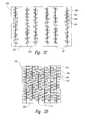
- FIG. 2Ais a blown-up schematic cross-sectional side view of parallel layers of a sorption media including surface structures configured in accordance with an embodiment of the technology.
- FIG. 2Bis a blown-up schematic cross-sectional side view of parallel layers of a sorption media including surface structures configured in accordance with an embodiment of the technology.
- FIG. 2Cis a blown-up schematic cross-sectional side view of parallel layers of a sorption media including surface structures configured in accordance with an embodiment of the technology.
- FIG. 2Dis a blown-up schematic cross-sectional side view of parallel layers of a sorption media including surface structures configured in accordance with an embodiment of the technology.
- FIG. 3is a flow diagram of a process for loading a substance in a sorption media in accordance with an embodiment of the technology.
- FIG. 4is a flow diagram of a process for unloading a substance from a sorption media in accordance with an embodiment of the technology.
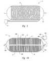
- FIG. 5is a side view of a vessel for storing and/or filtering a substance configured in accordance with an embodiment of the technology.
- FIG. 6Ais a schematic cross-sectional side view of a vessel for storing and/or filtering a substance configured in accordance with an embodiment of the technology.
- FIG. 6Bis a blown-up schematic cross-sectional side view of an area of a vessel for storing and/or filtering a substance configured in accordance with an embodiment of the technology.
- FIG. 6Cis a blown-up schematic cross-sectional side view of an area of a vessel for storing and/or filtering a substance configured in accordance with an embodiment of the technology.
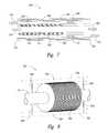
- FIG. 7is a schematic cross-sectional side view of an apparatus for filtering a substance configured in accordance with an embodiment of the technology.
- FIG. 8is an isometric view of an apparatus for filtering a substance configured in accordance with an embodiment of the technology.
- FIG. 9a schematic cross-sectional side view of a vessel for storing and/or filtering a substance and an associated system configured in accordance with an embodiment of the technology.
- a sorption mediacomprises parallel layers of a sorption material that are spaced apart by a certain distance or varying distances.
- a substanceis presented at an edge of the sorption media. The edge of the sorption media provides access to zones between layers of the sorption media.
- Heatmay be transferred away from the sorption media to facilitate and/or cause the sorption media to load (i.e. absorb and/or adsorb) molecules of the substance into the sorption media.
- a voltage of a first polaritymay be applied to the sorption media to facilitate and/or cause the sorption media to load molecules of the substance.
- a pressure experienced by the sorption mediamay be increased to facilitate and/or cause the sorption media to load molecules of the substance.
- the sorption mediaalso comprises surface structures that load the substance.
- a catalystfacilitates the loading of a substance into the sorption media. A substance can be unloaded from the sorption media by transferring heat to the sorption media, applying a voltage of an opposite polarity than the first polarity to the sorption media, and/or by reducing a pressure experienced by the sorption media.
- the sorption mediais encapsulated in a vessel. In some embodiments, the sorption media is configured in a tube. In some embodiments, the sorption media loads all molecules of a substance, while in other embodiments the sorption media loads only molecules of a specific compound or molecules of specific compounds of a substance. In some embodiments, the sorption media filters a substance. In some embodiments, the sorption media stores a substance. In some embodiments, a catalyst is applied to at least a portion of the sorption media to catalyze a chemical reaction between a substance loaded into the sorption media and another substance.
- FIG. 1is a schematic cross-sectional side view of a vessel 2 for storing and/or filtering a substance according to an embodiment of the technology.
- the vessel 2receives a substance, such as a gas, through a first port 10 , and the substance is passed through a perforated passageway 4 that runs through a sorption media 6 within the vessel 2 .
- a first valve 13 and a second valve 18may be opened or closed by varying degrees to control the amount of a substance entering or exiting the vessel 2 .
- the substanceis presented through perforations of the perforated passageway 4 to a first edge 15 of the sorption media 6 , which comprises parallel disk-shaped layers of a sorption material that loads (i.e., absorbs and/or adsorbs) the substance onto the layers of sorption material and in zones between the layers, reducing the volume of the substance that is loaded into the sorption media. Consequently, the vessel 2 can be configured to store a substance at a density much higher than the density at which the substance exists at atmospheric temperature and pressure.
- the vessel 2includes a second port 11 that can be used to expel the substance once it is released from the sorption media 6 .
- the vessel 2is configured so that only a particular compound of the substance is loaded by the sorption media 6 , and the remaining compounds of the substance are passed through the vessel 2 without being loaded. Consequently, the vessel 2 can also be configured to filter a substance.
- the sorption media 6 of the vessel 2comprises parallel layers of a sorption material, on and between which molecules of the substance are adsorbed and absorbed.
- Suitable materials for the parallel layersinclude graphene, graphite, boron nitride, ceramics, metals, or polymers, including various combinations and permutations of these materials.
- the materialhas a high availability for thermal transfer, which allows heat to be transferred throughout each layer and removed from each layer to facilitate the loading or unloading of a substance from the sorption media 6 .
- the materialis electrically conductive, and a voltage is applied across a layer of the parallel layers to facilitate the loading or unloading of a substance.
- Grapheneis an example of a suitable material for the sorption media 6 because it is electrically conductive and has a high availability for thermal transfer.
- each parallel layeris only one atom thick, while in other embodiments, some or all of the layers are greater than one atom thick.
- the thermal and electrical conductivities of a layer of the sorption media 6are adjusted by changing the thickness of the layer.
- the sorption media 6can be manufactured and configured into parallel layers using any of a number of techniques.
- the parallel layers of the sorption mediaare exfoliated from a single crystal.
- a single graphite crystalis grown and/or machined into a desired shape, such as a disc, and layers as thin as an atom are exfoliated off of the crystal.
- a holemay be bored through the graphite crystal before it is exfoliated, and a central substrate, such as the perforated passageway 4 , may hold the crystal in place while it is being exfoliated.
- 61/304,403which are incorporated herein by reference, describe suitable systems and methods for exfoliating single crystals to produce layers of sorption material as thin as one atom. Many other materials may be exfoliated using similar techniques, including compounds such as mica, zeolite-forming minerals, and boron nitride.
- the layers of the sorption media 6can also be formed by dehydrogenating a compound.
- energycan be applied to a hydrocarbon, such as methane, to dissociate the hydrocarbon, producing carbon and hydrogen. Electricity, for example, can be applied to the methane for a sufficient time to produce enough carbon for a layer of the sorption media.
- the resulting carboncan be deposited on a substrate or framed into a desired shape. These graphene deposits will self-organize into the layers of the sorption media, which may be configured on a substrate parallel to one another.
- FIG. 2Ashows a blown-up schematic cross-sectional side view of an area 200 of the sorption media 6 according to an embodiment of the technology.
- Various surface structures 20are applied on the surface of parallel layers 22 of the sorption media 6 . These surface structures 20 can include nano-tubes 20 a , nano-scrolls 20 b , and various other high surface nano structures, such as porous, exfoliated, carbonized tissues, rods 20 c , and flower-like structures 20 d .
- the surface structuresallow the sorption media to load more of a substance. In some embodiments, the surface structures allow the sorption media to load a particular compound of a substance. In some embodiments, the surface structures enable the sorption media to load and/or unload molecules of a substance more rapidly. In some embodiments, a particular type of surface structure is preferred over another surface structure. For example, in some embodiments, a nano-scroll may be preferred over a nano-tube.
- the nano-scrollmay be able to load and unload molecules of a substance more quickly than a nano-tube can because the nano-scroll may be able to load and unload multiple molecules of a substance at the same time while a nano-tube may only be able to load or unload one molecule at a time.
- a first type of surface structureloads a first compound and a second type of surface structure loads a second compound.
- the surface structures 20are composed of material that is electrically conductive and/or has a high availability for thermal transfer.
- the surface structuresare composed of carbon.
- the surface structurescan be configured on the layers of the sorption media 6 using a number of different techniques.
- the co-pending applications referenced abovedisclose a number of methods for configuring the surface structures 20 on surfaces of the parallel layers 22 .
- the surface structuresare epitaxially oriented by the lattice structure of the layer to which they are applied.
- the surface structuresare coated on a layer of the sorption material before an adjacent layer is configured next to the layer.
- a compoundis dehydrogenated on a layer of the sorption media 6 to form the surface structures 20 .
- the surface structuresact as spacers between parallel layers of the sorption media 6 , separating them by a desired distance.
- the distance between the parallel layersis only large enough to load a one-molecule-thick layer of a substance onto the surfaces of each of the parallel layers. In other embodiments, the distance is large enough to load molecules onto the surfaces of each of the parallel layers and at least a one-molecule-thick layer of a substance in a zone between the parallel layers, not on the surface of the layers. For example, molecules of a substance may be loaded onto a surface of the layers 22 of the sorption media 6 and into zones 204 between the layers 22 .
- the parallel layers of the sorption media 6are configured 90 ⁇ apart. Parallel layers of the sorption media 6 may be separated by 90 ⁇ , for example, to load natural gas.
- the layers of the sorption media 6are configured at a distance greater than 90 ⁇ or less than 90 ⁇ . For example, in some embodiments, the distance is 120 ⁇ or greater, and in other embodiments, the distance is less than 60 ⁇ .
- the distance between each layer of the sorption media 6is the same, while in other embodiments the distance between layers varies or is the same between only some of the parallel layers.
- some of the parallel layersmay be spaced a distance that enables the loading of molecules of a first compound, such as methane, and some of the parallel layers may be spaced a distance that enables the loading of molecules of a second compound, such as hydrogen.
- FIG. 2Bshows a blown-up schematic cross-sectional side view of the area 200 of the sorption media 6 according to another embodiment of the technology. Surface structures 20 are applied to the parallel layers 22 of the sorption media 6 .
- the parallel layers 22are spaced apart by different distances so that a first zone 210 is a different size from a size of a second zone 212 , which is also a different size from a size of a third zone 214 .
- the varied spacingmay allow for the preferential loading of different molecules into the various zones.
- the first zone 210may be configured to load methane and the second zone 212 may be configured to load hydrogen.
- FIG. 2Cshows a blown-up schematic cross-sectional side view of the area 200 of the sorption media 6 according to another embodiment of the technology.
- the layers 22 of the sorption media 6are spaced apart from one anther by varying distances so that the sorption media comprises zones of a first size, such as zone 222 , and zones of a second size, such as zone 224 .
- the surface structures 20vary in size. For example, in FIG. 2B , some nano-tubes 20 a are longer than other nano-tubes 20 a . In some embodiments, varying the size of the surface structures changes the rate at which they may load and unload a substance. In some embodiments, the sizes of the surface structures are increased or decreased to preferentially load a first compound over a second compound, or to vary the spacing between layers of the sorption media 6 .
- a zone between layers of sorption mediaincludes only a first type of surface structure.
- the third zone 214includes only nano-tubes.
- a zone between parallel layers of the sorption mediamay only include a particular type of surface structure to accommodate a specific compound.
- the third zone 214may include only nano-tubes 20 a because nano-tubes are able to load hydrogen at a higher density than nano-scrolls, and hydrogen is to be loaded into the third zone 214 .
- a zone between layers of sorption mediaincludes only two types of surface structures to accommodate a specific compound or compounds.
- the second zone 212may include only nano-scrolls 20 b and rods 20 c because nano-scrolls are able to load methane at a high density, and rods, although not able to load methane at a high density, are able to load and unload methane at a high rate. Therefore, the nano-scrolls 20 b and rods 20 c might compensate for each others' weakness in a particular application.
- all of the surface structures configured on layers of a sorption mediamay be of one type.
- a sorption mediamay include only nano-tubes for a particular application.
- the surface structures 20are oriented perpendicular to the layers 22 of the sorption media. In other embodiments, at least some of the surface structures 20 are not oriented perpendicular to the layers 22 of the sorption media and are instead oriented at a different angle. In FIG. 2C , the surface structures 20 are oriented at different angles from the layers 22 than 90-degrees. A surface structure may be oriented at a particular angle to increase the surface area of the surface structure, to increase the rate that molecules are loaded by the surface structure, to increase a loading density of the surface structure, to preferentially load a molecule of a particular compound, or for another reason.
- the surface structuresare composed of a different material from the material of the layer of sorption media 6 that it is attached to.
- FIG. 2Dshows a blown-up schematic cross-sectional side view of the area 200 of the sorption media 6 according to another embodiment of the technology.
- the parallel layers 22 of sorption mediaare composed of a first material, such as graphene.
- the surface structures 20are composed of a second material, such as boron nitride.
- a boron interfaceis applied to the graphene before the boron nitride is deposited to the parallel layers 22 .
- the surface structuresmay be composed of any of a number of different materials.
- the nano-tubes 20 a , nano-scrolls 20 b , rods 20 c , and/or flower-like structures 20 dare composed of boron hydride, diborane (B 2 H 6 ), sodium aluminum hydride, MgH 2 , LiH, titanium hydride, and/or another metal hydride or another compound.
- a boron hydride formation on a boron interfaceis endothermic, having a heat of formation that must be removed through the parallel layer to which it is applied.
- Hydrogenfor example, may be rapidly loaded to form a relatively unstable hydrogen storage because of the excellent thermal conductivity of boron hydride, which similarly allows for rapid unloading of the hydrogen.
- the distance between parallel layersmay be controlled using any of a number of techniques.
- surface structuresare applied on the surface of the layers of sorption media 6 and are configured to separate parallel layers of the sorption media 6 by a specific distance.
- the surface structures 20 from adjacent layerssuch as the surface structures in a zone 226 , contact one another, regulating the size of the zone 226 .
- the parallel layersare configured on a supporting substrate, such as the perforated passageway 4 , and like charges are applied to parallel layers, repelling the layers from one another to achieve a desired separation.
- the parallel layersmay also be separated by a desired distance by depositing atoms or compounds that act as spacers between the layers during manufacturing or while the layers are being configured on a substrate. For example, when a compound is dehydrogenated, separator atoms or molecules may be applied between each layer of the sorption media 6 that is produced.
- parallel layers of sorption media 6are formed from a host material that is heated, causing it to expand, and thus allowing separator atoms or compounds to be inserted between layers, which prevents the host material from contracting into the zones that have the separator atoms or compounds.
- the distance between two layers of the sorption media 6can also be controlled by a phase change in a layer or in a spacer between the two layers that induces a force that is sufficient to provide the work necessary to space the layers at a predetermined distance.
- the distance between layersmay be adjusted to provide structural support for the vessel 2 , to facilitate the transfer of heat to and from the layers, to allow light to pass between the layers, for catalytic purposes, and/or for dampening purposes.
- FIG. 3is a flow diagram of a process for loading a substance into the sorption media 6 .
- a substanceis presented at an edge of the sorption media.
- An edge of the sorption media 6includes an area that provides access to the zones between layers of the sorption media.
- the vessel 2 of FIG. 1comprises disk-shaped layers and the inside edge 15 of the sorption media 6 provides access to the zones between layers of the sorption media. Molecules of the substance may be loaded from the inside edge 15 of the sorption media 6 .
- molecules of the substanceare adsorbed onto surfaces of the layers of the sorption media 6 .
- the sorption media 6may load a substance when heat is transferred away from the sorption media 6 , when a voltage is applied to the sorption media 6 , and/or when a pressure experienced by the sorption media 6 is increased.
- a catalystfacilitates or causes the loading of a substance.
- molecules of the substanceare adsorbed onto the surface of surface structures that are configured on layers of the sorption media 6 .
- molecules of the substancemay be adsorbed onto the surface of a nano-rod that is configured on a surface of a layer of the sorption media.
- molecules of the substanceare absorbed into the surface structures.
- molecules of the substancemay be absorbed into a nano-tube that is located on a surface of a layer of the sorption media 6 .
- molecules of the substanceare absorbed into zones between layers of the sorption media 6 .
- molecules of the substanceare not absorbed as a gas solution into a zone between two layers of the sorption media 6 until molecules have been adsorbed onto the surface of the layers in such a density that there is no remaining surface for the molecules to be adsorbed onto and the remaining molecules that are loaded are absorbed as a gas solution into the zone between the two layers.
- molecules of the substanceare adsorbed via the edge of the sorption media 6 and force previously adsorbed molecules deeper into the sorption media 6 until the force from newly adsorbed molecules forces the previously adsorbed molecules to become suspended in a zone between layers of the sorption media, becoming part of an absorbed gas solution.
- molecules of the substanceare absorbed before some molecules of the substance are adsorbed, or molecules of the substance are absorbed at the same time as molecules of the substance are adsorbed.
- FIG. 4is a flow diagram of a process for unloading a substance from the sorption media 6 .
- molecules of the substanceare desorbed from an adsorbed state on the surface of layers of the sorption media 6 .
- molecules that have been loaded into a sorption mediamay be unloaded by transferring heat to the sorption media, by applying a voltage across the sorption media that is an opposite polarity of the voltage applied to load the molecules, by reducing a pressure experienced by the sorption media, and/or by other mechanisms, such as irradiating the sorption media and physically disturbing the sorption media.
- molecules of the substanceare desorbed from an adsorbed state on the surface of surface structures of the sorption media 6 .
- molecules of the substanceare desorbed from an absorbed state inside the surface structures of the sorption media 6 .
- different kinds of surface structuresare able to desorb molecules of an absorbed substance at different rates.
- a nano-flower-like structurewill desorb an adsorbed substance faster than a nano-tube, which may only be able to desorb one molecule of an absorbed substance at a time.
- molecules of the substanceare desorbed from an absorbed state from zones between layers of sorption media 6 .
- desorbed moleculesare expelled from the sorption media out an edge of the sorption media.
- molecules that are adsorbed and thus in contact with the sorption mediaare desorbed first.
- absorbed moleculesare desorbed first.
- molecules that are adsorbed on a surface of the layers of the sorption media, molecules that are adsorbed on a surface of the surface structures of the sorption media, molecules that are absorbed in surface structures, and molecules that are absorbed in zones between layers of the sorption mediaare desorbed together.
- the sorption mediais generally able to unload molecules of a loaded substance at a high volume.
- the sorption mediamay unload molecules analogously to the way in which a capacitor unloads a stored electric charge.
- a substanceis introduced into the vessel 2 through either the first port 10 or the second port 11 , and the substance is presented to the sorption media 6 via the perforated passageway 4 .
- the perforated passageway 4is a perforated tube.
- the perforated passageway 4is a wire cloth.
- the perforated passageway 4can longitudinally reinforce the vessel 2 and it can also circulate fluids to cool or heat the sorption media 6 .
- the vessel 2includes more ports or fewer ports than two. For example, a vessel for storing a substance may include only one port.
- the sorption media 6loads a substance that is presented to the inside edge 15 of the sorption media through the perforations in the perforated passageway 4 .
- the sorption media 6loads molecules of the substance from the inside edge 15 of the sorption media 6 .
- the vessel 2includes a casing 16 on the outside edge 17 of the parallel layers to contain the volume within the vessel 2 , which prevents the loaded molecules of the substance from escaping the vessel via outside edges 17 of the parallel layers.
- the casing 16comprises a low permeability membrane 14 .
- Suitable membrane materialsinclude graphite foil; wrapped, deep-drawn, or spin-formed titanium, aluminum, or stainless steel; and electro-formed nickel.
- Various compositesmay also be used for a membrane, including metallized thin films of polyethylene terephthalate, ethylene chlorotrifluoroethylene, polyvinylidene fluoride, and polyolefins. Materials that can be used for metallizing include iron, aluminum titanium, chromium, nickel, or sputtered alloys.
- the membrane 14is electrically conductive and/or has a high ability to transfer heat.
- the membrane 14is secured to the outside edges 17 of the parallel layers of the sorption material using a high strength adhesive or a diffusion braze formula.
- Various adhesivesmay be used to secure the membrane 14 to the outside edges 17 of the parallel layers, including thermosets such as apoxis, phenol-formaldehyde, melamine-formaldehyde, silicones, and addition-polyimides, including those containing siloxane; and thermoplastics such as aromatic polyesters, unsated polyesters, and polyetherimides.
- the outside edges 17may also be coated with a substance to diffusion bond the membrane 14 on the outside edges 17 of the parallel layers, including, for example, a diamond-like substance.
- Various other carbon depositscan also be used to secure the membrane 14 to the outside edges 17 of the parallel layers.
- the casingmay also reinforce the vessel 2 in a direction transverse to the radial reinforcement of the perforated passageway 4 using high strength rovings, yarns, or fibers applied over the membrane 14 .
- longitudinal corrugationssuch as the heat transfer fins described in U.S. Pat. No. 6,503,584 may be applied over the membrane.
- Axial reinforcement rovingsmay be applied over the heat transfer fins to spread the load of the corrugated surface over the membrane 14 while avoiding interference with the exchange of heat between the membrane 14 and the fins.
- heatis removed from the sorption media 6 to facilitate the loading of a substance, and heat is added to the sorption media 6 to facilitate the unloading of a substance that the sorption media 6 has loaded.
- the layers of the sorption media 6may be composed of a material that has a high availability for thermal transfer, which enables heat to be transferred to and from the layers of the sorption media 6 and even into and out of the surface structures 20 that are configured on the parallel layers.
- the vessel 2 depicted in FIG. 1includes various components that are designed to transfer heat to and from the sorption media 6 .
- the vessel 2includes a continuous heat-transfer tube 8 that surrounds the periphery of the sorption media 6 , which is able to transfer heat to and from the parallel layers of the sorption media 6 .
- the casing 16includes an outer casing 19 that protects and insulates the vessel 2 and heat-transfer tube 8 , and provides structural support for the sorption media and the heat-transfer tube 8 .
- FIG. 5shows a side view of the vessel 2 without an outer casing. The heat-transfer tube 8 is wrapped around the periphery of the vessel 2 and positioned directly on the membrane 14 .
- a pump 21which includes a cooling element and a heating element, can circulate heated or cooled argon, carbon dioxide, carbon monoxide, or another gas or fluid through the tube 8 to add or remove heat from the sorption media 6 .
- heatis also transferred to and from the sorption media 6 by passing a heated or cooled gas or liquid through the perforated passageway 4 .
- Heatcan also be applied to the sorption media 6 using other methods.
- additional tubesare configured within the vessel through which a heat-exchanging fluid or gas passes.
- resistive heating elementsare configured within the vessel to transfer heat to the sorption media 6 .
- the casing 16 of the vessel 2 and the membrane 14are substantially transparent and allow light to enter the vessel 2 and contact surface structures 20 that are photoactive, heating the surface structures and the layers of sorption media 6 .
- photoactive elementsare placed between outside edges 17 of the parallel layers to receive a maximum amount of light.
- a substanceis loaded into or unloaded from the sorption media by shifting a pressure within the vessel.
- a pressure inside the vessel 2is adjusted by closing the second valve 18 and pumping a substance through the first port 10 until pressure within the vessel increases to a point that the sorption media 6 begins loading the substance.
- the vessel 2is connected within a high pressure pipeline, causing the pressure within the vessel to remain high enough that the sorption media 6 can load some of a substance or a particular component of the substance that passes through the vessel 2 .
- a vessel 2 that loads only a particular compound of a substancemay be used as a filter.
- the pressure within the vessel 2can also be adjusted by storing a substance at a high pressure within the sorption media 6 and by opening the first valve 13 or the second valve 18 to reduce the pressure within the vessel 2 .
- natural gasmay be loaded at a high pressure within the vessel 2 and the second valve 18 may be opened to reduce the pressure within the vessel 2 , causing the sorption media 6 to unload the natural gas.
- a substanceis loaded into the vessel 2 through the first valve 13 and the second valve 18 is closed partway, impeding the flow of the substance through the vessel 2 , increasing the pressure within the vessel 2 , and causing the sorption media 6 to load some of the substance.
- a pressure swingis caused by applying an electric charge to the sorption media 6 .
- a voltageis applied across layers of the sorption media 6 to facilitate the loading or unloading of a substance.
- a voltageWhen a voltage is applied to the sorption media 6 , it can load a substance more quickly, load different compounds of the substance than when the voltage is not applied, load a substance at a lower temperature or pressure, and/or load more of a substance into the zones between the layers, thereby increasing a storage density of the vessel 2 .
- FIG. 6Ais a schematic cross-sectional side view of the vessel 2 including a power supply 601 that comprises circuitry and a power source that may be connected to the vessel 2 to apply a voltage to at least some of the parallel layers of the sorption media 6 .
- the membrane 14is composed of an electrically conductive material, such as graphene.
- a first terminal 605 of the power supply 601is electrically connected to the membrane 14 .
- the perforated passageway 4is also composed of an electrically conductive material, such as titanium, Monel 400, or copper.
- a second terminal 606is electrically connected to the perforated passageway 4 .
- a gasket 602composed of a dielectric material electrically separates the membrane 14 and the perforated passageway 4 .
- the membrane 14is electrically connected to the sorption media 6 , and likewise, the perforated passageway 4 is electrically connected to each of the inside edges 15 of the parallel layers of sorption media 6 . Consequently, an electric charge is applied across each of the parallel layers of sorption media 6 .
- the membraneelectrically connects to the layers of the sorption media 6 through various circuits 608 , causing a different voltage to be applied across different layers of the sorption media 6 when a voltage is applied between the membrane 14 and the perforated passageway 4 .
- the circuits 608are configured between the membrane 14 and the sorption media 6 .
- the circuits 608are configured as part of the membrane 14 or outside the membrane.
- FIG. 6Bis a blown-up schematic cross-sectional side view of an area 610 of the vessel according to an embodiment of the technology.
- the circuits 608include various components that connect the membrane 14 to at least some layers of the sorption media 6 .
- conductive elements 620electrically connect the membrane 14 to some layers of the sorption media but not to other layers of the sorption media 6 , creating charged zones 613 between layers of the sorption media that are electrically connected to the membrane 14 and uncharged zones 611 between layers of the sorption media that are not electrically connected to the membrane 14 .
- a charge gradientis applied across multiple layers of the sorption media 6 .
- a charge gradientmay be applied across twenty adjacent layers of the sorption media 6 , wherein each layer has an electric charge applied to it that is less than the next adjacent layer.
- a charge gradientis useful when filtering a particular substance or substances from a group of substances. For example, if a charge gradient is applied across twenty consecutive layers and a substance is introduced into the vessel 2 , particular components of the substance having a high dielectric strength will be loaded in the middle of the charge gradient where the charge gradient is strongest. Particular components of the substance having a low dielectric strength will consequently be loaded on the ends of the charge gradient, where the charge gradient is weakest.
- nitrogen and hydrogenare loaded into the sorption media when a charge gradient is applied, the nitrogen would be loaded in the middle of the gradient and the hydrogen would be loaded on either sides of the gradient.
- FIG. 6Cis a blown-up schematic cross-sectional side view of the area 610 of the vessel according to an embodiment of the technology.
- the circuits 608include various components that connect the membrane 14 to at least some layers of the sorption media 6 .
- a first resistor 624has a first impedance
- a second resistor 625has a second impedance
- a third resistor 626has a third impedance
- a fourth resistor 627has a fourth impedance
- a fifth resistor 628has a fifth impedance
- a sixth resistor 630has a sixth impedance.
- the resistorsconnect the membrane 14 to parallel layers 22 of the sorption media 6 .
- the first impedanceis greater than the second impedance, which is greater than the third impedance, which is greater than the fourth impedance, and so on. Therefore, when an electric charge is applied to the membrane 14 , the layer of sorption media connected to the membrane 14 via the sixth resistor 630 experiences a higher voltage than the layer of sorption media connected to the membrane 14 via the fifth resistor 628 , and so forth.
- the layer of sorption media connected to the membrane 14 via the first resistor 624would experience the lowest voltage out of the depicted layers 22 .
- layers of the sorption media 6may be electrically separated by a dielectric material.
- the power supplyis configured to supply a voltage of a first polarity to the vessel 2 and it is also configured to supply a voltage of an opposite polarity to the vessel.
- the power supplyis configured so that the first terminal 605 may be the cathode and the second terminal 606 may be the anode to load the sorption media, and the first terminal 605 may be switched to the anode and the second terminal 606 switched to the cathode to unload the sorption media.
- catalystsare applied to the parallel layers to facilitate the loading or unloading of a substance or to catalyze a chemical reaction.
- catalystsmay be applied on a surface of a layer of the sorption media 6 (i.e., on a surface of a layer facing an adjacent layer) or only on the edges of the layers.
- a first layer of the sorption media 6is coated with a catalyst before a second layer of the sorption media 6 adjacent to the first layer is configured.
- a catalystis only applied on the inside edge 15 or outside edge 17 of the sorption media 6 .
- a catalystfacilitates the loading of a particular substance into the sorption media 6 and/or causes the substance to be loaded more quickly or more densely into the sorption media 6 .
- a substance including hydrogen and methanemay be presented at the inside edges 15 of the parallel layers of sorption media.
- a catalyst comprising a refractive carbide, such as a titanium carbide or an iron carbide (e.g., Fe 3 C)may be applied on the inside edges 15 of the parallel layers and cause them to load the hydrogen and not the methane.
- a catalystconsisting of 48% iron, 49% titanium, and 3% yttrium may be applied to the sorption media 6 to facilitate the loading of hydrogen out of natural gas.
- a catalystcatalyzes a chemical reaction between two compounds and a product of the reaction is loaded into the sorption media 6 .
- ozonemay be produced from air using ionizing ultraviolet radiation or an induced spark.
- the ozonemay be reacted with methane using a catalyst such as chromia that is applied to the inside edges 15 of the layers of sorption material, producing oxygen and methanol, either of which is loaded by the sorption media 6 .
- a second product of the reactionpasses through the vessel 2 and out the second port 11 , while in other embodiments, at least a portion of the second product is also loaded by the sorption media 6 .
- a substance that is presented to the inside edges 15 of the layers of sorption media 6contains methane and water, and an iron carbide catalyst is applied on the inside edges 15 of the layers of sorption media 6 .
- Energyis applied to the sorption media 6 , causing a chemical reaction between the methane and water, which produces methanol and water.
- the sorption mediathen loads the methanol and the water.
- the vesselwhen the vessel is used as a filter, the vessel must be periodically disconnected so that the loaded substance can be emptied from the vessel 2 .
- the vesselwhen the vessel is used as a filter, the vessel must be periodically disconnected so that the loaded substance can be emptied from the vessel 2 .
- the sorption media 6may become saturated with carbon dioxide and the carbon dioxide may need to be removed from the sorption media 6 before more carbon dioxide can be filtered from the methane gas.
- Suitable catalystsinclude copper, zinc, or zirconia promoted with manganese; zirconium or manganese doped and promoted with copper or zinc; copper, zinc, or zirconium doped with manganese; or oxides of iron, manganese, nickel, chromium, vanadium, and other transition metals.
- FIG. 7is a schematic cross-sectional side view of a filter 700 that can continuously filter a stream of a substance without needing to be unloaded of a loaded substance.
- the filter 700is configured in a tube 702 and includes a sorption media 708 comprised of parallel layers of a sorption material.
- the parallel layersare shaped like a disk, and consequently, the filter 700 includes an inner zone 710 that is framed by inside edges 726 of the parallel layers, and an outer zone 706 that is framed by outside edges 728 of the parallel layers of sorption media 708 and a tube 704 within the tube 702 .
- Tube 702serves as a containment shield for air or refractory insulation in the space between tube 702 and tube 704 .
- a perforated passageway 711is configured along the inside edges 726 of the parallel layers.
- the layers of the sorption media 708may be composed of any of the materials discussed above with respect to the vessel 2 and the layers of the sorption media 708 may be produced and configured using any of the methods discussed above.
- a membrane(not pictured) is applied on the outside edges 728 of the parallel layers of sorption material 708 .
- the catalystis applied on the inside edges 726 of the parallel layers of sorption material or on the surfaces of these layers.
- a catalystis applied on the outside edges 728 of the parallel layers of the sorption material to facilitate a chemical reaction at the outer zone 706 .
- a resistive heating element 712is included within the tube 704 .
- the perforated passageway 711is connected to structural supports that assist in suspending the filter 700 within the tube 702 .
- FIG. 8is an isometric view of the filter 700 that is configured in accordance with an embodiment of the technology.
- the perforated passageway 711extends beyond the sorption media 708 and supporting members 830 are configured between the perforated passageway 711 and the inside of the tube 704 (the tube 704 depicted in FIG. 8 is transparent and tube 702 is not depicted for purposes of clarity).
- the supporting members 830help support the sorption media 708 so that it may be suspended within the tube 704 .
- the filter 700filters a substance when a particular component of the substance is loaded from the inner zone 711 by the sorption media 708 and the remainder of the substance is expelled from the filter 700 .
- the inner zone 710receives a substance 718 from a first end 722 of the filter 700 and passes a filtered substance 720 through the second end 724 of the filter 700 .
- the outer zone 706receives a reactant 714 on the second end 724 of the filter 700 and passes a product 716 of a chemical reaction through the first end 722 of the filter 700 .
- a particular component of the substance 718is loaded by the sorption media.
- the loaded substancetravels radially toward the outside edges 728 of the parallel layers, and each additional molecule that is loaded by the sorption media pushes previously loaded molecules further toward the outside edges 728 .
- a loaded moleculereaches the outside edges 728 of the sorption media 708 , a chemical reaction occurs between the molecule and the reactant 714 , facilitated by a catalyst that was applied on the outer edges of the parallel layers of sorption material.
- the filter 700is configured in the exhaust path of a combustion engine and acts as a counter-current heat exchanger and is used to create a useful compound out of the engine's exhaust. Exhaust from the combustion engine is supplied from the first end 722 of the filter 700 in the inner zone 710 of the filter 700 . Methane, which can be provided from a renewable feedstock, is supplied from the second end 724 of the filter 700 in the outer zone 706 . In operation, heat that is normally rejected through a radiator can be added to the filter 700 where heat is needed for an endothermic reaction. For example, the heat can be added to the methane before it enters the outer zone 706 .
- the resistive heating element 712may also heat the methane.
- the sorption media 708 of the filter 700absorbs the steam that is present in the exhaust. Water molecules are pushed radially outward toward the outer edges 728 of the sorption media 708 .
- the outer edges 728 of the sorption media 708may include a catalyst, such as an alloy composed of 48% iron, 49% titanium, and 3% yttrium.
- the combination of heat, methane, and water at the site of the catalystcauses the chemical reaction that is described by Equation 1. CH 4 +H 2 O+HEAT-->CO+3H 2 (1)
- the resulting carbon monoxide and hydrogenpass through the outer zone 706 out the first side 722 of the filter 700 and may be stored or used immediately as a fuel.
- the exhaust from the engineexcluding the water that was loaded by the sorption media 708 , is passed out the filter through the second side 724 of the filter 700 .
- the remaining exhaustmay be stored or filtered further.
- the exhaustmay include argon, which may be filtered and stored in a vessel after the exhaust is passed out the filter 700 .
- a particular portion of the substance 718is loaded by the sorption media 708 and is unloaded out the outer edges 728 of the sorption media 708 without being a reactant in a chemical reaction. Instead, the particular portion of the substance 718 that is loaded by the sorption media 708 is passed to another system, discarded, or stored. Likewise, the filtered substance 720 may be discarded, stored, or used elsewhere. In some embodiments, the first end 722 and the second end 724 of the filter include nozzles that separate the substance 718 from the product 716 and the reactant 714 from the filtered substance 720 .
- the filter 700comprises various heat-transferring components to transfer heat to and from the sorption media 708 to assist in loading or unloading a substance or facilitating a chemical reaction.
- the filter 700may include any of the heat-transfer components described above, including, for example, resistive heating elements or heat-exchanging tubes that pump a heated or cooled gas or liquid.
- the filter 700includes a component that applies electric potential to the sorption media 708 to facilitate the loading or unloading of a substance.
- the filter 700may include any of the components described above for applying electric potential to a layer of the sorption media 700 .
- the substance 718may be introduced in the inner zone 710 at a pressure that is much higher than the pressure of the reactant that is introduced in the outer zone 706 , resulting in a pressure differential to cause the sorption media 708 to load a component of the substance 718 .
- the parallel layers of the storage materialmay also include various surface structures, such as those described above.
- FIG. 9shows a cross-sectional side view of the vessel 2 connected to a system 900 that supplies a substance through the perforated passageway 4 to be loaded into the sorption media 6 , that passes a heated or cooled gas or liquid through the perforated passageway 4 to transfer heat to and from the sorption media 6 to facilitate the loading or unloading of the substance, and that connects an output port of the vessel 2 to additional systems or apparatuses to which a released substance can be supplied.
- a valve 7may be opened to allow a substance, such as hydrogen or natural gas, to flow into the vessel 2 to be loaded by the sorption media 6 .
- the heat-transfer tube 8removes heat from the sorption media 6 by circulating a gas or liquid that is colder than the sorption media 6 .
- the sorption media 6loads the substance.
- the sorption media 6includes surface structures.
- the substanceis cooled before entering the vessel 6 .
- the substanceis mixed with a cooled heat-transfer substance to facilitate the loading of the substance.
- a cooling component 36may be configured to cool a heat-transfer substance to a temperature that is lower than the temperature of the sorption media 6 , and the cooled heat-transfer substance may be circulated through the perforated passageway 4 with the substance to be loaded.
- the sorption media 6can unload the loaded substance.
- the sorption media 6can be heated by passing a liquid or gas that is hotter than the sorption media 6 through the heat-transfer tube 8 .
- the sorption media 6can be heated by passing a heated gas or liquid through the perforated passageway 4 .
- the system 900includes a generator 40 that supplies energy to a heat exchanger 34 , which heats a gas or liquid that is then circulated through the perforated passageway 4 .
- the heat exchanger 34may heat argon, carbon dioxide, carbon monoxide, or another heat-exchanging substance, which may be then pumped through the perforated passageway 4 to heat the sorption media 6 .
- the vessel 2prevents the loaded substance from mixing with the circulated heat-exchanging substance by directing the unloading of the loaded substance to a central tube (not pictured) of the perforated passageway 4 or to a peripheral zone.
- the mixturemay be filtered after it is expelled from the vessel 2 .
- the mixturepasses through the second port 11 of the vessel 2 and may be delivered through a filter 30 that is comprised of a micro-filter or a membrane 42 to purify the mixture.
- Suitable micro-filters and membranesinclude organic membranes, such as select polymers like ion-permeable polymers produced by establishing a charge to induce the release of a substance, and inorganic membranes, such as palladium, PdAg, or an alloy of iron, titanium, copper, and rhenium.
- the unloaded substance or the mixture of the released substance and the heat-exchanging substancemay be supplied to other systems and/or storage apparatuses, including a fuel cell 32 , a spark injection system 9 (through four-way valve 48 and valve 38 ), or through the four-way valve 48 to the heat exchanger 34 where it is heated to a higher temperature and passed back through the perforated passageway 4 .
- the mixturemay also be passed outside of the system 900 through another port (not shown).
- the unloaded substance or the mixturemay be delivered to a pipeline or another system.
- Various apparatuses and methodsare described above to facilitate loading a substance in a sorption media. For example, heat may be transferred to and from sorption media, a charge may be applied to layers of sorption media, or pressure within a vessel or between zones of a sorption media may be changed, all of which can facilitate the loading of the substance into the sorption media. While some embodiments are described as employing only one such method to facilitate the loading or unloading of the substance, one skilled in the art will appreciate that more than one loading or unloading method may be employed at the same time. For example, the layers of the sorption material can be cooled to load a substance and an electric charge can be applied to the layers to increase the rate at which molecules of the substance are loaded.
- ultrasonic vibrationsare applied to sorption media of a vessel or filter to facilitate the loading or unloading of a substance.
- the sorption mediais selectively radiated to facilitate the loading or unloading of a substance.
- sorption mediaare described as having a particular shape, such as a disk, one skilled in the art will appreciate that the sorption media may comprise other shapes.
- the sorption mediamay comprise parallel rectangular layers of a sorption material.
- a substanceis presented to first edges of the rectangular layers where the rectangular layers load the substance, and the rectangular layers unload the substance at second edges of the layers where the substance can be a reactant in a chemical reaction.
- One advantage of the technologyis that it allows gasses like natural gas and hydrogen to be stored at energy densities comparable to hydrocarbons.
- Another advantage of the technologyis that a waste product, such as an engine's exhaust, may be filtered and reacted with another compound to produce a useful and renewable compound.
- Another advantage of the technologyis that a fuel may can be produced, filtered, and stored at a location at which the fuel will also be consumed, obviating the need to transport fuel over great distances from a fuel source to the location at which the fuel will be consumed.
Landscapes
- Engineering & Computer Science (AREA)
- Chemical & Material Sciences (AREA)
- Mechanical Engineering (AREA)
- General Engineering & Computer Science (AREA)
- General Chemical & Material Sciences (AREA)
- Chemical Kinetics & Catalysis (AREA)
- Oil, Petroleum & Natural Gas (AREA)
- Ceramic Engineering (AREA)
- Environmental & Geological Engineering (AREA)
- Analytical Chemistry (AREA)
- Biomedical Technology (AREA)
- Health & Medical Sciences (AREA)
- Combustion & Propulsion (AREA)
- Filling Or Discharging Of Gas Storage Vessels (AREA)
- Laminated Bodies (AREA)
- Solid-Sorbent Or Filter-Aiding Compositions (AREA)
Abstract
Description
CH4+H2O+HEAT-->CO+3H2 (1)
The resulting carbon monoxide and hydrogen pass through the
Claims (13)
Priority Applications (7)
| Application Number | Priority Date | Filing Date | Title |
|---|---|---|---|
| US12/857,515US8147599B2 (en) | 2009-02-17 | 2010-08-16 | Apparatuses and methods for storing and/or filtering a substance |
| EP11742993.6AEP2533975A4 (en) | 2010-02-13 | 2011-02-14 | Architectural construct having for example a plurality of architectural crystals |
| CN201180009278XACN102834256A (en) | 2010-02-13 | 2011-02-14 | Architectural construct having for example a plurality of architectural crystals |
| PCT/US2011/024806WO2011100726A2 (en) | 2010-02-13 | 2011-02-14 | Architectural construct having for example a plurality of architectural crystals |
| US13/437,787US8641810B2 (en) | 2009-02-17 | 2012-04-02 | Apparatuses and methods for storing and/or filtering a substance |
| US14/172,882US9409126B2 (en) | 2009-02-17 | 2014-02-04 | Apparatuses and methods for storing and/or filtering a substance |
| US14/610,864US20150165725A1 (en) | 2009-02-17 | 2015-01-30 | Architectural construct having for example a plurality of architectural crystals |
Applications Claiming Priority (10)
| Application Number | Priority Date | Filing Date | Title |
|---|---|---|---|
| US15325309P | 2009-02-17 | 2009-02-17 | |
| US23747609P | 2009-08-27 | 2009-08-27 | |
| US30440310P | 2010-02-13 | 2010-02-13 | |
| US12/707,651US8075748B2 (en) | 2009-02-17 | 2010-02-17 | Electrolytic cell and method of use thereof |
| PCT/US2010/024499WO2010096505A1 (en) | 2009-02-17 | 2010-02-17 | Apparatus and method for gas capture during electrolysis |
| US12/707,656US8075749B2 (en) | 2009-02-17 | 2010-02-17 | Apparatus and method for gas capture during electrolysis |
| PCT/US2010/024497WO2010096503A1 (en) | 2009-02-17 | 2010-02-17 | Electrolytic cell and method of use thereof |
| PCT/US2010/024498WO2010096504A1 (en) | 2009-02-17 | 2010-02-17 | Apparatus and method for controlling nucleation during electrolysis |
| US12/707,653US8172990B2 (en) | 2009-02-17 | 2010-02-17 | Apparatus and method for controlling nucleation during electrolysis |
| US12/857,515US8147599B2 (en) | 2009-02-17 | 2010-08-16 | Apparatuses and methods for storing and/or filtering a substance |
Related Parent Applications (6)
| Application Number | Title | Priority Date | Filing Date |
|---|---|---|---|
| US12/707,656Continuation-In-PartUS8075749B2 (en) | 2004-11-09 | 2010-02-17 | Apparatus and method for gas capture during electrolysis |
| PCT/US2010/024499Continuation-In-PartWO2010096505A1 (en) | 2004-11-09 | 2010-02-17 | Apparatus and method for gas capture during electrolysis |
| US12/707,653Continuation-In-PartUS8172990B2 (en) | 2004-11-09 | 2010-02-17 | Apparatus and method for controlling nucleation during electrolysis |
| PCT/US2010/024497Continuation-In-PartWO2010096503A1 (en) | 2004-11-09 | 2010-02-17 | Electrolytic cell and method of use thereof |
| PCT/US2010/024498Continuation-In-PartWO2010096504A1 (en) | 2009-02-17 | 2010-02-17 | Apparatus and method for controlling nucleation during electrolysis |
| US12/707,651Continuation-In-PartUS8075748B2 (en) | 2004-11-09 | 2010-02-17 | Electrolytic cell and method of use thereof |
Related Child Applications (2)
| Application Number | Title | Priority Date | Filing Date |
|---|---|---|---|
| US13/027,214Continuation-In-PartUS8980416B2 (en) | 2009-02-17 | 2011-02-14 | Architectural construct having for example a plurality of architectural crystals |
| US13/437,787ContinuationUS8641810B2 (en) | 2009-02-17 | 2012-04-02 | Apparatuses and methods for storing and/or filtering a substance |
Publications (2)
| Publication Number | Publication Date |
|---|---|
| US20110041519A1 US20110041519A1 (en) | 2011-02-24 |
| US8147599B2true US8147599B2 (en) | 2012-04-03 |
Family
ID=44368512
Family Applications (3)
| Application Number | Title | Priority Date | Filing Date |
|---|---|---|---|
| US12/857,515Expired - Fee RelatedUS8147599B2 (en) | 2009-02-17 | 2010-08-16 | Apparatuses and methods for storing and/or filtering a substance |
| US13/437,787Expired - Fee RelatedUS8641810B2 (en) | 2009-02-17 | 2012-04-02 | Apparatuses and methods for storing and/or filtering a substance |
| US14/172,882Expired - Fee RelatedUS9409126B2 (en) | 2009-02-17 | 2014-02-04 | Apparatuses and methods for storing and/or filtering a substance |
Family Applications After (2)
| Application Number | Title | Priority Date | Filing Date |
|---|---|---|---|
| US13/437,787Expired - Fee RelatedUS8641810B2 (en) | 2009-02-17 | 2012-04-02 | Apparatuses and methods for storing and/or filtering a substance |
| US14/172,882Expired - Fee RelatedUS9409126B2 (en) | 2009-02-17 | 2014-02-04 | Apparatuses and methods for storing and/or filtering a substance |
Country Status (4)
| Country | Link |
|---|---|
| US (3) | US8147599B2 (en) |
| EP (1) | EP2533975A4 (en) |
| CN (1) | CN102834256A (en) |
| WO (1) | WO2011100726A2 (en) |
Cited By (57)
| Publication number | Priority date | Publication date | Assignee | Title |
|---|---|---|---|---|
| US20110206915A1 (en)* | 2009-02-17 | 2011-08-25 | Mcalister Technologies, Llc | Architectural construct having for example a plurality of architectural crystals |
| US20120255877A1 (en)* | 2006-01-09 | 2012-10-11 | SOCIéTé BIC | Cellular reservoir and methods related thereto |
| US20130209320A1 (en)* | 2011-08-12 | 2013-08-15 | Mcalister Technologies, Llc | Dynamic filtration system and associated methods |
| US8746197B2 (en) | 2012-11-02 | 2014-06-10 | Mcalister Technologies, Llc | Fuel injection systems with enhanced corona burst |
| US8800527B2 (en) | 2012-11-19 | 2014-08-12 | Mcalister Technologies, Llc | Method and apparatus for providing adaptive swirl injection and ignition |
| US8820293B1 (en) | 2013-03-15 | 2014-09-02 | Mcalister Technologies, Llc | Injector-igniter with thermochemical regeneration |
| US8828491B2 (en) | 2011-08-12 | 2014-09-09 | Mcalister Technologies, Llc | Methods for manufacturing architectural constructs |
| US8919377B2 (en) | 2011-08-12 | 2014-12-30 | Mcalister Technologies, Llc | Acoustically actuated flow valve assembly including a plurality of reed valves |
| US8997725B2 (en) | 2008-01-07 | 2015-04-07 | Mcallister Technologies, Llc | Methods and systems for reducing the formation of oxides of nitrogen during combustion of engines |
| US9028663B2 (en) | 2012-03-21 | 2015-05-12 | Lockheed Martin Corporation | Molecular separation device |
| US9051909B2 (en) | 2008-01-07 | 2015-06-09 | Mcalister Technologies, Llc | Multifuel storage, metering and ignition system |
| US9067811B1 (en)* | 2012-05-25 | 2015-06-30 | Lockheed Martin Corporation | System, method, and control for graphenoid desalination |
| US9095823B2 (en) | 2012-03-29 | 2015-08-04 | Lockheed Martin Corporation | Tunable layered membrane configuration for filtration and selective isolation and recovery devices |
| US9169821B2 (en) | 2012-11-02 | 2015-10-27 | Mcalister Technologies, Llc | Fuel injection systems with enhanced corona burst |
| US9169814B2 (en) | 2012-11-02 | 2015-10-27 | Mcalister Technologies, Llc | Systems, methods, and devices with enhanced lorentz thrust |
| US9193587B2 (en) | 2011-07-13 | 2015-11-24 | Lockheed Martin Corporation | System and method for water purification and desalination |
| US9194337B2 (en) | 2013-03-14 | 2015-11-24 | Advanced Green Innovations, LLC | High pressure direct injected gaseous fuel system and retrofit kit incorporating the same |
| US9200561B2 (en) | 2012-11-12 | 2015-12-01 | Mcalister Technologies, Llc | Chemical fuel conditioning and activation |
| US9279398B2 (en) | 2013-03-15 | 2016-03-08 | Mcalister Technologies, Llc | Injector-igniter with fuel characterization |
| US9314719B2 (en) | 2011-08-12 | 2016-04-19 | Mcalister Technologies, Llc | Filter having spiral-shaped distributor channels |
| US9371787B2 (en) | 2008-01-07 | 2016-06-21 | Mcalister Technologies, Llc | Adaptive control system for fuel injectors and igniters |
| US9394169B2 (en) | 2009-02-17 | 2016-07-19 | Mcalister Technologies, Llc | Gas hydrate conversion system for harvesting hydrocarbon hydrate deposits |
| US9410474B2 (en) | 2010-12-06 | 2016-08-09 | Mcalister Technologies, Llc | Integrated fuel injector igniters configured to inject multiple fuels and/or coolants and associated methods of use and manufacture |
| US9409126B2 (en) | 2009-02-17 | 2016-08-09 | Mcalister Technologies, Llc | Apparatuses and methods for storing and/or filtering a substance |
| US20160290293A1 (en)* | 2015-03-31 | 2016-10-06 | Mann+Hummel Gmbh | Air intake tract with a hydrocarbon adsorber and related manufacturing methods |
| US9463421B2 (en) | 2012-03-29 | 2016-10-11 | Lockheed Martin Corporation | Planar filtration and selective isolation and recovery device |
| US9475709B2 (en) | 2010-08-25 | 2016-10-25 | Lockheed Martin Corporation | Perforated graphene deionization or desalination |
| US9511663B2 (en) | 2013-05-29 | 2016-12-06 | Mcalister Technologies, Llc | Methods for fuel tank recycling and net hydrogen fuel and carbon goods production along with associated apparatus and systems |
| US9534296B2 (en) | 2013-03-15 | 2017-01-03 | Mcalister Technologies, Llc | Methods of manufacture of engineered materials and devices |
| US9541043B2 (en)* | 2015-03-31 | 2017-01-10 | Mann+Hummel Gmbh | Hydrocarbon adsorber and related manufacturing methods |
| US9541032B2 (en)* | 2014-05-16 | 2017-01-10 | Adsorbed Natural Gas Products, Inc. | Sorbent-based low pressure gaseous fuel delivery system |
| US9567224B2 (en) | 2012-03-21 | 2017-02-14 | Lockheed Martin Corporation | Methods for perforating graphene using an activated gas stream and perforated graphene produced therefrom |
| US9572918B2 (en) | 2013-06-21 | 2017-02-21 | Lockheed Martin Corporation | Graphene-based filter for isolating a substance from blood |
| US9581116B2 (en) | 2008-01-07 | 2017-02-28 | Mcalister Technologies, Llc | Integrated fuel injectors and igniters and associated methods of use and manufacture |
| US9610546B2 (en) | 2014-03-12 | 2017-04-04 | Lockheed Martin Corporation | Separation membranes formed from perforated graphene and methods for use thereof |
| US9744617B2 (en) | 2014-01-31 | 2017-08-29 | Lockheed Martin Corporation | Methods for perforating multi-layer graphene through ion bombardment |
| US9834809B2 (en) | 2014-02-28 | 2017-12-05 | Lockheed Martin Corporation | Syringe for obtaining nano-sized materials for selective assays and related methods of use |
| US9844757B2 (en) | 2014-03-12 | 2017-12-19 | Lockheed Martin Corporation | Separation membranes formed from perforated graphene and methods for use thereof |
| US9870895B2 (en) | 2014-01-31 | 2018-01-16 | Lockheed Martin Corporation | Methods for perforating two-dimensional materials using a broad ion field |
| US10005038B2 (en) | 2014-09-02 | 2018-06-26 | Lockheed Martin Corporation | Hemodialysis and hemofiltration membranes based upon a two-dimensional membrane material and methods employing same |
| US10017852B2 (en) | 2016-04-14 | 2018-07-10 | Lockheed Martin Corporation | Method for treating graphene sheets for large-scale transfer using free-float method |
| US10113696B1 (en) | 2017-06-30 | 2018-10-30 | Adsorbed Natural Gas Products, Inc. | Integrated on-board low-pressure adsorbed natural gas storage system for an adsorbed natural gas vehicle |
| US10118130B2 (en) | 2016-04-14 | 2018-11-06 | Lockheed Martin Corporation | Two-dimensional membrane structures having flow passages |
| US10203295B2 (en) | 2016-04-14 | 2019-02-12 | Lockheed Martin Corporation | Methods for in situ monitoring and control of defect formation or healing |
| US10201784B2 (en) | 2013-03-12 | 2019-02-12 | Lockheed Martin Corporation | Method for forming perforated graphene with uniform aperture size |
| US10213746B2 (en) | 2016-04-14 | 2019-02-26 | Lockheed Martin Corporation | Selective interfacial mitigation of graphene defects |
| US10240833B2 (en)* | 2016-03-29 | 2019-03-26 | Kookmin University Industry Academy Cooperation Foundation | Oil separator having nanorod surface layer inside |
| US10376845B2 (en) | 2016-04-14 | 2019-08-13 | Lockheed Martin Corporation | Membranes with tunable selectivity |
| US10386121B2 (en) | 2013-10-21 | 2019-08-20 | Advanced Cooling Technologies, Inc. | Open-loop thermal management process and system |
| US10418143B2 (en) | 2015-08-05 | 2019-09-17 | Lockheed Martin Corporation | Perforatable sheets of graphene-based material |
| US10500546B2 (en) | 2014-01-31 | 2019-12-10 | Lockheed Martin Corporation | Processes for forming composite structures with a two-dimensional material using a porous, non-sacrificial supporting layer |
| US10584926B1 (en) | 2013-12-19 | 2020-03-10 | National Technology & Engineering Solutions Of Sandia, Llc | System and method for cooling using a heat exchanger having a membrane |
| US10653824B2 (en) | 2012-05-25 | 2020-05-19 | Lockheed Martin Corporation | Two-dimensional materials and uses thereof |
| US10696554B2 (en) | 2015-08-06 | 2020-06-30 | Lockheed Martin Corporation | Nanoparticle modification and perforation of graphene |
| US10980919B2 (en) | 2016-04-14 | 2021-04-20 | Lockheed Martin Corporation | Methods for in vivo and in vitro use of graphene and other two-dimensional materials |
| US11072524B2 (en)* | 2016-08-31 | 2021-07-27 | Osaka University | Carbon-based hydrogen storage material having autocatalytic capability, production method thereof, and hydrogen adsorbing—storing method, hydrogen releasing method, and hydrogen adsorption—storage device using thereof |
| US11167250B1 (en) | 2019-09-19 | 2021-11-09 | National Technology & Engineering Solutions Of Sandia, Llc | Filtration membranes |
Families Citing this family (6)
| Publication number | Priority date | Publication date | Assignee | Title |
|---|---|---|---|---|
| WO2015065996A1 (en)* | 2013-10-28 | 2015-05-07 | Alternative Fuel Containers, Llc | Fuel gas tank filling system and method |
| US10060577B2 (en)* | 2013-10-28 | 2018-08-28 | Alternative Fuel Containers, Llc | Fuel gas storage tank with supporting filter tube(s) |
| ES2554648B1 (en) | 2014-06-20 | 2016-09-08 | Consejo Superior De Investigaciones Científicas (Csic) | ITQ-55 material, preparation and use procedure |
| US20170144107A1 (en) | 2015-11-24 | 2017-05-25 | National University Of Singapore | Graphene-based membrane and method of preparation thereof |
| FR3132640B1 (en)* | 2022-02-11 | 2025-02-28 | Air Liquide | Portable Oxygen Storage Cartridge |
| FR3132642B1 (en)* | 2022-02-11 | 2024-08-23 | Air Liquide | Portable Oxygen Storage Cartridge with Flow Control Valves |
Citations (77)
| Publication number | Priority date | Publication date | Assignee | Title |
|---|---|---|---|---|
| US3404061A (en) | 1962-03-21 | 1968-10-01 | Union Carbide Corp | Flexible graphite material of expanded particles compressed together |
| US3830204A (en) | 1972-03-07 | 1974-08-20 | Alister R Mc | Fuel injection-spark ignition system for an internal combustion engine |
| US3935354A (en) | 1970-08-21 | 1976-01-27 | Olcott Eugene L | Shaped articles of pyrolytic graphite-silicon carbide microcomposites |
| US3967256A (en) | 1973-04-26 | 1976-06-29 | Marine And Industrial Developments Limited | Integrity monitoring system for storage tank insulation |
| US4066046A (en) | 1974-07-29 | 1978-01-03 | Mcalister Roy E | Method and apparatus for fuel injection-spark ignition system for an internal combustion engine |
| US4077788A (en) | 1976-04-13 | 1978-03-07 | The United States Of America Asthe Administrator Of The National Aeronautics And Space Administration | Atomic hydrogen storage method and apparatus |
| US4094762A (en) | 1974-11-05 | 1978-06-13 | United Kingdom Atomic Energy Authority | Method for the storage of material |
| US4193827A (en) | 1976-04-13 | 1980-03-18 | The United States Of America As Represented By The Administrator Of The National Aeronautics And Space Administration | Atomic hydrogen storage |
| US4210103A (en) | 1977-04-04 | 1980-07-01 | Southwest Research Institute | Fuel system for and a method of operating a spark-ignited internal combustion engine |
| EP0025858A1 (en) | 1979-09-18 | 1981-04-01 | International Business Machines Corporation | Rechargeable storage means for binding gaseous hydrogen |
| US4407238A (en) | 1981-10-26 | 1983-10-04 | Conoco Inc. | Methanol dissociation using a copper-chromium-manganese catalyst |
| US4567857A (en) | 1980-02-26 | 1986-02-04 | The United States Of America As Represented By The Administrator Of The National Aeronautics And Space Administration | Combustion engine system |
| US4588106A (en) | 1983-12-05 | 1986-05-13 | Stark Sr Robert G | Fiberglass molded pressure vessel and method of making same |
| US4600529A (en) | 1983-09-19 | 1986-07-15 | Gas Research Institute | Dehydrogenation of alcohols using alkali carbonate catalysts |
| US4676972A (en) | 1985-07-29 | 1987-06-30 | The Standard Oil Company | Process for the conversion of alcohols to gaseous products |
| US5067447A (en) | 1988-07-26 | 1991-11-26 | Kabushiki Kaisha Toyoda Jidoshokki Seisakusho | Method for controlling heat of a metal hydride container |
| US5220080A (en) | 1992-06-29 | 1993-06-15 | Sun Company, Inc. (R&M) | Chromia on metal oxide catalysts for the oxidation of methane to methanol |
| US5284996A (en) | 1992-02-28 | 1994-02-08 | Mcdonnell Douglas Corporation | Waste gas storage |
| US5343699A (en) | 1989-06-12 | 1994-09-06 | Mcalister Roy E | Method and apparatus for improved operation of internal combustion engines |
| WO1996041745A1 (en) | 1995-06-09 | 1996-12-27 | Zvi Horovitz | High bulk density, parallel carbon fibers |
| US5639707A (en) | 1992-05-05 | 1997-06-17 | Ucar Carbon Technology Corporation | Process for the storage of methane with activated carbon |
| US5648184A (en) | 1995-04-13 | 1997-07-15 | Toyo Boseki Kabushiki Kaisha | Electrode material for flow-through type electrolytic cell, wherein the electrode comprises carbonaceous material having at least one groove |
| US5772938A (en) | 1996-05-10 | 1998-06-30 | Sharp; Bruce R. | Composite storage tank having double wall characteristics |
| US5822838A (en) | 1996-02-01 | 1998-10-20 | Lockheed Martin Corporation | High performance, thin metal lined, composite overwrapped pressure vessel |
| US6015065A (en) | 1997-08-29 | 2000-01-18 | Mcalister; Roy E. | Compact fluid storage system |
| US6015041A (en) | 1996-04-01 | 2000-01-18 | Westinghouse Savannah River Company | Apparatus and methods for storing and releasing hydrogen |
| US6155212A (en) | 1989-06-12 | 2000-12-05 | Mcalister; Roy E. | Method and apparatus for operation of combustion engines |
| JP2001095995A (en) | 1999-10-04 | 2001-04-10 | Takao:Kk | Awarding device of pinball game machine |
| JP2001254697A (en) | 2000-03-09 | 2001-09-21 | Hitachi Ltd | Fluid compression machine |
| WO2002056400A2 (en) | 2001-01-09 | 2002-07-18 | Questair Technologies Inc | Fuel cell power plant with energy recovery from fuel storage |
| US6432176B1 (en) | 1998-12-15 | 2002-08-13 | Mannesmann Ag | Device for storing compressed gas |
| US6466597B1 (en) | 1998-06-17 | 2002-10-15 | Matsushita Electric Industrial Co., Ltd. | Semiconductor laser device |
| US6503584B1 (en) | 1997-08-29 | 2003-01-07 | Mcalister Roy E. | Compact fluid storage system |
| US20030167923A1 (en) | 2000-05-10 | 2003-09-11 | Frank Grote | Tank for the reversible storage of hydrogen |
| WO2003078252A2 (en) | 2002-03-15 | 2003-09-25 | Fuelsell Technologies, Inc. | Method and apparatus for a hydrogen fuel cassette distribution and recovery system |
| US6626981B2 (en)* | 2000-07-07 | 2003-09-30 | Advanced Fuel Research, Inc. | Microporous carbons for gas storage |
| US20030209149A1 (en)* | 2002-05-09 | 2003-11-13 | Vitaliy Myasnikov | Honeycomb hydrogen storage structure |
| US6660063B2 (en) | 1998-03-27 | 2003-12-09 | Advanced Technology Materials, Inc | Sorbent-based gas storage and delivery system |
| WO2004016982A2 (en) | 2002-08-14 | 2004-02-26 | Texaco Ovonic Hydrogen Systems Llc | Onboard hydrogen storage unit with heat transfer system for use in a hydrogen powered vehicle |
| US6709497B2 (en) | 2002-05-09 | 2004-03-23 | Texaco Ovonic Hydrogen Systems Llc | Honeycomb hydrogen storage structure |
| WO2004024845A2 (en) | 2002-09-10 | 2004-03-25 | Fuelsell Technologies, Inc. | Hydrogen storage, distribution, and recovery system |
| US20040076561A1 (en) | 2000-05-23 | 2004-04-22 | Hisashi Kajiura | Method for producing hydrogen storage material and hydrogen storing and desorbing apparatus |
| US6743278B1 (en) | 2002-12-10 | 2004-06-01 | Advanced Technology Materials, Inc. | Gas storage and dispensing system with monolithic carbon adsorbent |
| WO2004050798A2 (en) | 2002-12-04 | 2004-06-17 | Fuelsell Technologies, Inc. | Hydrogen storage, distribution, and recovery system |
| US6756140B1 (en) | 1989-06-12 | 2004-06-29 | Mcalister Roy E. | Energy conversion system |
| JP2004268022A (en) | 2003-02-18 | 2004-09-30 | Nissan Motor Co Ltd | Hydrogen storage material, method for producing hydrogen storage material, hydrogen storage tank, hydrogen storage system, and fuel cell vehicle |
| WO2004108590A2 (en) | 2002-07-10 | 2004-12-16 | Fuelsell Technologies, Inc. | Improved methods for hydrogen storage using doped alanate compositions |
| US6834508B2 (en) | 2002-08-29 | 2004-12-28 | Nanomix, Inc. | Hydrogen storage and supply system |
| US6918382B2 (en) | 2002-08-26 | 2005-07-19 | Energy Conversion Devices, Inc. | Hydrogen powered scooter |
| US20060048808A1 (en) | 2004-09-09 | 2006-03-09 | Ruckman Jack H | Solar, catalytic, hydrogen generation apparatus and method |
| US20060088739A1 (en) | 2004-10-26 | 2006-04-27 | Energy Conversion Devices, Inc. | Power generation and supply system |
| US7048839B2 (en) | 2002-01-29 | 2006-05-23 | Mitsubishi Corporation | System and method for generating high pressure hydrogen |
| US7097748B2 (en) | 2002-04-23 | 2006-08-29 | University Of Massachusetts | Electrolyzer pressure equalization system |
| US7112239B2 (en) | 2003-05-20 | 2006-09-26 | Toyota Jidosha Kabushiki Kaisha | Gas storage apparatus |
| US7169214B2 (en)* | 2003-01-24 | 2007-01-30 | Kabushiki Kaisha Toyota Jidoshokki | High pressure tank |
| US7172645B1 (en) | 2003-06-30 | 2007-02-06 | Sun Microsystems, Inc. | Gas filtration and storage using activated carbon/graphite foam monoliths |
| US7241331B2 (en)* | 2003-11-18 | 2007-07-10 | Industrial Technology Research Institute | Metal hydride canister apparatus |
| US7306862B2 (en) | 2001-05-23 | 2007-12-11 | Forschungszentrum Karlsruhe Gmbh | Removable storage method for hydrogen and hydrogen reservoir |
| US7320726B2 (en) | 2004-12-31 | 2008-01-22 | Chih-Kang Shih | Hydrogen storage apparatus |
| US7323043B2 (en) | 2003-07-28 | 2008-01-29 | Deere & Company | Storage container associated with a thermal energy management system |
| US7325401B1 (en) | 2004-04-13 | 2008-02-05 | Brayton Energy, Llc | Power conversion systems |
| US7331178B2 (en) | 2003-01-21 | 2008-02-19 | Los Angeles Advisory Services Inc | Hybrid generation with alternative fuel sources |
| US20080142377A1 (en) | 2006-12-19 | 2008-06-19 | Honda Motor Co., Ltd. | Gas storage container |
| US7399325B1 (en) | 2002-03-15 | 2008-07-15 | Fuelsell Technologies, Inc. | Method and apparatus for a hydrogen fuel cassette distribution and recovery system |
| US7418782B2 (en) | 2003-03-25 | 2008-09-02 | Toyota Jidosha Kabushiki Kaisha | Method of manufacturing a gas storage tank |
| US20080226532A1 (en) | 2006-10-27 | 2008-09-18 | Zhigang Zak-Fang | Light metal based material system for hydrogen storage |
| US7431756B2 (en) | 2002-05-09 | 2008-10-07 | Ovonic Hydrogen Systems Llc | Modular metal hydride hydrogen storage system |
| US7455723B2 (en) | 2005-12-22 | 2008-11-25 | Modine Manufacturing Company | Hydrogen storage and release device |
| US20090014062A1 (en) | 2004-01-22 | 2009-01-15 | Showa Denko K.K. | Metal Oxide Dispersion, Metal Oxide Electrode Film, and Dye Sensitized Solar Cell |
| US7494530B2 (en) | 2002-12-10 | 2009-02-24 | Advanced Technology Materials, Inc. | Gas storage and dispensing system with monolithic carbon adsorbent |
| US20090115190A1 (en) | 2007-11-06 | 2009-05-07 | Devine Timothy J | Systems and methods for producing, shipping, distributing, and storing hydrogen |
| US20090188392A1 (en) | 2002-12-10 | 2009-07-30 | Advanced Technology Materials, Inc. | Gas storage and dispensing system with monolithic carbon adsorbent |
| US20090229555A1 (en) | 2004-04-21 | 2009-09-17 | Angstore Technologies Ltd. | Storage Systems For Adsorbable Gaseous Fuel And Methods Of Producing The Same |
| US7594939B2 (en) | 2004-09-01 | 2009-09-29 | Hyogen, Ltd. | System for hydrogen storage and generation |
| US7727492B2 (en) | 2006-06-14 | 2010-06-01 | Ovonic Hydrogen Systems Llc | Apparatus for refueling on-board metal hydride hydrogen storage tank |
| US7771512B2 (en)* | 2005-06-24 | 2010-08-10 | Washington State University Research Foundation | Apparatus with high surface area nanostructures for hydrogen storage, and methods of storing hydrogen |
| US7780747B2 (en) | 2003-10-14 | 2010-08-24 | Advanced Technology Materials, Inc. | Apparatus and method for hydrogen generation from gaseous hydride |
Family Cites Families (75)
| Publication number | Priority date | Publication date | Assignee | Title |
|---|---|---|---|---|
| US142377A (en)* | 1873-09-02 | dunks | ||
| US1753809A (en) | 1926-07-28 | 1930-04-08 | Gen Motors Res Corp | Oil filter |
| JPS6048215B2 (en) | 1981-01-16 | 1985-10-25 | 株式会社井上ジャパックス研究所 | magnetic filter |
| JPS5845714A (en) | 1981-08-20 | 1983-03-17 | Unitika Ltd | Filtering method |
| JPS58119314A (en) | 1981-12-30 | 1983-07-15 | Daido Steel Co Ltd | Magnetic separation method and apparatus therefor |
| JPS60137811A (en) | 1983-12-22 | 1985-07-22 | Toho Rayon Co Ltd | Active carbon fiber for cleaning water |
| US5017317A (en) | 1989-12-04 | 1991-05-21 | Board Of Regents, The Uni. Of Texas System | Gas phase selective beam deposition |
| US5683547A (en) | 1990-11-21 | 1997-11-04 | Hitachi, Ltd. | Processing method and apparatus using focused energy beam |
| US5269953A (en) | 1991-07-08 | 1993-12-14 | Whewell Christopher J | Synthetic carbon allotropes: graphite intercalated with buckminsterfullerenes |
| DE4241469A1 (en) | 1992-12-09 | 1994-06-16 | Emitec Emissionstechnologie | Catalytic converter with two or more honeycomb bodies in a tubular casing and process for its production |
| JPH06182125A (en) | 1992-12-22 | 1994-07-05 | Japan Organo Co Ltd | Electromagnetic filter device |
| US5298046A (en) | 1993-01-06 | 1994-03-29 | Minnesota Mining And Manufacturing Company | Diesel particulate filter element and filter |
| US5731046A (en) | 1994-01-18 | 1998-03-24 | Qqc, Inc. | Fabrication of diamond and diamond-like carbon coatings |
| JPH08206420A (en) | 1994-11-16 | 1996-08-13 | Hitachi Ltd | Magnetic separation device |
| JPH0940491A (en)* | 1995-05-22 | 1997-02-10 | Sanyo Electric Co Ltd | Method for growing semiconductor crystal film |
| US5916531A (en) | 1997-04-29 | 1999-06-29 | Pan; Chuen Yong | Spiral fixed-bed module for adsorber and catalytic reactor |
| US6015064A (en) | 1997-12-23 | 2000-01-18 | Analog Technologies, Inc. | Portable closable container with individually closable cells |
| US6454877B1 (en) | 1998-01-02 | 2002-09-24 | Dana Corporation | Laser phase transformation and ion implantation in metals |
| EP1190460A4 (en) | 1999-05-06 | 2003-03-12 | Sandia Corp | Fuel cell and membrane |
| EP1224418A1 (en) | 1999-08-11 | 2002-07-24 | Hennara Investments Limited | Gas storage on an adsorbent with exfoliated laminae |
| US6596356B1 (en) | 1999-12-18 | 2003-07-22 | Delphi Technologies, Inc. | Fuel permeation barrier fuel tank |
| US6776814B2 (en) | 2000-03-09 | 2004-08-17 | Fleetguard, Inc. | Dual section exhaust aftertreatment filter and method |
| JP2001254897A (en) | 2000-03-10 | 2001-09-21 | Honda Motor Co Ltd | Hydrogen storage device |
| JP2001295995A (en) | 2000-04-11 | 2001-10-26 | Honda Motor Co Ltd | Hydrogen storage tank |
| JP2002128501A (en) | 2000-10-18 | 2002-05-09 | Sony Corp | Method for gas storage and fuel cell |
| JP2002158175A (en) | 2000-11-17 | 2002-05-31 | Sony Corp | Chemical vapor deposition system and method for growing semiconductor film |
| US6540816B2 (en) | 2001-08-23 | 2003-04-01 | Fleetguard, Inc. | Regenerable filter with localized and efficient heating |
| US6730367B2 (en) | 2002-03-05 | 2004-05-04 | Micron Technology, Inc. | Atomic layer deposition method with point of use generated reactive gas species |
| US6877488B2 (en) | 2002-05-29 | 2005-04-12 | Nartron Corporation | Vehicle fuel management system |
| US6833654B2 (en)* | 2002-09-25 | 2004-12-21 | Cts Corporation | Dual crystal package |
| JP4241102B2 (en) | 2003-03-10 | 2009-03-18 | 三菱電機株式会社 | Transpiration fuel gas leak detection device and vent valve device applied to the device |
| JP4167521B2 (en) | 2003-03-25 | 2008-10-15 | トヨタ自動車株式会社 | Gas storage tank and manufacturing method thereof |
| JP4163541B2 (en) | 2003-03-25 | 2008-10-08 | トヨタ自動車株式会社 | Method for manufacturing gas storage tank |
| US6840264B1 (en) | 2003-08-13 | 2005-01-11 | Visteon Global Technologies, Inc. | Fuel tank venting system for reduced fuel permeation |
| KR20060120033A (en) | 2003-09-30 | 2006-11-24 | 제너럴 일렉트릭 캄파니 | Hydrogen Storage Compositions and Methods for Making the Same |
| US7175826B2 (en)* | 2003-12-29 | 2007-02-13 | General Electric Company | Compositions and methods for hydrogen storage and recovery |
| US7160361B2 (en) | 2003-10-15 | 2007-01-09 | Delphi Technologies, Inc. | Evaporative emission treatment device |
| JP2005199163A (en) | 2004-01-15 | 2005-07-28 | Trial Corp | Collection by filtration apparatus and method utilizing magnetic bead |
| JP2006035174A (en) | 2004-07-29 | 2006-02-09 | Toyota Motor Corp | Hydrogen storage and its manufacture and use |
| US8940265B2 (en) | 2009-02-17 | 2015-01-27 | Mcalister Technologies, Llc | Sustainable economic development through integrated production of renewable energy, materials resources, and nutrient regimes |
| US20060151382A1 (en) | 2005-01-12 | 2006-07-13 | Petrik Viktor I | Contact devices with nanostructured materials |
| WO2006095800A1 (en) | 2005-03-11 | 2006-09-14 | Nissan Motor Co., Ltd. | Hydrogen storage material, hydrogen storage structure, hydrogen storer, hydrogen storage apparatus, fuel cell vehicle, and process for producing hydrogen storage material |
| US7138889B2 (en)* | 2005-03-22 | 2006-11-21 | Triquint Semiconductor, Inc. | Single-port multi-resonator acoustic resonator device |
| JP5154746B2 (en) | 2005-09-14 | 2013-02-27 | Jx日鉱日石エネルギー株式会社 | Porous material and method for producing the same |
| GB0514581D0 (en) | 2005-07-15 | 2005-08-24 | Univ Newcastle | Methanol fuel cells |
| WO2007020729A1 (en) | 2005-08-18 | 2007-02-22 | Yamanashi University | Process for producing zinc oxide thin-film and production apparatus |
| RU2319893C1 (en) | 2006-08-01 | 2008-03-20 | Институт физики им. Л.В. Киренского Сибирского отделения РАН | Method and device for storing gas inside solid carrier |
| KR100910059B1 (en) | 2006-12-06 | 2009-07-30 | 한국전자통신연구원 | Gas storage medium, gas storage apparatus and method |
| US7829819B2 (en) | 2007-02-08 | 2010-11-09 | Automotive Components Holdings, Llc | Attaching a component to an internal surface of a tank formed of polymer |
| JP2008274432A (en) | 2007-04-24 | 2008-11-13 | General Electric Co <Ge> | Electrochemical cell structure and method of making the same |
| IL188538A (en) | 2008-01-02 | 2015-01-29 | Brandstetter Systems Ltd | Electricity supply system and method |
| US8561598B2 (en) | 2008-01-07 | 2013-10-22 | Mcalister Technologies, Llc | Method and system of thermochemical regeneration to provide oxygenated fuel, for example, with fuel-cooled fuel injectors |
| JP2009184892A (en) | 2008-02-08 | 2009-08-20 | Dainippon Screen Mfg Co Ltd | Carbon nanotube forming device, and carbon nanotube forming method |
| US8991182B2 (en) | 2009-02-17 | 2015-03-31 | Mcalister Technologies, Llc | Increasing the efficiency of supplemented ocean thermal energy conversion (SOTEC) systems |
| EP2398938B1 (en) | 2009-02-17 | 2016-04-06 | McAlister Technologies, LLC | Apparatus and method for gas capture during electrolysis |
| US8623107B2 (en) | 2009-02-17 | 2014-01-07 | Mcalister Technologies, Llc | Gas hydrate conversion system for harvesting hydrocarbon hydrate deposits |
| US20110061376A1 (en) | 2009-02-17 | 2011-03-17 | Mcalister Technologies, Llc | Energy conversion assemblies and associated methods of use and manufacture |
| US8980416B2 (en) | 2009-02-17 | 2015-03-17 | Mcalister Technologies, Llc | Architectural construct having for example a plurality of architectural crystals |
| US8147599B2 (en) | 2009-02-17 | 2012-04-03 | Mcalister Technologies, Llc | Apparatuses and methods for storing and/or filtering a substance |
| US8808529B2 (en) | 2009-02-17 | 2014-08-19 | Mcalister Technologies, Llc | Systems and methods for sustainable economic development through integrated full spectrum production of renewable material resources using solar thermal |
| US9231267B2 (en) | 2009-02-17 | 2016-01-05 | Mcalister Technologies, Llc | Systems and methods for sustainable economic development through integrated full spectrum production of renewable energy |
| US8441361B2 (en) | 2010-02-13 | 2013-05-14 | Mcallister Technologies, Llc | Methods and apparatuses for detection of properties of fluid conveyance systems |
| US8075750B2 (en) | 2009-02-17 | 2011-12-13 | Mcalister Technologies, Llc | Electrolytic cell and method of use thereof |
| CN102396093B (en) | 2009-02-17 | 2016-02-17 | 麦卡利斯特技术有限责任公司 | For controlling the apparatus and method of nucleation in electrolytic process |
| EP2398937B1 (en) | 2009-02-17 | 2016-01-06 | McAlister Technologies, LLC | Electrolytic cell |
| US9097152B2 (en) | 2009-02-17 | 2015-08-04 | Mcalister Technologies, Llc | Energy system for dwelling support |
| US8187737B2 (en) | 2009-06-26 | 2012-05-29 | Global Energy Science, Llc | Galvanic electrochemical cells utilizing taylor vortex flows |
| CN102712020B (en) | 2009-08-27 | 2015-04-01 | 麦卡利斯特技术有限责任公司 | Systems and methods for sustainable economic development through integrated full-scale production of renewable material resources using solar heat |
| EP2555314B1 (en) | 2010-03-31 | 2016-09-21 | Panasonic Intellectual Property Management Co., Ltd. | Photoelectrochemical cell and energy system using same |
| KR101195910B1 (en) | 2010-07-26 | 2012-10-30 | 서강대학교산학협력단 | Polymer electrolyte having chemically bonded phosphoric acid group, prepariong method of the same, and membrane electrode assembly and fuel cell using the same |
| US8795434B2 (en) | 2010-09-01 | 2014-08-05 | Jaw Tian Lin | Method and apparatus for mass production of graphene and carbon tubes by deposition of carbon atoms, on flat surfaces and inside walls of tubes, generated from dissociation of a carbon-containing gas stimulated by a tunable high power pulsed laser |
| WO2013025654A2 (en) | 2011-08-12 | 2013-02-21 | Mcalister Technologies, Llc | Fluid distribution filter having spiral filter media and associated systems and methods |
| KR20140085424A (en) | 2011-08-12 | 2014-07-07 | 맥알리스터 테크놀로지즈 엘엘씨 | Methods for manufacturing architectural constructs |
| US8617399B2 (en) | 2011-08-12 | 2013-12-31 | Mcalister Technologies, Llc | Dynamic filtration system and associated methods |
| US20130224614A1 (en) | 2012-02-27 | 2013-08-29 | Ardica Technologies, Inc. | Field-enhanced thermal decomposition of fuel storage compositions |
- 2010
- 2010-08-16USUS12/857,515patent/US8147599B2/ennot_activeExpired - Fee Related
- 2011
- 2011-02-14EPEP11742993.6Apatent/EP2533975A4/ennot_activeWithdrawn
- 2011-02-14WOPCT/US2011/024806patent/WO2011100726A2/enactiveApplication Filing
- 2011-02-14CNCN201180009278XApatent/CN102834256A/enactivePending
- 2012
- 2012-04-02USUS13/437,787patent/US8641810B2/ennot_activeExpired - Fee Related
- 2014
- 2014-02-04USUS14/172,882patent/US9409126B2/ennot_activeExpired - Fee Related
Patent Citations (90)
| Publication number | Priority date | Publication date | Assignee | Title |
|---|---|---|---|---|
| US3404061A (en) | 1962-03-21 | 1968-10-01 | Union Carbide Corp | Flexible graphite material of expanded particles compressed together |
| US3935354A (en) | 1970-08-21 | 1976-01-27 | Olcott Eugene L | Shaped articles of pyrolytic graphite-silicon carbide microcomposites |
| US3830204A (en) | 1972-03-07 | 1974-08-20 | Alister R Mc | Fuel injection-spark ignition system for an internal combustion engine |
| US3967256A (en) | 1973-04-26 | 1976-06-29 | Marine And Industrial Developments Limited | Integrity monitoring system for storage tank insulation |
| US4066046A (en) | 1974-07-29 | 1978-01-03 | Mcalister Roy E | Method and apparatus for fuel injection-spark ignition system for an internal combustion engine |
| US4094762A (en) | 1974-11-05 | 1978-06-13 | United Kingdom Atomic Energy Authority | Method for the storage of material |
| US4077788A (en) | 1976-04-13 | 1978-03-07 | The United States Of America Asthe Administrator Of The National Aeronautics And Space Administration | Atomic hydrogen storage method and apparatus |
| US4193827A (en) | 1976-04-13 | 1980-03-18 | The United States Of America As Represented By The Administrator Of The National Aeronautics And Space Administration | Atomic hydrogen storage |
| US4210103A (en) | 1977-04-04 | 1980-07-01 | Southwest Research Institute | Fuel system for and a method of operating a spark-ignited internal combustion engine |
| EP0025858A1 (en) | 1979-09-18 | 1981-04-01 | International Business Machines Corporation | Rechargeable storage means for binding gaseous hydrogen |
| US4567857A (en) | 1980-02-26 | 1986-02-04 | The United States Of America As Represented By The Administrator Of The National Aeronautics And Space Administration | Combustion engine system |
| US4407238A (en) | 1981-10-26 | 1983-10-04 | Conoco Inc. | Methanol dissociation using a copper-chromium-manganese catalyst |
| US4600529A (en) | 1983-09-19 | 1986-07-15 | Gas Research Institute | Dehydrogenation of alcohols using alkali carbonate catalysts |
| US4588106A (en) | 1983-12-05 | 1986-05-13 | Stark Sr Robert G | Fiberglass molded pressure vessel and method of making same |
| US4676972A (en) | 1985-07-29 | 1987-06-30 | The Standard Oil Company | Process for the conversion of alcohols to gaseous products |
| US5067447A (en) | 1988-07-26 | 1991-11-26 | Kabushiki Kaisha Toyoda Jidoshokki Seisakusho | Method for controlling heat of a metal hydride container |
| US6756140B1 (en) | 1989-06-12 | 2004-06-29 | Mcalister Roy E. | Energy conversion system |
| US5343699A (en) | 1989-06-12 | 1994-09-06 | Mcalister Roy E | Method and apparatus for improved operation of internal combustion engines |
| US6155212A (en) | 1989-06-12 | 2000-12-05 | Mcalister; Roy E. | Method and apparatus for operation of combustion engines |
| US5284996A (en) | 1992-02-28 | 1994-02-08 | Mcdonnell Douglas Corporation | Waste gas storage |
| US5639707A (en) | 1992-05-05 | 1997-06-17 | Ucar Carbon Technology Corporation | Process for the storage of methane with activated carbon |
| US5220080A (en) | 1992-06-29 | 1993-06-15 | Sun Company, Inc. (R&M) | Chromia on metal oxide catalysts for the oxidation of methane to methanol |
| US5648184A (en) | 1995-04-13 | 1997-07-15 | Toyo Boseki Kabushiki Kaisha | Electrode material for flow-through type electrolytic cell, wherein the electrode comprises carbonaceous material having at least one groove |
| WO1996041745A1 (en) | 1995-06-09 | 1996-12-27 | Zvi Horovitz | High bulk density, parallel carbon fibers |
| US5822838A (en) | 1996-02-01 | 1998-10-20 | Lockheed Martin Corporation | High performance, thin metal lined, composite overwrapped pressure vessel |
| US6015041A (en) | 1996-04-01 | 2000-01-18 | Westinghouse Savannah River Company | Apparatus and methods for storing and releasing hydrogen |
| US5772938A (en) | 1996-05-10 | 1998-06-30 | Sharp; Bruce R. | Composite storage tank having double wall characteristics |
| US6015065A (en) | 1997-08-29 | 2000-01-18 | Mcalister; Roy E. | Compact fluid storage system |
| US6503584B1 (en) | 1997-08-29 | 2003-01-07 | Mcalister Roy E. | Compact fluid storage system |
| US6660063B2 (en) | 1998-03-27 | 2003-12-09 | Advanced Technology Materials, Inc | Sorbent-based gas storage and delivery system |
| US6466597B1 (en) | 1998-06-17 | 2002-10-15 | Matsushita Electric Industrial Co., Ltd. | Semiconductor laser device |
| US6432176B1 (en) | 1998-12-15 | 2002-08-13 | Mannesmann Ag | Device for storing compressed gas |
| JP2001095995A (en) | 1999-10-04 | 2001-04-10 | Takao:Kk | Awarding device of pinball game machine |
| JP2001254697A (en) | 2000-03-09 | 2001-09-21 | Hitachi Ltd | Fluid compression machine |
| US20030167923A1 (en) | 2000-05-10 | 2003-09-11 | Frank Grote | Tank for the reversible storage of hydrogen |
| US20040076561A1 (en) | 2000-05-23 | 2004-04-22 | Hisashi Kajiura | Method for producing hydrogen storage material and hydrogen storing and desorbing apparatus |
| US6626981B2 (en)* | 2000-07-07 | 2003-09-30 | Advanced Fuel Research, Inc. | Microporous carbons for gas storage |
| US20020112479A1 (en) | 2001-01-09 | 2002-08-22 | Keefer Bowie G. | Power plant with energy recovery from fuel storage |
| US20060280993A1 (en) | 2001-01-09 | 2006-12-14 | Questair Technologies Inc. | Power plant with energy recovery from fuel storage |
| WO2002056400A2 (en) | 2001-01-09 | 2002-07-18 | Questair Technologies Inc | Fuel cell power plant with energy recovery from fuel storage |
| US7306862B2 (en) | 2001-05-23 | 2007-12-11 | Forschungszentrum Karlsruhe Gmbh | Removable storage method for hydrogen and hydrogen reservoir |
| US7048839B2 (en) | 2002-01-29 | 2006-05-23 | Mitsubishi Corporation | System and method for generating high pressure hydrogen |
| US20070259220A1 (en) | 2002-03-15 | 2007-11-08 | Redmond Scott D | Hydrogen storage, distribution, and recovery system |
| US7399325B1 (en) | 2002-03-15 | 2008-07-15 | Fuelsell Technologies, Inc. | Method and apparatus for a hydrogen fuel cassette distribution and recovery system |
| WO2003078252A2 (en) | 2002-03-15 | 2003-09-25 | Fuelsell Technologies, Inc. | Method and apparatus for a hydrogen fuel cassette distribution and recovery system |
| US7169489B2 (en) | 2002-03-15 | 2007-01-30 | Fuelsell Technologies, Inc. | Hydrogen storage, distribution, and recovery system |
| US7097748B2 (en) | 2002-04-23 | 2006-08-29 | University Of Massachusetts | Electrolyzer pressure equalization system |
| US7431756B2 (en) | 2002-05-09 | 2008-10-07 | Ovonic Hydrogen Systems Llc | Modular metal hydride hydrogen storage system |
| US20030209149A1 (en)* | 2002-05-09 | 2003-11-13 | Vitaliy Myasnikov | Honeycomb hydrogen storage structure |
| US6709497B2 (en) | 2002-05-09 | 2004-03-23 | Texaco Ovonic Hydrogen Systems Llc | Honeycomb hydrogen storage structure |
| US7011768B2 (en) | 2002-07-10 | 2006-03-14 | Fuelsell Technologies, Inc. | Methods for hydrogen storage using doped alanate compositions |
| WO2004108590A2 (en) | 2002-07-10 | 2004-12-16 | Fuelsell Technologies, Inc. | Improved methods for hydrogen storage using doped alanate compositions |
| WO2004016982A2 (en) | 2002-08-14 | 2004-02-26 | Texaco Ovonic Hydrogen Systems Llc | Onboard hydrogen storage unit with heat transfer system for use in a hydrogen powered vehicle |
| US6860923B2 (en) | 2002-08-14 | 2005-03-01 | Texaco Ovonic Hydrogen Systems Llc | Onboard hydrogen storage unit with heat transfer system for use in a hydrogen powered vehicle |
| US6918430B2 (en) | 2002-08-14 | 2005-07-19 | Texaco Ovonic Hydrogen Systems Llc | Onboard hydrogen storage unit with heat transfer system for use in a hydrogen powered vehicle |
| US7363965B2 (en) | 2002-08-14 | 2008-04-29 | Ovonic Hydrogen Systems Llc | Onboard hydrogen storage unit with heat transfer system for use in a hydrogen powered vehicle |
| US6918382B2 (en) | 2002-08-26 | 2005-07-19 | Energy Conversion Devices, Inc. | Hydrogen powered scooter |
| US6834508B2 (en) | 2002-08-29 | 2004-12-28 | Nanomix, Inc. | Hydrogen storage and supply system |
| WO2004024845A2 (en) | 2002-09-10 | 2004-03-25 | Fuelsell Technologies, Inc. | Hydrogen storage, distribution, and recovery system |
| WO2004050798A2 (en) | 2002-12-04 | 2004-06-17 | Fuelsell Technologies, Inc. | Hydrogen storage, distribution, and recovery system |
| US20090188392A1 (en) | 2002-12-10 | 2009-07-30 | Advanced Technology Materials, Inc. | Gas storage and dispensing system with monolithic carbon adsorbent |
| US6939394B2 (en) | 2002-12-10 | 2005-09-06 | Advanced Technology Materials, Inc. | Gas storage and dispensing system with monolithic carbon adsorbent |
| US6743278B1 (en) | 2002-12-10 | 2004-06-01 | Advanced Technology Materials, Inc. | Gas storage and dispensing system with monolithic carbon adsorbent |
| US7494530B2 (en) | 2002-12-10 | 2009-02-24 | Advanced Technology Materials, Inc. | Gas storage and dispensing system with monolithic carbon adsorbent |
| US7455719B2 (en) | 2002-12-10 | 2008-11-25 | Advanced Technology Materials, Inc. | Gas storage and dispensing system with monolithic carbon adsorbent |
| WO2004053383A2 (en) | 2002-12-10 | 2004-06-24 | Advanced Technology Materials, Inc. | Gas storage and dispensing system with monolithic carbon adsorbent |
| US7331178B2 (en) | 2003-01-21 | 2008-02-19 | Los Angeles Advisory Services Inc | Hybrid generation with alternative fuel sources |
| US7169214B2 (en)* | 2003-01-24 | 2007-01-30 | Kabushiki Kaisha Toyota Jidoshokki | High pressure tank |
| JP2004268022A (en) | 2003-02-18 | 2004-09-30 | Nissan Motor Co Ltd | Hydrogen storage material, method for producing hydrogen storage material, hydrogen storage tank, hydrogen storage system, and fuel cell vehicle |
| US7418782B2 (en) | 2003-03-25 | 2008-09-02 | Toyota Jidosha Kabushiki Kaisha | Method of manufacturing a gas storage tank |
| US7112239B2 (en) | 2003-05-20 | 2006-09-26 | Toyota Jidosha Kabushiki Kaisha | Gas storage apparatus |
| US7172645B1 (en) | 2003-06-30 | 2007-02-06 | Sun Microsystems, Inc. | Gas filtration and storage using activated carbon/graphite foam monoliths |
| US7323043B2 (en) | 2003-07-28 | 2008-01-29 | Deere & Company | Storage container associated with a thermal energy management system |
| US7780747B2 (en) | 2003-10-14 | 2010-08-24 | Advanced Technology Materials, Inc. | Apparatus and method for hydrogen generation from gaseous hydride |
| US7241331B2 (en)* | 2003-11-18 | 2007-07-10 | Industrial Technology Research Institute | Metal hydride canister apparatus |
| US20090014062A1 (en) | 2004-01-22 | 2009-01-15 | Showa Denko K.K. | Metal Oxide Dispersion, Metal Oxide Electrode Film, and Dye Sensitized Solar Cell |
| US7325401B1 (en) | 2004-04-13 | 2008-02-05 | Brayton Energy, Llc | Power conversion systems |
| US20090229555A1 (en) | 2004-04-21 | 2009-09-17 | Angstore Technologies Ltd. | Storage Systems For Adsorbable Gaseous Fuel And Methods Of Producing The Same |
| US7594939B2 (en) | 2004-09-01 | 2009-09-29 | Hyogen, Ltd. | System for hydrogen storage and generation |
| US20060048808A1 (en) | 2004-09-09 | 2006-03-09 | Ruckman Jack H | Solar, catalytic, hydrogen generation apparatus and method |
| US20060088739A1 (en) | 2004-10-26 | 2006-04-27 | Energy Conversion Devices, Inc. | Power generation and supply system |
| US7320726B2 (en) | 2004-12-31 | 2008-01-22 | Chih-Kang Shih | Hydrogen storage apparatus |
| US7771512B2 (en)* | 2005-06-24 | 2010-08-10 | Washington State University Research Foundation | Apparatus with high surface area nanostructures for hydrogen storage, and methods of storing hydrogen |
| US7455723B2 (en) | 2005-12-22 | 2008-11-25 | Modine Manufacturing Company | Hydrogen storage and release device |
| US7727492B2 (en) | 2006-06-14 | 2010-06-01 | Ovonic Hydrogen Systems Llc | Apparatus for refueling on-board metal hydride hydrogen storage tank |
| US20080226532A1 (en) | 2006-10-27 | 2008-09-18 | Zhigang Zak-Fang | Light metal based material system for hydrogen storage |
| US20080142377A1 (en) | 2006-12-19 | 2008-06-19 | Honda Motor Co., Ltd. | Gas storage container |
| US7712605B2 (en)* | 2006-12-19 | 2010-05-11 | Honda Motor Co., Ltd. | Gas storage container with gas absorbing or adsorbing material |
| US20090115190A1 (en) | 2007-11-06 | 2009-05-07 | Devine Timothy J | Systems and methods for producing, shipping, distributing, and storing hydrogen |
| US7911071B2 (en) | 2007-11-06 | 2011-03-22 | Devine Timothy J | Systems and methods for producing, shipping, distributing, and storing hydrogen |
Non-Patent Citations (7)
| Title |
|---|
| Dash, J.C. "Two-Dimensional Matter." Scientific American. May 1973. pp. 30-40. |
| Donnet et al. Carbon Black: Physics, Chemistry, and Elastomer Reinforcement. New York: M. Dekker, 1976. pp. 16-18. |
| International Search Report and Written Opinion for Application No. PCT/US2010/045668; Applicant: McAlister Technologies, LLC.; Date of Mailing: Jul. 22, 2011, 9 pages. |
| International Search Report and Written Opinion; Application No. PCT/GB99/02643 Mailing Date: Apr. 14, 2000, 3 pages. |
| Non-Final Office Action for U.S. Appl. No. 12/857,515; Applicant: McAlister Technologies, LLC; Date of Mailing: Aug. 15, 2011, 6 pages. |
| Steinberg, Meyer. "The Hy-C Process (thermal Decomposition of Natural Gas) Potentially the Lowest Cost Source of Hydrogen with the Least CO2 Emission." Energy Conversion and Management, vol. 36, No. 6-9 (1995): pp. 791-796. |
| Sun et al. "High-pressure Laminar Flame Speeds and Kinetic Modeling of Carbon Monoxide/hydrogen Combustion." Proceedings of the Combustion Institute, vol. 31, Issue 1 (Jan. 2007). pp. 439-446. |
Cited By (68)
| Publication number | Priority date | Publication date | Assignee | Title |
|---|---|---|---|---|
| US20120255877A1 (en)* | 2006-01-09 | 2012-10-11 | SOCIéTé BIC | Cellular reservoir and methods related thereto |
| US8691472B2 (en)* | 2006-01-09 | 2014-04-08 | Societe Bic | Cellular reservoir and methods related thereto |
| US9051909B2 (en) | 2008-01-07 | 2015-06-09 | Mcalister Technologies, Llc | Multifuel storage, metering and ignition system |
| US8997725B2 (en) | 2008-01-07 | 2015-04-07 | Mcallister Technologies, Llc | Methods and systems for reducing the formation of oxides of nitrogen during combustion of engines |
| US9581116B2 (en) | 2008-01-07 | 2017-02-28 | Mcalister Technologies, Llc | Integrated fuel injectors and igniters and associated methods of use and manufacture |
| US9371787B2 (en) | 2008-01-07 | 2016-06-21 | Mcalister Technologies, Llc | Adaptive control system for fuel injectors and igniters |
| US9394169B2 (en) | 2009-02-17 | 2016-07-19 | Mcalister Technologies, Llc | Gas hydrate conversion system for harvesting hydrocarbon hydrate deposits |
| US9409126B2 (en) | 2009-02-17 | 2016-08-09 | Mcalister Technologies, Llc | Apparatuses and methods for storing and/or filtering a substance |
| US20110206915A1 (en)* | 2009-02-17 | 2011-08-25 | Mcalister Technologies, Llc | Architectural construct having for example a plurality of architectural crystals |
| US8980416B2 (en) | 2009-02-17 | 2015-03-17 | Mcalister Technologies, Llc | Architectural construct having for example a plurality of architectural crystals |
| US9475709B2 (en) | 2010-08-25 | 2016-10-25 | Lockheed Martin Corporation | Perforated graphene deionization or desalination |
| US9833748B2 (en) | 2010-08-25 | 2017-12-05 | Lockheed Martin Corporation | Perforated graphene deionization or desalination |
| US9410474B2 (en) | 2010-12-06 | 2016-08-09 | Mcalister Technologies, Llc | Integrated fuel injector igniters configured to inject multiple fuels and/or coolants and associated methods of use and manufacture |
| US9193587B2 (en) | 2011-07-13 | 2015-11-24 | Lockheed Martin Corporation | System and method for water purification and desalination |
| US9314719B2 (en) | 2011-08-12 | 2016-04-19 | Mcalister Technologies, Llc | Filter having spiral-shaped distributor channels |
| US8828491B2 (en) | 2011-08-12 | 2014-09-09 | Mcalister Technologies, Llc | Methods for manufacturing architectural constructs |
| US20130209320A1 (en)* | 2011-08-12 | 2013-08-15 | Mcalister Technologies, Llc | Dynamic filtration system and associated methods |
| US8617399B2 (en)* | 2011-08-12 | 2013-12-31 | Mcalister Technologies, Llc | Dynamic filtration system and associated methods |
| US9327226B2 (en) | 2011-08-12 | 2016-05-03 | Mcalister Technologies, Llc | Dynamic filtration system and associated methods |
| US8919377B2 (en) | 2011-08-12 | 2014-12-30 | Mcalister Technologies, Llc | Acoustically actuated flow valve assembly including a plurality of reed valves |
| US9028663B2 (en) | 2012-03-21 | 2015-05-12 | Lockheed Martin Corporation | Molecular separation device |
| US9567224B2 (en) | 2012-03-21 | 2017-02-14 | Lockheed Martin Corporation | Methods for perforating graphene using an activated gas stream and perforated graphene produced therefrom |
| US9095823B2 (en) | 2012-03-29 | 2015-08-04 | Lockheed Martin Corporation | Tunable layered membrane configuration for filtration and selective isolation and recovery devices |
| US9463421B2 (en) | 2012-03-29 | 2016-10-11 | Lockheed Martin Corporation | Planar filtration and selective isolation and recovery device |
| US9067811B1 (en)* | 2012-05-25 | 2015-06-30 | Lockheed Martin Corporation | System, method, and control for graphenoid desalination |
| US10653824B2 (en) | 2012-05-25 | 2020-05-19 | Lockheed Martin Corporation | Two-dimensional materials and uses thereof |
| US8752524B2 (en) | 2012-11-02 | 2014-06-17 | Mcalister Technologies, Llc | Fuel injection systems with enhanced thrust |
| US9169814B2 (en) | 2012-11-02 | 2015-10-27 | Mcalister Technologies, Llc | Systems, methods, and devices with enhanced lorentz thrust |
| US9169821B2 (en) | 2012-11-02 | 2015-10-27 | Mcalister Technologies, Llc | Fuel injection systems with enhanced corona burst |
| US8746197B2 (en) | 2012-11-02 | 2014-06-10 | Mcalister Technologies, Llc | Fuel injection systems with enhanced corona burst |
| US9631592B2 (en) | 2012-11-02 | 2017-04-25 | Mcalister Technologies, Llc | Fuel injection systems with enhanced corona burst |
| US9200561B2 (en) | 2012-11-12 | 2015-12-01 | Mcalister Technologies, Llc | Chemical fuel conditioning and activation |
| US8800527B2 (en) | 2012-11-19 | 2014-08-12 | Mcalister Technologies, Llc | Method and apparatus for providing adaptive swirl injection and ignition |
| US10201784B2 (en) | 2013-03-12 | 2019-02-12 | Lockheed Martin Corporation | Method for forming perforated graphene with uniform aperture size |
| US9194337B2 (en) | 2013-03-14 | 2015-11-24 | Advanced Green Innovations, LLC | High pressure direct injected gaseous fuel system and retrofit kit incorporating the same |
| US9279398B2 (en) | 2013-03-15 | 2016-03-08 | Mcalister Technologies, Llc | Injector-igniter with fuel characterization |
| US8820293B1 (en) | 2013-03-15 | 2014-09-02 | Mcalister Technologies, Llc | Injector-igniter with thermochemical regeneration |
| US9534296B2 (en) | 2013-03-15 | 2017-01-03 | Mcalister Technologies, Llc | Methods of manufacture of engineered materials and devices |
| US9562500B2 (en) | 2013-03-15 | 2017-02-07 | Mcalister Technologies, Llc | Injector-igniter with fuel characterization |
| US9511663B2 (en) | 2013-05-29 | 2016-12-06 | Mcalister Technologies, Llc | Methods for fuel tank recycling and net hydrogen fuel and carbon goods production along with associated apparatus and systems |
| US9572918B2 (en) | 2013-06-21 | 2017-02-21 | Lockheed Martin Corporation | Graphene-based filter for isolating a substance from blood |
| US10471199B2 (en) | 2013-06-21 | 2019-11-12 | Lockheed Martin Corporation | Graphene-based filter for isolating a substance from blood |
| US10386121B2 (en) | 2013-10-21 | 2019-08-20 | Advanced Cooling Technologies, Inc. | Open-loop thermal management process and system |
| US10584926B1 (en) | 2013-12-19 | 2020-03-10 | National Technology & Engineering Solutions Of Sandia, Llc | System and method for cooling using a heat exchanger having a membrane |
| US9744617B2 (en) | 2014-01-31 | 2017-08-29 | Lockheed Martin Corporation | Methods for perforating multi-layer graphene through ion bombardment |
| US9870895B2 (en) | 2014-01-31 | 2018-01-16 | Lockheed Martin Corporation | Methods for perforating two-dimensional materials using a broad ion field |
| US10500546B2 (en) | 2014-01-31 | 2019-12-10 | Lockheed Martin Corporation | Processes for forming composite structures with a two-dimensional material using a porous, non-sacrificial supporting layer |
| US9834809B2 (en) | 2014-02-28 | 2017-12-05 | Lockheed Martin Corporation | Syringe for obtaining nano-sized materials for selective assays and related methods of use |
| US9610546B2 (en) | 2014-03-12 | 2017-04-04 | Lockheed Martin Corporation | Separation membranes formed from perforated graphene and methods for use thereof |
| US9844757B2 (en) | 2014-03-12 | 2017-12-19 | Lockheed Martin Corporation | Separation membranes formed from perforated graphene and methods for use thereof |
| US9541032B2 (en)* | 2014-05-16 | 2017-01-10 | Adsorbed Natural Gas Products, Inc. | Sorbent-based low pressure gaseous fuel delivery system |
| US10005038B2 (en) | 2014-09-02 | 2018-06-26 | Lockheed Martin Corporation | Hemodialysis and hemofiltration membranes based upon a two-dimensional membrane material and methods employing same |
| US20160290293A1 (en)* | 2015-03-31 | 2016-10-06 | Mann+Hummel Gmbh | Air intake tract with a hydrocarbon adsorber and related manufacturing methods |
| US9541043B2 (en)* | 2015-03-31 | 2017-01-10 | Mann+Hummel Gmbh | Hydrocarbon adsorber and related manufacturing methods |
| US9897049B2 (en)* | 2015-03-31 | 2018-02-20 | Mann+Hummel Gmbh | Air intake tract with a hydrocarbon adsorber and related manufacturing methods |
| US10418143B2 (en) | 2015-08-05 | 2019-09-17 | Lockheed Martin Corporation | Perforatable sheets of graphene-based material |
| US10696554B2 (en) | 2015-08-06 | 2020-06-30 | Lockheed Martin Corporation | Nanoparticle modification and perforation of graphene |
| US10240833B2 (en)* | 2016-03-29 | 2019-03-26 | Kookmin University Industry Academy Cooperation Foundation | Oil separator having nanorod surface layer inside |
| US10017852B2 (en) | 2016-04-14 | 2018-07-10 | Lockheed Martin Corporation | Method for treating graphene sheets for large-scale transfer using free-float method |
| US10376845B2 (en) | 2016-04-14 | 2019-08-13 | Lockheed Martin Corporation | Membranes with tunable selectivity |
| US10213746B2 (en) | 2016-04-14 | 2019-02-26 | Lockheed Martin Corporation | Selective interfacial mitigation of graphene defects |
| US10203295B2 (en) | 2016-04-14 | 2019-02-12 | Lockheed Martin Corporation | Methods for in situ monitoring and control of defect formation or healing |
| US10118130B2 (en) | 2016-04-14 | 2018-11-06 | Lockheed Martin Corporation | Two-dimensional membrane structures having flow passages |
| US10980919B2 (en) | 2016-04-14 | 2021-04-20 | Lockheed Martin Corporation | Methods for in vivo and in vitro use of graphene and other two-dimensional materials |
| US10981120B2 (en) | 2016-04-14 | 2021-04-20 | Lockheed Martin Corporation | Selective interfacial mitigation of graphene defects |
| US11072524B2 (en)* | 2016-08-31 | 2021-07-27 | Osaka University | Carbon-based hydrogen storage material having autocatalytic capability, production method thereof, and hydrogen adsorbing—storing method, hydrogen releasing method, and hydrogen adsorption—storage device using thereof |
| US10113696B1 (en) | 2017-06-30 | 2018-10-30 | Adsorbed Natural Gas Products, Inc. | Integrated on-board low-pressure adsorbed natural gas storage system for an adsorbed natural gas vehicle |
| US11167250B1 (en) | 2019-09-19 | 2021-11-09 | National Technology & Engineering Solutions Of Sandia, Llc | Filtration membranes |
Also Published As
| Publication number | Publication date |
|---|---|
| US8641810B2 (en) | 2014-02-04 |
| WO2011100726A3 (en) | 2011-12-08 |
| EP2533975A4 (en) | 2014-01-15 |
| US20120199209A1 (en) | 2012-08-09 |
| CN102834256A (en) | 2012-12-19 |
| US9409126B2 (en) | 2016-08-09 |
| WO2011100726A2 (en) | 2011-08-18 |
| US20150010450A1 (en) | 2015-01-08 |
| EP2533975A2 (en) | 2012-12-19 |
| US20110041519A1 (en) | 2011-02-24 |
Similar Documents
| Publication | Publication Date | Title |
|---|---|---|
| US9409126B2 (en) | Apparatuses and methods for storing and/or filtering a substance | |
| CN102884361B (en) | Device and method for storing and/or filtering substances | |
| JP6975286B2 (en) | Hydrogen production assembly and hydrogen purification equipment | |
| JP5814267B2 (en) | Chemical processes and reactors for efficiently producing hydrogen fuel and structural materials, and related systems and methods | |
| JP4990267B2 (en) | Hydrogen generator based on ammonia and method of use thereof | |
| US8926719B2 (en) | Method and apparatus for generating hydrogen from metal | |
| US20030192251A1 (en) | Steam reforming fuel processor | |
| JP2003527279A (en) | Fuel processor and system and device incorporating the same | |
| CN1507369A (en) | Ammonia-based hydrogen generating device and method of using the device | |
| CN102782921A (en) | Apparatus for generating hydrogen from ammonia stored in solid materials and integration thereof into low temperature fuel cells | |
| WO2006022329A1 (en) | Evaporated fuel gas adsorbent, evaporated fuel gas trapping apparatus, active carbon and process for producing the same | |
| WO2013001390A1 (en) | Adsorption heat exchanger devices | |
| CA2616548A1 (en) | Fuel cell stacks and systems with fluid-responsive temperature regulation | |
| US8033255B2 (en) | Engine system | |
| CN101737615A (en) | Thermal management apparatus for gas storage | |
| WO2014200601A2 (en) | Engine exhaust manifold endothermic reactor, and associated systems and methods | |
| TW202300676A (en) | Heat generation cell, heat generation device, and heat utilization system | |
| KR20240147428A (en) | Heat utilization system and heating device | |
| WO2002087729A1 (en) | Apparatus and method for separation/purification of fluids utilizing rapidly cycled thermal swing | |
| US20240416310A1 (en) | Reactor with electrically heated thermo-conductive structure for endothermic catalytic processes | |
| CN112408323B (en) | A natural gas hydrogen production device and method | |
| CN214693318U (en) | Hydrogen production system | |
| JP4663845B2 (en) | Quick-release hydrogen storage alloy storage container | |
| JP2005152854A (en) | Organic hydride dehydrogenation / hydrogenation apparatus and carrier used therefor | |
| CN120641711A (en) | Heating device and heating method |
Legal Events
| Date | Code | Title | Description |
|---|---|---|---|
| AS | Assignment | Owner name:MCALISTER TECHNOLOGIES, LLC, ARIZONA Free format text:ASSIGNMENT OF ASSIGNORS INTEREST;ASSIGNOR:MCALISTER, ROY E;REEL/FRAME:025201/0696 Effective date:20101019 | |
| STCF | Information on status: patent grant | Free format text:PATENTED CASE | |
| AS | Assignment | Owner name:ADVANCED GREEN TECHNOLOGIES, LLC, ARIZONA Free format text:AGREEMENT;ASSIGNORS:MCALISTER, ROY E., MR;MCALISTER TECHNOLOGIES, LLC;REEL/FRAME:036103/0923 Effective date:20091009 | |
| AS | Assignment | Owner name:MCALISTER TECHNOLOGIES, LLC, ARIZONA Free format text:TERMINATION OF LICENSE AGREEMENT;ASSIGNOR:MCALISTER, ROY EDWARD;REEL/FRAME:036176/0117 Effective date:20150629 | |
| FPAY | Fee payment | Year of fee payment:4 | |
| AS | Assignment | Owner name:ADVANCED GREEN INNOVATIONS, LLC, ARIZONA Free format text:ASSIGNMENT OF ASSIGNORS INTEREST;ASSIGNOR:ADVANCED GREEN TECHNOLOGIES, LLC.;REEL/FRAME:036827/0530 Effective date:20151008 | |
| AS | Assignment | Owner name:MCALISTER TECHNOLOGIES, LLC, ARIZONA Free format text:ASSIGNMENT OF ASSIGNORS INTEREST;ASSIGNOR:MCALISTER, ROY EDWARD;REEL/FRAME:045763/0233 Effective date:20180326 | |
| AS | Assignment | Owner name:PERKINS COIE LLP, WASHINGTON Free format text:SECURITY INTEREST;ASSIGNOR:MCALISTER TECHNOLOGIES, LLC;REEL/FRAME:049509/0721 Effective date:20170711 | |
| AS | Assignment | Owner name:PERKINS COIE LLP, WASHINGTON Free format text:SECURITY INTEREST;ASSIGNOR:MCALISTER TECHNOLOGIES, LLC;REEL/FRAME:049844/0391 Effective date:20170711 | |
| FEPP | Fee payment procedure | Free format text:MAINTENANCE FEE REMINDER MAILED (ORIGINAL EVENT CODE: REM.); ENTITY STATUS OF PATENT OWNER: SMALL ENTITY | |
| LAPS | Lapse for failure to pay maintenance fees | Free format text:PATENT EXPIRED FOR FAILURE TO PAY MAINTENANCE FEES (ORIGINAL EVENT CODE: EXP.); ENTITY STATUS OF PATENT OWNER: SMALL ENTITY | |
| STCH | Information on status: patent discontinuation | Free format text:PATENT EXPIRED DUE TO NONPAYMENT OF MAINTENANCE FEES UNDER 37 CFR 1.362 |