US8147535B2 - Bifurcation graft deployment catheter - Google Patents
Bifurcation graft deployment catheterDownload PDFInfo
- Publication number
- US8147535B2 US8147535B2US11/189,101US18910105AUS8147535B2US 8147535 B2US8147535 B2US 8147535B2US 18910105 AUS18910105 AUS 18910105AUS 8147535 B2US8147535 B2US 8147535B2
- Authority
- US
- United States
- Prior art keywords
- central core
- proximal
- deployment catheter
- iliac
- tubular
- Prior art date
- Legal status (The legal status is an assumption and is not a legal conclusion. Google has not performed a legal analysis and makes no representation as to the accuracy of the status listed.)
- Expired - Fee Related, expires
Links
- 208000002223abdominal aortic aneurysmDiseases0.000abstractdescription11
- 230000002792vascularEffects0.000abstractdescription11
- 230000003014reinforcing effectEffects0.000abstractdescription6
- 208000007474aortic aneurysmDiseases0.000abstractdescription5
- 210000000709aortaAnatomy0.000description34
- 230000003447ipsilateral effectEffects0.000description16
- 206010002329AneurysmDiseases0.000description13
- 238000001356surgical procedureMethods0.000description12
- 238000000034methodMethods0.000description10
- 210000003090iliac arteryAnatomy0.000description9
- 230000002787reinforcementEffects0.000description9
- 230000004323axial lengthEffects0.000description6
- 125000006850spacer groupChemical group0.000description6
- 239000004642PolyimideSubstances0.000description5
- 230000000295complement effectEffects0.000description5
- 229920001721polyimidePolymers0.000description5
- 208000007536ThrombosisDiseases0.000description4
- 210000001015abdomenAnatomy0.000description4
- 210000001367arteryAnatomy0.000description4
- 210000003414extremityAnatomy0.000description4
- 239000000463materialSubstances0.000description4
- 238000005096rolling processMethods0.000description4
- 229920004934Dacron®Polymers0.000description3
- 230000003187abdominal effectEffects0.000description3
- 210000000702aorta abdominalAnatomy0.000description3
- 210000000038chestAnatomy0.000description3
- 238000007906compressionMethods0.000description3
- 230000006835compressionEffects0.000description3
- 238000001125extrusionMethods0.000description3
- 210000002216heartAnatomy0.000description3
- 238000002513implantationMethods0.000description3
- 229920001343polytetrafluoroethylenePolymers0.000description3
- 239000004810polytetrafluoroethyleneSubstances0.000description3
- 239000010935stainless steelSubstances0.000description3
- 229910001220stainless steelInorganic materials0.000description3
- 239000000853adhesiveSubstances0.000description2
- 238000004026adhesive bondingMethods0.000description2
- 230000001070adhesive effectEffects0.000description2
- 210000003484anatomyAnatomy0.000description2
- 238000010276constructionMethods0.000description2
- 208000017169kidney diseaseDiseases0.000description2
- 210000004185liverAnatomy0.000description2
- 210000004072lungAnatomy0.000description2
- 239000002184metalSubstances0.000description2
- 238000012986modificationMethods0.000description2
- 230000004048modificationEffects0.000description2
- 210000002254renal arteryAnatomy0.000description2
- 208000017667Chronic DiseaseDiseases0.000description1
- 208000034657ConvalescenceDiseases0.000description1
- 239000004593EpoxySubstances0.000description1
- JOYRKODLDBILNP-UHFFFAOYSA-NEthyl urethaneChemical compoundCCOC(N)=OJOYRKODLDBILNP-UHFFFAOYSA-N0.000description1
- 229920006362Teflon®Polymers0.000description1
- 210000000683abdominal cavityAnatomy0.000description1
- 210000003815abdominal wallAnatomy0.000description1
- 230000002159abnormal effectEffects0.000description1
- 229910045601alloyInorganic materials0.000description1
- 239000000956alloySubstances0.000description1
- 238000013459approachMethods0.000description1
- 230000017531blood circulationEffects0.000description1
- 210000004204blood vesselAnatomy0.000description1
- 239000003795chemical substances by applicationSubstances0.000description1
- 229940039231contrast mediaDrugs0.000description1
- 239000002872contrast mediaSubstances0.000description1
- 238000013461designMethods0.000description1
- 230000010339dilationEffects0.000description1
- 229940079593drugDrugs0.000description1
- 239000003814drugSubstances0.000description1
- 238000005516engineering processMethods0.000description1
- 210000001105femoral arteryAnatomy0.000description1
- 238000007667floatingMethods0.000description1
- 230000002439hemostatic effectEffects0.000description1
- 238000011065in-situ storageMethods0.000description1
- 238000001802infusionMethods0.000description1
- 238000001746injection mouldingMethods0.000description1
- 210000000936intestineAnatomy0.000description1
- 210000003734kidneyAnatomy0.000description1
- 210000005240left ventricleAnatomy0.000description1
- 238000003754machiningMethods0.000description1
- 238000004519manufacturing processMethods0.000description1
- 239000011159matrix materialSubstances0.000description1
- 210000004197pelvisAnatomy0.000description1
- 210000004303peritoneumAnatomy0.000description1
- 229920000728polyesterPolymers0.000description1
- 239000005020polyethylene terephthalateSubstances0.000description1
- 229920000642polymerPolymers0.000description1
- 210000003689pubic boneAnatomy0.000description1
- 238000011084recoveryMethods0.000description1
- 238000000926separation methodMethods0.000description1
- 210000002151serous membraneAnatomy0.000description1
- 238000004904shorteningMethods0.000description1
- 238000005476solderingMethods0.000description1
- 239000007787solidSubstances0.000description1
- 238000006467substitution reactionMethods0.000description1
- 238000011477surgical interventionMethods0.000description1
- 230000004083survival effectEffects0.000description1
- 230000009885systemic effectEffects0.000description1
- 230000002381testicularEffects0.000description1
- 238000002560therapeutic procedureMethods0.000description1
- 210000000115thoracic cavityAnatomy0.000description1
- 238000007631vascular surgeryMethods0.000description1
Images


Classifications
- A—HUMAN NECESSITIES
- A61—MEDICAL OR VETERINARY SCIENCE; HYGIENE
- A61F—FILTERS IMPLANTABLE INTO BLOOD VESSELS; PROSTHESES; DEVICES PROVIDING PATENCY TO, OR PREVENTING COLLAPSING OF, TUBULAR STRUCTURES OF THE BODY, e.g. STENTS; ORTHOPAEDIC, NURSING OR CONTRACEPTIVE DEVICES; FOMENTATION; TREATMENT OR PROTECTION OF EYES OR EARS; BANDAGES, DRESSINGS OR ABSORBENT PADS; FIRST-AID KITS
- A61F2/00—Filters implantable into blood vessels; Prostheses, i.e. artificial substitutes or replacements for parts of the body; Appliances for connecting them with the body; Devices providing patency to, or preventing collapsing of, tubular structures of the body, e.g. stents
- A61F2/82—Devices providing patency to, or preventing collapsing of, tubular structures of the body, e.g. stents
- A61F2/86—Stents in a form characterised by the wire-like elements; Stents in the form characterised by a net-like or mesh-like structure
- A61F2/90—Stents in a form characterised by the wire-like elements; Stents in the form characterised by a net-like or mesh-like structure characterised by a net-like or mesh-like structure
- A—HUMAN NECESSITIES
- A61—MEDICAL OR VETERINARY SCIENCE; HYGIENE
- A61F—FILTERS IMPLANTABLE INTO BLOOD VESSELS; PROSTHESES; DEVICES PROVIDING PATENCY TO, OR PREVENTING COLLAPSING OF, TUBULAR STRUCTURES OF THE BODY, e.g. STENTS; ORTHOPAEDIC, NURSING OR CONTRACEPTIVE DEVICES; FOMENTATION; TREATMENT OR PROTECTION OF EYES OR EARS; BANDAGES, DRESSINGS OR ABSORBENT PADS; FIRST-AID KITS
- A61F2/00—Filters implantable into blood vessels; Prostheses, i.e. artificial substitutes or replacements for parts of the body; Appliances for connecting them with the body; Devices providing patency to, or preventing collapsing of, tubular structures of the body, e.g. stents
- A61F2/02—Prostheses implantable into the body
- A61F2/04—Hollow or tubular parts of organs, e.g. bladders, tracheae, bronchi or bile ducts
- A61F2/06—Blood vessels
- A61F2/07—Stent-grafts
- A—HUMAN NECESSITIES
- A61—MEDICAL OR VETERINARY SCIENCE; HYGIENE
- A61F—FILTERS IMPLANTABLE INTO BLOOD VESSELS; PROSTHESES; DEVICES PROVIDING PATENCY TO, OR PREVENTING COLLAPSING OF, TUBULAR STRUCTURES OF THE BODY, e.g. STENTS; ORTHOPAEDIC, NURSING OR CONTRACEPTIVE DEVICES; FOMENTATION; TREATMENT OR PROTECTION OF EYES OR EARS; BANDAGES, DRESSINGS OR ABSORBENT PADS; FIRST-AID KITS
- A61F2/00—Filters implantable into blood vessels; Prostheses, i.e. artificial substitutes or replacements for parts of the body; Appliances for connecting them with the body; Devices providing patency to, or preventing collapsing of, tubular structures of the body, e.g. stents
- A61F2/82—Devices providing patency to, or preventing collapsing of, tubular structures of the body, e.g. stents
- A61F2/856—Single tubular stent with a side portal passage
- A—HUMAN NECESSITIES
- A61—MEDICAL OR VETERINARY SCIENCE; HYGIENE
- A61F—FILTERS IMPLANTABLE INTO BLOOD VESSELS; PROSTHESES; DEVICES PROVIDING PATENCY TO, OR PREVENTING COLLAPSING OF, TUBULAR STRUCTURES OF THE BODY, e.g. STENTS; ORTHOPAEDIC, NURSING OR CONTRACEPTIVE DEVICES; FOMENTATION; TREATMENT OR PROTECTION OF EYES OR EARS; BANDAGES, DRESSINGS OR ABSORBENT PADS; FIRST-AID KITS
- A61F2/00—Filters implantable into blood vessels; Prostheses, i.e. artificial substitutes or replacements for parts of the body; Appliances for connecting them with the body; Devices providing patency to, or preventing collapsing of, tubular structures of the body, e.g. stents
- A61F2/95—Instruments specially adapted for placement or removal of stents or stent-grafts
- A61F2/954—Instruments specially adapted for placement or removal of stents or stent-grafts for placing stents or stent-grafts in a bifurcation
- A—HUMAN NECESSITIES
- A61—MEDICAL OR VETERINARY SCIENCE; HYGIENE
- A61F—FILTERS IMPLANTABLE INTO BLOOD VESSELS; PROSTHESES; DEVICES PROVIDING PATENCY TO, OR PREVENTING COLLAPSING OF, TUBULAR STRUCTURES OF THE BODY, e.g. STENTS; ORTHOPAEDIC, NURSING OR CONTRACEPTIVE DEVICES; FOMENTATION; TREATMENT OR PROTECTION OF EYES OR EARS; BANDAGES, DRESSINGS OR ABSORBENT PADS; FIRST-AID KITS
- A61F2/00—Filters implantable into blood vessels; Prostheses, i.e. artificial substitutes or replacements for parts of the body; Appliances for connecting them with the body; Devices providing patency to, or preventing collapsing of, tubular structures of the body, e.g. stents
- A61F2/95—Instruments specially adapted for placement or removal of stents or stent-grafts
- A61F2/958—Inflatable balloons for placing stents or stent-grafts
- A—HUMAN NECESSITIES
- A61—MEDICAL OR VETERINARY SCIENCE; HYGIENE
- A61F—FILTERS IMPLANTABLE INTO BLOOD VESSELS; PROSTHESES; DEVICES PROVIDING PATENCY TO, OR PREVENTING COLLAPSING OF, TUBULAR STRUCTURES OF THE BODY, e.g. STENTS; ORTHOPAEDIC, NURSING OR CONTRACEPTIVE DEVICES; FOMENTATION; TREATMENT OR PROTECTION OF EYES OR EARS; BANDAGES, DRESSINGS OR ABSORBENT PADS; FIRST-AID KITS
- A61F2/00—Filters implantable into blood vessels; Prostheses, i.e. artificial substitutes or replacements for parts of the body; Appliances for connecting them with the body; Devices providing patency to, or preventing collapsing of, tubular structures of the body, e.g. stents
- A61F2/02—Prostheses implantable into the body
- A61F2/04—Hollow or tubular parts of organs, e.g. bladders, tracheae, bronchi or bile ducts
- A61F2/06—Blood vessels
- A61F2002/061—Blood vessels provided with means for allowing access to secondary lumens
- A—HUMAN NECESSITIES
- A61—MEDICAL OR VETERINARY SCIENCE; HYGIENE
- A61F—FILTERS IMPLANTABLE INTO BLOOD VESSELS; PROSTHESES; DEVICES PROVIDING PATENCY TO, OR PREVENTING COLLAPSING OF, TUBULAR STRUCTURES OF THE BODY, e.g. STENTS; ORTHOPAEDIC, NURSING OR CONTRACEPTIVE DEVICES; FOMENTATION; TREATMENT OR PROTECTION OF EYES OR EARS; BANDAGES, DRESSINGS OR ABSORBENT PADS; FIRST-AID KITS
- A61F2/00—Filters implantable into blood vessels; Prostheses, i.e. artificial substitutes or replacements for parts of the body; Appliances for connecting them with the body; Devices providing patency to, or preventing collapsing of, tubular structures of the body, e.g. stents
- A61F2/02—Prostheses implantable into the body
- A61F2/04—Hollow or tubular parts of organs, e.g. bladders, tracheae, bronchi or bile ducts
- A61F2/06—Blood vessels
- A61F2002/065—Y-shaped blood vessels
- A61F2002/067—Y-shaped blood vessels modular
- A—HUMAN NECESSITIES
- A61—MEDICAL OR VETERINARY SCIENCE; HYGIENE
- A61F—FILTERS IMPLANTABLE INTO BLOOD VESSELS; PROSTHESES; DEVICES PROVIDING PATENCY TO, OR PREVENTING COLLAPSING OF, TUBULAR STRUCTURES OF THE BODY, e.g. STENTS; ORTHOPAEDIC, NURSING OR CONTRACEPTIVE DEVICES; FOMENTATION; TREATMENT OR PROTECTION OF EYES OR EARS; BANDAGES, DRESSINGS OR ABSORBENT PADS; FIRST-AID KITS
- A61F2/00—Filters implantable into blood vessels; Prostheses, i.e. artificial substitutes or replacements for parts of the body; Appliances for connecting them with the body; Devices providing patency to, or preventing collapsing of, tubular structures of the body, e.g. stents
- A61F2/02—Prostheses implantable into the body
- A61F2/04—Hollow or tubular parts of organs, e.g. bladders, tracheae, bronchi or bile ducts
- A61F2/06—Blood vessels
- A61F2/07—Stent-grafts
- A61F2002/072—Encapsulated stents, e.g. wire or whole stent embedded in lining
- A—HUMAN NECESSITIES
- A61—MEDICAL OR VETERINARY SCIENCE; HYGIENE
- A61F—FILTERS IMPLANTABLE INTO BLOOD VESSELS; PROSTHESES; DEVICES PROVIDING PATENCY TO, OR PREVENTING COLLAPSING OF, TUBULAR STRUCTURES OF THE BODY, e.g. STENTS; ORTHOPAEDIC, NURSING OR CONTRACEPTIVE DEVICES; FOMENTATION; TREATMENT OR PROTECTION OF EYES OR EARS; BANDAGES, DRESSINGS OR ABSORBENT PADS; FIRST-AID KITS
- A61F2/00—Filters implantable into blood vessels; Prostheses, i.e. artificial substitutes or replacements for parts of the body; Appliances for connecting them with the body; Devices providing patency to, or preventing collapsing of, tubular structures of the body, e.g. stents
- A61F2/02—Prostheses implantable into the body
- A61F2/04—Hollow or tubular parts of organs, e.g. bladders, tracheae, bronchi or bile ducts
- A61F2/06—Blood vessels
- A61F2/07—Stent-grafts
- A61F2002/075—Stent-grafts the stent being loosely attached to the graft material, e.g. by stitching
- A—HUMAN NECESSITIES
- A61—MEDICAL OR VETERINARY SCIENCE; HYGIENE
- A61F—FILTERS IMPLANTABLE INTO BLOOD VESSELS; PROSTHESES; DEVICES PROVIDING PATENCY TO, OR PREVENTING COLLAPSING OF, TUBULAR STRUCTURES OF THE BODY, e.g. STENTS; ORTHOPAEDIC, NURSING OR CONTRACEPTIVE DEVICES; FOMENTATION; TREATMENT OR PROTECTION OF EYES OR EARS; BANDAGES, DRESSINGS OR ABSORBENT PADS; FIRST-AID KITS
- A61F2220/00—Fixations or connections for prostheses classified in groups A61F2/00 - A61F2/26 or A61F2/82 or A61F9/00 or A61F11/00 or subgroups thereof
- A61F2220/0025—Connections or couplings between prosthetic parts, e.g. between modular parts; Connecting elements
- A61F2220/0033—Connections or couplings between prosthetic parts, e.g. between modular parts; Connecting elements made by longitudinally pushing a protrusion into a complementary-shaped recess, e.g. held by friction fit
- A—HUMAN NECESSITIES
- A61—MEDICAL OR VETERINARY SCIENCE; HYGIENE
- A61F—FILTERS IMPLANTABLE INTO BLOOD VESSELS; PROSTHESES; DEVICES PROVIDING PATENCY TO, OR PREVENTING COLLAPSING OF, TUBULAR STRUCTURES OF THE BODY, e.g. STENTS; ORTHOPAEDIC, NURSING OR CONTRACEPTIVE DEVICES; FOMENTATION; TREATMENT OR PROTECTION OF EYES OR EARS; BANDAGES, DRESSINGS OR ABSORBENT PADS; FIRST-AID KITS
- A61F2220/00—Fixations or connections for prostheses classified in groups A61F2/00 - A61F2/26 or A61F2/82 or A61F9/00 or A61F11/00 or subgroups thereof
- A61F2220/0025—Connections or couplings between prosthetic parts, e.g. between modular parts; Connecting elements
- A61F2220/005—Connections or couplings between prosthetic parts, e.g. between modular parts; Connecting elements using adhesives
- A—HUMAN NECESSITIES
- A61—MEDICAL OR VETERINARY SCIENCE; HYGIENE
- A61F—FILTERS IMPLANTABLE INTO BLOOD VESSELS; PROSTHESES; DEVICES PROVIDING PATENCY TO, OR PREVENTING COLLAPSING OF, TUBULAR STRUCTURES OF THE BODY, e.g. STENTS; ORTHOPAEDIC, NURSING OR CONTRACEPTIVE DEVICES; FOMENTATION; TREATMENT OR PROTECTION OF EYES OR EARS; BANDAGES, DRESSINGS OR ABSORBENT PADS; FIRST-AID KITS
- A61F2220/00—Fixations or connections for prostheses classified in groups A61F2/00 - A61F2/26 or A61F2/82 or A61F9/00 or A61F11/00 or subgroups thereof
- A61F2220/0025—Connections or couplings between prosthetic parts, e.g. between modular parts; Connecting elements
- A61F2220/0058—Connections or couplings between prosthetic parts, e.g. between modular parts; Connecting elements soldered or brazed or welded
- A—HUMAN NECESSITIES
- A61—MEDICAL OR VETERINARY SCIENCE; HYGIENE
- A61F—FILTERS IMPLANTABLE INTO BLOOD VESSELS; PROSTHESES; DEVICES PROVIDING PATENCY TO, OR PREVENTING COLLAPSING OF, TUBULAR STRUCTURES OF THE BODY, e.g. STENTS; ORTHOPAEDIC, NURSING OR CONTRACEPTIVE DEVICES; FOMENTATION; TREATMENT OR PROTECTION OF EYES OR EARS; BANDAGES, DRESSINGS OR ABSORBENT PADS; FIRST-AID KITS
- A61F2220/00—Fixations or connections for prostheses classified in groups A61F2/00 - A61F2/26 or A61F2/82 or A61F9/00 or A61F11/00 or subgroups thereof
- A61F2220/0025—Connections or couplings between prosthetic parts, e.g. between modular parts; Connecting elements
- A61F2220/0075—Connections or couplings between prosthetic parts, e.g. between modular parts; Connecting elements sutured, ligatured or stitched, retained or tied with a rope, string, thread, wire or cable
- A—HUMAN NECESSITIES
- A61—MEDICAL OR VETERINARY SCIENCE; HYGIENE
- A61F—FILTERS IMPLANTABLE INTO BLOOD VESSELS; PROSTHESES; DEVICES PROVIDING PATENCY TO, OR PREVENTING COLLAPSING OF, TUBULAR STRUCTURES OF THE BODY, e.g. STENTS; ORTHOPAEDIC, NURSING OR CONTRACEPTIVE DEVICES; FOMENTATION; TREATMENT OR PROTECTION OF EYES OR EARS; BANDAGES, DRESSINGS OR ABSORBENT PADS; FIRST-AID KITS
- A61F2230/00—Geometry of prostheses classified in groups A61F2/00 - A61F2/26 or A61F2/82 or A61F9/00 or A61F11/00 or subgroups thereof
- A61F2230/0002—Two-dimensional shapes, e.g. cross-sections
- A61F2230/0028—Shapes in the form of latin or greek characters
- A61F2230/0054—V-shaped
- A—HUMAN NECESSITIES
- A61—MEDICAL OR VETERINARY SCIENCE; HYGIENE
- A61F—FILTERS IMPLANTABLE INTO BLOOD VESSELS; PROSTHESES; DEVICES PROVIDING PATENCY TO, OR PREVENTING COLLAPSING OF, TUBULAR STRUCTURES OF THE BODY, e.g. STENTS; ORTHOPAEDIC, NURSING OR CONTRACEPTIVE DEVICES; FOMENTATION; TREATMENT OR PROTECTION OF EYES OR EARS; BANDAGES, DRESSINGS OR ABSORBENT PADS; FIRST-AID KITS
- A61F2250/00—Special features of prostheses classified in groups A61F2/00 - A61F2/26 or A61F2/82 or A61F9/00 or A61F11/00 or subgroups thereof
- A61F2250/0014—Special features of prostheses classified in groups A61F2/00 - A61F2/26 or A61F2/82 or A61F9/00 or A61F11/00 or subgroups thereof having different values of a given property or geometrical feature, e.g. mechanical property or material property, at different locations within the same prosthesis
- A61F2250/0039—Special features of prostheses classified in groups A61F2/00 - A61F2/26 or A61F2/82 or A61F9/00 or A61F11/00 or subgroups thereof having different values of a given property or geometrical feature, e.g. mechanical property or material property, at different locations within the same prosthesis differing in diameter
Definitions
- the present inventionrelates to endoluminal vascular prosthesis deployment catheters, and in particular, to a deployment catheter for self-expanding straight segment or bifurcated prostheses for use in the treatment of abdominal aortic aneurysms.
- An abdominal aortic aneurysmis a sac caused by an abnormal dilation of the wall of the aorta, a major artery of the body, as it passes through the abdomen.
- the abdomenis that portion of the body which lies between the thorax and the pelvis. It contains a cavity, known as the abdominal cavity, separated by the diaphragm from the thoracic cavity and lined with a serous membrane, the peritoneum.
- the aortais the main trunk, or artery, from which the systemic arterial system proceeds. It arises from the left ventricle of the heart, passes upward, bends over and passes down through the thorax and through the abdomen to about the level of the fourth lumbar vertebra, where it divides into the two common iliac arteries.
- the aneurysmusually arises in the infrarenal portion of the diseased aorta, for example, below the kidneys. When left untreated, the aneurysm may eventually cause rupture of the sac with ensuing fatal hemorrhaging in a very short time. High mortality associated with the rupture led initially to transabdominal surgical repair of abdominal aortic aneurysms. Surgery involving the abdominal wall, however, is a major undertaking with associated high risks.
- a prosthetic devicewhich typically is a synthetic tube, or graft, usually fabricated of Polyester, Urethane, DACRON®, TEFLON®, or other suitable material.
- aortaTo perform the surgical procedure requires exposure of the aorta through an abdominal incision which can extend from the rib cage to the pubis.
- the aortamust be closed both above and below the aneurysm, so that the aneurysm can then be opened and the thrombus, or blood clot, and arteriosclerotic debris removed.
- Small arterial branches from the back wall of the aortaare tied off.
- the DACRON® tube, or graft, of approximately the same size of the normal aortais sutured in place, thereby replacing the aneurysm. Blood flow is then reestablished through the graft. It is necessary to move the intestines in order to get to the back wall of the abdomen prior to clamping off the aorta.
- the survival rate of treated patientsis markedly higher than if the surgery is performed after the aneurysm ruptures, although the mortality rate is still quite high. If the surgery is performed prior to the aneurysm rupturing, the mortality rate is typically slightly less than 10%. Conventional surgery performed after the rupture of the aneurysm is significantly higher, one study reporting a mortality rate of 66.5%. Although abdominal aortic aneurysms can be detected from routine examinations, the patient does not experience any pain from the condition. Thus, if the patient is not receiving routine examinations, it is possible that the aneurysm will progress to the rupture stage, wherein the mortality rates are significantly higher.
- Disadvantages associated with the conventional, prior art surgery, in addition to the high mortality rateinclude the extended recovery period associated with such surgery; difficulties in suturing the graft, or tube, to the aorta; the loss of the existing aorta wall and thrombosis to support and reinforce the graft; the unsuitability of the surgery for many patients having abdominal aortic aneurysms; and the problems associated with performing the surgery on an emergency basis after the aneurysm has ruptured.
- a patientcan expect to spend from one to two weeks in the hospital after the surgery, a major portion of which is spent in the intensive care unit, and a convalescence period at home from two to three months, particularly if the patient has other illnesses such as heart, lung, liver, and/or kidney disease, in which case the hospital stay is also lengthened.
- the graftmust be secured, or sutured, to the remaining portion of the aorta, which may be difficult to perform because of the thrombosis present on the remaining portion of the aorta.
- the remaining portion of the aorta wallis frequently friable, or easily crumbled.
- Parodi, et al.provide one of the first clinical descriptions of this therapy. Parodi, J. C., et al., “Transfemoral Intraluminal Graft implantation for Abdominal Aortic Aneurysms,” 5 Annals of Vascular Surgery 491 (1991). Endovascular grafting involves the transluminal placement of a prosthetic arterial graft within the lumen of the artery.
- transluminally implantable prosthesesadapted for use in the abdominal aorta comprise a tubular wire cage surrounded by a tubular PTFE or Dacron sleeve. Both balloon expandable and self expandable support structures have been proposed. Endovascular grafts adapted to treat both straight segment and bifurcation aneurysms have also been proposed.
- the tubular prosthesiscan be self expanded at the site to treat the abdominal aortic aneurysm, and exhibits flexibility to accommodate nonlinear anatomies and normal anatomical movement.
- an endoluminal graft deployment cathetercomprising a proximal outer tube section, having a proximal end and a distal end, and an intermediate tube extending through the proximal tube section and beyond the distal end.
- a central coreextends through the intermediate tube, and a cap is attached to the central core. The central core is rotationally linked to the intermediate tube.
- the intermediate tubeis rotationally linked to the outer tube.
- the capis axially movable between a first position in which it contacts the outer tube and a second position in which it is spaced distally apart from the outer tube, such as to deploy an entrapped prosthesis.
- the central corepreferably comprises a flexible tube.
- the tubecomprises a polymeric braid.
- One suitable polymeris polyimide.
- the central corefurther comprises a reinforcing element which overlaps the point of contact between the cap and the outer tube.
- the reinforcing elementcomprises a tubular structure carried by the flexible central core.
- an endoluminal graft deployment cathetercomprising an elongate flexible body, having a proximal end and a distal end.
- a proximal outer tube sectionhas a proximal end and a distal end, and a distal outer tube section has a proximal end and a distal end.
- the proximal outer tube sectionis rotationally linked to the distal outer tube section, and a central core extends through the proximal end distal outer tube sections.
- the proximal and distal tube sectionsdefine a prosthesis cavity therein for carrying a prosthesis, and axial separation of the proximal tube section from the distal tube section opens the cavity to release the prosthesis.
- each of the proximal tube section and distal tube sectionis rotationally linked to the central core. At least one of the proximal tube section and distal tube section is axially movable between a first position in which the cavity is closed and a second position in which the cavity is open.
- the proximal tube section and distal tube sectionthus form a junction when in the first position, and the catheter preferably further comprises a reinforcing element which spans the junction.
- the reinforcing elementcomprises a tube for surrounding the central core.
- FIG. 1is a schematic representation of a bifurcated vascular prosthesis in accordance with the present invention, positioned at the bifurcation between the abdominal aorta and the right and left common iliac arteries.
- FIG. 2is a cross-sectional view of the implanted graft taken along the lines 2 - 2 of FIG. 1 .
- FIG. 3is an exploded view of the bifurcated vascular prosthesis in accordance with the present invention, showing a two-part self expandable wire support structure separated from an outer tubular sleeve.
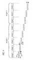
- FIG. 4is a plan view of formed wire useful for rolling about an axis into an aortic trunk segment and a first iliac branch segment support structure in accordance with the present invention.
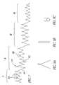
- FIG. 5is a schematic representation of another embodiment of the wire support structure for the bifurcated vascular prosthesis of the present invention, showing a main body support structure and separate branch support structures.
- FIG. 6is a schematic representation of the three-part wire support structure as in FIG. 5 , illustrating the sliding articulation between the branch supports and the main body support.
- FIG. 7is a plan view of formed wire useful for rolling about an axis to form a branch support structure in accordance with the three-part support embodiment of the present invention shown in FIG. 5 .
- FIGS. 8A , 8 B and 8 Care enlargements of the apexes delineated by lines A, B and C, respectively, in FIG. 7 .
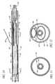
- FIG. 9is side elevational cross-section of a bifurcation graft delivery catheter in accordance with the present invention.
- FIG. 10is an enlargement of the portion delineated by the line 10 - 10 in FIG. 9 .
- FIG. 11is a cross-section taken along the line 11 - 11 in FIG. 10 .
- FIG. 12is a cross-section taken along the line 12 - 12 in FIG. 10 .
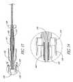
- FIG. 13is a fragmentary side elevational view of an enhanced flexibility embodiment of the present invention.
- FIG. 13Ais a fragmentary side elevational view of a further feature of the deployment catheter in accordance with the present invention.
- FIG. 14is a enlarged detail view taken along the line 14 - 14 in FIG. 13 .
- FIG. 15is a schematic representation of a bifurcated graft deployment catheter of the present invention, positioned within the ipsilateral iliac and the aorta, with the contralateral guidewire positioned within the contralateral iliac.
- FIG. 16is a schematic representation as in FIG. 15 , with the outer sheath proximally retracted and the compressed iliac branches of the graft moving into position within the iliac arteries.
- FIG. 17is a schematic representation as in FIG. 16 , with the compressed iliac branches of the graft within the iliac arteries, and the main aortic trunk of the graft deployed within the aorta.
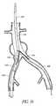
- FIG. 18is a schematic representation as in FIG. 17 , with the contralateral iliac branch of the graft deployed.
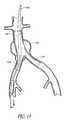
- FIG. 19is a schematic representation as in FIG. 18 , following deployment of the ipsilateral branch of the graft.
- FIG. 1there is disclosed a schematic representation of the abdominal part of the aorta and its principal branches.
- the abdominal aorta 30is characterized by a right renal artery 32 and left renal artery 34 .
- the large terminal branches of the aortaare the right and left common iliac arteries 36 and 38 .
- Additional vesselse.g., second lumbar, testicular, inferior mesenteric, middle sacral
- An expanded bifurcated endoluminal vascular prosthesis 102in accordance with one aspect of the present invention, is illustrated spanning aneurysms 103 , 104 and 105 .
- prosthesis configurationsare disclosed herein, these are only examples of prostheses which are deployable using the deployment catheter of the present invention.
- the deployment cathetermay be used to deploy essentially any self expandable bifurcated or straight segment prosthesis, as will be apparent to those of skill in the art in view of the disclosure herein.
- the endoluminal vascular prosthesis 102includes a polymeric sleeve 106 and a tubular wire support 107 , illustrated in situ in FIG. 1 .
- the sleeve 106 and wire support 107are more readily visualized in the exploded view shown in FIG. 3 .
- the endoluminal prosthesis 102 illustrated and described hereindepicts an embodiment in which the polymeric sleeve 106 is situated concentrically outside of the tubular wire support 107 .
- other embodimentsmay include a sleeve situated instead concentrically inside the wire support or on both of the inside and the outside of the wire support.
- the wire supportmay be embedded within a polymeric matrix or layer which makes up the sleeve. Regardless of whether the sleeve 106 is inside or outside the wire support 107 , the sleeve may be attached to the wire support by any of a variety of means, as has been previously discussed.
- the tubular wire support 107comprises a primary component 108 for traversing the aorta and a first iliac, and a branch component 109 for extending into the second iliac.
- the primary component 108may be formed from a continuous single length of wire, throughout both the aorta trunk portion and the iliac branch portion. See FIGS. 3 and 4 .
- each iliac branch componentcan be formed separately from the aorta trunk portion. Construction of the graft from a three part cage conveniently facilitates the use of different gauge wire in the different components (e.g. 0.014′′ diameter main trunk and 0.012′′ diameter branch components).
- the wire support 107is preferably formed in a plurality of discrete segments, connected together and oriented about a common axis.
- Section Acorresponds to the aorta trunk portion of the primary component 108 , and includes segments 1 - 5 .
- Segments 6 - 8correspond to the iliac branch portion of the primary component 108 .
- each of the components of the tubular wire support 107can be varied considerably in diameter, length, and expansion coefficient, depending upon the intended application.
- the aorta trunk portion (section A) of primary component 108will have a length within the range of from about 5 cm to about 12 cm, and, typically within the range of from about 9 cm to about 10 cm.
- the unconstrained outside expanded diameter of the section A portion of the primary component 108will typically be within the range of from about 20 mm to about 40 mm.
- the unconstrained expanded outside diameter of the section A portion of primary component 108can be constant or substantially constant throughout the length of section A, or can be tapered from a relatively larger diameter at the proximal end to a relatively smaller diameter at the bifurcation.
- the diameter of the distal end of section Awill be on the order of no more than about 95% and, preferably, no more than about 85% of the diameter of the proximal end of section A.
- Section C lengthwill generally be within the range of from about 1 cm to about 5 cm, and section C diameter will typically be within the range of from about 10 mm to about 20 mm.
- the wire cage 107is dividable into a proximal zone 110 , a central zone 111 and a distal zone 112 .
- the wire cage 107can have a transitional tapered and or stepped diameter within a given zone.
- Each segmenthas a repeating pattern of proximal bends 60 connected to corresponding distal bends 62 by wall sections 64 which extend in a generally zig-zag configuration when the segment is radially expanded.
- Each segmentis connected to the adjacent segment through a connector 66 , and one or more links 70 (see FIG. 6 ).
- the connector 66 in the illustrated embodimentcomprises two wall sections 64 which connect a proximal bend 60 on a first segment with a distal bend 62 on a second, adjacent segment.
- the connector 66may additionally be provided with a connector bend 68 , which may be used to impart increased radial strength to the graft and/or provide a tie site for a circumferentially extending suture.
- section Ais intended for deployment within the aorta whereas section B is intended to be deployed within a first iliac.
- section Bwill preferably have a smaller expanded diameter than section A. This may be accomplished by providing fewer proximal and distal bends 60 , 62 per segment in section B or in other manners as will be apparent to those of skill in the art in view of the disclosure herein.
- section Bhas one fewer proximal bend 60 per segment than does each segment in section A. This facilitates wrapping of the wire into a tubular prosthesis cage such as that illustrated in FIG. 3 , so that the iliac branch has a smaller diameter than the aorta branch.
- the second branchis preferably formed from a section of wire in accordance with the general principles discussed above, and in a manner that produces a similarly dimensioned wire cage as that produced by section B.
- the second iliac branch (section C)may be attached at the bifurcation to section A and/or section B in any of a variety of manners, to provide a secure junction therebetween.
- one or two of the proximal bends 60 on section Cwill be secured to the corresponding distal bends 62 on the distal most segment of section A.
- Attachmentmay be accomplished such as through the use of a circumferentially threaded suture, through links 70 as has been discussed previously, through soldering or other attachment means.
- the attachment meanswill be influenced by the desired flexibility of the graft at the bifurcation, which will in turn be influenced by the method of deployment of the vascular graft as will be apparent to those of skill in the art in view of the disclosure herein.
- the tubular wire supportcomprises a main body, or aortic trunk portion 200 and right 202 and left 204 iliac branch portions.
- Right and left designationscorrespond to the anatomic designations of right and left common iliac arteries.
- the proximal end 206 of the aortic trunk portion 200has apexes 211 - 216 adapted for connection with the complementary apexes on the distal ends 208 and 210 of the right 202 and left 204 iliac branch portions, respectively.
- the central or medial apex 213 in the foreground (anterior) of the aortic trunk portion 200is linked with 213 (R) on the right iliac portion 202 and 213 (L) on the left iliac portion 204 .
- the central apex 214 in the background (posterior)is linked with 214 (R) on the right iliac portion 202 and 214 (L) on the left iliac portion 204 .
- Each of these linkageshas two iliac apexes joined with one aortic branch apex.
- the medial most apexes 218 (R) and (L) of the iliac branch portions 202 and 204are linked together, without direct connection with the aortic truck portion 200 .
- the medial apexes 213 and 214function as pivot points about which the right and left iliac branches 202 , 204 can pivot to accommodate unique anatomies.
- the right and left iliac branches 202 , 204are illustrated at an angle of about 45° to each other, they are articulable through at least an angle of about 90° and preferably at least about 120°.
- the illustrated embodimentallows articulation through about 180° while maintaining patency of the central lumen.
- the apexes 213 and 214can be displaced proximally from the transverse plane which roughly contains apexes 211 , 212 , 215 and 216 by a minor adjustment to the fixture about which the wire is formed.
- Advancing the pivot point proximally relative to the lateral apexesopens the unbiased angle between the iliac branches 202 and 204 .
- the pivot pointis formed by a moveable link between an eye on apex 213 and two apexes 213 R and 213 L folded therethrough.
- the diameter of the eye at apex 213may be slightly larger than the diameter of the eye on other apexes throughout the graft.
- the diameter of the eye at apex 213 in one embodiment made from 0.014′′ diameter wireis about 0.059′′, compared to a diameter of about 0.020′′ for eyes elsewhere in the graft.
- pivot points 213 , 214in the illustrated embodiment are on the medial plane, they may be moved laterally such as, for example, to the axis of each of the iliac branches.
- each iliac branchwill have an anterior and a posterior pivot link on or about its longitudinal axis, for a total of four unique pivot links at the bifurcation.
- the pivot pointscan be moved as far as to lateral apexes 211 and 216 .
- Other variationswill be apparent to those of skill in the art in view of the disclosure herein.
- the remaining links between the aorta trunk portion 200 and the iliac branches 202 , 204preferably permit axial compression and expansion.
- at least one and preferably several links lateral to the pivot point in the illustrated embodimentpermit axial compression or shortening of the graft to accommodate lateral pivoting of the iliac branch.
- any links medial of the pivot pointpreferably permit axial elongation to accommodate lateral rotation of the branch. In this manner, the desired range of rotation of the iliac branches may be accomplished with minimal deformation of the wire, and with patency of the graft optimized throughout the angular range of motion.
- the lateral linkages, 211 and 212 for the right iliac, and 215 and 216 for the left iliacmay be different from the previously described apex-to-apex linkage configurations.
- the lateral linkagesare preferably slideable linkages, wherein a loop formed at the distal end of the iliac apex slidably engages a strut of the corresponding aortic truck portion.
- the loop and strut orientationmay be reversed, as will be apparent to those of skill in the art. Interlocking “elbows” without any distinct loop may also be used.
- Such an axially compressible linkage on the lateral margins of the assembled wire support structureallow the iliac branch portions much greater lateral flexibility, thereby facilitating placement in patients who often exhibit a variety of iliac branch asymmetries and different angles of divergence from the aortic trunk.
- FIG. 7there is illustrated a plan view of a single formed wire used for rolling about a longitudinal axis to produce a four segment straight tubular wire support for an iliac limb.
- the formed wireexhibits distinct segments, each corresponding to an individual tubular segment in the tubular supports 202 or 204 (See FIG. 5 ).
- the distal segment Iis adapted to articulate with the aortic trunk portion 200 and the adjacent iliac limb portion.
- the distal segment (I)has two apexes (e.g. corresponding to 211 and 212 on the right iliac portion 202 in FIG. 5 ) which form a loop adapted to slidably engage a strut in the lateral wall of the aortic portion.
- articulating loops (A)are enlarged in FIG. 8A .
- the loopsare preferably looped around a strut on the corresponding apex of the proximal aortic segment to provide a sliding linkage.
- the other apexes on the distal segment (I) of an iliac limbare designed to link with a loop on the corresponding apex of the proximal aortic segment. Because many variations of this linkage are consistent with the present invention the form of the corresponding apexes may vary.
- the apexes (B)form a narrow U-shape, having an inside diameter of about 0.019 inches in an embodiment made from 0.012 inch Conichrome wire (tensile strength 300 ksi minimum) as illustrated in FIG. 8B .
- the U-shaped, elongated axial portion of the apex shown in FIG. 8Bpermits the apex to be wrapped through and around a corresponding loop apex of the proximal aortic segment.
- the wire support illustrated in FIGS. 5 and 6comprises a main body support structure formed from one or more lengths of wire and having a proximal end, a distal end and a central lumen extending along a longitudinal axis.
- the wire supportalso comprises a first branch support structure formed from one or more lengths of wire and having a proximal end, a distal end and a central lumen therethrough.
- the first branch support structureis pivotably connected to the proximal end of the main body support structure.
- the tubular wire supportfurther comprises a second branch support structure formed from one or more lengths of wire and having a proximal end, a distal end and a central lumen extending therethrough.
- the distal end of the second branch support structureis pivotably connected to the proximal end of the main body support structure.
- first and second branch structuresmay be joined together by a flexible linkage, formed for example between apexes 218 (R) and 218 (L) in FIG. 5 .
- a flexible linkageformed for example between apexes 218 (R) and 218 (L) in FIG. 5 .
- the first and second branch support structurescan hinge laterally outward from the longitudinal axis without compromising the volume of the lumen.
- the branchesmay enjoy a wide range of lateral movement, thereby accommodating a variety of patient and vessel heterogeneity.
- Additional corresponding apexes between the main trunk and each iliac branchmay also be connected, or may be free floating within the outer polymeric sleeve.
- Axially compressible lateral linkagesdiscussed above and illustrated in FIG. 6 , may optionally be added.
- proximal apexes (C) of the iliac limb portionsare adapted to link with the distal apexes of the next segment.
- These proximal apexespreferably form loops, such as those illustrated in FIG. 8C , wherein the elongated axial portions of the corresponding proximal apex in the adjacent segment can wrap around the loop, thereby providing flexibility of the graft.
- the wiremay be made from any of a variety of different alloys and wire diameters or non-round cross-sections, as has been discussed.
- the wire gaugeremains substantially constant throughout section A of the primary component 49 and steps down to a second, smaller cross-section throughout section B of primary component 108 .
- a wire diameter of approximately 0.018 inchesmay be useful in the aorta trunk portion of a graft having five segments each having 2.0 cm length per segment, each segment having six struts intended for use in the aorta, while a smaller diameter such as 0.012 inches might be useful for segments of the graft having 6 struts per segment intended for the iliac artery.
- the wire diametermay be tapered throughout from the proximal to distal ends of the section A and/or section B portions of the primary component 108 .
- the wire diametermay be tapered incremental or stepped down, or stepped up, depending on the radial strength requirements of each particular clinical application.
- the wirehas a cross-section of about 0.018 inches in the proximal zone 110 and the wire tapers down regularly or in one or more steps to a diameter of about 0.012 inches in the distal zone 112 of the graft 102 . End point dimensions and rates of taper can be varied widely, within the spirit of the present invention, depending upon the desired clinical performance.
- the collapsed prosthesis in accordance with the present inventionhas a diameter in the range of about 2 mm to about 10 mm.
- the maximum diameter of the collapsed prosthesisis in the range of about 3 mm to 6 mm (12 to 18 French).
- Some embodiments of the delivery catheter including the prosthesiswill be in the range of from 18 to 20 or 21 French; other embodiments will be as low as 19 F, 16 F, 14 F, or smaller.
- the expanded endoluminal vascular prosthesishas radially self-expanded to a diameter anywhere in the range of about 20 to 40 mm, corresponding to expansion ratios of about 1:2 to 1:20.
- the expansion ratiosrange from about 1:4 to 1:8, more preferably from about 1:4 to 1:6.
- the self expandable bifurcation graft of the present inventioncan be deployed at a treatment site in accordance with any of a variety of techniques as will be apparent to those of skill in the art.
- One such techniqueis disclosed in copending patent application Ser. No. 08/802,478 entitled Bifurcated Vascular Graft and Method and Apparatus for Deploying Same, filed Feb. 20, 1997, the disclosure of which is incorporated in its entirety herein by reference.
- FIG. 9A partial cross-sectional side elevational view of one deployment apparatus 120 in accordance with the present invention is shown in FIG. 9 .
- the deployment apparatus 120comprises an elongate flexible multicomponent tubular body 122 having a proximal end 124 and a distal end 126 .
- the tubular body 122 and other components of this systemcan be manufactured in accordance with any of a variety of techniques well known in the catheter manufacturing field. Suitable materials and dimensions can be readily selected taking into account the natural anatomical dimensions in the iliacs and aorta, together with the dimensions of the desired percutaneous access site.
- the elongate flexible tubular body 122comprises an outer sheath 128 which is axially movably positioned upon an intermediate tube 130 .
- a central tubular core 132is axially movably positioned within the intermediate tube 130 .
- the outer tubular sheathcomprises extruded PTFE, having an outside diameter of about 0.250′′ and an inside diameter of about 0.230′′.
- the tubular sheath 128is provided at its proximal end with a manifold 134 , having a hemostatic valve 136 thereon and access ports such as for the infusion of drugs or contrast media as will be understood by those of skill in the art.
- the outer tubular sheath 128has an axial length within the range of from about 40′′ to about 55′′, and, in one embodiment of the deployment device 120 having an overall length of 110 cm, the axial length of the outer tubular sheath 128 is about 52 cm and the outside diameter is no more than about 0.250′′.
- the distal end 129 of the tubular sheath 128is located at least about 16 cm proximally of the distal end 126 of the deployment catheter 120 in stent loaded configuration.
- a distal segment of the deployment catheter 120comprises an outer tubular housing 138 , which terminates distally in an elongate flexible tapered distal tip 140 .
- the distal housing 138 and tip 140are axially immovably connected to the central core 132 at a connection 142 .
- the central tubular core 132is axially movably positioned within but rotationally locked to the intermediate tube 130 .
- the intermediate tube 130is preferably also axially movably positioned within but rotationally locked to the outer sheath 128 . In this manner, the rotational orientation of the central tubular core 132 remains fixed with respect to the rotational orientation of the outer sheath 128 .
- Rotational engagementcan be accomplished in any of a variety of ways, normally involving complementary surface structures such as keys or splines on the associated components.
- the central tubular core 132can be provided with a radially outwardly extending projection, along a portion or all of its axial length. This projection is slidably received within a radially outwardly extending slot on the interior surface of the intermediate tube 130 , or component secured thereto.
- a radially inwardly extending projection on intermediate tube 130 or associated componentcan be received with an axially extending recess on the outer surface of the central tubular core 132 .
- the cross section of the central tubular core 132deviates from circular by the provision of one or two opposing flat sides extending axially along its length.
- a corresponding apertureis provided in a rotational lock 125 provided at the proximal end of the intermediate tube 130 . See FIG. 9 .
- rotation of the intermediate tube 130will cause a similar rotation of the central tubular core 132 .
- the intermediate tube 130is provided with one or two opposing flat surfaces to be slidably received through a complementary aperture in a rotational lock 133 on manifold 134 . See FIG. 9 .
- the resulting assemblyenables rotation of the manifold 134 to cause a commensurate rotation of the intermediate tube 130 and central tubular core 132 .
- Specific dimensions and design details of the rotational lock disclosed hereinwill be readily apparent to those of skill in the art in view of the disclosure herein.
- a junction 131is formed between the distal end 129 of outer sheath 128 and outer tubular housing 138 . Proximal retraction of the outer sheath 128 with respect to the intermediate tube 130 and outer tubular housing 138 will expose the compressed iliac branches of the graft, as will be discussed in more detail below.
- the distal tip 140preferably tapers from an outside diameter of about 0.225′′ at its proximal end to an outside diameter of about 0.070′′ at the distal end thereof.
- the overall length of the distal tip 140 in one embodiment of the deployment catheter 120is about 3′′. However, the length and rate of taper of the distal tip 140 can be varied depending upon the desired trackability and flexibility characteristics.
- the distal end of the housing 138is secured to the proximal end of the distal tip 140 such as by thermal bonding, adhesive bonding, and/or any of a variety of other securing techniques known in the art.
- the proximal end of distal tip 140is preferably also directly or indirectly connected to the central core 132 such as by a friction fit and/or adhesive bonding.
- the central core 132preferably comprises a length of hypodermic needle tubing.
- the hypodermic needle tubingmay extend throughout the length of the catheter to the proximal end thereof, or may be secured to the distal end of a proximal extrusion as illustrated for example in FIG. 6 .
- a central guidewire lumen 144extends throughout the length of the tubular central core 132 , having a distal exit port 146 and a proximal access port 148 as will be understood by those of skill in the art.
- a bifurcated endoluminal graft 150is illustrated in a compressed configuration within the deployment catheter 120 .
- the graft 150comprises a distal aortic section 152 , a proximal ipsilateral iliac portion 154 , and a proximal contralateral iliac portion 156 .
- the aortic trunk portion 152 of the graft 150is contained within the tubular housing 138 . Distal axial advancement of the central tubular core 132 will cause the distal tip 140 and housing 138 to advance distally with respect to the graft 150 , thereby permitting the aortic trunk portion 152 of the graft 150 to expand to its larger, unconstrained diameter.
- the tubular extension 160extends axially throughout the length of the graft 150 .
- a step 159axially immovably connects the tubular extension 160 to the intermediate tube 130 .
- the step 159provides a proximal stop surface to prevent proximal travel of the graft 150 on the catheter 120 .
- the function of step 159can be accomplished through any of a variety of structures as will be apparent to those of skill in the art in view of the disclosure herein.
- the step 159may comprise an annular ring or spacer which receives the tubular extension 160 at a central aperture therethrough, and fits within the distal end of the intermediate tube 130 .
- the intermediate tube 130can be reduced in diameter through a generally conical section or shoulder to the diameter of tubular extension 160 .
- Proximal retraction of the outer sheath 128will release the iliac branches 154 and 156 of the graft 150 .
- the iliac branches 154 and 156will remain compressed, within a first (ipsilateral) tubular sheath 162 and a second (contralateral) tubular sheath 164 .
- the first tubular sheath 162is configured to restrain the ipsilateral branch of the graft 150 in the constrained configuration, for implantation at the treatment site.
- the first tubular sheath 162is adapted to be axially proximally removed from the iliac branch, thereby permitting the branch to expand to its implanted configuration.
- the first tubular sheath 162comprises a thin walled PTFE extrusion having an outside diameter of about 0.215′′ and an axial length of about 7.5 cm.
- a proximal end of the tubular sheath 162is necked down such as by heat shrinking to secure the first tubular sheath 162 to the tubular extension 160 .
- proximal withdrawal of the intermediate tube 130will in turn proximally advance the first tubular sheath 162 relative to the graft 150 , thereby deploying the self expandable iliac branch of the graft 150 .
- the second tubular sheath 164is secured to the contralateral guidewire 166 , which extends outside of the tubular body 122 at a point 168 , such as may be conveniently provided at the junction 131 between the outer tubular sheath 128 and the distal housing 138 .
- the second tubular sheath 164is adapted to restrain the contralateral branch of the graft 150 in the reduced profile.
- the second tubular sheath 164has an outside diameter of about 0.215′′ and an axial length of about 7.5 cm.
- the second tubular sheath 164can have a significantly smaller cross-section than the first tubular sheath 162 , due to the presence of the tubular core 132 and intermediate tube 130 within the first iliac branch 154 .
- the second tubular sheath 164is secured at its proximal end to a distal end of the contralateral guidewire 166 .
- Thismay be accomplished through any of a variety of securing techniques, such as heat shrinking, adhesives, mechanical interfit and the like.
- the guidewireis provided with a knot or other diameter enlarging structure to provide an interference fit with the proximal end of the second tubular sheath 156 , and the proximal end of the second tubular sheath 156 is heat shrunk and/or bonded in the area of the knot to provide a secure connection.
- the contralateral guidewire 166can comprise any of a variety of structures, including polymeric monofilament materials, braided or woven materials, metal ribbon or wire, or conventional guidewires as are well known in the art.
- the distal component 134 of the central tubular core 132comprises a flexible wall such as a braided polyimide tubing.
- the polyimide tubinghas an inside diameter of about 0.059′′ and an outside diameter of about 0.071′′.
- An internal braidis made from 0.0015′′ stainless steel 304 wire at a pic count of about 50 braids per inch, such as may be obtained from Phelps Dodge (GA) or H.V. Technologies (GA).
- the use of flexible tubingsuch as spiral cut layers or woven or braided tubing in place of conventional stainless steel or other metal hypotubing increases the lateral flexibility of the assembled device, which facilitates the placement and deployment steps.
- a reinforcement structure 161is preferably provided within the catheter, spanning the junction 131 .
- the reinforcement structure 161is carried by the tubular extension 160 of intermediate tube 130 .
- the reinforcement structure 161is in the form of a tubular element such as a stainless steel hypotube.
- the illustrated hypotubehas a length within the range of from about 40 mm to about 60 mm, a wall thickness within the range of from about 0.002′′ to about 0.005′′ and is secured immovably to the tubular extension 160 .
- Any of a variety of other reinforcement structures 161can also be used, such as spiral cut or woven or braided layers, polymeric tubing and the like, depending upon the desired performance characteristics. By positioning the reinforcement structure 161 at about the axial location of the junction 131 , the flexibility characteristics of the catheter can be optimized, while permitting a highly flexible hypotube 134 .
- the dimensions of the reinforcement tube 161can be varied, depending upon the desired performance characteristics of the catheter.
- the reinforcement tubeextends proximally at least as far as the proximal stop 159 which will be discussed.
- the reinforcement tube 161may also extend distally as far as the distal stop 158 .
- the reinforcement tube 161extends distally beyond the proximal stop 159 for a length of about 4.8 inches.
- the reinforcing sleevehas an inside diameter of about 0.072 inches and an outside diameter of about 0.076 inches. Other dimensions may be utilized, depending upon the desired balance between flexibility and kink resistance, as well as other performance characteristics. See, e.g., FIG. 13 .
- the braided polyimide hypotube 134or other braided or woven reinforced tubular element can be secured to the enlarged diameter proximal component 134 of tubular core 132 (see FIG. 14 ) in any of a variety of ways.
- a threaded insert 163is adhesively bonded to the polyimide hypotube component 134 of the tubular core 132 using a flexible epoxy such as 310 T manufactured by Epotech (MASS.) or other adhesives known in the art.
- FIG. 13AA further optional feature of the deployment system in accordance with the present invention is illustrated in FIG. 13A .
- the distal end of the intermediate tube 130is illustrated as extending out of the distal end 129 of the outer sheath 128 .
- a slit 167is illustrated in the outer sheath, to accommodate the contralateral guidewire 166 .
- the distal end of the intermediate tube 130is provided with a proximal stop 159 , for supporting the graft as has been discussed and for connecting the tubular extension 160 to the intermediate tube 130 .
- the tubular extension 160extends distally and supports the proximal end 165 of the ipsilateral tubular sheath 162 .
- the proximal end 165 of ipsilateral tubular sheath 162is tapered such as by necking down the outside diameter of the ipsilateral tubular sheath 162 for bonding to the tubular extension 160 .
- a plug 163 having a generally conical shapemay be provided to fill the proximal end 165 of the ipsilateral tubular sheath 162 , thereby presenting a surface 167 for facing the graft (not illustrated).
- the plug 163may be manufactured in any of a variety of ways, such as by injection molding or machining, or by introducing a curable or otherwise hardenable agent into the proximal end 165 and curing it in place to provide a surface 167 .
- FIG. 10Another optional feature of the deployment catheter is a spacer 171 .
- the outside diameter of the ipsilateral tubular sheath 162tapers down to approximately the inside diameter of the tubular extension 160 , which is considerably smaller than the outside diameter of the intermediate tube 130 .
- This low diameter space between the ipsilateral tubular sheath 162 and intermediate tube 130creates an opportunity for the distal end of the outer sheath 128 to become engaged (snagged) with the proximal end 165 of sheath 162 as the outer sheath 128 is advanced distally along the deployment device. This may occur, for example, after the outer sheath 128 has been proximally retracted to release the contralateral graft, and thereafter distally advanced to support the ipsilateral graft during deployment of the contralateral graft.
- a spacer 171is preferably positioned to fill the space between the stop 159 and the sheath 162 .
- the spacer 171may be a solid component, such as a molded or machined part, or a tubular element such as an extrusion.
- the spacer 171comprises a molded tubular element having a diameter of about 0.185′′, a total axial length of about 0.153′′, and a length of about 0.74′′ from 159 to the distal end of 171 .
- a slot or recess 169is provided for receiving the joint between the proximal end of the contralateral branch and the contralateral guidewire 166 .
- the spacer 171may be assembled as a separately manufactured component, or may be integrally formed with either the stop 159 , the intermediate tube 130 or the sheath 162 .
- the free end of the contralateral guidewire 166is percutaneously inserted into the arterial system, such as at a first puncture in a femoral artery.
- the contralateral guidewireis advanced through the corresponding iliac towards the aorta, and crossed over into the contralateral iliac in accordance with cross over techniques which are well known in the art.
- the contralateral guidewireis then advanced distally down the contralateral iliac where it exits the body at a second percutaneous puncture site.
- the deployment catheter 120is thereafter percutaneously inserted into the first puncture, and advanced along a guidewire (e.g. 0.035 inch) through the ipsilateral iliac and into the aorta.
- a guidewiree.g. 0.035 inch
- slack produced in the contralateral guidewire 166is taken up by proximally withdrawing the guidewire 166 from the second percutaneous access site.
- the deployment catheter 120is positioned in the manner generally illustrated in FIG. 13 .
- the outer sheath 128is proximally withdrawn while maintaining the axial position of the overall deployment catheter 120 , thereby releasing the first and second iliac branches of the graft 150 .
- Proximal advancement of the deployment catheter 120 and contralateral guidewire 166can then be accomplished, to position the iliac branches of the graft 150 within the iliac arteries as illustrated.
- the central core 132is distally advanced thereby distally advancing the distal-housing 138 as has been discussed. This exposes the aortic trunk of the graft 150 , which deploys into its fully expanded configuration within the aorta.
- the contralateral guidewire 166is thereafter proximally withdrawn, thereby by proximally withdrawing the second sheath 164 from the contralateral iliac branch 156 of the graft 150 . This may be preceded by the step of distally advancing the outer sheath 128 up to the bifurcation to provide support while the second sheath 164 is removed.
- the contralateral branch 156 of the graft 150thereafter self expands to fit within the iliac artery.
- the guidewire 166 and sheath 164may thereafter be proximally withdrawn and removed from the patient, by way of the second percutaneous access site.
- the deployment catheter 120may be proximally withdrawn to release the ipsilateral branch 154 of the graft 150 from the first tubular sheath 162 as shown in FIG. 17 .
- a central lumen through the aortic trunk 152 and ipsilateral branch 154is sufficiently large to permit proximal retraction of the deployment catheter 120 through the deployed bifurcated graft 150 .
- the deployment catheter 120may thereafter be proximally withdrawn from the patient by way of the first percutaneous access site.
Landscapes
- Health & Medical Sciences (AREA)
- Engineering & Computer Science (AREA)
- Biomedical Technology (AREA)
- Cardiology (AREA)
- Oral & Maxillofacial Surgery (AREA)
- Transplantation (AREA)
- Heart & Thoracic Surgery (AREA)
- Vascular Medicine (AREA)
- Life Sciences & Earth Sciences (AREA)
- Animal Behavior & Ethology (AREA)
- General Health & Medical Sciences (AREA)
- Public Health (AREA)
- Veterinary Medicine (AREA)
- Gastroenterology & Hepatology (AREA)
- Pulmonology (AREA)
- Prostheses (AREA)
Abstract
Description
Claims (8)
Priority Applications (1)
| Application Number | Priority Date | Filing Date | Title |
|---|---|---|---|
| US11/189,101US8147535B2 (en) | 1998-12-11 | 2005-07-25 | Bifurcation graft deployment catheter |
Applications Claiming Priority (6)
| Application Number | Priority Date | Filing Date | Title |
|---|---|---|---|
| US09/210,280US6187036B1 (en) | 1998-12-11 | 1998-12-11 | Endoluminal vascular prosthesis |
| US09/251,363US6197049B1 (en) | 1999-02-17 | 1999-02-17 | Articulating bifurcation graft |
| US09/525,778US6500202B1 (en) | 1998-12-11 | 2000-03-15 | Bifurcation graft deployment catheter |
| US09/747,094US6660030B2 (en) | 1998-12-11 | 2000-12-22 | Bifurcation graft deployment catheter |
| US10/675,060US6953475B2 (en) | 1998-12-11 | 2003-09-30 | Bifurcation graft deployment catheter |
| US11/189,101US8147535B2 (en) | 1998-12-11 | 2005-07-25 | Bifurcation graft deployment catheter |
Related Parent Applications (1)
| Application Number | Title | Priority Date | Filing Date |
|---|---|---|---|
| US10/675,060ContinuationUS6953475B2 (en) | 1998-12-11 | 2003-09-30 | Bifurcation graft deployment catheter |
Publications (2)
| Publication Number | Publication Date |
|---|---|
| US20060020320A1 US20060020320A1 (en) | 2006-01-26 |
| US8147535B2true US8147535B2 (en) | 2012-04-03 |
Family
ID=46257356
Family Applications (3)
| Application Number | Title | Priority Date | Filing Date |
|---|---|---|---|
| US09/747,094Expired - LifetimeUS6660030B2 (en) | 1998-12-11 | 2000-12-22 | Bifurcation graft deployment catheter |
| US10/675,060Expired - LifetimeUS6953475B2 (en) | 1998-12-11 | 2003-09-30 | Bifurcation graft deployment catheter |
| US11/189,101Expired - Fee RelatedUS8147535B2 (en) | 1998-12-11 | 2005-07-25 | Bifurcation graft deployment catheter |
Family Applications Before (2)
| Application Number | Title | Priority Date | Filing Date |
|---|---|---|---|
| US09/747,094Expired - LifetimeUS6660030B2 (en) | 1998-12-11 | 2000-12-22 | Bifurcation graft deployment catheter |
| US10/675,060Expired - LifetimeUS6953475B2 (en) | 1998-12-11 | 2003-09-30 | Bifurcation graft deployment catheter |
Country Status (1)
| Country | Link |
|---|---|
| US (3) | US6660030B2 (en) |
Cited By (2)
| Publication number | Priority date | Publication date | Assignee | Title |
|---|---|---|---|---|
| US20140277330A1 (en)* | 2013-03-13 | 2014-09-18 | Cook Medical Technologies Llc | Pre-Loaded Iliac Branch Device and Methods of Deployment |
| US10772717B2 (en) | 2009-05-01 | 2020-09-15 | Endologix, Inc. | Percutaneous method and device to treat dissections |
Families Citing this family (117)
| Publication number | Priority date | Publication date | Assignee | Title |
|---|---|---|---|---|
| US8728143B2 (en) | 1996-06-06 | 2014-05-20 | Biosensors International Group, Ltd. | Endoprosthesis deployment system for treating vascular bifurcations |
| US7686846B2 (en)* | 1996-06-06 | 2010-03-30 | Devax, Inc. | Bifurcation stent and method of positioning in a body lumen |
| US7238197B2 (en) | 2000-05-30 | 2007-07-03 | Devax, Inc. | Endoprosthesis deployment system for treating vascular bifurcations |
| US6951572B1 (en)* | 1997-02-20 | 2005-10-04 | Endologix, Inc. | Bifurcated vascular graft and method and apparatus for deploying same |
| US7018401B1 (en) | 1999-02-01 | 2006-03-28 | Board Of Regents, The University Of Texas System | Woven intravascular devices and methods for making the same and apparatus for delivery of the same |
| US6261316B1 (en) | 1999-03-11 | 2001-07-17 | Endologix, Inc. | Single puncture bifurcation graft deployment system |
| US8034100B2 (en) | 1999-03-11 | 2011-10-11 | Endologix, Inc. | Graft deployment system |
| US6602280B2 (en) | 2000-02-02 | 2003-08-05 | Trivascular, Inc. | Delivery system and method for expandable intracorporeal device |
| WO2002039888A2 (en)* | 2000-11-15 | 2002-05-23 | Endologix, Inc. | Implantable vascular graft |
| US6733521B2 (en) | 2001-04-11 | 2004-05-11 | Trivascular, Inc. | Delivery system and method for endovascular graft |
| AU2002320456A1 (en) | 2001-07-26 | 2003-02-17 | Alveolus Inc. | Removable stent and method of using the same |
| DE10148185B4 (en)* | 2001-09-28 | 2005-08-11 | Alveolus, Inc. | Instrument for implanting vascular prostheses |
| US20030074055A1 (en)* | 2001-10-17 | 2003-04-17 | Haverkost Patrick A. | Method and system for fixation of endoluminal devices |
| US20100016943A1 (en) | 2001-12-20 | 2010-01-21 | Trivascular2, Inc. | Method of delivering advanced endovascular graft |
| US6964681B2 (en)* | 2002-01-29 | 2005-11-15 | Medtronic Vascular, Inc. | Flared stent and method of use |
| US7329268B2 (en) | 2002-07-02 | 2008-02-12 | Warsaw Orthopedic, Inc. | Expandable percutaneous sheath |
| US20040093056A1 (en) | 2002-10-26 | 2004-05-13 | Johnson Lianw M. | Medical appliance delivery apparatus and method of use |
| US7959671B2 (en) | 2002-11-05 | 2011-06-14 | Merit Medical Systems, Inc. | Differential covering and coating methods |
| US7875068B2 (en) | 2002-11-05 | 2011-01-25 | Merit Medical Systems, Inc. | Removable biliary stent |
| US7527644B2 (en) | 2002-11-05 | 2009-05-05 | Alveolus Inc. | Stent with geometry determinated functionality and method of making the same |
| US7637942B2 (en) | 2002-11-05 | 2009-12-29 | Merit Medical Systems, Inc. | Coated stent with geometry determinated functionality and method of making the same |
| ES2325249T3 (en) | 2002-11-08 | 2009-08-31 | Jacques Seguin | ENDOVASCULAR PROTESIS FOR A FORK. |
| ITRM20020596A1 (en)* | 2002-11-27 | 2004-05-28 | Mauro Ferrari | IMPLANT VASCULAR PROSTHESIS WITH COMBINED, LAPAROSCOPIC AND ENDOVASCULAR TECHNIQUES, FOR THE TREATMENT OF ABDOMINAL AORTIC ANEURYSMS, AND OPERATIONAL EQUIPMENT FOR THE RELEASE OF A PROSTHESIS EQUIPPED WITH ANCHORING STENTS. |
| US7367989B2 (en) | 2003-02-27 | 2008-05-06 | Scimed Life Systems, Inc. | Rotating balloon expandable sheath bifurcation delivery |
| US7314480B2 (en) | 2003-02-27 | 2008-01-01 | Boston Scientific Scimed, Inc. | Rotating balloon expandable sheath bifurcation delivery |
| US7637934B2 (en) | 2003-03-31 | 2009-12-29 | Merit Medical Systems, Inc. | Medical appliance optical delivery and deployment apparatus and method |
| US7604660B2 (en) | 2003-05-01 | 2009-10-20 | Merit Medical Systems, Inc. | Bifurcated medical appliance delivery apparatus and method |
| US20050033416A1 (en)* | 2003-05-02 | 2005-02-10 | Jacques Seguin | Vascular graft and deployment system |
| US11596537B2 (en) | 2003-09-03 | 2023-03-07 | Bolton Medical, Inc. | Delivery system and method for self-centering a proximal end of a stent graft |
| US20080264102A1 (en) | 2004-02-23 | 2008-10-30 | Bolton Medical, Inc. | Sheath Capture Device for Stent Graft Delivery System and Method for Operating Same |
| US20070198078A1 (en)* | 2003-09-03 | 2007-08-23 | Bolton Medical, Inc. | Delivery system and method for self-centering a Proximal end of a stent graft |
| US8500792B2 (en) | 2003-09-03 | 2013-08-06 | Bolton Medical, Inc. | Dual capture device for stent graft delivery system and method for capturing a stent graft |
| US9198786B2 (en) | 2003-09-03 | 2015-12-01 | Bolton Medical, Inc. | Lumen repair device with capture structure |
| US8292943B2 (en) | 2003-09-03 | 2012-10-23 | Bolton Medical, Inc. | Stent graft with longitudinal support member |
| US7763063B2 (en) | 2003-09-03 | 2010-07-27 | Bolton Medical, Inc. | Self-aligning stent graft delivery system, kit, and method |
| US11259945B2 (en) | 2003-09-03 | 2022-03-01 | Bolton Medical, Inc. | Dual capture device for stent graft delivery system and method for capturing a stent graft |
| US7425219B2 (en)* | 2003-10-10 | 2008-09-16 | Arshad Quadri | System and method for endoluminal grafting of bifurcated and branched vessels |
| EP1691719B1 (en)* | 2003-10-14 | 2016-09-14 | Cook Medical Technologies LLC | Introducer for an iliac side branch device |
| US7998186B2 (en) | 2003-10-14 | 2011-08-16 | William A. Cook Australia Pty. Ltd. | Introducer for a side branch device |
| US7887574B2 (en)* | 2003-12-23 | 2011-02-15 | Scimed Life Systems, Inc. | Stent delivery catheter |
| US7686841B2 (en) | 2003-12-29 | 2010-03-30 | Boston Scientific Scimed, Inc. | Rotating balloon expandable sheath bifurcation delivery system |
| US7922753B2 (en) | 2004-01-13 | 2011-04-12 | Boston Scientific Scimed, Inc. | Bifurcated stent delivery system |
| US8012192B2 (en) | 2004-02-18 | 2011-09-06 | Boston Scientific Scimed, Inc. | Multi-stent delivery system |
| US7225518B2 (en) | 2004-02-23 | 2007-06-05 | Boston Scientific Scimed, Inc. | Apparatus for crimping a stent assembly |
| US8377110B2 (en)* | 2004-04-08 | 2013-02-19 | Endologix, Inc. | Endolumenal vascular prosthesis with neointima inhibiting polymeric sleeve |
| US8109983B2 (en)* | 2004-08-06 | 2012-02-07 | Boston Scientific Scimed, Inc. | Medical device delivery systems |
| US7691137B2 (en) | 2004-09-28 | 2010-04-06 | Boston Scientific Scimed, Inc. | Rotatable sheath, assembly and method of manufacture of same |
| US20060089704A1 (en)* | 2004-10-25 | 2006-04-27 | Myles Douglas | Vascular graft and deployment system |
| US7699883B2 (en)* | 2004-10-25 | 2010-04-20 | Myles Douglas | Vascular graft and deployment system |
| EP1807022A2 (en)* | 2004-11-03 | 2007-07-18 | Jacques Seguin | Vascular graft and deployment system |
| US7713240B2 (en)* | 2005-09-13 | 2010-05-11 | Medtronic Minimed, Inc. | Modular external infusion device |
| US20070168013A1 (en)* | 2006-01-19 | 2007-07-19 | Myles Douglas | Vascular graft and deployment system |
| US20080071343A1 (en)* | 2006-09-15 | 2008-03-20 | Kevin John Mayberry | Multi-segmented graft deployment system |
| KR101659197B1 (en) | 2006-10-22 | 2016-09-22 | 이데브 테크놀로지스, 아이엔씨. | Devices and methods for stent advancement |
| MX2009004291A (en) | 2006-10-22 | 2009-09-07 | Idev Technologies Inc | Methods for securing strand ends and the resulting devices. |
| US8523931B2 (en) | 2007-01-12 | 2013-09-03 | Endologix, Inc. | Dual concentric guidewire and methods of bifurcated graft deployment |
| US20080288045A1 (en)* | 2007-02-22 | 2008-11-20 | Mohsin Saeed | Apparatus and method for implantation of a bifurcated endovascular prosthesis |
| US8821567B2 (en) | 2007-02-22 | 2014-09-02 | Mohsin Saeed | Apparatus and method for implantation of a bifurcated endovascular prosthesis |
| US9387308B2 (en) | 2007-04-23 | 2016-07-12 | Cardioguidance Biomedical, Llc | Guidewire with adjustable stiffness |
| JP2010524631A (en)* | 2007-04-23 | 2010-07-22 | インターヴェンショナル アンド サージカル イノヴェイションズ リミテッド ライアビリティ カンパニー | Guidewire with adjustable stiffness |
| WO2008136999A1 (en)* | 2007-04-30 | 2008-11-13 | The Board Of Trustees Of The Leland Stanford Junior University | Prevention of displacement of prosthetic devices within aneurysms |
| US8048147B2 (en) | 2007-06-27 | 2011-11-01 | Aga Medical Corporation | Branched stent/graft and method of fabrication |
| US8226701B2 (en) | 2007-09-26 | 2012-07-24 | Trivascular, Inc. | Stent and delivery system for deployment thereof |
| US8066755B2 (en) | 2007-09-26 | 2011-11-29 | Trivascular, Inc. | System and method of pivoted stent deployment |
| US8663309B2 (en) | 2007-09-26 | 2014-03-04 | Trivascular, Inc. | Asymmetric stent apparatus and method |
| US10159557B2 (en) | 2007-10-04 | 2018-12-25 | Trivascular, Inc. | Modular vascular graft for low profile percutaneous delivery |
| US20090105806A1 (en)* | 2007-10-23 | 2009-04-23 | Endologix, Inc | Stent |
| US8328861B2 (en) | 2007-11-16 | 2012-12-11 | Trivascular, Inc. | Delivery system and method for bifurcated graft |
| US8083789B2 (en) | 2007-11-16 | 2011-12-27 | Trivascular, Inc. | Securement assembly and method for expandable endovascular device |
| US10646363B2 (en)* | 2007-12-27 | 2020-05-12 | Cook Medical Technologies Llc | Endovascular device delivery system |
| WO2009105699A1 (en) | 2008-02-22 | 2009-08-27 | Endologix, Inc. | Design and method of placement of a graft or graft system |
| US8236040B2 (en)* | 2008-04-11 | 2012-08-07 | Endologix, Inc. | Bifurcated graft deployment systems and methods |
| US8333003B2 (en) | 2008-05-19 | 2012-12-18 | Boston Scientific Scimed, Inc. | Bifurcation stent crimping systems and methods |
| CN102076281B (en) | 2008-06-30 | 2014-11-05 | 波顿医疗公司 | Systems and methods for abdominal aortic aneurysm |
| EP2520320B1 (en) | 2008-07-01 | 2016-11-02 | Endologix, Inc. | Catheter system |
| US8454680B2 (en)* | 2008-07-10 | 2013-06-04 | Atrial Systems, Llc | Endovascular conduit device with low profile occlusion members |
| WO2010006243A2 (en)* | 2008-07-10 | 2010-01-14 | Atrial Systems, Llc | Endovascular conduit device for increasing safety of cardiac lead extraction and other vascular procedures |
| US20100049307A1 (en)* | 2008-08-25 | 2010-02-25 | Aga Medical Corporation | Stent graft having extended landing area and method for using the same |
| US8133199B2 (en) | 2008-08-27 | 2012-03-13 | Boston Scientific Scimed, Inc. | Electroactive polymer activation system for a medical device |
| US8641753B2 (en) | 2009-01-31 | 2014-02-04 | Cook Medical Technologies Llc | Preform for and an endoluminal prosthesis |
| EP3284447B1 (en) | 2009-03-13 | 2020-05-20 | Bolton Medical Inc. | System for deploying an endoluminal prosthesis at a surgical site |
| US20110054587A1 (en)* | 2009-04-28 | 2011-03-03 | Endologix, Inc. | Apparatus and method of placement of a graft or graft system |
| JP2012525239A (en) | 2009-05-01 | 2012-10-22 | エンドロジックス、インク | Transcutaneous methods and devices for treating dissociation (priority information and incorporation by reference) |
| WO2011008989A2 (en) | 2009-07-15 | 2011-01-20 | Endologix, Inc. | Stent graft |
| WO2011017123A2 (en) | 2009-07-27 | 2011-02-10 | Endologix, Inc. | Stent graft |
| EP3034036B1 (en) | 2009-10-13 | 2019-09-11 | Cook Medical Technologies LLC | Paraplegia prevention stent graft |
| US9095456B2 (en) | 2009-10-13 | 2015-08-04 | Cook Medical Technologies Llc | Paraplegia prevention stent graft |
| EP2506799A4 (en) | 2009-12-01 | 2014-10-29 | Altura Medical Inc | Modular endograft devices and associated systems and methods |
| WO2011081814A1 (en) | 2009-12-28 | 2011-07-07 | Cook Medical Technologies Llc | Endoluminal device with kink-resistant regions |
| US20110218617A1 (en)* | 2010-03-02 | 2011-09-08 | Endologix, Inc. | Endoluminal vascular prosthesis |
| US8663305B2 (en) | 2010-04-20 | 2014-03-04 | Medtronic Vascular, Inc. | Retraction mechanism and method for graft cover retraction |
| US8623064B2 (en)* | 2010-04-30 | 2014-01-07 | Medtronic Vascular, Inc. | Stent graft delivery system and method of use |
| US8747448B2 (en) | 2010-04-30 | 2014-06-10 | Medtronic Vascular, Inc. | Stent graft delivery system |
| US9023095B2 (en) | 2010-05-27 | 2015-05-05 | Idev Technologies, Inc. | Stent delivery system with pusher assembly |
| WO2012040240A1 (en) | 2010-09-20 | 2012-03-29 | Altura Medical, Inc. | Stent graft delivery systems and associated methods |
| US20120109279A1 (en) | 2010-11-02 | 2012-05-03 | Endologix, Inc. | Apparatus and method of placement of a graft or graft system |
| US9393100B2 (en) | 2010-11-17 | 2016-07-19 | Endologix, Inc. | Devices and methods to treat vascular dissections |
| US9155612B2 (en) | 2011-01-10 | 2015-10-13 | Intermountain Invention Management, Llc | Composite stent grafts for in situ assembly and related methods |
| US9486348B2 (en)* | 2011-02-01 | 2016-11-08 | S. Jude Medical, Cardiology Division, Inc. | Vascular delivery system and method |
| US8808350B2 (en) | 2011-03-01 | 2014-08-19 | Endologix, Inc. | Catheter system and methods of using same |
| EP3583916B1 (en)* | 2011-04-28 | 2023-12-06 | Cook Medical Technologies LLC | Apparatus for facilitating deployment of an endoluminal prosthesis |
| AU2012203620B9 (en) | 2011-06-24 | 2014-10-02 | Cook Medical Technologies Llc | Helical Stent |
| WO2013059623A1 (en) | 2011-10-21 | 2013-04-25 | Merit Medical Systems, Inc. | Devices and methods for stenting an airway |
| US8728148B2 (en) | 2011-11-09 | 2014-05-20 | Cook Medical Technologies Llc | Diameter reducing tie arrangement for endoluminal prosthesis |
| US8992595B2 (en) | 2012-04-04 | 2015-03-31 | Trivascular, Inc. | Durable stent graft with tapered struts and stable delivery methods and devices |
| US9498363B2 (en) | 2012-04-06 | 2016-11-22 | Trivascular, Inc. | Delivery catheter for endovascular device |
| EP2846743B1 (en) | 2012-04-12 | 2016-12-14 | Bolton Medical Inc. | Vascular prosthetic delivery device |
| US9066828B2 (en)* | 2012-06-15 | 2015-06-30 | Trivascular, Inc. | Endovascular delivery system with flexible and torqueable hypotube |
| CA2881535A1 (en) | 2012-08-10 | 2014-02-13 | Altura Medical, Inc. | Stent delivery systems and associated methods |
| US9308107B2 (en) | 2012-08-27 | 2016-04-12 | Cook Medical Technologies Llc | Endoluminal prosthesis and delivery device |
| WO2014144809A1 (en) | 2013-03-15 | 2014-09-18 | Altura Medical, Inc. | Endograft device delivery systems and associated methods |
| US9439751B2 (en) | 2013-03-15 | 2016-09-13 | Bolton Medical, Inc. | Hemostasis valve and delivery systems |
| WO2017004265A1 (en) | 2015-06-30 | 2017-01-05 | Endologix, Inc. | Locking assembly for coupling guidewire to delivery system |
| WO2017015498A1 (en) | 2015-07-22 | 2017-01-26 | Nitinol Devices And Components, Inc. | Graft dimpling to improve crimp profile and reduce delivery forces |
| JP7083249B2 (en) | 2015-07-30 | 2022-06-10 | トリバスキュラー・インコーポレイテッド | Intraluminal prosthesis deployment device and method |
| WO2021131857A1 (en)* | 2019-12-25 | 2021-07-01 | 川澄化学工業株式会社 | Stent |
| EP4585192A3 (en) | 2020-06-24 | 2025-10-15 | Bolton Medical, Inc. | Anti-backspin component for vascular prosthesis delivery device |
Citations (242)
| Publication number | Priority date | Publication date | Assignee | Title |
|---|---|---|---|---|
| US519928A (en) | 1894-05-15 | Wire fence | ||
| US1065935A (en) | 1911-03-09 | 1913-07-01 | Simmons Mfg Co | Wire bed-bottom fabric. |
| US2127903A (en) | 1936-05-05 | 1938-08-23 | Davis & Geck Inc | Tube for surgical purposes and method of preparing and using the same |
| US2437542A (en) | 1944-05-05 | 1948-03-09 | American Catheter Corp | Catheter-type instrument |
| US2845959A (en) | 1956-03-26 | 1958-08-05 | John B Sidebotham | Bifurcated textile tubes and method of weaving the same |
| US2990605A (en) | 1957-01-30 | 1961-07-04 | Demsyk Paul | Method of forming artificial vascular members |
| US3029819A (en) | 1959-07-30 | 1962-04-17 | J L Mcatee | Artery graft and method of producing artery grafts |
| US3096560A (en) | 1958-11-21 | 1963-07-09 | William J Liebig | Process for synthetic vascular implants |
| US3805301A (en) | 1972-07-28 | 1974-04-23 | Meadox Medicals Inc | Tubular grafts having indicia thereon |
| US4497074A (en) | 1976-04-05 | 1985-02-05 | Agence National De Valorisation De La Recherche (Anvar) | Organ prostheses |
| US4501263A (en) | 1982-03-31 | 1985-02-26 | Harbuck Stanley C | Method for reducing hypertension of a liver |
| US4503568A (en) | 1981-11-25 | 1985-03-12 | New England Deaconess Hospital | Small diameter vascular bypass and method |
| US4592754A (en) | 1983-09-09 | 1986-06-03 | Gupte Pradeep M | Surgical prosthetic vessel graft and catheter combination and method |
| US4617932A (en) | 1984-04-25 | 1986-10-21 | Elliot Kornberg | Device and method for performing an intraluminal abdominal aortic aneurysm repair |
| US4816028A (en) | 1987-07-01 | 1989-03-28 | Indu Kapadia | Woven vascular graft |
| US4840940A (en) | 1987-10-21 | 1989-06-20 | Sottiurai Vikrom S | Method for reducing the occurrence of distal anastomotic intimal hyperplasia using fractionated heparin |
| US4856516A (en) | 1989-01-09 | 1989-08-15 | Cordis Corporation | Endovascular stent apparatus and method |
| US4878906A (en) | 1986-03-25 | 1989-11-07 | Servetus Partnership | Endoprosthesis for repairing a damaged vessel |
| US4907336A (en) | 1987-03-13 | 1990-03-13 | Cook Incorporated | Method of making an endovascular stent and delivery system |
| US4922905A (en) | 1985-11-30 | 1990-05-08 | Strecker Ernst P | Dilatation catheter |
| US4981478A (en) | 1988-09-06 | 1991-01-01 | Advanced Cardiovascular Systems | Composite vascular catheter |
| US4994071A (en) | 1989-05-22 | 1991-02-19 | Cordis Corporation | Bifurcating stent apparatus and method |
| US5019090A (en) | 1988-09-01 | 1991-05-28 | Corvita Corporation | Radially expandable endoprosthesis and the like |
| EP0177330B1 (en) | 1984-10-01 | 1991-06-19 | Cook Incorporated | Percutaneous endovascular stent |
| US5064435A (en) | 1990-06-28 | 1991-11-12 | Schneider (Usa) Inc. | Self-expanding prosthesis having stable axial length |
| US5078726A (en) | 1989-02-01 | 1992-01-07 | Kreamer Jeffry W | Graft stent and method of repairing blood vessels |
| US5104399A (en) | 1986-12-10 | 1992-04-14 | Endovascular Technologies, Inc. | Artificial graft and implantation method |
| US5108424A (en) | 1984-01-30 | 1992-04-28 | Meadox Medicals, Inc. | Collagen-impregnated dacron graft |
| US5123917A (en) | 1990-04-27 | 1992-06-23 | Lee Peter Y | Expandable intraluminal vascular graft |
| US5133732A (en) | 1987-10-19 | 1992-07-28 | Medtronic, Inc. | Intravascular stent |
| US5135536A (en) | 1991-02-05 | 1992-08-04 | Cordis Corporation | Endovascular stent and method |
| US5156619A (en) | 1990-06-15 | 1992-10-20 | Ehrenfeld William K | Flanged end-to-side vascular graft |
| US5178634A (en) | 1989-03-31 | 1993-01-12 | Wilson Ramos Martinez | Aortic valved tubes for human implants |
| US5197976A (en) | 1991-09-16 | 1993-03-30 | Atrium Medical Corporation | Manually separable multi-lumen vascular graft |
| US5201757A (en) | 1992-04-03 | 1993-04-13 | Schneider (Usa) Inc. | Medial region deployment of radially self-expanding stents |
| US5256141A (en) | 1992-12-22 | 1993-10-26 | Nelson Gencheff | Biological material deployment method and apparatus |
| US5275622A (en) | 1983-12-09 | 1994-01-04 | Harrison Medical Technologies, Inc. | Endovascular grafting apparatus, system and method and devices for use therewith |
| US5282860A (en) | 1991-10-16 | 1994-02-01 | Olympus Optical Co., Ltd. | Stent tube for medical use |
| US5282824A (en) | 1990-10-09 | 1994-02-01 | Cook, Incorporated | Percutaneous stent assembly |
| US5304200A (en) | 1991-05-29 | 1994-04-19 | Cordis Corporation | Welded radially expandable endoprosthesis and the like |
| EP0596145A1 (en) | 1992-10-31 | 1994-05-11 | Schneider (Europe) Ag | Disposition for implanting a self-expanding endoprothesis |
| US5314472A (en) | 1991-10-01 | 1994-05-24 | Cook Incorporated | Vascular stent |
| US5314444A (en) | 1987-03-13 | 1994-05-24 | Cook Incorporated | Endovascular stent and delivery system |
| US5316023A (en) | 1992-01-08 | 1994-05-31 | Expandable Grafts Partnership | Method for bilateral intra-aortic bypass |
| US5320602A (en) | 1993-05-14 | 1994-06-14 | Wilson-Cook Medical, Inc. | Peel-away endoscopic retrograde cholangio pancreatography catheter and a method for using the same |
| US5330500A (en) | 1990-10-18 | 1994-07-19 | Song Ho Y | Self-expanding endovascular stent with silicone coating |
| US5342387A (en) | 1992-06-18 | 1994-08-30 | American Biomed, Inc. | Artificial support for a blood vessel |
| US5354308A (en) | 1992-05-01 | 1994-10-11 | Beth Israel Hospital Association | Metal wire stent |
| US5360443A (en) | 1990-06-11 | 1994-11-01 | Barone Hector D | Aortic graft for repairing an abdominal aortic aneurysm |
| US5366504A (en) | 1992-05-20 | 1994-11-22 | Boston Scientific Corporation | Tubular medical prosthesis |
| US5370683A (en) | 1992-03-25 | 1994-12-06 | Cook Incorporated | Vascular stent |
| US5387235A (en) | 1991-10-25 | 1995-02-07 | Cook Incorporated | Expandable transluminal graft prosthesis for repair of aneurysm |
| US5397355A (en) | 1994-07-19 | 1995-03-14 | Stentco, Inc. | Intraluminal stent |
| US5405377A (en) | 1992-02-21 | 1995-04-11 | Endotech Ltd. | Intraluminal stent |
| US5415664A (en) | 1994-03-30 | 1995-05-16 | Corvita Corporation | Method and apparatus for introducing a stent or a stent-graft |
| US5423886A (en) | 1987-05-11 | 1995-06-13 | Sorin Biomedica S.P.A. | Cyclically deformable haemocompatible and biocompatible devices coated with biocompatible carbonaceous material |
| US5425765A (en) | 1993-06-25 | 1995-06-20 | Tiefenbrun; Jonathan | Surgical bypass method |
| EP0659389A1 (en) | 1993-10-20 | 1995-06-28 | Schneider (Europe) Ag | Endoprothese |
| US5443500A (en) | 1989-01-26 | 1995-08-22 | Advanced Cardiovascular Systems, Inc. | Intravascular stent |
| US5443477A (en) | 1994-02-10 | 1995-08-22 | Stentco, Inc. | Apparatus and method for deployment of radially expandable stents by a mechanical linkage |
| US5443498A (en) | 1991-10-01 | 1995-08-22 | Cook Incorporated | Vascular stent and method of making and implanting a vacsular stent |
| US5456713A (en) | 1991-10-25 | 1995-10-10 | Cook Incorporated | Expandable transluminal graft prosthesis for repairs of aneurysm and method for implanting |
| US5458615A (en) | 1993-07-06 | 1995-10-17 | Advanced Cardiovascular Systems, Inc. | Stent delivery system |
| US5462530A (en) | 1992-04-09 | 1995-10-31 | Jang; G. David | Intravascular catheter with bailout feature |
| US5464450A (en) | 1991-10-04 | 1995-11-07 | Scimed Lifesystems Inc. | Biodegradable drug delivery vascular stent |
| US5489295A (en) | 1991-04-11 | 1996-02-06 | Endovascular Technologies, Inc. | Endovascular graft having bifurcation and apparatus and method for deploying the same |
| US5496365A (en) | 1992-07-02 | 1996-03-05 | Sgro; Jean-Claude | Autoexpandable vascular endoprosthesis |
| US5507771A (en) | 1992-06-15 | 1996-04-16 | Cook Incorporated | Stent assembly |
| US5507769A (en) | 1994-10-18 | 1996-04-16 | Stentco, Inc. | Method and apparatus for forming an endoluminal bifurcated graft |
| US5507767A (en) | 1992-01-15 | 1996-04-16 | Cook Incorporated | Spiral stent |
| US5522883A (en) | 1995-02-17 | 1996-06-04 | Meadox Medicals, Inc. | Endoprosthesis stent/graft deployment system |
| US5522881A (en) | 1994-06-28 | 1996-06-04 | Meadox Medicals, Inc. | Implantable tubular prosthesis having integral cuffs |
| US5545211A (en) | 1993-09-27 | 1996-08-13 | Sooho Medi-Tech Co., Ltd. | Stent for expanding a lumen |
| US5554118A (en) | 1991-05-24 | 1996-09-10 | Jang; G. David | Universal mode vascular catheter system |
| US5554181A (en) | 1994-05-04 | 1996-09-10 | Regents Of The University Of Minnesota | Stent |
| US5562726A (en) | 1991-10-25 | 1996-10-08 | Cook Incorporated | Expandable transluminal graft prosthesis for repair of aneurysm and method for implanting |
| US5562728A (en) | 1983-12-09 | 1996-10-08 | Endovascular Tech Inc | Endovascular grafting apparatus, system and method and devices for use therewith |
| US5571173A (en) | 1990-06-11 | 1996-11-05 | Parodi; Juan C. | Graft to repair a body passageway |
| EP0740928A2 (en) | 1995-04-12 | 1996-11-06 | Corvita Europe | Self-expanding stent for introducing a medical device in a body cavity and manufacturing process |
| US5575818A (en) | 1995-02-14 | 1996-11-19 | Corvita Corporation | Endovascular stent with locking ring |
| US5575816A (en) | 1994-08-12 | 1996-11-19 | Meadox Medicals, Inc. | High strength and high density intraluminal wire stent |
| EP0747020A2 (en) | 1995-06-07 | 1996-12-11 | Cook Incorporated | Improved barb and expandable transluminal graft prothesis for repair of aneurysm |
| US5591230A (en) | 1994-09-07 | 1997-01-07 | Global Therapeutics, Inc. | Radially expandable stent |
| US5591198A (en) | 1995-04-27 | 1997-01-07 | Medtronic, Inc. | Multiple sinusoidal wave configuration stent |
| US5591197A (en) | 1995-03-14 | 1997-01-07 | Advanced Cardiovascular Systems, Inc. | Expandable stent forming projecting barbs and method for deploying |
| US5593417A (en) | 1995-11-27 | 1997-01-14 | Rhodes; Valentine J. | Intravascular stent with secure mounting means |
| US5609627A (en) | 1994-02-09 | 1997-03-11 | Boston Scientific Technology, Inc. | Method for delivering a bifurcated endoluminal prosthesis |
| US5609628A (en) | 1995-04-20 | 1997-03-11 | Keranen; Victor J. | Intravascular graft and catheter |
| US5628786A (en) | 1995-05-12 | 1997-05-13 | Impra, Inc. | Radially expandable vascular graft with resistance to longitudinal compression and method of making same |
| US5628788A (en) | 1995-11-07 | 1997-05-13 | Corvita Corporation | Self-expanding endoluminal stent-graft |
| US5628783A (en) | 1991-04-11 | 1997-05-13 | Endovascular Technologies, Inc. | Bifurcated multicapsule intraluminal grafting system and method |
| US5630829A (en) | 1994-12-09 | 1997-05-20 | Intervascular, Inc. | High hoop strength intraluminal stent |
| US5632772A (en) | 1993-10-21 | 1997-05-27 | Corvita Corporation | Expandable supportive branched endoluminal grafts |
| EP0775470A1 (en) | 1995-11-14 | 1997-05-28 | Schneider (Europe) Ag | Stent delivery device and method for manufacturing a stent delivery device |
| US5639278A (en) | 1993-10-21 | 1997-06-17 | Corvita Corporation | Expandable supportive bifurcated endoluminal grafts |
| US5641373A (en) | 1995-04-17 | 1997-06-24 | Baxter International Inc. | Method of manufacturing a radially-enlargeable PTFE tape-reinforced vascular graft |
| US5643339A (en) | 1992-08-06 | 1997-07-01 | William Cook Europe A/S | Prosthetic device for sustaining a blood-vessel or hollow organ lumen |
| US5643312A (en) | 1994-02-25 | 1997-07-01 | Fischell Robert | Stent having a multiplicity of closed circular structures |
| US5643278A (en) | 1995-04-06 | 1997-07-01 | Leocor, Inc. | Stent delivery system |
| US5643171A (en) | 1993-05-04 | 1997-07-01 | Neocardia, Llc | Method and apparatus for uniform radiation treatment of vascular lumens |
| US5647952A (en) | 1996-04-01 | 1997-07-15 | Industrial Technology Research Institute | Chemical/mechanical polish (CMP) endpoint method |
| US5647857A (en) | 1995-03-16 | 1997-07-15 | Endotex Interventional Systems, Inc. | Protective intraluminal sheath |
| US5651174A (en) | 1992-03-19 | 1997-07-29 | Medtronic, Inc. | Intravascular radially expandable stent |
| US5653743A (en) | 1994-09-09 | 1997-08-05 | Martin; Eric C. | Hypogastric artery bifurcation graft and method of implantation |
| US5653746A (en) | 1994-03-08 | 1997-08-05 | Meadox Medicals, Inc. | Radially expandable tubular prosthesis |
| US5653747A (en) | 1992-12-21 | 1997-08-05 | Corvita Corporation | Luminal graft endoprostheses and manufacture thereof |
| US5662701A (en) | 1989-08-18 | 1997-09-02 | Endovascular Instruments, Inc. | Anti-stenotic method and product for occluded and partially occluded arteries |
| US5662614A (en) | 1995-05-09 | 1997-09-02 | Edoga; John K. | Balloon expandable universal access sheath |
| US5662580A (en) | 1994-12-08 | 1997-09-02 | Neocardia, Llc | Combined angioplasty and intravascular radiotherapy method and apparatus |
| US5662703A (en) | 1995-04-14 | 1997-09-02 | Schneider (Usa) Inc. | Rolling membrane stent delivery device |
| US5665115A (en) | 1992-02-21 | 1997-09-09 | Boston Scientific Technology, Inc. | Intraluminal stent |
| US5665117A (en) | 1995-11-27 | 1997-09-09 | Rhodes; Valentine J. | Endovascular prosthesis with improved sealing means for aneurysmal arterial disease and method of use |
| US5669880A (en) | 1993-08-24 | 1997-09-23 | Cordis Corporation | Stent delivery system |
| US5669934A (en) | 1991-02-13 | 1997-09-23 | Fusion Medical Technologies, Inc. | Methods for joining tissue by applying radiofrequency energy to performed collagen films and sheets |
| US5669924A (en) | 1995-10-26 | 1997-09-23 | Shaknovich; Alexander | Y-shuttle stent assembly for bifurcating vessels and method of using the same |
| US5672158A (en)* | 1992-01-07 | 1997-09-30 | Sherwood Medical Company | Catheter introducer |
| US5674241A (en) | 1995-02-22 | 1997-10-07 | Menlo Care, Inc. | Covered expanding mesh stent |
| US5676696A (en) | 1995-02-24 | 1997-10-14 | Intervascular, Inc. | Modular bifurcated intraluminal grafts and methods for delivering and assembling same |
| US5676685A (en) | 1995-06-22 | 1997-10-14 | Razavi; Ali | Temporary stent |
| US5676697A (en) | 1996-07-29 | 1997-10-14 | Cardiovascular Dynamics, Inc. | Two-piece, bifurcated intraluminal graft for repair of aneurysm |
| US5679400A (en) | 1993-04-26 | 1997-10-21 | Medtronic, Inc. | Intravascular stent and method |
| US5681345A (en) | 1995-03-01 | 1997-10-28 | Scimed Life Systems, Inc. | Sleeve carrying stent |
| US5683451A (en) | 1994-06-08 | 1997-11-04 | Cardiovascular Concepts, Inc. | Apparatus and methods for deployment release of intraluminal prostheses |
| US5690643A (en) | 1996-02-20 | 1997-11-25 | Leocor, Incorporated | Stent delivery system |
| US5690644A (en) | 1992-12-30 | 1997-11-25 | Schneider (Usa) Inc. | Apparatus for deploying body implantable stent |
| US5690642A (en) | 1996-01-18 | 1997-11-25 | Cook Incorporated | Rapid exchange stent delivery balloon catheter |
| US5693088A (en) | 1993-11-08 | 1997-12-02 | Lazarus; Harrison M. | Intraluminal vascular graft |
| US5693084A (en) | 1991-10-25 | 1997-12-02 | Cook Incorporated | Expandable transluminal graft prosthesis for repair of aneurysm |
| US5693066A (en) | 1995-12-21 | 1997-12-02 | Medtronic, Inc. | Stent mounting and transfer device and method |
| US5695516A (en) | 1996-02-21 | 1997-12-09 | Iso Stent, Inc. | Longitudinally elongating balloon expandable stent |
| US5697948A (en) | 1994-05-13 | 1997-12-16 | Endovascular Systems, Inc. | Device for delivering and deploying intraluminal devices |
| US5700287A (en) | 1992-12-11 | 1997-12-23 | W. L. Gore & Associates, Inc. | Prosthetic vascular graft with deflectably secured fibers |
| US5702373A (en) | 1995-08-31 | 1997-12-30 | Target Therapeutics, Inc. | Composite super-elastic alloy braid reinforced catheter |
| US5713917A (en) | 1995-10-30 | 1998-02-03 | Leonhardt; Howard J. | Apparatus and method for engrafting a blood vessel |
| US5716393A (en) | 1994-05-26 | 1998-02-10 | Angiomed Gmbh & Co. Medizintechnik Kg | Stent with an end of greater diameter than its main body |
| US5718973A (en) | 1993-08-18 | 1998-02-17 | W. L. Gore & Associates, Inc. | Tubular intraluminal graft |
| US5720735A (en) | 1997-02-12 | 1998-02-24 | Dorros; Gerald | Bifurcated endovascular catheter |
| US5723004A (en) | 1993-10-21 | 1998-03-03 | Corvita Corporation | Expandable supportive endoluminal grafts |
| US5733325A (en) | 1993-11-04 | 1998-03-31 | C. R. Bard, Inc. | Non-migrating vascular prosthesis and minimally invasive placement system |
| US5746766A (en) | 1995-05-09 | 1998-05-05 | Edoga; John K. | Surgical stent |
| US5749880A (en) | 1995-03-10 | 1998-05-12 | Impra, Inc. | Endoluminal encapsulated stent and methods of manufacture and endoluminal delivery |
| US5755770A (en) | 1995-01-31 | 1998-05-26 | Boston Scientific Corporatiion | Endovascular aortic graft |
| US5755771A (en) | 1994-11-03 | 1998-05-26 | Divysio Solutions Ulc | Expandable stent and method of delivery of same |
| US5769887A (en) | 1994-11-09 | 1998-06-23 | Endotex Interventional Systems, Inc. | Delivery catheter and graft for aneurysm repair |
| US5782909A (en) | 1993-08-05 | 1998-07-21 | Endovascular Technologies, Inc. | Multicapsule intraluminal grafting system and method |
| US5810836A (en) | 1996-03-04 | 1998-09-22 | Myocardial Stents, Inc. | Device and method for trans myocardial revascularization (TMR) |
| US5824053A (en) | 1997-03-18 | 1998-10-20 | Endotex Interventional Systems, Inc. | Helical mesh endoprosthesis and methods of use |
| US5824037A (en) | 1995-10-03 | 1998-10-20 | Medtronic, Inc. | Modular intraluminal prostheses construction and methods |
| US5827321A (en) | 1997-02-07 | 1998-10-27 | Cornerstone Devices, Inc. | Non-Foreshortening intraluminal prosthesis |
| US5843164A (en) | 1994-11-15 | 1998-12-01 | Advanced Carrdiovascular Systems, Inc. | Intraluminal stent for attaching a graft |
| US5843162A (en) | 1995-05-19 | 1998-12-01 | Inoue; Kanji | Appliance to be implanted, method of collapsing the appliance to be implanted and method of using the appliance to be implanted |
| US5843167A (en) | 1993-04-22 | 1998-12-01 | C. R. Bard, Inc. | Method and apparatus for recapture of hooked endoprosthesis |
| US5843160A (en) | 1996-04-01 | 1998-12-01 | Rhodes; Valentine J. | Prostheses for aneurysmal and/or occlusive disease at a bifurcation in a vessel, duct, or lumen |
| US5851228A (en) | 1995-06-01 | 1998-12-22 | Meadox Medicals, Inc. | Implantable intraluminal prosthesis |
| ES1038606Y (en) | 1997-10-28 | 1999-01-01 | Costilla Garcia Serafin Marcos | FORKED SELF-EXPANDING PROSTHESIS CONVEYOR EQUIPMENT. |
| US5855599A (en) | 1997-09-02 | 1999-01-05 | Sitek, Inc. | Silicon micro machined occlusion implant |
| US5860998A (en) | 1996-11-25 | 1999-01-19 | C. R. Bard, Inc. | Deployment device for tubular expandable prosthesis |
| US5868783A (en) | 1997-04-16 | 1999-02-09 | Numed, Inc. | Intravascular stent with limited axial shrinkage |
| US5873906A (en) | 1994-09-08 | 1999-02-23 | Gore Enterprise Holdings, Inc. | Procedures for introducing stents and stent-grafts |
| US5876432A (en) | 1994-04-01 | 1999-03-02 | Gore Enterprise Holdings, Inc. | Self-expandable helical intravascular stent and stent-graft |
| US5879366A (en) | 1996-12-20 | 1999-03-09 | W.L. Gore & Associates, Inc. | Self-expanding defect closure device and method of making and using |
| US5879321A (en) | 1997-01-22 | 1999-03-09 | The University Of Kentucky Research Foundation | Portocaval-right atrial shunt |
| EP0904745A2 (en) | 1997-09-24 | 1999-03-31 | Arterial Vascular Engineering, Inc. | Endolumenal prosthesis and method of use in bifurcation regions of body lumens |
| US5893887A (en) | 1997-10-14 | 1999-04-13 | Iowa-India Investments Company Limited | Stent for positioning at junction of bifurcated blood vessel and method of making |
| US5906640A (en) | 1994-11-03 | 1999-05-25 | Divysio Solutions Ulc | Bifurcated stent and method for the manufacture and delivery of same |
| US5925075A (en) | 1993-08-18 | 1999-07-20 | W. L. Gore & Associates, Inc. | Intraluminal stent graft |
| US5928279A (en) | 1996-07-03 | 1999-07-27 | Baxter International Inc. | Stented, radially expandable, tubular PTFE grafts |
| US5938697A (en) | 1998-03-04 | 1999-08-17 | Scimed Life Systems, Inc. | Stent having variable properties |
| US5954743A (en) | 1996-04-26 | 1999-09-21 | Jang; G. David | Intravascular stent |
| US5961548A (en) | 1997-11-18 | 1999-10-05 | Shmulewitz; Ascher | Bifurcated two-part graft and methods of implantation |
| US6001125A (en) | 1996-01-22 | 1999-12-14 | Meadox Medicals, Inc. | PTFE vascular prosthesis and method of manufacture |
| US6004348A (en) | 1995-03-10 | 1999-12-21 | Impra, Inc. | Endoluminal encapsulated stent and methods of manufacture and endoluminal delivery |
| US6004347A (en) | 1993-04-22 | 1999-12-21 | C. R. Bard, Inc. | Non-migrating vascular prosthesis and minimally invasive placement system therefor |
| US6017363A (en) | 1997-09-22 | 2000-01-25 | Cordis Corporation | Bifurcated axially flexible stent |
| US6027779A (en) | 1993-08-18 | 2000-02-22 | W. L. Gore & Associates, Inc. | Thin-wall polytetrafluoroethylene tube |
| US6027811A (en) | 1993-08-18 | 2000-02-22 | W. L. Gore & Associates, Inc. | Thin-wall intraluminal graft |
| US6030415A (en) | 1997-01-29 | 2000-02-29 | Endovascular Technologies, Inc. | Bell-bottom modular stent-graft |
| US6030414A (en) | 1997-11-13 | 2000-02-29 | Taheri; Syde A. | Variable stent and method for treatment of arterial disease |
| US6039755A (en) | 1997-02-05 | 2000-03-21 | Impra, Inc., A Division Of C.R. Bard, Inc. | Radially expandable tubular polytetrafluoroethylene grafts and method of making same |
| US6039749A (en) | 1994-02-10 | 2000-03-21 | Endovascular Systems, Inc. | Method and apparatus for deploying non-circular stents and graftstent complexes |
| US6039758A (en) | 1994-05-12 | 2000-03-21 | Endovascular Technologies, Inc. | Method for intraluminally deploying a bifurcated graft |
| US6051020A (en) | 1994-02-09 | 2000-04-18 | Boston Scientific Technology, Inc. | Bifurcated endoluminal prosthesis |
| US6070589A (en) | 1997-08-01 | 2000-06-06 | Teramed, Inc. | Methods for deploying bypass graft stents |
| US6074398A (en) | 1998-01-13 | 2000-06-13 | Datascope Investment Corp. | Reduced diameter stent/graft deployment catheter |
| US6077296A (en) | 1998-03-04 | 2000-06-20 | Endologix, Inc. | Endoluminal vascular prosthesis |
| US6090128A (en) | 1997-02-20 | 2000-07-18 | Endologix, Inc. | Bifurcated vascular graft deployment device |
| US6123723A (en) | 1998-02-26 | 2000-09-26 | Board Of Regents, The University Of Texas System | Delivery system and method for depolyment and endovascular assembly of multi-stage stent graft |
| US6123722A (en) | 1995-10-03 | 2000-09-26 | Medtronics, Inc. | Stitched stent grafts and methods for their fabrication |
| US6126685A (en) | 1994-06-08 | 2000-10-03 | Medtronic, Inc. | Apparatus and methods for placement and repositioning of intraluminal prostheses |
| US6129756A (en) | 1998-03-16 | 2000-10-10 | Teramed, Inc. | Biluminal endovascular graft system |
| US6139573A (en) | 1997-03-05 | 2000-10-31 | Scimed Life Systems, Inc. | Conformal laminate stent device |
| US6183481B1 (en) | 1999-09-22 | 2001-02-06 | Endomed Inc. | Delivery system for self-expanding stents and grafts |
| US6187036B1 (en) | 1998-12-11 | 2001-02-13 | Endologix, Inc. | Endoluminal vascular prosthesis |
| US6192944B1 (en) | 1998-08-14 | 2001-02-27 | Prodesco, Inc. | Method of forming a textile member with undulating wire |
| US6197049B1 (en) | 1999-02-17 | 2001-03-06 | Endologix, Inc. | Articulating bifurcation graft |
| US6203735B1 (en) | 1997-02-03 | 2001-03-20 | Impra, Inc. | Method of making expanded polytetrafluoroethylene products |
| US6261316B1 (en) | 1999-03-11 | 2001-07-17 | Endologix, Inc. | Single puncture bifurcation graft deployment system |
| US6273909B1 (en) | 1998-10-05 | 2001-08-14 | Teramed Inc. | Endovascular graft system |
| US6280466B1 (en) | 1999-12-03 | 2001-08-28 | Teramed Inc. | Endovascular graft system |
| US6283991B1 (en) | 1995-12-01 | 2001-09-04 | Medtronics Inc. | Endoluminal prostheses and therapies for highly variable body lumens |
| US6348066B1 (en) | 1995-11-07 | 2002-02-19 | Corvita Corporation | Modular endoluminal stent-grafts and methods for their use |
| US6352561B1 (en) | 1996-12-23 | 2002-03-05 | W. L. Gore & Associates | Implant deployment apparatus |
| US6352553B1 (en) | 1995-12-14 | 2002-03-05 | Gore Enterprise Holdings, Inc. | Stent-graft deployment apparatus and method |
| US6361637B2 (en) | 1995-12-14 | 2002-03-26 | Gore Enterprise Holdings, Inc. | Method of making a kink resistant stent-graft |
| US6361557B1 (en) | 1999-02-05 | 2002-03-26 | Medtronic Ave, Inc. | Staplebutton radiopaque marker |
| US20020049412A1 (en) | 1999-07-07 | 2002-04-25 | Gilbert Madrid | Dual wire placement catheter |
| US20020058986A1 (en) | 2000-11-16 | 2002-05-16 | Landau George D. | Stent graft with branch leg |
| US6395019B2 (en) | 1998-02-09 | 2002-05-28 | Trivascular, Inc. | Endovascular graft |
| US6395018B1 (en) | 1998-02-09 | 2002-05-28 | Wilfrido R. Castaneda | Endovascular graft and process for bridging a defect in a main vessel near one of more branch vessels |
| US6398807B1 (en) | 2000-01-31 | 2002-06-04 | Scimed Life Systems, Inc. | Braided branching stent, method for treating a lumen therewith, and process for manufacture therefor |
| US6409750B1 (en) | 1999-02-01 | 2002-06-25 | Board Of Regents, The University Of Texas System | Woven bifurcated and trifurcated stents and methods for making the same |
| US6409757B1 (en) | 1999-09-15 | 2002-06-25 | Eva Corporation | Method and apparatus for supporting a graft assembly |
| US6416474B1 (en) | 2000-03-10 | 2002-07-09 | Ramon Medical Technologies Ltd. | Systems and methods for deploying a biosensor in conjunction with a prosthesis |
| US20020151953A1 (en) | 2001-04-11 | 2002-10-17 | Trivascular, Inc. | Delivery system and method for bifurcated endovascular graft |
| US6475170B1 (en) | 1997-12-30 | 2002-11-05 | Remon Medical Technologies Ltd | Acoustic biosensor for monitoring physiological conditions in a body implantation site |
| US20020165602A1 (en) | 1998-06-19 | 2002-11-07 | Douglas Myles S. | Self expanding bifurcated endovascular prosthesis |
| US6491719B1 (en) | 1995-03-10 | 2002-12-10 | Medtronic, Inc. | Tubular endoluminar prosthesis having oblique ends |
| US6500202B1 (en) | 1998-12-11 | 2002-12-31 | Endologix, Inc. | Bifurcation graft deployment catheter |
| US6508833B2 (en) | 1998-06-02 | 2003-01-21 | Cook Incorporated | Multiple-sided intraluminal medical device |
| US6511325B1 (en) | 1998-05-04 | 2003-01-28 | Advanced Research & Technology Institute | Aortic stent-graft calibration and training model |
| US6514281B1 (en) | 1998-09-04 | 2003-02-04 | Scimed Life Systems, Inc. | System for delivering bifurcation stents |
| US6517573B1 (en) | 2000-04-11 | 2003-02-11 | Endovascular Technologies, Inc. | Hook for attaching to a corporeal lumen and method of manufacturing |
| US6533811B1 (en) | 1993-07-08 | 2003-03-18 | Medtronic, Inc. | Internal graft prosthesis and delivery system |
| US20030065385A1 (en) | 2001-09-28 | 2003-04-03 | Weadock Kevin Shaun | Prosthesis for the repair of thoracic or abdominal aortic aneurysms and method therefor |
| US6551350B1 (en) | 1996-12-23 | 2003-04-22 | Gore Enterprise Holdings, Inc. | Kink resistant bifurcated prosthesis |
| US20030083738A1 (en) | 1996-02-13 | 2003-05-01 | Holman Thomas J. | Endovascular apparatus |
| US6558396B1 (en) | 1999-05-06 | 2003-05-06 | Kanji Inoue | Apparatus for folding instrument and use of the same apparatus |
| US20030088306A1 (en) | 2001-11-07 | 2003-05-08 | Ronald Rakos | Interlocking endoluminal device |
| US6565597B1 (en) | 1999-07-16 | 2003-05-20 | Med Institute, Inc. | Stent adapted for tangle-free deployment |
| US6565596B1 (en) | 1993-09-30 | 2003-05-20 | Endogad Research Pty Limited | Intraluminal graft |
| US20030100943A1 (en) | 2001-11-28 | 2003-05-29 | Lee Bolduc | Endovascular aneurysm repair system |
| US20030120333A1 (en) | 2001-12-20 | 2003-06-26 | The Cleveland Clinic Foundation | Furcated endovascular prosthesis |
| US6585758B1 (en) | 1999-11-16 | 2003-07-01 | Scimed Life Systems, Inc. | Multi-section filamentary endoluminal stent |
| US6592614B2 (en) | 1996-01-05 | 2003-07-15 | Medtronic Ave, Inc. | Cuffed endoluminal prosthesis |
| US20030163188A1 (en) | 2002-02-22 | 2003-08-28 | Haverkost Patrick A. | Method and system for deploying multi-part endoluminal devices |
| US6613062B1 (en)* | 1999-10-29 | 2003-09-02 | Medtronic, Inc. | Method and apparatus for providing intra-pericardial access |
| US6652579B1 (en) | 2000-06-22 | 2003-11-25 | Advanced Cardiovascular Systems, Inc. | Radiopaque stent |
| US6669718B2 (en) | 1999-11-18 | 2003-12-30 | Petrus Besselink | Apparatus and method for placing bifurcated stents |
| US6733523B2 (en) | 1998-12-11 | 2004-05-11 | Endologix, Inc. | Implantable vascular graft |
| US6818014B2 (en) | 1995-03-01 | 2004-11-16 | Scimed Life Systems, Inc. | Longitudinally flexible expandable stent |
| US6821292B2 (en) | 1997-06-13 | 2004-11-23 | Orbus Medical Technologies Inc. | Crimpable intraluminal endoprosthesis having helical elements |
| US20070299497A1 (en) | 1998-12-11 | 2007-12-27 | Endologix, Inc. | Implantable vascular graft |
Family Cites Families (19)
| Publication number | Priority date | Publication date | Assignee | Title |
|---|---|---|---|---|
| US38146A (en)* | 1863-04-14 | Improved carbon plates for galvanic batteries | ||
| US528260A (en) | 1894-10-30 | Air-tight package | ||
| JPH0784524B2 (en) | 1987-12-24 | 1995-09-13 | 東ソー株式会社 | Method for producing aromatic sulfide amide polymer |
| US5116349A (en) | 1990-05-23 | 1992-05-26 | United States Surgical Corporation | Surgical fastener apparatus |
| US5282600A (en)* | 1991-09-30 | 1994-02-01 | Peerless Lighting Corporation | Universal quick connect hanger for suspending a lighting system |
| DE69317548T2 (en) | 1993-04-23 | 1998-08-13 | Schneider (Europe) Gmbh, Buelach | Stent with a coating of elastic material and method for applying the coating on the stent |
| CA2158757C (en) | 1993-04-23 | 2000-01-04 | Joseph E. Laptewicz Jr. | Covered stent and stent delivery device |
| JP2703510B2 (en) | 1993-12-28 | 1998-01-26 | アドヴァンスド カーディオヴァスキュラー システムズ インコーポレーテッド | Expandable stent and method of manufacturing the same |
| RU2157146C2 (en) | 1995-06-13 | 2000-10-10 | ВИЛЬЯМ КУК Европа, A/S | Device for performing implantation in blood vessels and hollow organs |
| US5562697A (en) | 1995-09-18 | 1996-10-08 | William Cook, Europe A/S | Self-expanding stent assembly and methods for the manufacture thereof |
| WO1997010757A1 (en) | 1995-09-22 | 1997-03-27 | Autogenics | Sewing ring with integral retaining springs |
| AU7458596A (en) | 1995-10-20 | 1997-05-07 | Bandula Wijay | Vascular stent |
| US5604435A (en)* | 1995-12-29 | 1997-02-18 | General Electric Company | Spiral scanning method for monitoring physiological changes |
| AUPN775296A0 (en) | 1996-01-25 | 1996-02-22 | Endogad Research Pty Limited | Directional catheter |
| GB9614950D0 (en) | 1996-07-16 | 1996-09-04 | Anson Medical Ltd | A ductus stent and delivery catheter |
| CA2424551A1 (en) | 1997-05-27 | 1998-11-27 | Schneider (Usa) Inc. | Stent and stent-graft for treating branched vessels |
| CA2322639C (en) | 1998-03-18 | 2006-10-10 | Boston Scientific Limited | Improved ptfe vascular prosthesis and method of manufacture |
| US6093203A (en) | 1998-05-13 | 2000-07-25 | Uflacker; Renan | Stent or graft support structure for treating bifurcated vessels having different diameter portions and methods of use and implantation |
| US6547749B2 (en) | 2000-07-13 | 2003-04-15 | Electromed, Inc. | Body pulsating method and apparatus |
- 2000
- 2000-12-22USUS09/747,094patent/US6660030B2/ennot_activeExpired - Lifetime
- 2003
- 2003-09-30USUS10/675,060patent/US6953475B2/ennot_activeExpired - Lifetime
- 2005
- 2005-07-25USUS11/189,101patent/US8147535B2/ennot_activeExpired - Fee Related
Patent Citations (302)
| Publication number | Priority date | Publication date | Assignee | Title |
|---|---|---|---|---|
| US519928A (en) | 1894-05-15 | Wire fence | ||
| US1065935A (en) | 1911-03-09 | 1913-07-01 | Simmons Mfg Co | Wire bed-bottom fabric. |
| US2127903A (en) | 1936-05-05 | 1938-08-23 | Davis & Geck Inc | Tube for surgical purposes and method of preparing and using the same |
| US2437542A (en) | 1944-05-05 | 1948-03-09 | American Catheter Corp | Catheter-type instrument |
| US2845959A (en) | 1956-03-26 | 1958-08-05 | John B Sidebotham | Bifurcated textile tubes and method of weaving the same |
| US2990605A (en) | 1957-01-30 | 1961-07-04 | Demsyk Paul | Method of forming artificial vascular members |
| US3096560A (en) | 1958-11-21 | 1963-07-09 | William J Liebig | Process for synthetic vascular implants |
| US3029819A (en) | 1959-07-30 | 1962-04-17 | J L Mcatee | Artery graft and method of producing artery grafts |
| US3805301A (en) | 1972-07-28 | 1974-04-23 | Meadox Medicals Inc | Tubular grafts having indicia thereon |
| US4497074A (en) | 1976-04-05 | 1985-02-05 | Agence National De Valorisation De La Recherche (Anvar) | Organ prostheses |
| US4503568A (en) | 1981-11-25 | 1985-03-12 | New England Deaconess Hospital | Small diameter vascular bypass and method |
| US4501263A (en) | 1982-03-31 | 1985-02-26 | Harbuck Stanley C | Method for reducing hypertension of a liver |
| US4592754A (en) | 1983-09-09 | 1986-06-03 | Gupte Pradeep M | Surgical prosthetic vessel graft and catheter combination and method |
| US5662700A (en) | 1983-12-09 | 1997-09-02 | Endovascular Technologies, Inc. | Artificial graft and implantation method |
| US5275622A (en) | 1983-12-09 | 1994-01-04 | Harrison Medical Technologies, Inc. | Endovascular grafting apparatus, system and method and devices for use therewith |
| US5562728A (en) | 1983-12-09 | 1996-10-08 | Endovascular Tech Inc | Endovascular grafting apparatus, system and method and devices for use therewith |
| US5108424A (en) | 1984-01-30 | 1992-04-28 | Meadox Medicals, Inc. | Collagen-impregnated dacron graft |
| US4617932A (en) | 1984-04-25 | 1986-10-21 | Elliot Kornberg | Device and method for performing an intraluminal abdominal aortic aneurysm repair |
| EP0177330B1 (en) | 1984-10-01 | 1991-06-19 | Cook Incorporated | Percutaneous endovascular stent |
| US4922905A (en) | 1985-11-30 | 1990-05-08 | Strecker Ernst P | Dilatation catheter |
| US4878906A (en) | 1986-03-25 | 1989-11-07 | Servetus Partnership | Endoprosthesis for repairing a damaged vessel |
| US5104399A (en) | 1986-12-10 | 1992-04-14 | Endovascular Technologies, Inc. | Artificial graft and implantation method |
| US4907336A (en) | 1987-03-13 | 1990-03-13 | Cook Incorporated | Method of making an endovascular stent and delivery system |
| US5314444A (en) | 1987-03-13 | 1994-05-24 | Cook Incorporated | Endovascular stent and delivery system |
| US5423886A (en) | 1987-05-11 | 1995-06-13 | Sorin Biomedica S.P.A. | Cyclically deformable haemocompatible and biocompatible devices coated with biocompatible carbonaceous material |
| US4816028A (en) | 1987-07-01 | 1989-03-28 | Indu Kapadia | Woven vascular graft |
| US5653727A (en) | 1987-10-19 | 1997-08-05 | Medtronic, Inc. | Intravascular stent |
| US5133732A (en) | 1987-10-19 | 1992-07-28 | Medtronic, Inc. | Intravascular stent |
| US4840940A (en) | 1987-10-21 | 1989-06-20 | Sottiurai Vikrom S | Method for reducing the occurrence of distal anastomotic intimal hyperplasia using fractionated heparin |
| US5957973A (en) | 1988-03-09 | 1999-09-28 | Endovascular Technologies, Inc. | Multicapsule intraluminal grafting system and method |
| US5019090A (en) | 1988-09-01 | 1991-05-28 | Corvita Corporation | Radially expandable endoprosthesis and the like |
| US4981478A (en) | 1988-09-06 | 1991-01-01 | Advanced Cardiovascular Systems | Composite vascular catheter |
| US4856516A (en) | 1989-01-09 | 1989-08-15 | Cordis Corporation | Endovascular stent apparatus and method |
| US5443500A (en) | 1989-01-26 | 1995-08-22 | Advanced Cardiovascular Systems, Inc. | Intravascular stent |
| US5078726A (en) | 1989-02-01 | 1992-01-07 | Kreamer Jeffry W | Graft stent and method of repairing blood vessels |
| US5178634A (en) | 1989-03-31 | 1993-01-12 | Wilson Ramos Martinez | Aortic valved tubes for human implants |
| US4994071A (en) | 1989-05-22 | 1991-02-19 | Cordis Corporation | Bifurcating stent apparatus and method |
| US5662701A (en) | 1989-08-18 | 1997-09-02 | Endovascular Instruments, Inc. | Anti-stenotic method and product for occluded and partially occluded arteries |
| US5123917A (en) | 1990-04-27 | 1992-06-23 | Lee Peter Y | Expandable intraluminal vascular graft |
| US5571173A (en) | 1990-06-11 | 1996-11-05 | Parodi; Juan C. | Graft to repair a body passageway |
| US5693087A (en) | 1990-06-11 | 1997-12-02 | Parodi; Juan C. | Method for repairing an abdominal aortic aneurysm |
| US5591229A (en) | 1990-06-11 | 1997-01-07 | Parodi; Juan C. | Aortic graft for repairing an abdominal aortic aneurysm |
| US5578071A (en) | 1990-06-11 | 1996-11-26 | Parodi; Juan C. | Aortic graft |
| US5578072A (en) | 1990-06-11 | 1996-11-26 | Barone; Hector D. | Aortic graft and apparatus for repairing an abdominal aortic aneurysm |
| US5360443A (en) | 1990-06-11 | 1994-11-01 | Barone Hector D | Aortic graft for repairing an abdominal aortic aneurysm |
| US5683452A (en) | 1990-06-11 | 1997-11-04 | Barone; Hector D. | Method for repairing an abdominal aortic aneurysm |
| US5522880A (en) | 1990-06-11 | 1996-06-04 | Barone; Hector D. | Method for repairing an abdominal aortic aneurysm |
| US5156619A (en) | 1990-06-15 | 1992-10-20 | Ehrenfeld William K | Flanged end-to-side vascular graft |
| US5064435A (en) | 1990-06-28 | 1991-11-12 | Schneider (Usa) Inc. | Self-expanding prosthesis having stable axial length |
| US5282824A (en) | 1990-10-09 | 1994-02-01 | Cook, Incorporated | Percutaneous stent assembly |
| US5330500A (en) | 1990-10-18 | 1994-07-19 | Song Ho Y | Self-expanding endovascular stent with silicone coating |
| US5135536A (en) | 1991-02-05 | 1992-08-04 | Cordis Corporation | Endovascular stent and method |
| US5669934A (en) | 1991-02-13 | 1997-09-23 | Fusion Medical Technologies, Inc. | Methods for joining tissue by applying radiofrequency energy to performed collagen films and sheets |
| US5628783A (en) | 1991-04-11 | 1997-05-13 | Endovascular Technologies, Inc. | Bifurcated multicapsule intraluminal grafting system and method |
| US5824039A (en) | 1991-04-11 | 1998-10-20 | Endovascular Technologies, Inc. | Endovascular graft having bifurcation and apparatus and method for deploying the same |
| US5609625A (en) | 1991-04-11 | 1997-03-11 | Endovascular Technologies, Inc. | Endovascular graft having bifurcation and apparatus and method for deploying the same |
| US5489295A (en) | 1991-04-11 | 1996-02-06 | Endovascular Technologies, Inc. | Endovascular graft having bifurcation and apparatus and method for deploying the same |
| US5769885A (en) | 1991-04-11 | 1998-06-23 | Endovascular Technologies, Inc. | Bifurcated multicapsule intraluminal grafting system and method |
| US5554118A (en) | 1991-05-24 | 1996-09-10 | Jang; G. David | Universal mode vascular catheter system |
| US5304200A (en) | 1991-05-29 | 1994-04-19 | Cordis Corporation | Welded radially expandable endoprosthesis and the like |
| US5197976A (en) | 1991-09-16 | 1993-03-30 | Atrium Medical Corporation | Manually separable multi-lumen vascular graft |
| US5443498A (en) | 1991-10-01 | 1995-08-22 | Cook Incorporated | Vascular stent and method of making and implanting a vacsular stent |
| US5314472A (en) | 1991-10-01 | 1994-05-24 | Cook Incorporated | Vascular stent |
| US5464450A (en) | 1991-10-04 | 1995-11-07 | Scimed Lifesystems Inc. | Biodegradable drug delivery vascular stent |
| US5282860A (en) | 1991-10-16 | 1994-02-01 | Olympus Optical Co., Ltd. | Stent tube for medical use |
| US5693084A (en) | 1991-10-25 | 1997-12-02 | Cook Incorporated | Expandable transluminal graft prosthesis for repair of aneurysm |
| US5456713A (en) | 1991-10-25 | 1995-10-10 | Cook Incorporated | Expandable transluminal graft prosthesis for repairs of aneurysm and method for implanting |
| US5720776A (en) | 1991-10-25 | 1998-02-24 | Cook Incorporated | Barb and expandable transluminal graft prosthesis for repair of aneurysm |
| US5387235A (en) | 1991-10-25 | 1995-02-07 | Cook Incorporated | Expandable transluminal graft prosthesis for repair of aneurysm |
| US5562726A (en) | 1991-10-25 | 1996-10-08 | Cook Incorporated | Expandable transluminal graft prosthesis for repair of aneurysm and method for implanting |
| US5672158A (en)* | 1992-01-07 | 1997-09-30 | Sherwood Medical Company | Catheter introducer |
| USRE38146E1 (en) | 1992-01-08 | 2003-06-17 | Cordis Corporation | Method and apparatus for bilateral intra-aortic bypass |
| US5316023A (en) | 1992-01-08 | 1994-05-31 | Expandable Grafts Partnership | Method for bilateral intra-aortic bypass |
| US5683453A (en) | 1992-01-08 | 1997-11-04 | Expandable Grafts Partnership | Apparatus for bilateral intra-aortic bypass |
| US5507767A (en) | 1992-01-15 | 1996-04-16 | Cook Incorporated | Spiral stent |
| US5800456A (en) | 1992-01-15 | 1998-09-01 | Cook Incorporated | Spiral stent |
| US5683448A (en) | 1992-02-21 | 1997-11-04 | Boston Scientific Technology, Inc. | Intraluminal stent and graft |
| US5665115A (en) | 1992-02-21 | 1997-09-09 | Boston Scientific Technology, Inc. | Intraluminal stent |
| US5405377A (en) | 1992-02-21 | 1995-04-11 | Endotech Ltd. | Intraluminal stent |
| US5651174A (en) | 1992-03-19 | 1997-07-29 | Medtronic, Inc. | Intravascular radially expandable stent |
| US5370683A (en) | 1992-03-25 | 1994-12-06 | Cook Incorporated | Vascular stent |
| US5201757A (en) | 1992-04-03 | 1993-04-13 | Schneider (Usa) Inc. | Medial region deployment of radially self-expanding stents |
| US5462530A (en) | 1992-04-09 | 1995-10-31 | Jang; G. David | Intravascular catheter with bailout feature |
| US5354308A (en) | 1992-05-01 | 1994-10-11 | Beth Israel Hospital Association | Metal wire stent |
| US5366504A (en) | 1992-05-20 | 1994-11-22 | Boston Scientific Corporation | Tubular medical prosthesis |
| US5674276A (en) | 1992-05-20 | 1997-10-07 | Boston Scientific Corporation | Tubular medical prosthesis |
| US5507771A (en) | 1992-06-15 | 1996-04-16 | Cook Incorporated | Stent assembly |
| US5607445A (en) | 1992-06-18 | 1997-03-04 | American Biomed, Inc. | Stent for supporting a blood vessel |
| US5342387A (en) | 1992-06-18 | 1994-08-30 | American Biomed, Inc. | Artificial support for a blood vessel |
| US5496365A (en) | 1992-07-02 | 1996-03-05 | Sgro; Jean-Claude | Autoexpandable vascular endoprosthesis |
| US5643339A (en) | 1992-08-06 | 1997-07-01 | William Cook Europe A/S | Prosthetic device for sustaining a blood-vessel or hollow organ lumen |
| EP0596145A1 (en) | 1992-10-31 | 1994-05-11 | Schneider (Europe) Ag | Disposition for implanting a self-expanding endoprothesis |
| US5484444A (en) | 1992-10-31 | 1996-01-16 | Schneider (Europe) A.G. | Device for the implantation of self-expanding endoprostheses |
| US5700287A (en) | 1992-12-11 | 1997-12-23 | W. L. Gore & Associates, Inc. | Prosthetic vascular graft with deflectably secured fibers |
| US5653747A (en) | 1992-12-21 | 1997-08-05 | Corvita Corporation | Luminal graft endoprostheses and manufacture thereof |
| US5256141A (en) | 1992-12-22 | 1993-10-26 | Nelson Gencheff | Biological material deployment method and apparatus |
| US5690644A (en) | 1992-12-30 | 1997-11-25 | Schneider (Usa) Inc. | Apparatus for deploying body implantable stent |
| US6004347A (en) | 1993-04-22 | 1999-12-21 | C. R. Bard, Inc. | Non-migrating vascular prosthesis and minimally invasive placement system therefor |
| US5843167A (en) | 1993-04-22 | 1998-12-01 | C. R. Bard, Inc. | Method and apparatus for recapture of hooked endoprosthesis |
| US5961546A (en) | 1993-04-22 | 1999-10-05 | C.R. Bard, Inc. | Method and apparatus for recapture of hooked endoprosthesis |
| US5902334A (en) | 1993-04-22 | 1999-05-11 | C.R. Bard, Inc. | Method and apparatus for recapture of hooked endoprosthesis |
| US5679400A (en) | 1993-04-26 | 1997-10-21 | Medtronic, Inc. | Intravascular stent and method |
| US5643171A (en) | 1993-05-04 | 1997-07-01 | Neocardia, Llc | Method and apparatus for uniform radiation treatment of vascular lumens |
| US5320602A (en) | 1993-05-14 | 1994-06-14 | Wilson-Cook Medical, Inc. | Peel-away endoscopic retrograde cholangio pancreatography catheter and a method for using the same |
| US5425765A (en) | 1993-06-25 | 1995-06-20 | Tiefenbrun; Jonathan | Surgical bypass method |
| US5458615A (en) | 1993-07-06 | 1995-10-17 | Advanced Cardiovascular Systems, Inc. | Stent delivery system |
| US6533811B1 (en) | 1993-07-08 | 2003-03-18 | Medtronic, Inc. | Internal graft prosthesis and delivery system |
| US5782909A (en) | 1993-08-05 | 1998-07-21 | Endovascular Technologies, Inc. | Multicapsule intraluminal grafting system and method |
| US6027779A (en) | 1993-08-18 | 2000-02-22 | W. L. Gore & Associates, Inc. | Thin-wall polytetrafluoroethylene tube |
| US5925075A (en) | 1993-08-18 | 1999-07-20 | W. L. Gore & Associates, Inc. | Intraluminal stent graft |
| US5718973A (en) | 1993-08-18 | 1998-02-17 | W. L. Gore & Associates, Inc. | Tubular intraluminal graft |
| US6027811A (en) | 1993-08-18 | 2000-02-22 | W. L. Gore & Associates, Inc. | Thin-wall intraluminal graft |
| US5669880A (en) | 1993-08-24 | 1997-09-23 | Cordis Corporation | Stent delivery system |
| US5545211A (en) | 1993-09-27 | 1996-08-13 | Sooho Medi-Tech Co., Ltd. | Stent for expanding a lumen |
| US6613073B1 (en) | 1993-09-30 | 2003-09-02 | Endogad Research Pty Limited | Intraluminal graft |
| US6565596B1 (en) | 1993-09-30 | 2003-05-20 | Endogad Research Pty Limited | Intraluminal graft |
| EP0659389A1 (en) | 1993-10-20 | 1995-06-28 | Schneider (Europe) Ag | Endoprothese |
| US5632772A (en) | 1993-10-21 | 1997-05-27 | Corvita Corporation | Expandable supportive branched endoluminal grafts |
| US5639278A (en) | 1993-10-21 | 1997-06-17 | Corvita Corporation | Expandable supportive bifurcated endoluminal grafts |
| US5948018A (en) | 1993-10-21 | 1999-09-07 | Corvita Corporation | Expandable supportive endoluminal grafts |
| US5723004A (en) | 1993-10-21 | 1998-03-03 | Corvita Corporation | Expandable supportive endoluminal grafts |
| US5891193A (en) | 1993-11-04 | 1999-04-06 | C.R. Bard, Inc. | Non-migrating vascular prosthesis and minimally invasive placement system therefor |
| US5935161A (en) | 1993-11-04 | 1999-08-10 | C. R. Bard, Inc. | Non-migrating vascular prosthesis and minimally invasive placement system therefor |
| US5733325A (en) | 1993-11-04 | 1998-03-31 | C. R. Bard, Inc. | Non-migrating vascular prosthesis and minimally invasive placement system |
| US6077297A (en) | 1993-11-04 | 2000-06-20 | C. R. Bard, Inc. | Non-migrating vascular prosthesis and minimally invasive placement system therefor |
| US5693088A (en) | 1993-11-08 | 1997-12-02 | Lazarus; Harrison M. | Intraluminal vascular graft |
| US6117167A (en) | 1994-02-09 | 2000-09-12 | Boston Scientific Technology, Inc. | Endoluminal prosthesis and system for joining |
| US5683450A (en) | 1994-02-09 | 1997-11-04 | Boston Scientific Technology, Inc. | Bifurcated endoluminal prosthesis |
| US6051020A (en) | 1994-02-09 | 2000-04-18 | Boston Scientific Technology, Inc. | Bifurcated endoluminal prosthesis |
| DE29521776U1 (en) | 1994-02-09 | 1998-08-27 | Boston Scientific Technology Inc., Maple Grove, Minn. | Forked endoluminal prosthesis |
| US5916263A (en) | 1994-02-09 | 1999-06-29 | Boston Scientific Technology, Inc. | Bifurcated endoluminal prosthesis |
| US5938696A (en) | 1994-02-09 | 1999-08-17 | Boston Scientific Technology, Inc. | Bifurcated endoluminal prosthesis |
| US5800508A (en) | 1994-02-09 | 1998-09-01 | Boston Scientific Technology, Inc. | Bifurcated endoluminal prosthesis |
| US5693086A (en) | 1994-02-09 | 1997-12-02 | Boston Scientific Technology, Inc. | Apparatus for delivering an endoluminal stent or prosthesis |
| US5609627A (en) | 1994-02-09 | 1997-03-11 | Boston Scientific Technology, Inc. | Method for delivering a bifurcated endoluminal prosthesis |
| US5718724A (en) | 1994-02-09 | 1998-02-17 | Boston Scientific Technology, Inc. | Bifurcated endoluminal prosthesis |
| US5716365A (en) | 1994-02-09 | 1998-02-10 | Boston Scientific Technologies, Inc. | Bifurcated endoluminal prosthesis |
| DE29521548U1 (en) | 1994-02-09 | 1997-07-10 | Boston Scientific Technology Inc., Maple Grove, Minn. | Forked endoluminal prosthesis |
| US5695517A (en) | 1994-02-10 | 1997-12-09 | Endovascular Systems, Inc. | Method and apparatus for forming an endoluminal bifurcated graft |
| US5443477A (en) | 1994-02-10 | 1995-08-22 | Stentco, Inc. | Apparatus and method for deployment of radially expandable stents by a mechanical linkage |
| US6168610B1 (en) | 1994-02-10 | 2001-01-02 | Endovascular Systems, Inc. | Method for endoluminally excluding an aortic aneurysm |
| US6039749A (en) | 1994-02-10 | 2000-03-21 | Endovascular Systems, Inc. | Method and apparatus for deploying non-circular stents and graftstent complexes |
| US5643312A (en) | 1994-02-25 | 1997-07-01 | Fischell Robert | Stent having a multiplicity of closed circular structures |
| US5653746A (en) | 1994-03-08 | 1997-08-05 | Meadox Medicals, Inc. | Radially expandable tubular prosthesis |
| US5415664A (en) | 1994-03-30 | 1995-05-16 | Corvita Corporation | Method and apparatus for introducing a stent or a stent-graft |
| US5876432A (en) | 1994-04-01 | 1999-03-02 | Gore Enterprise Holdings, Inc. | Self-expandable helical intravascular stent and stent-graft |
| US5554181A (en) | 1994-05-04 | 1996-09-10 | Regents Of The University Of Minnesota | Stent |
| US6039758A (en) | 1994-05-12 | 2000-03-21 | Endovascular Technologies, Inc. | Method for intraluminally deploying a bifurcated graft |
| US5697948A (en) | 1994-05-13 | 1997-12-16 | Endovascular Systems, Inc. | Device for delivering and deploying intraluminal devices |
| US5716393A (en) | 1994-05-26 | 1998-02-10 | Angiomed Gmbh & Co. Medizintechnik Kg | Stent with an end of greater diameter than its main body |
| US5683451A (en) | 1994-06-08 | 1997-11-04 | Cardiovascular Concepts, Inc. | Apparatus and methods for deployment release of intraluminal prostheses |
| US6350278B1 (en) | 1994-06-08 | 2002-02-26 | Medtronic Ave, Inc. | Apparatus and methods for placement and repositioning of intraluminal prostheses |
| US6126685A (en) | 1994-06-08 | 2000-10-03 | Medtronic, Inc. | Apparatus and methods for placement and repositioning of intraluminal prostheses |
| US6355060B1 (en) | 1994-06-08 | 2002-03-12 | Medtronic Ave, Inc. | Apparatus and method for deployment release of intraluminal prostheses |
| US5522881A (en) | 1994-06-28 | 1996-06-04 | Meadox Medicals, Inc. | Implantable tubular prosthesis having integral cuffs |
| US5397355A (en) | 1994-07-19 | 1995-03-14 | Stentco, Inc. | Intraluminal stent |
| US5575816A (en) | 1994-08-12 | 1996-11-19 | Meadox Medicals, Inc. | High strength and high density intraluminal wire stent |
| US5591230A (en) | 1994-09-07 | 1997-01-07 | Global Therapeutics, Inc. | Radially expandable stent |
| US5919225A (en) | 1994-09-08 | 1999-07-06 | Gore Enterprise Holdings, Inc. | Procedures for introducing stents and stent-grafts |
| US5873906A (en) | 1994-09-08 | 1999-02-23 | Gore Enterprise Holdings, Inc. | Procedures for introducing stents and stent-grafts |
| US5653743A (en) | 1994-09-09 | 1997-08-05 | Martin; Eric C. | Hypogastric artery bifurcation graft and method of implantation |
| US5507769A (en) | 1994-10-18 | 1996-04-16 | Stentco, Inc. | Method and apparatus for forming an endoluminal bifurcated graft |
| US5906640A (en) | 1994-11-03 | 1999-05-25 | Divysio Solutions Ulc | Bifurcated stent and method for the manufacture and delivery of same |
| US5755771A (en) | 1994-11-03 | 1998-05-26 | Divysio Solutions Ulc | Expandable stent and method of delivery of same |
| US5769887A (en) | 1994-11-09 | 1998-06-23 | Endotex Interventional Systems, Inc. | Delivery catheter and graft for aneurysm repair |
| US5843164A (en) | 1994-11-15 | 1998-12-01 | Advanced Carrdiovascular Systems, Inc. | Intraluminal stent for attaching a graft |
| US5662580A (en) | 1994-12-08 | 1997-09-02 | Neocardia, Llc | Combined angioplasty and intravascular radiotherapy method and apparatus |
| US5630829A (en) | 1994-12-09 | 1997-05-20 | Intervascular, Inc. | High hoop strength intraluminal stent |
| US6432131B1 (en) | 1995-01-31 | 2002-08-13 | Boston Scientific Corporation | Method and apparatus for intraluminally implanting an endovascular aortic graft |
| US5755770A (en) | 1995-01-31 | 1998-05-26 | Boston Scientific Corporatiion | Endovascular aortic graft |
| US5575818A (en) | 1995-02-14 | 1996-11-19 | Corvita Corporation | Endovascular stent with locking ring |
| US5522883A (en) | 1995-02-17 | 1996-06-04 | Meadox Medicals, Inc. | Endoprosthesis stent/graft deployment system |
| US5674241A (en) | 1995-02-22 | 1997-10-07 | Menlo Care, Inc. | Covered expanding mesh stent |
| US5676696A (en) | 1995-02-24 | 1997-10-14 | Intervascular, Inc. | Modular bifurcated intraluminal grafts and methods for delivering and assembling same |
| US5683449A (en) | 1995-02-24 | 1997-11-04 | Marcade; Jean Paul | Modular bifurcated intraluminal grafts and methods for delivering and assembling same |
| US6464721B1 (en) | 1995-02-24 | 2002-10-15 | Endovascular Technologies, Inc. | Bifurcated graft with a superior extension |
| US6592615B1 (en) | 1995-02-24 | 2003-07-15 | Endovascular Technologies, Inc. | Graft with multiple channels |
| US6416542B1 (en) | 1995-02-24 | 2002-07-09 | Endovascular Technologies, Inc. | Modular bifurcated intraluminal grafts and methods for delivering and assembling same |
| US5681345A (en) | 1995-03-01 | 1997-10-28 | Scimed Life Systems, Inc. | Sleeve carrying stent |
| US6818014B2 (en) | 1995-03-01 | 2004-11-16 | Scimed Life Systems, Inc. | Longitudinally flexible expandable stent |
| US6004348A (en) | 1995-03-10 | 1999-12-21 | Impra, Inc. | Endoluminal encapsulated stent and methods of manufacture and endoluminal delivery |
| US6491719B1 (en) | 1995-03-10 | 2002-12-10 | Medtronic, Inc. | Tubular endoluminar prosthesis having oblique ends |
| US5749880A (en) | 1995-03-10 | 1998-05-12 | Impra, Inc. | Endoluminal encapsulated stent and methods of manufacture and endoluminal delivery |
| US5681346A (en) | 1995-03-14 | 1997-10-28 | Advanced Cardiovascular Systems, Inc. | Expandable stent forming projecting barbs and method for deploying |
| US5591197A (en) | 1995-03-14 | 1997-01-07 | Advanced Cardiovascular Systems, Inc. | Expandable stent forming projecting barbs and method for deploying |
| US5647857A (en) | 1995-03-16 | 1997-07-15 | Endotex Interventional Systems, Inc. | Protective intraluminal sheath |
| US5643278A (en) | 1995-04-06 | 1997-07-01 | Leocor, Inc. | Stent delivery system |
| EP0740928A2 (en) | 1995-04-12 | 1996-11-06 | Corvita Europe | Self-expanding stent for introducing a medical device in a body cavity and manufacturing process |
| US5662703A (en) | 1995-04-14 | 1997-09-02 | Schneider (Usa) Inc. | Rolling membrane stent delivery device |
| US5641373A (en) | 1995-04-17 | 1997-06-24 | Baxter International Inc. | Method of manufacturing a radially-enlargeable PTFE tape-reinforced vascular graft |
| US5609628A (en) | 1995-04-20 | 1997-03-11 | Keranen; Victor J. | Intravascular graft and catheter |
| US5662702A (en) | 1995-04-20 | 1997-09-02 | Keranen; Victor J. | Intravascular graft and catheter |
| US5591198A (en) | 1995-04-27 | 1997-01-07 | Medtronic, Inc. | Multiple sinusoidal wave configuration stent |
| US5746766A (en) | 1995-05-09 | 1998-05-05 | Edoga; John K. | Surgical stent |
| US5662614A (en) | 1995-05-09 | 1997-09-02 | Edoga; John K. | Balloon expandable universal access sheath |
| US5628786A (en) | 1995-05-12 | 1997-05-13 | Impra, Inc. | Radially expandable vascular graft with resistance to longitudinal compression and method of making same |
| US5843162A (en) | 1995-05-19 | 1998-12-01 | Inoue; Kanji | Appliance to be implanted, method of collapsing the appliance to be implanted and method of using the appliance to be implanted |
| US5851228A (en) | 1995-06-01 | 1998-12-22 | Meadox Medicals, Inc. | Implantable intraluminal prosthesis |
| EP0747020A2 (en) | 1995-06-07 | 1996-12-11 | Cook Incorporated | Improved barb and expandable transluminal graft prothesis for repair of aneurysm |
| US5676685A (en) | 1995-06-22 | 1997-10-14 | Razavi; Ali | Temporary stent |
| US5702373A (en) | 1995-08-31 | 1997-12-30 | Target Therapeutics, Inc. | Composite super-elastic alloy braid reinforced catheter |
| US6123722A (en) | 1995-10-03 | 2000-09-26 | Medtronics, Inc. | Stitched stent grafts and methods for their fabrication |
| US5824037A (en) | 1995-10-03 | 1998-10-20 | Medtronic, Inc. | Modular intraluminal prostheses construction and methods |
| US5669924A (en) | 1995-10-26 | 1997-09-23 | Shaknovich; Alexander | Y-shuttle stent assembly for bifurcating vessels and method of using the same |
| US5713917A (en) | 1995-10-30 | 1998-02-03 | Leonhardt; Howard J. | Apparatus and method for engrafting a blood vessel |
| US6348066B1 (en) | 1995-11-07 | 2002-02-19 | Corvita Corporation | Modular endoluminal stent-grafts and methods for their use |
| US5628788A (en) | 1995-11-07 | 1997-05-13 | Corvita Corporation | Self-expanding endoluminal stent-graft |
| US5709703A (en) | 1995-11-14 | 1998-01-20 | Schneider (Europe) A.G. | Stent delivery device and method for manufacturing same |
| EP0775470A1 (en) | 1995-11-14 | 1997-05-28 | Schneider (Europe) Ag | Stent delivery device and method for manufacturing a stent delivery device |
| US5665117A (en) | 1995-11-27 | 1997-09-09 | Rhodes; Valentine J. | Endovascular prosthesis with improved sealing means for aneurysmal arterial disease and method of use |
| US5593417A (en) | 1995-11-27 | 1997-01-14 | Rhodes; Valentine J. | Intravascular stent with secure mounting means |
| US6283991B1 (en) | 1995-12-01 | 2001-09-04 | Medtronics Inc. | Endoluminal prostheses and therapies for highly variable body lumens |
| US6361637B2 (en) | 1995-12-14 | 2002-03-26 | Gore Enterprise Holdings, Inc. | Method of making a kink resistant stent-graft |
| US6352553B1 (en) | 1995-12-14 | 2002-03-05 | Gore Enterprise Holdings, Inc. | Stent-graft deployment apparatus and method |
| US5693066A (en) | 1995-12-21 | 1997-12-02 | Medtronic, Inc. | Stent mounting and transfer device and method |
| US6592614B2 (en) | 1996-01-05 | 2003-07-15 | Medtronic Ave, Inc. | Cuffed endoluminal prosthesis |
| US5690642A (en) | 1996-01-18 | 1997-11-25 | Cook Incorporated | Rapid exchange stent delivery balloon catheter |
| US6001125A (en) | 1996-01-22 | 1999-12-14 | Meadox Medicals, Inc. | PTFE vascular prosthesis and method of manufacture |
| US20030083738A1 (en) | 1996-02-13 | 2003-05-01 | Holman Thomas J. | Endovascular apparatus |
| US5690643A (en) | 1996-02-20 | 1997-11-25 | Leocor, Incorporated | Stent delivery system |
| US5695516A (en) | 1996-02-21 | 1997-12-09 | Iso Stent, Inc. | Longitudinally elongating balloon expandable stent |
| US5810836A (en) | 1996-03-04 | 1998-09-22 | Myocardial Stents, Inc. | Device and method for trans myocardial revascularization (TMR) |
| US5843160A (en) | 1996-04-01 | 1998-12-01 | Rhodes; Valentine J. | Prostheses for aneurysmal and/or occlusive disease at a bifurcation in a vessel, duct, or lumen |
| US5647952A (en) | 1996-04-01 | 1997-07-15 | Industrial Technology Research Institute | Chemical/mechanical polish (CMP) endpoint method |
| US5954743A (en) | 1996-04-26 | 1999-09-21 | Jang; G. David | Intravascular stent |
| US5928279A (en) | 1996-07-03 | 1999-07-27 | Baxter International Inc. | Stented, radially expandable, tubular PTFE grafts |
| US5676697A (en) | 1996-07-29 | 1997-10-14 | Cardiovascular Dynamics, Inc. | Two-piece, bifurcated intraluminal graft for repair of aneurysm |
| US5860998A (en) | 1996-11-25 | 1999-01-19 | C. R. Bard, Inc. | Deployment device for tubular expandable prosthesis |
| US5879366A (en) | 1996-12-20 | 1999-03-09 | W.L. Gore & Associates, Inc. | Self-expanding defect closure device and method of making and using |
| US6551350B1 (en) | 1996-12-23 | 2003-04-22 | Gore Enterprise Holdings, Inc. | Kink resistant bifurcated prosthesis |
| US6352561B1 (en) | 1996-12-23 | 2002-03-05 | W. L. Gore & Associates | Implant deployment apparatus |
| US5879321A (en) | 1997-01-22 | 1999-03-09 | The University Of Kentucky Research Foundation | Portocaval-right atrial shunt |
| US6030415A (en) | 1997-01-29 | 2000-02-29 | Endovascular Technologies, Inc. | Bell-bottom modular stent-graft |
| US6203735B1 (en) | 1997-02-03 | 2001-03-20 | Impra, Inc. | Method of making expanded polytetrafluoroethylene products |
| US6039755A (en) | 1997-02-05 | 2000-03-21 | Impra, Inc., A Division Of C.R. Bard, Inc. | Radially expandable tubular polytetrafluoroethylene grafts and method of making same |
| US6106548A (en) | 1997-02-07 | 2000-08-22 | Endosystems Llc | Non-foreshortening intraluminal prosthesis |
| US5827321A (en) | 1997-02-07 | 1998-10-27 | Cornerstone Devices, Inc. | Non-Foreshortening intraluminal prosthesis |
| US5720735A (en) | 1997-02-12 | 1998-02-24 | Dorros; Gerald | Bifurcated endovascular catheter |
| US6090128A (en) | 1997-02-20 | 2000-07-18 | Endologix, Inc. | Bifurcated vascular graft deployment device |
| US6139573A (en) | 1997-03-05 | 2000-10-31 | Scimed Life Systems, Inc. | Conformal laminate stent device |
| US5824053A (en) | 1997-03-18 | 1998-10-20 | Endotex Interventional Systems, Inc. | Helical mesh endoprosthesis and methods of use |
| US5868783A (en) | 1997-04-16 | 1999-02-09 | Numed, Inc. | Intravascular stent with limited axial shrinkage |
| US6821292B2 (en) | 1997-06-13 | 2004-11-23 | Orbus Medical Technologies Inc. | Crimpable intraluminal endoprosthesis having helical elements |
| US6070589A (en) | 1997-08-01 | 2000-06-06 | Teramed, Inc. | Methods for deploying bypass graft stents |
| US5855599A (en) | 1997-09-02 | 1999-01-05 | Sitek, Inc. | Silicon micro machined occlusion implant |
| US6017363A (en) | 1997-09-22 | 2000-01-25 | Cordis Corporation | Bifurcated axially flexible stent |
| EP0904745A2 (en) | 1997-09-24 | 1999-03-31 | Arterial Vascular Engineering, Inc. | Endolumenal prosthesis and method of use in bifurcation regions of body lumens |
| US5893887A (en) | 1997-10-14 | 1999-04-13 | Iowa-India Investments Company Limited | Stent for positioning at junction of bifurcated blood vessel and method of making |
| ES1038606Y (en) | 1997-10-28 | 1999-01-01 | Costilla Garcia Serafin Marcos | FORKED SELF-EXPANDING PROSTHESIS CONVEYOR EQUIPMENT. |
| US6030414A (en) | 1997-11-13 | 2000-02-29 | Taheri; Syde A. | Variable stent and method for treatment of arterial disease |
| US5961548A (en) | 1997-11-18 | 1999-10-05 | Shmulewitz; Ascher | Bifurcated two-part graft and methods of implantation |
| US6475170B1 (en) | 1997-12-30 | 2002-11-05 | Remon Medical Technologies Ltd | Acoustic biosensor for monitoring physiological conditions in a body implantation site |
| US6074398A (en) | 1998-01-13 | 2000-06-13 | Datascope Investment Corp. | Reduced diameter stent/graft deployment catheter |
| US6395019B2 (en) | 1998-02-09 | 2002-05-28 | Trivascular, Inc. | Endovascular graft |
| US6395018B1 (en) | 1998-02-09 | 2002-05-28 | Wilfrido R. Castaneda | Endovascular graft and process for bridging a defect in a main vessel near one of more branch vessels |
| US6280467B1 (en) | 1998-02-26 | 2001-08-28 | World Medical Manufacturing Corporation | Delivery system for deployment and endovascular assembly of a multi-stage stented graft |
| US6572645B2 (en) | 1998-02-26 | 2003-06-03 | Medtronic Ave, Inc. | Delivery system for development and endovascular assembly of a multi-stage stented graft |
| US6123723A (en) | 1998-02-26 | 2000-09-26 | Board Of Regents, The University Of Texas System | Delivery system and method for depolyment and endovascular assembly of multi-stage stent graft |
| US6077296A (en) | 1998-03-04 | 2000-06-20 | Endologix, Inc. | Endoluminal vascular prosthesis |
| US20060271163A1 (en) | 1998-03-04 | 2006-11-30 | Shokoohi Mehrdad M | Endoluminal vascular prosthesis |
| US5938697A (en) | 1998-03-04 | 1999-08-17 | Scimed Life Systems, Inc. | Stent having variable properties |
| US6129756A (en) | 1998-03-16 | 2000-10-10 | Teramed, Inc. | Biluminal endovascular graft system |
| US6511325B1 (en) | 1998-05-04 | 2003-01-28 | Advanced Research & Technology Institute | Aortic stent-graft calibration and training model |
| US6508833B2 (en) | 1998-06-02 | 2003-01-21 | Cook Incorporated | Multiple-sided intraluminal medical device |
| US20060287713A1 (en) | 1998-06-19 | 2006-12-21 | Douglas Myles S | Self expanding bifurcated endovascular prosthesis |
| US20020165602A1 (en) | 1998-06-19 | 2002-11-07 | Douglas Myles S. | Self expanding bifurcated endovascular prosthesis |
| US6192944B1 (en) | 1998-08-14 | 2001-02-27 | Prodesco, Inc. | Method of forming a textile member with undulating wire |
| US6514281B1 (en) | 1998-09-04 | 2003-02-04 | Scimed Life Systems, Inc. | System for delivering bifurcation stents |
| US20030065380A1 (en) | 1998-10-05 | 2003-04-03 | Kugler Chad J. | Endovascular graft system |
| US6273909B1 (en) | 1998-10-05 | 2001-08-14 | Teramed Inc. | Endovascular graft system |
| US6508835B1 (en) | 1998-12-11 | 2003-01-21 | Endologix, Inc. | Endoluminal vascular prosthesis |
| US6733523B2 (en) | 1998-12-11 | 2004-05-11 | Endologix, Inc. | Implantable vascular graft |
| US20070299497A1 (en) | 1998-12-11 | 2007-12-27 | Endologix, Inc. | Implantable vascular graft |
| US6187036B1 (en) | 1998-12-11 | 2001-02-13 | Endologix, Inc. | Endoluminal vascular prosthesis |
| US6500202B1 (en) | 1998-12-11 | 2002-12-31 | Endologix, Inc. | Bifurcation graft deployment catheter |
| US20060271164A1 (en) | 1998-12-11 | 2006-11-30 | Shaolian Samuel M | Implantable vascular graft |
| US6409750B1 (en) | 1999-02-01 | 2002-06-25 | Board Of Regents, The University Of Texas System | Woven bifurcated and trifurcated stents and methods for making the same |
| US6361557B1 (en) | 1999-02-05 | 2002-03-26 | Medtronic Ave, Inc. | Staplebutton radiopaque marker |
| US6197049B1 (en) | 1999-02-17 | 2001-03-06 | Endologix, Inc. | Articulating bifurcation graft |
| US6261316B1 (en) | 1999-03-11 | 2001-07-17 | Endologix, Inc. | Single puncture bifurcation graft deployment system |
| US6558396B1 (en) | 1999-05-06 | 2003-05-06 | Kanji Inoue | Apparatus for folding instrument and use of the same apparatus |
| US20020049412A1 (en) | 1999-07-07 | 2002-04-25 | Gilbert Madrid | Dual wire placement catheter |
| US6565597B1 (en) | 1999-07-16 | 2003-05-20 | Med Institute, Inc. | Stent adapted for tangle-free deployment |
| US6409757B1 (en) | 1999-09-15 | 2002-06-25 | Eva Corporation | Method and apparatus for supporting a graft assembly |
| US6183481B1 (en) | 1999-09-22 | 2001-02-06 | Endomed Inc. | Delivery system for self-expanding stents and grafts |
| US6613062B1 (en)* | 1999-10-29 | 2003-09-02 | Medtronic, Inc. | Method and apparatus for providing intra-pericardial access |
| US6585758B1 (en) | 1999-11-16 | 2003-07-01 | Scimed Life Systems, Inc. | Multi-section filamentary endoluminal stent |
| US6669718B2 (en) | 1999-11-18 | 2003-12-30 | Petrus Besselink | Apparatus and method for placing bifurcated stents |
| US6517572B2 (en) | 1999-12-03 | 2003-02-11 | Teramaed, Inc. | Endovascular graft system |
| US6280466B1 (en) | 1999-12-03 | 2001-08-28 | Teramed Inc. | Endovascular graft system |
| US6398807B1 (en) | 2000-01-31 | 2002-06-04 | Scimed Life Systems, Inc. | Braided branching stent, method for treating a lumen therewith, and process for manufacture therefor |
| US6416474B1 (en) | 2000-03-10 | 2002-07-09 | Ramon Medical Technologies Ltd. | Systems and methods for deploying a biosensor in conjunction with a prosthesis |
| US6517573B1 (en) | 2000-04-11 | 2003-02-11 | Endovascular Technologies, Inc. | Hook for attaching to a corporeal lumen and method of manufacturing |
| US6652579B1 (en) | 2000-06-22 | 2003-11-25 | Advanced Cardiovascular Systems, Inc. | Radiopaque stent |
| US20020058986A1 (en) | 2000-11-16 | 2002-05-16 | Landau George D. | Stent graft with branch leg |
| US20030004560A1 (en) | 2001-04-11 | 2003-01-02 | Trivascular, Inc. | Delivery system and method for bifurcated graft |
| US20020151953A1 (en) | 2001-04-11 | 2002-10-17 | Trivascular, Inc. | Delivery system and method for bifurcated endovascular graft |
| US20030065385A1 (en) | 2001-09-28 | 2003-04-03 | Weadock Kevin Shaun | Prosthesis for the repair of thoracic or abdominal aortic aneurysms and method therefor |
| US20030088306A1 (en) | 2001-11-07 | 2003-05-08 | Ronald Rakos | Interlocking endoluminal device |
| US20030100943A1 (en) | 2001-11-28 | 2003-05-29 | Lee Bolduc | Endovascular aneurysm repair system |
| US20030120333A1 (en) | 2001-12-20 | 2003-06-26 | The Cleveland Clinic Foundation | Furcated endovascular prosthesis |
| US20030163188A1 (en) | 2002-02-22 | 2003-08-28 | Haverkost Patrick A. | Method and system for deploying multi-part endoluminal devices |
Non-Patent Citations (1)
| Title |
|---|
| European Search report for Application No. EP 01 99 0900 (the European counterpart of the parent application of the present U.S. Appl. No. 11/189,101). |
Cited By (3)
| Publication number | Priority date | Publication date | Assignee | Title |
|---|---|---|---|---|
| US10772717B2 (en) | 2009-05-01 | 2020-09-15 | Endologix, Inc. | Percutaneous method and device to treat dissections |
| US20140277330A1 (en)* | 2013-03-13 | 2014-09-18 | Cook Medical Technologies Llc | Pre-Loaded Iliac Branch Device and Methods of Deployment |
| US9545324B2 (en)* | 2013-03-13 | 2017-01-17 | Cook Medical Technologies Llc | Pre-loaded iliac branch device and methods of deployment |
Also Published As
| Publication number | Publication date |
|---|---|
| US20060020320A1 (en) | 2006-01-26 |
| US20040064146A1 (en) | 2004-04-01 |
| US6660030B2 (en) | 2003-12-09 |
| US6953475B2 (en) | 2005-10-11 |
| US20010012943A1 (en) | 2001-08-09 |
Similar Documents
| Publication | Publication Date | Title |
|---|---|---|
| US8147535B2 (en) | Bifurcation graft deployment catheter | |
| US6500202B1 (en) | Bifurcation graft deployment catheter | |
| US6440161B1 (en) | Dual wire placement catheter | |
| US8568466B2 (en) | Graft deployment system | |
| US6733523B2 (en) | Implantable vascular graft | |
| US6197049B1 (en) | Articulating bifurcation graft | |
| US6187036B1 (en) | Endoluminal vascular prosthesis | |
| US20070299497A1 (en) | Implantable vascular graft | |
| US8523931B2 (en) | Dual concentric guidewire and methods of bifurcated graft deployment | |
| US20100318174A1 (en) | Implantable vascular graft | |
| US20100179636A1 (en) | Graft deployment system | |
| AU7960098A (en) | Endoluminal vascular prosthesis | |
| EP1572034B1 (en) | Graft deployment system |
Legal Events
| Date | Code | Title | Description |
|---|---|---|---|
| ZAAA | Notice of allowance and fees due | Free format text:ORIGINAL CODE: NOA | |
| ZAAB | Notice of allowance mailed | Free format text:ORIGINAL CODE: MN/=. | |
| STCF | Information on status: patent grant | Free format text:PATENTED CASE | |
| FEPP | Fee payment procedure | Free format text:PAT HOLDER NO LONGER CLAIMS SMALL ENTITY STATUS, ENTITY STATUS SET TO UNDISCOUNTED (ORIGINAL EVENT CODE: STOL); ENTITY STATUS OF PATENT OWNER: LARGE ENTITY | |
| FPAY | Fee payment | Year of fee payment:4 | |
| AS | Assignment | Owner name:DEERFIELD PRIVATE DESIGN FUND IV, L.P., AS AGENT, Free format text:SECURITY INTEREST;ASSIGNORS:ENDOLOGIX, INC.;NELLIX, INC.;TRIVASCULAR, INC.;REEL/FRAME:042141/0354 Effective date:20170403 Owner name:DEERFIELD ELGX REVOLVER, LLC, AS AGENT, NEW YORK Free format text:SECURITY INTEREST;ASSIGNORS:ENDOLOGIX, INC.;NELLIX, INC.;TRIVASCULAR, INC.;REEL/FRAME:042146/0454 Effective date:20170403 Owner name:DEERFIELD PRIVATE DESIGN FUND IV, L.P., AS AGENT, NEW YORK Free format text:SECURITY INTEREST;ASSIGNORS:ENDOLOGIX, INC.;NELLIX, INC.;TRIVASCULAR, INC.;REEL/FRAME:042141/0354 Effective date:20170403 | |
| AS | Assignment | Owner name:ENDOLOGIX, INC., CALIFORNIA Free format text:RELEASE BY SECURED PARTY;ASSIGNOR:DEERFIELD ELGX REVOLVER, LLC, AS AGENT;REEL/FRAME:045059/0971 Effective date:20180112 Owner name:TRIVASCULAR, INC., CALIFORNIA Free format text:RELEASE BY SECURED PARTY;ASSIGNOR:DEERFIELD ELGX REVOLVER, LLC, AS AGENT;REEL/FRAME:045059/0971 Effective date:20180112 Owner name:NELLIX, INC., CALIFORNIA Free format text:RELEASE BY SECURED PARTY;ASSIGNOR:DEERFIELD ELGX REVOLVER, LLC, AS AGENT;REEL/FRAME:045059/0971 Effective date:20180112 | |
| AS | Assignment | Owner name:DEERFIELD ELGX REVOLVER, LLC, AS AGENT, NEW YORK Free format text:SECURITY INTEREST;ASSIGNORS:ENDOLOGIX, INC.;NELLIX, INC.;TRIVASCULAR, INC.;REEL/FRAME:046762/0169 Effective date:20180809 | |
| MAFP | Maintenance fee payment | Free format text:PAYMENT OF MAINTENANCE FEE, 8TH YEAR, LARGE ENTITY (ORIGINAL EVENT CODE: M1552); ENTITY STATUS OF PATENT OWNER: LARGE ENTITY Year of fee payment:8 | |
| AS | Assignment | Owner name:WILMINGTON TRUST, NATIONAL ASSOCIATION, MINNESOTA Free format text:SECURITY INTEREST;ASSIGNOR:ENDOLOGIX, INC.;REEL/FRAME:052918/0530 Effective date:20200224 | |
| AS | Assignment | Owner name:ENDOLOGIX LLC, CALIFORNIA Free format text:CHANGE OF NAME;ASSIGNOR:ENDOLOGIX, INC.;REEL/FRAME:053971/0135 Effective date:20201001 Owner name:DEERFIELD PRIVATE DESIGN FUND IV, L.P., NEW YORK Free format text:SECURITY INTEREST;ASSIGNORS:ENDOLOGIX LLC (F/K/A ENDOLOGIX, INC.);NELLIX, INC.;TRIVASCULAR TECHNOLOGIES, INC.;AND OTHERS;REEL/FRAME:053971/0052 Effective date:20201001 | |
| AS | Assignment | Owner name:SILICON VALLEY BANK, CALIFORNIA Free format text:SECURITY INTEREST;ASSIGNOR:ENDOLOGIX LLC;REEL/FRAME:055794/0911 Effective date:20210330 | |
| FEPP | Fee payment procedure | Free format text:MAINTENANCE FEE REMINDER MAILED (ORIGINAL EVENT CODE: REM.); ENTITY STATUS OF PATENT OWNER: LARGE ENTITY | |
| LAPS | Lapse for failure to pay maintenance fees | Free format text:PATENT EXPIRED FOR FAILURE TO PAY MAINTENANCE FEES (ORIGINAL EVENT CODE: EXP.); ENTITY STATUS OF PATENT OWNER: LARGE ENTITY | |
| STCH | Information on status: patent discontinuation | Free format text:PATENT EXPIRED DUE TO NONPAYMENT OF MAINTENANCE FEES UNDER 37 CFR 1.362 | |
| FP | Lapsed due to failure to pay maintenance fee | Effective date:20240403 |