US8147504B2 - Apparatus and methods for delivering fasteners during valve replacement - Google Patents
Apparatus and methods for delivering fasteners during valve replacementDownload PDFInfo
- Publication number
- US8147504B2 US8147504B2US12/115,543US11554308AUS8147504B2US 8147504 B2US8147504 B2US 8147504B2US 11554308 AUS11554308 AUS 11554308AUS 8147504 B2US8147504 B2US 8147504B2
- Authority
- US
- United States
- Prior art keywords
- fastener
- delivery tool
- actuator
- tool
- tines
- Prior art date
- Legal status (The legal status is an assumption and is not a legal conclusion. Google has not performed a legal analysis and makes no representation as to the accuracy of the status listed.)
- Active, expires
Links
- 238000000034methodMethods0.000titledescription23
- 230000004913activationEffects0.000claimsabstractdescription13
- 239000000463materialSubstances0.000claimsdescription8
- 230000008878couplingEffects0.000claimsdescription4
- 238000010168coupling processMethods0.000claimsdescription4
- 238000005859coupling reactionMethods0.000claimsdescription4
- 230000000717retained effectEffects0.000claimsdescription3
- 230000003993interactionEffects0.000claimsdescription2
- 230000004044responseEffects0.000claims9
- 230000007480spreadingEffects0.000claims4
- 238000009958sewingMethods0.000description22
- 238000010304firingMethods0.000description11
- 230000000994depressogenic effectEffects0.000description9
- 210000003709heart valveAnatomy0.000description8
- 239000012530fluidSubstances0.000description7
- 230000007246mechanismEffects0.000description6
- 230000006835compressionEffects0.000description5
- 238000007906compressionMethods0.000description5
- 230000000881depressing effectEffects0.000description5
- 239000000853adhesiveSubstances0.000description4
- 230000001070adhesive effectEffects0.000description4
- 230000008569processEffects0.000description4
- 239000002131composite materialSubstances0.000description3
- 230000006378damageEffects0.000description3
- 229910052751metalInorganic materials0.000description3
- 230000008439repair processEffects0.000description3
- 210000004894snoutAnatomy0.000description3
- 238000003466weldingMethods0.000description3
- CURLTUGMZLYLDI-UHFFFAOYSA-NCarbon dioxideChemical compoundO=C=OCURLTUGMZLYLDI-UHFFFAOYSA-N0.000description2
- 239000004696Poly ether ether ketoneSubstances0.000description2
- 208000027418Wounds and injuryDiseases0.000description2
- 230000009471actionEffects0.000description2
- JUPQTSLXMOCDHR-UHFFFAOYSA-Nbenzene-1,4-diol;bis(4-fluorophenyl)methanoneChemical compoundOC1=CC=C(O)C=C1.C1=CC(F)=CC=C1C(=O)C1=CC=C(F)C=C1JUPQTSLXMOCDHR-UHFFFAOYSA-N0.000description2
- 230000002612cardiopulmonary effectEffects0.000description2
- 230000002950deficientEffects0.000description2
- 238000006073displacement reactionMethods0.000description2
- -1e.g.Substances0.000description2
- 239000010408filmSubstances0.000description2
- 230000036541healthEffects0.000description2
- 239000002184metalSubstances0.000description2
- 229910001000nickel titaniumInorganic materials0.000description2
- 239000004033plasticSubstances0.000description2
- 229920002530polyetherether ketonePolymers0.000description2
- 239000000523sampleSubstances0.000description2
- 238000013519translationMethods0.000description2
- 206010002329AneurysmDiseases0.000description1
- 206010019909HerniaDiseases0.000description1
- 230000003213activating effectEffects0.000description1
- 230000003872anastomosisEffects0.000description1
- 210000000709aortaAnatomy0.000description1
- 210000001765aortic valveAnatomy0.000description1
- 230000000712assemblyEffects0.000description1
- 238000000429assemblyMethods0.000description1
- QVGXLLKOCUKJST-UHFFFAOYSA-Natomic oxygenChemical compound[O]QVGXLLKOCUKJST-UHFFFAOYSA-N0.000description1
- 230000008901benefitEffects0.000description1
- 230000017531blood circulationEffects0.000description1
- 229910002092carbon dioxideInorganic materials0.000description1
- 239000001569carbon dioxideSubstances0.000description1
- 239000011248coating agentSubstances0.000description1
- 238000000576coating methodMethods0.000description1
- 238000005520cutting processMethods0.000description1
- 230000007547defectEffects0.000description1
- 239000004744fabricSubstances0.000description1
- 238000002682general surgeryMethods0.000description1
- 238000001727in vivoMethods0.000description1
- 238000001746injection mouldingMethods0.000description1
- 208000014674injuryDiseases0.000description1
- 238000003780insertionMethods0.000description1
- 230000037431insertionEffects0.000description1
- 238000003698laser cuttingMethods0.000description1
- 230000007774longtermEffects0.000description1
- 238000003754machiningMethods0.000description1
- 230000013011matingEffects0.000description1
- 239000007769metal materialSubstances0.000description1
- 238000012986modificationMethods0.000description1
- 230000004048modificationEffects0.000description1
- HLXZNVUGXRDIFK-UHFFFAOYSA-Nnickel titaniumChemical compound[Ti].[Ti].[Ti].[Ti].[Ti].[Ti].[Ti].[Ti].[Ti].[Ti].[Ti].[Ni].[Ni].[Ni].[Ni].[Ni].[Ni].[Ni].[Ni].[Ni].[Ni].[Ni].[Ni].[Ni].[Ni]HLXZNVUGXRDIFK-UHFFFAOYSA-N0.000description1
- 210000000056organAnatomy0.000description1
- 229910052760oxygenInorganic materials0.000description1
- 239000001301oxygenSubstances0.000description1
- 230000000149penetrating effectEffects0.000description1
- 229920000642polymerPolymers0.000description1
- 238000005381potential energyMethods0.000description1
- 238000002360preparation methodMethods0.000description1
- 238000002601radiographyMethods0.000description1
- 230000000452restraining effectEffects0.000description1
- 238000006748scratchingMethods0.000description1
- 230000002393scratching effectEffects0.000description1
- 238000012360testing methodMethods0.000description1
- 239000010409thin filmSubstances0.000description1
- 210000000115thoracic cavityAnatomy0.000description1
- 230000009466transformationEffects0.000description1
- 230000001131transforming effectEffects0.000description1
- 238000007631vascular surgeryMethods0.000description1
Images


Classifications
- A—HUMAN NECESSITIES
- A61—MEDICAL OR VETERINARY SCIENCE; HYGIENE
- A61B—DIAGNOSIS; SURGERY; IDENTIFICATION
- A61B17/00—Surgical instruments, devices or methods
- A61B17/068—Surgical staplers, e.g. containing multiple staples or clamps
- A61B17/0682—Surgical staplers, e.g. containing multiple staples or clamps for applying U-shaped staples or clamps, e.g. without a forming anvil
- A61B17/0684—Surgical staplers, e.g. containing multiple staples or clamps for applying U-shaped staples or clamps, e.g. without a forming anvil having a forming anvil staying above the tissue during stapling
- A—HUMAN NECESSITIES
- A61—MEDICAL OR VETERINARY SCIENCE; HYGIENE
- A61B—DIAGNOSIS; SURGERY; IDENTIFICATION
- A61B17/00—Surgical instruments, devices or methods
- A61B17/00234—Surgical instruments, devices or methods for minimally invasive surgery
- A—HUMAN NECESSITIES
- A61—MEDICAL OR VETERINARY SCIENCE; HYGIENE
- A61B—DIAGNOSIS; SURGERY; IDENTIFICATION
- A61B17/00—Surgical instruments, devices or methods
- A61B17/064—Surgical staples, i.e. penetrating the tissue
- A—HUMAN NECESSITIES
- A61—MEDICAL OR VETERINARY SCIENCE; HYGIENE
- A61B—DIAGNOSIS; SURGERY; IDENTIFICATION
- A61B17/00—Surgical instruments, devices or methods
- A61B17/12—Surgical instruments, devices or methods for ligaturing or otherwise compressing tubular parts of the body, e.g. blood vessels or umbilical cord
- A61B17/122—Clamps or clips, e.g. for the umbilical cord
- A61B17/1222—Packages or dispensers therefor
- A—HUMAN NECESSITIES
- A61—MEDICAL OR VETERINARY SCIENCE; HYGIENE
- A61B—DIAGNOSIS; SURGERY; IDENTIFICATION
- A61B17/00—Surgical instruments, devices or methods
- A61B17/12—Surgical instruments, devices or methods for ligaturing or otherwise compressing tubular parts of the body, e.g. blood vessels or umbilical cord
- A61B17/122—Clamps or clips, e.g. for the umbilical cord
- A61B17/1227—Spring clips
- A—HUMAN NECESSITIES
- A61—MEDICAL OR VETERINARY SCIENCE; HYGIENE
- A61B—DIAGNOSIS; SURGERY; IDENTIFICATION
- A61B17/00—Surgical instruments, devices or methods
- A61B2017/0046—Surgical instruments, devices or methods with a releasable handle; with handle and operating part separable
- A61B2017/00473—Distal part, e.g. tip or head
- A—HUMAN NECESSITIES
- A61—MEDICAL OR VETERINARY SCIENCE; HYGIENE
- A61B—DIAGNOSIS; SURGERY; IDENTIFICATION
- A61B17/00—Surgical instruments, devices or methods
- A61B2017/00526—Methods of manufacturing
- A61B2017/0053—Loading magazines or sutures into applying tools
- A—HUMAN NECESSITIES
- A61—MEDICAL OR VETERINARY SCIENCE; HYGIENE
- A61B—DIAGNOSIS; SURGERY; IDENTIFICATION
- A61B17/00—Surgical instruments, devices or methods
- A61B2017/00535—Surgical instruments, devices or methods pneumatically or hydraulically operated
- A61B2017/00544—Surgical instruments, devices or methods pneumatically or hydraulically operated pneumatically
- A—HUMAN NECESSITIES
- A61—MEDICAL OR VETERINARY SCIENCE; HYGIENE
- A61B—DIAGNOSIS; SURGERY; IDENTIFICATION
- A61B17/00—Surgical instruments, devices or methods
- A61B2017/00831—Material properties
- A61B2017/00862—Material properties elastic or resilient
- A—HUMAN NECESSITIES
- A61—MEDICAL OR VETERINARY SCIENCE; HYGIENE
- A61F—FILTERS IMPLANTABLE INTO BLOOD VESSELS; PROSTHESES; DEVICES PROVIDING PATENCY TO, OR PREVENTING COLLAPSING OF, TUBULAR STRUCTURES OF THE BODY, e.g. STENTS; ORTHOPAEDIC, NURSING OR CONTRACEPTIVE DEVICES; FOMENTATION; TREATMENT OR PROTECTION OF EYES OR EARS; BANDAGES, DRESSINGS OR ABSORBENT PADS; FIRST-AID KITS
- A61F2/00—Filters implantable into blood vessels; Prostheses, i.e. artificial substitutes or replacements for parts of the body; Appliances for connecting them with the body; Devices providing patency to, or preventing collapsing of, tubular structures of the body, e.g. stents
- A61F2/02—Prostheses implantable into the body
- A61F2/24—Heart valves ; Vascular valves, e.g. venous valves; Heart implants, e.g. passive devices for improving the function of the native valve or the heart muscle; Transmyocardial revascularisation [TMR] devices; Valves implantable in the body
- A61F2/2409—Support rings therefor, e.g. for connecting valves to tissue
Definitions
- the inventionrelates generally to apparatus and methods for fastening devices to tissue or other devices, and, more particularly, to apparatus and methods for delivering fasteners during heart valve replacement, placement of other prostheses, or repair of body organs in general and vascular surgery, such as wound closure, anastomosis, hernia repair, and grafting procedures for aneurysm repair.
- a prosthetic valvegenerally includes a sewing ring or suture cuff that may be attached to and/or extend around a valve member.
- the sewing ringmay be made from a biocompatible fabric and/or other material through which a needle and suture may pass.
- the sewing ringmay be part of a single piece prosthetic valve, or may be part of a multiple piece prosthetic valve assembly.
- the aortamay be incised and the defective valve leaflets removed, leaving a desired placement site that may include a fibrous tissue layer or tissue annulus. Needles carrying sutures may be directed through the fibrous tissue or desired placement site within the tissue annulus to form an array of sutures. Free ends of the sutures may be extended out of the thoracic cavity and laid, spaced apart, on the patient's body.
- the needles and suturesmay then be threaded individually through a sewing ring, typically delivering between twelve and twenty (12-20) sutures through the sewing ring.
- a sewing ringtypically delivering between twelve and twenty (12-20) sutures through the sewing ring.
- the suturesmay be pulled up taught and the sewing ring may be slid over the sutures or “parachuted” down into place adjacent the placement site tissue.
- the sewing ringmay then be secured in place by knot tying knots in the sutures. This procedure is time consuming as doctors often use three to ten knots per suture.
- the valve membermay be introduced into the placement site, and secured to the sewing ring.
- the suturesmay be tied, not only to secure the sewing ring to the biological mass, but to secure the valve member to the sewing ring (and consequently, to the tissue annulus).
- CPBcardiopulmonary bypass
- Existing suturing techniquesextend the duration of CPB and, consequently, increase the health risks due to the patient. Furthermore, the fixturing force created by suturing varies significantly from suture to suture, even for the same medical professional.
- Sewing ringscan also be tedious and time consuming to secure to a valve orifice.
- To assemble multiple component heart valvesfor example, one component has to be sewn into another in vivo, resulting in a complex and time consuming process.
- the complexity of the procedurealso provides a greater opportunity for mistakes and requires a patient to be on cardiopulmonary bypass for a lengthy period.
- the present inventionis directed to apparatus and methods for fastening devices to tissue and/or other devices, and, more particularly, to apparatus and methods for delivering fasteners during heart valve replacement.
- the apparatus and methodsmay involve deploying one or more fasteners to secure a prosthesis to surrounding tissue, or to secure one prosthesis to another, or a portion of a prosthesis to a coordinating prosthesis.
- a fastener delivery toolincludes a belt including pairs of features for releasably engaging tines of respective fasteners in a relaxed state; a loading chamber for receiving a fastener from the belt in the relaxed state; a releasable retaining member for limiting movement of the fastener within the loading chamber; an ejection track communicating with the loading chamber; a handle including an actuator; and a tongue and a pusher member coupled to the actuator, activation of the actuator advancing the tongue to engage the tines so as to transform the fastener from the relaxed state to a constrained state and advancing the pusher member to advance the fastener from the loading chamber down the ejection track.
- a fastener delivery toolin accordance with another embodiment, includes a housing including an actuator; a cartridge assembly extending from the housing and carrying a plurality of fasteners, the cartridge assembly comprising a belt comprising pairs of features releasably engaging tines of respective fasteners in a relaxed state, each of the fasteners defining a loop between the tines in the relaxed state; a loading chamber for successively receiving a fastener from the belt in the relaxed state; a retaining member for limiting movement of the fastener received within the loading chamber; an ejection track communicating with the loading chamber; and a tongue and a pusher member coupled to the actuator.
- activation of the actuatoradvances the tongue to engage the tines so as to transform the fastener received within the loading chamber from the relaxed state to a U-shaped constrained state, advances the pusher member to advance the fastener from the loading chamber down the ejection track, and advances the belt to deliver another fastener within the loading chamber.
- a fastener delivery toolin accordance with yet another embodiment, includes a housing including an actuator; an elongate shaft extending from the housing and terminating in a distal tip, the shaft comprising a belt assembly therein comprising pairs of features releasably engaging tines of respective fasteners in a relaxed state, each of the fasteners defining a loop between the tines in the relaxed state; a loading chamber in the distal tip for successively receiving a fastener from the belt in the relaxed state; a retaining member for limiting movement of the fastener received within the loading chamber; an ejection track communicating with the loading chamber; and a tongue and a pusher member coupled to the actuator.
- activation of the actuatoradvances the tongue to engage the tines so as to transform the fastener received within the loading chamber from the relaxed state to a U-shaped constrained state, and advances the pusher member to advance the fastener from the loading chamber down the ejection track.
- the actuatormay advance the belt to deliver a fastener within the loading chamber before or after the other actuation steps.
- a methoddelivering a fastener using a tool including a belt assembly carrying a plurality of fasteners, the method including advancing the belt assembly to deliver a first fastener from the belt assembly onto a retaining member, the fastener comprising a pair of tines; advancing a tongue in the delivery tool relative to the restrained fastener to transform the fastener from a relaxed state to a constrained state; releasing the fastener from the retaining member while the fastener is in the constrained state; advancing the fastener in the constrained state distally within the delivery tool; ejecting the fastener from the delivery tool; and advancing the belt assembly to deliver a second fastener from the belt assembly onto the retaining member.
- a fastener delivery toolin accordance with yet another embodiment, includes a loading chamber for receiving a fastener having a plurality of tines in a relaxed state.
- the toolalso includes a releasable pin or other retaining member for limiting movement of the fastener within the loading chamber.
- An ejection trackis coupled to the loading chamber.
- a handleis provided that includes a lever, and a tongue and pusher member is coupled to the lever. Movement of the lever advances the tongue to engage the tines so as to transform the fastener from the relaxed state to a constrained state. Movement of the lever also advances the fastener from the loading chamber down the ejection track.
- a triggeris depressed to eject the fastener from the tool.
- the fastenermay include overlapping tines in the relaxed state, and the tines may be separated in the constrained state such that, upon release, the tines may be biased to move back towards the related state.
- a methodfor delivering a fastener using a fastener delivery tool having a fastener therein, the fastener including a pair of tines in a relaxed state.
- the fasteneris secured in the fastener delivery tool using a releasable retaining member.
- a tongueis advanced in the fastener delivery tool so as to transform the fastener from a relaxed state to a constrained state while the fastener is secured with the releasable retaining member.
- the retaining memberis released and the fastener is advanced in the constrained state distally within the fastener delivery tool using a pusher member.
- the fasteneris ejected from the fastener delivery tool by depressing an actuator.
- a fastener delivery toolin still another embodiment, includes a loading chamber for receiving at least one fastener having a plurality of tines in a relaxed state, the loading chamber including a release pin on which the fastener is loaded.
- the toolfurther includes an ejection track communicating with the loading chamber and a lever coupled to a tongue and a pusher member.
- the tongueis engageable with the plurality of tines of the fastener so as to transform the fastener from the relaxed state to a constrained state.
- the pusher memberis also engageable with a proximal end (e.g., a loop portion) of the fastener so as to translate the fastener to a distal tip of the tool.
- the fasteneris then ejected by depressing a trigger or other actuator.
- a fastener delivery toolin still another embodiment, includes a staging area or section in which a plurality of fasteners are loaded.
- the fastenersmay be loaded individually or within a cartridge. Multiple fasteners may be loaded into the tool, thereby permitting the user to eject or “fire” multiple fasteners successively without having to reload between ejections.
- FIG. 1is a side view of an exemplary embodiment of a fastener delivery tool that includes a cartridge including a fastener being loaded into a loading chamber of the fastener delivery tool.
- FIG. 2( a )is a cross-sectional side view of a distal tip of the fastener delivery tool shown in FIG. 1 , showing the fastener being loaded into the loading chamber (arrow A).
- FIG. 2( b )is a cross-sectional top view of the distal tip of the fastener delivery tool shown in FIG. 2( a ).
- FIG. 3( a )is a cross-sectional side view of the distal tip of the fastener delivery tool shown in FIG. 1 , showing initial advancement of the cartridge retainer in the distal direction (arrow B).
- FIG. 3( b )is a cross-sectional top view of the distal tip of the fastener delivery tool shown in FIG. 3( a ).
- FIG. 4( a )is a cross-sectional side view of the distal tip of the fastener delivery tool shown in FIG. 1 , showing complete advancement of the cartridge retainer. As seen in FIG. 4( a ), the tines of the fastener are closer together due to advancement of the cartridge retainer and coupled spreader.
- FIG. 4( b )is a cross-sectional top view of the distal tip of the fastener delivery tool shown in FIG. 4( a ), showing initial advancement of the tongue in the distal direction.
- FIG. 5( a )is a cross-sectional side view of the distal tip of the fastener delivery tool shown in FIG. 1 , showing a tongue advanced and entering a loop in the fastener.
- FIG. 5( b )is a cross-sectional top view of the distal tip of the fastener delivery tool shown in FIG. 5( a ), showing the tongue entering the loop in the fastener.
- FIG. 6( a )is a cross-sectional side view of the distal tip of the fastener delivery tool shown in FIG. 1 , showing transformation of the fastener into a constrained configuration (i.e., a U-shaped configuration). Advancement of the tongue in the distal direction spreads the tines of the fasteners outward to form the U-shaped configuration.
- a constrained configurationi.e., a U-shaped configuration
- FIG. 6( b )is a cross-sectional top view of the distal tip of the fastener delivery tool shown in FIG. 6( a ).
- FIG. 7( a )is a cross-sectional side view of the distal tip of the fastener delivery tool shown in FIG. 1 , showing translation of the fastener in the distal direction through advancement of a pusher member.
- the tongueis also translated in the distal direction along with the fastener to aid in maintaining the U-shaped configuration.
- FIG. 7( b )is a cross-sectional top view of the distal tip of the fastener delivery tool shown in FIG. 7( a ), showing the tines of the fastener projecting slightly beyond the distal-most end of the fastener delivery tool.
- FIG. 8( a )is a partial top down plan view of the fastener delivery tool of FIG. 1 with the handle and lever removed for clarity, and showing the loading chamber empty and ready for receiving a cartridge containing a fastener.
- FIG. 8( b )is a cross-sectional side view of the fastener delivery tool of FIG. 8( a ) taken along line A-A.
- FIG. 9( a )is a partial top down plan view of the fastener delivery tool of FIG. 1 with the handle and lever removed for clarity, and showing a fastener loaded in the loading chamber of the fastener delivery tool.
- FIG. 9( b )is a cross-sectional side view of the fastener delivery tool of FIG. 9( a ) taken along line B-B.
- FIG. 10( a )is a partial top down plan view of the fastener delivery tool of FIG. 1 with the handle and lever removed for clarity, and showing the cartridge retainer advanced distally to secure the fastener via a spreader that draws the two tines of the fastener closer to one another.
- FIG. 10( b )is a cross-sectional side view of the fastener delivery tool of FIG. 10( a ) taken along line C-C.
- FIG. 11( a )is a partial top down plan view of the fastener delivery tool of FIG. 1 with the handle and lever removed for clarity, and showing the tongue advanced distally to drop into a loop portion of the fastener.
- FIG. 11( b )is a cross-sectional side view of the fastener delivery tool of FIG. 11( a ) taken along line D-D.
- FIG. 12( a )is a partial top down plan view of the fastener delivery tool of FIG. 1 with the handle and lever removed for clarity, and showing additional distal displacement of the tongue to transform the fastener into the U-shaped configuration.
- FIG. 12( b )is a cross-sectional side view of the fastener delivery tool of FIG. 12( a ) taken along line E-E.
- FIG. 13( a )is a partial top down plan view of the fastener delivery tool of FIG. 1 with the handle and lever removed for clarity, and showing the fastener advanced distally such that the two tines project slightly beyond the distal-most edge of the ejection track of the fastener delivery tool.
- FIG. 13( b )is a cross-sectional side view of the fastener delivery tool of FIG. 13( a ) taken along line F-F.
- FIG. 14( a )is a partial top down plan view of the fastener delivery tool of FIG. 1 with the handle and lever removed for clarity, and showing the ejection of the fastener from the ejection track of the fastener delivery tool in the U-shaped configuration.
- FIG. 14( b )is a cross-sectional side view of the fastener delivery tool of FIG. 14( a ) taken along line G-G.
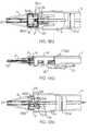
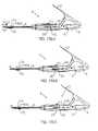
- FIG. 15( a )is a side view of an embodiment of a fastener delivery tool, showing a cartridge being loaded into the loading chamber of the device.
- FIG. 15( b )is a side view of the fastener delivery tool shown in FIG. 15( a ), showing the cartridge retainer being advanced in the distal direction (see arrow in FIG. 15( b )) over the cartridge.
- FIG. 15( c )is a side view of the fastener delivery tool shown in FIG. 15( a ), showing the fastener being transferred from the cartridge to the distal tip of the fastener delivery tool by actuation of the lever.
- FIG. 15( d )is a side view of the fastener delivery tool shown in FIG. 15( a ), showing compression of the ejection spring by additional actuation of the lever.
- FIG. 15( e )is a side view of the fastener delivery tool shown in FIG. 15( a ), showing the fastener delivery tool being fully loaded and ready to deploy the fastener.
- FIGS. 16( a ) and 16 ( b )are top and side views, respectively, showing exemplary configurations for an elongated distal tip for a fastener delivery tool.
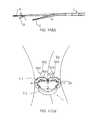
- FIG. 17( a )is a cross-sectional view of a patient's body, showing a prosthetic valve secured within a tissue annulus by exemplary fasteners.
- FIG. 17( b )is a cross-sectional view of a patient's body, showing a fastener delivery tool delivering a fastener through a portion of a prosthetic valve into the surrounding tissue.
- FIG. 17( c )is a radiograph showing a plurality of fasteners deployed about the circumference of a prosthetic valve.
- FIG. 18is an alternative embodiment of a fastener delivery tool that houses a plurality of fasteners.
- FIGS. 19( a ) and 19 ( b )are side views of another embodiment of a fastener delivery tool, showing a lever on a handle on the tool in unloaded and loaded positions, respectively.
- FIGS. 20( a ) and 20 ( b )are side views of the tool of FIGS. 19( a ) and 19 ( b ), respectively, with a cover removed to show internal components of the handle.
- FIG. 21( a )is a perspective view of a front end of the tool of FIGS. 19( a ) and 19 ( b ).
- FIGS. 21( b ) and 21 ( c )are cross-sectional side views of the front end of the tool shown in FIG. 21( a ), showing left and right sides, respectively.
- FIG. 22is a perspective view of an alternate embodiment of a fastener delivery tool including a pneumatic actuator.
- FIGS. 23( a )- 23 ( c )are side and top views of the tool of FIG. 22 .
- FIGS. 24( a ) and 24 ( b )are top views of the tool of FIG. 22 with a cover removed to show a cartridge assembly carrying fasteners therein.
- FIGS. 25( a ) and 25 ( b )are details of the tool of FIGS. 24( a ) and 24 ( b ) showing a firing button being locked out to prevent latch actuation and engaged to permit latch actuation, respectively.
- FIGS. 26( a ) and 26 ( b )are details of a front end of the tool of FIG. 22 with a cover mounted over and removed from the front end, respectively, showing fasteners being carried within the front end.
- FIGS. 27( a )- 27 ( c )are additional details of the front end of the tool of FIG. 22 .
- FIGS. 28( a ) and 28 ( b )are perspective views of a distal end that may be provided on the fastener delivery tools of FIGS. 19( a )- 21 ( c ) or FIGS. 22-27( c ).
- FIG. 28( c )is a detail of the distal end of FIG. 28( a ), showing a plurality of fasteners carried by a belt.
- FIGS. 29( a ) and 29 ( b )are side and perspective views, respectively, of a belt assembly that may be mounted in the distal end shown in FIGS. 28( a )- 28 ( c ).
- FIG. 29( c )is a detail of the belt assembly of FIG. 29( a ).
- FIG. 30is a top view of an exemplary embodiment of a pair of belts that may be included in the belt assembly of FIGS. 29( a )- 29 ( c ).
- FIGS. 31( a ) and 31 ( b )are top and side views, respectively, of another exemplary embodiment of a belt that may be included in a belt assembly, showing alternative embodiments of clip features for receiving legs of a fastener carried by the belt assembly.
- FIG. 31( c )is a cross-section through the belt of FIG. 31( a ), taken along line 31 ( c )- 31 ( c ).
- FIG. 32is a top view of a pair of belts, similar to the embodiment of FIGS. 31( a )- 31 ( c ) carrying a plurality of fasteners.
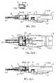
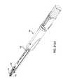
- FIG. 1shows a first embodiment of a fastener delivery tool 2 .
- the fastener delivery tool 2includes a distal tip 4 or snout from which one or more fastener(s) 6 (described in more detail below) may be ejected and a proximal end 8 that may be grasped by a user during positioning and/or delivery of the fastener 6 .
- the distal tip 4 and proximal end 8 of the tool 2are separated by an elongated shaft 9 .
- the fastener 6may be stored within a cartridge 7 that may be loaded into the fastener delivery tool 2 .
- the fastener delivery tool 2also includes a proximally located handle 10 having a lever 12 or other actuator that may be used to deploy the fastener(s) 6 .
- the handle 10may be ergonomically shaped such that a user may easily manipulate the fastener delivery tool 2 into position.
- the handle 10preferably includes a spring-biased trigger 14 , e.g., a depressible button that may be used to eject the fastener 6 from the distal tip 4 of the tool 2 .
- a cartridge retainer 16is provided on the shaft 9 that may be movable along the axial direction of the shaft 9 . As described more fully below, the cartridge retainer 16 may be used to retain or otherwise secure the cartridge 7 for subsequent deployment steps of the fastener 6 . In addition, the cartridge retainer 16 may transform the fastener 6 into a partially constrained or tensioned state.
- FIGS. 2( a ) and 2 ( b )illustrate the distal end of the fastener delivery tool 2 .
- a fastener 6may be pre-loaded in a cartridge 7 , e.g., in a parent or relaxed state. In the relaxed state, the fastener 6 may include a pair of overlapping tines 6 ( a ), 6 ( b ) (best seen in FIG. 2( b )) that may be angled with respect to one another.
- the fastener 6further includes a loop portion 6 ( c ), e.g., defined by ends of the tines 6 ( a ), 6 ( b ).
- the fastener 6may be formed from an elastic or superelastic material, such as a Nickel-Titanium alloy (Nitinol). Additional information on exemplary embodiments of fasteners that may be delivered using the tool 2 are disclosed in application Ser. Nos. 10/681,700, filed Oct. 8, 2003, and 11/004,445, filed Dec. 3, 2004, the entire disclosures of which are expressly incorporated by reference herein.
- an elastic or superelastic materialsuch as a Nickel-Titanium alloy (Nitinol). Additional information on exemplary embodiments of fasteners that may be delivered using the tool 2 are disclosed in application Ser. Nos. 10/681,700, filed Oct. 8, 2003, and 11/004,445, filed Dec. 3, 2004, the entire disclosures of which are expressly incorporated by reference herein.
- the fastener 6may be secured or otherwise retained in a groove 7 ( a ) or slot in the cartridge 7 .
- the cartridge 7 containing the fastener 6may be inserted (in the direction of arrow A in FIG. 2( a )) into a loading chamber 18 located at the distal end of the shaft 9 .
- the loop portion 6 ( c ) of the fastener 6may be lowered over a pin or other retaining member 20 .
- the retaining member 20may be movable between an engaged state (shown in FIG. 2( b )) and a disengaged state (described in more detail below).
- the retaining member 20may be biased in the engaged state by a spring 22 or other biasing mechanism.
- the retaining member 20advantageously secures the fastener 6 within the tool 2 during the process of transforming the fastener 6 from the relaxed, parent state to the constrained state (e.g., a U-shaped configuration).
- the distal tip 4 of the tool 2includes an ejection track 23 .
- the ejection track 23is connected to or otherwise communicates with the loading chamber 18 .
- the tines 6 ( a ), 6 ( b )may be forced into the U-shaped configuration and the fastener 6 may be advanced from the loading chamber 18 and into the ejection track 23 (described in more detail below).
- FIGS. 3( a ) and 3 ( b )illustrate the next step involved in deploying the fastener 6 .
- the cartridge retainer 16may be advanced distally (shown by arrow B in FIG. 3( a )).
- the cartridge retainer 16may be advanced manually, for example, by depressing a finger on ridge 16 ( a ).
- the cartridge retainer 16may also be advanced automatically, for example, through movement of the handle 10 .
- the cartridge retainer 16is coupled to a spreader 24 that may engage the tines 6 ( a ), 6 ( b ) of the fastener 6 .
- the spreader 24may include a slot or groove in which the fastener tines 6 ( a ), 6 ( b ) may be received. Movement of the cartridge retainer 16 from the position shown in FIGS. 3( a ) and 3 ( b ) to the position shown in FIGS. 4( a ) and 4 ( b ) causes the spreader 24 also to move distally. The spreader 24 contacts the tines 6 ( a ), 6 ( b ) of the fastener 6 and causes the fastener 6 to transform into a partially constrained state (best shown in FIG. 4( b ).
- FIGS. 5( a ) and 5 ( b )illustrate the tongue 26 advancing in the direction of arrow C shown in FIG. 5( b ).
- the tongue 26includes one or more teeth 26 ( a ).
- the tongue 26is advanced in the direction of arrow C and the one or more teeth 26 ( a ) drop within the loop 6 ( c ) of the fastener 6 ( c ).
- FIGS. 5( a ) and 5 ( b )illustrate the teeth 26 ( a ) within the fastener loop 6 ( c ).
- the tongue 26is advanced further in the distal direction as shown in FIGS.
- the U-shaped configurationis obtained by forcibly parting the tines 6 ( a ), 6 ( b ) of the fastener 6 using the teeth 26 ( a ) of the tongue 26 , while restraining the proximal end or loop portion 6 ( c ) of the fastener 6 , e.g., using retaining member 20 .
- FIGS. 7( a ) and 7 ( b )illustrate the fastener 6 being advanced through the ejection track 23 .
- the retaining member 20may be moved from the engaged state to the disengaged state.
- FIG. 7( a )illustrates the retaining member 20 in the disengaged state.
- the fastener 6may be free to move distally down the ejection track 23 .
- the retaining member 20is moved from the engaged state to the disengaged state by interaction of a cam structure 20 ( a ) located on the retaining member 20 with a pusher member 30 (see FIG. 7( a )).
- the cam structure 20 ( a ) on the retaining member 20may rest within a corresponding groove 30 ( a ) in the pusher member 30 .
- the cam structure 20 ( a )is forced out of the groove 30 ( a ) and forces the retaining member 20 to the disengaged state.
- the pusher member 30contacts a proximal end of the fastener 6 and pushes or advances the fastener 6 down the ejection track 23 .
- the pusher member 30continues to advance the fastener 6 until the fastener 6 reaches a position within the ejection track 23 shown in FIGS. 7( a ) and 7 ( b ). In this position, the fastener 6 is positioned such that the tines 6 ( a ), 6 ( b ) project slightly from the distal-most end of the tool 2 .
- This configurationmay permit a physician or other user to probe areas of tissue for the optimal insertion location.
- the physicianmay probe an area of tissue that may be calcified or plaque-laden and not suitable for placement of a fastener 6 .
- the physicianmay move instead to another more potentially desirable location adjacent the calcified location.
- the fastener 6may be completely ejected from the tool 2 , e.g., by depressing the trigger 14 (shown, for example, in FIG. 15( e )).
- FIGS. 8( a ) and 8 ( b )illustrate partial top and side views, respectively, of the fastener delivery tool 2 with the handle 10 and lever 12 removed for clarity.
- the loading chamber 18 of the deviceis empty and the cartridge retainer 16 is withdrawn in the proximal direction, permitting loading of another cartridge 7 carrying a fastener 6 into the tool 2 .
- FIGS. 9( a ) and 9 ( b )illustrate a fastener delivery tool 2 loaded with a single fastener 6 (the cartridge 7 is hidden simply for the sake of clarity).
- the fastener 6is in the relaxed or parent state.
- the cartridge retainer 16is then advanced distally to partially constrain the fastener 6 within the spreader 24 (shown in FIG. 10( a )).
- additional depression of the lever 12 on the handle 10advances the tongue 26 such that the teeth 26 ( a ) drop into the loop portion 6 ( c ) of the fastener (shown best in FIG. 11( b )).
- the tongue 26is fixedly coupled to a trigger assembly 32 that may be translated distally as the lever 12 on the handle is depressed.
- the trigger assembly 32is biased against an advancement mechanism 34 coupled to the actuating lever 12 .
- Actuation of the lever 12causes the advancement mechanism 34 to displace distally. This distal displacement is translated to the trigger assembly 32 via a spring 36 .
- the spring 36may be substantially stiff such that it acts as a rigid linkage between the advancement mechanism 34 and trigger assembly 32 before the compression stage (discussed in detail below). Translation of the advancement mechanism 34 and trigger assembly 32 (and coupled tongue 26 ) before the compression stage may be best seen in FIGS. 11( a ), 11 ( b ), 12 ( a ), and 12 ( b ).
- the fastener 6is then transformed into the fully constrained state (i.e., U-shaped configuration) by advancing the tongue 26 distally, e.g., by partially depressing the handle 10 of the tool 2 .
- the teeth 26 ( a ) of the tongue 26may advance between the tines 6 ( a ), 6 ( b ) of the fastener 6 to direct the fastener 6 into the U-shaped configuration.
- the fastener 6may still be retained by retaining member 20 .
- FIGS. 13( a ) and 13 ( b )illustrate the trigger assembly 32 abutting and pushing against a clamp 38 that is fixedly coupled to the pusher member 30 . Movement of the clamp 38 distally causes corresponding distal movement of the pusher member 30 within the tool 2 . The pusher member 30 then advances distally such that the cam 20 ( a ) on the retaining member 20 exits the groove 30 ( a ) in the pusher member, thereby moving the retaining member 20 to the disengaged position. Additional advancement of the handle 12 pushes the fastener 6 down the ejection track 23 of the tool. During this phase of deployment, both the tongue 26 and pusher member 30 move distally in unison. Advancement of the fastener 6 may stop when the tines 6 ( a ), 6 ( b ) project just beyond the distal-most end of the tool 2 (as shown in FIGS. 13( a ) and 13 ( b ).
- FIGS. 14( a ) and 14 ( b )illustrate ejection of the fastener 6 from the tool 2 .
- depression of the trigger 14(illustrated by arrow D in FIG. 14( b )) causes the pusher member 30 to move rapidly in the distal direction to eject the fastener 6 completely from the ejection track 23 .
- the fastener 6may be ejected in the U-shaped configuration into the adjacent tissue (not shown).
- the tool 2may also include a proximally located restoring spring 40 to aid in restoring the mechanical linkages (e.g., tongue 26 , pusher member 30 and associated trigger assembly 32 and advancement mechanism 34 ) after the fastener 6 has been ejected from the tool 2 .
- a proximally located restoring spring 40to aid in restoring the mechanical linkages (e.g., tongue 26 , pusher member 30 and associated trigger assembly 32 and advancement mechanism 34 ) after the fastener 6 has been ejected from the tool 2 .
- FIGS. 15( a ) through 15 ( e )illustrate the various stages of an exemplary method that may be used to deliver a fastener 6 using the fastener delivery tool 2 .
- FIG. 15( a )illustrates a cartridge 7 carrying a fastener 6 being loaded into the loading chamber 18 of the tool 2 .
- FIG. 15( b )illustrates the cartridge retainer 16 being moved distally (in the direction of the arrow in FIG. 15( b )). This movement of the cartridge retainer 16 advances the spreader 24 (not shown in FIG. 15) to place the fastener 6 in a partially constrained state.
- FIG. 15( c )shows the handle 10 being depressed partially.
- the teeth 26 ( a ) of the tongue 26drop into the loop portion of the fastener 6 and advance further distally to transform the fastener 6 into the U-shaped configuration, as described above. Additional movement of the handle 10 transfers the fastener 6 from the loading chamber 18 to the ejection track 23 in the distal tip 4 of the tool 2 .
- FIG. 15( d )illustrates the compression or load-driving step whereby movement of the actuating lever 12 in the direction of the arrow A shown in FIG. 15( d ) causes compression of spring 36 , also as described above.
- FIG. 15( e )illustrates the tool 2 in the fully loaded state.
- the fastener 6is disposed at the distal tip 4 of the tool 2 with the tines 6 ( a ), 6 ( b ) projecting distally from the ejection track 23 .
- the spring-loaded trigger 14is then depressed to eject the fastener 6 completely from the tool 2 .
- FIGS. 16( a ) and 16 ( b )illustrate alternative configurations, A, B, and C, for an elongated distal tip or snout 4 of the tool 2 .
- the tool 2may include distal tips 4 of varying lengths in order to facilitate the delivery process.
- the tips 4may have lengths between about ten and four hundred millimeters (10-400 mm), or between about five and fifty millimeters (5-50 mm).
- the tips 4may be integrally formed with the tool 2 .
- the tips 4may be removable and/or interchangeable.
- the tips 4 and/or tool 2may include one or more detents or other connectors (not shown) for removably attaching an individual tip 4 to the tool 2 .
- the elongated distal tip or snout 4may include a variety of geometries or side-profiles, e.g., bends or curves, to increase a user's field of view and/or otherwise facilitate delivering a fastener.
- a tip 4 and/or tool 2may be selected given the particular anatomical presentations encountered during a procedure.
- tip A shown in FIG. 16( b )illustrates a configuration in which the elongated distal tip 4 has a substantially straight or flat profile.
- Tip Billustrates another configuration in which an intermediate portion of the distal tip 4 is bent or curved out of the plane of the tool 2 .
- the bent or curved configurationmay be particularly helpful in delivering the fastener 6 generally normal or perpendicular to the surface of the surrounding tissue 90 .
- Tip Cillustrates another configuration in which the distal tip 4 is angled with respect to the longitudinal direction of the tool 2 .
- tool 2which may be any of the embodiments described herein, may be used to deliver one or more fasteners 6 , e.g., during a heart valve replacement procedure.
- the tool 2may be used to deliver a plurality of fasteners 6 through a sewing cuff or ring 51 (see FIG. 17 *(b)) and/or other component of a prosthetic heart valve assembly 50 into surrounding tissue.
- the tool 2may be used to deliver one or more fasteners 6 , e.g., to secure other devices to tissue or to another device, or to secure tissue structures together.
- the prosthetic valve 50may be a multiple component prosthesis, e.g., including a gasket member 52 , which may include a sewing cuff 51 , and a valve member or “crown” 53 , including a frame and a plurality of leaflets (not shown for simplicity).
- a gasket member 52which may include a sewing cuff 51
- a valve member or “crown” 53including a frame and a plurality of leaflets (not shown for simplicity).
- Exemplary embodiments of single or multiple component prosthetic heart valve assemblies that may be implanted and/or otherwise attached using the tool 2are disclosed in U.S. Pat. No. 6,371,983 and in U.S. Publication Nos. 2004/0122516, filed as Ser. No. 10/327,821, 2005/0043760, filed as Ser. No. 10/646,639, 2005/0165479, filed as Ser. No.
- the gasket member 52may be advanced into a biological annulus 90 , e.g., using a separate tool (not shown), and maintained at a desired location, e.g., at a site from which native valve leaflets have been removed.
- the distal tip 4 of the tool 2(loaded with a fastener 6 ) may be placed against the sewing cuff 51 with the tip 4 substantially perpendicular to the sewing cuff 51 .
- the tool 2may be actuated, e.g., by activating the lever 12 and/or trigger 14 , to deliver the fastener 6 through the sewing cuff 51 into the underlying tissue.
- the tines of the fastener 6may at least partially recross within the tissue, thereby capturing a portion of the sewing cuff 51 and the underlying tissue within the loop of the fastener 6 .
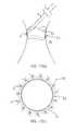
- a plurality of fasteners 6may be successively delivered about a circumference of the sewing cuff 51 to affix the prosthetic valve 50 to the surrounding tissue 90 .
- FIG. 17( a )illustrates two exemplary fasteners 6 in the fully deployed state.
- the fasteners 6may be biased to revert towards the parent or unconstrained state (in which the tines of the fasteners 6 at least partially overlap).
- the prosthetic valve 50may be fixedly secured to the surrounding tissue 90 .
- FIG. 17( c )illustrates an exemplary image or “radiograph” from a radiography device (not shown), illustrating a plurality of fasteners 6 deployed about the circumference of the prosthetic valve 50 .
- the fasteners 6 and a portion of the gasket member 52are at least partially radiopaque, and may be seen on a radiograph, while the sewing cuff 51 (shown in phantom in FIG. 17( c )) may be substantially radiolucent, and therefore not visible on the radiograph.
- the fasteners 6may be removable from tissue 90 and/or prosthetic valve 50 , e.g., if it is desired to remove the valve 50 or relocate a particular fastener.
- a pliers-like tool(not shown) may be used to remove a fastener after ejection of the fastener 6 from the tool 2 , e.g., if the fastener 6 is oriented incorrectly or the fastener 6 does not penetrate deeply enough into the tissue 90 .
- the physicianmay grasp the loop portion 6 ( c ) of the fastener 6 , which may remain at least partially exposed, using the pliers-like tool.
- the fastener 6may then be pulled or otherwise retracted proximally to remove the tines of the fastener 6 from the delivery site.
- the toolmay be rotated to at least partially open the tines of the fastener 6 to facilitate removal.
- a replacement fastener 6may be loaded into the tool 2 and/or otherwise delivered to the delivery site, similar to the methods described above.
- a toolmay be provided that may accommodate loading multiple fasteners 6 into the tool 2 simultaneously or successively before delivery. Such a tool 2 may be desirable because the tool 2 does not have to be removed from the body cavity to load successive fasteners 6 , which may accelerate delivery of the fasteners 6 .
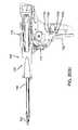
- FIG. 18illustrates an embodiment of a tool 2 , showing a plurality of fasteners 6 loaded into a staging area or section 42 . The fasteners 6 may be advanced successively in the distal direction toward the distal tip 4 of the tool 2 .
- a cartridge(not shown) may be provided that holds a plurality of fasteners 6 such that the tool 2 may be loaded with multiple fasteners 6 simply by loading a single cartridge into the tool 2 .
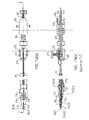
- FIGS. 19( a )- 21 ( c )another embodiment of a fastener delivery tool 102 is shown that may be used to deliver one or more fasteners (not shown), similar to previous embodiments.
- the tool 102generally includes a handle 110 including a lever 112 and trigger 114 , shown in FIGS. 19( a )- 20 ( b ), and an elongate shaft 109 terminating in a distal tip 104 , similar to the previous embodiments.
- the tool 102may include one or more internal components similar to the previous embodiments, e.g., retaining member (not shown), spreader (not shown), a tongue 126 , pusher member (not shown), and/or ejection track 123 within the elongate shaft 109 and/or distal tip 104 .
- the tool 102may include a cartridge, track, and/or other carrier (not shown), which may carry a plurality of fasteners, as described further below.
- the tool 102may include two separate subassemblies that may be removably coupled to one another.
- FIGS. 21( a )- 21 ( c )show a carriage housing 103 that may be separate from the handle 110 , yet may be inserted into the handle 110 to couple the actuating components of the carriage housing 103 with the lever 102 and trigger 104 .
- the carriage housing 103 and handle 110may include one or more cooperating connectors for securing the carriage housing 103 to the handle 110 , e.g., in the proper orientation to coupled to allow the lever 112 and trigger 114 to actuate the tool 102 .
- FIG. 21( a )- 21 ( c )show a carriage housing 103 that may be separate from the handle 110 , yet may be inserted into the handle 110 to couple the actuating components of the carriage housing 103 with the lever 102 and trigger 104 .
- the carriage housing 103 and handle 110may include one or more cooperating connectors for securing the carriage housing
- the carriage housing 103may include one or more tabs 119 a that may be received in corresponding slots 119 b in the handle 110 to secure carriage housing 103 to the handle 110 .
- the connectorsmay allow the carriage housing 103 to be removed from the handle 110 , e.g., after all of the fasteners therein have been delivered, and then a new carriage housing (not shown) may then be coupled to the handle 110 to deliver additional fasteners, if desired.
- the carriage housing 103 and handle 110may be substantially permanently attached to one another.
- the components of the carriage housing 103may be coupled to one or more of the lever 112 and/or trigger 114 , similar to the embodiments described elsewhere herein.
- the lever 112may be generally configured similar to the lever 12 and the trigger 114 may be generally configured similar to the trigger 14 , shown and described with reference to FIGS. 15( a )- 15 ( e ).
- the lever 112may be in an unloaded position, e.g., similar to the position of lever 12 shown in FIG. 15( c ).
- the lever 112has been depressed to load a fastener, e.g., from a cartridge or other carrier (not shown) within the elongate shaft 109 .
- actuation of the lever 112may remove a fastener from a cartridge, track, or other carrier, deform the fastener from a relaxed to a constrained configuration, and advance the fastener such that tines of the fastener are exposed (not shown) from the distal tip 104 , similar to the sequence shown in FIGS. 9( a )- 13 ( b ).
- the lever 112may include a latch 113 b that may be engaged by a spring or other catch 113 a within the handle 104 to maintain the lever 112 in the loaded position.
- the lever 112may be locked with the tips of a fastener exposed, e.g., similar to the configuration shown in FIGS. 13( a ) and 13 ( b ). This may facilitate a user manipulating the tool 102 before delivering a fastener, e.g., to test and/or otherwise identify an appropriate target location for delivering the fastener, as described elsewhere herein.
- the lever 112may be coupled to one or more ratcheted wheels 112 a , 112 b , which may be coupled, in turn, to the actuating components of the tool 102 via ratchet bar 112 c , e.g., for loading a fastener into a loading chamber, deforming the fastener from the relaxed configuration to the U-shaped configuration, and/or for advancing the fastener down the ejection track 123 .
- the lever 112may be coupled via the wheel 112 a and ratchet bar 112 c to a drive plate 116 , which may be advanced distally when the lever 112 is actuated.
- the drive plate 116includes a plurality of slots 116 a - 116 c that include arms coupled to the actuating components of the tool 102 .
- slot 116 amay receive arm 117 a , which may be coupled to an advancer arm 192 , which may be used to advance a belt assembly or other track (not shown), as explained further below.
- Slot 116 bmay slidably receive 117 b , which may be coupled to the pusher member (not shown), and slot 116 c may receive arm 117 c , which may be coupled to the spreader (not shown).
- Another slot (not shown)may be provided on the drive plate 116 that may receive an arm (also not shown) coupled to the tongue (not shown).
- the drive plate 116When the lever 112 is actuated, the drive plate 116 may be directed distally within the carriage assembly 103 , thereby directing the arms distally until cams drop the arms out of vertical portions of the slots 116 a - 116 c and into horizontal portions thereof.
- the sequence of the slots 116 a - 116 c and arms 117may function similarly to the sequence described in the previous embodiments.
- the trigger 114may be actuated similar to the trigger 14 , as described elsewhere herein.
- a spring(not shown) may be compressed, similar to spring 36 shown in FIGS. 13( a )- 14 ( b ), to store potential energy.
- a lock 121may engage to prevent the energy from the spring being released.
- the trigger 114is actuated, the lock 121 may be released, and the spring may rapidly advance the pusher member (not shown) to eject the fastener from the tool 102 , similar to the action of the pusher member 30 described above.
- actuation of the trigger 114may “reset” the tool 102 , e.g., in preparation for loading and delivering another fastener.
- a latch 113 cmay engage a cam 114 to release the spring 113 from the latch 113 b , thereby allowing the lever 112 to return to its original position.
- the front end of the tool 102may include a cover or other housing (not shown), e.g., over the elongate shaft 109 and/or distal tip 104 .
- the covermay provide a desired aesthetic finish to the tool 102 and/or may protect the interior components.
- the covermay provide access to the interior of the elongate shaft 109 , e.g., to remove and/or load a cartridge or other carrier (not shown in FIGS. 21( a )- 21 ( c )) into the tool 102 , as described further below.
- the tool 102may allow multiple fasteners to be delivered successively using the tool 102 without having to reload individual fasteners.
- the cover or housing on the elongate shaft 109may be opened or otherwise removed to allow a belt assembly or other cartridge (not shown, carrying a plurality of fasteners) to be loaded into the tool 102 .
- the covermay be opened to allow individual fasteners to be loaded onto a belt or other track (not shown) in the elongate shaft 109 .
- the covermay not be removable; in this alternative, the tool 102 may included a belt assembly or track pre-loaded with a plurality of fasteners that may delivered with the tool 102 . Once the supply of fasteners is depleted, the tool 102 may be discarded or returned to the manufacturer for reloading.
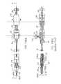
- FIGS. 22-27( c )another embodiment of a tool 202 is shown that includes a handle 210 , an elongate shaft 209 , and a distal tip 204 (including actuating components therein), which may include similar components to the other embodiments described herein.
- the tool 202includes an air cylinder 213 for actuating the tool 202 , e.g., to load and/or fire one or more fasteners successively using the tool 202 .
- FIG. 23( a )- 23 ( c )show additional details of the tool 202 , e.g., including a trigger, firing button or other actuator 212 on the handle 210 that may be used to activate the air cylinder 213 to deliver a fastener from the tool 202 .
- the firing button 212may completely deliver a fastener upon activation of the trigger 212 .
- the firing button 212(or separate actuators, not shown) may allow a two-stage delivery, e.g., loading and partially exposing a fastener upon initial actuation, and then releasing the fastener upon final actuation, similar to the previous embodiments.
- a compressed air, carbon dioxide, or other fluid linemay be coupled to a connector 213 a on the air cylinder 213 to at least partially actuate the tool 202 .
- the fluid linemay include a pedal, valve, or other actuator, which may be opened to deliver fluid into the air cylinder 213 . This action causes the tool 212 to load a fastener from the cartridge or track, deform the tool, and advance the fastener down the ejector track 223 , similar to the lever 112 .
- the firing button 212may be depressed to eject the fastener. The user may then open the fluid line again to load the next fastener for delivery.
- any pneumatic or hydraulic systemmay be used to load the fasteners.
- the fluid linemay automatically load a fastener without requiring the user to activate the fluid line.
- a self-contained compressed fluid devicemay be provided in the handle 210 of the tool 202 , which may be activated or may automatically load a fastener.
- the tool 202may include a reusable portion, i.e., the handle 210 , and a disposable portion, i.e., a carriage housing 207 that may be loaded into the handle 210 for providing a plurality of fasteners (not shown) to be delivered by the tool 202 .
- the handle 210includes a cover 260 over a housing 270 that includes the internal actuating components of the handle 210 , e.g., coupling the firing button 212 to the air cylinder 213 .
- the housing 270may be movable axially within the cover 260 , e.g., between a first or “locked out” position, shown in FIG. 24( a ) and a second or “active” position, shown in FIG. 24( b ).
- a spring 268may be provided between the housing 266 and the cover 260 for biasing the housing 270 to the locked out position, yet the bias may be overcome when the carriage housing 207 is loaded into the handle 210 .
- the carriage housing 207includes a proximal housing 208 , e.g., including a drive plate (not shown) or other actuating components, the elongate shaft 209 , and distal tip 204 of the tool 202 , which may include an ejection track 223 , retaining member, spreader, tongue, and/or pusher member (all not shown), which may operate generally similar to the previous embodiments.
- the cover 260may include an open end opposite the air cylinder 213 into which the carriage housing 207 may be inserted to couple the actuating components of the carriage housing 207 to the handle 210 .
- the elongate shaft 209 and distal tip 204may be part of the handle 210 and a belt assembly or other cartridge assembly (not shown) may be loaded directly into the elongate shaft 209 and/or proximal housing 208 .
- the handle 210may include features to ensure that the carriage housing 207 is properly loaded into and/or otherwise coupled to the handle 210 .
- FIGS. 25( a ) and 25 ( b )show a lever arm 262 that includes a pivotable end 262 a and a free end 262 b underlying the firing button 212 .
- the free end 262 b of the lever arm 262abuts a hub 264 on the housing 270 , as shown in FIG. 25( a ).
- the firing button 212cannot be depressed because the lever arm 262 cannot be directed inwardly.
- the housing 270As the carriage housing 207 is loaded into the housing 270 , i.e., inserted in the direction of arrow “L” shown in FIG. 24( b ), the housing 270 is displaced axially against the bias of the spring 268 , thereby directing the hub 264 proximally from under the free end 262 b of the lever arm 262 .
- the free end 262 b of the lever arm 262may overly the latch 272 , as shown in FIG. 25( b ).
- the lever arm 262may pivot inwardly until the free end 262 b contacts and pushes the latch 272 , allowing fasteners to be delivered from the tool 202 .
- the firing button 212may be locked out, e.g., preventing fasteners from moving within and/or being delivered from the tool 202 and/or otherwise risking damage to the tool 202 and/or injury to the user due to accidental activation of the air cylinder 213 .
- the carriage housing 207 and handle 210may include cooperating connectors (not shown) that may secure the carriage housing 207 to the housing 270 and/or that secure the housing 270 in the active position relative to the cover 210 .
- the carriage housing 207 and handle 210may include tab 219 a and slot 219 b , similar to the previous embodiments.
- the internal actuating components of the handle 210may be coupled to the actuating components within the elongate shaft 209 of the carriage housing 207 .
- the connectorsmay be released, returning the handle 210 to the locked out position.
- FIGS. 26( a )- 28 ( c )the elongate shaft 209 of the tool 202 is shown in more detail.
- the elongate shaft 209includes a belt assembly 280 for carrying a plurality of fasteners 6 to the loading chamber 218 in the distal tip 204 of the tool 202 .
- FIG. 26( a )shows the elongate shaft 209 with a cover 274 attached over the belt assembly 280 (and other internal components), while FIG. 26( b ) shows the cover 274 removed to expose the belt assembly 280 .
- FIGS. 26( a )shows the elongate shaft 209 with a cover 274 attached over the belt assembly 280 (and other internal components), while FIG. 26( b ) shows the cover 274 removed to expose the belt assembly 280 .
- the elongate shaft 209includes a rigid elongate base or chassis 209 a defining a channel 209 b that extends from a first end of the carriage housing 207 (received in the housing 270 ) to the distal tip 204 .
- An ejection track 223e.g., including a pair of spaced-apart rails having a “C” shaped cross-section, extends from the loading chamber 218 for guiding the fasteners 6 during delivery.
- a retaining pin 220is provided in the loading chamber 218 for receiving each fastener 6 successively from the belt assembly 280 , as described further below.
- a spreader, tongue, and pusher member(not shown) are also provided within the elongate shaft 209 and/or distal end 204 that operate generally similar to the previous embodiments.
- the belt assembly 280generally includes a frame 282 and a pair of belts 284 movable relative to the frame 282 .
- the frame 282includes a first end 282 a , which may be disposed within the chassis 209 a (e.g., nearest the housing 270 , as shown in FIGS. 27( b ) and 27 ( c )), and a second end 282 b , which may be disposed adjacent the distal tip 204 and/or loading chamber 218 .
- the frame 282may be substantially secured within the channel 209 b of the chassis 209 a , e.g., using one or more cooperating connectors (not shown), bonding with adhesive, interference fit, and the like, such that the frame 282 remains substantially stationary during use.
- Each belt 284may be an endless band or loop received around hubs (not shown) on the first and second ends 282 a , 282 b of the frame 282 .
- the belts 284may be free to move, e.g., such that upper surfaces of the belts 284 may be directed distally towards the loading chamber 218 , while simultaneously lower surfaces of the belts 284 are directed proximally away from the loading chamber 218 .
- the hubsmay include wheels or other features on axles (not shown) to facilitate movement of the belts 284 .
- each belt 284 and/or the hubs of the frame 284may be formed from material minimizing friction between the belts 284 and the hubs, e.g., including a lubricious coating or material, such that the belts 284 may slide easily around the hubs.
- each belt 284may made from a strip of substantially inelastic material, e.g., a metal, polymer, and/or composite material, having sufficient flexibility to be curved around the ends 282 a , 282 b of the frame 282 and having sufficient length such that ends of the strip may be attached to one another, e.g., by bonding with adhesive, sonic welding, mating connectors (not shown), and the like, to create the band or loop.
- a single beltmay be provided that extends across the width of the frame 282 , rather than separate belts 284 .
- the beltmay be made from one or two strips (not shown) having a first end fixed to a track supported by the frame 282 below the loading chamber 218 and a second end fixed to the track adjacent the first end 282 a of the frame 282 .
- Each of the belts 284include features for receiving a portion of fasteners 6 loaded onto the belt assembly 280 , e.g., to releasably carry the fasteners 6 along the belt assembly 280 to the loading chamber 218 of the tool 202 .
- each belt 284includes a plurality of hooks 286 for receiving tines 6 ( a ), 6 ( b ) of respective fasteners 6 .
- the hooks 286may be formed directly in the belt material, e.g., by injection molding, machining, and the like, or may be separate from the belts 284 and attached thereto, e.g., by bonding with adhesive, sonic welding, cooperating connectors (not shown), and the like.
- the hooks 286may define a recess sized for receiving the tines 6 ( a ), 6 ( b ) therein, e.g., the hooks 286 extending at least about one hundred eight degrees (180°) around the recess.
- the hooks 286may be sufficiently flexible to allow the tines 6 ( a ), 6 ( b ) to be released from the recesses when a loop portion 6 ( c ) is received around the retaining pin 220 , e.g., when the first fastener 6 on the belt assembly 280 is advanced into the loading chamber 218 .
- the ejector track 223may include ramped proximal edges to guide the fastener 6 from the belts 284 onto the retaining pin 220 .
- the belts 284may be advanced by an actuator coupled to the handle 210 .
- a cross-bar 290may be attached between the belts 284 , e.g., thereby coupling movement of the belts 284 together.
- the cross-bar 290may maintain the hooks 286 in adjacent pairs to ensure that individual fasteners 6 may be releasably captured by respective pairs of hooks 286 .
- a pushrod 292may be coupled to the cross-bar 290 , e.g., to advance the belts 284 with each actuation of the tool 202 .
- the pushrod 292may be advanced initially to direct the first fastener 6 into the loading chamber 218 , e.g., such that the loop portion 6 ( c ) is received on the retaining pin 220 (see FIG. 28( c ).
- the fastener 6may be deformed into the U-shaped configuration and advanced down the ejector track 223 (or 123 ), similar to the previous embodiments.
- the pushrod 292may be advanced sufficiently to deliver the next fastener 6 into the loading chamber 218 and/or onto the retaining pin 220 .
- the pushrodmay be retracted and advanced between fasteners.
- an advancer arm 192may be provided within the tool 102 , e.g., within the carriage housing 103 of FIGS. 21( b ) and 21 ( c ) or within the proximal housing 208 of FIG. 22 .
- the advancer armthat may include a tip 192 a that may contact elements on a track 194 to which the pushrod 292 is coupled to advance the fasteners.
- the tip 192 amay contact blunt edges of recesses 194 a in the track 194 during advancement, and may slide proximally over the recesses 194 a during retraction.
- the advancer arm 192may be advanced a predetermined distance corresponding to the spacing of the fasteners on the belts, and the tip 192 a may engage the immediately adjacent recess 194 a to advance the track 194 .
- the track 194in turn advances the pushrod 292 , which advances the belts 284 , e.g., shown in FIGS. 27( a )- 27 ( c ).
- the lever 112may then deform and advance the fastener down the ejector track 123 .
- the advancer arm 192may be retracted immediately after pushing the lever 112 or after actuating the trigger 114 , thereby pulling the tip 192 a back adjacent the next recess 194 a in the track 194
- the track 194may be advanced incrementally, advancing the pushrod and belts 284 .
- a belt assemblymay be provided in a disposable (or reusable) assembly that may be coupled to a handle or other actuator, such as the carriage housing 207 described above for the tool 202 .
- a belt assemblymay be provided within a tool that cannot be reloaded. For example, if the carriage housing 103 is not removable from the tool 102 , after the fasteners are all delivered, the entire tool 102 may be discarded or reused (e.g., by returning the tool 102 to the manufacturer who may sterilize and reload the tool 102 with new fasteners).
- chassis or elongate shaftmay include a cover that may be removed or otherwise opened to allow a belt assembly to be replaced or to allow individual fasteners to be loaded on a belt assembly.
- the frame of the belt assembly and/or the elongate shaftmay include one or more connectors for removably securing the belt assembly within the elongate shaft. Otherwise, operation of this alternative may proceed similar to the other embodiments described herein.
- each belt 384is an elongate strip that may be wrapped around hubs on a frame, similar to the belts 284 described above.
- Each belt 384includes features 386 a , 386 b that may be folded up to receive tines 6 ( a ), 6 ( b ) of fasteners 6 thereunder.
- each belt 384may include partial loops or “J” hooks 386 a that may be lifted to be received over and/or around the tines 6 ( a ), 6 ( b ).
- the “J” hooks 386 amay be disposed along edges of the belts 384 nearest each other to receive a middle portion of the tines 6 ( a ), 6 ( b ) thereunder.
- Each belt 384may also include tabs 386 b with slots or holes to receive the tips of the tines 6 ( a ), 6 ( b ), e.g., along edges of the belts 384 away from each other.
- Each belt 384may be formed from a thin film, e.g., by laser cutting, stamping, mechanically cutting, and the like, such that the features 386 a , 386 b are formed directly in the film with the respective belts 384 . Any other features needed for each belt 384 may also be formed directly in the film, e.g., holes or slots for connecting ends of the belt 384 together after wrapping the belt 384 around the frame of the belt assembly.
- the belt 484includes a band 485 , e.g., made from a metal, plastic, or composite material sufficiently flexible to be movably mounted around a frame of a belt assembly, similar to the previous embodiments.
- the band 485may be laser cut, stamped, mechanically cut, molded, and the like to include spaced-apart openings 487 therein for receiving features 486 a , 486 b .
- the features 486 a , 486 bmay be clips, e.g., formed from plastic, metal, or composite materials, that may be attached to the band 485 , e.g., in respective holes 487 .
- the clip 486 amay be inserted into hole 487 and secured therein, e.g., by heat-stake, bonding with adhesive, sonic welding, press-fit, and the like.
- the clip 486 b(which may be used instead of the clip 486 a in a belt 484 ) may be snapped into the hole 487 or secured similar to clip 486 a.
- a pair of belts 484may be provided, e.g., in a belt assembly (not shown) for carrying a plurality of fasteners 6 , similar to the previous embodiments.
- the clips 486 a , 486 bmay be aligned in pairs for receiving respective tines 6 ( a ), 6 ( b ) of fasteners 6 , e.g., within recesses or slots in the clips 486 a , 486 b .
- the slots in the clips 486 a , 486 bmay extend substantially vertically, i.e., upwardly away from the bands 485 . Otherwise, the clips 486 a , 486 b and hooks 286 may be used similarly to one another.
- any of the features described hereinshould substantially securely hold the fasteners carried by the belt assembly, e.g., to prevent the fasteners from coming loose during normal operation of the delivery tool.
- the featuresshould allow the fasteners to be released easily from the belt assembly as they are delivered into the loading chamber, e.g., without risk of jamming the tool.
- the materials of the belt assembly contacting the fastenersbe non-metallic, e.g., to reduce the risk of damaging the fasteners while being carried by the belt assembly.
- the components contacting the fastenerssuch as the belts themselves and/or the features capturing the tines, from PEEK, e.g., PEEK Classix. This may reduce the risk of the belt scratching or otherwise creating any surface defects in the fasteners.
Landscapes
- Health & Medical Sciences (AREA)
- Life Sciences & Earth Sciences (AREA)
- Surgery (AREA)
- Heart & Thoracic Surgery (AREA)
- Engineering & Computer Science (AREA)
- Biomedical Technology (AREA)
- Nuclear Medicine, Radiotherapy & Molecular Imaging (AREA)
- Medical Informatics (AREA)
- Molecular Biology (AREA)
- Animal Behavior & Ethology (AREA)
- General Health & Medical Sciences (AREA)
- Public Health (AREA)
- Veterinary Medicine (AREA)
- Surgical Instruments (AREA)
- Prostheses (AREA)
Abstract
Description
Claims (30)
Priority Applications (4)
| Application Number | Priority Date | Filing Date | Title |
|---|---|---|---|
| US12/115,543US8147504B2 (en) | 2007-05-05 | 2008-05-05 | Apparatus and methods for delivering fasteners during valve replacement |
| EP09743503.6AEP2291126B1 (en) | 2008-05-05 | 2009-05-05 | Apparatus and for delivering fasteners |
| PCT/US2009/042895WO2009137517A1 (en) | 2008-05-05 | 2009-05-05 | Apparatus and methods for delivering fasteners during valve replacement |
| JP2011508611AJP5571656B2 (en) | 2008-05-05 | 2009-05-05 | Apparatus and method for delivering fasteners during valve replacement |
Applications Claiming Priority (2)
| Application Number | Priority Date | Filing Date | Title |
|---|---|---|---|
| US91628307P | 2007-05-05 | 2007-05-05 | |
| US12/115,543US8147504B2 (en) | 2007-05-05 | 2008-05-05 | Apparatus and methods for delivering fasteners during valve replacement |
Publications (2)
| Publication Number | Publication Date |
|---|---|
| US20090036903A1 US20090036903A1 (en) | 2009-02-05 |
| US8147504B2true US8147504B2 (en) | 2012-04-03 |
Family
ID=40902844
Family Applications (1)
| Application Number | Title | Priority Date | Filing Date |
|---|---|---|---|
| US12/115,543Active2030-10-14US8147504B2 (en) | 2007-05-05 | 2008-05-05 | Apparatus and methods for delivering fasteners during valve replacement |
Country Status (4)
| Country | Link |
|---|---|
| US (1) | US8147504B2 (en) |
| EP (1) | EP2291126B1 (en) |
| JP (1) | JP5571656B2 (en) |
| WO (1) | WO2009137517A1 (en) |
Cited By (38)
| Publication number | Priority date | Publication date | Assignee | Title |
|---|---|---|---|---|
| US20110224785A1 (en)* | 2010-03-10 | 2011-09-15 | Hacohen Gil | Prosthetic mitral valve with tissue anchors |
| US8852272B2 (en) | 2011-08-05 | 2014-10-07 | Mitraltech Ltd. | Techniques for percutaneous mitral valve replacement and sealing |
| US8870950B2 (en) | 2009-12-08 | 2014-10-28 | Mitral Tech Ltd. | Rotation-based anchoring of an implant |
| US8992604B2 (en) | 2010-07-21 | 2015-03-31 | Mitraltech Ltd. | Techniques for percutaneous mitral valve replacement and sealing |
| US9017399B2 (en) | 2010-07-21 | 2015-04-28 | Mitraltech Ltd. | Techniques for percutaneous mitral valve replacement and sealing |
| US9333073B2 (en) | 2009-04-15 | 2016-05-10 | Edwards Lifesciences Cardiaq Llc | Vascular implant and delivery method |
| US9339377B2 (en) | 2008-09-29 | 2016-05-17 | Edwards Lifesciences Cardiaq Llc | Body cavity prosthesis |
| US9554897B2 (en) | 2011-04-28 | 2017-01-31 | Neovasc Tiara Inc. | Methods and apparatus for engaging a valve prosthesis with tissue |
| US9572665B2 (en) | 2013-04-04 | 2017-02-21 | Neovasc Tiara Inc. | Methods and apparatus for delivering a prosthetic valve to a beating heart |
| US9597183B2 (en) | 2008-10-01 | 2017-03-21 | Edwards Lifesciences Cardiaq Llc | Delivery system for vascular implant |
| US9681951B2 (en) | 2013-03-14 | 2017-06-20 | Edwards Lifesciences Cardiaq Llc | Prosthesis with outer skirt and anchors |
| US9681952B2 (en) | 2013-01-24 | 2017-06-20 | Mitraltech Ltd. | Anchoring of prosthetic valve supports |
| US9707005B2 (en) | 2014-02-14 | 2017-07-18 | Ethicon Llc | Lockout mechanisms for surgical devices |
| US9713529B2 (en) | 2011-04-28 | 2017-07-25 | Neovasc Tiara Inc. | Sequentially deployed transcatheter mitral valve prosthesis |
| US9763657B2 (en) | 2010-07-21 | 2017-09-19 | Mitraltech Ltd. | Techniques for percutaneous mitral valve replacement and sealing |
| US9770329B2 (en) | 2010-05-05 | 2017-09-26 | Neovasc Tiara Inc. | Transcatheter mitral valve prosthesis |
| USD800908S1 (en) | 2016-08-10 | 2017-10-24 | Mitraltech Ltd. | Prosthetic valve element |
| US9974651B2 (en) | 2015-02-05 | 2018-05-22 | Mitral Tech Ltd. | Prosthetic valve with axially-sliding frames |
| US10016275B2 (en) | 2012-05-30 | 2018-07-10 | Neovasc Tiara Inc. | Methods and apparatus for loading a prosthesis onto a delivery system |
| USD841812S1 (en) | 2017-08-03 | 2019-02-26 | Cardiovalve Ltd. | Prosthetic heart valve element |
| US10245143B2 (en) | 2011-08-05 | 2019-04-02 | Cardiovalve Ltd. | Techniques for percutaneous mitral valve replacement and sealing |
| US10376361B2 (en) | 2011-08-05 | 2019-08-13 | Cardiovalve Ltd. | Techniques for percutaneous mitral valve replacement and sealing |
| US10390952B2 (en) | 2015-02-05 | 2019-08-27 | Cardiovalve Ltd. | Prosthetic valve with flexible tissue anchor portions |
| US10492908B2 (en) | 2014-07-30 | 2019-12-03 | Cardiovalve Ltd. | Anchoring of a prosthetic valve |
| US10531866B2 (en) | 2016-02-16 | 2020-01-14 | Cardiovalve Ltd. | Techniques for providing a replacement valve and transseptal communication |
| US10575948B2 (en) | 2017-08-03 | 2020-03-03 | Cardiovalve Ltd. | Prosthetic heart valve |
| US10583002B2 (en) | 2013-03-11 | 2020-03-10 | Neovasc Tiara Inc. | Prosthetic valve with anti-pivoting mechanism |
| US10856975B2 (en) | 2016-08-10 | 2020-12-08 | Cardiovalve Ltd. | Prosthetic valve with concentric frames |
| US10888421B2 (en) | 2017-09-19 | 2021-01-12 | Cardiovalve Ltd. | Prosthetic heart valve with pouch |
| US11246704B2 (en) | 2017-08-03 | 2022-02-15 | Cardiovalve Ltd. | Prosthetic heart valve |
| US11291547B2 (en) | 2011-08-05 | 2022-04-05 | Cardiovalve Ltd. | Leaflet clip with collars |
| US11382746B2 (en) | 2017-12-13 | 2022-07-12 | Cardiovalve Ltd. | Prosthetic valve and delivery tool therefor |
| US11633277B2 (en) | 2018-01-10 | 2023-04-25 | Cardiovalve Ltd. | Temperature-control during crimping of an implant |
| US11653910B2 (en) | 2010-07-21 | 2023-05-23 | Cardiovalve Ltd. | Helical anchor implantation |
| US11793633B2 (en) | 2017-08-03 | 2023-10-24 | Cardiovalve Ltd. | Prosthetic heart valve |
| US12029646B2 (en) | 2017-08-03 | 2024-07-09 | Cardiovalve Ltd. | Prosthetic heart valve |
| US12053379B2 (en) | 2016-08-01 | 2024-08-06 | Cardiovalve Ltd. | Minimally-invasive delivery systems |
| US12357459B2 (en) | 2020-12-03 | 2025-07-15 | Cardiovalve Ltd. | Transluminal delivery system |
Families Citing this family (101)
| Publication number | Priority date | Publication date | Assignee | Title |
|---|---|---|---|---|
| US6613059B2 (en) | 1999-03-01 | 2003-09-02 | Coalescent Surgical, Inc. | Tissue connector apparatus and methods |
| US8118822B2 (en)* | 1999-03-01 | 2012-02-21 | Medtronic, Inc. | Bridge clip tissue connector apparatus and methods |
| US6926730B1 (en)* | 2000-10-10 | 2005-08-09 | Medtronic, Inc. | Minimally invasive valve repair procedure and apparatus |
| US6551332B1 (en) | 2000-03-31 | 2003-04-22 | Coalescent Surgical, Inc. | Multiple bias surgical fastener |
| US8366769B2 (en) | 2000-06-01 | 2013-02-05 | Edwards Lifesciences Corporation | Low-profile, pivotable heart valve sewing ring |
| US6409758B2 (en)* | 2000-07-27 | 2002-06-25 | Edwards Lifesciences Corporation | Heart valve holder for constricting the valve commissures and methods of use |
| US7201771B2 (en) | 2001-12-27 | 2007-04-10 | Arbor Surgical Technologies, Inc. | Bioprosthetic heart valve |
| US7959674B2 (en)* | 2002-07-16 | 2011-06-14 | Medtronic, Inc. | Suture locking assembly and method of use |
| US8066724B2 (en)* | 2002-09-12 | 2011-11-29 | Medtronic, Inc. | Anastomosis apparatus and methods |
| US8551162B2 (en) | 2002-12-20 | 2013-10-08 | Medtronic, Inc. | Biologically implantable prosthesis |
| US8021421B2 (en) | 2003-08-22 | 2011-09-20 | Medtronic, Inc. | Prosthesis heart valve fixturing device |
| US7556647B2 (en)* | 2003-10-08 | 2009-07-07 | Arbor Surgical Technologies, Inc. | Attachment device and methods of using the same |
| US7879047B2 (en)* | 2003-12-10 | 2011-02-01 | Medtronic, Inc. | Surgical connection apparatus and methods |
| US7871435B2 (en) | 2004-01-23 | 2011-01-18 | Edwards Lifesciences Corporation | Anatomically approximate prosthetic mitral heart valve |
| US20050228494A1 (en)* | 2004-03-29 | 2005-10-13 | Salvador Marquez | Controlled separation heart valve frame |
| US8574257B2 (en)* | 2005-02-10 | 2013-11-05 | Edwards Lifesciences Corporation | System, device, and method for providing access in a cardiovascular environment |
| US7513909B2 (en)* | 2005-04-08 | 2009-04-07 | Arbor Surgical Technologies, Inc. | Two-piece prosthetic valves with snap-in connection and methods for use |
| JP4912395B2 (en) | 2005-05-24 | 2012-04-11 | エドワーズ ライフサイエンシーズ コーポレイション | Rapid placement prosthetic heart valve |
| US8211169B2 (en) | 2005-05-27 | 2012-07-03 | Medtronic, Inc. | Gasket with collar for prosthetic heart valves and methods for using them |
| US7776084B2 (en)* | 2005-07-13 | 2010-08-17 | Edwards Lifesciences Corporation | Prosthetic mitral heart valve having a contoured sewing ring |
| US7967857B2 (en)* | 2006-01-27 | 2011-06-28 | Medtronic, Inc. | Gasket with spring collar for prosthetic heart valves and methods for making and using them |
| JP5102279B2 (en)* | 2006-03-10 | 2012-12-19 | メドトロニック,インコーポレイテッド | Artificial valve introducer, method for producing the same and method for using the same |
| JP2009535128A (en)* | 2006-04-29 | 2009-10-01 | アーバー・サージカル・テクノロジーズ・インコーポレイテッド | Multi-part prosthetic heart valve assembly and apparatus and method for delivering the same |
| US8021161B2 (en)* | 2006-05-01 | 2011-09-20 | Edwards Lifesciences Corporation | Simulated heart valve root for training and testing |
| US8147504B2 (en)* | 2007-05-05 | 2012-04-03 | Medtronic, Inc. | Apparatus and methods for delivering fasteners during valve replacement |
| EP2358308B1 (en) | 2008-09-15 | 2019-11-27 | Medtronic, Inc. | Tools for remodeling tissue |
| US8449625B2 (en) | 2009-10-27 | 2013-05-28 | Edwards Lifesciences Corporation | Methods of measuring heart valve annuluses for valve replacement |
| US8944990B2 (en)* | 2008-10-27 | 2015-02-03 | Ams Research Corporation | Surgical needle and anchor system with retractable features |
| EP2370138B1 (en) | 2008-11-25 | 2020-12-30 | Edwards Lifesciences Corporation | Apparatus for in situ expansion of prosthetic device |
| US8308798B2 (en) | 2008-12-19 | 2012-11-13 | Edwards Lifesciences Corporation | Quick-connect prosthetic heart valve and methods |
| US9402720B2 (en)* | 2009-01-12 | 2016-08-02 | Valve Medical Ltd. | Modular percutaneous valve structure and delivery method |
| US8801732B2 (en) | 2009-01-26 | 2014-08-12 | Ethicon Endo-Surgery, Inc. | Surgical stapler to secure a tissue fold |
| US8439244B2 (en) | 2010-01-20 | 2013-05-14 | Ethicon Endo-Surgery, Inc. | Surgical stapler fastening device with movable anvil |
| US9713471B2 (en) | 2009-01-26 | 2017-07-25 | Ethicon Endo-Surgery, Inc. | Surgical device with tandem fasteners |
| US20100187285A1 (en)* | 2009-01-26 | 2010-07-29 | Harris Jason L | Surgical stapler for applying a large staple though a small delivery port and a method of using the stapler to secure a tissue fold |
| US9713468B2 (en) | 2009-01-26 | 2017-07-25 | Ethicon Endo-Surgery, Inc. | Surgical stapler for applying a large staple through a small delivery port and a method of using the stapler to secure a tissue fold |
| US8453905B2 (en) | 2009-01-26 | 2013-06-04 | Ethicon Endo-Surgery, Inc. | Surgical fastener for applying a large staple through a small delivery port |
| US8602286B2 (en) | 2009-01-26 | 2013-12-10 | Ethicon Endo-Surgery, Inc. | Apparatus for feeding staples in a low profile surgical stapler |
| US8469252B2 (en) | 2009-01-26 | 2013-06-25 | Ethicon Endo-Surgery, Inc. | Surgical stapler fastening device with adjustable anvil |
| US9980818B2 (en) | 2009-03-31 | 2018-05-29 | Edwards Lifesciences Corporation | Prosthetic heart valve system with positioning markers |
| US8579920B2 (en) | 2009-05-12 | 2013-11-12 | Ethicon, Inc. | Surgical fasteners, applicator instruments, and methods for deploying surgical fasteners |
| USD698021S1 (en) | 2009-05-12 | 2014-01-21 | Ethicon, Inc. | Surgical fastener |
| USD744646S1 (en) | 2009-05-12 | 2015-12-01 | Ethicon, Inc. | Surgical fastener |
| US8894669B2 (en) | 2009-05-12 | 2014-11-25 | Ethicon, Inc. | Surgical fasteners, applicator instruments, and methods for deploying surgical fasteners |
| US8728099B2 (en)* | 2009-05-12 | 2014-05-20 | Ethicon, Inc. | Surgical fasteners, applicator instruments, and methods for deploying surgical fasteners |
| US9055945B2 (en) | 2009-05-12 | 2015-06-16 | Ethicon, Inc. | Surgical fasteners having articulating joints and deflectable tips |
| US8728098B2 (en)* | 2009-05-12 | 2014-05-20 | Ethicon, Inc. | Surgical fasteners, applicator instruments, and methods for deploying surgical fasteners |
| US8920439B2 (en)* | 2009-05-12 | 2014-12-30 | Ethicon, Inc. | Applicator instruments having curved and articulating shafts for deploying surgical fasteners and methods therefor |
| US8348998B2 (en) | 2009-06-26 | 2013-01-08 | Edwards Lifesciences Corporation | Unitary quick connect prosthetic heart valve and deployment system and methods |
| US9345473B2 (en) | 2009-12-30 | 2016-05-24 | Astora Women's Health, Llc | Implantable sling systems and methods |
| US8986374B2 (en) | 2010-05-10 | 2015-03-24 | Edwards Lifesciences Corporation | Prosthetic heart valve |
| US9554901B2 (en) | 2010-05-12 | 2017-01-31 | Edwards Lifesciences Corporation | Low gradient prosthetic heart valve |
| US9370418B2 (en) | 2010-09-10 | 2016-06-21 | Edwards Lifesciences Corporation | Rapidly deployable surgical heart valves |
| US8641757B2 (en) | 2010-09-10 | 2014-02-04 | Edwards Lifesciences Corporation | Systems for rapidly deploying surgical heart valves |
| US9125741B2 (en) | 2010-09-10 | 2015-09-08 | Edwards Lifesciences Corporation | Systems and methods for ensuring safe and rapid deployment of prosthetic heart valves |
| US8845720B2 (en) | 2010-09-27 | 2014-09-30 | Edwards Lifesciences Corporation | Prosthetic heart valve frame with flexible commissures |
| CN102743201B (en)* | 2011-04-20 | 2014-03-12 | 苏州天臣国际医疗科技有限公司 | Linear cutting suturing device |
| US8945209B2 (en) | 2011-05-20 | 2015-02-03 | Edwards Lifesciences Corporation | Encapsulated heart valve |
| US9078747B2 (en) | 2011-12-21 | 2015-07-14 | Edwards Lifesciences Corporation | Anchoring device for replacing or repairing a heart valve |
| US8992547B2 (en) | 2012-03-21 | 2015-03-31 | Ethicon Endo-Surgery, Inc. | Methods and devices for creating tissue plications |
| US9693862B2 (en) | 2012-07-31 | 2017-07-04 | Edwards Lifesciences Corporation | Holders for prosthetic heart valves |
| US11007058B2 (en) | 2013-03-15 | 2021-05-18 | Edwards Lifesciences Corporation | Valved aortic conduits |
| WO2014145811A1 (en) | 2013-03-15 | 2014-09-18 | Edwards Lifesciences Corporation | Valved aortic conduits |
| US9468527B2 (en) | 2013-06-12 | 2016-10-18 | Edwards Lifesciences Corporation | Cardiac implant with integrated suture fasteners |
| US9919137B2 (en) | 2013-08-28 | 2018-03-20 | Edwards Lifesciences Corporation | Integrated balloon catheter inflation system |
| EP3046512B1 (en) | 2013-09-20 | 2024-03-06 | Edwards Lifesciences Corporation | Heart valves with increased effective orifice area |
| US20150122687A1 (en) | 2013-11-06 | 2015-05-07 | Edwards Lifesciences Corporation | Bioprosthetic heart valves having adaptive seals to minimize paravalvular leakage |
| US9539005B2 (en) | 2013-11-08 | 2017-01-10 | C.R. Bard, Inc. | Surgical fastener deployment system |
| US9782200B2 (en)* | 2014-02-09 | 2017-10-10 | Payam Andalib | Neuromonitoring needle-cartridge gun system |
| US9549816B2 (en) | 2014-04-03 | 2017-01-24 | Edwards Lifesciences Corporation | Method for manufacturing high durability heart valve |
| US9585752B2 (en) | 2014-04-30 | 2017-03-07 | Edwards Lifesciences Corporation | Holder and deployment system for surgical heart valves |
| USD867594S1 (en) | 2015-06-19 | 2019-11-19 | Edwards Lifesciences Corporation | Prosthetic heart valve |
| CA2914094C (en) | 2014-06-20 | 2021-01-05 | Edwards Lifesciences Corporation | Surgical heart valves identifiable post-implant |
| WO2016022797A1 (en) | 2014-08-06 | 2016-02-11 | Edwards Lifesciences Corporation | Multi-lumen cannulae |
| CN104490445B (en)* | 2014-12-12 | 2016-10-05 | 浙江微度医疗器械有限公司 | A kind of packing box for loading hemostatic clamp in cartridge clip |
| CN107920894B (en) | 2015-07-02 | 2020-04-28 | 爱德华兹生命科学公司 | Integrated hybrid heart valve |
| CA2989437C (en) | 2015-07-02 | 2023-08-08 | Edwards Lifesciences Corporation | Hybrid heart valves adapted for post-implant expansion |
| CN108135592B (en) | 2015-09-02 | 2021-05-14 | 爱德华兹生命科学公司 | Spacer for securing a transcatheter valve to a bioprosthetic cardiac structure |
| US10080653B2 (en) | 2015-09-10 | 2018-09-25 | Edwards Lifesciences Corporation | Limited expansion heart valve |
| CA3007660A1 (en) | 2015-12-15 | 2017-06-22 | Neovasc Tiara Inc. | Transseptal delivery system |
| US10433952B2 (en) | 2016-01-29 | 2019-10-08 | Neovasc Tiara Inc. | Prosthetic valve for avoiding obstruction of outflow |
| US10667904B2 (en) | 2016-03-08 | 2020-06-02 | Edwards Lifesciences Corporation | Valve implant with integrated sensor and transmitter |
| US10456245B2 (en) | 2016-05-16 | 2019-10-29 | Edwards Lifesciences Corporation | System and method for applying material to a stent |
| CA3042588A1 (en) | 2016-11-21 | 2018-05-24 | Neovasc Tiara Inc. | Methods and systems for rapid retraction of a transcatheter heart valve delivery system |
| USD846122S1 (en) | 2016-12-16 | 2019-04-16 | Edwards Lifesciences Corporation | Heart valve sizer |
| US10463485B2 (en) | 2017-04-06 | 2019-11-05 | Edwards Lifesciences Corporation | Prosthetic valve holders with automatic deploying mechanisms |
| EP3614969B1 (en) | 2017-04-28 | 2023-05-03 | Edwards Lifesciences Corporation | Prosthetic heart valve with collapsible holder |
| WO2018237020A1 (en) | 2017-06-21 | 2018-12-27 | Edwards Lifesciences Corporation | CARDIAC EXPANDED CARDIAC VALVES IN THE FORM OF DOUBLE THREAD |
| CA3073834A1 (en) | 2017-08-25 | 2019-02-28 | Neovasc Tiara Inc. | Sequentially deployed transcatheter mitral valve prosthesis |
| EP3694562A2 (en) | 2017-10-13 | 2020-08-19 | Edwards Lifesciences Corporation | Method for sterilizing heart valves |
| EP3743016B1 (en) | 2018-01-23 | 2024-10-02 | Edwards Lifesciences Corporation | Prosthetic valve holders, systems, and methods |
| USD908874S1 (en) | 2018-07-11 | 2021-01-26 | Edwards Lifesciences Corporation | Collapsible heart valve sizer |
| CN113271890B (en) | 2018-11-08 | 2024-08-30 | 内奥瓦斯克迪亚拉公司 | Ventricular deployment of transcatheter mitral valve prosthesis |
| WO2020163145A1 (en) | 2019-02-05 | 2020-08-13 | Edwards Lifesciences Corporation | Prosthetic heart valve with suture loop preventing member |
| CA3132873A1 (en) | 2019-03-08 | 2020-09-17 | Neovasc Tiara Inc. | Retrievable prosthesis delivery system |
| CA3135753C (en) | 2019-04-01 | 2023-10-24 | Neovasc Tiara Inc. | Controllably deployable prosthetic valve |
| US11491006B2 (en) | 2019-04-10 | 2022-11-08 | Neovasc Tiara Inc. | Prosthetic valve with natural blood flow |
| US11779742B2 (en) | 2019-05-20 | 2023-10-10 | Neovasc Tiara Inc. | Introducer with hemostasis mechanism |
| JP7520897B2 (en) | 2019-06-20 | 2024-07-23 | ニオバスク ティアラ インコーポレイテッド | Thin prosthetic mitral valve |
| WO2021025979A1 (en) | 2019-08-02 | 2021-02-11 | Edwards Lifesciences Corporation | Rotary application of fibrous material to medical devices |
| CR20210655A (en) | 2019-12-16 | 2022-06-02 | Edwards Lifesciences Corp | Valve holder assembly with suture looping protection |
Citations (43)
| Publication number | Priority date | Publication date | Assignee | Title |
|---|---|---|---|---|
| US4086926A (en)* | 1976-10-08 | 1978-05-02 | United States Surgical Corporation | Ligating and dividing organic structures |
| US4246903A (en)* | 1979-04-02 | 1981-01-27 | American Cyanamid Company | Surgical instrument to apply a hemostatic clip to a vessel and method of using the same |
| US4496090A (en)* | 1982-03-10 | 1985-01-29 | Crevier Paul H | Surgical stapler |
| US4509518A (en)* | 1982-02-17 | 1985-04-09 | United States Surgical Corporation | Apparatus for applying surgical clips |
| US4637395A (en)* | 1983-10-04 | 1987-01-20 | Aesculap-Werke Ag | Applicator for C-shaped scalp clips |
| US4671278A (en)* | 1985-01-14 | 1987-06-09 | Thomas J. Fogarty | Scalp hemostatic clip and dispenser therefor |
| US4821721A (en)* | 1985-01-14 | 1989-04-18 | Thomas J. Fogarty | Apparatus and method for applying hemostatic scalp clips |
| US4854317A (en)* | 1987-02-16 | 1989-08-08 | Aesculap-Werke Ag Vormals Jetter & Scheerer | Applicator for C-shaped scalp clips |
| US4874122A (en)* | 1986-07-14 | 1989-10-17 | Minnesota Mining And Manufacturing Company | Bent back box staple and staple closing mechanism with split actuator |
| US4899745A (en)* | 1988-04-14 | 1990-02-13 | Laboureau Jacques Philippe | Surgical clip for cutaneous suture and tool for applying it |
| US4983176A (en)* | 1989-03-06 | 1991-01-08 | University Of New Mexico | Deformable plastic surgical clip |
| US5035692A (en)* | 1990-02-13 | 1991-07-30 | Nicholas Herbert | Hemostasis clip applicator |
| US5192288A (en)* | 1992-05-26 | 1993-03-09 | Origin Medsystems, Inc. | Surgical clip applier |
| US5207692A (en)* | 1990-07-30 | 1993-05-04 | Codman & Shurtleff, Inc. | Surgical clip applier with reciprocating clip sleeve and dual ratchet mechanism |
| US5242457A (en)* | 1992-05-08 | 1993-09-07 | Ethicon, Inc. | Surgical instrument and staples for applying purse string sutures |
| US5269792A (en)* | 1992-05-26 | 1993-12-14 | Origin Medsystems, Inc. | Surgical clip |
| US5413584A (en)* | 1992-05-11 | 1995-05-09 | Ethicon, Inc. | "Omega"-shaped staple for surgical, especially endoscopic, purposes |
| US5425489A (en)* | 1990-12-20 | 1995-06-20 | United States Surgical Corporation | Fascia clip and instrument |
| US5439468A (en)* | 1993-05-07 | 1995-08-08 | Ethicon Endo-Surgery | Surgical clip applier |
| US5456400A (en)* | 1993-04-22 | 1995-10-10 | United States Surgical Corporation | Apparatus and clip for fastening body tissue |
| US5542949A (en)* | 1987-05-14 | 1996-08-06 | Yoon; Inbae | Multifunctional clip applier instrument |
| US5618311A (en)* | 1994-09-28 | 1997-04-08 | Gryskiewicz; Joseph M. | Surgical subcuticular fastener system |
| US5626585A (en)* | 1994-09-16 | 1997-05-06 | United States Surgical Corporation | Ligating clip advance |
| US5674231A (en)* | 1995-10-20 | 1997-10-07 | United States Surgical Corporation | Apparatus and method for vascular hole closure |
| US5715987A (en)* | 1994-04-05 | 1998-02-10 | Tracor Incorporated | Constant width, adjustable grip, staple apparatus and method |
| US5843097A (en)* | 1996-02-03 | 1998-12-01 | Aesculap Ag | Surgical applicator |
| US6352541B1 (en)* | 1997-11-26 | 2002-03-05 | Aesculap Ag & Co. Kg | Magazine for a surgical clip applicator |
| US20020087169A1 (en)* | 1998-02-24 | 2002-07-04 | Brock David L. | Flexible instrument |
| US6464710B1 (en)* | 1995-03-06 | 2002-10-15 | Cook Urological Incorporated | Releasable, surgical clamp |
| US6702826B2 (en)* | 2000-06-23 | 2004-03-09 | Viacor, Inc. | Automated annular plication for mitral valve repair |
| US6767356B2 (en)* | 2000-09-01 | 2004-07-27 | Angiolink Corporation | Advanced wound site management systems and methods |
| US6837895B2 (en)* | 1999-07-23 | 2005-01-04 | Aesculap Ag & Co. Kg | Instrument for placing surgical clips |
| US20050080454A1 (en)* | 2003-10-08 | 2005-04-14 | Drews Michael J. | Attachment device and methods of using the same |
| US20050107871A1 (en)* | 2003-03-30 | 2005-05-19 | Fidel Realyvasquez | Apparatus and methods for valve repair |
| US20050107810A1 (en)* | 2002-06-13 | 2005-05-19 | Guided Delivery Systems, Inc. | Devices and methods for heart valve repair |
| US7056330B2 (en)* | 2002-05-31 | 2006-06-06 | Ethicon Endo-Surgery, Inc. | Method for applying tissue fastener |
| US20060122634A1 (en)* | 2004-12-03 | 2006-06-08 | Ino Takashi H | Apparatus and method for delivering fasteners during valve replacement |
| US7179265B2 (en)* | 2001-08-21 | 2007-02-20 | Microline Pentax, Inc. | Reduced diameter clip applying arrangement |
| US7344544B2 (en)* | 2005-03-28 | 2008-03-18 | Cardica, Inc. | Vascular closure system |
| US7473258B2 (en)* | 2007-03-08 | 2009-01-06 | Cardica, Inc. | Surgical stapler |
| US7533790B1 (en)* | 2007-03-08 | 2009-05-19 | Cardica, Inc. | Surgical stapler |
| US7572266B2 (en)* | 2003-10-21 | 2009-08-11 | Young Wayne P | Clip applier tool having a discharge configuration |
| US7594920B2 (en)* | 1999-11-29 | 2009-09-29 | General Surgical Innovations, Inc. | Blood vessel clip and applicator |
Family Cites Families (2)
| Publication number | Priority date | Publication date | Assignee | Title |
|---|---|---|---|---|
| US4127227A (en)* | 1976-10-08 | 1978-11-28 | United States Surgical Corporation | Wide fascia staple cartridge |
| US8147504B2 (en)* | 2007-05-05 | 2012-04-03 | Medtronic, Inc. | Apparatus and methods for delivering fasteners during valve replacement |
- 2008
- 2008-05-05USUS12/115,543patent/US8147504B2/enactiveActive
- 2009
- 2009-05-05EPEP09743503.6Apatent/EP2291126B1/enactiveActive
- 2009-05-05WOPCT/US2009/042895patent/WO2009137517A1/enactiveApplication Filing
- 2009-05-05JPJP2011508611Apatent/JP5571656B2/enactiveActive
Patent Citations (48)
| Publication number | Priority date | Publication date | Assignee | Title |
|---|---|---|---|---|
| US4086926A (en)* | 1976-10-08 | 1978-05-02 | United States Surgical Corporation | Ligating and dividing organic structures |
| US4246903A (en)* | 1979-04-02 | 1981-01-27 | American Cyanamid Company | Surgical instrument to apply a hemostatic clip to a vessel and method of using the same |
| US4509518A (en)* | 1982-02-17 | 1985-04-09 | United States Surgical Corporation | Apparatus for applying surgical clips |
| US4624254A (en)* | 1982-02-17 | 1986-11-25 | United States Surgical Corporation | Apparatus for applying surgical clips |
| US4496090A (en)* | 1982-03-10 | 1985-01-29 | Crevier Paul H | Surgical stapler |
| US4637395A (en)* | 1983-10-04 | 1987-01-20 | Aesculap-Werke Ag | Applicator for C-shaped scalp clips |
| US4671278A (en)* | 1985-01-14 | 1987-06-09 | Thomas J. Fogarty | Scalp hemostatic clip and dispenser therefor |
| US4821721A (en)* | 1985-01-14 | 1989-04-18 | Thomas J. Fogarty | Apparatus and method for applying hemostatic scalp clips |
| US4874122A (en)* | 1986-07-14 | 1989-10-17 | Minnesota Mining And Manufacturing Company | Bent back box staple and staple closing mechanism with split actuator |
| US4854317A (en)* | 1987-02-16 | 1989-08-08 | Aesculap-Werke Ag Vormals Jetter & Scheerer | Applicator for C-shaped scalp clips |
| US5542949A (en)* | 1987-05-14 | 1996-08-06 | Yoon; Inbae | Multifunctional clip applier instrument |
| US4899745A (en)* | 1988-04-14 | 1990-02-13 | Laboureau Jacques Philippe | Surgical clip for cutaneous suture and tool for applying it |
| US4983176A (en)* | 1989-03-06 | 1991-01-08 | University Of New Mexico | Deformable plastic surgical clip |
| US5035692A (en)* | 1990-02-13 | 1991-07-30 | Nicholas Herbert | Hemostasis clip applicator |
| US5207692A (en)* | 1990-07-30 | 1993-05-04 | Codman & Shurtleff, Inc. | Surgical clip applier with reciprocating clip sleeve and dual ratchet mechanism |
| US5425489A (en)* | 1990-12-20 | 1995-06-20 | United States Surgical Corporation | Fascia clip and instrument |
| US5242457A (en)* | 1992-05-08 | 1993-09-07 | Ethicon, Inc. | Surgical instrument and staples for applying purse string sutures |
| US5413584A (en)* | 1992-05-11 | 1995-05-09 | Ethicon, Inc. | "Omega"-shaped staple for surgical, especially endoscopic, purposes |
| US5269792A (en)* | 1992-05-26 | 1993-12-14 | Origin Medsystems, Inc. | Surgical clip |
| US5282808A (en)* | 1992-05-26 | 1994-02-01 | Origin Medsystems, Inc. | Closure prevention apparatus for surgical clip applier |
| US5192288A (en)* | 1992-05-26 | 1993-03-09 | Origin Medsystems, Inc. | Surgical clip applier |
| US5547474A (en)* | 1992-05-26 | 1996-08-20 | Origin Medsystems, Incorporated | Surgical clip closure apparatus with safety stop |
| US5456400A (en)* | 1993-04-22 | 1995-10-10 | United States Surgical Corporation | Apparatus and clip for fastening body tissue |
| US5439468A (en)* | 1993-05-07 | 1995-08-08 | Ethicon Endo-Surgery | Surgical clip applier |
| US5715987A (en)* | 1994-04-05 | 1998-02-10 | Tracor Incorporated | Constant width, adjustable grip, staple apparatus and method |
| US5626585A (en)* | 1994-09-16 | 1997-05-06 | United States Surgical Corporation | Ligating clip advance |
| US5618311A (en)* | 1994-09-28 | 1997-04-08 | Gryskiewicz; Joseph M. | Surgical subcuticular fastener system |
| US6464710B1 (en)* | 1995-03-06 | 2002-10-15 | Cook Urological Incorporated | Releasable, surgical clamp |
| US5674231A (en)* | 1995-10-20 | 1997-10-07 | United States Surgical Corporation | Apparatus and method for vascular hole closure |
| US5843097A (en)* | 1996-02-03 | 1998-12-01 | Aesculap Ag | Surgical applicator |
| US6352541B1 (en)* | 1997-11-26 | 2002-03-05 | Aesculap Ag & Co. Kg | Magazine for a surgical clip applicator |
| US20020087169A1 (en)* | 1998-02-24 | 2002-07-04 | Brock David L. | Flexible instrument |
| US6837895B2 (en)* | 1999-07-23 | 2005-01-04 | Aesculap Ag & Co. Kg | Instrument for placing surgical clips |
| US7594920B2 (en)* | 1999-11-29 | 2009-09-29 | General Surgical Innovations, Inc. | Blood vessel clip and applicator |
| US6702826B2 (en)* | 2000-06-23 | 2004-03-09 | Viacor, Inc. | Automated annular plication for mitral valve repair |
| US6767356B2 (en)* | 2000-09-01 | 2004-07-27 | Angiolink Corporation | Advanced wound site management systems and methods |
| US7179265B2 (en)* | 2001-08-21 | 2007-02-20 | Microline Pentax, Inc. | Reduced diameter clip applying arrangement |
| US7056330B2 (en)* | 2002-05-31 | 2006-06-06 | Ethicon Endo-Surgery, Inc. | Method for applying tissue fastener |
| US20050107810A1 (en)* | 2002-06-13 | 2005-05-19 | Guided Delivery Systems, Inc. | Devices and methods for heart valve repair |
| US20050107871A1 (en)* | 2003-03-30 | 2005-05-19 | Fidel Realyvasquez | Apparatus and methods for valve repair |
| US20050080454A1 (en)* | 2003-10-08 | 2005-04-14 | Drews Michael J. | Attachment device and methods of using the same |
| US7572266B2 (en)* | 2003-10-21 | 2009-08-11 | Young Wayne P | Clip applier tool having a discharge configuration |
| US20060122634A1 (en)* | 2004-12-03 | 2006-06-08 | Ino Takashi H | Apparatus and method for delivering fasteners during valve replacement |
| US20080119875A1 (en)* | 2004-12-03 | 2008-05-22 | Arbor Surgical Technologies, Inc. | Apparatus and method for delivering fasteners during valve replacement |
| US7344544B2 (en)* | 2005-03-28 | 2008-03-18 | Cardica, Inc. | Vascular closure system |
| US7744610B2 (en)* | 2005-03-28 | 2010-06-29 | Cardica, Inc. | System for closing a tissue structure from inside |
| US7473258B2 (en)* | 2007-03-08 | 2009-01-06 | Cardica, Inc. | Surgical stapler |
| US7533790B1 (en)* | 2007-03-08 | 2009-05-19 | Cardica, Inc. | Surgical stapler |
Cited By (130)
| Publication number | Priority date | Publication date | Assignee | Title |
|---|---|---|---|---|
| US9456896B2 (en) | 2008-09-29 | 2016-10-04 | Edwards Lifesciences Cardiaq Llc | Body cavity prosthesis |
| US9339377B2 (en) | 2008-09-29 | 2016-05-17 | Edwards Lifesciences Cardiaq Llc | Body cavity prosthesis |
| US9597183B2 (en) | 2008-10-01 | 2017-03-21 | Edwards Lifesciences Cardiaq Llc | Delivery system for vascular implant |
| US9339378B2 (en) | 2009-04-15 | 2016-05-17 | Edwards Lifesciences Cardiaq Llc | Vascular implant and delivery system |
| US9585747B2 (en) | 2009-04-15 | 2017-03-07 | Edwards Lifesciences Cardiaq Llc | Vascular implant |
| US9339379B2 (en) | 2009-04-15 | 2016-05-17 | Edwards Lifesciences Cardiaq Llc | Vascular implant and delivery system |
| US9333073B2 (en) | 2009-04-15 | 2016-05-10 | Edwards Lifesciences Cardiaq Llc | Vascular implant and delivery method |
| US9333074B2 (en) | 2009-04-15 | 2016-05-10 | Edwards Lifesciences Cardiaq Llc | Vascular implant and delivery system |
| US9339380B2 (en) | 2009-04-15 | 2016-05-17 | Edwards Lifesciences Cardiaq Llc | Vascular implant |
| US11351026B2 (en) | 2009-12-08 | 2022-06-07 | Cardiovalve Ltd. | Rotation-based anchoring of an implant |
| US11839541B2 (en) | 2009-12-08 | 2023-12-12 | Cardiovalve Ltd. | Prosthetic heart valve with upper skirt |
| US10231831B2 (en) | 2009-12-08 | 2019-03-19 | Cardiovalve Ltd. | Folding ring implant for heart valve |
| US10548726B2 (en) | 2009-12-08 | 2020-02-04 | Cardiovalve Ltd. | Rotation-based anchoring of an implant |
| US10610359B2 (en) | 2009-12-08 | 2020-04-07 | Cardiovalve Ltd. | Folding ring prosthetic heart valve |
| US10660751B2 (en) | 2009-12-08 | 2020-05-26 | Cardiovalve Ltd. | Prosthetic heart valve with upper skirt |
| US11141268B2 (en) | 2009-12-08 | 2021-10-12 | Cardiovalve Ltd. | Prosthetic heart valve with upper and lower skirts |
| US8870950B2 (en) | 2009-12-08 | 2014-10-28 | Mitral Tech Ltd. | Rotation-based anchoring of an implant |
| US11109964B2 (en) | 2010-03-10 | 2021-09-07 | Cardiovalve Ltd. | Axially-shortening prosthetic valve |
| US20110224785A1 (en)* | 2010-03-10 | 2011-09-15 | Hacohen Gil | Prosthetic mitral valve with tissue anchors |
| US12167963B2 (en) | 2010-03-10 | 2024-12-17 | Cardiovalve Ltd. | Method for use at a heart valve |
| US10449042B2 (en) | 2010-05-05 | 2019-10-22 | Neovasc Tiara Inc. | Transcatheter mitral valve prosthesis |
| US11419720B2 (en) | 2010-05-05 | 2022-08-23 | Neovasc Tiara Inc. | Transcatheter mitral valve prosthesis |
| US11432924B2 (en) | 2010-05-05 | 2022-09-06 | Neovasc Tiara Inc. | Transcatheter mitral valve prosthesis |
| US9770329B2 (en) | 2010-05-05 | 2017-09-26 | Neovasc Tiara Inc. | Transcatheter mitral valve prosthesis |
| US11969163B2 (en) | 2010-07-21 | 2024-04-30 | Cardiovalve Ltd. | Valve prosthesis configured for deployment in annular spacer |
| US10925595B2 (en) | 2010-07-21 | 2021-02-23 | Cardiovalve Ltd. | Valve prosthesis configured for deployment in annular spacer |
| US9132009B2 (en) | 2010-07-21 | 2015-09-15 | Mitraltech Ltd. | Guide wires with commissural anchors to advance a prosthetic valve |
| US10531872B2 (en) | 2010-07-21 | 2020-01-14 | Cardiovalve Ltd. | Valve prosthesis configured for deployment in annular spacer |
| US9017399B2 (en) | 2010-07-21 | 2015-04-28 | Mitraltech Ltd. | Techniques for percutaneous mitral valve replacement and sealing |
| US10512456B2 (en) | 2010-07-21 | 2019-12-24 | Cardiovalve Ltd. | Techniques for percutaneous mitral valve replacement and sealing |
| US12310575B2 (en) | 2010-07-21 | 2025-05-27 | Cardiovalve Ltd. | Helical anchor implantation |
| US8992604B2 (en) | 2010-07-21 | 2015-03-31 | Mitraltech Ltd. | Techniques for percutaneous mitral valve replacement and sealing |
| US11426155B2 (en) | 2010-07-21 | 2022-08-30 | Cardiovalve Ltd. | Helical anchor implantation |
| US9763657B2 (en) | 2010-07-21 | 2017-09-19 | Mitraltech Ltd. | Techniques for percutaneous mitral valve replacement and sealing |
| US11653910B2 (en) | 2010-07-21 | 2023-05-23 | Cardiovalve Ltd. | Helical anchor implantation |
| US9713529B2 (en) | 2011-04-28 | 2017-07-25 | Neovasc Tiara Inc. | Sequentially deployed transcatheter mitral valve prosthesis |
| US9554897B2 (en) | 2011-04-28 | 2017-01-31 | Neovasc Tiara Inc. | Methods and apparatus for engaging a valve prosthesis with tissue |
| US10226341B2 (en) | 2011-08-05 | 2019-03-12 | Cardiovalve Ltd. | Implant for heart valve |
| US11864995B2 (en) | 2011-08-05 | 2024-01-09 | Cardiovalve Ltd. | Implant for heart valve |
| US11517429B2 (en) | 2011-08-05 | 2022-12-06 | Cardiovalve Ltd. | Apparatus for use at a heart valve |
| US10695173B2 (en) | 2011-08-05 | 2020-06-30 | Cardiovalve Ltd. | Techniques for percutaneous mitral valve replacement and sealing |
| US10376361B2 (en) | 2011-08-05 | 2019-08-13 | Cardiovalve Ltd. | Techniques for percutaneous mitral valve replacement and sealing |
| US8852272B2 (en) | 2011-08-05 | 2014-10-07 | Mitraltech Ltd. | Techniques for percutaneous mitral valve replacement and sealing |
| US11690712B2 (en) | 2011-08-05 | 2023-07-04 | Cardiovalve Ltd. | Clip-secured implant for heart valve |
| US9387078B2 (en) | 2011-08-05 | 2016-07-12 | Mitraltech Ltd. | Percutaneous mitral valve replacement and sealing |
| US10245143B2 (en) | 2011-08-05 | 2019-04-02 | Cardiovalve Ltd. | Techniques for percutaneous mitral valve replacement and sealing |
| US11369469B2 (en) | 2011-08-05 | 2022-06-28 | Cardiovalve Ltd. | Method for use at a heart valve |
| US10702385B2 (en) | 2011-08-05 | 2020-07-07 | Cardiovalve Ltd. | Implant for heart valve |
| US11517436B2 (en) | 2011-08-05 | 2022-12-06 | Cardiovalve Ltd. | Implant for heart valve |
| US12396848B2 (en) | 2011-08-05 | 2025-08-26 | Cardiovalve Ltd. | Method for use at a heart valve |
| US11344410B2 (en) | 2011-08-05 | 2022-05-31 | Cardiovalve Ltd. | Implant for heart valve |
| US11951005B2 (en) | 2011-08-05 | 2024-04-09 | Cardiovalve Ltd. | Implant for heart valve |
| US11291545B2 (en) | 2011-08-05 | 2022-04-05 | Cardiovalve Ltd. | Implant for heart valve |
| US11291546B2 (en) | 2011-08-05 | 2022-04-05 | Cardiovalve Ltd. | Leaflet clip with collars |
| US11291547B2 (en) | 2011-08-05 | 2022-04-05 | Cardiovalve Ltd. | Leaflet clip with collars |
| US12053369B2 (en) | 2011-11-23 | 2024-08-06 | Neovasc Tiara Inc. | Sequentially deployed transcatheter mitral valve prosthesis |
| US10537422B2 (en) | 2011-11-23 | 2020-01-21 | Neovasc Tiara Inc. | Sequentially deployed transcatheter mitral valve prosthesis |
| US11413139B2 (en) | 2011-11-23 | 2022-08-16 | Neovasc Tiara Inc. | Sequentially deployed transcatheter mitral valve prosthesis |
| US12138159B2 (en) | 2012-02-14 | 2024-11-12 | Neovasc Tiara Inc. | Methods and apparatus for engaging a valve prosthesis with tissue |
| US10363133B2 (en) | 2012-02-14 | 2019-07-30 | Neovac Tiara Inc. | Methods and apparatus for engaging a valve prosthesis with tissue |
| US11497602B2 (en) | 2012-02-14 | 2022-11-15 | Neovasc Tiara Inc. | Methods and apparatus for engaging a valve prosthesis with tissue |
| US10314705B2 (en) | 2012-05-30 | 2019-06-11 | Neovasc Tiara Inc. | Methods and apparatus for loading a prosthesis onto a delivery system |
| US10940001B2 (en) | 2012-05-30 | 2021-03-09 | Neovasc Tiara Inc. | Methods and apparatus for loading a prosthesis onto a delivery system |
| US11389294B2 (en) | 2012-05-30 | 2022-07-19 | Neovasc Tiara Inc. | Methods and apparatus for loading a prosthesis onto a delivery system |
| US11617650B2 (en) | 2012-05-30 | 2023-04-04 | Neovasc Tiara Inc. | Methods and apparatus for loading a prosthesis onto a delivery system |
| US10016275B2 (en) | 2012-05-30 | 2018-07-10 | Neovasc Tiara Inc. | Methods and apparatus for loading a prosthesis onto a delivery system |
| US9681952B2 (en) | 2013-01-24 | 2017-06-20 | Mitraltech Ltd. | Anchoring of prosthetic valve supports |
| US10835377B2 (en) | 2013-01-24 | 2020-11-17 | Cardiovalve Ltd. | Rolled prosthetic valve support |
| US11844691B2 (en) | 2013-01-24 | 2023-12-19 | Cardiovalve Ltd. | Partially-covered prosthetic valves |
| US10631982B2 (en) | 2013-01-24 | 2020-04-28 | Cardiovale Ltd. | Prosthetic valve and upstream support therefor |
| US11135059B2 (en) | 2013-01-24 | 2021-10-05 | Cardiovalve Ltd. | Prosthetic valve and upstream support therefor |
| US10583002B2 (en) | 2013-03-11 | 2020-03-10 | Neovasc Tiara Inc. | Prosthetic valve with anti-pivoting mechanism |
| US9681951B2 (en) | 2013-03-14 | 2017-06-20 | Edwards Lifesciences Cardiaq Llc | Prosthesis with outer skirt and anchors |
| US11389291B2 (en) | 2013-04-04 | 2022-07-19 | Neovase Tiara Inc. | Methods and apparatus for delivering a prosthetic valve to a beating heart |
| US10383728B2 (en) | 2013-04-04 | 2019-08-20 | Neovasc Tiara Inc. | Methods and apparatus for delivering a prosthetic valve to a beating heart |
| US9572665B2 (en) | 2013-04-04 | 2017-02-21 | Neovasc Tiara Inc. | Methods and apparatus for delivering a prosthetic valve to a beating heart |
| US9707005B2 (en) | 2014-02-14 | 2017-07-18 | Ethicon Llc | Lockout mechanisms for surgical devices |
| US10842524B2 (en) | 2014-02-14 | 2020-11-24 | Ethicon Llc | Lockout mechanisms for surgical devices |
| US12053380B2 (en) | 2014-07-30 | 2024-08-06 | Cardiovalve Ltd. | Anchoring of a prosthetic valve |
| US10492908B2 (en) | 2014-07-30 | 2019-12-03 | Cardiovalve Ltd. | Anchoring of a prosthetic valve |
| US10390952B2 (en) | 2015-02-05 | 2019-08-27 | Cardiovalve Ltd. | Prosthetic valve with flexible tissue anchor portions |
| US11534298B2 (en) | 2015-02-05 | 2022-12-27 | Cardiovalve Ltd. | Prosthetic valve with s-shaped tissue anchors |
| US12396851B2 (en) | 2015-02-05 | 2025-08-26 | Cardiovalve Ltd. | Prosthetic valve with arms and flanges |
| US10888422B2 (en) | 2015-02-05 | 2021-01-12 | Cardiovalve Ltd. | Prosthetic valve with flexible tissue anchor portions |
| US10736742B2 (en) | 2015-02-05 | 2020-08-11 | Cardiovalve Ltd. | Prosthetic valve with atrial arms |
| US9974651B2 (en) | 2015-02-05 | 2018-05-22 | Mitral Tech Ltd. | Prosthetic valve with axially-sliding frames |
| US10524903B2 (en) | 2015-02-05 | 2020-01-07 | Cardiovalve Ltd. | Prosthetic valve with aligned inner and outer frames |
| US10758344B2 (en) | 2015-02-05 | 2020-09-01 | Cardiovalve Ltd. | Prosthetic valve with angularly offset frames |
| US10667908B2 (en) | 2015-02-05 | 2020-06-02 | Cardiovalve Ltd. | Prosthetic valve with S-shaped tissue anchors |
| US10682227B2 (en) | 2015-02-05 | 2020-06-16 | Cardiovalve Ltd. | Prosthetic valve with pivoting tissue anchor portions |
| US10507105B2 (en) | 2015-02-05 | 2019-12-17 | Cardiovalve Ltd. | Prosthetic valve with tissue anchors free from lateral interconnections |
| US10973636B2 (en) | 2015-02-05 | 2021-04-13 | Cardiovalve Ltd. | Prosthetic valve with tissue anchors free from lateral interconnections |
| US10463487B2 (en) | 2015-02-05 | 2019-11-05 | Cardiovalve Ltd. | Prosthetic valve delivery system with independently-movable capsule portions |
| US10463488B2 (en) | 2015-02-05 | 2019-11-05 | Cardiovalve Ltd. | Prosthetic valve with separably-deployable valve body and tissue anchors |
| US10449047B2 (en) | 2015-02-05 | 2019-10-22 | Cardiovalve Ltd. | Prosthetic heart valve with compressible frames |
| US10426610B2 (en) | 2015-02-05 | 2019-10-01 | Cardiovalve Ltd. | Prosthetic valve with radially-deflectable tissue anchors |
| US10722360B2 (en) | 2015-02-05 | 2020-07-28 | Cardiovalve Ltd. | Prosthetic valve with radially-deflectable tissue anchors |
| US10864078B2 (en) | 2015-02-05 | 2020-12-15 | Cardiovalve Ltd. | Prosthetic valve with separably-deployable valve body and tissue anchors |
| US10849748B2 (en) | 2015-02-05 | 2020-12-01 | Cardiovalve Ltd. | Prosthetic valve delivery system with independently-movable capsule portions |
| US10695177B2 (en) | 2015-02-05 | 2020-06-30 | Cardiovalve Ltd. | Prosthetic valve with aligned inner and outer frames |
| US11801135B2 (en) | 2015-02-05 | 2023-10-31 | Cardiovalve Ltd. | Techniques for deployment of a prosthetic valve |
| US10918481B2 (en) | 2015-02-05 | 2021-02-16 | Cardiovalve Ltd. | Techniques for deployment of a prosthetic valve |
| US11672658B2 (en) | 2015-02-05 | 2023-06-13 | Cardiovalve Ltd. | Prosthetic valve with aligned inner and outer frames |
| US10357360B2 (en) | 2015-02-05 | 2019-07-23 | Cardiovalve Ltd. | Prosthetic valve with aligned inner and outer frames |
| US11793638B2 (en) | 2015-02-05 | 2023-10-24 | Cardiovalve Ltd. | Prosthetic valve with pivoting tissue anchor portions |
| US11793635B2 (en) | 2015-02-05 | 2023-10-24 | Cardiovalve Ltd. | Prosthetic valve with angularly offset frames |
| US11937795B2 (en) | 2016-02-16 | 2024-03-26 | Cardiovalve Ltd. | Techniques for providing a replacement valve and transseptal communication |
| US10531866B2 (en) | 2016-02-16 | 2020-01-14 | Cardiovalve Ltd. | Techniques for providing a replacement valve and transseptal communication |
| US11298117B2 (en) | 2016-02-16 | 2022-04-12 | Cardiovalve Ltd. | Techniques for providing a replacement valve and transseptal communication |
| US12053379B2 (en) | 2016-08-01 | 2024-08-06 | Cardiovalve Ltd. | Minimally-invasive delivery systems |
| US11779458B2 (en) | 2016-08-10 | 2023-10-10 | Cardiovalve Ltd. | Prosthetic valve with leaflet connectors |
| US10856975B2 (en) | 2016-08-10 | 2020-12-08 | Cardiovalve Ltd. | Prosthetic valve with concentric frames |
| USD800908S1 (en) | 2016-08-10 | 2017-10-24 | Mitraltech Ltd. | Prosthetic valve element |
| US11793633B2 (en) | 2017-08-03 | 2023-10-24 | Cardiovalve Ltd. | Prosthetic heart valve |
| US11571298B2 (en) | 2017-08-03 | 2023-02-07 | Cardiovalve Ltd. | Prosthetic valve with appendages |
| US10575948B2 (en) | 2017-08-03 | 2020-03-03 | Cardiovalve Ltd. | Prosthetic heart valve |
| USD841812S1 (en) | 2017-08-03 | 2019-02-26 | Cardiovalve Ltd. | Prosthetic heart valve element |
| US12029646B2 (en) | 2017-08-03 | 2024-07-09 | Cardiovalve Ltd. | Prosthetic heart valve |
| US10537426B2 (en) | 2017-08-03 | 2020-01-21 | Cardiovalve Ltd. | Prosthetic heart valve |
| USD841813S1 (en) | 2017-08-03 | 2019-02-26 | Cardiovalve Ltd. | Prosthetic heart valve element |
| US11246704B2 (en) | 2017-08-03 | 2022-02-15 | Cardiovalve Ltd. | Prosthetic heart valve |
| US12064347B2 (en) | 2017-08-03 | 2024-08-20 | Cardiovalve Ltd. | Prosthetic heart valve |
| US12090048B2 (en) | 2017-08-03 | 2024-09-17 | Cardiovalve Ltd. | Prosthetic heart valve |
| US12232958B2 (en) | 2017-08-03 | 2025-02-25 | Cardiovalve Ltd. | Prosthetic heart valve |
| US10888421B2 (en) | 2017-09-19 | 2021-01-12 | Cardiovalve Ltd. | Prosthetic heart valve with pouch |
| US11382746B2 (en) | 2017-12-13 | 2022-07-12 | Cardiovalve Ltd. | Prosthetic valve and delivery tool therefor |
| US11872131B2 (en) | 2017-12-13 | 2024-01-16 | Cardiovalve Ltd. | Prosthetic valve and delivery tool therefor |
| US11633277B2 (en) | 2018-01-10 | 2023-04-25 | Cardiovalve Ltd. | Temperature-control during crimping of an implant |
| US11872124B2 (en) | 2018-01-10 | 2024-01-16 | Cardiovalve Ltd. | Temperature-control during crimping of an implant |
| US12357459B2 (en) | 2020-12-03 | 2025-07-15 | Cardiovalve Ltd. | Transluminal delivery system |
Also Published As
| Publication number | Publication date |
|---|---|
| JP5571656B2 (en) | 2014-08-13 |
| US20090036903A1 (en) | 2009-02-05 |
| EP2291126B1 (en) | 2016-03-23 |
| WO2009137517A1 (en) | 2009-11-12 |
| EP2291126A1 (en) | 2011-03-09 |
| JP2011519683A (en) | 2011-07-14 |
Similar Documents
| Publication | Publication Date | Title |
|---|---|---|
| US8147504B2 (en) | Apparatus and methods for delivering fasteners during valve replacement | |
| US8500755B2 (en) | Apparatus and method for delivering fasteners during valve replacement | |
| US10729442B2 (en) | Surgical stapler for aortic anastomosis | |
| US10258470B2 (en) | Transapical delivery device and method of use | |
| CA2665836C (en) | Placing multiple sutures | |
| US6663643B2 (en) | Surgical suturing instrument and method of use | |
| US7585307B2 (en) | Surgical stapling system | |
| KR102206135B1 (en) | Applicator systems for surgical fasteners | |
| CN107106162B (en) | Suture clip deployment device | |
| CA2479974A1 (en) | Surgical suturing instrument and method of use | |
| US20250025175A1 (en) | Tissue anchor deployment device, systems, and methods | |
| US20240358365A1 (en) | Suture retrieval systems and methods | |
| WO2013036893A1 (en) | Surgical stapler for aortic anastomosis | |
| WO2002038036A2 (en) | Surgical suturing instrument and method of use |
Legal Events
| Date | Code | Title | Description |
|---|---|---|---|
| AS | Assignment | Owner name:MEDTRONIC, INC.,MINNESOTA Free format text:ASSIGNMENT OF ASSIGNORS INTEREST;ASSIGNOR:ARBOR SURGICAL TECHNOLOGIES, INC.;REEL/FRAME:023928/0383 Effective date:20100205 Owner name:MEDTRONIC, INC., MINNESOTA Free format text:ASSIGNMENT OF ASSIGNORS INTEREST;ASSIGNOR:ARBOR SURGICAL TECHNOLOGIES, INC.;REEL/FRAME:023928/0383 Effective date:20100205 | |
| AS | Assignment | Owner name:ARBOR SURGICAL TECHNOLOGIES, INC.,CALIFORNIA Free format text:ASSIGNMENT OF ASSIGNORS INTEREST;ASSIGNORS:INO, TAKASHI HARRY;DREWS, MICHAEL J.;GURSKIS, DONNELL W.;AND OTHERS;REEL/FRAME:023992/0930 Effective date:20080702 Owner name:ARBOR SURGICAL TECHNOLOGIES, INC., CALIFORNIA Free format text:ASSIGNMENT OF ASSIGNORS INTEREST;ASSIGNORS:INO, TAKASHI HARRY;DREWS, MICHAEL J.;GURSKIS, DONNELL W.;AND OTHERS;REEL/FRAME:023992/0930 Effective date:20080702 | |
| STCF | Information on status: patent grant | Free format text:PATENTED CASE | |
| FEPP | Fee payment procedure | Free format text:PAT HOLDER NO LONGER CLAIMS SMALL ENTITY STATUS, ENTITY STATUS SET TO UNDISCOUNTED (ORIGINAL EVENT CODE: STOL); ENTITY STATUS OF PATENT OWNER: LARGE ENTITY | |
| FPAY | Fee payment | Year of fee payment:4 | |
| MAFP | Maintenance fee payment | Free format text:PAYMENT OF MAINTENANCE FEE, 8TH YEAR, LARGE ENTITY (ORIGINAL EVENT CODE: M1552); ENTITY STATUS OF PATENT OWNER: LARGE ENTITY Year of fee payment:8 | |
| MAFP | Maintenance fee payment | Free format text:PAYMENT OF MAINTENANCE FEE, 12TH YEAR, LARGE ENTITY (ORIGINAL EVENT CODE: M1553); ENTITY STATUS OF PATENT OWNER: LARGE ENTITY Year of fee payment:12 |