US8147503B2 - Methods of locating and tracking robotic instruments in robotic surgical systems - Google Patents
Methods of locating and tracking robotic instruments in robotic surgical systemsDownload PDFInfo
- Publication number
- US8147503B2 US8147503B2US11/865,015US86501507AUS8147503B2US 8147503 B2US8147503 B2US 8147503B2US 86501507 AUS86501507 AUS 86501507AUS 8147503 B2US8147503 B2US 8147503B2
- Authority
- US
- United States
- Prior art keywords
- tool
- robotic
- image
- robotic instrument
- camera
- Prior art date
- Legal status (The legal status is an assumption and is not a legal conclusion. Google has not performed a legal analysis and makes no representation as to the accuracy of the status listed.)
- Active, expires
Links
- 0CCCCC(CC)SC1(C)[C@@](*2)C2CC1Chemical compoundCCCCC(CC)SC1(C)[C@@](*2)C2CC10.000description3
Images


Classifications
- A—HUMAN NECESSITIES
- A61—MEDICAL OR VETERINARY SCIENCE; HYGIENE
- A61B—DIAGNOSIS; SURGERY; IDENTIFICATION
- A61B34/00—Computer-aided surgery; Manipulators or robots specially adapted for use in surgery
- A61B34/30—Surgical robots
- A—HUMAN NECESSITIES
- A61—MEDICAL OR VETERINARY SCIENCE; HYGIENE
- A61B—DIAGNOSIS; SURGERY; IDENTIFICATION
- A61B34/00—Computer-aided surgery; Manipulators or robots specially adapted for use in surgery
- A61B34/30—Surgical robots
- A61B34/37—Leader-follower robots
- G—PHYSICS
- G06—COMPUTING OR CALCULATING; COUNTING
- G06V—IMAGE OR VIDEO RECOGNITION OR UNDERSTANDING
- G06V10/00—Arrangements for image or video recognition or understanding
- G06V10/20—Image preprocessing
- G06V10/255—Detecting or recognising potential candidate objects based on visual cues, e.g. shapes
- A—HUMAN NECESSITIES
- A61—MEDICAL OR VETERINARY SCIENCE; HYGIENE
- A61B—DIAGNOSIS; SURGERY; IDENTIFICATION
- A61B34/00—Computer-aided surgery; Manipulators or robots specially adapted for use in surgery
- A61B34/20—Surgical navigation systems; Devices for tracking or guiding surgical instruments, e.g. for frameless stereotaxis
- A61B2034/2046—Tracking techniques
- A61B2034/2065—Tracking using image or pattern recognition
- A—HUMAN NECESSITIES
- A61—MEDICAL OR VETERINARY SCIENCE; HYGIENE
- A61B—DIAGNOSIS; SURGERY; IDENTIFICATION
- A61B90/00—Instruments, implements or accessories specially adapted for surgery or diagnosis and not covered by any of the groups A61B1/00 - A61B50/00, e.g. for luxation treatment or for protecting wound edges
- A61B90/36—Image-producing devices or illumination devices not otherwise provided for
- A61B90/37—Surgical systems with images on a monitor during operation
- A61B2090/371—Surgical systems with images on a monitor during operation with simultaneous use of two cameras
- A—HUMAN NECESSITIES
- A61—MEDICAL OR VETERINARY SCIENCE; HYGIENE
- A61B—DIAGNOSIS; SURGERY; IDENTIFICATION
- A61B34/00—Computer-aided surgery; Manipulators or robots specially adapted for use in surgery
- A61B34/20—Surgical navigation systems; Devices for tracking or guiding surgical instruments, e.g. for frameless stereotaxis
- A—HUMAN NECESSITIES
- A61—MEDICAL OR VETERINARY SCIENCE; HYGIENE
- A61B—DIAGNOSIS; SURGERY; IDENTIFICATION
- A61B34/00—Computer-aided surgery; Manipulators or robots specially adapted for use in surgery
- A61B34/25—User interfaces for surgical systems
- A—HUMAN NECESSITIES
- A61—MEDICAL OR VETERINARY SCIENCE; HYGIENE
- A61B—DIAGNOSIS; SURGERY; IDENTIFICATION
- A61B90/00—Instruments, implements or accessories specially adapted for surgery or diagnosis and not covered by any of the groups A61B1/00 - A61B50/00, e.g. for luxation treatment or for protecting wound edges
- A61B90/36—Image-producing devices or illumination devices not otherwise provided for
- A61B90/361—Image-producing devices, e.g. surgical cameras
- G—PHYSICS
- G06—COMPUTING OR CALCULATING; COUNTING
- G06V—IMAGE OR VIDEO RECOGNITION OR UNDERSTANDING
- G06V2201/00—Indexing scheme relating to image or video recognition or understanding
- G06V2201/03—Recognition of patterns in medical or anatomical images
- G06V2201/034—Recognition of patterns in medical or anatomical images of medical instruments
Definitions
- the embodiments of the inventionrelate generally to robots and robotic tools or instruments. More particularly, the embodiments of the invention relate to the acquisition and tracking of the position and orientation of robotic tools or instruments.
- MISMinimally invasive surgical
- robotice.g., telerobotic
- An endoscopic camerais typically used to provide images to a surgeon of the surgical cavity so that the surgeon can manipulate robotic surgical tools therein.
- the robotic surgical toolis not in the field of view of the camera or it is otherwise hidden by tissue or other surgical tools, a surgeon may be left guessing how to move the robotic surgical tool when it is obscured from his view.
- tissue or organs of interest in a surgical cavityare often obscured from view.
- a surgeonmay have to initially guess the location of an organ of interest within a surgical cavity and search around therein to place the organ and the robotic surgical tools within a field view of the endoscopic camera.
- optical devicessuch as light emitting diodes
- optical devicescan interfere with endoscopic surgical procedures and may not provide sufficiently accurate position and orientation information for a minimally invasive surgical system.
- a magnetic devicemay be applied to a robotic surgical tool in an attempt to magnetically sense its location.
- robotic surgical toolsare often formed of metal and a magnetic device may not work well due to the interference generated by the movement of metal-tools and electrical motors in a minimally invasive surgical system. Moreover, these may provide only a single clue of the position of a robotic surgical tool.
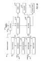
- FIG. 1Ais a block diagram of a robotic medical system including a stereo viewer and an image guided surgery (IGS) system with a tool tracking sub-system.
- IGSimage guided surgery
- FIG. 1Bis a block diagram of a patient side cart including robotic surgical arms to support and move robotic instruments.
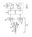
- FIG. 2is a functional block diagram of the video portion of the IGS system to provide a stereo image in both left and right video channels to provide three-dimensional images in a stereo viewer.
- FIG. 3is a perspective view of a robotic surgical master control console including a stereo viewer and an IGS system with tool tracking sub-system.
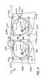
- FIG. 4is a perspective view of the stereo viewer of the robotic surgical master control console.
- FIG. 5Ais a perspective view of a sequence of video frames including video images of a robotic medical tool that may be used to perform tool tracking.
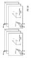
- FIG. 5Billustrates different tool positions of a pair of tools in the field of view of a camera based on kenematic information and video image information.
- FIG. 6Ais a functional block diagram of a tool tracking architecture and methodology for a robotic system including one or more robotic instruments.
- FIG. 6Bis a flow chart of a tool tracking library and its application.
- FIG. 7is a block diagram illustrating various techniques that may be combined together to meet the challenges in tool tracking.
- FIG. 8is a functional flow-chart of a tool tracking system.
- FIG. 9Ais a figure to illustrate the process of pure image segmentation to localize a tool within an image.
- FIG. 9Bis a figure to illustrate the process of sequence matching and/or model-based synthesis to localize a tool within an image.
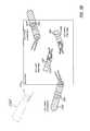
- FIG. 9Cis a more detailed figure to illustrate the process of model-based synthesis to localize a tool within an image.
- FIGS. 10A-10Billustrates elements of a state-space model to adaptively fuse robot kinematics information and vision-based information together.
- FIG. 11A-Cillustrate various image matching techniques that may be used separately or collectively to determine pose information of a tool.
- FIG. 12Ais a diagram illustrating adaptive fusion under different viewing conditions.
- FIG. 12Bis a diagram illustrating a set up for parallel stereo.
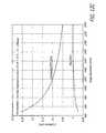
- FIGS. 12C-12Eare charts illustrating various view geometry statistics that may be used to enhance the performance of the state space model for adaptively fusing information sources together.
- FIGS. 13A-13Bare diagrams illustrating sequence matching of a feature in a sequence of one or more images from different sources.
- FIG. 14is a diagram illustrating appearance learning of objects within an image.
- FIG. 15is a flow chart of the application of tool tracking to image guided surgery.
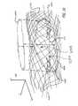
- FIG. 16is a perspective view of overlaying a pre-scanned image of tissue onto a depth map of a surgical site to provide image-guided surgery.
- FIG. 17is a perspective view of a surgical site with an ultrasound tool capturing ultrasound images for overlay onto a display.
- aspects of the inventioninclude methods, apparatus and integrated systems for tool acquisition (locating) and tool tracking (kinematics-tracking (pose predicting) and full-tracking) of robotic medical tools.
- the method/system for tool trackingsystematically and efficiently integrates robot kinematics and visual information to obtain pose (position/orientation) information, which can be used to obtain a more accurate pose of a robotic surgical tool than robot kinematics or visual information alone, in either a camera coordinate system or a base coordinate system.
- poseposition/orientation
- Known kinematics transformationcan be applied to the pose correction to achieve improved pose in any related coordinate system.
- a camera coordinate systemis a coordinate system based on a chosen camera (for example, (X r , Y r , Z r ) in FIG.
- tool trackingexplores prior available information, such as the CAD models of tools, and dynamically learns the image appearances of the robotic instruments.
- tool trackingmay be markerless so as not to interfere with normal robotic surgical procedures.
- tool trackingmay provide continuous pose information of the robotic instruments including their relationships (e.g. tool A is on top of tool B and hence partially occluding tool B) with other tools so that image-based segmentation of the tools may be avoided.
- a block diagram of a robotic surgery system 100is illustrated to perform minimally invasive robotic surgical procedures using one or more robotic arms 158 .
- Aspects of system 100include telerobotic and autonomously operating features. These robotic arms often support a robotic instrument.
- a robotic surgical arme.g., the center robotic surgical arm 158 C
- a stereo or three-dimensional surgical image capture device 101 Csuch as a stereo endoscope (which may be any of a variety of structures such as a stereo laparoscope, arthroscope, hysteroscope, or the like), or, optionally, some other imaging modality (such as ultrasound, fluoroscopy, magnetic resonance imaging, or the like).
- Robotic surgerymay be used to perform a wide variety of surgical procedures, including but not limited to open surgery, neurosurgical procedures (e.g., stereotaxy), endoscopic procedures (e.g., laparoscopy, arthroscopy, thoracoscopy), and the like.
- neurosurgical procedurese.g., stereotaxy
- endoscopic procedurese.g., laparoscopy, arthroscopy, thoracoscopy
- a user or operator O(generally a surgeon) performs a minimally invasive surgical procedure on patient P by manipulating control input devices 160 at a master control console 150 .
- a computer 151 of the console 150directs movement of robotically controlled endoscopic surgical instruments 101 A- 101 C via control lines 159 , effecting movement of the instruments using a robotic patient-side system 152 (also referred to as a patient-side cart).
- the robotic patient-side system 152includes one or more robotic arms 158 .
- the robotic patient-side system 152includes at least three robotic surgical arms 158 A- 158 C (generally referred to as robotic surgical arms 158 ) supported by corresponding positioning set-up arms 156 .
- the central robotic surgical arm 158 Cmay support an endoscopic camera 101 C.
- the robotic surgical arms 158 A and 158 B to the left and right of centermay support robotic instruments 101 A and 101 B, respectively, that may manipulate tissue.
- Robotic instrumentsare generally referred to herein by the reference number 101 .
- Robotic instruments 101may be any instrument or tool that couples to a robotic arm that can be manipulated thereby and can report back kinematics information to the robotic system.
- Robotic instrumentsinclude, but are not limited to, surgical tools, medical tools, bio-medical tools, and diagnostic instruments (ultrasound, computer tomography (CT) scanner, magnetic resonance imager (MRI)).
- CTcomputer tomography
- MRImagnetic resonance imager
- the robotic patient-side system 152includes a positioning portion and a driven portion.
- the positioning portion of the robotic patient-side system 152remains in a fixed configuration during surgery while manipulating tissue.
- the driven portion of the robotic patient-side system 152is actively articulated under the direction of the operator O generating control signals at the surgeon's console 150 during surgery.
- the driven portion of the robotic patient-side system 152may include, but is not limited or restricted to robotic surgical arms 158 A- 158 C.
- the instruments 101 , the robotic surgical arms 158 A- 158 C, and the set up joints 156 , 157may include one or more displacement transducers, positional sensors, and/or orientational sensors 185 , 186 to assist in acquisition and tracking of robotic instruments. From instrument tip to ground (or world coordinate) of the robotic system, the kinematics information generated by the transducers and the sensors in the robotic patient-side system 152 is reported back to the robotic system and a tool tracking and image guided surgery (IGS) system 351 .
- IGStool tracking and image guided surgery
- the positioning portion of the robotic patient-side system 152 that is in a fixed configuration during surgerymay include, but is not limited or restricted to set-up arms 156 .
- Each set-up arm 156may include a plurality of links and a plurality of joints.
- Each set-up armmay mount via a first set-up-joint 157 to the patient side system 152 .
- An assistant Amay assist in pre-positioning of the robotic patient-side system 152 relative to patient P as well as swapping tools or instruments 101 for alternative tool structures, and the like, while viewing the internal surgical site via an external display 154 .
- the external display 154 or another external display 154may be positioned or located elsewhere so that images of the surgical site may be displayed to students or other interested persons during a surgery. Images with additional information may be overlaid onto the images of the surgical site by the robotic surgical system for display on the external display 154 .
- the robotic patient-side system 152comprises a cart column 170 supported by a base 172 .
- One or more robotic surgical arms 158are respectively attached to one or more set-up arms 156 that are a part of the positioning portion of robotic patient-side system 152 .
- the cart column 170includes a protective cover 180 that protects components of a counterbalance subsystem and a braking subsystem (described below) from contaminants.
- each robotic surgical arm 158is used to control robotic instruments 101 A- 101 C. Moreover, each robotic surgical arm 158 is coupled to a set-up arm 156 that is in turn coupled to a carriage housing 190 in one embodiment of the invention, as described below with reference to FIG. 3 . The one or more robotic surgical arms 158 are each supported by their respective set-up arm 156 , as is illustrated in FIG. 1B .
- the robotic surgical arms 158 A- 158 Dmay each include one or more displacement transducers, orientational sensors, and/or positional sensors 185 to generate raw uncorrected kinematics data, kinematics datum, and/or kinematics information to assist in acquisition and tracking of robotic instruments.
- the robotic instrumentsmay also include a displacement transducer, a positional sensor, and/or orientation sensor 186 in some embodiments of the invention.
- one or more robotic instrumentsmay include a marker 189 to assist in acquisition and tracking of robotic instruments.
- the stereo endoscopic camera 101 Cincludes an endoscope 202 for insertion into a patient, a camera head 204 , a left image forming device (e.g., a charge coupled device (CCD)) 206 L, a right image forming device 206 R, a left camera control unit (CCU) 208 L, and a right camera control unit (CCU) 208 R coupled together as shown.
- the stereo endoscopic camera 101 Cgenerates a left video channel 220 L and a right video channel 220 R of frames of images of the surgical site coupled to a stereo display device 164 through a video board 218 .
- a lock reference signalis coupled between the left and right camera control units 208 L, 208 R.
- the right camera control unitgenerates the lock signal that is coupled to the left camera control unit to synchronize the left view channel to the right video channel.
- the left camera control unit 208 Lmay also generates the lock reference signal so that the right video channel synchronizes to the left video channel.
- the stereo display 164includes a left monitor 230 L and a right monitor 230 R.
- the viewfinders or monitors 230 L, 230 Rmay be provided by a left display device 402 L and a right display device 402 R, respectively.
- the stereo imagesmay be provided in color by a pair of color display devices 402 L, 402 R.
- Stereo images of a surgical sitemay be captured by other types of endoscopic devices and cameras with different structures. For example, a single optical channel may be used with a pair of spatially offset sensors to capture stereo images of the surgical site.
- the master control console 150 of the robotic surgical system 100may include the computer 151 , a binocular or stereo viewer 312 , an arm support 314 , a pair of control input wrists and control input arms in a workspace 316 , foot pedals 318 (including foot pedals 318 A- 318 B), and a viewing sensor 320 .
- the master control console 150may further include a tool tracking and image guided surgery system 351 coupled to the computer 151 for providing the tool images and tissue images overlaid on the visible surgical site images.
- the tool tracking and image guided surgery system 351may be located elsewhere in the robotic surgical system 100 , such as the patient side cart 152 or a separate computer system.
- the stereo viewer 312has two displays where stereo three-dimensional images of the surgical site may be viewed to perform minimally invasive surgery.
- the operator Otypically sits in a chair, moves his or her head into alignment with the stereo viewer 312 to view the three-dimensional annotated images of the surgical site.
- the master control console 150may include the viewing sensor 320 disposed adjacent the binocular display 312 .
- the system operatoraligns his or her eyes with the binocular eye pieces of the display 312 to view a stereoscopic image of the surgical worksite, the operator's head sets off the viewing sensor 320 to enable the control of the robotic instruments 101 .
- the viewing sensor 320can disable or stop generating new control signals in response to movements of the touch sensitive handles in order to hold the state of the robotic instruments.
- the processing required for tool tracking and image guided surgerymay be entirely performed using computer 151 given a sufficiently capable computing platform.
- the arm support 314can be used to rest the elbows or forearms of the operator O (typically a surgeon) while gripping touch sensitive handles of the control input wrists, one in each hand, in the workspace 316 to generate control signals.
- the touch sensitive handlesare positioned in the workspace 316 disposed beyond the arm support 314 and below the viewer 312 . This allows the touch sensitive handles to be moved easily in the control space 316 in both position and orientation to generate control signals.
- the operator Ocan use his feet to control the foot-pedals 318 to change the configuration of the surgical system and generate additional control signals to control the robotic instruments 101 as well as the endoscopic camera.
- the computer 151may include one or more microprocessors 302 to execute instructions and a storage device 304 to store software with executable instructions that may be used to generate control signals to control the robotic surgical system 100 .
- the computer 151 with its microprocessors 302interprets movements and actuation of the touch sensitive handles (and other inputs from the operator O or other personnel) to generate control signals to control the robotic surgical instruments 101 in the surgical worksite.
- the computer 151 and the stereo viewer 312map the surgical worksite into the controller workspace 316 so it feels and appears to the operator that the touch sensitive handles are working over the surgical worksite.
- the computer 151may couple to the tool tracking and image guided surgery system 351 to execute software and perform computations for the elements of the image guided surgery unit.
- the tool tracking system described hereinmay be considered as operating in an open-loop fashion if the surgeon operating the master console is not considered part of the system. If the robotic instrument is to be automatically controlled with the tool tracking system, such as in visual servoing systems used to control the pose of a robot's end-effector using visual information extracted from images, the tool tracking system may be considered to be operating in a closed visual-feedback loop.
- the viewer 312includes stereo images for each eye including a left image 400 L and a right image 400 R of the surgical site including any robotic instruments 400 respectively in a left viewfinder 401 L and a right viewfinder 401 R.
- the images 400 L and 400 R in the viewfindersmay be provided by a left display device 402 L and a right display device 402 R, respectively.
- the display devices 402 L, 402 Rmay optionally be pairs of cathode ray tube (CRT) monitors, liquid crystal displays (LCDs), or other type of image display devices (e.g., plasma, digital light projection, etc.).
- the imagesare provided in color by a pair of color display devices 402 L, 402 R; such as color CRTs or color LCDs.
- three dimensional maps(a depth map with respect to a camera coordinate system or equivalently a surface map of an object with respect to its local coordinate system is a plurality of three-dimensional points to illustrate a surface in three dimensions) of the anatomy, derived from alternative imaging modalities (e.g. CT scan, XRAY, or MRI), may also be provided to a surgeon by overlaying them onto the video images of the surgical site.
- alternative imaging modalitiese.g. CT scan, XRAY, or MRI
- a right image 410 R rendered from a three dimensional map such as from a CT scanmay be merged onto or overlaid on the right image 400 R being displayed by the display device 402 R.
- a rendered left image 410 Lis merged into or overlaid on the left image 400 L of the surgical site provided by the display device 402 L.
- a stereo imagemay be displayed to map out organ location or tissue location information in the surgical site to the operator O in the control of the robotic instruments in the surgical site, augmenting the operator's view of the surgical site with information that may not be directly available or visible by an endoscopic camera in the surgical site.
- a stereo video endoscopic camera 101 Chas been shown and described, a mono video endoscopic camera generating a single video channel of frames of images of the surgical site may also be used in a number of embodiments of the invention. Rendered images can also be overlaid onto the frames of images of the single video channel.
- Tool trackinghas a number of applications in robotic surgical systems.
- One illustrative application of tool trackingis to automatically control the motion of the endoscopic camera so that a surgeon automatically views regions of interest in a surgical site, thus freeing the surgeon from the camera control task.
- robotic instrumentsare tracked so that the endoscopic camera is centered in the field of view of the surgical site.
- Another illustrative application for accurate tool trackingmay be used to move a robotic instrument to reach a surgical target (e.g., a tumor) either automatically or by a surgeon.
- a surgical targete.g., a tumor
- other real-time imaging modalitiessuch as ultra-sound or pre-scanned images, may be used with real-time tool tracking to move a robotic instrument to the tumor and remove it.
- GUIgraphic user interface
- a tool tracking system and architecturethat fully integrates kinematics information and visual information for robust and accurate tool tracking performance. Results of tool localization and tracking are made accurate and reliable by adaptively combining together robust kinematics information and accurate geometric information derived from video.
- the tool tracking systemperforms locating (determining absolute locations/poses with stereo video), tracking (integrating visual and kinematics) and predicting (kinematics while the tool or a portion thereof is not visible) functions.
- An analysis-by-synthesis capabilitymakes it possible to explore the prior information that is of concern, such as information about the tools and not the tissue and surrounding environment.
- the basic procedure in analysis-by-synthesisis to synthesize an image based on the model (geometry and texture) and the current pose (position/location and orientation) of a tool and then compare it against real images.
- the error between the real and synthesized imagesis the driving force for better estimation of tool pose.
- appearance-based learningmay be applied to update the model for a specific tool.
- matchingmay be performed using features, such as edges and/or corners, that are more robust to lighting variation.
- stereo imagingmay be used along with the analysis-by-synthesis (ABS) techniques.
- ABSanalysis-by-synthesis
- a stereo approachmay be provided based on the tool (or some of its parts).
- stereo and ABS techniquesmay be applied to a sequence of images (e.g., the same location and different orientations or different locations and different orientation). Sequence-based matching makes the procedure less vulnerable to local minimum in the process of optimization/estimation.
- a sequential Bayesian approachmay be applied to fuse visual information and robot kinematics to efficiently track tools.
- the statesprovide zero-order kinematics of the tools (e.g. current position and orientation, or pose), and the first-order kinematics of the tools (e.g. translational and angular velocity).
- higher-order or lower-order state space modelmay be adopted.
- a linear Kalman filteringmay be applied when the noise can be approximated as Gaussian.
- an extended Kalman filteringmay be used to filter out noise from observations and state dynamics.
- sequential Monte Carlo methode.g., particle filtering
- the point distribution functionmay be represented by a set of representative samples.
- the sourcesshould be correctly characterized, for example, in terms of observation noise characteristics.
- observation noisese.g., pixel location of a feature point
- observatione.g., pixel location of a feature point
- a robotic instrumentthat is under a slanted viewing angle or is occluded by other tools has a large variance.
- tool trackinginvolves determining a pose of a robotic instrument 101 including its position or location (Xt,Yt,Zt) and its orientation in the camera coordinate system as it moves in, around, and out of the surgical site.
- a full pose descriptionmay not only include the location and orientation of a robotic instrument in a three dimensional space but may further include the pose of an end-effector, if any.
- Positional information or pose as used hereinmay be used to refer to one or both the location and orientation of a robotic instrument.
- a sequence of left video frames 500 L within a camera coordinate system and a sequence of right video frames 500 R within another camera coordinate systemmay be used for tool tracking in one embodiment of the invention.
- a single view with a single sequence of video framesmay be used for tool tracking in another embodiment of the invention.
- a single video framemay be used for tool tracking in yet another embodiment of the invention providing partially corrected pose estimates.
- a marker 502 on the robotic instrument 101may be used to assist in the tool tracking if visible or otherwise sensible.
- the marker 502is a painted marker minimally altering the robotic instruments.
- markerless tool trackingis provided with no modification of the robotic instruments.
- natural image features of a robotic toolmay be detected as natural markers and/or image appearance of the tools and the CAD model of tools may be used to provide tool tracking.
- video information from an endoscopic camera and kinematics of the robotic arm and robotic instrumentare used as cues to determine the pose of the robotic instrument in the surgical site. If the robotic instrument is not visible to the camera, the video information alone is insufficient to determine position but the kinematics adds the missing information to determine robotic instrument pose. Moreover, even if the video information is available, the addition of the kinematics information makes the computation of pose more robust.
- a tool tracking systemis provided based on robot kinematics and vision that requires little to no modifications to the robotic instruments 101 and the pre-existing surgical system 100 .
- Kinematics information provided by the surgical system 100may include kinematic position k t P , kinematic orientation k t ⁇ , kinematic linear velocity ⁇ dot over (k) ⁇ t P , and kinematic angular velocity ⁇ dot over (k) ⁇ t ⁇ of one or more robotic instruments 101 .
- the kinematics informationmay be the result of movement of the robotic surgical arm 158 , the robotic instrument 101 , or both the robotic surgical arm 158 and robotic instrument 101 at a given time.
- the kinematics information provided by the surgical system 100may also include the kinematic position k t P , kinematic orientation k t ⁇ , kinematic linear velocity ⁇ dot over (k) ⁇ t P , and kinematic angular velocity ⁇ dot over (k) ⁇ t ⁇ of the endoscopic camera to provide a frame of reference.
- FIG. 6Aa functional block diagram of a tool tracking architecture and methodology for a surgical system is illustrated in accordance with embodiments of the invention.
- the main operational stages of tool trackingare illustrated in the middle column of FIG. 6A .
- Key technical capabilities associated with tool trackingare illustrated in the left column of FIG. 6A but for operational constraints 601 .
- the end results of the tool tracking methodologyare illustrated in the right column of FIG. 6A .
- the key technical components of the methodology and architecturemay be further categorized into basic building blocks and supporting blocks.
- the basic building blocksincluding image matching 609 and a state-space model 613 that are used to provide efficient tool tracking, each of which are responsive to visual information.
- the supporting blocksinclude model-based synthesis 611 , adaptive fusion 615 , and sequence matching 607 to support the implementation of robust and accurate tool tracking.
- Adaptive fusion 615fully explores prior information that may be available, including prior kinematics information and prior visual information.
- vision information and kinematics informationare typically available with known characteristics.
- Robot kinematics informationis usually stable and often accurate but may drift during long periods of time.
- Vision-based informationis very accurate when it can be reliably estimated. Otherwise vision-based information may be very inaccurate.
- adaptive fusionis used to obtain accurate information fusion from different sources of information as well as similar sources of information.
- the vision-based informationis known to be accurate then the information fusion is heavily biased towards the vision-based information.
- robot kinematics informationis used over the vision-based information to generate a more robust fusion of information. While the quality of robot kinematics is typically uniform, the quality of vision information in terms of image matching and 3D post estimation varies a lot. View geometry statistics may be used to determine the reliability and accuracy of video-based information.
- Adaptive fusionmay also be used to obtain accurate information fusion from similar sources of information.
- Model-based synthesisis used herein to generally refer to generation or rendering of a template image for use in subsequent matching operations, and includes full synthesis, geometry only synthesis, and implicit synthesis.
- Full synthesisis a complete synthesis of an image of the robotic instrument.
- robotic instrument imagesare generated from a computer aided design (CAD) model based on its geometry and texture.
- CADcomputer aided design
- Other prior information(the location/orientation of the model), not necessarily accurate, is presented along with the synthesized robotic instrument images for image matching 609 .
- Geometry-only synthesisis the case where the geometry of the robotic instrument is used to synthesize geometry-only images (e.g., edge images). Texture of the model is not used in geometry-only synthesis.
- Implicit synthesisis the case where images are not actually synthesized. Instead the model (either geometry or texture or both) is implicitly used to perform image matching.
- the geometric propertiese.g., width, length, shape
- the geometric relationship among theme.g., markers forming a line
- sequence matchingis where objects or features in a sequence of images captured from one camera view are matched against objects or features in a sequence of images captured from a different camera view. In another embodiment of the invention, sequence matching is where objects or features in a sequence of images from a camera view are matched against objects or features in a sequence of synthesized images.
- Tool acquisitionmay also be referred to as localization herein.
- the goal of the tool acquisition stage 604is to obtain the absolute pose information (location and orientation) of the one or more robotic instruments within the field of view of one or more cameras, such as the stereo endoscopic camera 101 C.
- the tool acquisition stage 604performs a locating function 614 resulting in the location and orientation of the tool.
- the goal of the tool tracking stage 606is to dynamically update the absolute pose (location and orientation) of a moving robotic instrument.
- the tool tracking stage 606may perform a full-tracking function 616 or a kinematics-tracking (pose prediction) function 618 respectively resulting in either a full-tracking state when both visual information and robot kinematics information are available or a kinematics-tracking state when visual information is not utilized (e.g., tool outside the field of view or occluded).
- the mode/stage of the tool tracking systemchanges from tool acquisition to tool tracking after the tool is initially located within the field of view.
- the tool tracking systemmay remain in the tool tracking mode/stage.
- the tool tracking systemmay change from a tool tracking mode/stage into a tool acquisition mode/stage if the tool is removed from the field of view and then returns into the field of view.
- the tool tracking systemmay optionally begin operation with an initialization procedure if there is only a single tool in the field of view. If additional tools are to be tracked, the optional initialization procedure may be skipped as other tools have been located and tracked. If the tools have no markers, the optional initialization procedure may involve tools moving around in order to obtain a robust localization via sequence matching.
- FIG. 6Astarts at block 600 and goes to block 602 .
- an optional initialization of the tool tracking systemmay occur.
- Mono or stereo video 603may be used in the tool tracking system and is initialized to begin generation of digital video frames of image data of the surgical site.
- Kinematics information 605may also be used in the tool tracking system during initialization to form an initial pose of the robotic instrument.
- the kinematics information 605may include positional information, including angular or linear information for example, from sensors located at various places along a robotic arm and the robotic instrument.
- the kinematics information 605may be for both the endoscopic camera and robotic instruments such that the relationship between positional information for the robotic instruments and the camera may be determined.
- Initializationbegins with a single tool in the field of view without any occlusions.
- the systemmay be initialized for additional robotic instruments in the field of view. If tools have already been located and tracked and a new tool is being added, the new tool can be initialized by placing it into the field of view with the previously located and tracked tools. If no tool has been located and tracked, each tool may be initialized by placing it within the field of view with all other tools outside the field of view.
- the robotic instrument being initializedmay be placed in the center of the surgical site for optimal estimation across the whole space or as close to stereo endoscopic camera 101 C as possible that will allow for accurate stereo computation. With a markerless system, the robotic instrument may be moved and rotated for reliable sequence matching.
- FIG. 9Bgraphically illustrates the tool acquisition stage in a surgical site.
- Stereo video images 500 L, 500 R of the surgical siteare captured by the endoscopic camera 101 C, including one or more robotic instruments 101 in the surgical site.
- Stereo videomay be used to obtain an absolute initial pose of the one or more robotic instruments 101 in one embodiment of the invention.
- mono videomay be used with kinematics information to estimate absolute initial pose (position and orientation) of the one or more robotic instruments 101 .
- the one or more robotic instruments 101may include painted markers 502 to assist in tool acquisition and tool tracking in the surgical site.
- the tool acquisition stageperforms a locating function 614 resulting in the initial pose of the one or more robotic instruments 101 in the surgical site.
- the methodologygoes to block 606 .
- the tool tracking systementers a tool tracking mode or stage in the surgical site.
- the goal of tool trackingis to update the absolute pose information (location and orientation) based on incremental and/or partial information (visual and robot kinematics).
- the tool tracking systemis at a full-tracking state 616 when visual and kinematics information is available. If a robotic instrument is not visible (e.g., tools inside an organ or occluded by other tools) in the surgical site, the tool tracking system is at a kinematics-tracking state 618 for estimating tool pose.
- the tool tracking systemmay transition from tool tracking 606 and return to tool acquisition 604 if a tracked tool gets out of field of view and then comes back into the field of view of the camera.
- a tool tracking application 650is executed by a system 351 of the robotic surgical system 100 .
- the video board 218 illustrated in FIG. 2may be a part of the IGS system 351 in order to receive the video images from the endoscopic camera over the surgical site.
- a kinematics application programming interface (API) 660provides a software interface to receive the raw kinematics data from the surgical system 100 .
- the kinematics API 660couples the kinematics information to the tool tracking application 650 and a tool tracking library 652 .
- the raw kinematics data 680is received by an API streamer thread 658 which provides the physical interface to a communication channel (for example, fiber optic cable or Ethernet, and may buffer the raw kinematics data by storing it into a memory, a hard disk, or other data storage device).
- the tool tracking library 652may issue data requests to the API streamer thread 658 .
- a video capture thread 656is coupled to the endoscopic camera to receive the raw endoscopic video feed 670 .
- the raw video 670may be mono video of a single channel or stereo video of left and right channels.
- the video capture thread 656may buffer the raw video data by storing it into a frame buffer memory, a hard disk, or other data storage device.
- a video application programming interface (API) 659provides the software interface to receive the raw video data from the surgical system into the tool tracking system.
- the tool tracking library 652may issue data requests to the video capture thread 656 .
- the tool tracking library 652contains the core functionality of combining kinematics (through kinematics API 660 ) and video (through video API 659 ) for accurate tracking of tools.
- the libraryalso provides application program interface so it can be invoked in a certain way by a customer-designed tool tracking application 650
- the tool tracking library 652In response to the video data and the kinematics data, the tool tracking library 652 generates corrected kinematics data for the pose of a robotic instrument.
- the raw kinematics datais corrected for orientation and position of the tools.
- the corrected kinematics datamay be used in a number of applications, such as image guided surgery.
- the speed of raw kinematics 680may be 100 to 200 Hertz (Hz) and the speed of raw video 670 may be 30 Hz to 60 hz and the speed of tool tracking maybe even slower.
- the speed of the corrected kinematics 690should be substantially similar to the speed of the raw kinematics 680 for medical applications.
- the raw kinematicsmay be passed through.
- a correction matrix(rotation and translation) may then be used to correct the raw kinematics information from the tool tracking library.
- the corrected kinematics 690may be directly output from the tool tracking library 652 where a correction matrix is applied to the raw kinematics. Either way is feasible because the correction matrix corrects the bias in the raw kinematics and the bias changes slowly, for example, slower than 1 Hz.
- FIG. 6Aillustrated previously, illustrates a functional block diagram including operational stages of a tool tracking system.
- FIG. 7is a block diagram illustrating the challenges of performing tool tracking.
- FIG. 8graphically illustrates a functional block diagram of a tool tracking system 800 .
- the tool tracking system 800adaptively fuses visual information and robot kinematics in order to achieve robust, accurate and efficient tool tracking.
- the unknown full pose of a robotic instrument, at a time instant t,is represented as a state s t 805 B in a Bayesian state-space model 802 .
- the state-space model 802may use a plurality of posed states 805 A- 805 C to perform tool tracking in the surgical site.
- the state-space model 802may generate the corrected kinematics information 690 of the robotic instrument.
- a CAD tool model 804(geometry only or both geometry and texture) is used for synthesizing (explicitly or implicitly) an image under a given pose (i.e. state).
- the relative robot kinematics ⁇ dot over (k) ⁇ t 605(where the dot above the k being used to represent that the relative or first-derivative measurements of the kinematics information) between time instances t to t+1 can be coupled into the state-space model 802 .
- Visual information 603 from captured imagesmay be amplified and analyzed by an amplifier/filter 808 to control the influence of visual feedback 809 on the fusion of visual information and kinematics information.
- the amplifier/filter 808generally implements how view geometry statistics are applied for adaptive fusion. If stereo images 803 are available, the spatial constraints 807 between left and right image pairs may also be explicitly or implicitly explored to assist in tool tracking.
- the natural challengesare those imposed by realistic operational scenarios.
- the technical challengesare those caused by proposed tool tracking algorithms when facing natural challenges.
- the natural challengesfor example include cluttering and occlusion 702 , illumination variation and image appearance change 703 , and viewing singularity 704 .
- the technical challengesinclude image segmentation 710 and matching ambiguity 712 , for example.
- the natural challenge of illumination and image appearance 703is where the same scene changes dramatically along with the motion of directional light sources.
- the image intensity of the same objectcan be different, depending on the distance of the object from the lighting source and the angle between the lighting source and local surface normal. This makes image-based processing less reliable.
- specularities from organs, blood that under directional endo-illuminationmake image processing more challenging.
- the natural challenge of viewing singularity 704may occur when three dimensional geometry information is derived from two dimensional images.
- Three dimensional geometry information derived from two dimensional imagesis not reliable when the two dimensional projection of a three dimensional object is degenerated. For example, a three dimensional cylindrical tool is projected onto an image plane as a circle.
- the natural challenge of scene cluttering and occlusion 702is the case where there could be more than one robotic instrument in the field of view. Additionally, the robotic instruments may be partially or fully submerged with complex and dynamic background of organ tissues, blood and smoke caused by electro-dissection.
- the technical challengesinclude image segmentation 710 and matching ambiguity 712 .
- a big technical challenge for tool trackingmay be reliability and accuracy under realistic situations.
- model based synthesis techniques 722may be used.
- model based synthesis 722a CAD model of a robotic instrument may be used to render a clean tool image as a pattern to match against or search within a limited region constrained by the pose information of tool. As a result, pure image segmentation from the real images is avoided. Because the states of all robotic instruments are tracked, mutual occlusions of all these robotic instruments can be calculated thereby making image matching more reliable.
- many areas in an image look alike and non-corresponding areas of two imagesmay appear to be more alike than two corresponding areas (for example, due to illumination variations), making region-based matching ambiguous.
- sequence matching 728may be applied where a sequence of images will be matched against another sequence of images. Such a method is useful when we use robust and accurate relative kinematics information ⁇ dot over (k) ⁇ t .
- sequence matching 728can provide a more robust and more reliable matching as the number of unknowns is reduced and the same number of observations (real images) are kept.
- appearance learning techniques 724may be used to handle image or appearance changes 703 such as from illumination variations and natural wear of a tool, for example.
- appearance learning techniqueshandle appearance changes by training the tool tracking system on image samples of the same tool under different viewing conditions.
- Appearance learning techniqueshave been used extensively in object tracking to handle appearance change due to illumination variations. For example, parametric models have been built to handle illumination variations. Appearance learning techniques are further illustrated herein with reference to FIG. 14 with the use of face images instead of tool images.
- adaptive fusion techniques 726may be used to handle the challenges of singularity of viewing geometry or viewing singularity 704 .
- the technique of adaptive fusionis used to explore the available pose information, i.e., predicted state (before correction) when feeding geometric information derived from video into the Bayesian state-space model 802 . More specifically, video-derived information has much less weight when fused with robot kinematics information under such conditions. In a Bayesian state-space model 802 , this manifests itself as large noise variance in the observation equation.
- Adaptive fusionmay be used to handle the challenges of singularity of viewing geometry in order to provide robust and accurate kinematics information of the tools in a surgical, medical, or other type of robotic system.
- Pure image segmentationmay be used by a tool tracking algorithm to localize tools. Pure image segmentation of tools from a two dimensional image is straightforward if the tools have distinctive features, such as color marks that may be used to identify a tool. However, operational conditions may make pure image segmentation techniques difficult if not impossible to perform.
- an imagehas a tool 901 hidden by an occlusion 902 .
- the occlusion 902is so severe that it breaks key steps (e.g., color- and/or shape-based analysis) of pure image segmentation of the image such that the tool 901 cannot be found therein.
- the tool shape 901 Sis substantially covered over by the occlusion shape 902 S in the image illustrated in FIG. 9A .
- an occlusioncan only make it more difficult for pure image segmentation techniques to localize a tool.
- the image of the tool 901is again hidden by an occlusion 902 .
- Techniques of sequence matching and/or model-based-synthesis matchingmay be used to localize the robotic instruments instead of pure image segmentation. Sequence matching was briefly discussed previously. Model based synthesis uses a priori knowledge regarding kinematics and appearance that may be available for the tools that are being tracked.
- a CAD model 904 A of the tool 901is used to synthesize an image of the tool given the known or hypothesized pose information for the tool.
- the pose information for the toolmay be determined from kinematics information or otherwise and a posed synthesized image 904 B may then be generated.
- the posed synthesized image 904 B of the tool 901may then be used to perform image matching or an image search within the overall image of a surgical site to find the location of the tool 901 therein even though it may be partially occluded.
- This technique of tool localizationmay generally be referred to herein as an analysis-by-synthesis approach.
- image segmentationmay be guided by exploring the available prior kinematics and image information. That is, image segmentation may be constrained to be performed within a limited region of the image of the surgical site based on rough pose information of the tool in response to the prior robot kinematics and the CAD model 904 A of the tool 901 .
- This technique of tool localizationmay generally be referred to herein as aided image segmentation in contrast to pure image segmentation that has no constraints.
- image synthesisalso referred to herein as model-based synthesis
- image analysis/searchare key steps in using analysis-by-synthesis methods for tool localization and tool tracking.
- the image synthesis 911 and image analysis/search 915 processesmay be repeatedly performed in an iterative optimization approach to find the best tool pose parameter in response to a given cost function CF 913 .
- an initial pose hypothesismay be formulated to generate the initial synthesized model tool for computation of an initial cost function.
- the cost function CF 913is a function of what corresponding features 912 , 914 are used for matching and how an image is synthesized during image synthesis 911 .
- a synthesize edge image 904 S of the toolmay be synthesized during image synthesis 911 in response to the CAD geometry of the CAD model 904 A of the tool.
- a synthesized regular image 904 B of the toolmay be synthesized during image synthesis 911 in response to the CAD geometry and CAD texture of the CAD model 904 A of the tool.
- the synthesize edge image 904 S of the toolmay be used to perform image matching with edges in a video image 910 A of the tool.
- the synthesized regular image 904 B of the toolmay be used to perform image matching with a regular video image 910 B of the tool.
- appearance learningmay be used to augment the analysis-by-synthesis process for tool localization and tool tracking.
- an edge imagesuch as illustrate in video image 910 A, is typically robust against lighting variations.
- the model texture ⁇ tcan be mapped to the coordinate of image I s [x] as a function of the homogeneous camera geometric projection ⁇ and a combination of tool pose (position P and orientation ⁇ of the tool), and the geometry ⁇ g of the tool model.
- the modelwill be decomposed into triangles, the 3D vertex coordinates of which will be described in a coordinate system attached to the model.
- the model coordinateswill first be transformed to a world coordinate system, before being projected to a 2D display coordinate system by applying the camera model. Once in the 2D display coordinate system, each triangle will be rasterized.
- the synthesis of the final per-pixel color valuesmay be computed via interpolation of color specified on a per-vertex basis, texture mapping and filtering, and the application of lighting models. (Reference: Computer Graphics: Principals and Practice, by James D. Foley, Andries van Dam, et. al, Addison-Wesley Professional; 2 edition, Aug. 4, 1995, ISBN: 978-0201848403).
- the function Lis a mapping function that maps the model texture ⁇ t into the real image/appearance I s [x] because the real image varies with lighting conditions and other factors, such as occlusions.
- Camera coordinates of a 3D point 931 P on the tool that maps to xmay be represented by [X,Y,Z] T .
- a local coordinate of the 3D point 931 P on the tool that is internal to the tool modelmay be represented as [X M ,Y M ,Z M ] T .
- T ⁇ P , ⁇ ⁇ *arg ⁇ ⁇ min T ⁇ P , ⁇ ⁇ ⁇ C ⁇ ( I s , I ) , ( Eq . ⁇ 3 )
- Cis a cost function of comparing images.
- the synthesized tool image I smay be repeatedly generated in an iterative manner using updated pose information so that the cost function C of comparing the synthesized tool image I s with the video images of the surgical site are minimized and the tool pose is optimized.
- SSDsum of squared differences
- an SSDis a simple cost function, it is nonlinear (e.g., higher than quadratic) in terms of the pose parameters due to the camera geometric projection ⁇ that is nonlinear and the mapping function L to map model texture to real image/appearance that varies with lighting conditions that may be non-linear.
- Minimizing a nonlinear cost function Cis a complex optimization problem.
- Different strategiescan be applied to solve a problem of minimizing a nonlinear cost function C.
- random optimization methodsmay be used to solve and minimize a nonlinear cost function C problem in order to avoid an exhaustive parameter search.
- a quadratic approximation of the cost functionmay be use to iteratively solve the nonlinear problem.
- the complex optimization problemmay be broken up into two different steps to more efficiently minimize the cost function C.
- the first stepentails performing an image matching where the raw image pixels or extracted image features of I are used for matching against those of the respective synthesized tool image I s .
- the second stepinvolves performing a geometry-only optimization in response to the result of the image matching between the raw image pixels or extracted image features and corresponding ones from the respective synthesized tool image I s .
- these two steps to solve the optimization problem of Eq. 3may be formulated into the following two equations:
- T ⁇ P , ⁇ ⁇ *arg ⁇ ⁇ min T ⁇ P , ⁇ ⁇ ⁇ ⁇ ( x m - f ⁇ ( X m ) ) 2 . ( Eq . ⁇ 5 )
- Eq.4represent the step of finding the corresponding 2D feature points x m from 1 and 3D points X m on the tool via image matching of I s and I.
- Eq. 5represents the geometry-only optimization where optimal 3D-2D mapping T ⁇ P, ⁇ can be found given the matched 2D-3D pairs.
- the function f( )is a nonlinear function in the following form ⁇ ( ⁇ T ⁇ P, ⁇ ).
- the image matching and analysis-by-synthesis processesmay be incorporated into a sequential framework for fusion of vision and kinematics information to obtain more accurate positional information of a tool than would otherwise be available from each alone.
- appearance learning techniquesmay be used to handle image and appearance changes, such as from illumination variations and natural wear of a tool, for example.
- the appearance variations due to changes in illuminationmay exhibit illumination subspace/cone phenomena or spherical harmonics for example.
- Appearance learning techniquesgenerally train the tool tracking system on image samples of the same tool under different viewing conditions. Pose specific learning techniques may be used as well as clustering or manifold learning techniques may be used to train the tool tracking system over a large number of samples.
- basis images for illumination variations 1401 A, 1401 B, 1401 Cmay be used to train the tool tracking system to generate one or more synthesized images 1402 A- 1402 B which are more closely matched to the respective real images 1045 A- 1405 B that may be captured under different lighting conditions.
- Appearance learning techniqueshave been used extensively in object tracking to handle appearance change due to illumination variations (reference: G. Hager and P. Belhumeur, “Efficient Region Tracking with Parametric Models of Geometry and Illumination,” IEEE Trans. Pattern Analysis and Machine Intelligence, Vol. 20, pp. 1025-1039, 1998).
- parametric modelshave been built to handle illumination variations (reference: H. Murase, S. Nayar, “Learning and Recognition of 3-D Objects from Brightness Images,” Proc. AAAI Fall Symposium, Machine Learning in Computer Vision, pp. 25-29, 1993.
- the next step to obtain more accurate positional informationis the fusion of image positional information and kinematics positional information of the robotic instruments.
- the purpose of information fusionis to provide more robust and/or more accurate positional information for the robotic instruments in the surgical site such that tool tracking information may be applied in various ways to obtain accurate results, e.g., measurements of certain physical entities within a surgical site.
- Key to successfully fusing information together from similar sources or from different sourcesis determining how to adjust the contributions of each to the fusion. The contribution of sources to the information fusion may be adjusted in different ways, such as by a winner-take-all or a weighted averaging method, for example.
- Both raw robotic kinematics information 1010 of the robotic instrument and vision-based information 1101can be used to generate the state variables 1000 A- 1000 D.
- a tool model 804may be used to synthesize 611 the synthesized images 810 in response to the state variables 1000 A- 1000 D.
- An image analysis 806 , 609is performed comparing the synthesized images 810 of the robotic instrument with the observed images 1101 .
- Some real-world data analysis tasksinvolve estimating unknown quantities from given observations. Moreover, a priori knowledge about phenomenon of a number of applications may be available to allow us to formulate Bayesian models involving probability and statistics.
- the unknown quantities of information fusion at corresponding time instancescan be defined as state variables 1000 A- 1000 D (of the system) and a Markov chain model can be assumed among states at different time instances, then a state-space model may be formed.
- the state-space modelmay include 1) a dynamic/state model that relates state variables 1000 A- 1000 D at different time instances (t ⁇ 1, t, t+1, t+2) and 2) an observation model that relates state variables S 1000 A- 1000 D to observations O 1002 A- 1002 D.
- the state-space model(a discrete version is shown—a continuous version is similar and involves temporal integration) may be described by the following set of mathematical equations,
- State-space modelshave been used in many disciplines of science and engineering, and may be referred to by different names such as Bayesian filtering, optimal filtering, stochastic filtering, on-line inference, for example.
- the state-space modelis linear and the modeling noises of the system are Gaussian, then a substantially exact analytic expression can be derived to solve the on-line estimation problem for the state variables of information fusion.
- the analytic expressionthat is well-known and widely used is a Kalman filter (see R. E. Kalman, “A New Approach to Linear Filtering and Prediction Problems,” Trans of the ASM—Journal of Basic engineering, Vol. 82, pp. 35-45, 1960.).
- EKFExtended Kalman Filtering
- SMCSequential Monte Carlo
- srepresents a state vector of the states 1000 A- 1000 D.
- smay be a vector version of the matrix T ⁇ P, ⁇ (Eq. 1), or a collection of point positions [X, Y, Z] T , etc., that are equivalent in theory but may be chosen based on a particular application.
- Respective velocity informationmay be readily added to the state space model by taking the first derivative of the positional information.
- Position and velocitymay be represented mathematically as
- the orientation and angular velocity of the robotic instrumentmay be represented mathematically using unit quaternion for its minimal-style representation and operation efficiency as
- the state vectormay be represented mathematically in a covariance matrix as follows:
- the filter state-space modelmay be implemented with extended Kalman filtering (simple to implement but maybe not sufficient), unscented Kalman filtering (see S. J. Julier and J. K. Uhlmann. A New Extension of the Kalman Filter to Nonlinear Systems. In Proc. of AeroSense: The 11 th Int. Symp. on Aerospace/Defense Sensing, Simulation and Controls., 1997 (easy to implement and maybe sufficient)), or computationally expensive particle filtering.
- Extended Kalman filtering or particle filteringmay be used for tool tracking because 1) the dynamic state space model is non-linear due to the quaternion representation, and 2) the observation model is non-linear in the case of using 2D images as observations and linear in the case of using stereo-derived 3D points as observations.
- Sets of observationsare available to the state space model including robot kinematics (k t P and k t ⁇ ) 1010 and vision 1011 .
- image measurements, the 2D locations of featured points x iare directly used to construct the observation vector O.
- Such a choicemake the observation equation for the vision part nonlinear due to the perspective projection of a 3D tool onto one 2D image in the case of monocular view, or left and right images in the case of stereo view.
- observation matrix C oconsists of two parts: one for kinematics (the leading diagonal sub-matrix of Eq. 12) and one sub-matrix, a covariance matrix C o,v , for vision as follows:
- observation equationis linear for the vision part and we can construct the observation covariance matrix C o,v .
- observation covariance matrix C o,vwe have the following covariance matrix for the case of parallel camera setup ( FIG. 12B ):
- C o , v[ C o , v , 1 C o , v , 2 ... C o , v , n ] ( Eq . ⁇ 13 )
- the view-geometry variance matrices C o,v,iare related to 1) the uncertainty (standard deviation) of matching stereo images, 2) the inverse of image resolution (for example, high-definition camera offers better accuracy than standard-definition camera), and 3) the square of the true values of X s,i .
- first-order kinematic information(velocity information) ( ⁇ dot over (k) ⁇ t P and ⁇ dot over (k) ⁇ t ⁇ ) is provided that may provide an extra constraint with respect to the evolution (e.g., changes from state to state) of the dynamic system.
- first-order vision observationsmay be derived by tracking image points (i.e., temporal image matching) to provide an extra constraint.
- estimated statese.g., tool poses
- observation vectorsmay be formed for the vision-based information and the observation equation is non-linear due to the perspective projection of 3D points to 2D points.
- Kalman filteringprovides a perfect sequential solution to a batch least square optimization problem. Because of the Markovian assumption that given the present state future states are conditionally independent of the past states.
- tool tracking in realityis a nonlinear problem and it is often not easy to achieve an accurate solution with a sequential approach such as extended Kalman filtering.
- an iterative bundle adjustment processthat combines all observations across multiple states may be used starting from initial results provided by the extended Kalman filtering 802 .
- bundle adjustmenthas wide applications.
- bundle adjustmentcan be used for sequential matching to be discussed later.
- bundle adjustmentcan be used for sequential matching to be discussed later.
- Bundle adjustmentan optimization technique in photogrammetry, refers to the “bundles” of light rays leaving each 3D feature and converging on each camera center which are “adjusted” optimally with respect to both feature and camera positions (reference: C. Salma, C. Theurer, and S. Henrikson, Manual of Photogrammetry, American Society of Photogrammetry, Falls Church, 1980).
- a bundle adjustment problemis essentially just a large sparse geometric parameter problem that is nonlinear in nature.
- iterative proceduresmay be used, such as the well known Levenberg-Marqudart mathematical algorithm (see “Numerical Recipes in C: The Art of Scientific Computing”, William H. Press, Saul A. Teukolsky, William T. Vetterling, Brian P. Flannery, Second edition, Cambridge University Press, 1992).
- the followingdescribes one example of applying bundle adjustment to improve the pose estimate for the problem of tool tracking.
- Bundle adjustmentis used to optimize the estimated poses of the robotic instrument in a chosen coordinate system, e.g., the camera-centered coordinate system. That is, it is desirous to obtain the relative orientation of the tool with respect to the camera.
- bundle adjustmentis applied whenever there is a new observation, e.g., a new pair of stereo images (see P. McLauchlan, “The Variable State Dimension Filter applied to Surface-Based Structure from Motion,” CVSSP Tech Report TR-4/99, University of Survey, 1999). Typically, some approximation is made to make the computations efficient.
- bundle adjustmentis applied to a short sequence of states and measurements.
- bundle adjustmentis applied to all available states and measurements.
- a batch process approachmay be best, followed by a window-based approach, and finally a recursive/sequential approach in implementing bundle adjustment with the state-space model.
- a batch bundle adjustmentmay be applied at each time instance or at selected time instances based on all the measurements and state estimates that are available from extended Kalman filtering. Applying a batch bundle adjustment in the beginning of time where the state-space model is applied may be preferred because 1) quick convergence to the correct solution to a non-linear optimization problem is desirous from the beginning, and 2) the computation is efficient because there are only a small number of states and observations available.
- Image matchingis used for incorporating vision information into the tool tracking system and its state space model.
- Image matchingin the image analysis steps (Eqs. 4 and 5) finds the corresponding 2D feature image points and 3D points on the tool.
- Image matchingalso finds the corresponding image features between the left and right images from a stereo camera.
- Image matchingmay be facilitated by sequence matching of a temporal sequence of frames of video images.
- image matchingmay be facilitated by using a 2D or 3D model of a tool and a video image.
- Implementation of the two dimensional image matchingmay alternately be performed by simple intensity-based SSD (sum of squared difference), feature-based matching (for example, a point, a scale-invariant-feature-transform feature: D. Lowe, “Object recognition from local scale-invariant features,” Proc. Int. Conf. Computer Vision, 1999.), or probabilistic matching.
- simple intensity-based SSDsum of squared difference
- feature-based matchingfor example, a point, a scale-invariant-feature-transform feature: D. Lowe, “Object recognition from local scale-invariant features,” Proc. Int. Conf. Computer Vision, 1999.
- probabilistic matchingWhen matching a 2D image with a 3D model synthesized image, more robust features such as edges can be used.
- the cost functionwould be the sum of distance measures from the image edge points to the closest synthesized curves/lines (reference: D. Lowe, “Fitting parameterized three-dimensional models to images,” IEEE Trans. on Pattern Analysis and Machine Intelligence , Vol. 13, pp. 441-450.).
- Image matchingcan be applied in different scenarios, such as temporal matching of images within sequences of images ( FIG. 11A ) or spatial matching of images across two stereo views ( FIG. 11C ).
- real imagesare used to match against synthesized images in the analysis-by-synthesis approach ( FIG. 11B ).
- two or more of these image matching techniquesmay be used together to perform image matching.
- image matchingcould be applied to corresponding artificial markers attached to instruments, natural image features or image appearances (e.g., instrument tips).
- the artificial markersare passive visual markers.
- FIG. 11Atemporal image matching of a pair of video images 1101 V- 1101 V′ is illustrated.
- the video image 1101 V of the actual tool 101(e.g., see FIG. 1A ) is taken at time t resulting in a tool image 101 V at time t.
- the video image 1101 V′ of the same actual tool 101is taken at a different time, time t+1, by the same camera resulting in a tool image 101 V′ at time t+1.
- the cameramay be fixed with respect to the robotic surgical system while the tool 101 may move relative to the robotic surgical system.
- markers 502 V on the tool image 101 V in the first video image 1101 V of the tool 101may be compared with the markers 502 V′ on the tool image 101 V′ in the second video image 1101 V′ to help determine new pose information of the actual tool 101 .
- marker image matchingother information may be used determine pose information of the actual tool 101 .
- synthesis image matching of a video image 1101 V and a synthesized image 1101 Sis illustrated.
- the video image 1101 V of the actual tool 101(e.g., see FIG. 1A ) is taken by a camera resulting in a tool image 101 V.
- the synthesized image 1101 S of the tool 101is generated by a computer having prior knowledge of the actual tool 101 resulting in a synthesized tool image 101 S.
- the pose of synthesized tool image 101 S in the synthesized image 1101 S of the tool 101attempts to match the pose of the tool represented by the tool image 101 V in the video image 1101 V at a moment in time.
- Various aspects of the video image 1101 V and the synthesized image 1101 S of the toolmay be used to perform image matching. That is, one or more of a matching of markers 1110 , a matching of natural features 1111 , and/or an appearance matching 1112 may be performed. For example, markers 502 V in the first video image 1101 V of the tool image 101 V may be compared with the synthesized markers 502 S on the synthesized tool image 101 S in the synthesized image 1101 S of the same tool 101 to help determine new pose information of the actual tool 101 .
- FIG. 11Cspecial image matching of a left video image 1101 VL and a right video image 1101 VR is illustrated.
- the left video image 1101 VL of the actual tool 101e.g., see FIG. 1A
- the right video image 1101 VR of the same actual tool 101is taken at a different position with respect to the tool, such as the right side, resulting in a right tool image 101 VR.
- the left video image 1101 VL and the right video image 1101 VRare captured at substantially the same time by their respective cameras.
- markers 502 VL on the left tool image 101 VL in the left video image 1101 VL of the tool 101may be compared with the markers 502 VR on the right tool image 101 VR in the right video image 1101 VR of the same tool to determine new pose information of the actual tool 101 .
- these image matching techniquesmay be combined to generate better pose information for the tool. For example, it is natural to combine temporal image matching ( FIG. 11A ) with spatial image matching ( FIG. 11C ) or combine temporal image matching ( FIG. 11A ) with synthesis image matching ( FIG. 11D ). However, all three techniques may be used all together or flexibly in various combinations to try and obtain the best pose information for the tool.
- stereo imagesare used to construct 3D feature points, and these 3D points can be matched (for example, through the popular iterative closest point algorithm, reference: P. Besel and N, McKay, “A method for registration of 3-D shape,” IEEE Trans. Pattern Analysis and Machine Intelligence, Vol. 14, pp. 239-256, 1992) against corresponding 3D points, for example, markers, on the robotic instrument.
- matchedfor example, through the popular iterative closest point algorithm, reference: P. Besel and N, McKay, “A method for registration of 3-D shape,” IEEE Trans. Pattern Analysis and Machine Intelligence, Vol. 14, pp. 239-256, 1992
- corresponding 3D pointsfor example, markers
- image matchinghas been described with respect to explicit image synthesis, such as a full image synthesis or a geometry-only image synthesis.
- image matchingmay be made using implicit image synthesis. That is, images are not actually synthesized. Rather, a computer aided design (CAD) model of the tools and prior pose information of the tools are implicitly used to facilitate image matching.
- CADcomputer aided design
- artificial markersmay be applied to the tools to assist in image matching as is described below.
- natural markers or features of a toolmay be used to assist in image matching.
- the following descriptionsapply equally well to the case when no artificial markers are present and features of the tool, i.e., natural markers, are detected directly from the instrument images.
- FIG. 5Billustrates video images 101 AV and 101 BV for a respective pair of tools 101 A and 101 B in the field of view 510 .
- FIG. 5Bfurther illustrates pose information 101 AK and 101 BK based on kinematics for the respective tools 101 A and 101 B in and around the field of view 510 .
- the video images 101 AV and 101 BV and the pose information 101 AK and 101 BK for the respective tools 101 A and 101 Bmay be adaptively fused together to improve the overall pose information for each.
- a plurality of marker dots 502 A and 502 B or other types of markersmay be affixed to the respective tools 101 A and 101 B.
- Video information of the marker dots 502 A′ and 502 B′may be ascertained from the video images 101 AV and 101 BV of the respective tools 101 A and 101 B.
- image feature pointsmaker dots 502 A′- 502 B′
- the image feature pointsform a pattern.
- the image matching problemis simplified from many dot-to-dot matchings to a single pattern matching.
- a pattern matching or associationis straightforward if one tool is in the field of view. If more that one robotic instrument tool is in the field of view, there are two approaches available to solving the image matching problem that can be used alone or combined together.
- the robotic kinematics informationwill not change the spatial arrangements (positional and/or orientational) across instruments, especially in the beginning of surgical operations. For example, if two instruments are arranged to the left and to the right in the camera coordinate system, then the robotic kinematics should represent that arrangement. However, this is not a requirement on the absolute values of the robotic kinematics information.
- the robotic kinematics informationmay indicate that the one or both of the robotic surgical tools are outside the field of view. Resolving pattern association ambiguity in matching a first pattern in an image to the tool arranged to the left and a second pattern in the image to the tool arranged to the right can be carried out in either 2D image or 3D space.
- tool motionis used to resolve the pattern association ambiguity.
- pattern imagesare tracked individually through temporal image matching.
- the motion trajectories of the pattern imagesare then compared against the kinematic information of each of the tools. From the comparison, the correct association of pattern images to tools can then be made.
- a pattern association issue for a single tool in the field of viewThere may be a pattern association issue for a single tool in the field of view.
- a patternmay be directionally ambiguous, such as a line pattern with identical markers that has a directional ambiguity of al 80-degree flip.
- Pattern association for a single toolis not an issue if the pattern consisting of artificial markers or natural markers is unique. For example, if the pattern of markers has directional information embedded such that the markers at each of ends of the pattern are distinctive there is no issue.
- the design of the artificial markers on the toolprovides directional information of the marker pattern.
- the first approach to solving the image matching problemis to use very rough robotic kinematics information to resolve any directional ambiguity.
- the robotic kinematicsshould not flip although it may be far away, such as outside the field of view after projection onto 2D image.
- the second approach to solving the image matching problemis to use motion trajectories of the pattern to remove the directional ambiguity.
- Image informationmay have quality issues (matching reliability and accuracy) regarding image-derived 3D information.
- a viewing-singularityhappens when a cylindrical instrument with markers on the shaft is projected to an image of small circle (see 1222 S in FIG. 12A ). That is, all the markers become invisible, hence there is no vision-based observation.
- Another extreme case for perfect viewingis when the instrument shaft lies right in the field of view so that all the markers are fully visible. That is, a circular marker is projected onto image as a circle for example. In practice, we often have scenarios between these extreme cases.
- Viewing geometryis more than just pure geometry between a camera and a 3D object. Other information related to viewing geometry can impact the quality of image-derived information for fusion.
- the geometry of an illumination source 1210 A- 1210 B with respect to the camera 1211 A- 1211 B and the 3D objectmay be of interest to achieve accurate and reliable information.
- the position of light source 1210 A with respect to the camera 1211 A and the 3D object 1200 generating view 1may differ from the position of light source 1210 B with respect to the camera 1211 B and the 3D object 1200 generating view 2.
- the different poses of the 3D objectmay change how a light source strikes its features and provide different views.
- the tip 1200 T and the shaft 1200 S of a 3D tool 1200may generate different image-derived 3D information with different reliabilities.
- image 1221 Athe shaft image 1221 S may be good to use while in image 1221 B the shaft image 1222 S may be poor to use in forming image-derived 3D information.
- image-derived 3D informationalso depends upon the particular image features used. For example, edge-based features are less sensitive to illumination change than intensity-based features.
- View-geometry statisticsare used to represent how good the image-derived information for fusion is when compared to the ground-truth. That is, view-geometry statistics may be used to estimate uncertainty.
- the view-geometry statisticsare used in the Bayesian state-space model for adaptively fusing image information and kinematics information. To be specific, the view geometry statistics may be represented in the covariance matrix of the observation equation (Eq. 13).
- view-geometry statisticsDigitization error/image resolution; feature/algorithm related Image matching error; Distance from object to camera; Angle between object surface normal and line of sight; Illumination and specularity.
- noise assumptionse.g., independent Gaussian noise
- view-geometry statistics for these phenomenonmay be computed.
- the plot in FIG. 12Cis based on simulation of image digitization error [ ⁇ 0.5, 0.5] pixel and correct image matching to confirm the conclusion that the estimate uncertainty of a 3D point is proportional to the inverse of image resolution.
- the plot in FIG. 12Dis based on simulation of varying depth to confirm the conclusion that the estimate uncertainty of a 3D point is proportional to the square of the true value of X/Y/Z:
- View-geometry statistical analysiscan also be applied to the most general case of camera set up, for example, a non-parallel set up. It can also be applied to the case of using 2D images rather than 3D stereo-reconstructed points as observations.
- x i⁇ ( K[R C
- ⁇is the perspective projection (Eq. 1A)
- Kis the 3 ⁇ 3 camera intrinsic parameter matrix
- R C3 ⁇ 3
- a techniqueis chosen for matching a pair of image features 1301 and 1302 such as from left and right images respectively in a stereo setting or a real image and a synthesized image.
- the pair of images featuresmay be matched over one or more sequences of images 1301 A- 1301 E and 1302 A- 1302 E, for example.
- a rigid sequence matching(where the relative kinematics within each sequence are perfectly known or identical across sequences in the ideal case) may be employed where just one common motion parameter is used to estimate for all pairs between two sequences such as illustrated in FIG. 13A .
- the sequences 1301 and 1302have identical motion relationship (relative kinematics) among the images 1301 A to 1301 E, and 1302 A to 1302 E.
- a flexible sequence matching(where the relative kinematics within each sequence are known with errors) may be employed as illustrated in FIG. 13B .
- the sequences 1303 and 1302have a identical motion relationship (relative kinematics) among the images 1303 A to 1303 E, and 1302 A to 1302 E.
- the probability of matching image featurescan be improved over that of a single pair of images. Assuming statistical independence and that the chance or probability of matching a single pair of image features correctly is 60% the chance of having correct matching improves to 78% with a sequence of 3 images, 92% with a sequence of 5 images, and 99% with a sequence of just 10 images, for example. However, if the relative kinematics for each pair of images in the sequence is not accurate, the chance of having correct matches is less and a bundle adjustment procedure should be taken for improved matching. Within the bundle adjustment procedure, the relative kinematics and its uncertainty are taken into consideration.
- T s , i *arg ⁇ ⁇ min T s , i ⁇ C ⁇ ⁇ F 1 , i ⁇ ( T s , i ⁇ ( X ) ) , F 2 , i ⁇ ( X ) ⁇ ( Eq . ⁇ 19 )
- Cis the cost function of matching features F 1,i and F 2,i
- Xrepresents the location of the features in either two or three dimensions.
- the geometric transformation T s,imay be in 3D and the features may be in 2D after known camera projection. If relative kinematics ⁇ dot over (k) ⁇ 1/2,i within each sequence are perfectly known, then the geometric transformation equation for sequence matching may become
- T s *arg ⁇ ⁇ min T s ⁇ C ⁇ ⁇ F 1 , 1 ⁇ ( T s k 1 , 1 ⁇ ( X ) ) , ⁇ F 2 , 1 ⁇ ( k ⁇ 2 , 1 ⁇ ( X ) ) ; ... ⁇ ; F 1 , n ⁇ ( T s k 1 , n ⁇ ( X ) ) , F 2 , n ⁇ ( k ⁇ 2 , n ⁇ ( X ) ) ⁇ ( Eq . ⁇ 20 )
- T s ⁇ dot over (k) ⁇ 1,1represents transformation from T s , typically a chosen T s,i , through relative known kinematics.
- Sequence matching methodsmay be applied in many different scenarios, e.g., a single view case (a sequence of real images against a sequence of synthesized images) or a stereo case (matching among two sequences of real images and two sequence of synthesized images).
- a single view casea sequence of real images against a sequence of synthesized images
- a stereo casematching among two sequences of real images and two sequence of synthesized images.
- relative kinematicsmay not be perfect and may change over time.
- bundle adjustment based flexible sequence matchingmay be applied to estimate the optimal parameters to more accurately locate and track tools.
- a tool tracking system for a robotic instrumenthas a number of applications.
- One application for a tool tracking systemis image-guided surgery (IGS), or more specifically image-guided endoscopic surgery (IGES).
- IGSimage-guided surgery
- IGESimage-guided endoscopic surgery
- the basic goal of image guided surgeryis to enhance a surgeon's experience by providing real time information derived from single or multiple imaging modalities (e.g., visual, x-ray, computerized topography (CT), magnetic resonance imaging (MRI), ultrasound) during surgery or training/simulation.
- imaging modalitiese.g., visual, x-ray, computerized topography (CT), magnetic resonance imaging (MRI), ultrasound
- CTcomputerized topography
- MRImagnetic resonance imaging
- ultrasounde.g., magnetic resonance imaging
- Two particular benefits of IGS/IGESare 1) improved visualization for easier on-line diagnostics and 2) improved localization for reliable and precise surgery.
- Tool trackingis one technology used for IGS/IGES since instruments are used by surgeons to navigate, sense and operate (e.g., diagnostic, cut, suture, ablation etc.) in the areas of interest. That is, the tool tracking system described herein can enable image-guided surgery without significant added operational inconvenience and/or added equipment.
- the tool tracking system described hereinmay also be used in other applications, such as dynamically reconstructing the geometry of organs, surgical simulation, and training.
- Tool trackingmay be used to provide automated camera control and guidance to maintain a robotic instrument in the field of view. Tool tracking can also be used to assist the surgeon to move the robotic instrument to reach a tumor either automatically or with a surgeon's assistance. Ultra-sound or pre-scanned images can also be used along with real-time tool tracking. Other applications of tool tracking include graphic user interface that facilities the entrance and re-entrance of the robotic instrument during surgery.
- Tool trackingcan be used to take a number of measurements during surgery as well.
- tool trackingmay be used to measure organ sizes by touching the robotic tool tip at different points of an organ.
- a pair of robotic tools being trackedcan concurrent touch points of the organ and a distance along a line between their tips can be accurately measured with the assistance of tool tracking.
- tool trackingmay be used to construct a 3D model of an organ.
- the tip of a single robotic toolmay be used to touch points across the organ's surface to construct a 3D model of the organ.
- a perspective view of a surgical site 1700includes a robotic ultrasound tool 1710 .
- the robotic ultrasound (US) tool 1710has an attached or integrated ultrasound transducer 1710 A.
- the robotic ultrasound (US) tool 1710may be used to guide and navigate other instruments to perform various medical or surgical procedures.
- two dimensional ultrasound images 1711 Amay be captured in a two dimensional coordinate system 1703 .
- the two dimensional ultrasound images 1711 Amay be translated from the two dimensional coordinate system 1703 into a camera coordinate system 1701 .
- the translated ultrasound imagesmay then be overlaid onto video images of the surgical site 1700 displayed by the stereo viewer 312 , such as illustrated by the translated ultrasound images 1711 B- 1711 D in the surgical site 1700 illustrated in FIG. 17 .
- Tool trackingmay be used to flagpole ultrasound by (1) determining the transformation of the ultrasound images 1711 A from the two dimensional coordinate system 1703 to the local ultrasound coordinate system 1702 in response to ultrasound calibration; (2) at the transducer 1710 A, determining the transformation from the ultrasound transducer coordinate system 1702 to the camera coordinate system 1701 by using tool tracking; and then; (3) cascading the transformations together to overlay the ultrasound image in the camera coordinate system 1701 onto the surgical site as illustrated by image 1711 B.
- the quality of image overlayingdepends on tracking accuracy of the robotic ultrasound tool within a camera coordinate system ( FIG. 5A ) and the ultrasound calibration.
- Ultrasound calibrationis described in the reference “A novel closed form solution for ultrasound calibration,” Boctor, E.; Viswanathan, A.; Choti, M.; Taylor, R. H.; Fichtinger, G.; Hager, G., Biomedical Imaging: Nano to Macro, 2004. IEEE International Symposium on Volume, Issue, 15-18 Apr. 2004 Page(s): 527-530 Vol. 1.
- Tool trackingmay also be used to generate 3D/volumetric ultrasound images by stacking overlaid 2D images 1711 B-D from the 2D ultrasound transducer 1710 A generated by rotating the ultrasound tool 1701 as illustrated by the arrow 1720 .
- tool trackingmay be used overlay one or more drop virtual point/marks 1650 A- 1650 B on images of the tissue surface 1600 in the surgical site by using one or multiple tools 1610 L, 1610 R (for example, a surgical tool or an ultrasound tool) to touch point of interest.
- tools 1610 L, 1610 Rfor example, a surgical tool or an ultrasound tool
- teaching surgeonscan use tools to draw virtual marks to illustrate areas of interest to remote student surgeons on an external display.
- surgeoncan use one type of tracked tool (e.g., an ultrasound tool) to draw marks to indicate regions of interest and then use a different type of tracked tool (e.g., a cautery tool) to operate or perform a surgical or other medical procedure in selected regions of interest.
- a different type of tracked toole.g., a cautery tool
- the tool tracking system described hereinmay also be used for image-guided interventional radiology (IGIR) along with other sensors.
- active sensors/camerase.g. electro-magnetic sensor, or active near Infra-Red illumination plus stereo camera
- IGIRimage-guided interventional radiology
- active sensors/camerase.g. electro-magnetic sensor, or active near Infra-Red illumination plus stereo camera
- FIG. 15a flow chart 1500 of an IGS application with tool tracking is illustrated.
- the flow chart 1500illustrates a robotic surgery for a tumor in or around a liver.
- IGS with tool trackingmay be used for other medical and surgical procedures for different organs and tissue that are robotically controlled or robotically assisted.
- a liver or other organ/tissue prior to surgerymay be scanned with a computer tomography scanner 1503 to obtain a number of images of the liver such that they may be used to reconstruct a complete 3D volume of a scanned object at block 1504 by a computer as desired. There may be a slight computer tomography error ECT for 3D reconstruction that may be minimized.
- a computer tomography volume that includes liver and surrounding areais selected to generate a computer tomographic (CT) segment that contains liver only.
- CTcomputer tomographic
- the CT volume segmentis taken to register against a surface/depth map from other imaging modalities, e.g., stereo cameras.
- the real liver during surgery 1501 Bmay have some biological variation forming an error (EBIO) from the prior scan taken by the CT scanner.
- EBIObiological variation forming an error
- One or more robotic instrument tips 1510are inserted into the surgical site.
- One or more endoscopic cameras 1512take sequences of images 1513 - 1514 of the surgical site including the liver 1501 B and the robotic instrument tips 1501 . These sequences of images 1513 - 1514 are typically stereo image pairs but could be a sequence of single images from a mono-view. The sequence of images 1513 may be used to determine the depth of surface features to make a surface/depth map 1515 . In one embodiment of the invention, a sequence of surface maps 1515 including a robotic instrument may be analyzed similar to a sequence of images 1513 as described herein to determine a location of the robotic instrument.
- the surface map 1515may be overlaid with a model of an organ after surface registration.
- the surface map 1515may be further annotated with a map, outline, or other indication of the estimated tumor location 1517 .
- an internal liver tumor that is not visually visiblemaybe easily visible in a CT scan of the liver.
- An error between the estimated tumor location and the actual tumor location during surgerymay be a sum of errors of the scanning (Ect), surface registration (Ereg), biological changes (Ebio), and formation of the depth/surface map (Est). This error can be reduced with further information from tool tracking and touching a tool tip to the tissue.
- the sequences of images 1514may be stereo image pairs or a sequence of single images from a mono-view.
- the sequence of images 1514 along with kinematics informationmay be adaptively fused together to translate a model of the tool tip (MET) into the endoscopic camera frame of reference (ECM).
- the model of the tool tip formed from the adaptive fusion based tool trackingmay be used to estimate the tool tip location 1518 .
- An estimation error (E ET ) between the actual tip location 1520 and the estimated tip location 1518may be made small by the tool tracking methods described herein.
- E ETestimation error
- One or more of the robotic surgical toolsmay include a needle at its tip as the end effector.
- the operational error E OP between the actual location of the tumor and the actual location of tool tipsis a sum of errors.
- a pre-scanned image 1602 A(for example, CT images) may be aligned to a camera coordinate system 1605 and then overlaid as an overlaid image 1602 B onto a surface map or depth map 1600 of the tissue surface.
- Visual information and kinematics information of the first robotic instrument 1610 L and the second robotic instrument 1610 Rmay be adaptively fused together to more accurately determine the position of the tools within the surgical site. With both position of the overlaid image 1602 B and the tools 1610 L, 1610 R aligned to the camera coordinate system 1605 , the tool may be automatically or manually guided to perform a procedure on the tissue.
- the overlaid image 1602 Bmay represent a tumor on the tissue surface or buried below the tissue surface that would otherwise be hidden from view.
- an image 1610 B of the portion of the tool below the surfacemay be synthesized in response to the tool tracking information and the adaptive fusion of kinematics with a priori video information of the tool.
- the one or more robotic surgical tools 1610 L and 1610 Rmay be used to take measurements or determine a surface profile. Tissue in a surgical site may be touched with the tool tip of the robotic tool 1610 L at a first point and tissue in the surgical site may be touched with the tool tip of the robotic tool 1610 R at a second point. A sequence of images of the surgical site including the robotic surgical tools 1610 L and 1610 R may be captured. Kinematics information and image information of the robotic tools may be adaptively fused together to accurately determine the tool tip locations at the first and second points. The pose of the first tool tip at the first point and the pose of the second tool tip at the second point may be compared to determine a distance between them. The tool tips may be touching external surfaces of a tumor to determine a diameter of the tumor. Alternatively, the tool tips may be touching external surfaces of an organ to measure the diameter of the organ.
- a sequence of depth maps including a robotic instrumentmay be analyzed to determine a location of robotic instruments.
- Robotic instrumentscan be located in the camera coordinate frame using any depth map in which the tool can be identified.
- Kinematics datumprovides an approximate location for a robotic instrument that is to be tracked. This is a priori knowledge for the next iteration of the tracking problem.
- the depth mapis analyzed in the environs of the approximate location to locate the robotic instrument. Other information may be employed to improve the a priori knowledge, such as a dynamic model of the robotic instrument, or knowledge of the type of procedure being performed under the camera capturing the images.
- the locating of the robotic instrumentmay be performed over any number of depth maps.
- the depth mapsmay be sequential views, arranged in time order, in which case there is a correlation between the successive views.
- Kinematics datumprovides an approximate location for a robotic instrument that is to be tracked. This is a priori knowledge for the next iteration of the tracking problem.
- the depth mapis analyzed in the environs of the approximate location to locate the robotic instrument.
- Other informationmay be employed to improve the a priori knowledge, such as a dynamic model of the robotic instrument, or knowledge of the type of procedure being performed under the camera capturing the images. If the robotic tool is obscured, a current optimal estimate of the location of the surgical instrument may be made (an a posteriori estimate) using the a priori knowledge and the depth map.
- Instantaneous (re-)correction of the kinematics datummay be computed by adaptively fusing together the available kinematics data, visual information, and/or a priori information.
- the correction to the current stateis used to update the ongoing correction of future kinematics data.
- the correctionis simply made to future data without regard for past corrections.
- the sequence of correctionsis analyzed and an optimal correction based on all available past corrections is computed and used to correct the kinematics data. Analysis by synthesis and appearance learning techniques may be used to improve the correction to the current state.
- Algorithms that locate the surgical instrument in the depth map and provide the optimal kinematic correctioncan be further optimized by understanding of the relative variances in corrected kinematic residual error vs. the variances in computed robotic instrument location from the depth map.
- Kinematicsis suspected of initially having a large DC bias, but relatively small variance.
- a well-design image processing sub-systemmay have substantially zero DC bias but a relatively large variance.
- An example of an optimal correction that accommodates these two differing noise processesis one generated by a Kalman filter.
- an image 1610 B of the portion of the tool below the surfacemay be synthesized.
- the synthesized image portion 1610 Bmay be included in the tool images 400 L, 400 R as synthesized image portion 400 B displayed on the display devices 402 L, 402 R of the stereo viewer 312 illustrated in FIG. 4 .
- the robotic surgical toolmay exit the field of view 510 of a camera entirely such, as illustrated by the tool 101 F.
- the robotic surgical toolmay no longer be in the field of view as a result of camera movement over the surgical site, robotic surgical tool movement, or a combination of both.
- the cameramay move away from the position of the robotic surgical tool in a surgical site such that the robotic surgical tool is outside the field of view of the camera.
- the robotic surgical toolmay move away from a position of the camera in a surgical site such that the robotic surgical tool is outside the field of view of the camera. In either case, a surgeon may be left guessing where the robotic surgical tool is outside the field of view unless some indication is provided to him in the stereo viewer 312 .
- compass icons or a compass rosemay be displayed in the display devices of the stereo viewer 312 to provide an indication where the robotic surgical tool is located outside the field of view and a direction of tool reentrance into the field of view.
- compass iconsfor the directions North 420 N, South 420 S, East 420 E, and West 420 W as well as directions in between such as North-East 420 NE, North-West 420 NW, South-East 420 SE, and South-West 420 SW may be indicated in the stereo viewer to indicate tool reentrance into the field of view of the camera over a surgical site.
- a robotic surgical toolis tracked in and out of the field of view of the camera.
- a determinationis made by comparing positions of the camera and a tool whether or not it is outside the field of view of the camera by using the available tool tracking information of the robotic surgical tool. It the robotic surgical tool is out of the field of view, then one of a plurality of compass icons 420 may be displayed in the field of view to show a direction of tool reentrance.
- Additional informationmay be conveyed to a surgeon looking in the stereo viewer 312 by somewhat altering the one compass icon 420 in the display that indicates the direction of the tool. For example, by flashing the icon fast or slow may indicate the robotic surgical tool is getting closer or farther away respectively from the field of view. As another example, arrowheads may be added to ends of a bar icon to indicate that the robotic surgical tool is move towards or away from the field of view. In an alternate implementation, the icon indicating direction or re-entrance may be colored to indicate movement bringing the tool closer to the field of view (e.g., red for getting warmer) or movement taking the tool further away from the field of view (e.g., green for getting colder).
- the embodiments of the tool tracking system described hereinprovide an automatic integrated system that is accurate and reliable by adaptively fusing kinematics and visual information, synthesizing images based on a model and prior poses, and employing sequence matching.
- a number of elements of the tool tracking systemare implemented in software and executed by a computer and its processor, such as computer 151 and its processor 302 .
- the elements of the embodiments of the inventionare essentially the code segments to perform the necessary tasks.
- the program or code segmentscan be stored in a processor readable medium or transmitted by a computer data signal embodied in a carrier wave over a transmission medium or communication link.
- the processor readable mediummay include any medium that can store or transfer information.
- Examples of the processor readable mediuminclude an electronic circuit, a semiconductor memory device, a read only memory (ROM), a flash memory, an erasable programmable read only memory (EPROM), a floppy diskette, a CD-ROM, an optical disk, a hard disk, a fiber optic medium, a radio frequency (RF) link, etc.
- the computer data signalmay include any signal that can propagate over a transmission medium such as electronic network channels, optical fibers, air, electromagnetic, RF links, etc.
- the code segmentsmay be downloaded via computer networks such as the Internet, Intranet, etc.
Landscapes
- Engineering & Computer Science (AREA)
- Health & Medical Sciences (AREA)
- Life Sciences & Earth Sciences (AREA)
- Surgery (AREA)
- Robotics (AREA)
- Biomedical Technology (AREA)
- General Health & Medical Sciences (AREA)
- Veterinary Medicine (AREA)
- Public Health (AREA)
- Nuclear Medicine, Radiotherapy & Molecular Imaging (AREA)
- Animal Behavior & Ethology (AREA)
- Heart & Thoracic Surgery (AREA)
- Medical Informatics (AREA)
- Molecular Biology (AREA)
- Physics & Mathematics (AREA)
- General Physics & Mathematics (AREA)
- Multimedia (AREA)
- Theoretical Computer Science (AREA)
- Manipulator (AREA)
- Endoscopes (AREA)
Abstract
Description
of kinematics information. This suggests that there is only one unknown (any one of the three states) for the three-state sequence [st−1, st, st+1] because st=st−1+{dot over (k)}t−1. With one known state of kinematic information, the respective sequence of three
Is[x]=L(Mt[Φ;(P,Ω,Mg)]) (Eq. 1)
where x=[x, y] is the image coordinate and Φ is the homogeneous camera geometric projection from three dimensions (3D) into two dimensions (2D). Thus, the model texture Ìtcan be mapped to the coordinate of image Is[x] as a function of the homogeneous camera geometric projection Φ and a combination of tool pose (position P and orientation Ω of the tool), and the geometry Ìgof the tool model. For presentation clarity, we omit the nonlinear mapping step from the 2D homogeneous coordinates [xw, yw, w] after Φ projection to 2D in-homogeneous image coordinates
ψ: [x,y]=[xw/w,yw/w]. (Eq. 1A)
[X,Y,Z,1]T=T{P,Ω}[XM,YM,ZM,1]T (Eq. 2)
where T{P,Ω} is a four by four 3D-to-3D rigid transformation matrix that can be further decomposed into translational and rotational parts.
Where C is a cost function of comparing images. The synthesized tool image Ismay be repeatedly generated in an iterative manner using updated pose information so that the cost function C of comparing the synthesized tool image Iswith the video images of the surgical site are minimized and the tool pose is optimized.
and the best T{P,Ω} is determined as
Where D and H are the dynamic matrix and observation matrix respectively. vtand wtare respectively the dynamic noise and the observation noise that have Gaussian distributions N(μs, Cd) and N(μo, Co) respectively. Cdand Coare covariance matrices for dynamic model and observation model respectively.
where the non-linear part comes from quaternion operation Ωt=q(Ωt−1,{dot over (Ω)}t−1), The Jacobian matrix for Eq. 9 is as follows:
where Ω is a skew-symmetric matrix given by
Observations of Robot Kinematics and Vision
where the view-geometry variance matrices Co,v,i(for each 3D point Xs,i) are related to 1) the uncertainty (standard deviation) of matching stereo images, 2) the inverse of image resolution (for example, high-definition camera offers better accuracy than standard-definition camera), and 3) the square of the true values of Xs,i.
where Bsis the baseline distance between the two optical centers and fxis the common focal length in x-direction. Finally, the 3D reconstruction problem becomes a simple one with a parallel setup as follows:
where symbols with a bar (e.g.,
xi=ψ(K[RC|−C]Xi), (Eq. 16)
for both left and right cameras. ψ is the perspective projection (Eq. 1A) and K is the 3×3 camera intrinsic parameter matrix, while RC(3×3) and C (3×1) represent the camera orientation and position, the extrinsic parameters. Overall, we can use a 3×4 matrix A to represent K[RC|−C]. For left camera and right camera, we use Aland Arrespectively. Hence the stereo problem becomes solving the following array of equations:
xil=ψ(AlXi),
xir=ψ(ArXi), (Eq. 17)
{tilde over (x)}il≈BlXi,
{tilde over (x)}ir≈BrXi, (Eq. 18)
where [ ]+ represents a pseudo inverse.
where C is the cost function of matching features F1,iand F2,iand X represents the location of the features in either two or three dimensions. For example, the geometric transformation Ts,imay be in 3D and the features may be in 2D after known camera projection. If relative kinematics {dot over (k)}1/2,iwithin each sequence are perfectly known, then the geometric transformation equation for sequence matching may become
where Ts{dot over (k)}
Claims (25)
Priority Applications (3)
| Application Number | Priority Date | Filing Date | Title |
|---|---|---|---|
| US11/865,015US8147503B2 (en) | 2007-09-30 | 2007-09-30 | Methods of locating and tracking robotic instruments in robotic surgical systems |
| PCT/US2008/077611WO2009045827A2 (en) | 2007-09-30 | 2008-09-25 | Methods and systems for tool locating and tool tracking robotic instruments in robotic surgical systems |
| US12/495,304US8971597B2 (en) | 2005-05-16 | 2009-06-30 | Efficient vision and kinematic data fusion for robotic surgical instruments and other applications |
Applications Claiming Priority (1)
| Application Number | Priority Date | Filing Date | Title |
|---|---|---|---|
| US11/865,015US8147503B2 (en) | 2007-09-30 | 2007-09-30 | Methods of locating and tracking robotic instruments in robotic surgical systems |
Publications (2)
| Publication Number | Publication Date |
|---|---|
| US20090088773A1 US20090088773A1 (en) | 2009-04-02 |
| US8147503B2true US8147503B2 (en) | 2012-04-03 |
Family
ID=40509238
Family Applications (1)
| Application Number | Title | Priority Date | Filing Date |
|---|---|---|---|
| US11/865,015Active2031-02-01US8147503B2 (en) | 2005-05-16 | 2007-09-30 | Methods of locating and tracking robotic instruments in robotic surgical systems |
Country Status (1)
| Country | Link |
|---|---|
| US (1) | US8147503B2 (en) |
Cited By (130)
| Publication number | Priority date | Publication date | Assignee | Title |
|---|---|---|---|---|
| US20060258938A1 (en)* | 2005-05-16 | 2006-11-16 | Intuitive Surgical Inc. | Methods and system for performing 3-D tool tracking by fusion of sensor and/or camera derived data during minimally invasive robotic surgery |
| US20070144298A1 (en)* | 2005-12-27 | 2007-06-28 | Intuitive Surgical Inc. | Constraint based control in a minimally invasive surgical apparatus |
| US20080260285A1 (en)* | 2007-04-23 | 2008-10-23 | Gabor Ligeti | Method and apparatus for image processing |
| US20090190800A1 (en)* | 2008-01-25 | 2009-07-30 | Fuji Jukogyo Kabushiki Kaisha | Vehicle environment recognition system |
| US20090190827A1 (en)* | 2008-01-25 | 2009-07-30 | Fuji Jukogyo Kabushiki Kaisha | Environment recognition system |
| US20110081054A1 (en)* | 2009-10-02 | 2011-04-07 | Harris Corporation | Medical image analysis system for displaying anatomical images subject to deformation and related methods |
| US20110081061A1 (en)* | 2009-10-02 | 2011-04-07 | Harris Corporation | Medical image analysis system for anatomical images subject to deformation and related methods |
| US20110081055A1 (en)* | 2009-10-02 | 2011-04-07 | Harris Corporation, Corporation Of The State Of Delaware | Medical image analysis system using n-way belief propagation for anatomical images subject to deformation and related methods |
| US20110170752A1 (en)* | 2008-02-25 | 2011-07-14 | Inventive Medical Limited | Medical training method and apparatus |
| US20110194731A1 (en)* | 2009-12-23 | 2011-08-11 | Metaio Gmbh | Method of determining reference features for use in an optical object initialization tracking process and object initialization tracking method |
| US20120046668A1 (en)* | 2010-08-23 | 2012-02-23 | Bernard Gantes | Robotic surgery system |
| US20120059221A1 (en)* | 2010-05-31 | 2012-03-08 | Olympus Medical Systems Corp. | Endoscopic form detection device and form detecting method of insertion section of endoscope |
| US20120226150A1 (en)* | 2009-10-30 | 2012-09-06 | The Johns Hopkins University | Visual tracking and annotaton of clinically important anatomical landmarks for surgical interventions |
| US20130123801A1 (en)* | 2011-11-15 | 2013-05-16 | Macdonald Dettwiler & Associates | Method of real-time tracking of moving/flexible surfaces |
| US20130345718A1 (en)* | 2007-02-16 | 2013-12-26 | Excelsius Surgical, L.L.C. | Surgical robot platform |
| US9091628B2 (en) | 2012-12-21 | 2015-07-28 | L-3 Communications Security And Detection Systems, Inc. | 3D mapping with two orthogonal imaging views |
| US20150269728A1 (en)* | 2012-07-27 | 2015-09-24 | Koninklijke Philips N.V. | Accurate and rapid mapping of points from ultrasound images to tracking systems |
| US20150321337A1 (en)* | 2014-05-06 | 2015-11-12 | Kenneth Dean Stephens, Jr. | Enhanced Environment Simulator for Proxy Robot Handlers |
| US9269143B2 (en)* | 2014-07-10 | 2016-02-23 | Trimble Navigation Limited | Camera on a rover surveying system |
| US9295380B2 (en) | 2010-11-26 | 2016-03-29 | Alcon Pharmaceuticals Ltd. | Method and apparatus for multi-level eye registration |
| US9439556B2 (en) | 2010-12-10 | 2016-09-13 | Wayne State University | Intelligent autonomous camera control for robotics with medical, military, and space applications |
| US9498231B2 (en) | 2011-06-27 | 2016-11-22 | Board Of Regents Of The University Of Nebraska | On-board tool tracking system and methods of computer assisted surgery |
| US9721191B2 (en) | 2015-05-20 | 2017-08-01 | National Chiao Tung University | Method and system for image recognition of an instrument |
| US9884427B2 (en) | 2013-03-14 | 2018-02-06 | Sri International | Compact robotic wrist |
| WO2018089812A1 (en)* | 2016-11-11 | 2018-05-17 | Intuitive Surgical Operations, Inc. | Teleoperated surgical system with patient health records based instrument control |
| US20180197316A1 (en)* | 2015-07-03 | 2018-07-12 | Agfa Healthcare | Display of depth location of computed tomography slice images relative to an object to be imaged |
| US10105149B2 (en) | 2013-03-15 | 2018-10-23 | Board Of Regents Of The University Of Nebraska | On-board tool tracking system and methods of computer assisted surgery |
| US20190066314A1 (en)* | 2017-08-23 | 2019-02-28 | Kamyar ABHARI | Methods and systems for updating an existing landmark registration |
| US10219811B2 (en) | 2011-06-27 | 2019-03-05 | Board Of Regents Of The University Of Nebraska | On-board tool tracking system and methods of computer assisted surgery |
| DE102017216953A1 (en)* | 2017-09-25 | 2019-03-28 | Siemens Healthcare Gmbh | Display of a virtual object associated with a real object in an augmented reality display device |
| US10299883B2 (en) | 2013-03-15 | 2019-05-28 | Sri International | Hyperdexterous surgical system |
| US10485623B2 (en) | 2017-06-01 | 2019-11-26 | Verb Surgical Inc. | Robotic arm cart with fine position adjustment features and uses therefor |
| US10660814B2 (en) | 2016-11-28 | 2020-05-26 | Verb Surgical Inc. | Robotic surgical table adapter to reduce efficiency of energy transmission between attached robotic arms |
| US10678338B2 (en) | 2017-06-09 | 2020-06-09 | At&T Intellectual Property I, L.P. | Determining and evaluating data representing an action to be performed by a robot |
| US10772703B2 (en) | 2017-08-25 | 2020-09-15 | Titan Medical Inc. | Methods and apparatuses for positioning a camera of a surgical robotic system to capture images inside a body cavity of a patient during a medical procedure |
| US10828115B2 (en) | 2015-07-23 | 2020-11-10 | Sri International | Robotic arm and robotic surgical system |
| US10856948B2 (en) | 2017-05-31 | 2020-12-08 | Verb Surgical Inc. | Cart for robotic arms and method and apparatus for registering cart to surgical table |
| US10913145B2 (en) | 2017-06-20 | 2021-02-09 | Verb Surgical Inc. | Cart for robotic arms and method and apparatus for cartridge or magazine loading of arms |
| US11064904B2 (en) | 2016-02-29 | 2021-07-20 | Extremity Development Company, Llc | Smart drill, jig, and method of orthopedic surgery |
| US11116574B2 (en) | 2006-06-16 | 2021-09-14 | Board Of Regents Of The University Of Nebraska | Method and apparatus for computer aided surgery |
| US20210354286A1 (en)* | 2018-10-22 | 2021-11-18 | Intuitive Surgical Operations, Inc. | Systems and methods for master/tool registration and control for intuitive motion |
| US20220047343A1 (en)* | 2015-03-17 | 2022-02-17 | Intuitive Surgical Operations, Inc. | Systems and methods for onscreen identification of instruments in a teleoperational medical system |
| US20220175473A1 (en)* | 2019-04-02 | 2022-06-09 | Intuitive Surgical Operations, Inc. | Using model data to generate an enhanced depth map in a computer-assisted surgical system |
| US11432891B2 (en) | 2015-06-03 | 2022-09-06 | Covidien Lp | Offset instrument drive unit |
| US11432890B2 (en) | 2018-01-04 | 2022-09-06 | Covidien Lp | Systems and assemblies for mounting a surgical accessory to robotic surgical systems, and providing access therethrough |
| USD963851S1 (en) | 2020-07-10 | 2022-09-13 | Covidien Lp | Port apparatus |
| US11446099B2 (en) | 2016-06-03 | 2022-09-20 | Covidien Lp | Control arm for robotic surgical systems |
| US11464593B2 (en) | 2016-06-03 | 2022-10-11 | Covidien Lp | Passive axis system for robotic surgical systems |
| US11484372B2 (en) | 2019-02-15 | 2022-11-01 | Covidien Lp | Articulation mechanisms for surgical instruments such as for use in robotic surgical systems |
| US11510747B2 (en) | 2017-05-25 | 2022-11-29 | Covidien Lp | Robotic surgical systems and drapes for covering components of robotic surgical systems |
| US11517183B2 (en) | 2015-10-23 | 2022-12-06 | Covidien Lp | Surgical system for detecting gradual changes in perfusion |
| US11523509B2 (en) | 2016-05-26 | 2022-12-06 | Covidien Lp | Instrument drive units |
| US11529203B2 (en) | 2015-09-25 | 2022-12-20 | Covidien Lp | Robotic surgical assemblies and instrument drive connectors thereof |
| US20220409308A1 (en)* | 2012-06-21 | 2022-12-29 | Globus Medical, Inc. | Surgical robot platform |
| US11547508B2 (en) | 2016-05-26 | 2023-01-10 | Covidien Lp | Robotic surgical assemblies |
| US11553984B2 (en) | 2016-06-03 | 2023-01-17 | Covidien Lp | Robotic surgical system with an embedded imager |
| US11553974B2 (en) | 2017-05-25 | 2023-01-17 | Covidien Lp | Systems and methods for detection of objects within a field of view of an image capture device |
| US11576733B2 (en) | 2019-02-06 | 2023-02-14 | Covidien Lp | Robotic surgical assemblies including electrosurgical instruments having articulatable wrist assemblies |
| US11576562B2 (en) | 2016-04-07 | 2023-02-14 | Titan Medical Inc. | Camera positioning method and apparatus for capturing images during a medical procedure |
| US11576739B2 (en) | 2018-07-03 | 2023-02-14 | Covidien Lp | Systems, methods, and computer-readable media for detecting image degradation during surgical procedures |
| US11586106B2 (en) | 2018-12-28 | 2023-02-21 | Titan Medical Inc. | Imaging apparatus having configurable stereoscopic perspective |
| US11583358B2 (en) | 2017-09-06 | 2023-02-21 | Covidien Lp | Boundary scaling of surgical robots |
| US11594325B2 (en)* | 2018-09-12 | 2023-02-28 | Verb Surgical Inc. | Method and system for automatically tracking and managing inventory of surgical tools in operating rooms |
| US11596489B2 (en) | 2015-03-10 | 2023-03-07 | Covidien Lp | Measuring health of a connector member of a robotic surgical system |
| US11602402B2 (en) | 2018-12-04 | 2023-03-14 | Globus Medical, Inc. | Drill guide fixtures, cranial insertion fixtures, and related methods and robotic systems |
| US11615884B2 (en) | 2018-03-06 | 2023-03-28 | Digital Surgery Limited | Techniques for virtualized tool interaction |
| US11612446B2 (en) | 2016-06-03 | 2023-03-28 | Covidien Lp | Systems, methods, and computer-readable program products for controlling a robotically delivered manipulator |
| US11618171B2 (en) | 2013-12-11 | 2023-04-04 | Covidien Lp | Wrist and jaw assemblies for robotic surgical systems |
| US11622824B2 (en) | 2015-06-16 | 2023-04-11 | Covidien Lp | Robotic surgical system torque transduction sensing |
| US11622830B2 (en) | 2017-05-22 | 2023-04-11 | Cilag Gmbh International | Robotic arm cart and uses therefor |
| US11628022B2 (en) | 2017-09-05 | 2023-04-18 | Covidien Lp | Collision handling algorithms for robotic surgical systems |
| US11628024B2 (en) | 2018-03-08 | 2023-04-18 | Covidien Lp | Surgical robotic systems |
| US11633243B2 (en) | 2018-10-10 | 2023-04-25 | Titan Medical Inc. | Instrument insertion system, method, and apparatus for performing medical procedures |
| US20230126545A1 (en)* | 2020-03-31 | 2023-04-27 | Intuitive Surgical Operations, Inc. | Systems and methods for facilitating automated operation of a device in a surgical space |
| US11647888B2 (en) | 2018-04-20 | 2023-05-16 | Covidien Lp | Compensation for observer movement in robotic surgical systems having stereoscopic displays |
| US11666395B2 (en) | 2015-06-23 | 2023-06-06 | Covidien Lp | Robotic surgical assemblies |
| US11672616B2 (en) | 2016-07-14 | 2023-06-13 | Intuitive Surgical Operations, Inc. | Secondary instrument control in a computer-assisted teleoperated system |
| US11690691B2 (en) | 2017-02-15 | 2023-07-04 | Covidien Lp | System and apparatus for crush prevention for medical robot applications |
| US11717361B2 (en) | 2017-05-24 | 2023-08-08 | Covidien Lp | Electrosurgical robotic system having tool presence detection |
| US11717355B2 (en) | 2019-01-29 | 2023-08-08 | Covidien Lp | Drive mechanisms for surgical instruments such as for use in robotic surgical systems |
| US11779413B2 (en) | 2015-11-19 | 2023-10-10 | Covidien Lp | Optical force sensor for robotic surgical system |
| US11839441B2 (en) | 2017-05-25 | 2023-12-12 | Covidien Lp | Robotic surgical system with automated guidance |
| US11896316B2 (en)* | 2018-08-23 | 2024-02-13 | Intuitive Surgical Operations, Inc. | Systems and methods for generating anatomic tree structures using backward pathway growth |
| US11901065B2 (en) | 2018-05-23 | 2024-02-13 | Verb Surgical Inc. | Surgery evaluation using machine-learning-based surgical video analysis |
| US11911117B2 (en) | 2011-06-27 | 2024-02-27 | Board Of Regents Of The University Of Nebraska | On-board tool tracking system and methods of computer assisted surgery |
| US11925429B2 (en) | 2015-02-19 | 2024-03-12 | Covidien Lp | Repositioning method of input device for robotic surgical system |
| US11948226B2 (en) | 2021-05-28 | 2024-04-02 | Covidien Lp | Systems and methods for clinical workspace simulation |
| US11957371B2 (en) | 2014-08-13 | 2024-04-16 | Covidien Lp | Robotically controlling mechanical advantage gripping |
| US11963730B2 (en) | 2021-11-30 | 2024-04-23 | Endoquest Robotics, Inc. | Steerable overtube assemblies for robotic surgical systems |
| US11986261B2 (en) | 2018-04-20 | 2024-05-21 | Covidien Lp | Systems and methods for surgical robotic cart placement |
| US11998288B2 (en) | 2018-09-17 | 2024-06-04 | Covidien Lp | Surgical robotic systems |
| US12029523B2 (en) | 2017-12-01 | 2024-07-09 | Covidien Lp | Drape management assembly for robotic surgical systems |
| US12029510B2 (en) | 2018-01-10 | 2024-07-09 | Covidien Lp | Determining positions and conditions of tools of a robotic surgical system utilizing computer vision |
| US12030195B2 (en) | 2020-05-27 | 2024-07-09 | Covidien Lp | Tensioning mechanisms and methods for articulating surgical instruments such as for use in robotic surgical systems |
| US12064196B2 (en) | 2021-11-30 | 2024-08-20 | Endoquest Robotics, Inc. | Master control systems for robotic surgical systems |
| US12102403B2 (en) | 2018-02-02 | 2024-10-01 | Coviden Lp | Robotic surgical systems with user engagement monitoring |
| US12138001B2 (en) | 2021-11-30 | 2024-11-12 | Endoquest Robotics, Inc. | Patient console 5-degree of freedom positioning systems |
| US12144571B2 (en) | 2021-11-30 | 2024-11-19 | Endoquest Robotics, Inc. | Force transmission systems for robotically controlled medical devices |
| US12144537B2 (en) | 2017-08-16 | 2024-11-19 | Covidien Lp | End effector including wrist assembly and electrosurgical tool for robotic surgical systems |
| US12178528B2 (en) | 2018-09-14 | 2024-12-31 | Covidien Lp | Surgical robotic systems and methods of tracking usage of surgical instruments thereof |
| US12186007B2 (en) | 2021-11-30 | 2025-01-07 | Endoquest Robotics, Inc. | Disposable end effectors |
| US12186040B2 (en) | 2018-09-17 | 2025-01-07 | Covidien Lp | Surgical robotic systems |
| US12207894B2 (en) | 2017-09-08 | 2025-01-28 | Covidien Lp | Energy disconnect for robotic surgical assemblies |
| US12223629B2 (en) | 2019-09-11 | 2025-02-11 | Covidien Lp | Systems and methods for smoke-reduction in images |
| US12236630B2 (en) | 2019-11-15 | 2025-02-25 | Verily Life Sciences Llc | Robotic surgery depth detection and modeling |
| USD1066404S1 (en)* | 2023-01-13 | 2025-03-11 | Covidien Lp | Display screen with graphical user interface |
| USD1066383S1 (en)* | 2023-01-13 | 2025-03-11 | Covidien Lp | Display screen with graphical user interface |
| USD1066378S1 (en)* | 2023-01-13 | 2025-03-11 | Covidien Lp | Display screen with graphical user interface |
| USD1066405S1 (en)* | 2023-01-13 | 2025-03-11 | Covidien Lp | Display screen with graphical user interface |
| USD1066379S1 (en)* | 2023-01-13 | 2025-03-11 | Covidien Lp | Display screen with graphical user interface |
| USD1066380S1 (en)* | 2023-01-13 | 2025-03-11 | Covidien Lp | Display screen with graphical user interface |
| USD1066381S1 (en)* | 2023-01-13 | 2025-03-11 | Covidien Lp | Display screen with graphical user interface |
| USD1066382S1 (en)* | 2023-01-13 | 2025-03-11 | Covidien Lp | Display screen with graphical user interface |
| US12256890B2 (en) | 2019-12-23 | 2025-03-25 | Covidien Lp | Systems and methods for guiding surgical procedures |
| US12262863B2 (en) | 2020-05-12 | 2025-04-01 | Covidien Lp | Systems and methods for image mapping and fusion during surgical procedures |
| US12262964B2 (en) | 2020-02-26 | 2025-04-01 | Covidien Lp | Robotic surgical instrument including linear encoders for measuring cable displacement |
| US12268457B2 (en) | 2018-10-15 | 2025-04-08 | Mazor Robotics Ltd. | Versatile multi-arm robotic surgical system |
| US12274525B2 (en) | 2020-09-29 | 2025-04-15 | Mazor Robotics Ltd. | Systems and methods for tracking anatomical motion |
| US12315109B2 (en) | 2019-09-11 | 2025-05-27 | Covidien Lp | Systems and methods for neural-network based color restoration |
| US12329475B2 (en) | 2016-03-04 | 2025-06-17 | Covidien Lp | Inverse kinematic control systems for robotic surgical system |
| US12349982B2 (en) | 2019-02-21 | 2025-07-08 | Surgical Targeted Solutions Inc. | Instrument bourne optical time of flight kinematic position sensing system for precision targeting and methods of surgery |
| US12350828B2 (en) | 2019-12-16 | 2025-07-08 | Covidien Lp | Surgical robotic systems including surgical instruments with articulation |
| US12369998B2 (en) | 2021-05-28 | 2025-07-29 | Covidien Lp | Real time monitoring of a robotic drive module |
| US12376934B2 (en) | 2019-05-22 | 2025-08-05 | Covidien Lp | Surgical robotic arm storage assemblies and methods of replacing surgical robotic arms using the storage assemblies |
| USD1087135S1 (en) | 2023-08-02 | 2025-08-05 | Covidien Lp | Surgeon display screen with a graphical user interface having spent staple icon |
| USD1087995S1 (en) | 2023-08-02 | 2025-08-12 | Covidien Lp | Surgeon display screen with a transitional graphical user interface having staple firing icon |
| US12390294B2 (en) | 2021-12-14 | 2025-08-19 | Covidien Lp | Robotic surgical assemblies including surgical instruments having articulatable wrist assemblies |
| US12409003B2 (en) | 2021-05-14 | 2025-09-09 | Covidien Lp | Instrument cassette assemblies for robotic surgical instruments |
| US12433708B2 (en) | 2021-11-30 | 2025-10-07 | Endoquest Robotics, Inc. | Barrier drape adapters for robotic surgical systems |
| US12433699B2 (en) | 2022-02-10 | 2025-10-07 | Covidien Lp | Surgical robotic systems and robotic arm carts thereof |
Families Citing this family (68)
| Publication number | Priority date | Publication date | Assignee | Title |
|---|---|---|---|---|
| US9155544B2 (en)* | 2002-03-20 | 2015-10-13 | P Tech, Llc | Robotic systems and methods |
| US9943372B2 (en)* | 2005-04-18 | 2018-04-17 | M.S.T. Medical Surgery Technologies Ltd. | Device having a wearable interface for improving laparoscopic surgery and methods for use thereof |
| US8073528B2 (en) | 2007-09-30 | 2011-12-06 | Intuitive Surgical Operations, Inc. | Tool tracking systems, methods and computer products for image guided surgery |
| US9492240B2 (en) | 2009-06-16 | 2016-11-15 | Intuitive Surgical Operations, Inc. | Virtual measurement tool for minimally invasive surgery |
| US8971597B2 (en)* | 2005-05-16 | 2015-03-03 | Intuitive Surgical Operations, Inc. | Efficient vision and kinematic data fusion for robotic surgical instruments and other applications |
| US7907166B2 (en)* | 2005-12-30 | 2011-03-15 | Intuitive Surgical Operations, Inc. | Stereo telestration for robotic surgery |
| US20090069804A1 (en)* | 2007-09-12 | 2009-03-12 | Jensen Jeffrey L | Apparatus for efficient power delivery |
| US8830224B2 (en) | 2008-12-31 | 2014-09-09 | Intuitive Surgical Operations, Inc. | Efficient 3-D telestration for local robotic proctoring |
| US8184880B2 (en) | 2008-12-31 | 2012-05-22 | Intuitive Surgical Operations, Inc. | Robust sparse image matching for robotic surgery |
| US9155592B2 (en)* | 2009-06-16 | 2015-10-13 | Intuitive Surgical Operations, Inc. | Virtual measurement tool for minimally invasive surgery |
| US8918212B2 (en) | 2009-06-24 | 2014-12-23 | Intuitive Surgical Operations, Inc. | Arm with a combined shape and force sensor |
| US8423186B2 (en) | 2009-06-30 | 2013-04-16 | Intuitive Surgical Operations, Inc. | Ratcheting for master alignment of a teleoperated minimally-invasive surgical instrument |
| KR100956762B1 (en)* | 2009-08-28 | 2010-05-12 | 주식회사 래보 | Surgical robot system using history information and control method thereof |
| DE102009042712B4 (en)* | 2009-09-23 | 2015-02-19 | Surgiceye Gmbh | Replay system and method for replaying an operations environment |
| CN102984998B (en)* | 2010-07-09 | 2018-04-27 | 美国医软科技公司 | The method and system of real-time surgical auxiliary is carried out using electronic organ map |
| WO2012059867A1 (en)* | 2010-11-05 | 2012-05-10 | Koninklijke Philips Electronics N.V. | Imaging apparatus for imaging an object |
| US9486189B2 (en) | 2010-12-02 | 2016-11-08 | Hitachi Aloka Medical, Ltd. | Assembly for use with surgery system |
| US8649633B2 (en)* | 2010-12-03 | 2014-02-11 | Siemens Aktiengesellschaft | Image registration system with movable region indicating similarity of alignment |
| US8698885B2 (en) | 2011-02-14 | 2014-04-15 | Intuitive Surgical Operations, Inc. | Methods and apparatus for demosaicing images with highly correlated color channels |
| US9026247B2 (en) | 2011-03-30 | 2015-05-05 | University of Washington through its Center for Communication | Motion and video capture for tracking and evaluating robotic surgery and associated systems and methods |
| JP6009840B2 (en) | 2011-08-04 | 2016-10-19 | オリンパス株式会社 | Medical equipment |
| JP6005950B2 (en) | 2011-08-04 | 2016-10-12 | オリンパス株式会社 | Surgery support apparatus and control method thereof |
| JP6021353B2 (en)* | 2011-08-04 | 2016-11-09 | オリンパス株式会社 | Surgery support device |
| JP6081061B2 (en) | 2011-08-04 | 2017-02-15 | オリンパス株式会社 | Surgery support device |
| US9161772B2 (en) | 2011-08-04 | 2015-10-20 | Olympus Corporation | Surgical instrument and medical manipulator |
| JP5841451B2 (en) | 2011-08-04 | 2016-01-13 | オリンパス株式会社 | Surgical instrument and control method thereof |
| JP5931497B2 (en) | 2011-08-04 | 2016-06-08 | オリンパス株式会社 | Surgery support apparatus and assembly method thereof |
| JP6021484B2 (en) | 2011-08-04 | 2016-11-09 | オリンパス株式会社 | Medical manipulator |
| JP5953058B2 (en) | 2011-08-04 | 2016-07-13 | オリンパス株式会社 | Surgery support device and method for attaching and detaching the same |
| WO2013018861A1 (en) | 2011-08-04 | 2013-02-07 | オリンパス株式会社 | Medical manipulator and method for controlling same |
| JP6000641B2 (en) | 2011-08-04 | 2016-10-05 | オリンパス株式会社 | Manipulator system |
| JP5936914B2 (en) | 2011-08-04 | 2016-06-22 | オリンパス株式会社 | Operation input device and manipulator system including the same |
| WO2013018908A1 (en) | 2011-08-04 | 2013-02-07 | オリンパス株式会社 | Manipulator for medical use and surgery support device |
| US10866783B2 (en) | 2011-08-21 | 2020-12-15 | Transenterix Europe S.A.R.L. | Vocally activated surgical control system |
| US9757206B2 (en) | 2011-08-21 | 2017-09-12 | M.S.T. Medical Surgery Technologies Ltd | Device and method for assisting laparoscopic surgery—rule based approach |
| US11561762B2 (en)* | 2011-08-21 | 2023-01-24 | Asensus Surgical Europe S.A.R.L. | Vocally actuated surgical control system |
| US9204939B2 (en) | 2011-08-21 | 2015-12-08 | M.S.T. Medical Surgery Technologies Ltd. | Device and method for assisting laparoscopic surgery—rule based approach |
| US9795282B2 (en) | 2011-09-20 | 2017-10-24 | M.S.T. Medical Surgery Technologies Ltd | Device and method for maneuvering endoscope |
| WO2013122889A1 (en) | 2012-02-15 | 2013-08-22 | Intuitive Surgical Operations, Inc. | Switching control of an instrument to an input device upon the instrument entering a display area viewable by an operator of the input device |
| US10758315B2 (en)* | 2012-06-21 | 2020-09-01 | Globus Medical Inc. | Method and system for improving 2D-3D registration convergence |
| US9220570B2 (en)* | 2012-06-29 | 2015-12-29 | Children's National Medical Center | Automated surgical and interventional procedures |
| US9024462B2 (en) | 2012-09-19 | 2015-05-05 | Jeff Thramann | Generation of electrical energy in a ski or snowboard |
| US10846860B2 (en)* | 2013-03-05 | 2020-11-24 | Nview Medical Inc. | Systems and methods for x-ray tomosynthesis image reconstruction |
| CN105992568B (en)* | 2014-02-12 | 2018-06-08 | 皇家飞利浦有限公司 | Robotic control of surgical instrument visibility |
| KR102363661B1 (en)* | 2014-03-17 | 2022-02-17 | 인튜어티브 서지컬 오퍼레이션즈 인코포레이티드 | Systems and methods for offscreen indication of instruments in a teleoperational medical system |
| JP2016016238A (en)* | 2014-07-10 | 2016-02-01 | オリンパス株式会社 | manipulator |
| DE102014223386A1 (en) | 2014-11-17 | 2016-05-19 | Siemens Aktiengesellschaft | Robot registration in imaging modalities |
| WO2017042171A1 (en)* | 2015-09-10 | 2017-03-16 | Koninklijke Philips N.V. | Apparatus for imaging in a medical treatment |
| WO2017098259A1 (en)* | 2015-12-10 | 2017-06-15 | Cambridge Medical Robotics Limited | Robotic system |
| JP6625421B2 (en)* | 2015-12-11 | 2019-12-25 | シスメックス株式会社 | Medical robot system, data analysis device, and medical robot monitoring method |
| CN114469211A (en)* | 2016-07-12 | 2022-05-13 | 莫比乌斯成像公司 | Multistage dilator and cannula system and method |
| US10251709B2 (en)* | 2017-03-05 | 2019-04-09 | Samuel Cho | Architecture, system, and method for developing and robotically performing a medical procedure activity |
| JP2020510474A (en)* | 2017-03-07 | 2020-04-09 | インテュイティブ サージカル オペレーションズ, インコーポレイテッド | System and method for controlling a tool having an articulatable distal portion |
| US10339670B2 (en)* | 2017-08-29 | 2019-07-02 | Trimble Inc. | 3D tool tracking and positioning using cameras |
| EP4140431A1 (en) | 2017-11-10 | 2023-03-01 | Intuitive Surgical Operations, Inc. | Systems and methods for controlling a robotic manipulator or associated tool |
| EP3626176B1 (en)* | 2018-09-19 | 2020-12-30 | Siemens Healthcare GmbH | Method for supporting a user, computer program product, data carrier and imaging system |
| US11443501B2 (en) | 2018-12-05 | 2022-09-13 | Verily Life Sciences Llc | Robotic surgical safety via video processing |
| CN113256715B (en)* | 2020-02-12 | 2024-04-05 | 北京京东乾石科技有限公司 | Positioning method and device for robot |
| US20230013884A1 (en)* | 2021-07-14 | 2023-01-19 | Cilag Gmbh International | Endoscope with synthetic aperture multispectral camera array |
| US20230380913A1 (en)* | 2022-05-24 | 2023-11-30 | Medicaroid Corporation | Surgical system |
| US11997429B2 (en)* | 2022-07-28 | 2024-05-28 | Altec Industries, nc. | Reducing latency in head-mounted display for the remote operation of machinery |
| US11749978B1 (en) | 2022-07-28 | 2023-09-05 | Altec Industries, Inc. | Cross-arm phase-lifter |
| US11689008B1 (en) | 2022-07-28 | 2023-06-27 | Altec Industries, Inc. | Wire tensioning system |
| US11839962B1 (en) | 2022-07-28 | 2023-12-12 | Altec Industries, Inc. | Rotary tool for remote power line operations |
| US11794359B1 (en) | 2022-07-28 | 2023-10-24 | Altec Industries, Inc. | Manual operation of a remote robot assembly |
| US11660750B1 (en) | 2022-07-28 | 2023-05-30 | Altec Industries, Inc. | Autonomous and semi-autonomous control of aerial robotic systems |
| WO2025054219A1 (en)* | 2023-09-06 | 2025-03-13 | Intuitive Surgical Operations, Inc. | Workflow for an ultrasound guided percutaneous needle robot |
| CN119791849B (en)* | 2025-03-13 | 2025-05-30 | 中国人民解放军海军军医大学第二附属医院 | System regulation and control method and medium based on robot laparoscope cooperation |
Citations (72)
| Publication number | Priority date | Publication date | Assignee | Title |
|---|---|---|---|---|
| US4753569A (en) | 1982-12-28 | 1988-06-28 | Diffracto, Ltd. | Robot calibration |
| US4754415A (en) | 1984-10-12 | 1988-06-28 | Diffracto Ltd. | Robotic alignment and part simulation |
| US4826391A (en) | 1988-02-23 | 1989-05-02 | The University Of British Columbia | Manipulator arm position sensing |
| US5047701A (en) | 1989-06-12 | 1991-09-10 | Hitachi, Ltd. | Manipulator |
| US5078140A (en) | 1986-05-08 | 1992-01-07 | Kwoh Yik S | Imaging device - aided robotic stereotaxis system |
| US5086401A (en) | 1990-05-11 | 1992-02-04 | International Business Machines Corporation | Image-directed robotic system for precise robotic surgery including redundant consistency checking |
| US5388059A (en) | 1992-12-30 | 1995-02-07 | University Of Maryland | Computer vision system for accurate monitoring of object pose |
| US5487172A (en)* | 1974-11-11 | 1996-01-23 | Hyatt; Gilbert P. | Transform processor system having reduced processing bandwith |
| US5572999A (en) | 1992-05-27 | 1996-11-12 | International Business Machines Corporation | Robotic system for positioning a surgical instrument relative to a patient's body |
| US5579444A (en) | 1987-08-28 | 1996-11-26 | Axiom Bildverarbeitungssysteme Gmbh | Adaptive vision-based controller |
| US5630431A (en) | 1991-06-13 | 1997-05-20 | International Business Machines Corporation | System and method for augmentation of surgery |
| US5649021A (en) | 1995-06-07 | 1997-07-15 | David Sarnoff Research Center, Inc. | Method and system for object detection for instrument control |
| US5797849A (en) | 1995-03-28 | 1998-08-25 | Sonometrics Corporation | Method for carrying out a medical procedure using a three-dimensional tracking and imaging system |
| US5820545A (en) | 1995-08-14 | 1998-10-13 | Deutsche Forschungsanstalt Fur Luft-Und Raumfahrt E.V. | Method of tracking a surgical instrument with a mono or stereo laparoscope |
| US5950201A (en)* | 1996-12-06 | 1999-09-07 | International Business Machines Corporation | Computerized design automation method using a single logical PFVL paradigm |
| US5959425A (en) | 1998-10-15 | 1999-09-28 | Fanuc Robotics North America, Inc. | Vision guided automatic robotic path teaching method |
| US6036637A (en) | 1994-12-13 | 2000-03-14 | Olympus Optical Co., Ltd. | Treating system utilizing an endoscope |
| US6106511A (en) | 1993-05-14 | 2000-08-22 | Sri International | Methods and devices for positioning a surgical instrument at a surgical site |
| WO2000057767A2 (en) | 1999-03-31 | 2000-10-05 | Ultraguide Ltd. | Apparatus and methods for medical diagnostic and for medical guided interventions and therapy |
| US6167296A (en) | 1996-06-28 | 2000-12-26 | The Board Of Trustees Of The Leland Stanford Junior University | Method for volumetric image navigation |
| US6235038B1 (en) | 1999-10-28 | 2001-05-22 | Medtronic Surgical Navigation Technologies | System for translation of electromagnetic and optical localization systems |
| US6278906B1 (en) | 1999-01-29 | 2001-08-21 | Georgia Tech Research Corporation | Uncalibrated dynamic mechanical system controller |
| US6292715B1 (en)* | 1998-10-27 | 2001-09-18 | Perry Investments, Inc. | Robotic process planning method and apparatus using templates |
| US6346072B1 (en) | 1996-12-12 | 2002-02-12 | Intuitive Surgical, Inc. | Multi-component telepresence system and method |
| US6425865B1 (en) | 1998-06-12 | 2002-07-30 | The University Of British Columbia | Robotically assisted medical ultrasound |
| US6434416B1 (en) | 1998-11-10 | 2002-08-13 | Olympus Optical Co., Ltd. | Surgical microscope |
| US6459926B1 (en) | 1998-11-20 | 2002-10-01 | Intuitive Surgical, Inc. | Repositioning and reorientation of master/slave relationship in minimally invasive telesurgery |
| US6470207B1 (en) | 1999-03-23 | 2002-10-22 | Surgical Navigation Technologies, Inc. | Navigational guidance via computer-assisted fluoroscopic imaging |
| US6468265B1 (en) | 1998-11-20 | 2002-10-22 | Intuitive Surgical, Inc. | Performing cardiac surgery without cardioplegia |
| US6490475B1 (en) | 2000-04-28 | 2002-12-03 | Ge Medical Systems Global Technology Company, Llc | Fluoroscopic tracking and visualization system |
| US6529765B1 (en) | 1998-04-21 | 2003-03-04 | Neutar L.L.C. | Instrumented and actuated guidance fixture for sterotactic surgery |
| US6533737B1 (en) | 1998-05-28 | 2003-03-18 | Orthosoft, Inc. | Interactive computer-assisted surgical system and method thereof |
| US6587750B2 (en) | 2001-09-25 | 2003-07-01 | Intuitive Surgical, Inc. | Removable infinite roll master grip handle and touch sensor for robotic surgery |
| US20030210812A1 (en) | 2002-02-26 | 2003-11-13 | Ali Khamene | Apparatus and method for surgical navigation |
| US6665554B1 (en) | 1998-11-18 | 2003-12-16 | Steve T. Charles | Medical manipulator for use with an imaging device |
| US6668677B2 (en)* | 2000-11-22 | 2003-12-30 | Wella Aktiengesellschaft | Ceiling mount assembly |
| US6671581B2 (en) | 1999-04-07 | 2003-12-30 | Intuitive Surgical, Inc. | Camera referenced control in a minimally invasive surgical apparatus |
| US6690963B2 (en) | 1995-01-24 | 2004-02-10 | Biosense, Inc. | System for determining the location and orientation of an invasive medical instrument |
| US6725080B2 (en) | 2000-03-01 | 2004-04-20 | Surgical Navigation Technologies, Inc. | Multiple cannula image guided tool for image guided procedures |
| US6741911B2 (en)* | 2000-09-20 | 2004-05-25 | John Castle Simmons | Natural robot control |
| US6770081B1 (en) | 2000-01-07 | 2004-08-03 | Intuitive Surgical, Inc. | In vivo accessories for minimally invasive robotic surgery and methods |
| US6782287B2 (en) | 2000-06-27 | 2004-08-24 | The Board Of Trustees Of The Leland Stanford Junior University | Method and apparatus for tracking a medical instrument based on image registration |
| US6785593B2 (en)* | 2001-09-07 | 2004-08-31 | Computer Motion, Inc. | Modularity system for computer assisted surgery |
| US6799065B1 (en) | 1998-12-08 | 2004-09-28 | Intuitive Surgical, Inc. | Image shifting apparatus and method for a telerobotic system |
| US6804581B2 (en)* | 1992-08-10 | 2004-10-12 | Computer Motion, Inc. | Automated endoscope system for optimal positioning |
| US6816755B2 (en) | 2002-01-31 | 2004-11-09 | Braintech Canada, Inc. | Method and apparatus for single camera 3D vision guided robotics |
| US20050102063A1 (en)* | 2003-11-12 | 2005-05-12 | Pierre Bierre | 3D point locator system |
| US6951535B2 (en)* | 2002-01-16 | 2005-10-04 | Intuitive Surgical, Inc. | Tele-medicine system that transmits an entire state of a subsystem |
| US20050234679A1 (en) | 2004-02-13 | 2005-10-20 | Evolution Robotics, Inc. | Sequential selective integration of sensor data |
| US6978167B2 (en) | 2002-07-01 | 2005-12-20 | Claron Technology Inc. | Video pose tracking system and method |
| US7008373B2 (en) | 2001-11-08 | 2006-03-07 | The Johns Hopkins University | System and method for robot targeting under fluoroscopy based on image servoing |
| US20060058919A1 (en) | 2004-08-31 | 2006-03-16 | Andres Sommer | Medical examination and treatment apparatus |
| US7074179B2 (en)* | 1992-08-10 | 2006-07-11 | Intuitive Surgical Inc | Method and apparatus for performing minimally invasive cardiac procedures |
| US20060258938A1 (en) | 2005-05-16 | 2006-11-16 | Intuitive Surgical Inc. | Methods and system for performing 3-D tool tracking by fusion of sensor and/or camera derived data during minimally invasive robotic surgery |
| US7155316B2 (en) | 2002-08-13 | 2006-12-26 | Microbotics Corporation | Microsurgical robot system |
| US7162338B2 (en) | 2002-12-17 | 2007-01-09 | Evolution Robotics, Inc. | Systems and methods for computing a relative pose for global localization in a visual simultaneous localization and mapping system |
| US7283654B2 (en) | 2004-08-26 | 2007-10-16 | Lumeniq, Inc. | Dynamic contrast visualization (DCV) |
| EP1854425A1 (en) | 2006-05-11 | 2007-11-14 | BrainLAB AG | Position determination for medical devices with redundant position measurement and weighting to prioritise measurements |
| EP1886640A1 (en) | 2006-08-08 | 2008-02-13 | BrainLAB AG | Planning method and system for adjusting a free-shaped bone implant |
| US7359746B2 (en) | 2002-09-09 | 2008-04-15 | Z-Kat, Inc. | Image guided interventional method and apparatus |
| US7453227B2 (en) | 2005-12-20 | 2008-11-18 | Intuitive Surgical, Inc. | Medical robotic system with sliding mode control |
| US7458936B2 (en)* | 2003-03-12 | 2008-12-02 | Siemens Medical Solutions Usa, Inc. | System and method for performing probabilistic classification and decision support using multidimensional medical image databases |
| US7464596B2 (en)* | 2004-09-24 | 2008-12-16 | The Boeing Company | Integrated ultrasonic inspection probes, systems, and methods for inspection of composite assemblies |
| US20090037278A1 (en)* | 2005-07-01 | 2009-02-05 | Searete Llc, A Limited Liability Corporation Of The State Of Delaware | Implementing visual substitution options in media works |
| US20090088634A1 (en)* | 2007-09-30 | 2009-04-02 | Intuitive Surgical, Inc. | Tool tracking systems and methods for image guided surgery |
| US20090088897A1 (en)* | 2007-09-30 | 2009-04-02 | Intuitive Surgical, Inc. | Methods and systems for robotic instrument tool tracking |
| US7545965B2 (en)* | 2003-11-10 | 2009-06-09 | The University Of Chicago | Image modification and detection using massive training artificial neural networks (MTANN) |
| US7571025B2 (en) | 2004-06-02 | 2009-08-04 | Kuka Roboter Gmbh | Method and device for controlling manipulators |
| US7612805B2 (en)* | 2006-07-11 | 2009-11-03 | Neal Solomon | Digital imaging system and methods for selective image filtration |
| US20090324009A1 (en) | 2008-06-27 | 2009-12-31 | Schulz Waldean A | Method and system for the determination of object positions in a volume |
| US7664571B2 (en) | 2005-04-18 | 2010-02-16 | Honda Motor Co., Ltd. | Controlling a robot using pose |
| US7689321B2 (en) | 2004-02-13 | 2010-03-30 | Evolution Robotics, Inc. | Robust sensor fusion for mapping and localization in a simultaneous localization and mapping (SLAM) system |
- 2007
- 2007-09-30USUS11/865,015patent/US8147503B2/enactiveActive
Patent Citations (82)
| Publication number | Priority date | Publication date | Assignee | Title |
|---|---|---|---|---|
| US5487172A (en)* | 1974-11-11 | 1996-01-23 | Hyatt; Gilbert P. | Transform processor system having reduced processing bandwith |
| US4753569A (en) | 1982-12-28 | 1988-06-28 | Diffracto, Ltd. | Robot calibration |
| US4754415A (en) | 1984-10-12 | 1988-06-28 | Diffracto Ltd. | Robotic alignment and part simulation |
| US5078140A (en) | 1986-05-08 | 1992-01-07 | Kwoh Yik S | Imaging device - aided robotic stereotaxis system |
| US5579444A (en) | 1987-08-28 | 1996-11-26 | Axiom Bildverarbeitungssysteme Gmbh | Adaptive vision-based controller |
| US4826391A (en) | 1988-02-23 | 1989-05-02 | The University Of British Columbia | Manipulator arm position sensing |
| US5047701A (en) | 1989-06-12 | 1991-09-10 | Hitachi, Ltd. | Manipulator |
| US5086401A (en) | 1990-05-11 | 1992-02-04 | International Business Machines Corporation | Image-directed robotic system for precise robotic surgery including redundant consistency checking |
| US6231526B1 (en) | 1991-06-13 | 2001-05-15 | International Business Machines Corporation | System and method for augmentation of surgery |
| US5630431A (en) | 1991-06-13 | 1997-05-20 | International Business Machines Corporation | System and method for augmentation of surgery |
| US5572999A (en) | 1992-05-27 | 1996-11-12 | International Business Machines Corporation | Robotic system for positioning a surgical instrument relative to a patient's body |
| US7074179B2 (en)* | 1992-08-10 | 2006-07-11 | Intuitive Surgical Inc | Method and apparatus for performing minimally invasive cardiac procedures |
| US6804581B2 (en)* | 1992-08-10 | 2004-10-12 | Computer Motion, Inc. | Automated endoscope system for optimal positioning |
| US5388059A (en) | 1992-12-30 | 1995-02-07 | University Of Maryland | Computer vision system for accurate monitoring of object pose |
| US6106511A (en) | 1993-05-14 | 2000-08-22 | Sri International | Methods and devices for positioning a surgical instrument at a surgical site |
| US6036637A (en) | 1994-12-13 | 2000-03-14 | Olympus Optical Co., Ltd. | Treating system utilizing an endoscope |
| US6690963B2 (en) | 1995-01-24 | 2004-02-10 | Biosense, Inc. | System for determining the location and orientation of an invasive medical instrument |
| US5797849A (en) | 1995-03-28 | 1998-08-25 | Sonometrics Corporation | Method for carrying out a medical procedure using a three-dimensional tracking and imaging system |
| US5649021A (en) | 1995-06-07 | 1997-07-15 | David Sarnoff Research Center, Inc. | Method and system for object detection for instrument control |
| US5820545A (en) | 1995-08-14 | 1998-10-13 | Deutsche Forschungsanstalt Fur Luft-Und Raumfahrt E.V. | Method of tracking a surgical instrument with a mono or stereo laparoscope |
| US6167296A (en) | 1996-06-28 | 2000-12-26 | The Board Of Trustees Of The Leland Stanford Junior University | Method for volumetric image navigation |
| US6591130B2 (en) | 1996-06-28 | 2003-07-08 | The Board Of Trustees Of The Leland Stanford Junior University | Method of image-enhanced endoscopy at a patient site |
| US5950201A (en)* | 1996-12-06 | 1999-09-07 | International Business Machines Corporation | Computerized design automation method using a single logical PFVL paradigm |
| US6346072B1 (en) | 1996-12-12 | 2002-02-12 | Intuitive Surgical, Inc. | Multi-component telepresence system and method |
| US6529765B1 (en) | 1998-04-21 | 2003-03-04 | Neutar L.L.C. | Instrumented and actuated guidance fixture for sterotactic surgery |
| US6533737B1 (en) | 1998-05-28 | 2003-03-18 | Orthosoft, Inc. | Interactive computer-assisted surgical system and method thereof |
| US6425865B1 (en) | 1998-06-12 | 2002-07-30 | The University Of British Columbia | Robotically assisted medical ultrasound |
| US5959425A (en) | 1998-10-15 | 1999-09-28 | Fanuc Robotics North America, Inc. | Vision guided automatic robotic path teaching method |
| US6292715B1 (en)* | 1998-10-27 | 2001-09-18 | Perry Investments, Inc. | Robotic process planning method and apparatus using templates |
| US6434416B1 (en) | 1998-11-10 | 2002-08-13 | Olympus Optical Co., Ltd. | Surgical microscope |
| US6665554B1 (en) | 1998-11-18 | 2003-12-16 | Steve T. Charles | Medical manipulator for use with an imaging device |
| US6459926B1 (en) | 1998-11-20 | 2002-10-01 | Intuitive Surgical, Inc. | Repositioning and reorientation of master/slave relationship in minimally invasive telesurgery |
| US6858003B2 (en) | 1998-11-20 | 2005-02-22 | Intuitive Surgical, Inc. | Performing cardiac surgery without cardioplegia |
| US20030055410A1 (en) | 1998-11-20 | 2003-03-20 | Intuitive Surgical, Inc. | Performing cardiac surgery without cardioplegia |
| US6468265B1 (en) | 1998-11-20 | 2002-10-22 | Intuitive Surgical, Inc. | Performing cardiac surgery without cardioplegia |
| US6799065B1 (en) | 1998-12-08 | 2004-09-28 | Intuitive Surgical, Inc. | Image shifting apparatus and method for a telerobotic system |
| US6278906B1 (en) | 1999-01-29 | 2001-08-21 | Georgia Tech Research Corporation | Uncalibrated dynamic mechanical system controller |
| US6470207B1 (en) | 1999-03-23 | 2002-10-22 | Surgical Navigation Technologies, Inc. | Navigational guidance via computer-assisted fluoroscopic imaging |
| WO2000057767A2 (en) | 1999-03-31 | 2000-10-05 | Ultraguide Ltd. | Apparatus and methods for medical diagnostic and for medical guided interventions and therapy |
| US6671581B2 (en) | 1999-04-07 | 2003-12-30 | Intuitive Surgical, Inc. | Camera referenced control in a minimally invasive surgical apparatus |
| US6235038B1 (en) | 1999-10-28 | 2001-05-22 | Medtronic Surgical Navigation Technologies | System for translation of electromagnetic and optical localization systems |
| US6770081B1 (en) | 2000-01-07 | 2004-08-03 | Intuitive Surgical, Inc. | In vivo accessories for minimally invasive robotic surgery and methods |
| US6725080B2 (en) | 2000-03-01 | 2004-04-20 | Surgical Navigation Technologies, Inc. | Multiple cannula image guided tool for image guided procedures |
| US6490475B1 (en) | 2000-04-28 | 2002-12-03 | Ge Medical Systems Global Technology Company, Llc | Fluoroscopic tracking and visualization system |
| US6782287B2 (en) | 2000-06-27 | 2004-08-24 | The Board Of Trustees Of The Leland Stanford Junior University | Method and apparatus for tracking a medical instrument based on image registration |
| US6741911B2 (en)* | 2000-09-20 | 2004-05-25 | John Castle Simmons | Natural robot control |
| US6668677B2 (en)* | 2000-11-22 | 2003-12-30 | Wella Aktiengesellschaft | Ceiling mount assembly |
| US6785593B2 (en)* | 2001-09-07 | 2004-08-31 | Computer Motion, Inc. | Modularity system for computer assisted surgery |
| US6799088B2 (en)* | 2001-09-07 | 2004-09-28 | Computer Motion, Inc. | Modularity system for computer assisted surgery |
| US6871117B2 (en)* | 2001-09-07 | 2005-03-22 | Intuitive Surgical, Inc. | Modularity system for computer assisted surgery |
| US6587750B2 (en) | 2001-09-25 | 2003-07-01 | Intuitive Surgical, Inc. | Removable infinite roll master grip handle and touch sensor for robotic surgery |
| US7008373B2 (en) | 2001-11-08 | 2006-03-07 | The Johns Hopkins University | System and method for robot targeting under fluoroscopy based on image servoing |
| US7413565B2 (en)* | 2002-01-16 | 2008-08-19 | Intuitive Surgical, Inc. | Minimally invasive surgical training using robotics and telecollaboration |
| US6951535B2 (en)* | 2002-01-16 | 2005-10-04 | Intuitive Surgical, Inc. | Tele-medicine system that transmits an entire state of a subsystem |
| US6816755B2 (en) | 2002-01-31 | 2004-11-09 | Braintech Canada, Inc. | Method and apparatus for single camera 3D vision guided robotics |
| US20030210812A1 (en) | 2002-02-26 | 2003-11-13 | Ali Khamene | Apparatus and method for surgical navigation |
| US6978167B2 (en) | 2002-07-01 | 2005-12-20 | Claron Technology Inc. | Video pose tracking system and method |
| US7155316B2 (en) | 2002-08-13 | 2006-12-26 | Microbotics Corporation | Microsurgical robot system |
| US7359746B2 (en) | 2002-09-09 | 2008-04-15 | Z-Kat, Inc. | Image guided interventional method and apparatus |
| US7162338B2 (en) | 2002-12-17 | 2007-01-09 | Evolution Robotics, Inc. | Systems and methods for computing a relative pose for global localization in a visual simultaneous localization and mapping system |
| US7272467B2 (en) | 2002-12-17 | 2007-09-18 | Evolution Robotics, Inc. | Systems and methods for filtering potentially unreliable visual data for visual simultaneous localization and mapping |
| US7458936B2 (en)* | 2003-03-12 | 2008-12-02 | Siemens Medical Solutions Usa, Inc. | System and method for performing probabilistic classification and decision support using multidimensional medical image databases |
| US7545965B2 (en)* | 2003-11-10 | 2009-06-09 | The University Of Chicago | Image modification and detection using massive training artificial neural networks (MTANN) |
| US20050102063A1 (en)* | 2003-11-12 | 2005-05-12 | Pierre Bierre | 3D point locator system |
| US20050234679A1 (en) | 2004-02-13 | 2005-10-20 | Evolution Robotics, Inc. | Sequential selective integration of sensor data |
| US7689321B2 (en) | 2004-02-13 | 2010-03-30 | Evolution Robotics, Inc. | Robust sensor fusion for mapping and localization in a simultaneous localization and mapping (SLAM) system |
| US7571025B2 (en) | 2004-06-02 | 2009-08-04 | Kuka Roboter Gmbh | Method and device for controlling manipulators |
| US7283654B2 (en) | 2004-08-26 | 2007-10-16 | Lumeniq, Inc. | Dynamic contrast visualization (DCV) |
| US20060058919A1 (en) | 2004-08-31 | 2006-03-16 | Andres Sommer | Medical examination and treatment apparatus |
| US7464596B2 (en)* | 2004-09-24 | 2008-12-16 | The Boeing Company | Integrated ultrasonic inspection probes, systems, and methods for inspection of composite assemblies |
| US7664571B2 (en) | 2005-04-18 | 2010-02-16 | Honda Motor Co., Ltd. | Controlling a robot using pose |
| US20060258938A1 (en) | 2005-05-16 | 2006-11-16 | Intuitive Surgical Inc. | Methods and system for performing 3-D tool tracking by fusion of sensor and/or camera derived data during minimally invasive robotic surgery |
| US20090037278A1 (en)* | 2005-07-01 | 2009-02-05 | Searete Llc, A Limited Liability Corporation Of The State Of Delaware | Implementing visual substitution options in media works |
| US7453227B2 (en) | 2005-12-20 | 2008-11-18 | Intuitive Surgical, Inc. | Medical robotic system with sliding mode control |
| US20070265527A1 (en) | 2006-05-11 | 2007-11-15 | Richard Wohlgemuth | Medical position determination using redundant position detection means and priority weighting for the position detection means |
| EP1854425A1 (en) | 2006-05-11 | 2007-11-14 | BrainLAB AG | Position determination for medical devices with redundant position measurement and weighting to prioritise measurements |
| US7612805B2 (en)* | 2006-07-11 | 2009-11-03 | Neal Solomon | Digital imaging system and methods for selective image filtration |
| US20080255445A1 (en) | 2006-08-08 | 2008-10-16 | Timo Neubauer | Planning method and system for free-form implant modification |
| EP1886640A1 (en) | 2006-08-08 | 2008-02-13 | BrainLAB AG | Planning method and system for adjusting a free-shaped bone implant |
| US20090088634A1 (en)* | 2007-09-30 | 2009-04-02 | Intuitive Surgical, Inc. | Tool tracking systems and methods for image guided surgery |
| US20090088897A1 (en)* | 2007-09-30 | 2009-04-02 | Intuitive Surgical, Inc. | Methods and systems for robotic instrument tool tracking |
| US20090324009A1 (en) | 2008-06-27 | 2009-12-31 | Schulz Waldean A | Method and system for the determination of object positions in a volume |
Non-Patent Citations (48)
| Title |
|---|
| Casals, A. et al., "Automatic Guidance of an Assistant Robot in Laparoscopic Surgery," 1996 IEEE International Conference on Robotics and Automation (ICRA '96), Minneapolis, MN, Apr. 1996, pp. 895-900. |
| Corke, Peter I., "Visual Control of Robot Manipulators-A Review," Visual Servoing: Real-Time Control of Robot Manipulators Based on Visual Sensory Feedback, vol. 7 of Series in Robotics and Automated Systems, Ed. Koichi Hashimoto, World Scientific Publishing Ltd., London, 1993, pp. 1-31. |
| Delamarre, Quentin and Olivier Faugeras, "3D Articulated Models and Multi-Tracking with Silhouettes," 7th IEEE International Conference on Computer Vision, Sep. 20-27, 1999, vol. 2, pp. 716-721. |
| Doignon, C. et al., "Model-based 3-D pose estimation and feature tracking for robot assisted surgery with medical imaging," published in "From Features to Actions: Unifying Perspectives in Computational and Robot Vision," 2007, 10 pages. Internet: http://hal.archives-ouvertes.fr/docs/00/35/06/47/PDF/2007-wkicra-doignon.pdf. |
| Drummond T. et al., "Real-time tracking of highly articulated structures in the presence of noisy measurements," Proc. Int'l Conf. Computer Vision, 2001, pp. 315-320, IEEE. |
| Drummond, Tom and Roberto Cipolla, "Real-Time Visual Tracking of Complex Structures," IEEE Transactions on Pattern Analysis and Machine Intelligence (PAMI), Jul. 2002, vol. 24, No. 7, pp. 932-946. |
| Green, Philip S. et al., "Telepresence Surgery," IEEE Engineering in Medicine and Biology Magazine, May/Jun. 1995, pp. 324-329, vol. 14-Issue 3, IEEE. |
| Grimson, W.E.L., et al., "An automatic registration method for frameless stereotaxy, image guided surgery, and enhanced reality visualization," IEEE Transactions on Medical Imaging, vol. 15, No. 2, Apr. 1996, pp. 129-140. |
| Guthart, Gary S. et al., "The IntuitiveTM telesurgery system: overview and application," Proceedings of the 2000 IEEE International Conference on Robotics and Automation, 2000, pp. 618-621, vol. 1, IEEE. |
| Horn, Berthold K.P., "Closed-form solution of absolute orientation using unit quaternions," Journal of the Optical Society of America A, vol. 4, No. 4, pp. 629-642, Apr. 1987. |
| Julier, Simon J. and Jeffrey K. Uhlmann, "A New Extension of the Kalman Filter to Nonlinear Systems," The Proceedings of AeroSense: The 11th International Symposium on Aerospace/Defense Sensing, Simulation and Controls, Orlando, FL, USA, 1997. SPIE. Multi Sensor Fusion, Tracking and Resource Management II, vol. 3068, pp. 182-193. |
| Jung, Soon Ki and Kwang Yun Wohn, "A model-based 3-D tracking of rigid objects from a sequence of multiple perspective views," Pattern Recognition Letters, 1998, vol. 19, pp. 499-512. |
| Kalman, R.E., "A new approach to linear filtering and prediction problems," Transactions of the American Society of Mechanical Engineers (ASME), Journal of Basic Engineering, vol. 82, Series D, 1960, pp. 35-45. |
| Lee, M.F. Ricky et al., "Implementation of Sensor Selection and Fusion Using Fuzzy Logic," Joint 9th IFSA World Congress and 20th NAFIPS International Conference, Jul. 25-28, 2001, Vancouver, BC. Canada, vol. 1, pp. 328-333. |
| Liu, Jun S. and Rong Chen, "Sequential Monte Carlo Methods for Dynamic Systems," Journal of the American Statistical Association, 1988, vol. 93, pp. 1032-1044. |
| Lowe, David G., "Fitting Parameterized Three-Dimensional Models To Images," IEEE Transactions on Pattern Analysis and Machine Intelligence (PAMI), May 1991, vol. 13, Issue 5, pp. 441-450. |
| Lowe, David G., "Object Recognition from Local Scale-Invariant Features," 7th IEEE International Conference on Computer Vision, Sep. 20-27, 1999, vol. 2, pp. 1150-1157. |
| Loy, Gareth et al., "An Adaptive Fusion Architecture for Target Tracking," Proceedings of the 5th IEEE International Conference on Automatic Face and Gesture Recognition (FGR'02), May 20-21, 2002, Washington, D.C., 6 pages. |
| Luo, Ren C. and Min-Hsiung Lin, "Robot Multi-Sensor Fusion and Integration: Optimum Estimation of Fused Sensor Data," Proceedings of 1988 IEEE International Conference on Robotics and Automation, Apr. 24-29, 1988, Philadelphia, PA, vol. 2, pp. 1076-1081. |
| Marchand, Eric et al., "Robust real-time visual tracking using a 2D-3D model-based approach," Proc.of the Seventh IEEE International Conference on Computer Vision, 1999, pp. 262-268, vol. 1, IEEE. |
| Martin, Frederick and Radu Horaud, "Multiple-Camera Tracking of Rigid Objects," International Journal of Robotics Research, Feb. 2002, vol. 21, No. 2, pp. 97-113. |
| Nakamura, Yoshihiko and Yingti Xu, "Geometrical Fusion Method for Multi-Sensor Robotic Systems," Proceedings of the 1989 IEEE International Conference on Robotics and Automation, May 14-19, 1989, Scottsdale, AZ, vol. 2, pp. 668-673. |
| Nitzan, David, "Three-Dimensional Vision Structure for Robot Applications," IEEE Transactions on Pattern Analysis and Machine Intelligence (PAMI), May 1988, vol. 10, No. 3, pp. 291-309. |
| Office Action for U.S. Appl. No. 11/865,016, mailed Dec. 23, 2010, 9 pages. |
| Oh, Paul Y. and Peter K. Allen, "Visual Servoing by Partitioning Degrees of Freedom," IEEE Transactions on Robotics and Automation, Feb. 2001, vol. 17, No. 1, pp. 1-17 |
| Papanikolopoulos, N. et al., "Vision and Control Techniques for Robotic Visual Tracking," 1991 IEEE International Conference on Robotics and Automation, Apr. 9-11, 1991, vol. 1, pp. 857-864. |
| Papanikolopoulos, N. et al., "Visual Tracking of a Moving Target by a Camera Mounted on a Robot: A Combination of Control and Vision," IEEE Transactions on Robotics and Automation, Feb. 1993, vol. 9, No. 1, pp. 14-35. |
| PCT/US08/77611 International Search Report and Written Opinion of the International Searching Authority, mailed Jun. 12, 2009, 14 pages. |
| PCT/US08/77611 Invitation to Pay Additional Fees with Results of the Partial International Search, mailed Feb. 24, 2009, 5 pages. |
| Plaenkers, Ralf et al., "Model-Based Silhouette Extraction for Accurate People Tracking," Proceedings of the 7th European Conference on Computer Vision-Part II, 2002, pp. 325-339, Springer-Verlag. |
| Pope, Arthur R. and David G. Lowe, "Learning Appearance Models for Object Recognition," International Workshop on Object Representation in Computer Vision II, 1996, Lecture Notes in Computer Science, vol. 1144, pp. 201-219. |
| Rasmussen, Christopher et al., "Probabilistic data association methods for tracking complex visual objects," IEEE Transactions on Pattern Analysis and Machine Intelligence, 2001, pp. 560-576, vol. 23, Issue 6, IEEE. |
| Rehg, James M. and Takeo Kanade, "Model-Based Tracking of Self-Occluding Articulated Objects," 5th International Conference on Computer Vision, Jun. 20-23, 1995. pp. 612-617. |
| Senior, Andrew, "Real-time articulated human body tracking using silhouette information," IBM T .J. Watson Research Center, May 21, 2004 or earlier, 8 pages. Internet http://www.research.ibm.com/people/a/aws/documents/papers/SeniorVSPETS03.pdf. |
| Taylor, Russell H. et al., "A Telerobotic Assistant for Laparoscopic Surgery," IEEE Engineering in Medicine and Biology, May/Jun., 1995, pp. 279-288, vol. 14, Issue 3, IEEE. |
| Triggs, Bill et al., "Bundle Adjustment-A Modern Synthesis," 1999, 71 pages, Internet http://lear.inrialpes.fr/people/triggs/pubs/Triggs-va99.pdf. |
| U.S. Appl. No. 11/865,014, Zhao, Wenyi et al. |
| U.S. Appl. No. 11/865,016, Zhao, Wenyi et al. |
| Uecker, Darrin R. et al., "Automated Instrument Tracking in Robotically-Assisted Laparoscopic Surgery," Journal of Image Guided Surgery, vol. 1, No. 6, pp. 308-325, 1998. |
| Vertut, Jean et al., Robot Technology: Teleoperation and Robotics Evolution and Development, 1986, vol. 3A, 332 pages, English translation Prentice-Hall, Inc., Inglewood Cliffs, NJ, USA. |
| Wei, Guo-Quing et al., "Real-Time Visual Servoing for Laparoscopic Surgery," IEEE Engineering in Medicine and Biology Magazine, Jan./Feb. 1997, pp. 40-45, vol. 16-Issue 1, IEEE. |
| Welch, Greg and Gary Bishop, "An Introduction to the Kalman Filter," University of No. Carolina at Chapel Hill, Dept. of Computer Science, TR 95-041, Apr. 5, 2004, pp. 1-16, Internet http://www.cs.unc.edu/~welch/media/pdf/kalman-intro.pdf. |
| Welch, Greg and Gary Bishop, "An Introduction to the Kalman Filter," University of No. Carolina at Chapel Hill, Dept. of Computer Science, TR 95-041, Apr. 5, 2004, pp. 1-16, Internet http://www.cs.unc.edu/˜welch/media/pdf/kalman—intro.pdf. |
| West, Jay B. and Calvin R. Maurer, Jr., "Designing Optically Tracked Instruments for Image-Guided Surgery," IEEE Transaction on Medical Imaging, vol. 23, No. 5, May 2004, pp. 533-545. |
| Zhang, Xiaoli and Shahram Payandeh, "Application of Visual Tracking for Robotic-Assisted Laparoscopic Surgery," Journal of Robotic Systems, vol. 19, No. 7, pp. 315-328, 2002. |
| Zhao, Wenyi et al., "Alignment of Continuous Video onto 3D Point Clouds," IEEE Transactions on Pattern Analysis and Machine Intelligence (PAMI), Aug. 2005, vol. 27, No. 8, pp. 1305-1318. |
| Zhao, Wenyi et al., "Face Recognition: A Literature Survey," ACM Computing Surveys, Dec. 2003, vol. 35, No. 4, pp. 399-459. |
| Zhao, Wenyi, Table 1.1: "Comparison of related object and instrument tool tracking," from White Paper titled "Instrument Tool Tracking through Adaptive Fusion of Vision and Kinematics," Oct. 2006, p. 7. |
Cited By (189)
| Publication number | Priority date | Publication date | Assignee | Title |
|---|---|---|---|---|
| US10555775B2 (en) | 2005-05-16 | 2020-02-11 | Intuitive Surgical Operations, Inc. | Methods and system for performing 3-D tool tracking by fusion of sensor and/or camera derived data during minimally invasive robotic surgery |
| US10842571B2 (en) | 2005-05-16 | 2020-11-24 | Intuitive Surgical Operations, Inc. | Methods and system for performing 3-D tool tracking by fusion of sensor and/or camera derived data during minimally invasive robotic surgery |
| US11478308B2 (en) | 2005-05-16 | 2022-10-25 | Intuitive Surgical Operations, Inc. | Methods and system for performing 3-D tool tracking by fusion of sensor and/or camera derived data during minimally invasive robotic surgery |
| US11672606B2 (en) | 2005-05-16 | 2023-06-13 | Intuitive Surgical Operations, Inc. | Methods and system for performing 3-D tool tracking by fusion of sensor and/or camera derived data during minimally invasive robotic surgery |
| US11116578B2 (en) | 2005-05-16 | 2021-09-14 | Intuitive Surgical Operations, Inc. | Methods and system for performing 3-D tool tracking by fusion of sensor and/or camera derived data during minimally invasive robotic surgery |
| US10792107B2 (en) | 2005-05-16 | 2020-10-06 | Intuitive Surgical Operations, Inc. | Methods and system for performing 3-D tool tracking by fusion of sensor and/or camera derived data during minimally invasive robotic surgery |
| US20060258938A1 (en)* | 2005-05-16 | 2006-11-16 | Intuitive Surgical Inc. | Methods and system for performing 3-D tool tracking by fusion of sensor and/or camera derived data during minimally invasive robotic surgery |
| US9266239B2 (en) | 2005-12-27 | 2016-02-23 | Intuitive Surgical Operations, Inc. | Constraint based control in a minimally invasive surgical apparatus |
| US10159535B2 (en) | 2005-12-27 | 2018-12-25 | Intuitive Surgical Operations, Inc. | Constraint based control in a minimally invasive surgical apparatus |
| US20070144298A1 (en)* | 2005-12-27 | 2007-06-28 | Intuitive Surgical Inc. | Constraint based control in a minimally invasive surgical apparatus |
| US11116574B2 (en) | 2006-06-16 | 2021-09-14 | Board Of Regents Of The University Of Nebraska | Method and apparatus for computer aided surgery |
| US11857265B2 (en) | 2006-06-16 | 2024-01-02 | Board Of Regents Of The University Of Nebraska | Method and apparatus for computer aided surgery |
| US9782229B2 (en)* | 2007-02-16 | 2017-10-10 | Globus Medical, Inc. | Surgical robot platform |
| US20130345718A1 (en)* | 2007-02-16 | 2013-12-26 | Excelsius Surgical, L.L.C. | Surgical robot platform |
| US9189838B2 (en)* | 2007-04-23 | 2015-11-17 | Comagna Kft | Method and apparatus for image processing |
| US20080260285A1 (en)* | 2007-04-23 | 2008-10-23 | Gabor Ligeti | Method and apparatus for image processing |
| US8422767B2 (en)* | 2007-04-23 | 2013-04-16 | Gabor Ligeti | Method and apparatus for transforming signal data |
| US20130222689A1 (en)* | 2007-04-23 | 2013-08-29 | Comagna Kft | Method and apparatus for image processing |
| US10052160B2 (en)* | 2007-10-03 | 2018-08-21 | Cyber-Implants, LLC | Robotic surgery system |
| US20170095294A1 (en)* | 2007-10-03 | 2017-04-06 | Bernard Gantes | Robotic surgery system |
| US8244027B2 (en)* | 2008-01-25 | 2012-08-14 | Fuji Jukogyo Kabushiki Kaisha | Vehicle environment recognition system |
| US8437536B2 (en) | 2008-01-25 | 2013-05-07 | Fuji Jukogyo Kabushiki Kaisha | Environment recognition system |
| US20090190827A1 (en)* | 2008-01-25 | 2009-07-30 | Fuji Jukogyo Kabushiki Kaisha | Environment recognition system |
| US20090190800A1 (en)* | 2008-01-25 | 2009-07-30 | Fuji Jukogyo Kabushiki Kaisha | Vehicle environment recognition system |
| US20110170752A1 (en)* | 2008-02-25 | 2011-07-14 | Inventive Medical Limited | Medical training method and apparatus |
| US8917916B2 (en)* | 2008-02-25 | 2014-12-23 | Colin Bruce Martin | Medical training method and apparatus |
| US20110081055A1 (en)* | 2009-10-02 | 2011-04-07 | Harris Corporation, Corporation Of The State Of Delaware | Medical image analysis system using n-way belief propagation for anatomical images subject to deformation and related methods |
| US20110081061A1 (en)* | 2009-10-02 | 2011-04-07 | Harris Corporation | Medical image analysis system for anatomical images subject to deformation and related methods |
| US20110081054A1 (en)* | 2009-10-02 | 2011-04-07 | Harris Corporation | Medical image analysis system for displaying anatomical images subject to deformation and related methods |
| US9814392B2 (en)* | 2009-10-30 | 2017-11-14 | The Johns Hopkins University | Visual tracking and annotaton of clinically important anatomical landmarks for surgical interventions |
| US20120226150A1 (en)* | 2009-10-30 | 2012-09-06 | The Johns Hopkins University | Visual tracking and annotaton of clinically important anatomical landmarks for surgical interventions |
| US8913792B2 (en)* | 2009-12-23 | 2014-12-16 | Metaio Gmbh | Method of determining reference features for use in an optical object initialization tracking process and object initialization tracking method |
| US20140321705A1 (en)* | 2009-12-23 | 2014-10-30 | Metaio Gmbh | Method of determining reference features for use in an optical object initialization tracking process and object initialization tracking method |
| US8805002B2 (en)* | 2009-12-23 | 2014-08-12 | Metalo GmbH | Method of determining reference features for use in an optical object initialization tracking process and object initialization tracking method |
| US20110194731A1 (en)* | 2009-12-23 | 2011-08-11 | Metaio Gmbh | Method of determining reference features for use in an optical object initialization tracking process and object initialization tracking method |
| US20120059221A1 (en)* | 2010-05-31 | 2012-03-08 | Olympus Medical Systems Corp. | Endoscopic form detection device and form detecting method of insertion section of endoscope |
| US8585585B2 (en)* | 2010-05-31 | 2013-11-19 | Olympus Medical Systems Corp. | Endoscopic form detection device and form detecting method of insertion section of endoscope |
| US9522046B2 (en)* | 2010-08-23 | 2016-12-20 | Gip | Robotic surgery system |
| US20120046668A1 (en)* | 2010-08-23 | 2012-02-23 | Bernard Gantes | Robotic surgery system |
| US9295380B2 (en) | 2010-11-26 | 2016-03-29 | Alcon Pharmaceuticals Ltd. | Method and apparatus for multi-level eye registration |
| US9439556B2 (en) | 2010-12-10 | 2016-09-13 | Wayne State University | Intelligent autonomous camera control for robotics with medical, military, and space applications |
| US9498231B2 (en) | 2011-06-27 | 2016-11-22 | Board Of Regents Of The University Of Nebraska | On-board tool tracking system and methods of computer assisted surgery |
| US11911117B2 (en) | 2011-06-27 | 2024-02-27 | Board Of Regents Of The University Of Nebraska | On-board tool tracking system and methods of computer assisted surgery |
| US12232828B2 (en) | 2011-06-27 | 2025-02-25 | Board Of Regents Of The University Of Nebraska | On-board tool tracking system and methods of computer assisted surgery |
| US10219811B2 (en) | 2011-06-27 | 2019-03-05 | Board Of Regents Of The University Of Nebraska | On-board tool tracking system and methods of computer assisted surgery |
| US10080617B2 (en) | 2011-06-27 | 2018-09-25 | Board Of Regents Of The University Of Nebraska | On-board tool tracking system and methods of computer assisted surgery |
| US9101267B2 (en) | 2011-11-15 | 2015-08-11 | Macdonald, Dettwiler And Associates Inc. | Method of real-time tracking of moving/flexible surfaces |
| US8693730B2 (en)* | 2011-11-15 | 2014-04-08 | Macdonald Dettwiler & Associates Inc. | Method of real-time tracking of moving/flexible surfaces |
| US20130123801A1 (en)* | 2011-11-15 | 2013-05-16 | Macdonald Dettwiler & Associates | Method of real-time tracking of moving/flexible surfaces |
| US20220409308A1 (en)* | 2012-06-21 | 2022-12-29 | Globus Medical, Inc. | Surgical robot platform |
| US20150269728A1 (en)* | 2012-07-27 | 2015-09-24 | Koninklijke Philips N.V. | Accurate and rapid mapping of points from ultrasound images to tracking systems |
| US9607381B2 (en)* | 2012-07-27 | 2017-03-28 | Koninklijke Philips N.V. | Accurate and rapid mapping of points from ultrasound images to tracking systems |
| US9091628B2 (en) | 2012-12-21 | 2015-07-28 | L-3 Communications Security And Detection Systems, Inc. | 3D mapping with two orthogonal imaging views |
| US9884427B2 (en) | 2013-03-14 | 2018-02-06 | Sri International | Compact robotic wrist |
| US9889568B2 (en) | 2013-03-14 | 2018-02-13 | Sri International | Compact robotic wrist |
| US10376337B2 (en) | 2013-03-15 | 2019-08-13 | Sri International | Hyperdexterous surgical system |
| US10299883B2 (en) | 2013-03-15 | 2019-05-28 | Sri International | Hyperdexterous surgical system |
| US10383699B2 (en) | 2013-03-15 | 2019-08-20 | Sri International | Hyperdexterous surgical system |
| US10105149B2 (en) | 2013-03-15 | 2018-10-23 | Board Of Regents Of The University Of Nebraska | On-board tool tracking system and methods of computer assisted surgery |
| US11618171B2 (en) | 2013-12-11 | 2023-04-04 | Covidien Lp | Wrist and jaw assemblies for robotic surgical systems |
| US9821465B2 (en)* | 2014-05-06 | 2017-11-21 | Kenneth Dean Stephens, Jr. | Enhanced environment simulator for proxy robot handlers |
| US20150321337A1 (en)* | 2014-05-06 | 2015-11-12 | Kenneth Dean Stephens, Jr. | Enhanced Environment Simulator for Proxy Robot Handlers |
| US9269143B2 (en)* | 2014-07-10 | 2016-02-23 | Trimble Navigation Limited | Camera on a rover surveying system |
| US11957371B2 (en) | 2014-08-13 | 2024-04-16 | Covidien Lp | Robotically controlling mechanical advantage gripping |
| US11925429B2 (en) | 2015-02-19 | 2024-03-12 | Covidien Lp | Repositioning method of input device for robotic surgical system |
| US11596489B2 (en) | 2015-03-10 | 2023-03-07 | Covidien Lp | Measuring health of a connector member of a robotic surgical system |
| US11872006B2 (en) | 2015-03-17 | 2024-01-16 | Intuitive Surgical Operations, Inc. | Systems and methods for onscreen identification of instruments in a teleoperational medical system |
| US12251184B2 (en)* | 2015-03-17 | 2025-03-18 | Intuitive Surgical Operations, Inc. | Systems and methods for onscreen identification of instruments in a teleoperational medical system |
| US20220047343A1 (en)* | 2015-03-17 | 2022-02-17 | Intuitive Surgical Operations, Inc. | Systems and methods for onscreen identification of instruments in a teleoperational medical system |
| US9721191B2 (en) | 2015-05-20 | 2017-08-01 | National Chiao Tung University | Method and system for image recognition of an instrument |
| US11432891B2 (en) | 2015-06-03 | 2022-09-06 | Covidien Lp | Offset instrument drive unit |
| US12048499B2 (en) | 2015-06-16 | 2024-07-30 | Covidien Lp | Robotic surgical system torque transduction sensing |
| US11622824B2 (en) | 2015-06-16 | 2023-04-11 | Covidien Lp | Robotic surgical system torque transduction sensing |
| US12433700B2 (en) | 2015-06-23 | 2025-10-07 | Covidien Lp | Robotic surgical assemblies |
| US11666395B2 (en) | 2015-06-23 | 2023-06-06 | Covidien Lp | Robotic surgical assemblies |
| US10755450B2 (en)* | 2015-07-03 | 2020-08-25 | Agfa Nv | Display of depth location of computed tomography slice images relative to an object to be imaged |
| US20180197316A1 (en)* | 2015-07-03 | 2018-07-12 | Agfa Healthcare | Display of depth location of computed tomography slice images relative to an object to be imaged |
| US10828115B2 (en) | 2015-07-23 | 2020-11-10 | Sri International | Robotic arm and robotic surgical system |
| US12064194B2 (en) | 2015-07-23 | 2024-08-20 | Sri International | Robotic arm and robotic surgical system |
| US12137995B2 (en) | 2015-09-25 | 2024-11-12 | Covidien Lp | Robotic surgical assemblies and instrument drive connectors thereof |
| US11529203B2 (en) | 2015-09-25 | 2022-12-20 | Covidien Lp | Robotic surgical assemblies and instrument drive connectors thereof |
| US11517183B2 (en) | 2015-10-23 | 2022-12-06 | Covidien Lp | Surgical system for detecting gradual changes in perfusion |
| US11779413B2 (en) | 2015-11-19 | 2023-10-10 | Covidien Lp | Optical force sensor for robotic surgical system |
| US11064904B2 (en) | 2016-02-29 | 2021-07-20 | Extremity Development Company, Llc | Smart drill, jig, and method of orthopedic surgery |
| US12329475B2 (en) | 2016-03-04 | 2025-06-17 | Covidien Lp | Inverse kinematic control systems for robotic surgical system |
| US11576562B2 (en) | 2016-04-07 | 2023-02-14 | Titan Medical Inc. | Camera positioning method and apparatus for capturing images during a medical procedure |
| US11547508B2 (en) | 2016-05-26 | 2023-01-10 | Covidien Lp | Robotic surgical assemblies |
| US11523509B2 (en) | 2016-05-26 | 2022-12-06 | Covidien Lp | Instrument drive units |
| US11612446B2 (en) | 2016-06-03 | 2023-03-28 | Covidien Lp | Systems, methods, and computer-readable program products for controlling a robotically delivered manipulator |
| US11553984B2 (en) | 2016-06-03 | 2023-01-17 | Covidien Lp | Robotic surgical system with an embedded imager |
| US11446099B2 (en) | 2016-06-03 | 2022-09-20 | Covidien Lp | Control arm for robotic surgical systems |
| US11464593B2 (en) | 2016-06-03 | 2022-10-11 | Covidien Lp | Passive axis system for robotic surgical systems |
| US11672616B2 (en) | 2016-07-14 | 2023-06-13 | Intuitive Surgical Operations, Inc. | Secondary instrument control in a computer-assisted teleoperated system |
| US12133702B2 (en) | 2016-11-11 | 2024-11-05 | Intuitive Surgical Operations, Inc. | Teleoperated surgical system with patient health records based instrument control |
| WO2018089812A1 (en)* | 2016-11-11 | 2018-05-17 | Intuitive Surgical Operations, Inc. | Teleoperated surgical system with patient health records based instrument control |
| US11602474B2 (en) | 2016-11-28 | 2023-03-14 | Verb Surgical Inc. | Surgical table base with high stiffness and adjustable support members with force feedback |
| US10660814B2 (en) | 2016-11-28 | 2020-05-26 | Verb Surgical Inc. | Robotic surgical table adapter to reduce efficiency of energy transmission between attached robotic arms |
| US11813203B2 (en) | 2016-11-28 | 2023-11-14 | Verb Surgical Inc. | Robotic surgical table with relatively high resonant frequency structure to reduce efficiency of energy transmission between attached robotic arms |
| US11690691B2 (en) | 2017-02-15 | 2023-07-04 | Covidien Lp | System and apparatus for crush prevention for medical robot applications |
| US12419711B2 (en) | 2017-02-15 | 2025-09-23 | Covidien Lp | System and apparatus for crush prevention for medical robot applications |
| US12059275B2 (en) | 2017-05-22 | 2024-08-13 | Verb Surgical Inc. | Robotic arm cart and uses therefor |
| US11622830B2 (en) | 2017-05-22 | 2023-04-11 | Cilag Gmbh International | Robotic arm cart and uses therefor |
| US11717361B2 (en) | 2017-05-24 | 2023-08-08 | Covidien Lp | Electrosurgical robotic system having tool presence detection |
| US11510747B2 (en) | 2017-05-25 | 2022-11-29 | Covidien Lp | Robotic surgical systems and drapes for covering components of robotic surgical systems |
| US11839441B2 (en) | 2017-05-25 | 2023-12-12 | Covidien Lp | Robotic surgical system with automated guidance |
| US11553974B2 (en) | 2017-05-25 | 2023-01-17 | Covidien Lp | Systems and methods for detection of objects within a field of view of an image capture device |
| US10856948B2 (en) | 2017-05-31 | 2020-12-08 | Verb Surgical Inc. | Cart for robotic arms and method and apparatus for registering cart to surgical table |
| US11564764B2 (en) | 2017-05-31 | 2023-01-31 | Verb Surgical Inc. | Cart for robotic arms and method and apparatus for registering cart to surgical table |
| US10485623B2 (en) | 2017-06-01 | 2019-11-26 | Verb Surgical Inc. | Robotic arm cart with fine position adjustment features and uses therefor |
| US11106284B2 (en) | 2017-06-09 | 2021-08-31 | At&T Intellectual Property I, L.P. | Determining and evaluating data representing an action to be performed by a robot |
| US10678338B2 (en) | 2017-06-09 | 2020-06-09 | At&T Intellectual Property I, L.P. | Determining and evaluating data representing an action to be performed by a robot |
| US10913145B2 (en) | 2017-06-20 | 2021-02-09 | Verb Surgical Inc. | Cart for robotic arms and method and apparatus for cartridge or magazine loading of arms |
| US11577382B2 (en) | 2017-06-20 | 2023-02-14 | Verb Surgical Inc. | Cart for robotic arms and method and apparatus for cartridge or magazine loading of arms |
| US12144537B2 (en) | 2017-08-16 | 2024-11-19 | Covidien Lp | End effector including wrist assembly and electrosurgical tool for robotic surgical systems |
| US20190066314A1 (en)* | 2017-08-23 | 2019-02-28 | Kamyar ABHARI | Methods and systems for updating an existing landmark registration |
| US10593052B2 (en)* | 2017-08-23 | 2020-03-17 | Synaptive Medical (Barbados) Inc. | Methods and systems for updating an existing landmark registration |
| US11998402B2 (en) | 2017-08-25 | 2024-06-04 | Titan Medical Inc. | Methods and apparatuses for positioning a camera of a surgical robotic system to capture images inside a body cavity of a patient during a medical procedure |
| US10772703B2 (en) | 2017-08-25 | 2020-09-15 | Titan Medical Inc. | Methods and apparatuses for positioning a camera of a surgical robotic system to capture images inside a body cavity of a patient during a medical procedure |
| US11628022B2 (en) | 2017-09-05 | 2023-04-18 | Covidien Lp | Collision handling algorithms for robotic surgical systems |
| US11583358B2 (en) | 2017-09-06 | 2023-02-21 | Covidien Lp | Boundary scaling of surgical robots |
| US12207894B2 (en) | 2017-09-08 | 2025-01-28 | Covidien Lp | Energy disconnect for robotic surgical assemblies |
| US11600012B2 (en)* | 2017-09-25 | 2023-03-07 | Siemens Healthcare Gmbh | Display of a virtual object linked to a real object in an augmented reality display device |
| DE102017216953A1 (en)* | 2017-09-25 | 2019-03-28 | Siemens Healthcare Gmbh | Display of a virtual object associated with a real object in an augmented reality display device |
| US12029523B2 (en) | 2017-12-01 | 2024-07-09 | Covidien Lp | Drape management assembly for robotic surgical systems |
| US12011238B2 (en) | 2018-01-04 | 2024-06-18 | Covidien Lp | Systems and assemblies for mounting a surgical accessory to robotic surgical systems, and providing access therethrough |
| US11432890B2 (en) | 2018-01-04 | 2022-09-06 | Covidien Lp | Systems and assemblies for mounting a surgical accessory to robotic surgical systems, and providing access therethrough |
| US12029510B2 (en) | 2018-01-10 | 2024-07-09 | Covidien Lp | Determining positions and conditions of tools of a robotic surgical system utilizing computer vision |
| US12102403B2 (en) | 2018-02-02 | 2024-10-01 | Coviden Lp | Robotic surgical systems with user engagement monitoring |
| US12380998B2 (en) | 2018-03-06 | 2025-08-05 | Digital Surgery Limited | Methods and systems for using multiple data structures to process surgical data |
| US11615884B2 (en) | 2018-03-06 | 2023-03-28 | Digital Surgery Limited | Techniques for virtualized tool interaction |
| US11628024B2 (en) | 2018-03-08 | 2023-04-18 | Covidien Lp | Surgical robotic systems |
| US11986261B2 (en) | 2018-04-20 | 2024-05-21 | Covidien Lp | Systems and methods for surgical robotic cart placement |
| US11647888B2 (en) | 2018-04-20 | 2023-05-16 | Covidien Lp | Compensation for observer movement in robotic surgical systems having stereoscopic displays |
| US11901065B2 (en) | 2018-05-23 | 2024-02-13 | Verb Surgical Inc. | Surgery evaluation using machine-learning-based surgical video analysis |
| US20240242818A1 (en)* | 2018-05-23 | 2024-07-18 | Verb Surgical Inc. | Machine-learning-oriented surgical video analysis system |
| US12029517B2 (en) | 2018-07-03 | 2024-07-09 | Covidien Lp | Systems, methods, and computer-readable media for detecting image degradation during surgical procedures |
| US11576739B2 (en) | 2018-07-03 | 2023-02-14 | Covidien Lp | Systems, methods, and computer-readable media for detecting image degradation during surgical procedures |
| US11896316B2 (en)* | 2018-08-23 | 2024-02-13 | Intuitive Surgical Operations, Inc. | Systems and methods for generating anatomic tree structures using backward pathway growth |
| US11594325B2 (en)* | 2018-09-12 | 2023-02-28 | Verb Surgical Inc. | Method and system for automatically tracking and managing inventory of surgical tools in operating rooms |
| US12178528B2 (en) | 2018-09-14 | 2024-12-31 | Covidien Lp | Surgical robotic systems and methods of tracking usage of surgical instruments thereof |
| US11998288B2 (en) | 2018-09-17 | 2024-06-04 | Covidien Lp | Surgical robotic systems |
| US12186040B2 (en) | 2018-09-17 | 2025-01-07 | Covidien Lp | Surgical robotic systems |
| US11633243B2 (en) | 2018-10-10 | 2023-04-25 | Titan Medical Inc. | Instrument insertion system, method, and apparatus for performing medical procedures |
| US12268457B2 (en) | 2018-10-15 | 2025-04-08 | Mazor Robotics Ltd. | Versatile multi-arm robotic surgical system |
| US20210354286A1 (en)* | 2018-10-22 | 2021-11-18 | Intuitive Surgical Operations, Inc. | Systems and methods for master/tool registration and control for intuitive motion |
| US12162143B2 (en) | 2018-10-22 | 2024-12-10 | Intuitive Surgical Operations, Inc. | Systems and methods for master/tool registration and control for intuitive motion |
| US11897127B2 (en)* | 2018-10-22 | 2024-02-13 | Intuitive Surgical Operations, Inc. | Systems and methods for master/tool registration and control for intuitive motion |
| US11602402B2 (en) | 2018-12-04 | 2023-03-14 | Globus Medical, Inc. | Drill guide fixtures, cranial insertion fixtures, and related methods and robotic systems |
| US11586106B2 (en) | 2018-12-28 | 2023-02-21 | Titan Medical Inc. | Imaging apparatus having configurable stereoscopic perspective |
| US12310685B2 (en) | 2019-01-29 | 2025-05-27 | Covidien Lp | Drive mechanisms for surgical instruments such as for use in robotic surgical systems |
| US11717355B2 (en) | 2019-01-29 | 2023-08-08 | Covidien Lp | Drive mechanisms for surgical instruments such as for use in robotic surgical systems |
| US11576733B2 (en) | 2019-02-06 | 2023-02-14 | Covidien Lp | Robotic surgical assemblies including electrosurgical instruments having articulatable wrist assemblies |
| US11484372B2 (en) | 2019-02-15 | 2022-11-01 | Covidien Lp | Articulation mechanisms for surgical instruments such as for use in robotic surgical systems |
| US12349982B2 (en) | 2019-02-21 | 2025-07-08 | Surgical Targeted Solutions Inc. | Instrument bourne optical time of flight kinematic position sensing system for precision targeting and methods of surgery |
| US20220175473A1 (en)* | 2019-04-02 | 2022-06-09 | Intuitive Surgical Operations, Inc. | Using model data to generate an enhanced depth map in a computer-assisted surgical system |
| US12376934B2 (en) | 2019-05-22 | 2025-08-05 | Covidien Lp | Surgical robotic arm storage assemblies and methods of replacing surgical robotic arms using the storage assemblies |
| US12315109B2 (en) | 2019-09-11 | 2025-05-27 | Covidien Lp | Systems and methods for neural-network based color restoration |
| US12223629B2 (en) | 2019-09-11 | 2025-02-11 | Covidien Lp | Systems and methods for smoke-reduction in images |
| US12236630B2 (en) | 2019-11-15 | 2025-02-25 | Verily Life Sciences Llc | Robotic surgery depth detection and modeling |
| US12350828B2 (en) | 2019-12-16 | 2025-07-08 | Covidien Lp | Surgical robotic systems including surgical instruments with articulation |
| US12256890B2 (en) | 2019-12-23 | 2025-03-25 | Covidien Lp | Systems and methods for guiding surgical procedures |
| US12262964B2 (en) | 2020-02-26 | 2025-04-01 | Covidien Lp | Robotic surgical instrument including linear encoders for measuring cable displacement |
| US20230126545A1 (en)* | 2020-03-31 | 2023-04-27 | Intuitive Surgical Operations, Inc. | Systems and methods for facilitating automated operation of a device in a surgical space |
| US12262863B2 (en) | 2020-05-12 | 2025-04-01 | Covidien Lp | Systems and methods for image mapping and fusion during surgical procedures |
| US12030195B2 (en) | 2020-05-27 | 2024-07-09 | Covidien Lp | Tensioning mechanisms and methods for articulating surgical instruments such as for use in robotic surgical systems |
| USD1035870S1 (en) | 2020-07-10 | 2024-07-16 | Covidien Lp | Port apparatus |
| USD963851S1 (en) | 2020-07-10 | 2022-09-13 | Covidien Lp | Port apparatus |
| US12274525B2 (en) | 2020-09-29 | 2025-04-15 | Mazor Robotics Ltd. | Systems and methods for tracking anatomical motion |
| US12409003B2 (en) | 2021-05-14 | 2025-09-09 | Covidien Lp | Instrument cassette assemblies for robotic surgical instruments |
| US12369998B2 (en) | 2021-05-28 | 2025-07-29 | Covidien Lp | Real time monitoring of a robotic drive module |
| US11948226B2 (en) | 2021-05-28 | 2024-04-02 | Covidien Lp | Systems and methods for clinical workspace simulation |
| US12064196B2 (en) | 2021-11-30 | 2024-08-20 | Endoquest Robotics, Inc. | Master control systems for robotic surgical systems |
| US12138001B2 (en) | 2021-11-30 | 2024-11-12 | Endoquest Robotics, Inc. | Patient console 5-degree of freedom positioning systems |
| US12144571B2 (en) | 2021-11-30 | 2024-11-19 | Endoquest Robotics, Inc. | Force transmission systems for robotically controlled medical devices |
| US12433708B2 (en) | 2021-11-30 | 2025-10-07 | Endoquest Robotics, Inc. | Barrier drape adapters for robotic surgical systems |
| US12186007B2 (en) | 2021-11-30 | 2025-01-07 | Endoquest Robotics, Inc. | Disposable end effectors |
| US11963730B2 (en) | 2021-11-30 | 2024-04-23 | Endoquest Robotics, Inc. | Steerable overtube assemblies for robotic surgical systems |
| US12390294B2 (en) | 2021-12-14 | 2025-08-19 | Covidien Lp | Robotic surgical assemblies including surgical instruments having articulatable wrist assemblies |
| US12433699B2 (en) | 2022-02-10 | 2025-10-07 | Covidien Lp | Surgical robotic systems and robotic arm carts thereof |
| USD1066379S1 (en)* | 2023-01-13 | 2025-03-11 | Covidien Lp | Display screen with graphical user interface |
| USD1066380S1 (en)* | 2023-01-13 | 2025-03-11 | Covidien Lp | Display screen with graphical user interface |
| USD1066381S1 (en)* | 2023-01-13 | 2025-03-11 | Covidien Lp | Display screen with graphical user interface |
| USD1066404S1 (en)* | 2023-01-13 | 2025-03-11 | Covidien Lp | Display screen with graphical user interface |
| USD1066382S1 (en)* | 2023-01-13 | 2025-03-11 | Covidien Lp | Display screen with graphical user interface |
| USD1066405S1 (en)* | 2023-01-13 | 2025-03-11 | Covidien Lp | Display screen with graphical user interface |
| USD1066378S1 (en)* | 2023-01-13 | 2025-03-11 | Covidien Lp | Display screen with graphical user interface |
| USD1066383S1 (en)* | 2023-01-13 | 2025-03-11 | Covidien Lp | Display screen with graphical user interface |
| USD1087135S1 (en) | 2023-08-02 | 2025-08-05 | Covidien Lp | Surgeon display screen with a graphical user interface having spent staple icon |
| USD1087995S1 (en) | 2023-08-02 | 2025-08-12 | Covidien Lp | Surgeon display screen with a transitional graphical user interface having staple firing icon |
Also Published As
| Publication number | Publication date |
|---|---|
| US20090088773A1 (en) | 2009-04-02 |
Similar Documents
| Publication | Publication Date | Title |
|---|---|---|
| US8147503B2 (en) | Methods of locating and tracking robotic instruments in robotic surgical systems | |
| US8792963B2 (en) | Methods of determining tissue distances using both kinematic robotic tool position information and image-derived position information | |
| US8108072B2 (en) | Methods and systems for robotic instrument tool tracking with adaptive fusion of kinematics information and image information | |
| US12137990B2 (en) | Systems and methods for localizing, tracking and/or controlling medical instruments | |
| WO2009045827A2 (en) | Methods and systems for tool locating and tool tracking robotic instruments in robotic surgical systems | |
| EP3737295B1 (en) | Three-dimensional imaging and modeling of ultrasound image data | |
| US12430760B2 (en) | Registering intra-operative images transformed from pre-operative images of different imaging-modality for computer assisted navigation during surgery | |
| EP3081184B1 (en) | System and method for fused image based navigation with late marker placement | |
| US7889905B2 (en) | Fast 3D-2D image registration method with application to continuously guided endoscopy | |
| US20180220883A1 (en) | Image-based global registration system and method applicable to bronchoscopy guidance | |
| US20110282151A1 (en) | Image-based localization method and system | |
| US20120063644A1 (en) | Distance-based position tracking method and system | |
| Doignon et al. | Pose estimation and feature tracking for robot assisted surgery with medical imaging | |
| EP3931799B1 (en) | Interventional device tracking | |
| US10832422B2 (en) | Alignment system for liver surgery | |
| Deguchi et al. | Camera motion tracking of real bronchoscope using epipolar geometry analysis and CT-derived bronchoscopic images | |
| Niemann et al. | Image-Based Modeling and its Application in Image Processing | |
| Cheng | Stereoscopic Motion Tracking in Biomedical Visualisation |
Legal Events
| Date | Code | Title | Description |
|---|---|---|---|
| AS | Assignment | Owner name:INTUITIVE SURGICAL, INC., CALIFORNIA Free format text:ASSIGNMENT OF ASSIGNORS INTEREST;ASSIGNORS:ZHAO, WENYI;HASSER, CHRISTOPHER J.;NOWLIN, WILLIAM C.;AND OTHERS;REEL/FRAME:020298/0278;SIGNING DATES FROM 20071126 TO 20071218 Owner name:INTUITIVE SURGICAL, INC., CALIFORNIA Free format text:ASSIGNMENT OF ASSIGNORS INTEREST;ASSIGNORS:ZHAO, WENYI;HASSER, CHRISTOPHER J.;NOWLIN, WILLIAM C.;AND OTHERS;SIGNING DATES FROM 20071126 TO 20071218;REEL/FRAME:020298/0278 | |
| FEPP | Fee payment procedure | Free format text:PAYOR NUMBER ASSIGNED (ORIGINAL EVENT CODE: ASPN); ENTITY STATUS OF PATENT OWNER: LARGE ENTITY Free format text:PAYER NUMBER DE-ASSIGNED (ORIGINAL EVENT CODE: RMPN); ENTITY STATUS OF PATENT OWNER: LARGE ENTITY | |
| STCF | Information on status: patent grant | Free format text:PATENTED CASE | |
| FPAY | Fee payment | Year of fee payment:4 | |
| AS | Assignment | Owner name:INTUITIVE SURGICAL OPERATIONS, INC., CALIFORNIA Free format text:ASSIGNMENT OF ASSIGNORS INTEREST;ASSIGNOR:INTUITIVE SURGICAL, INC.;REEL/FRAME:042831/0156 Effective date:20100219 | |
| MAFP | Maintenance fee payment | Free format text:PAYMENT OF MAINTENANCE FEE, 8TH YEAR, LARGE ENTITY (ORIGINAL EVENT CODE: M1552); ENTITY STATUS OF PATENT OWNER: LARGE ENTITY Year of fee payment:8 | |
| MAFP | Maintenance fee payment | Free format text:PAYMENT OF MAINTENANCE FEE, 12TH YEAR, LARGE ENTITY (ORIGINAL EVENT CODE: M1553); ENTITY STATUS OF PATENT OWNER: LARGE ENTITY Year of fee payment:12 |