US8147453B2 - Balloon trocar - Google Patents
Balloon trocarDownload PDFInfo
- Publication number
- US8147453B2 US8147453B2US11/374,188US37418806AUS8147453B2US 8147453 B2US8147453 B2US 8147453B2US 37418806 AUS37418806 AUS 37418806AUS 8147453 B2US8147453 B2US 8147453B2
- Authority
- US
- United States
- Prior art keywords
- cannula
- sleeve
- distal
- proximal
- balloon
- Prior art date
- Legal status (The legal status is an assumption and is not a legal conclusion. Google has not performed a legal analysis and makes no representation as to the accuracy of the status listed.)
- Active, expires
Links
Images


Classifications
- A—HUMAN NECESSITIES
- A61—MEDICAL OR VETERINARY SCIENCE; HYGIENE
- A61B—DIAGNOSIS; SURGERY; IDENTIFICATION
- A61B17/00—Surgical instruments, devices or methods
- A61B17/34—Trocars; Puncturing needles
- A61B17/3417—Details of tips or shafts, e.g. grooves, expandable, bendable; Multiple coaxial sliding cannulas, e.g. for dilating
- A—HUMAN NECESSITIES
- A61—MEDICAL OR VETERINARY SCIENCE; HYGIENE
- A61B—DIAGNOSIS; SURGERY; IDENTIFICATION
- A61B17/00—Surgical instruments, devices or methods
- A61B17/34—Trocars; Puncturing needles
- A61B17/3415—Trocars; Puncturing needles for introducing tubes or catheters, e.g. gastrostomy tubes, drain catheters
- A—HUMAN NECESSITIES
- A61—MEDICAL OR VETERINARY SCIENCE; HYGIENE
- A61B—DIAGNOSIS; SURGERY; IDENTIFICATION
- A61B17/00—Surgical instruments, devices or methods
- A61B17/34—Trocars; Puncturing needles
- A61B17/3417—Details of tips or shafts, e.g. grooves, expandable, bendable; Multiple coaxial sliding cannulas, e.g. for dilating
- A61B17/3421—Cannulas
- A—HUMAN NECESSITIES
- A61—MEDICAL OR VETERINARY SCIENCE; HYGIENE
- A61M—DEVICES FOR INTRODUCING MEDIA INTO, OR ONTO, THE BODY; DEVICES FOR TRANSDUCING BODY MEDIA OR FOR TAKING MEDIA FROM THE BODY; DEVICES FOR PRODUCING OR ENDING SLEEP OR STUPOR
- A61M39/00—Tubes, tube connectors, tube couplings, valves, access sites or the like, specially adapted for medical use
- A61M39/02—Access sites
- A61M39/0247—Semi-permanent or permanent transcutaneous or percutaneous access sites to the inside of the body
- A—HUMAN NECESSITIES
- A61—MEDICAL OR VETERINARY SCIENCE; HYGIENE
- A61M—DEVICES FOR INTRODUCING MEDIA INTO, OR ONTO, THE BODY; DEVICES FOR TRANSDUCING BODY MEDIA OR FOR TAKING MEDIA FROM THE BODY; DEVICES FOR PRODUCING OR ENDING SLEEP OR STUPOR
- A61M39/00—Tubes, tube connectors, tube couplings, valves, access sites or the like, specially adapted for medical use
- A61M39/02—Access sites
- A61M39/06—Haemostasis valves, i.e. gaskets sealing around a needle, catheter or the like, closing on removal thereof
- A—HUMAN NECESSITIES
- A61—MEDICAL OR VETERINARY SCIENCE; HYGIENE
- A61B—DIAGNOSIS; SURGERY; IDENTIFICATION
- A61B17/00—Surgical instruments, devices or methods
- A61B17/02—Surgical instruments, devices or methods for holding wounds open, e.g. retractors; Tractors
- A61B17/0218—Surgical instruments, devices or methods for holding wounds open, e.g. retractors; Tractors for minimally invasive surgery
- A—HUMAN NECESSITIES
- A61—MEDICAL OR VETERINARY SCIENCE; HYGIENE
- A61B—DIAGNOSIS; SURGERY; IDENTIFICATION
- A61B17/00—Surgical instruments, devices or methods
- A61B17/34—Trocars; Puncturing needles
- A61B17/3417—Details of tips or shafts, e.g. grooves, expandable, bendable; Multiple coaxial sliding cannulas, e.g. for dilating
- A61B17/3421—Cannulas
- A61B17/3423—Access ports, e.g. toroid shape introducers for instruments or hands
- A—HUMAN NECESSITIES
- A61—MEDICAL OR VETERINARY SCIENCE; HYGIENE
- A61B—DIAGNOSIS; SURGERY; IDENTIFICATION
- A61B17/00—Surgical instruments, devices or methods
- A61B17/34—Trocars; Puncturing needles
- A61B17/3498—Valves therefor, e.g. flapper valves, slide valves
- A—HUMAN NECESSITIES
- A61—MEDICAL OR VETERINARY SCIENCE; HYGIENE
- A61B—DIAGNOSIS; SURGERY; IDENTIFICATION
- A61B17/00—Surgical instruments, devices or methods
- A61B2017/00477—Coupling
- A—HUMAN NECESSITIES
- A61—MEDICAL OR VETERINARY SCIENCE; HYGIENE
- A61B—DIAGNOSIS; SURGERY; IDENTIFICATION
- A61B17/00—Surgical instruments, devices or methods
- A61B2017/00535—Surgical instruments, devices or methods pneumatically or hydraulically operated
- A61B2017/00557—Surgical instruments, devices or methods pneumatically or hydraulically operated inflatable
- A—HUMAN NECESSITIES
- A61—MEDICAL OR VETERINARY SCIENCE; HYGIENE
- A61B—DIAGNOSIS; SURGERY; IDENTIFICATION
- A61B17/00—Surgical instruments, devices or methods
- A61B17/22—Implements for squeezing-off ulcers or the like on inner organs of the body; Implements for scraping-out cavities of body organs, e.g. bones; for invasive removal or destruction of calculus using mechanical vibrations; for removing obstructions in blood vessels, not otherwise provided for
- A61B2017/22051—Implements for squeezing-off ulcers or the like on inner organs of the body; Implements for scraping-out cavities of body organs, e.g. bones; for invasive removal or destruction of calculus using mechanical vibrations; for removing obstructions in blood vessels, not otherwise provided for with an inflatable part, e.g. balloon, for positioning, blocking, or immobilisation
- A—HUMAN NECESSITIES
- A61—MEDICAL OR VETERINARY SCIENCE; HYGIENE
- A61B—DIAGNOSIS; SURGERY; IDENTIFICATION
- A61B17/00—Surgical instruments, devices or methods
- A61B17/34—Trocars; Puncturing needles
- A61B17/3417—Details of tips or shafts, e.g. grooves, expandable, bendable; Multiple coaxial sliding cannulas, e.g. for dilating
- A61B2017/3419—Sealing means between cannula and body
- A—HUMAN NECESSITIES
- A61—MEDICAL OR VETERINARY SCIENCE; HYGIENE
- A61B—DIAGNOSIS; SURGERY; IDENTIFICATION
- A61B17/00—Surgical instruments, devices or methods
- A61B17/34—Trocars; Puncturing needles
- A61B17/3417—Details of tips or shafts, e.g. grooves, expandable, bendable; Multiple coaxial sliding cannulas, e.g. for dilating
- A61B17/3421—Cannulas
- A61B2017/3433—Cannulas with different outer diameters of the cannula
- A—HUMAN NECESSITIES
- A61—MEDICAL OR VETERINARY SCIENCE; HYGIENE
- A61B—DIAGNOSIS; SURGERY; IDENTIFICATION
- A61B17/00—Surgical instruments, devices or methods
- A61B17/34—Trocars; Puncturing needles
- A61B17/3417—Details of tips or shafts, e.g. grooves, expandable, bendable; Multiple coaxial sliding cannulas, e.g. for dilating
- A61B17/3421—Cannulas
- A61B2017/3445—Cannulas used as instrument channel for multiple instruments
- A—HUMAN NECESSITIES
- A61—MEDICAL OR VETERINARY SCIENCE; HYGIENE
- A61B—DIAGNOSIS; SURGERY; IDENTIFICATION
- A61B17/00—Surgical instruments, devices or methods
- A61B17/34—Trocars; Puncturing needles
- A61B2017/347—Locking means, e.g. for locking instrument in cannula
- A—HUMAN NECESSITIES
- A61—MEDICAL OR VETERINARY SCIENCE; HYGIENE
- A61B—DIAGNOSIS; SURGERY; IDENTIFICATION
- A61B17/00—Surgical instruments, devices or methods
- A61B17/34—Trocars; Puncturing needles
- A61B2017/348—Means for supporting the trocar against the body or retaining the trocar inside the body
- A61B2017/3482—Means for supporting the trocar against the body or retaining the trocar inside the body inside
- A61B2017/3484—Anchoring means, e.g. spreading-out umbrella-like structure
- A61B2017/3486—Balloon
- A—HUMAN NECESSITIES
- A61—MEDICAL OR VETERINARY SCIENCE; HYGIENE
- A61B—DIAGNOSIS; SURGERY; IDENTIFICATION
- A61B17/00—Surgical instruments, devices or methods
- A61B17/34—Trocars; Puncturing needles
- A61B2017/348—Means for supporting the trocar against the body or retaining the trocar inside the body
- A61B2017/3482—Means for supporting the trocar against the body or retaining the trocar inside the body inside
- A61B2017/3484—Anchoring means, e.g. spreading-out umbrella-like structure
- A61B2017/3488—Fixation to inner organ or inner body tissue
- A—HUMAN NECESSITIES
- A61—MEDICAL OR VETERINARY SCIENCE; HYGIENE
- A61B—DIAGNOSIS; SURGERY; IDENTIFICATION
- A61B17/00—Surgical instruments, devices or methods
- A61B17/34—Trocars; Puncturing needles
- A61B2017/348—Means for supporting the trocar against the body or retaining the trocar inside the body
- A61B2017/3482—Means for supporting the trocar against the body or retaining the trocar inside the body inside
- A61B2017/349—Trocar with thread on outside
- A—HUMAN NECESSITIES
- A61—MEDICAL OR VETERINARY SCIENCE; HYGIENE
- A61J—CONTAINERS SPECIALLY ADAPTED FOR MEDICAL OR PHARMACEUTICAL PURPOSES; DEVICES OR METHODS SPECIALLY ADAPTED FOR BRINGING PHARMACEUTICAL PRODUCTS INTO PARTICULAR PHYSICAL OR ADMINISTERING FORMS; DEVICES FOR ADMINISTERING FOOD OR MEDICINES ORALLY; BABY COMFORTERS; DEVICES FOR RECEIVING SPITTLE
- A61J15/00—Feeding-tubes for therapeutic purposes
- A61J15/0026—Parts, details or accessories for feeding-tubes
- A61J15/0053—Means for fixing the tube outside of the body, e.g. by a special shape, by fixing it to the skin
- A—HUMAN NECESSITIES
- A61—MEDICAL OR VETERINARY SCIENCE; HYGIENE
- A61M—DEVICES FOR INTRODUCING MEDIA INTO, OR ONTO, THE BODY; DEVICES FOR TRANSDUCING BODY MEDIA OR FOR TAKING MEDIA FROM THE BODY; DEVICES FOR PRODUCING OR ENDING SLEEP OR STUPOR
- A61M39/00—Tubes, tube connectors, tube couplings, valves, access sites or the like, specially adapted for medical use
- A61M39/02—Access sites
- A61M39/0247—Semi-permanent or permanent transcutaneous or percutaneous access sites to the inside of the body
- A61M2039/0261—Means for anchoring port to the body, or ports having a special shape or being made of a specific material to allow easy implantation/integration in the body
- A—HUMAN NECESSITIES
- A61—MEDICAL OR VETERINARY SCIENCE; HYGIENE
- A61M—DEVICES FOR INTRODUCING MEDIA INTO, OR ONTO, THE BODY; DEVICES FOR TRANSDUCING BODY MEDIA OR FOR TAKING MEDIA FROM THE BODY; DEVICES FOR PRODUCING OR ENDING SLEEP OR STUPOR
- A61M39/00—Tubes, tube connectors, tube couplings, valves, access sites or the like, specially adapted for medical use
- A61M39/02—Access sites
- A61M39/0247—Semi-permanent or permanent transcutaneous or percutaneous access sites to the inside of the body
- A61M2039/0273—Semi-permanent or permanent transcutaneous or percutaneous access sites to the inside of the body for introducing catheters into the body
- A—HUMAN NECESSITIES
- A61—MEDICAL OR VETERINARY SCIENCE; HYGIENE
- A61M—DEVICES FOR INTRODUCING MEDIA INTO, OR ONTO, THE BODY; DEVICES FOR TRANSDUCING BODY MEDIA OR FOR TAKING MEDIA FROM THE BODY; DEVICES FOR PRODUCING OR ENDING SLEEP OR STUPOR
- A61M39/00—Tubes, tube connectors, tube couplings, valves, access sites or the like, specially adapted for medical use
- A61M39/02—Access sites
- A61M39/0247—Semi-permanent or permanent transcutaneous or percutaneous access sites to the inside of the body
- A61M2039/0279—Semi-permanent or permanent transcutaneous or percutaneous access sites to the inside of the body for introducing medical instruments into the body, e.g. endoscope, surgical tools
- A—HUMAN NECESSITIES
- A61—MEDICAL OR VETERINARY SCIENCE; HYGIENE
- A61M—DEVICES FOR INTRODUCING MEDIA INTO, OR ONTO, THE BODY; DEVICES FOR TRANSDUCING BODY MEDIA OR FOR TAKING MEDIA FROM THE BODY; DEVICES FOR PRODUCING OR ENDING SLEEP OR STUPOR
- A61M39/00—Tubes, tube connectors, tube couplings, valves, access sites or the like, specially adapted for medical use
- A61M39/02—Access sites
- A61M39/0247—Semi-permanent or permanent transcutaneous or percutaneous access sites to the inside of the body
- A61M2039/0294—Semi-permanent or permanent transcutaneous or percutaneous access sites to the inside of the body having a specific shape matching the shape of a tool to be inserted therein, e.g. for easy introduction, for sealing purposes, guide
- A—HUMAN NECESSITIES
- A61—MEDICAL OR VETERINARY SCIENCE; HYGIENE
- A61M—DEVICES FOR INTRODUCING MEDIA INTO, OR ONTO, THE BODY; DEVICES FOR TRANSDUCING BODY MEDIA OR FOR TAKING MEDIA FROM THE BODY; DEVICES FOR PRODUCING OR ENDING SLEEP OR STUPOR
- A61M39/00—Tubes, tube connectors, tube couplings, valves, access sites or the like, specially adapted for medical use
- A61M39/02—Access sites
- A61M39/06—Haemostasis valves, i.e. gaskets sealing around a needle, catheter or the like, closing on removal thereof
- A61M2039/062—Haemostasis valves, i.e. gaskets sealing around a needle, catheter or the like, closing on removal thereof used with a catheter
- A—HUMAN NECESSITIES
- A61—MEDICAL OR VETERINARY SCIENCE; HYGIENE
- A61M—DEVICES FOR INTRODUCING MEDIA INTO, OR ONTO, THE BODY; DEVICES FOR TRANSDUCING BODY MEDIA OR FOR TAKING MEDIA FROM THE BODY; DEVICES FOR PRODUCING OR ENDING SLEEP OR STUPOR
- A61M39/00—Tubes, tube connectors, tube couplings, valves, access sites or the like, specially adapted for medical use
- A61M39/02—Access sites
- A61M39/06—Haemostasis valves, i.e. gaskets sealing around a needle, catheter or the like, closing on removal thereof
- A61M2039/0626—Haemostasis valves, i.e. gaskets sealing around a needle, catheter or the like, closing on removal thereof used with other surgical instruments, e.g. endoscope, trocar
- A—HUMAN NECESSITIES
- A61—MEDICAL OR VETERINARY SCIENCE; HYGIENE
- A61M—DEVICES FOR INTRODUCING MEDIA INTO, OR ONTO, THE BODY; DEVICES FOR TRANSDUCING BODY MEDIA OR FOR TAKING MEDIA FROM THE BODY; DEVICES FOR PRODUCING OR ENDING SLEEP OR STUPOR
- A61M39/00—Tubes, tube connectors, tube couplings, valves, access sites or the like, specially adapted for medical use
- A61M39/02—Access sites
- A61M39/06—Haemostasis valves, i.e. gaskets sealing around a needle, catheter or the like, closing on removal thereof
- A61M2039/0686—Haemostasis valves, i.e. gaskets sealing around a needle, catheter or the like, closing on removal thereof comprising more than one seal
- A—HUMAN NECESSITIES
- A61—MEDICAL OR VETERINARY SCIENCE; HYGIENE
- A61M—DEVICES FOR INTRODUCING MEDIA INTO, OR ONTO, THE BODY; DEVICES FOR TRANSDUCING BODY MEDIA OR FOR TAKING MEDIA FROM THE BODY; DEVICES FOR PRODUCING OR ENDING SLEEP OR STUPOR
- A61M25/00—Catheters; Hollow probes
- A61M25/01—Introducing, guiding, advancing, emplacing or holding catheters
- A61M25/02—Holding devices, e.g. on the body
- A61M25/04—Holding devices, e.g. on the body in the body, e.g. expansible
Definitions
- This inventionrelates generally to trocar systems including cannulas and, more specifically, to trocars having a balloon retention device.
- Trocar systemshave been of particular advantage in facilitating less invasive surgery across a body wall and within a body cavity. This is particularly true in abdominal surgery where trocars have provided a working channel across the abdominal wall to facilitate the use of instruments within the abdominal cavity.
- Trocar systemstypically include a cannula, which provides the working channel, and an obturator that is used to place the cannula across a body wall, such as the abdominal wall.
- the obturatoris inserted into the working channel of the cannula and pushed through the body wall with a penetration force of sufficient magnitude to result in penetration of the body wall.
- the cannula with an obturatoris passed through an incision formed by the “Hassan,” or cut-down, technique, which includes incremental incisions through the body wall until the body wall is incised through its entire thickness. Once the cannula has traversed the body wall, the obturator can be removed.
- various instrumentsmay be inserted through the cannula into the body cavity.
- One or more cannulasmay be used during a procedure.
- the surgeonmanipulates the instruments in the cannulas, sometimes using more than one instrument at a time.
- the manipulation of an instrument by a surgeonmay cause frictional forces between the instrument and the cannula in which the instrument is inserted. These frictional forces may result in movement of the cannula in an inward or outward direction within the body wall.
- the proximal or distal motions of the instruments through the cannulamay potentially cause the cannula to slip out of the body wall or to protrude further into the body cavity, possibly leading to injury to the patient.
- the surfaces of the cannula associated with a trocarare generally smooth.
- the smoothness of a cannula surfacemakes placement of the cannula through a body wall relatively easy and safe.
- a smooth cannulamay not have the desired retention characteristics once the cannula has been placed through a body wall. This may present problems as instruments and specimens are removed from a body cavity through the cannula and the associated seal systems of the trocar. It is highly desirable for a cannula to remain fixed in the most appropriate position once placed.
- the Hassan techniqueis used, the incision may be larger than the cannula that may be placed through the incision. Therefore, it is necessary to provide a means to seal the incision site after the cannula has been inserted in order to insufflate a patient.
- the cannula fixation or stabilization devicemay include a lower profile and increase the working length of the cannula.
- the inventionis directed to trocars that are used in laparoscopic surgeries and, more specifically, to balloon trocars used generally after the Hassan technique is used to gain entry into a body cavity, such as the abdominal cavity.
- the balloon on the distal of the trocarprovides a sealing means for the incision.
- the trocaris inserted through the incision until the balloon is within the body cavity.
- the balloonis then inflated and a bolster located toward the proximal end of the cannula is moved distally along the length of the cannula in order to compress the balloon against the inside of the body wall and seal the incision. With the bolster against the outer surface of the body wall, the balloon is maintained in compression against the inner surface of the body wall.
- the balloon trocarincludes a cannula assembly, a trocar seal and an obturator.
- the cannula assemblyincludes a cannula and an outer sleeve.
- the cannulaincludes a substantially longitudinal tube having a proximal end, a distal end, and a lumen extending between the proximal end and the distal end.
- a proximal portion of the cannulahas a first, larger periphery and a distal portion of the cannula has a second, smaller periphery.
- the cannulahas an annular groove on the outer surface of the distal portion of the cannula toward the distal end of the cannula.
- the cannulaalso includes a plurality of channels on the outer surface of the distal portion of the cannula.
- the channelsextend along the length of the cannula from substantially a proximal end of the distal portion of the cannula distally to a point proximal to the annular groove near the distal end of the cannula.
- the sleeveincludes a substantially longitudinal tube having a proximal end, a distal end, and a lumen extending between the proximal end and the distal end.
- the sleevealso includes a proximal portion having a first, larger periphery, a distal portion having a second, smaller periphery, and an annular groove on the outer surface of the distal portion of the sleeve toward the distal end of the sleeve.
- the lumen of the sleeveis configured to accept the cannula.
- the cannula assemblyalso includes a balloon that includes a tubular sleeve. Additionally, the cannula assembly includes a seal.
- the sleeveis positioned over the cannula with the proximal portion of the sleeve fitting over at least a distal region of the proximal portion of the cannula and the distal portion of the sleeve fitting over at least a portion of the distal portion of the cannula.
- the distal end of the sleeveis positioned proximal to a distal end of the plurality of channels on the outer surface of the cannula.
- the cannula and the sleeveare coupled together at the proximal portion of the cannula and the proximal portion of the sleeve.
- the sealis positioned between the cannula and the sleeve and compressed sufficiently to form a seal between the cannula and the sleeve.
- the balloonis sufficiently long to extend between and cover the annular groove on the outer surface of the distal portion of the cannula and the annular groove on the outer surface of the distal portion of the sleeve.
- the space between the outer surface of the cannula with the channels, the inner surface of the sleeve, the seal and the balloonforms a substantially closed chamber.
- the proximal portion of the cannulaincludes a substantially cylindrical portion having a first, larger circumference and the distal portion of the cannula includes a substantially cylindrical portion having a second, smaller circumference
- the proximal portion of the sleeveincludes a substantially cylindrical portion having a first, larger circumference and the distal portion of the sleeve includes a substantially cylindrical portion having a second, smaller circumference
- the plurality of channels on the outer surface of the cannulaincludes a plurality of substantially longitudinal grooves that are substantially parallel to a longitudinal axis of the cannula.
- the sealis an o-ring, such as an o-ring made of a material having a hardness of about 40 Shore A.
- the sealis positioned between the proximal portion of the cannula and the proximal portion of the sleeve.
- the cannulaincludes a transition region between the proximal portion of the cannula and the distal portion of the cannula
- the sleeveincludes a transition region between the proximal portion of the sleeve and the distal portion of the sleeve
- the sealis positioned between the transition region of the cannula and the transition region of the sleeve.
- the cannula and the sleeveare coupled together at a position proximal to the seal.
- the means for coupling the cannula to the sleeveincludes a snap fitting including at least one projection on the outer surface of the cannula and at least one notch on the inner surface of the sleeve.
- the snap fittingincludes two projections positioned substantially circumferentially opposite each other on the outer surface of the cannula and two notches positioned substantially circumferentially opposite each other on the inner surface of the sleeve.
- the cannula assemblyalso includes locking means to substantially prevent the cannula and the sleeve from rotating relative each other about a longitudinal axis of the cannula and a longitudinal axis of the sleeve.
- the locking meansincludes a projection on the outer surface of the proximal portion of the cannula and a channel on the inner surface of the proximal portion of the sleeve.
- the channelis substantially longitudinal and substantially parallel to the axis of the sleeve.
- the cannula assemblyalso includes a first winding of thread around the balloon in the area that overlaps the annular groove at the distal portion of the cannula and forces the balloon into that annular groove, and a second winding of thread around the balloon in the area that overlaps the annular groove at the distal portion of the sleeve and forces the balloon into that annular groove.
- the balloonincludes a substantially toroid shape upon inflation of the balloon.
- the tubular sleeve of the balloonincludes an elastomeric tubular sleeve.
- the cannula assemblyalso includes a second tubular sleeve that is formed of an elastomeric material and positioned over the tubular sleeve of the balloon.
- the cannula assemblyalso includes a first winding of thread around the balloon and second tubular sleeve in the area that overlaps the annular groove at the distal portion of the cannula and forces the balloon and second tubular sleeve into that annular groove, and a second winding of thread around the balloon and second tubular sleeve in the area that overlaps the annular groove at the distal portion of the sleeve and forces the balloon and second tubular sleeve into that annular groove.
- the sleeveincludes an inflation port positioned distal to the seal.
- the cannula assemblyalso includes a bolster that is slidably adjustable along the length of the sleeve proximal to the balloon.
- the bolsterincludes a base, a clamping mechanism including an over-center lock design positioned at a proximal portion of the base, and a pad including a substantially incompressible gel material positioned at a distal portion of the base.
- the cannula assemblyalso includes an obturator positioned within the lumen of the cannula.
- the obturatorincludes an elongate shaft extending along a substantially longitudinal axis between a proximal end and a distal end, a distal tip that has a prolate spheroid shape, and a handle portion having a larger periphery than the elongate shaft positioned at a proximal portion of the obturator.
- the shaft and distal tip of the obturatorare sized and configured to slide within the lumen of the cannula. In an operative position, the distal tip of the obturator is positioned distal to the distal end of the cannula and the handle portion of the obturator is positioned proximal to the proximal end of the cannula.
- the cannula assemblyalso includes a trocar seal positioned at the proximal portion of the cannula.
- the trocar sealincludes a valve that provides an instrument seal in the presence of an instrument and provides a zero-seal in the absence of an instrument.
- the trocar sealis removable from the cannula assembly.
- FIG. 1is a side view of a laparoscopic surgical procedure
- FIG. 2is a plan view of a laparoscopic surgical procedure showing the placement of trocars
- FIG. 3is a perspective view of a prior art assembled trocar and obturator
- FIG. 4is a perspective view of a prior art assembled trocar without an obturator
- FIG. 5is a perspective view of a prior art cannula
- FIG. 6is a perspective view of a prior art assembled threaded trocar and obturator
- FIG. 7is a perspective view of a prior art threaded cannula and housing
- FIG. 8is a perspective view of a prior art threaded cannula
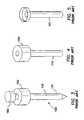
- FIG. 9is a perspective view of a prior art cannula having an uninflated balloon at the distal end
- FIG. 10is a perspective view of a prior art cannula having an inflated balloon at the distal end;
- FIG. 11illustrates a prior art trocar-cannula having a distal retention balloon placed through a body wall in a first position
- FIG. 12illustrates a prior art trocar-cannula having a distal retention balloon placed through a body wall in a second position
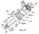
- FIG. 13is a perspective view of a balloon trocar having a bolster
- FIG. 14is a perspective view of a cannula portion of the balloon trocar of FIG. 13 ;
- FIG. 15is a perspective view of a sleeve portion of the balloon trocar of FIG. 13 ;
- FIG. 16is a partial plan view in cross section depicting the cannula portion, the sleeve portion, a seal, and an obturator of the balloon trocar of FIG. 13 ;
- FIG. 17illustrates a cannula assembly of the present invention placed through a body wall
- FIG. 18is a partial plan view in cross section similar to FIG. 16 and including a port portion of the sleeve portion of the balloon trocar;
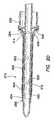
- FIG. 19is a partial plan view in cross section depicting a distal portion of the cannula portion, sleeve portion, obturator and a balloon coupled between the cannula portion and sleeve portion by windings of thread;
- FIG. 20is a plan view in cross section depicting the balloon trocar
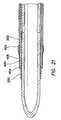
- FIG. 21is a partial plan view in cross section depicting a distal portion of the cannula portion, sleeve portion, obturator and the balloon coupled between the cannula portion and sleeve portion with a balloon having a second layer;
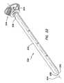
- FIG. 22is a perspective view of the obturator
- FIG. 23is a perspective view of a base portion of the bolster of FIG. 13 ;
- FIG. 24is a perspective view of a collar portion of the bolster of FIG. 13 ;
- FIG. 25is a perspective view of a lever portion of the bolster of FIG. 13 ;
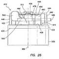
- FIG. 26is a side view of the bolster of FIG. 13 ;
- FIG. 27is a perspective view of the bolster coupled to the sleeve portion of the balloon trocar;
- FIG. 28is an end perspective view of the bolster of FIG. 13 ;
- FIG. 29is a plan view, in cross section of a sleeve portion of the balloon trocar of FIG. 13 with an inner surface of the sleeve including channels.
- a typical laparoscopic procedureis illustrated where a plurality of trocars 100 are placed through a body wall 50 , such as an abdominal wall, and into a body cavity 52 , such as an abdominal cavity.
- the body cavity 52is insufflated, or inflated with gas, to distend the body wall 50 and provide a working space for the laparoscopic procedure.
- the trocars 100each include a cannula 110 and a seal 150 . Positive pressure is maintained within the body cavity 52 by the seal 150 associated with the cannula 110 .
- the cannula 110must form a gas-tight seal against adjacent tissue. If positive pressure is lost, either through the seal 150 associated with the cannula 110 or the seal between the cannula and the adjacent tissue, the procedure may be compromised.
- the body wall 50may be greatly distended.
- the access sitesmay tend to enlarge under the distention of the body wall 50 and compromise the positioning and sealing of the cannula 110 .
- the manipulation of instruments 190 used through the trocars 100may result in movement of the cannulas 110 in either a proximal or distal direction within the access site through the body wall 50 . As this occurs, some liquefaction may take place and the preferred relationship between the cannula 110 and the body tissue may be compromised.
- a typical assembled trocar 100is shown having a cannula 110 , a seal housing 150 and an obturator 160 .
- the cannula 110typically has a smooth exterior surface 102 so that it may be inserted through the body wall 50 easily.
- the seal housing 150contains a seal system that prevents retrograde gas-flow.
- the obturator 160is a cutting or piercing instrument that creates the pathway through the body wall 50 through which the cannula 110 follows. Surgical obturators 160 are generally sized and configured to create a defect in tissue that is appropriate for the associated cannula 110 .
- the defectmay have a tendency to enlarge during a surgical procedure as the trocar 100 or cannula 110 is manipulated.
- the cannula 110may move or even be inadvertently withdrawn due to the friction between the instrument 190 and the seal 150 of the trocar housing.
- a trocar 100 or access devicewhere the outer surface 102 of the cannula 110 includes a plurality of raised features 115 .
- These raised features 115are sized and configured to increase resistance to proximal and distal motion as instruments 190 are maneuvered, and especially as specimens are removed, through the trocar 100 .
- the prior artincludes either sequential raised rings or a raised coarse-thread 115 . While the rings or threads 115 of the prior art may stabilize the cannula 110 to some degree, they do not necessarily seal the cannula 110 against the adjacent tissue of a body wall 50 . There may be gas loss associated with the use of these systems.
- the raised rings or threads 115also increase the insertion force required to penetrate a body wall 50 .
- the insertion forcemay be reduced in the instance of a continuous coarse thread 115 in comparison to a sequence of discrete raised rings or features as a threaded cannula 110 may actually be “screwed” into the tissue defect in accordance with the thread direction and pitch, rather than pushed through without appropriate rotation.
- a surgical access device 100includes a cannula 110 having an inflatable balloon 120 associated with the distal-end portion 122 of the cannula.
- the balloon 120is sized and configured to fit snugly around the cannula 110 in the uninflated condition.
- the balloon 120is inflated after the cannula 110 is properly placed through the body wall 50 and into the body cavity 52 .
- the balloon 120is generally held against the interior surface 54 of the body wall 50 by a counter-force that is associated with a sliding counter-force member, such as a foam bolster 180 .
- the bolster 180is associated with the proximal portion of the cannula 110 .
- the balloons 120 associated with the devices of the prior artare typically “thick-walled” structures constructed as part of the cannula 110 .
- the balloon 120is generally bonded to the distal-end portion 122 of the cannula 110 and an inflation channel or lumen is provided within the wall of the cannula 110 .
- one embodiment of the balloon trocar 200includes a cannula assembly 210 , a trocar seal 220 and an obturator 230 .
- the cannula assembly 210includes a cannula 250 and an outer sleeve 300 .
- the cannula 250includes a substantially longitudinal tube 252 having a proximal end 254 , a distal end 256 , and a lumen 258 therebetween.
- the cannula 250may include at least a proximal portion 260 having a first, larger periphery and a distal portion 262 having a second, smaller periphery.
- the proximal portion 260 and distal portion 262 of the cannula 250may each include a substantially cylindrical portion, with the proximal portion 260 having a first, larger circumference and the distal portion 262 having a second, smaller circumference.
- the cannula 250may also include a transition region 264 between the proximal portion 260 and the distal portion 262 .
- the lumen 258 of the cannula 250may be substantially smooth and configured to accept the obturator 230 (see FIG. 13 ).
- the proximal portion 260 of the cannula 250may be configured to accept the trocar seal 220 (see FIG. 13 ).
- the outer surface of the distal portion 262 of the cannula 250includes an annular groove 266 toward the distal end 256 of the distal portion of the cannula.
- the annular groove 266may lie within a plane that is substantially perpendicular to a longitudinal axis 272 of the cannula 250 .
- the outer surface of the distal portion 262 of the cannula 250includes a plurality of channels 268 extending along the length of the cannula from substantially the proximal end of the distal portion of the cannula distally to a point proximal to the annular groove 266 near the distal end 256 of the distal portion of the cannula.
- the plurality of channels 268is adapted to facilitate the flow of gasses or fluids therethrough.
- the plurality of channels 268may include a plurality of substantially longitudinal grooves 270 that are substantially parallel to the longitudinal axis 272 of the cannula 250 .
- the cannula 250may be made of a polymeric material, such as a polycarbonate material.
- the outer sleeve 300 of the cannula assembly 210includes a substantially longitudinal tube 302 having a proximal end 304 , a distal end 306 , and a lumen 308 therebetween.
- the sleeve 300may also include at least a proximal portion 310 having a first, larger periphery and a distal portion 312 having a second, smaller periphery.
- the proximal portion 310 and distal portion 312 of the sleeve 300may each include a substantially cylindrical portion, with the proximal portion 310 having a first, larger circumference and the distal portion 312 having a second, smaller circumference.
- the sleeve 300may include a transition region 314 between the proximal portion 310 and the distal portion 312 .
- the lumen 308 of the sleeve 300is configured to accept the cannula 250 (see FIG. 13 ) and may be substantially smooth.
- An outer surface 322 of the distal portion 312 of the sleeve 300includes an annular groove 316 toward the distal end 306 of the distal portion of the sleeve.
- the annular groove 316may lie within a plane that is substantially perpendicular to a longitudinal axis 320 of the sleeve 300 .
- the sleeve 300may be made of a polymeric material, such as a polycarbonate.
- the proximal portion 310 of the sleeve 300fits over at least a distal region of the proximal portion 260 of the cannula and the distal portion 312 of the sleeve fits over at least a portion of the distal portion 262 of the cannula.
- the distal end 306 of the sleeve 300is positioned proximal to a distal end of the plurality of channels 268 on the outer surface of the cannula 250 .
- the cannula assembly 210includes the cannula 250 and the sleeve 300 .
- a sealsuch as an o-ring 350 , may be positioned between the cannula and the sleeve.
- the sealsuch as the o-ring 350 , is positioned between the outer surface of the cannula 250 and the inner surface of the sleeve 300 .
- the outer surface of the distal region of the proximal portion 260 of the cannula 250may include a substantially flat surface, such as a planar surface or a chamfered surface, which communicates between the proximal portion 260 of the cannula and either the transition region 264 or the distal portion 262 of the cannula.
- the inner surface of the distal region of the proximal portion 310 of the sleeve 300may include a substantially flat surface, such as a planar surface or a chamfered surface, which communicates between the proximal portion 310 of the sleeve and either the transition region 314 or the distal portion 312 of the sleeve.
- the sealsuch as the o-ring 350 , is positioned between the flat surface on the outer surface of the distal region of the proximal portion 260 of the cannula 250 and the flat surface on the inner surface of the distal region of the proximal portion 310 of the sleeve 300 .
- the cannula 250 and the sleeve 300are coupled together at the proximal portion 260 of the cannula and the proximal portion 310 of the sleeve at a position proximal to the seal, such as the o-ring 350 .
- the means for coupling the proximal portion 260 of the cannula 250 and the proximal portion 310 of the sleeve 300includes a snap fitting 360 having at least one projection 362 on the outer surface of the cannula and at least one notch 364 on the inner surface of the sleeve.
- the projectionmay be on the inner surface of the sleeve and the notch may be on the outer surface of the cannula.
- the at least one projection 362 and the at least one notch 364are positioned such that when the projection is positioned within the notch, the seal, such as the o-ring 350 , is compressed sufficiently to form a seal between the cannula 250 and the sleeve 300 .
- the seal, such as the o-ring 350is made from a soft, compressible material.
- the o-ring 350is made of a silicone having a hardness of about 40 Shore A.
- the snap fitting 360includes two projections 362 positioned substantially circumferentially opposite each other on the outer surface of the cannula and two notches 364 positioned substantially circumferentially opposite each other on the inner surface of the sleeve 300 .
- Other means for coupling the sleeve 300 to the cannula 250may also be used, such as other mechanical means or adhesive bonding.
- the cannula assembly 210also includes a locking means 370 to substantially prevent, or minimize, the cannula 250 and the sleeve 300 from rotating relative each other about the longitudinal axes 272 , 320 while the cannula and sleeve are coupled together.
- the locking means 370includes a projection 372 on the outer surface of the cannula 250 and a channel 374 on the inner surface of the sleeve 300 .
- the projection 372is positioned on the outer surface of the proximal portion 260 of the cannula 250 and the channel 374 is positioned on the inner surface of the proximal portion 310 of the sleeve 300 and extends to the proximal end 304 of the sleeve.
- the projection 372may be positioned on the inner surface of the proximal portion 310 of the sleeve 300 and the channel 374 may be positioned on the outer surface of the proximal portion 260 of the cannula 250 .
- the channel 374may either be through the entire thickness of the wall of the sleeve or through only a portion of the thickness of the wall of the sleeve.
- the channel 374is substantially longitudinal and substantially parallel to the axis 320 of the sleeve 300 .
- the projection 372may include any shape that fits within the walls of the channel 374 and facilitates the prevention or minimization of rotation between the cannula 250 and the sleeve 300 .
- the projection 372is substantially cylindrical while in another embodiment the projection is substantially rectangular.
- the cannula assembly 310also includes a balloon 400 .
- the balloonincludes a tubular sleeve 402 .
- the tubular sleeve 402may include an elastomeric material.
- Elastomeric materials that may be used to make the balloon 400include silicone, polyisoprene, and urethane.
- the balloon 400may be made of other materials, such as MYLAR, that may be folded onto the cannula 250 and sleeve 300 and inflated into a larger profile.
- the balloon 400may be cut to length prior to installation onto the cannula 250 and sleeve 300 such that the balloon is sufficiently long to extend between and cover the annular grooves 266 , 316 at the distal portions 262 , 312 of the cannula and sleeve.
- the balloon 400is slid over the distal end 256 of the cannula 250 and the distal end 306 of the sleeve 300 until it covers the annular grooves 266 , 316 in the cannula and sleeve.
- the balloon 400is fixed in place by winding thread 404 around the balloon in the areas that overlap of the annular grooves 266 , 316 at the distal portions 262 , 312 of the cannula 250 and sleeve 300 .
- Winding the balloon 400 with thread 404forces the portion of the balloon that overlaps the annular grooves 266 , 316 into the annular grooves and holds the balloon in place, thereby substantially preventing longitudinal, axial movement of the balloon along the cannula assembly.
- the grooves 266 , 316are of sufficient depth that forcing the balloon 400 into the annular grooves 266 , 316 makes the balloon and winding 404 substantially flush to the cannula 250 and sleeve 300 at the windings, thereby making the cannula assembly 210 substantially smooth. Furthermore, forcing the balloon 400 into the annular grooves 266 , 316 with the windings 404 also forms a seal between the balloon and the cannula 250 and between the balloon and the sleeve 300 .
- the space between the outer surface of the cannula 250 with the channels 268 (see FIG. 14 ), the inner surface of the sleeve 300 , the o-ring 350 , and the balloon 400 with the windings 404form a substantially closed chamber 408 .
- the channels 268 on the outer surface of the cannula 250are formed into the wall of the cannula so as not to increase the overall thickness of the wall of a standard cannula.
- the lumen 308 of the sleeve 300may be configured to provide minimal space between the distal portion 312 of the sleeve and the distal portion 262 of the cannula 250 , thereby minimizing the overall profile of the cannula assembly 210 .
- the gap between the transition regions 264 , 314 of the cannula 250 and the sleeve 300may be larger than the gap between the distal portions 262 , 312 in order to more evenly distribute gas or fluid through the channels 268 on the outer surface of the cannula 250 during inflation and deflation of the balloon.
- the balloon 400may be made to take on one of many different shapes upon inflation of the balloon.
- the balloon 400may include a substantially toroid shape upon inflation.
- the balloonmay include a disc shape upon inflation.
- the balloon 400may be a fluted balloon.
- different shapes for the balloon 400may be attained by varying the thickness about the tubular sleeve 402 that forms the balloon or by pre-molding a different shape for the balloon.
- the balloon 400should have sufficient impermeability properties to substantially prevent inflation gas or fluid from permeating through a wall of the balloon. Additionally, the balloon should bias toward a deflated state during deflation of the balloon.
- an outer layer 406may be positioned and fixed over the balloon.
- the outer layer 406may include silicone, latex, polyisoprene, rubber, or other biocompatible elastomeric materials that are well known in the art.
- the outer layer 406may be wound onto the cannula 250 and sleeve 300 together with the balloon 400 , as described above.
- the sleeve 300includes an inflation port 380 positioned to be distal to the seal, such as the o-ring 350 .
- the inflation port 380provides a pathway for gas or fluid to be introduced and removed from the chamber 408 .
- the inflation port 380may include a normally closed check valve 382 having a spring-loaded plunger 384 .
- the check valve 380may include a Luer lock 386 . It is contemplated that other inflation ports that are well known in the art may be used.
- the trocar seal 220may include a valve that provides an instrument seal in the presence of an instrument, such as the obturator 230 , and a zero-seal in the absence of an instrument.
- the trocar seal 220may also be removable from the cannula assembly 210 . Removal of the trocar seal 220 is useful for tissue removal through the cannula assembly 210 and for rapid release of insufflation gasses.
- the obturator 230includes an elongate shaft 232 extending along a substantially longitudinal axis 234 between a proximal end 236 and a distal end 238 .
- a distal tip 240 of the elongate shaft 232may include a prolate spheroid shape.
- the elongate shaft 232including the distal tip 240 , is sized and configured to slide within the lumen 258 of the cannula 250 (see FIGS. 16 and 19 ).
- a proximal portion 242 of the obturator 230may include a handle portion 244 having a larger periphery than the elongate shaft 232 to facilitate advancing and retracting the obturator within the lumen 258 of the cannula 250 .
- the distal tip 240 of the obturator 230is positioned distal to the distal end 256 of the cannula 250 and the handle portion 244 of the obturator is positioned proximal to the proximal end 254 of the cannula.
- the obturator 230may be made of a polymeric material, such as a polycarbonate. Those familiar with the art will recognize that the obturator 230 may be made of other materials that are well known in the art and are considered within the scope of the present invention. In comparison to obturators having distal tips with a spheroid shape, the distal tip 240 of the obturator 230 having a prolate spheroid shape requires a lower insertion force to insert the trocar into a body through an incision within a body wall.
- the prolate spheroid shape of the distal tip 240 of the obturator 230also reduces the likelihood of injuring tissue or organs within the body cavity, in comparison to obturators having distal tips with a more pointed shape.
- the surgeoncan merely nick the peritoneum and dilate or stretch the incision open with the distal tip of the obturator.
- a bolster 410may be used in conjunction with the balloon trocar 200 to assist the balloon to seal around an incision in the body wall 50 through which the balloon trocar is to be inserted with the balloon sealing the incision from within the body cavity 52 .
- the bolster 410is configured to perform as a cannula fixation device on the outside of the body while the balloon 400 acts as a cannula fixation device on the inside of the body.
- the bolster 410is slidably adjustable along the length of the cannula assembly 210 proximal to the balloon 400 and includes a clamping device for locking the bolster in position along the length of the cannula assembly.
- the balloon 400on the other hand, is fixed at a location along the length of the cannula assembly 210 and seals against the inner surface of the abdominal wall.
- the bolsterincludes a base 420 and a clamping mechanism 415 .
- the clamping mechanism 415includes an adjustable collar 460 and a lever 500 .
- the bolsteralso includes a pad 530 including a substantially incompressible gel material.
- the clamping featuresutilize an over-center lock design to maintain the bolster 410 in a fixed position along the length of the cannula assembly 210 .
- the base 420includes a sleeve 422 projecting distally from a flange 424 .
- the flange 424includes a proximal surface 428 and a distal surface 430 .
- the proximal surface 428 and the distal surface 430 of the flange 424are substantially parallel to each other and substantially perpendicular to an axis 432 of the base 420 .
- the flange 424is shown as being flat, other shapes, such as rounded shapes, may be used and are contemplated as within the scope of the invention.
- the sleeve 422 portion of the base 420includes a proximal end 434 , a distal end 436 , and a lumen 438 therebetween.
- the lumen 438is sized to receive and slidably engage the sleeve 300 of the cannula assembly 210 .
- An outer surface 440 of the sleeve 422 portion of the base 420may include a substantially cylindrical shape.
- the lumen 438 of the sleeve 422 portion of the base 420extends through the flange 424 , thereby forming an aperture 442 in the flange.
- a clamp receptacle 444extends proximally from the proximal surface 428 of the flange 424 .
- the clamp receptacle 444includes at least one riser 446 extending from the proximal surface 428 of the flange 424 and a platform 448 extending from the at least one riser 446 .
- the clamp receptacle 444includes a first riser 450 and a second riser 452 with the platform 448 extending between the first and second risers.
- the platform 448is shaped so as to not extend over the aperture 442 in the flange 424 .
- the platform 448provides clearance for the cannula assembly 210 such that the bolster 410 may slidably engage the cannula assembly without the platform interfering with the engagement.
- the platform 448includes a distal surface 454 that is substantially parallel to the proximal surface 428 of the flange 424 . As will be described below, the distance between the distal surface 454 of the platform 448 and the proximal surface 428 of the flange 424 is sufficient to receive the clamp mechanism 415 portion of the bolster 410 .
- the distal surface 454 of the platformincludes a substantially linear slot 456 extending radially therethrough.
- the basemay be made of a polymeric material, such as a polycarbonate. However, it is contemplated that other materials, such as metals and composites, may be used.
- the collar 460 portion of the clamping mechanism 415 of the bolster 410includes a substantially circumferential ring 462 defining a split 464 .
- the collar 460further includes a proximal end 466 , a distal end 468 , and an inner surface 470 .
- the inner surface 470 of the collar 460may include a counterbore configuration forming a ledge 472 therein.
- the split 464 in the collar 460forms a first end 474 of the collar 460 and a second end 476 of the collar.
- the collar 460is flexible in order to adjust the fit of the collar over the cannula assembly 210 .
- first end 474 and the second end 476 of the collarmay be brought closer together to create sufficient friction between the bolster 410 and the cannula assembly 210 to substantially fix the bolster in place along the length of the cannula assembly.
- the first end 474 and the second end 476 of the collarmay also be spread apart to reduce or substantially eliminate the friction between the bolster 410 and the cannula assembly 210 so that the bolster may slide along the length of the cannula assembly.
- a first tab 478extends from the first end 474 of the collar and a second tab 480 extends from the second end 476 of the collar.
- the first and second tabs 478 , 480may extend circumferentially from the first and second ends 474 , 476 , respectfully.
- the first and second tabs 478 , 480may extend tangentially or radially from the first and second ends 474 , 476 , respectfully, or in any other manner that is well known in the art.
- the first tab 478includes a first aperture 482 extending longitudinally therethrough and the second tab 480 includes a second aperture 484 extending longitudinally therethrough.
- the first and second apertures 482 , 484extend substantially parallel to an axis 486 of the collar 460 .
- the lever 500interacts with the tabs 478 , 480 to control the distance between the first and second ends 474 , 476 of the collar 460 .
- the collarmay be made of a polymeric material, such as polycarbonate. However, it is contemplated that other materials, such as metals and composites, may be used.
- the lever 500includes an arm 502 having a first, proximal surface 504 , a second, distal surface 506 , a first end 508 and a second end 510 .
- the proximal and distal surfaces 504 , 506 of the arm 502are substantially parallel to each other.
- a substantially cylindrical first pin 512extends proximally from the proximal surface 504 of the arm 502 proximate the first end 508 and a substantially cylindrical second pin 514 extends distally from the distal surface 506 proximate the first end.
- the first and second pins 512 , 514each extend substantially perpendicular from the proximal and distal surfaces 504 , 506 , respectively, of the arm 502 .
- An axis 516 of the first pin 512 and an axis 518 of the second pin 514are substantially parallel to each other, but are also offset from each other.
- the first pin 512is closer to the first end 508 of the arm 502 than is the second pin 514 .
- the peripheries of the first and second pins 512 , 514are sized to fit within the first and second apertures 482 , 484 , respectively, of the tabs 478 , 480 of the collar 460 .
- the distal surface of the first tab 478 of the collar 460 and a proximal surface of the second tab 480 of the collarare substantially flat, substantially parallel to each other and substantially perpendicular to the axis 486 of the collar 460 .
- the space 488is sized to receive the arm 502 of the lever 500 .
- the lever 500is coupled to the collar 460 by manipulating the arm 502 of the collar into the space 488 between the first and second tabs 478 , 480 of the collar and inserting the first pin 512 of the lever into the first aperture 482 (see FIG.
- the lever 500is pivotally coupled to the collar 460 .
- the first pin 512 of the leveris sufficiently long to extend beyond the proximal surface of the first tab 478 of the collar 460 , while the second pin 514 is substantially flush or below flush with the distal surface of the second tab 480 of the collar.
- the collar and leverare inserted into the clamp receptacle 444 portion of the base. More particularly, the clamping mechanism 415 is inserted between the proximal surface 428 of the flange 424 portion of the base 420 and the distal surface 454 of the platform 448 of the clamp receptacle 444 portion of the base such that the collar 460 is nested between the flange 424 , the platform 448 , and the at least one riser 446 portion of the clamp receptacle 444 .
- first and second tabs 478 , 480 of the collar 460 and the first and second pins 512 , 514 (see FIGS. 24 and 25 ) of the lever 500are positioned between the proximal surface 428 of the flange 424 portion of the base 420 and the distal surface 454 of the platform 448 .
- the distance between the proximal surface 428 of the flange 424 portion of the base 420 and the distal surface 454 of the platform 448is sufficient for the clamp mechanism 415 to slidably engage within the clamp receptacle 444 , yet also sufficiently low to maintain the lever 500 and collar 460 of the clamp mechanism 415 in an engaged relationship with each other during activation of the lever to maintain the clamping force of the collar against the cannula assembly 210 .
- the first pin 512 of the lever 500which extends proximally beyond the proximal surface of the first tab 478 , is positioned within the slot 456 on the distal surface 454 of the platform 448 to facilitate maintaining the position of the first and second tabs 478 , 480 of the collar 460 and the first and second pins 512 , 514 of the lever 500 between the proximal surface 428 of the flange 424 portion of the base 420 and the distal surface 454 of the platform 448 .
- the bolster 410is slidably mounted onto the cannula assembly 210 by inserting the distal end 256 of the cannula distally through the proximal end 466 of the collar 460 , through the aperture 442 (see FIG. 23 ) of the flange 424 of the base 420 , and through the sleeve 422 (see FIG. 23 ) of the base.
- the bolster 410 and cannula assembly 210are slid relative to each other until the distal end 436 of the sleeve 422 (see FIG. 23 ) of the base 420 is proximal to the balloon 400 (see FIG. 19 ).
- the distance between the first and second ends 474 , 476 of the collaris at its maximum when the lever is in a first, clockwise position.
- Rotating the lever 500 in a counter clockwise directionmoves the first and second ends 474 , 476 of the collar 460 closer together, reducing the circumference of the collar and tightening the collar against the cannula assembly 210 (see FIG. 13 ).
- the change in circumference of the collar 460 as the lever 500 is rotatedis caused by the offset between the first pin 512 and the second pin 514 of the lever (see FIG. 25 ).
- the circumference of the collar 460is at its smallest when the lever is rotated about 180° from the first position.
- the lever 500is rotated from the first position more than about 180° to a second position. In this manner, as the lever 500 is rotating from the first position, the circumference of the collar 460 reduces until the lever has rotated about 180°, then expands slightly until the lever is positioned at the second position. With the lever 500 in the second position, higher pressure is initially required to rotate the lever away from the second position in a clockwise direction to the first position because the circumference of the collar 460 is reduced until the lever reaches the position that is about 180° from the first position. The higher pressure that is required protects against inadvertent release of the clamp mechanism 415 .
- the clamp mechanism 415was described in detail, those familiar in the art will recognize that other clamp mechanisms that are well known in the art may be used with satisfactory results.
- the inner surface 470 of the collarclamps directly against an outer surface 322 of the sleeve 300 portion of the cannula assembly 210 .
- the bolster 410includes a compressible ring 490 positioned inside the collar 460 .
- the ring 490may be seated against the ledge 472 on the inner surface 470 of the collar 460 .
- the inner surface 492 of the ring 490is sized to permit the bolster 410 to slide along the cannula assembly 210 when the lever 500 is in the first position and to be compressed against the outer surface 322 of the sleeve 300 portion of the cannula assembly when the lever is in the second position.
- the compressed ring 490ensures that there is sufficient friction between the bolster 410 and the cannula assembly 210 when the lever is in the second position to maintain the position of the bolster along the cannula assembly.
- the ring 490is made of an incompressible elastomeric material, such as silicone.
- the ring 490is molded from a soft elastomeric material, such as a silicone having a hardness of about 40 Shore A durometer.
- the ring 490makes the collar 460 substantially self-centering around the cannula assembly 210 .
- Having the first pin 512 of the lever 500 extending into the slot 456 on the distal surface 454 of the platform 448substantially prevents the clamping mechanism 415 from rotating about the base 420 when the bolster is positioned on the cannula assembly 210 and the lever 500 is in the second position. This in turn substantially prevents the bolster 410 from rotating about the cannula assembly 210 .
- the bolster 410includes a substantially annular gel pad 530 coupled to the distal surface 430 of the flange 424 portion of the base 420 and around the outer surface 440 of the sleeve 422 (see FIG. 23 ) portion of the base.
- the gel 530is substantially incompressible. Since the gel pad 530 is substantially incompressible, it does not need to be as thick as the foam pads 180 of the prior art. Having a thinner pad provides the cannula assembly 210 with more usable length.
- the gel pad 530may operate as a backup seal for the incision to help protect against leaks that might develop between the balloon and the inner surface of the body wall.
- the gel pad 530may be between about 3.0-20.0 mm thick.
- the gel pad 530may be thicker to promote the sealing features of the gel pad.
- the gel pad 530is made of a gel and may be attached to, formed or integrated with the base 420 .
- the gelis an elastomeric gel.
- the gelcan be prepared by mixing a triblock copolymer with a solvent for the midblocks.
- the endblocksare typically thermoplastic materials such as styrene and the midblocks are thermoset elastomers such as isoprene or butadiene, e.g., Styrene-Ethylene-Butylene-Styrene (SEBS).
- SEBSStyrene-Ethylene-Butylene-Styrene
- the solvent usedis mineral oil. Upon heating this mixture or slurry, the midblocks are dissolved into the mineral oil and a network of the insoluble endblocks forms.
- the resulting networkhas enhanced elastomeric properties over the parent copolymer.
- the triblock copolymer usedis KRATON G1651.
- the gelis substantially permanent and by the nature of the endblocks processable as thermoplastic elastomers henceforward.
- the mixture or slurryhas a minimum temperature at which it becomes a gel, i.e., the minimum gelling temperature (MGT).
- MGTminimum gelling temperature
- This temperaturein one aspect corresponds to the glass transition temperature of the thermoplastic endblock plus a few degrees.
- the MGT for the mixture of KRATON G1651 and mineral oilis about 120° C.
- the entire mass of the slurryis heated to the MGT and remains heated at the MGT for sufficient time for the end blocks to form a matrix of interconnections.
- the slurrywill continue to form into gel at temperatures above the MGT until the slurry/gel reaches temperatures at which the components within the slurry/gel begin to decompose or oxidize.
- the mineral oil in the slurry/gelwill begin to be volatile and oxidize. Oxidizing may cause the gel to turn brown and become oily.
- the speed at which a given volume of slurry forms a gelis dependant on the speed with which the entire mass of slurry reaches the MGT. Also, with the application of temperatures higher than the MGT, this speed is further enhanced as the end block networks will distribute and form more rapidly.
- KRATON G1701Xis a 70% SEB 30% SEBS mixture with an overall Styrene to rubber ratio of 28/72. It can be appreciated that an almost infinite number of combinations, alloys, and Styrene to rubber ratios can be formulated, each capable of providing advantages to a particular embodiment of the invention. These advantages will typically include low durometer, high elongation, and good tear strength.
- the gel materialmay also include silicone, soft urethanes and even harder plastics with the addition of a foaming agent that provide the desired qualities for the bolster to assist the balloon 400 to seal against the inner surface of the body wall 52 .
- the silicone materialmay be of the types currently used for electronic encapsulation.
- the harder plasticsmay include PVC, Isoprene KRATON neat, and other KRATON/oil mixtures. In the KRATON/oil mixture, oils such as vegetable oils, petroleum oils and silicone oils may be substituted for the mineral oil.
- any of the gel materials contemplatedcould be modified to achieve different properties such as enhanced lubricity, appearance, and wound protection.
- Additivesmay be incorporated directly into the gel or applied as a surface treatment.
- Other compoundsmay be added to the gel to modify its physical properties or to assist in subsequent modification of the surface by providing boding sites or a surface charge.
- oil based colorantsmay be added to the slurry to create gels of different colors.
- the mixture/slurry used with the various embodiments of the bases 420 that are described hereinare composed of 90% by weight of mineral oil and 10% by weight of KRATON G1651. From a thermodynamic standpoint, this mixture behaves similar to mineral oil. Mineral oil has a considerable heat capacity and therefore at about 130° C. it can take 3 or 4 hours to heat a pound of the slurry sufficiently to form a homogeneous gel. Once formed, the gel can be cooled as quickly as practical with no apparent deleterious effects on the gel. This cooling, in one aspect, is accomplished with cold-water immersion. In another aspect the gel may be air-cooled. Those familiar with the art will recognize that other cooling techniques that are well know in the art may be employed and are contemplated as within the scope of the present invention.
- KRATON/oil mixtureMany of the properties of the KRATON/oil mixture will vary with adjustments in the weight ratio of the components. In general, the greater the percentage of mineral oil, the less firm the mixture; the greater the percentage of KRATON, the more firm the mixture.
- the copolymersuch as KRATON
- the solventsuch as mineral oil
- the slurrymay be mixed, such as with high shear blades, to make the slurry more homogeneous. However, mixing the slurry may introduce or add air to the slurry.
- the slurrymay be degassed.
- the slurrymay be degassed in a vacuum, such as within a vacuum chamber. In one aspect, the applied vacuum may be 0.79 meters (29.9 inches) of mercury, or about 1.0 atmosphere.
- the slurrymay be stirred while the slurry is under vacuum to facilitate removal of the air.
- the slurrytypically expands, then bubbles, and then reduces in volume.
- the vacuummay be discontinued when the bubbling substantially ceases.
- Degassing the slurry in a vacuum chamberreduces the volume of the slurry by about 10%. Degassing the slurry helps reduce the potential of the finished gel to oxidize.
- Degassing the slurrytends to make the resultant gel firmer.
- a degassed slurry composed of about 91.6% by weight of mineral oil and 8.4% by weight of KRATON G1651, an eleven-to-one ratioresults in a gel having about the same firmness as a gel made from a slurry that is not degassed composed of 90% by weight of mineral oil and 10% by weight of KRATON G1651, a nine-to-one ratio.
- the gel in various aspects of the present inventionmay be gamma sterilized.
- the relative or comparative simplicity of qualifying the sterilization processfor example of gamma versus ethylene oxide, of the gel and the device with the gel is desirable.
- large bubblescan form in the gel causing potential cosmetic or aesthetic issues in the sterilized devices.
- the bubblesare more than 99% room air and as such removal of the dissolved air in the slurry prior to forming the slurry into gel is performed.
- the slurrymay be degassed via vacuum as described above and turned into gel by heat. Bubbles may still form in the gel during gamma sterilization but disappear in a period of about 24 to 72 hours.
- the percentage of dissolved gas in the mineral oil at room temperatureis about 10%.
- the removal of the air in the gelhas an additional effect of making the gel firmer. This however is counterbalanced by the softening effect of gamma radiation on the gel during gamma sterilization.
- the gelmay include about 90% mineral oil by weight and about 10% KRATON by weight.
- degassing the slurryhas the effect of making the gel firmer, however, the gamma radiation softens the gel to substantially the same firmness as a gel having about 90% mineral oil by weight and about 10% KRATON by weight that is not degassed or gamma sterilized.
- cyanoacrylatee.g., SUPERGLUE or KRAZY GLUE
- the gluemay attach to either the rubber or styrene component of the tri-block and the bond is frequently stronger than the gel material itself.
- a solventis used to dissolve the plastics in the base 420 and the polystyrene in the gel.
- the solution of solventis applied to the gel and base 420 in either a spray or dip form. In effect the solution melts both the plastic of the base as well as the polystyrene in the gel to allow a chemical bond to form between the two, which remains when the solvent evaporates.
- Polyethylenecan be dissolved in mineral oil and then applied to the gel.
- the mineral oilwill not evaporate but will over time absorb into the gel and impart a polyethylene layer on the gel that may have beneficial properties.
- the gelis cast into a mold containing the base 420 .
- Adhesion between the gel pad 530 and the base 420can be achieved by using KRATON polymer or a similar material in the base.
- the polystyrene in the gelis identified as achieving adhesion with polyphenylene oxide (PPO), polystyrene and others.
- the gel pad 530 and the base 420are heated to a temperature above about 130° C. and held at that temperature for several hours, e.g., about 3 to 4 hours.
- the temperature usedis not sufficient to deform the base 420 .
- the base 420comprises a polymer, e.g., polyethylene (PE).
- PEpolyethylene
- the polyethyleneis a low-density polyethylene (LDPE) or high-density polyethylene (HDPE), or ultra high molecular weight polyethylene (UHMWPE).
- LDPElow-density polyethylene
- HDPEhigh-density polyethylene
- UHMWPEultra high molecular weight polyethylene
- the base 420may be made of a polymer, such as polycarbonate and may be fabricated by methods including injection molding.
- the gelincludes mineral oil.
- PEhas a higher molecular weight than mineral oil.
- PEis dissolved by mineral oil at high temperatures. As such, as the PE and mineral oil in the gel intermix as both are heated to and held at temperatures above about 130° C., a bond between the PE and gel is formed.
- the base 420is made of polycarbonate.
- the polycarbonate of the basedoes not form bonds with gel at 130° C. However during casting, by raising the temperature to about 150° C. for a few minutes, bonding occurs between the gel pad 530 and the base. As such, heating the gel and base to temperatures at which both the polystyrene of the gel and the polycarbonate are simultaneously beyond their melt points allows bonds to form between the gel pad 530 and the base 420 .
- the gel and basemay be heated to near or at the glass transition temperature of the polycarbonate base 420 to form the bond between the gel pad 530 and the base.
- casting the gel pad 530 with the base 420 to form the bolster 410includes placing the base into a casting mold.
- the moldmay be made of aluminum, copper, brass, or other mold material having good heat dissipation properties. However, those familiar with the art will recognize that other mold materials having lower heat dissipation properties will produce acceptable parts and these are contemplated as within the scope of the present invention.
- the mold having the base 420is filled with the slurry.
- the slurrymay be preheated, for example, to about 52° C. (125° F.). Preheating the slurry to a temperature below the MGT reduces the viscosity of the slurry and allows the slurry to flow more easily.
- the slurrymay have been degassed in a vacuum. The slurry may be degassed again within the mold after the mold is filled to remove air that may have been introduced during the filling of the mold and to facilitate flow of the slurry into voids in the mold.
- Heatis applied to the mold having the base 420 and the slurry, such as in an oven, until the slurry attains a temperature of about 150° C.
- the slurryturns into gel at about 120° C., however, at about 150° C., the gel can bond to a polycarbonate base 420 .
- bondingmay take place at temperatures other than about 150° C. If the base 420 is fabricated of a material having a lower melting point than 120° C., then the gel pad 530 may be molded separately and then bonded to the base 420 .
- the bolster 410may be cooled, such as by air-cooling, cold-water immersion, or other cooling means that are well known in the art. At 150° C. the gel is soft and if it were distorted during cooling it would set with the distortion included. To reduce the likelihood of distorting the gel pad 530 , the bolster 410 may be cooled within the mold. Cooling times may vary based on parameters including size and configuration of the mold, quantity of gel, temperature and quantity of cooling medium, cooling medium properties and the mold material. Whether cooling with air or water, the final properties of the gel are substantially the same.
- the bolster 410is typically cooled to about ambient room temperature, but may be cooled to lower temperatures. The bolster 410 may be removed from the mold at any time after the gel has set.
- the gelWhen removed from the mold, the gel typically has a tacky surface.
- the gel pad 530may be coated with a powder, such as cornstarch, to substantially reduce or eliminate the tackiness of the cured gel.
- the gel pad 530may be molded separately from the base 420 and subsequently bonded to the base.
- the gel pad 530may be molded into a slug. Since the gel 530 is being molded separate from the base 420 , the slurry only needs to be heated until it reaches about 120° C. and completes the transformation from slurry into gel and the gel becomes substantially transparent. The gel pad 530 may then be placed onto the base 420 . The gel pad 530 and base 420 are heated to a sufficient temperature for the polystyrene of the gel and the polymer of the base 420 to form bonds between the gel pad 530 and the base.
- Molding the gel pad 530 separately from the base 420 and heat bonding the gel pad to the base at a later timeis especially useful when the base is made of a material that has a lower melting temperature than the MGT. In such situations, the gel pad 530 can be molded first and heat bonded to the base 420 without melting the base.
- the balloon trocar 200 of the present inventionmay be used, a surgeon may gain access to the abdominal cavity 52 through the abdominal wall 50 by using the “Hassan” or “cut-down” technique.
- Hissanor “cut-down” technique.
- use of the Hassan or cut-down techniqueoften leaves a defect larger than the trocar that will be located through the incision. Therefore, it is necessary to provide a means to seal the incision after the trocar has been inserted in order to insufflate the patient's abdominal cavity.
- the balloon trocar 200 of the present inventionprovides such sealing means.
- the distal end of the balloon trocar 200is inserted through the incision until the balloon 400 at the distal portion of the cannula assembly 210 is within the body cavity.
- a syringe 540may be inserted into the port 380 and used to inflate the balloon 400 by injecting gas or fluid into the chamber 408 .
- the bolster 410may be advanced distally along the cannula while pulling the balloon trocar 200 proximally until the inflated balloon is compressed against the inner surface of the body wall 50 and the gel pad 530 is compressed against the outer surface of the body wall.
- the lever 500may be rotated to apply clamping force from the clamp mechanism 415 onto the outer sleeve 300 to maintain the position of the bolster on the cannula assembly 210 , thereby maintaining compression of the balloon 400 against the interior surface of the body wall 50 and compression of the gel pad 530 against the exterior surface of the body wall.
- the body cavity 52such as the abdominal cavity, may be insufflated with CO 2 or a similar gas.
- the plunger 384within the port 380 may be depressed to release the gas or fluid from the balloon.
- the syringe 540may be used to depress the plunger 384 within the port 380 and the syringe used to pull the gas or fluid from the chamber 408 , thereby deflating the balloon 400 .
- an inner surface 330 of the outer sleeve 300may include a plurality of channels 332 extending along the length of the outer sleeve from substantially the proximal end of the distal portion 312 of the outer sleeve distally to the distal end 306 of the outer sleeve.
- the channels 332are similar to the channels 268 described for the outer surface of the cannula 250 .
- the plurality of channels 332 on the inner surface 330 of the outer sleeve 300is adapted to facilitate the flow of gasses or fluids therethrough.
- the plurality of channels 332 on the inner surface 330 of the outer sleeve 300may include a plurality of substantially longitudinal grooves 334 that are substantially parallel to the longitudinal axis 320 of the outer sleeve.
- the sleeve 300may be used with either the cannula 250 having a plurality of channels 268 on the outer surface of the cannula to further increase the flow of gasses or fluids between the sleeve and cannula, or a cannula having a substantially smooth outer surface.
Landscapes
- Health & Medical Sciences (AREA)
- Life Sciences & Earth Sciences (AREA)
- Surgery (AREA)
- Heart & Thoracic Surgery (AREA)
- Animal Behavior & Ethology (AREA)
- General Health & Medical Sciences (AREA)
- Biomedical Technology (AREA)
- Veterinary Medicine (AREA)
- Engineering & Computer Science (AREA)
- Public Health (AREA)
- Medical Informatics (AREA)
- Pathology (AREA)
- Molecular Biology (AREA)
- Nuclear Medicine, Radiotherapy & Molecular Imaging (AREA)
- Gastroenterology & Hepatology (AREA)
- Pulmonology (AREA)
- Anesthesiology (AREA)
- Hematology (AREA)
- Biophysics (AREA)
- Surgical Instruments (AREA)
Abstract
Description
Claims (64)
Priority Applications (7)
| Application Number | Priority Date | Filing Date | Title |
|---|---|---|---|
| US11/374,188US8147453B2 (en) | 2006-03-13 | 2006-03-13 | Balloon trocar |
| US11/683,821US8287503B2 (en) | 2006-03-13 | 2007-03-08 | Balloon trocar |
| PCT/US2007/063728WO2007106750A2 (en) | 2006-03-13 | 2007-03-09 | Balloon trocar |
| EP07758288AEP2001377B1 (en) | 2006-03-13 | 2007-03-09 | Balloon trocar |
| DE602007009504TDE602007009504D1 (en) | 2006-03-13 | 2007-03-09 | Balloon trocar |
| US13/438,566US8939946B2 (en) | 2006-03-13 | 2012-04-03 | Balloon trocar |
| US14/605,536US9259238B2 (en) | 2006-03-13 | 2015-01-26 | Balloon trocar |
Applications Claiming Priority (1)
| Application Number | Priority Date | Filing Date | Title |
|---|---|---|---|
| US11/374,188US8147453B2 (en) | 2006-03-13 | 2006-03-13 | Balloon trocar |
Related Child Applications (2)
| Application Number | Title | Priority Date | Filing Date |
|---|---|---|---|
| US11/683,821Continuation-In-PartUS8287503B2 (en) | 2006-03-13 | 2007-03-08 | Balloon trocar |
| US13/438,566ContinuationUS8939946B2 (en) | 2006-03-13 | 2012-04-03 | Balloon trocar |
Publications (2)
| Publication Number | Publication Date |
|---|---|
| US20070239108A1 US20070239108A1 (en) | 2007-10-11 |
| US8147453B2true US8147453B2 (en) | 2012-04-03 |
Family
ID=38330110
Family Applications (3)
| Application Number | Title | Priority Date | Filing Date |
|---|---|---|---|
| US11/374,188Active2031-02-02US8147453B2 (en) | 2006-03-13 | 2006-03-13 | Balloon trocar |
| US13/438,566ActiveUS8939946B2 (en) | 2006-03-13 | 2012-04-03 | Balloon trocar |
| US14/605,536ActiveUS9259238B2 (en) | 2006-03-13 | 2015-01-26 | Balloon trocar |
Family Applications After (2)
| Application Number | Title | Priority Date | Filing Date |
|---|---|---|---|
| US13/438,566ActiveUS8939946B2 (en) | 2006-03-13 | 2012-04-03 | Balloon trocar |
| US14/605,536ActiveUS9259238B2 (en) | 2006-03-13 | 2015-01-26 | Balloon trocar |
Country Status (4)
| Country | Link |
|---|---|
| US (3) | US8147453B2 (en) |
| EP (1) | EP2001377B1 (en) |
| DE (1) | DE602007009504D1 (en) |
| WO (1) | WO2007106750A2 (en) |
Cited By (22)
| Publication number | Priority date | Publication date | Assignee | Title |
|---|---|---|---|---|
| US20110196205A1 (en)* | 2010-02-05 | 2011-08-11 | Tyco Healthcare Group Lp | Surgical portal locking system |
| US8888692B1 (en) | 2011-08-26 | 2014-11-18 | Applied Medical Resources Corporation | Trocar cannula assembly and method of manufacture |
| US9161839B2 (en) | 2008-12-04 | 2015-10-20 | Pivot Medical, Inc. | Method and apparatus for accessing the interior of a hip joint, including the provision and use of a novel telescoping access cannula and a novel telescoping obturator |
| US10022149B2 (en) | 2012-09-28 | 2018-07-17 | Covidien Lp | Optical trocar visualization system and apparatus |
| US10327809B2 (en) | 2016-02-29 | 2019-06-25 | Covidien Lp | Clip collar advanced fixation |
| CN110772305A (en)* | 2019-11-22 | 2020-02-11 | 温州医科大学附属第一医院 | Puncture outfit for laparoscopic surgery |
| US11357542B2 (en) | 2019-06-21 | 2022-06-14 | Covidien Lp | Valve assembly and retainer for surgical access assembly |
| US11357540B2 (en) | 2018-02-16 | 2022-06-14 | Covidien Lp | Port fixation device |
| USD956219S1 (en) | 2020-07-10 | 2022-06-28 | Covidien Lp | Port apparatus |
| USD963851S1 (en) | 2020-07-10 | 2022-09-13 | Covidien Lp | Port apparatus |
| US11446058B2 (en) | 2020-03-27 | 2022-09-20 | Covidien Lp | Fixture device for folding a seal member |
| US11541218B2 (en) | 2020-03-20 | 2023-01-03 | Covidien Lp | Seal assembly for a surgical access assembly and method of manufacturing the same |
| US11633211B2 (en) | 2020-05-01 | 2023-04-25 | Cilag Gmbh International | Pinch to release cannula depth limiter |
| US11642153B2 (en) | 2020-03-19 | 2023-05-09 | Covidien Lp | Instrument seal for surgical access assembly |
| US11712267B2 (en) | 2020-05-01 | 2023-08-01 | Cilag Gmbh International | Tilting tang cannula depth limiter |
| US11717321B2 (en) | 2020-04-24 | 2023-08-08 | Covidien Lp | Access assembly with retention mechanism |
| US11812991B2 (en) | 2019-10-18 | 2023-11-14 | Covidien Lp | Seal assemblies for surgical access assemblies |
| US11980392B2 (en) | 2020-05-01 | 2024-05-14 | Cilag Gmbh International | Pinch-to-clamp cannula depth limiter |
| US11986215B2 (en) | 2020-05-01 | 2024-05-21 | Cilag Gmbh International | Universal size multi-walled elastomer cannula depth limiter |
| US12213699B2 (en) | 2020-05-01 | 2025-02-04 | Cilag Gmbh International | Threaded cannula depth limiter |
| US12402912B2 (en) | 2020-05-01 | 2025-09-02 | Cilag Gmbh International | Multi-diameter cannula depth limiter |
| US12408944B2 (en) | 2021-01-11 | 2025-09-09 | Covidien Lp | Cannula assembly including a suction cup seal |
Families Citing this family (62)
| Publication number | Priority date | Publication date | Assignee | Title |
|---|---|---|---|---|
| JP4287273B2 (en) | 2001-09-24 | 2009-07-01 | アプライド メディカル リソーシーズ コーポレイション | Bladeless obturator |
| WO2003096879A2 (en) | 2002-05-16 | 2003-11-27 | Applied Medical Resources Corporation | Cone tip obturator |
| EP2545862B1 (en) | 2003-10-03 | 2015-09-30 | Applied Medical Resources Corporation | Bladeless optical obturator with a lock for an optical instrument |
| EP2545870B1 (en) | 2004-06-29 | 2015-11-04 | Applied Medical Resources Corporation | Insufflating optical surgical instrument |
| US20080173568A1 (en)* | 2006-09-20 | 2008-07-24 | Mohamed Brageeth | Kit suitable for use in a surgical procedure and methods for using the same |
| AU2007303069B2 (en) | 2006-10-06 | 2013-03-21 | Applied Medical Resources Corporation | Visual insufflation port |
| US8162893B2 (en) | 2008-01-15 | 2012-04-24 | Applied Medical Resources Corporation | Trocar stability assembly |
| EP2851020B1 (en)* | 2008-01-25 | 2016-01-20 | Applied Medical Resources Corporation | Insufflating access system |
| AU2009222028A1 (en)* | 2008-03-03 | 2009-09-11 | Applied Medical Resources Corporation | Balloon trocar advanced fixation |
| EP2328487B1 (en) | 2008-09-29 | 2018-04-18 | Applied Medical Resources Corporation | First-entry trocar system |
| AU2015205841B2 (en)* | 2008-10-13 | 2017-04-27 | Applied Medical Resources Corporation | Surgical access system |
| CA2739910C (en)* | 2008-10-13 | 2017-06-06 | Applied Medical Resources Corporation | Single port access system |
| GB201003817D0 (en)* | 2010-03-08 | 2010-04-21 | North Bristol Nhs Trust | Medical device |
| US9421032B2 (en)* | 2010-06-16 | 2016-08-23 | Covidien Lp | Seal port with blood collector |
| EP3106130B1 (en)* | 2011-01-31 | 2018-09-05 | St. Jude Medical, LLC | An adjustment tool for a prosthetic device |
| WO2012106351A1 (en) | 2011-01-31 | 2012-08-09 | St. Jude Medical, Inc. | Tool for the adjustment of a prosthetic anatomical device |
| ES2600924T3 (en) | 2011-01-31 | 2017-02-13 | St. Jude Medical, Inc. | Adjustable prosthetic anatomical device support element and handle for implantation of an annuloplasty ring |
| KR20140018324A (en) | 2011-05-02 | 2014-02-12 | 어플라이드 메디컬 리소시스 코포레이션 | Low-profile surgical universal access port |
| US20130041395A1 (en)* | 2011-08-09 | 2013-02-14 | Didier De Canniere | Introductory assembly and method for inserting intracardiac instruments |
| US10314594B2 (en) | 2012-12-14 | 2019-06-11 | Corquest Medical, Inc. | Assembly and method for left atrial appendage occlusion |
| US10813630B2 (en) | 2011-08-09 | 2020-10-27 | Corquest Medical, Inc. | Closure system for atrial wall |
| US10307167B2 (en) | 2012-12-14 | 2019-06-04 | Corquest Medical, Inc. | Assembly and method for left atrial appendage occlusion |
| US11317942B2 (en)* | 2011-08-17 | 2022-05-03 | Surgical Stabilization Technologies Inc. | Trocar support |
| CA2845401C (en) | 2011-08-17 | 2018-12-11 | John Stephen PACAK | Trocar support |
| GB2495534B (en)* | 2011-10-13 | 2014-04-23 | Neosurgical Ltd | Laparoscopic system |
| US8932805B1 (en)* | 2011-10-31 | 2015-01-13 | BioDlogics, LLC | Birth tissue material and method of preparation |
| US20130190573A1 (en)* | 2012-01-19 | 2013-07-25 | Covidien Lp | Wound protector including flexible and rigid liners |
| KR102136242B1 (en) | 2012-01-31 | 2020-07-21 | 어플라이드 메디컬 리소시스 코포레이션 | Adaptable obturator for various sized trocars |
| US8746075B2 (en) | 2012-02-16 | 2014-06-10 | 7-Sigma, Inc. | Flexible electrically conductive nanotube sensor for elastomeric devices |
| US9320507B2 (en) | 2012-03-26 | 2016-04-26 | Covidien Lp | Cannula valve assembly |
| US20140142689A1 (en) | 2012-11-21 | 2014-05-22 | Didier De Canniere | Device and method of treating heart valve malfunction |
| US20150313632A1 (en)* | 2013-01-18 | 2015-11-05 | Covidien Lp | Obturator with instrument retention |
| US20140272870A1 (en)* | 2013-03-14 | 2014-09-18 | 7-Sigma, Inc. | Responsive model with sensors |
| ES2806266T3 (en) | 2013-03-15 | 2021-02-17 | Applied Med Resources | Trocar Surgical Seal Gasket |
| US9566443B2 (en) | 2013-11-26 | 2017-02-14 | Corquest Medical, Inc. | System for treating heart valve malfunction including mitral regurgitation |
| KR20240172766A (en)* | 2014-08-15 | 2024-12-10 | 어플라이드 메디컬 리소시스 코포레이션 | Natural orifice surgery system |
| US10842626B2 (en) | 2014-12-09 | 2020-11-24 | Didier De Canniere | Intracardiac device to correct mitral regurgitation |
| US9517185B1 (en)* | 2015-10-19 | 2016-12-13 | King Saud University | Feeding tube system |
| JP7093917B2 (en)* | 2015-11-17 | 2022-07-01 | サージカル スタビライゼーション テクノロジーズ インク. | Trocar support |
| CN105559859A (en)* | 2016-03-14 | 2016-05-11 | 无锡市瑞源普斯医疗器械有限公司 | Puncture cone component of disposable puncture outfit |
| CN105559860B (en)* | 2016-03-14 | 2017-12-26 | 无锡市瑞源普斯医疗器械有限公司 | One-time-use Perforator |
| CN105962998B (en)* | 2016-04-16 | 2020-11-10 | 江苏风和医疗器材股份有限公司 | Puncture outfit sleeve pipe and puncture outfit with same |
| US10485582B2 (en)* | 2016-07-22 | 2019-11-26 | Intuitive Surgical Operations, Inc. | Cannulas having body wall retention features, and related systems and methods |
| US11324673B2 (en) | 2016-11-18 | 2022-05-10 | Miraki Innovation Think Tank Llc | Cosmetic appearance of skin |
| MX2019011996A (en) | 2017-04-05 | 2020-01-20 | Miraki Innovation Think Tank Llc | Cold slurry containment. |
| WO2018187573A1 (en) | 2017-04-05 | 2018-10-11 | Arctic Fox Biomedical, Inc. | Point of delivery cold slurry generation |
| CN107049381B (en)* | 2017-06-03 | 2019-04-30 | 成都五义医疗科技有限公司 | A casing assembly containing a mobile inflatable airbag |
| CN107041778B (en)* | 2017-06-03 | 2023-05-30 | 成都五义医疗科技有限公司 | Casing assembly with movable swelling deformation body |
| CN107080577B (en)* | 2017-06-03 | 2023-05-26 | 成都五义医疗科技有限公司 | Sleeve assembly containing fold type air bag |
| US10500342B2 (en) | 2017-08-21 | 2019-12-10 | Miraki Innovation Think Tank Llc | Cold slurry syringe |
| WO2019053697A1 (en)* | 2017-09-18 | 2019-03-21 | Texas Tech University System | THORACIC DRAIN WITHOUT SUTURE |
| CN108031000B (en)* | 2017-12-15 | 2021-02-05 | 李红岩 | Degassing unit for gynaecology and obstetrics |
| CA3112814A1 (en)* | 2018-10-04 | 2020-04-09 | Conmed Corporation | Removable, adjustable-length, snap-in portal saver, decoupled from dermal fixation |
| CN113164334A (en)* | 2018-10-12 | 2021-07-23 | 米拉基创新智库有限责任公司 | Low temperature solutions for fat reduction |
| WO2020139794A1 (en)* | 2018-12-26 | 2020-07-02 | Intuitive Surgical Operations, Inc. | Anchored guide tubes for insertion and stabilization of devices in body wall, systems, and methods |
| WO2020139792A1 (en)* | 2018-12-26 | 2020-07-02 | Intuitive Surgical Operations, Inc. | Anchored guide tubes for insertion and stabilization of devices in body wall, systems, and methods |
| US11141191B2 (en) | 2020-01-15 | 2021-10-12 | Covidien Lp | Surgical access assembly |
| US11432846B2 (en)* | 2020-05-05 | 2022-09-06 | Covidien Lp | Surgical access device including alternating cutout fluid flow pathway for anchor inflation and deflation |
| US20210378705A1 (en)* | 2020-06-08 | 2021-12-09 | Covidien Lp | Surgical access assembly with release feature |
| US20220265915A1 (en)* | 2021-02-19 | 2022-08-25 | Grant Gregory Schroeder | Apparatus and methods for puncturing tissue and removing fluids without spillage |
| US12251130B2 (en)* | 2021-05-03 | 2025-03-18 | Covidien Lp | Surgical access device having a balloon and methods for manufacturing the same |
| CN115590588B (en)* | 2022-09-26 | 2024-01-12 | 中国人民解放军总医院第七医学中心 | Intraperitoneal supporting device used in laparoscopic surgery of newborn |
Citations (79)
| Publication number | Priority date | Publication date | Assignee | Title |
|---|---|---|---|---|
| US3039468A (en) | 1959-01-07 | 1962-06-19 | Joseph L Price | Trocar and method of treating bloat |
| US3253594A (en) | 1963-07-30 | 1966-05-31 | Frank E Matthews | Peritoneal cannula |
| US3459175A (en) | 1966-04-08 | 1969-08-05 | Roscoe E Miller | Medical device for control of enemata |
| US3484121A (en) | 1966-09-26 | 1969-12-16 | Wayne E Quinton | Cannula extension and connector apparatus |
| US3634924A (en) | 1970-04-20 | 1972-01-18 | American Hospital Supply Corp | Method of making multilumen balloon catheter |
| US4077412A (en) | 1974-12-13 | 1978-03-07 | Moossun Mohamed H | Stomach intubation and catheter placement system |
| US4496345A (en) | 1982-08-30 | 1985-01-29 | Hasson Harrith M | Ballooned cannula |
| US4601710A (en) | 1983-08-24 | 1986-07-22 | Endotherapeutics Corporation | Trocar assembly |
| US4655752A (en) | 1983-10-24 | 1987-04-07 | Acufex Microsurgical, Inc. | Surgical cannula |
| US4861334A (en) | 1988-06-24 | 1989-08-29 | Nawaz Arain | Self-retaining gastrostomy tube |
| US5002557A (en) | 1989-04-06 | 1991-03-26 | Hasson Harrith M | Laparoscopic cannula |
| US5098388A (en) | 1991-05-02 | 1992-03-24 | Richard Kulkashi | Veress needle assembly |
| US5100390A (en) | 1990-10-22 | 1992-03-31 | Norma A. Lubeck | Lubeck spinal catheter needle |
| US5122122A (en) | 1989-11-22 | 1992-06-16 | Dexide, Incorporated | Locking trocar sleeve |
| DE4104586A1 (en) | 1991-02-14 | 1992-08-20 | Arnold Dipl Ing Dr Med Pier | Trocar for laparoscopic operation - has inflatable sleeve attached to its lower end |
| US5147316A (en) | 1990-11-19 | 1992-09-15 | Castillenti Thomas A | Laparoscopic trocar with self-locking port sleeve |
| WO1992021298A1 (en) | 1991-05-29 | 1992-12-10 | Origin Medsystems, Inc. | Body structure manipulation and dissection system |
| WO1992021295A1 (en) | 1991-05-29 | 1992-12-10 | Origin Medsystems, Inc. | Endoscopic inflatable retraction devices, methods of using, and a method of making |
| WO1992021292A2 (en) | 1991-05-29 | 1992-12-10 | Origin Medsystems, Inc. | Retraction apparatus and methods for endoscopic surgery |
| US5176697A (en) | 1989-04-06 | 1993-01-05 | Hasson Harrith M | Laparoscopic cannula |
| US5203773A (en) | 1991-10-18 | 1993-04-20 | United States Surgical Corporation | Tissue gripping apparatus for use with a cannula or trocar assembly |
| US5290249A (en) | 1990-10-09 | 1994-03-01 | Vance Products Incorporated | Surgical access sheath |
| US5300036A (en) | 1991-08-30 | 1994-04-05 | Origin Medsystems, Inc. | Trocar with multiple converters and detachable obturator |
| US5330497A (en) | 1989-11-22 | 1994-07-19 | Dexide, Inc. | Locking trocar sleeve |
| US5355897A (en) | 1992-04-16 | 1994-10-18 | Ethicon, Inc. | Method of performing a pyloroplasty/pylorectomy using a stapler having a shield |
| US5383889A (en) | 1991-05-29 | 1995-01-24 | Origin Medsystems, Inc. | Tethered everting balloon retractor for hollow bodies and method of using |
| US5431173A (en) | 1991-05-29 | 1995-07-11 | Origin Medsystems, Inc. | Method and apparatus for body structure manipulation and dissection |
| US5445615A (en) | 1991-11-06 | 1995-08-29 | Yoon; Inbae | Surgical instrument stabilizer |
| US5468248A (en) | 1991-05-29 | 1995-11-21 | Origin Medsystems, Inc. | Endoscopic inflatable retraction devices for separating layers of tissue |
| US5496280A (en)* | 1992-07-02 | 1996-03-05 | Applied Medical Resources Corporation | Trocar valve assembly |
| US5501653A (en) | 1991-05-29 | 1996-03-26 | Origin Medsystems, Inc. | Abdominal wall lifting retractor with hinged cross-member |
| US5505689A (en) | 1991-05-29 | 1996-04-09 | Origin Medsystems, Inc. | Propertioneal mechanical retraction apparatus |
| US5514075A (en) | 1991-05-29 | 1996-05-07 | Origin Medsystems, Inc. | Properitoneal mechanical retraction apparatus and methods of using |
| US5527264A (en) | 1991-05-29 | 1996-06-18 | Origin Medsystem, Inc. | Methods of using endoscopic inflatable retraction devices |
| US5562684A (en) | 1994-10-11 | 1996-10-08 | Ethicon, Inc. | Surgical knot pusher device and improved method of forming knots |
| US5562603A (en) | 1991-05-29 | 1996-10-08 | Origin Medsystems, Inc. | Endoscopic inflatable retraction device with fluid-tight elastomeric window |
| US5632761A (en) | 1991-05-29 | 1997-05-27 | Origin Medsystems, Inc. | Inflatable devices for separating layers of tissue, and methods of using |
| US5658272A (en) | 1992-09-15 | 1997-08-19 | Hasson; Harrith M. | Surgical instrument support and method of using the same |
| US5676636A (en) | 1994-07-22 | 1997-10-14 | Origin Medsystems, Inc. | Method for creating a mediastinal working space |
| US5704372A (en) | 1991-05-29 | 1998-01-06 | Origin Medsystems, Inc. | Endoscopic inflatable retraction devices for separating layers of tissue, and methods of using |
| US5713869A (en) | 1995-03-08 | 1998-02-03 | Morejon; Orlando | Trocar assembly |
| US5716327A (en) | 1991-05-29 | 1998-02-10 | Origin Medsystems, Inc. | Body wall retraction system for wide cavity retraction |
| US5722983A (en) | 1993-03-15 | 1998-03-03 | Van Der Weegen; Clemens | Dilating speculum |
| US5728119A (en) | 1991-05-29 | 1998-03-17 | Origin Medsystems, Inc. | Method and inflatable chamber apparatus for separating layers of tissue |
| US5746762A (en) | 1996-06-24 | 1998-05-05 | Bass; Lawrence S. | Device and method for surgical flap dissection |
| US5779728A (en) | 1991-05-29 | 1998-07-14 | Origin Medsystems, Inc. | Method and inflatable chamber apparatus for separating layers of tissue |
| US5803901A (en) | 1991-05-29 | 1998-09-08 | Origin Medsystems, Inc. | Inflatable devices for separating layers of tissue and methods of using |
| US5820555A (en) | 1991-05-29 | 1998-10-13 | Watkins, Iii; Frank T. | Method for selectively creating and altering the shape of a body cavity |
| US5836871A (en) | 1991-05-29 | 1998-11-17 | Origin Medsystems, Inc. | Method for lifting a body wall using an inflatable lifting apparatus |
| US5836913A (en) | 1997-05-02 | 1998-11-17 | Innerdyne, Inc. | Device and method for accessing a body cavity |
| US5855566A (en) | 1994-01-31 | 1999-01-05 | Urohealth, Inc. (California) | Trocar assembly |
| US5865728A (en) | 1991-05-29 | 1999-02-02 | Origin Medsystems, Inc. | Method of using an endoscopic inflatable lifting apparatus to create an anatomic working space |
| US5935098A (en) | 1996-12-23 | 1999-08-10 | Conceptus, Inc. | Apparatus and method for accessing and manipulating the uterus |
| US5957888A (en) | 1995-10-10 | 1999-09-28 | United States Surgical Corporation | Surgical cannula having a variable length |
| US5968065A (en) | 1995-07-13 | 1999-10-19 | Origin Medsystems, Inc. | Tissue separation cannula |
| US6203526B1 (en) | 1997-08-22 | 2001-03-20 | Direct Therapeutics, Inc. | Apparatus for preventing loss of a composition during a medical procedure |
| EP1097675A2 (en) | 1995-05-19 | 2001-05-09 | General Surgical Innovations, Inc. | Balloon trocar for blood vessel harvesting |
| US6264670B1 (en) | 1995-04-12 | 2001-07-24 | Origin Medsystems, Inc. | Tissue dissection method |
| US6361543B1 (en) | 1991-05-29 | 2002-03-26 | Sherwood Services Ag | Inflatable devices for separating layers of tissue, and methods of using |
| US6451041B1 (en) | 1996-02-29 | 2002-09-17 | Stephen P. Moenning | Apparatus for protecting a port site opening in the wall of a body cavity and reducing electrosurgical injuries |
| US6485410B1 (en) | 1998-11-04 | 2002-11-26 | Synergyn Technologies, Inc. | Hysteroscope port and methods |
| US20030023201A1 (en) | 2001-04-25 | 2003-01-30 | A-Med Systems, Inc. | Systems and methods for performing minimally invasive cardiac medical procedures |
| US6524283B1 (en) | 1994-10-07 | 2003-02-25 | Sherwood Services Ag | Method and apparatus for anchoring laparoscopic instruments |
| US6626918B1 (en) | 2000-10-06 | 2003-09-30 | Medical Technology Group | Apparatus and methods for positioning a vascular sheath |
| US6632197B2 (en) | 1999-04-16 | 2003-10-14 | Thomas R. Lyon | Clear view cannula |
| US20030236544A1 (en) | 1991-05-29 | 2003-12-25 | Lunsford John P. | Method and inflatable chamber apparatus for separating layers of tissue |
| WO2004032756A2 (en) | 2002-10-04 | 2004-04-22 | Tyco Healthcare Group, Lp | Balloon dissector with cannula |
| US20040111061A1 (en) | 2002-11-12 | 2004-06-10 | Diana Curran | Trocar having an inflatable cuff for maintaining an insufflated abdominal cavity during an open laparaoscopy procedure |
| WO2004047656A1 (en) | 2002-11-22 | 2004-06-10 | Karl Storz Gmbh & Co. Kg | Balloon trepan |
| US6811546B1 (en) | 2000-08-25 | 2004-11-02 | Origin Medsystems, Inc. | Endoscopic surgical access port and method |
| US20040230218A1 (en) | 2002-10-04 | 2004-11-18 | Christopher Criscuolo | Balloon dissector with cannula |
| US20050004592A1 (en) | 2003-05-08 | 2005-01-06 | Criscuolo Christopher J. | Balloon dissector with balloon tip cannula |
| US20050113856A1 (en) | 2003-10-15 | 2005-05-26 | Epstein Adam S. | Method of joining materials |
| US6908454B2 (en) | 2002-02-15 | 2005-06-21 | Taut, Inc. | Anchoring assembly for a medical instrument |
| US20050165432A1 (en)* | 2002-05-09 | 2005-07-28 | Russell Heinrich | Adjustable balloon anchoring trocar |
| US20060047293A1 (en)* | 2004-01-23 | 2006-03-02 | Haberland Gary W | Trocar having planar fixed septum seal and related methods |
| US20060079922A1 (en) | 2004-10-12 | 2006-04-13 | Brian Creston | Balloon anchored surgical apparatus, its use and manufacture |
| US20060282047A1 (en) | 2004-02-03 | 2006-12-14 | Smith Robert C | Pneumoperitoneum needle |
| US7449011B2 (en)* | 2001-08-01 | 2008-11-11 | Tyco Healthcare Group Lp | Apparatus and method for providing percutaneous access and medicament to a target surgical site |
Family Cites Families (82)
| Publication number | Priority date | Publication date | Assignee | Title |
|---|---|---|---|---|
| US2185927A (en) | 1937-02-16 | 1940-01-02 | Herman A Shelanski | Insufflator |
| US2687131A (en) | 1952-09-17 | 1954-08-24 | Davol Rubber Co | Female incontinence catheter |
| US3044468A (en) | 1958-12-01 | 1962-07-17 | Davol Rubber Co | Catheter having built-in inflation means |
| US3154077A (en) | 1962-06-04 | 1964-10-27 | Joseph P Cannon | Hemostatic device for anal surgery |
| US3962519A (en) | 1968-04-26 | 1976-06-08 | Messrs. Willy Rusch, K.G. | Rubber article or instrument and method of producing the same |
| US3817251A (en) | 1972-10-04 | 1974-06-18 | H Hasson | Laparoscope cannula |
| US3952742A (en) | 1974-06-12 | 1976-04-27 | Taylor Duane F | Needle-carried, transthoracic, cannula-type cardiac resuscitation instrument |
| US3971385A (en) | 1974-09-09 | 1976-07-27 | Sherwood Medical Industries Inc. | Medical tube with cuff |
| US3970090A (en) | 1975-02-03 | 1976-07-20 | Physio Medics, Inc. | Catheter |
| US4946464A (en) | 1981-07-22 | 1990-08-07 | Pevsner Paul H | Method of manufacturing miniature balloon catheter and product thereof |
| US4686124A (en) | 1983-12-12 | 1987-08-11 | Sumitomo Bakelite Company Ltd. | Thermoplastic resin-silicone rubber composite shaped article |
| US4555242A (en) | 1984-01-19 | 1985-11-26 | Saudagar Abdul S | Urinary drainage appliance |
| US4670008A (en) | 1985-07-01 | 1987-06-02 | Albertini Beat | High flux threaded needle |
| US4649904A (en) | 1986-01-02 | 1987-03-17 | Welch Allyn, Inc. | Biopsy seal |
| US4809679A (en) | 1986-11-19 | 1989-03-07 | Olympus Optical Co., Ltd. | Forceps plug for endoscopes |
| US5514091A (en) | 1988-07-22 | 1996-05-07 | Yoon; Inbae | Expandable multifunctional manipulating instruments for various medical procedures |
| US5601559A (en) | 1988-10-24 | 1997-02-11 | Cook Incorporated | Intraosseous needle |
| US5009643A (en) | 1989-08-09 | 1991-04-23 | Richard Wolf Medical Instruments Corp. | Self-retaining electrically insulative trocar sleeve and trocar |
| US5331975A (en) | 1990-03-02 | 1994-07-26 | Bonutti Peter M | Fluid operated retractors |
| US5103804A (en) | 1990-07-03 | 1992-04-14 | Boston Scientific Corporation | Expandable tip hemostatic probes and the like |
| US6224608B1 (en) | 1990-08-10 | 2001-05-01 | United States Surgical Corporation | Tissue holding device and method |
| DE4035146A1 (en) | 1990-11-06 | 1992-05-07 | Riek Siegfried | INSTRUMENT FOR PENETRATING BODY TISSUE |
| USD338270S (en) | 1991-08-07 | 1993-08-10 | Ethicon, Inc. | Adjustable trocar stabilizing collar |
| DE4129237A1 (en) | 1991-09-03 | 1993-03-04 | Wolf Gmbh Richard | TROCAR SLEEVE |
| US5273545A (en) | 1991-10-15 | 1993-12-28 | Apple Medical Corporation | Endoscopic cannula with tricuspid leaf valve |
| US5226890A (en) | 1991-11-13 | 1993-07-13 | United States Surgical Corporation | Tissue gripping device |
| US5211624A (en) | 1991-12-09 | 1993-05-18 | Cinberg James Z | Surgical closure device method |
| US5649909A (en) | 1992-04-06 | 1997-07-22 | Scimed Life Systems, Inc. | Variable stiffness multi-lumen catheter |
| US5279567A (en) | 1992-07-02 | 1994-01-18 | Conmed Corporation | Trocar and tube with pressure signal |
| US5257975A (en) | 1992-08-14 | 1993-11-02 | Edward Weck Incorporated | Cannula retention device |
| US5540675A (en) | 1992-09-15 | 1996-07-30 | Hasson; Harrith M. | Support for surgical instrument |
| US5503631A (en) | 1992-10-09 | 1996-04-02 | Terumo Kabushiki Kaisha | Lubricious catheter balloon for vasodilation |
| US5512051A (en) | 1993-02-16 | 1996-04-30 | Boston Scientific Corporation | Slip-layered catheter balloon |
| US5797960A (en) | 1993-02-22 | 1998-08-25 | Stevens; John H. | Method and apparatus for thoracoscopic intracardiac procedures |
| USD354562S (en) | 1993-02-22 | 1995-01-17 | Richard-Allan Medical Industries, Inc. | Trocar site stabilizer |
| US5464449A (en) | 1993-07-08 | 1995-11-07 | Thomas J. Fogarty | Internal graft prosthesis and delivery system |
| US5395333A (en) | 1993-09-01 | 1995-03-07 | Scimed Life Systems, Inc. | Multi-lobed support balloon catheter with perfusion |
| US5403336A (en) | 1993-09-20 | 1995-04-04 | General Surgical Innovations, Inc. | Skin seal device and assembly thereof |
| JP3259267B2 (en) | 1993-12-28 | 2002-02-25 | ニプロ株式会社 | Chemical injection device |
| US5591191A (en) | 1994-01-26 | 1997-01-07 | Kieturakis; Maciej J. | Surgical instrument and method for helically incising a pathway into the interior of the body |
| US5415636A (en) | 1994-04-13 | 1995-05-16 | Schneider (Usa) Inc | Dilation-drug delivery catheter |
| US5478329A (en) | 1994-05-06 | 1995-12-26 | Ternamian; Artin M. | Trocarless rotational entry cannula |
| JPH0871162A (en) | 1994-09-02 | 1996-03-19 | Nissho Corp | Medicinal liquid injecting appliance |
| US6306144B1 (en) | 1996-11-01 | 2001-10-23 | Scimed Life Systems, Inc. | Selective coating of a balloon catheter with lubricious material for stent deployment |
| US5997515A (en) | 1995-05-19 | 1999-12-07 | General Surgical Innovations, Inc. | Screw-type skin seal with inflatable membrane |
| US5681342A (en)* | 1995-08-17 | 1997-10-28 | Benchetrit; Salomon | Device and method for laparoscopic inguinal hernia repair |
| US5556382A (en) | 1995-08-29 | 1996-09-17 | Scimed Life Systems, Inc. | Balloon perfusion catheter |
| US5868704A (en) | 1995-09-18 | 1999-02-09 | W. L. Gore & Associates, Inc. | Balloon catheter device |
| US5951588A (en) | 1996-02-29 | 1999-09-14 | Moenning; Stephen P. | Apparatus and method for protecting a port site opening in the wall of a body cavity |
| US5762996A (en) | 1996-04-15 | 1998-06-09 | Lucas; Daniel R. | Silicone balloon catheter |
| US5697913A (en) | 1996-08-09 | 1997-12-16 | Ethicon Endo-Surgery, Inc. | Trocar including cannula with stepped region |
| JP3968444B2 (en) | 1996-08-23 | 2007-08-29 | ボストン サイエンティフィック サイムド,インコーポレイテッド | Stent delivery mechanism with stent fixation device |
| US5993471A (en) | 1996-10-22 | 1999-11-30 | Erol D. Riza | Trocar assembly |
| US6033379A (en) | 1997-01-08 | 2000-03-07 | Medtronic, Inc. | Balloon catheter |
| US5830232A (en) | 1997-04-14 | 1998-11-03 | Hasson; Harrith M. | Device for closing an opening in tissue and method of closing a tissue opening using the device |
| US6589167B1 (en) | 1997-10-08 | 2003-07-08 | Hakko Electric Machine Works Co., Ltd. | Valve and valved trocar jacket tube |
| US5984896A (en) | 1997-10-28 | 1999-11-16 | Ojp #73, Inc. | Fixated catheter |
| US5971979A (en) | 1997-12-02 | 1999-10-26 | Odyssey Technologies, Inc. | Method for cryogenic inhibition of hyperplasia |
| US5895351A (en) | 1998-02-06 | 1999-04-20 | Arthrotek Inc. | Tissue distracting cannula |
| US6344038B1 (en) | 1998-12-02 | 2002-02-05 | Paul J. Weber | Surgical anti-friction device |
| US7211088B2 (en) | 1999-02-02 | 2007-05-01 | Arthrex, Inc. | Bioabsorbable tissue tack with oval-shaped head and method of tissue fixation using the same |
| JP4105395B2 (en) | 1999-03-17 | 2008-06-25 | タイコ ヘルスケア グループ リミテッド パートナーシップ | Self-holding surgical access instrument |
| BR0017040A (en) | 1999-12-24 | 2002-10-22 | Toray Industries | Catheter with a balloon |
| US7153319B1 (en) | 2000-01-26 | 2006-12-26 | Genico, Inc. | Trocar system having shielded trocar |
| US6638265B1 (en) | 2000-06-08 | 2003-10-28 | Artin M. Ternamian | Laparoscopy cannula adapter and assembly |
| US7033373B2 (en) | 2000-11-03 | 2006-04-25 | Satiety, Inc. | Method and device for use in minimally invasive placement of space-occupying intragastric devices |
| US6994093B2 (en) | 2001-02-28 | 2006-02-07 | Chase Medical, L.P. | Ventricular restoration shaping apparatus and method of use |
| US6733439B2 (en) | 2001-03-12 | 2004-05-11 | Apti Inc. | Centering mechanism for probe |
| WO2002096307A2 (en) | 2001-05-31 | 2002-12-05 | Tyco Healthcare Group Lp | Balloon cannula with over-center clamp |
| US6723052B2 (en)* | 2001-06-07 | 2004-04-20 | Stanley L. Mills | Echogenic medical device |
| US6648873B2 (en) | 2001-09-21 | 2003-11-18 | Durect Corp. | Aural catheter system including anchor balloon and balloon inflation device |
| US6746465B2 (en)* | 2001-12-14 | 2004-06-08 | The Regents Of The University Of California | Catheter based balloon for therapy modification and positioning of tissue |
| RU2234872C2 (en) | 2002-01-03 | 2004-08-27 | Рудой Валерий Григорьевич | A set of instruments for carrying out laparoscopic examination and treating hollow organs in fixed position |
| US6808492B2 (en) | 2002-08-16 | 2004-10-26 | Linvatec Corporation | Endoscopic cannula fixation system |
| US7033384B2 (en) | 2002-08-30 | 2006-04-25 | Satiety, Inc. | Stented anchoring of gastric space-occupying devices |
| US7621903B2 (en) | 2002-11-12 | 2009-11-24 | Delegge Rebecca | Anchor for implanted devices and method of using same |
| US20050177104A1 (en) | 2004-01-22 | 2005-08-11 | Rochester Medical Corporation | Cuff resistant foley catheter |
| US20050209607A1 (en) | 2004-03-22 | 2005-09-22 | John Lipchitz | Medical cannula assembly |
| US20060079838A1 (en) | 2004-10-08 | 2006-04-13 | Walker Steven C | Movable Balloon anchor for medical devices |
| US7691089B2 (en) | 2005-06-21 | 2010-04-06 | Tyco Healthcare Group Lp | Adjustable trocar washer |
| US8287503B2 (en) | 2006-03-13 | 2012-10-16 | Applied Medical Resources Corporation | Balloon trocar |
| EP2146761A1 (en) | 2007-05-17 | 2010-01-27 | Epitek, Inc. | Introducer sheath |
- 2006
- 2006-03-13USUS11/374,188patent/US8147453B2/enactiveActive
- 2007
- 2007-03-09WOPCT/US2007/063728patent/WO2007106750A2/enactiveApplication Filing
- 2007-03-09EPEP07758288Apatent/EP2001377B1/enactiveActive
- 2007-03-09DEDE602007009504Tpatent/DE602007009504D1/enactiveActive
- 2012
- 2012-04-03USUS13/438,566patent/US8939946B2/enactiveActive
- 2015
- 2015-01-26USUS14/605,536patent/US9259238B2/enactiveActive
Patent Citations (107)
| Publication number | Priority date | Publication date | Assignee | Title |
|---|---|---|---|---|
| US3039468A (en) | 1959-01-07 | 1962-06-19 | Joseph L Price | Trocar and method of treating bloat |
| US3253594A (en) | 1963-07-30 | 1966-05-31 | Frank E Matthews | Peritoneal cannula |
| US3459175A (en) | 1966-04-08 | 1969-08-05 | Roscoe E Miller | Medical device for control of enemata |
| US3484121A (en) | 1966-09-26 | 1969-12-16 | Wayne E Quinton | Cannula extension and connector apparatus |
| US3634924A (en) | 1970-04-20 | 1972-01-18 | American Hospital Supply Corp | Method of making multilumen balloon catheter |
| US4077412A (en) | 1974-12-13 | 1978-03-07 | Moossun Mohamed H | Stomach intubation and catheter placement system |
| US4496345A (en) | 1982-08-30 | 1985-01-29 | Hasson Harrith M | Ballooned cannula |
| US4601710B1 (en) | 1983-08-24 | 1998-05-05 | United States Surgical Corp | Trocar assembly |
| US4601710A (en) | 1983-08-24 | 1986-07-22 | Endotherapeutics Corporation | Trocar assembly |
| US4655752A (en) | 1983-10-24 | 1987-04-07 | Acufex Microsurgical, Inc. | Surgical cannula |
| US4861334A (en) | 1988-06-24 | 1989-08-29 | Nawaz Arain | Self-retaining gastrostomy tube |
| US5002557A (en) | 1989-04-06 | 1991-03-26 | Hasson Harrith M | Laparoscopic cannula |
| US5176697A (en) | 1989-04-06 | 1993-01-05 | Hasson Harrith M | Laparoscopic cannula |
| US5122122A (en) | 1989-11-22 | 1992-06-16 | Dexide, Incorporated | Locking trocar sleeve |
| US5330497A (en) | 1989-11-22 | 1994-07-19 | Dexide, Inc. | Locking trocar sleeve |
| US5290249A (en) | 1990-10-09 | 1994-03-01 | Vance Products Incorporated | Surgical access sheath |
| US5100390A (en) | 1990-10-22 | 1992-03-31 | Norma A. Lubeck | Lubeck spinal catheter needle |
| US5147316A (en) | 1990-11-19 | 1992-09-15 | Castillenti Thomas A | Laparoscopic trocar with self-locking port sleeve |
| DE4104586A1 (en) | 1991-02-14 | 1992-08-20 | Arnold Dipl Ing Dr Med Pier | Trocar for laparoscopic operation - has inflatable sleeve attached to its lower end |
| US5098388A (en) | 1991-05-02 | 1992-03-24 | Richard Kulkashi | Veress needle assembly |
| US5632761A (en) | 1991-05-29 | 1997-05-27 | Origin Medsystems, Inc. | Inflatable devices for separating layers of tissue, and methods of using |
| US5728119A (en) | 1991-05-29 | 1998-03-17 | Origin Medsystems, Inc. | Method and inflatable chamber apparatus for separating layers of tissue |
| US20030236544A1 (en) | 1991-05-29 | 2003-12-25 | Lunsford John P. | Method and inflatable chamber apparatus for separating layers of tissue |
| WO1992021294A1 (en) | 1991-05-29 | 1992-12-10 | Origin Medsystems, Inc. | Properitoneal mechanical retraction apparatus and methods of using |
| US6605037B1 (en) | 1991-05-29 | 2003-08-12 | Sherwood Services Ag | Endoscopic inflatable retraction device |
| US5309896A (en) | 1991-05-29 | 1994-05-10 | Origin Medsystems, Inc. | Retraction methods using endoscopic inflatable retraction devices |
| WO1992021291A2 (en) | 1991-05-29 | 1992-12-10 | Origin Medsystems, Inc. | Apparatus and method for peritoneal retraction |
| US6361543B1 (en) | 1991-05-29 | 2002-03-26 | Sherwood Services Ag | Inflatable devices for separating layers of tissue, and methods of using |
| US5361752A (en) | 1991-05-29 | 1994-11-08 | Origin Medsystems, Inc. | Retraction apparatus and methods for endoscopic surgery |
| US5370134A (en) | 1991-05-29 | 1994-12-06 | Orgin Medsystems, Inc. | Method and apparatus for body structure manipulation and dissection |
| US5383889A (en) | 1991-05-29 | 1995-01-24 | Origin Medsystems, Inc. | Tethered everting balloon retractor for hollow bodies and method of using |
| US5402772A (en) | 1991-05-29 | 1995-04-04 | Origin Medsystems, Inc. | Endoscopic expandable retraction device |
| US5425357A (en) | 1991-05-29 | 1995-06-20 | Origin Medsystems, Inc. | Inflatable retraction devices for use in laparoscopic surgery |
| US5431173A (en) | 1991-05-29 | 1995-07-11 | Origin Medsystems, Inc. | Method and apparatus for body structure manipulation and dissection |
| US5925058A (en) | 1991-05-29 | 1999-07-20 | Origin Medsystems, Inc. | Method and inflatable chamber apparatus for separating layers of tissue |
| US5865728A (en) | 1991-05-29 | 1999-02-02 | Origin Medsystems, Inc. | Method of using an endoscopic inflatable lifting apparatus to create an anatomic working space |
| US5450843A (en) | 1991-05-29 | 1995-09-19 | Origin Medsystems, Inc. | Retraction apparatus and methods for endoscopic surgery |
| US5454367A (en) | 1991-05-29 | 1995-10-03 | Origin Medsystems, Inc. | Method of using endoscopic inflatable retraction device with fluid tight elastomeric window |
| US5465711A (en) | 1991-05-29 | 1995-11-14 | Origin Medsystems, Inc. | Surgical procedures using endoscopic inflatable retraction devices |
| US5468248A (en) | 1991-05-29 | 1995-11-21 | Origin Medsystems, Inc. | Endoscopic inflatable retraction devices for separating layers of tissue |
| US5836871A (en) | 1991-05-29 | 1998-11-17 | Origin Medsystems, Inc. | Method for lifting a body wall using an inflatable lifting apparatus |
| US5501653A (en) | 1991-05-29 | 1996-03-26 | Origin Medsystems, Inc. | Abdominal wall lifting retractor with hinged cross-member |
| US5505689A (en) | 1991-05-29 | 1996-04-09 | Origin Medsystems, Inc. | Propertioneal mechanical retraction apparatus |
| US5514075A (en) | 1991-05-29 | 1996-05-07 | Origin Medsystems, Inc. | Properitoneal mechanical retraction apparatus and methods of using |
| US5520609A (en) | 1991-05-29 | 1996-05-28 | Origin Medsystems, Inc. | Apparatus and method for peritoneal retraction |
| US5522790A (en) | 1991-05-29 | 1996-06-04 | Origin Medsystems, Inc. | Retraction apparatus and methods for endoscopic surgery |
| US5527264A (en) | 1991-05-29 | 1996-06-18 | Origin Medsystem, Inc. | Methods of using endoscopic inflatable retraction devices |
| US5531856A (en) | 1991-05-29 | 1996-07-02 | Origin Medsystems, Inc. | Endoscopic inflatable retraction devices |
| US5820555A (en) | 1991-05-29 | 1998-10-13 | Watkins, Iii; Frank T. | Method for selectively creating and altering the shape of a body cavity |
| US5562603A (en) | 1991-05-29 | 1996-10-08 | Origin Medsystems, Inc. | Endoscopic inflatable retraction device with fluid-tight elastomeric window |
| US5569165A (en) | 1991-05-29 | 1996-10-29 | Origin Medsystems, Inc. | Apparatus for mechanical abdominal wall retraction |
| US5575759A (en) | 1991-05-29 | 1996-11-19 | Origin Medsystems, Inc. | Methods of using inflatable retraction devices in laparoscopic surgery |
| WO1992021295A1 (en) | 1991-05-29 | 1992-12-10 | Origin Medsystems, Inc. | Endoscopic inflatable retraction devices, methods of using, and a method of making |
| US5634883A (en) | 1991-05-29 | 1997-06-03 | Origin Medsystems, Inc. | Apparatus for peritoneal retraction |
| US5643178A (en) | 1991-05-29 | 1997-07-01 | Origin Medsystems, Inc. | Method for peritoneal retration |
| US5803901A (en) | 1991-05-29 | 1998-09-08 | Origin Medsystems, Inc. | Inflatable devices for separating layers of tissue and methods of using |
| US5779728A (en) | 1991-05-29 | 1998-07-14 | Origin Medsystems, Inc. | Method and inflatable chamber apparatus for separating layers of tissue |
| US5690607A (en) | 1991-05-29 | 1997-11-25 | Origin Medsystems, Inc. | Method for mechanical abdominal wall retraction |
| US5704372A (en) | 1991-05-29 | 1998-01-06 | Origin Medsystems, Inc. | Endoscopic inflatable retraction devices for separating layers of tissue, and methods of using |
| WO1992021298A1 (en) | 1991-05-29 | 1992-12-10 | Origin Medsystems, Inc. | Body structure manipulation and dissection system |
| US5716327A (en) | 1991-05-29 | 1998-02-10 | Origin Medsystems, Inc. | Body wall retraction system for wide cavity retraction |
| US5743850A (en) | 1991-05-29 | 1998-04-28 | Origin Medsystems, Inc. | Endoscopic inflatable retraction device with additional inflatable chamber |
| US5722986A (en) | 1991-05-29 | 1998-03-03 | Origin Medsystems, Inc. | Inflatable devices for separating layers of tissue, and methods of using |
| WO1992021292A2 (en) | 1991-05-29 | 1992-12-10 | Origin Medsystems, Inc. | Retraction apparatus and methods for endoscopic surgery |
| US5738629A (en) | 1991-05-29 | 1998-04-14 | Origin Medsystems, Inc. | Self-retracting endoscope |
| US5743851A (en) | 1991-05-29 | 1998-04-28 | Origin Medsystems, Inc. | Retraction apparatus and methods for endoscopic surgery |
| US5300036A (en) | 1991-08-30 | 1994-04-05 | Origin Medsystems, Inc. | Trocar with multiple converters and detachable obturator |
| US5203773A (en) | 1991-10-18 | 1993-04-20 | United States Surgical Corporation | Tissue gripping apparatus for use with a cannula or trocar assembly |
| US5445615A (en) | 1991-11-06 | 1995-08-29 | Yoon; Inbae | Surgical instrument stabilizer |
| US5355897A (en) | 1992-04-16 | 1994-10-18 | Ethicon, Inc. | Method of performing a pyloroplasty/pylorectomy using a stapler having a shield |
| US5445644A (en) | 1992-04-16 | 1995-08-29 | Ethicon, Inc. | Pyloroplasty/pylorectomy shield |
| US5496280A (en)* | 1992-07-02 | 1996-03-05 | Applied Medical Resources Corporation | Trocar valve assembly |
| US5658272A (en) | 1992-09-15 | 1997-08-19 | Hasson; Harrith M. | Surgical instrument support and method of using the same |
| US5722983A (en) | 1993-03-15 | 1998-03-03 | Van Der Weegen; Clemens | Dilating speculum |
| US5855566A (en) | 1994-01-31 | 1999-01-05 | Urohealth, Inc. (California) | Trocar assembly |
| US5676636A (en) | 1994-07-22 | 1997-10-14 | Origin Medsystems, Inc. | Method for creating a mediastinal working space |
| US6524283B1 (en) | 1994-10-07 | 2003-02-25 | Sherwood Services Ag | Method and apparatus for anchoring laparoscopic instruments |
| US20030139758A1 (en) | 1994-10-07 | 2003-07-24 | Hopper Phillip K. | Method and apparatus for anchoring laparoscopic instruments |
| US5562684A (en) | 1994-10-11 | 1996-10-08 | Ethicon, Inc. | Surgical knot pusher device and improved method of forming knots |
| US5713869A (en) | 1995-03-08 | 1998-02-03 | Morejon; Orlando | Trocar assembly |
| US6264670B1 (en) | 1995-04-12 | 2001-07-24 | Origin Medsystems, Inc. | Tissue dissection method |
| EP1097675A3 (en) | 1995-05-19 | 2003-12-10 | General Surgical Innovations, Inc. | Balloon trocar for blood vessel harvesting |
| EP1097675A2 (en) | 1995-05-19 | 2001-05-09 | General Surgical Innovations, Inc. | Balloon trocar for blood vessel harvesting |
| US5968065A (en) | 1995-07-13 | 1999-10-19 | Origin Medsystems, Inc. | Tissue separation cannula |
| US5957888A (en) | 1995-10-10 | 1999-09-28 | United States Surgical Corporation | Surgical cannula having a variable length |
| US6451041B1 (en) | 1996-02-29 | 2002-09-17 | Stephen P. Moenning | Apparatus for protecting a port site opening in the wall of a body cavity and reducing electrosurgical injuries |
| US5746762A (en) | 1996-06-24 | 1998-05-05 | Bass; Lawrence S. | Device and method for surgical flap dissection |
| US5935098A (en) | 1996-12-23 | 1999-08-10 | Conceptus, Inc. | Apparatus and method for accessing and manipulating the uterus |
| US5836913A (en) | 1997-05-02 | 1998-11-17 | Innerdyne, Inc. | Device and method for accessing a body cavity |
| US6203526B1 (en) | 1997-08-22 | 2001-03-20 | Direct Therapeutics, Inc. | Apparatus for preventing loss of a composition during a medical procedure |
| US6485410B1 (en) | 1998-11-04 | 2002-11-26 | Synergyn Technologies, Inc. | Hysteroscope port and methods |
| US6632197B2 (en) | 1999-04-16 | 2003-10-14 | Thomas R. Lyon | Clear view cannula |
| US6811546B1 (en) | 2000-08-25 | 2004-11-02 | Origin Medsystems, Inc. | Endoscopic surgical access port and method |
| US6626918B1 (en) | 2000-10-06 | 2003-09-30 | Medical Technology Group | Apparatus and methods for positioning a vascular sheath |
| US20030023201A1 (en) | 2001-04-25 | 2003-01-30 | A-Med Systems, Inc. | Systems and methods for performing minimally invasive cardiac medical procedures |
| US7449011B2 (en)* | 2001-08-01 | 2008-11-11 | Tyco Healthcare Group Lp | Apparatus and method for providing percutaneous access and medicament to a target surgical site |
| US6908454B2 (en) | 2002-02-15 | 2005-06-21 | Taut, Inc. | Anchoring assembly for a medical instrument |
| US20050165432A1 (en)* | 2002-05-09 | 2005-07-28 | Russell Heinrich | Adjustable balloon anchoring trocar |
| WO2004032756A2 (en) | 2002-10-04 | 2004-04-22 | Tyco Healthcare Group, Lp | Balloon dissector with cannula |
| US20040230218A1 (en) | 2002-10-04 | 2004-11-18 | Christopher Criscuolo | Balloon dissector with cannula |
| US20040111061A1 (en) | 2002-11-12 | 2004-06-10 | Diana Curran | Trocar having an inflatable cuff for maintaining an insufflated abdominal cavity during an open laparaoscopy procedure |
| WO2004047656A1 (en) | 2002-11-22 | 2004-06-10 | Karl Storz Gmbh & Co. Kg | Balloon trepan |
| US20050004592A1 (en) | 2003-05-08 | 2005-01-06 | Criscuolo Christopher J. | Balloon dissector with balloon tip cannula |
| US20050113856A1 (en) | 2003-10-15 | 2005-05-26 | Epstein Adam S. | Method of joining materials |
| US20060047293A1 (en)* | 2004-01-23 | 2006-03-02 | Haberland Gary W | Trocar having planar fixed septum seal and related methods |
| US20060282047A1 (en) | 2004-02-03 | 2006-12-14 | Smith Robert C | Pneumoperitoneum needle |
| US20060079922A1 (en) | 2004-10-12 | 2006-04-13 | Brian Creston | Balloon anchored surgical apparatus, its use and manufacture |
Non-Patent Citations (4)
| Title |
|---|
| European Patent Office, Written Opinion of the International Searching Authority and International Search Report for International Application No. PCT/US2007/063728 mailed Sep. 4, 2007. |
| International Searching Authority (US), The International Search Report and the Written Opinion of the International Searching Authority for International Application No. PCT/US08/53298 mailed Aug. 19, 2008. |
| The International Bureau of WIPO, International Preliminary Report on Patentability for International Application No. PCT/US2007/063728 dated Sep. 16, 2008. |
| The International Bureau of WIPO, International Preliminary Report on Patentability for International Application No. PCT/US2008/053298 mailed Sep. 17, 2009. |
Cited By (34)
| Publication number | Priority date | Publication date | Assignee | Title |
|---|---|---|---|---|
| US12171461B2 (en) | 2008-12-04 | 2024-12-24 | Stryker Corporation | Method and apparatus for accessing the interior of a hip joint, including the provision and use of a novel telescoping access cannula and a novel telescoping obturator |
| US9161839B2 (en) | 2008-12-04 | 2015-10-20 | Pivot Medical, Inc. | Method and apparatus for accessing the interior of a hip joint, including the provision and use of a novel telescoping access cannula and a novel telescoping obturator |
| US10245070B2 (en) | 2008-12-04 | 2019-04-02 | Pivot Medical, Inc. | Method and apparatus for accessing the interior of a hip joint, including the provision and use of a novel telescoping access cannula and a novel telescoping obturator |
| US11471188B2 (en) | 2008-12-04 | 2022-10-18 | Stryker Corporation | Method and apparatus for accessing the interior of a hip joint, including the provision and use of a novel telescoping access cannula and a novel telescoping obturator |
| US20110196205A1 (en)* | 2010-02-05 | 2011-08-11 | Tyco Healthcare Group Lp | Surgical portal locking system |
| US8888692B1 (en) | 2011-08-26 | 2014-11-18 | Applied Medical Resources Corporation | Trocar cannula assembly and method of manufacture |
| US10022149B2 (en) | 2012-09-28 | 2018-07-17 | Covidien Lp | Optical trocar visualization system and apparatus |
| US11529169B2 (en) | 2012-09-28 | 2022-12-20 | Covidien Lp | Optical trocar visualization system and apparatus |
| US10588662B2 (en) | 2012-09-28 | 2020-03-17 | Covidien Lp | Optical trocar visualization system and apparatus |
| US11278316B2 (en) | 2016-02-29 | 2022-03-22 | Covidien Lp | Clip collar advanced fixation |
| US10327809B2 (en) | 2016-02-29 | 2019-06-25 | Covidien Lp | Clip collar advanced fixation |
| US11357540B2 (en) | 2018-02-16 | 2022-06-14 | Covidien Lp | Port fixation device |
| US11357542B2 (en) | 2019-06-21 | 2022-06-14 | Covidien Lp | Valve assembly and retainer for surgical access assembly |
| US12127762B2 (en) | 2019-06-21 | 2024-10-29 | Covidien, LP | Valve assembly and retainer for surgical access assembly |
| US11812991B2 (en) | 2019-10-18 | 2023-11-14 | Covidien Lp | Seal assemblies for surgical access assemblies |
| CN110772305A (en)* | 2019-11-22 | 2020-02-11 | 温州医科大学附属第一医院 | Puncture outfit for laparoscopic surgery |
| US12127763B2 (en) | 2020-03-19 | 2024-10-29 | Covidien Lp | Instrument seal for surgical access assembly |
| US11642153B2 (en) | 2020-03-19 | 2023-05-09 | Covidien Lp | Instrument seal for surgical access assembly |
| US11541218B2 (en) | 2020-03-20 | 2023-01-03 | Covidien Lp | Seal assembly for a surgical access assembly and method of manufacturing the same |
| US12064141B2 (en) | 2020-03-27 | 2024-08-20 | Covidien Lp | Fixture device for folding a seal member |
| US11446058B2 (en) | 2020-03-27 | 2022-09-20 | Covidien Lp | Fixture device for folding a seal member |
| US11717321B2 (en) | 2020-04-24 | 2023-08-08 | Covidien Lp | Access assembly with retention mechanism |
| US11980392B2 (en) | 2020-05-01 | 2024-05-14 | Cilag Gmbh International | Pinch-to-clamp cannula depth limiter |
| US11986215B2 (en) | 2020-05-01 | 2024-05-21 | Cilag Gmbh International | Universal size multi-walled elastomer cannula depth limiter |
| US11712267B2 (en) | 2020-05-01 | 2023-08-01 | Cilag Gmbh International | Tilting tang cannula depth limiter |
| US11633211B2 (en) | 2020-05-01 | 2023-04-25 | Cilag Gmbh International | Pinch to release cannula depth limiter |
| US12144520B2 (en) | 2020-05-01 | 2024-11-19 | Cilag Gmbh International | Pinch-to-clamp cannula depth limiter |
| US12213699B2 (en) | 2020-05-01 | 2025-02-04 | Cilag Gmbh International | Threaded cannula depth limiter |
| US12343038B2 (en) | 2020-05-01 | 2025-07-01 | Cilag Gmbh International | Pinch-to-release cannula depth limiter |
| US12402912B2 (en) | 2020-05-01 | 2025-09-02 | Cilag Gmbh International | Multi-diameter cannula depth limiter |
| USD1035870S1 (en) | 2020-07-10 | 2024-07-16 | Covidien Lp | Port apparatus |
| USD963851S1 (en) | 2020-07-10 | 2022-09-13 | Covidien Lp | Port apparatus |
| USD956219S1 (en) | 2020-07-10 | 2022-06-28 | Covidien Lp | Port apparatus |
| US12408944B2 (en) | 2021-01-11 | 2025-09-09 | Covidien Lp | Cannula assembly including a suction cup seal |
Also Published As
| Publication number | Publication date |
|---|---|
| US9259238B2 (en) | 2016-02-16 |
| US20070239108A1 (en) | 2007-10-11 |
| EP2001377A2 (en) | 2008-12-17 |
| WO2007106750A3 (en) | 2007-11-01 |
| US20120190930A1 (en) | 2012-07-26 |
| EP2001377B1 (en) | 2010-09-29 |
| DE602007009504D1 (en) | 2010-11-11 |
| WO2007106750A2 (en) | 2007-09-20 |
| US20150141916A1 (en) | 2015-05-21 |
| US8939946B2 (en) | 2015-01-27 |
Similar Documents
| Publication | Publication Date | Title |
|---|---|---|
| US9259238B2 (en) | Balloon trocar | |
| US8382707B2 (en) | Balloon trocar advanced fixation | |
| US8287503B2 (en) | Balloon trocar | |
| US12089872B2 (en) | Natural orifice surgery system | |
| US12262914B2 (en) | Natural orifice surgery system | |
| US8308639B2 (en) | Split hoop wound retractor with gel pad | |
| AU2013249140B2 (en) | Natural orifice surgery system |
Legal Events
| Date | Code | Title | Description |
|---|---|---|---|
| AS | Assignment | Owner name:APPLIED MEDICAL RESOURCE CORPORATION, CALIFORNIA Free format text:ASSIGNMENT OF ASSIGNORS INTEREST;ASSIGNORS:ALBRECHT, JEREMY J.;AU, GIGI;NGUYEN, ERIC;AND OTHERS;REEL/FRAME:017689/0221;SIGNING DATES FROM 20060306 TO 20060308 Owner name:APPLIED MEDICAL RESOURCE CORPORATION, CALIFORNIA Free format text:ASSIGNMENT OF ASSIGNORS INTEREST;ASSIGNORS:ALBRECHT, JEREMY J.;AU, GIGI;NGUYEN, ERIC;AND OTHERS;SIGNING DATES FROM 20060306 TO 20060308;REEL/FRAME:017689/0221 | |
| STCF | Information on status: patent grant | Free format text:PATENTED CASE | |
| AS | Assignment | Owner name:CITIBANK, N.A., TEXAS Free format text:SECURITY AGREEMENT;ASSIGNOR:APPLIED MEDICAL RESOURCES CORPORATION;REEL/FRAME:028115/0276 Effective date:20120417 | |
| FPAY | Fee payment | Year of fee payment:4 | |
| AS | Assignment | Owner name:JPMORGAN CHASE BANK, N.A., AS ADMINISTRATIVE AGENT, ILLINOIS Free format text:SECURITY INTEREST;ASSIGNOR:APPLIED MEDICAL RESOURCES CORPORATION;REEL/FRAME:042669/0725 Effective date:20170531 Owner name:JPMORGAN CHASE BANK, N.A., AS ADMINISTRATIVE AGENT Free format text:SECURITY INTEREST;ASSIGNOR:APPLIED MEDICAL RESOURCES CORPORATION;REEL/FRAME:042669/0725 Effective date:20170531 | |
| MAFP | Maintenance fee payment | Free format text:PAYMENT OF MAINTENANCE FEE, 8TH YEAR, LARGE ENTITY (ORIGINAL EVENT CODE: M1552); ENTITY STATUS OF PATENT OWNER: LARGE ENTITY Year of fee payment:8 | |
| AS | Assignment | Owner name:CITIBANK, N.A., TEXAS Free format text:SECURITY INTEREST;ASSIGNOR:APPLIED MEDICAL RESOURCES CORPORATION;REEL/FRAME:056683/0001 Effective date:20210625 | |
| AS | Assignment | Owner name:APPLIED MEDICAL RESOURCES CORPORATION, CALIFORNIA Free format text:RELEASE BY SECURED PARTY;ASSIGNOR:JPMORGAN CHASE BANK, N.A.;REEL/FRAME:056751/0169 Effective date:20210625 | |
| MAFP | Maintenance fee payment | Free format text:PAYMENT OF MAINTENANCE FEE, 12TH YEAR, LARGE ENTITY (ORIGINAL EVENT CODE: M1553); ENTITY STATUS OF PATENT OWNER: LARGE ENTITY Year of fee payment:12 | |
| AS | Assignment | Owner name:BMO BANK N.A., AS ADMINISTRATIVE AGENT, CALIFORNIA Free format text:SECURITY INTEREST;ASSIGNOR:APPLIED MEDICAL RESOURCES CORPORATION;REEL/FRAME:066702/0123 Effective date:20240227 | |
| AS | Assignment | Owner name:APPLIED MEDICAL RESOURCES CORPORATION, CALIFORNIA Free format text:RELEASE BY SECURED PARTY;ASSIGNOR:CITIBANK N.A., AS ADMINISTRATIVE AGENT;REEL/FRAME:066796/0262 Effective date:20240129 Owner name:APPLIED MEDICAL RESOURCES CORPORATION, CALIFORNIA Free format text:RELEASE BY SECURED PARTY;ASSIGNOR:CITIBANK N.A., AS ADMINISTRATIVE AGENT;REEL/FRAME:066795/0595 Effective date:20240129 |