US8147446B2 - Detachable portable infusion device - Google Patents
Detachable portable infusion deviceDownload PDFInfo
- Publication number
- US8147446B2 US8147446B2US12/452,926US45292608AUS8147446B2US 8147446 B2US8147446 B2US 8147446B2US 45292608 AUS45292608 AUS 45292608AUS 8147446 B2US8147446 B2US 8147446B2
- Authority
- US
- United States
- Prior art keywords
- unit
- patch
- cradle
- patch unit
- patient
- Prior art date
- Legal status (The legal status is an assumption and is not a legal conclusion. Google has not performed a legal analysis and makes no representation as to the accuracy of the status listed.)
- Active
Links
- 238000001802infusionMethods0.000titledescription16
- 239000012530fluidSubstances0.000claimsabstractdescription45
- 230000001225therapeutic effectEffects0.000claimsabstractdescription25
- 239000012491analyteSubstances0.000claimsabstractdescription17
- NOESYZHRGYRDHS-UHFFFAOYSA-NinsulinChemical compoundN1C(=O)C(NC(=O)C(CCC(N)=O)NC(=O)C(CCC(O)=O)NC(=O)C(C(C)C)NC(=O)C(NC(=O)CN)C(C)CC)CSSCC(C(NC(CO)C(=O)NC(CC(C)C)C(=O)NC(CC=2C=CC(O)=CC=2)C(=O)NC(CCC(N)=O)C(=O)NC(CC(C)C)C(=O)NC(CCC(O)=O)C(=O)NC(CC(N)=O)C(=O)NC(CC=2C=CC(O)=CC=2)C(=O)NC(CSSCC(NC(=O)C(C(C)C)NC(=O)C(CC(C)C)NC(=O)C(CC=2C=CC(O)=CC=2)NC(=O)C(CC(C)C)NC(=O)C(C)NC(=O)C(CCC(O)=O)NC(=O)C(C(C)C)NC(=O)C(CC(C)C)NC(=O)C(CC=2NC=NC=2)NC(=O)C(CO)NC(=O)CNC2=O)C(=O)NCC(=O)NC(CCC(O)=O)C(=O)NC(CCCNC(N)=N)C(=O)NCC(=O)NC(CC=3C=CC=CC=3)C(=O)NC(CC=3C=CC=CC=3)C(=O)NC(CC=3C=CC(O)=CC=3)C(=O)NC(C(C)O)C(=O)N3C(CCC3)C(=O)NC(CCCCN)C(=O)NC(C)C(O)=O)C(=O)NC(CC(N)=O)C(O)=O)=O)NC(=O)C(C(C)CC)NC(=O)C(CO)NC(=O)C(C(C)O)NC(=O)C1CSSCC2NC(=O)C(CC(C)C)NC(=O)C(NC(=O)C(CCC(N)=O)NC(=O)C(CC(N)=O)NC(=O)C(NC(=O)C(N)CC=1C=CC=CC=1)C(C)C)CC1=CN=CN1NOESYZHRGYRDHS-UHFFFAOYSA-N0.000claimsdescription42
- 102000004877InsulinHuman genes0.000claimsdescription21
- 108090001061InsulinProteins0.000claimsdescription21
- 229940125396insulinDrugs0.000claimsdescription21
- WQZGKKKJIJFFOK-GASJEMHNSA-NGlucoseNatural productsOC[C@H]1OC(O)[C@H](O)[C@@H](O)[C@@H]1OWQZGKKKJIJFFOK-GASJEMHNSA-N0.000claimsdescription16
- 239000008103glucoseSubstances0.000claimsdescription16
- 238000004873anchoringMethods0.000claimsdescription8
- 238000003780insertionMethods0.000claimsdescription7
- 230000037431insertionEffects0.000claimsdescription7
- 230000004913activationEffects0.000claimsdescription6
- 230000002572peristaltic effectEffects0.000claimsdescription6
- 230000006870functionEffects0.000claimsdescription5
- 239000000463materialSubstances0.000claimsdescription4
- 239000012790adhesive layerSubstances0.000claimsdescription3
- 125000002791glucosyl groupChemical groupC1([C@H](O)[C@@H](O)[C@H](O)[C@H](O1)CO)*0.000claims1
- 238000000034methodMethods0.000abstractdescription21
- 238000001514detection methodMethods0.000description15
- 230000005291magnetic effectEffects0.000description15
- 230000007246mechanismEffects0.000description11
- 230000003287optical effectEffects0.000description10
- CEOCDNVZRAIOQZ-UHFFFAOYSA-NpentachlorobenzeneChemical compoundClC1=CC(Cl)=C(Cl)C(Cl)=C1ClCEOCDNVZRAIOQZ-UHFFFAOYSA-N0.000description9
- 230000008569processEffects0.000description8
- 238000004891communicationMethods0.000description7
- 238000012544monitoring processMethods0.000description6
- 238000005086pumpingMethods0.000description5
- 238000007920subcutaneous administrationMethods0.000description5
- PXHVJJICTQNCMI-UHFFFAOYSA-NNickelChemical compound[Ni]PXHVJJICTQNCMI-UHFFFAOYSA-N0.000description4
- 238000004590computer programMethods0.000description4
- 230000009849deactivationEffects0.000description4
- 238000002347injectionMethods0.000description4
- 239000007924injectionSubstances0.000description4
- 230000008901benefitEffects0.000description3
- 239000008280bloodSubstances0.000description3
- 210000004369bloodAnatomy0.000description3
- 230000008859changeEffects0.000description3
- 230000009977dual effectEffects0.000description2
- PCHJSUWPFVWCPO-UHFFFAOYSA-NgoldChemical compound[Au]PCHJSUWPFVWCPO-UHFFFAOYSA-N0.000description2
- 229910052737goldInorganic materials0.000description2
- 239000010931goldSubstances0.000description2
- 230000001939inductive effectEffects0.000description2
- 230000003993interactionEffects0.000description2
- 239000002184metalSubstances0.000description2
- 229910052751metalInorganic materials0.000description2
- 238000012986modificationMethods0.000description2
- 230000004048modificationEffects0.000description2
- 229910052759nickelInorganic materials0.000description2
- 230000000737periodic effectEffects0.000description2
- 238000012545processingMethods0.000description2
- 239000012780transparent materialSubstances0.000description2
- 230000000007visual effectEffects0.000description2
- 230000005355Hall effectEffects0.000description1
- 235000014676Phragmites communisNutrition0.000description1
- 206010057362UnderdoseDiseases0.000description1
- 230000009471actionEffects0.000description1
- 230000003213activating effectEffects0.000description1
- 239000000853adhesiveSubstances0.000description1
- 230000001070adhesive effectEffects0.000description1
- 230000004075alterationEffects0.000description1
- 210000001217buttockAnatomy0.000description1
- 206010012601diabetes mellitusDiseases0.000description1
- 230000003292diminished effectEffects0.000description1
- 229940079593drugDrugs0.000description1
- 239000003814drugSubstances0.000description1
- 230000000694effectsEffects0.000description1
- 239000003302ferromagnetic materialSubstances0.000description1
- 230000006872improvementEffects0.000description1
- 238000010253intravenous injectionMethods0.000description1
- 239000004973liquid crystal related substanceSubstances0.000description1
- 239000000696magnetic materialSubstances0.000description1
- 238000000465mouldingMethods0.000description1
- 206010033675panniculitisDiseases0.000description1
- 230000000149penetrating effectEffects0.000description1
- 230000001012protectorEffects0.000description1
- 239000012858resilient materialSubstances0.000description1
- 230000001953sensory effectEffects0.000description1
- 238000010254subcutaneous injectionMethods0.000description1
- 210000004304subcutaneous tissueAnatomy0.000description1
- 238000006467substitution reactionMethods0.000description1
- 239000000725suspensionSubstances0.000description1
- 230000002459sustained effectEffects0.000description1
- 230000002747voluntary effectEffects0.000description1
Images


Classifications
- A—HUMAN NECESSITIES
- A61—MEDICAL OR VETERINARY SCIENCE; HYGIENE
- A61M—DEVICES FOR INTRODUCING MEDIA INTO, OR ONTO, THE BODY; DEVICES FOR TRANSDUCING BODY MEDIA OR FOR TAKING MEDIA FROM THE BODY; DEVICES FOR PRODUCING OR ENDING SLEEP OR STUPOR
- A61M5/00—Devices for bringing media into the body in a subcutaneous, intra-vascular or intramuscular way; Accessories therefor, e.g. filling or cleaning devices, arm-rests
- A61M5/14—Infusion devices, e.g. infusing by gravity; Blood infusion; Accessories therefor
- A61M5/142—Pressure infusion, e.g. using pumps
- A61M5/14244—Pressure infusion, e.g. using pumps adapted to be carried by the patient, e.g. portable on the body
- A61M5/14248—Pressure infusion, e.g. using pumps adapted to be carried by the patient, e.g. portable on the body of the skin patch type
- A—HUMAN NECESSITIES
- A61—MEDICAL OR VETERINARY SCIENCE; HYGIENE
- A61M—DEVICES FOR INTRODUCING MEDIA INTO, OR ONTO, THE BODY; DEVICES FOR TRANSDUCING BODY MEDIA OR FOR TAKING MEDIA FROM THE BODY; DEVICES FOR PRODUCING OR ENDING SLEEP OR STUPOR
- A61M5/00—Devices for bringing media into the body in a subcutaneous, intra-vascular or intramuscular way; Accessories therefor, e.g. filling or cleaning devices, arm-rests
- A61M5/14—Infusion devices, e.g. infusing by gravity; Blood infusion; Accessories therefor
- A61M5/142—Pressure infusion, e.g. using pumps
- A61M5/14244—Pressure infusion, e.g. using pumps adapted to be carried by the patient, e.g. portable on the body
- A61M2005/14268—Pressure infusion, e.g. using pumps adapted to be carried by the patient, e.g. portable on the body with a reusable and a disposable component
- A—HUMAN NECESSITIES
- A61—MEDICAL OR VETERINARY SCIENCE; HYGIENE
- A61M—DEVICES FOR INTRODUCING MEDIA INTO, OR ONTO, THE BODY; DEVICES FOR TRANSDUCING BODY MEDIA OR FOR TAKING MEDIA FROM THE BODY; DEVICES FOR PRODUCING OR ENDING SLEEP OR STUPOR
- A61M2205/00—General characteristics of the apparatus
- A61M2205/14—Detection of the presence or absence of a tube, a connector or a container in an apparatus
- A—HUMAN NECESSITIES
- A61—MEDICAL OR VETERINARY SCIENCE; HYGIENE
- A61M—DEVICES FOR INTRODUCING MEDIA INTO, OR ONTO, THE BODY; DEVICES FOR TRANSDUCING BODY MEDIA OR FOR TAKING MEDIA FROM THE BODY; DEVICES FOR PRODUCING OR ENDING SLEEP OR STUPOR
- A61M2205/00—General characteristics of the apparatus
- A61M2205/35—Communication
- A61M2205/3546—Range
- A61M2205/3569—Range sublocal, e.g. between console and disposable
- A—HUMAN NECESSITIES
- A61—MEDICAL OR VETERINARY SCIENCE; HYGIENE
- A61M—DEVICES FOR INTRODUCING MEDIA INTO, OR ONTO, THE BODY; DEVICES FOR TRANSDUCING BODY MEDIA OR FOR TAKING MEDIA FROM THE BODY; DEVICES FOR PRODUCING OR ENDING SLEEP OR STUPOR
- A61M2205/00—General characteristics of the apparatus
- A61M2205/35—Communication
- A61M2205/3576—Communication with non implanted data transmission devices, e.g. using external transmitter or receiver
- A61M2205/3592—Communication with non implanted data transmission devices, e.g. using external transmitter or receiver using telemetric means, e.g. radio or optical transmission
- A—HUMAN NECESSITIES
- A61—MEDICAL OR VETERINARY SCIENCE; HYGIENE
- A61M—DEVICES FOR INTRODUCING MEDIA INTO, OR ONTO, THE BODY; DEVICES FOR TRANSDUCING BODY MEDIA OR FOR TAKING MEDIA FROM THE BODY; DEVICES FOR PRODUCING OR ENDING SLEEP OR STUPOR
- A61M5/00—Devices for bringing media into the body in a subcutaneous, intra-vascular or intramuscular way; Accessories therefor, e.g. filling or cleaning devices, arm-rests
- A61M5/14—Infusion devices, e.g. infusing by gravity; Blood infusion; Accessories therefor
- A61M5/1413—Modular systems comprising interconnecting elements
- A—HUMAN NECESSITIES
- A61—MEDICAL OR VETERINARY SCIENCE; HYGIENE
- A61M—DEVICES FOR INTRODUCING MEDIA INTO, OR ONTO, THE BODY; DEVICES FOR TRANSDUCING BODY MEDIA OR FOR TAKING MEDIA FROM THE BODY; DEVICES FOR PRODUCING OR ENDING SLEEP OR STUPOR
- A61M5/00—Devices for bringing media into the body in a subcutaneous, intra-vascular or intramuscular way; Accessories therefor, e.g. filling or cleaning devices, arm-rests
- A61M5/14—Infusion devices, e.g. infusing by gravity; Blood infusion; Accessories therefor
- A61M5/168—Means for controlling media flow to the body or for metering media to the body, e.g. drip meters, counters ; Monitoring media flow to the body
- A61M5/172—Means for controlling media flow to the body or for metering media to the body, e.g. drip meters, counters ; Monitoring media flow to the body electrical or electronic
- A61M5/1723—Means for controlling media flow to the body or for metering media to the body, e.g. drip meters, counters ; Monitoring media flow to the body electrical or electronic using feedback of body parameters, e.g. blood-sugar, pressure
Definitions
- a system, device and a method for sustained medical infusion of fluidsare described. Some embodiments relate generally to a miniature portable infusion device that can be attached to and detached from a patient's body and that is configured to accurately dispense fluids. Some embodiments relate to a skin securable infusion device that can be periodically disconnected from and reconnected to the body of the patient. Some embodiments relate to a skin securable infusion device that can be disconnected from and reconnected to the body and to a method for detecting whether the infusion device is disconnected or reconnected to the body and for controlling the device's operation accordingly.
- a first generation of portable infusion pumpsrefers to “pager-like” devices with a reservoir contained within the device's housing.
- a long tubedelivers insulin from the pump, which is attached to a belt on the patient, to a remote insertion site.
- Such devicesare disclosed, for example, in U.S. Pat. Nos. 3,771,694, 4,657,486 and 4,498,843. These devices represent a significant improvement over multiple daily injections, but nevertheless, they all suffer from several major drawbacks, among which are the large size and weight of the device, long tubing and lack of discreetness.
- the second generation pumps conceptrelates to a remote controlled skin adherable device with a housing having a bottom surface adapted for contact with the patient's skin, a reservoir disposed within the housing, and an injection needle adapted for communication with the reservoir.
- This paradigmwas described, for example, in U.S. Pat. Nos. 5,957,895, 6,589,229, 6,740,059, 6,723,072 and 6,485,461.
- the second generation devicesalso have several limitations: they are bulky, the remote control unit should always be at hand, and they are expensive because the entire device should be discarded every 2-3 days.
- the third generation devicescontain a remote control unit and a skin adherable patch unit (also referred to as a “dispensing patch unit”) that includes two parts: (1) a reusable part containing driving and pumping mechanisms, electronics and other relatively expensive components, and (2) a disposable part containing a reservoir and, in some embodiments, batteries.
- a tubecan also be provided which delivers the fluid from the reservoir to an outlet port that contains a connecting lumen.
- This conceptcan provide a cost-effective skin adherable infusion device and allow diverse usage of the device, such as using it with various reservoir sizes, various needle and cannula types, etc.
- basal deliveryshould be continuously administered, it is often interrupted due to periodic pump disconnection.
- pump disconnectionis mandatory, for example during sauna and hot bath because insulin cannot tolerate high temperatures.
- a short time disconnectioncan substantially improve daily activity and patient satisfaction. If the operation of the patch unit's driving mechanism is not suspended prior to disconnection (for example, the user forgets to do so, the disconnection is unintentional, etc.), the patch unit will continue to dispense insulin even though it is not connected to the cradle unit, thus wasting precious insulin and battery power. Moreover, the patient's ability to control the precise amount of delivered insulin will be diminished.
- the device and the methodcan be implemented using a patch unit removably attachable to a cradle unit, said cradle unit removably attachable to the body of the patient; a position detector comprising a patch portion and a cradle portion, said patch portion coupled to the patch unit, said cradle portion coupled to the cradle unit; a processor adapted for receiving a position indication signal from the at least one position detector, said position indication signal corresponding to a physical proximity of the patch portion to the cradle portion; the processor is further adapted for receiving at least one command from the patient; and, wherein the portable therapeutic device is adapted for at least one therapeutic function selected from the group consisting of delivering a therapeutic fluid into the body of the patient and sensing a bodily analyte.
- the patch unitcan comprise a reusable part and a disposable part; the disposable part can comprises a reservoir for storing the therapeutic fluid, and, the reusable part can comprise a metering portion for delivering the therapeutic fluid from said reservoir into the body of the patient.
- the patch unitcan be configured to be remotely controlled.
- the therapeutic fluidcan be insulin.
- the processorcan be adapted to control an operation of the patch unit based on the connection status signal received from the position detector.
- the processorcan further be adapted to control the delivery of the therapeutic fluid into the patient based on the connection status signal.
- the processorcan also be adapted to record commands received from the patient in a memory component.
- the processoris further adapted to deactivate at least one component of the apparatus based on the connection status signal received from the position detector.
- the processorcan also be configured to initiate a notification to the patient, said notification corresponding to the connection status signal.
- the cradle unitcan have a cradle base configured as a flat sheet with an adhesive layer facing a skin of the patient and having anchoring means for connection and disconnection of said patch unit; and, a well configured to protrude upwardly from said cradle base to allow alignment and appropriate connection of said patch unit.
- the wellcan be adapted for insertion of a cannula into the body of the patient.
- the patch unitcan be configured to use peristaltic pump to deliver the therapeutic fluid into the body of the patient. It can also be configured to use a piston to deliver the therapeutic fluid to the body of the patient.
- the position detectorcan comprise an optical sensor having a light source component and a light detector component.
- the position detectorcan also comprise an electro-magnetic detector and/or a magnetic proximity detector.
- a method for activating a device for delivering a therapeutic fluid into a bodycan also be provided.
- the methodcan comprise attaching a patch unit to a cradle unit; attaching the cradle unit to the body; generating an activation request for at least one component of at least one of the patch unit and the cradle unit based on a connection status signal generated by a position detector, said position detector comprising a patch portion and a cradle portion, the patch portion coupled to the patch unit, the cradle portion coupled to the cradle unit, said connection status signal corresponding to a physical proximity of the patch portion to the cradle portion.
- a devicethat can deliver therapeutic fluid into the body and/or monitor analyte concentration levels.
- the devicecan include the following units:
- a cannulacan be inserted into the subcutaneous compartment of the patient's body through a dedicated passageway (“well”) provided in the cradle unit.
- the connecting lumenpierces a self-sealable rubber septum that seals the “well”.
- the patch unitcan be connected to and disconnected from the cradle unit upon patient's discretion.
- the devicecan be configured to include a position detector configured to detect whether the patch unit is connected to or disconnected from the cradle unit.
- the position detectorincludes two parts, one of them being located on the patch unit (“patch portion”) and the other on the cradle unit (“cradle portion”).
- a central processing unit (“CPU”)/processorcan be provided, which receives the position detector's output (connected/disconnected) and controls the patch unit's operation and fluid delivery, accordingly. For example, when the patch is disconnected, fluid delivery can be terminated and after reconnection, it can be resumed.
- the position detector's operationcan be based on optical-type detectors or other means.
- a light emitting diode (“LED”) and a light detectorcan be adjacently located on the patch unit and the cradle unit can be provided with a reflective surface.
- the CPUreceives no/yes light inputs from the position detector and accordingly assigns the patch unit a “disconnected” or “connected” position status.
- the position detectoris configured to operate as an electronic switch.
- two conductive surfacesin some embodiments, the surfaces can be fabricated from gold, nickel, or any other suitable material
- a third conductive surfacecan be attached to the cradle unit.
- the CPUis configured to assign the patch a certain position status according to whether the patch-cradle conductive surfaces are connected or disconnected (“ON-OFF” state).
- Some embodimentsinclude a device that includes a dispensing and/or sensing patch unit that can be disconnected from and reconnected to a skin adherable cradle unit, and that further includes a position detector, while the operation of the device can be controlled according to position detection.
- Some embodimentsinclude a device that can includes a miniature patch unit that can be configured to continuously dispense insulin and/or monitor glucose levels, and that further incorporates a position detector, and whose operation can be controlled according to position detection.
- Some embodimentsinclude a patch unit that can be disconnected from and reconnected to a cradle unit and enables users to safely disconnect the patch unit for a certain period of time.
- Some embodimentsinclude a device that includes a patch unit that can be remotely controlled and can be disconnected from and reconnected to a skin adherable cradle unit and that includes a position detector, and whose operation can be controlled according to position detection.
- Some embodimentsinclude a device that includes a patch unit having two parts, e.g., a reusable part and a disposable part, and that can be disconnected from and reconnected to a skin adherable cradle unit, and that further includes a position detector, and whose operation can be controlled according to position detection.
- a patch unithaving two parts, e.g., a reusable part and a disposable part, and that can be disconnected from and reconnected to a skin adherable cradle unit, and that further includes a position detector, and whose operation can be controlled according to position detection.
- Some embodimentsinclude a device which is miniature, discreet, economical for the users and highly cost effective for the payer, and that incorporates a position detector, and whose operation can be controlled according to position detection.
- Some embodimentsinclude a patch unit that continuously monitors body glucose (e.g., blood, ISF) levels and can concomitantly deliver insulin into the body, and that incorporates a position detector, and whose operation can be controlled according to position detection.
- body glucosee.g., blood, ISF
- Some embodimentsinclude a semi closed-loop system that monitors glucose levels and dispenses insulin according to sensed glucose levels, and incorporates a position detector and operation of the device can be controlled according to position detection.
- Some embodimentsdescribe a device that includes a dispensing and/or sensing patch unit (hereinafter, referred to generally as a “patch” or a “patch unit”) that can be disconnected from and reconnected to a skin adherable cradle unit, and that includes a detector device that is configured to detect whether the patch is connected or disconnected (hereinafter, referred to as “position detector”). It is also desirable to provide a method for controlling patch operation according to a position of the patch that has been detected by the position detector.
- a dispensing and/or sensing patch unithereinafter, referred to generally as a “patch” or a “patch unit”
- position detectorthat is configured to detect whether the patch is connected or disconnected
- a devicethat contains a patch unit, which includes two parts, e.g., a reusable part and a disposable part, and which can be disconnected from and reconnected to a skin adherable cradle unit, and incorporates a position detector, whose operation can be controlled according to position detection.
- a patch unitwhich includes two parts, e.g., a reusable part and a disposable part, and which can be disconnected from and reconnected to a skin adherable cradle unit, and incorporates a position detector, whose operation can be controlled according to position detection.
- body glucosee.g. blood glucose, ISF glucose
- FIGS. 1 a - billustrate an exemplary device having a patch unit and a remote control unit.
- FIGS. 2 a - billustrate an exemplary device having a patch unit provided with operating buttons and a display.
- FIGS. 3 a - cillustrate an exemplary cradle unit having a cradle base and a well.
- FIGS. 4 a - dillustrate an exemplary connection of a patch unit to a skin adherable cradle unit.
- FIGS. 5 a - dillustrate exemplary patch units that can be configured to be connected to a skin adherable cradle unit.
- FIGS. 6 a - cillustrate various optional locations of a two-part position detector.
- FIG. 7illustrates an exemplary scheme of the components associated with the patch unit's position status setting and operation control.
- FIGS. 8 a - c and 9 a - billustrate exemplary optical position detectors.
- FIGS. 10 a - billustrate an exemplary magnetic position detector.
- FIGS. 11 a - billustrate an exemplary electro-mechanical position detector.
- FIGS. 12 a - billustrate an exemplary electronic switch position detector.
- FIG. 13is a flow chart of exemplary position settings and CPU-controlled patch operations.
- FIGS. 14 a - care flow charts of exemplary processes following position detector indications or inputted commands.
- FIGS. 15 a - eillustrate an exemplary two-part patch unit provided with manual bolus buttons and a position detector.
- FIGS. 16 a - dillustrate an exemplary two-part patch unit provided with operating buttons, a display and a position detector.
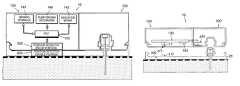
- FIGS. 1 a - billustrate a device having a patch unit ( 10 ) capable of dispensing and/or sensing (hereinafter referred to generally as “patch” or “patch unit”) and a remote control unit ( 40 ).
- the patch unit ( 10 )can include a single part ( FIG. 1 a ) or two parts ( FIG. 1 b ), e.g., reusable part ( 100 ) and disposable part ( 200 ).
- fluid deliverycan be programmed solely by the remote control unit ( 40 ) and/or by manual buttons (not shown) which could be provided on the patch unit ( 10 ).
- An embodiment of this arrangementis disclosed in our co-owned International Patent Application No. PCT/IL08/001,001, filed Jul. 20, 2008, claiming priority to U.S. Provisional Patent Application No. 60/961,527, filed Jul. 20, 2007, and titled “Manually Operable Portable Infusion Device”, the disclosures of which are incorporated herein by reference in their entireties.
- FIGS. 2 a - billustrate another embodiment of the device having a patch unit ( 10 ) provided with operating buttons ( 12 ) (e.g., keypad) and a display ( 14 ).
- operating buttons ( 12 )e.g., keypad
- fluid delivery programmingcan be carried out by the operating buttons ( 12 ).
- the devicecan include also a remote control unit.
- the patch unit ( 10 )can include a single part ( FIG. 2 a ) or two parts ( FIG. 2 b ), e.g., reusable part ( 100 ) and disposable part ( 200 ).
- the operating buttons ( 12 ) and the display ( 14 )can be located on the reusable part ( 100 ).
- An embodiment of this arrangementis disclosed in a co-owned, International Patent Application No.
- PCT/IL08/001,057entitled “Portable Infusion Device with Means for Monitoring and Controlling Fluid Delivery”, filed on Jul. 31, 2008, claiming priority to U.S. Provisional Patent Applications No. 60/963,148, filed Aug. 1, 2007, and No. 61/004,019, filed Nov. 21, 2007, both entitled “Portable Infusion Device with Means for Monitoring and Controlling Fluid Delivery”, the disclosures of which are incorporated herein by reference in their entireties.
- the devicecan include a cradle unit ( 20 ) that can be adhered to the skin of the patient, so that the patch unit ( 10 ) can be connected to and/or disconnected from the cradle unit ( 20 ) as desired.
- a cradle unit ( 20 )that can be adhered to the skin of the patient, so that the patch unit ( 10 ) can be connected to and/or disconnected from the cradle unit ( 20 ) as desired.
- An embodiment of the device employing the cradle unitis disclosed in co-owned U.S. patent application Ser. No. 12/004,837, and International Patent Application No. PCT/IL07/001,578, both filed Dec. 20, 2007, and both claiming priority to U.S. Provisional Patent Application No. 60/876,679, filed Dec. 22, 2006, the disclosures of which are incorporated herein by reference in their entireties.
- FIGS. 3 a - billustrate side and upper views (respectively) of an exemplary cradle unit ( 20 ).
- the cradle unit ( 20 )can include the following elements:
- FIG. 3 cillustrates an exemplary embodiment of the cradle unit ( 20 ) having a cradle base ( 300 ) with anchoring latches ( 302 , 304 ) and a well ( 310 ).
- a cannula(not shown) can be inserted into the subcutaneous compartment of the patient's body through the well ( 310 ) of the cradle unit ( 20 ).
- the insertion of the cannula into the subcutaneous compartmentcan be carried out by a dedicated inserter (not shown), e.g., an embodiment of which is disclosed in a co-owned International Patent Application No.
- FIG. 4 aillustrates the cradle unit ( 20 ) being adhered to the patient's skin ( 5 ).
- FIG. 4 billustrates an exemplary connection of the patch unit ( 10 ) to the adhered cradle unit ( 20 ) (after cannula insertion).
- FIG. 4 cillustrates the patch unit ( 10 ) being connected to the cradle unit ( 20 ) and ready for operation.
- FIG. 4 dillustrate the patch unit ( 10 ) being disconnected from the cradle unit ( 20 ).
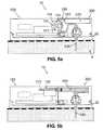
- FIGS. 5 a - dillustrate exemplary patch units that are configured to be attached to the cradle unit ( 20 ).
- FIG. 5 aillustrates an exemplary fluid delivery device having a cradle unit ( 20 ) and a two-part dispensing patch unit ( 10 ) that employs a peristaltic pumping mechanism. Rotation of a rotary wheel ( 110 ) and pressing of rollers ( 101 ) against a delivery tube ( 230 ) periodically positively displaces fluid from a reservoir ( 220 ) into the delivery tube ( 230 ) by virtue of a peristaltic motion. The fluid is then delivered via a cannula ( 330 ) into the subcutaneous compartment ( 4 ) within the patient's body.
- FIG. 5 billustrates an exemplary fluid delivery device having a cradle unit ( 20 ) and a two-part dispensing patch unit ( 10 ), which employs instead of a peristaltic pumping mechanism a syringe-type pumping mechanism.
- a plunger ( 210 )is displaced within a reservoir ( 220 ) and forces fluid towards the cannula ( 330 ).
- FIG. 5 cillustrates an exemplary analyte sensing device having a two-part sensing patch unit ( 10 ) and a cradle unit ( 20 ).
- an optical sensor for analyte sensingcan be employed.
- One or more optical meanscan be used for creating an optical path between a light source ( 102 ) and a sample.
- the optical pathcan be located in the subcutaneous portion of the cannula ( 330 ).
- the optical pathterminates at a light detector ( 104 ).
- FIG. 5 dillustrates an exemplary dual function device having a cradle unit ( 20 ) and a patch unit ( 10 ) that can be configured to dispense therapeutic fluid (e.g., insulin) and sense analyte (e.g. glucose).
- therapeutic fluide.g., insulin
- analytee.g. glucose
- the dispensing and sensing functionscan be independent from one another, or as an alternative, the device may operate in a semi or fully closed-loop mode.
- An embodiment of this arrangementis disclosed in a co-pending, co-owned U.S. patent application Ser. No. 11/706,606, the disclosure of which is incorporated herein by reference in its entirety.
- a dedicated position detectorcan be provided within the device for detecting whether the patch unit is connected or disconnected.
- the position detectorcan be configured to generate a signal output, which can be received at the central processing unit (CPU).
- the position detector's signal outputcan correspond to the current position status of the patch unit, i.e., whether it is connected to the cradle unit or disconnected therefrom.
- the CPUcan assign the patch unit the appropriate position status.
- the position detectoraccording to some embodiments comprises two parts one of which being located on the patch unit (“patch portion”) and the other on the cradle unit (“cradle portion”). It should be borne in mind that according to other embodiments the position detector may comprise only a single part.
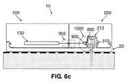
- FIGS. 6 a - cillustrate various locations of parts of a position detector ( 1000 ) on the cradle unit ( 20 ) and on the patch unit ( 10 ).
- FIG. 6 aillustrates an embodiment in which one part, namely a cradle portion ( 800 ), is located on the upper side of a cradle base ( 300 ) while the other part, namely a patch portion ( 900 ), is located on the bottom side of the patch unit ( 10 ).
- the patch portion ( 900 )can be located on the reusable part ( 100 ).
- the patch portion ( 900 )can be located on the disposable part ( 200 ) as well.
- FIG. 6 billustrates an exemplary embodiment in which the cradle portion ( 800 ) of the position detector ( 1000 ) is located on one of the cradle unit's anchoring latches (e.g., on the latch designated by numeral 302 ) and the patch portion ( 900 ) of the position detector ( 1000 ) is located in close proximity.
- FIG. 8 billustrates an exemplary embodiment in which the cradle portion ( 800 ) of the position detector ( 1000 ) is located on one of the cradle unit's anchoring latches (e.g., on the latch designated by numeral 302 ) and the patch portion ( 900 ) of the position detector ( 1000 ) is located in close proximity.
- FIG. 6 cillustrates an exemplary embodiment in which the cradle portion ( 800 ) of the position detector ( 1000 ) is located on the well ( 310 ) and the patch portion ( 900 ) of the position detector ( 1000 ) is located on the patch unit's outlet port ( 213 ).
- the outlet port ( 213 )could be located in the disposable part ( 200 ), and, thus, the patch portion ( 900 ) will be provided with dedicated means ( 902 ) (e.g. wires, metal tabs) for electrical connection to the PCB ( 130 ) located in the reusable part ( 100 ).
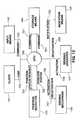
- FIG. 7illustrates exemplary components associated with the patch unit's position status setting and operation control.
- the CPU ( 140 )can assign the patch unit a “connected” or “disconnected” position status according to received output, and then control the operation of the pump driving mechanism ( 146 ) and/or sensing apparatus ( 147 ) according to the detected patch unit position status (e.g., deactivation of pump driving mechanism ( 146 ) and/or sensing apparatus ( 147 ) when the patch unit is disconnected from the cradle unit ( 20 )).
- the CPU ( 140 )can be configured to notify the user via an indication means ( 145 ) for indicating the current position status.
- FIGS. 8-12illustrate exemplary cross-sectional views of a two-part patch unit ( 10 ) and a cradle unit ( 40 ) employing various types of position detectors.
- the cradle portion of the position detectoris located on the upper side of the cradle base ( 300 ) and the patch portion of the position detector on the patch unit's ( 10 ) bottom side.
- both detector portionscan be located adjacently at any other location of patch and cradle units.
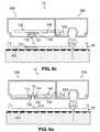
- FIGS. 8 a - cillustrate an embodiment of a position detector that can be configured to use optical sensing.
- the position detectorcan be configured to include a light emitting diode (LED) ( 112 ) and a light detector ( 114 ).
- the LED ( 112 ) and light detector ( 114 )are configured to be adjacent to the bottom side of the PCB ( 130 ) (e.g., the side of the PCB ( 130 ) that faces the cradle unit ( 20 )).
- the LED ( 112 ) and the light detector ( 114 )may be separately located items, as shown in FIGS. 8 a - b , or they may be fixed adjacent to each other being deployed on a common support frame ( 115 ), as shown in FIG.
- the LED ( 112 ) and the light detector ( 114 )can be configured to have leads (not shown), which can be soldered to the PCB ( 130 ), thereby establishing electrical connection.
- at least a portion ( 11 ) of the housing of the reusable part ( 100 ), which is located beneath, the LED ( 112 ) and the light detector ( 114 ),can be fabricated from a transparent material so that light could pass through it.
- the cradle base ( 300 )can be provided with a reflective surface ( 311 ), which is located opposite to the transparent portion ( 11 ) of the reusable part ( 100 ) housing.
- FIG. 8 aillustrates exemplary patch unit ( 10 ) and cradle unit ( 20 ), when they are not connected. In this case the light emitted by the LED ( 112 ) passes through the transparent portion ( 11 ) of the reusable part's housing and it is not sensed by the light detector ( 114 ).
- FIG. 8 billustrates exemplary patch unit ( 10 ) being connected to the cradle unit ( 20 ).
- the light emitted by the LED ( 112 )passes through the transparent portion ( 11 ) of the reusable part ( 100 ) housing, is reflected by the reflective surface ( 311 ) of the cradle unit ( 20 ), and is then sensed by the light detector ( 114 ).
- the cradle unit ( 20 )is transparent, the patient's skin may act as a reflective surface, in which case the transparent configuration of the cradle unit can act as the cradle unit portion of the position detector.
- the cradle unit ( 20 )can be fabricated entirely from a reflective material, or it can be painted in a bright color. In these cases, the reflective qualities of the cradle unit can represent the cradle portion of the position detector.
- the CPU ( 140 )is configured to receive “yes”/“no” light detection signals, set the patch unit's position status to “connected” or “disconnected” based on the received signal, and control the patch unit's operation accordingly.
- the LED ( 112 )can be configured to emit light continuously, periodically (e.g. every 1 sec for a period of 1 ⁇ sec), or in any other fashion. This can be done to save energy supplied by at least one battery ( 240 ) located in the disposable part ( 200 ) or in the reusable part ( 100 ).
- FIGS. 9 a - billustrate another exemplary embodiment of the position detector the operation of which is based on optical sensing, according to the present invention.
- the bottom side of the reusable part's ( 100 ) housingis configured to have a depression ( 13 ). At least two walls ( 132 , 134 ) of the depression ( 13 ) can be fabricated from a transparent material so that light could pass through them.
- the PCB ( 130 ) in this embodimentis configured such that a LED ( 112 ) and a light detector ( 114 ) can be soldered to the PCB ( 130 ) and be situated on opposite sides of the depression ( 13 ) thus facing each other.
- the cradle base ( 300 )is provided with a protrusion ( 313 ) configured to fit inside the depression ( 13 ) provided in reusable part's ( 100 ) housing.
- FIG. 9 aillustrates the patch unit ( 10 ) and the cradle unit ( 20 ) when they are not connected. In this case, the light emitted by the LED ( 112 ) passes through the transparent walls ( 132 , 134 ) of the depression ( 13 ) in the reusable part's ( 100 ) housing and is collected by the light detector ( 114 ).
- FIG. 9 bshows the patch unit ( 10 ) connected to the cradle unit ( 20 ).
- the cradle base's protrusion ( 313 )is located inside the depression ( 13 ) in the reusable part's ( 100 ) housing, thus preventing light from passing from the LED ( 112 ) to the light detector ( 114 ).
- the light emitted by the LED ( 112 )is either absorbed by the protrusion ( 313 ) or it is reflected by it, depending on the material it is fabricated from and its color, but in either case no light is collected by the light detector ( 114 ).
- the CPU(not shown) is configured to receive “yes”/“no” light detection signals and accordingly set the patch status to “disconnected” or “connected”.
- FIGS. 10 a - billustrate another exemplary embodiment of the position detector, according to the present invention.
- the magnetic component ( 16 )can be any component that is affected by a magnetic field, for example, an electrical “ON/OFF” Reed switch or a Hall Effect sensor with varying voltage output.
- the signals generated by the magnetic componentare interpreted by the CPU ( 140 ) as “connected”/“disconnected” positions and the patch's operation is controlled by the CPU ( 145 ) accordingly.
- FIG. 10 aillustrates the patch unit ( 10 ) and the cradle unit ( 20 ) when they are not connected
- FIG. 10 billustrates the patch unit ( 10 ) connected to the cradle unit ( 20 ).
- FIGS. 11 a - billustrate an exemplary embodiment of an electro-mechanical position detector, according to the present invention.
- an electronic switch ( 17 )is provided, which can be a commercially available tactile switch (e.g., a tact switch manufactured by Alps Electric Co., Ltd., Japan), or any other electronic switch.
- the switchcan be attached to the PCB ( 130 ) and connected to the CPU ( 140 ).
- a portion ( 117 ) of the reusable part ( 100 ) housing, which is located directly beneath the electronic switch ( 17 ),may be fabricated from a resilient material, e.g. rubber, preferably using a dedicated molding process so that the patch unit ( 10 ) remains water-tight.
- 11 billustrate the patch ( 10 ) and cradle ( 20 ) units in “disconnected” and “connected” positions respectively.
- a protrusion ( 317 )which is provided in the cradle base ( 300 ) pushes the resilient portion ( 117 ) of the reusable part ( 100 ) housing against the electronic switch ( 17 ) and turns it in ON or OFF state (depending whether the switch is normally closed or normally open).
- the state of the electronic switch ( 17 )(ON or OFF) is interpreted by the CPU as “connected”/“disconnected” patch unit position.
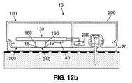
- FIGS. 12 a - billustrate another exemplary embodiment of the position detector, which can operate as an electronic switch, according to the present invention.
- two electrically conductive surfacese.g. fabricated from gold or nickel
- the conductive surfaces ( 18 , 19 )are either embedded in the bottom side of the housing of the reusable part ( 100 ), or they are secured thereon by any other suitable method.
- the conductive surfaces ( 18 , 19 )can be configured to be electrically connected to the PCB ( 130 ) by appropriate wires ( 180 , 190 ).
- a third conductive surface ( 318 )can be either embedded in the cradle base ( 300 ) or protruding from the cradle base ( 300 ).
- the area of the third conductive surface ( 318 )can be configured to be large enough to ensure that it contacts both conductive surfaces ( 18 , 19 ) upon connection of the patch unit ( 10 ) and the cradle unit ( 20 ).
- the three conductive surfaces ( 18 , 19 and 318 )together constitute an electronic switch.
- FIG. 12 aillustrates the patch unit ( 10 ) and the cradle unit ( 20 ) when they are not connected. The switch in this case is in an “OFF” state, thus the CPU assigns the patch unit ( 10 ) a “disconnected” status.
- FIG. 12 aillustrates the patch unit ( 10 ) and the cradle unit ( 20 ) when they are not connected. The switch in this case is in an “OFF” state, thus the CPU assigns the patch unit ( 10 ) a “disconnected
- FIG. 12 billustrates the patch unit ( 10 ) connected to the cradle unit ( 20 ).
- electrical contactis established between the conductive surfaces ( 18 , 19 ) and the conductive surface ( 318 ), thus the switch is in an “ON” state, and the CPU assigns the patch unit ( 10 ) a “connected” status.
- the switchmay alternatively be set up such that establishing contact between the reusable part's conductive surfaces ( 18 , 19 ) and the cradle base's conductive surface ( 318 ), would place the switch in an “OFF” state.
- the CPUwill assign the patch unit ( 10 ) a “connected” status when the switch is in an “OFF” state and a “disconnected” status when the switch is in an “ON” state.
- a proximity sensore.g. an inductive proximity sensor
- the sensoris attached to the PCB, and the cradle base can be provided with a surface fabricated from a magnetic material (e.g., ferromagnetic material), which could be either embedded in the cradle base or protruding from it.
- the sensorcan use a coil or an inductor as a transducer to produce a magnetic field.
- the patch unitis in close proximity to the cradle unit, the magnetic surface would be exposed to the sensor's magnetic field. Electrical currents (i.e., Eddy currents) would then build up in the magnetic surface and dampen the sensor's magnetic field.
- An output thresholdcan be preprogrammed such that the CPU will set the patch unit's status to “connected” only when the distance between the sensor and the magnetic surface is at its minimum corresponding to a situation when the patch unit is connected to the cradle unit.
- FIG. 13is a flow chart illustrating exemplary method for setting and controlling operation of the patch unit.
- Position indication ( 702 )is provided by the position detector ( 143 ).
- Position indication ( 702 )can be generated, for example, upon request ( 704 ) of the CPU ( 140 ), or automatically when the patch unit is being connected/disconnected, or periodically according to a predetermined time schedule. As can be understood by one skilled in the art, other ways of generating position indication signals are possible.
- Some stepsmay be carried out automatically when the patch unit's position is changed. Such steps may include, for example, deactivation or activation ( 706 , 707 ) of the patch unit's driving mechanism ( 146 ) and deactivation or activation of one or more sensing apparatuses ( 147 ), as will be demonstrated below.
- the sensing apparatus ( 147 )can be, for example, a sensor for detecting occlusion in the fluid delivery tube, as described in co-pending, co-owned U.S. patent application Ser. No. 11/810,854 and co-owned International Patent Application No. PCT/IL07/000,684, both filed Jun. 6, 2007, disclosures of which are incorporated herein by reference in their entireties.
- sensing apparatusesmay include a sensor for monitoring analyte (e.g., glucose) concentration levels in the patient's body, as disclosed, for example, in co-pending, co-owned U.S. patent application Ser. No. 11/706,606, filed Feb. 14, 2007, disclosure of which is incorporated herein by reference in its entirety.
- analytee.g., glucose
- a notificationmay be sent to the user via an indication means ( 145 ) (e.g. buzzer, visual display) upon position status change and upon activation/deactivation of a patch unit component based on a position status change.
- the current position(designated by numeral 702 ′ in FIG. 14 a ) may also be checked after a command ( 701 ) has been generated by a user by an input means ( 142 ) (e.g. remote control unit or operating buttons provided on the patch unit) and received at the CPU ( 140 ). If there is a mismatch between a command ( 701 ) and the patch position status (hereinafter “inexecutable command”) (e.g.
- a bolus delivery commandis generated when the patch unit and cradle unit are not connected), the command ( 701 ) is stored in the storage means ( 144 ).
- the stored command ( 701 ′)may include additional data, such as command timing ( 703 ) provided by a clock ( 141 ).
- FIG. 14 ais a flow chart of an exemplary process ( 730 ) that takes place after command ( 701 ) is received by the CPU.
- the command ( 701 )is checked (as shown in step 732 ) in accordance to a current patch position. If the command can be executed, then the execution can be immediately performed (as shown in step 733 ). If the command cannot be executed, then it can be stored (as shown in step 734 ) for a later execution. The user can be notified accordingly, as shown in step 735 . For example, a bolus delivery command can be received while the patch unit's current status ( 702 ′) is “disconnected”. The command cannot be executed and thus it is stored for a later execution, i.e., upon reconnection of the patch unit to the cradle unit. Appropriate notification can be sent to the patient.
- Some inexecutable commandsare not stored for later execution but they are cancelled once they are determined “inexecutable”, e.g., a periodical command to sample the occlusion sensor.
- FIG. 14 bis a flow chart of an exemplary process ( 750 ) taking place after receiving position indication ( 702 ) from the patch portion of the position indicator ( 143 ). If there is a mismatch (as shown in step 751 ) between the received position ( 702 ) and the current position ( 702 ′), the following exemplary steps can be carried out in any suitable order:
- Step 752update current position ( 702 ′);
- Step 753activate or deactivate patch components based on the current position ( 702 ′);
- Step 754store relevant data (e.g., position change timing);
- Step 755process and execute previously stored commands ( 701 ′) (e.g., using process 730 ) according to patch position.
- the driving mechanismcan be deactivated, and timing and amount of undelivered volume can be recorded.
- the patch unitis provided with operating buttons and a display, the operating buttons may be unlocked and the display may be activated upon disconnection. After reconnection the patch position can be set to “connected” status, timing is recorded, fluid delivery is resumed, the operating buttons may become locked, and the display may be deactivated.
- FIG. 14 cis a flow chart of an exemplary process ( 760 ) for position checking after every command ( 701 ) is received.
- the following exemplary stepscan be performed by process ( 760 ) in any suitable order:
- Step 761send a position status request ( 704 ) from the CPU to the position detector, and receive position status indication ( 702 );
- Step 762check command ( 701 ) in accordance with received patch position status ( 702 ),
- Step 763execute the command if it is executable
- Step 764store the command if it is inexecutable
- Step 765notify the patient.
- a bolus delivery command generated by the usercan be received at the CPU, and a “disconnected” position status indication ( 702 ) can be generated by the position detector.
- the commandcannot be executed, it is therefore stored for later execution, and notification (as shown in step 765 ) can be sent to the patient.
- Some inexecutable commandsare not stored for a later execution but they are cancelled once they are determined “inexecutable”, e.g., a periodical command to sample the occlusion sensor.
- various position detectorscan allow the user to safely disconnect and reconnect the patch unit from and to the cradle unit without using the remote control for suspension or resumption of patch operation, because these actions can be done automatically upon disconnection/reconnection of the patch unit to the cradle unit.
- the position detectorcan also prevent the patch unit from operating in case of unintentional disconnection.
- a co-owned International Patent Application No. PCT/IL08/001,001, filed Jul. 20, 2008, claiming priority to U.S. Provisional Patent Application No. 60/961,527, filed Jul. 20, 2007, and titled “Manually Operable Portable Infusion Pump”discloses a patch unit having manual button(s) allowing the user to initiate bolus delivery without using the remote control unit.
- a dedicated position detector for detecting whether the patch unit is connected to or disconnected from the cradle unitcan be used.
- a method for controlling the patch unit's operation accordinglycan be implemented.
- One of the advantages of using some implementations of the detectorcan be that the user can press the bolus button(s) in a situation when the patch unit is disconnected from the cradle unit and bolus delivery will commence only after the patch unit has been reconnected to the cradle unit.
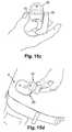
- FIGS. 15 a - dillustrate an exemplary two-part patch unit ( 10 ) provided with manual buttons ( 15 ) and with a position detector (not shown in the Figures).
- FIG. 15 aillustrates an exemplary patch unit ( 10 ) connected to a cradle unit ( 20 ).
- FIG. 15 billustrates the patch unit ( 10 ) being disconnected from the cradle unit ( 20 ).
- FIG. 15 cillustrates the user simultaneously pressing two bolus buttons ( 15 ).
- FIG. 15 dillustrates the patch unit ( 10 ) being reconnected to the cradle unit ( 20 ).
- 15 eillustrates an exemplary embodiment of a two-part patch unit ( 10 ) provided with manual bolus buttons ( 15 ) and a display ( 50 ) on the reusable part's ( 100 ) housing.
- the patch unit ( 10 )includes a single part, the display ( 50 ) can be positioned anywhere on the patch unit's housing.
- the display ( 50 )can be configured to show a programmed bolus dosage.
- the display ( 50 )can be configured to show additional data, such as the amount of fluid left in the reservoir, the battery status, etc.
- bolus deliverywill not commence until the patch unit ( 10 ) is reconnected to the cradle unit ( 20 ).
- the usercan therefore attach the cradle unit ( 20 ), and consequently the patch unit ( 10 ), to the body at remote locations, e.g. the back or buttocks, and still be able to look at the display ( 50 ) while pressing the bolus buttons.
- FIGS. 16 a - dillustrate an exemplary two-part patch unit ( 10 ) provided with operating buttons (the buttons are designated as a group by numeral 12 ), a display ( 14 ) and a position detector (not seen).
- the usercan disconnect the patch unit ( 10 ) from the cradle unit ( 20 ), issue the necessary fluid delivery and/or sensing commands using the operating buttons ( 12 ) and the display ( 14 ), and then reconnect the patch unit ( 10 ).
- the programmed commandscan be executed only after the patch unit ( 10 ) is reconnected to the cradle unit ( 20 ).
- implementations of the subject matter described hereinmay be realized in digital electronic circuitry, integrated circuitry, specially designed ASICs (application specific integrated circuits), computer hardware, firmware, software, and/or combinations thereof.
- ASICsapplication specific integrated circuits
- These various implementationsmay include implementation in one or more computer programs that are executable and/or interpretable on a programmable system including at least one programmable processor, which may be special or general purpose, coupled to receive data and instructions from, and to transmit data and instructions to, a storage system, at least one input device, and at least one output device.
- the subject matter described hereinmay be implemented on a computer having a display device (e.g., a CRT (cathode ray tube) or LCD (liquid crystal display) monitor) for displaying information to the user and a keyboard and a pointing device (e.g., a mouse or a trackball) by which the user may provide input to the computer.
- a display devicee.g., a CRT (cathode ray tube) or LCD (liquid crystal display) monitor
- a keyboard and a pointing devicee.g., a mouse or a trackball
- Other kinds of devicesmay be used to provide for interaction with a user as well; for example, feedback provided to the user may be any form of sensory feedback (e.g., visual feedback, auditory feedback, or tactile feedback); and input from the user may be received in any form, including acoustic, speech, or tactile input.
- the subject matter described hereinmay be implemented in a computing system that includes a back-end component (e.g., as a data server), or that includes a middleware component (e.g., an application server), or that includes a front-end component (e.g., a client computer having a graphical user interface or a Web browser through which a user may interact with an implementation of the subject matter described herein), or any combination of such back-end, middleware, or front-end components.
- the components of the systemmay be interconnected by any form or medium of digital data communication (e.g., a communication network). Examples of communication networks include a local area network (“LAN”), a wide area network (“WAN”), and the Internet.
- LANlocal area network
- WANwide area network
- the Internetthe global information network
- the computing systemmay include clients and servers.
- a client and serverare generally remote from each other and typically interact through a communication network.
- the relationship of client and serverarises by virtue of computer programs running on the respective computers and having a client-server relationship to each other.
Landscapes
- Health & Medical Sciences (AREA)
- Dermatology (AREA)
- Vascular Medicine (AREA)
- Engineering & Computer Science (AREA)
- Anesthesiology (AREA)
- Biomedical Technology (AREA)
- Heart & Thoracic Surgery (AREA)
- Hematology (AREA)
- Life Sciences & Earth Sciences (AREA)
- Animal Behavior & Ethology (AREA)
- General Health & Medical Sciences (AREA)
- Public Health (AREA)
- Veterinary Medicine (AREA)
- Infusion, Injection, And Reservoir Apparatuses (AREA)
- Measurement Of The Respiration, Hearing Ability, Form, And Blood Characteristics Of Living Organisms (AREA)
Abstract
Description
- 1) Cradle unit is adhered to the skin;
- 2) Cannula is inserted through a cradle unit passageway (also referred to as a “well”) into the subcutaneous tissue. The cannula, including a rubber septum, can be connected to the cradle unit's “well”;
- 3) The patch unit is connected to the cradle unit. The connecting lumen pierces a rubber septum allowing fluid communication between the reservoir, cannula and the body.
- A patch unit, which can be remotely controlled or manually controlled by operating buttons. In some embodiments, the patch unit can include two parts: reusable and disposable. The disposable part can be configured to include a reservoir and an outlet port with a connecting lumen. The reusable part can be configured to include electronics and at least a portion of a dispensing mechanism.
- A cradle unit, which can be adherable to the patient's skin, e.g., by an adhesive.
- Cradle base (300)—configured as a flat sheet with an adhesive layer facing the skin (5) and with anchoring latches (302,304) on its upper side for connection and disconnection of the patch unit.
- Well (310)—configured as a tubular protrusion emerging upwardly from the cradle base (300) to allow alignment with and appropriate connection of the patch unit. The well (310) constitutes a passageway through which a cannula (not shown) can be inserted into the patient's body for fluid (e.g. insulin) delivery and/or for analyte (e.g. glucose) sensing. The cradle unit (20) can be configured to have more than one “well”. For example, in case when two cannulae are employed, one for fluid delivery and the other for analyte sensing.
Claims (22)
Priority Applications (1)
| Application Number | Priority Date | Filing Date | Title |
|---|---|---|---|
| US12/452,926US8147446B2 (en) | 2007-08-01 | 2008-07-31 | Detachable portable infusion device |
Applications Claiming Priority (4)
| Application Number | Priority Date | Filing Date | Title |
|---|---|---|---|
| US96304507P | 2007-08-01 | 2007-08-01 | |
| US99965407P | 2007-10-19 | 2007-10-19 | |
| US12/452,926US8147446B2 (en) | 2007-08-01 | 2008-07-31 | Detachable portable infusion device |
| PCT/IL2008/001056WO2009016635A2 (en) | 2007-08-01 | 2008-07-31 | Detachable portable infusion device |
Related Parent Applications (1)
| Application Number | Title | Priority Date | Filing Date |
|---|---|---|---|
| PCT/IL2008/001056A-371-Of-InternationalWO2009016635A2 (en) | 2007-08-01 | 2008-07-31 | Detachable portable infusion device |
Related Child Applications (1)
| Application Number | Title | Priority Date | Filing Date |
|---|---|---|---|
| US13/419,182DivisionUS8747348B2 (en) | 2007-08-01 | 2012-03-13 | Detachable portable infusion device |
Publications (2)
| Publication Number | Publication Date |
|---|---|
| US20100137790A1 US20100137790A1 (en) | 2010-06-03 |
| US8147446B2true US8147446B2 (en) | 2012-04-03 |
Family
ID=40090702
Family Applications (2)
| Application Number | Title | Priority Date | Filing Date |
|---|---|---|---|
| US12/452,926ActiveUS8147446B2 (en) | 2007-08-01 | 2008-07-31 | Detachable portable infusion device |
| US13/419,182ActiveUS8747348B2 (en) | 2007-08-01 | 2012-03-13 | Detachable portable infusion device |
Family Applications After (1)
| Application Number | Title | Priority Date | Filing Date |
|---|---|---|---|
| US13/419,182ActiveUS8747348B2 (en) | 2007-08-01 | 2012-03-13 | Detachable portable infusion device |
Country Status (4)
| Country | Link |
|---|---|
| US (2) | US8147446B2 (en) |
| EP (1) | EP2185218B1 (en) |
| DK (1) | DK2185218T3 (en) |
| WO (1) | WO2009016635A2 (en) |
Cited By (59)
| Publication number | Priority date | Publication date | Assignee | Title |
|---|---|---|---|---|
| US20110160697A1 (en)* | 2008-08-28 | 2011-06-30 | Medingo Ltd. | Device and method for enhanced subcutaneous insulin absorption |
| US20120232518A1 (en)* | 2007-08-01 | 2012-09-13 | Medingo, Ltd. | Detachable portable infusion device |
| US9072827B2 (en) | 2012-03-26 | 2015-07-07 | Medimop Medical Projects Ltd. | Fail safe point protector for needle safety flap |
| US9149575B2 (en) | 2010-01-19 | 2015-10-06 | Medimop Medical Projects Ltd. | Needle assembly for drug pump |
| US20150292856A1 (en)* | 2014-04-09 | 2015-10-15 | Qualcomm Incorporated | Method, devices and systems for detecting an attachment of an electronic patch |
| US9166313B2 (en) | 2013-04-30 | 2015-10-20 | Medimop Medical Projects | Power supply contact for installation of printed circuit board |
| US9173997B2 (en) | 2007-10-02 | 2015-11-03 | Medimop Medical Projects Ltd. | External drug pump |
| USD747799S1 (en) | 2011-03-22 | 2016-01-19 | Medimop Medical Projects Ltd. | Cartridge |
| US9259532B2 (en) | 2010-01-19 | 2016-02-16 | Medimop Medical Projects Ltd. | Cartridge interface assembly |
| US9345836B2 (en) | 2007-10-02 | 2016-05-24 | Medimop Medical Projects Ltd. | Disengagement resistant telescoping assembly and unidirectional method of assembly for such |
| US9421323B2 (en) | 2013-01-03 | 2016-08-23 | Medimop Medical Projects Ltd. | Door and doorstop for portable one use drug delivery apparatus |
| US9452261B2 (en) | 2010-05-10 | 2016-09-27 | Medimop Medical Projects Ltd. | Low volume accurate injector |
| US9463280B2 (en) | 2012-03-26 | 2016-10-11 | Medimop Medical Projects Ltd. | Motion activated septum puncturing drug delivery device |
| US9572926B2 (en) | 2009-09-15 | 2017-02-21 | Medimop Medical Projects Ltd. | Cartridge insertion assembly |
| US9656019B2 (en) | 2007-10-02 | 2017-05-23 | Medimop Medical Projects Ltd. | Apparatuses for securing components of a drug delivery system during transport and methods of using same |
| US9669160B2 (en) | 2014-07-30 | 2017-06-06 | Tandem Diabetes Care, Inc. | Temporary suspension for closed-loop medicament therapy |
| US9744297B2 (en) | 2015-04-10 | 2017-08-29 | Medimop Medical Projects Ltd. | Needle cannula position as an input to operational control of an injection device |
| CN107106762A (en)* | 2015-02-23 | 2017-08-29 | 泰尔茂株式会社 | drug delivery device |
| US9795534B2 (en) | 2015-03-04 | 2017-10-24 | Medimop Medical Projects Ltd. | Compliant coupling assembly for cartridge coupling of a drug delivery device |
| US9833191B2 (en) | 2012-11-07 | 2017-12-05 | Bigfoot Biomedical, Inc. | Computer-based diabetes management |
| US9833177B2 (en) | 2007-05-30 | 2017-12-05 | Tandem Diabetes Care, Inc. | Insulin pump based expert system |
| US20180014787A1 (en)* | 2016-07-13 | 2018-01-18 | Qualcomm Incorporated | Methods, systems, and apparatuses for detecting activation of an electronic device |
| US9889256B2 (en) | 2013-05-03 | 2018-02-13 | Medimop Medical Projects Ltd. | Sensing a status of an infuser based on sensing motor control and power input |
| US9987432B2 (en) | 2015-09-22 | 2018-06-05 | West Pharma. Services IL, Ltd. | Rotation resistant friction adapter for plunger driver of drug delivery device |
| US10016559B2 (en) | 2009-12-04 | 2018-07-10 | Smiths Medical Asd, Inc. | Advanced step therapy delivery for an ambulatory infusion pump and system |
| US10016561B2 (en) | 2013-03-15 | 2018-07-10 | Tandem Diabetes Care, Inc. | Clinical variable determination |
| US10052049B2 (en) | 2008-01-07 | 2018-08-21 | Tandem Diabetes Care, Inc. | Infusion pump with blood glucose alert delay |
| US10071198B2 (en) | 2012-11-02 | 2018-09-11 | West Pharma. Servicees IL, Ltd. | Adhesive structure for medical device |
| US10071196B2 (en) | 2012-05-15 | 2018-09-11 | West Pharma. Services IL, Ltd. | Method for selectively powering a battery-operated drug-delivery device and device therefor |
| US10149943B2 (en) | 2015-05-29 | 2018-12-11 | West Pharma. Services IL, Ltd. | Linear rotation stabilizer for a telescoping syringe stopper driverdriving assembly |
| US10188793B2 (en) | 2014-06-10 | 2019-01-29 | Bigfoot Biomedical, Inc. | Insulin on board calculation, schedule and delivery |
| US20190059757A1 (en)* | 2017-08-31 | 2019-02-28 | Medicomp, Inc. | Pendant physiological signal monitor and associated systems and methods |
| US10251813B2 (en) | 2015-03-04 | 2019-04-09 | West Pharma. Services IL, Ltd. | Flexibly mounted cartridge alignment collar for drug delivery device |
| US10293120B2 (en) | 2015-04-10 | 2019-05-21 | West Pharma. Services IL, Ltd. | Redundant injection device status indication |
| US10335545B2 (en) | 2012-01-31 | 2019-07-02 | West Pharma. Services IL, Ltd. | Time dependent drug delivery apparatus |
| USD853583S1 (en) | 2017-03-29 | 2019-07-09 | Becton, Dickinson And Company | Hand-held device housing |
| US10357606B2 (en) | 2013-03-13 | 2019-07-23 | Tandem Diabetes Care, Inc. | System and method for integration of insulin pumps and continuous glucose monitoring |
| US10357607B2 (en) | 2007-05-24 | 2019-07-23 | Tandem Diabetes Care, Inc. | Correction factor testing using frequent blood glucose input |
| US10420880B2 (en) | 2007-10-02 | 2019-09-24 | West Pharma. Services IL, Ltd. | Key for securing components of a drug delivery system during assembly and/or transport and methods of using same |
| US10430043B2 (en) | 2012-06-07 | 2019-10-01 | Tandem Diabetes Care, Inc. | Preventing inadvertent changes in ambulatory medical devices |
| US10569016B2 (en) | 2015-12-29 | 2020-02-25 | Tandem Diabetes Care, Inc. | System and method for switching between closed loop and open loop control of an ambulatory infusion pump |
| US10668213B2 (en) | 2012-03-26 | 2020-06-02 | West Pharma. Services IL, Ltd. | Motion activated mechanisms for a drug delivery device |
| US11167086B2 (en) | 2008-09-15 | 2021-11-09 | West Pharma. Services IL, Ltd. | Stabilized pen injector |
| US11291763B2 (en) | 2007-03-13 | 2022-04-05 | Tandem Diabetes Care, Inc. | Basal rate testing using frequent blood glucose input |
| US11311674B2 (en) | 2016-01-21 | 2022-04-26 | West Pharma. Services IL, Ltd. | Medicament delivery device comprising a visual indicator |
| US11318254B2 (en) | 2015-10-09 | 2022-05-03 | West Pharma. Services IL, Ltd. | Injector needle cap remover |
| US11338090B2 (en) | 2016-08-01 | 2022-05-24 | West Pharma. Services IL, Ltd. | Anti-rotation cartridge pin |
| US11364337B2 (en) | 2016-01-21 | 2022-06-21 | West Pharma. Services IL, Ltd. | Force containment in an automatic injector |
| US11389597B2 (en) | 2016-03-16 | 2022-07-19 | West Pharma. Services IL, Ltd. | Staged telescopic screw assembly having different visual indicators |
| US11547802B2 (en) | 2015-10-09 | 2023-01-10 | West Pharma. Services IL, Ltd. | Angled syringe patch injector |
| US11676694B2 (en) | 2012-06-07 | 2023-06-13 | Tandem Diabetes Care, Inc. | Device and method for training users of ambulatory medical devices |
| US11672904B2 (en) | 2016-01-21 | 2023-06-13 | West Pharma. Services IL, Ltd. | Needle insertion and retraction mechanism |
| US11694794B2 (en) | 2012-04-23 | 2023-07-04 | Tandem Diabetes Care, Inc. | System and method for reduction of inadvertent activation of medical device during manipulation |
| US11730892B2 (en) | 2016-08-01 | 2023-08-22 | West Pharma. Services IL, Ltd. | Partial door closure prevention spring |
| US11819673B2 (en) | 2016-06-02 | 2023-11-21 | West Pharma. Services, IL, Ltd. | Three position needle retraction |
| US11819666B2 (en) | 2017-05-30 | 2023-11-21 | West Pharma. Services IL, Ltd. | Modular drive train for wearable injector |
| US11857767B2 (en) | 2017-12-22 | 2024-01-02 | West Pharma. Services IL, Ltd. | Injector usable with different dimension cartridges |
| US11931552B2 (en) | 2015-06-04 | 2024-03-19 | West Pharma Services Il, Ltd. | Cartridge insertion for drug delivery device |
| US12097357B2 (en) | 2008-09-15 | 2024-09-24 | West Pharma. Services IL, Ltd. | Stabilized pen injector |
Families Citing this family (89)
| Publication number | Priority date | Publication date | Assignee | Title |
|---|---|---|---|---|
| US8034026B2 (en) | 2001-05-18 | 2011-10-11 | Deka Products Limited Partnership | Infusion pump assembly |
| EP1815879A3 (en) | 2001-05-18 | 2007-11-14 | Deka Products Limited Partnership | Infusion set for a fluid pump |
| US8252321B2 (en) | 2004-09-13 | 2012-08-28 | Chrono Therapeutics, Inc. | Biosynchronous transdermal drug delivery for longevity, anti-aging, fatigue management, obesity, weight loss, weight management, delivery of nutraceuticals, and the treatment of hyperglycemia, alzheimer's disease, sleep disorders, parkinson's disease, aids, epilepsy, attention deficit disorder, nicotine addiction, cancer, headache and pain control, asthma, angina, hypertension, depression, cold, flu and the like |
| US9788771B2 (en) | 2006-10-23 | 2017-10-17 | Abbott Diabetes Care Inc. | Variable speed sensor insertion devices and methods of use |
| EP1762259B2 (en) | 2005-09-12 | 2025-01-01 | Unomedical A/S | Inserter for an infusion set with a first and second spring units |
| DK1962926T3 (en) | 2005-12-23 | 2009-09-28 | Unomedical As | injection device |
| WO2007098771A2 (en) | 2006-02-28 | 2007-09-07 | Unomedical A/S | Inserter for infusion part and infusion part provided with needle protector |
| CA2653631A1 (en) | 2006-06-07 | 2007-12-13 | Unomedical A/S | Inserter |
| CA2653764A1 (en) | 2006-06-09 | 2007-12-13 | Unomedical A/S | Mounting pad |
| JP2009545341A (en) | 2006-08-02 | 2009-12-24 | ウノメディカル アクティーゼルスカブ | Cannula and delivery device |
| WO2008080990A1 (en)* | 2006-12-29 | 2008-07-10 | Disetronic Licensing Ag | Infusion device that can be worn outside the body |
| EP2155311B1 (en) | 2007-06-20 | 2013-01-02 | Unomedical A/S | A method and an apparatus for making a catheter |
| AU2008270327A1 (en) | 2007-07-03 | 2009-01-08 | Unomedical A/S | Inserter having bistable equilibrium states |
| DE602008005153D1 (en) | 2007-07-10 | 2011-04-07 | Unomedical As | INSERT WITH TWO SPRINGS |
| AU2008281381A1 (en)* | 2007-08-01 | 2009-02-05 | F.Hoffmann-La Roche Ag | Portable infusion device provided with means for monitoring and controlling fluid delivery |
| ATE522240T1 (en) | 2008-02-13 | 2011-09-15 | Unomedical As | SEAL BETWEEN A CANNULAR PART AND A FLUID PATH |
| US9566384B2 (en) | 2008-02-20 | 2017-02-14 | Unomedical A/S | Insertion device with horizontally moving part |
| WO2009120692A2 (en)* | 2008-03-25 | 2009-10-01 | Animal Innovations, Inc. | Syringe mechanism for detecting syringe status |
| US8708376B2 (en) | 2008-10-10 | 2014-04-29 | Deka Products Limited Partnership | Medium connector |
| US9180245B2 (en) | 2008-10-10 | 2015-11-10 | Deka Products Limited Partnership | System and method for administering an infusible fluid |
| US8223028B2 (en) | 2008-10-10 | 2012-07-17 | Deka Products Limited Partnership | Occlusion detection system and method |
| US8262616B2 (en) | 2008-10-10 | 2012-09-11 | Deka Products Limited Partnership | Infusion pump assembly |
| US8016789B2 (en) | 2008-10-10 | 2011-09-13 | Deka Products Limited Partnership | Pump assembly with a removable cover assembly |
| US8267892B2 (en) | 2008-10-10 | 2012-09-18 | Deka Products Limited Partnership | Multi-language / multi-processor infusion pump assembly |
| US8066672B2 (en)* | 2008-10-10 | 2011-11-29 | Deka Products Limited Partnership | Infusion pump assembly with a backup power supply |
| AU2009331635A1 (en) | 2008-12-22 | 2011-06-23 | Unomedical A/S | Medical device comprising adhesive pad |
| WO2010072005A1 (en)* | 2008-12-24 | 2010-07-01 | Calasso, Irio, Giuseppe | System and methods for medicament infusion |
| AU2010277755A1 (en) | 2009-07-30 | 2012-02-02 | Unomedical A/S | Inserter device with horizontal moving part |
| KR20120047896A (en) | 2009-08-07 | 2012-05-14 | 우노메디컬 에이/에스 | Delivery device with sensor and one or more cannulas |
| US8932256B2 (en)* | 2009-09-02 | 2015-01-13 | Medtronic Minimed, Inc. | Insertion device systems and methods |
| US8900190B2 (en)* | 2009-09-02 | 2014-12-02 | Medtronic Minimed, Inc. | Insertion device systems and methods |
| US20110144587A1 (en)* | 2009-12-11 | 2011-06-16 | Stone Robert T | Liquid agent delivery apparatus, system and method |
| US8998858B2 (en)* | 2009-12-29 | 2015-04-07 | Medtronic Minimed, Inc. | Alignment and connection systems and methods |
| US8998840B2 (en) | 2009-12-30 | 2015-04-07 | Medtronic Minimed, Inc. | Connection and alignment systems and methods |
| US9039653B2 (en)* | 2009-12-29 | 2015-05-26 | Medtronic Minimed, Inc. | Retention systems and methods |
| US8435209B2 (en) | 2009-12-30 | 2013-05-07 | Medtronic Minimed, Inc. | Connection and alignment detection systems and methods |
| US11497850B2 (en) | 2009-12-30 | 2022-11-15 | Medtronic Minimed, Inc. | Connection and alignment detection systems and methods |
| US20120215163A1 (en) | 2009-12-30 | 2012-08-23 | Medtronic Minimed, Inc. | Sensing systems and methods |
| US8320961B2 (en)* | 2009-12-30 | 2012-11-27 | Nokia Corporation | Apparatus for a tangible interface |
| US9421321B2 (en) | 2009-12-30 | 2016-08-23 | Medtronic Minimed, Inc. | Connection and alignment systems and methods |
| KR20130018783A (en) | 2010-03-30 | 2013-02-25 | 우노메디컬 에이/에스 | Medical device |
| US9216249B2 (en) | 2010-09-24 | 2015-12-22 | Perqflo, Llc | Infusion pumps |
| US8915879B2 (en) | 2010-09-24 | 2014-12-23 | Perqflo, Llc | Infusion pumps |
| US9498573B2 (en) | 2010-09-24 | 2016-11-22 | Perqflo, Llc | Infusion pumps |
| US9381300B2 (en) | 2010-09-24 | 2016-07-05 | Perqflo, Llc | Infusion pumps |
| EP2433663A1 (en) | 2010-09-27 | 2012-03-28 | Unomedical A/S | Insertion system |
| EP2436412A1 (en) | 2010-10-04 | 2012-04-04 | Unomedical A/S | A sprinkler cannula |
| US8905972B2 (en) | 2010-11-20 | 2014-12-09 | Perqflo, Llc | Infusion pumps |
| US9808577B2 (en) | 2011-05-10 | 2017-11-07 | Insuline Medical Ltd. | Device, system and method for facilitating syringe based drug delivery and management thereof |
| EP2729148A4 (en) | 2011-07-06 | 2015-04-22 | Parkinson S Inst | COMPOSITIONS AND METHODS FOR TREATING SYMPTOMS IN PATIENTS WITH PARKINSON'S DISEASE |
| WO2013050277A1 (en) | 2011-10-05 | 2013-04-11 | Unomedical A/S | Inserter for simultaneous insertion of multiple transcutaneous parts |
| EP2583715A1 (en) | 2011-10-19 | 2013-04-24 | Unomedical A/S | Infusion tube system and method for manufacture |
| US9440051B2 (en) | 2011-10-27 | 2016-09-13 | Unomedical A/S | Inserter for a multiplicity of subcutaneous parts |
| HUE039650T2 (en) | 2012-01-17 | 2019-02-28 | Medirio Sa | System for medical treatment |
| CN204910157U (en) | 2012-03-05 | 2015-12-30 | 贝克顿·迪金森公司 | System for be used for at body liquid conveying |
| US20130310738A1 (en)* | 2012-05-21 | 2013-11-21 | Lifemedix, Llc | Portable intravenous fluid delivery device with a user interface |
| DE202012009560U1 (en)* | 2012-10-08 | 2014-01-09 | Oechsler Aktiengesellschaft | Event detector and medication donor with such event detector |
| US9522223B2 (en) | 2013-01-18 | 2016-12-20 | Medtronic Minimed, Inc. | Systems for fluid reservoir retention |
| US9107994B2 (en) | 2013-01-18 | 2015-08-18 | Medtronic Minimed, Inc. | Systems for fluid reservoir retention |
| US9033924B2 (en)* | 2013-01-18 | 2015-05-19 | Medtronic Minimed, Inc. | Systems for fluid reservoir retention |
| US10105487B2 (en) | 2013-01-24 | 2018-10-23 | Chrono Therapeutics Inc. | Optimized bio-synchronous bioactive agent delivery system |
| DK2865325T3 (en)* | 2013-10-23 | 2018-02-19 | Hoffmann La Roche | STANDING ON THE SKIN OF INFUSION PUMP OR CONTINUOUS BLOOD SUGAR MONITOR WITH OPTICAL INDICATION ORGANIZATION |
| US9452255B2 (en) | 2014-07-21 | 2016-09-27 | Medtronic Minimed, Inc. | Smart connection interface |
| US11464899B2 (en) | 2014-08-28 | 2022-10-11 | Becton, Dickinson And Company | Wireless communication for on-body medical devices |
| CN105311702B (en)* | 2014-09-03 | 2019-10-08 | 上海移宇科技股份有限公司 | Disposable duct free drug infusion system |
| US12178992B2 (en) | 2014-09-30 | 2024-12-31 | Medtronic Minimed, Inc. | Different disposable assemblies for the same reusable assembly |
| US10159786B2 (en) | 2014-09-30 | 2018-12-25 | Perqflo, Llc | Hybrid ambulatory infusion pumps |
| US20170216523A1 (en)* | 2014-10-17 | 2017-08-03 | Debiotech S.A. | Secure Bolus-Control System |
| WO2016123406A1 (en) | 2015-01-28 | 2016-08-04 | Chrono Therapeutics Inc. | Drug delivery methods and systems |
| US10737016B2 (en) | 2015-02-18 | 2020-08-11 | Medtronic Minimed, Inc. | Ambulatory infusion pumps and reservoir assemblies for use with same |
| EP3267875A4 (en) | 2015-03-12 | 2018-12-05 | Chrono Therapeutics Inc. | Craving input and support system |
| EP3135330A1 (en)* | 2015-08-24 | 2017-03-01 | Carebay Europe Ltd. | Monitoring unit |
| GB201600229D0 (en)* | 2016-01-06 | 2016-02-17 | Vicentra B V | Fluid delivery system |
| EP3413954B1 (en) | 2016-02-12 | 2025-09-03 | Medtronic MiniMed, Inc. | Ambulatory infusion pump and assemblies for use with same |
| WO2018129304A1 (en)* | 2017-01-06 | 2018-07-12 | Chrono Therapeutics Inc. | Transdermal drug delivery devices and methods |
| US11071478B2 (en) | 2017-01-23 | 2021-07-27 | Abbott Diabetes Care Inc. | Systems, devices and methods for analyte sensor insertion |
| US10552580B2 (en)* | 2017-02-07 | 2020-02-04 | Medtronic Minimed, Inc. | Infusion system consumables and related calibration methods |
| CA3101966A1 (en) | 2018-05-29 | 2019-12-05 | Morningside Venture Investments Limited | Drug delivery methods and systems |
| CN112423664B (en) | 2018-06-07 | 2025-01-21 | 雅培糖尿病护理公司 | Focused sterilization and sterilized sub-assemblies for analyte monitoring systems |
| EP4534123A3 (en) | 2018-07-09 | 2025-06-25 | Roche Diabetes Care GmbH | Medical device for transcutaneously inserting a cannula into a body tissue |
| JP2022507660A (en) | 2018-11-16 | 2022-01-18 | モーニングサイド ベンチャー インベストメンツ リミテッド | Temperature-controlled transdermal drug delivery system |
| EP3679970A1 (en) | 2019-01-11 | 2020-07-15 | Roche Diabetes Care GmbH | Cradle for an infusion pump unit |
| US12364814B2 (en) | 2019-04-10 | 2025-07-22 | HIVE Medical, Inc. | Contact sensor for monitoring medication adherence |
| US11684715B2 (en)* | 2019-04-10 | 2023-06-27 | HIVE Medical, Inc. | Contact sensor for monitoring medication adherence |
| WO2020219127A1 (en)* | 2019-04-23 | 2020-10-29 | Synolus Medical, Inc. | Wearable injector |
| US11617828B2 (en) | 2019-07-17 | 2023-04-04 | Medtronic Minimed, Inc. | Reservoir connection interface with detectable signature |
| CA3188510A1 (en) | 2020-08-31 | 2022-03-03 | Vivek S. RAO | Systems, devices, and methods for analyte sensor insertion |
| WO2022147985A1 (en)* | 2021-01-05 | 2022-07-14 | Medtrum Technologies Inc. | A skin patch drug infusion device |
| JP2025531868A (en)* | 2022-09-09 | 2025-09-25 | ベクトン・ディキンソン・アンド・カンパニー | Drug delivery device with skin contact sensor |
Citations (24)
| Publication number | Priority date | Publication date | Assignee | Title |
|---|---|---|---|---|
| US3771694A (en) | 1972-07-07 | 1973-11-13 | A Kaminski | Infusion pump |
| US4498843A (en) | 1982-08-02 | 1985-02-12 | Schneider Philip H | Insulin infusion pump |
| US4657486A (en) | 1984-01-13 | 1987-04-14 | Stempfle Julius E | Portable infusion device |
| US5957895A (en) | 1998-02-20 | 1999-09-28 | Becton Dickinson And Company | Low-profile automatic injection device with self-emptying reservoir |
| US20020169439A1 (en) | 2001-02-22 | 2002-11-14 | Flaherty J. Christopher | Modular infusion device and method |
| US6485461B1 (en) | 2000-04-04 | 2002-11-26 | Insulet, Inc. | Disposable infusion device |
| US20030088238A1 (en) | 2001-09-26 | 2003-05-08 | Poulsen Jens Ulrik | Modular drug delivery system |
| US6589229B1 (en) | 2000-07-31 | 2003-07-08 | Becton, Dickinson And Company | Wearable, self-contained drug infusion device |
| US6723072B2 (en) | 2002-06-06 | 2004-04-20 | Insulet Corporation | Plunger assembly for patient infusion device |
| US6740059B2 (en) | 2000-09-08 | 2004-05-25 | Insulet Corporation | Devices, systems and methods for patient infusion |
| WO2006097453A1 (en) | 2005-03-17 | 2006-09-21 | Novo Nordisk A/S | Securing pairing of electronic devices |
| US20070106218A1 (en) | 2005-11-07 | 2007-05-10 | Ofer Yodfat | Systems and methods for sustained medical infusion and devices related thereto |
| WO2007056504A1 (en) | 2005-11-08 | 2007-05-18 | M2 Medical A/S | Infusion pump system |
| WO2007071255A1 (en) | 2005-12-23 | 2007-06-28 | Unomedical A/S | Device for administration |
| US20070191702A1 (en) | 2006-02-15 | 2007-08-16 | Medingo Ltd. | Systems and methods for sensing analyte and dispensing therapeutic fluid |
| US20080021395A1 (en) | 2006-06-08 | 2008-01-24 | Ofer Yodfat | Method and system for detecting an occlusion in a tube |
| WO2008029403A1 (en) | 2006-09-06 | 2008-03-13 | Medingo Ltd. | Fluid delivery system with optical sensing of analyte concentration levels |
| US20080077081A1 (en)* | 2006-08-23 | 2008-03-27 | Medtronic Minimed, Inc. | Infusion medium delivery device and method with drive device for driving plunger in reservoir |
| WO2008038274A1 (en) | 2006-09-29 | 2008-04-03 | Medingo Ltd. | Fluid delivery system with electrochemical sensing of analyte concentration levels |
| US20080215035A1 (en) | 2006-12-22 | 2008-09-04 | Medingo, Ltd. | Systems, devices and methods for sustained delivery of a therapeutic fluid |
| WO2008139458A2 (en) | 2007-05-11 | 2008-11-20 | Medingo Ltd. | A positive displacement pump |
| US20080319416A1 (en) | 2007-06-25 | 2008-12-25 | Medingo, Ltd. | Protector apparatus |
| WO2009013736A1 (en) | 2007-07-20 | 2009-01-29 | Medingo Ltd. | Manually operable portable infusion device |
| WO2009016636A2 (en) | 2007-08-01 | 2009-02-05 | Medingo Ltd. | Portable infusion device provided with means for monitoring and controlling fluid delivery |
Family Cites Families (3)
| Publication number | Priority date | Publication date | Assignee | Title |
|---|---|---|---|---|
| US7507221B2 (en)* | 2004-10-13 | 2009-03-24 | Mallinckrodt Inc. | Powerhead of a power injection system |
| JP4800655B2 (en)* | 2005-04-01 | 2011-10-26 | オリンパス株式会社 | Light measuring device |
| US8147446B2 (en)* | 2007-08-01 | 2012-04-03 | Medingo Ltd. | Detachable portable infusion device |
- 2008
- 2008-07-31USUS12/452,926patent/US8147446B2/enactiveActive
- 2008-07-31EPEP08789732.8Apatent/EP2185218B1/enactiveActive
- 2008-07-31WOPCT/IL2008/001056patent/WO2009016635A2/enactiveApplication Filing
- 2008-07-31DKDK08789732.8Tpatent/DK2185218T3/enactive
- 2012
- 2012-03-13USUS13/419,182patent/US8747348B2/enactiveActive
Patent Citations (26)
| Publication number | Priority date | Publication date | Assignee | Title |
|---|---|---|---|---|
| US3771694A (en) | 1972-07-07 | 1973-11-13 | A Kaminski | Infusion pump |
| US4498843A (en) | 1982-08-02 | 1985-02-12 | Schneider Philip H | Insulin infusion pump |
| US4657486A (en) | 1984-01-13 | 1987-04-14 | Stempfle Julius E | Portable infusion device |
| US5957895A (en) | 1998-02-20 | 1999-09-28 | Becton Dickinson And Company | Low-profile automatic injection device with self-emptying reservoir |
| US6485461B1 (en) | 2000-04-04 | 2002-11-26 | Insulet, Inc. | Disposable infusion device |
| US6589229B1 (en) | 2000-07-31 | 2003-07-08 | Becton, Dickinson And Company | Wearable, self-contained drug infusion device |
| US6740059B2 (en) | 2000-09-08 | 2004-05-25 | Insulet Corporation | Devices, systems and methods for patient infusion |
| US20020169439A1 (en) | 2001-02-22 | 2002-11-14 | Flaherty J. Christopher | Modular infusion device and method |
| US6749587B2 (en)* | 2001-02-22 | 2004-06-15 | Insulet Corporation | Modular infusion device and method |
| US20030088238A1 (en) | 2001-09-26 | 2003-05-08 | Poulsen Jens Ulrik | Modular drug delivery system |
| US6723072B2 (en) | 2002-06-06 | 2004-04-20 | Insulet Corporation | Plunger assembly for patient infusion device |
| WO2006097453A1 (en) | 2005-03-17 | 2006-09-21 | Novo Nordisk A/S | Securing pairing of electronic devices |
| US20070106218A1 (en) | 2005-11-07 | 2007-05-10 | Ofer Yodfat | Systems and methods for sustained medical infusion and devices related thereto |
| WO2007056504A1 (en) | 2005-11-08 | 2007-05-18 | M2 Medical A/S | Infusion pump system |
| WO2007071255A1 (en) | 2005-12-23 | 2007-06-28 | Unomedical A/S | Device for administration |
| US20070191702A1 (en) | 2006-02-15 | 2007-08-16 | Medingo Ltd. | Systems and methods for sensing analyte and dispensing therapeutic fluid |
| US20080021395A1 (en) | 2006-06-08 | 2008-01-24 | Ofer Yodfat | Method and system for detecting an occlusion in a tube |
| US20080077081A1 (en)* | 2006-08-23 | 2008-03-27 | Medtronic Minimed, Inc. | Infusion medium delivery device and method with drive device for driving plunger in reservoir |
| WO2008029403A1 (en) | 2006-09-06 | 2008-03-13 | Medingo Ltd. | Fluid delivery system with optical sensing of analyte concentration levels |
| WO2008038274A1 (en) | 2006-09-29 | 2008-04-03 | Medingo Ltd. | Fluid delivery system with electrochemical sensing of analyte concentration levels |
| US20080215035A1 (en) | 2006-12-22 | 2008-09-04 | Medingo, Ltd. | Systems, devices and methods for sustained delivery of a therapeutic fluid |
| WO2008139458A2 (en) | 2007-05-11 | 2008-11-20 | Medingo Ltd. | A positive displacement pump |
| US20080319416A1 (en) | 2007-06-25 | 2008-12-25 | Medingo, Ltd. | Protector apparatus |
| US20080319414A1 (en) | 2007-06-25 | 2008-12-25 | Medingo, Ltd. | Insertion device |
| WO2009013736A1 (en) | 2007-07-20 | 2009-01-29 | Medingo Ltd. | Manually operable portable infusion device |
| WO2009016636A2 (en) | 2007-08-01 | 2009-02-05 | Medingo Ltd. | Portable infusion device provided with means for monitoring and controlling fluid delivery |
Non-Patent Citations (1)
| Title |
|---|
| Written Opinion for PCT Application No. PCT/IL2008/001056. |
Cited By (107)
| Publication number | Priority date | Publication date | Assignee | Title |
|---|---|---|---|---|
| US11291763B2 (en) | 2007-03-13 | 2022-04-05 | Tandem Diabetes Care, Inc. | Basal rate testing using frequent blood glucose input |
| US12249412B2 (en) | 2007-05-24 | 2025-03-11 | Tandem Diabetes Care, Inc. | Expert system for insulin pump therapy |
| US11848089B2 (en) | 2007-05-24 | 2023-12-19 | Tandem Diabetes Care, Inc. | Expert system for insulin pump therapy |
| US11257580B2 (en) | 2007-05-24 | 2022-02-22 | Tandem Diabetes Care, Inc. | Expert system for insulin pump therapy |
| US10943687B2 (en) | 2007-05-24 | 2021-03-09 | Tandem Diabetes Care, Inc. | Expert system for insulin pump therapy |
| US10357607B2 (en) | 2007-05-24 | 2019-07-23 | Tandem Diabetes Care, Inc. | Correction factor testing using frequent blood glucose input |
| US9833177B2 (en) | 2007-05-30 | 2017-12-05 | Tandem Diabetes Care, Inc. | Insulin pump based expert system |
| US11986292B2 (en) | 2007-05-30 | 2024-05-21 | Tandem Diabetes Care, Inc. | Insulin pump based expert system |
| US11576594B2 (en) | 2007-05-30 | 2023-02-14 | Tandem Diabetes Care, Inc. | Insulin pump based expert system |
| US11298053B2 (en) | 2007-05-30 | 2022-04-12 | Tandem Diabetes Care, Inc. | Insulin pump based expert system |
| US20120232518A1 (en)* | 2007-08-01 | 2012-09-13 | Medingo, Ltd. | Detachable portable infusion device |
| US8747348B2 (en)* | 2007-08-01 | 2014-06-10 | Roche Diagnostics Operations, Inc. | Detachable portable infusion device |
| US11504481B2 (en) | 2007-10-02 | 2022-11-22 | West Pharma. Services IL, Ltd. | Anti-rotation feature for infusion pump cartridge |
| US9173997B2 (en) | 2007-10-02 | 2015-11-03 | Medimop Medical Projects Ltd. | External drug pump |
| US9861759B2 (en) | 2007-10-02 | 2018-01-09 | Medimop Medical Projects Ltd. | External drug pump |
| US10420880B2 (en) | 2007-10-02 | 2019-09-24 | West Pharma. Services IL, Ltd. | Key for securing components of a drug delivery system during assembly and/or transport and methods of using same |
| US10384017B2 (en) | 2007-10-02 | 2019-08-20 | West Pharma. Services IL, Ltd. | Anti-rotation feature for infusion pump cartridge |
| US11590291B2 (en) | 2007-10-02 | 2023-02-28 | West Pharma. Services IL, Ltd. | External drug pump |
| US9345836B2 (en) | 2007-10-02 | 2016-05-24 | Medimop Medical Projects Ltd. | Disengagement resistant telescoping assembly and unidirectional method of assembly for such |
| US10413679B2 (en) | 2007-10-02 | 2019-09-17 | West Pharma. Services IL, Ltd. | External drug pump |
| US9782545B2 (en) | 2007-10-02 | 2017-10-10 | Medimop Medical Projects Ltd. | External drug pump |
| US9656019B2 (en) | 2007-10-02 | 2017-05-23 | Medimop Medical Projects Ltd. | Apparatuses for securing components of a drug delivery system during transport and methods of using same |
| US11302433B2 (en) | 2008-01-07 | 2022-04-12 | Tandem Diabetes Care, Inc. | Diabetes therapy coaching |
| US10052049B2 (en) | 2008-01-07 | 2018-08-21 | Tandem Diabetes Care, Inc. | Infusion pump with blood glucose alert delay |
| US20110160697A1 (en)* | 2008-08-28 | 2011-06-30 | Medingo Ltd. | Device and method for enhanced subcutaneous insulin absorption |
| US9387033B2 (en)* | 2008-08-28 | 2016-07-12 | Roche Diabetes Care, Inc. | Device and method for enhanced subcutaneous insulin absorption |
| US12097357B2 (en) | 2008-09-15 | 2024-09-24 | West Pharma. Services IL, Ltd. | Stabilized pen injector |
| US11167086B2 (en) | 2008-09-15 | 2021-11-09 | West Pharma. Services IL, Ltd. | Stabilized pen injector |
| US9572926B2 (en) | 2009-09-15 | 2017-02-21 | Medimop Medical Projects Ltd. | Cartridge insertion assembly |
| US12233239B2 (en) | 2009-12-04 | 2025-02-25 | Icu Medical, Inc. | Advanced step therapy delivery for an ambulatory infusion pump and system |
| US10016559B2 (en) | 2009-12-04 | 2018-07-10 | Smiths Medical Asd, Inc. | Advanced step therapy delivery for an ambulatory infusion pump and system |
| US11090432B2 (en) | 2009-12-04 | 2021-08-17 | Smiths Medical Asd, Inc. | Advanced step therapy delivery for an ambulatory infusion pump and system |
| US9522234B2 (en) | 2010-01-19 | 2016-12-20 | Medimop Medical Projects Ltd. | Needle assembly for drug pump |
| US9764092B2 (en) | 2010-01-19 | 2017-09-19 | Medimop Medical Projects Ltd. | Needle assembly for drug pump |
| US9149575B2 (en) | 2010-01-19 | 2015-10-06 | Medimop Medical Projects Ltd. | Needle assembly for drug pump |
| US9492610B2 (en) | 2010-01-19 | 2016-11-15 | MEDIMOP Projects Ltd. | Needle assembly for drug pump |
| US9259532B2 (en) | 2010-01-19 | 2016-02-16 | Medimop Medical Projects Ltd. | Cartridge interface assembly |
| US9452261B2 (en) | 2010-05-10 | 2016-09-27 | Medimop Medical Projects Ltd. | Low volume accurate injector |
| USD747799S1 (en) | 2011-03-22 | 2016-01-19 | Medimop Medical Projects Ltd. | Cartridge |
| US10335545B2 (en) | 2012-01-31 | 2019-07-02 | West Pharma. Services IL, Ltd. | Time dependent drug delivery apparatus |
| US9878091B2 (en) | 2012-03-26 | 2018-01-30 | Medimop Medical Projects Ltd. | Motion activated septum puncturing drug delivery device |
| US9463280B2 (en) | 2012-03-26 | 2016-10-11 | Medimop Medical Projects Ltd. | Motion activated septum puncturing drug delivery device |
| US10159785B2 (en) | 2012-03-26 | 2018-12-25 | West Pharma. Services IL, Ltd. | Motion activated septum puncturing drug delivery device |
| US10179204B2 (en) | 2012-03-26 | 2019-01-15 | West Pharma. Services IL, Ltd. | Motion-activated septum puncturing drug delivery device |
| US9393365B2 (en) | 2012-03-26 | 2016-07-19 | Medimop Medical Projects Ltd. | Fail safe point protector for needle safety flap |
| US9072827B2 (en) | 2012-03-26 | 2015-07-07 | Medimop Medical Projects Ltd. | Fail safe point protector for needle safety flap |
| US10668213B2 (en) | 2012-03-26 | 2020-06-02 | West Pharma. Services IL, Ltd. | Motion activated mechanisms for a drug delivery device |
| US9511190B2 (en) | 2012-03-26 | 2016-12-06 | Medimop Medical Projects Ltd. | Fail safe point protector for needle safety flap |
| US11694794B2 (en) | 2012-04-23 | 2023-07-04 | Tandem Diabetes Care, Inc. | System and method for reduction of inadvertent activation of medical device during manipulation |
| US10071196B2 (en) | 2012-05-15 | 2018-09-11 | West Pharma. Services IL, Ltd. | Method for selectively powering a battery-operated drug-delivery device and device therefor |
| US11676694B2 (en) | 2012-06-07 | 2023-06-13 | Tandem Diabetes Care, Inc. | Device and method for training users of ambulatory medical devices |
| US10430043B2 (en) | 2012-06-07 | 2019-10-01 | Tandem Diabetes Care, Inc. | Preventing inadvertent changes in ambulatory medical devices |
| US10071198B2 (en) | 2012-11-02 | 2018-09-11 | West Pharma. Servicees IL, Ltd. | Adhesive structure for medical device |
| US9833191B2 (en) | 2012-11-07 | 2017-12-05 | Bigfoot Biomedical, Inc. | Computer-based diabetes management |
| US9421323B2 (en) | 2013-01-03 | 2016-08-23 | Medimop Medical Projects Ltd. | Door and doorstop for portable one use drug delivery apparatus |
| US11607492B2 (en) | 2013-03-13 | 2023-03-21 | Tandem Diabetes Care, Inc. | System and method for integration and display of data of insulin pumps and continuous glucose monitoring |
| US10357606B2 (en) | 2013-03-13 | 2019-07-23 | Tandem Diabetes Care, Inc. | System and method for integration of insulin pumps and continuous glucose monitoring |
| US12251536B2 (en) | 2013-03-13 | 2025-03-18 | Tandem Diabetes Care, Inc. | System and method for integration and display of data of insulin pumps and continuous glucose monitoring |
| US10016561B2 (en) | 2013-03-15 | 2018-07-10 | Tandem Diabetes Care, Inc. | Clinical variable determination |
| US9166313B2 (en) | 2013-04-30 | 2015-10-20 | Medimop Medical Projects | Power supply contact for installation of printed circuit board |
| US10398837B2 (en) | 2013-05-03 | 2019-09-03 | West Pharma. Services IL, Ltd. | Sensing a status of an infuser based on sensing motor control and power input |
| US9889256B2 (en) | 2013-05-03 | 2018-02-13 | Medimop Medical Projects Ltd. | Sensing a status of an infuser based on sensing motor control and power input |
| US20150292856A1 (en)* | 2014-04-09 | 2015-10-15 | Qualcomm Incorporated | Method, devices and systems for detecting an attachment of an electronic patch |
| US9459089B2 (en)* | 2014-04-09 | 2016-10-04 | Qualcomm Incorporated | Method, devices and systems for detecting an attachment of an electronic patch |
| US10188793B2 (en) | 2014-06-10 | 2019-01-29 | Bigfoot Biomedical, Inc. | Insulin on board calculation, schedule and delivery |
| US11376362B2 (en) | 2014-06-10 | 2022-07-05 | Bigfoot Biomedical, Inc. | Systems for determining insulin on board and recommending insulin therapy and related methods |
| US9669160B2 (en) | 2014-07-30 | 2017-06-06 | Tandem Diabetes Care, Inc. | Temporary suspension for closed-loop medicament therapy |
| CN107106762A (en)* | 2015-02-23 | 2017-08-29 | 泰尔茂株式会社 | drug delivery device |
| US10857309B2 (en)* | 2015-02-23 | 2020-12-08 | Terumo Kabushiki Kaisha | Liquid medicine administration device |
| US20170340841A1 (en)* | 2015-02-23 | 2017-11-30 | Terumo Kabushiki Kaisha | Liquid medicine administration device |
| CN107106762B (en)* | 2015-02-23 | 2020-07-10 | 泰尔茂株式会社 | Liquid delivery device |
| US10251813B2 (en) | 2015-03-04 | 2019-04-09 | West Pharma. Services IL, Ltd. | Flexibly mounted cartridge alignment collar for drug delivery device |
| US11253429B2 (en) | 2015-03-04 | 2022-02-22 | West Pharma. Services IL, Ltd. | Flexibly mounted cartridge alignment collar for drug delivery device |
| US9795534B2 (en) | 2015-03-04 | 2017-10-24 | Medimop Medical Projects Ltd. | Compliant coupling assembly for cartridge coupling of a drug delivery device |
| US10617819B2 (en) | 2015-04-10 | 2020-04-14 | West Pharma. Services IL, Ltd. | Needle cannula position as an input to operational control of an injection device |
| US10293120B2 (en) | 2015-04-10 | 2019-05-21 | West Pharma. Services IL, Ltd. | Redundant injection device status indication |
| US9744297B2 (en) | 2015-04-10 | 2017-08-29 | Medimop Medical Projects Ltd. | Needle cannula position as an input to operational control of an injection device |
| US10149943B2 (en) | 2015-05-29 | 2018-12-11 | West Pharma. Services IL, Ltd. | Linear rotation stabilizer for a telescoping syringe stopper driverdriving assembly |
| US11931552B2 (en) | 2015-06-04 | 2024-03-19 | West Pharma Services Il, Ltd. | Cartridge insertion for drug delivery device |
| US9987432B2 (en) | 2015-09-22 | 2018-06-05 | West Pharma. Services IL, Ltd. | Rotation resistant friction adapter for plunger driver of drug delivery device |
| US12138429B2 (en) | 2015-10-09 | 2024-11-12 | West Pharma. Services IL, Ltd. | Angled syringe patch injector |
| US11318254B2 (en) | 2015-10-09 | 2022-05-03 | West Pharma. Services IL, Ltd. | Injector needle cap remover |
| US12208246B2 (en) | 2015-10-09 | 2025-01-28 | West Pharma. Services IL, Ltd. | Bent fluid path add on to a prefilled fluid reservoir |
| US11724034B2 (en) | 2015-10-09 | 2023-08-15 | West Pharma. Services, IL, Ltd. | Injector system |
| US12036394B2 (en) | 2015-10-09 | 2024-07-16 | West Pharma. Services IL, Ltd. | Injector needle cap and/or liner remover |
| US11759573B2 (en) | 2015-10-09 | 2023-09-19 | West Pharma. Services, IL, Ltd. | Bent fluid path add on to a prefilled reservoir |
| US11547802B2 (en) | 2015-10-09 | 2023-01-10 | West Pharma. Services IL, Ltd. | Angled syringe patch injector |
| US11638781B2 (en) | 2015-12-29 | 2023-05-02 | Tandem Diabetes Care, Inc. | System and method for switching between closed loop and open loop control of an ambulatory infusion pump |
| US12318578B2 (en) | 2015-12-29 | 2025-06-03 | Tandem Diabetes Care, Inc. | System and method for switching between closed loop and open loop control of an ambulatory infusion pump |
| US10569016B2 (en) | 2015-12-29 | 2020-02-25 | Tandem Diabetes Care, Inc. | System and method for switching between closed loop and open loop control of an ambulatory infusion pump |
| US11364337B2 (en) | 2016-01-21 | 2022-06-21 | West Pharma. Services IL, Ltd. | Force containment in an automatic injector |
| US11672904B2 (en) | 2016-01-21 | 2023-06-13 | West Pharma. Services IL, Ltd. | Needle insertion and retraction mechanism |
| US12427261B2 (en) | 2016-01-21 | 2025-09-30 | West Pharma. Services IL, Ltd. | Medicament delivery device comprising a visual indicator |
| US11311674B2 (en) | 2016-01-21 | 2022-04-26 | West Pharma. Services IL, Ltd. | Medicament delivery device comprising a visual indicator |
| US12005237B2 (en) | 2016-01-21 | 2024-06-11 | West Pharma. Services IL, Ltd. | Medicament delivery device comprising a visual indicator |
| US11389597B2 (en) | 2016-03-16 | 2022-07-19 | West Pharma. Services IL, Ltd. | Staged telescopic screw assembly having different visual indicators |
| US11819673B2 (en) | 2016-06-02 | 2023-11-21 | West Pharma. Services, IL, Ltd. | Three position needle retraction |
| US10405800B2 (en)* | 2016-07-13 | 2019-09-10 | Capsule Technologies, Inc. | Methods, systems, and apparatuses for detecting activation of an electronic device |
| US20180014787A1 (en)* | 2016-07-13 | 2018-01-18 | Qualcomm Incorporated | Methods, systems, and apparatuses for detecting activation of an electronic device |
| US11338090B2 (en) | 2016-08-01 | 2022-05-24 | West Pharma. Services IL, Ltd. | Anti-rotation cartridge pin |
| US11730892B2 (en) | 2016-08-01 | 2023-08-22 | West Pharma. Services IL, Ltd. | Partial door closure prevention spring |
| US12357767B2 (en) | 2016-08-01 | 2025-07-15 | West Pharma. Services IL, Ltd. | Partial door closure prevention spring |
| USD853583S1 (en) | 2017-03-29 | 2019-07-09 | Becton, Dickinson And Company | Hand-held device housing |
| US11819666B2 (en) | 2017-05-30 | 2023-11-21 | West Pharma. Services IL, Ltd. | Modular drive train for wearable injector |
| US12102438B2 (en)* | 2017-08-31 | 2024-10-01 | Medicomp, Inc. | Pendant physiological signal monitor and associated systems and methods |
| US20190059757A1 (en)* | 2017-08-31 | 2019-02-28 | Medicomp, Inc. | Pendant physiological signal monitor and associated systems and methods |
| US11857767B2 (en) | 2017-12-22 | 2024-01-02 | West Pharma. Services IL, Ltd. | Injector usable with different dimension cartridges |
Also Published As
| Publication number | Publication date |
|---|---|
| DK2185218T3 (en) | 2013-09-30 |
| US8747348B2 (en) | 2014-06-10 |
| US20100137790A1 (en) | 2010-06-03 |
| EP2185218A2 (en) | 2010-05-19 |
| WO2009016635A3 (en) | 2009-03-19 |
| WO2009016635A2 (en) | 2009-02-05 |
| US20120232518A1 (en) | 2012-09-13 |
| EP2185218B1 (en) | 2013-06-26 |
Similar Documents
| Publication | Publication Date | Title |
|---|---|---|
| US8147446B2 (en) | Detachable portable infusion device | |
| US8641670B2 (en) | Portable infusion device with means for monitoring and controlling fluid delivery | |
| US10661007B2 (en) | Operating an infusion pump system | |
| US10275573B2 (en) | User interface for diabetes management system | |
| US10265464B2 (en) | Manually operable portable infusion device | |
| US10117993B2 (en) | Activity sensing techniques for an infusion pump system | |
| EP2526984B1 (en) | Connection and alingment systems and methods | |
| JP2008531159A (en) | Device for changing the drug delivery flow rate | |
| US20080208627A1 (en) | Securing Pairing of Electronic Devices | |
| JP2005503242A (en) | Modular dosing system | |
| JP2017530759A (en) | Actuation system and method for on-body medical devices | |
| US20150314063A1 (en) | Delivery of a therapeutic fluid | |
| JP2010535569A (en) | Modular drug delivery device for administering discrete doses of drug | |
| WO2012004298A1 (en) | System for indicating lifetime status for medical component | |
| EP4194029A1 (en) | Liquid medicine injection device, drug injection device, and method for determining remaining amount of drug thereof |
Legal Events
| Date | Code | Title | Description |
|---|---|---|---|
| AS | Assignment | Owner name:MEDINGO, LTD.,ISRAEL Free format text:ASSIGNMENT OF ASSIGNORS INTEREST;ASSIGNORS:YODAT, OFER;PERLMAN, DANNA;REEL/FRAME:024260/0393 Effective date:20100408 Owner name:MEDINGO, LTD., ISRAEL Free format text:ASSIGNMENT OF ASSIGNORS INTEREST;ASSIGNORS:YODAT, OFER;PERLMAN, DANNA;REEL/FRAME:024260/0393 Effective date:20100408 | |
| AS | Assignment | Owner name:MEDINGO LTD.,ISRAEL Free format text:ASSIGNMENT OF ASSIGNORS INTEREST;ASSIGNORS:YODFAT, OFER;PERELMAN, DANNA;REEL/FRAME:024343/0164 Effective date:20100408 Owner name:MEDINGO LTD., ISRAEL Free format text:ASSIGNMENT OF ASSIGNORS INTEREST;ASSIGNORS:YODFAT, OFER;PERELMAN, DANNA;REEL/FRAME:024343/0164 Effective date:20100408 | |
| STCF | Information on status: patent grant | Free format text:PATENTED CASE | |
| AS | Assignment | Owner name:ROCHE DIAGNOSTICS OPERATIONS INC., INDIANA Free format text:ASSIGNMENT OF ASSIGNORS INTEREST;ASSIGNOR:MEDINGO, LTD.;REEL/FRAME:031772/0558 Effective date:20131120 | |
| AS | Assignment | Owner name:ROCHE DIABETES CARE, INC., INDIANA Free format text:ASSIGNMENT OF ASSIGNORS INTEREST;ASSIGNOR:ROCHE DIAGNOSTICS OPERATIONS, INC.;REEL/FRAME:036008/0670 Effective date:20150302 | |
| FPAY | Fee payment | Year of fee payment:4 | |
| MAFP | Maintenance fee payment | Free format text:PAYMENT OF MAINTENANCE FEE, 8TH YEAR, LARGE ENTITY (ORIGINAL EVENT CODE: M1552); ENTITY STATUS OF PATENT OWNER: LARGE ENTITY Year of fee payment:8 | |
| MAFP | Maintenance fee payment | Free format text:PAYMENT OF MAINTENANCE FEE, 12TH YEAR, LARGE ENTITY (ORIGINAL EVENT CODE: M1553); ENTITY STATUS OF PATENT OWNER: LARGE ENTITY Year of fee payment:12 |