US8147408B2 - Medical device guide locator - Google Patents
Medical device guide locatorDownload PDFInfo
- Publication number
- US8147408B2 US8147408B2US11/216,735US21673505AUS8147408B2US 8147408 B2US8147408 B2US 8147408B2US 21673505 AUS21673505 AUS 21673505AUS 8147408 B2US8147408 B2US 8147408B2
- Authority
- US
- United States
- Prior art keywords
- sensor
- medical device
- bracket
- disposed
- device guide
- Prior art date
- Legal status (The legal status is an assumption and is not a legal conclusion. Google has not performed a legal analysis and makes no representation as to the accuracy of the status listed.)
- Active, expires
Links
- 238000000034methodMethods0.000claimsabstractdescription46
- 230000005355Hall effectEffects0.000claimsabstractdescription42
- 238000002604ultrasonographyMethods0.000claimsabstractdescription30
- 230000003287optical effectEffects0.000claimsabstractdescription13
- 238000003384imaging methodMethods0.000claimsdescription6
- 230000004075alterationEffects0.000claimsdescription2
- 238000001574biopsyMethods0.000abstractdescription13
- 238000005516engineering processMethods0.000abstractdescription5
- 230000001939inductive effectEffects0.000abstractdescription4
- 238000012285ultrasound imagingMethods0.000description15
- 230000035515penetrationEffects0.000description7
- 239000000523sampleSubstances0.000description5
- 206010011732CystDiseases0.000description4
- 208000031513cystDiseases0.000description4
- 230000012010growthEffects0.000description4
- 238000004519manufacturing processMethods0.000description3
- 239000000203mixtureSubstances0.000description3
- 230000008569processEffects0.000description3
- 230000006378damageEffects0.000description2
- 238000010586diagramMethods0.000description2
- 239000000284extractSubstances0.000description2
- 230000006870functionEffects0.000description2
- 230000008467tissue growthEffects0.000description2
- 230000000007visual effectEffects0.000description2
- 241000272173CalidrisSpecies0.000description1
- 206010028980NeoplasmDiseases0.000description1
- 208000027418Wounds and injuryDiseases0.000description1
- 206010000496acneDiseases0.000description1
- 230000002547anomalous effectEffects0.000description1
- 230000000712assemblyEffects0.000description1
- 238000000429assemblyMethods0.000description1
- 238000004891communicationMethods0.000description1
- 238000010276constructionMethods0.000description1
- 238000001514detection methodMethods0.000description1
- 239000000835fiberSubstances0.000description1
- 208000014674injuryDiseases0.000description1
- 238000009434installationMethods0.000description1
- 230000002452interceptive effectEffects0.000description1
- 239000004973liquid crystal related substanceSubstances0.000description1
- 230000003211malignant effectEffects0.000description1
- 238000013188needle biopsyMethods0.000description1
- 230000008520organizationEffects0.000description1
- 230000000149penetrating effectEffects0.000description1
- 230000000717retained effectEffects0.000description1
- 238000006467substitution reactionMethods0.000description1
Images


Classifications
- A—HUMAN NECESSITIES
- A61—MEDICAL OR VETERINARY SCIENCE; HYGIENE
- A61B—DIAGNOSIS; SURGERY; IDENTIFICATION
- A61B17/00—Surgical instruments, devices or methods
- A61B17/34—Trocars; Puncturing needles
- A61B17/3403—Needle locating or guiding means
- A—HUMAN NECESSITIES
- A61—MEDICAL OR VETERINARY SCIENCE; HYGIENE
- A61B—DIAGNOSIS; SURGERY; IDENTIFICATION
- A61B17/00—Surgical instruments, devices or methods
- A61B2017/00477—Coupling
- A—HUMAN NECESSITIES
- A61—MEDICAL OR VETERINARY SCIENCE; HYGIENE
- A61B—DIAGNOSIS; SURGERY; IDENTIFICATION
- A61B17/00—Surgical instruments, devices or methods
- A61B2017/00477—Coupling
- A61B2017/00482—Coupling with a code
- A—HUMAN NECESSITIES
- A61—MEDICAL OR VETERINARY SCIENCE; HYGIENE
- A61B—DIAGNOSIS; SURGERY; IDENTIFICATION
- A61B17/00—Surgical instruments, devices or methods
- A61B17/34—Trocars; Puncturing needles
- A61B17/3403—Needle locating or guiding means
- A61B2017/3413—Needle locating or guiding means guided by ultrasound
- A—HUMAN NECESSITIES
- A61—MEDICAL OR VETERINARY SCIENCE; HYGIENE
- A61B—DIAGNOSIS; SURGERY; IDENTIFICATION
- A61B90/00—Instruments, implements or accessories specially adapted for surgery or diagnosis and not covered by any of the groups A61B1/00 - A61B50/00, e.g. for luxation treatment or for protecting wound edges
- A61B90/08—Accessories or related features not otherwise provided for
- A61B2090/0807—Indication means
- A61B2090/0811—Indication means for the position of a particular part of an instrument with respect to the rest of the instrument, e.g. position of the anvil of a stapling instrument
- A—HUMAN NECESSITIES
- A61—MEDICAL OR VETERINARY SCIENCE; HYGIENE
- A61B—DIAGNOSIS; SURGERY; IDENTIFICATION
- A61B8/00—Diagnosis using ultrasonic, sonic or infrasonic waves
Definitions
- the inventionrelates generally to positioning of medical devices and more particularly to systems and methods for determining if a medical device guide is properly and/or improperly located.
- a physicianmay wish to obtain a tissue sample from a small tumor or cyst in order to determine if the growth is malignant. Accordingly, a needle biopsy procedure may be performed in which the physician percutaneously extracts a tissue sample. It is critical, however, that the physician actually extract a tissue sample of the growth rather than nearby tissue. Likewise, such a growth may be found within or near other tissue structure which is subject to damage by misplaced or misguided medical devices, such a needle used in a biopsy procedure.
- an ultrasound imaging systemmay be utilized to provide a visual representation of sub-dermal structure (e.g., the aforementioned growth and surrounding tissue) as well as real-time movement of a medical device (e.g., the aforementioned needle) penetrating the sub-dermal space.
- a medical devicee.g., the aforementioned needle
- the physicianoften looks at a screen while trying to manually position a medical device, and thus does not look directly at the device. This is difficult at best and sometimes results in improper angles of attack and could result in improper placement of the medical device.
- an ultrasound transducermay be equipped with a needle guide to facilitate a needle being inserted at the proper angle of attack to reach tissue which is being imaged using an ultrasound imaging device.
- a needle guideto facilitate a needle being inserted at the proper angle of attack to reach tissue which is being imaged using an ultrasound imaging device.
- procedures benefiting from such guidesoften account for only a small portion (e.g., 10%) of the procedures which use such ultrasound imaging devices. Accordingly, such guides appended to an ultrasound transducer may be unneeded, and thus undesired (or perhaps even interfering), much of the time the ultrasound imaging device is used.
- Some guideshave therefore been adapted to be removable from the ultrasound transducer.
- Such removable guideshave employed structure added to the surface of ultrasound transducer assemblies to facilitate their being retained on the ultrasound transducer in a proper orientation.
- surface protuberancessuch as dimples and/or pimples, may be placed on the outer surface of the ultrasound transducer and corresponding surface protuberances placed on the inner surface of a guide bracket in order to provide feedback regarding the proper positioning of the guide bracket on the ultrasound transducer assembly.
- the present inventionprovides systems and methods which provide feedback with respect to the desired or proper and/or improper placement of a medical device guide without introducing protuberances or other perturbations to the surface of devices used in medical procedures.
- Embodiments of the present inventionprovide a medical device guide and corresponding device used in medical procedures adapted to detect when the medical device guide is properly located with respect to the device used in medical procedures.
- embodiments of the inventionprovide a biopsy needle guide bracket for use with an ultrasound transducer assembly, wherein the biopsy needle guide bracket and ultrasound transducer assembly are adapted to detect when the biopsy needle guide bracket is properly located on the ultrasound transducer assembly using one or more sensors.
- a preferred embodiment of the inventionutilizes a Hall effect sensor or sensors placed within a housing of a device used in medical procedures and a magnet or magnets correspondingly placed within the structure of a medical device guide bracket.
- the medical device guide bracketis preferably shaped to substantially correspond to a shape of a relevant portion of the device used in medical procedures, and thus provide a shape which generally guides the positioning of the bracket on the device, which holds the bracket in place when properly positioned on the device, and/or which is minimally obtrusive with respect to an operator of the device.
- the Hall effect sensor and corresponding magnetare preferably disposed to be juxtaposed when the bracket engages the device in the desired orientation and has engaged the device to the proper extent.
- Embodiments of the present inventionmay implement sensor technology in addition to or in the alternative to Hall effect sensing.
- optical sensorscapacitive coupled sensors, inductive coupled sensors, radio frequency identification (RFID) sensors, and/or the like may be utilized according to embodiments of the present invention.
- RFIDradio frequency identification
- sensors implemented according to the present inventionmay be utilized to provide feedback to a user, such as to provide audible and/or visual feedback when the medical device guide bracket is properly located on the corresponding device used in medical procedures.
- sensors implemented according to the present inventionmay be utilized to provide feedback to a user when the medical device guide bracket is improperly located on the corresponding device.
- sensors implemented according to the present inventionmay be utilized to control operation of one or more devices. For example, feedback from a sensor implemented according to an embodiment of the present invention may be utilized by software of a host device to suspend further operation or prevent particular operations until a medical device guide bracket is detected to be properly located. Sensors implemented according to the present invention may be utilized to indicate improper control or mode selection with respect to one or more devices.
- feedback from a sensor implemented according to an embodiment of the present inventionmay be utilized to detect that an incorrect medical device guide bracket (e.g., a medical device guide bracket configured for an incorrect needle depth) has been interfaced with a medical device for which a mode of operation is selected for use of a different medical device guide bracket.
- an incorrect medical device guide brackete.g., a medical device guide bracket configured for an incorrect needle depth
- FIGS. 1A-1Cshow a device used in medical procedures and a corresponding medical device guide bracket adapted according to an embodiment of the present invention
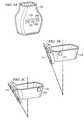
- FIGS. 2A-2Dshow a device used in medical procedures and a plurality of configurations of corresponding medical device guide brackets adapted according to an embodiment of the present invention
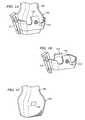
- FIGS. 3A and 3Bshow detail, according to one embodiment, with respect to a housing of the device used in medical procedures of FIG. 1 ;
- FIG. 4shows detail with respect to a housing of a device used in medical procedures according to an alternative embodiment of the invention.
- FIG. 5shows a high level block diagram of ultrasound imaging system adapted according to an embodiment of the present invention.
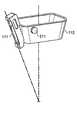
- FIGS. 1A-1Cshow a device used in medical procedures and a corresponding medical device guide bracket adapted according to an embodiment of the present invention.
- FIGS. 1A-1Cillustrate an embodiment wherein medical device guide bracket 110 , shown here as a biopsy needle guide bracket, and assembly 120 , shown here as an ultrasound transducer assembly 120 , are adapted to provide feedback with respect to the desired or proper placement of medical device guide 111 disposed on medical device guide bracket 110 without introducing protuberances or other structure to the surface of assembly 120 .
- embodiments of the present inventionmay be utilized with respect to any number of medical devices.
- embodiments of the present inventionmay be utilized with respect to needles, catheters, drills, saws, scalpels, stints, and/or the like.
- embodiments of the inventionmay be utilized with respect to numerous devices used in performing medical procedures, such as laproscopic instruments, probes, catheters, and/or the like.
- FIG. 1Ashows medical device guide bracket 110 installed upon assembly 120 .
- Medical device guide bracket 110 of the illustrated embodimentis shaped to substantially correspond to a shape of a relevant portion of assembly 120 . Accordingly, medical device guide bracket 110 presents a form factor which is minimally obtrusive with respect to an operator using assembly 120 .
- medical device guide bracket 110includes spring clip portions 112 (more readily visible in FIG. 1B ) which cooperate with corresponding structure of assembly 120 (e.g., shoulder portion 122 which is more readily visible in FIG. 1C ) to hold medical device guide bracket 110 in place when properly positioned on assembly 120 .
- the shape of medical device guide bracket 110may be utilized to generally guide the positioning of medical device guide bracket onto assembly 120 .
- the shape of medical device guide bracket 110 and the shape of assembly 120prevent medical device guide bracket 110 from being placed on assembly 120 in certain undesired orientations.
- the shape of medical device guide bracket 110 and the shape of assembly 120alone do not prevent improper positioning of medical device guide bracket 110 upon assembly 120 of the illustrated embodiment.
- medical device guide bracket 110may be rotated 180° with respect to assembly 120 such that the front of medical device guide bracket 110 is facing the rear. Additionally or alternatively, medical device guide bracket 110 may not be fully engaged with assembly 120 , although provided in a proper orientation.
- medical device guide bracket 110may be partially slid onto assembly 120 without fully engaging assembly 120 .
- Medical device guide bracket 110 being improperly positioned on assembly 120may result in medical device guide 111 not providing desired guidance with respect to a medical device.
- assembly 120may be used to provide ultrasonic imaging of a cyst, for which a biopsy is to be performed, and surrounding tissue.
- the assembly 120may be adjusted to provide the subject cyst, as shown in an image presented by an ultrasound imaging device, in a position corresponding to the track of a needle inserted through medical device guide 111 , when medical device guide 111 is positioned properly with respect to assembly 120 .
- medical device guide bracket 110is improperly installed on assembly 120 , medical device guide 111 may not be positioned properly with respect to assembly 120 . Accordingly, a physician relying upon medical device guide 111 to guide a biopsy needle to a target cyst may instead be guided to a different area, perhaps causing serious injury to a patient.
- medical device guide bracket 110 and assembly 120 of the illustrated embodimentare adapted to provide feedback with respect to the desired or proper placement of medical device guide bracket 110 , and thus medical device guide 111 , upon assembly 120 .
- feedback with respect to proper placement of medical device guide bracket 110is provided according to the illustrated embodiment without introducing protuberances or other structure to the surface of assembly 120 .
- a preferred embodiment of the inventionutilizes Hall effect sensor 125 placed within a housing of assembly 120 and magnet 115 correspondingly placed within the structure of medical device guide bracket 110 to provide feedback with respect to the proper placement of medical device guide bracket 110 upon assembly 120 .
- magnet 115is placed in proximity to Hall effect sensor 125
- the conducting properties of Hall effect sensor 125are altered.
- a control system coupled to Hall effect sensor 125may analyze signals received from Hall effect sensor 125 to determine that a magnet, presumably magnet 115 , is placed in juxtaposition therewith and thus medical device guide bracket 110 is properly positioned.
- Hall effect sensor 125 and corresponding magnet 115are preferably disposed to be juxtaposed when medical device guide bracket 110 engages assembly 120 in the desired orientation and has engaged assembly 120 to the proper extent.
- embodiments of the inventionmay present exterior surfaces of medical device guide bracket 110 which do not present surface features associated with implementation of a sensor.
- magnet 115 of embodiments of the present inventionmay be disposed with a wall of medical device guide bracket 110 without a protrusion in an exterior surface of medical device guide bracket 110 where magnet 115 is sufficiently thin and/or the wall of medical device guide bracket 110 is sufficiently thick.
- Such an embodimentmay be advantageous where it is desired to eliminate a potential point of stress or other discomfort experienced by a user holding assembly 120 having medical device guide bracket 110 attached thereto.
- embodiments of the present inventioneliminate surface perturbations used with respect to properly positioning medical device guide bracket 110 irrespective of whether medical device guide bracket 110 itself has surface perturbations thereon.
- Magnet 115 of embodiments of the inventionis selected to provide a size and magnetic field which results in signals being provided by Hall effect sensor 125 indicative of when medical device guide bracket 110 is placed in a desired position.
- the size of magnet 115may be selected so as to cause Hall effect sensor 125 to provide signals indicative of when medical device guide bracket 110 is placed in a desired position only when magnet 115 is positioned within a very small area.
- the magnet 115may be oriented in medical device guide bracket 110 such that the magnetic field provided thereby is polarized or otherwise orientated to cause Hall effect sensor 125 to provide signals indicative of when medical device guide bracket 110 is placed in a desired position only when magnet 115 is positioned within a very small area.
- Magnet 115 and/or Hall effect sensor 125 of embodiments of the inventionmay additionally or alternatively be adapted to provide information in addition to when medical device guide bracket 110 is placed in a desired position.
- magnet 115 and Hall effect sensor 125may cooperate to provide a first signal when magnet 115 is within proximity to Hall effect sensor 125 , such as may be used by a controller coupled to Hall effect sensor 125 to determine that medical device guide bracket 110 is near to its proper position.
- Magnet 115 and Hall effect sensor 125 of the foregoing examplepreferably provide a second signal when magnet 115 is in juxtaposition with sensor 125 , such as may be used by the controller to determine that medical device guide bracket 110 is in its proper position.
- the foregoing first and second signalsmay be provided as a result of Hall effect sensor 125 providing different variations in conducting as a function of the strength of the field experienced from magnet 115 , the relative positions of one or more poles of magnet 115 with respect to Hall effect sensor 125 , etcetera.
- Information in addition to when medical device guide bracket 110 is placed in a desired position provided by magnet 115 and/or Hall effect sensor 125 of embodiments of the inventionmay include information with respect to a configuration of medical device guide bracket 110 .
- Hall effect sensor 125may comprise a plurality of sensing positions, such as sensing positions 221 - 223 shown in FIG. 2A .
- Different configurations of medical device guide bracket 110may be provided with a magnet disposed in a position corresponding to different ones of sensing positions 221 - 223 .
- medical device guide bracket 110 of FIG. 2Bhaving medical device guide 111 configured for relatively deep needle penetration, has magnet 211 disposed at a first position corresponding to sensing position 221 .
- a third medical device guide bracket(not shown) may have a different configuration, such as medical device guide 111 configured for needle penetration to a depth between that of the aforementioned relatively deep needle penetration and relatively shallow needle penetration.
- FIG. 2Dan embodiment wherein medical device guide 111 is pivotally coupled to medical device guide bracket 110 for selectable adjustment of medical device guide 111 is shown.
- medical device guide 111 of the illustrated embodimentis adjusted, such as to select a particular depth of needle penetration, arm 231 slides, thereby changing the position of magnet 215 .
- Sensor 215using sensing positions 221 - 223 or perhaps continuous sensing along the length of sensor 215 , detects the position of magnet 215 and thus the configuration of medical device guide 111 .
- an embodiment of the present inventiondetect that each of the foregoing medical device guide brackets are properly positioned upon assembly 120 , but such an embodiment may further determine the configuration of the medical device guide bracket by analyzing the particular Hall effect sensor or sensors detecting the proximity of a magnet.
- a determination with respect to the configuration of the medical device guide bracketmay be utilized in providing information with respect to the operation of a system to a user thereof.
- embodiments of the present inventionmay provide a warning to a user that an improper operational mode has been selected for use with the presently detected medical device guide bracket configuration.
- embodiments of the inventionmay operate to provide information with respect to the presently detected medical device guide bracket configuration, such as an operational mode (e.g., software setting) which should be used with the medical device guide bracket configuration, a depth of needle penetration associated with the medical device guide bracket configuration, or other information associated with or relevant to the medical device guide bracket configuration, its use, etcetera.
- an operational modee.g., software setting
- a depth of needle penetration associated with the medical device guide bracket configuratione.g., software setting
- an embodiment of the inventionmay make determinations with respect to the proper positioning of 7 different configurations of medical device guide bracket configurations (e.g., 1 using a magnet at sensing position 221 , 1 using a magnet at sensing position 222 , 1 using a magnet at sensing position 223 , 1 using a magnet at sensing positions 221 and 222 , 1 using a magnet at sensing positions 221 and 223 , 1 using a magnet at sensing positions 222 and 223 , and 1 using a magnet at sensing positions 221 , 222 , and 223 ).
- medical device guide bracket configurationse.g., 1 using a magnet at sensing position 221 , 1 using a magnet at sensing position 222 , 1 using a magnet at sensing position 223 , 1 using a magnet at sensing positions 221 and 223 , 1 using a magnet at sensing positions 222 and 223 , and 1 using a magnet at sensing positions 221 , 222 , and 223 ).
- Hall effect sensor 125 of the illustrated embodimentis placed along a centerline of housing 320 of assembly 120 .
- Hall effect sensor 125 of embodiments of the inventionis disposed as shown in FIG. 3A to provide a configuration which is readily implemented with respect to a two-piece housing assembly and which does not interfere with other components, such as a transducer array, signal cables, etcetera. It should be appreciated, however, that embodiments of the present invention may implement various placements of sensors in addition to or in the alternative to that shown.
- Embodiments of the present inventionmay utilize a plurality of sensors.
- second Hall effect sensor 425may be disposed at a 90° angle with respect to Hall effect sensor 125 , as shown in FIG. 4 .
- an additional sensormay be disposed in a second housing of assembly 120 substantially as illustrated in FIG. 2A .
- Such an additional sensormay be utilized in providing additional information to a user.
- a second sensormay be used to detect when medical device guide bracket 110 is disposed in a particular incorrect position and thus a controller coupled thereto may provide appropriate information, such as instructions as to how to correct the installation of medical device guide bracket 110 .
- a single magnet 115is provided while 2 Hall effect sensors 125 are provided. Thus when a particular one of the Hall effect sensors 125 experiences a magnet field, an orientation of medical device guide bracket 110 may be determined.
- the use of a plurality of sensorsmay additionally or alternatively be used according to embodiments of the invention to provide a high level of confidence with respect to the positioning of medical device guide bracket 110 .
- the embodiment of FIG. 4includes Hall effect sensor 125 disposed within a front surface of assembly 120 provided in combination with Hall effect sensor 425 disposed within a side surface of assembly 120 and medical device guide bracket 110 is provided with magnets 115 and 415 disposed to correspond to these Hall effect sensors when medical device guide bracket 110 is properly positioned on assembly 120 .
- a controller coupled to the Hall effect sensorsmay not determine that medical device guide bracket 110 is properly positioned until an appropriate signal is received from each such Hall effect sensor. Accordingly, an anomalous signal from one such Hall effect sensor, such as may result from a malfunctioning sensor or being exposed to a stray magnetic field, will be unlikely to result in an incorrect determination that medical device guide bracket 110 is properly positioned.
- embodiments of the present inventionmay implement various sensor technologies, such as optical sensors, capacitive coupled sensors, inductive coupled sensors, RFID sensors, and/or the like, in the alternative to or in combination with the aforementioned Hall effect sensors.
- embodiments of the present inventionmay dispose a light pipe (e.g., fiber optic line) such that an end thereof is flush with an external surface of assembly 120 (e.g., at a position corresponding to a position of an edge of medical device guide bracket 110 when installed on assembly 120 ) and another end thereof in communication with an optic sensor (e.g., a photo diode).
- a light pipee.g., fiber optic line
- an optical sensor embodiment of the present inventionutilizes a plurality of light pipes, preferably disposed at different locations on assembly 120 , in order to provide a high level of confidence with respect to determining when medical device guide bracket 110 is disposed in a proper position.
- an embodimentmay detect that one or more optical sensors are obscured by medical device guide bracket 110 and that one or more optical sensors are not obscured by medical device guide bracket 110 (e.g., such as by a hole or transparent part of medical device guide bracket 110 being provided in juxtaposition with a particular light pipe at the surface of assembly 120 ).
- a light sourceis provided within the assembly housing (such as at a position corresponding to Hall effect sensor 125 of FIG. 4 ) with a light window allowing the light to pass through the assembly housing.
- the medical device guide bracketmay comprise a light pipe embedded therein and having a plurality of light interfaces facing the assembly (such as at positions corresponding to magnets 115 and 415 of FIG. 4 ).
- the assembly housingmay further include a light window allowing light to pass through an optical sensor disposed therein (such as at a position corresponding to Hall effect sensor 425 of FIG. 4 ). Accordingly, when positioned correctly, light will pass from the light source, through the light pipe, to the optical sensor.
- the optical sensormay be designed to react to specific light frequency in order to avoid false determinations that a medical device guide bracket has been installed due to detecting ambient light.
- An embodiment of the invention utilizing RFID technologymay comprise an RFID tag within the medical device guide bracket which is powered and read when in proximity to a RFID sensor disposed within the assembly. When in close proximity to the RFID sensor, the RFID tag may be powered and data read therefrom. Information provided by the RFID tag may indicate the medical device guide bracket configuration and/or other information.
- Ultrasound imaging system 500 of the illustrated embodimentincludes ultrasound imaging device 530 (such as may comprise the TITANTM, the 180PLUSTM, the ELITETM, or the ILOOKTM ultrasound imaging devices available from SonoSite, Inc., Bothell, Wash. U.S.A.) coupled to assembly 120 via cable 533 .
- Ultrasound imaging device 530 of the illustrated embodimentincludes controller 531 , such as may comprise a microcontroller, memory, and an instruction set providing operation as described herein, and display 532 , such as may comprise a liquid crystal display (LCD) or other screen for displaying graphical images and/or text.
- Assembly 120 of the illustrated embodimentincludes transducer array 521 and sensors 525 .
- signals of one or more transducer and/or sensormay share a common signal path, such as through multiplexing, signal combining, etcetera.
- Sensors 525may implement any desired sensor technology, such as Hall effect, optical, capacitive, inductive, and/or the like.
- Medical device guide bracket 111(shown only partially engaging assembly 120 ) illustrated in FIG. 5 includes corresponding sensor members 515 , such as may comprise a magnet, an opaque surface, a transparent surface, a plate, a coil, and/or the like, which cooperate with sensors 525 to provide feedback with respect to the desired or proper placement of medical device guide bracket 110 , and thus medical device guide 111 .
- a usermay select an operational mode of ultrasound imaging device 530 with which medical device guide 111 should be used. For example, a user may select a biopsy mode in which a particular image feature, corresponding to a tissue growth of interest, is targeted in an image displayed on display 532 (e.g., the tissue growth is focused upon and placed at a particular position in the displayed image).
- Controller 531may analyze signals from sensors 525 and make a determination with respect to whether medical device guide bracket 110 is properly positioned with respect to assembly 120 . As mentioned above, such a determination may include analyzing signals associated with one or more of sensors 525 to provide information with respect to how a user may correct the placement of medical device guide bracket 110 , such as by providing instructions and/or graphics on display 532 .
- controller 531may prevent operation of ultrasound imaging device 530 in the selected mode. If it is determined that medial device guide bracket 110 is properly positioned, controller 531 may allow operation of ultrasound imaging device 530 in the desired mode. For example, display 532 may provide a real-time image of the target tissue and surrounding tissue, showing the progression of a needle guided by medical device guide 111 toward the target tissue. Because medical device guide bracket 110 is properly positioned with respect to assembly 120 , and thus medical device guide 111 is properly positioned for the imaging mode selected, a physician using ultrasound imaging system 500 to perform a biopsy procedure may be confident that the needle will obtain a sample of the target tissue.
Landscapes
- Health & Medical Sciences (AREA)
- Surgery (AREA)
- Life Sciences & Earth Sciences (AREA)
- Biomedical Technology (AREA)
- Nuclear Medicine, Radiotherapy & Molecular Imaging (AREA)
- Engineering & Computer Science (AREA)
- Pathology (AREA)
- Heart & Thoracic Surgery (AREA)
- Medical Informatics (AREA)
- Molecular Biology (AREA)
- Animal Behavior & Ethology (AREA)
- General Health & Medical Sciences (AREA)
- Public Health (AREA)
- Veterinary Medicine (AREA)
- Ultra Sonic Daignosis Equipment (AREA)
Abstract
Description
Claims (26)
Priority Applications (2)
| Application Number | Priority Date | Filing Date | Title |
|---|---|---|---|
| US11/216,735US8147408B2 (en) | 2005-08-31 | 2005-08-31 | Medical device guide locator |
| PCT/US2006/032705WO2007027470A2 (en) | 2005-08-31 | 2006-08-23 | Medical device guide locator |
Applications Claiming Priority (1)
| Application Number | Priority Date | Filing Date | Title |
|---|---|---|---|
| US11/216,735US8147408B2 (en) | 2005-08-31 | 2005-08-31 | Medical device guide locator |
Publications (2)
| Publication Number | Publication Date |
|---|---|
| US20070049822A1 US20070049822A1 (en) | 2007-03-01 |
| US8147408B2true US8147408B2 (en) | 2012-04-03 |
Family
ID=37805254
Family Applications (1)
| Application Number | Title | Priority Date | Filing Date |
|---|---|---|---|
| US11/216,735Active2031-01-03US8147408B2 (en) | 2005-08-31 | 2005-08-31 | Medical device guide locator |
Country Status (2)
| Country | Link |
|---|---|
| US (1) | US8147408B2 (en) |
| WO (1) | WO2007027470A2 (en) |
Cited By (30)
| Publication number | Priority date | Publication date | Assignee | Title |
|---|---|---|---|---|
| US20090226069A1 (en)* | 2008-03-07 | 2009-09-10 | Inneroptic Technology, Inc. | Systems and methods for displaying guidance data based on updated deformable imaging data |
| US20100168766A1 (en)* | 2008-12-25 | 2010-07-01 | Shenzhen Mindray Bio-Medical Electronics Co., Ltd. | Puncture needle holder |
| US20100198045A1 (en)* | 2006-08-02 | 2010-08-05 | Inneroptic Technology Inc. | System and method of providing real-time dynamic imagery of a medical procedure site using multiple modalities |
| US8554307B2 (en) | 2010-04-12 | 2013-10-08 | Inneroptic Technology, Inc. | Image annotation in image-guided medical procedures |
| US8585598B2 (en) | 2009-02-17 | 2013-11-19 | Inneroptic Technology, Inc. | Systems, methods, apparatuses, and computer-readable media for image guided surgery |
| US8641621B2 (en) | 2009-02-17 | 2014-02-04 | Inneroptic Technology, Inc. | Systems, methods, apparatuses, and computer-readable media for image management in image-guided medical procedures |
| US8670816B2 (en) | 2012-01-30 | 2014-03-11 | Inneroptic Technology, Inc. | Multiple medical device guidance |
| US8805047B2 (en) | 2009-04-14 | 2014-08-12 | Fujifilm Sonosite, Inc. | Systems and methods for adaptive volume imaging |
| US8861822B2 (en) | 2010-04-07 | 2014-10-14 | Fujifilm Sonosite, Inc. | Systems and methods for enhanced imaging of objects within an image |
| US9211110B2 (en) | 2013-03-15 | 2015-12-15 | The Regents Of The University Of Michigan | Lung ventillation measurements using ultrasound |
| US9257220B2 (en) | 2013-03-05 | 2016-02-09 | Ezono Ag | Magnetization device and method |
| US9265572B2 (en) | 2008-01-24 | 2016-02-23 | The University Of North Carolina At Chapel Hill | Methods, systems, and computer readable media for image guided ablation |
| USD754357S1 (en) | 2011-08-09 | 2016-04-19 | C. R. Bard, Inc. | Ultrasound probe head |
| US9459087B2 (en) | 2013-03-05 | 2016-10-04 | Ezono Ag | Magnetic position detection system |
| US9597008B2 (en) | 2011-09-06 | 2017-03-21 | Ezono Ag | Imaging probe and method of obtaining position and/or orientation information |
| US9675319B1 (en) | 2016-02-17 | 2017-06-13 | Inneroptic Technology, Inc. | Loupe display |
| US9901406B2 (en) | 2014-10-02 | 2018-02-27 | Inneroptic Technology, Inc. | Affected region display associated with a medical device |
| US9949700B2 (en) | 2015-07-22 | 2018-04-24 | Inneroptic Technology, Inc. | Medical device approaches |
| US10178984B2 (en) | 2014-01-10 | 2019-01-15 | Soma Research, Llc | Needle guidance systems for use with ultrasound devices |
| US10188467B2 (en) | 2014-12-12 | 2019-01-29 | Inneroptic Technology, Inc. | Surgical guidance intersection display |
| US10278778B2 (en) | 2016-10-27 | 2019-05-07 | Inneroptic Technology, Inc. | Medical device navigation using a virtual 3D space |
| US10314559B2 (en) | 2013-03-14 | 2019-06-11 | Inneroptic Technology, Inc. | Medical device guidance |
| US10434278B2 (en) | 2013-03-05 | 2019-10-08 | Ezono Ag | System for image guided procedure |
| US10639008B2 (en) | 2009-10-08 | 2020-05-05 | C. R. Bard, Inc. | Support and cover structures for an ultrasound probe head |
| US10820885B2 (en) | 2012-06-15 | 2020-11-03 | C. R. Bard, Inc. | Apparatus and methods for detection of a removable cap on an ultrasound probe |
| US11103213B2 (en) | 2009-10-08 | 2021-08-31 | C. R. Bard, Inc. | Spacers for use with an ultrasound probe |
| US11259879B2 (en) | 2017-08-01 | 2022-03-01 | Inneroptic Technology, Inc. | Selective transparency to assist medical device navigation |
| US11464578B2 (en) | 2009-02-17 | 2022-10-11 | Inneroptic Technology, Inc. | Systems, methods, apparatuses, and computer-readable media for image management in image-guided medical procedures |
| US11484365B2 (en) | 2018-01-23 | 2022-11-01 | Inneroptic Technology, Inc. | Medical image guidance |
| US11701088B2 (en) | 2019-03-05 | 2023-07-18 | Ethos Medical, Inc. | Systems, methods, and devices for instrument guidance |
Families Citing this family (71)
| Publication number | Priority date | Publication date | Assignee | Title |
|---|---|---|---|---|
| US8784336B2 (en) | 2005-08-24 | 2014-07-22 | C. R. Bard, Inc. | Stylet apparatuses and methods of manufacture |
| ES2524303T3 (en) | 2006-05-08 | 2014-12-05 | C.R. Bard, Inc. | User interface and methods for an ultrasound presentation device |
| US8388546B2 (en) | 2006-10-23 | 2013-03-05 | Bard Access Systems, Inc. | Method of locating the tip of a central venous catheter |
| US7794407B2 (en) | 2006-10-23 | 2010-09-14 | Bard Access Systems, Inc. | Method of locating the tip of a central venous catheter |
| US8360977B2 (en) | 2007-09-27 | 2013-01-29 | Baxter International Inc. | Continuity circuits for detecting access disconnection |
| US8632526B2 (en)* | 2007-11-07 | 2014-01-21 | Amo Development, Llc | System and method of interfacing a surgical laser with an eye |
| ES2465915T3 (en) | 2007-11-26 | 2014-06-09 | C.R. Bard, Inc. | Integrated system for intravascular catheter placement |
| US10449330B2 (en) | 2007-11-26 | 2019-10-22 | C. R. Bard, Inc. | Magnetic element-equipped needle assemblies |
| US10751509B2 (en) | 2007-11-26 | 2020-08-25 | C. R. Bard, Inc. | Iconic representations for guidance of an indwelling medical device |
| US10524691B2 (en) | 2007-11-26 | 2020-01-07 | C. R. Bard, Inc. | Needle assembly including an aligned magnetic element |
| US8781555B2 (en) | 2007-11-26 | 2014-07-15 | C. R. Bard, Inc. | System for placement of a catheter including a signal-generating stylet |
| US9649048B2 (en) | 2007-11-26 | 2017-05-16 | C. R. Bard, Inc. | Systems and methods for breaching a sterile field for intravascular placement of a catheter |
| US9521961B2 (en) | 2007-11-26 | 2016-12-20 | C. R. Bard, Inc. | Systems and methods for guiding a medical instrument |
| US8849382B2 (en) | 2007-11-26 | 2014-09-30 | C. R. Bard, Inc. | Apparatus and display methods relating to intravascular placement of a catheter |
| US9636031B2 (en) | 2007-11-26 | 2017-05-02 | C.R. Bard, Inc. | Stylets for use with apparatus for intravascular placement of a catheter |
| US8478382B2 (en) | 2008-02-11 | 2013-07-02 | C. R. Bard, Inc. | Systems and methods for positioning a catheter |
| US20100041990A1 (en)* | 2008-08-13 | 2010-02-18 | John Schlitt | Needle Guides for Catheter Delivery |
| US9901714B2 (en) | 2008-08-22 | 2018-02-27 | C. R. Bard, Inc. | Catheter assembly including ECG sensor and magnetic assemblies |
| US8437833B2 (en) | 2008-10-07 | 2013-05-07 | Bard Access Systems, Inc. | Percutaneous magnetic gastrostomy |
| US20100106015A1 (en) | 2008-10-23 | 2010-04-29 | Norris Perry R | Medical device alignment |
| US8162852B2 (en)* | 2008-10-23 | 2012-04-24 | Devicor Medical Products, Inc. | Methods for medical device alignment |
| JP5795576B2 (en) | 2009-06-12 | 2015-10-14 | バード・アクセス・システムズ,インコーポレーテッド | Method of operating a computer-based medical device that uses an electrocardiogram (ECG) signal to position an intravascular device in or near the heart |
| US9532724B2 (en) | 2009-06-12 | 2017-01-03 | Bard Access Systems, Inc. | Apparatus and method for catheter navigation using endovascular energy mapping |
| EP2464407A4 (en) | 2009-08-10 | 2014-04-02 | Bard Access Systems Inc | Devices and methods for endovascular electrography |
| US8496592B2 (en) | 2009-10-09 | 2013-07-30 | Stephen F. Ridley | Clamp for a medical probe device |
| WO2011097312A1 (en) | 2010-02-02 | 2011-08-11 | C.R. Bard, Inc. | Apparatus and method for catheter navigation and tip location |
| US20110245659A1 (en)* | 2010-04-01 | 2011-10-06 | Sonosite, Inc. | Systems and methods to assist with internal positioning of instruments |
| EP4122385A1 (en) | 2010-05-28 | 2023-01-25 | C. R. Bard, Inc. | Insertion guidance system for needles and medical components |
| EP2912999B1 (en) | 2010-05-28 | 2022-06-29 | C. R. Bard, Inc. | Apparatus for use with needle insertion guidance system |
| US8527033B1 (en)* | 2010-07-01 | 2013-09-03 | Sonosite, Inc. | Systems and methods for assisting with internal positioning of instruments |
| BR112013002431B1 (en) | 2010-08-20 | 2021-06-29 | C.R. Bard, Inc | SYSTEM FOR RECONFIRMING THE POSITION OF A CATHETER INSIDE A PATIENT |
| US8425425B2 (en) | 2010-09-20 | 2013-04-23 | M. Dexter Hagy | Virtual image formation method for an ultrasound device |
| DE102010046948A1 (en)* | 2010-09-29 | 2011-12-08 | Richard Wolf Gmbh | Surgical target device for positioning e.g. tibial drilling channel in knee joint at tibial plateau, has markers or sensors arranged at guide arm to detect position of target device, and drill guide displaced along guide arm |
| DE102010042012A1 (en)* | 2010-10-05 | 2012-04-05 | Aces Gmbh | Instrument for implantation of pedicle during spinal column surgery, has ultrasound probe for measuring distance between instrument and cortical outer zone of pedicle |
| US8801693B2 (en) | 2010-10-29 | 2014-08-12 | C. R. Bard, Inc. | Bioimpedance-assisted placement of a medical device |
| RU2609203C2 (en)* | 2011-07-06 | 2017-01-30 | Си.Ар. Бард, Инк. | Determination and calibration of needle length for needle guidance system |
| USD724745S1 (en) | 2011-08-09 | 2015-03-17 | C. R. Bard, Inc. | Cap for an ultrasound probe |
| US9211107B2 (en) | 2011-11-07 | 2015-12-15 | C. R. Bard, Inc. | Ruggedized ultrasound hydrogel insert |
| US20140275990A1 (en)* | 2013-03-15 | 2014-09-18 | Soma Access Systems, Llc | Ultrasound Guidance System Including Tagged Probe Assembly |
| CN105120766B (en) | 2013-04-12 | 2020-03-27 | 皇家飞利浦有限公司 | Imaging device for brachytherapy or biopsy |
| KR102209757B1 (en)* | 2013-12-27 | 2021-01-29 | 삼성메디슨 주식회사 | A Ultrasound Probe Caring system |
| WO2015120256A2 (en) | 2014-02-06 | 2015-08-13 | C.R. Bard, Inc. | Systems and methods for guidance and placement of an intravascular device |
| DE102014104179A1 (en) | 2014-03-26 | 2015-10-01 | Aesculap Ag | Control for safe assembly and disassembly of two functional units of a multi-part medical device |
| WO2015159129A1 (en)* | 2014-04-16 | 2015-10-22 | B-K Medical Aps | Multi-purpose instrument guide |
| US10507038B2 (en) | 2014-11-12 | 2019-12-17 | Civco Medical Instruments Co., Inc. | Needle guide devices for mounting on imaging transducers or adaptors on imaging transducer, imaging transducers for mounting needle guide devices and adaptors for imaging transducers for mounting needle guide devices thereon |
| US10973584B2 (en) | 2015-01-19 | 2021-04-13 | Bard Access Systems, Inc. | Device and method for vascular access |
| WO2016210325A1 (en) | 2015-06-26 | 2016-12-29 | C.R. Bard, Inc. | Connector interface for ecg-based catheter positioning system |
| US11000207B2 (en) | 2016-01-29 | 2021-05-11 | C. R. Bard, Inc. | Multiple coil system for tracking a medical device |
| US10786224B2 (en) | 2016-04-21 | 2020-09-29 | Covidien Lp | Biopsy devices and methods of use thereof |
| US11331161B2 (en) | 2018-03-23 | 2022-05-17 | Covidien Lp | Surgical assemblies facilitating tissue marking and methods of use thereof |
| US10992079B2 (en) | 2018-10-16 | 2021-04-27 | Bard Access Systems, Inc. | Safety-equipped connection systems and methods thereof for establishing electrical connections |
| US11090122B2 (en)* | 2019-02-25 | 2021-08-17 | Verb Surgical Inc. | Systems and methods for magnetic sensing and docking with a trocar |
| US11517294B2 (en) | 2019-05-07 | 2022-12-06 | Covidien Lp | Biopsy devices and methods of use thereof |
| JP2022538126A (en)* | 2019-06-26 | 2022-08-31 | イーソス メディカル,インク. | Systems, methods and apparatus for instrument guidance |
| US11759166B2 (en) | 2019-09-20 | 2023-09-19 | Bard Access Systems, Inc. | Automatic vessel detection tools and methods |
| US11877810B2 (en) | 2020-07-21 | 2024-01-23 | Bard Access Systems, Inc. | System, method and apparatus for magnetic tracking of ultrasound probe and generation of 3D visualization thereof |
| EP4185209A1 (en) | 2020-08-04 | 2023-05-31 | Bard Access Systems, Inc. | System and method for optimized medical component insertion monitoring and imaging enhancement |
| WO2022035760A1 (en) | 2020-08-10 | 2022-02-17 | Bard Access Systems, Inc. | System and method for generating vessel representations in mixed reality/virtual reality |
| US11992363B2 (en) | 2020-09-08 | 2024-05-28 | Bard Access Systems, Inc. | Dynamically adjusting ultrasound-imaging systems and methods thereof |
| CN216257185U (en) | 2020-09-10 | 2022-04-12 | 巴德阿克塞斯系统股份有限公司 | Ultrasound Probes and Ultrasound Systems |
| WO2022072727A2 (en) | 2020-10-02 | 2022-04-07 | Bard Access Systems, Inc. | Ultrasound systems and methods for sustained spatial attention |
| EP4228516A1 (en) | 2020-10-15 | 2023-08-23 | Bard Access Systems, Inc. | Ultrasound imaging system for generation of a three-dimensional ultrasound image |
| CN216933458U (en) | 2020-11-24 | 2022-07-12 | 巴德阿克塞斯系统股份有限公司 | Object recognition and needle guidance system |
| CN114569156A (en) | 2020-12-01 | 2022-06-03 | 巴德阿克塞斯系统股份有限公司 | Ultrasound imaging system and method for identifying one or more of a plurality of blood vessels |
| CN114569155A (en) | 2020-12-01 | 2022-06-03 | 巴德阿克塞斯系统股份有限公司 | Ultrasound imaging system and method for obtaining ultrasound image by the same |
| CN217960146U (en) | 2021-04-15 | 2022-12-06 | 巴德阿克塞斯系统股份有限公司 | Ultrasound imaging system |
| CN116058873A (en) | 2021-11-03 | 2023-05-05 | 巴德阿克塞斯系统股份有限公司 | Interoperation optimization function through Doppler and image-based vessel discrimination |
| US12433567B2 (en) | 2022-03-16 | 2025-10-07 | Bard Access Systems, Inc. | Ultrasound imaging system |
| US12102481B2 (en) | 2022-06-03 | 2024-10-01 | Bard Access Systems, Inc. | Ultrasound probe with smart accessory |
| US12137989B2 (en) | 2022-07-08 | 2024-11-12 | Bard Access Systems, Inc. | Systems and methods for intelligent ultrasound probe guidance |
| US20240065673A1 (en)* | 2022-08-24 | 2024-02-29 | Bard Access Systems, Inc. | Ultrasound Smart Port Accessory |
Citations (16)
| Publication number | Priority date | Publication date | Assignee | Title |
|---|---|---|---|---|
| US5003965A (en) | 1988-09-14 | 1991-04-02 | Meditron Corporation | Medical device for ultrasonic treatment of living tissue and/or cells |
| US5928219A (en) | 1998-09-29 | 1999-07-27 | Siemens Medical Systems, Inc. | Fail-safe needle guide mount for ultrasonic probes |
| WO2000076575A2 (en) | 1999-06-11 | 2000-12-21 | Spectrx, Inc. | Alignment devices and methods for fluid extraction from tissue and substance delivery |
| US20030004414A1 (en) | 2001-05-31 | 2003-01-02 | Mclaughlin Glen | System and method for phase inversion ultrasonic imaging |
| US6618206B2 (en) | 2001-10-20 | 2003-09-09 | Zonare Medical Systems, Inc. | System and method for acoustic imaging at two focal lengths with a single lens |
| US6663567B2 (en) | 2002-03-19 | 2003-12-16 | Zonare Medical Systems, Inc. | System and method for post-processing ultrasound color doppler imaging |
| US6685645B1 (en) | 2001-10-20 | 2004-02-03 | Zonare Medical Systems, Inc. | Broad-beam imaging |
| US6733455B2 (en) | 1999-08-20 | 2004-05-11 | Zonare Medical Systems, Inc. | System and method for adaptive clutter filtering in ultrasound color flow imaging |
| US6773399B2 (en) | 2001-10-20 | 2004-08-10 | Zonare Medical Systems, Inc. | Block-switching in ultrasound imaging |
| US20040235142A1 (en) | 2003-04-04 | 2004-11-25 | Organ Recovery Systems | Method and apparatus for holding a plurality of tubes connectible to an organ or tissue container |
| US6866632B1 (en) | 2002-09-18 | 2005-03-15 | Zonare Medical Systems, Inc. | Adaptive receive aperture for ultrasound image reconstruction |
| US6896658B2 (en) | 2001-10-20 | 2005-05-24 | Zonare Medical Systems, Inc. | Simultaneous multi-mode and multi-band ultrasonic imaging |
| EP1552792A1 (en) | 2003-12-10 | 2005-07-13 | SonoSite, Inc. | Guide for medical device |
| US6936008B2 (en) | 1999-08-20 | 2005-08-30 | Zonare Medical Systems, Inc. | Ultrasound system with cableless coupling assembly |
| US6980419B2 (en) | 2003-03-12 | 2005-12-27 | Zonare Medical Systems, Inc. | Portable ultrasound unit and docking station |
| US20060025677A1 (en)* | 2003-10-17 | 2006-02-02 | Verard Laurent G | Method and apparatus for surgical navigation |
- 2005
- 2005-08-31USUS11/216,735patent/US8147408B2/enactiveActive
- 2006
- 2006-08-23WOPCT/US2006/032705patent/WO2007027470A2/enactiveApplication Filing
Patent Citations (19)
| Publication number | Priority date | Publication date | Assignee | Title |
|---|---|---|---|---|
| US5003965A (en) | 1988-09-14 | 1991-04-02 | Meditron Corporation | Medical device for ultrasonic treatment of living tissue and/or cells |
| US5928219A (en) | 1998-09-29 | 1999-07-27 | Siemens Medical Systems, Inc. | Fail-safe needle guide mount for ultrasonic probes |
| WO2000076575A2 (en) | 1999-06-11 | 2000-12-21 | Spectrx, Inc. | Alignment devices and methods for fluid extraction from tissue and substance delivery |
| US6733455B2 (en) | 1999-08-20 | 2004-05-11 | Zonare Medical Systems, Inc. | System and method for adaptive clutter filtering in ultrasound color flow imaging |
| US6936008B2 (en) | 1999-08-20 | 2005-08-30 | Zonare Medical Systems, Inc. | Ultrasound system with cableless coupling assembly |
| DE10224234A1 (en) | 2001-05-31 | 2003-01-09 | Novasonics Inc | System and method for phase reversal ultrasound imaging |
| US6866631B2 (en) | 2001-05-31 | 2005-03-15 | Zonare Medical Systems, Inc. | System for phase inversion ultrasonic imaging |
| US20030004414A1 (en) | 2001-05-31 | 2003-01-02 | Mclaughlin Glen | System and method for phase inversion ultrasonic imaging |
| US6773399B2 (en) | 2001-10-20 | 2004-08-10 | Zonare Medical Systems, Inc. | Block-switching in ultrasound imaging |
| US6618206B2 (en) | 2001-10-20 | 2003-09-09 | Zonare Medical Systems, Inc. | System and method for acoustic imaging at two focal lengths with a single lens |
| US6896658B2 (en) | 2001-10-20 | 2005-05-24 | Zonare Medical Systems, Inc. | Simultaneous multi-mode and multi-band ultrasonic imaging |
| US20050131294A1 (en) | 2001-10-20 | 2005-06-16 | Zonare Medical Systems, Inc. | Ultrasound system for generating a single set of ultrasound pulse firings |
| US6685645B1 (en) | 2001-10-20 | 2004-02-03 | Zonare Medical Systems, Inc. | Broad-beam imaging |
| US6663567B2 (en) | 2002-03-19 | 2003-12-16 | Zonare Medical Systems, Inc. | System and method for post-processing ultrasound color doppler imaging |
| US6866632B1 (en) | 2002-09-18 | 2005-03-15 | Zonare Medical Systems, Inc. | Adaptive receive aperture for ultrasound image reconstruction |
| US6980419B2 (en) | 2003-03-12 | 2005-12-27 | Zonare Medical Systems, Inc. | Portable ultrasound unit and docking station |
| US20040235142A1 (en) | 2003-04-04 | 2004-11-25 | Organ Recovery Systems | Method and apparatus for holding a plurality of tubes connectible to an organ or tissue container |
| US20060025677A1 (en)* | 2003-10-17 | 2006-02-02 | Verard Laurent G | Method and apparatus for surgical navigation |
| EP1552792A1 (en) | 2003-12-10 | 2005-07-13 | SonoSite, Inc. | Guide for medical device |
Non-Patent Citations (1)
| Title |
|---|
| International Search Report & Written Opinion issued for PCT/US2006/032705 dated Mar. 26, 2007. |
Cited By (62)
| Publication number | Priority date | Publication date | Assignee | Title |
|---|---|---|---|---|
| US20100198045A1 (en)* | 2006-08-02 | 2010-08-05 | Inneroptic Technology Inc. | System and method of providing real-time dynamic imagery of a medical procedure site using multiple modalities |
| US8482606B2 (en) | 2006-08-02 | 2013-07-09 | Inneroptic Technology, Inc. | System and method of providing real-time dynamic imagery of a medical procedure site using multiple modalities |
| US10733700B2 (en) | 2006-08-02 | 2020-08-04 | Inneroptic Technology, Inc. | System and method of providing real-time dynamic imagery of a medical procedure site using multiple modalities |
| US10127629B2 (en) | 2006-08-02 | 2018-11-13 | Inneroptic Technology, Inc. | System and method of providing real-time dynamic imagery of a medical procedure site using multiple modalities |
| US11481868B2 (en) | 2006-08-02 | 2022-10-25 | Inneroptic Technology, Inc. | System and method of providing real-time dynamic imagery of a medical procedure she using multiple modalities |
| US9659345B2 (en) | 2006-08-02 | 2017-05-23 | Inneroptic Technology, Inc. | System and method of providing real-time dynamic imagery of a medical procedure site using multiple modalities |
| US9265572B2 (en) | 2008-01-24 | 2016-02-23 | The University Of North Carolina At Chapel Hill | Methods, systems, and computer readable media for image guided ablation |
| US8831310B2 (en) | 2008-03-07 | 2014-09-09 | Inneroptic Technology, Inc. | Systems and methods for displaying guidance data based on updated deformable imaging data |
| US20090226069A1 (en)* | 2008-03-07 | 2009-09-10 | Inneroptic Technology, Inc. | Systems and methods for displaying guidance data based on updated deformable imaging data |
| US20100168766A1 (en)* | 2008-12-25 | 2010-07-01 | Shenzhen Mindray Bio-Medical Electronics Co., Ltd. | Puncture needle holder |
| US8430889B2 (en)* | 2008-12-25 | 2013-04-30 | Shenzhen Mindray Bio-Medical Electronics Co., Ltd | Puncture needle holder |
| US9398936B2 (en) | 2009-02-17 | 2016-07-26 | Inneroptic Technology, Inc. | Systems, methods, apparatuses, and computer-readable media for image guided surgery |
| US8690776B2 (en) | 2009-02-17 | 2014-04-08 | Inneroptic Technology, Inc. | Systems, methods, apparatuses, and computer-readable media for image guided surgery |
| US10398513B2 (en) | 2009-02-17 | 2019-09-03 | Inneroptic Technology, Inc. | Systems, methods, apparatuses, and computer-readable media for image management in image-guided medical procedures |
| US11464575B2 (en) | 2009-02-17 | 2022-10-11 | Inneroptic Technology, Inc. | Systems, methods, apparatuses, and computer-readable media for image guided surgery |
| US11464578B2 (en) | 2009-02-17 | 2022-10-11 | Inneroptic Technology, Inc. | Systems, methods, apparatuses, and computer-readable media for image management in image-guided medical procedures |
| US8585598B2 (en) | 2009-02-17 | 2013-11-19 | Inneroptic Technology, Inc. | Systems, methods, apparatuses, and computer-readable media for image guided surgery |
| US10136951B2 (en) | 2009-02-17 | 2018-11-27 | Inneroptic Technology, Inc. | Systems, methods, apparatuses, and computer-readable media for image guided surgery |
| US9364294B2 (en) | 2009-02-17 | 2016-06-14 | Inneroptic Technology, Inc. | Systems, methods, apparatuses, and computer-readable media for image management in image-guided medical procedures |
| US8641621B2 (en) | 2009-02-17 | 2014-02-04 | Inneroptic Technology, Inc. | Systems, methods, apparatuses, and computer-readable media for image management in image-guided medical procedures |
| US12419695B2 (en) | 2009-02-17 | 2025-09-23 | Inneroptic Technology, Inc. | Systems, methods, apparatuses, and computer-readable media for image management in image-guided medical procedures |
| US8805047B2 (en) | 2009-04-14 | 2014-08-12 | Fujifilm Sonosite, Inc. | Systems and methods for adaptive volume imaging |
| US11998386B2 (en) | 2009-10-08 | 2024-06-04 | C. R. Bard, Inc. | Support and cover structures for an ultrasound probe head |
| US11103213B2 (en) | 2009-10-08 | 2021-08-31 | C. R. Bard, Inc. | Spacers for use with an ultrasound probe |
| US10639008B2 (en) | 2009-10-08 | 2020-05-05 | C. R. Bard, Inc. | Support and cover structures for an ultrasound probe head |
| US9895133B2 (en) | 2010-04-07 | 2018-02-20 | Fujifilm Sonosite, Inc. | System and methods for enhanced imaging of objects within an image |
| US8861822B2 (en) | 2010-04-07 | 2014-10-14 | Fujifilm Sonosite, Inc. | Systems and methods for enhanced imaging of objects within an image |
| US8554307B2 (en) | 2010-04-12 | 2013-10-08 | Inneroptic Technology, Inc. | Image annotation in image-guided medical procedures |
| US9107698B2 (en) | 2010-04-12 | 2015-08-18 | Inneroptic Technology, Inc. | Image annotation in image-guided medical procedures |
| USD754357S1 (en) | 2011-08-09 | 2016-04-19 | C. R. Bard, Inc. | Ultrasound probe head |
| US10758155B2 (en) | 2011-09-06 | 2020-09-01 | Ezono Ag | Imaging probe and method of obtaining position and/or orientation information |
| US10765343B2 (en) | 2011-09-06 | 2020-09-08 | Ezono Ag | Imaging probe and method of obtaining position and/or orientation information |
| US9597008B2 (en) | 2011-09-06 | 2017-03-21 | Ezono Ag | Imaging probe and method of obtaining position and/or orientation information |
| US8670816B2 (en) | 2012-01-30 | 2014-03-11 | Inneroptic Technology, Inc. | Multiple medical device guidance |
| US10820885B2 (en) | 2012-06-15 | 2020-11-03 | C. R. Bard, Inc. | Apparatus and methods for detection of a removable cap on an ultrasound probe |
| US9257220B2 (en) | 2013-03-05 | 2016-02-09 | Ezono Ag | Magnetization device and method |
| US10434278B2 (en) | 2013-03-05 | 2019-10-08 | Ezono Ag | System for image guided procedure |
| US9459087B2 (en) | 2013-03-05 | 2016-10-04 | Ezono Ag | Magnetic position detection system |
| US10314559B2 (en) | 2013-03-14 | 2019-06-11 | Inneroptic Technology, Inc. | Medical device guidance |
| US9211110B2 (en) | 2013-03-15 | 2015-12-15 | The Regents Of The University Of Michigan | Lung ventillation measurements using ultrasound |
| US9345453B2 (en) | 2013-03-15 | 2016-05-24 | The Regents Of The University Of Michigan | Lung ventilation measurements using ultrasound |
| US10178984B2 (en) | 2014-01-10 | 2019-01-15 | Soma Research, Llc | Needle guidance systems for use with ultrasound devices |
| US10537302B2 (en) | 2014-01-10 | 2020-01-21 | Soma Research, Llc | Needle guidance systems for use with ultrasound devices |
| US10820944B2 (en) | 2014-10-02 | 2020-11-03 | Inneroptic Technology, Inc. | Affected region display based on a variance parameter associated with a medical device |
| US12262960B2 (en) | 2014-10-02 | 2025-04-01 | Inneroptic Technology, Inc. | Affected region display associated with a medical device |
| US9901406B2 (en) | 2014-10-02 | 2018-02-27 | Inneroptic Technology, Inc. | Affected region display associated with a medical device |
| US11684429B2 (en) | 2014-10-02 | 2023-06-27 | Inneroptic Technology, Inc. | Affected region display associated with a medical device |
| US10188467B2 (en) | 2014-12-12 | 2019-01-29 | Inneroptic Technology, Inc. | Surgical guidance intersection display |
| US10820946B2 (en) | 2014-12-12 | 2020-11-03 | Inneroptic Technology, Inc. | Surgical guidance intersection display |
| US11931117B2 (en) | 2014-12-12 | 2024-03-19 | Inneroptic Technology, Inc. | Surgical guidance intersection display |
| US11534245B2 (en) | 2014-12-12 | 2022-12-27 | Inneroptic Technology, Inc. | Surgical guidance intersection display |
| US11103200B2 (en) | 2015-07-22 | 2021-08-31 | Inneroptic Technology, Inc. | Medical device approaches |
| US9949700B2 (en) | 2015-07-22 | 2018-04-24 | Inneroptic Technology, Inc. | Medical device approaches |
| US11179136B2 (en) | 2016-02-17 | 2021-11-23 | Inneroptic Technology, Inc. | Loupe display |
| US10433814B2 (en) | 2016-02-17 | 2019-10-08 | Inneroptic Technology, Inc. | Loupe display |
| US9675319B1 (en) | 2016-02-17 | 2017-06-13 | Inneroptic Technology, Inc. | Loupe display |
| US10278778B2 (en) | 2016-10-27 | 2019-05-07 | Inneroptic Technology, Inc. | Medical device navigation using a virtual 3D space |
| US11369439B2 (en) | 2016-10-27 | 2022-06-28 | Inneroptic Technology, Inc. | Medical device navigation using a virtual 3D space |
| US10772686B2 (en) | 2016-10-27 | 2020-09-15 | Inneroptic Technology, Inc. | Medical device navigation using a virtual 3D space |
| US11259879B2 (en) | 2017-08-01 | 2022-03-01 | Inneroptic Technology, Inc. | Selective transparency to assist medical device navigation |
| US11484365B2 (en) | 2018-01-23 | 2022-11-01 | Inneroptic Technology, Inc. | Medical image guidance |
| US11701088B2 (en) | 2019-03-05 | 2023-07-18 | Ethos Medical, Inc. | Systems, methods, and devices for instrument guidance |
Also Published As
| Publication number | Publication date |
|---|---|
| WO2007027470A2 (en) | 2007-03-08 |
| WO2007027470A3 (en) | 2007-05-18 |
| US20070049822A1 (en) | 2007-03-01 |
Similar Documents
| Publication | Publication Date | Title |
|---|---|---|
| US8147408B2 (en) | Medical device guide locator | |
| JP6847494B2 (en) | Ultrasonic system | |
| US6626832B1 (en) | Apparatus and method for detecting the bending of medical invasive tools in medical interventions | |
| US20220168050A1 (en) | Ultrasound Probe with Target Tracking Capability | |
| EP3297562B1 (en) | Intra-procedural accuracy feedback for image-guided biopsy | |
| EP3236859B1 (en) | Needle trajectory prediction for target biopsy | |
| US10492758B2 (en) | Device and method for guiding surgical tools | |
| US10820885B2 (en) | Apparatus and methods for detection of a removable cap on an ultrasound probe | |
| EP3076875B1 (en) | An ultrasound system with stereo image guidance or tracking | |
| US8527033B1 (en) | Systems and methods for assisting with internal positioning of instruments | |
| JP5705403B2 (en) | Method and apparatus for tracking a predetermined point in an ultrasound image | |
| US20170007200A1 (en) | Ultrasound Guidance System Including Tagged Probe Assembly | |
| JP2007330504A (en) | Ultrasonic diagnostic device, ultrasonic probe and puncture needle attachment | |
| US20090171205A1 (en) | Method and system for locating blood vessels | |
| EP2996567B1 (en) | Imaging apparatus for brachytherapy or biopsy | |
| CN105518482A (en) | Ultrasound imaging instrument visualization | |
| CN106028999B (en) | The interference avoiding method of surgery systems and medical apparatus | |
| EP4076209B1 (en) | Needle sterility breach warning using magnetic needle tracking | |
| WO2015116584A1 (en) | Ultrasound diagnostic apparatus, method thereof and program | |
| JP3135068B2 (en) | Position tracking and image generation system for medical applications using a reference unit fixed to the patient's head | |
| WO2015003895A1 (en) | Imaging apparatus for biopsy or brachytherapy | |
| JP2012135394A (en) | Ultrasonic diagnostic apparatus | |
| CN115802966A (en) | System for guiding an interventional instrument to an internal target | |
| US11631342B1 (en) | Embedded motion sensing technology for integration within commercial ultrasound probes | |
| KR102391945B1 (en) | Ultrasound Imaging System for Needle Module Insertion and Information Processing Method thereof |
Legal Events
| Date | Code | Title | Description |
|---|---|---|---|
| AS | Assignment | Owner name:SONOSITE, INC., WASHINGTON Free format text:ASSIGNMENT OF ASSIGNORS INTEREST;ASSIGNORS:BUNCE, STEVEN M.;LITTLE, BLAKE W.;SIGNING DATES FROM 20050818 TO 20050825;REEL/FRAME:016951/0608 Owner name:SONOSITE, INC., WASHINGTON Free format text:ASSIGNMENT OF ASSIGNORS INTEREST;ASSIGNORS:BUNCE, STEVEN M.;LITTLE, BLAKE W.;REEL/FRAME:016951/0608;SIGNING DATES FROM 20050818 TO 20050825 | |
| STCF | Information on status: patent grant | Free format text:PATENTED CASE | |
| CC | Certificate of correction | ||
| FEPP | Fee payment procedure | Free format text:PAYER NUMBER DE-ASSIGNED (ORIGINAL EVENT CODE: RMPN); ENTITY STATUS OF PATENT OWNER: LARGE ENTITY Free format text:PAYOR NUMBER ASSIGNED (ORIGINAL EVENT CODE: ASPN); ENTITY STATUS OF PATENT OWNER: LARGE ENTITY | |
| AS | Assignment | Owner name:FUJIFILM SONOSITE, INC., WASHINGTON Free format text:CHANGE OF NAME;ASSIGNOR:SONOSITE, INC.;REEL/FRAME:035059/0151 Effective date:20120924 | |
| FPAY | Fee payment | Year of fee payment:4 | |
| MAFP | Maintenance fee payment | Free format text:PAYMENT OF MAINTENANCE FEE, 8TH YEAR, LARGE ENTITY (ORIGINAL EVENT CODE: M1552); ENTITY STATUS OF PATENT OWNER: LARGE ENTITY Year of fee payment:8 | |
| MAFP | Maintenance fee payment | Free format text:PAYMENT OF MAINTENANCE FEE, 12TH YEAR, LARGE ENTITY (ORIGINAL EVENT CODE: M1553); ENTITY STATUS OF PATENT OWNER: LARGE ENTITY Year of fee payment:12 |