US8146961B2 - Exit device - Google Patents
Exit deviceDownload PDFInfo
- Publication number
- US8146961B2 US8146961B2US12/169,388US16938808AUS8146961B2US 8146961 B2US8146961 B2US 8146961B2US 16938808 AUS16938808 AUS 16938808AUS 8146961 B2US8146961 B2US 8146961B2
- Authority
- US
- United States
- Prior art keywords
- link
- bracket
- deadlock
- housing
- deadlock link
- Prior art date
- Legal status (The legal status is an assumption and is not a legal conclusion. Google has not performed a legal analysis and makes no representation as to the accuracy of the status listed.)
- Active, expires
Links
Images


Classifications
- E—FIXED CONSTRUCTIONS
- E05—LOCKS; KEYS; WINDOW OR DOOR FITTINGS; SAFES
- E05B—LOCKS; ACCESSORIES THEREFOR; HANDCUFFS
- E05B65/00—Locks or fastenings for special use
- E05B65/10—Locks or fastenings for special use for panic or emergency doors
- E05B65/1046—Panic bars
- E05B65/1053—Panic bars sliding towards and away form the door
- E—FIXED CONSTRUCTIONS
- E05—LOCKS; KEYS; WINDOW OR DOOR FITTINGS; SAFES
- E05B—LOCKS; ACCESSORIES THEREFOR; HANDCUFFS
- E05B65/00—Locks or fastenings for special use
- E05B65/10—Locks or fastenings for special use for panic or emergency doors
- E05B65/104—Locks or fastenings for special use for panic or emergency doors actuated in response to heat, e.g. with fusible element, bimetal, memory shape or swelling material
- Y—GENERAL TAGGING OF NEW TECHNOLOGICAL DEVELOPMENTS; GENERAL TAGGING OF CROSS-SECTIONAL TECHNOLOGIES SPANNING OVER SEVERAL SECTIONS OF THE IPC; TECHNICAL SUBJECTS COVERED BY FORMER USPC CROSS-REFERENCE ART COLLECTIONS [XRACs] AND DIGESTS
- Y10—TECHNICAL SUBJECTS COVERED BY FORMER USPC
- Y10S—TECHNICAL SUBJECTS COVERED BY FORMER USPC CROSS-REFERENCE ART COLLECTIONS [XRACs] AND DIGESTS
- Y10S292/00—Closure fasteners
- Y10S292/65—Emergency or safety
- Y—GENERAL TAGGING OF NEW TECHNOLOGICAL DEVELOPMENTS; GENERAL TAGGING OF CROSS-SECTIONAL TECHNOLOGIES SPANNING OVER SEVERAL SECTIONS OF THE IPC; TECHNICAL SUBJECTS COVERED BY FORMER USPC CROSS-REFERENCE ART COLLECTIONS [XRACs] AND DIGESTS
- Y10—TECHNICAL SUBJECTS COVERED BY FORMER USPC
- Y10T—TECHNICAL SUBJECTS COVERED BY FORMER US CLASSIFICATION
- Y10T292/00—Closure fasteners
- Y10T292/08—Bolts
- Y10T292/0908—Emergency operating means
Definitions
- the present inventionrelates to exit devices.
- Exit devicesare commonly mounted on doors in large facilities or public buildings to hold the doors in closed positions while permitting easy egress.
- an exit deviceincludes a latchbolt movably coupled to a door to engage a strike, an auxiliary bolt coupled to the latchbolt to also engage the strike, and a deadlock link positioned to prevent retraction of the latchbolt when the door is closed.
- Exit devicesalso typically include a pushbar that can be depressed to move the deadlock link to an unlocked position, allowing the latchbolt to retract such that a user can open the door.
- Separate springsare usually employed to individually bias the auxiliary bolt to an extended position and the deadlock link to a locked position.
- the inventionprovides an exit device including a housing, a latchbolt coupled to and movable relative to the housing, and an auxiliary bolt coupled to the housing and movable relative to the latchbolt.
- the exit devicealso includes a deadlock link coupled to the housing and movable relative to the latchbolt and the auxiliary bolt between a first position, in which the deadlock link allows movement of the latchbolt relative to the housing, and a second position, in which the deadlock link inhibits movement of the latchbolt relative to the housing.
- the exit devicefurther includes a spring biasing the auxiliary bolt into engagement with a portion of the deadlock link to move the deadlock link toward the first position.
- the inventionprovides an exit device including a housing, a latchbolt coupled to and movable relative to the housing, and an auxiliary bolt coupled to the housing and movable relative to the latchbolt.
- the exit devicealso includes a deadlock link coupled to the housing and movable relative to the latchbolt and the auxiliary bolt between a first position, in which the deadlock link allows movement of the latchbolt relative to the housing, and a second position, in which the deadlock link inhibits movement of the latchbolt relative to the housing.
- the exit devicefurther includes a bracket engaging a portion of the deadlock link to move the deadlock toward the second position. The bracket is configured to melt at relatively high temperatures.
- the exit devicealso includes a firedog link supported by the bracket such that, when the bracket melts, the firedog link moves relative to the deadlock link to inhibit movement of the deadlock link from the second position to the first position.
- the inventionprovides an exit device including a housing, a latchbolt coupled to and movable relative to the housing, and a pushbar coupled to the latchbolt.
- the pushbaris actuable to move the latchbolt to a retracted position relative to the housing.
- the exit devicealso includes an auxiliary bolt coupled to the housing and movable relative to the latchbolt and a deadlock link coupled to the housing and movable relative to the latchbolt and the auxiliary bolt between a first position, in which the deadlock link allows movement of the latchbolt relative to the housing, and a second position, in which the deadlock link inhibits movement of the latchbolt relative to the housing.
- the exit devicefurther includes a bracket coupled to the auxiliary bolt and the deadlock link.
- the bracketis configured to melt at relatively high temperatures.
- the exit devicealso includes a spring positioned between the auxiliary bolt and the bracket. The spring biases the auxiliary bolt into engagement with a portion of the deadlock link to move the deadlock link toward the first position and biases the bracket into engagement with another portion of the deadlock link to move the deadlock link toward the second position.
- the exit devicefurther includes a firedog link supported by the bracket such that, when the bracket melts, the firedog link moves relative to the deadlock link to inhibit movement of the deadlock link from the second position to the first position.
- FIG. 1is a perspective view of a door and an exit device embodying the invention.
- FIG. 2is a perspective view of a head mechanism of the exit device shown in FIG. 1 without an outer cover.
- FIG. 3is a perspective view of the head mechanism shown in FIG. 2 without an inner housing.
- FIG. 4is a bottom view of the head mechanism shown in FIG. 3 when the door is in an open position.
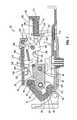
- FIG. 5is a cross-sectional view of the head mechanism taken along section line 5 - 5 of FIG. 2 when the door is in the open position.
- FIG. 6is a bottom view of the head mechanism shown in FIG. 3 when the door is in a closed position.
- FIG. 7is a cross-sectional view of the head mechanism taken along section line 5 - 5 of FIG. 2 when the door is in the closed position.
- FIG. 8is a bottom view of the head mechanism shown in FIG. 3 when the door is in the closed position and a latchbolt of the head mechanism is in a retracted position.
- FIG. 9is a perspective view of a bracket for use with the head mechanism.
- FIG. 10is a front view of a portion of the head mechanism shown in FIG. 2 including a firedog link spaced apart from a deadlock link.
- FIG. 11is a front view of the portion of the head mechanism shown in FIG. 10 without the inner housing and with the firedog link engaging the deadlock link.
- FIG. 12is a cross-sectional view of the portion of the head mechanism taken along section line 12 - 12 of FIG. 11 .
- FIG. 1illustrates an exit device 20 embodying the invention.
- the exit device 20is mounted to a door 24 in, for example, an office building, school, warehouse, factory, or other public building.
- the exit device 20 and all of its internal componentsare substantially symmetrical about a central plane extending through the device 20 such that the exit device 20 may be reversed (e.g., rotated 180 degrees) to mount adjacent to either edge or on either side of the door 24 .
- the illustrated exit device 20includes an elongated housing 28 , a head mechanism 32 , and a pushbar 36 .
- the elongated housing 28or channel, is mounted to the door 24 and supports the pushbar 36 .
- the head mechanism 32is mounted to the door 24 adjacent to the elongated housing 28 and includes a latchbolt 40 extending beyond an edge 44 of the door 24 .
- the latchbolt 40is configured to engage a strike 48 (FIGS. 4 and 6 - 8 ) when in an extended position ( FIGS. 2-7 ) to retain the door 24 in a closed position.
- the pushbar 36is coupled to the head mechanism 32 through the elongated housing 28 to actuate the latchbolt 40 from the extended position to a retracted position ( FIG.
- the pushbar 36may be coupled to the head mechanism 32 and actuate the latchbolt 40 with, for example, a crank-rocker mechanism or a scissor mechanism positioned within the elongated housing 28 .
- other suitable actuatorse.g., a rotatable handle or lever, or the like
- Such arrangementsare known in the art.
- FIGS. 2 and 3illustrate the head mechanism 32 of the exit device 20 in more detail.
- the head mechanism 32includes an outer cover 52 ( FIG. 1 ), an inner housing 56 , and the latchbolt 40 .
- the outer cover 52is coupled to a chassis 60 of the head mechanism 32 to cover and protect the internal components of the head mechanism 32 .
- the inner housing 56is coupled to the chassis 60 within the outer cover 52 to support the latchbolt 40 and other internal components of the head mechanism 32 .
- the outer cover 52is removed from the head mechanism 32 in FIGS. 2 and 3 and the inner housing 56 is removed from the head mechanism 32 in FIG. 3 to facilitate illustration of the internal components of the head mechanism 32 .
- the illustrated latchbolt 40is coupled to the inner housing 56 and extends from the outer cover 52 adjacent to the edge 44 of the door 24 .
- the latchbolt 40includes a bearing 64 surrounding a portion of a pin 68 .
- the pin 68extends through the inner housing 56 such that the latchbolt 40 rotates about the pin 68 relative to the inner housing 56 between the extended position ( FIGS. 2-7 ) and the retracted position ( FIG. 8 ).
- a biasing membere.g., a torsional spring
- a biasing memberis positioned within the latchbolt 40 about a pin 92 to bias the latchbolt 40 toward the extended position.
- the latchbolt 40also includes a generally planar surface 72 and a curved surface 76 .
- the strike 48engages the planar surface 72 to push latchbolt 40 against the bias of the biasing member, rotating the latchbolt 40 about the pin 68 to the retracted position.
- the latchbolt 40is thereby moved out of the way (i.e., clears) the strike 48 so that the door 24 can finish rotating to the closed position.
- the biasing memberbiases the latchbolt 40 back to the extended position.
- the curved surface 76 of the latchbolt 40engages the strike 48 to retain the door 24 in the closed position.
- the head mechanism 32includes a latchbolt link 80 and a pushbar link 84 .
- An end portion of the latchbolt link 80is positioned within a cavity 88 of the latchbolt 40 and supports the hollow pin 92 to couple the latchbolt link 80 to the latchbolt 40 .
- the hollow pin 92allows some relative movement (e.g., rotation) between the latchbolt 40 and the latchbolt link 80 as the latchbolt 40 rotates about the pin 68 .
- the opposite end of the latchbolt link 80is coupled to the pushbar link 84 with a pin 96 .
- the pushbar link 84is in turn coupled to the pushbar 36 ( FIG.
- the head mechanism 32also includes an auxiliary bolt 100 , a deadlock link 104 , a bracket 108 , and a spring 112 .
- the illustrated auxiliary bolt 100includes two sidewalls 116 extending substantially perpendicular from the chassis 60 , a forward wall portion 120 connecting the sidewalls 116 adjacent to the latchbolt 40 , and a rearward wall portion 124 ( FIGS. 5 and 7 ) connecting the sidewalls 116 proximate the deadlock link 104 .
- Each sidewall 116defines two clearance slots 128 , 132 to facilitate coupling the auxiliary bolt 100 to the inner housing 56 .
- the slots 128receive the pin 96 that couples the latchbolt link 80 to the pushbar link 84 to allow the pin 96 , and thereby the latchbolt link 80 and the pushbar link 84 , to move relative to the auxiliary bolt 100 .
- the inner housing 56defines corresponding clearance slots 136 to also allow the latchbolt link 80 and the pushbar link 84 to move relative to the inner housing 56 .
- the slots 132receive a pin 140 that couples the deadlock link 104 and the bracket 108 to the inner housing 56 to allow the pin 140 , and thereby the deadlock link 104 and the bracket 108 , to move relative to the auxiliary bolt 100 .
- the auxiliary bolt 100is movable relative to the inner housing 56 between an extended position ( FIGS. 2-5 ) and a retracted position ( FIGS. 6-8 ). In the illustrated construction, the auxiliary bolt 100 translates between the extended and retracted positions by sliding along the pins 96 , 140 . As shown in FIGS. 5 and 7 , the spring 112 engages the rearward wall portion 124 of the auxiliary bolt 100 to bias the auxiliary bolt 100 toward the extended position (to the left in the figures). When the door 24 is in the open position ( FIGS. 4 and 5 ), the auxiliary bolt 100 is in the extended position such that the rearward wall portion 124 engages the deadlock link 104 , as further discussed below.
- the strike 48engages a ramped surface 144 on each sidewall 116 of the auxiliary bolt 100 proximate the forward wall portion 120 to push the auxiliary bolt 100 against the bias of the spring 112 to the retracted position.
- the strike 48remains in contact with the auxiliary bolt 100 to keep the auxiliary bolt 100 in the retracted position such that the rearward wall portion 124 of the auxiliary bolt 100 is spaced apart from the deadlock link 104 .
- the deadlock link 104includes two leg portions 148 extending generally toward the chassis 60 and two arm portions 152 extending generally toward the latchbolt 40 .
- the deadlock link 104is rotatably coupled to the inner housing 56 by the pin 140 extending through the leg portions 148 such that the deadlock link 104 can rotate relative to the housing 56 .
- the pin 140defines a pivot axis 156 .
- the deadlock link 104also includes a post or pin 160 extending through the arm portions 152 .
- the post 160is configured to engage a surface 164 of the latchbolt link 80 to inhibit movement of the latchbolt 40 to the retracted position, as further described below.
- the post 160may be replaced with other suitable ribs or projections that are configured to engage the latchbolt link 80 .
- the post 160may engage the latchbolt 40 directly to inhibit movement of the latchbolt 40 to the retracted position.
- the illustrated deadlock link 104rotates about the pivot axis 156 between a disengaged position ( FIGS. 4 , 5 , and 8 ) and an engaged position ( FIGS. 6 and 7 ).
- the deadlock link 104In the disengaged position, the deadlock link 104 is oriented such that the post 160 is spaced apart from the surface 164 of the latchbolt link 80 , allowing the latchbolt 40 to move toward the retracted position.
- the deadlock link 104is rotated about the pivot axis 156 toward the disengaged position when the door 24 is in the open position and/or the pushbar 36 is actuated (e.g., when the auxiliary bolt 100 is in the extended position and/or the pushbar link 84 is retracted).
- the deadlock link 104In the engaged position, the deadlock link 104 is oriented such that the post 160 contacts the surface 164 of the latchbolt link 80 ( FIG. 6 ), inhibiting movement of the latchbolt 40 to the retracted position.
- the deadlock link 104is rotated about the pivot axis 156 toward the engaged position when the door 24 is in the closed position (e.g., when the auxiliary bolt 100 is in the retracted position and the pushbar link 84 is not retracted).
- the bracket 108is also coupled to the inner housing 56 with the pin 140 that supports the deadlock link 104 .
- the illustrated bracket 108includes two clearance slots 166 ( FIG. 9 ) to receive the pin 140 and a cylindrical shaft 168 extending from a rear wall 172 of the bracket 108 through an opening 174 in the rearward wall portion 124 of the auxiliary bolt 100 .
- the end of the shaft 168forms two hook-shaped prongs 175 that compress together to facilitate inserting the shaft 168 through the opening 174 .
- the bracket 108also includes two ribs 176 (only one of which is shown) extending inwardly from opposing sidewalls of the bracket 108 toward the shaft 168 . Each rib 176 engages the corresponding leg portion 148 of the deadlock link 104 , as further described below.
- the bracket 108may include a single rib that only engages one leg portion 148 of the deadlock link 104 .
- the bracketmay include a single post or member extending between the sidewalls 180 of the bracket 108 to engage both leg portions 148 of the deadlock link 104 .
- the spring 112is positioned about the shaft 168 between the rear wall 172 of the bracket 108 and the rearward wall portion 124 of the auxiliary bolt 100 .
- the spring 112biases the auxiliary bolt 100 toward the extended position and biases the bracket 108 away from the latchbolt 40 .
- the rearward wall portion 124 of the auxiliary bolt 100engages the leg portions 148 of the deadlock link 104 along a first edge 184
- the ribs 176 of the bracket 108engage the leg portions 148 of the deadlock link 104 along a second edge 188 .
- the auxiliary bolt 100contacts the leg portions 148 of the deadlock link 104 at a first distance A from the pivot axis 156 and the bracket 108 contacts the leg portions 148 of the deadlock link 104 at a second distance B from the pivot axis 156 .
- the first distance Ais substantially larger than the second distance B such that, when both the auxiliary bolt 100 and the bracket 108 are contacting the deadlock link 104 , the deadlock link 104 is rotated (clockwise in FIG. 5 ) by the auxiliary bolt 100 to the disengaged position.
- the rearward wall portion 124 of the auxiliary bolt 100is spaced apart from the deadlock link 104 .
- the deadlock link 104is thereby rotated by the bracket 108 in an opposite direction (counterclockwise in FIG. 7 ) about the pivot axis 156 to the engaged position.
- the door 24is in the open position so that the latchbolt 40 and the auxiliary bolt 100 are in their extended positions.
- both the rearward wall portion 124 of the auxiliary bolt 100 and the ribs 176 of the bracket 108engage the leg portions 148 of the deadlock link 104 , rotating the deadlock link 104 to the disengaged position.
- the post 160 of the deadlock link 104is thereby spaced apart from the surface 164 of the latchbolt link 80 such that the latchbolt 40 is movable to the retracted position.
- the latchbolt 40 and the auxiliary bolt 100move to their retracted positions to clear the strike 48 , allowing the door 24 to rotate to the closed position.
- the door 24is in the closed position so that the latchbolt 40 is in the extended position and the auxiliary bolt 100 is in the retracted position.
- the rearward wall portion 124 of the auxiliary bolt 100is spaced apart from the leg portions 148 of the deadlock link 104 so that only the ribs 176 of the bracket 108 engage the deadlock link 104 .
- the deadlock link 104is rotated about the pivot axis 156 to the engaged position.
- the post 160 of the deadlock link 104contacts the surface 164 of the latchbolt link 80 to inhibit movement of the latchbolt 40 toward the retracted position, thereby retaining the door 24 in the closed position.
- the spring 112is further compressed between the rearward portion 124 of the auxiliary bolt 100 and the rear wall 172 of the bracket 108 when the auxiliary bolt 100 is in the retracted position.
- the biasing force provided by the spring 112 between the ribs 176 of the bracket 108 and the leg portions 148 of the deadlock link 104is therefore increased.
- the amount of force holding the deadlock link 104 in the engaged positionis increased.
- the spring 112will be even further compressed, increasing the biasing force provided by the spring 112 and, thereby, increasing the amount of force holding the deadlock link 104 in the engaged position.
- the deadlock link 104When the door is in the closed position, the deadlock link 104 is moved from the engaged position to the disengaged position by actuating the pushbar 36 . Actuating the pushbar moves the pushbar link 84 from the position shown in FIGS. 6 and 7 to the position shown in FIG. 8 . As the pushbar link 84 slides away from the latchbolt 40 (to the right in FIGS. 6-8 ), ramped surfaces 192 of the pushbar link 84 contact the post 160 of the deadlock link 104 . The pushbar link 84 lifts the post 160 away from the latchbolt link 84 (i.e., from the position shown in FIGS.
- the pushbar link 84pulls the latchbolt link 80 , which pulls the latchbolt 40 to the retracted position. Since the post 160 of the deadlock link 104 is no longer engaging the surface 164 of the latchbolt link 80 , the latchbolt 40 can retract far enough to clear the strike 48 , allowing the door 24 to rotate to the open position. Once the latchbolt 40 is clear of the strike 48 and the pushbar 36 is released, the latchbolt 40 and the auxiliary bolt 100 return to their extended positions ( FIGS. 4 and 5 ) such that the auxiliary bolt 100 holds the deadlock link 104 in the disengaged position until the door 24 is closed again.
- the head mechanism 32also includes a firedog link 196 to help prevent the door 24 from being opened in the event of a fire.
- the illustrated firedog link 196is coupled to the inner housing 56 and supported by the bracket 108 , as further explained below.
- the firedog link 196includes a hooked portion 200 extending through an arcuate slot 204 in the inner housing 56 .
- a fastener 208couples the firedog link 196 to the inner housing 56 .
- the fastener 208rotatably couples the firedog link 196 to the inner housing 56 so that the firedog link 196 can rotate from an unlocked position ( FIG. 10 ) to a locked position ( FIGS. 11 and 12 ).
- FIGS. 10unlocked position
- FIGS. 11 and 12locked position
- the head mechanism 32is shown in elevation, or as it would be mounted on a vertical door, such that gravity biases the firedog link 196 to rotate about the fastener 208 in a counterclockwise direction.
- the hooked portion 200 of the firedog link 196is positioned between the arm portions 152 of the deadlock link 104 , allowing the deadlock link 104 to rotate between the engaged and disengaged positions without interference from the firedog link 196 .
- the hooked portion 200contacts one of the arm portions 152 of the deadlock link 104 , preventing rotation of the deadlock link 104 from the engaged position to the disengaged position.
- the firedog link 196may be slidably coupled to the inner housing 56 using suitable coupling means so that the firedog link 196 slides from the unlocked position to the locked position.
- the bracket 108includes two projections 212 extending through corresponding openings 216 in the inner housing 56 adjacent to the firedog link 196 .
- the projections 212support the firedog link 196 in the unlocked position so that the hooked portion 200 does not engage and prevent movement of the deadlock link 104 .
- the bracket 108is composed of a nylon material such that the bracket 108 melts at relatively high temperatures (e.g., during a fire).
- the bracket 180may be composed of other fusible materials.
- the firedog link 196when the bracket 108 melts, the firedog link 196 is no longer supported by the projections 212 .
- the firedog link 196thereby rotates to the locked position such that the hooked portion 200 of the firedog link 196 slides within the arcuate slot 204 to engage one of the arm portions 152 of the deadlock link 104 .
- the firedog link 196is rotated by gravity, although in other constructions, a spring may be positioned about the fastener 208 to bias the firedog link 196 to the locked position.
- the firedog link 196prevents the deadlock link 104 from moving to the disengaged position (even if a user actuates the pushbar 36 ) to retain the door 24 in the closed position during a fire.
Landscapes
- Business, Economics & Management (AREA)
- Emergency Management (AREA)
- Closing And Opening Devices For Wings, And Checks For Wings (AREA)
- Special Wing (AREA)
Abstract
Description
Claims (24)
Priority Applications (1)
| Application Number | Priority Date | Filing Date | Title |
|---|---|---|---|
| US12/169,388US8146961B2 (en) | 2008-07-08 | 2008-07-08 | Exit device |
Applications Claiming Priority (1)
| Application Number | Priority Date | Filing Date | Title |
|---|---|---|---|
| US12/169,388US8146961B2 (en) | 2008-07-08 | 2008-07-08 | Exit device |
Publications (2)
| Publication Number | Publication Date |
|---|---|
| US20100007154A1 US20100007154A1 (en) | 2010-01-14 |
| US8146961B2true US8146961B2 (en) | 2012-04-03 |
Family
ID=41504495
Family Applications (1)
| Application Number | Title | Priority Date | Filing Date |
|---|---|---|---|
| US12/169,388Active2031-02-01US8146961B2 (en) | 2008-07-08 | 2008-07-08 | Exit device |
Country Status (1)
| Country | Link |
|---|---|
| US (1) | US8146961B2 (en) |
Cited By (8)
| Publication number | Priority date | Publication date | Assignee | Title |
|---|---|---|---|---|
| US20120256428A1 (en)* | 2011-04-07 | 2012-10-11 | Hung-Jen Tien | Stop Device for Door Lock for Panic Exit Door |
| US20130001961A1 (en)* | 2011-06-28 | 2013-01-03 | Chun-Meng Shen | Door Lock with Idle Travel in a Locking State |
| US20140132009A1 (en)* | 2012-11-12 | 2014-05-15 | Stanley Security Solutions Taiwan Ltd. | Latch device for an exit device for a door |
| US20180119456A1 (en)* | 2016-11-03 | 2018-05-03 | Schlage Lock Company Llc | Dual function security/fire locking mechanism for fire rated devices |
| US20190128018A1 (en)* | 2017-10-26 | 2019-05-02 | Schlage Lock Company Llc | Exit device with self-adjusting coupling mechanism |
| USD906084S1 (en)* | 2019-01-28 | 2020-12-29 | Sargent Manufacturing Company | Exit device with status indicator |
| USD906085S1 (en)* | 2019-01-28 | 2020-12-29 | Assa Abloy Access And Egress Hardware Group, Inc. | Exit device with status indicator |
| US11142929B2 (en) | 2018-04-09 | 2021-10-12 | Sargent Manufacturing Company | Exit device |
Families Citing this family (7)
| Publication number | Priority date | Publication date | Assignee | Title |
|---|---|---|---|---|
| US8495836B2 (en)* | 2009-08-27 | 2013-07-30 | Sargent Manufacturing Company | Door hardware drive mechanism with sensor |
| US10174525B2 (en) | 2013-12-30 | 2019-01-08 | Schlage Lock Company Llc | Exit device with over-travel mechanism |
| US10072444B2 (en)* | 2015-05-15 | 2018-09-11 | Schlage Lock Company Llc | Exit device force adjustment mechanisms |
| US11566449B2 (en)* | 2017-11-29 | 2023-01-31 | Hanchett Entry Systems, Inc. | Interchangeable latch assembly for an exit device |
| US20190352937A1 (en) | 2018-05-15 | 2019-11-21 | Schlage Lock Company Llc | Exit device coordination mechanisms |
| US11156025B2 (en)* | 2018-07-05 | 2021-10-26 | Schlage Lock Company Llc | Latchbolt damping module |
| CN112431483B (en)* | 2019-08-26 | 2022-02-22 | 堡笙工业有限公司 | Anti-theft door lock set |
Citations (56)
| Publication number | Priority date | Publication date | Assignee | Title |
|---|---|---|---|---|
| US3705739A (en) | 1971-07-07 | 1972-12-12 | Ilco Corp | Panic lock device |
| US3744832A (en) | 1972-09-05 | 1973-07-10 | R Casey | Fusible door holding device |
| US3777422A (en) | 1971-11-22 | 1973-12-11 | L Janssen | Skylight and safety device |
| US3811717A (en) | 1973-03-01 | 1974-05-21 | Sargent & Co | Latch bolt stop lever for fire door lock sets |
| US4005886A (en) | 1975-12-18 | 1977-02-01 | Door Controls Incorporated | Flush bolt mechanisms |
| US4007954A (en) | 1975-11-10 | 1977-02-15 | Walter Kidde & Company, Inc. | Hospital latch |
| US4015869A (en) | 1975-09-30 | 1977-04-05 | Access Control Systems Pty. Ltd. | Catch mechanism |
| US4099753A (en) | 1977-01-24 | 1978-07-11 | Mckinney Manufacturing Company | Automatic locking mechanism for one of a pair of hinged doors |
| US4145900A (en) | 1977-11-21 | 1979-03-27 | Walter Kidde & Company, Inc. | Lock for fire doors |
| US4161804A (en) | 1977-12-21 | 1979-07-24 | Rixson-Firemark, Inc. | Heat-actuated door latch |
| US4183565A (en) | 1978-08-28 | 1980-01-15 | Norris Industries, Inc. | Latch bolt locking mechanism for fire door locksets |
| USRE30263E (en) | 1974-10-02 | 1980-04-29 | Access Controls System Pty. Ltd. | Catch mechanism |
| US4272111A (en) | 1979-03-26 | 1981-06-09 | Illinois Tool Works Inc. | Safety latch device |
| US4311329A (en) | 1979-11-02 | 1982-01-19 | Scovill Inc. | Panic-type device having fusible section in push rod to avoid unintentional opening of door in event of fire |
| US4333489A (en) | 1978-09-11 | 1982-06-08 | Actionair Equipment Limited | Spring-motor dual-functioning mechanism |
| US4437693A (en) | 1981-05-13 | 1984-03-20 | Von Duprin, Inc. | Thermally responsive latching device and method of modifying a latching device |
| US4453753A (en) | 1982-06-04 | 1984-06-12 | Baldwin Hardware Manufacturing Corporation | Heat responsive door latch handle |
| US4502720A (en) | 1982-06-04 | 1985-03-05 | Baldwin Hardware Manufacturing Corporation | Door latch apparatus |
| US4598939A (en) | 1984-06-08 | 1986-07-08 | Scovill Inc. | Exit device |
| US4709950A (en) | 1984-06-21 | 1987-12-01 | American Device Manufacturing Co. | Crash bar door locking device |
| US4714285A (en) | 1984-03-27 | 1987-12-22 | D.R.I.M. Limited | Fire-break door |
| US4726613A (en) | 1986-03-03 | 1988-02-23 | Best Lock Corporation | Fire safety door latch |
| US4747629A (en) | 1985-05-01 | 1988-05-31 | Emhart Industries, Inc. | Emergency exit lock device |
| US4824150A (en) | 1988-02-29 | 1989-04-25 | Adams Rite Manufacturing Company | Fire responsive safety door assembly |
| US4865367A (en) | 1988-05-09 | 1989-09-12 | Adams Rite Manufacturing Company | Safety door with counterweight locking |
| US4884832A (en) | 1988-09-22 | 1989-12-05 | Rockwood Manufacturing Company | Heat triggered door jamming mechanism |
| US4986583A (en) | 1988-09-26 | 1991-01-22 | Triangle Brass Manufacturing Company | Door-latch opener |
| US5022690A (en) | 1989-09-18 | 1991-06-11 | Adams & Coltrin, Inc. | Quick release latch mechanism |
| US5121950A (en) | 1991-04-23 | 1992-06-16 | The Stanley Works | Heat activated spring loaded locking bolt for hinged doors and door assemblies employing same |
| US5245879A (en) | 1992-05-07 | 1993-09-21 | Mckeon Rolling Steel Door Co., Inc. | Fail-safe fire door release mechanism having automatic reset |
| US5380053A (en) | 1993-07-26 | 1995-01-10 | F. L. Saino Manufacturing Co. | Intumescent fire door lock mechanism |
| US5427420A (en) | 1994-01-10 | 1995-06-27 | Schlage Lock Company | Latchbolt assembly, with fusibly-actuated deadlocking |
| US5464259A (en) | 1993-06-01 | 1995-11-07 | Von Duprin, Inc. | Door latch assembly with meltable fuse mechanism |
| US5492208A (en) | 1994-02-01 | 1996-02-20 | Pemko Manufacturing Company | Intumescent security pin for fire rated doors |
| US5527074A (en) | 1994-10-20 | 1996-06-18 | Yeh; Wen Tien | Fire protection door lock having a heat sensitive safety device |
| US5588686A (en) | 1994-12-05 | 1996-12-31 | Adams Rite Manufacturing Company | Temperature responsive mechanism for controllably deadlocking a door to a door frame |
| US5619824A (en) | 1995-06-12 | 1997-04-15 | Steelcase, Inc. | Heat releaseable ceiling support |
| US5638639A (en) | 1994-04-28 | 1997-06-17 | Won-Door Corporation | Emergency door with retractable nose piece, interiorly mounted operating hardware, and hinge supports |
| US5673949A (en) | 1995-12-26 | 1997-10-07 | Von Duprin, Inc. | Push pad trigger release for a vertical rod exit device |
| US5688002A (en) | 1994-12-05 | 1997-11-18 | Adams Rite Manufacturing Co. | Concealed rod or cable surface latching exit device |
| US5690371A (en) | 1994-11-21 | 1997-11-25 | Schlage Lock Company | Fused spring latch |
| US5782509A (en) | 1997-02-18 | 1998-07-21 | Adams Rite Manufacturing Co. | Bolt closure maintenance for fire-degraded latching assembly |
| US5839766A (en) | 1993-11-17 | 1998-11-24 | Iannuzzi; Nelson A. | Door control system and release mechanism |
| US5890752A (en) | 1996-12-02 | 1999-04-06 | Lin; Chin-Tien | Push-type lock for fire-blocking doors |
| US6009732A (en) | 1998-04-07 | 2000-01-04 | Detex Corporation | Panic exit device |
| US6106032A (en) | 1995-09-20 | 2000-08-22 | Festo Kg | Pneumatic door lock |
| US6131338A (en) | 1997-09-24 | 2000-10-17 | Detex Corporation | Removable mullion assembly |
| US6283513B1 (en) | 1999-05-07 | 2001-09-04 | Wen Tien Yeh | Locking device for a two-door unit of swinging type |
| US6581423B2 (en) | 2001-11-01 | 2003-06-24 | Ching-Tien Lin | Door lock |
| US6615544B1 (en) | 2000-06-21 | 2003-09-09 | Nystrom, Inc. | Fire-resistant door |
| US6725602B1 (en) | 2003-01-21 | 2004-04-27 | Mcwilliams William A. | Automatically extendable astragal system |
| US6820905B1 (en) | 2000-07-26 | 2004-11-23 | Detex Corporation | Vertical panic exit device |
| US6854773B2 (en) | 2002-12-27 | 2005-02-15 | Ching-Tien Lin | Fire door lock mechanism |
| US6886871B1 (en) | 2003-12-01 | 2005-05-03 | Shen Mu-Lin | Fireproof cover for a tubular lock |
| US7044510B2 (en) | 2002-12-27 | 2006-05-16 | Ching-Tien Lin | Fire door lock mechanism |
| US7070210B2 (en)* | 2003-03-17 | 2006-07-04 | Ching-Tien Lin | Fire-blocking door lock structure |
- 2008
- 2008-07-08USUS12/169,388patent/US8146961B2/enactiveActive
Patent Citations (60)
| Publication number | Priority date | Publication date | Assignee | Title |
|---|---|---|---|---|
| US3705739A (en) | 1971-07-07 | 1972-12-12 | Ilco Corp | Panic lock device |
| US3777422A (en) | 1971-11-22 | 1973-12-11 | L Janssen | Skylight and safety device |
| US3744832A (en) | 1972-09-05 | 1973-07-10 | R Casey | Fusible door holding device |
| US3811717A (en) | 1973-03-01 | 1974-05-21 | Sargent & Co | Latch bolt stop lever for fire door lock sets |
| USRE30263E (en) | 1974-10-02 | 1980-04-29 | Access Controls System Pty. Ltd. | Catch mechanism |
| US4015869A (en) | 1975-09-30 | 1977-04-05 | Access Control Systems Pty. Ltd. | Catch mechanism |
| US4007954A (en) | 1975-11-10 | 1977-02-15 | Walter Kidde & Company, Inc. | Hospital latch |
| US4005886A (en) | 1975-12-18 | 1977-02-01 | Door Controls Incorporated | Flush bolt mechanisms |
| US4099753A (en) | 1977-01-24 | 1978-07-11 | Mckinney Manufacturing Company | Automatic locking mechanism for one of a pair of hinged doors |
| US4145900A (en) | 1977-11-21 | 1979-03-27 | Walter Kidde & Company, Inc. | Lock for fire doors |
| US4161804A (en) | 1977-12-21 | 1979-07-24 | Rixson-Firemark, Inc. | Heat-actuated door latch |
| US4183565A (en) | 1978-08-28 | 1980-01-15 | Norris Industries, Inc. | Latch bolt locking mechanism for fire door locksets |
| US4333489A (en) | 1978-09-11 | 1982-06-08 | Actionair Equipment Limited | Spring-motor dual-functioning mechanism |
| US4272111A (en) | 1979-03-26 | 1981-06-09 | Illinois Tool Works Inc. | Safety latch device |
| US4311329A (en) | 1979-11-02 | 1982-01-19 | Scovill Inc. | Panic-type device having fusible section in push rod to avoid unintentional opening of door in event of fire |
| US4437693A (en) | 1981-05-13 | 1984-03-20 | Von Duprin, Inc. | Thermally responsive latching device and method of modifying a latching device |
| US4453753A (en) | 1982-06-04 | 1984-06-12 | Baldwin Hardware Manufacturing Corporation | Heat responsive door latch handle |
| US4502720A (en) | 1982-06-04 | 1985-03-05 | Baldwin Hardware Manufacturing Corporation | Door latch apparatus |
| US4714285A (en) | 1984-03-27 | 1987-12-22 | D.R.I.M. Limited | Fire-break door |
| US4598939A (en) | 1984-06-08 | 1986-07-08 | Scovill Inc. | Exit device |
| US4709950A (en) | 1984-06-21 | 1987-12-01 | American Device Manufacturing Co. | Crash bar door locking device |
| US4747629A (en) | 1985-05-01 | 1988-05-31 | Emhart Industries, Inc. | Emergency exit lock device |
| US4726613A (en) | 1986-03-03 | 1988-02-23 | Best Lock Corporation | Fire safety door latch |
| US4824150A (en) | 1988-02-29 | 1989-04-25 | Adams Rite Manufacturing Company | Fire responsive safety door assembly |
| US4865367A (en) | 1988-05-09 | 1989-09-12 | Adams Rite Manufacturing Company | Safety door with counterweight locking |
| US4884832A (en) | 1988-09-22 | 1989-12-05 | Rockwood Manufacturing Company | Heat triggered door jamming mechanism |
| US4986583A (en) | 1988-09-26 | 1991-01-22 | Triangle Brass Manufacturing Company | Door-latch opener |
| US5022690A (en) | 1989-09-18 | 1991-06-11 | Adams & Coltrin, Inc. | Quick release latch mechanism |
| US5121950A (en) | 1991-04-23 | 1992-06-16 | The Stanley Works | Heat activated spring loaded locking bolt for hinged doors and door assemblies employing same |
| US5245879A (en) | 1992-05-07 | 1993-09-21 | Mckeon Rolling Steel Door Co., Inc. | Fail-safe fire door release mechanism having automatic reset |
| US5464259A (en) | 1993-06-01 | 1995-11-07 | Von Duprin, Inc. | Door latch assembly with meltable fuse mechanism |
| US5380053A (en) | 1993-07-26 | 1995-01-10 | F. L. Saino Manufacturing Co. | Intumescent fire door lock mechanism |
| US5839766A (en) | 1993-11-17 | 1998-11-24 | Iannuzzi; Nelson A. | Door control system and release mechanism |
| US5427420A (en) | 1994-01-10 | 1995-06-27 | Schlage Lock Company | Latchbolt assembly, with fusibly-actuated deadlocking |
| US5492208A (en) | 1994-02-01 | 1996-02-20 | Pemko Manufacturing Company | Intumescent security pin for fire rated doors |
| US5638639A (en) | 1994-04-28 | 1997-06-17 | Won-Door Corporation | Emergency door with retractable nose piece, interiorly mounted operating hardware, and hinge supports |
| US5527074A (en) | 1994-10-20 | 1996-06-18 | Yeh; Wen Tien | Fire protection door lock having a heat sensitive safety device |
| US5690371A (en) | 1994-11-21 | 1997-11-25 | Schlage Lock Company | Fused spring latch |
| US5588686A (en) | 1994-12-05 | 1996-12-31 | Adams Rite Manufacturing Company | Temperature responsive mechanism for controllably deadlocking a door to a door frame |
| US5688002A (en) | 1994-12-05 | 1997-11-18 | Adams Rite Manufacturing Co. | Concealed rod or cable surface latching exit device |
| US5864936A (en) | 1994-12-05 | 1999-02-02 | Adams Rite Manufacturing Co. | Method of providing and installing a door latching structure |
| US5619824A (en) | 1995-06-12 | 1997-04-15 | Steelcase, Inc. | Heat releaseable ceiling support |
| US6106032A (en) | 1995-09-20 | 2000-08-22 | Festo Kg | Pneumatic door lock |
| US5673949A (en) | 1995-12-26 | 1997-10-07 | Von Duprin, Inc. | Push pad trigger release for a vertical rod exit device |
| US5890752A (en) | 1996-12-02 | 1999-04-06 | Lin; Chin-Tien | Push-type lock for fire-blocking doors |
| US5782509A (en) | 1997-02-18 | 1998-07-21 | Adams Rite Manufacturing Co. | Bolt closure maintenance for fire-degraded latching assembly |
| US6131338A (en) | 1997-09-24 | 2000-10-17 | Detex Corporation | Removable mullion assembly |
| US6009732A (en) | 1998-04-07 | 2000-01-04 | Detex Corporation | Panic exit device |
| US6205825B1 (en)* | 1998-04-07 | 2001-03-27 | Detex Corporation | Panic exit device mounting plate |
| US6532777B2 (en) | 1998-04-07 | 2003-03-18 | Detex Corporation | Panic exit device mounting plate |
| US6283513B1 (en) | 1999-05-07 | 2001-09-04 | Wen Tien Yeh | Locking device for a two-door unit of swinging type |
| US6615544B1 (en) | 2000-06-21 | 2003-09-09 | Nystrom, Inc. | Fire-resistant door |
| US7028431B2 (en) | 2000-06-21 | 2006-04-18 | Nystrom, Inc. | Fire-resistant door |
| US6820905B1 (en) | 2000-07-26 | 2004-11-23 | Detex Corporation | Vertical panic exit device |
| US6581423B2 (en) | 2001-11-01 | 2003-06-24 | Ching-Tien Lin | Door lock |
| US6854773B2 (en) | 2002-12-27 | 2005-02-15 | Ching-Tien Lin | Fire door lock mechanism |
| US7044510B2 (en) | 2002-12-27 | 2006-05-16 | Ching-Tien Lin | Fire door lock mechanism |
| US6725602B1 (en) | 2003-01-21 | 2004-04-27 | Mcwilliams William A. | Automatically extendable astragal system |
| US7070210B2 (en)* | 2003-03-17 | 2006-07-04 | Ching-Tien Lin | Fire-blocking door lock structure |
| US6886871B1 (en) | 2003-12-01 | 2005-05-03 | Shen Mu-Lin | Fireproof cover for a tubular lock |
Cited By (17)
| Publication number | Priority date | Publication date | Assignee | Title |
|---|---|---|---|---|
| US20120256428A1 (en)* | 2011-04-07 | 2012-10-11 | Hung-Jen Tien | Stop Device for Door Lock for Panic Exit Door |
| US8544897B2 (en)* | 2011-04-07 | 2013-10-01 | I-Tek Metal Mfg. Co., Ltd. | Stop device for door lock for panic exit door |
| US20130001961A1 (en)* | 2011-06-28 | 2013-01-03 | Chun-Meng Shen | Door Lock with Idle Travel in a Locking State |
| US8528946B2 (en)* | 2011-06-28 | 2013-09-10 | I-Tek Metal Mfg. Co., Ltd. | Door lock with idle travel in a locking state |
| US20140132009A1 (en)* | 2012-11-12 | 2014-05-15 | Stanley Security Solutions Taiwan Ltd. | Latch device for an exit device for a door |
| US12234673B2 (en) | 2016-11-03 | 2025-02-25 | Schlage Lock Company Llc | Dual function security/fire locking mechanism for fire rated devices |
| US10577832B2 (en)* | 2016-11-03 | 2020-03-03 | Schlage Lock Company Llc | Dual function security/fire locking mechanism for fire rated devices |
| US11692373B2 (en) | 2016-11-03 | 2023-07-04 | Schlage Lock Company Llc | Dual function security/fire locking mechanism for fire rated devices |
| US11118377B2 (en) | 2016-11-03 | 2021-09-14 | Schlage Lock Company Llc | Dual function security/fire locking mechanism for fire rated devices |
| EP4209648A1 (en)* | 2016-11-03 | 2023-07-12 | Schlage Lock Company LLC | Dual function security/fire locking mechanism for fire rated devices |
| US20180119456A1 (en)* | 2016-11-03 | 2018-05-03 | Schlage Lock Company Llc | Dual function security/fire locking mechanism for fire rated devices |
| US20190128018A1 (en)* | 2017-10-26 | 2019-05-02 | Schlage Lock Company Llc | Exit device with self-adjusting coupling mechanism |
| US12435540B2 (en)* | 2017-10-26 | 2025-10-07 | Schlage Lock Company Llc | Exit device with self-adjusting coupling mechanism |
| US11572712B2 (en) | 2018-04-09 | 2023-02-07 | Sargent Manufacturing Company | Exit device |
| US11142929B2 (en) | 2018-04-09 | 2021-10-12 | Sargent Manufacturing Company | Exit device |
| USD906085S1 (en)* | 2019-01-28 | 2020-12-29 | Assa Abloy Access And Egress Hardware Group, Inc. | Exit device with status indicator |
| USD906084S1 (en)* | 2019-01-28 | 2020-12-29 | Sargent Manufacturing Company | Exit device with status indicator |
Also Published As
| Publication number | Publication date |
|---|---|
| US20100007154A1 (en) | 2010-01-14 |
Similar Documents
| Publication | Publication Date | Title |
|---|---|---|
| US8146961B2 (en) | Exit device | |
| US7832777B2 (en) | Door lock assembly | |
| US6578888B1 (en) | Mortise lock with automatic deadbolt | |
| US20240141699A1 (en) | Dual function security/fire locking mechanism for fire rated devices | |
| US8966947B2 (en) | Latches for gates and doors | |
| EP3423652B1 (en) | Latch arrangement having a handle | |
| US20100032966A1 (en) | Gate latch device | |
| US20060266088A1 (en) | Mortise lock having double locking function | |
| CA2647081C (en) | Latchbolt for a door lock assembly | |
| US11319728B2 (en) | True indicating automated sash lock | |
| US7591494B2 (en) | Window lock assembly | |
| KR101467285B1 (en) | Locking assembly for latch bolt | |
| KR101663162B1 (en) | Door Lock having Rotatable Latch Bolt | |
| JP4823874B2 (en) | Electric lock | |
| JP4445416B2 (en) | sliding door | |
| US7134699B1 (en) | Locking rotary latch | |
| EP2592210B1 (en) | Locking assembly for windows or doors | |
| US6196035B1 (en) | Door lock assembly having an automatically actuated latch mechanism | |
| US11781346B2 (en) | Latch structure | |
| JPH0542211Y2 (en) | ||
| JP4346803B2 (en) | Surface guard guard lock. | |
| JP4879721B2 (en) | Door locking device | |
| JPH0241255Y2 (en) | ||
| KR200153744Y1 (en) | A locking device of front door. | |
| JP2593403Y2 (en) | Guard arm device |
Legal Events
| Date | Code | Title | Description |
|---|---|---|---|
| AS | Assignment | Owner name:VON DUPRIN, INC., INDIANA Free format text:ASSIGNMENT OF ASSIGNORS INTEREST;ASSIGNOR:SCHACHT, DAVID M.;REEL/FRAME:021218/0047 Effective date:20080701 | |
| STCF | Information on status: patent grant | Free format text:PATENTED CASE | |
| AS | Assignment | Owner name:VON DUPRIN LLC, INDIANA Free format text:CHANGE OF NAME;ASSIGNOR:VON DUPRIN, INC.;REEL/FRAME:030954/0346 Effective date:20040219 | |
| AS | Assignment | Owner name:SCHLAGE LOCK COMPANY LLC, INDIANA Free format text:ASSIGNMENT OF ASSIGNORS INTEREST;ASSIGNOR:VON DUPRIN LLC;REEL/FRAME:031074/0596 Effective date:20130815 | |
| AS | Assignment | Owner name:VON DUPRIN LLC, INDIANA Free format text:CORRECTIVE ASSIGNMENT TO CORRECT THE ASSIGNEE FROM SCHLAGE LOCK COMPANY LLC TO VON DUPRIN LLC PREVIOUSLY RECORDED ON REEL 031074 FRAME 0596. ASSIGNOR(S) HEREBY CONFIRMS THE ASSIGNMENT;ASSIGNOR:VON DUPRIN LLC;REEL/FRAME:031483/0629 Effective date:20130815 | |
| AS | Assignment | Owner name:JPMORGAN CHASE BANK, N.A., AS ADMINISTRATIVE AGENT Free format text:SECURITY AGREEMENT;ASSIGNOR:SCHLAGE LOCK COMPANY LLC;REEL/FRAME:031831/0091 Effective date:20131126 | |
| AS | Assignment | Owner name:JPMORGAN CHASE BANK, N.A., AS ADMINISTRATIVE AGENT Free format text:SECURITY AGREEMENT;ASSIGNOR:SCHLAGE LOCK COMPANY LLC;REEL/FRAME:034173/0001 Effective date:20141015 | |
| FPAY | Fee payment | Year of fee payment:4 | |
| MAFP | Maintenance fee payment | Free format text:PAYMENT OF MAINTENANCE FEE, 8TH YEAR, LARGE ENTITY (ORIGINAL EVENT CODE: M1552); ENTITY STATUS OF PATENT OWNER: LARGE ENTITY Year of fee payment:8 | |
| MAFP | Maintenance fee payment | Free format text:PAYMENT OF MAINTENANCE FEE, 12TH YEAR, LARGE ENTITY (ORIGINAL EVENT CODE: M1553); ENTITY STATUS OF PATENT OWNER: LARGE ENTITY Year of fee payment:12 |