US8146687B1 - Polycrystalline diamond compact including at least one thermally-stable polycrystalline diamond body and applications therefor - Google Patents
Polycrystalline diamond compact including at least one thermally-stable polycrystalline diamond body and applications thereforDownload PDFInfo
- Publication number
- US8146687B1 US8146687B1US13/149,137US201113149137AUS8146687B1US 8146687 B1US8146687 B1US 8146687B1US 201113149137 AUS201113149137 AUS 201113149137AUS 8146687 B1US8146687 B1US 8146687B1
- Authority
- US
- United States
- Prior art keywords
- polycrystalline diamond
- thermally
- substrate
- stable
- barrier
- Prior art date
- Legal status (The legal status is an assumption and is not a legal conclusion. Google has not performed a legal analysis and makes no representation as to the accuracy of the status listed.)
- Expired - Fee Related
Links
Images


Classifications
- E—FIXED CONSTRUCTIONS
- E21—EARTH OR ROCK DRILLING; MINING
- E21B—EARTH OR ROCK DRILLING; OBTAINING OIL, GAS, WATER, SOLUBLE OR MELTABLE MATERIALS OR A SLURRY OF MINERALS FROM WELLS
- E21B10/00—Drill bits
- E21B10/46—Drill bits characterised by wear resisting parts, e.g. diamond inserts
- E21B10/56—Button-type inserts
- E21B10/567—Button-type inserts with preformed cutting elements mounted on a distinct support, e.g. polycrystalline inserts
- B—PERFORMING OPERATIONS; TRANSPORTING
- B01—PHYSICAL OR CHEMICAL PROCESSES OR APPARATUS IN GENERAL
- B01J—CHEMICAL OR PHYSICAL PROCESSES, e.g. CATALYSIS OR COLLOID CHEMISTRY; THEIR RELEVANT APPARATUS
- B01J3/00—Processes of utilising sub-atmospheric or super-atmospheric pressure to effect chemical or physical change of matter; Apparatus therefor
- B01J3/06—Processes using ultra-high pressure, e.g. for the formation of diamonds; Apparatus therefor, e.g. moulds or dies
- B01J3/062—Processes using ultra-high pressure, e.g. for the formation of diamonds; Apparatus therefor, e.g. moulds or dies characterised by the composition of the materials to be processed
- E—FIXED CONSTRUCTIONS
- E21—EARTH OR ROCK DRILLING; MINING
- E21B—EARTH OR ROCK DRILLING; OBTAINING OIL, GAS, WATER, SOLUBLE OR MELTABLE MATERIALS OR A SLURRY OF MINERALS FROM WELLS
- E21B10/00—Drill bits
- E21B10/46—Drill bits characterised by wear resisting parts, e.g. diamond inserts
- E21B10/56—Button-type inserts
- E21B10/567—Button-type inserts with preformed cutting elements mounted on a distinct support, e.g. polycrystalline inserts
- E21B10/573—Button-type inserts with preformed cutting elements mounted on a distinct support, e.g. polycrystalline inserts characterised by support details, e.g. the substrate construction or the interface between the substrate and the cutting element
- E21B10/5735—Interface between the substrate and the cutting element
- B—PERFORMING OPERATIONS; TRANSPORTING
- B01—PHYSICAL OR CHEMICAL PROCESSES OR APPARATUS IN GENERAL
- B01J—CHEMICAL OR PHYSICAL PROCESSES, e.g. CATALYSIS OR COLLOID CHEMISTRY; THEIR RELEVANT APPARATUS
- B01J2203/00—Processes utilising sub- or super atmospheric pressure
- B01J2203/06—High pressure synthesis
- B01J2203/0605—Composition of the material to be processed
- B01J2203/062—Diamond
- B—PERFORMING OPERATIONS; TRANSPORTING
- B01—PHYSICAL OR CHEMICAL PROCESSES OR APPARATUS IN GENERAL
- B01J—CHEMICAL OR PHYSICAL PROCESSES, e.g. CATALYSIS OR COLLOID CHEMISTRY; THEIR RELEVANT APPARATUS
- B01J2203/00—Processes utilising sub- or super atmospheric pressure
- B01J2203/06—High pressure synthesis
- B01J2203/065—Composition of the material produced
- B01J2203/0655—Diamond
Definitions
- PDCswear-resistant, polycrystalline diamond compacts
- drilling toolse.g., cutting elements, gage trimmers, etc.
- machining equipmente.g., machining equipment, bearing apparatuses, wire-drawing machinery, and in other mechanical apparatuses.
- a PDC cutting elementtypically includes a superabrasive diamond layer commonly known as a diamond table.
- the diamond tableis formed and bonded to a substrate using a high-pressure/high-temperature (“HPHT”) process.
- HPHThigh-pressure/high-temperature
- the PDC cutting elementmay be brazed directly into a preformed pocket, socket, or other receptacle formed in a bit body.
- the substratemay often be brazed or otherwise joined to an attachment member, such as a cylindrical backing.
- a rotary drill bittypically includes a number of PDC cutting elements affixed to the bit body.
- a stud carrying the PDCmay be used as a PDC cutting element when mounted to a bit body of a rotary drill bit by press-fitting, brazing, or otherwise securing the stud into a receptacle formed in the bit body.
- PDCsare normally fabricated by placing a cemented-carbide substrate into a container or cartridge with a volume of diamond particles positioned on a surface of the cemented-carbide substrate. A number of such cartridges may be loaded into an HPHT press. The substrate(s) and volume(s) of diamond particles are then processed under HPHT conditions in the presence of a catalyst material that causes the diamond particles to bond to one another to form a matrix of bonded diamond grains defining a polycrystalline diamond (“PCD”) table.
- the catalyst materialis often a metal-solvent catalyst (e.g., cobalt, nickel, iron, or alloys thereof) that is used for promoting intergrowth of the diamond particles.
- a constituent of the cemented-carbide substratesuch as cobalt from a cobalt-cemented tungsten carbide substrate, liquefies and sweeps from a region adjacent to the volume of diamond particles into interstitial regions between the diamond particles during the HPHT process.
- the cobaltacts as a catalyst to promote intergrowth between the diamond particles, which results in formation of a matrix of bonded diamond grains having diamond-to-diamond bonding therebetween, with interstitial regions between the bonded diamond grains being occupied by the solvent catalyst.
- the presence of the solvent catalyst in the PCD tableis believed to reduce the thermal stability of the PCD table at elevated temperatures.
- the difference in thermal expansion coefficient between the diamond grains and the solvent catalystis believed to lead to chipping or cracking of the PCD table during drilling or cutting operations, which consequently can degrade the mechanical properties of the PCD table or cause failure.
- some of the diamond grainscan undergo a chemical breakdown or back-conversion to graphite via interaction with the solvent catalyst.
- portions of diamond grainsmay transform to carbon monoxide, carbon dioxide, graphite, or combinations thereof, causing degradation of the mechanical properties of the PCD table.
- a sintered PCD tablemay be separately formed and then leached to remove the solvent catalyst from interstitial regions between bonded diamond grains.
- the leached PCD tablemay be simultaneously HPHT bonded to a cemented-carbide substrate and infiltrated with a non-catalyst material, such as silicon, in a separate HPHT process.
- the siliconmay infiltrate the interstitial regions of the leached PCD table from which the solvent catalyst has been leached and react with the diamond grains to form silicon carbide.
- Embodiments of the inventionrelate to PDCs including a barrier receptacle that holds a thermally-stable PCD body at least partially within a substrate and functions as a barrier to prevent metal-solvent catalyst from interacting with the thermally-stable PCD body during manufacture and/or use thereof.
- a PDCcomprises a substrate including a substrate recess formed therein, a barrier receptacle defining a receptacle recess, and a thermally-stable PCD body including an upper surface, a back surface, and at least one lateral surface.
- the barrier receptacleis received by the substrate recess.
- the thermally-stable PCD bodyis at least partially received by the receptacle recess.
- FIG. 1Ais an isometric view of an embodiment of a PDC including a thermally-stable PCD body held in a barrier receptacle that is bonded to a substrate.
- FIG. 1Bis a cross-sectional view of the PDC shown in FIG. 1A .
- FIG. 1Cis an exploded cross-sectional view of the PDC shown in FIG. 1B .
- FIG. 2is an exploded cross-sectional view of an assembly to be HPHT processed in order to form the PDC shown in FIGS. 1A-1C according to an embodiment of a method.
- FIG. 3is a cross-sectional view of the assembly shown in FIG. 2 .
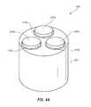
- FIG. 4Ais an isometric view of an embodiment of a PDC that includes a plurality of thermally-stable PCD bodies.
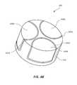
- FIG. 4Bis an isometric view of an embodiment of a PDC that includes a plurality of thermally-stable PCD bodies.
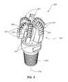
- FIG. 5is an isometric view of an embodiment of a rotary drill bit that may employ one or more of the disclosed PDC embodiments.
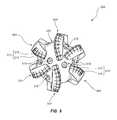
- FIG. 6is a top elevation view of the rotary drill bit shown in FIG. 5 .
- Embodiments of the inventionrelate to PDCs including a barrier receptacle that holds thermally-stable PCD body at least partially within a substrate and functions as a barrier to prevent interaction of metal-solvent catalyst with the thermally-stable PCD body during manufacture and/or use thereof, and methods of fabricating such PDCs.
- the disclosed PDCsmay be used in a variety of applications, such as rotary drill bits, machining equipment, and other articles and apparatuses.
- FIGS. 1A-1Care isometric, cross-sectional, and exploded cross-sectional views, respectively, of an embodiment of a PDC 100 .
- the PDC 100includes a substrate 102 having a substrate recess 104 ( FIGS. 1B and 1C ) formed therein.
- the substrate recess 104( FIGS. 1B and 1C ) is defined by at least one sidewall surface 106 ( FIG. 1C ) and a base surface 108 ( FIG. 1C ).
- the substrate 102may include, without limitation, cemented carbides, such as tungsten carbide, titanium carbide, chromium carbide, niobium carbide, tantalum carbide, vanadium carbide, or combinations thereof cemented with iron, nickel, cobalt, or alloys thereof.
- cemented carbidessuch as tungsten carbide, titanium carbide, chromium carbide, niobium carbide, tantalum carbide, vanadium carbide, or combinations thereof cemented with iron, nickel, cobalt, or alloys thereof.
- the substrate 102comprises cobalt-cemented tungsten carbide.
- the PDC 100further includes a barrier receptacle 110 received by the substrate recess 104 ( FIGS. 1B and 1C ).
- a periphery 112 ( FIG. 1C ) of the barrier receptacle 110is HPHT bonded to the at least one sidewall surface 106 ( FIG. 1C ) and the base surface 108 ( FIG. 1C ) of the substrate 102 defining the substrate recess 104 ( FIGS. 1B and 1C ).
- the barrier receptacle 110includes at least one sidewall surface 114 ( FIG. 1C ) and a base surface 116 ( FIG. 1C ) defining a receptacle recess 118 ( FIG. 1C ).
- the barrier receptacle 110may comprise a material that restricts migration of one or more constituents from the substrate 102 substantially into a thermally-stable PCD body 120 during manufacture and/or use of the PDC 100 .
- the barrier receptaclemay comprise a refractory metal or alloy (e.g., tungsten, zirconium, niobium, vanadium, molybdenum, tantalum, or alloys thereof) or if compatible with the processing temperature steel, brass, an aluminum alloy, or other suitable material.
- the barrier receptacle 110may be formed in the shape of a cylindrical cup or other geometry from a sheet made from tungsten, zirconium, niobium, vanadium, molybdenum, tantalum, or alloys thereof.
- the barrier receptacle 110may exhibit a thickness of about 0.00039 mm to about 0.50 mm.
- the barrier receptacle 110functions as a barrier that helps limit metal-solvent catalyst present in the substrate 102 (e.g., cobalt in a cobalt-cemented tungsten carbide substrate) from interacting with the thermally-stable PCD body 120 received by the barrier receptacle 110 during manufacture and/or use of the PDC 100 .
- the barrier receptacle 110may also be metallurgically bonded to the thermally-stable PCD body 120 and the substrate 102 .
- the thermally-stable PCD body 120is at least partially received by the receptacle recess 118 ( FIG. 1C ) of the barrier receptacle 110 .
- the thermally-stable PCD body 120includes a working upper surface 122 , an opposing back surface 124 ( FIGS. 1B and 1C ), and at least one lateral surface 126 extending therebetween. It should be noted that at least a portion of the at least one lateral surface 126 may also function as a working surface that contacts a subterranean formation during drilling.
- the thermally-stable PCD body 120projects from the receptacle recess 118 ( FIG.
- the thermally-stable PCD body 120has a generally disc-shaped geometry, the configuration of the thermally-stable PCD body 120 may exhibit other selected noncircular configurations suitable for particular applications.
- the thermally-stable PCD body 120may include a chamfer.
- the substrate 102includes a chamfer 128 configured so that the at least one lateral surface 126 and upper surface 122 may reliably contact a subterranean formation during drilling operations.
- the substrate 102may not include the chamfer 128 and the thermally-stable PCD body 120 may project outwardly a sufficient distance from the barrier receptacle 110 .
- the thermally-stable PCD body 120includes a plurality of bonded diamond grains exhibiting diamond-to-diamond bonding therebetween, with the bonded diamond grains defining a plurality of interstitial regions.
- the thermally-stable PCD body 120is an at least partially leached PCD body in which metal-solvent catalyst used in the sintering process to form it has been leached therefrom so that the interstitial regions are substantially free of metal-solvent catalyst.
- residual amounts of the metal-solvent catalystmay be present in the thermally-stable PCD body 120 even after leaching.
- the thermal stability of the thermally-stable PCD body 120is enhanced compared to a PCD body in which the metal-solvent catalyst has not been removed.
- the interstitial regionsinclude silicon carbide, cobalt carbide, a mixed carbide of cobalt and silicon, a cobalt-silicon alloy (e.g., a cobalt silicide), or combinations of the foregoing disposed therein.
- the interstitial regionsinclude a nonmetallic catalyst, such as one or more alkali metal carbonates, one or more alkaline earth metal carbonates, one or more alkaline earth metal hydroxides, one or more alkaline earth metal hydroxides, phosphorous, sulfur, or combinations of the foregoing disposed therein.
- the thermally-stable PCD body 120may be fabricated from any of the PDC bodies manufactured using a nonmetallic carbonate catalyst disclosed in U.S. patent application Ser. No. 12/185,457, the disclosure of which is incorporated herein, in its entirety, by this reference.
- the thermally-stable PCD body 120 shown in FIGS. 1A-1Cmay be fabricated by subjecting a plurality of diamond particles to an HPHT sintering process in the presence of a metal-solvent catalyst (e.g., cobalt, nickel, iron, or alloys thereof) to facilitate intergrowth between the diamond particles and form a PCD body comprised of bonded diamond grains that exhibit diamond-to-diamond bonding therebetween.
- a metal-solvent catalyste.g., cobalt, nickel, iron, or alloys thereof
- the metal-solvent catalystmay be mixed with the diamond particles, infiltrated from a metal-solvent catalyst foil or powder adjacent to the diamond particles, infiltrated from a metal-solvent catalyst present in a cemented-carbide substrate, or combinations of the foregoing.
- the bonded diamond grains, so-formed by HPHT sintering the diamond particlesdefine interstitial regions, with the metal-solvent catalyst disposed within the interstitial regions.
- the diamond particlesmay exhibit a single-mode diamond particle size distribution, or a bimodal or greater diamond particle size distribution.
- the as-sintered PCD bodymay be leached by immersion in an acid, such as aqua regia, nitric acid, hydrofluoric acid, or subjected to another suitable process to remove at least a portion of the metal-solvent catalyst from the interstitial regions of the PCD body and form an at least partially leached PCD body.
- an acidsuch as aqua regia, nitric acid, hydrofluoric acid
- the as-sintered PCD bodymay be immersed in the acid for about a few hours to about 7 days (e.g., about 1, 3, 5, or 7 days) or for a few weeks (e.g., about 4 weeks) depending on the process employed.
- the infiltrated metal-solvent catalystwhen the metal-solvent catalyst is infiltrated into the diamond particles from a cemented tungsten carbide substrate including tungsten carbide particles cemented with a metal-solvent catalyst (e.g., cobalt, nickel, iron, or alloys thereof), the infiltrated metal-solvent catalyst may carry tungsten and/or tungsten carbide therewith and the as-sintered PCD body may include such tungsten and/or tungsten carbide therein disposed interstitially between bonded diamond grains.
- the tungsten and/or tungsten carbidemay be at least partially removed by the selected leaching process or may be relatively unaffected by the selected leaching process.
- the at least partially leached PCD body so-formedmay be infiltrated with silicon or a silicon-cobalt alloy.
- the interstitial regions of the at least partially leached PCD bodymay be filled with silicon carbide, cobalt carbide, a mixed carbide of cobalt and silicon, a silicon-cobalt alloy (e.g., a cobalt silicide), or combinations of the foregoing.
- the thermally-stable PCD body 120may be subjected to a shaping process, such as grinding or lapping, to tailor the geometry thereof, as desired, for a particular application. For example, a chamfer or a radius may be formed on an edge of the as-sintered PCD body.
- a machining processsuch as electro-discharge machining.
- the plurality of diamond particles sintered to form the thermally-stable PCD body 120may exhibit one or more selected sizes.
- the one or more selected sizesmay be determined, for example, by passing the diamond particles through one or more sizing sieves or by any other method.
- the plurality of diamond particlesmay include a relatively larger size and at least one relatively smaller size.
- the phrases “relatively larger” and “relatively smaller”refer to particle sizes determined by any suitable method, which differ by at least a factor of two (e.g., 40 ⁇ m and 20 ⁇ m).
- the plurality of diamond particlesmay include a portion exhibiting a relatively larger size (e.g., 100 ⁇ m, 90 ⁇ m, 80 ⁇ m, 70 ⁇ m, 60 ⁇ m, 50 ⁇ m, 40 ⁇ m, 30 ⁇ m, 20 ⁇ m, 15 ⁇ m, 12 ⁇ m, 10 ⁇ m, 8 ⁇ m) and another portion exhibiting at least one relatively smaller size (e.g., 30 ⁇ m, 20 ⁇ m, 10 ⁇ m, 15 ⁇ m, 12 ⁇ m, 10 ⁇ m, 8 ⁇ m, 4 ⁇ m, 2 ⁇ m, 1 ⁇ m, 0.5 ⁇ m, less than 0.5 ⁇ m, 0.1 ⁇ m, less than 0.1 ⁇ m).
- a relatively larger sizee.g., 100 ⁇ m, 90 ⁇ m, 80 ⁇ m, 70 ⁇ m, 60 ⁇ m, 50 ⁇ m, 40 ⁇ m, 30 ⁇ m, 20 ⁇ m, 15 ⁇ m, 12 ⁇ m, 10
- the plurality of diamond particlesmay include a portion exhibiting a relatively larger size between about 40 ⁇ m and about 15 ⁇ m and another portion exhibiting a relatively smaller size between about 12 ⁇ m and 2 ⁇ m.
- the plurality of diamond particlesmay also include three or more different sizes (e.g., one relatively larger size and two or more relatively smaller sizes) without limitation.
- the thermally-stable PCD body 120may be fabricated by subjecting a plurality of diamond particles to an HPHT sintering process in the presence of a nonmetallic catalyst (e.g., one or more alkali metal carbonates, one or more alkaline earth metal carbonates, one or more alkaline earth metal hydroxides, or combinations of the foregoing) to facilitate intergrowth between the diamond particles and form a PCD body comprised of bonded diamond grains that exhibit diamond-to-diamond bonding therebetween.
- the nonmetallic catalystmay be mixed with the diamond particles, infiltrated from at least one layer adjacent to the diamond particles, or combinations of the foregoing.
- the bonded diamond grains, so-formed by HPHT sintering the diamond particlesdefine interstitial regions, with the nonmetallic catalyst and/or a reaction product disposed within the interstitial regions.
- the thermally-stable PCD body 120may be fabricated by directly converting graphite to polycrystalline diamond without the use of a catalyst.
- the thermally-stable PCD body 120is substantially free of any catalyst material, such as a metal-solvent catalyst or a nonmetallic catalyst.
- FIG. 2is an exploded cross-sectional view of an assembly 200 to be HPHT processed in order to form the PDC 100 shown in FIGS. 1A-1C according to an embodiment of a method and FIG. 3 is a cross-sectional view of the assembly 200 .
- a precursor substrate 102 ′may be provided that eventually forms part of the substrate 102 shown in FIGS. 1A-1C following final shaping of the precursor substrate 102 ′.
- a precursor substrate recess 104 ′( FIG. 2 ) may be machined in the precursor substrate 102 ′ using a suitable machining process, such as electro-discharge machining.
- the precursor substrate recess 104 ′is defined by at least one precursor sidewall surface 106 ′ ( FIG. 2 ) and the base surface 108 ( FIG. 2 ).
- a precursor barrier receptacle 110 ′may be inserted into the precursor substrate recess 104 ′.
- the precursor barrier receptacle 110 ′includes a precursor receptacle recess 118 ′ ( FIG. 2 ) defined by at least one precursor sidewall surface 114 ′ ( FIG. 2 ) and the base surface 116 ( FIG. 2 ).
- a periphery 112 ′ ( FIG. 2 ) of the precursor barrier receptacle 110 ′has an exterior profile configured to generally correspond to the interior profile of the precursor substrate recess 104 ′.
- the thermally-stable PCD body 120may be inserted into the precursor receptacle recess 118 ′ prior to or after the precursor barrier receptacle 110 ′ has been inserted into the precursor substrate recess 104 ′ ( FIG. 2 ).
- the assembly 200may be placed in a pressure transmitting medium, such as a refractory metal can embedded in pyrophyllite or other pressure transmitting medium.
- the pressure transmitting medium, including the assembly 200may be subjected to a HPHT process using an ultra-high pressure press to create temperature and pressure conditions.
- the HPHT conditionsmay be HPHT conditions at which diamond is stable.
- the temperature of the HPHT processmay be at least about 1000° C. (e.g., about 1200° C.
- the pressure of the HPHT processmay be at least 4.0 GPa (e.g., about 5.0 GPa to about 8.0 GPa) for a time sufficient to metallurgically bond the precursor barrier receptacle 110 ′ to the precursor substrate 102 ′ and to the thermally-stable PCD body 120 .
- the pressure of the HPHT processmay be about 5 GPa to about 7 GPa and the temperature of the HPHT process may be about 1150° C. to about 1400° C. (e.g., about 1200° C. to about 1300° C.).
- the HPHT processbonds the at least one precursor sidewall surface 114 ′ ( FIG. 2 ) and the base surface 116 ( FIG.
- the HPHT processmay also bond the at least one precursor sidewall surface 106 ′ ( FIG. 2 ) and base 108 ( FIG. 2 ) of the precursor substrate 102 ′ defining the precursor substrate recess 104 ′ ( FIG. 2 ) to the periphery 112 ( FIG. 2 ) of the precursor barrier receptacle 110 ′.
- the HPHT conditionsmay be HPHT conditions at which graphite is stable.
- the pressuremay be about 1 GPa to about 2 GPa and the temperature may be about 1150° C. to about 1400° C.
- the HPHT process timemay be maintained sufficiently low so that thermally-stable PCD body 120 is not significantly degraded by graphitization.
- the precursor barrier receptacle 110 ′extends about at least a portion of the at least one lateral surface 126 of the thermally-stable PCD body 120 , metal-solvent catalyst from the precursor substrate 102 ′ is substantially prevented from interacting with the thermally-stable PCD body 120 through the at least one lateral surface 126 during the HPHT process.
- the precursor barrier receptacle 110 ′substantially prevents metal-solvent catalyst from the precursor substrate 102 ′ from infiltrating into the at least partially leached PCD body.
- the precursor barrier receptacle 110 ′functions as a barrier against re-infiltration of the metal-solvent catalyst in the precursor substrate 102 ′ so that the thermal stability of the at least partially leached PCD body is not reduced.
- the base 116 of the precursor barrier receptacle 110 ′may exhibit a nonplanar geometry.
- refractory metal barrierse.g., non-planar refractory metal barriers
- the thermally-stable PCD body 120is laterally supported. Such lateral support may help prevent de-bonding of the thermally-stable PCD body 120 from the barrier receptacle 110 when the PDC 100 is subjected to lateral loading during subterranean drilling operations.
- relatively increased residual compressive stressesmay be developed in the thermally-stable PCD body 120 upon cooling from the high temperatures employed in the HPHT process compared to if the precursor substrate 102 ′ did not extend about the at least one lateral surface 126 of the thermally-stable PCD body 120 and such compressive stresses at least partially remain even after shaping the precursor substrate 102 ′ to form the substrate 102 ( FIGS. 1A-1C ).
- Such residual compressive stressesare due to the relatively higher coefficient of thermal expansion of the precursor substrate 102 ′ than the thermally-stable PCD body 120 and, as discussed above, are enhanced due to geometry of the precursor substrate 102 ′ and the final-shaped substrate 102 ( FIGS. 1A-1C ).
- a peripheral region 202 adjacent to the thermally-stable PCD body 120 comprised of a portion of the precursor substrate 102 ′ and a portion of the precursor barrier receptacle 110 ′ of the HPHT processed assembly 200may be removed via a material removal process, such as grinding, electro-discharge machining, or another suitable material removal process to expose a portion of the at least one lateral surface 126 of the thermally-stable PCD body 120 and, if desired, form a chamfer and/or a radius on the thermally-stable PCD body 120 and/or the precursor substrate 102 ′.
- a material removal processsuch as grinding, electro-discharge machining, or another suitable material removal process
- the thermally-stable PCD body 120 at least partially received by the barrier receptacle 110may be secured at least partially within the substrate 102 by techniques other than HPHT bonding.
- the thermally-stable PCD body 120may be inserted into the receptacle recess 118 of the barrier receptacle 110 to form an assembly, and the assembly may be interference fit (e.g., press-fit) with the substrate 102 so that the barrier receptacle 110 is secured within the substrate recess 104 and the thermally-stable PCD body is secured at least partially within the receptacle recess 118 .
- the substrate 102may be heated prior to insertion of the assembly therein so that the assembly is shrink-fit with the substrate 102 .
- the back surface 124 of the thermally-stable PCD body 120may have a binderless carbide substrate deposited thereon or other ceramic material.
- the binderless carbide substratemay comprise chemically- or physically-vapor deposited tungsten carbide that is substantially free of a metal-solvent catalyst, such as cobalt, iron, nickel, or alloys thereof.
- the binderless carbide substratemay be bonded to the barrier receptacle 110 using any of the above-described HPHT processes.
- only the binderless carbide substratemay be received by the receptacle recess 118 and the thermally-stable PCD body 120 may project outwardly therefrom.
- At least the binderless carbide substratemay be inserted into the receptacle recess 118 of the barrier receptacle 110 to form an assembly and the assembly interference fit with the substrate 102 .
- a PDCmay include a plurality of thermally-stable PCD bodies each of which may be held in a corresponding barrier receptacle.
- Such a PDCmay be employed as a shear cutter on a rotary drill bit, and may be periodically rotated so a selected one of the thermally-stable PCD bodies thereof is used for cutting when other ones of the thermally-stable PCD bodies are worn.
- FIG. 4Ais an isometric view of an embodiment of a PDC 400 that includes a plurality of thermally-stable PCD bodies.
- the PDC 400comprises a substrate 402 including a plurality of substrate recesses (not shown) formed therein, a plurality of barrier receptacles 410 a - 410 c , and a plurality of thermally-stable PCD bodies 420 a - 420 c (e.g., two or more).
- Each barrier receptacle 410 a - 410 cis received by and secured within a corresponding substrate recesses.
- Each thermally-stable PCD body 420 a - 420 cmay be at least partially received by and secured at least partially within a corresponding barrier receptacle 410 a - 410 c .
- Each thermally-stable PCD body 420 a - 420 cmay project outwardly from the substrate 402 a sufficient distance to make reliable contact with a subterranean formation during drilling.
- the substrate 402may be made from the same materials as the substrate 102 shown in FIGS. 1A and 1B
- each thermally-stable PCD body 420 a - 420 cmay be fabricated in the same manner as the thermally-stable PCD body 120 shown in FIGS. 1A and 1B
- each barrier receptacle 410 a - 410 cmay be made from the same materials as the barrier receptacle 110 .
- the PDC 400may be fabricated by machining recesses into a precursor substrate, inserting a precursor barrier receptacle in each recess so-formed, and inserting a thermally-stable PCD body in each precursor barrier receptacle to form an assembly.
- the assemblymay be subjected to HPHT conditions similar to those employed to form the PDC 100 shown in FIGS. 1A and 1B .
- each precursor barrier receptacle including a corresponding thermally-stable PCD body at least partially received thereinmay be inserted into a corresponding machined recess and interference fit with the precursor substrate.
- selected portions of the precursor substrate and precursor barrier receptaclesmay be selectively removed by, for example, machining and/or grinding so that each thermally-stable PCD body 420 a - 420 c projects from the substrate 402 a selected distance.
- FIG. 4Bis an isometric view of another embodiment of a PDC 440 that comprises a substrate 442 including a plurality of substrate recesses (not shown) formed therein, a plurality of barrier receptacles 444 a - 444 c , and a plurality of thermally-stable PCD bodies 446 a - 446 c (e.g., two or more).
- a substrate 442including a plurality of substrate recesses (not shown) formed therein, a plurality of barrier receptacles 444 a - 444 c , and a plurality of thermally-stable PCD bodies 446 a - 446 c (e.g., two or more).
- Each barrier receptacle 444 a - 444 cis received by and secured within a corresponding substrate recess.
- Each thermally-stable PCD body 446 a - 446 cmay be at least partially received by and secured at least partially within a corresponding barrier receptacle 444 a - 444 c .
- the substrate recesses and corresponding barrier receptacles 444 a - 444 cmay be configured so that a lateral surface of each of the thermally-stable PCD bodies 446 a - 446 c are exposed.
- the thermally-stable PCD bodies 446 a - 446 cdo not project outwardly from the substrate 442 .
- each of the thermally-stable PCD bodies 446 a - 446 cmay project outwardly from the substrate 442 .
- the substrate 442may be made from the same materials as the substrate 102 shown in FIGS. 1A and 1B , each thermally-stable PCD body 446 a - 446 c may be fabricated in the same manner as the thermally-stable PCD body 120 shown in FIGS. 1A and 1B , and each barrier receptacle 444 a - 444 c may be made from the same materials as the barrier receptacle 110 .
- the PDC 440may be fabricated by machining recesses into a precursor substrate, inserting a precursor barrier receptacle in each recess so-formed, and inserting a thermally-stable PCD body in each precursor barrier receptacle to form an assembly.
- the assemblymay be subjected to HPHT conditions similar to those employed to form the PDC 100 shown in FIGS. 1A and 1B .
- each precursor barrier receptacle including a corresponding thermally-stable PCD body at least partially received thereinmay be inserted into a corresponding machined recess and interference fit with the precursor substrate.
- selected portions of the precursor substrate, precursor barrier receptacles, and the thermally-stable PCD bodiesmay be selectively removed by, for example, machining and/or grinding until the lateral surfaces of each of the thermally-stable PCD bodies 446 a - 446 c are exposed.
- FIG. 5is an isometric view and FIG. 6 is a top elevation view of an embodiment of a rotary drill bit 500 .
- the rotary drill bit 500includes at least one PDC configured according to any of the previously described PDC embodiments, such as the PDC 100 of FIGS. 1A-1C , the PDC 400 of FIG. 4A , or the PDC 440 of FIG. 4B .
- the rotary drill bit 500comprises a bit body 502 that includes radially and longitudinally extending blades 504 having leading faces 506 , and a threaded pin connection 508 for connecting the bit body 502 to a drilling string.
- the bit body 502defines a leading end structure for drilling into a subterranean formation by rotation about a longitudinal axis 510 and application of weight-on-bit.
- At least one PDCmay be affixed to the bit body 502 .
- a plurality of PDCs 512are secured to the blades 504 of the bit body 502 ( FIG. 5 ).
- each PDC 512may include a thermally-stable PCD body 514 held in a barrier receptacle (not shown) carried by a substrate 516 .
- the PDCs 512may comprise any PDC disclosed herein, without limitation.
- a number of the PDCs 512may be conventional in construction.
- circumferentially adjacent blades 504define so-called junk slots 520 therebetween.
- the rotary drill bit 500includes a plurality of nozzle cavities 518 for communicating drilling fluid from the interior of the rotary drill bit 500 to the PDCs 512 .
- FIGS. 5 and 6merely depict one embodiment of a rotary drill bit that employs at least one PDC fabricated and structured in accordance with the disclosed embodiments, without limitation.
- the rotary drill bit 500is used to represent any number of earth-boring tools or drilling tools, including, for example, core bits, roller-cone bits, fixed-cutter bits, eccentric bits, bicenter bits, reamers, reamer wings, or any other downhole tool including superabrasive compacts, without limitation.
- the PDCs disclosed hereinmay also be utilized in applications other than cutting technology.
- the disclosed PDC embodimentsmay be used in wire dies, bearings, artificial joints, inserts, cutting elements, and heat sinks.
- any of the PDCs disclosed hereinmay be employed in an article of manufacture including at least one superabrasive element or compact.
- a rotor and a stator, assembled to form a thrust-bearing apparatusmay each include one or more PDCs (e.g., the PDC 100 shown in FIGS. 1A-1C ) configured according to any of the embodiments disclosed herein and may be operably assembled to a downhole drilling assembly.
- PDCse.g., the PDC 100 shown in FIGS. 1A-1C
Landscapes
- Engineering & Computer Science (AREA)
- Life Sciences & Earth Sciences (AREA)
- Mining & Mineral Resources (AREA)
- Chemical & Material Sciences (AREA)
- Geology (AREA)
- Mechanical Engineering (AREA)
- Environmental & Geological Engineering (AREA)
- Fluid Mechanics (AREA)
- Physics & Mathematics (AREA)
- Crystallography & Structural Chemistry (AREA)
- General Life Sciences & Earth Sciences (AREA)
- Geochemistry & Mineralogy (AREA)
- Organic Chemistry (AREA)
- Chemical Kinetics & Catalysis (AREA)
- Earth Drilling (AREA)
Abstract
Description
Claims (24)
Priority Applications (1)
| Application Number | Priority Date | Filing Date | Title |
|---|---|---|---|
| US13/149,137US8146687B1 (en) | 2009-02-09 | 2011-05-31 | Polycrystalline diamond compact including at least one thermally-stable polycrystalline diamond body and applications therefor |
Applications Claiming Priority (2)
| Application Number | Priority Date | Filing Date | Title |
|---|---|---|---|
| US12/367,739US7971663B1 (en) | 2009-02-09 | 2009-02-09 | Polycrystalline diamond compact including thermally-stable polycrystalline diamond body held in barrier receptacle and applications therefor |
| US13/149,137US8146687B1 (en) | 2009-02-09 | 2011-05-31 | Polycrystalline diamond compact including at least one thermally-stable polycrystalline diamond body and applications therefor |
Related Parent Applications (1)
| Application Number | Title | Priority Date | Filing Date |
|---|---|---|---|
| US12/367,739ContinuationUS7971663B1 (en) | 2009-02-09 | 2009-02-09 | Polycrystalline diamond compact including thermally-stable polycrystalline diamond body held in barrier receptacle and applications therefor |
Publications (1)
| Publication Number | Publication Date |
|---|---|
| US8146687B1true US8146687B1 (en) | 2012-04-03 |
Family
ID=44202328
Family Applications (2)
| Application Number | Title | Priority Date | Filing Date |
|---|---|---|---|
| US12/367,739Expired - Fee RelatedUS7971663B1 (en) | 2009-02-09 | 2009-02-09 | Polycrystalline diamond compact including thermally-stable polycrystalline diamond body held in barrier receptacle and applications therefor |
| US13/149,137Expired - Fee RelatedUS8146687B1 (en) | 2009-02-09 | 2011-05-31 | Polycrystalline diamond compact including at least one thermally-stable polycrystalline diamond body and applications therefor |
Family Applications Before (1)
| Application Number | Title | Priority Date | Filing Date |
|---|---|---|---|
| US12/367,739Expired - Fee RelatedUS7971663B1 (en) | 2009-02-09 | 2009-02-09 | Polycrystalline diamond compact including thermally-stable polycrystalline diamond body held in barrier receptacle and applications therefor |
Country Status (1)
| Country | Link |
|---|---|
| US (2) | US7971663B1 (en) |
Cited By (13)
| Publication number | Priority date | Publication date | Assignee | Title |
|---|---|---|---|---|
| US20120121846A1 (en)* | 2008-12-22 | 2012-05-17 | Cutting & Wear Resistant Developments Limited | Wear Piece Element and Method of Construction |
| US8545103B1 (en) | 2011-04-19 | 2013-10-01 | Us Synthetic Corporation | Tilting pad bearing assemblies and apparatuses, and motor assemblies using the same |
| WO2014014673A1 (en) | 2012-07-17 | 2014-01-23 | Us Synthetic Corporation | Tilting pad bearing assembly |
| US8646981B2 (en) | 2011-04-19 | 2014-02-11 | Us Synthetic Corporation | Bearing elements, bearing assemblies, and related methods |
| US8651743B2 (en) | 2011-04-19 | 2014-02-18 | Us Synthetic Corporation | Tilting superhard bearing elements in bearing assemblies, apparatuses, and motor assemblies using the same |
| WO2015030791A1 (en)* | 2013-08-30 | 2015-03-05 | Halliburton Energy Services, Inc. | Improved cutters for drill bits |
| US20150075252A1 (en)* | 2013-09-16 | 2015-03-19 | Varel International Ind., L.P. | Method Of Determining Wear Abrasion Resistance Of Polycrystalline Diamond Compact (PDC) Cutters |
| WO2015051158A1 (en)* | 2013-10-02 | 2015-04-09 | Varel International Ind., L.P. | Shear claw bit |
| US9683415B2 (en) | 2008-12-22 | 2017-06-20 | Cutting & Wear Resistant Developments Limited | Hard-faced surface and a wear piece element |
| US20190301536A1 (en)* | 2012-09-04 | 2019-10-03 | Extreme Technologies, Llc | Low-friction, abrasion resistant replaceable bearing surface |
| US10711331B2 (en) | 2015-04-28 | 2020-07-14 | Halliburton Energy Services, Inc. | Polycrystalline diamond compact with gradient interfacial layer |
| US11180961B1 (en)* | 2016-08-26 | 2021-11-23 | Us Synthetic Corporation | Multi-part superabrasive compacts, rotary drill bits including multi-part superabrasive compacts, and related methods |
| WO2025049910A1 (en)* | 2023-08-30 | 2025-03-06 | Schlumberger Technology Corporation | Systems and methods for jointing large diamond billets |
Families Citing this family (21)
| Publication number | Priority date | Publication date | Assignee | Title |
|---|---|---|---|---|
| US8727042B2 (en) | 2009-09-11 | 2014-05-20 | Baker Hughes Incorporated | Polycrystalline compacts having material disposed in interstitial spaces therein, and cutting elements including such compacts |
| WO2011017649A2 (en)* | 2009-08-07 | 2011-02-10 | Baker Hughes Incorporated | Polycrystalline compacts including in-situ nucleated grains earth-boring tools including such compacts, and methods of forming such compacts and tools |
| EP2488719B8 (en) | 2009-10-15 | 2019-06-26 | Baker Hughes, a GE company, LLC | Polycrystalline compacts including nanoparticulate inclusions, cutting elements and earth-boring tools including such compacts, and methods of forming such compacts |
| EP2638234B1 (en) | 2010-11-08 | 2019-03-06 | Baker Hughes, a GE company, LLC | Polycrystalline compacts including nanoparticulate inclusions, cutting elements and earth-boring tools including such compacts, and methods of forming same |
| GB201122434D0 (en)* | 2011-12-29 | 2012-02-08 | Element Six Abrasives Sa | Method of processing polycrystalline diamond material |
| US20130263519A1 (en)* | 2011-12-29 | 2013-10-10 | Diamond Innovations, Inc. | Cutter assembly with at least one island and a method of manufacturing a cutter assembly |
| US20130318884A1 (en)* | 2011-12-29 | 2013-12-05 | Diamond Innovations, Inc. | Cutter assembly with at least one island and a method of manufacturing a cutter assembly |
| US20130255161A1 (en)* | 2011-12-29 | 2013-10-03 | Diamond Innovations, Inc. | Cutter assembly with at least one island and a method of manufacturing a cutter assembly |
| US20130167451A1 (en)* | 2011-12-29 | 2013-07-04 | Diamond Innovations, Inc. | Cutter assembly with at least one island and a method of manufacturing a cutter assembly |
| US9359828B2 (en)* | 2012-03-21 | 2016-06-07 | Baker Hughes Incorporated | Self-sharpening cutting elements, earth-boring tools including such cutting elements, and methods of forming such cutting elements |
| CN103510859B (en)* | 2012-06-21 | 2016-01-13 | 四川深远石油钻井工具股份有限公司 | Creep into the module cutter drill bits that specific pressure is controlled |
| GB2507568A (en)* | 2012-11-05 | 2014-05-07 | Element Six Abrasives Sa | A chamfered pcd cutter or shear bit |
| US9284980B1 (en)* | 2012-11-06 | 2016-03-15 | Us Synthetic Corporation | Heavy load bearings and related methods |
| US10046441B2 (en)* | 2013-12-30 | 2018-08-14 | Smith International, Inc. | PCD wafer without substrate for high pressure / high temperature sintering |
| US10060192B1 (en) | 2014-08-14 | 2018-08-28 | Us Synthetic Corporation | Methods of making polycrystalline diamond compacts and polycrystalline diamond compacts made using the same |
| US10173300B1 (en)* | 2014-10-06 | 2019-01-08 | Us Synthetic Corporation | Polycrystalline diamond compact, drill bit incorporating same, and methods of manufacture |
| US9523386B1 (en) | 2014-12-05 | 2016-12-20 | Us Synthetic Corporation | Bearing assemblies including integrated lubrication, bearing apparatuses, and methods of use |
| US9309923B1 (en) | 2014-12-05 | 2016-04-12 | Us Synthetic Corporation | Bearing assemblies including integrated lubrication, bearing apparatuses, and methods of use |
| WO2017058235A1 (en)* | 2015-10-02 | 2017-04-06 | Halliburton Energy Services, Inc. | Cutter bound to matrix drill bits via partial transient liquid-phase bonds |
| WO2017106374A1 (en) | 2015-12-14 | 2017-06-22 | Smith International, Inc. | Mechanical locking of ovoid cutting element with carbide matrix |
| CN117545899A (en)* | 2021-06-25 | 2024-02-09 | 联邦科学和工业研究组织 | Adapter and wear tool comprising same |
Citations (33)
| Publication number | Priority date | Publication date | Assignee | Title |
|---|---|---|---|---|
| US2941248A (en) | 1958-01-06 | 1960-06-21 | Gen Electric | High temperature high pressure apparatus |
| US4268276A (en) | 1978-04-24 | 1981-05-19 | General Electric Company | Compact of boron-doped diamond and method for making same |
| US4274900A (en) | 1978-08-30 | 1981-06-23 | W. R. Grace & Co. | Multi-layer polyester/polyolefin shrink film |
| US4380471A (en) | 1981-01-05 | 1983-04-19 | General Electric Company | Polycrystalline diamond and cemented carbide substrate and synthesizing process therefor |
| US4410054A (en) | 1981-12-03 | 1983-10-18 | Maurer Engineering Inc. | Well drilling tool with diamond radial/thrust bearings |
| US4468138A (en) | 1981-09-28 | 1984-08-28 | Maurer Engineering Inc. | Manufacture of diamond bearings |
| US4560014A (en) | 1982-04-05 | 1985-12-24 | Smith International, Inc. | Thrust bearing assembly for a downhole drill motor |
| US4738322A (en) | 1984-12-21 | 1988-04-19 | Smith International Inc. | Polycrystalline diamond bearing system for a roller cone rock bit |
| US4811801A (en) | 1988-03-16 | 1989-03-14 | Smith International, Inc. | Rock bits and inserts therefor |
| US4913247A (en) | 1988-06-09 | 1990-04-03 | Eastman Christensen Company | Drill bit having improved cutter configuration |
| US4919220A (en) | 1984-07-19 | 1990-04-24 | Reed Tool Company, Ltd. | Cutting structures for steel bodied rotary drill bits |
| US5016718A (en) | 1989-01-26 | 1991-05-21 | Geir Tandberg | Combination drill bit |
| US5092687A (en) | 1991-06-04 | 1992-03-03 | Anadrill, Inc. | Diamond thrust bearing and method for manufacturing same |
| US5120327A (en) | 1991-03-05 | 1992-06-09 | Diamant-Boart Stratabit (Usa) Inc. | Cutting composite formed of cemented carbide substrate and diamond layer |
| US5135061A (en) | 1989-08-04 | 1992-08-04 | Newton Jr Thomas A | Cutting elements for rotary drill bits |
| US5154245A (en) | 1990-04-19 | 1992-10-13 | Sandvik Ab | Diamond rock tools for percussive and rotary crushing rock drilling |
| US5364192A (en) | 1992-10-28 | 1994-11-15 | Damm Oliver F R A | Diamond bearing assembly |
| US5368398A (en) | 1992-10-28 | 1994-11-29 | Csir | Diamond bearing assembly |
| US5460233A (en) | 1993-03-30 | 1995-10-24 | Baker Hughes Incorporated | Diamond cutting structure for drilling hard subterranean formations |
| US5480233A (en) | 1994-10-14 | 1996-01-02 | Cunningham; James K. | Thrust bearing for use in downhole drilling systems |
| US5544713A (en) | 1993-08-17 | 1996-08-13 | Dennis Tool Company | Cutting element for drill bits |
| US6202770B1 (en) | 1996-02-15 | 2001-03-20 | Baker Hughes Incorporated | Superabrasive cutting element with enhanced durability and increased wear life and apparatus so equipped |
| US6513608B2 (en) | 2001-02-09 | 2003-02-04 | Smith International, Inc. | Cutting elements with interface having multiple abutting depressions |
| US6793681B1 (en) | 1994-08-12 | 2004-09-21 | Diamicron, Inc. | Prosthetic hip joint having a polycrystalline diamond articulation surface and a plurality of substrate layers |
| US20050133277A1 (en) | 2003-08-28 | 2005-06-23 | Diamicron, Inc. | Superhard mill cutters and related methods |
| US20060254830A1 (en) | 2005-05-16 | 2006-11-16 | Smith International, Inc. | Thermally stable diamond brazing |
| US20080085407A1 (en) | 2006-10-10 | 2008-04-10 | Us Synthetic Corporation | Superabrasive elements, methods of manufacturing, and drill bits including same |
| US7377341B2 (en) | 2005-05-26 | 2008-05-27 | Smith International, Inc. | Thermally stable ultra-hard material compact construction |
| US7384592B2 (en) | 2004-06-01 | 2008-06-10 | Smith International, Inc | Methods for manufacturing ultrahard compacts |
| US20080206576A1 (en) | 2006-12-21 | 2008-08-28 | Us Synthetic Corporation | Superabrasive compact including diamond-silicon carbide composite, methods of fabrication thereof, and applications therefor |
| US20080230279A1 (en) | 2007-03-08 | 2008-09-25 | Bitler Jonathan W | Hard compact and method for making the same |
| US7533740B2 (en)* | 2005-02-08 | 2009-05-19 | Smith International Inc. | Thermally stable polycrystalline diamond cutting elements and bits incorporating the same |
| US20100084197A1 (en) | 2008-10-03 | 2010-04-08 | Smith International, Inc. | Diamond bonded construction with thermally stable region |
- 2009
- 2009-02-09USUS12/367,739patent/US7971663B1/ennot_activeExpired - Fee Related
- 2011
- 2011-05-31USUS13/149,137patent/US8146687B1/ennot_activeExpired - Fee Related
Patent Citations (34)
| Publication number | Priority date | Publication date | Assignee | Title |
|---|---|---|---|---|
| US2941248A (en) | 1958-01-06 | 1960-06-21 | Gen Electric | High temperature high pressure apparatus |
| US4268276A (en) | 1978-04-24 | 1981-05-19 | General Electric Company | Compact of boron-doped diamond and method for making same |
| US4274900A (en) | 1978-08-30 | 1981-06-23 | W. R. Grace & Co. | Multi-layer polyester/polyolefin shrink film |
| US4380471A (en) | 1981-01-05 | 1983-04-19 | General Electric Company | Polycrystalline diamond and cemented carbide substrate and synthesizing process therefor |
| US4468138A (en) | 1981-09-28 | 1984-08-28 | Maurer Engineering Inc. | Manufacture of diamond bearings |
| US4410054A (en) | 1981-12-03 | 1983-10-18 | Maurer Engineering Inc. | Well drilling tool with diamond radial/thrust bearings |
| US4560014A (en) | 1982-04-05 | 1985-12-24 | Smith International, Inc. | Thrust bearing assembly for a downhole drill motor |
| US4919220A (en) | 1984-07-19 | 1990-04-24 | Reed Tool Company, Ltd. | Cutting structures for steel bodied rotary drill bits |
| US4738322A (en) | 1984-12-21 | 1988-04-19 | Smith International Inc. | Polycrystalline diamond bearing system for a roller cone rock bit |
| US4811801A (en) | 1988-03-16 | 1989-03-14 | Smith International, Inc. | Rock bits and inserts therefor |
| US4913247A (en) | 1988-06-09 | 1990-04-03 | Eastman Christensen Company | Drill bit having improved cutter configuration |
| US5016718A (en) | 1989-01-26 | 1991-05-21 | Geir Tandberg | Combination drill bit |
| US5135061A (en) | 1989-08-04 | 1992-08-04 | Newton Jr Thomas A | Cutting elements for rotary drill bits |
| US5154245A (en) | 1990-04-19 | 1992-10-13 | Sandvik Ab | Diamond rock tools for percussive and rotary crushing rock drilling |
| US5120327A (en) | 1991-03-05 | 1992-06-09 | Diamant-Boart Stratabit (Usa) Inc. | Cutting composite formed of cemented carbide substrate and diamond layer |
| US5092687A (en) | 1991-06-04 | 1992-03-03 | Anadrill, Inc. | Diamond thrust bearing and method for manufacturing same |
| US5364192A (en) | 1992-10-28 | 1994-11-15 | Damm Oliver F R A | Diamond bearing assembly |
| US5368398A (en) | 1992-10-28 | 1994-11-29 | Csir | Diamond bearing assembly |
| US5460233A (en) | 1993-03-30 | 1995-10-24 | Baker Hughes Incorporated | Diamond cutting structure for drilling hard subterranean formations |
| US5544713A (en) | 1993-08-17 | 1996-08-13 | Dennis Tool Company | Cutting element for drill bits |
| US6793681B1 (en) | 1994-08-12 | 2004-09-21 | Diamicron, Inc. | Prosthetic hip joint having a polycrystalline diamond articulation surface and a plurality of substrate layers |
| US5480233A (en) | 1994-10-14 | 1996-01-02 | Cunningham; James K. | Thrust bearing for use in downhole drilling systems |
| US6202770B1 (en) | 1996-02-15 | 2001-03-20 | Baker Hughes Incorporated | Superabrasive cutting element with enhanced durability and increased wear life and apparatus so equipped |
| US6513608B2 (en) | 2001-02-09 | 2003-02-04 | Smith International, Inc. | Cutting elements with interface having multiple abutting depressions |
| US20050133277A1 (en) | 2003-08-28 | 2005-06-23 | Diamicron, Inc. | Superhard mill cutters and related methods |
| US7384592B2 (en) | 2004-06-01 | 2008-06-10 | Smith International, Inc | Methods for manufacturing ultrahard compacts |
| US20090324873A1 (en) | 2004-06-01 | 2009-12-31 | Smith International, Inc. | Methods for manufacturing ultrahard compacts |
| US7533740B2 (en)* | 2005-02-08 | 2009-05-19 | Smith International Inc. | Thermally stable polycrystalline diamond cutting elements and bits incorporating the same |
| US20060254830A1 (en) | 2005-05-16 | 2006-11-16 | Smith International, Inc. | Thermally stable diamond brazing |
| US7377341B2 (en) | 2005-05-26 | 2008-05-27 | Smith International, Inc. | Thermally stable ultra-hard material compact construction |
| US20080085407A1 (en) | 2006-10-10 | 2008-04-10 | Us Synthetic Corporation | Superabrasive elements, methods of manufacturing, and drill bits including same |
| US20080206576A1 (en) | 2006-12-21 | 2008-08-28 | Us Synthetic Corporation | Superabrasive compact including diamond-silicon carbide composite, methods of fabrication thereof, and applications therefor |
| US20080230279A1 (en) | 2007-03-08 | 2008-09-25 | Bitler Jonathan W | Hard compact and method for making the same |
| US20100084197A1 (en) | 2008-10-03 | 2010-04-08 | Smith International, Inc. | Diamond bonded construction with thermally stable region |
Non-Patent Citations (5)
| Title |
|---|
| U.S. Appl. No. 12/185,457, filed Aug. 4, 2008, Vail. |
| U.S. Appl. No. 12/367,739, filed Feb. 9, 2009, Vail. |
| U.S. Appl. No. 12/367,739, Mar. 3, 2011, Notice of Allowance. |
| U.S. Appl. No. 12/367,739, May 24, 2010, Office Action. |
| U.S. Appl. No. 12/367,739, Nov. 8, 2010, Office Action. |
Cited By (29)
| Publication number | Priority date | Publication date | Assignee | Title |
|---|---|---|---|---|
| US8752753B2 (en)* | 2008-12-22 | 2014-06-17 | Mark Russell | Wear piece element and method of construction |
| US9683415B2 (en) | 2008-12-22 | 2017-06-20 | Cutting & Wear Resistant Developments Limited | Hard-faced surface and a wear piece element |
| US20120121846A1 (en)* | 2008-12-22 | 2012-05-17 | Cutting & Wear Resistant Developments Limited | Wear Piece Element and Method of Construction |
| US8646981B2 (en) | 2011-04-19 | 2014-02-11 | Us Synthetic Corporation | Bearing elements, bearing assemblies, and related methods |
| US11015646B2 (en) | 2011-04-19 | 2021-05-25 | US Synthetic Corportation | Bearing apparatus including tilting pads |
| US8651743B2 (en) | 2011-04-19 | 2014-02-18 | Us Synthetic Corporation | Tilting superhard bearing elements in bearing assemblies, apparatuses, and motor assemblies using the same |
| US8545103B1 (en) | 2011-04-19 | 2013-10-01 | Us Synthetic Corporation | Tilting pad bearing assemblies and apparatuses, and motor assemblies using the same |
| US8840309B2 (en) | 2011-04-19 | 2014-09-23 | Us Synthetic Corporation | Methods of operating a bearing apparatus including tilting pads |
| US8967871B2 (en) | 2011-04-19 | 2015-03-03 | Us Synthetic Corporation | Bearing assemblies and apparatuses including tilting superhard bearing elements, and motor assemblies using the same |
| US8967872B2 (en) | 2011-04-19 | 2015-03-03 | Us Synthetic Corporation | Bearing assemblies, and related methods |
| US9702400B2 (en) | 2011-04-19 | 2017-07-11 | Us Synthetic Corporation | Bearing apparatuses including tilting pads and methods of operating such bearing apparatuses |
| US10570953B2 (en) | 2011-04-19 | 2020-02-25 | Us Synthetic Corporation | Bearing apparatus including tilting pads |
| US8545104B2 (en) | 2011-04-19 | 2013-10-01 | Us Synthetic Corporation | Tilting pad bearing apparatuses and motor assemblies using the same |
| US9255605B2 (en) | 2011-04-19 | 2016-02-09 | Us Synthetic Corporation | Bearing assemblies and apparatuses including tilting superhard bearing elements, and motor assemblies using the same |
| US10054154B2 (en) | 2011-04-19 | 2018-08-21 | Us Synthetic Corporation | Bearing apparatus including tilting pads |
| US9429188B2 (en) | 2011-04-19 | 2016-08-30 | Us Synthetic Corporation | Bearing assemblies, and related methods |
| WO2014014673A1 (en) | 2012-07-17 | 2014-01-23 | Us Synthetic Corporation | Tilting pad bearing assembly |
| US20190301536A1 (en)* | 2012-09-04 | 2019-10-03 | Extreme Technologies, Llc | Low-friction, abrasion resistant replaceable bearing surface |
| US10626922B2 (en)* | 2012-09-04 | 2020-04-21 | Extreme Technologies, Llc | Low-friction, abrasion resistant replaceable bearing surface |
| US9725960B2 (en) | 2013-08-30 | 2017-08-08 | Halliburton Energy Services, Inc. | Cutters for drill bits |
| GB2532888B (en)* | 2013-08-30 | 2018-05-02 | Halliburton Energy Services Inc | Improved cutters for drill bits |
| GB2532888A (en)* | 2013-08-30 | 2016-06-01 | Halliburton Energy Services Inc | Improved cutters for drill bits |
| WO2015030791A1 (en)* | 2013-08-30 | 2015-03-05 | Halliburton Energy Services, Inc. | Improved cutters for drill bits |
| US20150075252A1 (en)* | 2013-09-16 | 2015-03-19 | Varel International Ind., L.P. | Method Of Determining Wear Abrasion Resistance Of Polycrystalline Diamond Compact (PDC) Cutters |
| WO2015051158A1 (en)* | 2013-10-02 | 2015-04-09 | Varel International Ind., L.P. | Shear claw bit |
| US10711331B2 (en) | 2015-04-28 | 2020-07-14 | Halliburton Energy Services, Inc. | Polycrystalline diamond compact with gradient interfacial layer |
| US11180961B1 (en)* | 2016-08-26 | 2021-11-23 | Us Synthetic Corporation | Multi-part superabrasive compacts, rotary drill bits including multi-part superabrasive compacts, and related methods |
| US11649682B1 (en) | 2016-08-26 | 2023-05-16 | Us Synthetic Corporation | Multi-part superabrasive compacts, rotary drill bits including multi-part superabrasive compacts, and related methods |
| WO2025049910A1 (en)* | 2023-08-30 | 2025-03-06 | Schlumberger Technology Corporation | Systems and methods for jointing large diamond billets |
Also Published As
| Publication number | Publication date |
|---|---|
| US7971663B1 (en) | 2011-07-05 |
Similar Documents
| Publication | Publication Date | Title |
|---|---|---|
| US8146687B1 (en) | Polycrystalline diamond compact including at least one thermally-stable polycrystalline diamond body and applications therefor | |
| US20190242193A1 (en) | Polycrystalline diamond compacts | |
| US11141834B2 (en) | Polycrystalline diamond compacts and related methods | |
| US10920499B1 (en) | Polycrystalline diamond compact including a non-uniformly leached polycrystalline diamond table and applications therefor | |
| US11773654B1 (en) | Polycrystalline diamond compacts, methods of making same, and applications therefor | |
| US9376868B1 (en) | Polycrystalline diamond compact including pre-sintered polycrystalline diamond table having a thermally-stable region and applications therefor | |
| US12084920B1 (en) | Polycrystalline diamond compacts and methods of fabricating same | |
| US8753413B1 (en) | Polycrystalline diamond compacts and applications therefor | |
| US9663994B2 (en) | Polycrystalline diamond compact | |
| US9435160B2 (en) | Polycrystalline diamond compact including a substrate having a raised interfacial surface bonded to a polycrystalline diamond table, and applications therefor | |
| US8821604B2 (en) | Polycrystalline diamond compact and method of making same | |
| US9103172B1 (en) | Polycrystalline diamond compact including a pre-sintered polycrystalline diamond table including a nonmetallic catalyst that limits infiltration of a metallic-catalyst infiltrant therein and applications therefor | |
| US8881361B1 (en) | Methods of repairing a rotary drill bit | |
| EP2519369A1 (en) | Polycrystalline diamond compacts, methods of making same, and applications therefor | |
| US8784517B1 (en) | Polycrystalline diamond compacts, methods of fabricating same, and applications therefor |
Legal Events
| Date | Code | Title | Description |
|---|---|---|---|
| ZAAA | Notice of allowance and fees due | Free format text:ORIGINAL CODE: NOA | |
| ZAAB | Notice of allowance mailed | Free format text:ORIGINAL CODE: MN/=. | |
| STCF | Information on status: patent grant | Free format text:PATENTED CASE | |
| FEPP | Fee payment procedure | Free format text:PAYOR NUMBER ASSIGNED (ORIGINAL EVENT CODE: ASPN); ENTITY STATUS OF PATENT OWNER: LARGE ENTITY | |
| FPAY | Fee payment | Year of fee payment:4 | |
| AS | Assignment | Owner name:JPMORGAN CHASE BANK, N.A., NEW YORK Free format text:SECURITY AGREEMENT;ASSIGNORS:APERGY (DELAWARE) FORMATION, INC.;APERGY BMCS ACQUISITION CORP.;APERGY ENERGY AUTOMATION, LLC;AND OTHERS;REEL/FRAME:046117/0015 Effective date:20180509 | |
| MAFP | Maintenance fee payment | Free format text:PAYMENT OF MAINTENANCE FEE, 8TH YEAR, LARGE ENTITY (ORIGINAL EVENT CODE: M1552); ENTITY STATUS OF PATENT OWNER: LARGE ENTITY Year of fee payment:8 | |
| AS | Assignment | Owner name:BANK OF AMERICA, N.A., NORTH CAROLINA Free format text:SECURITY INTEREST;ASSIGNORS:ACE DOWNHOLE, LLC;APERGY BMCS ACQUISITION CORP.;HARBISON-FISCHER, INC.;AND OTHERS;REEL/FRAME:053790/0001 Effective date:20200603 | |
| AS | Assignment | Owner name:WINDROCK, INC., TEXAS Free format text:RELEASE BY SECURED PARTY;ASSIGNOR:BANK OF AMERICA, N.A.;REEL/FRAME:060305/0001 Effective date:20220607 Owner name:US SYNTHETIC CORPORATION, TEXAS Free format text:RELEASE BY SECURED PARTY;ASSIGNOR:BANK OF AMERICA, N.A.;REEL/FRAME:060305/0001 Effective date:20220607 Owner name:NORRISEAL-WELLMARK, INC., TEXAS Free format text:RELEASE BY SECURED PARTY;ASSIGNOR:BANK OF AMERICA, N.A.;REEL/FRAME:060305/0001 Effective date:20220607 Owner name:APERGY BMCS ACQUISITION CORP., TEXAS Free format text:RELEASE BY SECURED PARTY;ASSIGNOR:BANK OF AMERICA, N.A.;REEL/FRAME:060305/0001 Effective date:20220607 Owner name:THETA OILFIELD SERVICES, INC., TEXAS Free format text:RELEASE BY SECURED PARTY;ASSIGNOR:BANK OF AMERICA, N.A.;REEL/FRAME:060305/0001 Effective date:20220607 Owner name:SPIRIT GLOBAL ENERGY SOLUTIONS, INC., TEXAS Free format text:RELEASE BY SECURED PARTY;ASSIGNOR:BANK OF AMERICA, N.A.;REEL/FRAME:060305/0001 Effective date:20220607 Owner name:QUARTZDYNE, INC., TEXAS Free format text:RELEASE BY SECURED PARTY;ASSIGNOR:BANK OF AMERICA, N.A.;REEL/FRAME:060305/0001 Effective date:20220607 Owner name:PCS FERGUSON, INC., TEXAS Free format text:RELEASE BY SECURED PARTY;ASSIGNOR:BANK OF AMERICA, N.A.;REEL/FRAME:060305/0001 Effective date:20220607 Owner name:NORRIS RODS, INC., TEXAS Free format text:RELEASE BY SECURED PARTY;ASSIGNOR:BANK OF AMERICA, N.A.;REEL/FRAME:060305/0001 Effective date:20220607 Owner name:HARBISON-FISCHER, INC., TEXAS Free format text:RELEASE BY SECURED PARTY;ASSIGNOR:BANK OF AMERICA, N.A.;REEL/FRAME:060305/0001 Effective date:20220607 Owner name:ACE DOWNHOLE, LLC, TEXAS Free format text:RELEASE BY SECURED PARTY;ASSIGNOR:BANK OF AMERICA, N.A.;REEL/FRAME:060305/0001 Effective date:20220607 | |
| FEPP | Fee payment procedure | Free format text:MAINTENANCE FEE REMINDER MAILED (ORIGINAL EVENT CODE: REM.); ENTITY STATUS OF PATENT OWNER: LARGE ENTITY | |
| LAPS | Lapse for failure to pay maintenance fees | Free format text:PATENT EXPIRED FOR FAILURE TO PAY MAINTENANCE FEES (ORIGINAL EVENT CODE: EXP.); ENTITY STATUS OF PATENT OWNER: LARGE ENTITY | |
| STCH | Information on status: patent discontinuation | Free format text:PATENT EXPIRED DUE TO NONPAYMENT OF MAINTENANCE FEES UNDER 37 CFR 1.362 | |
| FP | Lapsed due to failure to pay maintenance fee | Effective date:20240403 | |
| AS | Assignment | Owner name:CHAMPIONX LLC, TEXAS Free format text:RELEASE OF SECURITY INTEREST IN PATENTS;ASSIGNOR:JPMORGAN CHASE BANK, N.A.;REEL/FRAME:072004/0019 Effective date:20250716 Owner name:APERGY ESP SYSTEMS, LLC, TEXAS Free format text:RELEASE OF SECURITY INTEREST IN PATENTS;ASSIGNOR:JPMORGAN CHASE BANK, N.A.;REEL/FRAME:072004/0019 Effective date:20250716 Owner name:APERGY BMCS ACQUISITION CORP, TEXAS Free format text:RELEASE OF SECURITY INTEREST IN PATENTS;ASSIGNOR:JPMORGAN CHASE BANK, N.A.;REEL/FRAME:072004/0019 Effective date:20250716 Owner name:HARBISON-FISCHER, INC., TEXAS Free format text:RELEASE OF SECURITY INTEREST IN PATENTS;ASSIGNOR:JPMORGAN CHASE BANK, N.A.;REEL/FRAME:072004/0019 Effective date:20250716 Owner name:NORRIS RODS, INC.,, TEXAS Free format text:RELEASE OF SECURITY INTEREST IN PATENTS;ASSIGNOR:JPMORGAN CHASE BANK, N.A.;REEL/FRAME:072004/0019 Effective date:20250716 Owner name:NORRISEAL-WELLMARK, INC., TEXAS Free format text:RELEASE OF SECURITY INTEREST IN PATENTS;ASSIGNOR:JPMORGAN CHASE BANK, N.A.;REEL/FRAME:072004/0019 Effective date:20250716 Owner name:PCS FERGUSON, INC., TEXAS Free format text:RELEASE OF SECURITY INTEREST IN PATENTS;ASSIGNOR:JPMORGAN CHASE BANK, N.A.;REEL/FRAME:072004/0019 Effective date:20250716 Owner name:QUARTZDYNE, INC., TEXAS Free format text:RELEASE OF SECURITY INTEREST IN PATENTS;ASSIGNOR:JPMORGAN CHASE BANK, N.A.;REEL/FRAME:072004/0019 Effective date:20250716 Owner name:US SYNTHETIC CORPORATION, TEXAS Free format text:RELEASE OF SECURITY INTEREST IN PATENTS;ASSIGNOR:JPMORGAN CHASE BANK, N.A.;REEL/FRAME:072004/0019 Effective date:20250716 |